g EntelliGuard™ Power Circuit Breakers 800–2000 A Frames, 240–600 Vac Maintenance Manual DEH203 R02

Welcome message from author
This document is posted to help you gain knowledge. Please leave a comment to let me know what you think about it! Share it to your friends and learn new things together.
Transcript

g EntelliGuard™ Power Circuit Breakers
800–2000 A Frames, 240–600 Vac Maintenance Manual
DEH203 R02


i
DEH203
WARNINGS, CAUTIONS, AND NOTES AS USED IN THIS PUBLICATION
WARNINGS Warning notices are used in this publication to emphasize that hazardous voltages, currents, or other conditions that could cause personal injury are present in this equipment or may be associ-ated with its use.
Warning notices are also used for situations in which inattention or lack of equipment knowledge could cause either personal injury or damage to equipment.
CAUTIONS Caution notices are used for situations in which equipment might be damaged if care is not taken.
NOTES Notes call attention to information that is especially significant to understanding and operating the equipment.
This document is based on information available at the time of its publication. While efforts have been made to ensure accuracy, the information contained herein does not cover all details or varia-tions in hardware and software, nor does it provide for every possible contingency in connection with installation, operation, and maintenance. Features may be described herein that are not pre-sent in all hardware and software systems. GE Consumer & Industrial assumes no obligation of notice to holders of this document with respect to changes subsequently made.
GE Consumer & Industrial makes no representation or warranty, expressed, implied, or statutory, with respect to, and assumes no responsibility for the accuracy, completeness, sufficiency, or usefulness of the information contained herein. No warrantees of merchantability or fitness for purpose shall apply.
The following are trademarks of GE Company:
EntelliGuard™, EntelliGuard Messenger™, Entellisys™
© Copyright 2005 GE Company All Rights Reserved

EntelliGuard™ 800–2000 A Power Circuit Breakers Table of Contents
ii
Chapter 1. Introduction 1.1 Overview................................................................................................................................................... 1 1.2 Inspection and Maintenance .................................................................................................................. 1 1.3 Renewal Parts........................................................................................................................................... 1
Chapter 2. Description 2.1 Introduction ............................................................................................................................................ 3 2.2 Frame Sizes .............................................................................................................................................. 3 2.3 Operation ................................................................................................................................................ 3 2.4 Fused Models ........................................................................................................................................... 3 2.5 Mounting ................................................................................................................................................. 3 2.6 Trip Units ................................................................................................................................................ 3 2.7 Interruption Ratings ............................................................................................................................... 3
Chapter 3. Storage, Safety, and Maintenance 3.1 Storage ..................................................................................................................................................... 5 3.2 Safety ........................................................................................................................................................ 5 3.3 Maintenance............................................................................................................................................ 5
Chapter 4. Breaker Operation 4.1 Operating Instructions............................................................................................................................ 7
Sequence of Operations .................................................................................................................. 7 Operation of the Breaker ................................................................................................................ 7 Padlock Operation........................................................................................................................... 8
4.2 Control Wiring ........................................................................................................................................ 8 4.3 Breaker Interlocks ................................................................................................................................... 8
Drawout Interlock............................................................................................................................ 8 Contact Interlock............................................................................................................................. 8 Spring Discharge Interlock ............................................................................................................. 8
4.4 Equipment Interlocks.............................................................................................................................. 8
Chapter 5. Breaker Maintenance 5.1 Lubrication ............................................................................................................................................ 11 5.2 Removing and Reinstalling the Breaker .............................................................................................. 11
Removing the Breaker................................................................................................................... 11 Installing the Breaker .................................................................................................................... 11
5.3 Slow Closing the Breaker ...................................................................................................................... 13 5.4 Separation and Reconnection of Front and Back Frames................................................................... 13
Separation of Front and Back Frames for EGS08, EGF08, and EGH08 ...................................... 13 Reconnection of Front and Back Frames for EGS08, EGF08, and EGH08 ................................. 14 Separation of Front and Back Frames for EGX08, EGS16, EGF16, EGH16, EGS20, and EGF20............................................................................................................................................. 16 Reconnection of Front and Back Frames for EGX08, EGS16, EGF16, EGH16, EGS20, and EGF20............................................................................................................................................. 16

EntelliGuard™ 800–2000 A Power Circuit Breakers Table of Contents
iii
5.5 Breaker Mechanism Operation and Adjustment ................................................................................. 18 Trip Latch Adjustment.................................................................................................................. 19
Chapter 6. Contact Maintenance 6.1 Introduction .......................................................................................................................................... 20 6.2 Arc Chute Removal and Replacement ................................................................................................. 20
Arc Chutes in EGS08, EGF08, and EGH08 Breakers.................................................................... 20 Arc Chutes in EGX08, EGS16, EGF16, EGH16, EGS20, and EGF20 Breakers ............................ 20
6.3 Back Frame Assembly ............................................................................................................................ 21 6.4 Replacement of Contacts ...................................................................................................................... 21
Contact Replacement on EGS08, EGF08, and EGH08 Breakers ................................................. 21 Contact Replacement on EGX08, EGS16, EGF16, EGH16, EGS20, and EGF20 Breakers.......... 24
6.5 Adjusting the Contacts .......................................................................................................................... 26 Contact Adjustment on EGS08, EGF08, and EGH08 Breakers .................................................... 26 Contact Adjustment on EGX08, EGS16, EGF16, EGH16, EGS20, and EGF20 Breakers ............ 26
Chapter 7. Maintenance of Standard Parts and Assemblies 7.1 Primary Disconnects .............................................................................................................................. 28
Primary Disconnect Replacement on EGS08, EGF08, and EGH08 Breakers.............................. 28 Primary Disconnect Removal on EGX08, EGS16, EGF16, EGH16, EGS20, and EGF20 Breakers.......................................................................................................................................... 28 Primary Disconnect Installation on EGX08, EGS16, EGF16, EGH16, EGS20, and EGF20 Breakers.......................................................................................................................................... 29
7.2 Secondary Disconnect ........................................................................................................................... 31 Secondary Disconnect Removal .................................................................................................... 31 Secondary Disconnect Installation................................................................................................ 31
7.3 Flux Shifter ............................................................................................................................................ 32 Flux Shifter Adjustment................................................................................................................. 32 Removing the Flux Shifter ............................................................................................................ 32 Installing the Flux Shifter.............................................................................................................. 32
7.4 Draw-Out Mechanism............................................................................................................................ 34 Draw-Out Mechanism Removal .................................................................................................... 34 Draw-Out Mechanism Installation ................................................................................................ 34 Draw-Out Mechanism Adjustment................................................................................................ 34
7.5 Escutcheon............................................................................................................................................. 36 Escutcheon Removal ..................................................................................................................... 36 Escutcheon Installation ................................................................................................................. 36
7.6 Charging Handle................................................................................................................................... 36 Removing the Charging Handle................................................................................................... 36 Installing the Charging Handle.................................................................................................... 36
Chapter 8. Accessory Maintenance 8.1 Bell Alarm with Lockout........................................................................................................................ 38
Removing the Bell Alarm with Lockout........................................................................................ 38 Installing the Bell Alarm with Lockout......................................................................................... 39
8.2 Shunt Trip ............................................................................................................................................. 39

EntelliGuard™ 800–2000 A Power Circuit Breakers Table of Contents
iv
Removing the Shunt Trip ............................................................................................................. 40 Installing the Shunt Trip .............................................................................................................. 40
8.3 Charging Motor..................................................................................................................................... 41 Removing the Charging Motor..................................................................................................... 41 Installing the Charging Motor ...................................................................................................... 41 Removing the Motor Cut-Off Switch ............................................................................................ 41 Installing the Motor Cut-Off Switch.............................................................................................. 41 Adjusting the Motor Cut-Off Switch ............................................................................................. 43
8.4 Remote Close ......................................................................................................................................... 43 Removing the Remote Close ......................................................................................................... 44 Installing the Remote Close .......................................................................................................... 44
8.5 Open-Fuse Lockout ............................................................................................................................... 45 Removing the Open-Fuse Lockout, 800 A and 1600 A Breakers.................................................. 45 Installing the Open-Fuse Lockout, 800 A and 1600 A Breakers................................................... 45 Removing the Open-Fuse Lockout, 2000 A Breakers ................................................................... 45 Installing the Open-Fuse Lockout, 2000 A Breakers .................................................................... 46
8.6 Remote Charge-Indication Switch........................................................................................................ 47 Removing the Remote Charge-Indication Switch........................................................................ 47 Installing the Remote Charge-Indication Switch......................................................................... 47
8.7 Network Interlock .................................................................................................................................. 48

EntelliGuard™ 800–2000 A Power Circuit Breakers List of Figures
v
1. Front of the EntelliGuard circuit breaker, showing the locations of standard and optional features....................................................................................................................................................... 2
2. Elementary diagram of the breaker control circuits. ............................................................................... 9 3. Location of the secondary disconnect ...................................................................................................... 9 4. Installing the breaker into the compartment......................................................................................... 12 5. Disconnecting the closing spring assembly. ........................................................................................... 13 6. Removing or installing the secondary disconnect ................................................................................. 14 7. Movable contact connection to the breaker main shaft on EGS08, EGF08, and EGH08 breakers. ..... 14 8. Separating the front and back frames on EGS08, EGF08, and EGH08 breakers.................................. 15 9. Movable contact connection to the breaker main shaft on EGX08, EGS16, EGF16, EGH16,
EGS20, and EGF20 breakers. .................................................................................................................. 16 10. Separating the front and back frames on EGX08, EGS16, EGF16, EGH16, EGS20, and EGF20
breakers.................................................................................................................................................... 17 11. Breaker mechanism in the CLOSED position. ...................................................................................... 18 12. Breaker mechanism in the TRIPPED position. ..................................................................................... 18 13. Breaker mechanism in the RESET position........................................................................................... 18 14. Adjusting the trip latch. .......................................................................................................................... 19 15. Typical back frame assembly, EGS08, EGF08, and EGH08. .................................................................. 21 16. Typical back frame assembly, EGX08, EGS16, EGF16, EGH16, EGS20, and EGF20............................ 21 17. Upper (stationary) contact assembly for EGS08, EGF08, and EGH08 breakers. .................................. 22 18. Lower (movable) contact assembly for EGS08, EGF08, and EGH08 breakers...................................... 22 19. Removal and installation of contact assemblies on EGS08, EGF08, and EGH08 breakers .................. 23 20. Removal and installation of contact assemblies on EGX08, EGS16, EGF16, EGH16, EGS20, and
EGF20 breakers........................................................................................................................................ 25 21. Stationary main and intermediate contact styles. .................................................................................. 25 22. Replacement of stationary arcing contacts............................................................................................. 25 23. Contact adjustment on EGS08, EGF08, and EGH08 breakers............................................................... 26 24. Contact adjustment on EGX08, EGS16, EGF16, EGH16, EGS20, EGF20 breakers. ............................. 27 25. Primary disconnect assembly for EGS08, EGF08, and EGH08 breakers ............................................... 28 26. Primary disconnect assembly for EGX08, EGS16, EGF16, EGH16, EGS20, and EGF20 breakers........ 28 27. Primary disconnect removal and installation on EGS08, EGF08, and EGH08 breakers ...................... 29 28. Primary disconnect removal and installation on EGX08, EGS16, EGF16, EGH16, EGS20, and
EGF20 breakers........................................................................................................................................ 30 29. Primary disconnect adjustment on EGX08, EGS16, EGF16, EGH16, EGS20 and EGF20 breakers. .... 30 30. Secondary disconnect.............................................................................................................................. 31 31. Secondary disconnect terminal numbering. .......................................................................................... 31 32. Removing or installing the secondary disconnect. ................................................................................ 31 33. Flux shifter ............................................................................................................................................... 32 34. Flux shifter adjustment............................................................................................................................ 32 35. Removal or installation of a flux shifter ................................................................................................. 33 36. Draw-out racking mechanism. ................................................................................................................ 34

EntelliGuard™ 800–2000 A Power Circuit Breakers List of Figures
vi
37. Draw-out mechanism adjustment ............................................................................................................34 38. Draw-out racking mechanism removal and installation.........................................................................35 39. Escutcheon kit and related parts. ............................................................................................................36 40. Charging handle ......................................................................................................................................37 41. Charging handle removal and installation. ............................................................................................37 42. Charging handle mounting detail ..........................................................................................................37 43. Bell Alarm with Lockout connections on the secondary disconnect. ....................................................38 44. Bell Alarm with Lockout accessory kit. ....................................................................................................38 45. Bell Alarm with Lockout installation or removal. ...................................................................................38 46. Front view of the Bell Alarm with Lockout installation, showing the breaker mechanism tab
engaging the mounting plate slot............................................................................................................39 47. Orientation of the label on the Bell Alarm module for installation. .....................................................39 48. Shunt Trip connections to the auxiliary switch and secondary disconnect. .........................................40 49. Shunt Trip accessory kit...........................................................................................................................40 50. Shunt Trip module removal and installation. ........................................................................................40 51. Charging Motor and cut-off switch..........................................................................................................41 52. Removal and installation of the Charging Motor and cut-off switch.....................................................42 53. Cut-off switch adjustment.........................................................................................................................43 54. Remote Close accessory kit.......................................................................................................................43 55. Remote Close installation and removal...................................................................................................44 56. Open-Fuse Lockout accessory ..................................................................................................................45 57. Open-Fuse Lockout connections to the secondary disconnect for EGF-20 breakers. ............................45 58. Open-Fuse Lockout installation and removal .........................................................................................46 59. Remote charge-indication switch. ...........................................................................................................47 60. Remote charge-indication switch removal and installation. ..................................................................47 61. Remote charge-indication switch side view.............................................................................................47 62. Network Interlock connections to the secondary disconnect. ................................................................48 63. Network Interlock assembly mounting to the circuit breaker bottom frame .........................................49 64. Network Interlock module fastening to the mounting plate. .................................................................49 65. Manual reset assembly mounting. ...........................................................................................................49
66. Trip paddle and set lever gap calibration .............................................................................................49

EntelliGuard™ 800–2000 A Power Circuit Breakers List of Tables
vii
1. Recommended service intervals, in number of ON-OFF operations, for EntelliGuard breakers. .......... 1 2. Breaker interruption ratings. .................................................................................................................... 4 3. Sequence of operations that may be performed with the EntelliGuard circuit breaker......................... 7 4. Secondary disconnect terminals with standard and optional connections. ......................................... 10 5. Key to numbered parts in Figure 11, Figure 12, and Figure 13 ............................................................. 18 6. Bell Alarm with Lockout wires and corresponding secondary disconnect terminals. .......................... 39 7. Catalog number and operating voltage for the Shunt Trip accessory. ................................................. 40 8. Catalog number and operating voltage for the Charging Motor accessory.......................................... 41 9. Catalog number and operating voltage for the Remote Close accessory. ............................................. 43


EntelliGuard™ 800–2000 A Power Circuit Breakers Chapter 1. Introduction
1
1.1 Overview These instructions describe the procedures for mainte-nance and operation of EntelliGuard 800-2000 ampere low-voltage power circuit breakers. Figure 1 is a front view of the breaker, with key features indicated. The proper use, care, and maintenance of these breakers is important both from the safety aspect of protecting per-sonnel and for minimizing equipment damage when faults occur. Persons who apply, use, and service these breakers should be familiar with the information pre-sented in this publication.
WARNING: Before inspecting or beginning any maintenance work on a circuit breaker, the breaker must be in the OPEN position and dis-connected from all voltage sources, both power and control.
AVERTISSEMENT: Avant d’inspecter ou de débuter tout travail de maintenance d’un dis-joncteur, celui-ci dout être en position OPEN et débranché de toutes les sources de voltage, à la fois de puissance et de contrôle.
1.2 Inspection and Maintenance Circuit breakers should be maintained under a systematic program. Take each breaker out of service periodically for inspection and maintenance to help establish high reli-ability in service. This policy is facilitated by keeping one or more spare breakers to install in place of breakers requiring maintenance. Keeping a stock of recommended renewal parts ensures that maintenance work can be done quickly. The frequency at which an individual breaker should be inspected depends on the circumstances of its use. Table 1 lists the ANSI-recommended service interval with the GE-recommended interval for EntelliGuard breakers. EntelliGuard breakers should be inspected after every short circuit interruption, after every number of ON-OFF operations given in Table 1, or every two years, whichever comes first. EntelliGuard breakers have been built and tested to operate reliably with inspections at twice the ANSI interval, thus saving time and money by reducing breaker downtime.
Source of Recommendation
800 A Frame
1600 and 2000 A Frames
ANSI 1750 500 EntelliGuard, no load 3500 1000
EntelliGuard, at frame rating 2800 800
Table 1. Recommended service intervals, in number of ON-OFF operations, for EntelliGuard breakers.
If a breaker is installed in an area of high humidity or a dusty atmosphere, it should be inspected more often. Monthly inspections might be warranted for a breaker operated under severe conditions. Always inspect the breaker after it has interrupted a short circuit or ground fault. A standard inspection should consist of the following steps:
1. Visual Check – Look for dirt, grease, or other foreign material on all breaker parts. Check insulating surfaces for conditions that could degrade insulating properties, such as cracks or evidence of overheating. Check for foreign objects on the bottom of the breaker compartment. Check for loose or damaged control wiring and for similar problems.
2. Operation – Observe a few close-open operations using the operating handle. If a breaker is seldom operated, such that it remains open or closed for six months or more, open and close the breaker several times in succession.
3. Interlocks – During the operational check, verify that the safety interlocks are working properly.
4. Arc Chutes and Contacts – Inspect the arc chutes and contacts for excessive burning or breakage. Check the amount of contact depression or wipe when the breaker is closed.
5. Accessories – Verify that the various accessories are working properly.
1.3 Renewal Parts Many of the parts and assemblies contained in EntelliGuard breakers are available as replacement parts. See DEF004 for a complete listing.

EntelliGuard™ 800–2000 A Power Circuit Breakers Chapter 1. Introduction
2
Figure 1. Front of the EntelliGuard circuit breaker, showing the locations of standard and optional features.
A Indicator: DISC (white) TEST (white) CONN (white) B Indicator: CHARGED (yellow) DISCHARGED (white) C Indicator: CLOSED (red) OPEN (green) D CLOSE button (black)
E OPEN button (red) F Padlock provision G Catalog number, rating, and date code nameplate H Manual charging handle J Bell Alarm with Lockout target/RESET button K Draw-out racking screw (behind cover)
A
B
C
D
E
F
G
H
J
K

EntelliGuard™ 800–2000 A Power Circuit Breakers Chapter 2. Description
3
2.1 Introduction EntelliGuard low-voltage power circuit breakers control and protect power circuits up to 600 volts. They will safely switch loads and automatically clear circuits during abnor-mal conditions when used with the EntelliGuard Messenger™. These include short circuits, sustained overloads, and ground faults. EntelliGuard breakers contain a “quick-make, quick-break” mechanism, which stores energy in a closing spring for quick release. During closing, some energy is transferred to an opening spring to be used subsequently for fast tripping. The three main functional components of the breaker are its mechanism, an assembly consisting of the conductive components, and the interrupter. The mechanism is designed to receive energy, store it, and later deliver it to close the breaker contacts. It must be able to reverse the closing operation at any point upon receipt of a trip signal from the EntelliGuard Messenger (that is, it must be “trip-free”). Finally, it must also open a closed breaker quickly enough to minimize contact erosion and to effectively transfer the arc to the arc chutes. The current-carrying components are assembled on the back frame, which provides the required mechanical sup-port and insulating structure. The conductive compo-nents are the studs for external connections, the movable and stationary contact sets, and the pivots for the movable contacts. The interrupter components are the arcing contacts, the arc runners mounted on the back base, and the removable arc chute assemblies. In addition to these basic components, a breaker may be equipped with a combination of accessories and interlock-ing devices.
2.2 Frame Sizes The EntelliGuard breakers covered in this manual are available in 800-ampere, 1600-ampere, and 2000-ampere frame sizes. These values represent the maximum continuous-current rating of each frame. In addition, each breaker carries a specific rating that is determined by the current sensor ampere rating or the maximum setting of the EntelliGuard Messenger™ with which it is used.
2.3 Operation EntelliGuard breakers are available with either manual or electric operation. The mechanism closing springs of manually operated breakers are charged by operating the charging handle on the front of the breaker. Electrically operated breakers contain an electric Charging Motor that charges the closing springs, a Remote Close accessory with antipump to close the
breaker, and a Shunt Trip to open the breaker. External control power is required to energize the motor and its control circuit. All breakers are equipped with a manual charging handle so that the closing springs can be charged without motor control power.
2.4 Fused Models Internally fused breakers are available in 800- and 1600-ampere frame sizes. They are not interchangeable with unfused breakers, since fused breakers require deeper compartments to accommodate the fuses.
2.5 Mounting EntelliGuard breakers are designed for draw-out mounting. Draw-out breakers are easily installed into or removed from their switchgear cubicle. They are equipped with a racking mechanism, which is used to insert or withdraw the breaker, and primary and secondary disconnects, which connect and disconnect automatically.
2.6 EntelliGuard Messenger™ EntelliGuard low-voltage power circuit breakers are intended for use in Entellisys™ Low-Voltage Switchgear only. The breaker frames do not contain trip units or current transformers. Thus, the EntelliGuard circuit breaker must be used in concert with the EntelliGuard Messenger and the current transformers mounted within the switchgear cubicle. For installation and operation of the EntelliGuard Messenger, see DEH231 and DEH234.
2.7 Interruption Ratings Table 2 lists the short-circuit current that each breaker type is rated to interrupt for each maximum rated voltage.

EntelliGuard™ 800–2000 A Power Circuit Breakers Chapter 2. Description
4
Short-Circuit RMS Symmetrical kA Rated AC
Voltage, Nominal
(max)
Breaker
Type
Short-Time Withstand
With
Inst. Trip
Without Inst. Trip
600 (635)
EGS-08 EGH-08 EGX-08 EGS-16 EGH-16 EGS-20
30 42 50 42 65 65
30 42 50 42 65 65
30 42 50 42 65 65
480 (508)
EGS-08 EGH-08 EGX-08 EGS-16 EGH-16 EGS-20
30 42 65 50 65 65
30 42 65 50 65 65
30 42 65 50 65 65
240 (254)
EGS-08 EGH-08 EGX-08 EGS-16 EGH-16 EGS-20
30 42 65 50 65 65
42 50 65 65 65 65
30 42 65 50 65 65
Table 2. Breaker interruption ratings. (EGF-08/16/20 rated at 200kA).

EntelliGuard™ 800–2000 A Power Circuit Breakers Chapter 3. Storage, Safety, and Maintenance
5
3.1 Storage The breaker should be put into service immediately in its permanent location. If this is not possible, the following precautions must be taken to ensure proper storage of the breaker
• Protect the breaker against condensation, preferably by storing it in a warm, dry room, since water absorp-tion has an adverse effect on the insulating parts.
• Store the breaker in a clean location free from corro-sive gases or fumes. It is particularly important to protect the equipment from moisture and cement dust, as this combination is corrosive to many parts.
CAUTION: If the breaker is stored for any length of time, inspect it periodically to ensure that steel parts have not begun to rust and to ensure good mechanical condition. If the breaker has been stored under unfavorable atmospheric conditions, it must be cleaned and dried before being placed in service.
ATTENTION: Si le disjoncteur est remisé pour peu importe la période de temps, inspectez-le périodiquement afin de vous assurer que les pièces d’acier n’ont pas commencé à rouiller et de vous assurer de leur bonne condition mécanique. Si le disjoncteur a été remisé à des conditions atmosphériques défavorables, il doit être nettoyé et séché avant d’être mis en service.
3.2 Safety Each facility must maintain a safety program for the pro-tection of personnel, as well as other equipment, from the hazards associated with electrical equipment. The following requirements are intended to augment a facility’s safety program, not to supplant local responsibil-ity for devising a complete safety program. The following basic industry-accepted safety requirements are applicable to all major electrical equipment, such as switchgear and switchboards. General Electric neither condones nor assumes any responsibility for practices that deviate from these requirements.
1. All conductors must be assumed to be energized unless their potential has been measured as ground and suitable grounding conductors have been applied to prevent energizing. Many accidents have been caused by back feeds from various sources.
2. Although interlocks are provided to reduce some of the risks, each individual’s actions are essential to prevent accidents when performing service or main-tenance. Each person’s knowledge, mental aware-ness, and planned and executed actions often determine if an accident will occur. The most important principle for avoiding accidents is that all
associated personnel carefully apply a thorough understanding of the specific equipment with regard to its purpose, its construction, its operation, and situations that could be dangerous.
3. All personnel associated with installation, operation, and maintenance of electrical equipment, such as power circuit breakers and other power-handling equipment, must be thoroughly instructed, with periodic retraining, about power equipment in gen-eral and the specific equipment with which they will be working in particular. Instruction books, actual devices, and appropriate safety and maintenance procedures, such as OSHA publications, the National Electrical Safety Code (ANSI C2), the National Electrical Code, and NFPA 7 OB Electrical Equipment Maintenance, must be closely studied and followed. During actual work, supervisors should audit procedures to ensure conformance.
4. Excellent maintenance is essential for reliability and safety of all electrical equipment. Industry publica-tions of recommended maintenance practices, such as ANSI/NFPA 70B, Electrical Equipment Maintenance, are readily available.
3.3 Maintenance Both long- and short-term maintenance of all electrical equipment is essential for reliability and safety. Mainte-nance programs must be well-planned and carried out consistently with both industry experience and the manu-facturer’s recommendations. The local environment must always be considered such programs, including such variables as ambient temperature, extreme moisture, number of operations, corrosive atmosphere, significant insect problems, and any other unusual or abusive condi-tion of the application. One of the critical service activities, sometimes neglected, is the calibration of various control devices. These moni-tor conditions in the primary and secondary circuits, sometimes initiating emergency corrective action, such as opening or closing circuit breakers. In view of the vital roles of these devices, it is important to follow a periodic test program. General Electric recognizes that the interval between peri-odic checks will vary, depending on the environment, the type of device, and the customer’s experience. GE recom-mends that, until the customer has accumulated sufficient experience to select a test interval best suited to the local requirements, all significant calibrations be checked at one- to two-year intervals. Operation and maintenance guides supplied by manufac-turers normally address components that require service or maintenance during the useful life of the equipment. However, they cannot include every possible part that could require attention, particularly over a long service period or under adverse conditions. Maintenance personnel must be alert to deterioration of any part of the

EntelliGuard™ 800–2000 A Power Circuit Breakers Chapter 3. Storage, Safety, and Maintenance
6
supplied switchgear, taking such action as necessary to restore it to serviceable status. If additional assistance is required in the planning and performance of maintenance, contact GE Installation and Field Service (1-888-434SERV / 1-888-434-7378) to undertake the maintenance or to provide technical assistance, such as the latest publications. The performance and safety of this equipment may be compromised by the modification or supplied parts or their replacement by non-identical substitutes. All such design changes must be qualified to ANSI/IEEE Standard C37.59. Each customer should methodically keep written mainte-nance records as an aid in future service planning and equipment reliability improvement. Unusual experiences should be promptly reported to General Electric (1-888-GER-ESOLve).

EntelliGuard™ 800–2000 A Power Circuit Breakers Chapter 4. Breaker Operation
7
4.1 Operating Instructions
Sequence of Operations The sequence of operations that may be performed on the circuit breaker are listed in Table 3.
Operation of the Breaker
Manually Charging the Closing Springs
Pull the operating handle down about 90° (until it stops) six times to fully charge the closing springs. This will not close the breaker contacts. The charge indicator will show CHARGED on a yellow background.
NOTE: The breaker cannot be closed unless the springs are fully charged and the handle is stored fully in.
NOTE: Le disjoncteur ne peut être fermé à moins que les ressorts ne soient pleinement chargés et que la poignée ne soit pleinement rentrée.
Electrically Charging the Closing Springs
If the breaker is equipped with the (optional) Charging Motor, the closing springs may also be charged with any the following methods:
• With the breaker in the TEST position, install the motor fuse in the fuse holder in the upper left corner of the breaker compartment.
• Operate the Charging Motor by applying the rated voltage to secondary disconnect terminals 8 and 17. Power to the motor is removed automatically by a cutoff switch when the springs are fully charged.
• If power is lost during the charging cycle, finish charging the springs by cycling the charging handle until the indicator shows CHARGED on a yellow background.
The closing springs will automatically recharge after closing if control power is maintained at terminals 8 and 17.
Closing the Breaker
Close the breaker contacts with any of the following methods:
• Depress the CLOSE button on the front of the breaker.
• Close the breaker using the Entellisys™ HMI. • Energize the (optional) Remote Close accessory by
applying the rated voltage to secondary disconnect terminals 9 and 18.
If the breaker is closed electrically and the closing voltage is maintained, an antipump device prevents a second clos-ing operation on the breaker in the event it is tripped OPEN. The closing impulse must be released for 1 to 2.5 seconds and reapplied before a second closing operation can occur. If the closing voltage is applied while the closing springs are not fully charged, the Remote Close coil energizes, but operation of the closing mechanism is blocked. The closing voltage must be removed and reapplied when the springs are fully charged to close the breaker. A mechanical interlock prevents the closing springs from discharging if an attempt is made to close an already CLOSED breaker.
NOTE: The main breaker contacts cannot be closed if any of the following conditions apply: • The draw-out mechanism is in any posi-
tion other than TEST or CONN, as dis-played on the breaker position indicator.
• The (optional) Bell Alarm with Lockout was not reset after an overcurrent lockout.
• The (optional) Open Fuse Lockout was not reset after replacement of a blown fuse.
• The (optional) Network Interlock was not reset after a set operation.
These conditions must be corrected before the breaker can be closed. Attempts to close the breaker before these conditions are corrected may result in discharge of the closing springs without closing the main contacts.
Open/Closed
Indicator Main Breaker
Contacts Charge
Indicator Condition of Close
Springs Next Permissible
Operating Function OPEN Open DISCHARGED Discharged Mechanism may be charged OPEN Open CHARGED Charged Contacts may be closed
CLOSED Closed DISCHARGED Discharged Mechanism may be recharged or Contacts may be opened
CLOSED Closed CHARGED Charged Contacts may be opened
Table 3. Sequence of operations that may be performed with the EntelliGuard circuit breaker

EntelliGuard™ 800–2000 A Power Circuit Breakers Chapter 4. Breaker Operation
8
NOTE: Les contacts principaux du disjoncteur ne peuvent être fermés si l’une ou l’autre des conditions suivantes s’appliquent: • Le mécanisme de retrait du ressort est en
tout autre position que: TEST ou DISC, tel que montré à la position indicatrice du dis-joncteur.
• L’alarme optionnelle avec cloche n’a pas été remise en place après un blocage par surintensité de courant.
• Le mécanisme optionnel de déclenche-ment par sous voltage n’a pas été enclenché.
• Le verrouillage réciproque optionnel de réseaun'était pas réenclenché après une opération d'enclenchement.
Il faut que ces situations soient corrigées avant de procéder à la fermeture du disjoncteur.
Opening the Breaker
Open the breaker contacts with any of the following methods:
• Depress the OPEN button on the front of the breaker. • Open or trip the breaker using the Entellisys™ HMI. • Energize the (optional) Shunt Trip accessory by
applying the rated voltage to secondary disconnect terminals 5 and 7.
Padlock Operation The padlock provision prevents the breaker from closing by holding the trip latch in the tripped position. Up to three padlocks with 1/4" or 3/8" diameter shanks, or scis-sor-type safety lockout hasps may be inserted at one time. To install a padlock, use the following procedure:
WARNING: Be sure to test for proper operation of the mechanism, as described in step 1, before using it to secure the breaker.
AVERTISSEMENT: Assurez-vous de tester que le mécanisme opère correctement, tel que décrit à l'étape 1, avant de l'utiliser pour fixer le disjoncteur.
1. To check for proper installation of the padlock
mechanism, hold in the OPEN button, pull out the padlock slide, insert a 1/8" rod or #10 gage solid wire, and attempt to close the breaker. The breaker must not close.
2. While holding the OPEN button in, slide the pad-lock plate out and hold it in place.
3. Put the padlock or safety lockout hasp into one of the three holes in the padlock plate; this will
prevent the plate from returning to its unlocked position and prevent the breaker from closing.
4.2 Control Wiring Figure 2 is the wiring diagram for the breaker control circuits. Table 4 lists the secondary disconnect terminals and the items connected to each. The location of the secondary disconnect is illustrated in Figure 3.
4.3 Breaker Interlocks EntelliGuard breakers are equipped with a number of safety interlocks to prevent improper operation of the breaker.
Draw-Out Interlock The draw-out interlock prevents the breaker from being closed when the breaker is in neither the CONN or TEST position, but is between these positions. A pin on the side of the breaker engages a ramped cam in the switchgear cubicle. When the pin is lifted 3/8" the breaker is held trip-free. An additional interlock holds the breaker trip-free when-ever the access door to the racking mechanism is open.
Contact Interlock The contact interlock keeps the door to the draw-out mechanism racking screw closed whenever the breaker contacts are CLOSED. This prevents changes to the breaker’s position with the main contacts CLOSED.
Spring Discharge Interlock The spring discharge interlock functions in conjunction with the circuit breaker’s draw-out interlock and a compartment-mounted cam to discharge the closing and opening springs before the breaker can be withdrawn from the compartment.
4.4 Equipment Interlocks Additional optional interlocks may be furnished with the breaker enclosure. The Key Interlock prevents the breaker from closing when the interlock is engaged and requires one or more keys to operate. The Door Interlock prevents opening of the enclosure door when the breaker is in the CONN position. It can be defeated for authorized access. The door can be opened by racking the breaker to the TEST or DISC position.

EntelliGuard™ 800–2000 A Power Circuit Breakers Chapter 4. Breaker Operation
9
Figure 2. Elementary diagram of the breaker control circuits.
Figure 3. Location of the secondary disconnect (top view of the breaker).

EntelliGuard™ 800–2000 A Power Circuit Breakers Chapter 4. Breaker Operation
10
10 Aux Switch (NO contact) 1 Aux Switch 2 Aux Switch
11 Aux Switch (NC contact)
13 Flux Shifter 12 Flux Shifter common
5 Shunt Trip 7 Shunt Trip common 9 Close Circuit
18 Close Circuit common 8 Closing Spring Charging Motor 17 Closing Spring Charging Motor common
3 Remote Charge Indicator 4 Remote Charge Indicator
14 Bell Alarm Trip 6 Bell Alarm Trip Common 16 Bell Alarm Status 19 Bell Alarm Status Comon
OR 15 Network Interlock SET 20 Network Interlock RESET 21 Network Interlock SET/RESET common 16 Network Interlock Status 19 Network Interlock Status common
22 OFLO (phase A) 23 OFLO (phase A) 24 OFLO (phase B) 25 OFLO (phase B) 26 OFLO (phase C) 27 OFLO (phase C)
28 Spare 29 Spare 30 Spare 31 Spare 32 Spare 33 Spare 34 Spare 35 Spare 36 Spare
Table 4. Secondary disconnect terminals with standard and optional connections.
EntelliGuard™ 800–2000 A Power Circuit Breakers Chapter 5. Breaker Maintenance
11
WARNING: Before inspecting a breaker or beginning any maintenance, the breaker must be disconnected from all voltage sources, both power and control, and the breaker must be in the OPEN position.
AVERTISSEMENT: Avant d’inspecter ou de débuter tout travail de maintenance d’un dis-joncteur, celui-ci dout être en position OPEN et débranché de toutes les sources de voltage, à la fois de puissance et de contrôle.
5.1 Lubrication Bearing points and sliding surfaces should be lubricated with a thin film of GE Lubricant D6A15A1 (MobilGrease 28, catalog number 193A1751P1). Clean the surfaces to be lubricated with an industry-approved solvent. Note: Remove all excess lubricant with a clean, lint - free cloth to avoid accumulation of dirt or dust. The contact surfaces of the primary disconnect fingers should be cleaned and lubricated with GE Lubricant D6A15A1. Note: Do not lubricate the main, intermediate, or arcing breaker contacts or the outside diameters of rollers. Also do not lubricate the ground radius on the closing prop or trip latch, as this will cause accumulation of dirt and dust.
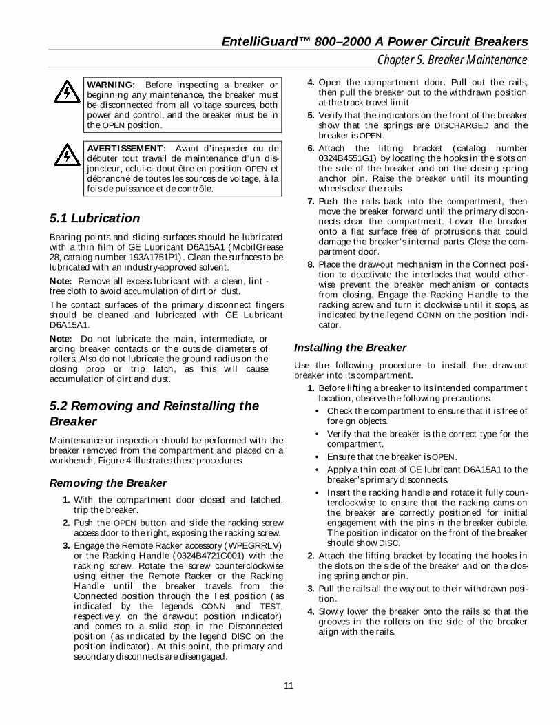
5.2 Removing and Reinstalling the Breaker Maintenance or inspection should be performed with the breaker removed from the compartment and placed on a workbench. Figure 4 illustrates these procedures.
Removing the Breaker 1. With the compartment door closed and latched,
trip the breaker. 2. Push the OPEN button and slide the racking screw
access door to the right, exposing the racking screw. 3. Engage the Remote Racker accessory (WPEGRRLV)
or the Racking Handle (0324B4721G001) with the racking screw. Rotate the screw counterclockwise using either the Remote Racker or the Racking Handle until the breaker travels from the Connected position through the Test position (as indicated by the legends CONN and TEST, respectively, on the draw-out position indicator) and comes to a solid stop in the Disconnected position (as indicated by the legend DISC on the position indicator). At this point, the primary and secondary disconnects are disengaged.
4. Open the compartment door. Pull out the rails, then pull the breaker out to the withdrawn position at the track travel limit
5. Verify that the indicators on the front of the breaker show that the springs are DISCHARGED and the breaker is OPEN.
6. Attach the lifting bracket (catalog number 0324B4551G1) by locating the hooks in the slots on the side of the breaker and on the closing spring anchor pin. Raise the breaker until its mounting wheels clear the rails.
7. Push the rails back into the compartment, then move the breaker forward until the primary discon-nects clear the compartment. Lower the breaker onto a flat surface free of protrusions that could damage the breaker’s internal parts. Close the com-partment door.
8. Place the draw-out mechanism in the Connect posi-tion to deactivate the interlocks that would other-wise prevent the breaker mechanism or contacts from closing. Engage the Racking Handle to the racking screw and turn it clockwise until it stops, as indicated by the legend CONN on the position indi-cator.
Installing the Breaker Use the following procedure to install the draw-out breaker into its compartment.
1. Before lifting a breaker to its intended compartment location, observe the following precautions:
• Check the compartment to ensure that it is free of foreign objects.
• Verify that the breaker is the correct type for the compartment.
• Ensure that the breaker is OPEN. • Apply a thin coat of GE lubricant D6A15A1 to the
breaker’s primary disconnects. • Insert the racking handle and rotate it fully coun-
terclockwise to ensure that the racking cams on the breaker are correctly positioned for initial engagement with the pins in the breaker cubicle. The position indicator on the front of the breaker should show DISC.
2. Attach the lifting bracket by locating the hooks in the slots on the side of the breaker and on the clos-ing spring anchor pin.
3. Pull the rails all the way out to their withdrawn posi-tion.
4. Slowly lower the breaker onto the rails so that the grooves in the rollers on the side of the breaker align with the rails.

EntelliGuard™ 800–2000 A Power Circuit Breakers Chapter 5. Breaker Maintenance
12
Figure 4. Installing the breaker into the compartment.
EntelliGuard™ 800–2000 A Power Circuit Breakers Chapter 5. Breaker Maintenance
13
5. Push the breaker into the compartment until it reaches the stops. This is the Disconnect position (as shown by the legend DISC on the draw-out posi-tion indicator). At this point the racking arms are positioned to engage the fixed racking pins in the compartment and are ready to begin the racking motion. Push the rails back into the compartment.
6. Close the compartment door. Push the OPEN button and slide the racking screw access door to the right, exposing the racking screw.
7. Engage the Remote Racker accessory or the Racking Handle with the racking screw. Rotate the screw clockwise using either the Remote Racker or the Racking Handle through the Test position, until the racking screw comes to a solid stop. The breaker is now in the Connected position, as shown by the legend CONN on the position indicator flag. Note that a loud click will be heard as the spring-loaded secondary disconnect detent releases as the breaker moves beyond the TEST position.
8. Depress the red OPEN button to close the racking screw access door to permit breaker closing.
5.3 Slow Closing the Breaker Closing the breaker slowly, while observing the action of the mechanism and contacts, is a good way to judge the correctness of mechanical and contact relationships. Some of the maintenance procedures described later involve slow closing the breaker. Use the following proce-dure to slow close the breaker:
1. Remove the escutcheon. (See Section 7.5) 2. The closing spring must be isolated from the
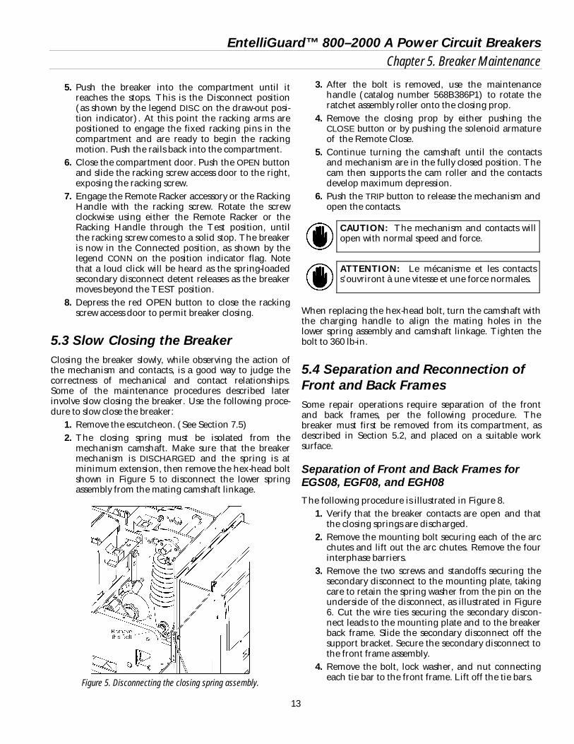
mechanism camshaft. Make sure that the breaker mechanism is DISCHARGED and the spring is at minimum extension, then remove the hex-head bolt shown in Figure 5 to disconnect the lower spring assembly from the mating camshaft linkage.
Figure 5. Disconnecting the closing spring assembly.
3. After the bolt is removed, use the maintenance handle (catalog number 568B386P1) to rotate the ratchet assembly roller onto the closing prop.
4. Remove the closing prop by either pushing the CLOSE button or by pushing the solenoid armature of the Remote Close.
5. Continue turning the camshaft until the contacts and mechanism are in the fully closed position. The cam then supports the cam roller and the contacts develop maximum depression.
6. Push the TRIP button to release the mechanism and open the contacts.
CAUTION: The mechanism and contacts will open with normal speed and force.
ATTENTION: Le mécanisme et les contacts s’ouvriront à une vitesse et une force normales.
When replacing the hex-head bolt, turn the camshaft with the charging handle to align the mating holes in the lower spring assembly and camshaft linkage. Tighten the bolt to 360 lb-in.
5.4 Separation and Reconnection of Front and Back Frames Some repair operations require separation of the front and back frames, per the following procedure. The breaker must first be removed from its compartment, as described in Section 5.2, and placed on a suitable work surface.
Separation of Front and Back Frames for EGS08, EGF08, and EGH08 The following procedure is illustrated in Figure 8.
1. Verify that the breaker contacts are open and that the closing springs are discharged.
2. Remove the mounting bolt securing each of the arc chutes and lift out the arc chutes. Remove the four interphase barriers.
3. Remove the two screws and standoffs securing the secondary disconnect to the mounting plate, taking care to retain the spring washer from the pin on the underside of the disconnect, as illustrated in Figure 6. Cut the wire ties securing the secondary discon-nect leads to the mounting plate and to the breaker back frame. Slide the secondary disconnect off the support bracket. Secure the secondary disconnect to the front frame assembly.
4. Remove the bolt, lock washer, and nut connecting each tie bar to the front frame. Lift off the tie bars.

EntelliGuard™ 800–2000 A Power Circuit Breakers Chapter 5. Breaker Maintenance
14
5. Remove the four bolts, washers, and nuts that attach the secondary disconnect mounting plate to the back frame. Remove the mounting plate.
6. Remove one of the snap rings and slide out the pin connecting each of the movable contact assemblies to the breaker main shaft, as illustrated in Figure 7.
7. Carefully place the breaker on its back, resting on the primary disconnects.
8. Remove the six bolts and lock washers attaching the front and back frames on the side panels.
9. Lift the front frame straight off the back frame.
Reconnection of Front and Back Frames for EGS08, EGF08, and EGH08 The following procedure is illustrated in Figure 8.
1. Carefully place the back frame on a suitable work surface, resting on the primary disconnects.
2. Place the front frame assembly onto the back frame, being careful to line up the mounting holes in the side panels. Insert the six bolts and lock washers and tighten them to 200 in-lb.
3. Carefully place the breaker upright, resting on its bottom surface.
4. Reconnect the movable contact assemblies to the breaker main shaft by inserting the connecting pin and reattaching the snap ring, as illustrated in Figure 7.
5. Place the secondary disconnect mounting plate in position and secure with the four bolts, washers, and nuts.
6. Connect the ends of the tie bars to the secondary disconnect mounting plate and attach the other ends to the front frame with the bolt, lock washer, and nut removed earlier. Tighten to 96 in-lb.
7. Place the flexible washer on the molded pin on the bottom of the secondary disconnect, then slide the two feet into the slots on the mounting plate. Secure with the two screws and standoffs, as illustrated in Figure 6. Replace the wire bundle into the channel on the top of the frame and secure with wire ties.
8. Insert the four interphase barriers into their mount-ing slots.
9. Slide the arc chutes into position, with the slots over the movable contact arms. Secure with the bolts and lock washers removed on disassembly.
10. Check that no wires are interfering with breaker operation and that all bolts and nuts are tight. Operate the breaker a few times to verify proper operation.
Figure 6. Removing or installing the secondary disconnect.
Figure 7. Movable contact connection to the breaker main shaft on
EGS08, EGF08, and EGH08 breakers.

EntelliGuard™ 800–2000 A Power Circuit Breakers Chapter 5. Breaker Maintenance
15
Figure 8. Separating the front and back frames on EGS08, EGF08, and EGH08 breakers.

EntelliGuard™ 800–2000 A Power Circuit Breakers Chapter 5. Breaker Maintenance
16
Separation of Front and Back Frames for EGX08, EGS16, EGF16, EGH16, EGS20, and EGF20 The following procedure is illustrated in Figure 10.
1. Verify that the breaker contacts are open and that the closing springs are discharged.
2. Remove the two bolts and lock washers that attach the arc chute retainer to the front frame and remove the retainer. Slide out the arc chutes and interphase barriers. Note that there are three dis-tinct types of phase barriers: right, inner (2), and left.
3. Remove the two screws and standoffs securing each secondary disconnect to the mounting plate, taking care to retain the spring washer from the pin on the underside of the disconnect, as illustrated in Figure 6. Cut the wire ties securing the secondary discon-nect leads to the mounting plate and to the breaker back frame. Slide the secondary disconnect off the support bracket. Secure the secondary disconnect to the front frame assembly.
4. Remove the three screws and washers that attach the secondary disconnect mounting plate to the back frame. Remove the mounting plate.
5. Remove one of the snap rings and slide out the pin connecting each of the movable contact assemblies to the breaker main shaft, as illustrated in Figure 9. On the two outer poles, first remove the bolt and cover over the outer end of the pin.
6. Carefully place the breaker on its back, resting on the primary disconnects.
7. Remove the two nuts and lock washers attaching the tie bars to the front frame.
8. Remove the six nuts and lock washers (the top con-nections also have spacers) connecting the front and back frames.
9. Lift the front frame straight off the back frame.
Reconnection of Front and Back Frames for EGX08, EGS16, EGF16, EGH16, EGS20, and EGF20 The following procedure is illustrated in Figure 10.
1. Carefully place the back frame on a suitable work surface, resting on the primary disconnects.
2. Carefully lower the front frame onto the back frame, lining up the six studs in the sides of the back frame with the corresponding holes in the front frame. Attach the six nuts and lock washers, with the two spacers on the top studs, and tighten to 250 in-lb.
Figure 9. Movable contact connection to the breaker main shaft on
EGX08, EGS16, EGF16, EGH16, EGS20, and EGF20 breakers.
3. Attach the two nuts and lock washers to secure the tie bars to the front frame. Tighten to 250 in-lb.
4. Carefully place the breaker upright, resting on its bottom surface.
5. Reconnect the movable contact assemblies to the breaker main shaft by inserting the connecting pin and reattaching the snap ring, as illustrated in Figure 9. Reattach the cover and bolt on the two outer poles.
6. Reattach the secondary disconnect mounting plate with three screws and washers to the back frame.
7. Place the flexible washer on the molded pin on the bottom of the secondary disconnect, then slide the two feet into the slots on the mounting plate. Secure with the two screws and standoffs, as illustrated in Figure 6. Replace the wire bundle into the channel on the top of the frame and secure with wire ties.
8. Insert the four interphase barriers into position, noting the proper locations for the three different types.
9. Slide the arc chutes into position. Place the arc chute retainer in position and secure with the two bolts and lock washers to the front frame. Tighten securely.
10. Check that no wires are interfering with breaker operation and that all bolts and nuts are tight. Operate the breaker a few times to verify proper operation.

EntelliGuard™ 800–2000 A Power Circuit Breakers Chapter 5. Breaker Maintenance
17
left
Figure 10. Separating the front and back frames on EGX08, EGPS16, EGF16, EGH16, EGS20, and EGF20 breakers (EGS20 illustrated).

EntelliGuard™ 800–2000 A Power Circuit Breakers Chapter 5. Breaker Maintenance
18
5.5 Breaker Mechanism Operation and Adjustment Figure 11, Figure 12, and Figure 13 show the mechanism components in the CLOSED, TRIPPED, and RESET conditions, respectively. Numbers in parentheses refer to the indicated items in the figures listed in Table 5. The closing spring is in the charged position for all of these details. Closed Position – The movable contacts are pushed against the stationary contacts by the toggle linkage, as illustrated in Figure 11. The toggle linkage is held in position through the engagement of its cam roller (4), with the prop (1), the secondary latch/roller (5), the secondary latch (10), and the trip latch (7). Tripped Position – The mechanism goes from the CLOSED position to the TRIPPED position, illustrated in Figure 12, when the trip shaft (6) is rotated by either the manual trip button or one of the other trip devices. The trip latch (7) is assembled to the trip shaft. When the trip shaft rotates, the trip latch disengages from the secondary latch roller (5). The secondary latch pivots, resulting in the collapse of the toggle linkage. This collapse, along with the open-ing spring (11), shown in Figure 13, causes the breaker contacts to open. Reset Position – The closing cam (2), assembled to the cam shaft (3), is rotated by the Charging Motor, manual charging handle, or maintenance handle. The cam engages the cam roller and partially extends the toggle linkage. This allows the secondary latch (10) to pivot against the front frame, as illustrated in Figure 13, leaving a gap between the trip latch (7) and secondary latch roller (5). The secondary latch is now in a position to engage both the trip latch and cam roller (4). The breaker closes when the closing springs discharge and rotate the cam (2) against the cam roller (4). The toggle linkage is fully extended, pivoting the secondary latch (10) from the front frame and engaging it with the trip latch (7) and cam roller (4), as shown in Figure 11. When the breaker is closed and the closing spring is dis-charged, the upper cam roller (4) is supported by the cam (2) rather than the prop (1). The mechanism must be in this position to check contact adjustment, as described in Chapter 6.
Figure 11. Breaker mechanism in the CLOSED position.
Figure 12. Breaker mechanism in the TRIPPED position.
Figure 13. Breaker mechanism in the RESET position.
1 Prop 7 Trip latch 2 Cam 8 Insulated coupling 3 Camshaft 9 Main shaft 4 Cam roller 10 Secondary latch 5 Secondary latch
roller 11 Opening spring
6 Trip shaft
Table 5. Key to numbered parts in Figure 11, Figure 12, and Figure 13.

EntelliGuard™ 800–2000 A Power Circuit Breakers Chapter 5. Breaker Maintenance
19
Trip Latch Adjustment Use the following procedure to adjust the trip latch, as illustrated in Figure 14.
1. Remove the breaker from its compartment and place it on a suitable work surface.
2. Remove the arc chutes and phase barriers, as described in Section 6.2.
3. Charge the closing springs with the manual charg-ing handle and close the breaker.
4. Turn the trip latch adjustment screw in (clockwise) until the breaker trips. Withdraw the screw (counter-clockwise) 41/2 turns.
Figure 14. Adjusting the trip latch.

EntelliGuard™ 800–2000 A Power Circuit Breakers Chapter 6. Contact Maintenance
20
6.1 Introduction Breakers subjected to frequent interruption of high cur-rents may eventually require replacement of their con-tacts. The general rule for determining if replacement is required is the loss of one-half or more of the mass of the contact tip material. Roughening or light pitting of the contact surface does not indicate loss of ability to carry or interrupt current. When contacts are replaced, they must be adjusted to ensure that the proper force and contact depression is developed between the movable and stationary contacts when the breaker is closed. This is called the wipe adjust-ment. Wipe is the distance through which the stationary contacts move when the breaker closes. It is measured between the point of contact on a stationary contact when the breaker is open and the position of the same point when the breaker is closed. The actual wiping motion is greater than this measurement, since the contacts over-travel. The wipe adjustment provides proper depression to assure full current-carrying capacity without overheating and influences proper current transfer during interruption of fault currents. Transfer of the current is the forced sequential movement from the main to the intermediate contacts, then to the arcing contacts, to the arc runner, and finally to the arc chutes, where energy is dissipated and the arc is extinguished. Contact wipe should be checked periodically during normal maintenance inspec-tions and after any overcurrent trip.
CAUTION: Before performing any contact adjustment or replacement, disable the closing springs, as described in Section 5.3.
ATTENTION: Avant d’effectuer tout ajustement ou remplacement de contact, neutraliser les ressorts de fermeture, tel que décrit à la Section 5.3.
6.2 Arc Chute Removal and Replacement The arc chutes should be removed and inspected at the regular inspection period. Arc chutes and interphase bar-riers are available as renewal parts. The breaker must be removed from its compartment, as described in Section 5.2, and placed on a suitable work surface. There are two types of arc chutes used in these breakers, depending on frame size.
Arc Chutes in EGS08, EGF08, and EGH08 Breakers Use the following procedure to remove and replace the arc chutes, as illustrated in Figure 8.
1. Verify that the breaker contacts are open and the closing springs are discharged.
2. Remove the mounting bolt and lock washer secur-ing each of the arc chutes and lift out the arc chutes. Remove the four interphase barriers.
3. Check the arc chutes and barriers for damage and replace them, if necessary.
4. Replace the four interphase barriers into their slots. 5. Slide the arc chutes into place, with the slots over
the movable contact arms. 6. Replace the mounting bolt and lock washer secur-
ing each arc chute to the breaker frame.
CAUTION: All insulating barriers must be in place before the breaker is placed back into service.
ATTENTION: Toutes les barriéres isolatrices doivent être en place avant que le disjoncteur ne soit replacé en service.
Arc Chutes in EGX08, EGS16, EGF16, EGH16, EGS20, and EGF20 Breakers Use the following procedure to remove and replace the arc chutes, as illustrated in Figure 10.
1. Verify that the breaker contacts are open and the closing springs are discharged.
2. Remove the two bolts and lock washers that attach the arc chute retainer to the front frame and remove the retainer.
3. Slide out the arc chutes and interphase barriers. Note that there are three distinct types of phase bar-riers: right, inner (2), and left.
4. Check the arc chutes and barriers for damage and replace them, if necessary.
5. Replace the four interphase barriers into their cor-rect slots.
6. Slide the arc chutes into place, with the slots over the movable contact arms.
7. Replace the arc chute retainer bar and secure it with two bolts and lock washers.
CAUTION: All insulating barriers must be in place before the breaker is placed back into service.
EntelliGuard™ 800–2000 A Power Circuit Breakers Chapter 6. Contact Maintenance
21
ATTENTION: Toutes les barriéres isolatrices doivent être en place avant que le disjoncteur ne soit replacé en service.
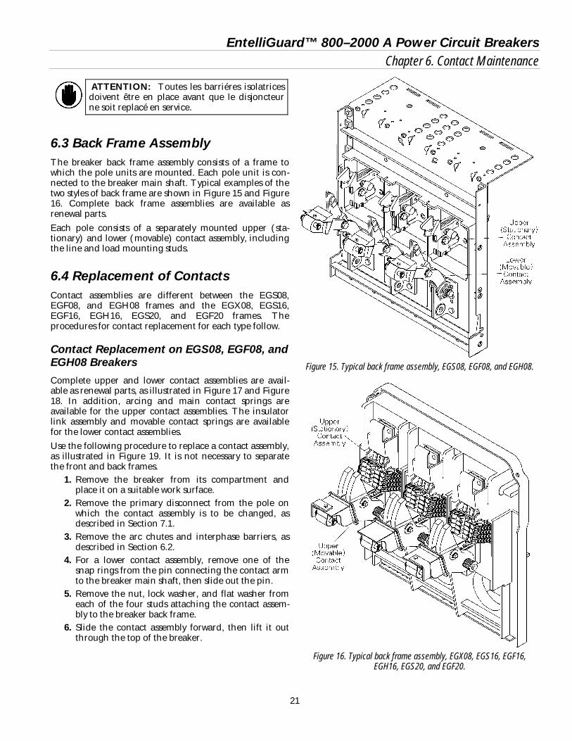
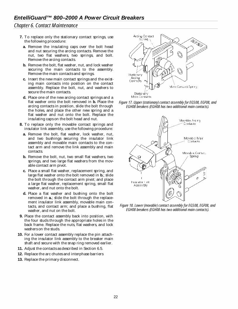
6.3 Back Frame Assembly The breaker back frame assembly consists of a frame to which the pole units are mounted. Each pole unit is con-nected to the breaker main shaft. Typical examples of the two styles of back frame are shown in Figure 15 and Figure 16. Complete back frame assemblies are available as renewal parts. Each pole consists of a separately mounted upper (sta-tionary) and lower (movable) contact assembly, including the line and load mounting studs.
6.4 Replacement of Contacts Contact assemblies are different between the EGS08, EGF08, and EGH08 frames and the EGX08, EGS16, EGF16, EGH16, EGS20, and EGF20 frames. The procedures for contact replacement for each type follow.
Contact Replacement on EGS08, EGF08, and EGH08 Breakers Complete upper and lower contact assemblies are avail-able as renewal parts, as illustrated in Figure 17 and Figure 18. In addition, arcing and main contact springs are available for the upper contact assemblies. The insulator link assembly and movable contact springs are available for the lower contact assemblies. Use the following procedure to replace a contact assembly, as illustrated in Figure 19. It is not necessary to separate the front and back frames.
1. Remove the breaker from its compartment and place it on a suitable work surface.
2. Remove the primary disconnect from the pole on which the contact assembly is to be changed, as described in Section 7.1.
3. Remove the arc chutes and interphase barriers, as described in Section 6.2.
4. For a lower contact assembly, remove one of the snap rings from the pin connecting the contact arm to the breaker main shaft, then slide out the pin.
5. Remove the nut, lock washer, and flat washer from each of the four studs attaching the contact assem-bly to the breaker back frame.
6. Slide the contact assembly forward, then lift it out through the top of the breaker.
Figure 15. Typical back frame assembly, EGS08, EGF08, and EGH08.
Figure 16. Typical back frame assembly, EGX08, EGS16, EGF16,
EGH16, EGS20, and EGF20.
EntelliGuard™ 800–2000 A Power Circuit Breakers Chapter 6. Contact Maintenance
22
7. To replace only the stationary contact springs, use the following procedure:
a. Remove the insulating caps over the bolt head and nut securing the arcing contacts. Remove the nut, two flat washers, two springs, and bolt. Remove the arcing contacts.
b. Remove the bolt, flat washer, nut, and lock washer securing the main contacts to the assembly. Remove the main contacts and springs.
c. Insert the new main contact springs and the exist-ing main contacts into position on the contact assembly. Replace the bolt, nut, and washers to secure the main contacts.
d. Place one of the new arcing contact springs and a flat washer onto the bolt removed in b. Place the arcing contacts in position, slide the bolt through the holes, and place the other new spring and a flat washer and nut onto the bolt. Replace the insulating caps on the bolt head and nut.
8. To replace only the movable contact springs and insulator link assembly, use the following procedure:
a. Remove the bolt, flat washer, lock washer, nut, and two bushings securing the insulator link assembly and movable main contacts to the con-tact arm and remove the link assembly and main contacts.
b. Remove the bolt, nut, two small flat washers, two springs, and two large flat washers from the mov-able contact arm pivot.
c. Place a small flat washer, replacement spring, and large flat washer onto the bolt removed in b.; slide the bolt through the contact arm pivot; and place a large flat washer, replacement spring, small flat washer, and nut onto the bolt.
d. Place a flat washer and bushing onto the bolt removed in a.; slide the bolt through the replace-ment insulator link assembly, movable main con-tacts, and contact arm; and place a bushing, flat washer, and nut on the bolt.
9. Place the contact assembly back into position, with the four studs through the appropriate holes in the back frame. Replace the nuts, flat washers, and lock washers on the studs.
10. For a lower contact assembly replace the pin attach-ing the insulator link assembly to the breaker main shaft and secure with the snap ring removed earlier.
11. Adjust the contacts as described in Section 6.5. 12. Replace the arc chutes and interphase barriers 13. Replace the primary disconnect.
Figure 17. Upper (stationary) contact assembly for EGS08, EGF08, and
EGH08 breakers (EGH08 has two additional main contacts).
Figure 18. Lower (movable) contact assembly for EGS08, EGF08, and
EGH08 breakers (EGH08 has two additional main contacts).

EntelliGuard™ 800–2000 A Power Circuit Breakers Chapter 6. Contact Maintenance
23
Figure 19. Removal and installation of contact assemblies on EGS08, EGF08, and EGH08 breakers.
EntelliGuard™ 800–2000 A Power Circuit Breakers Chapter 6. Contact Maintenance
24
Contact Replacement on EGX08, EGS16, EGF16, EGH16, EGS20, and EGF20 Breakers For the following procedures, illustrated in Figure 20, the breaker must be removed from its compartment and placed on a suitable working surface. Remove the arc chutes and interphase barriers, as described in Section 6.2.
Stationary Contacts
Use the following procedure to replace the stationary con-tacts.
1. Remove the four screws holding the arc runner in place and remove the arc runner. Take care not to damage or lose the insulating washer underneath the lock washer and flat washer on the two lower screws.
2. For replacement of stationary main and intermedi-ate contacts:
a. Release each contact spring by holding the corre-sponding intermediate or main contact, extend-ing the spring, and removing the spring from the contact. The end pieces of each spring have a small hole for inserting a spring puller.
b. Remove each contact as its spring is disengaged. Clean off the existing lubricant on the pivot area. Replace with a small amount of GE Lubricant D6A15A1 (MobilGrease 28, catalog number 193A1751P1).
c. Insert each replacement main and intermediate contact and secure with its contact spring. Note that main and intermediate contacts are differentiated by the number of chamfers on the corners of the contact surfaces, as illustrated in Figure 21. It is important that this distinction be observed when replacing the contacts.
3. For replacement of stationary arcing contacts, as illustrated in Figure 22:
a. Remove the two screws and lock washers securing the arcing contact pivot to the assembly and remove the pivot.
b. Remove the insulating spacers, contact pin, and arcing contacts.
c. Insert the replacement arcing contacts, the con-tact pin, and insulating spacers.
d. Place the arcing contact pivot in position and secure with its two screws and lock washers.
4. Place the arc runner in position and secure with its four screws. Ensure that the insulating washers are in place on the lower screws. Tighten the screws to 45 in-lb.
Movable Contacts
Use the following procedure to replace the movable con-tacts.
1. Remove the snap ring from the coupling pin and slide out the pin.
2. Remove the screw, washer, and spring from one side of the pivot pin. Carefully remove the pivot pin.
3. Slip out the contact arms. 4. Clean any existing lubricant from the pivot pin.
Place a small amount of GE Lubricant D6A15A1 (MobilGrease 28, catalog number 193A1751P1) on the pivot pin and the pivot surfaces of the new contact arms.
5. Install the new arm, insert the pivot pin, and replace the pivot spring, washer, and screw. Tighten to 90 in-lb.
6. Install the coupling pin and secure with the snap ring.
7. Adjust the contacts as described in Section 6.5.

EntelliGuard™ 800–2000 A Power Circuit Breakers Chapter 6. Contact Maintenance
25
Figure 20. Removal and installation of contact assemblies on EGX08, EGS16, EGF16, EGH16, EGS20, and EGF20 breakers.
Figure 21. Stationary main and intermediate contact styles.
Figure 22. Replacement of stationary arcing contacts.

EntelliGuard™ 800–2000 A Power Circuit Breakers Chapter 6. Contact Maintenance
26
6.5 Adjusting the Contacts Adjust the contact depression whenever contacts are replaced. In addition, check and adjust, as necessary, at the normal maintenance interval.
Contact Adjustment on EGS08, EGF08, and EGH08 Breakers The following procedure is illustrated in Figure 23.
1. Contact depression is correct if the center of the roll pin falls within the two sides of the scribed adjust-ment mark on the side of the stationary main con-tact.
2. If adjustment is necessary, remove the nut, washer, and bushing from the end of the pivot bolt securing the insulator link assembly to the movable contact arm, then remove the bolt and other washer and bushing.
3. Turn the contact adjusting link in or out of the insu-lator link assembly. Increase its length to increase contact depression and shorten the link to decrease contact depression.
4. Reassemble the insulator link assembly to the con-tact arm with the pivot bolt, nut, two washers, and two bushings.
Contact Adjustment on EGX08, EGS16, EGF16, EGH16, EGS20, and EGF20 Breakers The following procedure is illustrated in Figure 24.
1. Remove the arc chutes and phase barriers, as described in Section 6.2.
2. To establish a reference for measurement, fasten the aluminum arc chute retainer to the breaker mechanism frame with small C clamps, as shown. Ensure that the C clamps do not interfere with any moving parts.
3. Measure dimension ‘A’ with the contacts open and again with the contacts closed. Note that the meas-urement is made from the second contact spring end (first stationary main contact). The difference in the measurements should be 0.06–0.10 inch, which provides 0.05–0.08 inch main contact depres-sion.
4. To adjust contact depression, do the following: a. Remove the retaining ring from one side of the
pin connecting the drive link to the movable con-tact arms and remove the pin.
b. Adjust the depression by turning the link in one-half-turn increments. Note that the link has left-hand threads. One-half turn changes dimension A by about 0.03 inch, which is equivalent to about 0.02 inch in contact depression.
5. Repeat for all poles.
Figure 23. Contact adjustment on EGS08, EGF08, and EGH08 breakers.

EntelliGuard™ 800–2000 A Power Circuit Breakers Chapter 6. Contact Maintenance
27
Figure 24. Contact adjustment on EGX08, EGS16, EGF16, EGH16, EGS20, and EGF20 breakers.

EntelliGuard™ 800–2000 A Power Circuit Breakers Chapter 7. Maintenance of Standard Parts and Assemblies
28
This section describes procedures for replacing the stan-dard parts and assemblies available as renewal parts. Before any of the operations in this chapter can be per-formed, the breaker must be removed from its compart-ment, as described in Section 5.2, and placed on a suitable work surface.
7.1 Primary Disconnects Primary disconnects provide the flexible connection between the breaker line and load terminals and the equipment line and load terminals. Primary disconnect assemblies are different between the EGS08, EGF08, and EGH08 frames, as illustrated in Figure 25, and the EGX08, EGS16, EGF16, EGH16, EGS20, and EGF20 frames, as illustrated in Figure 26. The procedures for removal and installation of the two types are described below.
Primary Disconnect Replacement on EGS08, EGF08, and EGH08 Breakers The following procedure is illustrated in Figure 27. To remove a primary disconnect assembly, squeeze the disconnect fingers together with a suitable tool until the assembly releases from the stud, then slide it off. To install a primary disconnect assembly, squeeze the dis-connect fingers together with a suitable tool, slide the assembly over the stud, then reduce the pressure on the fingers until they close into the slots on the stud.
Primary Disconnect Removal on EGX08, EGS16, EGF16, EGH16, EGS20, and EGF20 Breakers The following procedure is illustrated in Figure 28.
1. Remove the two nuts from one of the long bolts holding the primary disconnect assembly together.
2. Carefully slide out the bolt while removing the flat washer, spring, bushing, upper retainer, bow-tie spacers, and disconnect fingers from the top and the bow-tie spacers, lower retainer, and fingers from the bottom of the assembly.
3. Repeat for the other assembly bolt and components. 4. Slide off the spring clips and remove the two stud
spacers. 5. Remove the main retainer from the stud.
Figure 25. Primary disconnect assembly for EGS08, EGF08, and EGH08
breakers.
Figure 26. Primary disconnect assembly for EGX08, EGS16, EGF16,
EGH16, EGS20, and EGF20 breakers.

EntelliGuard™ 800–2000 A Power Circuit Breakers Chapter 7. Maintenance of Standard Parts and Assemblies
29
Figure 27. Primary disconnect removal and installation on EGS08, EGF08, and EGH08 breakers.
Primary Disconnect Installation on EGX08, EGS16, EGF16, EGH16, EGS20, and EGF20 Breakers
1. Slide the main retainer over the stud. 2. Position each of the stud spacers, in turn, in the
holes in the stud and secure with the spring clips. Note that the holes in the stud spacers are off center and must be positioned with the hole toward the back of the breaker to align with the holes in the clips.
3. Set a pair of bow-tie spacers into one of the fingers, place a retainer over the spacers to hold them in position, then turn the subassembly over. Slide a long bolt through the hole in the retainer and fin-ger, then through the clip and stud spacer. Hold the bottom finger subassembly in place.
4. Place a finger through the bolt from the top, then place two bow-tie spacers in the finger and hold them in position with a retainer.
5. Place a spring, bushing, and flat washer over the bolt, then secure with the two nuts.
6. Repeat steps 3–5 for the other half of the pole. 7. The primary disconnect assembly on new breakers is
adjusted in the factory for a force of 85–105 pounds on a 1/2-inch-thick copper bar between the fingers. This force range can be obtained after installation of a new primary disconnect assembly by adjusting the finger spacing as shown in Figure 29. Loosen the lock nuts to obtain a spacing of 0.766–0.797 inch between the top of the upper retainer and the bottom of the flat washer. Tighten the lock nuts.

EntelliGuard™ 800–2000 A Power Circuit Breakers Chapter 7. Maintenance of Standard Parts and Assemblies
30
Figure 28. Primary disconnect removal and installation on EGX08, EGS16, EGF16, EGH16, EGS20, and EGF20 breakers.
Figure 29. Primary disconnect adjustment on EGX08, EGS16, EGF16,
EGH16, EGS20, and EGF20 breakers.

EntelliGuard™ 800–2000 A Power Circuit Breakers Chapter 7. Maintenance of Standard Parts and Assemblies
31
7.2 Secondary Disconnect The secondary disconnect, illustrated in Figure 30, pro-vides connections between the breaker control circuits and external circuit elements. It is attached to a mounting plate on the breaker back frame. It automatically makes or breaks the control circuit connections as the breaker is racked in or out of its compartment. Figure 31 illustrates the numbering of the terminals in the secondary disconnect.
Secondary Disconnect Removal To remove a secondary disconnect, use the following pro-cedure, as illustrated in Figure 32.
1. Unplug all control circuit wires from the secondary disconnect, carefully marking each wire with its position number in the disconnect.
2. Remove the two screws and standoffs securing the disconnect to the mounting plate.
3. Slide the disconnect mounting feet out of the slots in the mounting plate. Remove the spring washer if it has detached from the molded pin on the under-side of the disconnect.
Secondary Disconnect Installation To replace a secondary disconnect, use the following procedure, as illustrated in Figure 32.
1. Place the spring washer on the molded pin on the underside of the disconnect body and hold it in place.
2. Slide the mounting feet on the disconnect into the two slots in the secondary disconnect mounting plate.
3. Place the two screws and standoffs into the slots on the front of the disconnect and into the tapped holes in the mounting plate. Tighten to 40 in-lb.
4. Insert the control circuit wires into the correct posi-tions in the secondary disconnect.
Figure 30. Secondary disconnect.
Figure 31. Secondary disconnect terminal numbering. (As seen from
the front of the breaker.)
Figure 32. Removing or installing the secondary disconnect.

EntelliGuard™ 800–2000 A Power Circuit Breakers Chapter 7. Maintenance of Standard Parts and Assemblies
32
7.3 Flux Shifter The function of the flux shifter, illustrated in Figure 33, is to actuate the trip shaft and trip the breaker upon receiv-ing a signal from the EntelliGuard Messenger™.
Flux Shifter Adjustment The only adjustment required to the flux shifter mecha-nism is the trip rod length. As shown in Figure 34, the clearance between the trip rod end and the trip paddle is set to 0.11 ± 0.03 inch. To make this adjustment, open the breaker and charge the closing springs to restore the mechanism to the Reset position. Loosen the lock nut on the trip rod, rotate the adjuster until the proper gap is attained, then retighten the lock nut.
Removing the Flux Shifter The following procedure is illustrated in Figure 35.
1. Remove the snap ring connecting the reset arm to the main shaft and slide the arm off its mounting point.
2. Unplug the connector at the end of the flux shifter leads.
3. Remove the two mounting bolts and lock washers from underneath the breaker base, then lift off the flux shifter.
Installing the Flux Shifter The following procedure is illustrated in Figure 35.
1. Put the replacement flux shifter into position, lining up the solenoid plunger with the end of the trip rod and the operations counter link (if present) with the end of the reset arm. Insert the two bolts and lock washers from beneath the bottom plate of the breaker and tighten to 32 in-lb.
2. Slide the end of the reset arm onto the connection on the breaker main shaft and secure with the snap ring.
3. Connect the leads to the secondary disconnect.
Figure 33. Flux shifter.
Figure 34. Flux shifter adjustment.

EntelliGuard™ 800–2000 A Power Circuit Breakers Chapter 7. Maintenance of Standard Parts and Assemblies
33
Figure 35. Removal or installation of a flux shifter.

EntelliGuard™ 800–2000 A Power Circuit Breakers Chapter 7. Maintenance of Standard Parts and Assemblies
34
7.4 Draw-Out Mechanism EntelliGuard circuit breakers are installed in GE Entellisys™ Low-Voltage Switchgear. Draw-out construction permits activation of a new feeder, allows rapid replacement of a circuit breaker, and facilitates inspection and maintenance of the breaker with no need to deenergize the entire switchgear lineup. The draw-out racking mechanism, illustrated in Figure 36, is available as a replacement assembly.
Figure 36. Draw-out racking mechanism.
Draw-Out Mechanism Removal The following procedure describes the removal of the draw-out mechanism, as illustrated in Figure 38.
1. Position the breaker on a suitable work surface so that its underside is accessible.
2. Remove the snap ring connecting the interlock link to the breaker mechanism.
3. Remove the two bolts, lock washers, and nuts con-necting each side mounting bracket to the sides of the breaker.
4. Remove the four bolts and lock washers connecting the bottom mounting brackets to the tapped holes in the bottom plate of the breaker and lift off the mechanism.
Draw-Out Mechanism Installation The following procedure describes the installation of the draw-out mechanism, as illustrated in Figure 38.
1. Put the replacement mechanism in position on the bottom of the breaker, then insert the four bolts and lock washers through the bottom mounting brackets into the tapped holes in the bottom plate of the breaker. Tighten to 96 in-lb.
2. Attach the two side mounting brackets to the sides of the breaker with two bolts, lock washers, and nuts each. Tighten to 96 in-lb.
3. Position the interlock link on the mounting pin of the breaker mechanism and secure with the snap ring.
Draw-Out Mechanism Adjustment After installation of a replacement draw-out mechanism, adjust the draw-out mechanism
1. With the trunnion against the jamb nut washers, check that the distance between the edge of the washers and the collar is 6.16 inch, as illustrated in Figure 37. To adjust this dimension, loosen and rotate the jamb nuts appropriately, then retighten the nuts.
2. The length of the sleeve is adjusted to stop the trunnion when the distance between the ends of the equipment and breaker studs in 0.03 to 0.22 inch. To adjust this dimension, loosen the set screw in the collar, turn the sleeve to increase or decrease its length appropriately, then retighten the set screw.
Figure 37. Draw-out mechanism adjustment.

EntelliGuard™ 800–2000 A Power Circuit Breakers Chapter 7. Maintenance of Standard Parts and Assemblies
35
Figure 38. Draw-out racking mechanism removal and installation.

EntelliGuard™ 800–2000 A Power Circuit Breakers Chapter 7. Maintenance of Standard Parts and Assemblies
36
7.5 Escutcheon The escutcheon is illustrated in Figure 39.
Figure 39. Escutcheon and related parts.
Escutcheon Removal Use the following procedure to remove the escutcheon:
1. Pull the ends of the two trim plate mounting rods out of the holes at the rear of both sides of the escutcheon, then remove the trim plate.
2. Remove the six screws securing the escutcheon to the breaker. Pull the manual charging handle out part way, then slide off the escutcheon.
Escutcheon Installation Use the following procedure to install the escutcheon:
1. Pull the manual charging handle out part way, then slide the handle through the slot in the replacement escutcheon and move the escutcheon into place. Insert the six mounting screws and tighten to 14–20 in-lb.
2. Replace the trim ring around the escutcheon, with the narrow side at the bottom. Insert the trim plate mounting rods into the rear of the escutcheon.
7.6 Charging Handle The charging handle, illustrated in Figure 40, is available as a renewal part. See DEF004.
Removing the Charging Handle Use the following procedure to remove the charging han-dle, as illustrated in Figure 41 and Figure 42.
1. Remove the escutcheon, as described in Section 7.5. 2. Disconnect the handle return spring from the link
on the rear of the handle. 3. Remove the nut and lock washer from the bolt con-
necting the handle to the charging mechanism, then slide out the bolt and flat washer.
4. Remove the nut and lock washer from the mounting bolt, then slide out the bolt and flat washer. Remove the handle from the breaker.
Installing the Charging Handle Use the following procedure to install the charging han-dle, as illustrated in Figure 41 and Figure 42.
1. Insert the pivot bushing into the replacement han-dle, then place the handle in position on the charg-ing mechanism. Insert the mounting bolt with flat washer and secure it with the lock washer and nut. Tighten to 200 in-lb.
2. Slide the other bolt through the mechanism link, flat washer, and handle, then secure it with the lock washer and nut. Tighten to 96 in-lb.
3. Connect the handle return spring to the link on the rear of the handle.
4. Replace the escutcheon, as described in Section 7.5.
¼” Hex
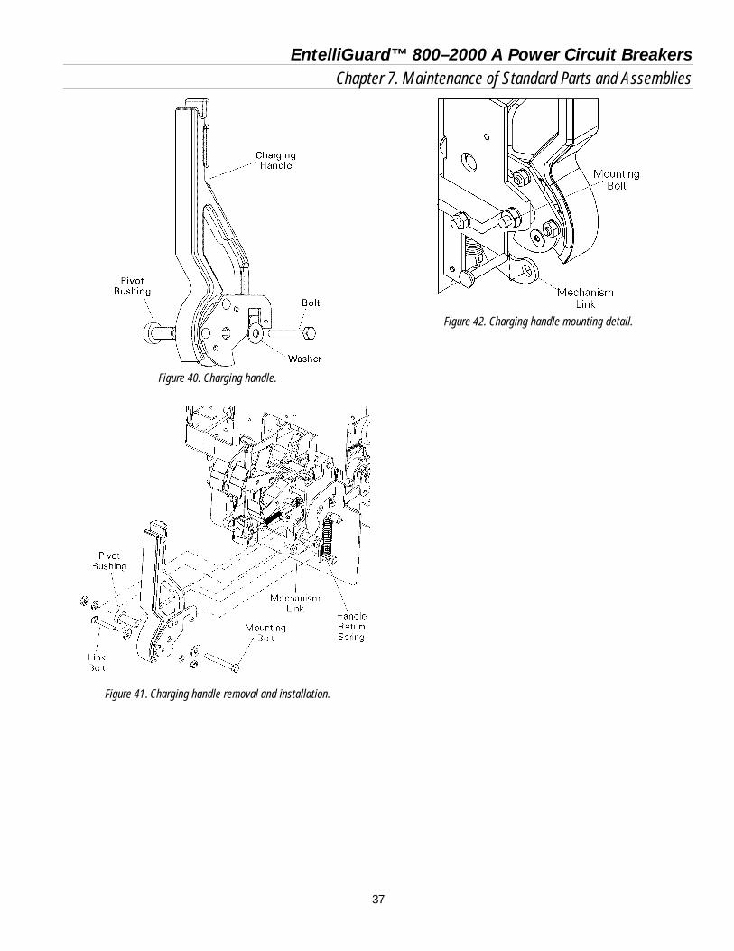
EntelliGuard™ 800–2000 A Power Circuit Breakers Chapter 7. Maintenance of Standard Parts and Assemblies
37
Figure 40. Charging handle.
Figure 41. Charging handle removal and installation.
Figure 42. Charging handle mounting detail.

EntelliGuard™ 800–2000 A Power Circuit Breakers Chapter 8. Accessory Maintenance
38
This section describes the removal, replacement, and adjustment of the various accessories available with EntelliGuard breakers. Before any of the operations in this chapter can be per-formed, the breaker must be removed from its compart-ment, as described in Section 5.2, and placed on a suitable work surface.
8.1 Bell Alarm with Lockout The Bell Alarm with Lockout locks out the breaker in the event of a protection trip. The device has one normally open output switch and a trip circuit that are connected to the secondary disconnect as illustrated in Figure 43. The switch output provides status feedback to the EntelliGuard Messenger. The Bell Alarm with Lockout can only be reset manually by pressing the yellow target/RESET button on the breaker escutcheon. Renewal parts for the Bell Alarm with Lockout are a complete kit including mounting hardware, illustrated in Figure 44, or the module only.
Removing the Bell Alarm with Lockout Use the following procedure to remove the Bell Alarm with Lockout module and mounting plate, as illustrated in Figure 45. If only the Bell Alarm module is to be replaced, it is not necessary to remove the mounting plate (perform steps 1–3 only).
1. Remove the breaker escutcheon, as described in Section 7.5.
2. Remove the four Bell Alarm wires from the secondary disconnect, as listed in Table 6. Cut the wire ties securing the wire bundle to the breaker frame so that the four wires can be removed with the Bell Alarm.
3. Remove the two screws and bushings securing the Bell Alarm module to the mounting plate and remove the module.
4. Remove the three nuts and lock washers securing the mounting plate to the breaker frame.
5. Disengage the mounting plate from the breaker mechanism and remove the plate.
Figure 43. Bell Alarm with Lockout connections to the secondary disconnect. The contact is shown in the RESET state.
Figure 44. Bell alarm with Lockout accessory kit.
Figure 45. Bell Alarm with Lockout installation or removal.
14
2
1 Lockout Trip Coil
6
16
4
3 Status Contact
19

EntelliGuard™ 800–2000 A Power Circuit Breakers Chapter 8. Accessory Maintenance
39
Connection
Wire Color
Sec. Disc. Terminal #
Lockout trip white 14 Lockout trip COM green 6 Status switch N/O blue 16 Status switch COM black 19
Table 6. Bell Alarm with Lockout wires and corresponding secondary disconnect terminals.
Installing the Bell Alarm with Lockout Use the following procedure to install the Bell Alarm with Lockout mounting plate and module. If this is a new installation into a breaker that was not equipped at the factory with a Bell Alarm with Lockout, see the installation instructions in DEH238, supplied with the Bell Alarm with Lockout kit. If only the module is to be replaced, begin at step 3.
1. Place the Bell Alarm mounting plate over the three standoffs on the breaker front frame and secure with three lock washers and nuts. Ensure that the actuating tab from the breaker mechanism engages the slot in the bottom of the mounting plate, as illustrated in the front view in Figure 46.
2. Line up the Bell Alarm module on the mounting plate, as shown in Figure 45, so that the solenoid plunger and locating pin fit in the appropriate holes. The label on the end of the module should appear as in Figure 47, with the legend ↑ SF LO (Small Frame Lockout) horizontal.
3. Attach the Bell Alarm module to the mounting bracket with the two screws provided.
4. Run the four wires from the Bell Alarm to the secon-dary disconnect A block and connect to the termi-nals listed in Table 6. Use wire ties to secure the wire bundle to the breaker frame.
5. Replace the breaker escutcheon, as described in Sec-tion 7.5.
Figure 46. Front view of the Bell Alarm with Lockout installation,
showing the breaker mechanism tab engaging the mounting plate slot.
Figure 47. Orientation of the label on the Bell Alarm module for
installation.
8.2 Shunt Trip The Shunt Trip allows the breaker to be opened remotely by the EntelliGuard Messenger™. It is always provided on electrically operated breakers. The device causes the circuit breaker to open when its coil is energized. An “A” auxiliary switch, which is closed when the breaker is closed, is connected in series with the Shunt Trip coil, as illustrated in Figure 48. The voltage source is connected to terminals 5 and 7 on the secondary disconnect. Renewal parts for the Shunt Trip are a complete kit, illus-trated in Figure 49, and the module. Electrical ratings for the Shunt Trip are listed in Table 7.
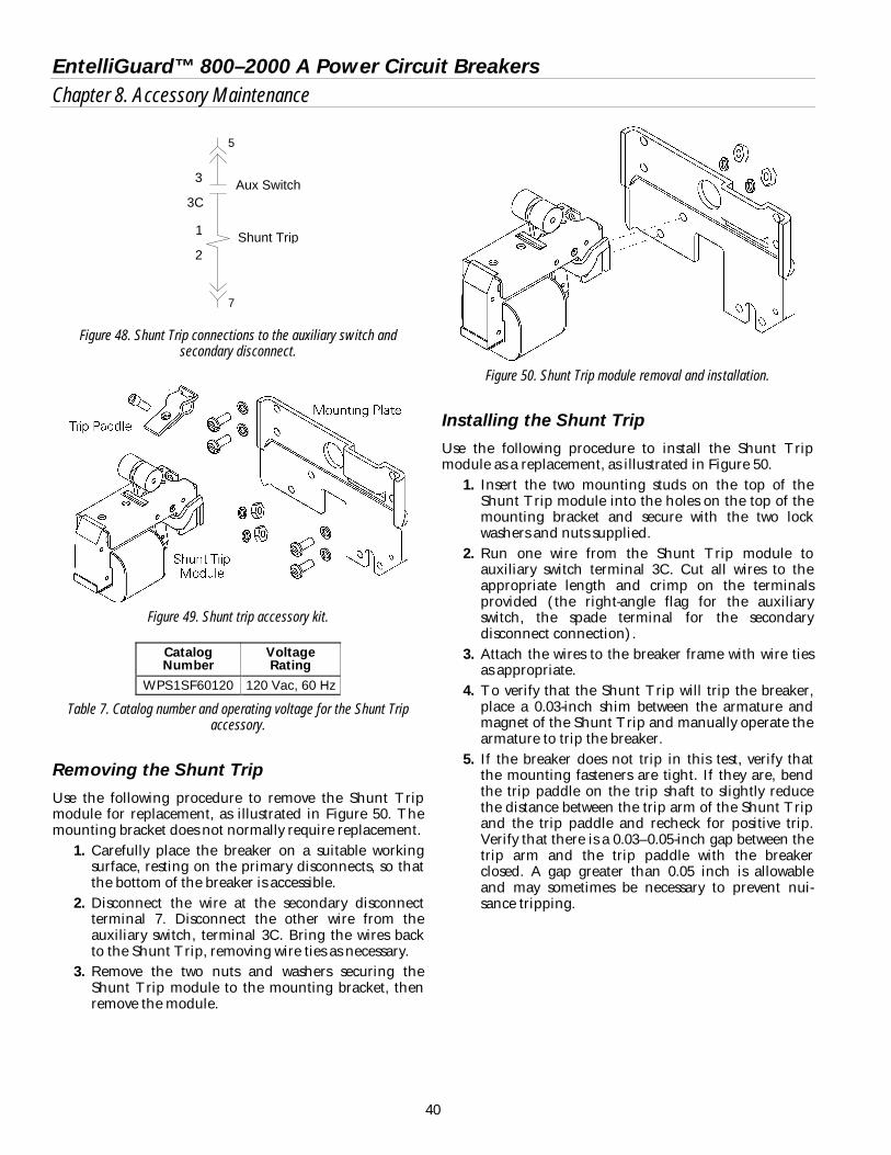
EntelliGuard™ 800–2000 A Power Circuit Breakers Chapter 8. Accessory Maintenance
40
Figure 48. Shunt Trip connections to the auxiliary switch and secondary disconnect.
Figure 49. Shunt trip accessory kit.
Catalog Number
Voltage Rating
WPS1SF60120 120 Vac, 60 Hz
Table 7. Catalog number and operating voltage for the Shunt Trip accessory.
Removing the Shunt Trip Use the following procedure to remove the Shunt Trip module for replacement, as illustrated in Figure 50. The mounting bracket does not normally require replacement.
1. Carefully place the breaker on a suitable working surface, resting on the primary disconnects, so that the bottom of the breaker is accessible.
2. Disconnect the wire at the secondary disconnect terminal 7. Disconnect the other wire from the auxiliary switch, terminal 3C. Bring the wires back to the Shunt Trip, removing wire ties as necessary.
3. Remove the two nuts and washers securing the Shunt Trip module to the mounting bracket, then remove the module.
Figure 50. Shunt Trip module removal and installation.
Installing the Shunt Trip Use the following procedure to install the Shunt Trip module as a replacement, as illustrated in Figure 50.
1. Insert the two mounting studs on the top of the Shunt Trip module into the holes on the top of the mounting bracket and secure with the two lock washers and nuts supplied.
2. Run one wire from the Shunt Trip module to auxiliary switch terminal 3C. Cut all wires to the appropriate length and crimp on the terminals provided (the right-angle flag for the auxiliary switch, the spade terminal for the secondary disconnect connection).
3. Attach the wires to the breaker frame with wire ties as appropriate.
4. To verify that the Shunt Trip will trip the breaker, place a 0.03-inch shim between the armature and magnet of the Shunt Trip and manually operate the armature to trip the breaker.
5. If the breaker does not trip in this test, verify that the mounting fasteners are tight. If they are, bend the trip paddle on the trip shaft to slightly reduce the distance between the trip arm of the Shunt Trip and the trip paddle and recheck for positive trip. Verify that there is a 0.03–0.05-inch gap between the trip arm and the trip paddle with the breaker closed. A gap greater than 0.05 inch is allowable and may sometimes be necessary to prevent nui-sance tripping.
5
7
Aux Switch 3C
3
2
1 Shunt Trip

EntelliGuard™ 800–2000 A Power Circuit Breakers Chapter 8. Accessory Maintenance
41
8.3 Charging Motor The Charging Motor provides a means of electrically charging the springs that close the breaker. The Charging Motor is available only as a factory-installed option. It is always provided on electrically operated breakers. The circuit breaker closing springs are charged automati-cally when control voltage is applied to terminals 8 and 17 of the secondary disconnects. When the springs are fully charged, a cutoff switch automatically de-energizes the motor. The closing springs will recharge automatically after the breaker closes. Renewal parts for the Charging Motor are the motor and the cut-off switch, illustrated in Figure 51. The catalog number and electrical characteristics of the Charging Motor are listed in Table 8.
Figure 51. Charging Motor and cut-off switch.
Catalog Number
Voltage Range, Vac
568B596G5 104–127
Table 8. Catalog number and operating voltage for the Charging Motor accessory.
Removing the Charging Motor Use the following procedure to remove the Charging Motor for replacement, as illustrated in Figure 52.
1. Carefully place the breaker on a suitable working surface, so that the right front of the breaker is accessible.
2. Disconnect the motor wires at the connector. 3. Remove the three bolts and lock washers securing
the motor to the breaker mechanism. 4. Remove the motor and the three mounting spacers.
Installing the Charging Motor Use the following procedure to install a replacement Charging Motor, as illustrated in Figure 52.
1. Place the motor in position with the three mounting spacers on the breaker mechanism and insert the three mounting bolts and lock washers. Tighten the bolts to 110 in-lb.
2. Connect the motor wires by plugging the connector into place.
Removing the Motor Cut-Off Switch Use the following procedure to remove the motor cut-off switch, as illustrated in Figure 52.
1. Carefully place the breaker on a suitable working surface, so that the right front of the breaker is accessible.
2. Remove the breaker escutcheon, as described in Section 7.5.
3. Disconnect the wires at the screw terminals on the switch.
4. Remove the nut from the switch stem under the hole in the mounting bracket.
5. Remove the cut-off switch.
Installing the Motor Cut-Off Switch Use the following procedure to install the replacement motor cut-off switch, as illustrated in Figure 52.
1. Screw one of the locking nuts onto the switch barrel and place the flat washer over the nut.
2. Place the cut-off switch in position with the switch stem through the hole in the mounting bracket. Attach the mounting nut and secure the switch.
3. Connect the wires at the screw terminals on the switch.

EntelliGuard™ 800–2000 A Power Circuit Breakers Chapter 8. Accessory Maintenance
42
Figure 52. Removal and installation of the Charging Motor and cut-off switch.

EntelliGuard™ 800–2000 A Power Circuit Breakers Chapter 8. Accessory Maintenance
43
Adjusting the Motor Cut-Off Switch Adjust the cut-off switch as illustrated in Figure 533:
1. Charge the closing springs with the manual charg-ing handle.
2. The main stem of the switch should be located between 0.005 and 0.030 inch from the barrel.
3. If necessary, adjust switch depression by screwing the switch button in or out of the threaded housing.
Figure 53. Cut-off switch adjustment.
8.4 Remote Close The Remote Close allows the breaker to be closed remotely by the EntelliGuard Messenger™ after the closing springs have been charged. It is always provided on electrically operated breakers. A circuit breaker equipped with the Remote Close acces-sory can be closed by applying the rated control voltage to terminals 9 and 18 of the secondary disconnects. The Remote Close accessory is continuously rated and has an antipump feature that prevents a motor-operated breaker from repeatedly closing if the closing signal is maintained. The closing control voltage must be removed for 1–2.5 seconds and then reapplied for each breaker closure. Renewal parts for the Remote Close are the complete kit, illustrated in Figure 54, the circuit board, and the sole-noid. Electrical characteristics of the Remote Close are listed in Table 9.
Figure 54. Remote Close accessory kit.
Catalog Number Voltage Rating WPRCSF60120 120 Vac, 60 Hz
Table 9. Catalog number and operating voltage for the Remote Close accessory.

EntelliGuard™ 800–2000 A Power Circuit Breakers Chapter 8. Accessory Maintenance
44
Removing the Remote Close Use the following procedure to remove the Remote Close solenoid and circuit board for replacement, as illustrated in Figure 55. If only the solenoid or circuit board is to be replaced, it is not necessary to remove both components.
1. Carefully place the breaker on a suitable working surface, resting on the primary disconnects, so that the bottom of the breaker is accessible.
2. Disconnect the two Remote Close wires at terminals 9 and 18 of the secondary disconnect. Cut the wire ties, as needed, so that the wires can be removed with the Remote Close.
3. Remove the two screws, lock washers, and flat wash-ers connecting the Remote Close module to the breaker frame.
4. Remove the snap ring connecting the Remote Close actuator to the pin on the charging mechanism and remove the module.
5. The Remote Close solenoid or circuit board can now be separately replaced on the module.
Installing the Remote Close Use the following procedure to install the replacement Remote Close, as illustrated in Figure 55. If this is a new installation into a breaker that was not equipped at the factory with a Remote Close, see the installation instructions in DEH172, supplied with the Remote Close kit. (The circuit breaker should be resting on the secondary disconnects with the right pole opening spring removed, as in the removal procedure above.)
1. Insert the connecting pin on the breaker closing mechanism through the hole in the end of the Remote Close actuator and secure with the snap ring.
2. Line up the mounting holes in the Remote Close module with the two tapped holes in the bottom of the breaker frame. Insert a screw with lock washer and flat washer into each hole and tighten.
3. Run the wires from the Remote Close module to the secondary disconnect and connect the wires to terminals 9 and 18. Attach the wires to the breaker frame with wire ties as needed.
Figure 55. Remote close installation and removal.
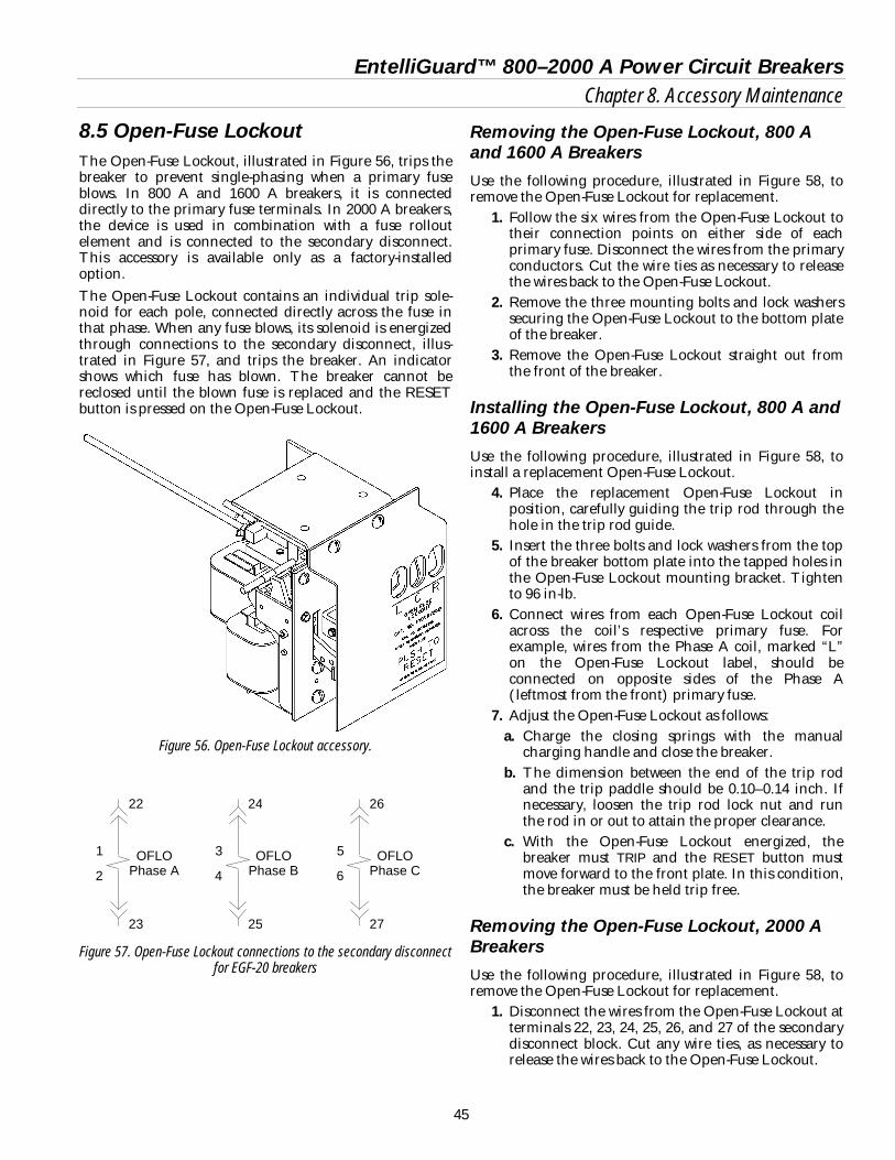
EntelliGuard™ 800–2000 A Power Circuit Breakers Chapter 8. Accessory Maintenance
45
8.5 Open-Fuse Lockout The Open-Fuse Lockout, illustrated in Figure 56, trips the breaker to prevent single-phasing when a primary fuse blows. In 800 A and 1600 A breakers, it is connected directly to the primary fuse terminals. In 2000 A breakers, the device is used in combination with a fuse rollout element and is connected to the secondary disconnect. This accessory is available only as a factory-installed option. The Open-Fuse Lockout contains an individual trip sole-noid for each pole, connected directly across the fuse in that phase. When any fuse blows, its solenoid is energized through connections to the secondary disconnect, illus-trated in Figure 57, and trips the breaker. An indicator shows which fuse has blown. The breaker cannot be reclosed until the blown fuse is replaced and the RESET button is pressed on the Open-Fuse Lockout.
Figure 56. Open-Fuse Lockout accessory.
Figure 57. Open-Fuse Lockout connections to the secondary disconnect for EGF-20 breakers
Removing the Open-Fuse Lockout, 800 A and 1600 A Breakers Use the following procedure, illustrated in Figure 58, to remove the Open-Fuse Lockout for replacement.
1. Follow the six wires from the Open-Fuse Lockout to their connection points on either side of each primary fuse. Disconnect the wires from the primary conductors. Cut the wire ties as necessary to release the wires back to the Open-Fuse Lockout.
2. Remove the three mounting bolts and lock washers securing the Open-Fuse Lockout to the bottom plate of the breaker.
3. Remove the Open-Fuse Lockout straight out from the front of the breaker.
Installing the Open-Fuse Lockout, 800 A and 1600 A Breakers Use the following procedure, illustrated in Figure 58, to install a replacement Open-Fuse Lockout.
4. Place the replacement Open-Fuse Lockout in position, carefully guiding the trip rod through the hole in the trip rod guide.
5. Insert the three bolts and lock washers from the top of the breaker bottom plate into the tapped holes in the Open-Fuse Lockout mounting bracket. Tighten to 96 in-lb.
6. Connect wires from each Open-Fuse Lockout coil across the coil’s respective primary fuse. For example, wires from the Phase A coil, marked “L” on the Open-Fuse Lockout label, should be connected on opposite sides of the Phase A (leftmost from the front) primary fuse.
7. Adjust the Open-Fuse Lockout as follows: a. Charge the closing springs with the manual
charging handle and close the breaker. b. The dimension between the end of the trip rod
and the trip paddle should be 0.10–0.14 inch. If necessary, loosen the trip rod lock nut and run the rod in or out to attain the proper clearance.
c. With the Open-Fuse Lockout energized, the breaker must TRIP and the RESET button must move forward to the front plate. In this condition, the breaker must be held trip free.
Removing the Open-Fuse Lockout, 2000 A Breakers Use the following procedure, illustrated in Figure 58, to remove the Open-Fuse Lockout for replacement.
1. Disconnect the wires from the Open-Fuse Lockout at terminals 22, 23, 24, 25, 26, and 27 of the secondary disconnect block. Cut any wire ties, as necessary to release the wires back to the Open-Fuse Lockout.
22
2
1
OFLO Phase A
23
24
4
3
OFLO Phase B
25
26
6
5
OFLO Phase C
27

EntelliGuard™ 800–2000 A Power Circuit Breakers Chapter 8. Accessory Maintenance
46
2. Remove the three mounting bolts and lock washers securing the Open-Fuse Lockout to the bottom plate of the breaker.
3. Remove the Open-Fuse Lockout straight out from the front of the breaker.
Installing the Open-Fuse Lockout, 2000 A Breakers Use the following procedure, illustrated in Figure 58, to install a replacement Open-Fuse Lockout.
1. Place the replacement Open-Fuse Lockout in position, carefully guiding the trip rod through the hole in the trip rod guide.
2. Insert the three bolts and lock washers from the top of the breaker bottom plate into the tapped holes in the Open-Fuse Lockout mounting bracket. Tighten to 96 in-lb.
3. Connect the wires from the coils on the Open-Fuse Lockout to the secondary disconnect block as fol-lows:
• Phase A to terminals 22 and 23. • Phase B to terminals 24 and 25. • Phase C to terminals 26 and 27.
4. Adjust the Open-Fuse Lockout as follows: a. Charge the closing springs with the manual
charging handle and close the breaker. b. The dimension between the end of the trip rod
and the trip paddle should be 0.10–0.14 inch. If necessary, loosen the trip rod lock nut and run the rod in or out to attain the proper clearance.
c. With the Open-Fuse Lockout energized, the breaker must TRIP and the RESET button must move forward to the front plate. In this condition, the breaker must be held trip free.
Figure 58. Open-fuse lockout installation and removal.

EntelliGuard™ 800–2000 A Power Circuit Breakers Chapter 8. Accessory Maintenance
47
8.6 Remote Charge-Indication Switch The remote charge-indication switch, illustrated in Figure 59, allows the EntelliGuard Messenger to remotely monitor the state of the closing springs on electrically operated breakers. When the springs are charged, terminals 3 and 4 at the secondary disconnect are shorted and are open when the springs are discharged.
Figure 59. Remote charge-indication switch.
Removing the Remote Charge-Indication Switch Use the following procedure to remove the remote charge-indication switch for replacement, as illustrated in Figure 60.
1. Remove the breaker escutcheon, as described in Section 7.5.
2. Disconnect the two wires from terminals 3 and 4 of the secondary disconnect block and bring them back to the switch.
3. Remove the bolt, lock washer, and flat washer attaching the switch to the flag shaft support plate, then slide off the switch.
Installing the Remote Charge-Indication Switch Use the following procedure to install the replacement remote charge-indication switch, as illustrated in Figure 60.
1. Place the replacement switch in position on the flag shaft. Insert the mounting bolt, lock washer, and flat washer through the rectangular hole in the switch and into the tapped hole in the flag shaft support plate. Do not tighten the bolt.
2. Adjust the switch position as follows:
a. Charge the breaker closing springs with the man-ual charging handle.
b. Rotate the switch until the switch trigger is fully depressed against the trigger pin, as illustrated in Figure 61.
c. Tighten the switch mounting bolt to 32 in-lb. d. Close and trip the breaker.
3. Run the two wires from the switch to the secondary disconnect block and connect them to terminals 3 and 4.
4. Replace the breaker escutcheon, as described in Sec-tion 7.5.
Figure 60. Remote charge-indication switch removal and installation.
Figure 61. Remote charge-indication switch side view.

EntelliGuard™ 800–2000 A Power Circuit Breakers Chapter 8. Accessory Maintenance
48
8.7 Network Interlock The Network Interlock provides a means of locking out a breaker to coordinate its operation with other breakers in the distribution network. When activated by the EntelliGuard Messenger, the Network Interlock prevents the breaker from closing. When the EntelliGuard Messenger issues a RESET signal, the breaker can be closed either remotely or locally. The Network Interlock accessory includes a manual reset lever to reset the device in the absence of a signal from the EntelliGuard Messenger. The Network Interlock consists of a trip coil, a reset coil, and a status switch. The device connections to the secondary disconnect are shown in Figure 62. When voltage is applied across the trip coil, the device locks out the breaker. Conversely, when voltage is applied to the reset coil or when the reset lever is depressed, the Network Interlock resets, allowing the breaker to close. The Network Interlock does not close the breaker itself. Renewal parts for the Network Interlock are available as a complete kit or as a module only. The Network Interlock accessory is only available on electrically operated breakers.
Figure 62. Network Interlock connections to the secondary disconnect.
Removing the Network Interlock Module Use the following procedure to remove the Network Interlock.
1. Disconnect the six wires from the Network Interlock device. Label each wire as it is removed. Cut wire ties as necessary.
2. Remove the manual reset assembly by removing the two hex-head screws as shown in Figure 65.
3. Remove the accessory mounting plate as shown in Figure 63.
4. Remove the Network Interlock module from the mounting plate by removing the three sets of nuts and washers, as shown in Figure 64.
Installing the Network Interlock Module Use the following procedure to install the Network Interlock module as a replacement. 1. Open the circuit breaker and remove it from the
cubicle or substructure. Check to ensure the breaker closing springs are DISCHARGED.
2. Carefully place the circuit breaker on a suitable working surface, resting on the primary disconnects, so that the bottom of the circuit breaker is accessible.
3. Fasten the Network Interlock module to the accessory mounting plate using three sets of # 8-32 nuts, spring washers, and flat washers as shown in Figure 64.
4. Fasten the Shunt Trip accessory to the mounting plate beside the Network Interlock. See Section 8.2 or DEH-168 for detailed instructions.
5. Assemble the accessory mounting plate to the circuit breaker frame using four sets of # 10-32 screws, spring washers, and flat washers as shown in Figure 63
6. Ensure the Network Interlock is in the RESET state (shown in Figure 66) by manually rotating the reset lever counterclockwise. If the Network Interlock was SET, this operation will cause the set lever to retract (counterclockwise) away from the trip paddle.
7. With the breaker open, charge the breaker closing springs. Do not close the breaker. Adjust the gap between the Network Interlock set lever and trip paddle by rotating the socket-head adjusting screw as shown in Figure 66. The distance between the set lever and the trip paddle must be between 0.060 and 0.090 inch.
8. Connect the six wires to their corresponding terminals on the Network Interlock device.
9. Reset the Network Interlock by pushing the manual reset button. The Network Interlock status circuit should be open. Close the breaker manually or electrically. The breaker should close properly.
10. Set the Network Interlock by applying 120 VAC across terminals 15 and 21 on the secondary disconnect. The breaker should trip open and the status circuit should change from open to close.
11. Charge the breaker manually or electrically. Close the breaker. The breaker should trip open, discharging the closing springs.
12. Reset the Network Interlock by applying 120 VAC across terminals 20 and 21 on the secondary disconnect. The status circuit should change from closed to open.
13. Charge and close the breaker. The breaker should close properly.
14. Set the Network Interlock, and repeat Steps 9 through 13.
15
NI Set Coil
20
21
NI Reset Coil
1
3
2
16
19
4
5
NI Status Contact

EntelliGuard™ 800–2000 A Power Circuit Breakers Chapter 8. Accessory Maintenance
49
Figure 63. Network Interlock assembly mounting to the circuit breaker bottom frame. (Shunt Trip omitted for clarity.)
Figure 64. Network Interlock module fastening to the mounting plate.
Figure 65. Manual reset assembly mounting
Figure 66. Trip paddle and set lever gap calibration. (Breaker charged. NI module shown in RESET position.)
Manual Reset Assembly
Manual Reset Button
0.06” - 0.09”
Reset Lever
Set Lever
Trip Paddle
Adjusting Screw
Bottom Frame
Mounting Plate
Reset Solenoid
Set Solenoid

EntelliGuard™ 800–2000 A Power Circuit Breakers Notes
50

EntelliGuard™ 800–2000 A Power Circuit Breakers Notes
51

EntelliGuard™ 800–2000 A Power Circuit Breakers Notes
52

EntelliGuard™ 800–2000 A Power Circuit Breakers Notes
53

g GE Consumer & Industrial General Electric Company 41 Woodford Avenue, Plainville, CT 06062
DEH203 R02 1005 © 2005 General Electric Company
Related Documents