CHAPTER 11 PARA NO. CONTENTS PAGE NO. 11.0 INTRODUCTION 01 11.1 ROOF MOUNTED AC PACKAGE UNIT 01 11.1.1 General 01 11.1.2 Refrigerant Pipe Line/ Capillary 04 11.1.3 Compressors 04 11.1.4 Condenser Fans Motor/ Blades and Blower Motor/ Impeller 05 11.1.5 Return/ Fresh Air Filters 06 11.1.6 HP/ LP/ OHP Cutout Switch 06 11.1.7 Heater 07 11.1.9 Expansion Valve/ Capillary Tubes 08 11.1.10 Evaporator Coil 08 11.1.11 Filter Drier & Sight Glass 08 11.1.12 Access Doors 09 11.1.13 Drip Tray 09 11.1.14 Condenser Area 09 11.1.15 Microprocessor Controller 09 11.2 INTERNAL FITTINGS 09 11.3 BATTERY 10 11.4 BATTERY CHARGER 11 11.5 STEP DOWN TRANSFORMER 60 kVA 11 11.6 LIGHTING TRANSFORMER 1 kVA 11` 11.7 SWITCH BOARD CABINET 12 11.8 MISCELLANEOUS EQUIPMENT 13 11.9 MAIN PANTRY ITEMS 14 11.10 MINI PANTRY ITEMS (DEEP FREEZER, BOTTLE 16 COOLER, HOT CASE) 11.11 WORK INSTRUCTIONS FOR SHOP SCHEDULE SS-1 17 11.11.1 Pre-Inspection 17 11.11.2 Dusting 17 11.11.3 Final Testing 17 11.11.4 Final Joint Inspection 18

Welcome message from author
This document is posted to help you gain knowledge. Please leave a comment to let me know what you think about it! Share it to your friends and learn new things together.
Transcript

Maintenance Manual of LHB Coaches Electrical Maintenance Schedules
Chapter 11 Page 1 of 65
CHAPTER 11
PARA NO. CONTENTS PAGE NO. 11.0 INTRODUCTION 01 11.1 ROOF MOUNTED AC PACKAGE UNIT 01
11.1.1 General 01
11.1.2 Refrigerant Pipe Line/ Capillary 04
11.1.3 Compressors 04
11.1.4 Condenser Fans Motor/ Blades and Blower Motor/ Impeller 05
11.1.5 Return/ Fresh Air Filters 06
11.1.6 HP/ LP/ OHP Cutout Switch 06
11.1.7 Heater 07
11.1.8 NTC sensors 07
11.1.9 Expansion Valve/ Capillary Tubes 08
11.1.10 Evaporator Coil 08
11.1.11 Filter Drier & Sight Glass 08
11.1.12 Access Doors 09
11.1.13 Drip Tray 09
11.1.14 Condenser Area 09
11.1.15 Microprocessor Controller 09 11.2 INTERNAL FITTINGS 09
11.3 BATTERY 10
11.4 BATTERY CHARGER 11
11.5 STEP DOWN TRANSFORMER 60 kVA 11
11.6 LIGHTING TRANSFORMER 1 kVA 11`
11.7 SWITCH BOARD CABINET 12
11.8 MISCELLANEOUS EQUIPMENT 13
11.9 MAIN PANTRY ITEMS 14
11.10 MINI PANTRY ITEMS (DEEP FREEZER, BOTTLE 16 COOLER, HOT CASE)
11.11 WORK INSTRUCTIONS FOR SHOP SCHEDULE SS-1 17
11.11.1 Pre-Inspection 17
11.11.2 Dusting 17
11.11.3 Final Testing 17
11.11.4 Final Joint Inspection 18
a
Text Box
Go to Main Index

Maintenance Manual of LHB Coaches Electrical Maintenance Schedules
Chapter 11 Page 2 of 65
PARA NO. CONTENTS PAGE NO. 11.12 WORK INSTRUCTIONS FOR SHOP SCHEDULE SS-2 19
11.12.1 Pre-Inspection 19
11.12.2 Dusting 19
11.12.3 Striping 19
11.12.4 Equipping 19
11.12.5 Final Testing 19
11.12.6 Final Joint Inspection 20
11.13 TROUBLE SHOOTING OF LHB TYPE EOG COACH 21
11.13.1 Details of Input & Output Connections of AC Compact Controller 21
11.13.2 Air Conditioning Unit not Working 23
11.13.3 Coach Supply not Getting ‘ON’ 25
11.13.4 Non-functioning of Battery Charger 26
11.13.5 Defect in Lighting System (Lights not getting ON) 26
11.13.6 Frequent Tripping of Supply in Coach 27
11.13.7 If AC Control MCB (F-35) Trips 27
11.13.8 No Water in Coach 28
11.14 TROUBLE SHOOTING OF LHB TYPE GENERATOR CAR 29
11.14.1 Engine not Starting 29
11.14.2 ACB not getting ON 29
11.14.3 Feeder Contactor not getting ON 29
11.14.4 Bus Coupler not getting ON 29
11.14.5 Safety Loop not getting ON 29
11.14.6 Main Battery Charger not getting ON 29
11.14.7 Main Battery Charger ON but battery not charging 29
11.14.8 Emergency Battery Charger not switching ON in case 30 of Main Battery Charger defective
11.14.9 110V AC Lights not getting ON 30
11.14.10 Emergency Lights not getting ON 30
11.14.11 Transformer contactor not getting ON 30
11.14.12 415V Main contactor (K-44) not getting ON 30
ANNEXURES ANNEXURE 11.1 - ELECTRICAL TEST REPORT FOR AC COACHES AFTER SS-I 31
ANNEXURE 11.2 - PROFORMA FOR RECORD OF PRE-COOLING TEST 34

Maintenance Manual of LHB Coaches Electrical Maintenance Schedules
Chapter 11 Page 3 of 65
PARA NO. CONTENTS PAGE NO.
ANNEXURE 11.3 - ELECTRICAL TEST REPORT FOR AC COACHES AFTER SS-II 35
ANNEXURE 11.4 - SAMPLE CALCULATION FOR CALCULATING COMPENSATING LOAD 39
ANNEXURE 11.5 - PROFORMA TO RECORD PULL DOWN TEST 41
ANNEXURE 11.6 - FINAL JOINT INSPECTION REPORT OF LHB EOG AC COACHES 42
ANNEXURE 11.7- LIST OF MUST CHANGE ITEMS FOR LHB AC COACHES 47
ANNEXURE 11.8- PHOTOGRAPHES OF MUST CHANGE ITEMS FOR LHB AC COACHES 49
ANNEXURE 11.9- ELECTRICAL TOOLS, MACHINES & PLANT 60
a
Text Box
Go to top Go to main Index
Maintenance Manual of LHB Coaches Electrical Maintenance Schedules
Chapter 11 Page 1 of 65
CHAPTER 11
ELECTRICAL MAINTENANCE SCHEDULES
11.0 INTRODUCTION
The LHB design of AC coaches is quite different from ICF design AC coaches. The maintenance practices for these coaches are also different. The various maintenance schedules and their periodicity are mentioned below:
Periodic Maintenance Schedules
Schedule D1 : Trip / Weekly
Schedule D2 : Three monthly ± 3days
Schedule D3 : Half Yearly ± 15 days
Shop Schedule (SS-1), IOH : 18 Months / 6 Lakh kms whichever is earlier
Shop Schedule (SS-2), POH : 36 Months / 12 Lakh kms whichever is earlier
The EOG, LHB rake mainly comprises of AC coaches, power cars and pantry cars.
The electrical equipment of this rake have been described in chapters 6, 7 and 8 of this manual. The equipment wise maintenance activities of above schedules and work instructions for SS-1 and SS-2 are described in this chapter.
11.1 ROOF MOUNTED AC PACKAGE UNIT
As per RDSO’s Maintenance Schedule No. RDSO/PE/SMI/AC/0044-2011 (Rev.0) dated 02/04.11.2011, following maintenance activities to be carried out on roof mounted AC package unit of LHB design coaches:
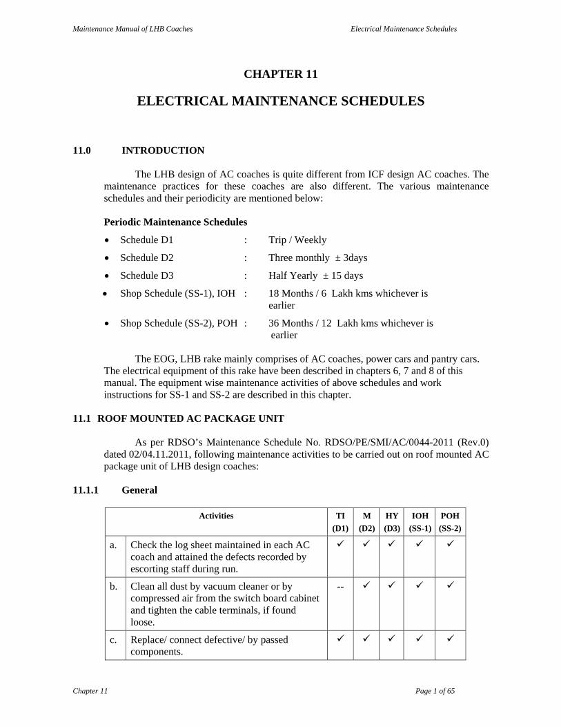
11.1.1 General
Activities TI
(D1)
M
(D2)
HY
(D3)
IOH
(SS-1)
POH
(SS-2)
a. Check the log sheet maintained in each AC coach and attained the defects recorded by escorting staff during run.
b. Clean all dust by vacuum cleaner or by compressed air from the switch board cabinet and tighten the cable terminals, if found loose.
--
c. Replace/ connect defective/ by passed components.

Maintenance Manual of LHB Coaches Electrical Maintenance Schedules
Chapter 11 Page 2 of 65
Activities TI
(D1)
M
(D2)
HY
(D3)
IOH
(SS-1)
POH
(SS-2)
d. Remove fresh and return air filters by opening the access doors of the unit. Clean these filters with vacuum cleaner or by compressed air after taking out the filters and place them gently in their places or replace with pre-cleaned/ new filter/ filter media and close the doors properly. A cleaning jig should be available with AMC holders/ Railways for this activity.
Note: After this activity, the service doors shall be latched properly in case of return air filter. Similarly, the fresh air grill shall be positioned and locked properly.
To
be r
epla
ced
To
be r
epla
ced
e. Check looseness of microprocessor’s input/ output connections.
f. Check that the microprocessor controller is firmly mounted.
g. Check analogue type pressure gauges for their working provided on switch board panel.
h. Check working of rotary switches by rotating forward and backward, provided on switch board panel for temperature selection and air control ON. Replace if required.
i. Check working of set point generator rotary switch provided for temperature setting.
j. Check the tripping of heaters i.e. OHP. The OHP setting is 65°C. The testing of OHP setting shall be done by switching off the blower. During testing, the probe of digital thermometer shall be placed near the sensor of OHP & the display shall be kept outside.
Note : It shall be checked twice a year. In addition, it shall also be checked as a pre-winter precaution before the onset of winter season.
-- --
k. Check whether ESTI cartridge is provided with bulb and properly screwed.
Note : It shall be checked twice a year, in addition, it shall also be checked as a pre-winter precaution before the onset of winter season.
-- --

Maintenance Manual of LHB Coaches Electrical Maintenance Schedules
Chapter 11 Page 3 of 65
Activities TI
(D1)
M
(D2)
HY
(D3)
IOH
(SS-1)
POH
(SS-2)
l. Run the plant for half an hour and then check the current drawn by various equipment with the help of clamp tester (tongue tester) duly calibrated.
Normal currents for various equipments and mode of operation are as under:
Package unit in cooling mode
20-23 Amps.
Compressor
07-10Amps
Condenser fan motor
1.5 – 2.1 Amps.
Blower motor
1.5-2.5 Amps
Package unit in heating mode
07-11 Amps.
Note: The current also depends on the ambient temperature.
-- --
m. Check visually condenser fan blade and ensure that there is no crack on the blade or hub.
--
n. Check and tighten mountings of blower, compressor and blower motors and ensure that they are in good condition.
-- --
o. Ensure that no capillary tubes are in hanging position.
--
p. Check capillary tubes provided for HP/LP cutout for proper support/ clamping. Their nuts should be properly tightened.
--
q. Check for proper tightening of cover provided over evaporator compartment.
-- --
r. Check that earthing shunts in RMPU are provided. Earthing shunts should be earthed with coach body.
-- --
To
be
repl
aced
s. Check canvas duct provided at return & supply air. Rectify or replace the same, if torn or damaged.
-- --
To
be
repl
aced
To
be
repl
aced
t. Run the plant in conjunction with microprocessor controller and observe for any abnormality.

Maintenance Manual of LHB Coaches Electrical Maintenance Schedules
Chapter 11 Page 4 of 65
Activities TI (D1)
M (D2)
HY (D3)
IOH (SS-1)
POH (SS-2)
u. Check anti-vibration mountings of compressors, condenser motors, blower motor and over all package unit. Replace if required.
-- -- AVM forover all package unit to bereplaced
v. If less cooling is noticed, check the leakage of refrigerant from the system by using soap solution or leak detector. If leak is detected, it should be attended and re-charging of refrigerant in the system shall be made as per RDSO’s SMI ELPS/AC/SMI/14.
-- --
w. Check insulation resistance of all the motors & compressors by the duly calibrated 1000V megger. Attend the motors, if insulation resistance of motor is found less than 2M ohm.
Important: Disconnect microprocessor controller during this activity.
-- -- --
x. Check for physically damaged/ jointed cables. Replace if needed.
-- -- --
y. Check for the physically damaged conduits. Replace them, if needed.
-- -- -- To be replaced
z. Check for proper working of servo drive. -- --
z(i) Harting connector to be replaced -- -- --
11.1.2 Refrigerant Pipe Line/ Capillary
Activities TI (D1)
M (D2)
HY (D3)
IOH (SS-1)
POH (SS-2)
a. Check for proper clamping/ support. -- -- --
b. Check for rubbing of capillary with SS sheet/ channel or other parts of RMPU.
-- -- --
c. Check leakage from flare nut of HP/ LP cutouts with soap solution.
-- --
d. Check leakage from feeler tube of OHP. -- -- --
11.1.3 Compressors
Activities TI (D1)
M (D2)
HY (D3)
IOH (SS-1)
POH (SS-2)
a. Check and ensure holding clamps from top are properly tightened.
-- --
b. Check and ensure mounting fastenings are properly tightened.
-- --
c. Check leakage from suction & discharge port.
-- --
d. Check Accumulator holding/ mounting, if provided.
-- --

Maintenance Manual of LHB Coaches Electrical Maintenance Schedules
Chapter 11 Page 5 of 65
Activities TI
(D1) M
(D2)HY (D3)
IOH (SS-1)
POH (SS-2)
e. Ensure condensing area covers are properly tightened & not touching top of compressor body.
-- --
f. Check electrical terminal box is properly tightened & cables are terminated with lugs.
-- --
11.1.4 Condenser Fans Motor/ Blades and Blower Motor/ Impeller
Activities TI
(D1)
M
(D2)
HY
(D3)
IOH
(SS-1)
POH
(SS-2)
a. Check and ensure mounting fasteners are properly tightened.
-- --
b. Check electrical terminal box of motors is properly tightened & cables are terminated with lugs.
-- --
c. Ensure double earthing shunts are provided. -- -- To be replaced during POH
d. Check condition of blade for its fixing/ cracking/ breakage/ damage or touching with its cover. Rectify/ replace, if needed.
-- --
e. Ensure proper clamping of cable conduits. -- --
f. Overhauling of Blower and condenser fan motors shall includes the following during POH.
The incoming motors shall be checked for abnormal noise and vibration.
Check bearing make and replace with specified make, if found defective.
The IR value of motor stator shall be measured between motor terminal and frame before and after overhauling. The value of IR shall not be less than 10 M, when measured with 1000 volt megger.
Winding resistance of motors shall be measured between RY, YB & BR phases. The winding resistance shall be ± 10% of resistance declared by OEM in cold condition.
Check closely terminal block and connecting lead for any physical damage or any flash mark over it. Replace the same, if not satisfactory.
-- -- -- --

Maintenance Manual of LHB Coaches Electrical Maintenance Schedules
Chapter 11 Page 6 of 65
Activities TI
(D1)
M
(D2)
HY
(D3)
IOH
(SS-1)
POH
(SS-2)
Perform HV (Di-electric test) on stator by applying 1.5 kV AC supply for one minute. During test the leakage current shall also be measured, which shall not be more than 1.0 mA.
Run motor on no load for 15 minutes and check the following.
i. Bearing noise – Normal noise.
ii. Bearing temperature rise above ambient
should not be more than 10°C.
iii. SPM reading – 20dB max.
(Green zone)
Measure starting current of motors on no load. It shall not be more than 10 times of normal running current. Similarly, the running current of motors shall be measured and it shall not be more than 1.4A.
Spray water over running motor by jet having 10mm dia from all side. After spray, check IR value. There should be no drop in IR value.
Ensure the continuity of TOP.
Anti tracking varnish
g. Ensure that impellers are properly tightened. -- --
h. Ensure electrical terminal box is properly tightened & cables are terminated with lug.
-- --
11.1.5 Return/ Fresh Air Filters
Activities TI
(D1)
M
(D2)
HY
(D3)
IOH
(SS-1)
POH
(SS-2)
a. Ensure that filters are not damaged.
b. Ensure that there is a provision to avoid wrong fitment in the filter as well as in RMPU.
-- -- --
c. Filter media to be replaced --- --- -- ---
d. Complete filter shall be replaced -- -- -- ---

Maintenance Manual of LHB Coaches Electrical Maintenance Schedules
Chapter 11 Page 7 of 65
11.1.6 HP/ LP/ OHP Cutout Switch
Activities TI (D1)
M (D2)
HY (D3)
IOH (SS-1)
POH (SS-2)
a. Check that the mounting fasteners are properly tightened.
-- --
b. Ensure proper clamping/ support of capillary tube connected to HP/ LP/ OHP cutout switch.
-- --
c. Ensure that flare nuts are properly tightened. -- --
d. Ensure that control wires to HP/ LP/ OHP cutout switches are properly clamped.
-- --
e. Ensure that covers of these HP/ LP/ OHP cutout switch are properly screwed.
---
f. Ensure proper clamping of feeler tube of OHP switch.
-- -- --
g. Remove the accumulated dust over feeler tube of OHP switch.
-- --
h. There should be a cover (canopy) on top HP/ LP switch (provided with capillary tubes) to prevent water entry.
--
11.1.7 Heater
Activities TI (D1)
M (D2)
HY (D3)
IOH (SS-1)
POH (SS-2)
a. Ensure proper mounting of heater. -- --
b. Ensure proper clamping of electrical wires to heater.
-- --
c. Check dust accumulation on heating element. Remove gently, if required.
-- --
11.1.8 NTC sensors
Activities TI (D1)
M (D2)
HY (D3)
IOH (SS-1)
POH (SS-2)
a. Ensure that the sensors provided at return air path, fresh air and supply air are firmly mounted.
-- --
b. Ensure sensor wires are properly clamped. -- --
c. Remove the dust accumulated over sensor gently.
-- --

Maintenance Manual of LHB Coaches Electrical Maintenance Schedules
Chapter 11 Page 8 of 65
11.1.9 Expansion Valve/ Capillary Tubes
Activities TI
(D1)
M
(D2)
HY
(D3)
IOH
(SS-1)
POH
(SS-2)
a. Ensure that the bulb is mounted in the suction line just after evaporator coil and in a position corresponding to between 1 O’clock and 4 O’ clock. Ensure that it is properly insulated.
--
b. Ensure that the equalizing line is connected in the suction line immediately after the bulb.
-- --
c. Ensure that the bulb is not connected at the bottom of the pipe line.
-- --
d. Ensure that bulb/ equalizing line/ capillary tubes are not chocked.
--
11.1.10 Evaporator Coil
Activities TI (D1)
M (D2)
HY (D3)
IOH (SS-1)
POH (SS-2)
a. Ensure that there is no damage to fins. -- -- --
b. Ensure that capillaries of distributors to evaporator coil are not having any sharp bend or kinks. They should also be clamped properly.
-- -- --
c. Ensure that air passes only through evaporator coils and no air is bypassed directly to blower chamber.
-- -- --
d. Clean the coil, if found dirty. (i) cleaning through blower in D2. (ii) Cleaning through water jet in D3.
--
e. Check that the mounting fasteners are properly tightened.
-- -- --
11.1.11 Filter Drier & Sight Glass
Activities TI (D1)
M (D2)
HY (D3)
IOH (SS-1)
POH (SS-2)
a. Ensure that drier is installed with flow in the direction of the arrow marked on the filter drier label.
-- -- --
NOTE : 1. Never use “Antifreeze liquids” like methyl alcohol together with a filter
drier. Such liquid can damage the filter. 2. Never re-use a filter drier. 3. To avoid chances of moisture ingress in the system, filter drier &
compressor should be installed immediately after evacuation and charging the system.

Maintenance Manual of LHB Coaches Electrical Maintenance Schedules
Chapter 11 Page 9 of 65
11.1.12 Access Doors
Activities TI (D1)
M (D2)
HY (D3)
IOH (SS-1)
POH (SS-2)
a. Insulate service doors, lower portion and side wall from inside of the evaporator compartment.
-- -- --
b. Ensure that the latches to lock the service doors are not defective/ damaged.
c. Check and replace thermal insulation -- -- --
11.1.13 Drip Tray
Activities TI (D1)
M (D2)
HY (D3)
IOH (SS-1)
POH (SS-2)
a. Ensure that there is no leakage of condensate water from drip tray to electrical box & blower housing area.
-- --
b. Ensure free flow of condensate water. --
11.1.14 Condenser Area
Activities TI (D1)
M (D2)
HY (D3)
IOH (SS-1)
POH (SS-2)
a. Clean the condenser coil from inside with compressed air/ water jet after opening the cover of condenser area.
--
b. Ensure that there is no damage to fins. -- --
c. Check that the mounting fasteners are properly tightened.
-- -- --
d. Provide fire retardant thermal insulation over suction line.
-- -- -- ---
e. Ensure that there is no damage/ crack in structure frame of RMPU.
-- -- --
f. Ensure proper clamping of electrical conduit. -- -- --
11.1.15 Microprocessor Controller
Activities TI (D1)
M (D2)
HY (D3)
IOH (SS-1)
POH (SS-2)
a. Check control logic of microprocessor controller on simulating kit.
-- -- -- --
11.2 INTERNAL FITTINGS
Activities TI (D1)
M (D2)
HY (D3)
IOH (SS-1)
POH (SS-2)
a. Check visually for any damages. b. Check lights and emergency light system for
proper functioning and replace defective lights.

Maintenance Manual of LHB Coaches Electrical Maintenance Schedules
Chapter 11 Page 10 of 65
Activities TI (D1)
M (D2)
HY (D3)
IOH (SS-1)
POH (SS-2)
c. Check and clean lamp shades/ covers -- d. Replace broken diffusers, reflectors,
defective invertors and holders -- -- --
e. All shortages are to be replenished -- -- --
11.3 BATTERY
Activities TI (D1)
M (D2)
HY (D3)
IOH (SS-1)
POH (SS-2)
a.
Check visually battery boxes and suspension for any damage or irregularity
b. Check container and inter-cell connections and clean, if necessary.
--
c. Check battery connections for tightness -- --
d. Clean battery connections and apply petroleum jelly or Vaseline
-- --
e. Remove the batteries from battery boxes. -- -- --
f. Clean and repair battery boxes and repaint with anti corrosive epoxy based paint.
-- -- --
g. Clean thoroughly corrosion/ sulphation of inter-cell connectors etc. and protect them from further corrosion by applying petroleum jelly or vase-line. Change cell connectors and fasteners on condition basis.
-- -- --
h. Record lug date to determine the life of the battery
-- -- --
i. Charge the battery fully till 3 constant hourly readings of voltage indicates the conditions of a fully charged cell.
-- -- --
j. Tighten the safety vent plugs if found loose. -- -- --
Carry out the capacity test Charge the battery fully till 3 constant
hourly readings of voltage indicates the condition of a fully charged cell.
Discharge the battery at 10 hours discharge rate. While discharging, record the voltage.
Record the capacity of the battery during discharge. It should not be less than 80% of the rated capacity.
-- -- -- --
k. In case while discharging, any of the cell’s voltage falls below 1.75 V within 08 hours disconnect the cell from the circuit for treatment with 01 or 02 cycles of slow charge & discharge as per manufacturers maintenance manual.
-- -- -- --
Maintenance Manual of LHB Coaches Electrical Maintenance Schedules
Chapter 11 Page 11 of 65
l. After 2 cycles of charge & discharge, recharge the cells fully.
-- -- -- --
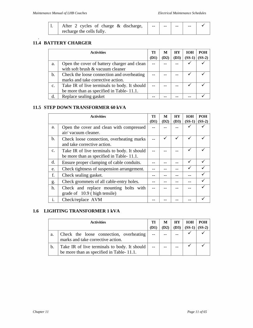
. 11.4 BATTERY CHARGER
Activities TI (D1)
M (D2)
HY (D3)
IOH (SS-1)
POH (SS-2)
a.
Open the cover of battery charger and clean with soft brush & vacuum cleaner
-- --
--
b. Check the loose connection and overheating marks and take corrective action.
-- -- --
c. Take IR of live terminals to body. It should be more than as specified in Table- 11.1.
-- -- --
d. Replace sealing gasket -- -- -- --
11.5 STEP DOWN TRANSFORMER 60 kVA
Activities TI (D1)
M (D2)
HY (D3)
IOH (SS-1)
POH (SS-2)
a.
Open the cover and clean with compressed air/ vacuum cleaner.
-- -- --
b. Check loose connection, overheating marks and take corrective action.
--
c. Take IR of live terminals to body. It should be more than as specified in Table- 11.1.
-- -- --
d. Ensure proper clamping of cable conduits. -- -- --
e. Check tightness of suspension arrangement. -- -- --
f. Check sealing gasket. -- -- -- --
g. Check grommets of all cable-entry holes. -- -- -- --
h. Check and replace mounting bolts with grade of 10.9 ( high tensile)
-- -- -- --
i. Check/replace AVM -- -- -- --
1.6 LIGHTING TRANSFORMER 1 kVA
Activities TI (D1)
M (D2)
HY (D3)
IOH (SS-1)
POH (SS-2)
a. Check the loose connection, overheating marks and take corrective action.
-- -- --
b. Take IR of live terminals to body. It should be more than as specified in Table- 11.1.
-- -- --

Maintenance Manual of LHB Coaches Electrical Maintenance Schedules
Chapter 11 Page 12 of 65
11.7 SWITCH BOARD CABINET
Activities TI
(D1)
M
(D2)
HY
(D3)
IOH
(SS-1)
POH
(SS-2)
a. Clean the panel with blower and vacuum cleaner and check for any loose connections.
--
b. Ensure all cable entry holes are provided with grommets
-- -- --
c. Check the contacts of power contactors and other contactors.
-- -- --
d. Check the connection of switchgear terminals blocks for overheating and tightness.
-- -- --
e. Check the fixation and terminal connections of microcontroller.
-- -- --
f. Check rotary switch for proper working. -- -- --
g. Check all the earthing shunts and replace, if required.
-- -- --
h. Check the working of gauges, voltmeters and ammeters.
-- -- --
i. Take IR of live terminals to body for power and control supply. It should be more than as specified in Table- 11.1
-- -- --
j. Check cabinet doors for proper closing and locking.
k. Check the door locks and hinges also.
l Replace MCBs for pantry equipment, pumps & Compressor.
-- -- -- --
m Check condition of contracts by measuring the contact area, mili volt drop etc.. Replace them on condition basis if fails in test.
-- -- -- --
n Replace disconnecting & earthing device complete rotary switch.
-- -- -- --
o Replace open type control fuse unit for HT circuit with fuse base holder assembly unit.
-- -- -- --
p Ensure provision of fuse/MCB safety protection in DC to DC convertor circuit
-- -- -- --
q Ensure working of MMRs (750Volts & 415Volts) & their replacement with new ones
-- -- -- --
r Replace defective MVRs. -- -- -- --
s Replace contactors for compressors & K-44. -- -- -- --
t Replace defective/ bypassed electronic module for contactors.
-- -- -- --
Maintenance Manual of LHB Coaches Electrical Maintenance Schedules
Chapter 11 Page 13 of 65
u Replace all defective/bypassed Microprocessor with latest universal type Microprocessor with adopter/ connectors.
-- -- -- --
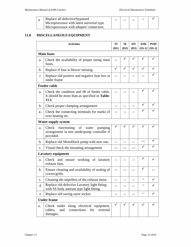
11.8 MISCELLANEOUS EQUIPMENT
Activities TI
(D1)
M
(D2)
HY
(D3)
IOH
(SS-1)
POH
(SS-2)
Main fuses
a. Check the availability of proper rating main fuses.
--
b. Replace if fuse is blown/ missing.
c Replace old positive and negative fuse box at under frame
-- -- -- --
Feeder cable
a. Check the condition and IR of feeder cable. It should be more than as specified in Table- 11.1.
-- -- --
b. Check proper clamping arrangement -- -- --
c. Check the connecting terminals for marks of over heating etc.
-- -- --
Water supply system
a. Check functioning of water pumping arrangement in test mode/pump controller if provided.
b. Replace old Monoblock pump with new one. -- -- -- ---
c. Visual check the mounting arrangement --- --- ---
Lavatory equipment
a. Check and ensure working of lavatory exhaust fans.
-- -- --
b. Ensure cleaning and availability of sealing of covers/grills.
-- -- -- --
c. Cleaning the impellers of the exhaust items -- -- -- --
d Replace old defective Lavatory light fitting with SS body antirust type light fitting.
-- -- -- --
e Replace old saving razor socket. -- -- -- --
Under frame
a. Check under slung electrical equipment, cables, and connections for external damages.
Maintenance Manual of LHB Coaches Electrical Maintenance Schedules
Chapter 11 Page 14 of 65
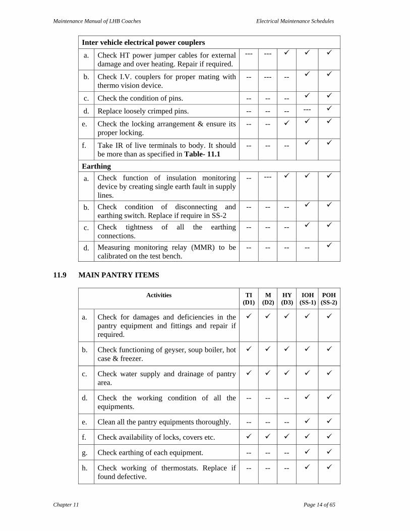
Inter vehicle electrical power couplers
a. Check HT power jumper cables for external damage and over heating. Repair if required.
--- ---
b. Check I.V. couplers for proper mating with thermo vision device.
-- --- --
c. Check the condition of pins. -- -- --
d. Replace loosely crimped pins. -- -- -- ---
e. Check the locking arrangement & ensure its proper locking.
-- --
f. Take IR of live terminals to body. It should be more than as specified in Table- 11.1
-- -- --
Earthing
a. Check function of insulation monitoring device by creating single earth fault in supply lines.
-- ---
b. Check condition of disconnecting and earthing switch. Replace if require in SS-2
-- -- --
c. Check tightness of all the earthing connections.
-- -- --
d. Measuring monitoring relay (MMR) to be calibrated on the test bench.
-- -- -- --
11.9 MAIN PANTRY ITEMS
Activities TI (D1)
M (D2)
HY (D3)
IOH (SS-1)
POH (SS-2)
a. Check for damages and deficiencies in the pantry equipment and fittings and repair if required.
b. Check functioning of geyser, soup boiler, hot case & freezer.
c. Check water supply and drainage of pantry area.
d. Check the working condition of all the equipments.
-- -- --
e. Clean all the pantry equipments thoroughly. -- -- --
f. Check availability of locks, covers etc.
g. Check earthing of each equipment. -- -- --
h. Check working of thermostats. Replace if found defective.
-- -- --

Maintenance Manual of LHB Coaches Electrical Maintenance Schedules
Chapter 11 Page 15 of 65
Activities TI (D1)
M (D2)
HY (D3)
IOH (SS-1)
POH (SS-2)
i. Check working of electric chimney -- -- --
j. replace the filter of electric chimney. -- --
j. Check the working of boilers. -- --
k. Clean the boilers for removing scaling etc. -- --
l. Check the heating element of boilers and replace if required.
-- -- --
m. Check the working of indication lamps. -- -- --
n. Check for any leakage. -- -- --
o. Check the working of deep freezer, bottle cooler, hot case and OTG.
-- -- --
p. Check working/cooling of refrigerator. Measure the current of compressor of refrigerator.
-- -- --
q. Check starting capacitor value with LCR meter. If value is low, replace it.
-- -- --
r. Check the working of starting relay for compressors.
-- -- --
s. Clean the condenser of refrigerator and deep freezer.
-- -- --
t. Check the insulation resistance of live terminals to body. It should be more than as specified in Table- 11.1.
-- -- --
u. Exhaust fans -- -- --
v Replace all 3 pin sockets with 2 pole MCBs of proper rating.
-- -- -- --
w Replace dented/pitted doors of Deep freezer. -- -- -- --
x Replace all old hot water boiler /geysers with new one.
-- -- -- --
y Replace complete Heater assembly with new one.
-- -- -- --
z Replace dented/pitted doors of Hot cases. -- -- -- --

Maintenance Manual of LHB Coaches Electrical Maintenance Schedules
Chapter 11 Page 16 of 65
11.10 MINI PANTRY ITEMS (DEEP FREEZER, BOTTLE COOLER, HOT CASE)
Activities TI
(D1)
M
(D2)
HY
(D3)
IOH
(SS-1)
POH
(SS-2)
a. Check working of all mini-pantry equipment. -- -- --
b. Clean all the pantry equipments thoroughly. -- -- --
c. Check and record current drawn by compressors for bottle cooler & deep freezer.
-- -- --
d. Clean the condenser of refrigerator and deep freezer.
-- -- --
e. Check starting capacitor value with LCR meter. If value is low, replace it.
-- -- --
f. Check the working of starting relay for compressors.
-- -- --
g. Check the working of boilers. -- -- --
h. Clean the boilers for removing scaling etc -- -- --
i. Check working of thermostats of boilers. -- -- --
j. Check the heating element of boilers and replace if required.
-- -- --
k. Check for any leakage. -- -- --
l. Check the working of hot case and its thermostats.
-- -- --
m. Check the working of indication lamps. -- -- --
n. Check the insulation resistance of live terminals to body. It should be more than as specified in Table- 11.1.
-- -- --
o. Check earthling of each equipment. -- -- --
p. Replenish the item if found deficient. -- -- --
q Replace dented/pitted doors of Deep freezer. -- -- -- --
r Replace all old hot water boiler /geysers with new one.
-- -- -- --
s Replace complete Heater assembly with new one.
-- -- -- --
t Replace dented/pitted doors of Hot cases. -- -- -- --

Maintenance Manual of LHB Coaches Electrical Maintenance Schedules
Chapter 11 Page 17 of 65
Table- 11.1
Sr. No. Circuit Voltage Capacity of Megger used Min. value of IR required
1. 750V 1000V 05 M ohms
2. 415V 500V 03 M ohms
3. 230V 500V 02 M ohms
4. 190V 500V 02 M ohms
5. 110V 500V 02 M ohms
6. 24V 100V 01 M ohms
11.11 WORK INSTRUCTIONS FOR SHOP SCHEDULE SS-1
11.11.1 Pre-Inspection
Place the coach on the pit line and inspect the electrical and air conditioning equipments.
Conduct the pre-cooling test as per Annexure ‘11.2’.
If the cooling time is less than the specified values, regular maintenance/ overhauling of air conditioning equipments is to be carried out.
If cooling time is more than the specified values, complete air-conditioning system including supply air duct, coach sealing etc. needs to be checked.
Down load the failure data of RMPU from Microprocessor controller for analysis and attention.
Check operation of all the lights, pantry equipments, exhausts fans, WRA, battery charger, protections etc. and note down the defects and deficiencies.
11.11.2 Dusting
Remove dust of the conditioned supply air duct with the help of compressed air/ vacuum cleaner.
11.11.3 Final Testing
After installation of all the electrical equipments on the coach all the electrical equipments shall be checked and tested as per Annexure 11.1.
The following procedure shall be followed for different tests on air-conditioning
system:
1. Air Delivery Test
Conduct air delivery test after checking air leakage in the complete air-conditioning system.
Calculate the total air delivery for any coach from the fundamental requirement of the ‘FRESH AIR REQUIRED PER PERSON’ depending upon the type of coach.
Minimum fresh air required for per person for AC coach is 0.35 m³/ min.

Maintenance Manual of LHB Coaches Electrical Maintenance Schedules
Chapter 11 Page 18 of 65
Measure fresh, return and exhaust air velocities with the help of anemometer using suitable hoods to avoid turbulence of air.
Compute the volume of air by multiplying the velocity with face area.
For ideal condition, the exhaust air should be equal to fresh air or it can be less by 10% but no reasons it should not be more than fresh air.
2. Pre-cooling Test
This test shall be conducted to record the time taken for cooling the coach without passenger, with fresh air filters closed, lights switched ‘ON’ and after raising the inside temperature of air-conditioned compartment to 45°C.
Procedure: 1. Place the coach inside the shed. 2. Close all fresh air intake openings. 3. Record dry and wet bulbs temperature of ambient air. 4. A sample calculation for finding out compensating heat load for AC chair car
is given at Annexure 11.4. 5. Calculate the electrical compensating heat load from the graph chart as per
sample calculation given in Annexure 11.4 6. Provide the electrical compensating load, as calculated above, inside the coach.
This load should be kept in OFF condition till further instruction. 7. Raise the inside temperature of the coach to 45°C by switching ‘ON’ heater
circuit in test mode. 8. Switch ‘ON’ all lights. Set the temperature setting at position no. 6th (i.e.
24.04°C) of both sides and run both the AC package units in auto mode keeping compensating load ‘OFF’.
9. Record the timings for ‘cut off’ of both the plants and other parameters during the test as per Annexure 11.2.
10. Total time taken by each plant to cool the coach should not exceed one hour. 11. Feeder testing on 750 volt. 12. Testing of local mains supply system. 13. Measurement of currents for AC plant.
11.11.4 Final Joint Inspection
Workshop supervisor with divisional supervisor shall jointly inspect the coach and the performance of electrical and refrigeration equipments shall be recorded as per Proforma at Annexure 11.6.
A details of equipments changed with new assemblies will also be handed over along with the coach to the divisional representative. Any attention, if required to the equipments shall be given before dispatch of the coach from workshop to division.
Maintenance Manual of LHB Coaches Electrical Maintenance Schedules
Chapter 11 Page 19 of 65
11.12 WORK INSTRUCTIONS FOR SHOP SCHEDULE SS-2
11.12.1 Pre-Inspection Carry out activities as given under SS-I.
11.12.2 Dusting Remove the dust from conditioned supply air duct by compressed air / vacuum
cleaner.
11.12.3 Striping Remove the following air conditioning and electrical equipments for overhauling:
Roof Mounted AC package units Water raising apparatus. Battery and battery Charger. Light fittings. Exhaust fans Pantry equipments. Before overhauling, measure the insulation resistance of all the electrical equipments to know the condition of equipments.
11.12.4 Equipping
1. Fit all the refrigeration and electrical equipments to its respective locations.
2. Connect all the electrical wirings, air supply ducts in the air-conditioning unit (RMPU) and other electrical systems wherever required.
11.12.5 Final Testing
After installation of all the electrical equipments on the coach shall be checked and tested as per Annexure 11.3.
The following procedures shall be followed for different tests on air conditioning system.
1 Air delivery test
Carry out test as given under SS-I.
2 Pre-cooling test
Carry out test as given under SS-I. 3 Pull down test
Pull down test is conducted to see that AC plant is capable of cooling the coach in extreme summer condition when the coach is fully occupied.
Procedure:
1. Adjust all fresh air openings as per the requirement of the coach.
2. Switch ‘ON’ the electrical compensating load.
3. Raise the compartment temperature to 45 º C by switching ‘ON’ heater circuit in test mode.
4. Set the thermostat setting on both AC control panel at position 6 (i.e. 24.04°C). Switch ‘ON’ all lights and fans.
5. Run both AC package units as soon as compartment temperature is raised to 45 ºC and record the time.
Maintenance Manual of LHB Coaches Electrical Maintenance Schedules
Chapter 11 Page 20 of 65
6. Record timings of ‘cut off’ of each AC plant. It should not exceed 2 hours.
7. Electrical compensating heat load may be reduced (if testing persons are required to be present inside the coach) 120 W per person inside the conditioned space. (Proforma for recording pull down test is given in Annexure 11.5).
11.12.6 Final Joint Inspection
As given under SS-I.
Maintenance of Generator cum Brake Van
For the maintenance of diesel generator set and its equipment follow the
maintenance instructions of OEM.
*******
Maintenance Manual of LHB Coaches Electrical Maintenance Schedules
Chapter 11 Page 21 of 65
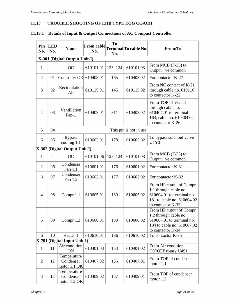
11.13 TROUBLE SHOOTING OF LHB TYPE EOG COACH 11.13.1 Details of Input & Output Connections of AC Compact Controller
Pin No.
LED No.
Name From cable
No.
To Terminal
No. To cable No. From/To
X-301 (Digital Output Unit-I)
1 - OC 610101.01 125, 124 610101.03 From MCB (F-35) to Output +ve common
2 01 Controller OK 610408.01 165 610408.02 For contactor K-27
3 02 Recirculation
Air 610115.01 145 610115.02
From NC contact of K-21 through cable no. 610116 to contactor K-22
4 03 Ventillation
Fan-1 610403.01 311 610403.02
From TOP of Vent-1 through cable no. 610404.01 to terminal 164, cable no. 610404.02 to contactor K-26
5 04 This pin is not in use
6 05 Bypass
cooling 1.1 610603.01 178 610603.02
To bypass solenoid valve U1Y3
X-302 (Digital Output Unit-I)
1 - OC 610101.06 125, 124 610101.03 From MCB (F-35) to Output +ve common
2 06 Condenser
Fan 1.1 610601.01 176 610601.02 For contactor K-31
3 07 Condenser
Fan 1.2 610602.01 177 610602.02 For contactor K-32
4 08 Compr 1.1 610605.01 180 610605.02
From HP cutout of Compr 1.1 through cable no. 610604.01 to terminal no. 181 to cable no. 610604.02 to contactor K-33
5 09 Compr 1.2 610608.01 183 610608.02
From HP cutout of Compr 1.2 through cable no. 610607.01 to terminal no. 184 to cable no. 610607.02 to contactor K-34
6 10 Heater 1 610610.01 186 610610.02 To contactor K-35 X-701 (Digital Input Unit-I)
1 11 Air condition
ON 610401.03 153 610401.02
From Air condition ON/OFF rotary U4S1
2 12 Temperature Condenser
motor 1.1 OK 610407.02 156 610407.01
From TOP of condenser motor 1.1
3 13 Temperature Condenser
motor 1.2 OK 610409.02 157 610409.01
From TOP of condenser motor 1.2

Maintenance Manual of LHB Coaches Electrical Maintenance Schedules
Chapter 11 Page 22 of 65
Pin No.
LED No.
Name From cable
No.
To Terminal
No. To cable No. From/To
4 14 Vent motor-1 610405.02 154 610405.01 From NC contact of contactor K-26
5 15 Temperature Heater-1 OK
610410.02 158 610410.01 From OHP, Heater-1
6 - IC 610102.05 127, 126 610102.03 From MCB (F-35) to Input -ve common
7 16 Low Pressure
1.1 OK 610412.02 159 610412.01 From LP cutout 1.1
8 17 Low Pressure
1.2 OK 610414.02 160 610414.01 From LP cutout 1.2
9 18 Control
Pressure 1 610415.02 161 610415.01
From Control Pressure Cutout Condenser 1.1 or Control Pressure Cutout Condenser 1.2
10 19 HP 1.1 Fault 610606.01 182 610606.02 From HP Cutout Comp 1.111 110 HP 1.2 Fault 610609.01 185 610609.02 From HP Cutout Comp 1.2
12 - IC 610102.04 127, 126 610102.03 From MCB (F-35) to Input -ve common
X-501 (Digital Output Unit-2)
6 - OC 610101.07 125, 124 610101.03 From MCB (F-35) to Output +ve common
5 011 Fault 610125.01 148 610125.02 For Fault Lamp U4H1
4 012 Fresh Air 610110.01 144 610110.02 From NC contact of K-22 through cable no. 610111 to contactor K-21
3 013 Ventillation
Fan-2 610411.01 312 610411.02
From TOP of Vent-2 through cable no. 610413.01 to terminal 167, cable no. 610413.02 to contactor K-28
2 014 Exhaust Fan 610416.01 313 610416.02 For contactor K-29
1 015 Bypass
cooling 1.2 610703.01 179 610703.02
For bypass solenoid valve U2Y3
X-502 (Digital Output Unit-2)
6 - OC 610101.04 125, 124 610101.03 From MCB (F-35) to Output +ve common
5 016 Condenser
Fan 2.1 610701.01 187 610701.02 For contactor K-36
4 017 Condenser
Fan 2.2 610702.01 188 610702.02 For contactor K-37
3 018 Compr 2.1 610705.01 191 610705.02
From HP cutout of Compr 2.1 through cable no. 610704.01 to terminal no. 192 to cable no. 610704.02 to contactor K-38

Maintenance Manual of LHB Coaches Electrical Maintenance Schedules
Chapter 11 Page 23 of 65
Pin No.
LED No.
Name From cable
No.
To Terminal
No. To cable No. From/To
2 019 Compr 2.2 610708.01 194 610708.02
From HP cutout of Compr 2.2 through cable no. 610707.01 to terminal no. 196 to cable no. 610707.02 to contactor K-39
1 020 Heater 2 610710.01 197 610710.02 For contactor K-40 X-702 (Digital Input Unit-2)
11 111 400V OK 610124.02 140 610124.01 From NO contact of contactor K-23
10 112 Temperature
condenser motor 2.1 OK
610501.02 170 610501.01 From TOP of condenser motor 2.1
9 113 Temperature
condenser motor 2.2 OK
610502.02 171 610502.01 From TOP of condenser motor 2.2
8 114 Vent motor-2
Fault 610406.02 155 610406.01 From NC contact of K-28
7 115 Temperature Heater-2 OK
610503.02 172 610503.01 From OHP of Heater-2
6 - IC 610102.06 127, 126 610102.03 From MCB (F-35) to Input -ve common
5 116 Low pressure
2.1 OK 610504.02 173 610504.01 From LP cutout 2.1
4 117 Low Pressure
2.2 OK 610505.02 174 610505.01 From LP cutout 2.2
3 118 Control
Pressure 2 610506.02 175 610506.01
From control pressure cut out Condenser 2.1 or Condenser 2.2
2 119 High Pressure
2.1 Fault 610706.01 193 610706.02 From HP cutout compr 2.1
1 120 High Pressure
2.2 Fault 610706.01 195 610709.02 From HP cutout compr 2.2
11.13.2 Air Conditioning Unit not Working
In case of non working of following equipment of AC unit, check 415V AC, three phase supply at the Contactors, MCBs & terminals of the respective equipment.
Equipment MCB No. Contactor No. Terminal No.
Ventilation fan-1 1 K-26 231, 232, 233
Ventilation fan-2 2 K-28 235, 236, 237
Condenser Motor CD-1.1 6 K-31 253, 254, 255
Condenser Motor CD-1.2 7 K-32 256, 257, 258
Compressor 1.1 3 K-33 239, 240, 241
Compressor 1.2 5 K-34 243, 244, 245

Maintenance Manual of LHB Coaches Electrical Maintenance Schedules
Chapter 11 Page 24 of 65
Equipment MCB No. Contactor No. Terminal No.
Heater (HTR)-1 8 K-35 247, 248, 249
Condenser Motor CD-2.1 12 K-36 273, 274, 275
Condenser Motor CD-2.2 13 K-37 276, 277, 278
Compressor 2.1 9 K-38 259, 260, 261
Compressor 2.2 11 K-39 263, 264, 265
Heater (HTR)-2 14 K-40 267, 268, 269
Check following after switching ON AC control MCB S1F35
1 Ensure glowing of 400V OK (11) AC ON indication at CPU. If indication is glowing, then check 415V AC in the panel. If 415V AC is proper in the panel but the indication of 415V AC is not glowing in the CPU, then check relay S1K23. Replace if defective or bypass the contacts 33-34. Check fuse S1F73 before bypass. Replace the fuse if defective.
2 If the indication of Controller OK is not glowing in the CPU, then check relay S1K27. Replace if defective or bypass the contacts.
3 A Heater not working
i) Ensure proper working of Heater MCB & ON Heater Contactor K-35 & K-40.
ii) Keep temperature selection rotary at Maximum.
B If Heater Contactor is ON then note the following display at CPU:
i) LED 5 & 15 (Temperature of Heater OK) are glowing. If these are not glowing, it means heater is tripped from OHP. Ensure proper rotation & working of blower motor.
ii) Clean fresh air & return air filters.
C Loose duct air sensor connection
Check terminal block at the left side of control panel for terminal no. 136 & 137 for Unit-1 and terminal no. 138 & 139 for Unit-2. Tighten if loose.
D If the Heater contactor is ON & coach is not heating. Check current at the heater contactor. If current is not indicating at the contactor, it means heater is trip from EHTI. Switch OFF the MCB as the glass cartridge must have blown and it needs to be replaced.
E If both side heater units have trip from EHTI. Heating mode can not be operated. Switch OFF both MCBs and face the situation with common prudence.
4 If Ventilation fan, Condenser motor or compressor is trip from TOP, check for single phasing in the circuit between motor & MCB.
Maintenance Manual of LHB Coaches Electrical Maintenance Schedules
Chapter 11 Page 25 of 65
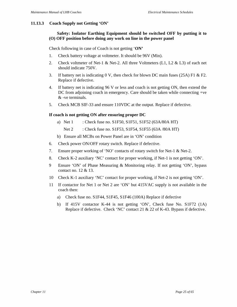
11.13.3 Coach Supply not Getting ‘ON’
Safety: Isolator Earthing Equipment should be switched OFF by putting it to (O) OFF position before doing any work on line in the power panel
Check following in case of Coach is not getting ‘ON’
1. Check battery voltage at voltmeter. It should be 96V (Min).
2. Check voltmeter of Net-1 & Net-2. All three Voltmeters (L1, L2 & L3) of each net should indicate 750V.
3. If battery net is indicating 0 V, then check for blown DC main fuses (25A) F1 & F2. Replace if defective.
4. If battery net is indicating 96 V or less and coach is not getting ON, then extend the DC from adjoining coach in emergency. Care should be taken while connecting +ve & -ve terminals.
5. Check MCB SIF-33 and ensure 110VDC at the output. Replace if defective.
If coach is not getting ON after ensuring proper DC
a) Net 1 : Check fuse no. S1F50, S1F51, S1F52 (63A/80A HT)
Net 2 : Check fuse no. S1F53, S1F54, S1F55 (63A /80A HT)
b) Ensure all MCBs on Power Panel are in ‘ON’ condition
6. Check power ON/OFF rotary switch. Replace if defective.
7. Ensure proper working of ‘NO’ contacts of rotary switch for Net-1 & Net-2.
8. Check K-2 auxiliary ‘NC’ contact for proper working, if Net-1 is not getting ‘ON’.
9 Ensure ‘ON’ of Phase Measuring & Monitoring relay. If not getting ‘ON’, bypass contact no. 12 & 13.
10 Check K-1 auxiliary ‘NC’ contact for proper working, if Net-2 is not getting ‘ON’.
11 If contactor for Net 1 or Net 2 are ‘ON’ but 415VAC supply is not available in the coach then:
a) Check fuse no. S1F44, S1F45, S1F46 (100A) Replace if defective
b) If 415V contactor K-44 is not getting ‘ON’, Check fuse No. S1F72 (1A) Replace if defective. Check ‘NC’ contact 21 & 22 of K-43. Bypass if defective.

Maintenance Manual of LHB Coaches Electrical Maintenance Schedules
Chapter 11 Page 26 of 65
11.13.4 Non-functioning of Battery Charger
If battery charger is not working then check Input (32A) & Output (63A) fuses of battery charger. Ensure proper tightened connections of three leads at connector (If battery charger is defective extend 110V DC supply from adjoining coach).
Procedure for extending 110V DC from adjoining coach
1 The lead (cable) for paralleling (extending feed) the DC supply should be clearly marked for +ve & -ve. The cross section of cable should not be less then 6 mm2 and the insulation should be proper. Damaged/jointed cable should not be used.
2 First connect the cable at the input side of S1F-33 MCB at defective coach. Due care should be taken for connecting +ve & -ve terminals.
3 Other end of the lead should be connected at the output side of S1F-33 MCB at Healthy coach. Due care should be taken for connecting +ve & -ve terminals.
4 DC will be available at defective coach and the coach can be switched ON.
11.13.5 Defect in Lighting System (Lights not getting ON)
1 Ensure input & output supply of Lighting Transformer.
2 If input supply of lighting transformer is missing then check fuse no. S1F74 & S1F75. Replace if defective.
3 Check 110V AC at output of MCB S1F39 & SIF 40.
4 Check MCB S1F30 for Lighting Control. Replace if defective (MVR).
5 If Lighting Contactors K-11 & K-14 are not ON, then ensure proper working of Power ON/OFF rotary switch and Push ON & Push OFF switches of Lighting.
6 If lights are not ON then bypass contact no. 15 & 18 of S1K17. If then also lights are not getting ON then bypass Lighting contactors S1K11 & S1K14.
Contactor for Night Light S1K13
Contactor for Reading Light S1K12
Contactor for Emergency Light S1K15 & S1K16
Contactor for AC Light S1K11 & S1K14

Maintenance Manual of LHB Coaches Electrical Maintenance Schedules
Chapter 11 Page 27 of 65
11.13.6 Frequent Tripping of Supply in Coach
1 Phase Monitoring Relay is not working properly
2 If Red LED indication at Phase Monitoring Relay Trip is glowing, bypass the contact 12 & 13.
3 Emergency Lights should work automatically during tripping of power supply in coach, if it is not working push Light ON switch & if the lights donot gets ON then check MCB no. 24, 25 & 26. Switch these MCB ON, if lights not work after this, then wedge the contactor K-12.
11.13.7 If AC Control MCB (F-35) Trips
1 Checking of –ve & +ve wire Earth Fault
i) Disconnect negative wire from AC control MCB (F-35) and ON the MCB, if the MCB trips, it indicates that there is +ve earth fault otherwise not.
ii) Disconnect positive wire from AC control MCB (F-35) and ON the MCB, if the MCB trips, it indicates that there is -ve earth fault otherwise not.
2 Positive wire Earth Fault
Disconnect negative wire from AC control MCB (F-35) and ON the MCB, if the MCB trips then disconnect cable no. 610101.08 from terminal no. 125 and switch ON the MCB, if it do not holds, then check for short circuit & earth fault in Microprocessor & in the coils and diodes fitted in the contactors of AC circuit.
Disconnect cable no. 610101.82 from terminal no. 125 and switch ON the MCB. If it holds then reconnect this cable at terminal 125 and disconnect cable 610101.12 from terminal 162 and if the MCB holds in this condition then bypass the CPU and run all motors and compressors through bypass.
Note: Heater should not be run in bypass condition. If it is done in emergency the coach should be under regular observation.
3 Negative wire Earth Fault
Disconnect positive wire from AC control MCB (F-35) and ON the MCB, if the MCB trips then disconnect cable no. 610102.07 from terminal no. 127 and switch ON the MCB, if it do not holds, then check for short circuit & earth fault in Microprocessor & in the coils and diodes fitted in the contactors of AC circuit.
If MCB holds after disconnecting cable no. 610102.07 from terminal no. 127, then reconnect it and disconnect cable no. 610102.18 from coil (A-2) of contactor for CD 1.2 (K-32). If then also the MCB trips then check the coils & diodes of contactor K-31, K-29, K-28, K-27, K-26 and replace the defective.
If the MCB holds after disconnecting cable no. 610102.18 from coil (A-2) of contactor for CD 1.2 (K-32), then reconnect the cable and disconnect cable no. 610102.19 from terminal 179 and if the MCB holds then switch OFF Unit-1.
If the MCB still trips after disconnecting cable no. 610102.19 from terminal 179 then reconnect it and disconnect cable no. 610102.26 from terminal 190 and if the MCB holds then switch OFF the Unit-2.
Extending 3 phase, 415VAC supply from adjoining coach

Maintenance Manual of LHB Coaches Electrical Maintenance Schedules
Chapter 11 Page 28 of 65
1 Switch OFF the Isolator Earthing Device of the defective coach by putting it to ‘O’ position.
2 Connect one end of the 3½ core paralleling lead at the output terminals of Contactor K-44 of the defective coach. The connections should be made with care i.e R, Y, B & Neutral.
3 Switch OFF the Isolator Earthing Device of the Healthy coach by putting it to ‘O’ position.
4 Connect one end of the 3½ core paralleling lead at the output terminals of Contactor K-44 of the healthy coach. The connections should be made with care i.e R, Y, B & Neutral.
5 Switch ON the Isolator Earthing Device of the Healthy coach. Don’t switch ON the Isolator Earthing Device of the defective coach.
6 Check the rotation of motors after switching ON supply in defective coach. Change the phase if rotation is not proper.
Keep the defective coach under observation
11.13.8 No Water in Coach
1 Empty water tank.
2 Check water pump contactor K-24 & K-25. One contactor should be in ON position.
3 Check Pump overload Relay F-21 & F-22 for trip. Black push should be in push condition for normal working.
4 If both pump contactors are OFF, check pump controller terminal 1 & 2. Ensure 24 V DC between terminal 1 & 2. If 24 VDC is not coming check pump control MCB F-20 for ON condition.
5 If 24 VDC is available at pump controller and the controller is not working bypass the controller by disconnecting cable no 32050504 from terminal no. 1 and connect it with cable no. 3308254 at terminal no 2 for operating pump-1 or at cable no. 3308253 at terminal no. 3 for operating pump-2.
6 If pump is working but water is not coming, remove air lock of the system or check for proper rotation of the pump.

Maintenance Manual of LHB Coaches Electrical Maintenance Schedules
Chapter 11 Page 29 of 65
11.14 TROUBLE SHOOTING OF LHB TYPE GENERATOR CAR
11.14.1 Engine not Starting
Ensure 24VDC supply
Magnetic switch not operating Self starter not working. Check the solenoid coil.
Ensure supply at FSS or shut down valve.
Check Emergency OFF switch at engine panel. It may be stuck in pushed condition.
Check Emergency OFF switch near engine room door. It may be stuck in pushed condition. Reset it.
11.14.2 ACB not getting ON
Ensure proper position of Plant Selector Switch.
Switch ON S2 panel.
Check K-20 relay and ensure it is ON.
Check indication at UVR. Check 6A fuses 1, 2, 3 for Set-A & 12, 13, 14 for Set-B and ensure 415 VAC at these fuses. If these are OK and supply is available but the indication is still coming at UVR, disconnect cable no.1 AFR from NC point of UVR.
11.14.3 Feeder Contactor not getting ON
Check fuse no. 9 (Set-A) and fuse no. 18 (Set-B). Replace if blown.
Check Relay K-12 for Set-A & K-13 for Set-B. These should be ON.
Check coil of feeder contactor.
11.14.4 Bus Coupler not getting ON
Ensure proper position of Plant Selector Switch.
Check fuse no. 8 (Set-A) and fuse no. 17 (Set-B). Replace if blown.
Check Relay K-11 for Set-A & K-10 for Set-B. These should be ON.
Check coil of Bus Coupler contactor.
11.14.5 Safety Loop not getting ON
Check fuse no. 19 (Set-A) and fuse no. 20 (Set-B). Replace if blown.
Check Relay K-15 & K-18. These should be ON.
Check safety switches fitted with I.V.Coupler. Ensure proper working or bypass them.
Check FEL & FOL1. Reset if indication is coming.
If FEL indication is coming frequently. Check the rake for earth leakage.
11.14.6 Main Battery Charger not getting ON
Check 100A fuses (44, 45, 46) & ensure supply at them.
Check male sockets of battery charger for looseness. Ensure they are tight.
Check battery charger incoming fuse.
11.14.7 Main Battery Charger ON but battery not charging
Check fuse no. 1 (63A) +ve & -ve box in underframe.
Check battery cell couplings and tighten if found loose.
Check all cells and replace the defective battery set.

Maintenance Manual of LHB Coaches Electrical Maintenance Schedules
Chapter 11 Page 30 of 65
11.14.8 Emergency Battery Charger not switching ON in case of Main Battery Charger defective
Check relay 24VDC inside charger. Wedge if not ON.
11.14.9 110V AC Lights not getting ON
Check 10A fuses no. 74 & 75 in the incoming supply of lighting transformer
Lighting transformer is of the rating 230/110V. Check incoming and output supply accordingly.
Check K-48 interlocking relay. It should be ON.
Check K-11 & K-14 relays. These should be ON.
11.14.10 Emergency Lights not getting ON
Ensure 110VDC supply at voltmeter
Check K-08 relay which is controlled by MVR. It should be ON.
Check K-16 relay which is for Emergency Lights. It should be ON.
11.14.11 Transformer contactor not getting ON
A) For LHB Generator Car
Ensure 110VDC at the voltmeter of S1 panel.
ON the power supply MCB and check is it passing the supply
Check DC/DC converter fitted on the contactor. Replace if defective.
Check 1A fuses in PMR circuit (fuse no. 90, 91, 92 for Set-A and 94, 95, 96 for Set-B)
Check Isolator Earthing Device. It should be ON.
Switch On the Public Address System MCB.
B) For RCF built Generator Car
Check DC/DC converter fitted on the contactor. Replace if defective.
Check Push button. Replace if defective.
Ensure availability of 110VDC supply.
Switch ON the Power Supply MCB
11.14.12 415V Main contactor (K-44) not getting ON
Check 2A fuse no. 72
Check AC/DC converter
Ensure neutral at AC/DC converter.
*******
Maintenance Manual of LHB Coaches Electrical Maintenance Schedules
Chapter 11 Page 31 of 65
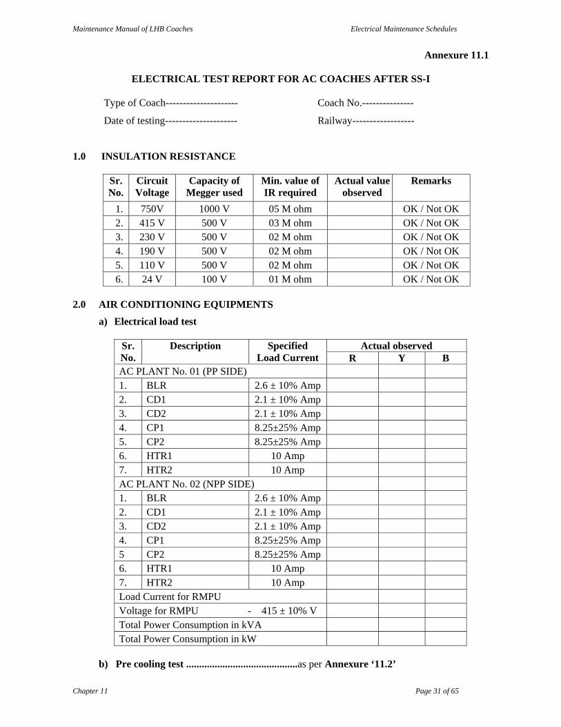
Annexure 11.1
ELECTRICAL TEST REPORT FOR AC COACHES AFTER SS-I
Type of Coach--------------------- Coach No.---------------
Date of testing--------------------- Railway------------------
1.0 INSULATION RESISTANCE
Sr. No.
Circuit Voltage
Capacity of Megger used
Min. value of IR required
Actual value observed
Remarks
1. 750V 1000 V 05 M ohm OK / Not OK 2. 415 V 500 V 03 M ohm OK / Not OK 3. 230 V 500 V 02 M ohm OK / Not OK 4. 190 V 500 V 02 M ohm OK / Not OK 5. 110 V 500 V 02 M ohm OK / Not OK 6. 24 V 100 V 01 M ohm OK / Not OK
2.0 AIR CONDITIONING EQUIPMENTS
a) Electrical load test
Sr. No.
Description Specified Load Current
Actual observed R Y B
AC PLANT No. 01 (PP SIDE) 1. BLR 2.6 ± 10% Amp 2. CD1 2.1 ± 10% Amp 3. CD2 2.1 ± 10% Amp 4. CP1 8.25±25% Amp 5. CP2 8.25±25% Amp 6. HTR1 10 Amp 7. HTR2 10 Amp AC PLANT No. 02 (NPP SIDE) 1. BLR 2.6 ± 10% Amp 2. CD1 2.1 ± 10% Amp 3. CD2 2.1 ± 10% Amp 4. CP1 8.25±25% Amp 5 CP2 8.25±25% Amp 6. HTR1 10 Amp 7. HTR2 10 Amp Load Current for RMPU Voltage for RMPU - 415 ± 10% V Total Power Consumption in kVA Total Power Consumption in kW
b) Pre cooling test ...........................................as per Annexure ‘11.2’
Maintenance Manual of LHB Coaches Electrical Maintenance Schedules
Chapter 11 Page 32 of 65
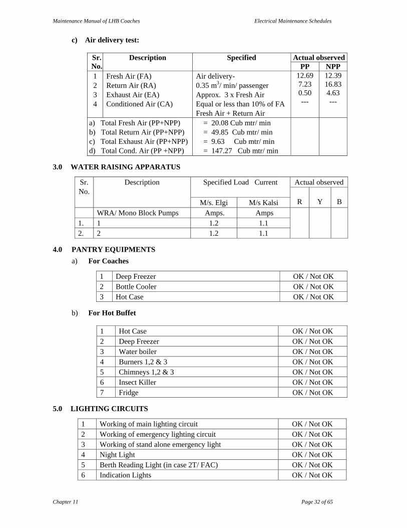
c) Air delivery test:
Sr. No.
Description Specified Actual observedPP NPP
1 2 3 4
Fresh Air (FA) Return Air (RA) Exhaust Air (EA) Conditioned Air (CA)
Air delivery- 0.35 m3/ min/ passenger Approx. 3 x Fresh Air Equal or less than 10% of FA Fresh Air + Return Air
12.69 7.23 0.50 ---
12.39 16.83 4.63 ---
a) Total Fresh Air (PP+NPP) b) Total Return Air (PP+NPP) c) Total Exhaust Air (PP+NPP) d) Total Cond. Air (PP +NPP)
= 20.08 Cub mtr/ min = 49.85 Cub mtr/ min = 9.63 Cub mtr/ min = 147.27 Cub mtr/ min
3.0 WATER RAISING APPARATUS
Sr. No.
Description Specified Load Current Actual observed
R
Y
B M/s. Elgi M/s Kalsi WRA/ Mono Block Pumps Amps. Amps 1. 1 1.2 1.1 2. 2 1.2 1.1
4.0 PANTRY EQUIPMENTS
a) For Coaches
1 Deep Freezer OK / Not OK 2 Bottle Cooler OK / Not OK 3 Hot Case OK / Not OK
b) For Hot Buffet
1 Hot Case OK / Not OK 2 Deep Freezer OK / Not OK 3 Water boiler OK / Not OK 4 Burners 1,2 & 3 OK / Not OK 5 Chimneys 1,2 & 3 OK / Not OK 6 Insect Killer OK / Not OK 7 Fridge OK / Not OK
5.0 LIGHTING CIRCUITS
1 Working of main lighting circuit OK / Not OK 2 Working of emergency lighting circuit OK / Not OK 3 Working of stand alone emergency light OK / Not OK 4 Night Light OK / Not OK 5 Berth Reading Light (in case 2T/ FAC) OK / Not OK 6 Indication Lights OK / Not OK

Maintenance Manual of LHB Coaches Electrical Maintenance Schedules
Chapter 11 Page 33 of 65
6.0 TESTING OF SWITCH BOARD CABINET
1 Battery Charger OK / Not OK 2 Emergency Battery Charger OK / Not OK 3 Exhaust Fans OK / Not OK 4
Insulating Monitoring Relay
750 V /415 V, 3 Ph OK / Not OK 110 V AC/ DC OK / Not OK
5 Controlled Discharge Toilet System OK / Not OK 7.0 EQUIPMENT SAFETY TESTS
SNo Equipments PP Side observations NPP Side observations 1. Blower Motor OK /Not OK OK /Not OK 2. Cond. Fan Motor 1 OK /Not OK OK /Not OK 3. Cond. Fan Motor 2 OK /Not OK OK /Not OK 4. OHP 1 OK /Not OK OK /Not OK 5. OHP 2 OK /Not OK OK /Not OK 6. Compressor-1 OK /Not OK OK /Not OK 7. Compressor-2 OK /Not OK OK /Not OK 8. LP-1 OK /Not OK OK /Not OK 9 LP-2 OK /Not OK OK /Not OK 10. HP-1 OK /Not OK OK /Not OK 11. HP-2 OK /Not OK OK /Not OK 12 CP-1 (By pass) OK /Not OK OK /Not OK 13 CP-2 (By pass) OK / Not OK OK / Not OK
8.0 PERFORMANCE OF EQUIPMENTS
SNo Equipments Performance 1. WRA 1 OK /Not OK 2. WRA 2 OK /Not OK 3. Flasher OK /Not OK 4. 750 V circuit OK /Not OK 5. Feeder 1 OK /Not OK 6. Feeder 2 OK /Not OK 7. Water Cooler OK /Not OK 8. Hot Case OK /Not OK 9. WSP OK /Not OK 10. Battery Charger OK /Not OK 11 Bottle cooler cum deep Freezer OK /Not OK 12. Hot Plate OK /Not OK 13 Refrigerator OK /Not OK 14. PAS ckt OK /Not OK
(Signature of testing In-charge)

Maintenance Manual of LHB Coaches Electrical Maintenance Schedules
Chapter 11 Page 34 of 65
Annexure 11.2
PROFORMA FOR RECORD OF PRE-COOLING TEST Conditions: 1. Type and coach No. ------------- 2. Supply Voltage -------------V 3. Ambient temperature -----------(DB) -------------WB Power panel side:
Rotary Switch
Position Coach
Temperature Deg.C at Cut - in
Cut-in Time
Coach TemperatureDeg.C at Cut -out
Cut-out Time
Time taken in min
Position 6 i.e. 24.04˚C
Non-Power panel side
Rotary Switch Position
Coach Temperature Deg.C at Cut - in
Cut-in Time
Coach Temperature
Deg.C at Cut - out
Cut-out Time
Time taken in min
Position 6 i.e. 24.04˚C
Total pre-cooling time:
PP side --------------min.
NPP side ------------min.
(Signature of testing In-charge)
Maintenance Manual of LHB Coaches Electrical Maintenance Schedules
Chapter 11 Page 35 of 65
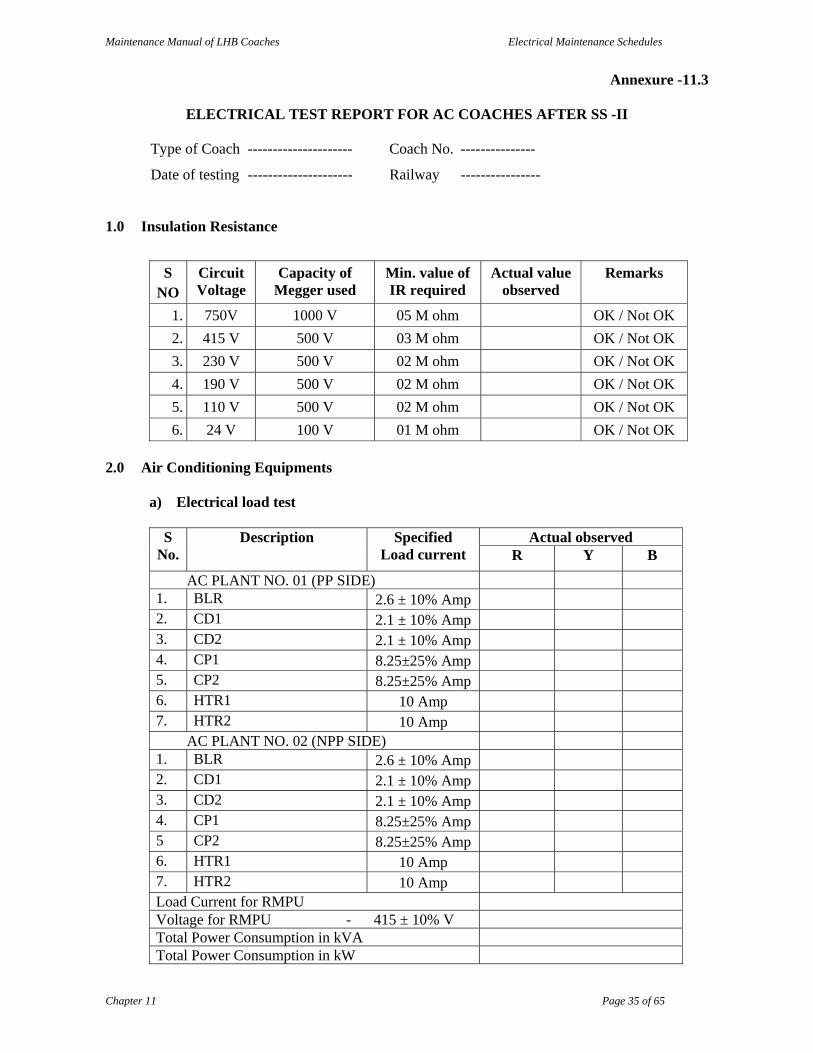
Annexure -11.3
ELECTRICAL TEST REPORT FOR AC COACHES AFTER SS -II
Type of Coach --------------------- Coach No. ---------------
Date of testing --------------------- Railway ----------------
1.0 Insulation Resistance
S
NO Circuit Voltage
Capacity of Megger used
Min. value of IR required
Actual value observed
Remarks
1. 750V 1000 V 05 M ohm OK / Not OK
2. 415 V 500 V 03 M ohm OK / Not OK
3. 230 V 500 V 02 M ohm OK / Not OK
4. 190 V 500 V 02 M ohm OK / Not OK
5. 110 V 500 V 02 M ohm OK / Not OK
6. 24 V 100 V 01 M ohm OK / Not OK
2.0 Air Conditioning Equipments a) Electrical load test
S
No. Description Specified
Load current Actual observed
R Y B
AC PLANT NO. 01 (PP SIDE) 1. BLR 2.6 ± 10% Amp 2. CD1 2.1 ± 10% Amp 3. CD2 2.1 ± 10% Amp 4. CP1 8.25±25% Amp 5. CP2 8.25±25% Amp 6. HTR1 10 Amp 7. HTR2 10 Amp
AC PLANT NO. 02 (NPP SIDE) 1. BLR 2.6 ± 10% Amp 2. CD1 2.1 ± 10% Amp 3. CD2 2.1 ± 10% Amp 4. CP1 8.25±25% Amp 5 CP2 8.25±25% Amp 6. HTR1 10 Amp 7. HTR2 10 Amp Load Current for RMPU Voltage for RMPU - 415 ± 10% V Total Power Consumption in kVA Total Power Consumption in kW
Maintenance Manual of LHB Coaches Electrical Maintenance Schedules
Chapter 11 Page 36 of 65
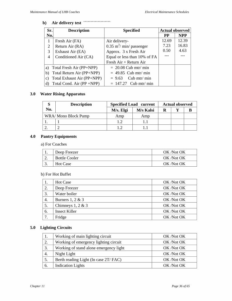
b) Air delivery test ```````````````````
Sr. No.
Description Specified Actual observedPP NPP
1 2 3 4
Fresh Air (FA) Return Air (RA) Exhaust Air (EA) Conditioned Air (CA)
Air delivery- 0.35 m3/ min/ passenger Approx. 3 x Fresh Air Equal or less than 10% of FAFresh Air + Return Air
12.69 7.23 0.50 ---
12.39 16.83 4.63 ---
a) Total Fresh Air (PP+NPP) b) Total Return Air (PP+NPP) c) Total Exhaust Air (PP+NPP) d) Total Cond. Air (PP +NPP)
= 20.08 Cub mtr/ min = 49.85 Cub mtr/ min = 9.63 Cub mtr/ min = 147.27 Cub mtr/ min
3.0 Water Rising Apparatus
S No.
Description Specified Load current Actual observed M/s. Elgi M/s Kalsi R Y B
WRA/ Mono Block Pump Amp Amp 1. 1 1.2 1.1 2. 2 1.2 1.1
4.0 Pantry Equipments
a) For Coaches
1. Deep Freezer OK /Not OK 2. Bottle Cooler OK /Not OK 3. Hot Case OK /Not OK
b) For Hot Buffet
1. Hot Case OK /Not OK 2. Deep Freezer OK /Not OK 3. Water boiler OK /Not OK 4. Burners 1, 2 & 3 OK /Not OK 5. Chimneys 1, 2 & 3 OK /Not OK 6. Insect Killer OK /Not OK 7. Fridge OK /Not OK
5.0 Lighting Circuits
1. Working of main lighting circuit OK /Not OK 2. Working of emergency lighting circuit OK /Not OK 3. Working of stand alone emergency light OK /Not OK 4. Night Light OK /Not OK 5. Berth reading Light (In case 2T/ FAC) OK /Not OK 6. Indication Lights OK /Not OK
Maintenance Manual of LHB Coaches Electrical Maintenance Schedules
Chapter 11 Page 37 of 65
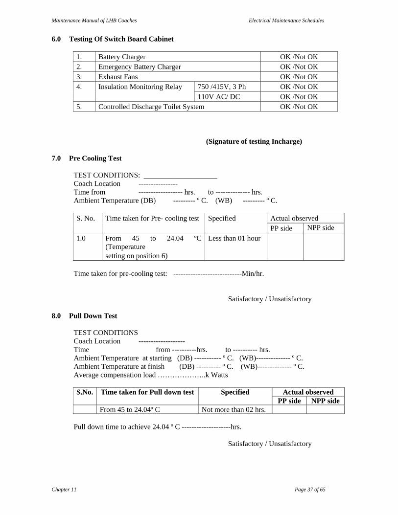
6.0 Testing Of Switch Board Cabinet
1. Battery Charger OK /Not OK 2. Emergency Battery Charger OK /Not OK 3. Exhaust Fans OK /Not OK 4.
Insulation Monitoring Relay 750 /415V, 3 Ph OK /Not OK 110V AC/ DC OK /Not OK
5. Controlled Discharge Toilet System OK /Not OK
(Signature of testing Incharge)
7.0 Pre Cooling Test TEST CONDITIONS: ____________________ Coach Location ---------------- Time from ------------------ hrs. to -------------- hrs. Ambient Temperature (DB) --------- º C. (WB) --------- º C. S. No. Time taken for Pre- cooling test Specified
Actual observed PP side NPP side
1.0 From 45 to 24.04 ºC (Temperature setting on position 6)
Less than 01 hour
Time taken for pre-cooling test: ----------------------------Min/hr.
Satisfactory / Unsatisfactory
8.0 Pull Down Test TEST CONDITIONS Coach Location ------------------- Time from ----------hrs. to ---------- hrs. Ambient Temperature at starting (DB) ----------- º C. (WB)-------------- º C. Ambient Temperature at finish (DB) ---------- º C. (WB)-------------- º C. Average compensation load ………………..k Watts S.No. Time taken for Pull down test Specified
Actual observed
PP side NPP side From 45 to 24.04º C Not more than 02 hrs.
Pull down time to achieve 24.04 º C --------------------hrs.
Satisfactory / Unsatisfactory
Maintenance Manual of LHB Coaches Electrical Maintenance Schedules
Chapter 11 Page 38 of 65
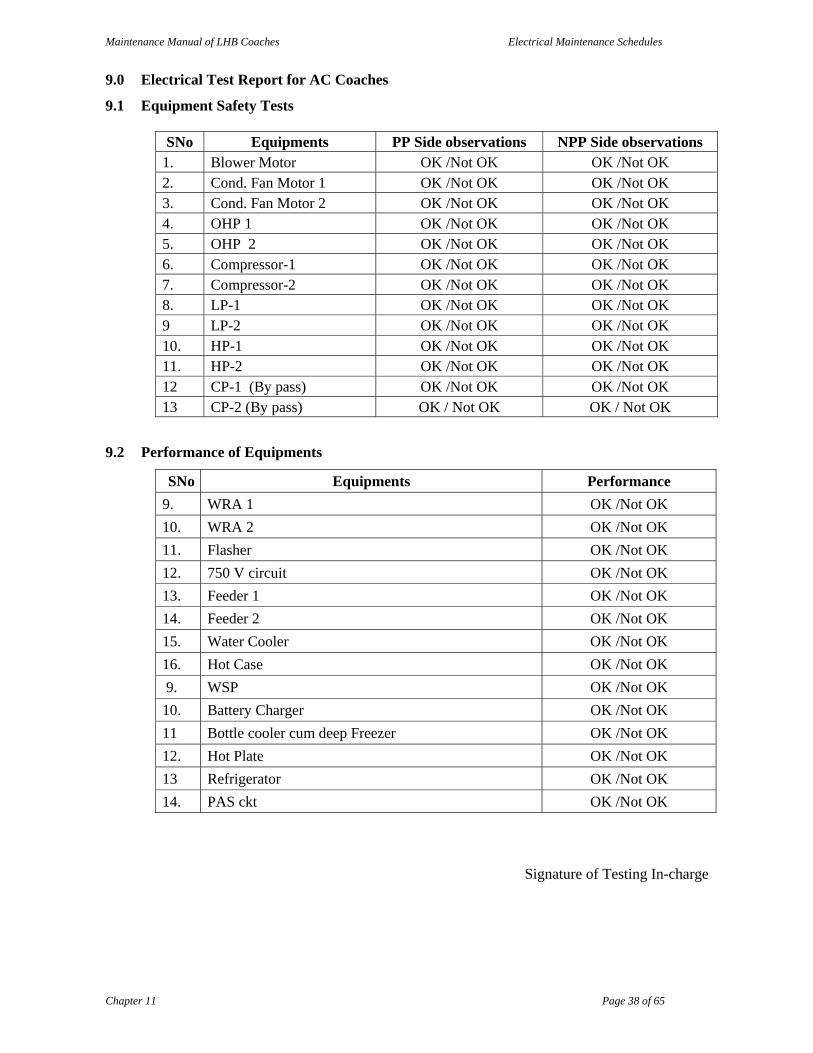
9.0 Electrical Test Report for AC Coaches
9.1 Equipment Safety Tests
SNo Equipments PP Side observations NPP Side observations 1. Blower Motor OK /Not OK OK /Not OK 2. Cond. Fan Motor 1 OK /Not OK OK /Not OK 3. Cond. Fan Motor 2 OK /Not OK OK /Not OK 4. OHP 1 OK /Not OK OK /Not OK 5. OHP 2 OK /Not OK OK /Not OK 6. Compressor-1 OK /Not OK OK /Not OK 7. Compressor-2 OK /Not OK OK /Not OK 8. LP-1 OK /Not OK OK /Not OK 9 LP-2 OK /Not OK OK /Not OK 10. HP-1 OK /Not OK OK /Not OK 11. HP-2 OK /Not OK OK /Not OK 12 CP-1 (By pass) OK /Not OK OK /Not OK 13 CP-2 (By pass) OK / Not OK OK / Not OK
9.2 Performance of Equipments
SNo Equipments Performance
9. WRA 1 OK /Not OK
10. WRA 2 OK /Not OK
11. Flasher OK /Not OK
12. 750 V circuit OK /Not OK
13. Feeder 1 OK /Not OK
14. Feeder 2 OK /Not OK
15. Water Cooler OK /Not OK
16. Hot Case OK /Not OK
9. WSP OK /Not OK
10. Battery Charger OK /Not OK
11 Bottle cooler cum deep Freezer OK /Not OK
12. Hot Plate OK /Not OK
13 Refrigerator OK /Not OK
14. PAS ckt OK /Not OK
Signature of Testing In-charge

Maintenance Manual of LHB Coaches Electrical Maintenance Schedules
Chapter 11 Page 39 of 65
Annexure-11.4
SAMPLE CALCULATION FOR CALCULATING COMPENSATING LOAD
To find out electrical compensating load to be provided inside the coach when coach is
tested at other than the designed outside ambient condition say 40º C (104 ºF) DB and 30 ºC (86º F) WB
Coach: Self generating chair car to CSC layout No. 1559 for 71 passengers.
Designed (outside) conditions = 45 º C (113 º F) DB & 25ºC (77ºF) WB
Designed (outside) conditions = 25 ºC (77 ºF) DR & 40% RH A. Heat gain inside the coach at designed conditions:
i. Conduction = 11,045 B.Th.U/hrs.
Formulae = Area x Overall coefficient of heat transfer in B. Th.U/ hr/ ºF/ sq.ft x temperature difference
a) Side wall = 2 x 236 x 0.127 x 36 = 2980.944
b) End partition walls = 2 x 73 x 0.127 x 31 = 667.512
c) Roof = 550 x 0.134 x 36 = 2653.2
d) Floor = 514 x 0.149 x 36 = 2757.096
e) Windows = 2 x 69 x 0.4 x 36 = 1987.2
Where 0.127 is the factor for heat transfer through walls, 0.134 is for roof and 0.149 is for the floors. For glass windows the factor for heat transfer has been taken as 0.4.
ii) Solar radiation = 15193.4 B.Th.U/ hrs.
Formula = Area x Overall coefficient of heat transfer x solar temperature difference
a) Side wall = 326 x 0. 127 x 16 = 662.4
b) Roof = 550 x 0.134 x 19 = 1400.3
c) Windows = 69 x 1.1 x 173 = 13130.7
Where 16.19 & 173 are the solar temperature differences as per tranes air-conditioning manual page 314 and 315 for 30 ºC N latitude at 16 hrs.
iii) Passengers (@ 400 B. Th. C = 28,400 B.Th.U / hr per passenger 71 x 400)
iv) Light and fans (3.4 B.Th.U/ hrs = 8,275 B. Th. U/ hr per watt for lights and 3600 B.Th.U/hrs for small motors)
a) Tube lights = 22 x 30 x 3.4 = 2244 B.Th.U/hr
b) Carriage fans = (8 x 35 x 3600)/ 746 = 1351 B.Th.U/hr
c) Blower motor = 2 x 0.65 x 3600 = 4680 B.Th.U/hr

Maintenance Manual of LHB Coaches Electrical Maintenance Schedules
Chapter 11 Page 40 of 65
v) Ventilation = 51,365 B.Th.U/hr
a) Sensible = 1.1 x Nos. of person x cfm of air per person x temperature difference.
= 1.1 x 71 x 12.4 x 36
= 34864 B.Th.U/hr
b) Latent = 0.68 x No. of person x cfm of per person x difference of grains of moisture between
outside air & conditioned air. **
= 0.68 x 71 x 12.4 x (82 - 56)
= 16501 B.Th.U/hr
Formula = For sensible heat gain as per tranes air conditioning manual page 88 and for latent heat gain formula 23 on page 150 of carrier handbook of air conditioning and ventilation.
Total heat gain = 1,14,729 B.Th.U/hr
Adding 10% for leakage = 1,25,707 B.Th.U/hr
heat gain B) Heat gain during test at outside ambient = 104 - 77
Conditions of 40 º C (DB) and 30 ºC = 27 º C
(WB) temperature difference
i) Conduction = (11046 x 27)/ 36 = 8284 B.Th.U/hrs
ii) Light & fan = 8275 B.Th.U/hrs
iii) Ventilation
a) Sensible = (34867 x 27)/ 36 = 26148 B.Th.U/hrs
b) Latent = 0.68 x 71 x 12.4 x (161-56)**
= 62861 B.Th.U/hrs
Total heat gain under actual test condition = 105568 B.Th.U/hrs
Therefore electrical load to be = 125707-105568 B.Th.U/hrs
provided inside the coach to
produce heat units = 20, 139 B.Th.U/hrs
Therefore electrical load in kW = 20139/ (3.41 x 1000)
= 5.906 kW
** To be determined from the outside and inside conditions on physcrometic chart.

Maintenance Manual of LHB Coaches Electrical Maintenance Schedules
Chapter 11 Page 41 of 65
Annexure – 11.5
PROFORMA TO RECORD PULL DOWN TEST 1. Type and Coach No. …………
2. Supply Voltage …………V
3. Ambient temperature ………….DB…….WB
4. Electrical compensating heat load provided ………….kW
Temp setting
at position 6 (i.e.24.04°C)
Time when Compensating Electric Load switched ‘ON’
Time when both
plants switched
‘ON’
Coach temperature
when bothplants
switched ‘ON’
Time of plants cutting ‘OFF’
Coach temperature
when both plants switched ‘OFF’
Plant 1 Plant 2 Plant 1 Plant 2
45º C
Total time taken by both plants to switch ‘OFF’
PP side ………………....min.
NPP side ……………….min.
Signature of Testing In-charge
Maintenance Manual of LHB Coaches Electrical Maintenance Schedules
Chapter 11 Page 42 of 65
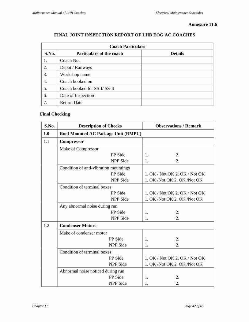
Annexure 11.6
FINAL JOINT INSPECTION REPORT OF LHB EOG AC COACHES
Coach Particulars
S.No. Particulars of the coach Details
1. Coach No.
2. Depot / Railways
3. Workshop name
4. Coach booked on
5. Coach booked for SS-I/ SS-II
6. Date of Inspection
7. Return Date
Final Checking
S.No. Description of Checks Observations / Remark
1.0 Roof Mounted AC Package Unit (RMPU)
1.1 Compressor
Make of Compressor PP Side NPP Side
1. 2. 1. 2.
Condition of anti-vibration mountings PP Side NPP Side
1. OK / Not OK 2. OK / Not OK 1. OK /Not OK 2. OK /Not OK
Condition of terminal boxes PP Side NPP Side
1. OK / Not OK 2. OK / Not OK 1. OK /Not OK 2. OK /Not OK
Any abnormal noise during run PP Side NPP Side
1. 2. 1. 2.
1.2 Condenser Motors
Make of condenser motor PP Side NPP Side
1. 2. 1. 2.
Condition of terminal boxes PP Side NPP Side
1. OK / Not OK 2. OK / Not OK 1. OK /Not OK 2. OK /Not OK
Abnormal noise noticed during run PP Side NPP Side
1. 2. 1. 2.
Maintenance Manual of LHB Coaches Electrical Maintenance Schedules
Chapter 11 Page 43 of 65
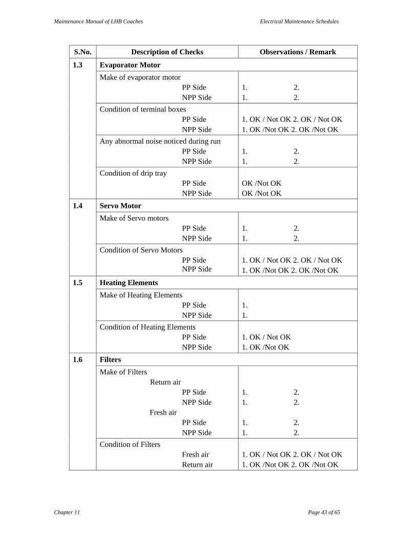
S.No. Description of Checks Observations / Remark
1.3 Evaporator Motor
Make of evaporator motor PP Side NPP Side
1. 2. 1. 2.
Condition of terminal boxes PP Side NPP Side
1. OK / Not OK 2. OK / Not OK 1. OK /Not OK 2. OK /Not OK
Any abnormal noise noticed during run PP Side NPP Side
1. 2. 1. 2.
Condition of drip tray PP Side NPP Side
OK /Not OK OK /Not OK
1.4 Servo Motor
Make of Servo motors PP Side NPP Side
1. 2. 1. 2.
Condition of Servo Motors PP Side NPP Side
1. OK / Not OK 2. OK / Not OK 1. OK /Not OK 2. OK /Not OK
1.5 Heating Elements
Make of Heating Elements PP Side NPP Side
1. 1.
Condition of Heating Elements PP Side NPP Side
1. OK / Not OK 1. OK /Not OK
1.6 Filters
Make of Filters Return air
PP Side NPP Side
Fresh air PP Side NPP Side
1. 2. 1. 2. 1. 2. 1. 2.
Condition of Filters Fresh air Return air
1. OK / Not OK 2. OK / Not OK 1. OK /Not OK 2. OK /Not OK

Maintenance Manual of LHB Coaches Electrical Maintenance Schedules
Chapter 11 Page 44 of 65
S.No. Description of Checks Observations / Remark
1.7 Protection Devices
Condition of HP output PP Side NPP Side
1. OK / Not OK 2. OK / Not OK 1. OK /Not OK 2. OK /Not OK
Condition of LP cutouts PP Side NPP Side
1. OK / Not OK 2. OK / Not OK 1. OK /Not OK 2. OK /Not OK
Condition of control pressure switch PP Side NPP Side
OK /Not OK OK /Not OK
Condition of ESTI fusible link PP Side NPP Side
OK / Not OK OK / Not OK
Condition of OHP PP Side NPP Side
OK / Not OK OK / Not OK
Condition of temperature sensors PP Side NPP Side
OK / Not OK OK / Not OK
Condition of humidity sensors PP Side NPP Side
OK / Not OK OK / Not OK
1.8 Refrigerant Pipe Line
Condition of Clamping of pipe line PP Side NPP Side
OK / Not OK OK / Not OK
2.0 Switch Board Cabinet
Condition of rotary switches OK / Not OK
Condition of MCBs for
Light
Fan circuit
Other MCBs
OK / Not OK
OK / Not OK
OK / Not OK
Condition of terminals OK / Not OK
Condition of contractors OK / Not OK
Condition of relays OK / Not OK
Condition of meters
Ammeters
Voltmeters
Pressure Gauges
OK / Not OK
OK / Not OK
OK / Not OK
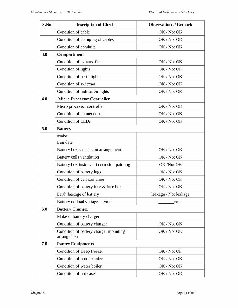
Maintenance Manual of LHB Coaches Electrical Maintenance Schedules
Chapter 11 Page 45 of 65
S.No. Description of Checks Observations / Remark
Condition of cable OK / Not OK
Condition of clamping of cables OK / Not OK
Condition of conduits OK / Not OK
3.0 Compartment
Condition of exhaust fans OK / Not OK
Condition of lights OK / Not OK
Condition of berth lights OK / Not OK
Condition of switches OK / Not OK
Condition of indication lights OK / Not OK
4.0 Micro Processor Controller
Micro processor controller OK / Not OK
Condition of connections OK / Not OK
Condition of LEDs OK / Not OK
5.0 Battery
Make
Lug date
Battery box suspension arrangement OK / Not OK
Battery cells ventilation OK / Not OK
Battery box inside anti corrosion painting OK /Not OK
Condition of battery lugs OK / Not OK
Condition of cell container OK / Not OK
Condition of battery fuse & fuse box OK / Not OK
Earth leakage of battery leakage / Not leakage
Battery no load voltage in volts _______volts
6.0 Battery Charger
Make of battery charger
Condition of battery charger OK / Not OK
Condition of battery charger mounting arrangement
OK / Not OK
7.0 Pantry Equipments
Condition of Deep freezer OK / Not OK
Condition of bottle cooler OK / Not OK
Condition of water boiler OK / Not OK
Condition of hot case OK / Not OK
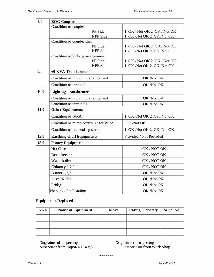
Maintenance Manual of LHB Coaches Electrical Maintenance Schedules
Chapter 11 Page 46 of 65
8.0 EOG Coupler Condition of coupler
PP Side NPP Side
1. OK / Not OK 2. OK / Not OK 1. OK /Not OK 2. OK /Not OK
Condition of coupler pins PP Side NPP Side
1. OK / Not OK 2. OK / Not OK 1. OK /Not OK 2. OK /Not OK
Condition of locking arrangement PP Side NPP Side
1. OK / Not OK 2. OK / Not OK 1. OK /Not OK 2. OK /Not OK
9.0 60 KVA Transformer
Condition of mounting arrangement OK /Not OK
Condition of terminals OK /Not OK
10.0 Lighting Transformer
Condition of mounting arrangement OK /Not OK
Condition of terminals OK /Not OK
11.0 Other Equipments
Condition of WRA 1. OK /Not OK 2. OK /Not OK
Condition of micro controller for WRA OK /Not OK
Condition of pre cooling socket 1. OK /Not OK 2. OK /Not OK
12.0 Earthing of all Equipments Provided / Not Provided
13.0 Pantry Equipments
Hot Case OK / NOT OK
Deep freezer OK / NOT OK
Water boiler OK / NOT OK
Chimney 1,2,3 OK / NOT OK
Burner 1,2,3 OK /Not OK
Insect Killer OK /Not OK
Fridge OK /Not OK
Working of call station OK /Not OK
Equipments Replaced
S.No Name of Equipment Make Rating/ Capacity Serial No.
(Signature of Inspecting (Signature of Inspecting Supervisor from Depot/ Railway) Supervisor from Work Shop)
*******

Maintenance Manual of LHB Coaches Electrical Maintenance Schedules
Chapter 11 Page 47 of 65
Annexure 11.7 LIST OF MUST CHANGE ITEMS FOR LHB AC COACHES
S.No. Items First POH
Second POH
1
Switch Board Cabinet a MCBs for Pantry Equipments,F-16,F-18, F-19,F-20 Y b MCBs for Pump Controller F-36 Y c MCBs for Compressors F-03,F-05,F-09,F-11 Y d MPCB for Pumps, F-21 & F-22 Y e Contactor for Compressor K-33, K-34, K-38, K-39 Y f Contactor for Blower Fan Motor K-26,K-28 Y
g Contactor for Condenser Fan Motor K-31,K-32, K-36, K-37
Y
h Contactor for Heater K-35,K-40 Y i Contactor for Output of 60KVA Transformer, K-44 Y j Timer for External Power Supply/LMS, K-18 Y k Timer for Light ON/OFF, K-17 Y l Minimum Voltage Relay(MVR), U-2.3 Y
m Rotary Switch for Disconnecting & Earth Device,A-2
Y
n DC to DC converter (110V/24V) for Pump control & Sanitary control, U-2.1
Y
o Rotary Switch Power Supply ON/OFF, S-01 Y
p Rotary Selector Switch Net-1,Net-2 & LMS, S-02
Y
q Interlock Contactor for Changeover of Coach light supply from 110V AC to 110V DC & Vice versa, K-48
Y
r Measuring & Monitoring Relay MMRs, K-03 & K-04
Y
s Main Feeder Contactors, K-01 & K-02 Y t Electronic Module for Contactors, K-01, K-02 Y u Door for complete Switch Cabinet unit Y
2
Light Fittings a Lavatory Light Fitting Y b Lavatory Exhaust Fan Y c Diffuser for Rajdhani Exp Coaches Y d Mobile Switch Socket complete Y
3
Pantry Equipments a 3Pin Sockets/MCBs for operation of equipments Y b Hot Water Boiler/Geyser Y
c Heating Element assembly complete with Blower unit rotary switch, thermostat & indicator for Hot cases
Y
d Filter of Electric Chemney Y e Pantry Exhaust Fan Y
Maintenance Manual of LHB Coaches Electrical Maintenance Schedules
Chapter 11 Page 48 of 65
4
Roof Mounted AC Package Unit a Canvas Duct for Return Air Y b Canvas Duct for Supply Air Y c Canvas Duct for Fresh Air Y d Anti Vibration Mounting Pad Y e Filter media mix air Y f Filter cassette Fresh air Y g ESTI cartridge Bulb Y h Over Heat Protection Switch Y i NTC sensors Y j Thermal Insulation Sheet Y k Earthing Shunt Y l Rotary Switch ON/OFF for AC plant Y m Fresh Air Filter Assembly Y n FRP Blade for Condenser Fan Blade Y
5
ZS Coupling
a Contact Pin assembly for Phases, Neutral & Earth with Springs
Y
b Connector Female assembly Phases, Neutral & Earth with Springs
Y
c Ratchet arrangement for coupling sockets assembly Y
d Insulating Base with fixing screw kit for coupling socket
Y
e Insulating Base with fixing screw kit for Jumper Plug assembly
Y
f Hinged cover assembly for Blind socket Y g Ratchet arrangement for Blind socket assembly Y h PMA protective sleeve for cables Y i Conduit seal ring & all type gaskets Y j Coupling socket housing assembly Y k Lever Tie Bow RH & LH Y l Connecting link lever arm Y m Rivet Pin link long Y
n Complete ZS coupling with ratchet sockets assembly & Blind socket
Y
6 Monoblock Pump a Complete Monoblock Pump unit Y
7 Battery Fuse Box a Positive Battery Fuse Box Complete Y b Nagetive Battery Fuse Box Complete Y
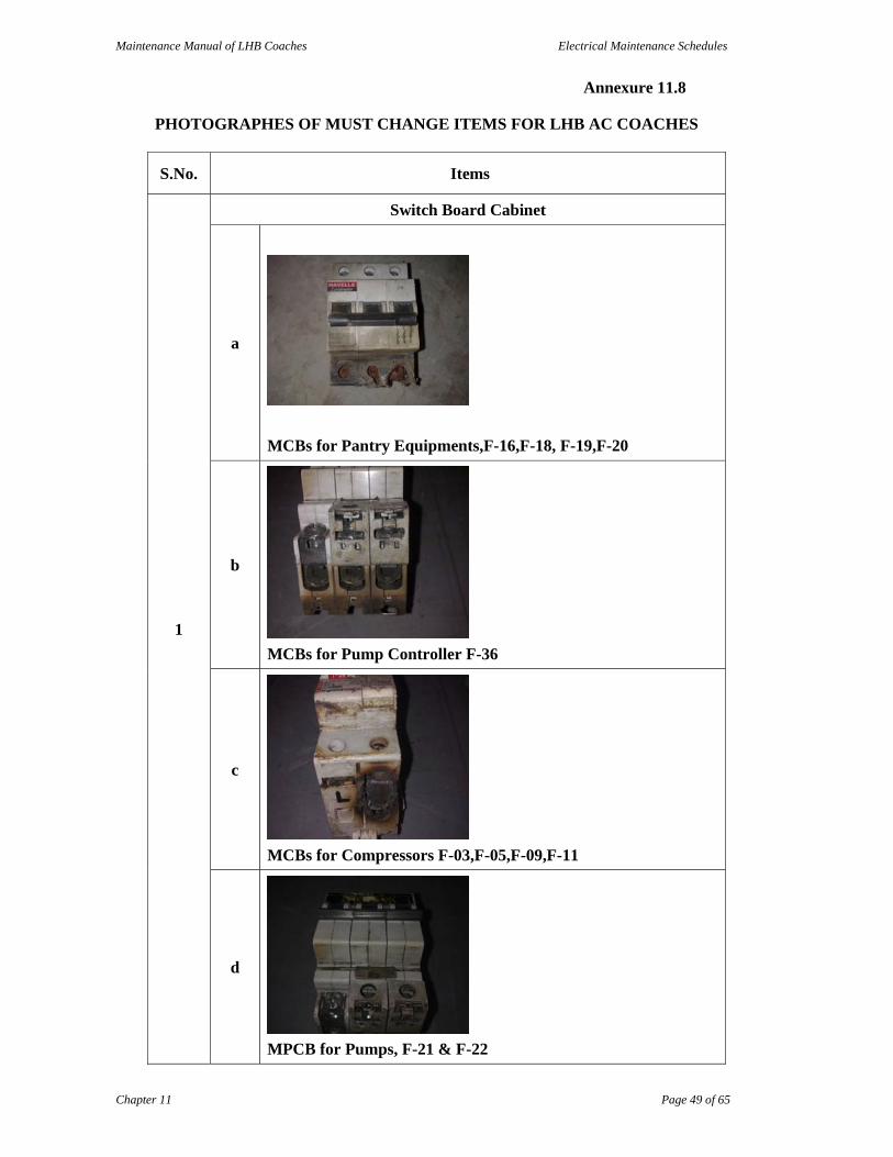
Maintenance Manual of LHB Coaches Electrical Maintenance Schedules
Chapter 11 Page 49 of 65
Annexure 11.8 PHOTOGRAPHES OF MUST CHANGE ITEMS FOR LHB AC COACHES
S.No. Items
1
Switch Board Cabinet
a
MCBs for Pantry Equipments,F-16,F-18, F-19,F-20
b
MCBs for Pump Controller F-36
c
MCBs for Compressors F-03,F-05,F-09,F-11
d
MPCB for Pumps, F-21 & F-22
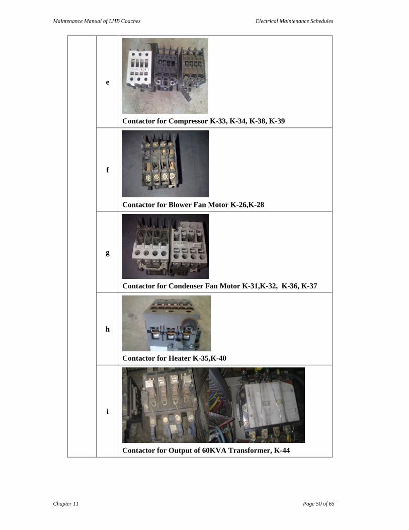
Maintenance Manual of LHB Coaches Electrical Maintenance Schedules
Chapter 11 Page 50 of 65
e
Contactor for Compressor K-33, K-34, K-38, K-39
f
Contactor for Blower Fan Motor K-26,K-28
g
Contactor for Condenser Fan Motor K-31,K-32, K-36, K-37
h
Contactor for Heater K-35,K-40
i
Contactor for Output of 60KVA Transformer, K-44

Maintenance Manual of LHB Coaches Electrical Maintenance Schedules
Chapter 11 Page 51 of 65
j
Upper Spring
Upper Housing Feeder Contactor Spring
k
Return Spring
Return Housing Feeder Contactor Spring
l
Return Spring
Return Housing Contactor Spring
m
Timer for External Power Supply/LMS, K-18
l
Timer for Light ON/OFF, K-17
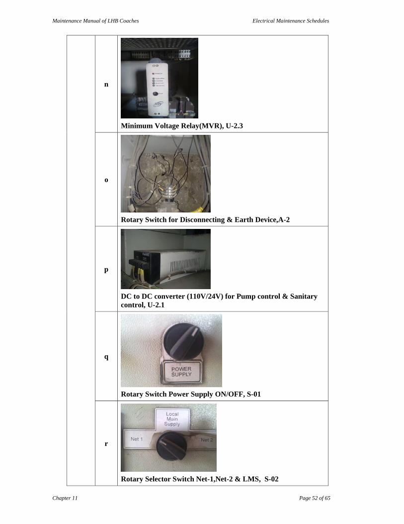
Maintenance Manual of LHB Coaches Electrical Maintenance Schedules
Chapter 11 Page 52 of 65
n
Minimum Voltage Relay(MVR), U-2.3
o
Rotary Switch for Disconnecting & Earth Device,A-2
p
DC to DC converter (110V/24V) for Pump control & Sanitary control, U-2.1
q
Rotary Switch Power Supply ON/OFF, S-01
r
Rotary Selector Switch Net-1,Net-2 & LMS, S-02

Maintenance Manual of LHB Coaches Electrical Maintenance Schedules
Chapter 11 Page 53 of 65
s
Interlock Contactor for Changeover of Coach light supply from 110V AC to 110V DC & Vice versa, K-48
t Measuring & Monitoring Relay MMRs, K-03 & K-04
u
Main Feeder Contactors, K‐01 & K‐02
v
Electronic Module for Contactors, K-01, K-02
w
Door for complete Switch Cabinet unit
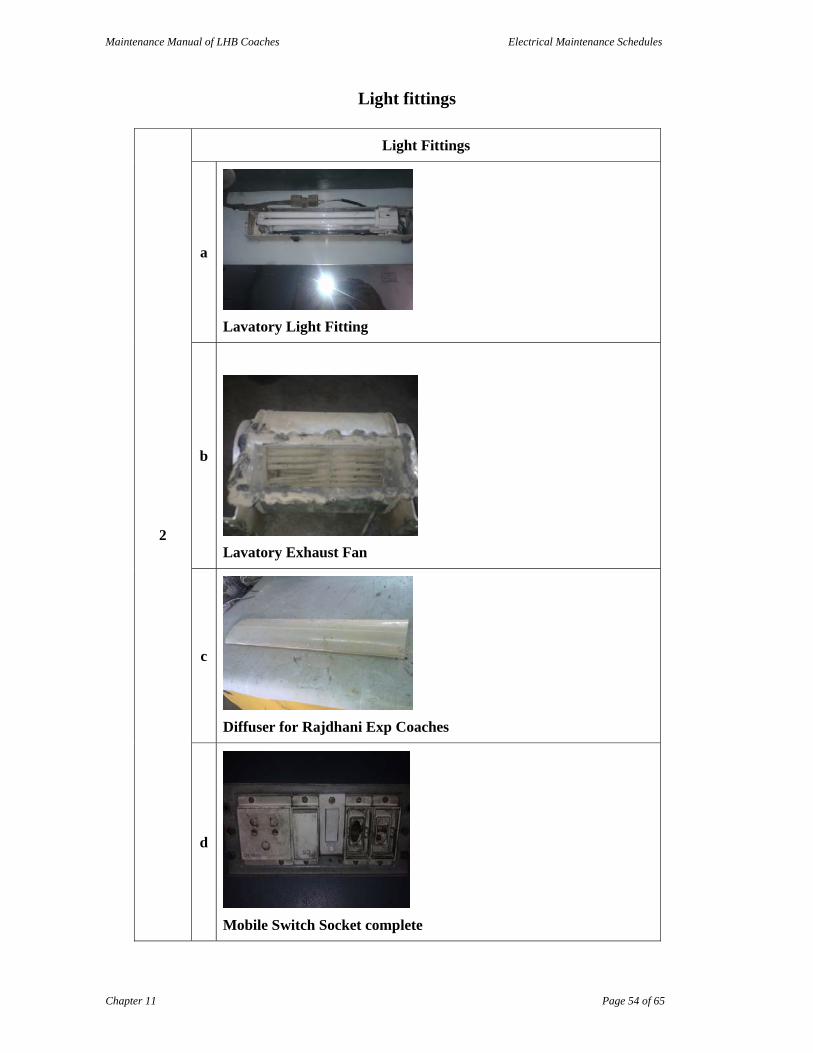
Maintenance Manual of LHB Coaches Electrical Maintenance Schedules
Chapter 11 Page 54 of 65
Light fittings
2
Light Fittings
a
Lavatory Light Fitting
b
Lavatory Exhaust Fan
c
Diffuser for Rajdhani Exp Coaches
d
Mobile Switch Socket complete

Maintenance Manual of LHB Coaches Electrical Maintenance Schedules
Chapter 11 Page 55 of 65
Pantry Equipment
3
Pantry Equipment
a
3Pin Sockets/MCBs for operation of equipment
b
Hot Water Boiler/Geyser
c
Heating Element assembly complete with Blower unit rotary switch, thermostat & indicator for Hot cases
d
Filter of Electric Chimney
e
Pantry Exhaust Fan

Maintenance Manual of LHB Coaches Electrical Maintenance Schedules
Chapter 11 Page 56 of 65
ZS Coupling
5
ZS Coupling
a
Contact Pin assembly for Phases, Neutral & Earth with Springs
b
Connector Female assembly Phases, Neutral & Earth with Springs
c
Ratchet arrangement for coupling sockets assembly
d
Insulating Base with fixing screw kit for coupling socket
e
Insulating Base with fixing screw kit for Jumper Plug assembly

Maintenance Manual of LHB Coaches Electrical Maintenance Schedules
Chapter 11 Page 57 of 65
f
Hinged cover assembly for Blind socket
g
Ratchet arrangement for Blind socket assembly
h
PMA protective sleeve for cables
i
Conduit seal ring & all type gaskets
j
Coupling socket housing assembly
k
Lever Tie Bow RH & LH

Maintenance Manual of LHB Coaches Electrical Maintenance Schedules
Chapter 11 Page 58 of 65
l
Connecting link lever arm
m
Rivet Pin link long
n
Complete ZS coupling with ratchet sockets assembly & Blind socket
Mono block Pump
6
Mono block Pump
a
Complete Monoblock Pump unit

Maintenance Manual of LHB Coaches Electrical Maintenance Schedules
Chapter 11 Page 59 of 65
Battery Fuse Box
7
Battery Fuse Box
a
Positive Battery Fuse Box Complete
b
Nagetive Battery Fuse Box Complete

Maintenance Manual of LHB Coaches Electrical Maintenance Schedules
Chapter 11 Page 60 of 65
Annexure 11.9
ELECTRICAL TOOLS, MACHINE & PLANT
The facilities mentioned below are bare minimum. However, if some facilities are already available (either in mechanical or electrical sick line) only supplementing would be necessary. Effort should always be made to complete both electrical and mechanical maintenance in single placement of the rake. A. REPAIRING & TESTING FACILITIES
S.N. ITEM COACH HOLDING
0-50 51-100 101-250 251-500 501-1000
1. Engine sub assemblies repairing & calibration facilities
1 1 2 2 3
2. FIP pump & injector repairing, testing and calibration facilities
1 1 2 2 3
3. I.V. coupler/ HOG coupler & ratchet wheel repairing and testing facilities
1 1 1 2 2
4. Filter cleaning arrangements with blower & water sump for cleaning/ drying air filters
1 1 2 2 2
5. Radiator cleaning tank size 2W x 4L x 2D (in meters).
-- 1 1 1 1
6. Condenser cleaning tank size 2W x 4L x 2D (in meters).
-- 1 1 1 1
7. Microprocessor based Electronic card reading and repairing facilities.
-- -- 1 1 1
8. HSD oil decantation facility with pump for generator car shed of suitable capacity.
-- 1 1 1 1
9. 500 kW load testing facility for power car (Inductive/ Resistive)
1 1 2 2 2
10. Test bench for Diesel engine (Dynamometer type)
1 1 2 2 2
11. Test bench for on load testing of Alternator of power car
-- -- 1 1 1
12. Testing supply points 750V 3 phase At each coach length
13. Portable Step up transformer 415/750, 50/60kVA
1 1 2 2 4
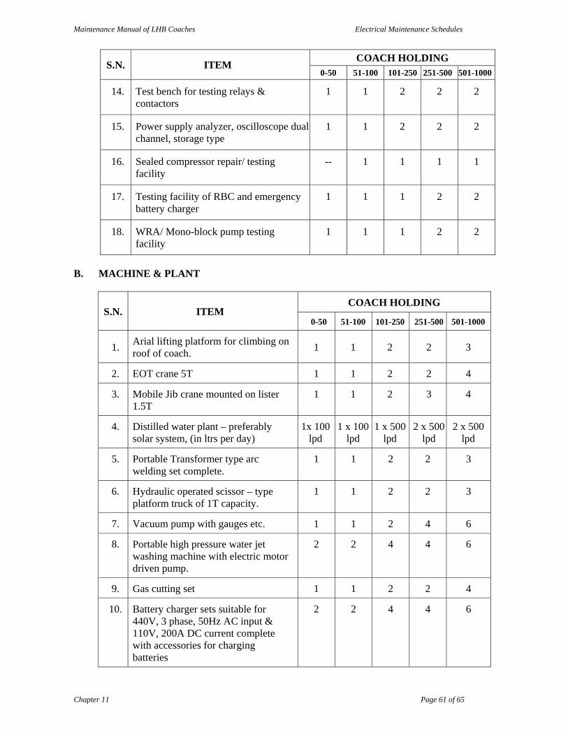
Maintenance Manual of LHB Coaches Electrical Maintenance Schedules
Chapter 11 Page 61 of 65
S.N. ITEM COACH HOLDING
0-50 51-100 101-250 251-500 501-1000
14. Test bench for testing relays & contactors
1 1 2 2 2
15. Power supply analyzer, oscilloscope dual channel, storage type
1 1 2 2 2
16. Sealed compressor repair/ testing facility
-- 1 1 1 1
17. Testing facility of RBC and emergency battery charger
1 1 1 2 2
18. WRA/ Mono-block pump testing facility
1 1 1 2 2
B. MACHINE & PLANT
S.N. ITEM COACH HOLDING
0-50 51-100 101-250 251-500 501-1000
1. Arial lifting platform for climbing on roof of coach.
1 1 2 2 3
2. EOT crane 5T 1 1 2 2 4
3. Mobile Jib crane mounted on lister 1.5T
1 1 2 3 4
4. Distilled water plant – preferably solar system, (in ltrs per day)
1x 100 lpd
1 x 100 lpd
1 x 500 lpd
2 x 500 lpd
2 x 500 lpd
5. Portable Transformer type arc welding set complete.
1 1 2 2 3
6. Hydraulic operated scissor – type platform truck of 1T capacity.
1 1 2 2 3
7. Vacuum pump with gauges etc. 1 1 2 4 6
8. Portable high pressure water jet washing machine with electric motor driven pump.
2 2 4 4 6
9. Gas cutting set 1 1 2 2 4
10. Battery charger sets suitable for 440V, 3 phase, 50Hz AC input & 110V, 200A DC current complete with accessories for charging batteries
2 2 4 4 6
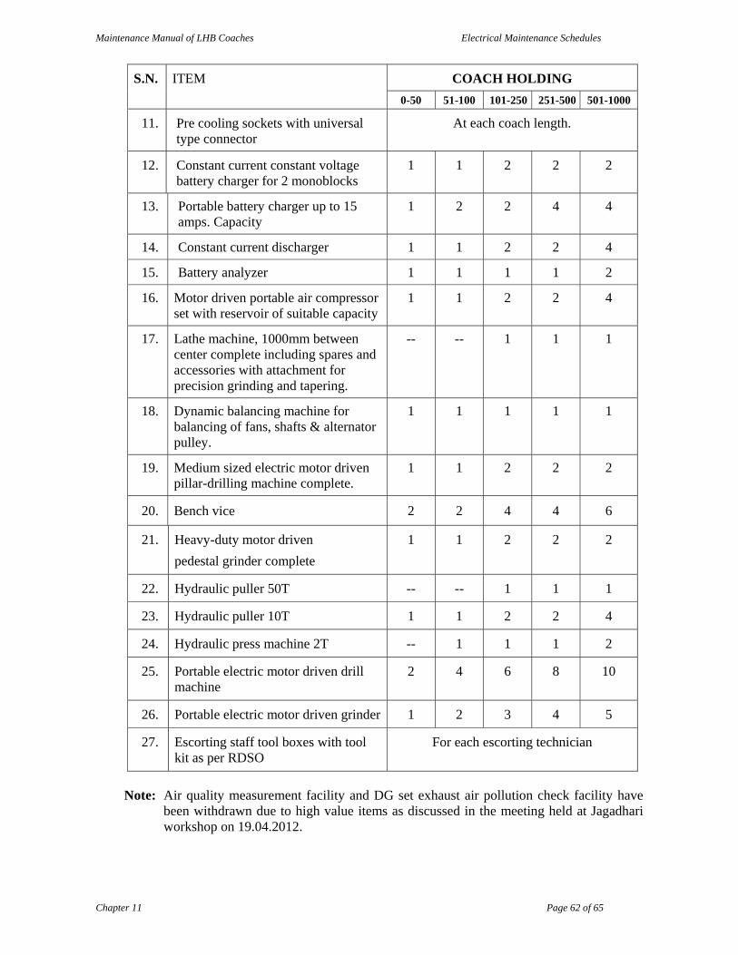
Maintenance Manual of LHB Coaches Electrical Maintenance Schedules
Chapter 11 Page 62 of 65
S.N. ITEM COACH HOLDING
0-50 51-100 101-250 251-500 501-1000
11. Pre cooling sockets with universal type connector
At each coach length.
12. Constant current constant voltage battery charger for 2 monoblocks
1 1 2 2 2
13. Portable battery charger up to 15 amps. Capacity
1 2 2 4 4
14. Constant current discharger 1 1 2 2 4
15. Battery analyzer 1 1 1 1 2
16. Motor driven portable air compressor set with reservoir of suitable capacity
1 1 2 2 4
17. Lathe machine, 1000mm between center complete including spares and accessories with attachment for precision grinding and tapering.
-- -- 1 1 1
18. Dynamic balancing machine for balancing of fans, shafts & alternator pulley.
1 1 1 1 1
19. Medium sized electric motor driven pillar-drilling machine complete.
1 1 2 2 2
20. Bench vice 2 2 4 4 6
21. Heavy-duty motor driven
pedestal grinder complete
1 1 2 2 2
22. Hydraulic puller 50T -- -- 1 1 1
23. Hydraulic puller 10T 1 1 2 2 4
24. Hydraulic press machine 2T -- 1 1 1 2
25. Portable electric motor driven drill machine
2 4 6 8 10
26. Portable electric motor driven grinder 1 2 3 4 5
27. Escorting staff tool boxes with tool kit as per RDSO
For each escorting technician
Note: Air quality measurement facility and DG set exhaust air pollution check facility have
been withdrawn due to high value items as discussed in the meeting held at Jagadhari workshop on 19.04.2012.

Maintenance Manual of LHB Coaches Electrical Maintenance Schedules
Chapter 11 Page 63 of 65
S.N. ITEM COACH HOLDING
0-50 51-100 101-250 251-500 501-1000
28. Motorised Megger upto 2.5 kV 1 2 2 4 4
29. Vacuum cleaner industrial type 1 2 2 4 4
30. Refrigerant recovery plant 1 1 2 2 4
31. Electronic weighing machine up to 15kg
1 1 2 2 3
32. Electronic weighing machine up to 500kg
1 1 2 2 3
33. Testing equipment (variable voltage supply AC & DC, transistor tester, meter testing kit etc.)
2 2 4 4 6
34. Electric motor driven de-watering pump set for pits.
1 1 2 2 2
35. Portable electric motor driven blower
2 2 4 4 6
36. 46.7 Ltrs spare oxygen (7 m3 ) cylinders
2 4 4 8 15
37. 41 Ltrs spare Acetylene (5.5 m3 ) gas cylinders
2 4 8 8 15
38. 46.7 Ltrs spare Nitrogen (7 m3 ) gas cylinders
2 4 8 8 15
39. Spare R-134a refrigerant cylinders 4 6 8 10 15
40. Oven for drying electrical motor etc. size as per requirement.
1 1 1 1 1
41. DG set, 415V of adequate capacity as standby power supply.
1 1 1 1 1
42. Step up transformer 415V/ 750 V of adequate capacity as standby power supply.
1 1 1 1 1
43. 415V/ 750 V power supply points along the pit
At each coach length
44. Injector testing & calibration machine.
1 1 2 2 2
45. Injector leakage testing machine 1 2 2 4 6
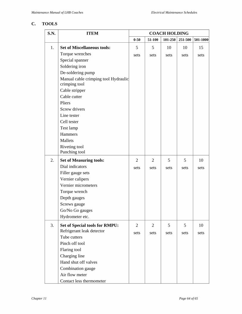
Maintenance Manual of LHB Coaches Electrical Maintenance Schedules
Chapter 11 Page 64 of 65
C. TOOLS
S.N. ITEM COACH HOLDING 0-50 51-100 101-250 251-500 501-1000
1. Set of Miscellaneous tools:
Torque wrenches
Special spanner
Soldering iron
De-soldering pump
Manual cable crimping tool Hydraulic crimping tool
Cable stripper
Cable cutter
Pliers
Screw drivers
Line tester
Cell tester
Test lamp
Hammers
Mallets
Riveting tool Punching tool
5
sets
5
sets
10
sets
10
sets
15
sets
2. Set of Measuring tools:
Dial indicators
Filler gauge sets
Vernier calipers
Vernier micrometers
Torque wrench
Depth gauges
Screws gauge
Go/No Go gauges
Hydrometer etc.
2
sets
2
sets
5
sets
5
sets
10
sets
3. Set of Special tools for RMPU: Refrigerant leak detector
Tube cutters
Pinch off tool
Flaring tool
Charging line
Hand shut off valves
Combination gauge
Air flow meter
Contact less thermometer
2
sets
2
sets
5
sets
5
sets
10
sets

Maintenance Manual of LHB Coaches Electrical Maintenance Schedules
Chapter 11 Page 65 of 65
S.N. ITEM COACH HOLDING 0-50 51-100 101-250 251-500 501-1000
LP gauge
HP gauge
Tube bender
Lapping machine
4. Set of Electrical testing tools:
Digital multi meters
Industrial grade AC & DC voltmeters
Industrial grade AC & DC ammeter
Digital tongue tester
Insulation tester
Contact less thermometer
Digital thermometer
Infrared thermometer
Non contact type digital tachometer
Anemometer
Hygrometer
Lux meter
2
sets
2
sets
5
sets
5
sets
10
sets
5. Digital dB meter (Noise level indicator)
2 2 2 4 6
6. Shock pulse meter 1 2 3 4 6
7. Techcometer 1 1 1 2 2
D. SAFETY EQUIPMENTS
S.N. ITEM COACH HOLDING
0-50 51-100 101-250 251-500 501-1000
1. All workmen safety equipments such as industrial helmets, hand gloves, industrial shoes, nose masks, minor light etc.
As per requirement
2. Fire extinguishers, sand buckets with stand
As per requirement
3. Safety belts for working on the roof of the coach.
As per requirement
4. First aid boxes As per requirement
Related Documents