Maintaining Integrity of FPSO Mooring System Dr Dmitry Sadovnikov, Piotr Sujkowski, Dr Yuriy Drobyshevski INTECSEA (Perth), WorleyParsons Group ABSTRACT This paper demonstrates the importance of having ready a mooring integrity management plan, including a mooring failure rapid response plan, to ensure that potential anomalies on a moored FPSO can be addressed quickly with minimum impact on production. An overview of a typical mooring integrity management plan that includes the sparing strategy, mooring replacement procedures and plans for mobilisation of construction vessels is presented for FPSO spread mooring and turret mooring systems. Two major components of the mooring failure rapid response plan, the assessment of the mooring system residual capacity after mooring leg failure and the development of the mooring line replacement procedures, are illustrated using two examples. The mooring residual capacity study, undertaken for a generic FPSO with a disconnectable turret mooring system operated in the North West Shelf of Western Australia, has been used as an example. This paper shows the methodology and main results from the advanced mooring analysis used to determine the residual capacity of the mooring system and the associated limiting weather conditions, which may be used when deciding whether FPSO can safely continue to operate after the loss of one mooring line until permanent repairs are carried out. An example of generic mooring line replacement procedures is shown for a spread-moored FPSO in 1000 metres water depth. Typical methodology of replacing the mooring leg, including a suction pile and a long wire rope, is presented. The paper concludes that preparedness of an FPSO operator, prior modelling and analysis of the mooring and riser systems and availability of up-to-date analytical models are essential for the rapid response activities to be efficiently undertaken after a mooring failure. 1 INTRODUCTION Mooring system of floating production storage and offloading facility (FPSO) provides station keeping for the asset during production, maintaining vessel excursions within allowable limits for the operation of risers and hydrocarbons offloading under anticipated metocean conditions. There are two main types of FPSO mooring systems—permanently connected and disconnectable—used for different types of metocean conditions. Permanent mooring systems are typically designed for FPSOs staying on station in non-cyclonic environments for the duration of its design life (for example, in West Africa, South-East Asia or North Sea). Disconnectable mooring systems are typically used for cyclonic environmental conditions (for example, in Western Australia‘s North West Shelf) and allow quick disconnection of the FPSO from the mooring system to evade cyclones. Disconnectable mooring systems are also used for FPSOs in Arctic areas to avoid ultimate ice loads or collision with icebergs. The majority of permanently connected FPSOs in benign environments have spread mooring systems, typically made up of four line clusters, each containing several mooring legs. Permanently moored FPSOs, in harsh environments (for example, in the North Sea), require weather-vaning capabilities and have mooring lines attached to a turret.

Welcome message from author
This document is posted to help you gain knowledge. Please leave a comment to let me know what you think about it! Share it to your friends and learn new things together.
Transcript

Maintaining Integrity of FPSO Mooring
System Dr Dmitry Sadovnikov, Piotr Sujkowski, Dr Yuriy Drobyshevski
INTECSEA (Perth), WorleyParsons Group
ABSTRACT
This paper demonstrates the importance of having ready a mooring integrity management
plan, including a mooring failure rapid response plan, to ensure that potential anomalies on a
moored FPSO can be addressed quickly with minimum impact on production. An overview of
a typical mooring integrity management plan that includes the sparing strategy, mooring
replacement procedures and plans for mobilisation of construction vessels is presented for
FPSO spread mooring and turret mooring systems. Two major components of the mooring
failure rapid response plan, the assessment of the mooring system residual capacity after
mooring leg failure and the development of the mooring line replacement procedures, are
illustrated using two examples. The mooring residual capacity study, undertaken for a generic
FPSO with a disconnectable turret mooring system operated in the North West Shelf of
Western Australia, has been used as an example. This paper shows the methodology and main
results from the advanced mooring analysis used to determine the residual capacity of the
mooring system and the associated limiting weather conditions, which may be used when
deciding whether FPSO can safely continue to operate after the loss of one mooring line until
permanent repairs are carried out. An example of generic mooring line replacement
procedures is shown for a spread-moored FPSO in 1000 metres water depth. Typical
methodology of replacing the mooring leg, including a suction pile and a long wire rope, is
presented. The paper concludes that preparedness of an FPSO operator, prior modelling and
analysis of the mooring and riser systems and availability of up-to-date analytical models are
essential for the rapid response activities to be efficiently undertaken after a mooring failure.
1 INTRODUCTION
Mooring system of floating production storage and offloading facility (FPSO) provides
station keeping for the asset during production, maintaining vessel excursions within
allowable limits for the operation of risers and hydrocarbons offloading under anticipated
metocean conditions.
There are two main types of FPSO mooring systems—permanently connected and
disconnectable—used for different types of metocean conditions. Permanent mooring systems
are typically designed for FPSOs staying on station in non-cyclonic environments for the
duration of its design life (for example, in West Africa, South-East Asia or North Sea).
Disconnectable mooring systems are typically used for cyclonic environmental conditions (for
example, in Western Australia‘s North West Shelf) and allow quick disconnection of the
FPSO from the mooring system to evade cyclones. Disconnectable mooring systems are also
used for FPSOs in Arctic areas to avoid ultimate ice loads or collision with icebergs.
The majority of permanently connected FPSOs in benign environments have spread mooring
systems, typically made up of four line clusters, each containing several mooring legs.
Permanently moored FPSOs, in harsh environments (for example, in the North Sea), require
weather-vaning capabilities and have mooring lines attached to a turret.

Disconnectable FPSO mooring systems typically have a turret with a disconnectable buoy
(DTM buoy) which can be released from the FPSO and then retrieved and locked in the turret
after reconnection. There are internal and external types of mooring turrets located inside the
FPSO hull and mounted on a cantilevered arm protruding forward of the hull respectively.
A typical mooring line make-up includes multiple interconnected components. The integrity
of the mooring leg and, potentially, the whole mooring system depends on each component in
the line. This combination of various components, their individual locations and exposure to
different loads, wear and fatigue make mooring lines a complex system in terms of integrity
management.
Despite the continuing mooring technology development, improvements in engineering
design standards and manufacturing practices, the offshore industry, each year, records
several incidents involving damage or failure of mooring systems. The evidence gathered
throughout the offshore industry suggests that mooring line failure is a relatively common
event during the life cycle of a floating facility and has a high potential of occurrence. North
Sea statistics, collected since the 1980s, indicates that, on average, an FPSO may experience a
mooring failure within 8.8 years of operation [Ref. 13].
The mooring system is an important safety critical component for the FPSO operation.
Therefore its failure—even partial—may have serious consequences, such as risk to the
personnel, damage of risers and possible spill of hydrocarbons caused by exceeding allowable
excursions of the vessel. Although design procedures for FPSO mooring systems require
application of factors of safety for tensions in mooring lines and analysis of a mandatory
damage case [Ref. 4], FPSO operation at the limits of the design environmental conditions
may need to be discontinued if any mooring line has failed or significant abnormalities of
moorings have been detected.
Mooring failure or defect may, therefore, lead to a shutdown and substantial production loss.
These reasons highlight the importance of maintaining the mooring system in good working
order, early detection of abnormalities and prior planning of activities in case of its failure.
This early planning is typically carried out through the development of a Mooring Integrity
Management Plan (MIMP) which is discussed in the following sections of this paper,
including two examples of the plan‘s components.
2 OVERVIEW OF MOORING INTEGRITY MANAGEMENT PLAN
An FPSO specific Mooring Integrity Management Plan (MIMP) typically comprises the
following main modules:
Mooring Inspection Plan (MIP)
Mooring Monitoring Plan (MMP)
Mooring Failure Rapid Response Plan (MFRRP)
Although each of these three modules can be considered as a stand-alone unit or part of the
MIMP, there is an inter-relationship between them as the inspection and monitoring activities
are usually the final triggers for invoking an MFRRP.

The MIMP, MIP, MMP and MFRRP structure is presented in a flow chart in Figure 1 below.
Figure 1: Mooring Integrity Management Plan (MIMP)
2.1 MOORING ANOMALIES
During its lifecycle the mooring system may experience a number of defects or anomalies,
which may lead to a mooring failure if they are not detected and rectified. Various mooring
components are prone to specific defects, some of which are well known [Ref. 13].
Overall, failure of mooring connectors and terminations is one of the most frequent problems.
These may occur due to exposure of connectors to loads not predicted in the design (for
example, side loading of shackles), incorrect specification or mismatch of materials (for
example, free-rotating or locked pins, sheared off or corroded away split pins), or omissions
during installation. Material properties not matching specifications or incorrect fabrication
methods (for example, welding techniques) are known to have caused mooring failures and
required replacement campaigns in the past [Ref. 2].
An example of a failed chain link
due to faulty weld is shown in
Figure 2. In accordance with [Ref.
14], [Ref. 15] Petrobras America
alleges faulty welds were the reason
for a mooring failure on their
facility and has sued a chain-maker
for at least $US180 million over
losses allegedly caused by a broken
chain that let parts of a floating oil
production system sink and drift
away in the Gulf of Mexico last
year.
Figure 2: Example of Failed Chain Link Due to Faulty
Welds [Ref. 14], [Ref. 15]

Generally, upper sections of mooring lines are prone to defects resulting from high tension
and contact loads (for example, out-of plane bending of chain links in a chain stopper) or
relative movement (interlink wear). Mid-sections of chain and wire may suffer from
mechanical damage caused during installation (damage of the spiral wire sheath). Regions
around the touch down area are subject to abrasion and corrosion, which in certain soil types
may be accelerated by trenching. Although corrosion allowances are usually included in the
mooring design, types and rates of corrosion are site-specific and they should be closely
monitored. Excessive trenching may result in redistribution of mooring tensions, increased
vertical load on the chain stopper and in some cases may require extensive remediation.
2.2 MOORING INSPECTIONS
Regular mooring inspections are critical to ensure the integrity of the mooring system and to
minimise the probability of mooring failure resulting from premature failure of substandard
components [Ref. 4]. Inspection of FPSO mooring components may be based on API-2I [Ref.
5], which provides guidance for moorings of MODU and also permanent mooring systems.
Similarly, the API offers a guidance on re-use of mooring components. As a minimum, the
following surveys are required:
As-build survey after the FPSO hook-up;
Periodic survey at least every five years (or more frequently); and
Special event survey after dropped objects, collision, extreme storms, etc.
It is recommended that the mooring inspection plan is set up to suit, specifically, the
particulars of the mooring system in terms of its design and operation. Application of risk
based inspection methodology, the principles of which are described in API RP 580 [Ref. 6]
and API RP 581 [Ref. 7], may be advantageous over the periodical inspection regime for
many systems.
Mooring inspections are carried out either by divers or ROVs as visual surveys and often
include measurements (e.g. thickness measurements). ROVs are usually used for inspections
of permanent deep water moorings in water depths beyond the limits for diver access and/or
in cases of potential hazards for divers during inspections of moorings in operation.
2.3 MOORING MONITORING
The in-service permanent monitoring of a mooring system is an efficient method for the early
detection of mooring failures. Despite that, however, many of currently operational FPSOs do
not have a reliable means of detecting a mooring line failure. Many mooring failures remain
undetected for prolonged periods of time until the next inspection, thus posing a risk of
cascade failure. Therefore, mooring monitoring should be considered by operators as an
important safety measure.
The detection of mooring line failure should not be a surprise occurring during an inspection.
Early detection of mooring failures can be successfully achieved by installing a permanent
monitoring system. These will continuously examine critical parameters (e.g. tension or line
angle) and provide a warning in case of recording zero or abnormally low tension in a failed
mooring line and excessive tensions in other lines. Some commercially available monitoring
equipment is briefly mentioned below.

Line Tension Monitoring
Mooring line tension monitoring is a direct, and probably the most reliable, method of
mooring failure detection. There are number of different devices that can be used to measure
the mooring line tension:
Instrumented chain stopper (load cells)
Strain gauges on chain links for monitoring deformations and computing tensions
Devices for measuring the natural frequency of a chain segment to calculate the load
on the chain.
The installation of load cells in chain stoppers is the most reliable method for permanently
monitoring line tension. This method does not require a cable for data transfer to the FPSO
nor data logger with batteries for line tension information storage.
Line Angle Monitoring
An inclinometer can be fitted on the mooring line near a fairlead or other location. The line
angle is measured and transmitted to the FPSO using a data cable or logger. This method is
easier to implement than the load cells in chain stoppers (especially when retrofitting), but it
may suffer lower accuracy due to calibration errors and tension data obtained from the
analytical model.
FPSO Position Monitoring
The position monitoring methods may indicate abnormality of the mooring system but they
cannot provide information on a particular line failure. An FPSO‘s position can be measured
via GPS. Sufficient accuracy (less than one metre) of the vessel position tracking can be
achieved using a GPS signal receiver on the FPSO along with an onshore reference GPS
receiver in a known location, which sends a correction signal to the FPSO via Inmarsat. FPSO
heading measurement and the analytical model are also necessary for computation of tensions
in moorings for a known position of the reference point on the vessel.
2.4 MOORING FAILURE RAPID RESPONSE PLAN (MFRRP)
MFRRP is intended to be a decision support tool and the means to reduce the potential HSE
and financial consequences of a mooring failure. MFRRP provides the framework and
relevant procedures for the rapid deployment of specialist services in the event of a mooring
emergency. During the course of MFRRP development, information is gathered to allow the
operator to select suitable service providers and set up the necessary contracts for rapid
response. The key objectives of the plan are:
Minimise or eliminate risks to personnel, environment and the asset resulting from the
mooring failure
Minimise or eliminate risk of production downtime
Reduce risk of subsequent failure of adjacent lines
Reduce risk of riser and other equipment damage
Provide readiness for deployment of suitable resources and equipment for intervention
Provide guidelines and procedures for failure evaluation, response and operation
whilst in a damaged condition
Provide procedures for mooring line replacement in the most efficient manner.
A flowchart showing MFRRP is shown in Figure 1. Its key components are described below.

2.4.1 Assessment of Residual Capacity of Mooring System after Failure
Determination of FPSO excursion limits and the residual capacity of the mooring system after
mooring line failure allows for development of procedures for continued operation and
avoiding or minimising production downtime. This involves development of the FPSO and
mooring system model and performing limiting offsets analysis for various scenarios of
mooring line failure. The analysis process takes into consideration limiting operational criteria
dictated by the FPSO interfaces such as risers, umbilicals, etc., and includes the minimum
bending radius, maximum tension, compression limits and clashing between risers and
moorings. The analysis also considers the environmental conditions, and, as the key outcome,
delivers a definition of FPSO safe operational limits with a damaged mooring line.
2.4.2 Preparation for Mooring Repair or Replacement Prior to its Failure
Initial planning and setting up of procedures and plans that form an MFRRP typically consist
of the following documentation:
HSE Plan
Sparing Plan
Mooring Line Defect Repair and Line Replacement Plan
Mobilisation Plan
Post-Replacement Activity Plan
MFRRP requires a dedicated HSE Plan covering the activities described in all procedures,
which will provide the minimum HSE requirements for the operator, contractors and third
parties being part of the rapid response team.
A Sparing Plan defines the strategy with regard to mooring system spare components. It
typically includes complete inventory and details of the components in the current mooring
system (including alternative spares and identification of long lead items), listing of the
nearest suppliers, procurement details (cost, delivery time and transportation details), spares
storage requirements (including inspection, maintenance, security) or spares sharing details
(for interchangeable use with own assets or shared with other operators).
A Mooring Line Defect Repair & Line Replacement Plan typically contains Failure Modes -
Response Matrix, Preliminary Removal and Installation Procedures, Equipment and Special
Aids and Marine Spread Requirements Plan.
Mobilisation plans provide a framework and relevant procedures for the rapid deployment of
an operator‘s personnel and specialist services required in the event of mooring emergency.
These will typically include inspection services, installation contractors, repair and
maintenance and engineering support.
A Post-Replacement Activity Plan defines the minimum actions that need to be undertaken
after completing the response to a mooring failure, i.e. updating documentation following the
replacement of a mooring component or mooring line, updating the list of spares, procurement
of new spares, and updating the MFRRP procedures (e.g. in case alternative components are
used, etc.).
2.4.3 Benefits of Prior Planning and Preparedness for Mooring Failure
Prior planning and preparation for an accidental mooring failure may pay substantial
dividends to the operator. This requires an initial investment in setting up the response
systems.

A Sparing Plan is not always included in the MFRRP. Despite offering the obvious benefits of
rapid availability and deployment of components, some operators choose not to include the
spares in their Asset Integrity Management plans.
The value of having spares and rapid response plans in place appears to be evident, especially
considering the high cost of daily production loss at the current oil price and the duration of
expected procurement time for a replacement mooring likely to take up to several months. An
example presented in Table 1 shows cost of spare mooring components against cost of
production loss calculated using methodology described in [Ref. 13]. The mooring leg
procurement cost equates to approximately one to several days of the lost production cost,
depending on the production rate, current oil price and design of the mooring system.
Table 1: Example of cost of production loss versus spared mooring leg cost
Daily production loss
Production rate per day 50,000 bbl.
Current oil price per barrel $US 95
Field life 20 years
Year of failure 7
Approximate lost value of production per day $US 3 million
Spared mooring leg cost
Approximate procurement cost of one mooring leg $US 1 million - $US 2.5 million
The decision to continue production with a partially failed mooring (e.g. one mooring leg
failed) depends largely on the residual capacity of the system. Therefore, assessment of
residual capacity of the mooring system, prior to an occurrence of failure and retention and
updating of the analytical model, are essential for decision support during emergency.
Retention of up-to-date analytical models of the hull, moorings and risers allows prompt
verification of the previously assessed residual capacity of the mooring system, taking into
account variations of design parameters accumulated during FPSO operation (e.g. change of
FPSO loading conditions; marine growth on the hull, moorings and risers; corrosion and wear
of mooring components; anchor drag; etc.). Table 2 demonstrates potential time savings
provided by early assessment of residual capacity (ARC) of moorings after failure and
retention of analytical models.
An assessment of residual capacity of the mooring system, prior to its failure in the example
case, may reduce the duration of the decision making on temporary production by more than
three months. Retention of up-to-date analytical models is essential to minimise the decision
making process in case of facility changes in operation from the ‗as-build‘ condition, which
may potentially result in about one month time saving. The up-to-date model retention
supplemented by re-assessment of the residual capacity of the mooring system for the ‗as-is‘
condition—after the facility condition has changed—may reduce the decision time by an
additional three weeks.
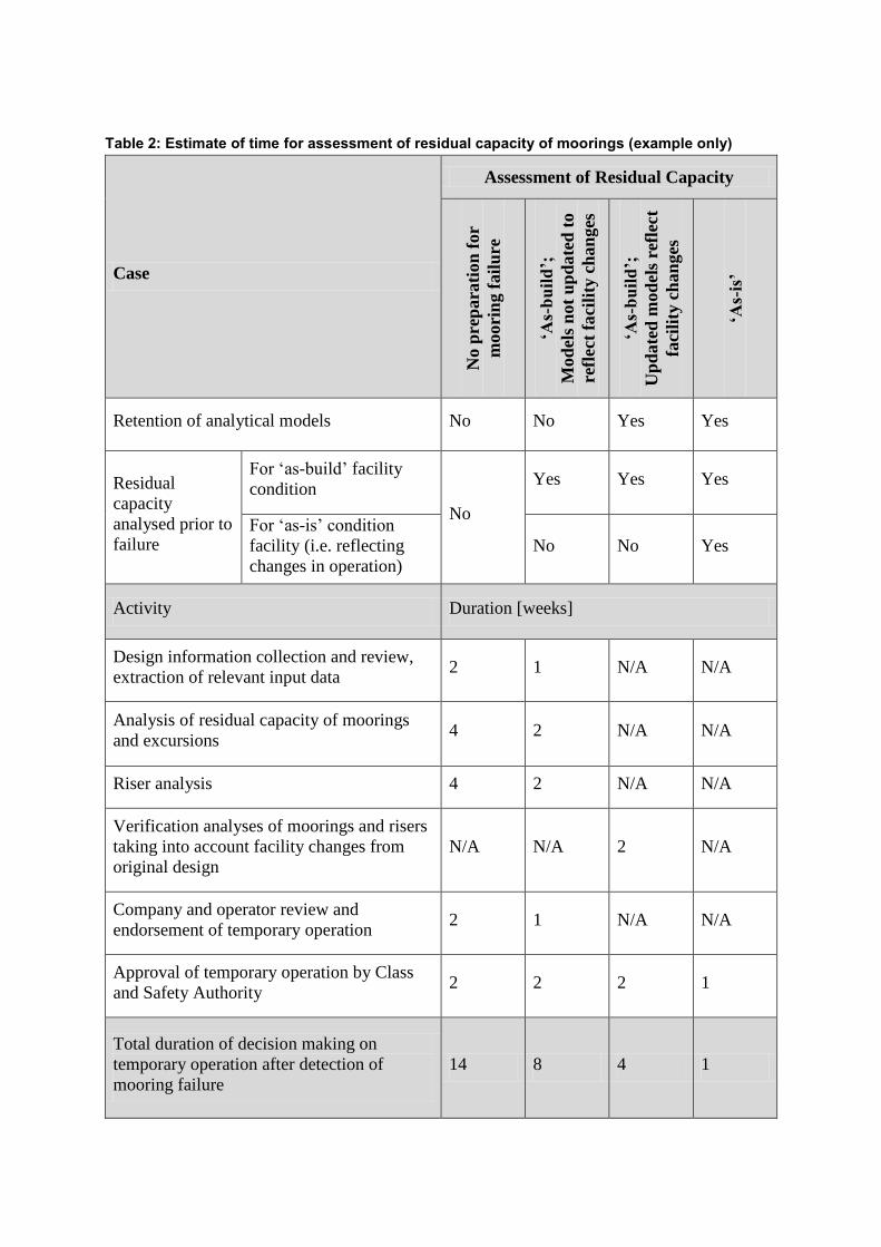
Table 2: Estimate of time for assessment of residual capacity of moorings (example only)
Case
Assessment of Residual Capacity
No p
rep
ara
tion
for
moori
ng f
ail
ure
‘As-build’;
Mod
els
not
up
date
d t
o
refl
ect
fa
cili
ty c
han
ges
‘As-build’;
Up
date
d m
od
els
refl
ect
faci
lity
ch
an
ges
‘As-is’
Retention of analytical models No No Yes Yes
Residual
capacity
analysed prior to
failure
For ‗as-build‘ facility
condition
No
Yes Yes Yes
For ‗as-is‘ condition
facility (i.e. reflecting
changes in operation)
No No Yes
Activity Duration [weeks]
Design information collection and review,
extraction of relevant input data 2 1 N/A N/A
Analysis of residual capacity of moorings
and excursions 4 2 N/A N/A
Riser analysis 4 2 N/A N/A
Verification analyses of moorings and risers
taking into account facility changes from
original design
N/A N/A 2 N/A
Company and operator review and
endorsement of temporary operation 2 1 N/A N/A
Approval of temporary operation by Class
and Safety Authority 2 2 2 1
Total duration of decision making on
temporary operation after detection of
mooring failure
14 8 4 1
3 EXAMPLE OF THE ASSESSMENT OF RESIDUAL CAPACITY OF FPSO
MOORING SYSTEM AFTER FAILURE
3.1 GENERIC DISCONNECTABLE FPSO MOORING SYSTEM
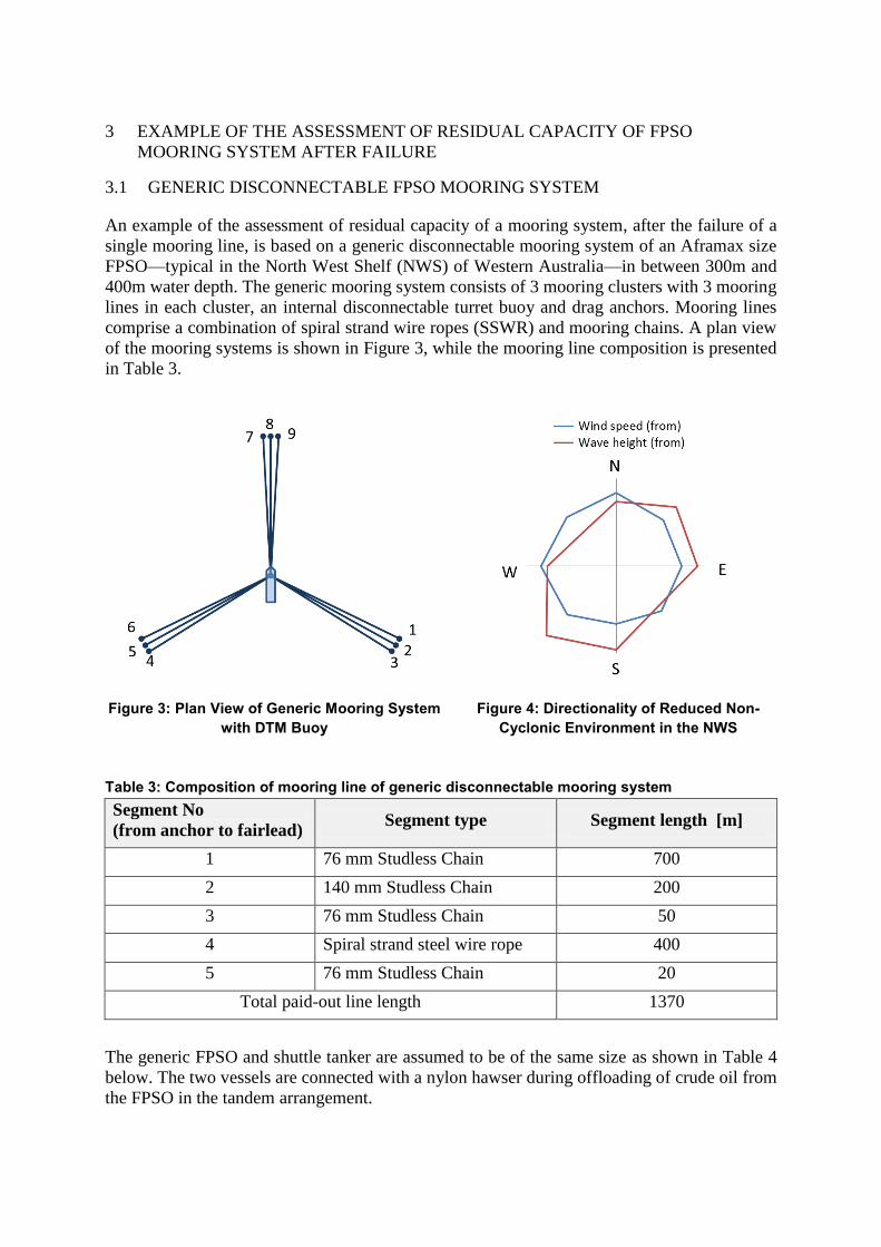
An example of the assessment of residual capacity of a mooring system, after the failure of a
single mooring line, is based on a generic disconnectable mooring system of an Aframax size
FPSO—typical in the North West Shelf (NWS) of Western Australia—in between 300m and
400m water depth. The generic mooring system consists of 3 mooring clusters with 3 mooring
lines in each cluster, an internal disconnectable turret buoy and drag anchors. Mooring lines
comprise a combination of spiral strand wire ropes (SSWR) and mooring chains. A plan view
of the mooring systems is shown in Figure 3, while the mooring line composition is presented
in Table 3.
Figure 3: Plan View of Generic Mooring System
with DTM Buoy
Figure 4: Directionality of Reduced Non-
Cyclonic Environment in the NWS
Table 3: Composition of mooring line of generic disconnectable mooring system
Segment No
(from anchor to fairlead) Segment type Segment length [m]
1 76 mm Studless Chain 700
2 140 mm Studless Chain 200
3 76 mm Studless Chain 50
4 Spiral strand steel wire rope 400
5 76 mm Studless Chain 20
Total paid-out line length 1370
The generic FPSO and shuttle tanker are assumed to be of the same size as shown in Table 4
below. The two vessels are connected with a nylon hawser during offloading of crude oil from
the FPSO in the tandem arrangement.
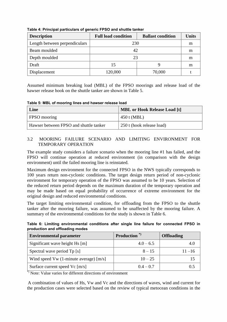
Table 4: Principal particulars of generic FPSO and shuttle tanker
Description Full load condition Ballast condition Units
Length between perpendiculars 230 m
Beam moulded 42 m
Depth moulded 23 m
Draft 15 9 m
Displacement 120,000
70,000
t
Assumed minimum breaking load (MBL) of the FPSO moorings and release load of the
hawser release hook on the shuttle tanker are shown in Table 5.
Table 5: MBL of mooring lines and hawser release load
Line MBL or Hook Release Load [t]
FPSO mooring 450 t (MBL)
Hawser between FPSO and shuttle tanker 250 t (hook release load)
3.2 MOORING FAILURE SCENARIO AND LIMITING ENVIRONMENT FOR
TEMPORARY OPERATION
The example study considers a failure scenario when the mooring line #1 has failed, and the
FPSO will continue operation at reduced environment (in comparison with the design
environment) until the failed mooring line is reinstated.
Maximum design environment for the connected FPSO in the NWS typically corresponds to
100 years return non-cyclonic conditions. The target design return period of non-cyclonic
environment for temporary operation of the FPSO was assumed to be 10 years. Selection of
the reduced return period depends on the maximum duration of the temporary operation and
may be made based on equal probability of occurrence of extreme environment for the
original design and reduced environmental conditions.
The target limiting environmental condition, for offloading from the FPSO to the shuttle
tanker after the mooring failure, was assumed to be unaffected by the mooring failure. A
summary of the environmental conditions for the study is shown in Table 6.
Table 6: Limiting environmental conditions after single line failure for connected FPSO in
production and offloading modes
Environmental parameter Production *)
Offloading
Significant wave height Hs [m] 4.0 – 6.5 4.0
Spectral wave period Tp [s] 8 – 15 11 –16
Wind speed Vw (1-minute average) [m/s] 10 – 25 15
Surface current speed Vc [m/s] 0.4 – 0.7 0.5 *)
Note: Value varies for different directions of environment
A combination of values of Hs, Vw and Vc and the directions of waves, wind and current for
the production cases were selected based on the review of typical metocean conditions in the

NWS. For the offloading cases, generic omnidirectional combinations of wind and current
directions relative to the waves were used based on the recommendations of Lloyds Register
[Ref. 11] and ABS [Ref. 12].
JONSWAP wave spectrum was used for all considered sea states, while constant velocities of
wind and current were assumed in the mooring analysis. Ranges of the wave spectral peak
period Tp covered probable contributions of swell and sea in the combined wave spectra.
About 100 base environmental cases were used for each of the connected FPSO mooring
analysis and offloading to the shuttle tanker, which covered the harshest combinations of
strength and directions of waves, wind and current.
3.3 ANALYSIS METHODOLOGY
3.3.1 Mooring Analysis Overview
Mooring analysis for the temporary operation of the FPSO after a single line failure can be
carried out in a similar way to the conventional analysis of moorings, but considering the
failed mooring system as ‗quasi-intact‘ and applying the standard mooring analysis
methodology to this ‗quasi-intact‘ system. The damage case for the ‗quasi-intact‘ mooring
system implies failure of any other mooring line in addition to the mooring line which has
already failed.
Mooring analysis for disconnectable mooring systems has to be carried for two cases:
FPSO connected to the mooring system (including offloading to shuttle tanker)
Disconnected DTM buoy
For the FPSO connected cases, an uncoupled mooring analysis in respect of the mooring
stiffness is usually sufficient due to significantly lower vertical stiffness of the catenary
mooring system in comparison with the hydrostatic stiffness of the FPSO hull. Partial
hydrodynamic coupling of the FPSO with the mooring and riser systems is achieved by
incorporating damping of the mooring lines, risers and umbilicals in the mooring analysis.
A fully coupled dynamic analysis of the FPSO, with the mooring and riser systems, may be
carried out using commercially available software, but it is more time consuming and not
mandatory. The fully coupled dynamic analysis allows application of lower factors of safety.
However, carrying out the faster quasi-dynamic mooring analysis allows consideration of a
longer time history (more wave seeds) and more environmental cases. Future progress in the
software and hardware development will likely make the fully coupled dynamic analysis a
preferred option even at early design stages.
The present example study utilises the partially coupled quasi-dynamic approach in the
mooring analysis for the connected FPSO. When the DTM buoy is disconnected from the
FPSO for tropical cyclone evasion, a fully coupled dynamic mooring analysis is required as
motions of the DTM buoy are highly dependent on dynamic loads from the mooring lines,
risers and umbilicals.
The mooring analysis in the present study has the following milestones:
Mooring analysis for connected FPSO at two loading conditions (ballasted and fully
loaded)
o Computation of response amplitude operators (RAO) of the FPSO motions and
quadratic transfer functions (QTF) of wave drift forces
o Calculation of wind and current forces and moments on the FPSO
o Calculation of additional damping due to mooring and riser systems
o Calculation of additional damping of the FPSO hull in yaw motions
o Time domain computation of the FPSO motions (at wave frequency and low
frequency) and tensions in mooring lines for the quasi-intact mooring system
o Same as the above but for damage cases
o Calculation of factors of safety for tensions in moorings and maximum
excursions of the FPSO
Mooring analysis for disconnected DTM buoy
o Time domain computation of the DTM buoy motions and tensions in mooring
lines for the quasi-intact mooring system
o Same as the above but for damage cases
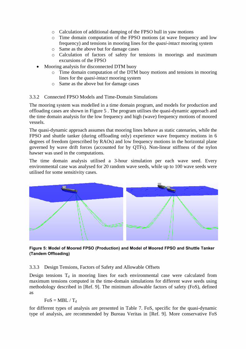
3.3.2 Connected FPSO Models and Time-Domain Simulations
The mooring system was modelled in a time domain program, and models for production and
offloading cases are shown in Figure 5 . The program utilises the quasi-dynamic approach and
the time domain analysis for the low frequency and high (wave) frequency motions of moored
vessels.
The quasi-dynamic approach assumes that mooring lines behave as static catenaries, while the
FPSO and shuttle tanker (during offloading only) experience wave frequency motions in 6
degrees of freedom (prescribed by RAOs) and low frequency motions in the horizontal plane
governed by wave drift forces (accounted for by QTFs). Non-linear stiffness of the nylon
hawser was used in the computations.
The time domain analysis utilised a 3-hour simulation per each wave seed. Every
environmental case was analysed for 20 random wave seeds, while up to 100 wave seeds were
utilised for some sensitivity cases.
Figure 5: Model of Moored FPSO (Production) and Model of Moored FPSO and Shuttle Tanker
(Tandem Offloading)
3.3.3 Design Tensions, Factors of Safety and Allowable Offsets
Design tensions Td in mooring lines for each environmental case were calculated from
maximum tensions computed in the time-domain simulations for different wave seeds using
methodology described in [Ref. 9]. The minimum allowable factors of safety (FoS), defined
as
FoS = MBL / Td
for different types of analysis are presented in Table 7. FoS, specific for the quasi-dynamic
type of analysis, are recommended by Bureau Veritas in [Ref. 9]. More conservative FoS
applicable for the quasi-static type of analysis [Ref. 4] were used for the example case.
Assumed allowable excursions of the connected FPSO for operation of risers are presented in
Table 7 as percentage of the water depth (WD).
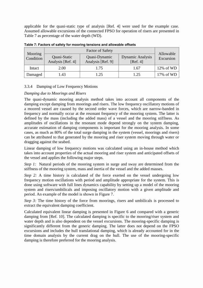
Table 7: Factors of safety for mooring tensions and allowable offsets
Mooring
Condition
Factor of Safety Allowable
Excursion Quasi-Static
Analysis [Ref. 4]
Quasi-Dynamic
Analysis [Ref. 9]
Dynamic Analysis
[Ref. 4]
Intact 2.00 1.75 1.67 12% of WD
Damaged 1.43 1.25 1.25 17% of WD
3.3.4 Damping of Low Frequency Motions
Damping due to Moorings and Risers
The quasi-dynamic mooring analysis method takes into account all components of the
damping except damping from moorings and risers. The low frequency oscillatory motions of
a moored vessel are caused by the second order wave forces, which are narrow-banded in
frequency and normally occur at the resonant frequency of the mooring system. The latter is
defined by the mass (including the added mass) of a vessel and the mooring stiffness. As
amplitudes of oscillations in the resonant mode depend strongly on the system damping,
accurate estimation of damping components is important for the mooring analysis. In some
cases, as much as 80% of the total surge damping in the system (vessel, moorings and risers)
can be attributed to that generated by the mooring and riser system moving through water or
dragging against the seabed.
Linear damping of low frequency motions was calculated using an in-house method which
takes into account properties of the actual mooring and riser system and anticipated offsets of
the vessel and applies the following major steps.
Step 1: Natural periods of the mooring system in surge and sway are determined from the
stiffness of the mooring system, mass and inertia of the vessel and the added masses.
Step 2: A time history is calculated of the force exerted on the vessel undergoing low
frequency motion oscillations with period and amplitude appropriate for the system. This is
done using software with full lines dynamics capability by setting up a model of the mooring
system and risers/umbilicals and imposing oscillatory motion with a given amplitude and
period. An example of the model is shown in Figure 7.
Step 3: The time history of the force from moorings, risers and umbilicals is processed to
extract the equivalent damping coefficient.
Calculated equivalent linear damping is presented in Figure 6 and compared with a generic
damping from [Ref. 10]. The calculated damping is specific to the mooring/riser system and
water depth and is also dependent on the vessel excursions. The mooring-specific damping is
significantly different from the generic damping. The latter does not depend on the FPSO
excursions and includes the hull translational damping, which is already accounted for in the
time domain analysis by the current drag on the hull. The use of the mooring-specific
damping is therefore preferred for the mooring analysis.

Figure 6: Linear Damping due to Moorings
and Risers
Figure 7: Model of Moorings, Risers and
Umbilical for Determination of Equivalent
Linear Damping
Calculation of damping, specific to some governing environmental cases, was made by
iterations, using an estimate of the vessel excursions from previous time domain simulation
and case-specific current speed and condition of the mooring system (intact or damaged
lines).
Hull Yaw Damping
An approximate value for yaw damping, associated with the viscous drag on the vessel hull,
can be automatically calculated by some software packages using input provided by the user
(e.g. the transverse current drag coefficient). The present study utilises liner yaw damping
calculated as:
NL BaB 3
8
where:
TLBN
40125.0 – nonlinear damping; L – hull length; T – hull draft; – circular
frequency of yaw motions; a – amplitude of yaw motions.
This formula for BN applies a typical distribution of the transverse drag along the hull and
effect of the Keulegan-Carpenter (KC) number due to periodic oscillatory yaw motions.
3.3.5 Analysis for Disconnected DTM Buoy
Checking the residual capacity of the mooring system and riser survivability is mandatory for
the DTM disconnected case – similar to the connected case. This analysis is executed for
reduced cyclonic conditions due to the temporary operation of the mooring system until its
repair. Previous experience shows that the DTM disconnected cases are usually less critical
than the FPSO connected cases, and they are not presented in this paper.
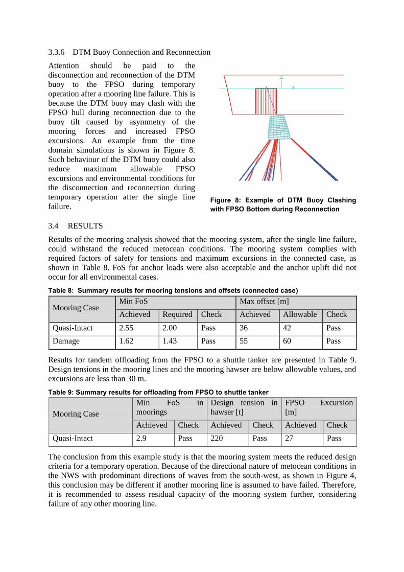
3.3.6 DTM Buoy Connection and Reconnection
Attention should be paid to the
disconnection and reconnection of the DTM
buoy to the FPSO during temporary
operation after a mooring line failure. This is
because the DTM buoy may clash with the
FPSO hull during reconnection due to the
buoy tilt caused by asymmetry of the
mooring forces and increased FPSO
excursions. An example from the time
domain simulations is shown in Figure 8.
Such behaviour of the DTM buoy could also
reduce maximum allowable FPSO
excursions and environmental conditions for
the disconnection and reconnection during
temporary operation after the single line
failure.
Figure 8: Example of DTM Buoy Clashing
with FPSO Bottom during Reconnection
3.4 RESULTS
Results of the mooring analysis showed that the mooring system, after the single line failure,
could withstand the reduced metocean conditions. The mooring system complies with
required factors of safety for tensions and maximum excursions in the connected case, as
shown in Table 8. FoS for anchor loads were also acceptable and the anchor uplift did not
occur for all environmental cases.
Table 8: Summary results for mooring tensions and offsets (connected case)
Mooring Case Min FoS Max offset [m]
Achieved Required Check Achieved Allowable Check
Quasi-Intact 2.55 2.00 Pass 36 42 Pass
Damage 1.62 1.43 Pass 55 60 Pass
Results for tandem offloading from the FPSO to a shuttle tanker are presented in Table 9.
Design tensions in the mooring lines and the mooring hawser are below allowable values, and
excursions are less than 30 m.
Table 9: Summary results for offloading from FPSO to shuttle tanker
Mooring Case
Min FoS in
moorings
Design tension in
hawser [t]
FPSO Excursion
[m]
Achieved Check Achieved Check Achieved Check
Quasi-Intact 2.9 Pass 220 Pass 27 Pass
The conclusion from this example study is that the mooring system meets the reduced design
criteria for a temporary operation. Because of the directional nature of metocean conditions in
the NWS with predominant directions of waves from the south-west, as shown in Figure 4,
this conclusion may be different if another mooring line is assumed to have failed. Therefore,
it is recommended to assess residual capacity of the mooring system further, considering
failure of any other mooring line.
As an alternative assessment method, the response based analysis of the mooring system,
using a site-specific metocean time history for several years, can be carried for the
identification of most critical cases and determination of maximum tensions and excursions
corresponding to a given return period.
4 EXAMPLE OF DEEP WATER MOORING REPLACEMENT PROCEDURE
4.1 GENERIC DEEP WATER SPREAD MOORING SYSTEM AND FAILURE &
REPLACEMENT SCENARIOS
A generic mooring system for an FPSO in 1000 m water depth comprises four clusters with
three mooring lines in each cluster. The mooring lines are connected to suction pile anchors
on the seabed and chain stoppers on the FPSO deck. Mooring lines consist of a short length of
ground chain, a long spiral strand wire rope (SSWR) with polyethylene sheath and a short
section of top chain where the paid-out length can be adjusted. The mooring line composition
is shown in Table 10.
Table 10: Mooring leg composition of generic deep water spread mooring system
Item
#
Mooring component
(from anchor) Description
1 Suction pile anchor Length: 22m; Diameter: 5m; Mass: 150 tonnes
2 Ground chain 130m of 110mm chain
3 Spiral strand wire rope
(SSWR)
1450m of sheathed spiral strand wire (102mm strand diameter);
closed spelter sockets on each end
4 Top chain 100m of 110mm chain
5 Shackles Shackles connecting: suction pile padeye to ground chain; ground
chain to SSWR; SSWR to top chain
Failure of any of the mooring
components in Table 10 may results in a
complete failure of a single mooring leg.
Defects of the mooring components
revealed by inspections may also require
immediate action for repair or
replacement.
Replacement of the entire mooring leg
may be considered as preferred option
after mooring failure for reducing the
mooring reinstatement time. A new
suction pile has to be installed at some
distance (20-30m) from the existing pile
closer to the FPSO to avoid any reduction
of the soil holding properties and
interference of the replaced ground chain
with the abandoned suction pile. The
mooring leg replacement procedure is
described below.
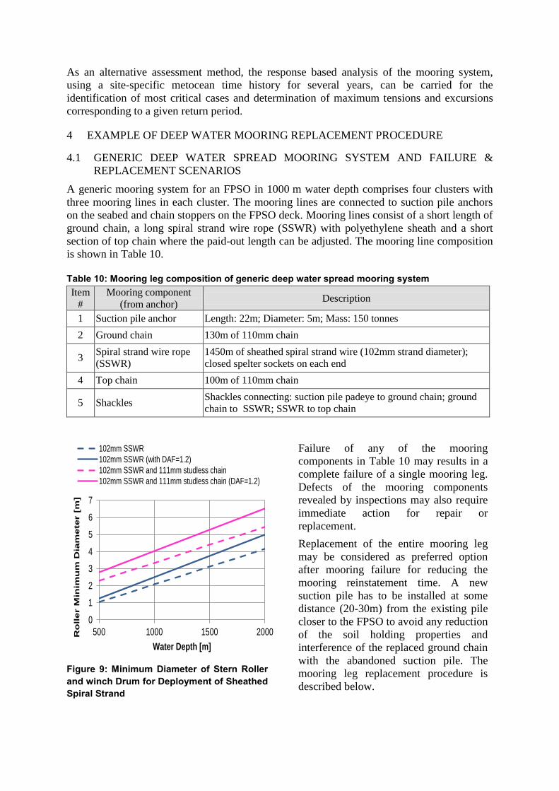
Figure 9: Minimum Diameter of Stern Roller
and winch Drum for Deployment of Sheathed
Spiral Strand
0
1
2
3
4
5
6
7
500 1000 1500 2000Ro
ller M
inim
um
Dia
me
ter [
m]
Water Depth [m]
102mm SSWR
102mm SSWR (with DAF=1.2)
102mm SSWR and 111mm studless chain
102mm SSWR and 111mm studless chain (DAF=1.2)

4.2 GENERIC MOORING REPLACEMENT METHODOLOGY
Requirements for installation of sheathed SSWR
Polyethylene sheath on SSWR is used in many deep water moorings as it significantly
reduces corrosion of the steel strand and allows its prolonged operation without deterioration
of SSWR mechanical properties for a period of up to 25 years. The sheath is prone to damage
during handling and installation, and imposes certain limitations for the installation methods
and equipment. Pressure on the sheath has to be limited during installation to prevent its
collapse or plastic deformation. This implies limits on allowable tension in SSWR and also
consequential limits for caterpillar-type tensioners, winches and stern rollers. A generic
formula below [Ref. 3] gives the minimum diameter of the winch drum or stern roller against
tension in sheathed SSWR.
where:
D = diameter of deployment stern roller or flat drum (mm)
W = line load (N)
b = allowable average bearing pressure on the sheath (21 N/mm2)
d = nominal sheath outside diameter (mm)
t = nominal sheath wall thickness (mm)
As illustrated in Figure 9, the limiting water depth for deployment of sheathed SSWR and
ground chain using a winch and stern roller with diameters typical for offshore support
vessels (OSV) and anchor handling tugs (AHT) is about 1000 m, while suspension of the
ground chain weight by a wire from the installation vessel may extend this limit to
approximately 1500 m.
Provision of a sheath repair and spiral strand re-termination kits on-board an OSV is
recommended for the prompt repair of SSWR in case of its damage during installation.
Marine Spread Selection
A preferred option, for the replacement of a single mooring leg after failure, is the use of
available support vessels in the area rather than the mobilisation of a large crane barge similar
to that probably used for the original installation of 12 mooring legs before the FPSO hook-
up. The ―use what is available‖ principle may bring challenges in the development of the
mooring replacement procedures, which could be overcome via detailed engineering work
involving dynamic analysis. As a minimum requirement an OSV with DP system, hull length
between 80 m and 100 m, SSWR winch, stern roller and deck crane (about 100 tonnes
capacity) may be sufficient for the installation of the new suction pile with mooring line in the
present example.
Suction Pile Overboarding
Overboarding the suction pile using a deck crane with sufficient capacity (about 300 tonnes in
the example case) may increase mobilisation time and cost for the installation vessel, so the
use of the stern roller on the selected smaller OSV is likely to be a less expensive and a faster
option. A risk of the suction pile top clashing with the OSV roller or hull during overboarding
using a lowering work wire at the pile centreline needs to be closely reviewed and may be
mitigated by attaching an additional work wire to the pile side. This technique was verified in
the installation analysis as shown in Figure 10, where the pile top is tilted away from the stern
roller.
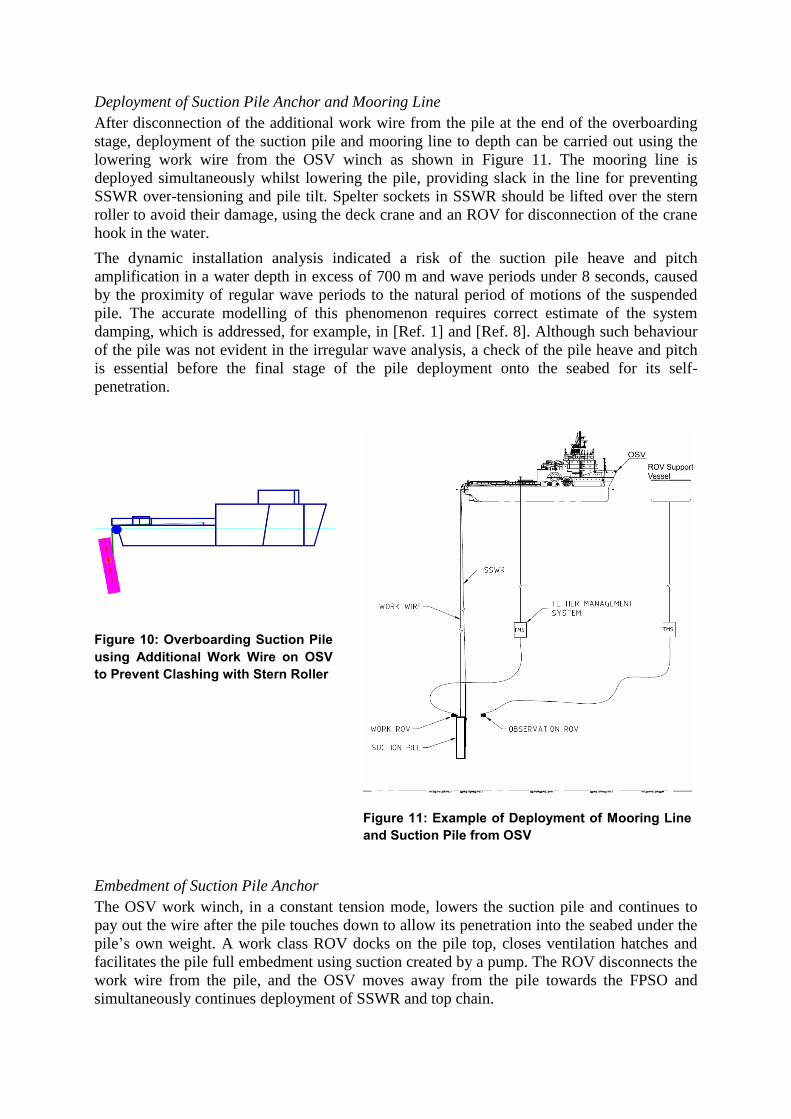
Deployment of Suction Pile Anchor and Mooring Line
After disconnection of the additional work wire from the pile at the end of the overboarding
stage, deployment of the suction pile and mooring line to depth can be carried out using the
lowering work wire from the OSV winch as shown in Figure 11. The mooring line is
deployed simultaneously whilst lowering the pile, providing slack in the line for preventing
SSWR over-tensioning and pile tilt. Spelter sockets in SSWR should be lifted over the stern
roller to avoid their damage, using the deck crane and an ROV for disconnection of the crane
hook in the water.
The dynamic installation analysis indicated a risk of the suction pile heave and pitch
amplification in a water depth in excess of 700 m and wave periods under 8 seconds, caused
by the proximity of regular wave periods to the natural period of motions of the suspended
pile. The accurate modelling of this phenomenon requires correct estimate of the system
damping, which is addressed, for example, in [Ref. 1] and [Ref. 8]. Although such behaviour
of the pile was not evident in the irregular wave analysis, a check of the pile heave and pitch
is essential before the final stage of the pile deployment onto the seabed for its self-
penetration.
Figure 10: Overboarding Suction Pile
using Additional Work Wire on OSV
to Prevent Clashing with Stern Roller
Figure 11: Example of Deployment of Mooring Line
and Suction Pile from OSV
Embedment of Suction Pile Anchor
The OSV work winch, in a constant tension mode, lowers the suction pile and continues to
pay out the wire after the pile touches down to allow its penetration into the seabed under the
pile‘s own weight. A work class ROV docks on the pile top, closes ventilation hatches and
facilitates the pile full embedment using suction created by a pump. The ROV disconnects the
work wire from the pile, and the OSV moves away from the pile towards the FPSO and
simultaneously continues deployment of SSWR and top chain.
5 CONCLUSIONS
The development of a Mooring Integrity Management Plan (MIMP) facilitates early detection
of a mooring anomaly, may allow temporary operation of the FPSO after a mooring line
failure, and accelerate the mooring repair or replacement campaign, thus reducing or
eliminating production loss caused by the mooring anomaly. Development of an MIMP in
the beginning of the FPSO operation or even before its commissioning is recommended as
experience shows many mooring failures occur at early operation stages. The costs of lost
production in the early production stages are higher than in the later years, therefore the
importance of minimising any downtime is critical.
Retention of analytical models is important for the prompt verification and update of the
Mooring Failure Rapid Response Plan (MFRRP) in case of deviation of the FPSO, mooring
and riser systems and available marine spread from those initially assumed. Specifications for
spare mooring components, assessment of residual capacity of the mooring system after its
partial failure and mooring removal and installation procedures should be maintained up to
date to reflect actual operating conditions.
A possibility exists for operation of an FPSO in the North West Shelf of Australia after a
single line failure for up to several months at reduced design environmental conditions –
subject to the mooring and riser systems design, orientation of the failed line relative to the
predominant environment and necessary approvals. This possibility has to be established by
the assessment of residual capacity of the mooring, considering the mooring system after the
line failure as in ‗quasi-intact‘ condition and applying the advanced analysis methodology.
Replacement of a mooring leg in deep water, using available support vessels, imposes
additional challenges and potential risks which should be understood and addressed. The
replacement procedures require dynamic analysis and development of additional protection
measures for sensitive mooring components from damage during retrieval and installation.
6 REFERENCES
[Ref. 1] J. Ireland, G. Macfarlane, Y. Drobyshevski, ―Investigation into the sensitivity of
the dynamic hook load during subsea deployment of suction can‖, OMAE2007-
29244, Proceedings of OMAE2007, San Diego USA, June 2007.
[Ref. 2] F.J. McMaster, J.A. Abadin, C.J. Waldhart, Y.D. Lee, S. Das, Bill Greiner, ―Fit-
for-Service Assessment of Deepwater In-Service Low Toughness Mooring
Shackles‖, Document ID 20624-MS, Proceedings of OTC-2010, Houston, Texas,
USA, May 2010.
[Ref. 3] S.L. Sefton, K. Firth, S. Hallam, ―Installation and Handling of Steel Permanent
Mooring Cables‖, http://www.offshore-mag.com/articles/.
[Ref. 4] API, ―Design and analysis of station keeping systems for floating structures‖,
Recommended Practice 2SK, 3rd
Edition, October 2005.
[Ref. 5] API, ―In-service Inspection of Mooring Hardware for Floating Structures‖,
Recommended Practice 2I, 3rd
Edition, April 2008.
[Ref. 6] API, ―Risk-based Inspection‖, Recommended Practice 580, 1st Edition, 2002.
[Ref. 7] API, ―Risk-based Inspection: Base Resource Document‖, Recommended Practice
581, 1st Edition, 2000.
[Ref. 8] DNV, ―Modelling and Analysis of Marine Operations‖, Recommended Practice
H103, April 2011.
[Ref. 9] Bureau Veritas, ―Classification of Mooring Systems for Permanent Offshore
Units‖, Guidance Note NI 493 DTM R01 E, July 2008.
[Ref. 10] Bureau Veritas, ―Quasi-dynamic Analysis of Mooring Systems Using ARIANE
Software‖, Guidance Note NI 461, 1998.
[Ref. 11] Lloyd‘s Register, ―Rules and Regulations for the Classification of a Floating
Offshore Installation at a Fixed Location‖, April 2008.
[Ref. 12] ABS, ―Floating Production Installations‖, Guide for Building and Classing, July
2009.
[Ref. 13] Noble Denton Europe Limited, ―Floating Production System: JIP FPS Mooring
Integrity‖, Prepared for the Health and Safety Executive, Research report 444,
2006, http://www.hse.gov.uk/research/.
[Ref. 14] Upstream News, ―Petrobras Sues over Chains in GOM Project‖,
http://www.upstreamonline.com/live/article1243028.ece.
[Ref. 15] U.S. Department of the Interior: Bureau of Ocean Energy Management,
Regulation and Enforcement, ―Gulf of Mexico OCS Region Catastrophic Failures
in Mooring Systems Possibly Put Floating Structures at Risk‖, Safety Alert No.
296, 12 May 2011.
Related Documents