Maine DOT Hydraulic Capacity Standard & Guidance Culverts proposed under this program must satisfy the hydraulic sizing standard, that at the 100-year flow Q100, the water is no deeper than “just full” or “100% full” at the inlet. The water at the inlet is called the “headwater” Hw. This condition is expressed as the “headwater depth ratio” Hw/Ro where Ro is the height of the opening through which water flows: Hw/Ro <= 1 @ Q100 At large flows such as Q100, the water is generally deeper at the inlet than inside the culvert. For simple round pipes without streambed, this is the familiar Headwater-Diameter ratio “Hw/D”, where D is the diameter. Figure 1. Culvert flowing “just full” or “100% full” at the inlet Sizing according to bankfull width (BFW) (BFW or 1.2 x BFW) almost always results in headwater depths Hw less than “just full” (Hw/Ro < 1) and thus hydraulic capacity generally is not an issue. However, it is important to check the capacity, for two reasons: 1. To catch those rare instances where capacity might be an issue 2. To avoid oversizing structures by simply “making things bigger, just to be safe” MaineDOT sizes large culvert structures (span S or diameter D >= 5’) according to this hydraulic standard Hw/Ro <= 1, in addition to meeting any other applicable requirements. Hw ds R Ro Hw/Ro = 1 R = Ro + ds Water Surface Inlet Outlet

Welcome message from author
This document is posted to help you gain knowledge. Please leave a comment to let me know what you think about it! Share it to your friends and learn new things together.
Transcript
Maine DOT Hydraulic Capacity Standard & Guidance
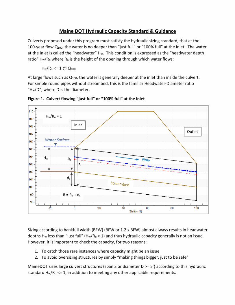
Culverts proposed under this program must satisfy the hydraulic sizing standard, that at the 100-year flow Q100, the water is no deeper than “just full” or “100% full” at the inlet. The water at the inlet is called the “headwater” Hw. This condition is expressed as the “headwater depth ratio” Hw/Ro where Ro is the height of the opening through which water flows:
Hw/Ro <= 1 @ Q100
At large flows such as Q100, the water is generally deeper at the inlet than inside the culvert. For simple round pipes without streambed, this is the familiar Headwater-Diameter ratio “Hw/D”, where D is the diameter.
Figure 1. Culvert flowing “just full” or “100% full” at the inlet
Sizing according to bankfull width (BFW) (BFW or 1.2 x BFW) almost always results in headwater depths Hw less than “just full” (Hw/Ro < 1) and thus hydraulic capacity generally is not an issue. However, it is important to check the capacity, for two reasons:
1. To catch those rare instances where capacity might be an issue 2. To avoid oversizing structures by simply “making things bigger, just to be safe”
MaineDOT sizes large culvert structures (span S or diameter D >= 5’) according to this hydraulic standard Hw/Ro <= 1, in addition to meeting any other applicable requirements.
Hw
ds
R Ro
Hw/Ro = 1
R = Ro + ds
Water Surface
Inlet Outlet
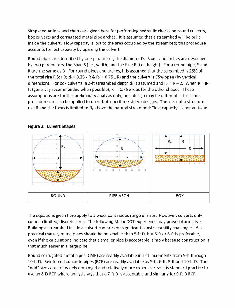
Simple equations and charts are given here for performing hydraulic checks on round culverts, box culverts and corrugated metal pipe arches. It is assumed that a streambed will be built inside the culvert. Flow capacity is lost to the area occupied by the streambed; this procedure accounts for lost capacity by upsizing the culvert.
Round pipes are described by one parameter, the diameter D. Boxes and arches are described by two parameters, the Span S (i.e., width) and the Rise R (i.e., height). For a round pipe, S and R are the same as D. For round pipes and arches, it is assumed that the streambed is 25% of the total rise R (or D; ds = 0.25 x R & Ro = 0.75 x R) and the culvert is 75% open (by vertical dimension). For box culverts, a 2-ft streambed depth ds is assumed and Ro = R – 2. When R = 8-ft (generally recommended when possible), Ro = 0.75 x R as for the other shapes. These assumptions are for this preliminary analysis only; final design may be different. This same procedure can also be applied to open-bottom (three-sided) designs. There is not a structure rise R and the focus is limited to Ro above the natural streambed; “lost capacity” is not an issue.
Figure 2. Culvert Shapes
ROUND PIPE ARCH BOX
The equations given here apply to a wide, continuous range of sizes. However, culverts only come in limited, discrete sizes. The following MaineDOT experience may prove informative. Building a streambed inside a culvert can present significant constructability challenges. As a practical matter, round pipes should be no smaller than 5-ft D, but 6-ft or 8-ft is preferable, even if the calculations indicate that a smaller pipe is acceptable, simply because construction is that much easier in a large pipe.
Round corrugated metal pipes (CMP) are readily available in 1-ft increments from 5-ft through 10-ft D. Reinforced concrete pipes (RCP) are readily available as 5-ft, 6-ft, 8-ft and 10-ft D. The “odd” sizes are not widely employed and relatively more expensive, so it is standard practice to use an 8-D RCP where analysis says that a 7-ft D is acceptable and similarly for 9-ft D RCP.
D
R
S
R
S Ro
ds
Ro

MaineDOT usually employs concrete box culverts once diameters or stream widths greater than 8-ft are encountered. RCP commonly comes in 8-ft section lengths. CMP commonly come in 20-ft or 10-ft sections; the sections can be cut to individual lengths as needed.
Smaller concrete boxes commonly come in 8-ft section lengths, 2-ft increments for span S and 1-ft increments for rise R. Larger boxes may come in smaller section lengths due to weight constraints; they may also come as “clamshells”, with a top half and bottom half. Clamshells make it easier to build the streambed, since the gravel and rock can simply be dropped into the open culvert before the top half is set. However, this advantage can be offset by the additional labor and machine time needed to set twice as many pieces.
Corrugated metal pipe arches (CMPA) are specified in inches; commonly available sizes for 3” x 1” corrugations are given in Table 1 below. CMPA’s are particularly useful when road cover over the culvert is a limitation and they are also usually less expensive than the corresponding concrete box culvert when round pipes cannot be used.
As noted above, it is almost always the case that sizing for BFW will automatically satisfy the Q100 hydraulic standard. This is especially true of round pipes and CMPA’s, since the span S (usually determined by BFW) automatically determines the rise R:
Round: D = S = R
Arch: R = 1.15 x S0.76 (R & S in ft) = 2.08 x S0.76 (R & S in inches)
However, the box culvert rise R is set independently of the span (width) S. It is recommended that the box culvert open rise Ro (above the streambed) be at least 6-ft, for reasons of constructability and maintenance; Ro = 4’ is the minimum acceptable. Streambed depth ds is added to Ro to get the structure rise R:
R = Ro + ds
For a streambed depth of 2-ft, this gives a structure rise of 6-ft minimum with 8-ft preferred. Greater streambed depths ds will result in larger structure rises R.
The procedures for checking hydraulic capacity given here are for feasibility and preliminary design only. For each pipe shape, two methods are given: calculation and graphical look-up. The user should use both methods and verify that the same results are obtained by both methods. Only those shapes under consideration need be analyzed; this may be just one, two or all three shapes.
The final design should be checked again for hydraulic performance by a Professional Engineer as part of the project design. Simplifying assumptions used here (streambed depth, inlet control) may not apply to the final design. Also, the elevation of the road surface above the streambed may limit the structure rise that can be achieved; the desired culvert may not “fit”. A conservative rule of thumb is that 2 – 3-ft is required from pavement surface to top of culvert. This should be checked even at this preliminary stage.
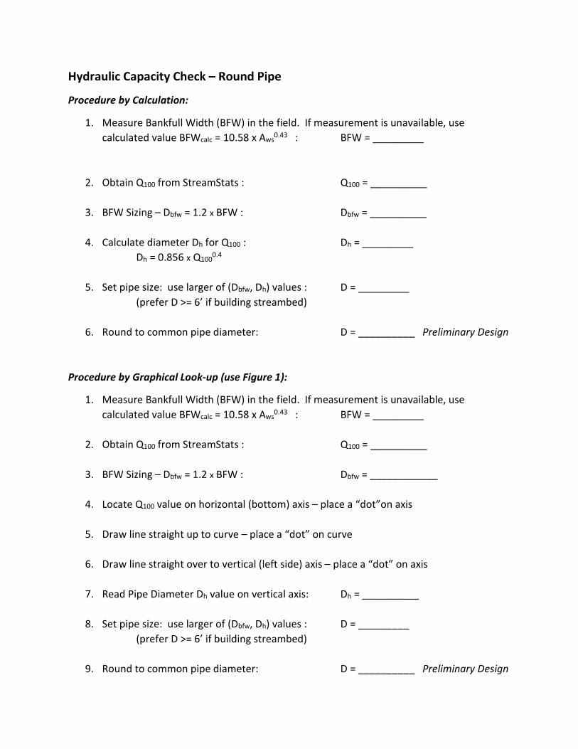
Hydraulic Capacity Check – Round Pipe
Procedure by Calculation:
1. Measure Bankfull Width (BFW) in the field. If measurement is unavailable, use calculated value BFWcalc = 10.58 x Aws0.43 : BFW = _________
2. Obtain Q100 from StreamStats : Q100 = __________
3. BFW Sizing – Dbfw = 1.2 x BFW : Dbfw = __________
4. Calculate diameter Dh for Q100 : Dh = _________ Dh = 0.856 x Q1000.4
5. Set pipe size: use larger of (Dbfw, Dh) values : D = _________
(prefer D >= 6’ if building streambed)
6. Round to common pipe diameter: D = __________ Preliminary Design
Procedure by Graphical Look-up (use Figure 1):
1. Measure Bankfull Width (BFW) in the field. If measurement is unavailable, use calculated value BFWcalc = 10.58 x Aws0.43 : BFW = _________
2. Obtain Q100 from StreamStats : Q100 = __________
3. BFW Sizing – Dbfw = 1.2 x BFW : Dbfw = ____________
4. Locate Q100 value on horizontal (bottom) axis – place a “dot”on axis
5. Draw line straight up to curve – place a “dot” on curve
6. Draw line straight over to vertical (left side) axis – place a “dot” on axis
7. Read Pipe Diameter Dh value on vertical axis: Dh = __________
8. Set pipe size: use larger of (Dbfw, Dh) values : D = _________ (prefer D >= 6’ if building streambed)
9. Round to common pipe diameter: D = __________ Preliminary Design
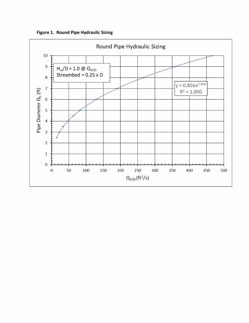
Figure 1. Round Pipe Hydraulic Sizing
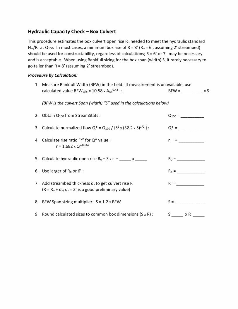
Hydraulic Capacity Check – Box Culvert
This procedure estimates the box culvert open rise Ro needed to meet the hydraulic standard Hw/Ro at Q100. In most cases, a minimum box rise of R = 8’ (Ro = 6’, assuming 2’ streambed) should be used for constructability, regardless of calculations; R = 6’ or 7’ may be necessary and is acceptable. When using Bankfull sizing for the box span (width) S, it rarely necessary to go taller than R = 8’ (assuming 2’ streambed).
Procedure by Calculation:
1. Measure Bankfull Width (BFW) in the field. If measurement is unavailable, use calculated value BFWcalc = 10.58 x Aws0.43 : BFW = _________ = S (BFW is the culvert Span (width) “S” used in the calculations below)
2. Obtain Q100 from StreamStats : Q100 = __________
3. Calculate normalized flow Q* = Q100 / {S2 x (32.2 x S)1/2 } : Q* = ___________
4. Calculate rise ratio “r” for Q* value : r = ___________ r = 1.682 x Q*0.667
5. Calculate hydraulic open rise Ro = S x r = _____ x _____ Ro = ____________
6. Use larger of Ro or 6’ : Ro = ____________
7. Add streambed thickness ds to get culvert rise R R = ____________
(R = Ro + ds; ds = 2’ is a good preliminary value)
8. BFW Span sizing multiplier: S = 1.2 x BFW S = _____________
9. Round calculated sizes to common box dimensions (S x R) : S _____ x R _____

Procedure by Graphical Look-Up (Use Figure 2):
1. Measure Bankfull Width (BFW) in the field. If measurement is unavailable, use calculated value BFWcalc = 10.58 x Aws0.43 : BFW = _________ = S (BFW is the culvert Span (width) “S” used in the calculations below)
2. Obtain Q100 from StreamStats : Q100 = __________
3. Locate Q100 on vertical (left) axis of top graph – place a “dot” on axis
4. Draw horizontal line from “dot” to line corresponding to initial Span S value (estimate position between lines for odd-value span)
5. Draw a vertical line down, through horizontal axis (Q*) into next graph and stop where it hits curve – place a “dot” on curve
6. Draw horizontal line from “dot” to vertical axis (r) – place a “dot”
7. Record “r” value on vertical axis: r = __________
8. Calculate hydraulic open rise Ro : Ro = S x r = _____ x _____ Ro = _________
9. Use larger of Ro or 6’ : Ro = ____________
10. Add streambed thickness ds to get culvert rise R R = ____________ (R = Ro + ds; ds = 2’ is a good preliminary value)
11. BFW Span sizing multiplier: S = 1.2 x BFW S = _____________
12. Round calculated sizes to common box dimensions (S x R) : _____ x _____
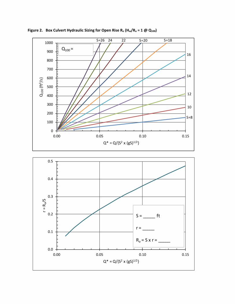
Figure 2. Box Culvert Hydraulic Sizing for Open Rise Ro (Hw/Ro = 1 @ Q100)
0
100
200
300
400
500
600
700
800
900
1000
0.00 0.05 0.10 0.15
Q10
0(ft
3 /s)
Q* = Q/{S2 x (gS)1/2}
0.0
0.1
0.2
0.3
0.4
0.5
0.00 0.05 0.10 0.15
r = R
o/S
Q* = Q/{S2 x (gS)1/2}
S=8
10
12
14
16
S=18S=2022S=26 24
S = _____ ft
r = _____
Ro = S x r = _____
Q100 =

Hydraulic Capacity Check – Corrugated Metal Pipe Arch
This procedure estimates the CMPA open rise Ro needed to meet the hydraulic standard Hw/Ro at Q100 . The streambed ds is assumed to be 25% of the arch rise R; Ro is 75% of R.
Procedure by Calculation:
1. Measure Bankfull Width (BFW) in the field. If measurement is unavailable, use calculated value BFWcalc = 10.58 x Aws0.43 : BFW = _________ (BFW is the culvert Span (width) “S” used in the calculations below)
2. Obtain Q100 from StreamStats : Q100 = __________
3. BFW Span sizing: Sbfw = 1.2 x BFW Sbfw (ft) = __________
4. Calculate hydraulic sizing Arch Span Sh (ft) for Q100 : Sh (ft) = ___________ S = 0.708 x Q0.473
5. Choose larger of Sh & Sbfw : S (ft) = __________
6. Convert S to inches ( x 12) : S (in) = __________
7. Round S to nearest available arch span (Table 1);
record dimensions in (inches): S _____ x R ______
Table 1. Commonly Available Pipe Arch Sizes (3” x 1” corrugation)
Span (in) Rise (in) End Area (ft2) Span (in) Rise (in) End Area (ft2) 60 46 15.6 103 71 42.4 66 51 19.3 112 75 48.0 73 55 23.2 117 79 54.2 81 59 27.4 128 83 60.5 87 63 32.1 137 87 67.4 95 67 37.0 142 91 74.5

Procedure by Graphical Look-Up (Use Figure 3):
1. Measure Bankfull Width (BFW) in the field. If measurement is unavailable, use calculated value BFWcalc = 10.58 x Aws0.43 : BFW = _________ (BFW is the culvert Span (width) “S” used in the calculations below)
2. Obtain Q100 from StreamStats : Q100 = __________
3. BFW Span sizing: Sbfw = 1.2 x BFW Sbfw = __________
4. Locate Q100 on horizontal axis – mark a “dot”
5. Draw vertical line up from dot to curve – mark a “dot”
6. Draw horizontal line over to vertical axis – mark a “dot”
7. Record pipe arch hydraulic sizing Span Sh: Sh (ft) = ________
8. Choose larger of Sh & Sbfw : S (ft) = ________
9. Convert S to inches ( x 12) : S (in) = __________
10. Round S to nearest available arch span (Table 1);
record dimensions in (inches): S _____ x R ______
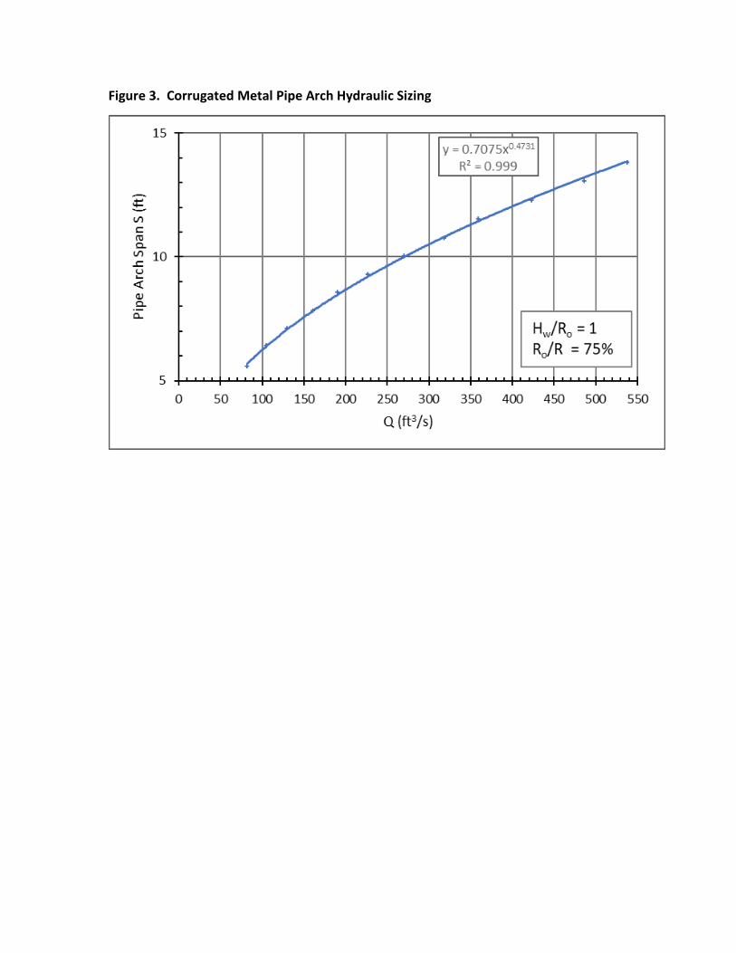
Figure 3. Corrugated Metal Pipe Arch Hydraulic Sizing

Example – Round Pipe Sizing (assuming streambed ds = 0.25 x D)
From StreamStats: Aws = 0.25 mi2 & NWI = 3%
1. BFW = 6’
2. StreamStats: Q100 = 70 ft3/s
3. Calculate BFW Sizing: Dbfw = 1.2 x BFW = 7.2’
4. Hydraulic sizing: a. Calculate Dh = 0.856 x (70)0.4 = 4.7 ft b. Look up hydraulic sizing from chart: Dh = 4.7’ from chart
5. Use larger of Dbfw or Dh: max (7.2, 4.7) = 7.2’
6. Round to common pipe size: D = 7’D preliminary design
7. Check that this fits under road
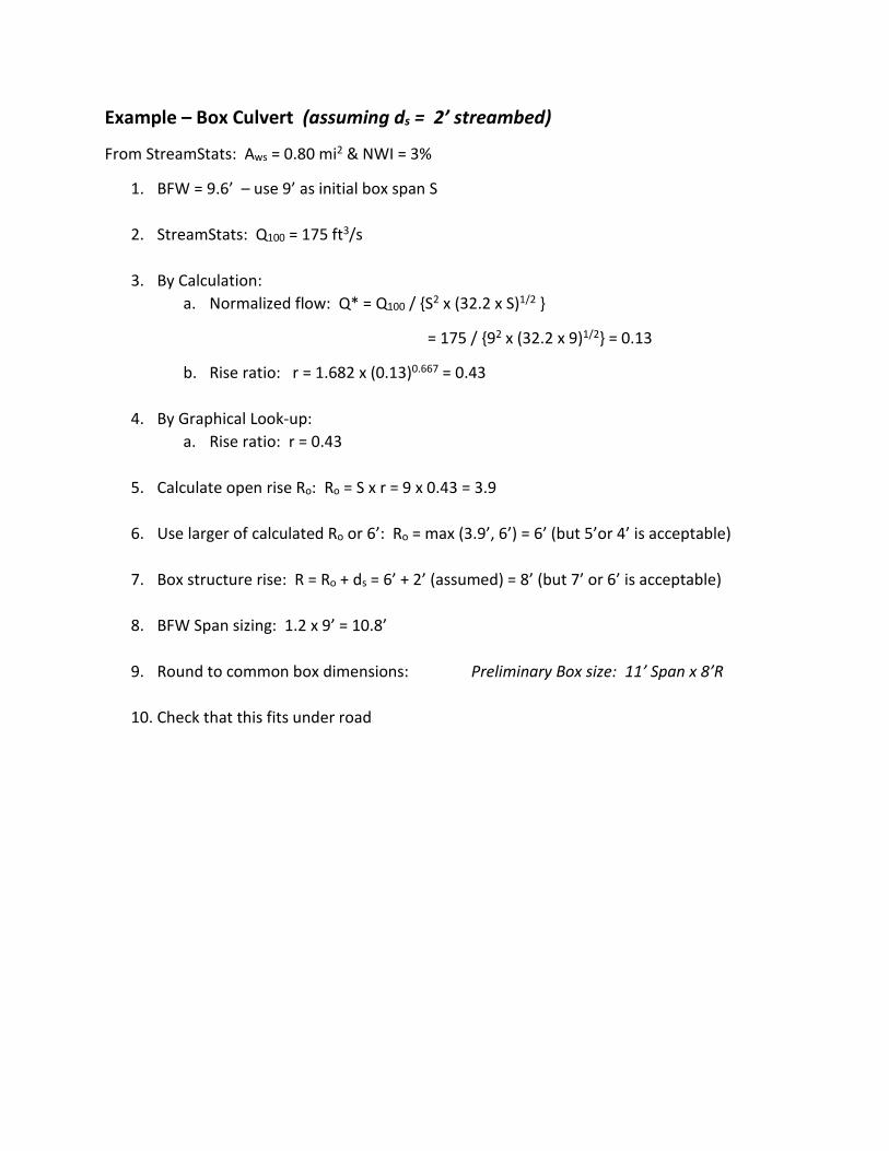
Example – Box Culvert (assuming ds = 2’ streambed)
From StreamStats: Aws = 0.80 mi2 & NWI = 3%
1. BFW = 9.6’ – use 9’ as initial box span S
2. StreamStats: Q100 = 175 ft3/s
3. By Calculation: a. Normalized flow: Q* = Q100 / {S2 x (32.2 x S)1/2 }
= 175 / {92 x (32.2 x 9)1/2} = 0.13
b. Rise ratio: r = 1.682 x (0.13)0.667 = 0.43
4. By Graphical Look-up: a. Rise ratio: r = 0.43
5. Calculate open rise Ro: Ro = S x r = 9 x 0.43 = 3.9
6. Use larger of calculated Ro or 6’: Ro = max (3.9’, 6’) = 6’ (but 5’or 4’ is acceptable)
7. Box structure rise: R = Ro + ds = 6’ + 2’ (assumed) = 8’ (but 7’ or 6’ is acceptable)
8. BFW Span sizing: 1.2 x 9’ = 10.8’
9. Round to common box dimensions: Preliminary Box size: 11’ Span x 8’R
10. Check that this fits under road

0
100
200
300
400
500
600
700
800
900
1000
0.00 0.05 0.10 0.15
Q10
0(ft
3 /s)
Q* = Q/{S2 x (gS)1/2}
0.0
0.1
0.2
0.3
0.4
0.5
0.00 0.05 0.10 0.15
r = R
o/S
Q* = Q/{S2 x (gS)1/2}
S=8
10
12
14
16
S=18S=2022S=26 24
S = _____ ft
r = _____
Ro = S x r = _____
Q100 =
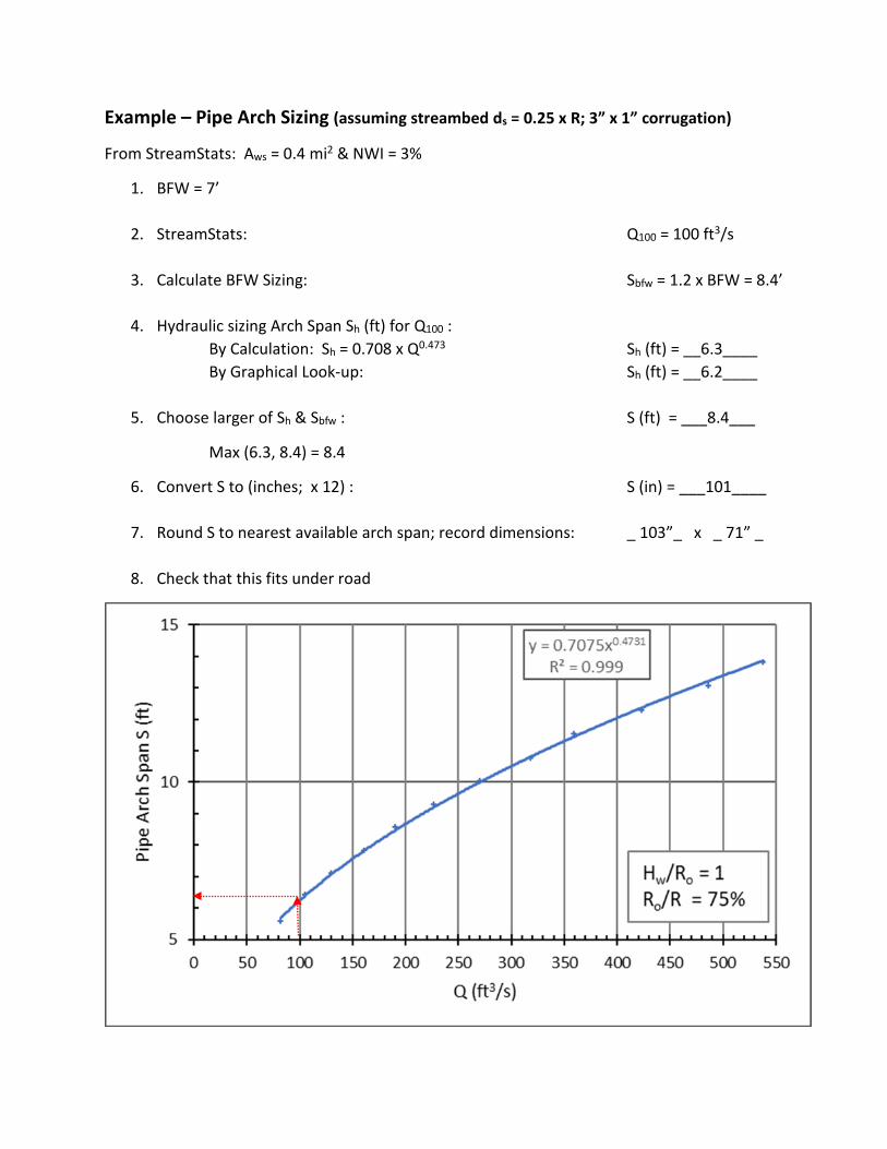
Example – Pipe Arch Sizing (assuming streambed ds = 0.25 x R; 3” x 1” corrugation)
From StreamStats: Aws = 0.4 mi2 & NWI = 3%
1. BFW = 7’
2. StreamStats: Q100 = 100 ft3/s
3. Calculate BFW Sizing: Sbfw = 1.2 x BFW = 8.4’
4. Hydraulic sizing Arch Span Sh (ft) for Q100 : By Calculation: Sh = 0.708 x Q0.473 Sh (ft) = __6.3____ By Graphical Look-up: Sh (ft) = __6.2____
5. Choose larger of Sh & Sbfw : S (ft) = ___8.4___
Max (6.3, 8.4) = 8.4
6. Convert S to (inches; x 12) : S (in) = ___101____
7. Round S to nearest available arch span; record dimensions: _ 103”_ x _ 71” _
8. Check that this fits under road
Related Documents