1 Copyright © 2013 by ASME Proceedings of the ASME 2013Pressure Vessels & Piping Division Conference PVP 2013 July 14-18, 2013, Paris, France PVP2013-97642 MAIN ISSUES ON THE SEISMIC DESIGN OF INDUSTRIAL PIPING SYSTEMS AND COMPONENTS FabrizioPaolacci Department of Engineering University Roma Tre Rome, Italy Email: [email protected] Md. Shahin Reza Department of Civil, Environmental and Mechanical Engineering, University of Trento Trento, Italy Email: [email protected] Oreste S. Bursi Department of Civil, Environmental and Mechanical Engineering, University of Trento Trento, Italy Email: [email protected] Arnold M. Gresnigt Civil Engineering and Geosciences Delft University of Technology Delft, The Netherlands Email: [email protected] Anil Kumar Department of Civil, Environmental and Mechanical Engineering, University of Trento Trento, Italy Email: [email protected] ABSTRACT A significant number of damages in piping systems and components during recent seismic events have been reported in literature which calls for a proper seismic design of these structures. Nevertheless, there exists an inadequacy of proper seismic analysis and design rules for a piping system and its components. Current seismic design Codes are found to be over conservative and some components, e.g., bolted flange joints, do not have guidelines for their seismic design. Along this line, this paper discusses about the main issues on the seismic analysis and design of industrial piping systems and components. Initially, seismic analysis and component design of refinery piping systems are described. A review of current design approaches suggested by European (EN13480:3) and American (ASME B31.3) Codes is performed through a Case Study on a piping system. Some limits of available Codes are identified and a number of critical aspects of the problem e. g., dynamic interaction between pipes and rack, correct definition of the response factor and strain versus stress approach, are illustrated. Finally, seismic performance of bolted flange joints based on the results of experimental investigations carried out by the University of Trento, Italy, will be discussed. INTRODUCTION In petroleum industries, especially in refinery installations, hundreds of miles of pipes are installed to transfer raw and refined materials (fluid and gas) from a point to another of the plant, connecting all the components involved in the transformation process (tanks, distillations columns, furnaces, etc.). Therefore, piping systems represent key structures that deserve particular attention. Unfortunately, few contributions in the literature are available, in order to clarify the seismic requirements that piping systems have to comply with. In addition, aspects like action and structural modeling have not yet been treated in a satisfactorily manner. Moreover, current American and European Standards do not contain enough rules and details for a proper seismic analysis and design of piping systems. Along these lines, some problems relevant to seismic analysis criteria of piping systems are addressed in this paper. In a greater detail, several aspects that characterize the problem are treated: 1) modeling of pipes and pipe-racks; 2) selection of

Welcome message from author
This document is posted to help you gain knowledge. Please leave a comment to let me know what you think about it! Share it to your friends and learn new things together.
Transcript
1 Copyright © 2013 by ASME
Proceedings of the ASME 2013Pressure Vessels & Piping Division Conference PVP 2013
July 14-18, 2013, Paris, France
PVP2013-97642
MAIN ISSUES ON THE SEISMIC DESIGN OF INDUSTRIAL PIPING SYSTEMS AND COMPONENTS
FabrizioPaolacci Department of Engineering
University Roma Tre Rome, Italy
Email: [email protected]
Md. Shahin Reza Department of Civil, Environmental and
Mechanical Engineering, University of Trento Trento, Italy
Email: [email protected]
Oreste S. Bursi Department of Civil, Environmental and
Mechanical Engineering, University of Trento Trento, Italy
Email: [email protected]
Arnold M. Gresnigt Civil Engineering and Geosciences
Delft University of Technology Delft, The Netherlands
Email: [email protected]
Anil Kumar Department of Civil, Environmental and
Mechanical Engineering, University of Trento Trento, Italy
Email: [email protected]
ABSTRACT
A significant number of damages in piping systems and
components during recent seismic events have been reported in literature which calls for a proper seismic design of these structures. Nevertheless, there exists an inadequacy of proper seismic analysis and design rules for a piping system and its components. Current seismic design Codes are found to be over conservative and some components, e.g., bolted flange joints, do not have guidelines for their seismic design. Along this line, this paper discusses about the main issues on the seismic analysis and design of industrial piping systems and components. Initially, seismic analysis and component design of refinery piping systems are described. A review of current design approaches suggested by European (EN13480:3) and American (ASME B31.3) Codes is performed through a Case Study on a piping system. Some limits of available Codes are identified and a number of critical aspects of the problem e. g., dynamic interaction between pipes and rack, correct definition of the response factor and strain versus stress approach, are illustrated. Finally, seismic performance of bolted flange joints
based on the results of experimental investigations carried out by the University of Trento, Italy, will be discussed.
INTRODUCTION
In petroleum industries, especially in refinery installations,
hundreds of miles of pipes are installed to transfer raw and refined materials (fluid and gas) from a point to another of the plant, connecting all the components involved in the transformation process (tanks, distillations columns, furnaces, etc.). Therefore, piping systems represent key structures that deserve particular attention. Unfortunately, few contributions in the literature are available, in order to clarify the seismic requirements that piping systems have to comply with. In addition, aspects like action and structural modeling have not yet been treated in a satisfactorily manner. Moreover, current American and European Standards do not contain enough rules and details for a proper seismic analysis and design of piping systems. Along these lines, some problems relevant to seismic analysis criteria of piping systems are addressed in this paper. In a greater detail, several aspects that characterize the problem are treated: 1) modeling of pipes and pipe-racks; 2) selection of

2 Copyright © 2013 by ASME
the analysis method; 3) definition of the seismic action; 4) dynamic analysis of the system; 5) stress analysis of pipes; 6) definition of the ultimate capacity of pipes and joints between pipes.
To this end, a representative Case Study of an actual piping system is analyzed herein. Thus the requirements of American and European Codes are compared and important aspects are highlighted: a) definition of numerical models for seismic analysis, b) seismic input and analysis methods, c) piping stress analysis and checks d) evaluation of the ultimate capacity of pipes and joints necessary for a correct design of a structure, as suggested by modern approaches like Performance-Based Engineering. Finally, a discussion on the main results of an experimental activity on a flange joint carried out at University of Trento, Italy, allowed highlighting the conservativeness of current Standards.
CODES AND STANDARS FOR THE SEISMIC DESIGN OF PIPING SYSTEMS
Nowadays, both European and American Codes are
available for the design of piping systems under seismic events. The main European contribution is chiefly represented by the Standard EN13480, dedicated to metallic piping systems [1]. The Eurocode 8 - part 4, the European seismic Code for industrial components, is also devoted to pipelines, but only of above-ground type, which differs from metallic piping system for many aspects.
American experience on piping system is very rich, especially in terms of design standardization and seismic design calculation, and the long list of Standards and Codes available it is a clear demonstration of it. The main Standard is represented by ASME B31.3 [2], but many other contributions and guidelines are also available [3, 4].
The seismic analysis of a piping system involves several basic steps that allow defining the proper seismic action, the suitable numerical model and analysis method and the verification format to be used. European (EN13480:3-2002) and American Standards (ASME B31.3-2006) for piping systems differ for several of these aspects. Thus, in order to understand these differences and the consequences on the seismic response evaluation, in the following both European and American Standards are applied to a representative Case Study.
It is necessary to stress that the American Standard does not contain explicit indications on the seismic analysis of piping systems, but rather refers to the American Standard for seismic analysis of structures, ASCE7-05, which includes all the required prescriptions. On the contrary the European Standard contains an entire Annex (A) dedicated to the dynamic and seismic analysis of piping systems, but does not contain explicit quantification of the seismic action. At this end, the Eurocode 8 (EN1998:1 2004) should be used.
DESCRIPTION OF THE CASE STUDY The piping system analyzed herein belongs to a refinery, as
shown in Fig. 1. The support steel structure is composed of seven transverse moment resisting frames placed every 6 m, realized with commercial HEA/B steel profiles. In the longitudinal direction, it behaves like a truss structure, which is reinforced with 6 braces. Horizontal bracings are also installed to avoid excessive relative displacements between the pipe supports. The piping system presents a typical piping layout with pipes having different diameters. To simplify the analysis, only the structural contribution of 8’’ pipes has been considered. The remaining pipes are considered only as weight. Several flanged elbows are present within the pipe-rack and at both ends of the piping system.
Fig. 1The piping system model. Pipes may contain several fluids, such as Amine, cooling
water and high to medium pressure steam. The vertical loads corresponding to the weight of the pipes, insulation and fluid are considered as uniformly distributed equal to 12 kN/m. The main characteristics of the piping system are: i) Structural steel S-275 JR, ii) pipe steel A106 Grade B, iii) pipes with diameter of 8’’, iv) pressure of the pipes 0.5÷5 MPa, v) Temperature range 47 °C ÷360 °C, vi) Importance factor Ip=1.5, vi) PGA=0.24 g, viii) Soil conditions D.
MAIN ISSUES IN SEISMIC DESIGN OF PIPING SYSTEMS
The seismic design of a piping system entails a number of
issues. As stated above, they are essentially related to the modeling of the structure, to a correct definition of the seismic action, to a proper analysis method to be applied, and finally, to an appropriate design method to be used. In addition, nowadays, the Load and Resistance Factor Design method (LRFD) is certainly the standard method for designing structures and the allowable stress design method is by now abandoned because it is often considered highly conservative. Unfortunately, this latter is still the current approach for

3 Copyright © 2013 by ASME
designing a piping system. This represents a limit to be overcome. But, to the purpose, it is first necessary to understand the limit of such an approach; and the more direct way is to apply the Codes prescriptions to a Case Study, trying to individuate limits and drawbacks. In doing this, it seems appropriate to compare European and American experiences, applying both EN13480:3 and ASME B31.3 to the Case Study described above, along with a comparison of the results regarding all the treated aspects.
DEFINITION OF NUMERICAL MODELS OF PIPING SYSTEMS
A synthetic scheme of what European and American Standards prescribe for a correct numerical modeling of a piping system and the definition of the seismic conditions is reported in Tab 1.
Table 1 clearly shows that the suggested numerical model to use in seismic analysis is always elastic both for EN13480 and ASME B31.3. This choice comes certainly from the old way to evaluate the safety level of a structure: the allowable stress method still diffused in designing of piping systems. Usually, only the piping system is modeled, using the supporting structure only to evaluate the seismic action at pipes level (e.g., in-structure spectra). The supporting structure (e.g. pipe-tack) is treated as elastic too. The assumption of elastic behavior would not be a strong limitation if a correct value of the behavior factor were adopted. Some comments on this aspect will be provided afterward.
Tab. 1 Code prescriptions for numerical modeling Code Model
type Analysis Seismic
condition Dynamic interact.
Relative motion
Pipe models
EN 13480
Elastic (1) Equivalent Static Modal (G,IS4) Time-History
SSE (2) OBE
NO YES Beam elements (FF and SIF)
ASME B31.3
Elastic Static Modal Time-History
SSE YES/NO YES Beam elements (FF and SIF)(3)
(1) elastic calculation shall be used although some part might be exhibit plastic deformations (p. 4.1), (2) SSE=safe shutdown earthquake, OBE= Occasional operation condition, (3) FF=Flexibility Factor, SIF= Stress Intensification Factor, (4) G=ground motion spectra, IS=In-structure spectra. A key point in modeling a piping system is the possibility to neglect the interaction (static and dynamic) between the pipes and the supporting structure. EN13480 does not provide any indication about it, whereas ASME B31.3, by means of ASCE-07, prescribes a crude rule based on the ratio, W, between the weights of pipes and supporting structure. In particular, if W< 25% the interaction can be excluded and the piping system can be considered as a non-building structure, loaded by a seismic action coming from the supporting structure at pipes level.
This rule has been recently analyzed by several authors. For example, in [5] the rule has been analyzed using time-history analysis. From the results and discussion, the author concluded that in some cases this decoupling rule could produce gross errors in the evaluation of the dynamic behavior of piping systems. In particular, it seems that in dynamic assessment of such systems, in addition to the primary-secondary system weight ratio criteria, attention should be paid to other aspects as “end conditions of pipes”, “relative stiffness of supporting structure to piping system” and “relative stiffness of pipes to pipe-supports”, even though only partial conclusions where reached by the authors, that suggested more investigations on this matter. In the literature many works have been dedicated to the problem of dynamic coupling between primary and secondary systems [6-8],but the results are difficult to be extended to the case of piping systems for several reasons, but mainly because in case of piping systems, the secondary system is composed by more sub-systems (pipes with different diameters, different end conditions, different supports, etc.). Therefore, assumption of a single secondary system could lead to gross errors in response prediction of piping systems.
For example, in Fig. 2 the ratio between the bending moments in the pipes determined using the entire structure (Ms) and only the pipe (Mp) is shown for different values of W (%) and for different floors considered.
Fig. 2 Influence of W on the seismic response of the piping system.
For W ≥ 25%, the influence could be extremely important.
For example, for W = 50%, the bending moment increases up to 6 times if the pipe is placed at 3rd floor, whereas the increasing is limited for lower values of W and floors. From this simple example, the 25% of weight rule suggested by ASCE guidelines seems to be rational, even if cannot be a unique decision variable to take into account or not the dynamic coupling between pipes and support structure. In this respect, the stiffness effect should also be considered.
Concerning the Case Study, applying the weight ratio rule, dynamic interaction has been considered, because W> 25%. Moreover, for comparison, this rule has also been considered in applying the European Standard. In order to evaluate the
4 Copyright © 2013 by ASME
effectiveness of the weight rule, the behavior of the piping system without pipe-rack has also been analyzed.
The pipes are usually connected to the pipe-rack by mechanical supports, often flexible. They are usually designed to accommodate thermal and pressure effects, avoiding excessive stress in the pipes. Unfortunately, no indications on how to model them are provided by European and American Standards. Nevertheless, this is an important aspect that has to be treated with particular attention because it can change dynamic behavior of the system. Dissipative supports can be used instead of traditional ones in order to introduce artificially more damping and reduce the response of the pipes.
The analyzed case presents a quite stiff support system, modeled as elastic spring in the transverse direction (Y), leaving free the relative displacements in longitudinal direction (X) and using fix restraints conditions in vertical direction. Moreover, as usual, all the rotations between pipe and pipe-rack have been unrestrained.
Another relevant aspect about modeling of piping systems is the adoption of a proper model for pipes and fittings (elbows, tee-joints, nozzles, etc.). At this regards, usually beam elements with hollow section are used for straight pipes. The fittings are also modeled using beam elements, but modifying the stiffness for the effect of geometry. For this purpose, both European and American Codes define a flexibility factor (k >1) using which the moment of inertia of the pipe is reduced. In addition, to take into account the stress concentration effect, the Stress Intensification Factor (SIF) is used to increase the stress calculated using the beam theory. The values of k and SIF calculated according to EN13480 and ASME B31.3 are very similar.
Alternatively, it is possible to use shell elements to model fittings [9]. This approach is appropriate to account for ovalization of the section and stiffening pressure effect also in non-linear field [23]. For these reasons, this model has been used for the Case Study and a comparison with beam model has been carried out. We can anticipate that the numerical simulations have shown a similar behavior of both the models and the reliability of modified beam element, at least for standard fittings, like the one analyzed here. Therefore, in what follows, only the results of the more refined one will be shown.
A last but not less important aspect regards the boundary conditions of the pipes. In fact, because a piping system is realized by hundreds of miles of pipes, the analysis involves necessarily a limited part of the structure. Consequently, proper boundary conditions have to be accurately adopted to simulate the remaining part of the structure. Also for this delicate aspect no indications are provided by the European and American Standards. As already shown in literature, the correct boundary conditions may cause important modifications of the dynamics of the piping system but the correct choice depends on the single case [5].
Because one of the aims of this work is to compare European and American Standards, it has been decided to limit the possible cases adopting as restraint conditions of the pipe ends only hinges.
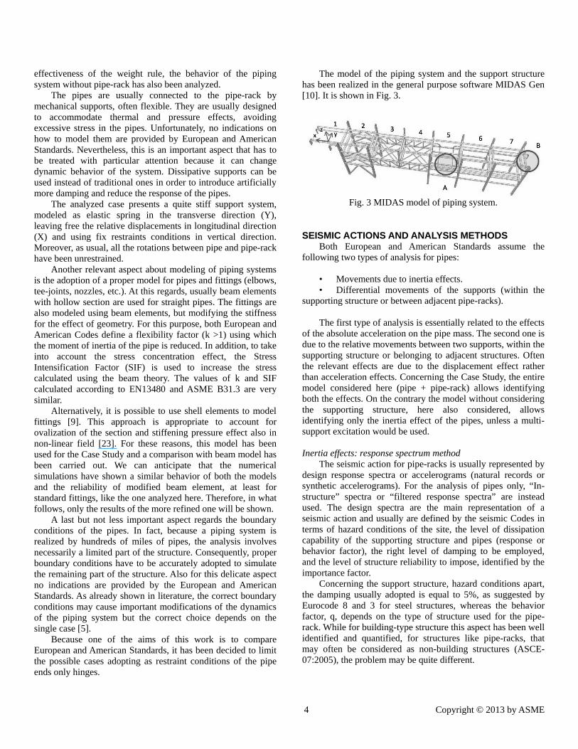
The model of the piping system and the support structure has been realized in the general purpose software MIDAS Gen [10]. It is shown in Fig. 3.
Fig. 3 MIDAS model of piping system.
SEISMIC ACTIONS AND ANALYSIS METHODS Both European and American Standards assume the
following two types of analysis for pipes: • Movements due to inertia effects. • Differential movements of the supports (within the
supporting structure or between adjacent pipe-racks). The first type of analysis is essentially related to the effects
of the absolute acceleration on the pipe mass. The second one is due to the relative movements between two supports, within the supporting structure or belonging to adjacent structures. Often the relevant effects are due to the displacement effect rather than acceleration effects. Concerning the Case Study, the entire model considered here (pipe + pipe-rack) allows identifying both the effects. On the contrary the model without considering the supporting structure, here also considered, allows identifying only the inertia effect of the pipes, unless a multi-support excitation would be used. Inertia effects: response spectrum method
The seismic action for pipe-racks is usually represented by design response spectra or accelerograms (natural records or synthetic accelerograms). For the analysis of pipes only, “In-structure” spectra or “filtered response spectra” are instead used. The design spectra are the main representation of a seismic action and usually are defined by the seismic Codes in terms of hazard conditions of the site, the level of dissipation capability of the supporting structure and pipes (response or behavior factor), the right level of damping to be employed, and the level of structure reliability to impose, identified by the importance factor.
Concerning the support structure, hazard conditions apart, the damping usually adopted is equal to 5%, as suggested by Eurocode 8 and 3 for steel structures, whereas the behavior factor, q, depends on the type of structure used for the pipe-rack. While for building-type structure this aspect has been well identified and quantified, for structures like pipe-racks, that may often be considered as non-building structures (ASCE-07:2005), the problem may be quite different.

5 Copyright © 2013 by ASME
The current American and European seismic Codes provide a q factor for steel racks equal to 3 ½ and 4 respectively (Tab 2). This choice probably derives from the hypothesis of no-coupling between the rack (primary system) and the pipes (secondary system). In fact, usually the level of dynamic coupling between pipes and rack can be neglected. But in other some cases its influence cannot be excluded a priori [5].
In order to compare the results of EN13480 and ASME B31.3 the same elastic spectrum defined according to EN1998:1has been adopted, and modified using the behavior factor of Tab. 2. It is shown in Fig. 4.
The spectral responses of the modal oscillators are then combined to obtain the resultant response of the system. Moreover, the resultant forces and displacements from bi-directional analysis are typically obtained by the square root sum of square of the response in each direction, or by applying the well-known 100-30 rule.
Tab. 2 Behavior factor q
Code q pipe-rack)
q factor (pipe)
Damping
(%)
Importance F.
EN13480 4 Not indicated 5 1.5 ASME B31.3
3 ¼ 6÷12 5 1.5
Fig. 4 Elastic spectra of accelerograms.
Fig. 5 Main vibration mode with and w/o pipes.
The modal analysis on the entire system allowed to highlight the important role of the pipes in realizing structural coupling between the several frames of the pipe-rack. In this respect, the vibration modes of the rack with and without the pipes are shown in Fig. 5. The period of the first mode of the rack with and without pipes is similar, whereas the excited mass is higher in the first case, showing the coupling effect of the transverse frames due to the pipes.
For the Case Study, Incremental Dynamic Analysis allowed to evaluate the real q-factor. Fig. 6 shows the dynamic pushover curves for each accelerogram. Each dot corresponds to a given value of PGA measured at a specific point at last floor. It is noticed the limited plastic deformations level of the structure that suggest a value of q∼2. This value has been adopted in the application of the analysis spectrum method.
Fig. 6 Dynamic pushover curve of the piping system.
Inertia effects: in-structure spectrum method
The in-structure spectra allow a seismic action to be defined for single pipes at several floors of the pipe-rack, in which the pipe is placed. Both European and American Codes provide their explicit expressions. They are defined as the spectrum acceleration multiplied by the amplification factor AF shown in Tab. 3. The expression of the amplification factor expressed by EN13480 (EC8) and ASME B31.3 (ASCE-07) differs for the presence of the period ratio Ta/T1, presents only in the seismic European Standard which takes into account the dynamic interaction between pipes (Ta) and pipe-rack (T1); see Tab. 3. The symbols in Tab. 3 are those indicated in the relevant Codes.
The behavior factor provided by the Codes, especially by the American one, seems to be overestimated. For example, ASCE-07 prescribes the use of a behavior factor 6 or 12 according to the deformability of the material used. In some cases this hypothesis may not be totally true.
For example, in 1996 Okeil and Tung [11], using an idealized piping system, suggested a closed-form formula that provides the reduction factor q as function of the ductility of the support structure and the ratio of the piping frequency and the frequency of the seismic action. The reduction, q, increases with the ductility. Moreover, the stiffer is the piping system (low values of f) is, the higher is the q. In any case, q is never
Base
shea
r[kN
]
Displacement [m]

6 Copyright © 2013 by ASME
greater than 3-4. These results are in contrast with the provisions of ASCE-07.
Tab. 3Code-based in-structure spectra Code Expression
ASME B31.3 (ASCE-07)
Fp=Ip0.4apSDSWp
RpAF
AF= �1+2zH�
EN13480:3 (EC8)
Fa=IpagSWp
Rp AF
AF= �3 �1+ z
H�
1+ �1- Ta
T1�
2 -12�
Instead of using static method that employs seismic force of Tab. 3, a dynamic approach is also possible that uses generated floor response spectra, whose shape is based on typical Soil-Structure interaction theory. For industrial piping systems, few contributions have been found in literature [12-15].
For the Case Study of Fig. 1, floor spectra have been generated by using time-history analysis. Fig. 7 shows the floor spectra for one the three accelerograms used in Time-History analysis (see next section), from which the filtering effect of the pipe-rack is clear. The maximum amplification is now restricted to the range 2-3 Hz, whereas, the ground acceleration spectra was placed in the range 2-6 Hz. The labels Frame 1, 3 and 5 correspond to the labels of the frames indicated in Fig.3. It is also possible to note the variability of the maximum amplification effect within the structure. The maximum acceleration peak is found at frame 3; this is because more mass is placed there with respect to the other frames.
Because natural frequencies of piping systems are typically in the range 15-40 Hz, the amplification effect due to the inertia is very limited. In fact, the maximum acceleration applied to the pipes corresponds more or less to the maximum acceleration at floors in which pipes are placed, some peaks a part, at frequency 7 and 10 Hz
A possible representation of floor spectra for the case-study is shown in Fig.7 as envelopes of the mean spectra at several frames. This allows to account for the spatial variability of the action and its frequency content. This has been used to get the response of the pipes analyzed individually. Inertia effects: Time-History analysis method
A time history seismic input is rarely used for the design or retrofit of piping systems. Often it is used to generate facility specific response spectra analyses, or as a research tool, to study in detail the full non-linear behavior of a component or system as a function of time.
Nowadays, the scientific community has widely accepted the use of natural records to re-produce a real input, for several reasons. For many engineering applications, the purpose of selection and scaling of real earthquake is to fit the Code design
spectrum considering the seismological and geological parameters of the specific site. To comply with the seismic Codes set of accelerograms, regardless its type, basically the following criteria should be matched:
• minimum of 3 accelerograms should be used; • the mean of the zero period spectral response
acceleration values (calculated from the individual time histories) should not be smaller than the value of ag× S for the site in question (S is the soil factor, ag is the ground acceleration);
• in the range of periods between 0.2 T1 and 2 T1, where T1 is the fundamental period of the structure in the direction where the accelerogram will be applied, no value of the mean 5% damping elastic spectrum, calculated from all time histories, should be <90% of the corresponding value of the 5% damping elastic response spectrum.
Fig. 7 Case Study – Mean floor spectra for several frames and
Envelope Floor Spectrum. To help engineers in selecting a proper set of records, some
tools have been proposed in the literature. The most recent is REXEL proposed by Iervolino et al [16].
More rarely, artificial or synthetic accelerograms are used. The first ones are generated to match a target response spectrum, the second ones form from seismological source models and accounting for path and site effects. For artificial signals, even though, it is possible to obtain acceleration time series that are almost completely compatible with the elastic design spectrum, the generated accelerograms often have an excessive number of cycles of strong motion, and consequently have unrealistically high-energy content. For this reason are less used than natural records. Moreover, to generate synthetic accelerograms there is a need for a definition of a specific earthquake scenario in terms of magnitude, rupture mechanism in addition to geological conditions and location of the site. Generally, most of this information is not often available, particularly when using seismic design Codes. This representation of a seismic input is rarely used.
According to the above considerations, non-linear dynamic analysis, considering the support structure with nonlinear fiber elements and pipes modeled as elastic beam elements, has been
0
0.5
1
1.5
2
2.5
3
3.5
4
4.5
5
0 5 10 15 20
Acce
lera
tion
(g)
Frequency (Hz)
Frame 5Frame 3Frame 1Envelope

7 Copyright © 2013 by ASME
performed in MIDAS using a set of 7 accelerograms compatible with the EC8 spectrum for Soil B (Fig.4) and selected from the Pacific Earthquake Engineering Research center database (http://peer.berkeley.edu) according to a Magnitude range 6-7, a distance from the epicenter < 30 km, and a PGA in the range 0.25-0.35 g. These parameters are referred for the Case Study to the Operating Basis Earthquake (OBE) condition, for which after the seismic event the operating conditions of the plant should be still assured [15]. Differential movement effects
Seismic anchor motion (or “SAM”) is the differential motion between pipe support attachment points (for example, supports attached to an upper floor would sway with the building, with a larger amplitude than supports attached at a lower elevation), or the differential motion between equipment nozzles and pipe supports. Seismic anchor movements are input as displacements (translations and rotations) at the support attachments or at equipment nozzles. The resulting stresses and loads in the piping system can be properly combined to obtain stress and loads in the pipes.
No specific indications are provided by EN13480:3, whereas, ASCE-07 provides a simplified criterion based on the elastic analysis of the pipe-rack. Here, it is suggested to evaluate first the relative displacements between two connection points within the structure and at the same level for each vibration modes and then to combine them using a proper combination rule as the SRSS rule.
Unlike the cases of differential movements between adjacent pipe-racks connected by pipes, this effect on pipes within the structure can be usually neglected.
VERIFICATION METHODS One of the fundamental steps for the qualification of a pipe
system is the fulfillment of some limits of the pipe stress or strain, for a given working condition. For a seismic action, usually the two working conditions indicated in Tab. 1 are used (OBE, SSE).
In order to evaluate the safety level, stress-based or strain-based approach can be used. The first approach intends to evaluate the maximum stress in the pipes and the calculation is usually based on elastic analysis of the structure.
While stress-based approach for pipelines is acceptable for a material with a well-defined yield point and with well-defined yield ductility and strength, this design criteria becomes invalid when the stress in pipelines exceeds the limit under some displacement control loads, such as earthquakes [18]. In this case, strain-based approach provides the design rule where the strain in the pipeline is allowed to exceed the specified yield strain provided that the safe operation can be ensured under displacement load. This method allows selected extensions to the stress-based design possibilities to take advantage of steel’s well-known ability to deform plastically, but remain a stable structure. Codes and Standards are available for the strain based
design approach; see [18] for reference. With the strain-based approach, maximum strain in the pipes is calculated and compared with specified strain-limits related to limit states usually identified with buckling or ovalization of the pipes [24],[25]. Unfortunately, this approach needs the calculation of the seismic response in the non-linear range. This is one of the reasons why the stress approach is mostly used. In particular, only EN13480 contains explicit indications for calculating the pipe stresses limits, considering both the above conditions (OBE and SSE), whereas ASME B31.3 indicates only occasional load conditions that can be identified as OBE condition.
Usually the OBE condition is regarded as service condition and thus applicable to the ASD approach. SBE is instead referred to an ultimate limit state and thus more referred to a SSE condition. Even if not explicitly defined by EN13480, that is limited to the definition of the previous seismic conditions, this rule is suggested here.
EN13480 provides at point 12.3.3 Eq. (1) to evaluate longitudinal stresses due to sustained, occasional and exceptional loads (e.g. earthquakes). This comes from the beam theory and includes internal pressure P and the resultant moments due to the sustained loads (MA) and the earthquake (MB):
0.754
A BpD M MSIFt Z
σ += + × (1)
where SIF is the stress intensification factor (equal to one for straight pipes) (EN13480, 2002); MA and MB are the resultant force for dead loads and the earthquake, respectively; p is the internal pressure; D, t and Z is the diameter, thickness and Inertia modulus of the pipe, respectively.
ASME B31.3 at point 319.4.4 indicates the way to calculate the resultant moments, similar to that of EN13480:3. In particular:
( ) ( )22zzyyR MSIFMSIFM ×+×= (2)
Studies have shown that the present Standards for piping
system design under seismic loads are over conservative and modifications have been proposed to relax this over conservatism [19, 20]. For example, [20] has applied the present Codes to calculate the stress limit on piping systems and experimental results showed significant discrepancy from the real behavior. This aspect has been treated for example in [21].
EN13480 includes a paragraph which is dedicated to the definition of the allowable stress calculation. Allowable stress is defined according to the conditions previously recalled: Operating Basic Earthquake (OBE) and Safe Shutdown Earthquake (SSE). The basic inequality to be respected is:
hkf≤σ (3)
8 Copyright © 2013 by ASME
where σ = maximum stress in the pipes due to the sustained and seismic loads. k = 1.2 for OBE k = 1.8 for SSE fh = is the basic allowable stress given by Code
ASME B31.3 does not provide explicit differentiation
between OBE and SSE but refers to a Design Earthquake that can be identified with the OBE. It is prescribed that the maximum stress cannot be greater than 1.33 times the basic allowable stress for pipes, indicated in the Appendix A of the same Code.
SEISMIC RESPONSE EVALUATION The results for each analysis method applied to the Case
Study presented in the previous chapters are reported in Table 4 in terms of moments along the local axes y and z of the pipe. The resultant moment, MR, of the single moments along local axes y and z, calculated according to the EN13480:3 and ASME B31.3 are also shown. The maximum moment is found near the left edge of the rack (bay 2), even if similar values are also obtained within bay 6 and 7.
Table 4 Maximum moment in the pipe
Method Bay M (kNm)
1 2 3 4 5 6 7
SA My 1.52 0.84 1.01 0.95 1.02 0.85 1.80 Mz 1.44 0.66 1.07 0.78 0.84 0.65 1.71
DA-FSA
My 3.58 7.09 3.80 3.80 1.97 2.46 2.49 Mz 6.81 9.77 9.77 11.6 11.6 9.58 7.94
DA-RSA
My 0.61 7.32 4.61 4.61 2.94 1.41 1.41 Mz 13.6 13.8 13.8 8.42 9.71 12.5 12.4
DA-NTHA
My 1.56 6.91 5.98 4.94 5.04 3.47 2.50 Mz 13.8 15.3 14.2 7.01 8.75 15.8 15.9
SA=Static analysis, DA-FSA=Floor spectrum analysis, DA-RSA=response spectrum method, DA-NTHA=nonlinear T-H analysis
In addition, the maximum stress level of the pipe in the
same points has been calculated according to the Eq.(1), obtaining a mean value in case of non-linear T-H analysis about 86 MPa against the allowable stress indicated in Tab.5.
Table 5 Allowable stresses in the pipe
Code OBE (MPa) SSE (MPa) EN13480:3 166 249 ASME B31.3 156 ---
The above calculations confirm that, using allowable stress
approach and then comparing the capacity with the demand
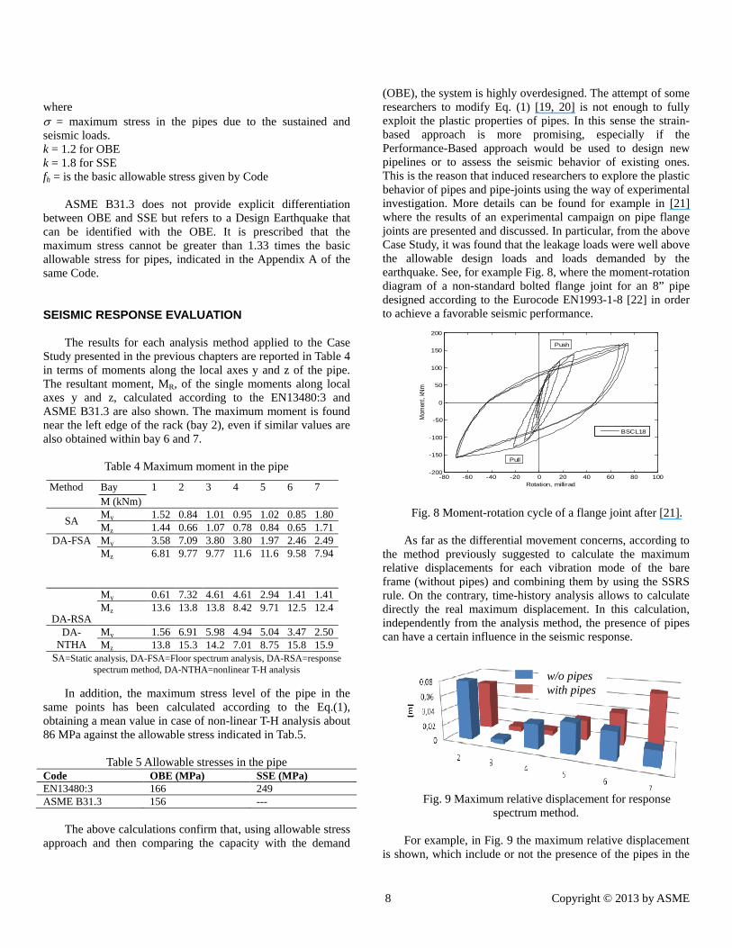
(OBE), the system is highly overdesigned. The attempt of some researchers to modify Eq. (1) [19, 20] is not enough to fully exploit the plastic properties of pipes. In this sense the strain-based approach is more promising, especially if the Performance-Based approach would be used to design new pipelines or to assess the seismic behavior of existing ones. This is the reason that induced researchers to explore the plastic behavior of pipes and pipe-joints using the way of experimental investigation. More details can be found for example in [21] where the results of an experimental campaign on pipe flange joints are presented and discussed. In particular, from the above Case Study, it was found that the leakage loads were well above the allowable design loads and loads demanded by the earthquake. See, for example Fig. 8, where the moment-rotation diagram of a non-standard bolted flange joint for an 8” pipe designed according to the Eurocode EN1993-1-8 [22] in order to achieve a favorable seismic performance.
Fig. 8 Moment-rotation cycle of a flange joint after [21]. As far as the differential movement concerns, according to
the method previously suggested to calculate the maximum relative displacements for each vibration mode of the bare frame (without pipes) and combining them by using the SSRS rule. On the contrary, time-history analysis allows to calculate directly the real maximum displacement. In this calculation, independently from the analysis method, the presence of pipes can have a certain influence in the seismic response.
Fig. 9 Maximum relative displacement for response
spectrum method. For example, in Fig. 9 the maximum relative displacement
is shown, which include or not the presence of the pipes in the
-80 -60 -40 -20 0 20 40 60 80 100-200
-150
-100
-50
0
50
100
150
200
Rotation, millirad
Mom
ent,
kNm
BSCL18
Push
Pull
w/o pipes with pipes

9 Copyright © 2013 by ASME
support structure model. It can be noted that the presence of pipes reduces the displacements, especially in central part of the pipe, whereas it is influenced by the boundary conditions in case the presence of the pipe is considered.
In Tab. 6, the maximum relative displacements for both the DA-RSA and DA-NTHA methods are reported. The influence of pipes in the relative displacement of the piping is evident. Moreover, the displacements calculated using DA-NTHA analysis method are always the lesser, especially in the central part of the pipe (bay 2-6).
This corresponds to a certain degree of conservatism inherent in the combination of the several vibration modal responses using SSRS rule.
Table 6 maximum relative displacements (in meter)
bay 1 2 3 4 5 6 7 SS
pipes RSM 0.030 0.070 0.089 0.086 0.072 0.054 0.039 T-H 0.037 0.053 0.003 0.024 0.026 0.026 0.020
SS RSM 0.034 0.078 0.086 0.082 0.002 0.074 0.130 T-H 0.041 0.043 0.003 0.021 0.021 0.026 0.050
SS= support structure, SS pipe= support structure + pipes
CONCLUSIONS The seismic analysis of piping systems is very different
from the analysis of like-building structures for which a long experience has permitted to have enough provisions for obtaining a reliable design against earthquakes. Therefore, the present contribution tried to clarify all the design steps of this type of structures and to identify all the aspects that need to be clarified. This was made through a representative Case Study analyzed according to both European (EN13480:3) and American Standards (ASME B31.3) devoted to piping systems. With reference to a typical piping system, the comparison between EN13480 and ASME B31.3 Standards showed that the two Codes provide similar indications for the evaluation of the seismic response of pipelines supported by a pipe-rack. From the analysis of the results the following conclusions, considered valid for both the Standards, can be drawn.
The usual way of designing piping systems is based on the allowable stress approach. This means that the structure is considered elastic. Consequently, only an operating basis earthquake condition (OBE) can be taken into account for design. Conversely, the modern approach to the seismic design of structures is to differentiate serviceability from ultimate limit states. This latter condition could be represented, for example, by the Safe Shutdown Earthquake (SEE). The problem is that a proper definition of the deformation capability of the pipes and fittings (ovalization, etc.) in the plastic range would be necessary, and on this aspect the research has not reached solid conclusions. But the advantages would be several and first of all the design optimization. For example, in the analyzed case, we are very far from the moment capacity of a bolted flange joint located in the pipeline. This high level of conservatism seems to be in contrast with the modern Performance-Base design approach, for which a certain level of yielding in the structure is admitted according to a specific performance. For
instance, it would be possible to accept in pipes a certain level of yielding on the condition that leakage would not occur, and the consequence, for example, to accept a reduction of the thickness of the flange.
ACKNOWLEDGMENTS The work presented herein is carried out with a financial
grant from the Research Fund for Coal and Steel of the European Commission, within the INDUSE project: “Structural Safety Of Industrial Steel Tanks, Pressure Vessels and Piping Systems under Seismic Loading”, Grant No. RFSR-CT-2009-00022.
REFERENCES [1] EN13480-3- Metallic industrial piping - Part 3: Design
and calculation, June, 2002. [2] ASME Code for Pressure Piping, B31 - ASME B31.3-
2006 (Revision of ASME B31.3-2004) [3] American Lifelines Alliance - Seismic Design and
Retrofit of Piping Systems, 2002 [4] Guidelines for the Seismic Design of Oil and Gas Piping
Systems, Committee on Gas and Liquid Fuel Lifelines of the ASCE Technical Council on Lifeline Earthquake Engineering, 1984
[5] Azizpour, O, Hosseisni, M., 2009,“A verification of ASCE Recommended Guidelines for seismic evaluation and design of combination structures in petrochemical facilities,” J. of Applied Sciences.
[6] Asfura, A., and Kiureghian, A. D., 1986, “Floor response spectrum method for seismic analysis of multiply supported secondary systems,” Earthquake Engineering & Structural Dynamics, 14: 245–265. doi: 10.1002/eqe.4290140206.
[7] Burdisso, R. A., and Singh, M. P., 1987,“Multiply supported secondary systems part I: Response spectrum analysis,” Earthquake Engineering & Structural Dynamics, 15: 53–72. doi: 10.1002/eqe.4290150105.
[8] Saudy A., Ghobarah A., Aziz, T., S., 1992, “A modified CCFS approach for the seismic analysis of multiply supported MDOF secondary systems,” Nuclear Engineering and Design, Volume 133, Issue 2, March 1992, Pages 183-197, ISSN 0029-5493, DOI: 10.1016/0029-5493(92)90179-Y.
[9] DeGrassi, G. and Hofmayer, C., 2005, “Seismic analysis of simplified piping systems for the NUPEC ultimate strength piping test program,” NUREG/CR-6889, by Brookhaven National Laboratory for the US, Nuclear Regulatory Commission, December, 2005.
[10] MIDAS [2010] - Gen 2010 (v1.1), Midas Information Technology Co. Ltd., 2010.
[11] Okeil, A., Tung, C., 1996, “Effects of ductility on seismic response of piping systems and their implication on design and qualification,” Nuclear Engineering and Design, 166: 69-83.

10 Copyright © 2013 by ASME
[12] HalilSezen, M.ASCE, and Andrew, S., Whittaker, M.ASCE, 2006, “Seismic Performance of Industrial Facilities Affected by the 1999 Turkey Earthquake,” Journal of Performance of Constructed Facilities, Vol. 20, No. 1, February 1, 2006. ©ASCE, ISSN 0887-3828/2006/1-28–36/$25.00.
[13] Eshghi,S., and Razzaghi M. S.,“The Behavior of Special Structures During the Bam Earthquake of 26 December 2003,” JSEE: Special Issue on Bam Earthquake, 197-207.
[14] 2007 Niigata Chuetsu-Oki Japan Earthquake, Reconnaissance Report, http://www.grmcat.com/images/Niigata-Chuetsu-Oki-Japan-Report.pdf
[15] Gupta A. K., Jaw J. W., 1986,“A new in-structure response spectrum (IRS) method for multiply connected secondary systems with coupling effects,” Nuclear Engineering and Design, Volume 96, Issue 1, September 1986, Pages 63-80, ISSN 0029-5493, DOI: 10.1016/0029-5493(86)90162-7.
[16] Iervolino, I., Galasso, C., Cosenza, E., 2009,“REXEL: computer aided record selection for code-based seismic structural analysis,” Bulletin of Earthquake Engineering, 8:339-362. DOI 10.1007/s10518-009-9146-1.
[17] Paolacci, F., Reza, M. S., Bursi, O. S.,2011, “Seismic design criteria of refinery piping systems,” COMPDYN 2011 -III ECCOMAS Thematic Conference on Computational Methods in Structural Dynamics and Earthquake Engineering, Corfu, Greece, 26–28 May 2011.
[18] Kobayashi,H., Ochi, Y., 1989, “Dynamic response of piping system on rack structure with gaps and friction,” Nuclear Engineering and Design,111: 341-350.
[19] Touboul, F., Sollogoub, P., Blay, N., 1999, “Seismic behaviour of piping systems with and with-out defects: experimental and numerical evaluations,” Nuclear Engineering and Design 192 (1999) 243–260.
[20] Touboul, F., Blay, N., Sollogoub, P., Chapuliot, S., 2006,“Enhanced seismic criteria for piping,”Nuclear Engineering and Design 236 (2006) 1–9.
[21] Bursi, O.S., Reza, M.S., Kumar, A., Paolacci, F., 2012,“Seismic Performance of Bolted Flange Joints in Piping Systems for Oil and Gas Industries,” 15WCEE, Lisbon, September, 2012.
[22] EN 1993-1-8, 2005,“Eurocode 3: Design of steel structures - Part 1-8: Design of joints.”
[23] Karamanos, S. A., Giakoumatos, E. and Gresnigt, A. M., 2003, "Nonlinear Response and Failure of Steel Elbows Under In-Plane Bending and Pressure," Journal of PressureVessel Technology, ASME, Vol. 125, No. 4, pp. 393-402, November 2003.
[24] Karamanos, S. A., Tsouvalas, D. and Gresnigt, A. M., 2006, "Ultimate Bending Capacity andBuckling of Pressurized 90 deg Steel Elbows," Journal of Pressure VesselTechnology, ASME, Vol. 128, No. 3, pp. 348-356, August 2006.
[25] Varelis, G. E., Karamanos, S. A., and Gresnigt, A. M., 2013, "Steel Elbow Response Under Strong Cyclic Loading," Journal of Pressure Vessel Technology, ASME, Vol. 135,No.1, Article Number: 011207, February 2013.
Related Documents