Main Index Aliver Orangery Index.................................................................................................. A01 - A02 Profiles Specification Pages............................................................................ A03 - A06 Technical Information......................................................................... A07 - A08 Scale Profile Drawings....................................................................... A09 - A14 Accessories Photos & Drawings............................................................................. B03 - B15 Sections Scale Elevations................................................................................. C03 - C05 Statics................................................................................................ D01 - D02 Construction Drawings EHE119 Corner Detail........................................................................ E03 HEA905 Punch Tool........................................................................... E04 Hip to Eaves....................................................................................... E05 HEA350 Hip End Cap......................................................................... E06 Ridge & Hip........................................................................................ E07 Crown Assembly................................................................................ E08 Rafter to Ridge................................................................................... E09 Rafter to Eaves................................................................................... E10 HEA352 Rafter End Cap.................................................................... E11 EHE128 Glass End Cover.................................................................. E12 Installation Details.............................................................................. E13 - E14 Tie Bar Detail..................................................................................... E15 Sawing Tables Cutting Information............................................................................. F01 - F02 EHE Index A EHE B EHE C EHE D EHE E EHE F EHE A01 PAGE ISSUED : OCTOBER 2018

Welcome message from author
This document is posted to help you gain knowledge. Please leave a comment to let me know what you think about it! Share it to your friends and learn new things together.
Transcript
Main Index
Aliver Orangery
Index.................................................................................................. A01 - A02
Profiles
Specification Pages............................................................................
A03 - A06
Technical Information......................................................................... A07 - A08
Scale Profile Drawings.......................................................................
A09 - A14
Accessories
Photos & Drawings.............................................................................
B03 - B15
Sections
Scale Elevations................................................................................. C03 - C05
Statics................................................................................................ D01 - D02
Construction Drawings
EHE119 Corner Detail........................................................................ E03
HEA905 Punch Tool........................................................................... E04
Hip to Eaves.......................................................................................
E05
HEA350 Hip End Cap.........................................................................
E06
Ridge & Hip........................................................................................
E07
Crown Assembly................................................................................
E08
Rafter to Ridge...................................................................................
E09
Rafter to Eaves................................................................................... E10
HEA352 Rafter End Cap....................................................................
E11
EHE128 Glass End Cover.................................................................. E12
Installation Details.............................................................................. E13 - E14
Tie Bar Detail..................................................................................... E15
Sawing Tables
Cutting Information.............................................................................
F01 - F02
EHEIndex
AEHE
BEHE
CEHE
DEHE
EEHE
FEHE
A01PAGE
ISSUED : OCTOBER 2018

Aliver Orangery
Updates
DATE PAGE DESCRIPTION
---------------------------------------------------------------------------------------------------------------------
------------------------------------------------------------------------------------------------------------------------------------------------------
------------------------------------------------------------------------------------------------------------------------------------------------------
A02PAGE
ISSUED : OCTOBER 2018
Aug 2018 B07, B08
B10, C03
E04
E06, E07
E14, F02
HEA345 revised to HEA345N.
HEA370 crown seal added.
HEA905 punch tool added.
HEA372 gasket added to EHE119.
Tie bar detail added.
Specification
Aliver Orangery
GENERAL DESCRIPTION
The "Aliver Orangery" roof system described in this manual is designed to offer a modern aluminium lantern
roof with narrow sightlines and concealed fixings.
Aliver Orangery has a fixed pitch of 25°.
The system has been designed to make fabrication and site assembly a quick and simple process.
PROFILES : SPECIFICATION PAGES
For advise on Aliver Orangery sizes outside of the recommended design limitations, please contact the
Technical Department at Smart Systems Ltd Tel: 01934 876100
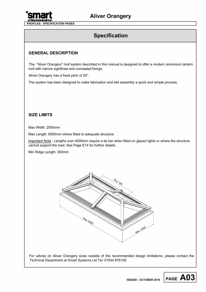
SIZE LIMITS
Max Width: 2000mm
Max Length: 6000mm where fitted to adequate structure.
Important Note - Lengths over 4000mm require a tie bar when fitted on glazed lights or where the structure
cannot support the load. See Page E14 for further details.
Min Ridge Length: 300mm
A03PAGE
ISSUED : OCTOBER 2018
M
a
x
.
2
0
0
0
M
a
x
.
6
0
0
0
M
i
n
.
3
0
0
Specification
Aliver Orangery
PROFILES : SPECIFICATION PAGES
PROFILE SPECIFICATION
The roof sections are constructed of aluminium alloy extrusion to BS EN 755-9 and BS EN 12020, extruded
from 6060 T6 alloy. The internal and external extrusions of the eaves beam and glass stop are separated
with a polyamide thermal break.
The external aluminium alloy extrusion is pre-treated and finished either:-
a) Anodised to BS 3987: 1987, grade AA25 to a natural self colour.
b) Polyester powder organic coating to BS 6496. Dual colour is available.
GENERAL MANUFACTURING
The roof is made by cutting the frame profiles with accurate 45° mitred ends or 90° square ends using
Tungsten Carbide Tipped Saw Blades, operating at approximately 3000 rpm.
Eaves beam joints are formed with machine screws into extruded cleats through the mitred ends of the
section.
Hip and rafter joints to the eaves beam are formed by fixing through the eaves beam into the relevant
bracket with M5 machine screws.
Hip to ridge joints are formed by fixing each section to the crown bracket with machine screws. An additional
clamp plate screw is also used at each joint for reinforcement.
Rafter to ridge joints are formed using an M5 rivnut into the side of the ridge to form a fixing for the bracket.
The rafter is then fixed to the bracket using M5 machine screws.
On polyester powder coated finishes, great care should be taken to avoid getting gap sealer on visible
surfaces and should be removed as soon as possible with a clean cloth.
Care should be exercised when using products not supplied by Smart Systems Ltd as no responsibility can
be accepted.
A04PAGE
ISSUED : OCTOBER 2018
Specification
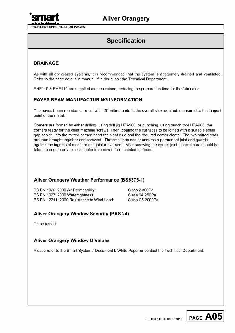
DRAINAGE
As with all dry glazed systems, it is recommended that the system is adequately drained and ventilated.
Refer to drainage details in manual, if in doubt ask the Technical Department.
EHE110 & EHE119 are supplied as pre-drained, reducing the preparation time for the fabricator.
EAVES BEAM MANUFACTURING INFORMATION
The eaves beam members are cut with 45° mitred ends to the overall size required, measured to the longest
point of the metal.
Corners are formed by either drilling, using drill jig HEA900, or punching, using punch tool HEA905, the
corners ready for the cleat machine screws. Then, coating the cut faces to be joined with a suitable small
gap sealer. Into the mitred corner insert the cleat glue and the required corner cleats. The two mitred ends
are then brought together and screwed. The small gap sealer ensures a permanent joint and guards
against the ingress of moisture and joint movement. After screwing the corner joint, special care should be
taken to ensure any excess sealer is removed from painted surfaces.
Aliver Orangery
PROFILES : SPECIFICATION PAGES
Aliver Orangery Weather Performance (BS6375-1)
BS EN 1026: 2000 Air Permeability: Class 2 300Pa
BS EN 1027: 2000 Watertightness: Class 6A 250Pa
BS EN 12211: 2000 Resistance to Wind Load: Class C5 2000Pa
Aliver Orangery Window U Values
Please refer to the Smart Systems' Document L White Paper or contact the Technical Department.
Aliver Orangery Window Security (PAS 24)
To be tested.
A05PAGE
ISSUED : OCTOBER 2018
Specification
Aliver Orangery
PROFILES : SPECIFICATION PAGES
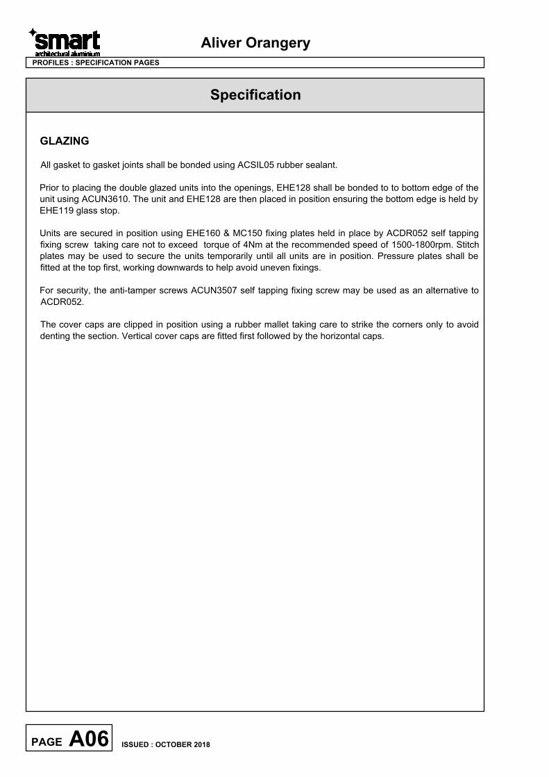
GLAZING
All gasket to gasket joints shall be bonded using ACSIL05 rubber sealant.
Prior to placing the double glazed units into the openings, EHE128 shall be bonded to to bottom edge of the
unit using ACUN3610. The unit and EHE128 are then placed in position ensuring the bottom edge is held by
EHE119 glass stop.
Units are secured in position using EHE160 & MC150 fixing plates held in place by ACDR052 self tapping
fixing screw taking care not to exceed torque of 4Nm at the recommended speed of 1500-1800rpm. Stitch
plates may be used to secure the units temporarily until all units are in position. Pressure plates shall be
fitted at the top first, working downwards to help avoid uneven fixings.
For security, the anti-tamper screws ACUN3507 self tapping fixing screw may be used as an alternative to
ACDR052.
The cover caps are clipped in position using a rubber mallet taking care to strike the corners only to avoid
denting the section. Vertical cover caps are fitted first followed by the horizontal caps.
A06PAGE
ISSUED : OCTOBER 2018
Number Picture
Page
Perim.
mm
Mec.
mm
Length
Pack
pr.
MF SA KL HP M
lx(cm4)
wx(cm3)
ly(cm4)
wy(cm3)
Aliver Orangery
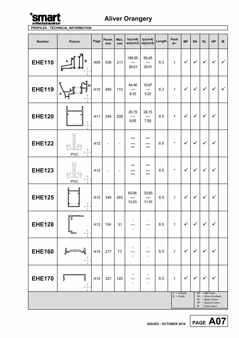
EHE110
536 211
188.55
----
26.01
85.45
----
20.01X
XYY
6.31A09
PROFILES : TECHNICAL INFORMATION
üüüü
üüüü
üüüü
üüüü
üüüü
üüüüü
üüüüü
EHE119
489 110
44.46
----
8.33
10.07
----
3.22
6.3 1A10
EHE120
294 208
25.79
----
9.05
24.15
----
7.50
6.5 1A11
EHE125
349 262
33.65
----
11.81
63.06
----
13.53
6.5 1A12
EHE170
221 120 6.5 1A14
EHE160
217 776.5
A14
EHE122
***
----
***
***
----
***
6.5 *A12
X
XYY
X
X
YY
X
XYY
X
XYY
X
XYY
X
XYY
X
XYY
X
XYY
A B
A
B
üüüüEHE128
154 31
-
----
-
-
----
-
6.5A13 1
1
MF
SA
KL
HP
= Mill Finish
= Silver Anodised
= Basic Colour
= Special Colour
A = Outside
B = Inside
M = Dual Colour
A07PAGE
ISSUED : OCTOBER 2018
PVC
-
----
-
-
----
-
-
----
-
-
----
-
--
üüüüEHE123
***
----
***
***
----
***
6.5 *A12
PVC
--
üüüü
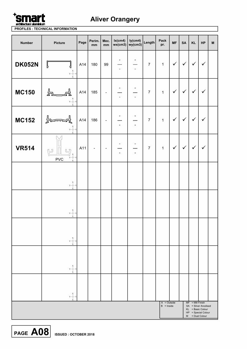
üüüüDK052N
180 99 7A14
MC150
185 7A14
Aliver Orangery
VR514
- -
X
XYY
7A11
PROFILES : TECHNICAL INFORMATION
üüüü
X
X
YY
X
X
YY
X
XYY
X
XYY
X
XYY
X
XYY
X
XYY
X
XYY
1
1
1
Number Picture
Page
Perim.
mm
Mec.
mm
Length
Pack
pr.
MF SA KL HP M
lx(cm4)
wx(cm3)
ly(cm4)
wy(cm3)
MF
SA
KL
HP
= Mill Finish
= Silver Anodised
= Basic Colour
= Special Colour
A = Outside
B = Inside
M = Dual Colour
A08PAGE
ISSUED : OCTOBER 2018
MC152
üüüü186 7A141
PVC
-
----
-
-
----
-
-
----
-
-
----
-
-
----
-
-
----
-
-
----
-
-
----
-
-
-
Primary Visible Side Secondary Visible Side
Scale 1:1
Aliver Orangery
PROFILE : SCALED PROFILE DRAWINGS
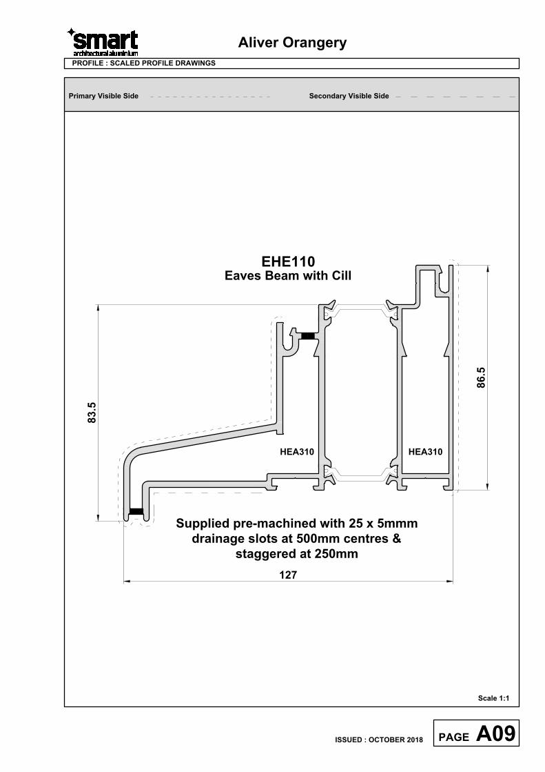
EHE110
Eaves Beam with Cill
86.5
127
83.5
HEA310 HEA310
A09PAGE
ISSUED : OCTOBER 2018
Supplied pre-machined with 25 x 5mmm
drainage slots at 500mm centres &
staggered at 250mm
Scale 1:1
Primary Visible Side Secondary Visible Side
Aliver Orangery
PROFILE : SCALED PROFILE DRAWINGS
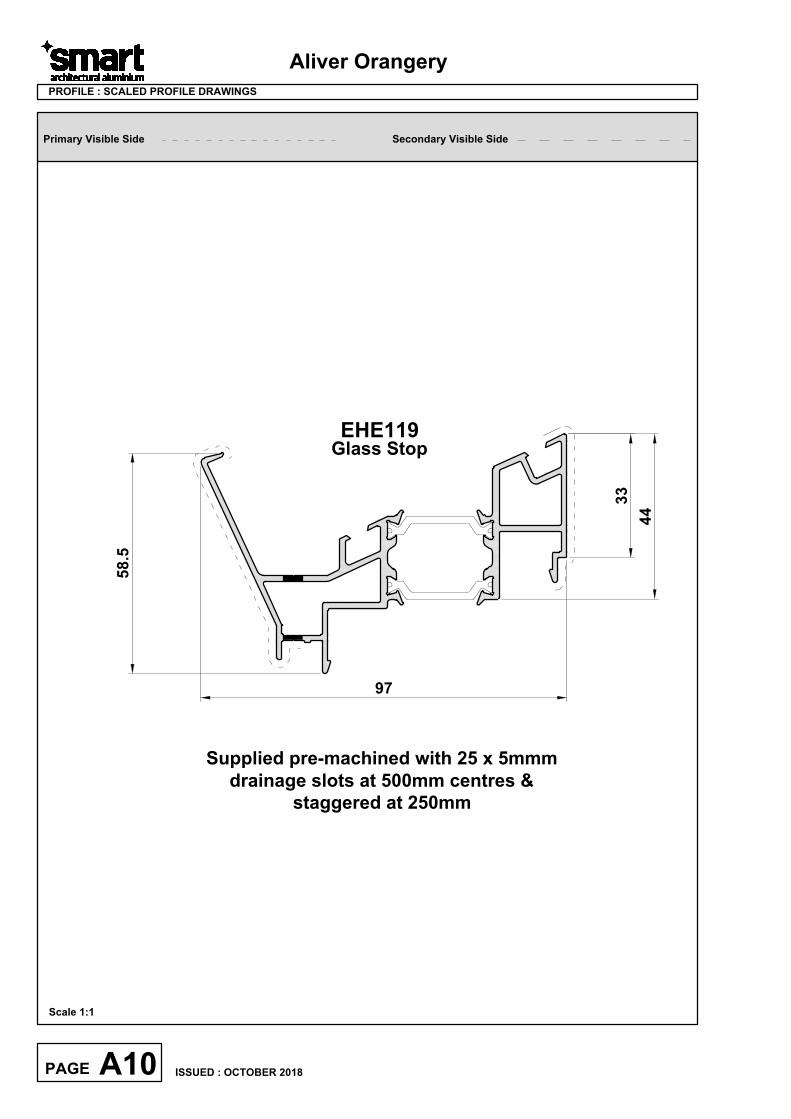
EHE119
Glass Stop
44
97
58.5
A10PAGE
ISSUED : OCTOBER 2018
Supplied pre-machined with 25 x 5mmm
drainage slots at 500mm centres &
staggered at 250mm
33
Primary Visible Side Secondary Visible Side
Aliver Orangery
PROFILE : SCALED PROFILE DRAWINGS
Scale 1:1
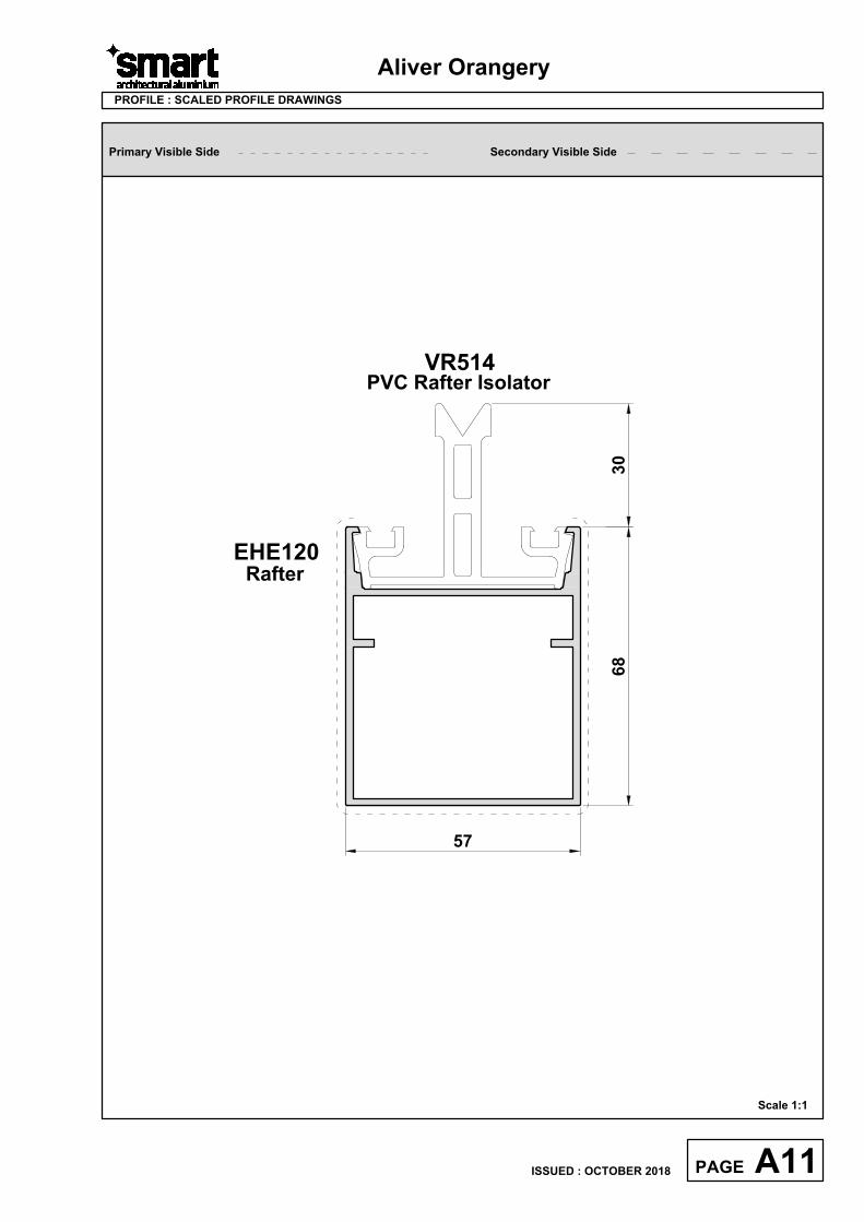
EHE120
Rafter
68
57
VR514
PVC Rafter Isolator
A11PAGE
ISSUED : OCTOBER 2018
30
Primary Visible Side Secondary Visible Side
Aliver Orangery
PROFILE : SCALED PROFILE DRAWINGS
Scale 1:1
A12PAGE
ISSUED : OCTOBER 2018
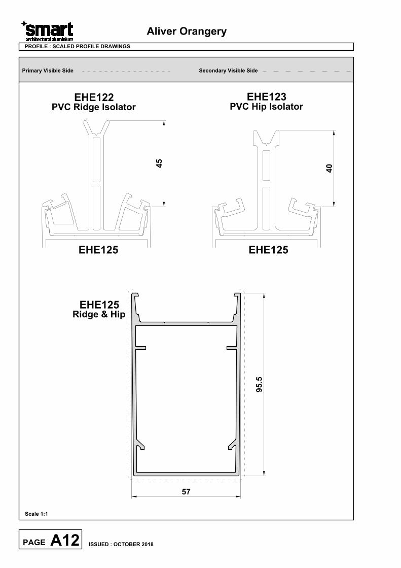
EHE125
Ridge & Hip
95.5
57
EHE122
PVC Ridge Isolator
45
EHE125
EHE123
PVC Hip Isolator
40
EHE125
Primary Visible Side Secondary Visible Side
PROFILE : SCALED PROFILE DRAWINGS
Scale 1:1
2
8
.
4
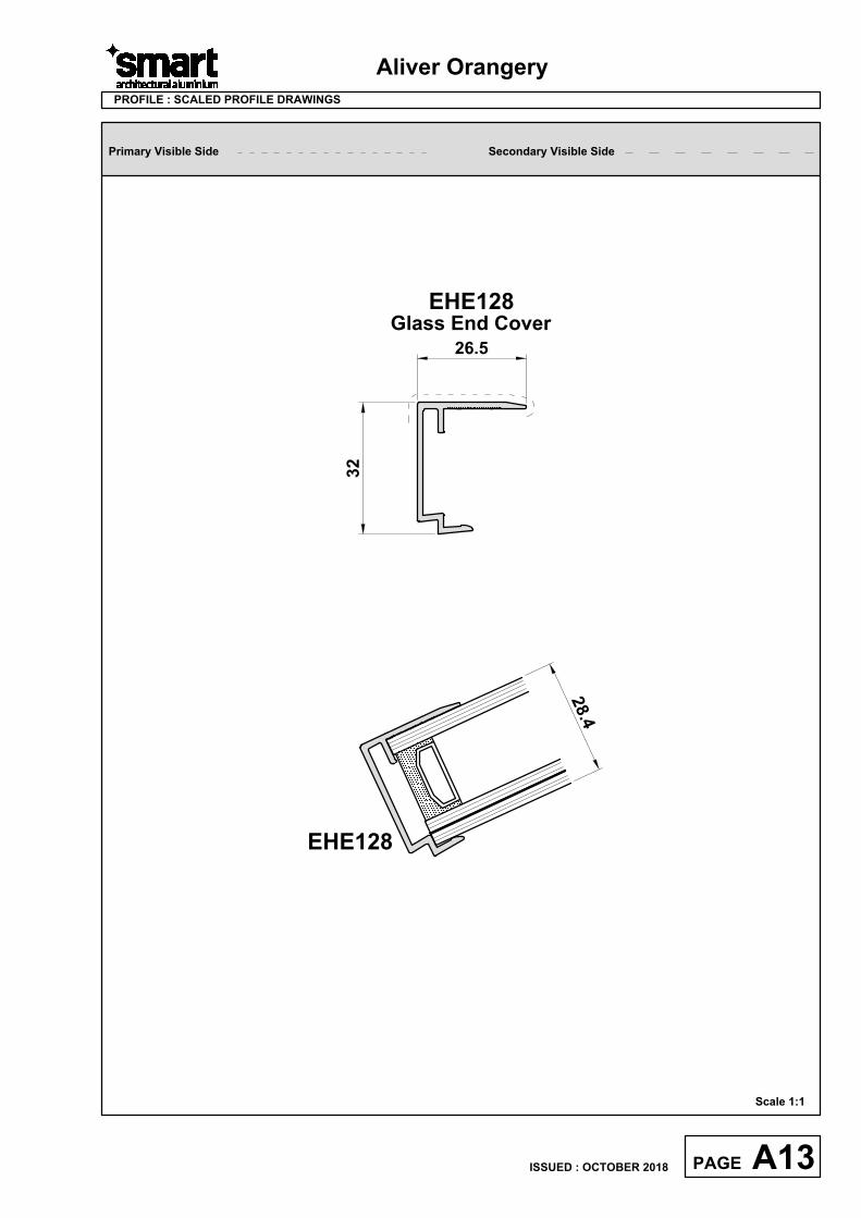
EHE128
26.5
32
EHE128
Glass End Cover
Aliver Orangery
A13PAGE
ISSUED : OCTOBER 2018
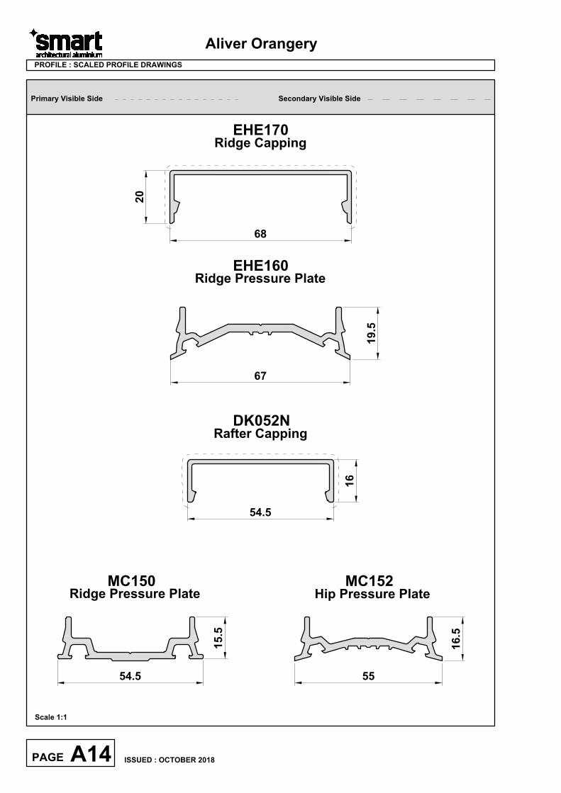
Primary Visible Side Secondary Visible Side
PROFILE : SCALED PROFILE DRAWINGS
Scale 1:1
Ridge Pressure Plate
EHE170
Ridge Capping
68
20
EHE160
15.5
67
19.5
DK052N
Rafter Capping
MC150
Ridge Pressure Plate
54.5
16
54.5
Aliver Orangery
A14PAGE
ISSUED : OCTOBER 2018
16.5
55
MC152
Hip Pressure Plate
Aliver Orangery
Section B
Accessories
Photos & Drawings
B01PAGE
ISSUED : OCTOBER 2018
Aliver Orangery
B02PAGE
ISSUED : OCTOBER 2018
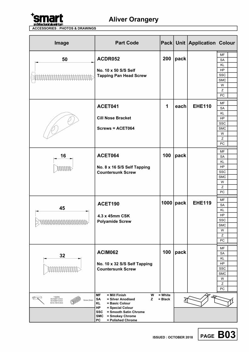
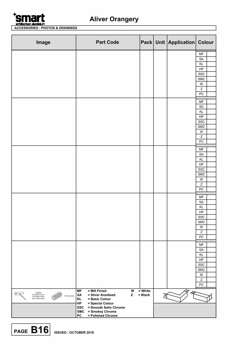
ColourImage Part Code Pack Unit Application
Aliver Orangery
ACDR052
No. 10 x 50 S/S Self
Tapping Pan Head Screw
200 pack
ACET041
Cill Nose Bracket
Screws = ACET064
EHE1101 each
ACET064
No. 8 x 16 S/S Self Tapping
Countersunk Screw
100 pack
B03PAGE
ACCESSORIES : PHOTOS & DRAWINGS
50
16
T-BARS
ACVG65=2.5mm
ACVG66=3.0mm
ACVL150=4.0mm
Screw (Grub)
W
Z
PC
MF
SA
KL
HP
SSC
SMC
W
Z
PC
MF
SA
KL
HP
SSC
SMC
W
Z
PC
MF
SA
KL
HP
SSC
SMC
W
Z
PC
MF
SA
KL
HP
SSC
SMC
W
Z
PC
MF
SA
KL
HP
SSC
SMC
MF = Mill Finish W = White
SA = Silver Anodised Z = Black
KL = Basic Colour
HP = Special Colour
SSC = Smooth Satin Chrome
SMC = Smokey Chrome
PC = Polished Chrome
ISSUED : OCTOBER 2018
100 packACIM062
No. 10 x 32 S/S Self Tapping
Countersunk Screw
32
ACET190
4.3 x 45mm CSK
Polyamide Screw
1000 pack
45
EHE119
AutoCAD SHX Text
X
AutoCAD SHX Text
Y
AutoCAD SHX Text
X
AutoCAD SHX Text
Y
ColourImage Part Code Pack Unit Application
Aliver Orangery
B04PAGE
ACCESSORIES : PHOTOS & DRAWINGS
T-BARS
ACVG65=2.5mm
ACVG66=3.0mm
ACVL150=4.0mm
Screw (Grub)
W
Z
PC
MF
SA
KL
HP
SSC
SMC
W
Z
PC
MF
SA
KL
HP
SSC
SMC
W
Z
PC
MF
SA
KL
HP
SSC
SMC
W
Z
PC
MF
SA
KL
HP
SSC
SMC
W
Z
PC
MF
SA
KL
HP
SSC
SMC
MF = Mill Finish W = White
SA = Silver Anodised Z = Black
KL = Basic Colour
HP = Special Colour
SSC = Smooth Satin Chrome
SMC = Smokey Chrome
PC = Polished Chrome
ISSUED : OCTOBER 2018
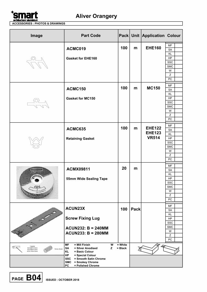
ACMC150
Gasket for MC150
100 m MC150
ACMC019
Gasket for EHE160
100 m EHE160
ACUN23X
Screw Fixing Lug
ACUN232: B = 240MM
ACUN233: B = 280MM
100 Pack
ACMC635
Retaining Gasket
100 m EHE122
EHE123
VR514
ACMX09811
55mm Wide Sealing Tape
20 m
AutoCAD SHX Text
X
AutoCAD SHX Text
Y
AutoCAD SHX Text
X
AutoCAD SHX Text
Y
ColourImage Part Code Pack Unit Application
Aliver Orangery
B05PAGE
ACCESSORIES : PHOTOS & DRAWINGS
T-BARS
ACVG65=2.5mm
ACVG66=3.0mm
ACVL150=4.0mm
Screw (Grub)
W
Z
PC
MF
SA
KL
HP
SSC
SMC
W
Z
PC
MF
SA
KL
HP
SSC
SMC
W
Z
PC
MF
SA
KL
HP
SSC
SMC
W
Z
PC
MF
SA
KL
HP
SSC
SMC
W
Z
PC
MF
SA
KL
HP
SSC
SMC
MF = Mill Finish W = White
SA = Silver Anodised Z = Black
KL = Basic Colour
HP = Special Colour
SSC = Smooth Satin Chrome
SMC = Smokey Chrome
PC = Polished Chrome
ISSUED : OCTOBER 2018
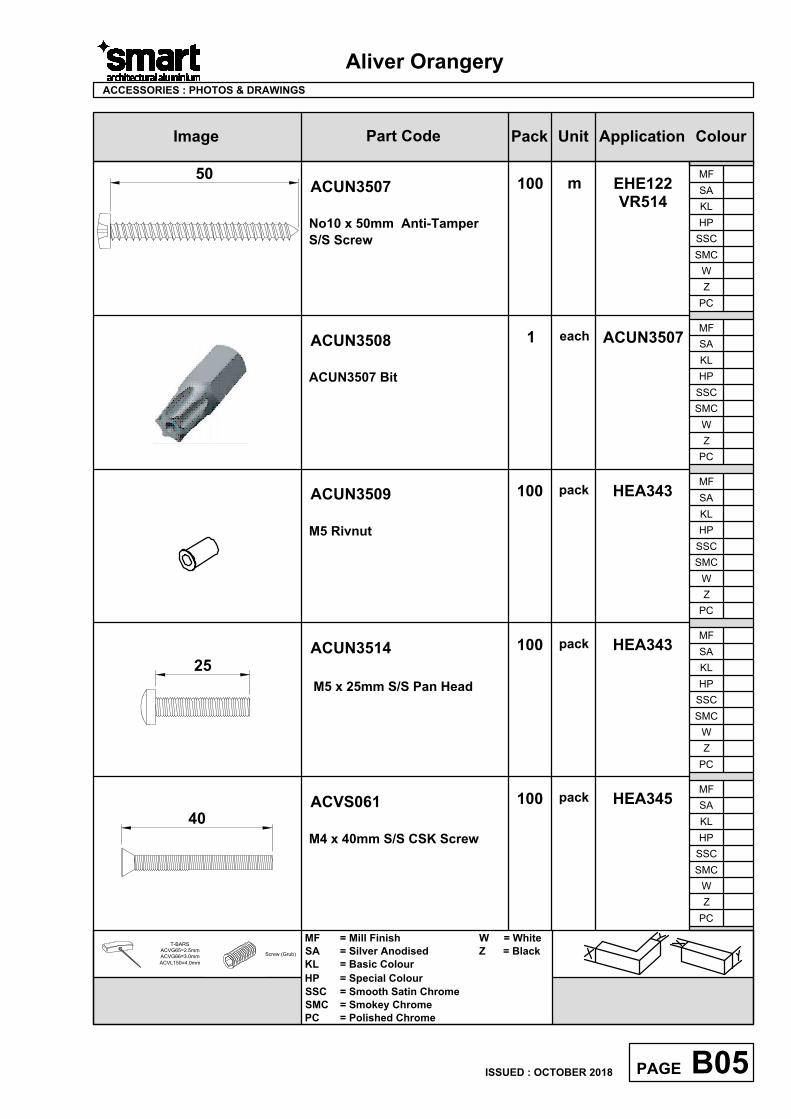
ACUN3507
No10 x 50mm Anti-Tamper
S/S Screw
100 m EHE122
VR514
50
ACUN3508
ACUN3507 Bit
1
each
ACUN3507
ACVS061
M4 x 40mm S/S CSK Screw
100
pack
40
HEA345
ACUN3509
M5 Rivnut
HEA343
ACUN3514
M5 x 25mm S/S Pan Head
100
pack
HEA343
100
pack
25
AutoCAD SHX Text
X
AutoCAD SHX Text
Y
AutoCAD SHX Text
X
AutoCAD SHX Text
Y
ColourImage Part Code Pack Unit Application
Aliver Orangery
B06PAGE
ACCESSORIES : PHOTOS & DRAWINGS
T-BARS
ACVG65=2.5mm
ACVG66=3.0mm
ACVL150=4.0mm
Screw (Grub)
MF = Mill Finish W = White
SA = Silver Anodised Z = Black
KL = Basic Colour
HP = Special Colour
SSC = Smooth Satin Chrome
SMC = Smokey Chrome
PC = Polished Chrome
ISSUED : OCTOBER 2018
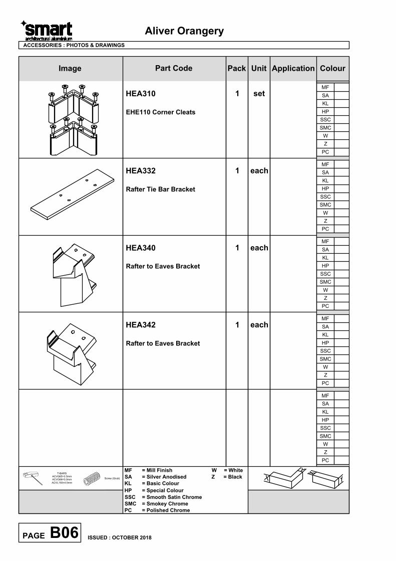
HEA310
EHE110 Corner Cleats
1 set
HEA342
Rafter to Eaves Bracket
1 each
HEA340
Rafter to Eaves Bracket
1 each
W
Z
PC
MF
SA
KL
HP
SSC
SMC
W
Z
PC
MF
SA
KL
HP
SSC
SMC
W
Z
PC
MF
SA
KL
HP
SSC
SMC
W
Z
PC
MF
SA
KL
HP
SSC
SMC
W
Z
PC
MF
SA
KL
HP
SSC
SMC
HEA332
Rafter Tie Bar Bracket
1 each
AutoCAD SHX Text
X
AutoCAD SHX Text
Y
AutoCAD SHX Text
X
AutoCAD SHX Text
Y
ColourImage Part Code Pack Unit Application
Aliver Orangery
B07PAGE
ACCESSORIES : PHOTOS & DRAWINGS
T-BARS
ACVG65=2.5mm
ACVG66=3.0mm
ACVL150=4.0mm
Screw (Grub)
W
Z
PC
MF
SA
KL
HP
SSC
SMC
W
Z
PC
MF
SA
KL
HP
SSC
SMC
W
Z
PC
MF
SA
KL
HP
SSC
SMC
W
Z
PC
MF
SA
KL
HP
SSC
SMC
MF = Mill Finish W = White
SA = Silver Anodised Z = Black
KL = Basic Colour
HP = Special Colour
SSC = Smooth Satin Chrome
SMC = Smokey Chrome
PC = Polished Chrome
ISSUED : OCTOBER 2018
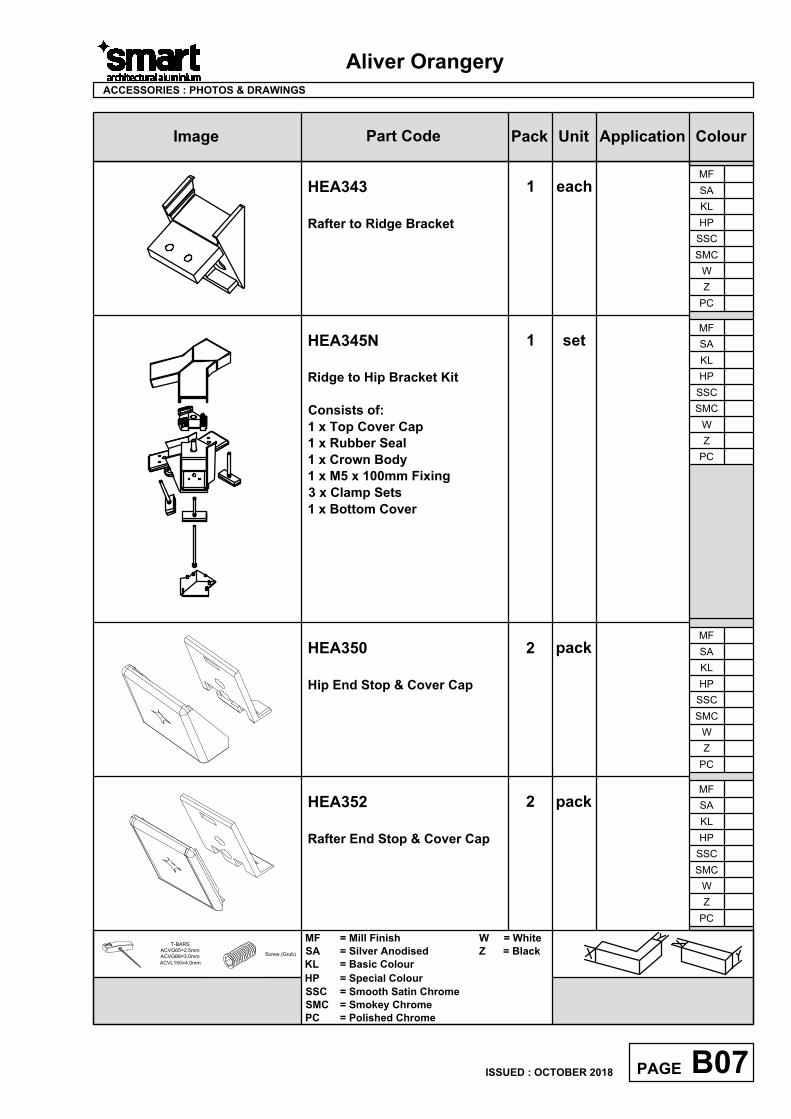
HEA352
Rafter End Stop & Cover Cap
2 pack
HEA350
Hip End Stop & Cover Cap
2 pack
HEA343
Rafter to Ridge Bracket
1 each
HEA345N
Ridge to Hip Bracket Kit
Consists of:
1 x Top Cover Cap
1 x Rubber Seal
1 x Crown Body
1 x M5 x 100mm Fixing
3 x Clamp Sets
1 x Bottom Cover
1 set
AutoCAD SHX Text
X
AutoCAD SHX Text
Y
AutoCAD SHX Text
X
AutoCAD SHX Text
Y
ColourImage Part Code Pack Unit Application
Aliver Orangery
B08PAGE
ACCESSORIES : PHOTOS & DRAWINGS
T-BARS
ACVG65=2.5mm
ACVG66=3.0mm
ACVL150=4.0mm
Screw (Grub)
W
Z
PC
MF
SA
KL
HP
SSC
SMC
MF = Mill Finish W = White
SA = Silver Anodised Z = Black
KL = Basic Colour
HP = Special Colour
SSC = Smooth Satin Chrome
SMC = Smokey Chrome
PC = Polished Chrome
ISSUED : OCTOBER 2018
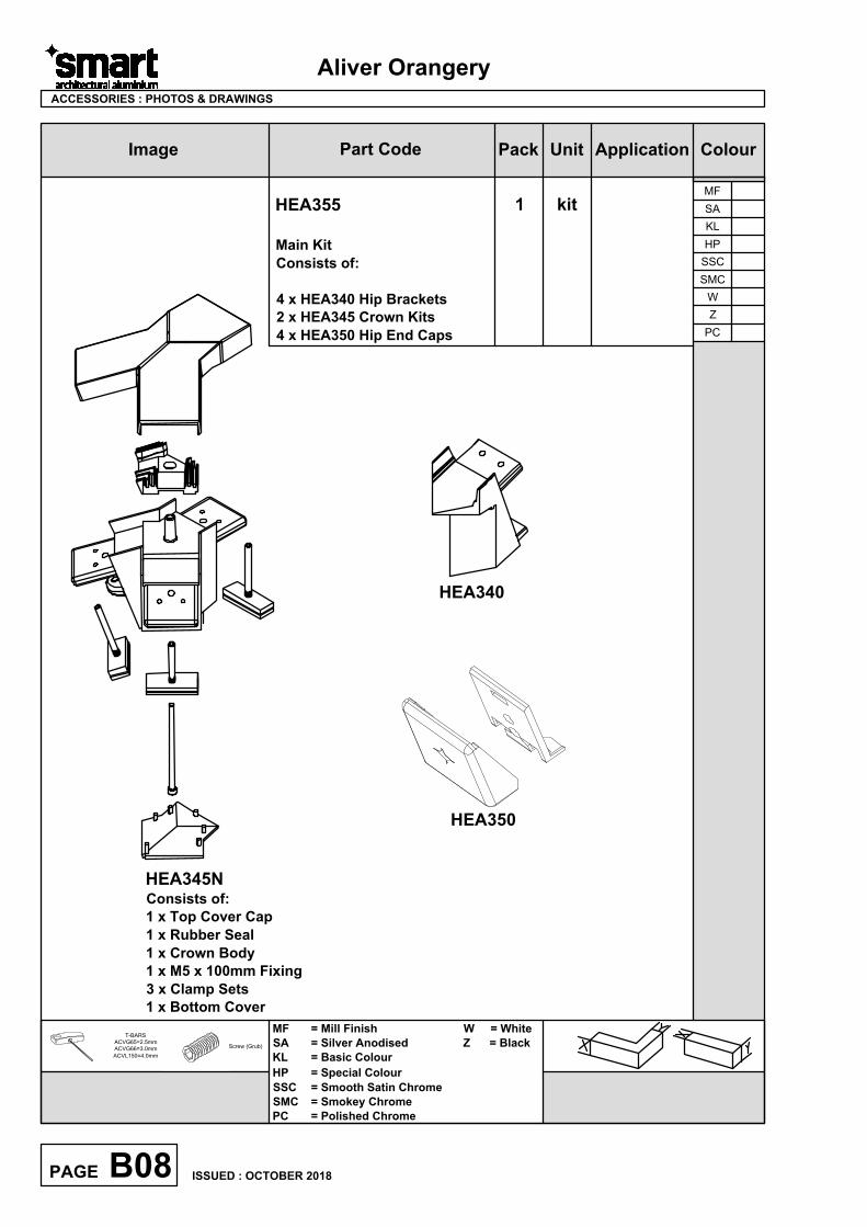
HEA355
Main Kit
Consists of:
4 x HEA340 Hip Brackets
2 x HEA345 Crown Kits
4 x HEA350 Hip End Caps
HEA345N
Consists of:
1 x Top Cover Cap
1 x Rubber Seal
1 x Crown Body
1 x M5 x 100mm Fixing
3 x Clamp Sets
1 x Bottom Cover
HEA340
1 kit
HEA350
AutoCAD SHX Text
X
AutoCAD SHX Text
Y
AutoCAD SHX Text
X
AutoCAD SHX Text
Y
ColourImage Part Code Pack Unit Application
Aliver Orangery
B09PAGE
ACCESSORIES : PHOTOS & DRAWINGS
T-BARS
ACVG65=2.5mm
ACVG66=3.0mm
ACVL150=4.0mm
Screw (Grub)
W
Z
PC
MF
SA
KL
HP
SSC
SMC
MF = Mill Finish W = White
SA = Silver Anodised Z = Black
KL = Basic Colour
HP = Special Colour
SSC = Smooth Satin Chrome
SMC = Smokey Chrome
PC = Polished Chrome
ISSUED : OCTOBER 2018
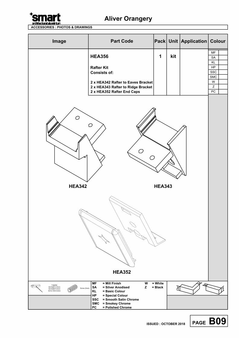
HEA356
Rafter Kit
Consists of:
2 x HEA342 Rafter to Eaves Bracket
2 x HEA343 Rafter to Ridge Bracket
2 x HEA352 Rafter End Caps
1 kit
HEA342 HEA343
HEA352
AutoCAD SHX Text
X
AutoCAD SHX Text
Y
AutoCAD SHX Text
X
AutoCAD SHX Text
Y
ColourImage Part Code Pack Unit Application
Aliver Orangery
B10PAGE
ACCESSORIES : PHOTOS & DRAWINGS
T-BARS
ACVG65=2.5mm
ACVG66=3.0mm
ACVL150=4.0mm
Screw (Grub)
W
Z
PC
MF
SA
KL
HP
SSC
SMC
W
Z
PC
MF
SA
KL
HP
SSC
SMC
W
Z
PC
MF
SA
KL
HP
SSC
SMC
W
Z
PC
MF
SA
KL
HP
SSC
SMC
W
Z
PC
MF
SA
KL
HP
SSC
SMC
MF = Mill Finish W = White
SA = Silver Anodised Z = Black
KL = Basic Colour
HP = Special Colour
SSC = Smooth Satin Chrome
SMC = Smokey Chrome
PC = Polished Chrome
ISSUED : OCTOBER 2018
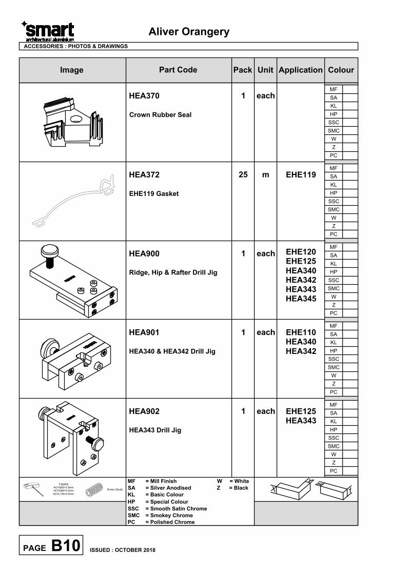
HEA900
Ridge, Hip & Rafter Drill Jig
1 each
EHE120
EHE125
HEA340
HEA342
HEA343
HEA345
HEA901
HEA340 & HEA342 Drill Jig
1 each EHE110
HEA340
HEA342
HEA902
HEA343 Drill Jig
1 each EHE125
HEA343
HEA372
EHE119 Gasket
25 m
HEA370
Crown Rubber Seal
1 each
EHE119
AutoCAD SHX Text
X
AutoCAD SHX Text
Y
AutoCAD SHX Text
X
AutoCAD SHX Text
Y
ColourImage Part Code Pack Unit Application
Aliver Orangery
ACCESSORIES : PHOTOS & DRAWINGS
T-BARS
ACVG65=2.5mm
ACVG66=3.0mm
ACVL150=4.0mm
Screw (Grub)
W
Z
PC
MF
SA
KL
HP
SSC
SMC
W
Z
PC
MF
SA
KL
HP
SSC
SMC
W
Z
PC
MF
SA
KL
HP
SSC
SMC
W
Z
PC
MF
SA
KL
HP
SSC
SMC
W
Z
PC
MF
SA
KL
HP
SSC
SMC
MF = Mill Finish W = White
SA = Silver Anodised Z = Black
KL = Basic Colour
HP = Special Colour
SSC = Smooth Satin Chrome
SMC = Smokey Chrome
PC = Polished Chrome
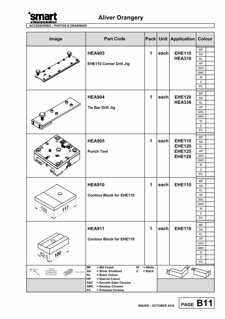
HEA903
EHE110 Corner Drill Jig
1 each EHE110
HEA310
B11PAGE
ISSUED : OCTOBER 2018
HEA904
Tie Bar Drill Jig
1 each EHE120
HEA336
1
0
06
2
.
5
1
1
71
0
0
HEA910
Contour Block for EHE110
1 each EHE110
HEA911
Contour Block for EHE119
1 each EHE119
HEA905
Punch Tool
1 each EHE110
EHE120
EHE125
EHE128
AutoCAD SHX Text
X
AutoCAD SHX Text
Y
AutoCAD SHX Text
X
AutoCAD SHX Text
Y
ColourImage Part Code Pack Unit Application
Aliver Orangery
ACCESSORIES : PHOTOS & DRAWINGS
T-BARS
ACVG65=2.5mm
ACVG66=3.0mm
ACVL150=4.0mm
Screw (Grub)
W
Z
PC
MF
SA
KL
HP
SSC
SMC
W
Z
PC
MF
SA
KL
HP
SSC
SMC
W
Z
PC
MF
SA
KL
HP
SSC
SMC
W
Z
PC
MF
SA
KL
HP
SSC
SMC
W
Z
PC
MF
SA
KL
HP
SSC
SMC
MF = Mill Finish W = White
SA = Silver Anodised Z = Black
KL = Basic Colour
HP = Special Colour
SSC = Smooth Satin Chrome
SMC = Smokey Chrome
PC = Polished Chrome
B12PAGE
ISSUED : OCTOBER 2018
üACMX09700 1 each
Alu-Polish
Cleaning emulsion for
aluminium oxide.
ACMX09761 1 each
Maxi Gloss
Protection for painted and
anodised surfaces.
ACMX09762 1 each
Alu. Bright
Cleaner for rough,
anodised or enamelled
aluminium frames.
ACMX09763 1 each
Teflon Spray
Lubricant
WCA143
M5 x 25mm Screw
100 pack HEA340
HEA342
HEA343
HEA345
25
AutoCAD SHX Text
X
AutoCAD SHX Text
Y
AutoCAD SHX Text
X
AutoCAD SHX Text
Y
Aliver Orangery
ColourImage Part Code Pack Unit Application ColourImage Part Code Pack Unit Application
ACCESSORIES : PHOTOS & DRAWINGS
T-BARS
ACVG65=2.5mm
ACVG66=3.0mm
ACVL150=4.0mm
Screw (Grub)
W
Z
PC
MF
SA
KL
HP
SSC
SMC
W
Z
PC
MF
SA
KL
HP
SSC
SMC
W
Z
PC
MF
SA
KL
HP
SSC
SMC
W
Z
PC
MF
SA
KL
HP
SSC
SMC
W
Z
PC
MF
SA
KL
HP
SSC
SMC
MF = Mill Finish W = White
SA = Silver Anodised Z = Black
KL = Basic Colour
HP = Special Colour
SSC = Smooth Satin Chrome
SMC = Smokey Chrome
PC = Polished Chrome
B13PAGE
ISSUED : OCTOBER 2018
ACMX09764 1 each
Maxi Cleaner
For cleaning oily surfaces.
ACMX09765 1 each
Glue Cleaner
De-grease and silicone
remover.
ACMX09770 1 each
Roll & Wrap 100mm
ACMX09775 1 each
Grip Handwrap
ACMX09801 1 each
Protective Tape 50mm
AutoCAD SHX Text
X
AutoCAD SHX Text
Y
AutoCAD SHX Text
X
AutoCAD SHX Text
Y
Aliver Orangery
ColourImage Part Code Pack Unit Application
ACCESSORIES : PHOTOS & DRAWINGS
T-BARS
ACVG65=2.5mm
ACVG66=3.0mm
ACVL150=4.0mm
Screw (Grub)
W
Z
PC
MF
SA
KL
HP
SSC
SMC
W
Z
PC
MF
SA
KL
HP
SSC
SMC
W
Z
PC
MF
SA
KL
HP
SSC
SMC
W
Z
PC
MF
SA
KL
HP
SSC
SMC
W
Z
PC
MF
SA
KL
HP
SSC
SMC
MF = Mill Finish W = White
SA = Silver Anodised Z = Black
KL = Basic Colour
HP = Special Colour
SSC = Smooth Satin Chrome
SMC = Smokey Chrome
PC = Polished Chrome
B14PAGE
ISSUED : OCTOBER 2018
üü
ü
ACMX09802 1 each
Protective Tape 70mm
ACMX09803 1 each
Protective Tape 100mm
ACSIL05 1 each
Rubber Sealant
ACSIL04 1 each
Sealing Glue
Order with suffix of KL
colour (eg.ACSIL04KL005)
or BL=Black/WP=White/
CL=Clear
ACSIL08 1 each
Silicon Gun
AutoCAD SHX Text
X
AutoCAD SHX Text
Y
AutoCAD SHX Text
X
AutoCAD SHX Text
Y
Aliver Orangery
ColourImage Part Code Pack Unit Application
ACCESSORIES : PHOTOS & DRAWINGS
T-BARS
ACVG65=2.5mm
ACVG66=3.0mm
ACVL150=4.0mm
Screw (Grub)
W
Z
PC
MF
SA
KL
HP
SSC
SMC
W
Z
PC
MF
SA
KL
HP
SSC
SMC
W
Z
PC
MF
SA
KL
HP
SSC
SMC
W
Z
PC
MF
SA
KL
HP
SSC
SMC
W
Z
PC
MF
SA
KL
HP
SSC
SMC
MF = Mill Finish W = White
SA = Silver Anodised Z = Black
KL = Basic Colour
HP = Special Colour
SSC = Smooth Satin Chrome
SMC = Smokey Chrome
PC = Polished Chrome
ACSIL013 1 each
Glue for Mitre
ACSIL014 1 each
Anti-Corrosion Coating
ü
ACUN3900
Gasket Roller
1 each
ACUN3610
Single Component
Adhesive
1 each
ACUN3612
Surface Activator (1L)
1 each
B15PAGE
ISSUED : OCTOBER 2018
AutoCAD SHX Text
X
AutoCAD SHX Text
Y
AutoCAD SHX Text
X
AutoCAD SHX Text
Y
Aliver Orangery
ColourImage Part Code Pack Unit Application
ACCESSORIES : PHOTOS & DRAWINGS
T-BARS
ACVG65=2.5mm
ACVG66=3.0mm
ACVL150=4.0mm
Screw (Grub)
W
Z
PC
MF
SA
KL
HP
SSC
SMC
W
Z
PC
MF
SA
KL
HP
SSC
SMC
W
Z
PC
MF
SA
KL
HP
SSC
SMC
W
Z
PC
MF
SA
KL
HP
SSC
SMC
W
Z
PC
MF
SA
KL
HP
SSC
SMC
MF = Mill Finish W = White
SA = Silver Anodised Z = Black
KL = Basic Colour
HP = Special Colour
SSC = Smooth Satin Chrome
SMC = Smokey Chrome
PC = Polished Chrome
B16PAGE
ISSUED : OCTOBER 2018
AutoCAD SHX Text
X
AutoCAD SHX Text
Y
AutoCAD SHX Text
X
AutoCAD SHX Text
Y
Sections
Scale Elevations
Aliver Orangery
Section C
C01PAGE
ISSUED : OCTOBER 2018
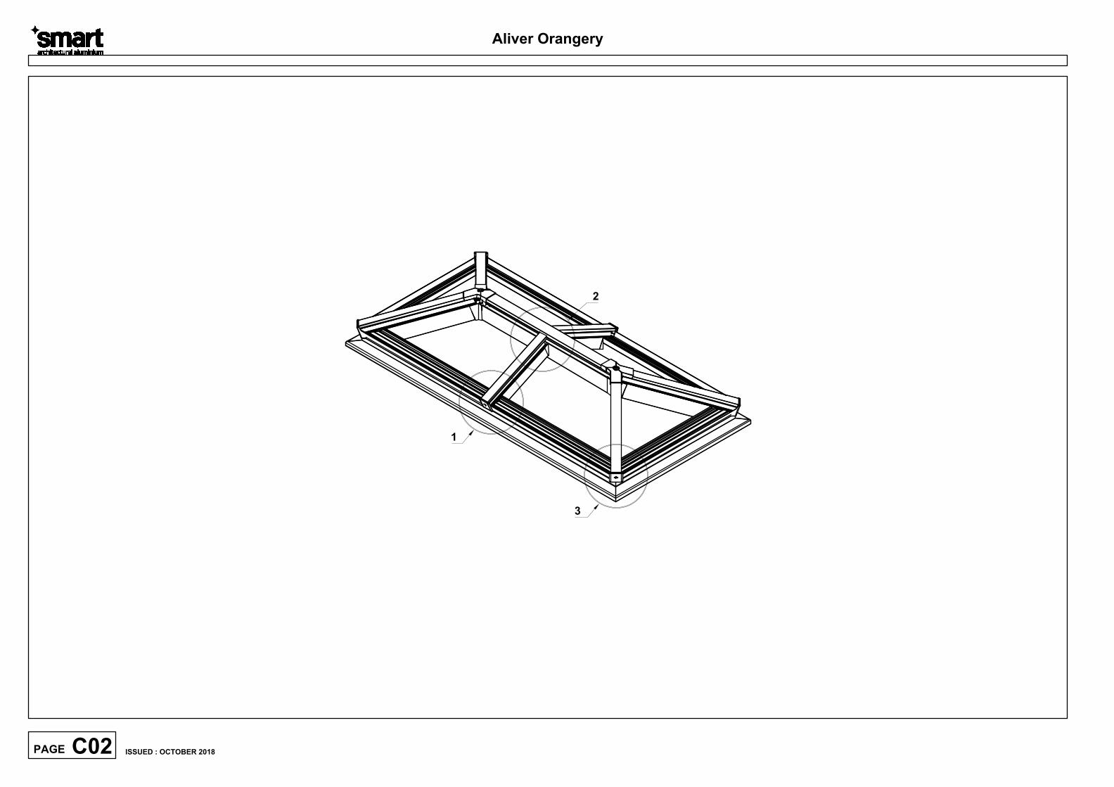
1
2
3
Aliver Orangery
C02PAGE
ISSUED : OCTOBER 2018
Do Not Scale From This Drawing
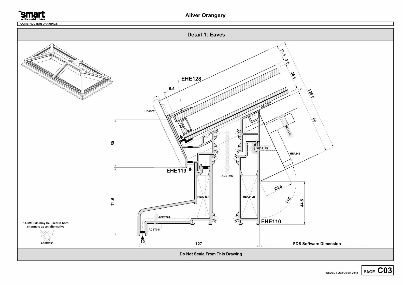
Detail 1: Eaves
Aliver Orangery
CONSTRUCTION DRAWINGS
H
E
A
3
7
2
*
EHE110
EHE119
HEA342
127
71
.5
50
10
2
9
.
5
1
1
5
°
HEA310A HEA310B
ACET041
ACET064
HEA352
EHE128
6
8
3
2
8
.
5
1
7
.
5
3
.
5
1
2
0
.
5
6.5
44
.5
C03PAGE
ISSUED : OCTOBER 2018
WCA143
W
C
A
1
4
3
FDS Software Dimension
ACET190
*ACMC635 may be used in both
channels as an alternative
ACMC635
Do Not Scale From This Drawing
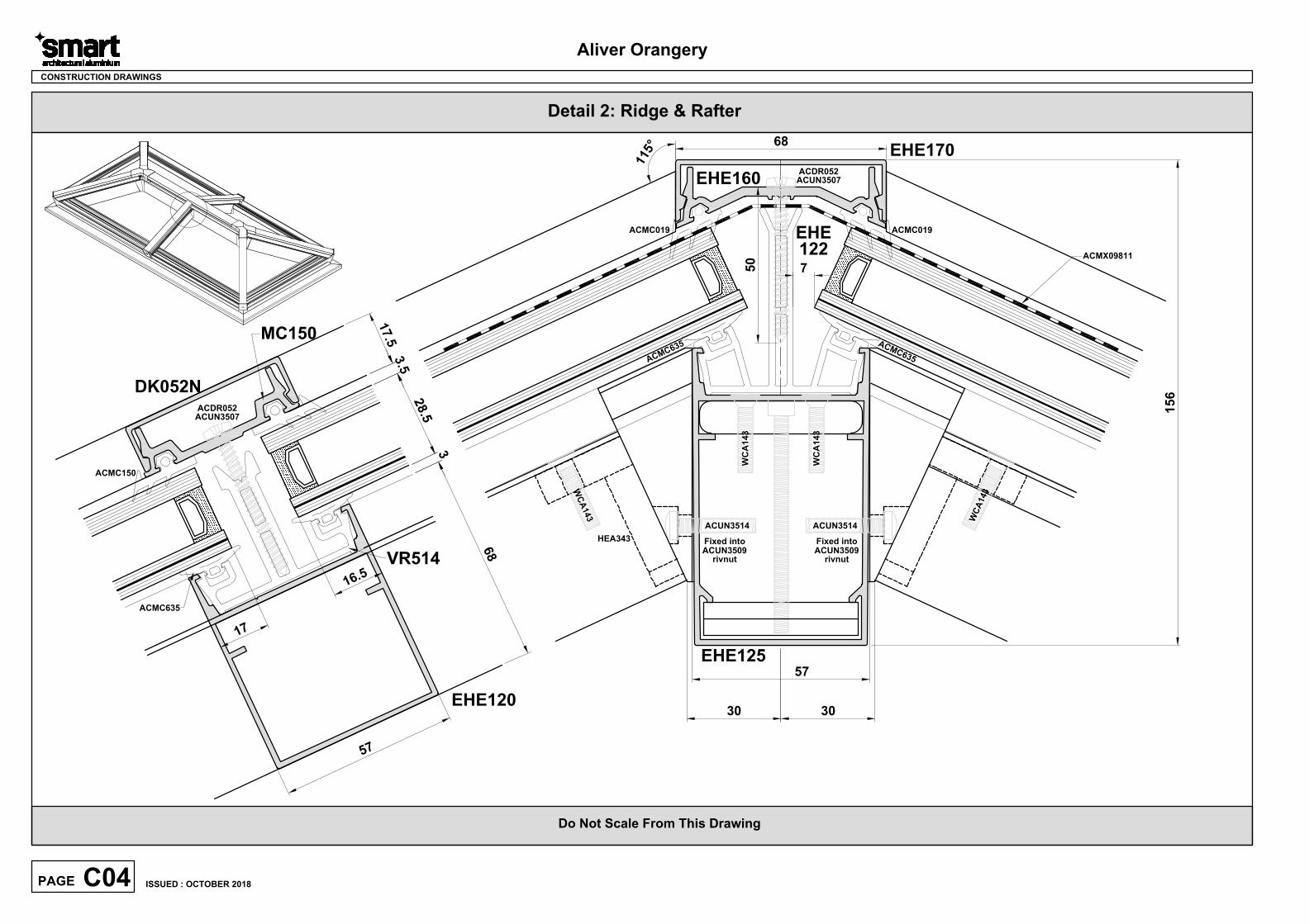
Detail 2: Ridge & Rafter
CONSTRUCTION DRAWINGS
DK052N
MC150
EHE120
1
6
.
5
1
7
5
7
ACMC150
EHE160
EHE170
EHE125
68
57
ACMC019
ACUN3507
EHE
122
VR514
6
8
2
8
.
5
1
7
.
5
15
6
7
30 30
1
1
5
°
HEA343
ACMC635
C04PAGE
ISSUED : OCTOBER 2018
Aliver Orangery
50
A
C
M
C
6
3
5
ACDR052
W
C
A
1
4
3
W
C
A
1
4
3
WC
A1
43
WC
A1
43
A
C
M
C
6
3
5
3
3
.
5
ACMC019
ACMX09811
ACUN3507
ACDR052
ACUN3514
rivnut
Fixed into
ACUN3509
Fixed into
ACUN3509
rivnut
ACUN3514
Do Not Scale From This Drawing
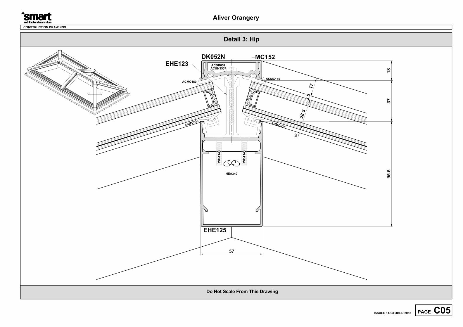
Detail 3: Hip
CONSTRUCTION DRAWINGS
EHE125
57
DK052NMC152
95
.5
37
18
HEA340
C05PAGE
ISSUED : OCTOBER 2018
Aliver Orangery
ACUN3507
ACDR052
WC
A1
43
WC
A1
43
EHE123
A
C
M
C
6
3
5
A
C
M
C
6
3
5
ACMC150
ACMC150
2
8
.5
3
1
7
3
.5

Do Not Scale From This Drawing
CONSTRUCTION DRAWINGS
C06PAGE
ISSUED : OCTOBER 2018
Aliver Orangery
Aliver Orangery
Section D
D01PAGE
ISSUED : OCTOBER 2018
General Size Limitations are shown on Page A03.
For Wind Loading Limitations, Please Contact
The Technical Department - T: 01934 833100
Statics
Aliver Orangery
D02PAGE
ISSUED : OCTOBER 2018
Aliver Orangery
Section E
E01PAGE
Construction Drawings
EHE119 Corner Detail...................................................................... E03
HEA905 Punch Tool......................................................................... E04
Hip to Eaves Assembly....................................................................
E05
HEA350 Hip End Cap.......................................................................
E06
Ridge & Hip Assembly.....................................................................
E07
Crown Assembly..............................................................................
E08
Rafter to Ridge Assembly...............................................................E09
Rafter to Eaves Assembly...............................................................
E10
HEA352 Rafter End Cap...................................................................
E11
EHE128 Glass End Cover................................................................ E12
Typical Installation Details..............................................................
E13 - E14
Tie Bar Details.................................................................................. E15
EEHE
ISSUED : OCTOBER 2018

Aliver Orangery
E02PAGE
ISSUED : OCTOBER 2018
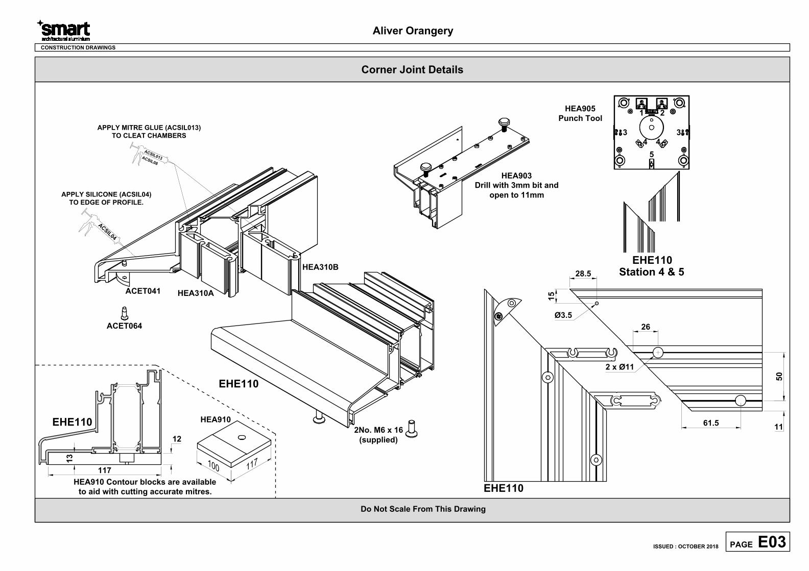
Corner Joint Details
Do Not Scale From This Drawing
CONSTRUCTION DRAWINGS
26
2 x Ø11
61.5
50
11
Ø3.5
15
28.5
HEA310A
EHE110
HEA310B
2No. M6 x 16
(supplied)
ACET041
ACET064
A
C
S
I
L
0
4
APPLY MITRE GLUE (ACSIL013)
TO CLEAT CHAMBERS
A
C
S
I
L
0
1
3
A
C
S
I
L
0
8
APPLY SILICONE (ACSIL04)
TO EDGE OF PROFILE.
Aliver Orangery
E03PAGE
ISSUED : OCTOBER 2018
HEA903
Drill with 3mm bit and
open to 11mm
EHE110
HEA910 Contour blocks are available
to aid with cutting accurate mitres.
HEA910
12
117
EHE110
13
1
1
71
0
0
5
4 4
3 3
1
HEA905
Punch Tool
EHE110
2
Station 4 & 5
Do Not Scale From This Drawing
CONSTRUCTION DRAWINGS
Aliver Orangery
E04PAGE
ISSUED : OCTOBER 2018
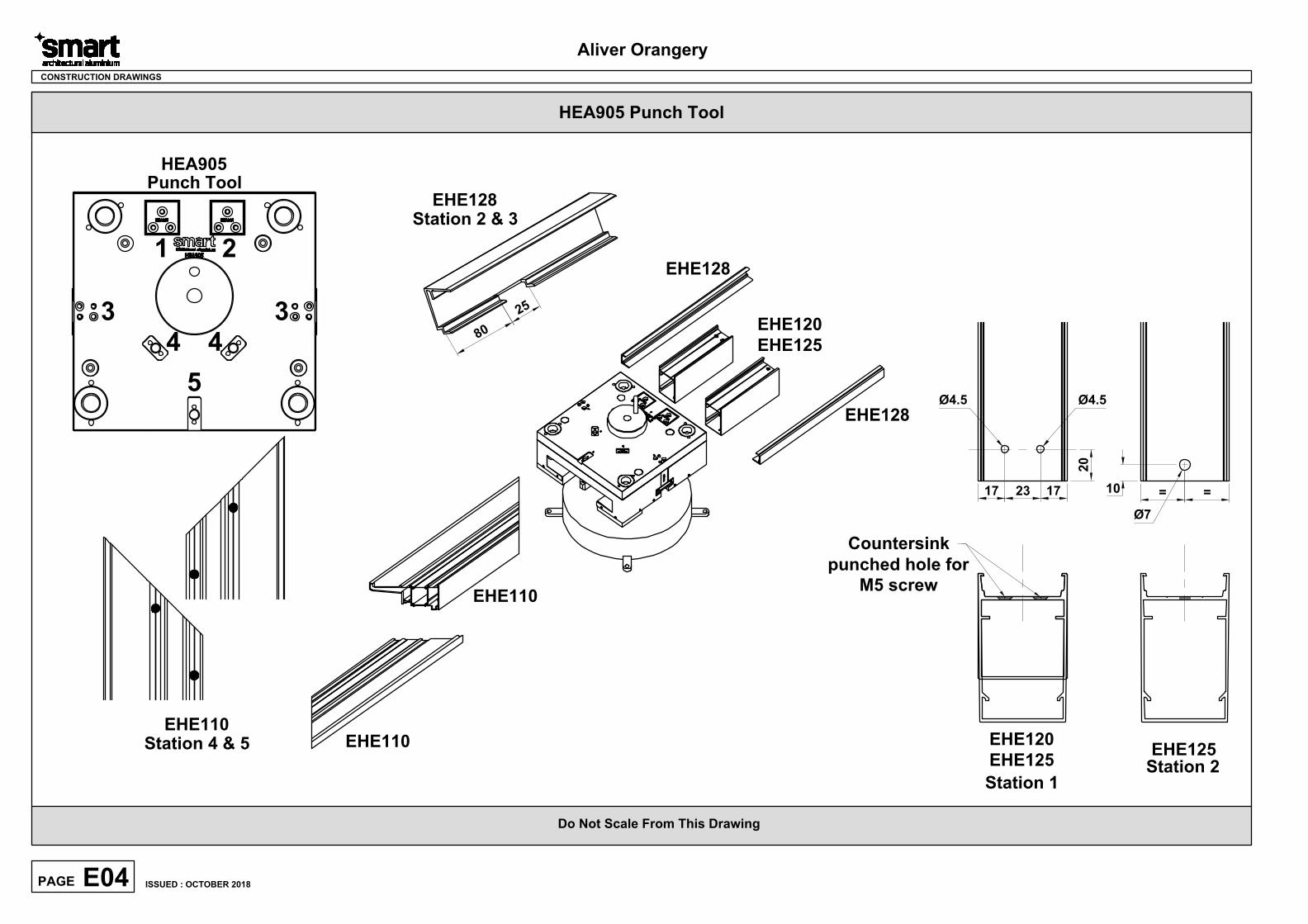
HEA905 Punch Tool
5
4 4
3 3
1
HEA905
Punch Tool
EHE110
EHE110
EHE110
EHE128
EHE128
EHE120
EHE125
8
0
2
5
EHE128
20
23 1717
EHE120
EHE125
Station 4 & 5
Station 2 & 3
Station 1
Countersink
punched hole for
M5 screw
Ø4.5
EHE125
Ø7
Station 2
10
= =
Ø4.5
2
Do Not Scale From This Drawing
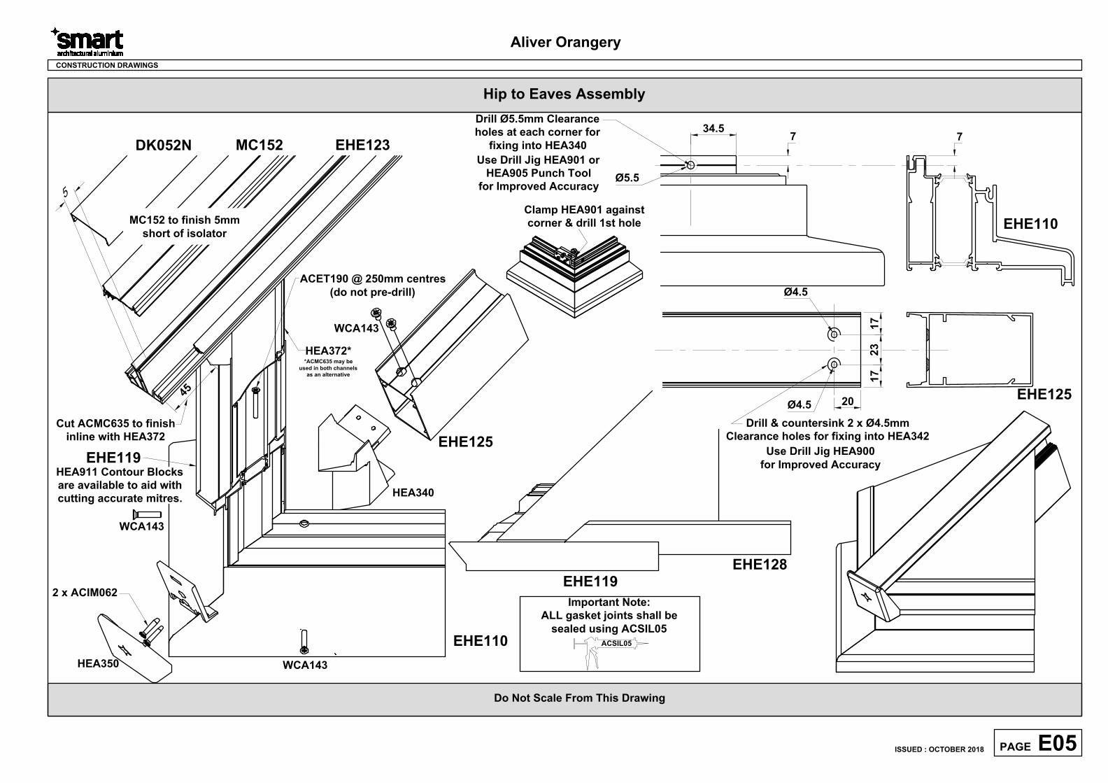
Hip to Eaves Assembly
CONSTRUCTION DRAWINGS
7
20
23
17
17
Ø4.5
Ø4.5
Drill & countersink 2 x Ø4.5mm
Clearance holes for fixing into HEA342
EHE125
EHE110
Drill Ø5.5mm Clearance
holes at each corner for
fixing into HEA340
34.5
7
Ø5.5
Use Drill Jig HEA900
for Improved Accuracy
Aliver Orangery
E05PAGE
ISSUED : OCTOBER 2018
Use Drill Jig HEA901 or
HEA905 Punch Tool
for Improved Accuracy
Clamp HEA901 against
corner & drill 1st hole
EHE119
EHE128
EHE123DK052N MC152
EHE110
HEA350
2 x ACIM062
HEA340
WCA143
EHE125
EHE119
ACET190 @ 250mm centres
(do not pre-drill)
HEA372*
4
5
Cut ACMC635 to finish
inline with HEA372
WCA143
WCA143
ACSIL05
Important Note:
ALL gasket joints shall be
sealed using ACSIL05
5
MC152 to finish 5mm
short of isolator
HEA911 Contour Blocks
are available to aid with
cutting accurate mitres.
*ACMC635 may be
used in both channels
as an alternative
Do Not Scale From This Drawing
CONSTRUCTION DRAWINGS
Aliver Orangery
E06PAGE
ISSUED : OCTOBER 2018
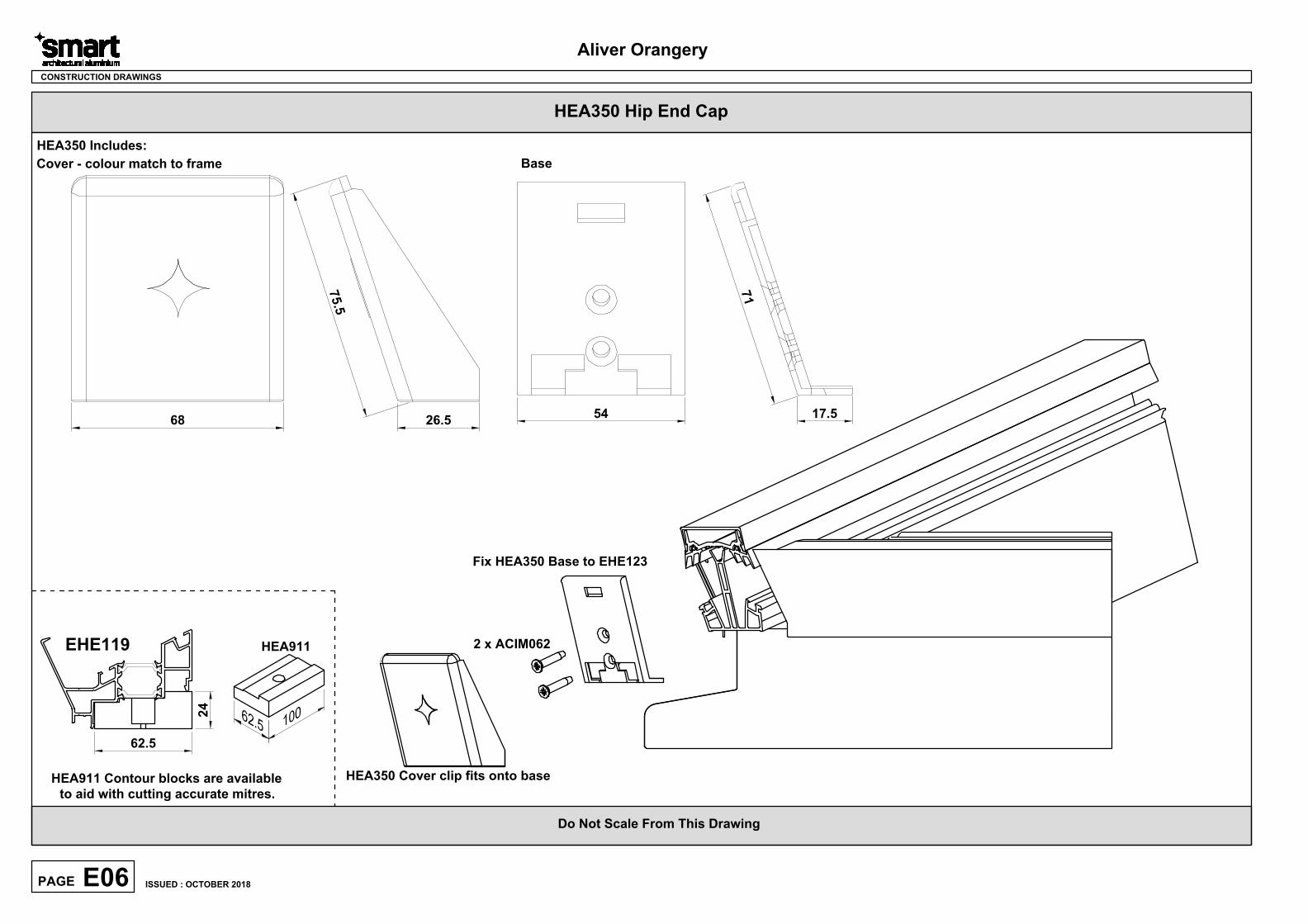
68 26.5
7
5
.
5
HEA350 Includes:
7
1
54
Cover - colour match to frame Base
17.5
2 x ACIM062
Fix HEA350 Base to EHE123
HEA350 Cover clip fits onto base
HEA350 Hip End Cap
HEA911 Contour blocks are available
to aid with cutting accurate mitres.
HEA911EHE119
62.5
1
0
06
2
.
5
24
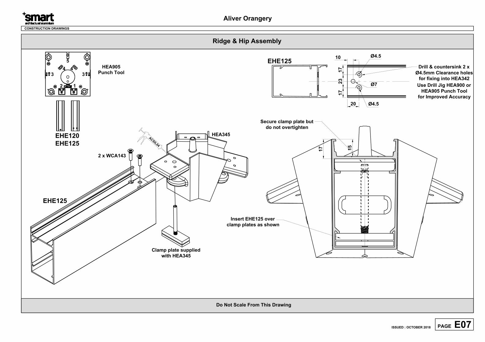
CONSTRUCTION DRAWINGS
20
23
17
17
Ø4.5
Ø4.5
Drill & countersink 2 x
Ø4.5mm Clearance holes
for fixing into HEA342
EHE125
Use Drill Jig HEA900 or
HEA905 Punch Tool
for Improved Accuracy
Aliver Orangery
E07PAGE
ISSUED : OCTOBER 2018
Ø7
10
A
C
S
I
L
0
4
HEA345
EHE125
2 x WCA143
Insert EHE125 over
clamp plates as shown
Clamp plate supplied
with HEA345
Ridge & Hip Assembly
Secure clamp plate but
do not overtighten
17
15
Do Not Scale From This Drawing
EHE120
EHE125
HEA905
Punch Tool
5
4
3
12
3
4
Do Not Scale From This Drawing
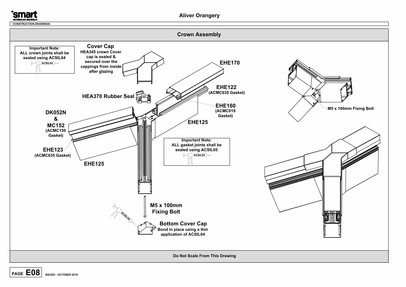
Crown Assembly
CONSTRUCTION DRAWINGS
Aliver Orangery
E08PAGE
ISSUED : OCTOBER 2018
ACSIL04
Important Note:
ALL crown joints shall be
sealed using ACSIL04
EHE125
EHE122
EHE170
(ACMC635 Gasket)
EHE160
(ACMC019
Gasket)
EHE125
DK052N
&
MC152
(ACMC150
Gasket)
EHE123
(ACMC635 Gasket)
A
C
S
I
L
0
4
ACSIL05
Important Note:
ALL gasket joints shall be
sealed using ACSIL05
M5 x 100mm Fixing Bolt
HEA370 Rubber Seal
Bottom Cover Cap
Bond in place using a thin
application of ACSIL04
M5 x 100mm
Fixing Bolt
Cover Cap
HEA345 crown Cover
cap is sealed &
secured over the
cappings from inside
after glazing
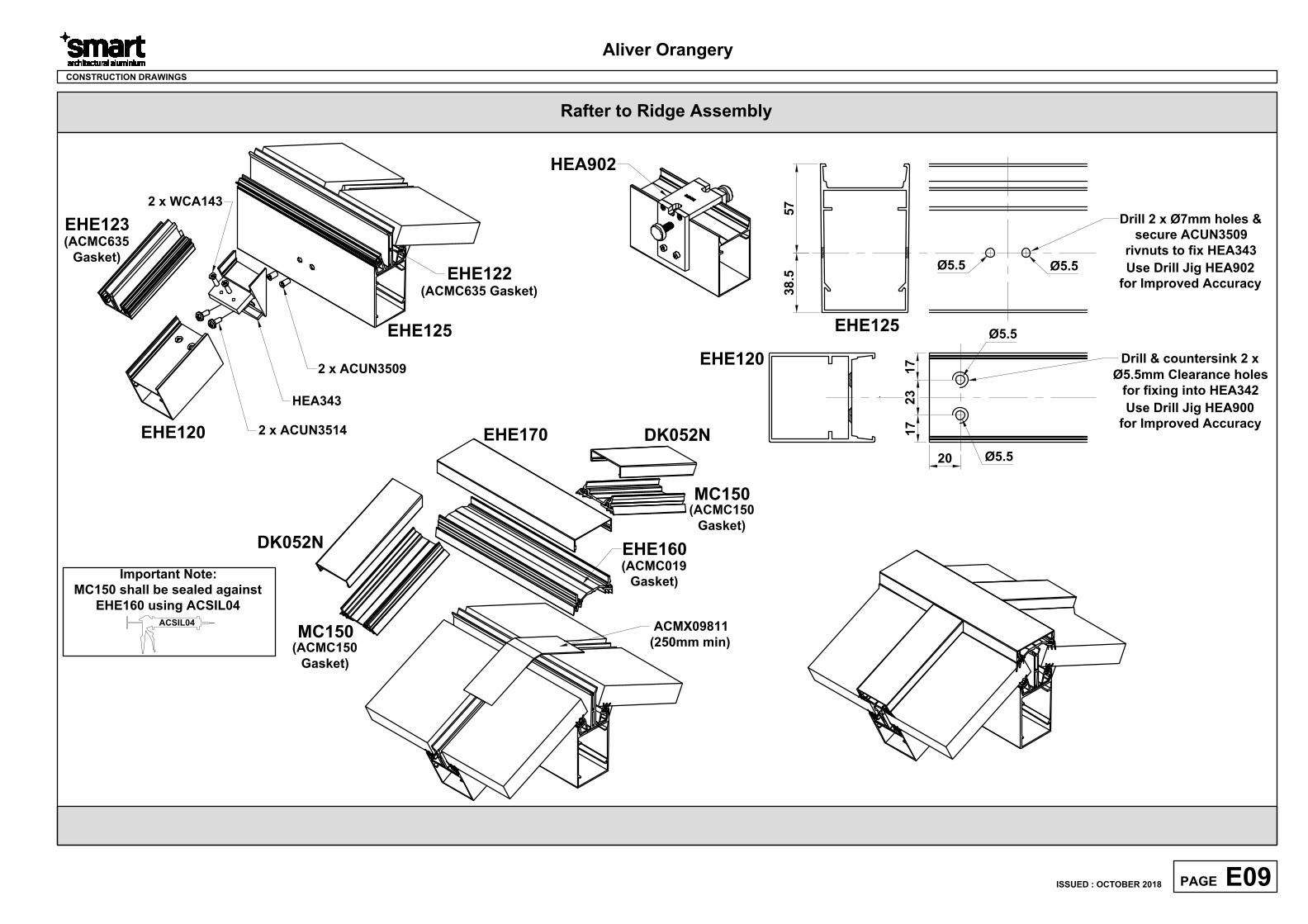
Rafter to Ridge Assembly
CONSTRUCTION DRAWINGS
DK052N
Aliver Orangery
E09PAGE
ISSUED : OCTOBER 2018
38
.5
Ø5.5Ø5.5
EHE125
Drill 2 x Ø7mm holes &
secure ACUN3509
rivnuts to fix HEA343
57
20
23
17
17
Ø5.5
Ø5.5
Drill & countersink 2 x
Ø5.5mm Clearance holes
for fixing into HEA342
EHE120
Use Drill Jig HEA900
for Improved Accuracy
Use Drill Jig HEA902
for Improved Accuracy
HEA902
EHE170
EHE160
EHE125
2 x ACUN3509
HEA343
EHE120
EHE123
2 x ACUN3514
2 x WCA143
DK052N
MC150
ACMX09811
(250mm min)
EHE122
(ACMC635 Gasket)
(ACMC635
Gasket)
(ACMC150
Gasket)
MC150
(ACMC150
Gasket)
(ACMC019
Gasket)
ACSIL04
Important Note:
MC150 shall be sealed against
EHE160 using ACSIL04
Do Not Scale From This Drawing
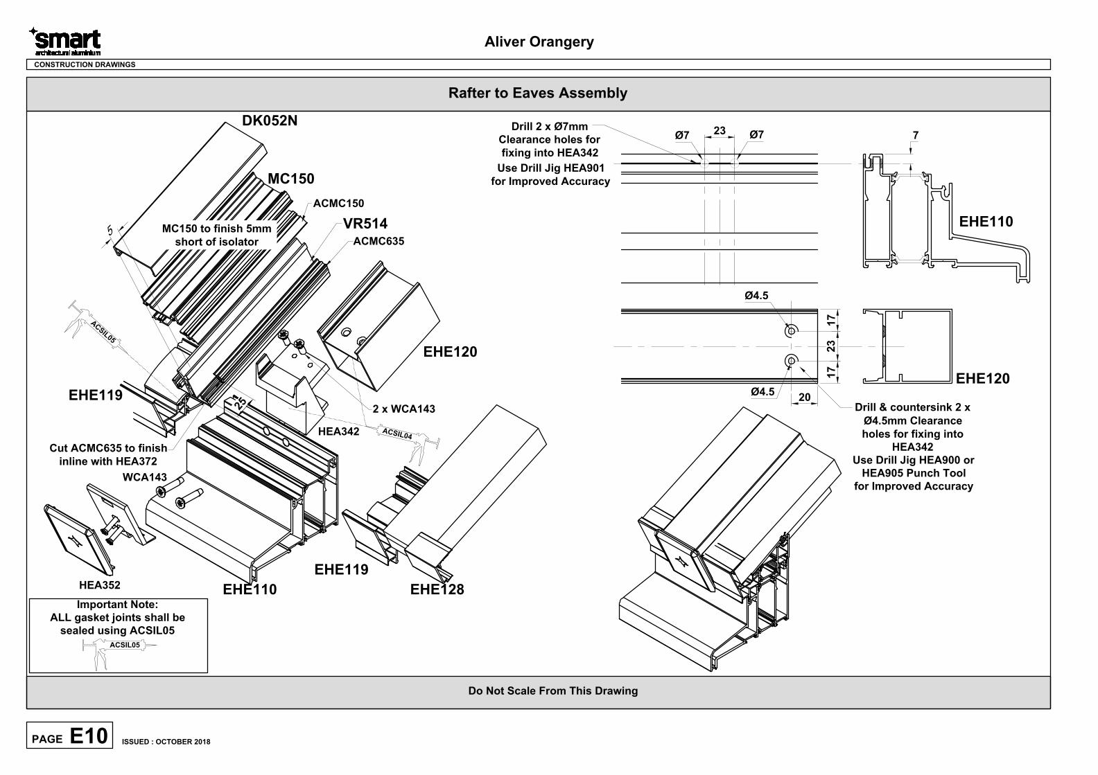
Rafter to Eaves Assembly
CONSTRUCTION DRAWINGS
EHE110
EHE119
EHE119
HEA352
HEA342
EHE120
DK052N
MC150
VR514
ACMC150
ACMC635
7
23
Ø7Ø7
Drill 2 x Ø7mm
Clearance holes for
fixing into HEA342
20
23
17
17
Ø4.5
Drill & countersink 2 x
Ø4.5mm Clearance
holes for fixing into
HEA342
EHE120
EHE110
EHE128
Use Drill Jig HEA900 or
HEA905 Punch Tool
for Improved Accuracy
Aliver Orangery
E10PAGE
ISSUED : OCTOBER 2018
Use Drill Jig HEA901
for Improved Accuracy
WCA143
2 x WCA143
2
5
Cut ACMC635 to finish
inline with HEA372
ACSIL05
Important Note:
ALL gasket joints shall be
sealed using ACSIL05
A
C
S
I
L
0
5
A
C
S
IL
0
4
5
MC150 to finish 5mm
short of isolator
Ø4.5
Do Not Scale From This Drawing
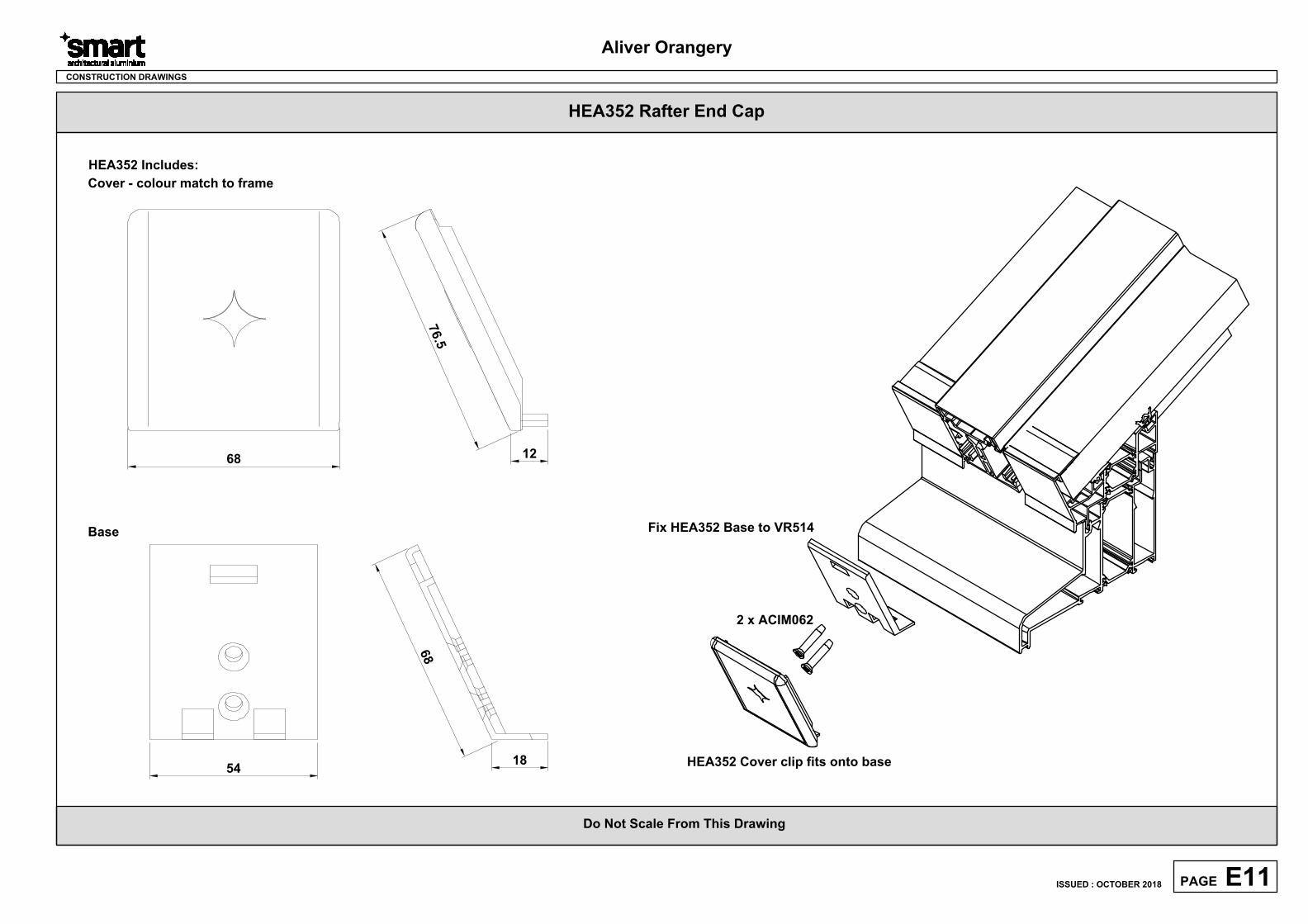
Aliver Orangery
E11PAGE
CONSTRUCTION DRAWINGS
2 x ACIM062
Fix HEA352 Base to VR514
HEA352 Cover clip fits onto base
68
HEA352 Includes:
Cover - colour match to frame
Base
7
6
.
5
12
54
18
6
8
HEA352 Rafter End Cap
ISSUED : OCTOBER 2018
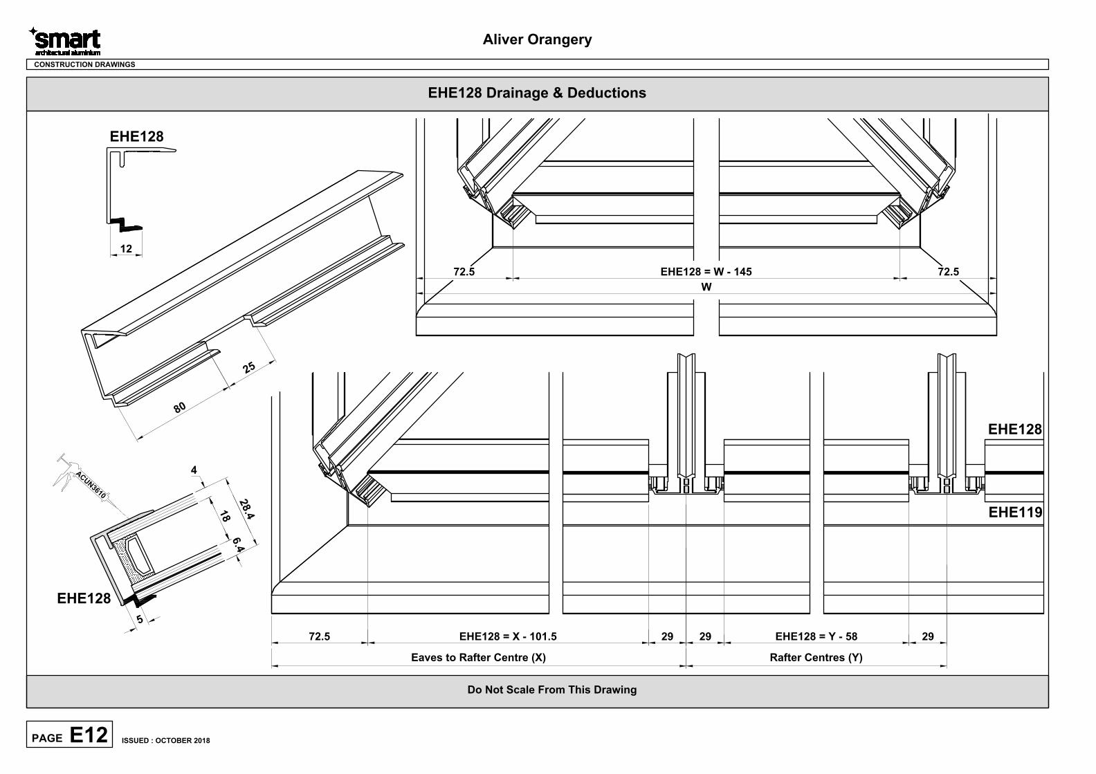
Do Not Scale From This Drawing
EHE128 Drainage & Deductions
Aliver Orangery
E12PAGE
CONSTRUCTION DRAWINGS
8
0
2
5
12
EHE128
A
C
U
N
3
6
1
0
2
8
.
4
4
6
.
4
1
8
5
EHE128
EHE128 = Y - 58
Rafter Centres (Y)
29 2929
Eaves to Rafter Centre (X)
72.5 EHE128 = X - 101.5
EHE128
EHE119
W
EHE128 = W - 14572.5 72.5
ISSUED : OCTOBER 2018
Do Not Scale From This Drawing
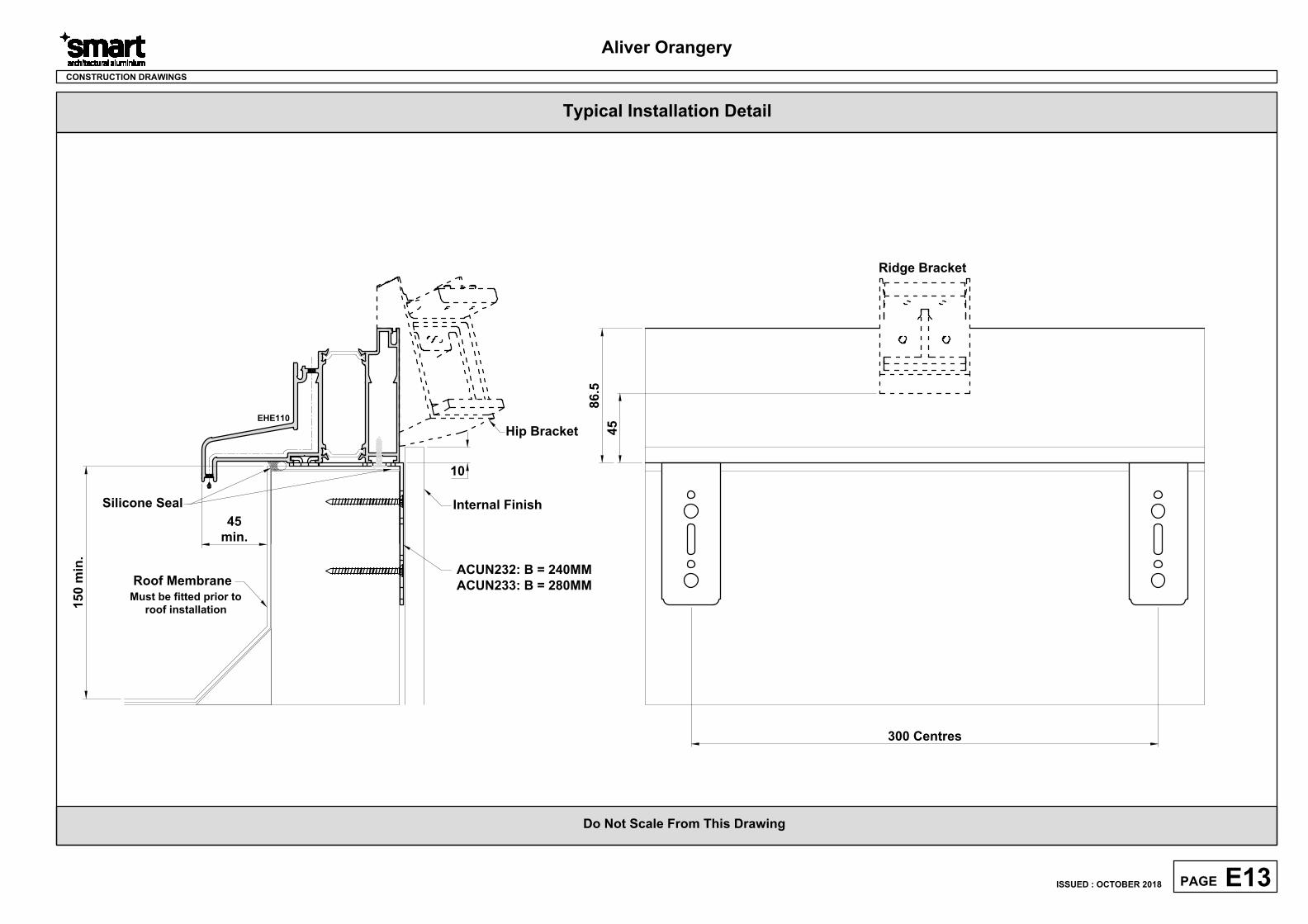
Aliver Orangery
E13PAGE
CONSTRUCTION DRAWINGS
EHE110
45
min.
15
0 m
in
.
10
Roof Membrane
Internal Finish
Silicone Seal
ACUN232: B = 240MM
ACUN233: B = 280MM
Hip Bracket
300 Centres
Ridge Bracket
45
86
.5
Typical Installation Detail
ISSUED : OCTOBER 2018
Must be fitted prior to
roof installation
Do Not Scale From This Drawing
Aliver Orangery
E14PAGE
CONSTRUCTION DRAWINGS
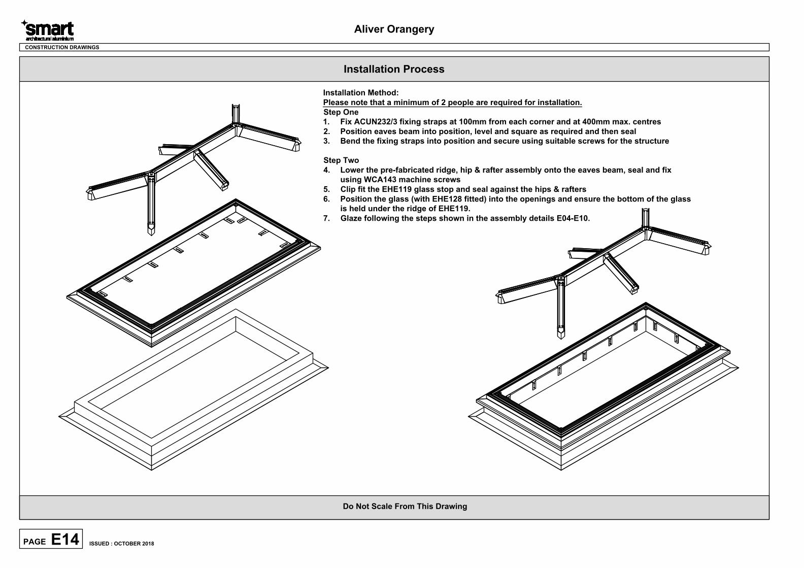
Installation Method:
Please note that a minimum of 2 people are required for installation.
Step One
1. Fix ACUN232/3 fixing straps at 100mm from each corner and at 400mm max. centres
2. Position eaves beam into position, level and square as required and then seal
3. Bend the fixing straps into position and secure using suitable screws for the structure
Step Two
4. Lower the pre-fabricated ridge, hip & rafter assembly onto the eaves beam, seal and fix
using WCA143 machine screws
5. Clip fit the EHE119 glass stop and seal against the hips & rafters
6. Position the glass (with EHE128 fitted) into the openings and ensure the bottom of the glass
is held under the ridge of EHE119.
7. Glaze following the steps shown in the assembly details E04-E10.
Installation Process
ISSUED : OCTOBER 2018
Do Not Scale From This Drawing
Aliver Orangery
CONSTRUCTION DRAWINGS
8
7
.
5
7
8
10
145.5
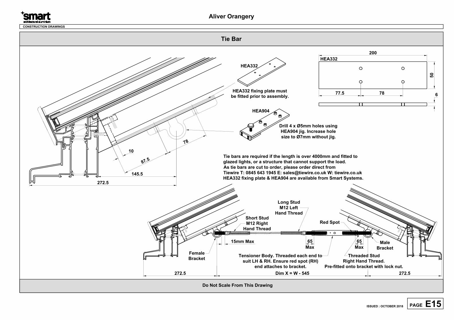
HEA904
Drill 4 x Ø5mm holes using
HEA904 jig. Increase hole
size to Ø7mm without jig.
HEA332
HEA332 fixing plate must
be fitted prior to assembly.
200
50
6
7877.5
HEA332
Short Stud
M12 Right
Hand Thread
15mm Max
Long Stud
M12 Left
Hand Thread
65
Max
65
Max
Tensioner Body. Threaded each end to
suit LH & RH. Ensure red spot (RH)
end attaches to bracket.
Red Spot
Threaded Stud
Right Hand Thread.
Pre-fitted onto bracket with lock nut.
Female
Bracket
Male
Bracket
Tie bars are required if the length is over 4000mm and fitted to
glazed lights, or a structure that cannot support the load.
As tie bars are cut to order, please order direct from
Tiewire T: 0845 643 1945 E: [email protected] W: tiewire.co.uk
HEA332 fixing plate & HEA904 are available from Smart Systems.
Dim X = W - 545
272.5
272.5 272.5
Tie Bar
E15PAGE
ISSUED : OCTOBER 2018
Do Not Scale From This Drawing
Aliver Orangery
CONSTRUCTION DRAWINGS
E16PAGE
ISSUED : OCTOBER 2018
Do Not Scale From This Drawing
Aliver Orangery
F01PAGE
CONSTRUCTION DRAWINGS
Sawing Tables
ISSUED : OCTOBER 2018
Do Not Scale From This Drawing
Aliver Orangery
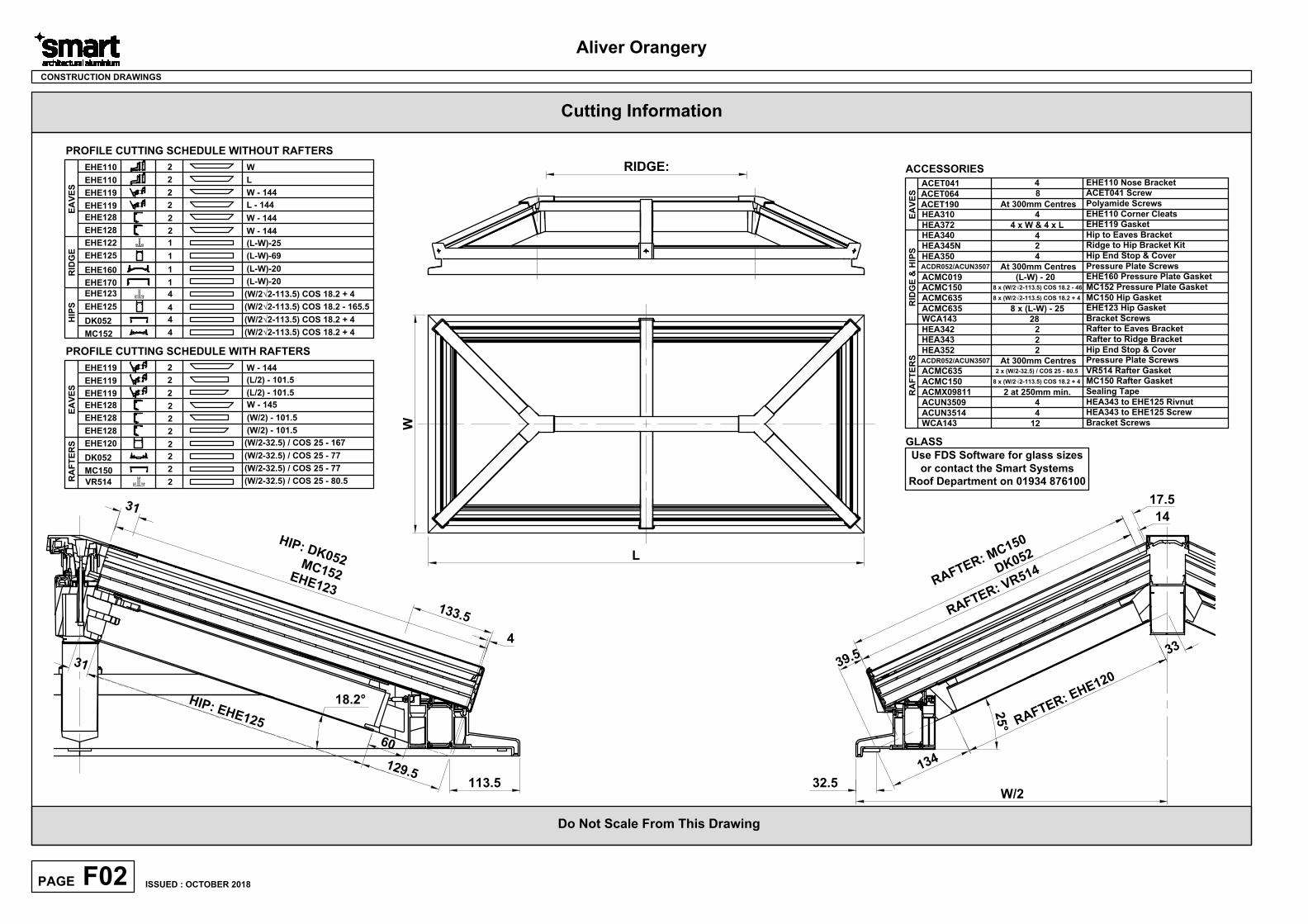
F02PAGE
CONSTRUCTION DRAWINGS
PROFILE CUTTING SCHEDULE WITHOUT RAFTERS
1
4
2EHE110 W
2 W - 144EHE119
EHE1102 L
4
DK052
MC152
4
1EHE170
1EHE160
2EHE119
L - 144
ACET041
HEA310
ACET064
4
8
4
EHE110 Nose Bracket
ACET041 Screw
EHE110 Corner Cleats
ACCESSORIES
EHE125
EHE125
EHE122 1
EHE1234
(L-W)-25
EA
VE
SR
ID
GE
HIP
S
L
W
(L-W)-69
(L-W)-20
(L-W)-20
(W/2√2-113.5) COS 18.2 + 4
(W/2√2-113.5) COS 18.2 + 4
(W/2√2-113.5) COS 18.2 - 165.5
(W/2√2-113.5) COS 18.2 + 4
113.5
1
2
9
.
5
H
I
P
:
E
H
E
1
2
5
18.2°
4
H
I
P
:
D
K
0
5
2
M
C
1
5
2
E
H
E
1
2
3
3
1
6
0
3
1
1
3
3
.
5
RIDGE:
PROFILE CUTTING SCHEDULE WITH RAFTERS
2 W - 144EHE119
2EHE119
(L/2) - 101.5
EA
VE
S
2EHE119
(L/2) - 101.5
RA
FT
ER
S
2
2
DK052
MC150
2
EHE120
VR514 2
(W/2-32.5) / COS 25 - 167
2
5
°
32.5
3
3
1
3
4
R
A
F
T
E
R
:
E
H
E
1
2
0
W/2
3
9
.
5
R
A
F
T
E
R
:
V
R
5
1
4
14
17.5
R
A
F
T
E
R
:
M
C
1
5
0
D
K
0
5
2
(W/2-32.5) / COS 25 - 77
(W/2-32.5) / COS 25 - 77
(W/2-32.5) / COS 25 - 80.5
2
EHE128
2
EHE128
2EHE128
W - 145
2
EHE128
2EHE128
W - 144
W - 144
EA
VE
SR
ID
GE
&
H
IP
S
HEA340 4
Hip to Eaves Bracket
HEA345N 2
Ridge to Hip Bracket Kit
HEA350 4
Hip End Stop & Cover
ACDR052/ACUN3507At 300mm Centres
Pressure Plate Screws
ACMC019 (L-W) - 20
EHE160 Pressure Plate Gasket
ACMC635MC150 Hip Gasket
ACMC635 8 x (L-W) - 25
RA
FT
ER
S
HEA342 2
Rafter to Eaves Bracket
HEA343 2
Rafter to Ridge Bracket
HEA352 2Hip End Stop & Cover
At 300mm Centres
Pressure Plate Screws
ACMC635VR514 Rafter Gasket
ACMC150
MC150 Rafter Gasket8 x (W/2√2-113.5) COS 18.2 + 4
HEA372 4 x W & 4 x L
EHE119 Gasket
2 x (W/2-32.5) / COS 25 - 80.5
8 x (W/2√2-113.5) COS 18.2 + 4
GLASS
Cutting Information
Use FDS Software for glass sizes
or contact the Smart Systems
Roof Department on 01934 876100
(W/2) - 101.5
(W/2) - 101.5
ISSUED : OCTOBER 2018
ACMC150MC152 Pressure Plate Gasket8 x (W/2√2-113.5) COS 18.2 - 46
ACDR052/ACUN3507
ACUN3509 4
ACUN3514 4
HEA343 to EHE125 Screw
WCA143 12
Bracket Screws
HEA343 to EHE125 Rivnut
WCA143 28
EHE123 Hip Gasket
Bracket Screws
ACMX09811 2 at 250mm min.
Sealing Tape
ACET190
Polyamide Screws
At 300mm Centres
Related Documents