Engineering Structures 30 (2008) 1938–1948 www.elsevier.com/locate/engstruct Connection overstrength in steel-braced RC frames Mahmoud R. Maheri a,* , H. Ghaffarzadeh b a Department of Civil Engineering, Shiraz University, P.O. Box 71345-1676, Shiraz, Iran b Department of Civil Engineering, University of Tabriz, Tabriz, Iran Received 11 March 2007; received in revised form 14 December 2007; accepted 20 December 2007 Available online 11 February 2008 Abstract Steel bracing systems can be used effectively for seismic retrofitting of existing RC buildings as well as for seismic design of new buildings. Although adaptation of bracing to upgrade the lateral load capacity of existing RC frames has been the subject of a number of successful studies, guidelines for its use in newly constructed RC frames need to be further developed. An important consideration in the design of steel-braced RC frames is the level of interaction between the strength capacities of the RC frame and the bracing system. In this paper, results of experimental and numerical investigations aimed at evaluating the level of capacity interaction between the two systems are discussed. For these investigations, cyclic loading tests are conducted on scaled moment resisting frames with and without bracing. It is found that the capacity interaction is primarily due to the connections overstrength. The experimental results are also used to calibrate full-scale numerical models. A parametric numerical investigation on the effects of the main problem variables is then conducted and the influence of each parameter on the level of the overstrength is determined. Based on these findings, guidelines for the seismic design of the internally cross-braced RC frames with direct connections are provided. c 2008 Published by Elsevier Ltd Keywords: Steel bracing; Reinforced concrete; Capacity interaction; Overstrength; Cyclic load testing 1. Introduction Traditionally, steel bracing system has been used to increase the lateral load resistance of steel structures. In recent years, the concept of steel bracing has also been applied to the retrofitting of reinforced concrete frames. Increased architectural flexibility, reduced weight of the structure, ease and speed of construction and the ability to choose more ductile systems can be considered as the main advantages of steel bracing in comparison with RC shear walls. Two bracing systems are generally used, external bracing and internal bracing. In external bracing, steel trusses or frames are attached either as a global external support to the building exterior or, more locally, to the face of the individual building frames. A number of investigators have reported on the efficiency of external bracing in seismic retrofitting of existing RC buildings [1–4]. Architectural concerns and difficulties in * Corresponding author. Tel.: +98 711 8321353; fax: +98 711 6286619. E-mail addresses: [email protected], [email protected] (M.R. Maheri). providing appropriate connections between the bracing system and RC frames are two of the shortcomings of this method. In internal bracing, steel bracing members are inserted in the empty space enclosed by columns and beams of RC frames. As a result, each unit frame is individually braced from within. The bracing may be attached to the RC frame either indirectly or directly. In the indirect internal bracing, a braced steel frame is positioned inside the RC frame. As a result, the transfer of load between the steel bracing and the concrete frame is carried out indirectly through the steel frame. Successful retrofits of existing buildings by indirect internal bracing using different forms of X , V and K concentric and eccentric braces have been reported in the literature [5–8]. In some repair and retrofitting cases, provision of the steel frame may be necessary to reduce the strength demand on an already damaged and weakened RC frame; however, in other instances the steel frame acts only as a costly connecting mechanism with inhibiting technical difficulties in fixing the steel frame to the RC frame. To overcome the shortcomings of the indirect internal bracing, Maheri and Sahebi [9] first recommended using direct connections between the brace elements and RC frame without 0141-0296/$ - see front matter c 2008 Published by Elsevier Ltd doi:10.1016/j.engstruct.2007.12.016

Welcome message from author
This document is posted to help you gain knowledge. Please leave a comment to let me know what you think about it! Share it to your friends and learn new things together.
Transcript
Engineering Structures 30 (2008) 1938–1948www.elsevier.com/locate/engstruct
Connection overstrength in steel-braced RC frames
Mahmoud R. Maheria,∗, H. Ghaffarzadehb
a Department of Civil Engineering, Shiraz University, P.O. Box 71345-1676, Shiraz, Iranb Department of Civil Engineering, University of Tabriz, Tabriz, Iran
Received 11 March 2007; received in revised form 14 December 2007; accepted 20 December 2007Available online 11 February 2008
Abstract
Steel bracing systems can be used effectively for seismic retrofitting of existing RC buildings as well as for seismic design of new buildings.Although adaptation of bracing to upgrade the lateral load capacity of existing RC frames has been the subject of a number of successful studies,guidelines for its use in newly constructed RC frames need to be further developed. An important consideration in the design of steel-braced RCframes is the level of interaction between the strength capacities of the RC frame and the bracing system. In this paper, results of experimentaland numerical investigations aimed at evaluating the level of capacity interaction between the two systems are discussed. For these investigations,cyclic loading tests are conducted on scaled moment resisting frames with and without bracing. It is found that the capacity interaction is primarilydue to the connections overstrength. The experimental results are also used to calibrate full-scale numerical models. A parametric numericalinvestigation on the effects of the main problem variables is then conducted and the influence of each parameter on the level of the overstrengthis determined. Based on these findings, guidelines for the seismic design of the internally cross-braced RC frames with direct connections areprovided.c© 2008 Published by Elsevier Ltd
Keywords: Steel bracing; Reinforced concrete; Capacity interaction; Overstrength; Cyclic load testing
1. Introduction
Traditionally, steel bracing system has been used to increasethe lateral load resistance of steel structures. In recentyears, the concept of steel bracing has also been appliedto the retrofitting of reinforced concrete frames. Increasedarchitectural flexibility, reduced weight of the structure, easeand speed of construction and the ability to choose more ductilesystems can be considered as the main advantages of steelbracing in comparison with RC shear walls.
Two bracing systems are generally used, external bracingand internal bracing. In external bracing, steel trusses orframes are attached either as a global external support to thebuilding exterior or, more locally, to the face of the individualbuilding frames. A number of investigators have reported on theefficiency of external bracing in seismic retrofitting of existingRC buildings [1–4]. Architectural concerns and difficulties in
∗ Corresponding author. Tel.: +98 711 8321353; fax: +98 711 6286619.E-mail addresses: [email protected], [email protected]
(M.R. Maheri).
0141-0296/$ - see front matter c© 2008 Published by Elsevier Ltddoi:10.1016/j.engstruct.2007.12.016
providing appropriate connections between the bracing systemand RC frames are two of the shortcomings of this method.
In internal bracing, steel bracing members are inserted in theempty space enclosed by columns and beams of RC frames. Asa result, each unit frame is individually braced from within. Thebracing may be attached to the RC frame either indirectly ordirectly. In the indirect internal bracing, a braced steel frameis positioned inside the RC frame. As a result, the transfer ofload between the steel bracing and the concrete frame is carriedout indirectly through the steel frame. Successful retrofits ofexisting buildings by indirect internal bracing using differentforms of X , V and K concentric and eccentric braces have beenreported in the literature [5–8]. In some repair and retrofittingcases, provision of the steel frame may be necessary to reducethe strength demand on an already damaged and weakened RCframe; however, in other instances the steel frame acts onlyas a costly connecting mechanism with inhibiting technicaldifficulties in fixing the steel frame to the RC frame.
To overcome the shortcomings of the indirect internalbracing, Maheri and Sahebi [9] first recommended using directconnections between the brace elements and RC frame without

M.R. Maheri, H. Ghaffarzadeh / Engineering Structures 30 (2008) 1938–1948 1939
the need for an intermediary steel frame. In an experimentalwork, they showed the ability of this bracing system to enhancethe strength capacity of RC frames.The later experimental workon directly-braced model frames by Tasnimi and Masoomi [10]also showed the applicability of this method. Recent analyticalwork carried out by Abou-Elfath and Ghobarah [11,12] on bothconcentric and eccentric direct internal bracing in non-ductileRC buildings also showed an improvement in the seismicperformance, particularly when using eccentric bracing.
In a continuation of their previous work, Maheri et al. [13]conducted experimental investigations on pushover responseof scaled RC frames; braced with both diagonal bracing andknee bracing systems. In this study the effectiveness of thetwo bracing systems in increasing some seismic performanceparameters was shown. Also, in a theoretical study, Maheri andAkbari presented the behaviour factor, R, for this class of dualsystems [14].
Appropriate design of direct connections between thebracing members and the RC frame is important to achievethe required lateral load capacity. Maheri and Hadjipour [15]proposed a connection that minimizes the eccentricity ofthe brace member force. This allows transferring the braceforce to the corner of the RC frame without producinglocal damage in concrete members. Using the results ofan experimental program conducted on a number of full-scale connections, they also presented design guidelines forthe brace–frame connections in the new construction. Recentexperimental works by Youssef et al. [16] and Ghaffarzadehand Maheri [17,18] have shown further that different directly-connected internal bracing systems can be used effectively inthe retrofitting of existing concrete frames as well as shearresisting elements for the construction of new RC structures.
An important consideration in the design of internally-braced RC frames with direct brace–frame connections isthe level of interaction between the strength capacitiesof the RC frame and the bracing system. In this paper,results of experimental and numerical investigations aimedat investigating the causes and evaluating the level of thisinteraction are discussed. Three specimens representing RCmoment frames with moderate ductility, two of which werebraced, were designed. Current seismic codes were used todesign the moment frames. The model frames were subjectedto cyclic loads. Their test results are compared and discussed.These results are also used as the basis for developing andcalibrating numerical models of full-scale frames. Using thenumerical models, a parametric investigation is carried out todetermine the role of the main variable parameters affectingthe level of capacity interaction between the RC frame and thebracing system.
2. Experimental program
2.1. Test specimens and results
Unit frames were modelled using a mid-span panelmeasuring 4.0 m by 3.0 m from the third floor of a four-storey frame with the dimensions of 12.0 m by 12.0 m. It
was assumed that the building is located in a highly seismicarea. Two lateral load resisting systems, namely; momentframes and braced moment frames, were considered. Thegravity and earthquake forces acting on the moment framewere determined in accordance with Iranian Seismic Code [19]using the seismic force reduction factor for moment frames withmoderate ductility. Appropriate upgrading or added seismicloads were considered for the bracing system in the bracedmoment frames, based on the scaled capacities of the steelsections used in the model frames as discussed below.
The size of the model frames was limited to the availablelaboratory space and equipment limits. A 2/5 scaled model,measuring 1.76 m by 1.36 m, was found satisfactory. Thegravity forces acting on the models were also scaled down by afactor of (2/5)2. This factor was chosen to keep the stresses inthe scaled model similar to the full-scale panel. The boundaryconditions for the tested frames were chosen such that theinternal forces developed in them are similar to those developedin reality. Two hinged supports were thus used to support theframes. The dimensions of the beams and columns were chosento be 140 mm by 160 mm.
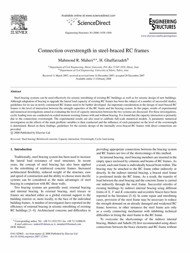
Three frames were designed and constructed, one momentframe (F1) and two moment frames with bracing (FX1 andFX2). The RC moment frames in the three frames hadidentical dimensions and flexural reinforcements, giving themidentical flexural capacities. The moment frames were designedaccording to ACI 318-02 [20] and their detailing was donein accordance with the ACI special provisions for seismicdesign. Reinforcement details for the RC frames are shownin Fig. 1. AISC-LRFD [21] was used to design the bracemembers and their welded connections to the guest plates. Theirdesign was also checked using the AISC seismic provisionsfor steel structures [22]. Two types of bracing members wereconsidered; slender double angle cross-section for the frameFX1 and non-slender channel cross-section for frame FX2.Details of these sections are also shown in Fig. 1. The RCframes were first constructed. Two 150 × 120 × 10 mm plateswere placed at each corner of the frames. The plates were castin concrete using four 16 mm stud rods. The bracing memberswere then attached to the RC frame at the four corners using150 × 150 × 10 mm gusset plates.
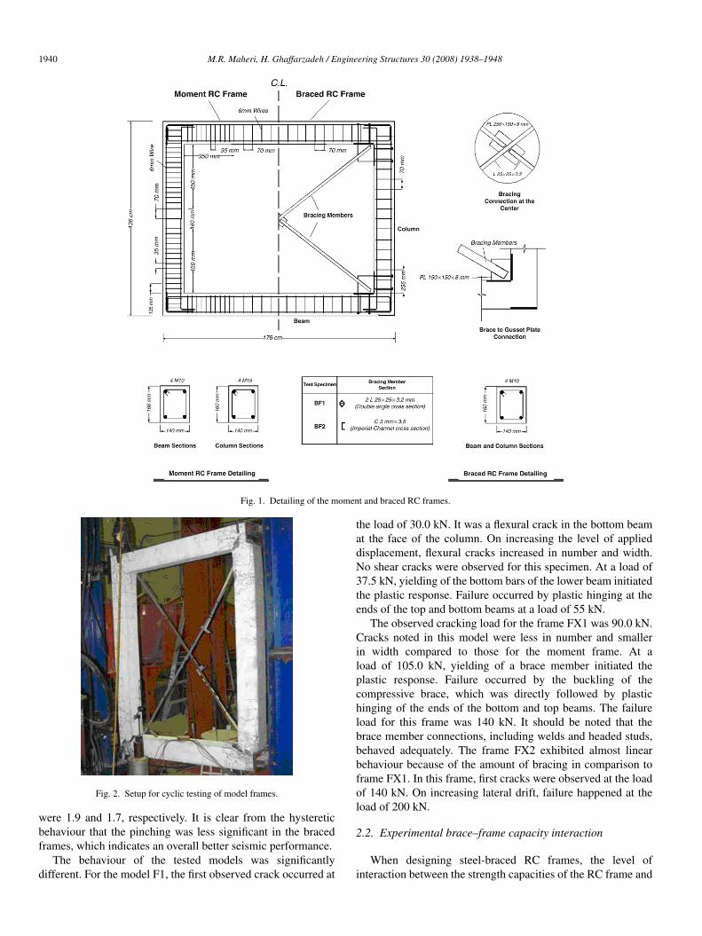
The frames were tested using the setup presented in [18](Fig. 2). An actuator was used to apply several cycles of in-plane shear load using a displacement-controlled approach. Ineach cycle, the actuator was first pulled to a displacement of5 mm (drift of 0.417%) then pushed to the same displacement.The displacement was increased in the following cycles byincrements of 5 mm. Strain gauges were used to monitor strainsin the beam–column joint, the transverse reinforcement of thecolumns, and the longitudinal reinforcement of the beams.
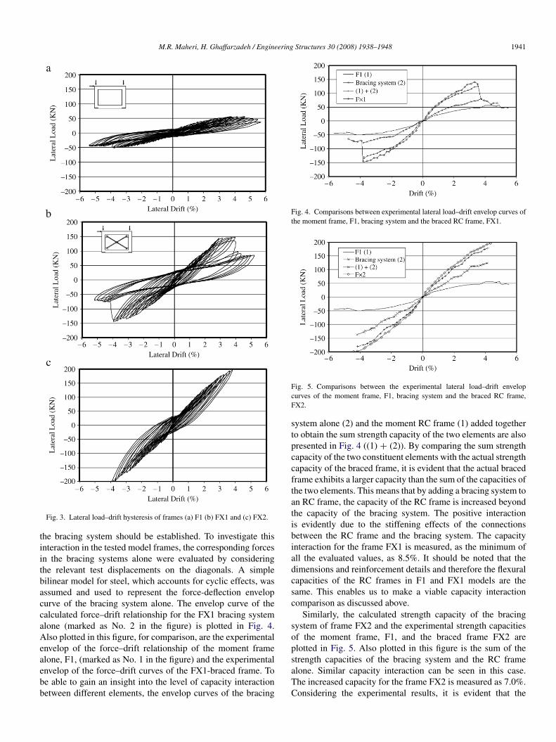
The lateral load–drift hysteresis for the frames F1, FX1 andFX2 are shown in Fig. 3. The initial stiffness of the bracedframe was expectedly higher than that of the unbraced frame.The yield and failure drifts of the frame F1 were 1.67% and5.00%, respectively and those of the frames FX1 and FX2 were2.08%, 4.0%, and 2.5%, 4.3%, respectively. This shows that theductility of frame F1 was 3.0 and that of frames FX1 and FX2
1940 M.R. Maheri, H. Ghaffarzadeh / Engineering Structures 30 (2008) 1938–1948
Fig. 1. Detailing of the moment and braced RC frames.
Fig. 2. Setup for cyclic testing of model frames.
were 1.9 and 1.7, respectively. It is clear from the hystereticbehaviour that the pinching was less significant in the bracedframes, which indicates an overall better seismic performance.
The behaviour of the tested models was significantlydifferent. For the model F1, the first observed crack occurred at
the load of 30.0 kN. It was a flexural crack in the bottom beamat the face of the column. On increasing the level of applieddisplacement, flexural cracks increased in number and width.No shear cracks were observed for this specimen. At a load of37.5 kN, yielding of the bottom bars of the lower beam initiatedthe plastic response. Failure occurred by plastic hinging at theends of the top and bottom beams at a load of 55 kN.
The observed cracking load for the frame FX1 was 90.0 kN.Cracks noted in this model were less in number and smallerin width compared to those for the moment frame. At aload of 105.0 kN, yielding of a brace member initiated theplastic response. Failure occurred by the buckling of thecompressive brace, which was directly followed by plastichinging of the ends of the bottom and top beams. The failureload for this frame was 140 kN. It should be noted that thebrace member connections, including welds and headed studs,behaved adequately. The frame FX2 exhibited almost linearbehaviour because of the amount of bracing in comparison toframe FX1. In this frame, first cracks were observed at the loadof 140 kN. On increasing lateral drift, failure happened at theload of 200 kN.
2.2. Experimental brace–frame capacity interaction
When designing steel-braced RC frames, the level ofinteraction between the strength capacities of the RC frame and
M.R. Maheri, H. Ghaffarzadeh / Engineering Structures 30 (2008) 1938–1948 1941
Fig. 3. Lateral load–drift hysteresis of frames (a) F1 (b) FX1 and (c) FX2.
the bracing system should be established. To investigate thisinteraction in the tested model frames, the corresponding forcesin the bracing systems alone were evaluated by consideringthe relevant test displacements on the diagonals. A simplebilinear model for steel, which accounts for cyclic effects, wasassumed and used to represent the force-deflection envelopcurve of the bracing system alone. The envelop curve of thecalculated force–drift relationship for the FX1 bracing systemalone (marked as No. 2 in the figure) is plotted in Fig. 4.Also plotted in this figure, for comparison, are the experimentalenvelop of the force–drift relationship of the moment framealone, F1, (marked as No. 1 in the figure) and the experimentalenvelop of the force–drift curves of the FX1-braced frame. Tobe able to gain an insight into the level of capacity interactionbetween different elements, the envelop curves of the bracing
Fig. 4. Comparisons between experimental lateral load–drift envelop curves ofthe moment frame, F1, bracing system and the braced RC frame, FX1.
Fig. 5. Comparisons between the experimental lateral load–drift envelopcurves of the moment frame, F1, bracing system and the braced RC frame,FX2.
system alone (2) and the moment RC frame (1) added togetherto obtain the sum strength capacity of the two elements are alsopresented in Fig. 4 ((1) + (2)). By comparing the sum strengthcapacity of the two constituent elements with the actual strengthcapacity of the braced frame, it is evident that the actual bracedframe exhibits a larger capacity than the sum of the capacities ofthe two elements. This means that by adding a bracing system toan RC frame, the capacity of the RC frame is increased beyondthe capacity of the bracing system. The positive interactionis evidently due to the stiffening effects of the connectionsbetween the RC frame and the bracing system. The capacityinteraction for the frame FX1 is measured, as the minimum ofall the evaluated values, as 8.5%. It should be noted that thedimensions and reinforcement details and therefore the flexuralcapacities of the RC frames in F1 and FX1 models are thesame. This enables us to make a viable capacity interactioncomparison as discussed above.
Similarly, the calculated strength capacity of the bracingsystem of frame FX2 and the experimental strength capacitiesof the moment frame, F1, and the braced frame FX2 areplotted in Fig. 5. Also plotted in this figure is the sum of thestrength capacities of the bracing system and the RC framealone. Similar capacity interaction can be seen in this case.The increased capacity for the frame FX2 is measured as 7.0%.Considering the experimental results, it is evident that the
1942 M.R. Maheri, H. Ghaffarzadeh / Engineering Structures 30 (2008) 1938–1948
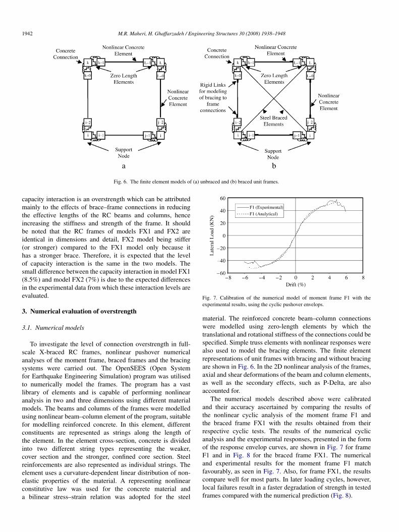
Fig. 6. The finite element models of (a) unbraced and (b) braced unit frames.
capacity interaction is an overstrength which can be attributedmainly to the effects of brace–frame connections in reducingthe effective lengths of the RC beams and columns, henceincreasing the stiffness and strength of the frame. It shouldbe noted that the RC frames of models FX1 and FX2 areidentical in dimensions and detail, FX2 model being stiffer(or stronger) compared to the FX1 model only because ithas a stronger brace. Therefore, it is expected that the levelof capacity interaction is the same in the two models. Thesmall difference between the capacity interaction in model FX1(8.5%) and model FX2 (7%) is due to the expected differencesin the experimental data from which these interaction levels areevaluated.
3. Numerical evaluation of overstrength
3.1. Numerical models
To investigate the level of connection overstrength in full-scale X-braced RC frames, nonlinear pushover numericalanalyses of the moment frame, braced frames and the bracingsystems were carried out. The OpenSEES (Open Systemfor Earthquake Engineering Simulation) program was utilisedto numerically model the frames. The program has a vastlibrary of elements and is capable of performing nonlinearanalysis in two and three dimensions using different materialmodels. The beams and columns of the frames were modelledusing nonlinear beam–column element of the program, suitablefor modelling reinforced concrete. In this element, differentconstituents are represented as strings along the length ofthe element. In the element cross-section, concrete is dividedinto two different string types representing the weaker,cover section and the stronger, confined core section. Steelreinforcements are also represented as individual strings. Theelement uses a curvature-dependent linear distribution of non-elastic properties of the material. A representing nonlinearconstitutive law was used for the concrete material anda bilinear stress–strain relation was adopted for the steel
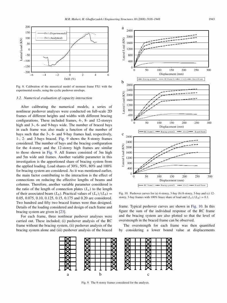
Fig. 7. Calibration of the numerical model of moment frame F1 with theexperimental results, using the cyclic pushover envelops.
material. The reinforced concrete beam–column connectionswere modelled using zero-length elements by which thetranslational and rotational stiffness of the connections could bespecified. Simple truss elements with nonlinear responses werealso used to model the bracing elements. The finite elementrepresentations of unit frames with bracing and without bracingare shown in Fig. 6. In the 2D nonlinear analysis of the frames,axial and shear deformations of the beam and column elements,as well as the secondary effects, such as P-Delta, are alsoaccounted for.
The numerical models described above were calibratedand their accuracy ascertained by comparing the results ofthe nonlinear cyclic analysis of the moment frame F1 andthe braced frame FX1 with the results obtained from theirrespective cyclic tests. The results of the numerical cyclicanalysis and the experimental responses, presented in the formof the response envelop curves, are shown in Fig. 7 for frameF1 and in Fig. 8 for the braced frame FX1. The numericaland experimental results for the moment frame F1 matchfavourably, as seen in Fig. 7. Also, for frame FX1, the resultscompare well for most parts. In later loading cycles, however,local failures result in a faster degradation of strength in testedframes compared with the numerical prediction (Fig. 8).
M.R. Maheri, H. Ghaffarzadeh / Engineering Structures 30 (2008) 1938–1948 1943
Fig. 8. Calibration of the numerical model of moment frame FX1 with theexperimental results, using the cyclic pushover envelops.
3.2. Numerical evaluation of capacity interaction
After calibrating the numerical models, a series ofnonlinear pushover analyses were conducted on full-scale 2Dframes of different heights and widths with different bracingconfigurations. These included frames, 4-, 8- and 12-storeyshigh and 3-, 6- and 9-bays wide. The number of braced baysin each frame was also made a function of the number ofbays such that the 3-, 6- and 9-bay frames had, respectively,1-, 2- and 3-bays braced. Fig. 9 shows the 8-storey framesconsidered. The number of bays and the bracing configurationfor the 4-storey and the 12-storey high frames are similarto those shown in Fig. 9. All frames consisted of 3m highand 5m wide unit frames. Another variable parameter in thisinvestigation is the apportioned share of bracing system fromthe applied loading. Load shares of 30%, 50%, 80% and 100%for bracing system are considered. As it was mentioned earlier,the main factor contributing to the interaction is the effect ofconnections on reducing the effective lengths of beams andcolumns. Therefore, another variable parameter considered isthe ratio of the length of connection plates (Le) to the lengthof their associated beam (Lb). Practical values of (Le)/(Lb) =
0.05, 0.075, 0.10, 0.125, 0.15, 0.175 and 0.20 are considered.Two hundred and fifty two braced frames were thus designed.Details of the loading considered and design of each frame andbracing system are given in [23].
For each frame, three nonlinear pushover analyses werecarried out. These included; (i) pushover analysis of the RCframe without the bracing system, (ii) pushover analysis of thebracing system alone and (iii) pushover analysis of the braced
Fig. 9. The 8-storey frames considered for the analysis.
Fig. 10. Pushover curves for (a) 4-storey, 3-bay (b) 8-storey, 3-bay and (c) 12-storey, 3-bay frames with 100% brace share of load and (Le)/(Lb) = 0.1.
frame. Typical pushover curves are shown in Fig. 10. In thisfigure the sum of the individual response of the RC frameand the bracing system are also plotted so that the level ofoverstrength in the braced frame can be observed.
The overstrength for each frame was then quantifiedby considering a lower bound value at displacements
1944 M.R. Maheri, H. Ghaffarzadeh / Engineering Structures 30 (2008) 1938–1948
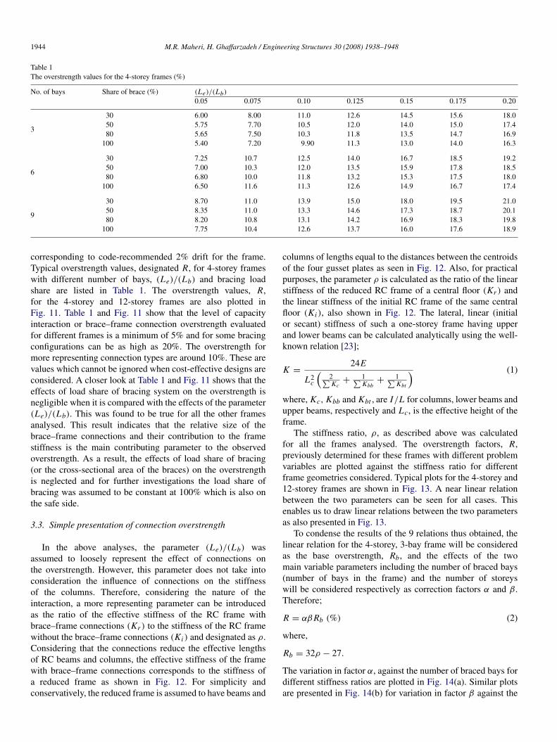
Table 1The overstrength values for the 4-storey frames (%)
No. of bays Share of brace (%) (Le)/(Lb)
0.05 0.075 0.10 0.125 0.15 0.175 0.20
3
30 6.00 8.00 11.0 12.6 14.5 15.6 18.050 5.75 7.70 10.5 12.0 14.0 15.0 17.480 5.65 7.50 10.3 11.8 13.5 14.7 16.9
100 5.40 7.20 9.90 11.3 13.0 14.0 16.3
6
30 7.25 10.7 12.5 14.0 16.7 18.5 19.250 7.00 10.3 12.0 13.5 15.9 17.8 18.580 6.80 10.0 11.8 13.2 15.3 17.5 18.0
100 6.50 11.6 11.3 12.6 14.9 16.7 17.4
9
30 8.70 11.0 13.9 15.0 18.0 19.5 21.050 8.35 11.0 13.3 14.6 17.3 18.7 20.180 8.20 10.8 13.1 14.2 16.9 18.3 19.8
100 7.75 10.4 12.6 13.7 16.0 17.6 18.9
corresponding to code-recommended 2% drift for the frame.Typical overstrength values, designated R, for 4-storey frameswith different number of bays, (Le)/(Lb) and bracing loadshare are listed in Table 1. The overstrength values, R,for the 4-storey and 12-storey frames are also plotted inFig. 11. Table 1 and Fig. 11 show that the level of capacityinteraction or brace–frame connection overstrength evaluatedfor different frames is a minimum of 5% and for some bracingconfigurations can be as high as 20%. The overstrength formore representing connection types are around 10%. These arevalues which cannot be ignored when cost-effective designs areconsidered. A closer look at Table 1 and Fig. 11 shows that theeffects of load share of bracing system on the overstrength isnegligible when it is compared with the effects of the parameter(Le)/(Lb). This was found to be true for all the other framesanalysed. This result indicates that the relative size of thebrace–frame connections and their contribution to the framestiffness is the main contributing parameter to the observedoverstrength. As a result, the effects of load share of bracing(or the cross-sectional area of the braces) on the overstrengthis neglected and for further investigations the load share ofbracing was assumed to be constant at 100% which is also onthe safe side.
3.3. Simple presentation of connection overstrength
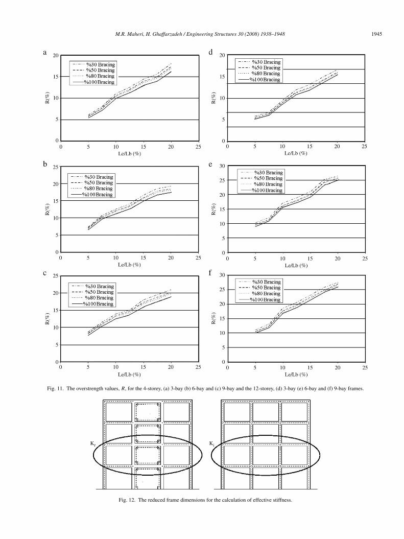
In the above analyses, the parameter (Le)/(Lb) wasassumed to loosely represent the effect of connections onthe overstrength. However, this parameter does not take intoconsideration the influence of connections on the stiffnessof the columns. Therefore, considering the nature of theinteraction, a more representing parameter can be introducedas the ratio of the effective stiffness of the RC frame withbrace–frame connections (Kr ) to the stiffness of the RC framewithout the brace–frame connections (Ki ) and designated as ρ.Considering that the connections reduce the effective lengthsof RC beams and columns, the effective stiffness of the framewith brace–frame connections corresponds to the stiffness ofa reduced frame as shown in Fig. 12. For simplicity andconservatively, the reduced frame is assumed to have beams and
columns of lengths equal to the distances between the centroidsof the four gusset plates as seen in Fig. 12. Also, for practicalpurposes, the parameter ρ is calculated as the ratio of the linearstiffness of the reduced RC frame of a central floor (Kr ) andthe linear stiffness of the initial RC frame of the same centralfloor (Ki ), also shown in Fig. 12. The lateral, linear (initialor secant) stiffness of such a one-storey frame having upperand lower beams can be calculated analytically using the well-known relation [23];
K =24E
L2c
(2∑Kc
+1∑Kbb
+1∑Kbt
) (1)
where, Kc, Kbb and Kbt , are I/L for columns, lower beams andupper beams, respectively and Lc, is the effective height of theframe.
The stiffness ratio, ρ, as described above was calculatedfor all the frames analysed. The overstrength factors, R,previously determined for these frames with different problemvariables are plotted against the stiffness ratio for differentframe geometries considered. Typical plots for the 4-storey and12-storey frames are shown in Fig. 13. A near linear relationbetween the two parameters can be seen for all cases. Thisenables us to draw linear relations between the two parametersas also presented in Fig. 13.
To condense the results of the 9 relations thus obtained, thelinear relation for the 4-storey, 3-bay frame will be consideredas the base overstrength, Rb, and the effects of the twomain variable parameters including the number of braced bays(number of bays in the frame) and the number of storeyswill be considered respectively as correction factors α and β.Therefore;
R = αβ Rb (%) (2)
where,
Rb = 32ρ − 27.
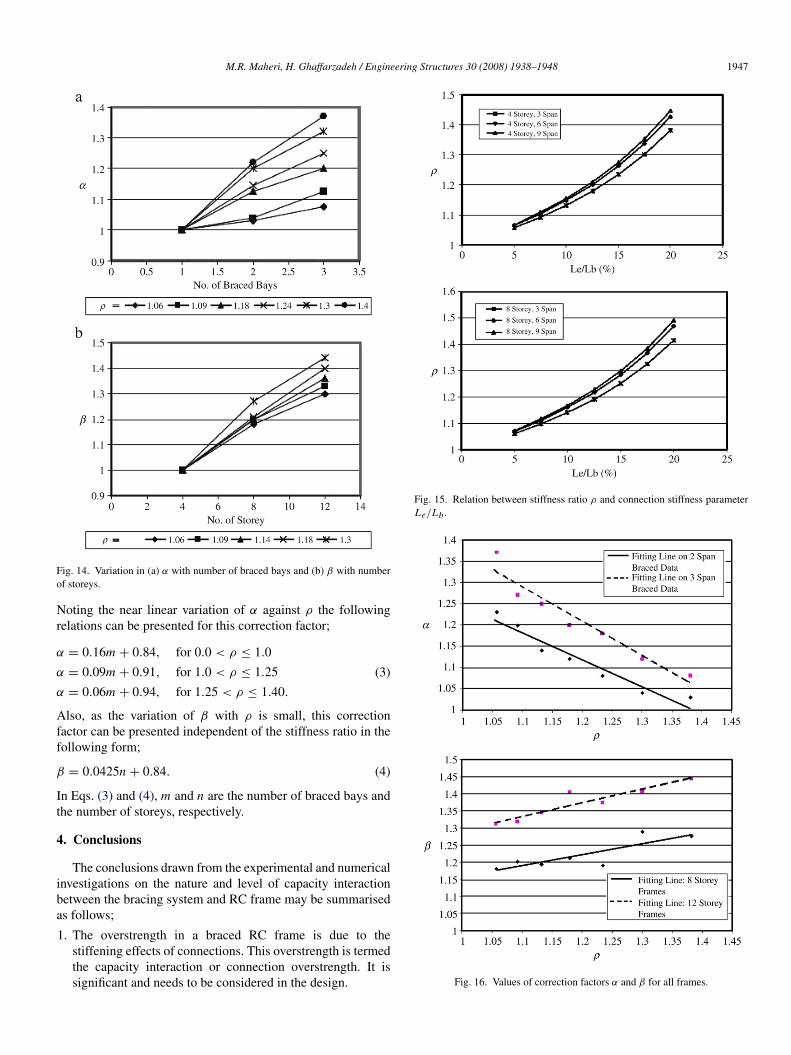
The variation in factor α, against the number of braced bays fordifferent stiffness ratios are plotted in Fig. 14(a). Similar plotsare presented in Fig. 14(b) for variation in factor β against the
M.R. Maheri, H. Ghaffarzadeh / Engineering Structures 30 (2008) 1938–1948 1945
Fig. 11. The overstrength values, R, for the 4-storey, (a) 3-bay (b) 6-bay and (c) 9-bay and the 12-storey, (d) 3-bay (e) 6-bay and (f) 9-bay frames.
Fig. 12. The reduced frame dimensions for the calculation of effective stiffness.

1946 M.R. Maheri, H. Ghaffarzadeh / Engineering Structures 30 (2008) 1938–1948
Fig. 13. The overstrength, R as a function of ρ for (a) 4-storey, 3-bay, (b) 4-storey, 6-bay (c) 4-storey, 9-bay (d) 12-storey, 3-bay, (e) 12-storey, 6-bay and (d)12-storey, 9-bay frames.
number of storeys. Fig. 14(a) indicates that the dependence offactor α on the number of braced panels is strongly influencedby the stiffness ratio, ρ; such that for weaker brace–frameconnections, the number of braced panels has marginal effecton α, whereas for stiffer brace–frame connections, α variesconsiderably with the number of braced panels. It is evidentthat the contribution of the number of bays by themselves tothe stiffness of the frame is minimal. Any contribution to thestiffness arises from the number of braced bays and the stiffnessof connections. This point can also be deduced from Fig. 15,in which the frame stiffness ratio, ρ, is plotted against the
connection stiffness parameter (Le)/(Lb) for the 4-storey and8-storey frames.
Variations in factor β, presented graphically in Fig. 14(b),however, show that the effect of brace–frame connectionstiffness on this parameter is markedly less than the effect ofnumber of storeys. This is expected when we consider the factthat, unlike the number of bays, the height of a frame greatlyinfluences its stiffness.
In order that quantitative relations can be drawn between thefactors α and β and the stiffness ratio ρ, the former parametersare plotted against the latter in Fig. 16(a) and (b), respectively.
M.R. Maheri, H. Ghaffarzadeh / Engineering Structures 30 (2008) 1938–1948 1947
Fig. 14. Variation in (a) α with number of braced bays and (b) β with numberof storeys.
Noting the near linear variation of α against ρ the followingrelations can be presented for this correction factor;
α = 0.16m + 0.84, for 0.0 < ρ ≤ 1.0
α = 0.09m + 0.91, for 1.0 < ρ ≤ 1.25
α = 0.06m + 0.94, for 1.25 < ρ ≤ 1.40.
(3)
Also, as the variation of β with ρ is small, this correctionfactor can be presented independent of the stiffness ratio in thefollowing form;
β = 0.0425n + 0.84. (4)
In Eqs. (3) and (4), m and n are the number of braced bays andthe number of storeys, respectively.
4. Conclusions
The conclusions drawn from the experimental and numericalinvestigations on the nature and level of capacity interactionbetween the bracing system and RC frame may be summarisedas follows;
1. The overstrength in a braced RC frame is due to thestiffening effects of connections. This overstrength is termedthe capacity interaction or connection overstrength. It issignificant and needs to be considered in the design.
Fig. 15. Relation between stiffness ratio ρ and connection stiffness parameterLe/Lb .
Fig. 16. Values of correction factors α and β for all frames.
1948 M.R. Maheri, H. Ghaffarzadeh / Engineering Structures 30 (2008) 1938–1948
2. The important parameters affecting the capacity interactionare recognised as the number of braced bays and the numberof frame storeys. The third important parameter is thestiffening effects of the connections taken into considerationas a stiffness ratio.
3. The connection overstrength, R, for different 2D concentri-cally cross-braced frames are determined and presented insimple forms for use in the design of internally-braced RCframes.
4. Presentation of the connection overstrength in the form ofa frame stiffness ratio, ρ, may enable us to use the resultsand formulations presented here for other types of concentricand eccentric bracing systems. This point, however, needsfurther verification.
References
[1] Bush TD, Jones EA, Jirsa JO. Behavior of RC frame strengthened usingstructural-steel bracing. Journal of Structural Engineering, ASCE 1991;117(4):1115–26.
[2] Badoux M, Jirsa JO. Steel bracing of RC frames for seismic retrofitting.Journal of Structural Engineering, ASCE 1990;116(1):55–74.
[3] Higashi Y, Endo T, Shimizu Y. Experimental studies on retrofitting ofreinforced concrete structural members. In: Proceedings of the secondseminar on repair and retrofit of structures. Ann Arbor (MI): NationalScience Foundation; 1981. p. 126–55.
[4] Nateghi-Alahi F. Seismic strengthening of eight-storey RC apartmentbuilding using steel braces. Engineering Structures 1995;17(6):455–61.
[5] Usami H, Azuchi T, Kamiya Y, Ban H. Seismic strengthening of existingreinforced concrete buildings in Shizuoka prefecture, Japan. In: Proc. 9thworld conf. on earthquake engineering, vol. VII. 1988. p. 421–6.
[6] Ohishi H, Takahashi M, Yamazaki Y. A seismic strengthening design andpractice of an existing reinforced concrete school building in Shizuokacity. In: Proc. 9th world conf. on earthquake engineering, vol. VII. 1988,p. 415–20.
[7] Hjelmstad KD, Foutch DA, Del Valle E, Downs RE. Forced vibrationstudies of an RC building retrofit with steel bracing. In: Proc. 9th worldconf. on earthquake engineering, vol. VII. 1988. p. 469–74.
[8] Tagawa Y, Aoki H, Huang T, Masuda H. Experimental study of newseismic strengthening method for existing RC structure. In: 10th worldconf. on earthquake engineering. 1992, p. 5193–8.
[9] Maheri MR, Sahebi A. Use of steel bracing in reinforced concrete frames.Engineering Structures 1997;19(12):1018–24.
[10] Tasnimi A, Masoomi A. Evaluation of response reinforced concreteframes strengthened with steel bracing. In: Proc. 3rd int. conf. on seism.and earthq. engng. 1999 [in Persian].
[11] Abou-Elfath H, Ghobarah A. Behaviour of reinforced concrete framesrehabilitated with concentric steel bracing. Canadian Journal of CivilEngineering 2000;27:433–44.
[12] Ghobarah A, Abou-Elfath H. Rehabilitation of a reinforced concreteframes using eccentric steel bracing. Engineering Structures 2001;23:745–55.
[13] Maheri MR, Kousari R, Razazan M. Pushover tests on steel X-braced andknee-braced RC frames. Engineering Structures 2003;25:1697–705.
[14] Maheri MR, Akbari R. Seismic behaviour factor, R, for steel X-bracedand knee-braced RC buildings. Engineering Structures 2003;25(12):1505–1513.
[15] Maheri MR, Hadjipour A. Experimental investigation and design ofsteel brace connection to RC frame. Engineering Structures 2003;25:1707–1714.
[16] Youssef MA, Ghaffarzadeh H, Nehdi M. Seismic performance of RCframes with concentric internal steel bracing. Engineering Structures2007;29(7):1561–8.
[17] Ghaffarzadeh H, Maheri MR. Mechanical compression release device insteel bracing system for retrofitting RC frames. Earthquake Engineeringand Engineering Vibration 2006;5(1).
[18] Ghaffarzadeh H, Maheri MR. Cyclic tests on the internally braced RCframes. Journal of Seismology and Earthquake Engineering 2006;8(3).
[19] Iranian code of practice for seismic resistance design of buildings.Standard No. 2800, 3rd ed. 2005.
[20] ACI Committee 318. Building code requirements for reinforced concrete(ACI 318-02). Detroit (MI): American Concrete Institute; 2002.
[21] AISC Manual of steel construction: load and resistance factor design. 3rded. Chicago (IL): American Institute of Steel Construction; 2001.
[22] AISC. Seismic provisions for structural steel buildings. Chicago (IL):American Institute of Steel Construction; 2002.
[23] Ghaffarzadeh H. Design basis for internally-braced RC frames. Ph.D.thesis, Shiraz (Iran): Shiraz University; 2006.
Related Documents


