MAHALAKSHMI ENGINEERING COLLEGE TIRUCHIRAPALLI- 621213. QUESTION BANK DEPARTMENT: EEE SEMESTER – V SUBJECT NAME: Transmission and Distribution Unit 3 1. What is meant by Ferranti Effect?(AUC Nov/Dec’11) (AUC Nov/Dec’10) This is the effect that exists in long transmission lines due to the presence of large capacitance. It is the phenomenon by which the magnitude of the voltage at the receiving and becomes higher than the voltage at the sending end when a long line is open circuited or lightly loaded. 2. Distinguish between phase and attenuation constant. (AUC Nov/Dec’11) S.No Phase Constant Attenuation constant 1. The imaginary part of propagation constant is β. The real part of propagation constant is α. 2. It determines the change in phase of wave per unit length of the line. It determines the change in magnitude per unit length of the line of the wave. 3. It is expressed in radians per unit length. It is expressed in nepers per unit length. 3. Define efficiency and regulation of transmission line. (AUC April/May’10) Voltage Regulation: Voltage regulation of the line is defined as the change in receiving end voltage from no load to full load expressed as a percentage of full load keeping the sending end voltage and frequency constant. % regulation = 100 x Vr Vr Vs Transmission efficiency: The ration of receiving end power to sending end power of a transmission line is known as transmission efficiency of the line. 4. How are transmission lines classified? (AUC April/May’10) Transmission lines are classified as i. SHORT LINES- Length less than 80km(<20KV) ii. MEDIUM LINES- Length 80km to 160km(20KV < 100KV) iii. LONG LINES- Length above 160km(More than 100KV) 5. State Ferranti Effect. Draw the relevant pharos diagram. (AUC Nov/Dec’09) In a medium or long transmission line, when open circuited or load lightly, the receiving end voltage is found to be more than the sending end voltage. This phenomenon of rise in voltage at the receiving end of the open circuited or lightly loaded line is called Ferranti effect.

Welcome message from author
This document is posted to help you gain knowledge. Please leave a comment to let me know what you think about it! Share it to your friends and learn new things together.
Transcript
MAHALAKSHMI
ENGINEERING COLLEGE
TIRUCHIRAPALLI- 621213.
QUESTION BANK
DEPARTMENT: EEE SEMESTER – V
SUBJECT NAME: Transmission and Distribution
Unit 3
1. What is meant by Ferranti Effect?(AUC Nov/Dec’11) (AUC Nov/Dec’10)
This is the effect that exists in long transmission lines due to the presence of
large capacitance. It is the phenomenon by which the magnitude of the voltage at
the receiving and becomes higher than the voltage at the sending end when a long
line is open circuited or lightly loaded.
2. Distinguish between phase and attenuation constant. (AUC Nov/Dec’11)
S.No Phase Constant Attenuation constant
1. The imaginary part of propagation constant is β.
The real part of propagation constant is α.
2. It determines the change in phase of wave per unit length of the line.
It determines the change in magnitude per unit length of the line of the wave.
3. It is expressed in radians per unit length.
It is expressed in nepers per unit length.
3. Define efficiency and regulation of transmission line. (AUC April/May’10)
Voltage Regulation: Voltage regulation of the line is defined as the change
in receiving end voltage from no load to full load expressed as a percentage of full
load keeping the sending end voltage and frequency constant.
% regulation = 100xVr
VrVs
Transmission efficiency: The ration of receiving end power to sending end
power of a transmission line is known as transmission efficiency of the line.
4. How are transmission lines classified? (AUC April/May’10)
Transmission lines are classified as
i. SHORT LINES- Length less than 80km(<20KV)
ii. MEDIUM LINES- Length 80km to 160km(20KV < 100KV)
iii. LONG LINES- Length above 160km(More than 100KV)
5. State Ferranti Effect. Draw the relevant pharos diagram. (AUC Nov/Dec’09)
In a medium or long transmission line, when open circuited or load lightly, the
receiving end voltage is found to be more than the sending end voltage. This
phenomenon of rise in voltage at the receiving end of the open circuited or lightly
loaded line is called Ferranti effect.
6. Define surge impedance and surge impedance loading (AUC Nov/Dec’09)
Surge impedance loading of a line is the power transmitted when the line is
terminated through a resistance equal to surge impedance.
The square root of the ratio of line impedance Z to shunt admittance Y is
called surge impedance Z0 of the line.
0ZC
L
7. What is shunt compensation? (AUC Nov/Dec’10)
It is mainly used in many high voltage transmissions and distribution system.EHV
transmission circuit requires shunt compensation invariably.
8. What is meant by ‘Corona’? (AUC May’10)
Corona is a Phenomenon which is accompanied bya violet glow, hissing
noise and production of ozone gas due to the cumulative process of ionization that
takes place around the power lines.
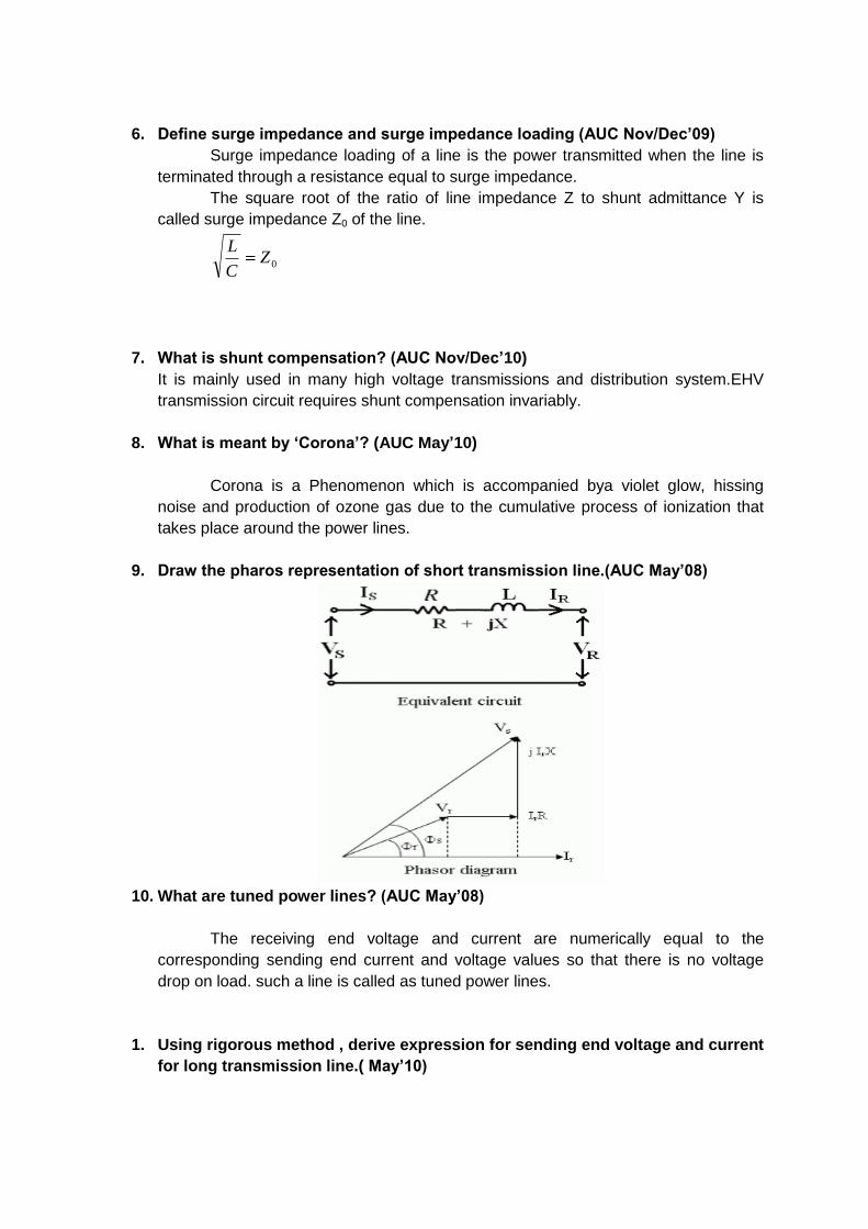
9. Draw the pharos representation of short transmission line.(AUC May’08)
10. What are tuned power lines? (AUC May’08)
The receiving end voltage and current are numerically equal to the
corresponding sending end current and voltage values so that there is no voltage
drop on load. such a line is called as tuned power lines.
1. Using rigorous method , derive expression for sending end voltage and current
for long transmission line.( May’10)

The long lines are the ones for which the length of the line is more than 160
km and the working voltage above 100 kv. Thus for the treatment of such lines
constants are considered uniformly distributed over the whole length of the line and
rigorous methods are employed for solution.
Exact solution of long line
Consider a long transmission lines the series elements are the resistance (r)
and inductance (x) and the shunt elements are the leakage susceptance (b) and the
leakage conductance (g) per unit length thus the series.
Impedance = z=22 XX and y=
22 bg . The leakage currents due to shunt
admittance is maximum at the sending end and decreases continuously towards the
receiving end a t which point it is zero.
Fig above shows an elemental length of the line ds= at a distance of s from the
receiving end. r,x, g and b are the line parameters per unit length. The difference in
voltage between the two ends of the considered section ds is due to the voltage drop in
the series impedance zds where xjyz
Thus dv= Izds, which gives Izds
dv -(1)
Similarly the difference in current is caused by the leakage current through the shunt
element yds where y = 6jg
Thus dI = Vyds
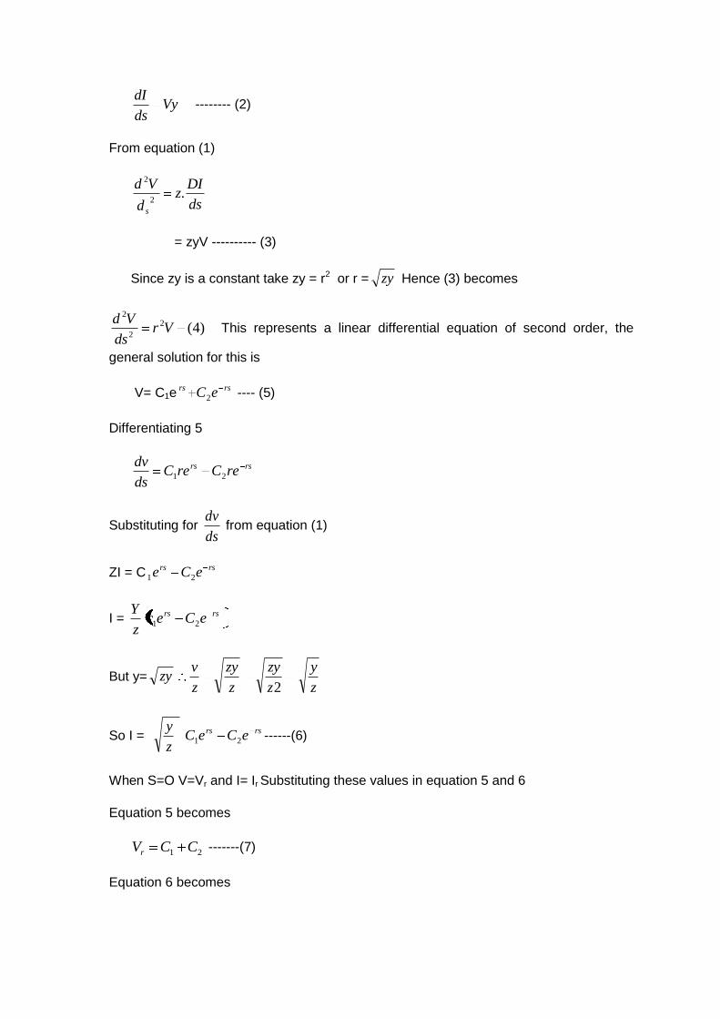
Vyds
dI -------- (2)
From equation (1)
ds
DIz
d
Vd
s
.2
2
= zyV ---------- (3)
Since zy is a constant take zy = r2 or r = zy Hence (3) becomes
)4(2
2
2
Vrds
Vd This represents a linear differential equation of second order, the
general solution for this is
V= C1ersrs eC2 ---- (5)
Differentiating 5
rsrs reCreC
ds
dv21
Substituting for ds
dv from equation (1)
ZI = Crsrs eCe 21
I = rsrs eCec
z
Y21
But y= zyz
y
z
zy
z
zy
z
v
2
So I = z
y rsrs eCeC 21 ------(6)
When S=O V=Vr and I= Ir Substituting these values in equation 5 and 6
Equation 5 becomes
21 CCVr -------(7)
Equation 6 becomes
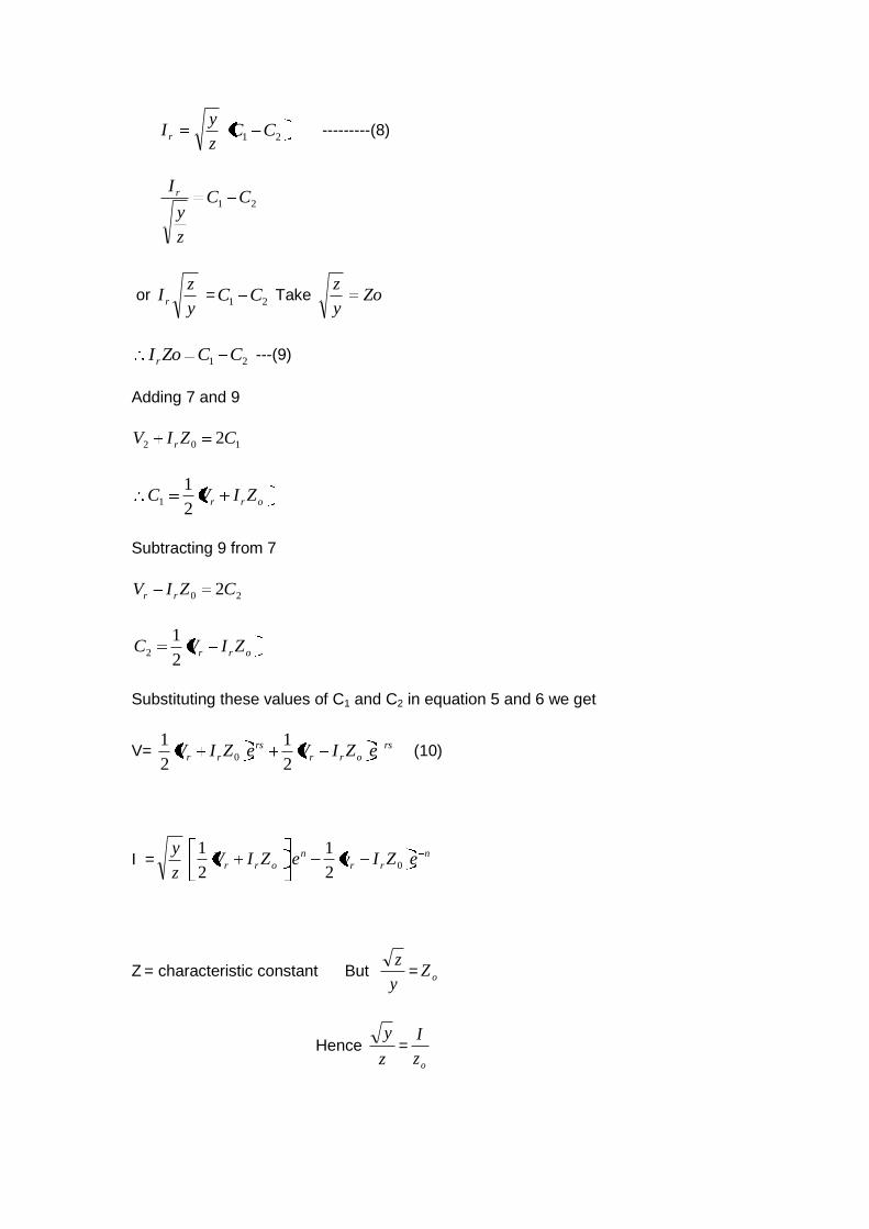
z
yI r 21 CC ---------(8)
21 CC
z
y
I r
or y
zI r =
21 CC Take Zoy
z
21 CCZoIr ---(9)
Adding 7 and 9
102 2CZIV r
orr ZIVC2
11
Subtracting 9 from 7
20 2CZIV rr
orr ZIVC2
12
Substituting these values of C1 and C2 in equation 5 and 6 we get
V= rs
orr
rs
rr eZIVeZIV2
1
2
10 (10)
I =z
y n
rr
n
orr eZIveZIV 02
1
2
1
Z = characteristic constant But y
z= oZ
Hence z
y=
oz
I
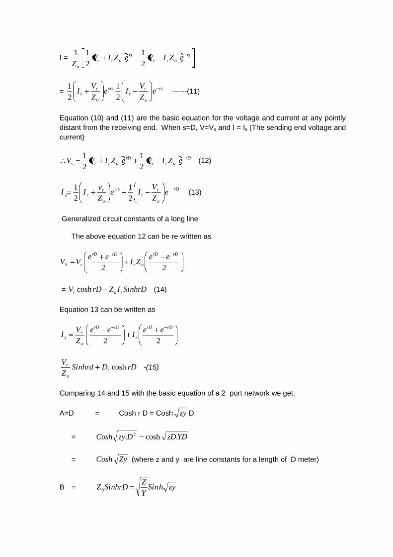
I = rs
orr
rs
orr
o
eZIVeZIVZ 2
1
2
11
= rs
o
rr
srsrr e
Z
VIe
Z
VI
2
1
2
1
0
------(11)
Equation (10) and (11) are the basic equation for the voltage and current at any pointly
distant from the receiving end. When s=D, V=Vs and I = Is (The sending end voltage and
current)
rD
orr
rD
orrs eZIVeZIVV2
1
2
1 (12)
rD
o
rr
rD
o
rrs e
Z
VIe
Z
vII
2
1
2
1 (13)
Generalized circuit constants of a long line
The above equation 12 can be re written as
22
rDrD
or
rDrD
rS
eeZI
eeVV
= SinhrDIZrDV ror cosh (14)
Equation 13 can be written as
22
rDrD
r
rDrD
o
rs
eeI
ee
Z
VI
rDDSinhrdZ
Vr
o
r cosh -(15)
Comparing 14 and 15 with the basic equation of a 2 port network we get.
A=D = Cosh r D = Cosh zy D
= YDzDDzyCosh .cosh. 2
= ZyCosh (where z and y are line constants for a length of D meter)
B = zyhSinY
ZSinhrDZ0
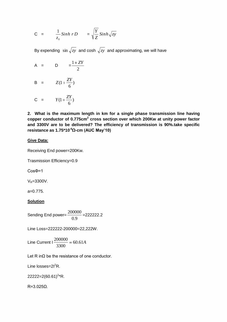
C = DrhSinz0
1 = zyhSin
Z
Y
By expending zysin and cosh zy and approximating, we will have
A = D =2
1 ZY
B = )6
1(ZY
Z
C = )6
1(ZY
Y
2. What is the maximum length in km for a single phase transmission line having
copper conductor of 0.775cm2 cross section over which 200Kw at unity power factor
and 3300V are to be delivered? The efficiency of transmission is 90%.take specific
resistance as 1.75*10-6Ω-cm (AUC May’10)
Give Data:
Receiving End power=200Kw.
Trasmission Efficiency=0.9
CosΦ=1
VR=3300V.
a=0.775.
Solution
Sending End power=9.0
200000=222222.2
Line Loss=222222-200000=22,222W.
Line Current I A61.603300
200000
Let R inΩ be the resistance of one conductor.
Line losses=2I2R.
22222=2(60.61)2*R.
R=3.025Ω.
Ral
a
lR
Km6.1310725.1
755.0025.36
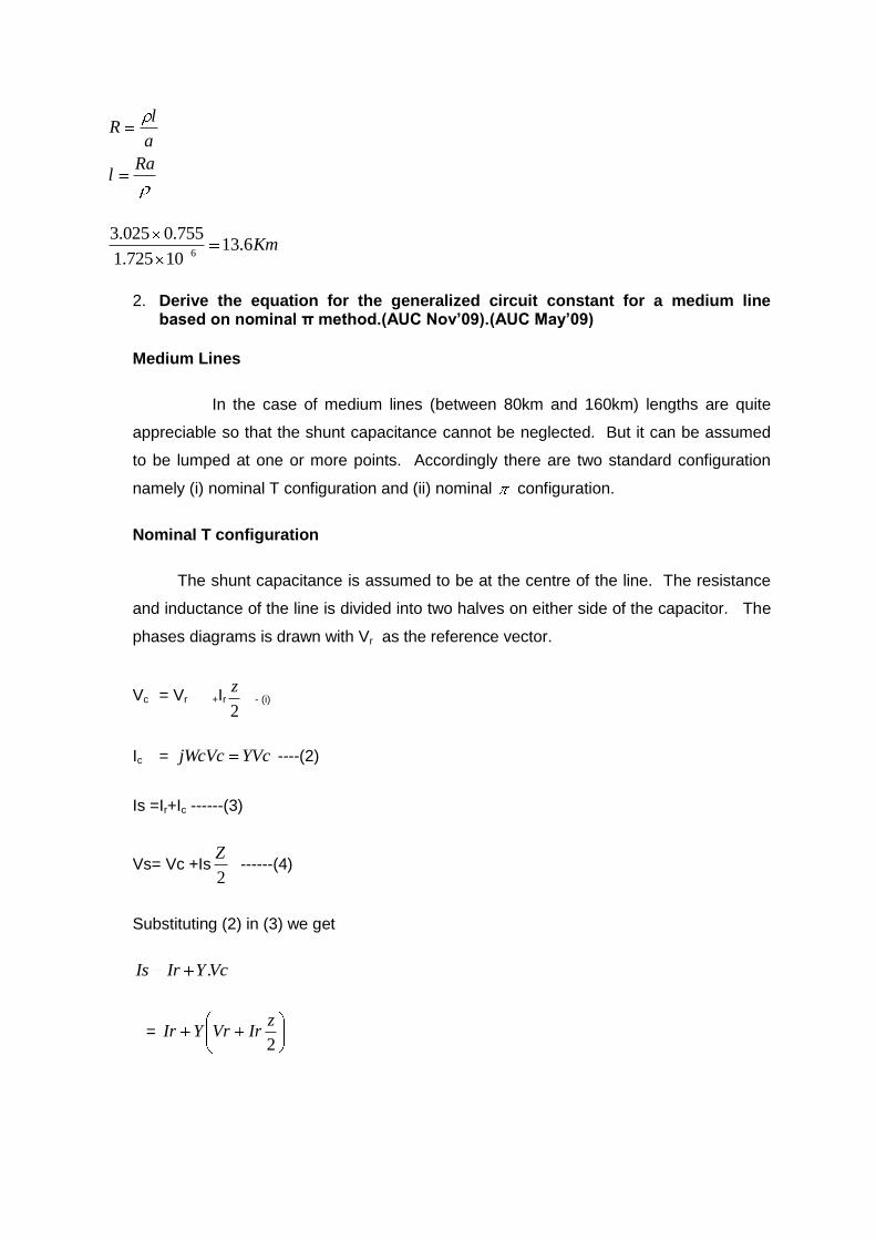
2. Derive the equation for the generalized circuit constant for a medium line based on nominal π method.(AUC Nov’09).(AUC May’09)
Medium Lines
In the case of medium lines (between 80km and 160km) lengths are quite
appreciable so that the shunt capacitance cannot be neglected. But it can be assumed
to be lumped at one or more points. Accordingly there are two standard configuration
namely (i) nominal T configuration and (ii) nominal configuration.
Nominal T configuration
The shunt capacitance is assumed to be at the centre of the line. The resistance
and inductance of the line is divided into two halves on either side of the capacitor. The
phases diagrams is drawn with Vr as the reference vector.
Vc = Vr +Ir2
z - (i)
Ic = YVcjWcVc ----(2)
Is =Ir+Ic ------(3)
Vs= Vc +Is2
Z ------(4)
Substituting (2) in (3) we get
VcYIrIs .
= 2
zIrVrYIr

= Y.Vr + 2
1 YzIr _---(5)
Substituting (5) and (1) in 4 we have
Vs = 2
122
zyIrYVr
zzIrVr
= Vr+ Iryzz
Vryzz
Ir2
1222
=Vr 4222
12yzzz
Iryz
= 42
12yz
zIrYz
Vr (6)
Comparing 5 and 6 with equation for a 2 port net work we have
A= DZy
21
B =4
2
ZyZ =Z
41
Yz
C =Y
II) Nominal Configuration
Here the shunt capacitance is divided in to two parts and assumed to be concentrated on
either end of the line.
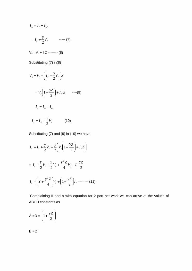
CrrL III
= rr Vy
I2
----- (7)
Vs= Vr + ILZ -------- (8)
Substituting (7) in(8)
ZVy
IVV rrrs2
= ZIyZ
V rr .2
1 ----(9)
csLs III
sLs Vy
II2
(10)
Substituting (7) and (9) in (10) we have
ZIYZ
Vy
Vy
II rrrrs2
122
= 2422
2 YZIV
ZYV
YV
YI rrrrr
rrs IyZ
VZy
YI2
14
2
--------- (11)
Complaining II and 9 with equation for 2 port net work we can arrive at the values of
ABCD constants as
A =D = 2
1Zy
B = Z
C = 4
2
ZYY Y
41
YZ
Note: Y and Z are pharos quantities and in calculation their direction as well as
magnitudes are to be considered.
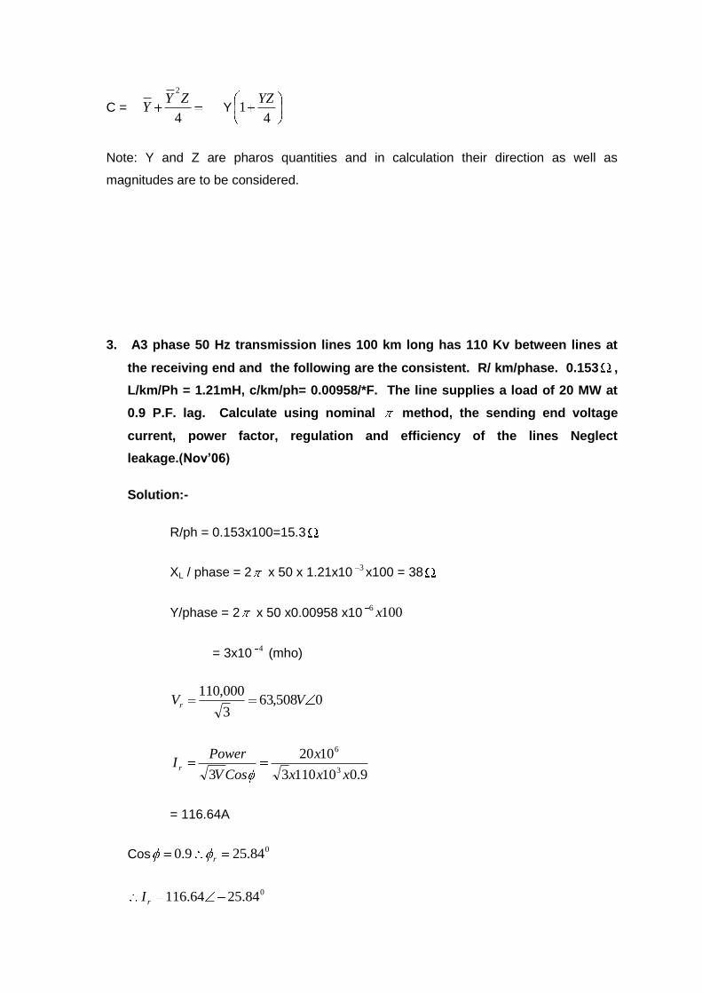
3. A3 phase 50 Hz transmission lines 100 km long has 110 Kv between lines at
the receiving end and the following are the consistent. R/ km/phase. 0.153 ,
L/km/Ph = 1.21mH, c/km/ph= 0.00958/*F. The line supplies a load of 20 MW at
0.9 P.F. lag. Calculate using nominal method, the sending end voltage
current, power factor, regulation and efficiency of the lines Neglect
leakage.(Nov’06)
Solution:-
R/ph = 0.153x100=15.3
XL / phase = 2 x 50 x 1.21x103x100 = 38
Y/phase = 2 x 50 x0.00958 x10 1006 x
= 3x10⁴ (mho)
0508,633
000,110VVr
9.0101103
1020
3 3
6
xxx
x
CosV
PowerI r
= 116.64A
Cos084.259.0 r
084.2564.116rI
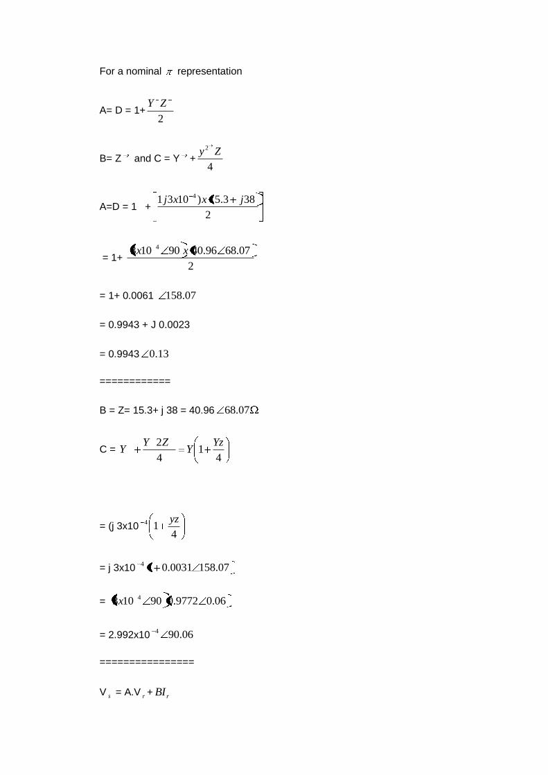
For a nominal representation
A= D = 1+2
ZY
B= Z and C = Y +4
2 Zy
A=D = 1 +2
383.15)1031 4 jxxj
= 1+ 2
07.6896.4090103 4 xx
= 1+ 0.0061 07.158
= 0.9943 + J 0.0023
= 0.9943 13.0
============
B = Z= 15.3+ j 38 = 40.96 07.68
C = 4
14
2 YzY
ZYY
= (j 3x10⁴
14 yz
= j 3x10 07.1580031.014
= 06.09772.090103 4x
= 2.992x10 06.904
================
V s = A.V r + rBI

=o.9943 84.2564.11607.6896.4006350813.0 xx
`= 63,146 23.4257.477713.0
= 63,145,84 +j 143.27+3537.565+j3211
= 66683.405 + j 3354.315
= 66767.72088.2
Sending end voltage = 66767.7x 3 = 115.65 K.V.- Am
I rrs DICv
= (2.992x10 84.2564.11613.09943.0063503)06.904 x
= 19 71.2598.11506.90
= - 0.02 + j19+104.5 -j 50.314
= 109.07 68:16 A
Sending end current = 109.07 Ans
=======
Sending end power factor angle = 16.68+2.88
= 19.56
Sending end power factor = cos 19.56 = 0.942 Ans
==========
% Regulation = 10063508
6350872.66767100 xx
V
VV
r
rs
5.13% ---- ans
Out put power = 20 MW
Input power = ss IV3 cos s =3x66767.72x109.07x0.942
=20.579936 MW
Efficiency = 100936,579,20
10000,20x
x
= 97.2% - Ans
=======
4. What is shunt compensation? Discuss the types of static VAR system used in
EHV transmission.(Nov’09)
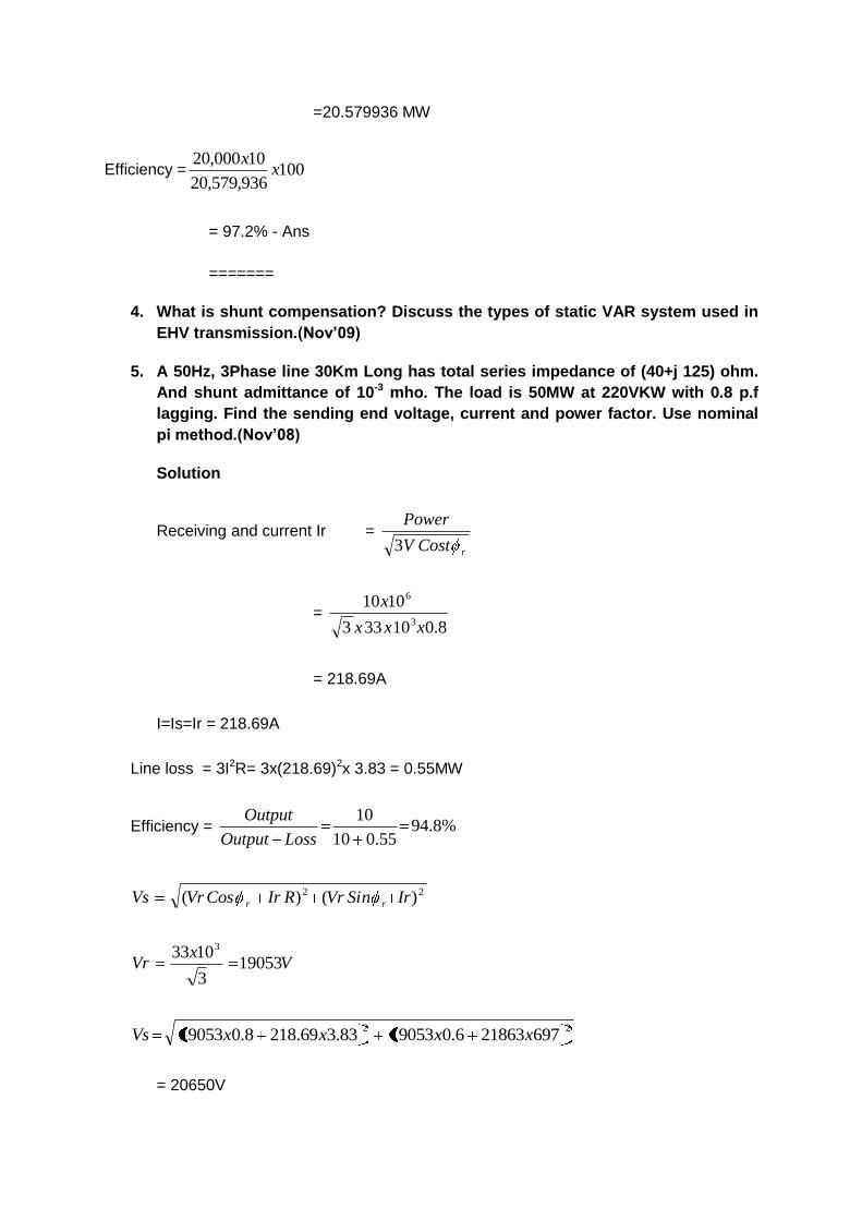
5. A 50Hz, 3Phase line 30Km Long has total series impedance of (40+j 125) ohm.
And shunt admittance of 10-3 mho. The load is 50MW at 220VKW with 0.8 p.f
lagging. Find the sending end voltage, current and power factor. Use nominal
pi method.(Nov’08)
Solution
Receiving and current Ir =
rCostV
Power
3
= 8.010333
10103
6
xxx
x
= 218.69A
I=Is=Ir = 218.69A
Line loss = 3I2R= 3x(218.69)2x 3.83 = 0.55MW
Efficiency = %8.9455.010
10
LossOutput
Output
22 )()( IrSinVrRIrCosVrVs rr
Vx
Vr 190533
1033 3
22697218636.01905383.369.2188.019053 xxxxVs
= 20650V

Regulation = 10019053
1905320650100 xx
Vr
VrVs
= 8.38%
=====
6. Explain the Corona. (Nov ‘ 09)
Electric-power transmission practically deals in the bulk transfer of electrical energy, from generating stations situated many kilometers away from the main consumption centers or the cities. For this reason the long distance transmission cables are of utmost necessity for effective power transfer, which in-evidently results in huge losses across the system. Minimizing those has been a major challenge for power engineers of late and to do that one should have a clear understanding of the type and nature of losses. One of them being the corona effect in power system, which has a predominant role in reducing the efficiency of EHV (extra high voltage lines) which we are going to concentrate on, in this article.
What is corona effect in power system and why it occurs?
For corona effect to occur effectively, two factors here are of prime importance as mentioned below:- 1) Alternating potential difference must be supplied across the line. 2) The spacing of the conductors, must be large enough compared to the line diameter.
Corona Effect in Transmission Line
When an alternating current is made to flow across two conductors of the transmission line whose spacing is large compared to their diameters, then air surrounding the conductors (composed of ions) is subjected to di-electric stress. At low values of supply end voltage, nothing really occurs as the stress is too less to ionize the air outside. But when the potential difference is made to increase beyond some threshold value of around 30 kV known as the critical disruptive voltage, then the field strength increases and then the air surrounding it experiences stress high enough to be dissociated into ions making the atmosphere conducting. This results in electric discharge around the conductors due to the flow of these ions, giving rise to a faint luminescent glow, along with the hissing sound accompanied by the liberation of ozone, which is readily identified due to its characteristic odor. This phenomena of electrical discharge occurring in transmission line for high values of voltage is known as the corona effect in power system. If the voltage across the lines is still increased the glow becomes more and more intense along with hissing noise, inducing very high power loss into the system which must be accounted for.
Factors affecting corona effect in power system.

As mentioned earlier, the line voltage of the conductor is the main determining factor for corona in transmission lines, at low values of voltage (lesser than critical disruptive voltage) the stress on the air is too less to dissociate them, and hence no electrical discharge occurs. Since with increasing voltage corona effect in a transmission line occurs due to the ionization of atmospheric air surrounding the cables, it is mainly affected by the conditions of the cable as well as the physical state of the atmosphere. Let us look into these criterion now with greater details:-
Atmospheric conditions for corona in transmission lines.
It has been physically proven that the voltage gradient for di-electric breakdown of air is directly proportional to the density of air. Hence in a stormy day, due to continuous air flow the number of ions present surrounding the conductor is far more than normal, and hence its more likely to have electrical discharge in transmission lines on such a day, compared to a day with fairly clear weather. The system has to designed taking those extreme situations into consideration.
Condition of cables for corona in transmission line
This particular phenomena depends highly on the conductors and its physical condition. It has an inverse proportionality relationship with the diameter of the conductors. i.e. with the increase in diameter, the effect of corona in power system reduces considerably. Also the presence of dirt or roughness of the conductor reduces the critical breakdown voltage, making the conductors more prone to corona losses. Hence in most cities and industrial areas having high pollution, this factor is of reasonable importance to counter the ill effects it has on the system.
7. Explain surge impedance loading with respect to an over head transmission lines.(june’10)
Characteristic Impedance
Y
ZZ0 is called the characteristic impedance. The value is independent of the line
length. But it depends upon the radius and spacing of the conductors. The
characteristic impedance Z0 is the impedance offered by the line to the propagation of a
current or voltage wave. For a lossless line r=0 and g=0
Hence 00 ;ZC
L
c
e
f
xZ is also called the natural impedance of the line.
The value of Z0 can be reduced by using shunt capacitance, there by increasing the
value of C. But to improve system stability series capacitors are used, which also
reduces voltage drop.

Natural load or Surge Impedance Load (SIL)
It is defined as the load at which the inductive volt amperes of the line is equal and
opposite to the capacitive volt amperes.
V C in the current through the capacitance and V is the voltage across it. Then volt
amperes = V(V C)=V2 C I is the current through the inductance, then I L is the
voltage drop. Then volt amperes across the inductance = (IWL)xI=I2WL when the two
are equal V2WC=I2WL
Then 0ZC
L
WC
WL
I
V
At this load, ratio of voltage to current is equal to Z0 the surge impedance which is
purely resistive. Hence the voltage and current are in phase at all points in the line. The
surge impedance loading of a line is defined as the load delivered by it to a purely
resistive load equal to the surge impedance.
)1(sin. 0 CosceVIPphasePerLSI
=0
2
0
)(Z
V
Z
VV watts/phase
=0
23
Z
V
=3
(2
0
VLVSince
Z
VL )
Related Documents