J.MONISHA, AP/EEE MAHALAKSHMI ENGINEERING COLLEGE TRICHY- 621213 Page 1 MAHALAKSHMI ENGINEERING COLLEGE TIRUCHIRAPALLI – 621213 EE-2401 POWER SYSTEM OPERATION AND CONTROL UNIT II REAL POWER -FREQUENCY CONTROL TWO MARKS 1. What is the major control loops used in large generators? The major control loops used in large generators are Automatic voltage regulator (AVR) Automatic load frequency control (ALFC). 2. What is the use of secondary loop? Secondary loop is used to maintain the fine adjustment of the frequency, and also by reset action maintains proper MW interchange with other pool members. This loop is insensitive to rapid load and frequency changes but focuses instead on drift like changes which take place over periods of minutes. 3. What is the advantage of AVR loop over ALFC? The advantage of AVR loop over ALFC is very fast and therefore there is a tendency for the AVR dynamics to settle down before they can make themselves felt in the slower load frequency control channel. 4. What is the exciter? The exciter is the main component in AVR loop. It delivers the DC power to the generator field. It must have adequate power capacity and sufficient speed of response (rise time less than 0.1 sec). 5. Specify the disadvantage of ALFC loop. The disadvantage of ALFC loop is that it will control only during normal changes in load and frequency. It is unable to provide adequate control during emergency situations, when large MW imbalances occur.

Welcome message from author
This document is posted to help you gain knowledge. Please leave a comment to let me know what you think about it! Share it to your friends and learn new things together.
Transcript

J.MONISHA, AP/EEE MAHALAKSHMI ENGINEERING COLLEGE TRICHY- 621213 Page 1
MAHALAKSHMI ENGINEERING COLLEGE TIRUCHIRAPALLI – 621213
EE-2401 POWER SYSTEM OPERATION AND CONTROL
UNIT II
REAL POWER -FREQUENCY CONTROL
TWO MARKS
1. What is the major control loops used in large generators?
The major control loops used in large generators are
Automatic voltage regulator (AVR)
Automatic load frequency control (ALFC).
2. What is the use of secondary loop?
Secondary loop is used to maintain the fine adjustment of the frequency, and also by
reset action maintains proper MW interchange with other pool members. This loop is insensitive
to rapid load and frequency changes but focuses instead on drift like changes which take place
over periods of minutes.
3. What is the advantage of AVR loop over ALFC?
The advantage of AVR loop over ALFC is very fast and therefore there is a tendency for
the AVR dynamics to settle down before they can make themselves felt in the slower load
frequency control channel.
4. What is the exciter?
The exciter is the main component in AVR loop. It delivers the DC power to the
generator field. It must have adequate power capacity and sufficient speed of response (rise
time less than 0.1 sec).
5. Specify the disadvantage of ALFC loop.
The disadvantage of ALFC loop is that it will control only during normal changes in load
and frequency. It is unable to provide adequate control during emergency situations, when large
MW imbalances occur.

J.MONISHA, AP/EEE MAHALAKSHMI ENGINEERING COLLEGE TRICHY- 621213 Page 2
6. What is the function of AVR?
The function of the AVR is to provide constancy of the generator terminal voltage
during normal, small and slow changes in the load.
7. Explain about static AVR loop.
In a static AVR loop, the execution power is obtained directly from the generator
terminals or from the station service bus. The AC power is rectified by thyristor bridges and fed
into the main generator field via slip rings. Static exciters are very fast and contribute to
improved transient stability.
8. Write the static performance of AVR loop.[AUC APR/MAY 2011]
Static performance of AVR loop is to regulate the terminal |V| to within required static
accuracy limit, have sufficient speed of response and be stable.
9. What is the disadvantage of high loop gain? How it is to be eliminated?
The disadvantage of high loop gain is that it causes undesirable dynamic response,
possibly instability. By adding series AND/OR feedback stability compensation to the AVR loop,
this conflicting situation can be resolved.
10. What are the effects of generator loading in AVR loop?
Effects of generator loading in AVR loop is given below. Added load does not change
the basic features of the AVR loop; it will however affect the values of both gain factor Kf and
the field constant. High loading will make the generator work at higher magnetic saturation
levels. This means smaller changes in |E| for incremental increases in if, translating into the
reduction of KF. The field time constant will likewise decrease as generator loading closing the
armature current paths. This circumstance permits the formation of transient stator currents the
existence of which yields a lower effective field induction.
11. What are the functions of ALFC? [AUC NOV/DEC 2013]
Function of ALFC’s is to maintain desired MW output of a generator unit and assist in
controlling the frequency of large interconnection. The ALFC also helps to keep the net
interchange of power between pool members at predetermined values. Control should be
applied in such a fashion that highly differing response characteristics of units of various types
are recognized. Also unnecessary power output changes should be kept at a minimum in order
to reduce wear of control valves.
12. How is the real power in a power system controlled? [AUC APRIL/MAY 2011]
The real power in a power system is being controlled by controlling the driving torque of
the individual turbines of the system.
13. What is the need for large mechanical forces in speed-governing system?
J.MONISHA, AP/EEE MAHALAKSHMI ENGINEERING COLLEGE TRICHY- 621213 Page 3
Very large mechanical forces are needed to position the main valve against the high
stream pressure and these forces are obtained via several stages of hydraulic amplifiers.
14. What are the inputs of governor?
The governor has two inputs. They are,
a. Changes ∆pref in the reference power setting.
b. Change ∆f in the sped of frequency of the generator, as measured by ∆xB.
15. What is the control area?
It is possible to divide an extended power system into sub-areas in which the generators
are tightly coupled together so as to form a coherent group (i.e) all the generators respond in
unison to changes in load or speed changer settings. Such a coherent area is called a control
area in which the frequency is assumed to be the same throughout in static as well as dynamic
conditions.
16. What is selective frequency control?
The common method of operating a large interconnected system assigns frequency
control to a central system, the other systems then controlled on the basis of automatic control
are used in three different ways. One of these is known as selected frequency control.
17. What are the parts of speed governing system?
The parts of speed governing system are,
a. Speed governor
b. Linkage mechanism
c. Hydraulic amplifier
d. Speed changer
18. Write about speed governor and speed changer. [AUC APRIL/MAY 2011] [AUC
NOV/DEC 2008]
Speed governor is a fly-ball type of speed governor and constitutes the heart of the system as it
senses the change in speed or frequency with the increase in speed the fly-ball move outwards
and the linkage mechanism move downwards.
19. Write about hydraulic amplifier.
Hydraulic amplifier consists of a main piston and pilot valve. Low power level pilot valve
movement is converted into high power level piston valve movement which is necessary to open
or close the steam valve against high pressure steam.
J.MONISHA, AP/EEE MAHALAKSHMI ENGINEERING COLLEGE TRICHY- 621213 Page 4
20. Define inertia constant
Inertia constant, H is defined as the ratio of kinetic energy stored in the rotar to the MVA
rating of the generator.
H = wK.E / Pr
H- Inertia constant
wK.E - Kinectic energy
Pr - Rated MVA of the generator
21. How the single area controlled system is protected?
The single area controlled system is protected by the following three ways,
a. ‘Borrowed’ kinetic energy from the rotating machines of the system.
b. ‘Released’ customer load.
c. Increased generation.
22. What is damping factor?
Damping factor is known as frequency co-efficient of load and characterizes the
frequency characteristic of the load. It is usually expressed in percent of connected load per 0.1
Hz and the typical values lie between 0.3 to 0.5% per 0.1 Hz. It is denoted as D = dPD . The
unit is MW per Hz.
23. How is the real power in a power system controlled?
The real power in a power is being controlled by controlling the drinking torques of
the individual turbines of the system.
24. What is the need for very large mechanical forces in speed – governing system?
Very large mechanical forces are needed to position the main value (or gate) against,
the high steam (or water) pressure, and these forces are obtained via several stages of
hydraulic amplifiers.
25. Write the tie-line power deviation equation in terms of frequency
∆Ptie ,1 = 2П T12 [ ʃ∆f1 dt - ʃ∆f2 dt ]
26. Define per unit droop
The per unit droop or speed regulation R of the generating unit is defined as the
magnitude of the change in steady state speed, expressed in p.u of rated speed, when the
output of the unit gradually reduced from 1.0 p.u rated power to zero.
P.u regulation, Rp.u = (f2− f1 )/fr
P GRP r
p.u
J.MONISHA, AP/EEE MAHALAKSHMI ENGINEERING COLLEGE TRICHY- 621213 Page 5
Where, f2 = frequency at no-load,Hz
f1 = frequency at rated megawatt output, PGR
27.What is Area control error(ACE)? [AUC NOV/DEC 2007]
ACE is the change in frequency which when used in integral control loop forced the
steady state frequency error to zero.
ACE = ∆𝑃𝑡𝑖𝑒 + b.∆f p.u MW (for multi area system)
ACE = ∆f (for single area system)
Where, b= Area frequency bias
∆𝑃𝑡𝑖𝑒 = Change in tie − line power
∆f = change in frequency
28. Give the conditions for proper synchronizing of alternator? [AUC NOV/DEC 2012]
[AUC NOV/DEC 2013]
The conditions for proper synchronizing are:
The terminal voltage of the incoming machine must be exactly equal to that of the others
or of the bus bars connecting them.
The speed of the incoming machine must be such that its frequency equals to the bus
bar frequency
29. What are the types of automatic load frequency control for interconnected power
system? [AUC NOV/DEC 2012]
Flat frequency control
Flat Tie-line control
Fequency bias tie-line control
J.MONISHA, AP/EEE MAHALAKSHMI ENGINEERING COLLEGE TRICHY- 621213 Page 6
16 MARKS
1.Explain the fundamentals and modeling of speed governing mechanism :[AUC
NOV/DEC 2008] [AUC NOV/DEC 2013] [AUC MAY/JUN 2013]
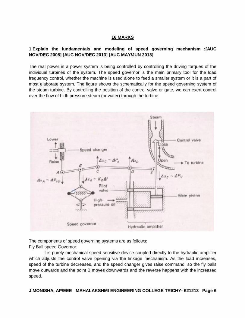
The real power in a power system is being controlled by controlling the driving torques of the
individual turbines of the system. The speed governor is the main primary tool for the load
frequency control, whether the machine is used alone to feed a smaller system or it is a part of
most elaborate system. The figure shows the schematically for the speed governing system of
the steam turbine. By controlling the position of the control valve or gate, we can exert control
over the flow of hidh pressure steam (or water) through the turbine.
The components of speed governing systems are as follows:
Fly Ball speed Governor:
It is purely mechanical speed-sensitive device coupled directly to the hydraulic amplifier
which adjusts the control valve opening via the linkage mechanism. As the load increases,
speed of the turbine decreases, and the speed changer gives raise command, so the fly balls
move outwards and the point B moves downwards and the reverse happens with the increased
speed.
J.MONISHA, AP/EEE MAHALAKSHMI ENGINEERING COLLEGE TRICHY- 621213 Page 7
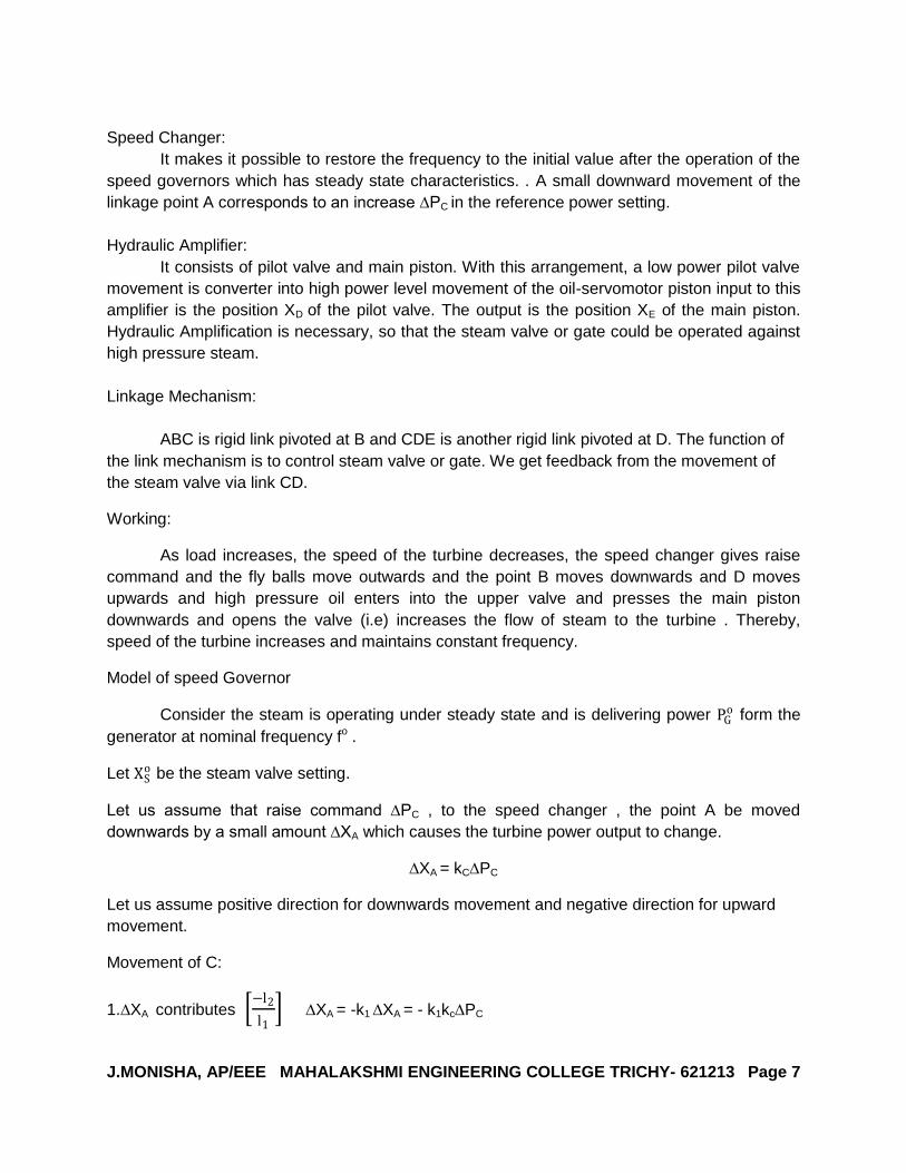
Speed Changer:
It makes it possible to restore the frequency to the initial value after the operation of the
speed governors which has steady state characteristics. . A small downward movement of the
linkage point A corresponds to an increase ∆PC in the reference power setting.
Hydraulic Amplifier:
It consists of pilot valve and main piston. With this arrangement, a low power pilot valve
movement is converter into high power level movement of the oil-servomotor piston input to this
amplifier is the position XD of the pilot valve. The output is the position XE of the main piston.
Hydraulic Amplification is necessary, so that the steam valve or gate could be operated against
high pressure steam.
Linkage Mechanism:
ABC is rigid link pivoted at B and CDE is another rigid link pivoted at D. The function of
the link mechanism is to control steam valve or gate. We get feedback from the movement of
the steam valve via link CD.
Working:
As load increases, the speed of the turbine decreases, the speed changer gives raise
command and the fly balls move outwards and the point B moves downwards and D moves
upwards and high pressure oil enters into the upper valve and presses the main piston
downwards and opens the valve (i.e) increases the flow of steam to the turbine . Thereby,
speed of the turbine increases and maintains constant frequency.
Model of speed Governor
Consider the steam is operating under steady state and is delivering power PGo form the
generator at nominal frequency fo .
Let XSo be the steam valve setting.
Let us assume that raise command ∆PC , to the speed changer , the point A be moved
downwards by a small amount ∆XA which causes the turbine power output to change.
∆XA = kC∆PC
Let us assume positive direction for downwards movement and negative direction for upward
movement.
Movement of C:
1.∆XA contributes −l2
l1 ∆XA = -k1 ∆XA = - k1kc∆PC
J.MONISHA, AP/EEE MAHALAKSHMI ENGINEERING COLLEGE TRICHY- 621213 Page 8
2.Increase in frequency ∆f causes the fly balls to move outwards so that B moves downwards
by a proportional amount k2∆f.
∆XC = -k1kC∆PC + k2∆f (1)
Movement of D:
It is contributed by ∆XC and ∆XE . The movement ∆XD is the amount by which the pilot valve
opens, thereby moving the main piston and opening the steam valve by ∆XE .
∆XD = 𝑙4
𝑙3+𝑙4 ∆XC +
𝑙4
𝑙3+𝑙4 ∆XE
= k3∆XC+k4∆XE (2)
Movement of ∆XE:
The volume of oil admitted to the cylinder is thus proportional to the line integral of ∆XD
∆XE = k5 −∆𝑋𝐷 𝑡
0𝑑𝑡 (3)
Taking the Laplace transform of equation 1,2,3
∆XC(s) = -k1kC∆PC(s) + k2∆F(s) (4)
∆XD(s) = k3∆XC(s) +k4∆XE(s) (5)
∆XE(s) = −𝑘5
𝑠 ∆XD(s) (6)
Substitute eqn. 5 in 6, we get,
∆XE(s) = −𝑘5
𝑠 [k3∆XC(s) +k4∆XE(s) ]
∆XE(s) 1 +𝑘4𝑘5
𝑠 =
−𝑘5𝑘3
𝑠 ∆XC(s) (7)
Substitute eqn. 4 in 7 , we get
∆XE(s) 1 +𝑘4𝑘5
𝑠 =
−𝑘5𝑘3
𝑠 [-k1kC∆PC(s) + k2∆F(s)]
∆XE(s) 𝑠+𝑘4𝑘5
𝑠 =
𝑘5𝑘3𝑘1𝑘𝑐 ∆Pc s − k2k5k3∆F(s)
𝑠
∆XE(s) = 𝑘5𝑘3𝑘1 𝑘𝑐 ∆𝑃𝐶(𝑠)−
𝑘2𝑘1𝑘𝑐
∆F(s)
𝑘4𝑘5 1+ 𝑠
𝑘4𝑘5
= 𝑘3𝑘1𝑘𝑐
𝑘4
∆𝑃𝐶(𝑠)− 𝑘2
𝑘1𝑘𝑐 ∆F(s)
1+ 𝑠
𝑘4𝑘5
J.MONISHA, AP/EEE MAHALAKSHMI ENGINEERING COLLEGE TRICHY- 621213 Page 9
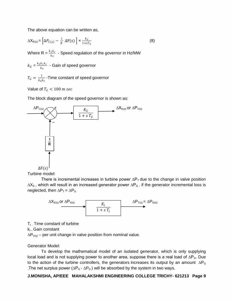
The above equation can be written as,
∆XE(s) = ∆𝑃𝐶(𝑠) − 1
𝑅 ∆F(s) ×
𝑘𝐺
1+𝑠𝑇𝐺 (8)
Where R = 𝑘1𝑘𝑐
𝑘2 - Speed regulation of the governor in Hz/MW
𝑘𝐺 = 𝑘3𝑘1𝑘𝑐
𝑘4 - Gain of speed governor
𝑇𝐺 = 1
𝑘4𝑘5 -Time constant of speed governor
Value of 𝑇𝐺 < 100 𝑚 𝑠𝑒𝑐
The block diagram of the speed governor is shown as:
∆PC(s) + ∆XE(s) or ∆PV(s)
∆F(s)
Turbine model:
There is incremental increases in turbine power ∆PT due to the change in valve position
∆XE , which will result in an increased generator power ∆PG . if the generator incremental loss is
neglected, then ∆PT = ∆PG
∆XE(s) or ∆PV(s) ∆PT(s) = ∆PG(s)
Tt - Time constant of turbine
kt – Gain constant
∆PV(s) – per unit change in valve position from nominal value.
Generator Model:
To develop the mathematical model of an isolated generator, which is only supplying
local load and is not supplying power to another area, suppose there is a real load of ∆PD. Due
to the action of the turbine controllers, the generators increases its output by an amount ∆PG
.The net surplus power (∆PG - ∆PD ) will be absorbed by the system in two ways.
𝐾𝐺
1 + 𝑠 𝑇𝐺
𝐾𝑡
1 + 𝑠 𝑇𝑡

J.MONISHA, AP/EEE MAHALAKSHMI ENGINEERING COLLEGE TRICHY- 621213 Page 10
1. By increasing the kinetic energy in the rotar at the rate 𝑑
𝑑𝑡 (𝑤𝐾.𝐸)
wK.Eo
= H ×Pr kW sec
wK.Eo =
J ωo2
2 = wK.Eo α f0
2 (9)
wK.E α (f0 + ∆f)2 (10)
Divide the eqn. 10 by 9 ,we get,
wK.E = 𝑤𝐾.𝐸𝑜
𝑓0+ ∆𝑓
𝑓0
2 = 𝑤𝐾.𝐸
𝑜 1 +∆𝑓
𝑓0
2
= 𝑤𝐾.𝐸𝑜 1 +
2∆𝑓
𝑓0 +
∆𝑓2
𝑓02
= 𝑤𝐾.𝐸𝑜 1 +
2∆𝑓
𝑓0 (Neglecting second order term)
Rate of change in kinetic energy 𝑑𝑤𝐾 .𝐸
𝑑𝑡 =
2 𝑤𝐾 .𝐸𝑜
𝑓0 𝑑
𝑑𝑡 (∆𝑓) (11)
Substitute wK.Eo ,
𝑑𝑤𝐾 .𝐸
𝑑𝑡 =
2𝐻𝑃𝑟
𝑓0 𝑑
𝑑𝑡 (∆𝑓) (12)
2.As the frequency changes, the motor load changes being sensitive to speed.
Rate of change of load with respect to frequency 𝜕𝑃𝐷
𝜕𝑓 = B
B = Damping coefficient in MW/Hz.
Value of B is positive for motor load.
∆PG - ∆PD = B ∆f
On writing power balance equation equation,
∆PG - ∆PD = 2𝐻𝑃𝑟
𝑓0 𝑑
𝑑𝑡 ∆𝑓 + B ∆f
Dividing by Pr, we get,
∆PG(p.u) - ∆PD(p.u) = 2𝐻
𝑓0 𝑑
𝑑𝑡 ∆𝑓 + B ∆f
Taking laplace transform on both sides,we get,
∆PG(s) - ∆PD(s) = 2𝐻𝑠
𝑓0 ∆F(𝑠) + B ∆F(s)
∆PG(s) - ∆PD(s) =∆F(s) 2𝐻𝑠
𝑓0 + B
∆F(s) = ∆PG (s)− ∆PD (s)
𝐵 1+ 2𝐻𝑠
𝐵𝑓0

J.MONISHA, AP/EEE MAHALAKSHMI ENGINEERING COLLEGE TRICHY- 621213 Page 11
∆F(s) = ∆PG(s) - ∆PD(s) 𝑘𝑃
1+𝑠𝑇𝑃 (14)
𝑘𝑃 = 1
𝐵 = Power system gain
𝑇𝑃 = 2𝐻
𝐵𝑓0 = Power system time constant. The block diagram for generator load model is given
as:
Model of load frequency control of a single area system:
Combining the governor model, turbine model , and generator load model ,we get the complete
block diagram representation of LFC of an isolated power system is shown in figure given
below:
2. Explain the speed load characteristics (Load sharing between two synchronous
machine in parallel ): [AUC NOV/DEC 2013]
Consider the boiler-turbine generator combination of a thermal generating unit. The
function of the speed governor is to monitor the speed and to control the throttle valves which
adjust steam flow into the turbine. To permit parallel operation of units, the speed vs power
output governing characteristics of each unit has drooped is shown in the figure given below:
J.MONISHA, AP/EEE MAHALAKSHMI ENGINEERING COLLEGE TRICHY- 621213 Page 12
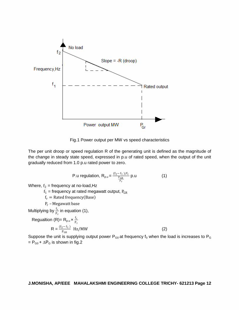
Fig.1 Power output per MW vs speed characteristics
The per unit droop or speed regulation R of the generating unit is defined as the magnitude of
the change in steady state speed, expressed in p.u of rated speed, when the output of the unit
gradually reduced from 1.0 p.u rated power to zero.
P.u regulation, Rp.u = (f2− f1 )/fr
P GRP r
p.u (1)
Where, f2 = frequency at no-load,Hz
f1 = frequency at rated megawatt output, PGR
fr = Rated frequency Base
Pr – Megawatt base
Multiplying by fr
Pr in equation (1),
Regualtion (R)= Rp.u × fr
Pr
R = (f2− f1 )
PGR Hz/MW (2)
Suppose the unit is supplying output power PG0 at frequency f0 when the load is increases to PG
= PG0 + ∆PG is shown in fig.2

J.MONISHA, AP/EEE MAHALAKSHMI ENGINEERING COLLEGE TRICHY- 621213 Page 13
Fig.2 Speed –load characteristics
From fig.2
Slope = ∆𝐹
∆𝑃𝐺 = -R
∆f=-R. ∆𝑃𝐺 = 𝑅𝑝 .𝑢 𝑓𝑟
𝑃𝑟 ∆𝑃𝐺 𝐻𝑧
Due to the supplementary control action of the speed changer, speed control mechanism can
parallel-shift the regulation characteristics to final position. When two generating units are
operating in parallel on the system, on their speed –droop characteristics low load changes are
shared among them in the steady state and to operate to a common frequency.
The changes in the outputs of the units are given as:
Unit 1, ∆𝑃𝐺1 = −𝑃𝑟1
𝑅𝑝 .𝑢1 ×
∆𝑓
𝑓𝑟 𝑀𝑊 (3)
Unit 2, ∆𝑃𝐺2 = −𝑃𝑟2
𝑅𝑝 .𝑢2 ×
∆𝑓
𝑓𝑟 𝑀𝑊 (4)
Adding eqn. 3 and 4
Total load change in output ∆𝑃𝐺 = ∆𝑃𝐺1 + ∆𝑃𝐺2

J.MONISHA, AP/EEE MAHALAKSHMI ENGINEERING COLLEGE TRICHY- 621213 Page 14
= ∆𝑓
𝑓𝑟 𝑃𝑟1
𝑅𝑝𝑢 1 +
𝑃𝑟2
𝑅𝑝𝑢 2 (5)
The system frequency change ∆𝑓
𝑓𝑟 =
−∆𝑃∆𝑓
𝑓𝑟 𝑃𝑟1
𝑅𝑝𝑢 1 +
𝑃𝑟2𝑅𝑝𝑢 2
𝑝. 𝑢
∆𝑓 =−∆𝑃 𝑓𝑟
𝑃𝑟1
𝑅𝑝𝑢 1 +
𝑃𝑟2𝑅𝑝𝑢 2
= −∆𝑃
1
𝑅1+
1
𝑅2
The additional ∆𝑃𝐺𝑟𝑜 =
𝑃𝑟𝑖𝑅𝑖𝑝 .𝑢
∆𝑃
𝑃𝑟1
𝑅𝑝 .𝑢1 +
𝑃𝑟2𝑅𝑝𝑢 2
MW
Thus the coordinated control of the set points of the speed governor is to bring all the units at
desired frequency f0 and to achieve any desired load division within the capabilities of the
generating units.
3.Explain the steady state or static response of single area system? [AUC NOV/DEC 2013
AUC APR/MAY 2011] [AUC MAY/JUNE 2009]
Consider the speed changer has a fixed setting. Under the condition ∆PC =0 and the load
demand changes. This is known as free governor operation. The block diagram is shown in fig.1
is drawn from substituting ∆PC =0 in fig.1
Fig.1
Using the block diagram reduction technique, the block diagram is shown in Fig.2

J.MONISHA, AP/EEE MAHALAKSHMI ENGINEERING COLLEGE TRICHY- 621213 Page 15
-
∆F(s)=
𝑘𝑃1+𝑠𝑇𝑃
1+ 𝑘𝑃
1+𝑠𝑇𝑃×
𝑘𝐺𝑘𝑡𝑅 1+ 𝑠𝑇𝐺 1+ 𝑠𝑇𝑡
−∆PD s
∆F(s) = 𝑘𝑃
1+ 𝑠𝑇𝑃+ 𝑘𝑃𝑘𝐺𝑘𝑡
𝑅 1+ 𝑠𝑇𝐺 1+ 𝑠𝑇𝑡 −∆PD s
For a step load changes −∆PD s = ∆PD
𝑠
∆F(s) = 𝑘𝑃
1+ 𝑠𝑇𝑃+ 𝑘𝑃𝑘𝐺𝑘𝑡
𝑅 1+ 𝑠𝑇𝐺 1+ 𝑠𝑇𝑡 ×
∆PD
𝑠
Applying final value theorem,
∆fstat = 𝐿𝑡 s. ∆F(s) = −𝑘𝑃
1+ 𝑘𝑃𝑘𝐺𝑘𝑡
𝑅
× ∆PD (1)
𝑘𝐺𝑘𝑡 = 1
Eqn. 1 becomes ,
∆fstat = −𝑘𝑃
1+𝑘𝑃𝑅
∆PD
𝑘𝑃 = 1
𝐵 and ∆𝑃𝐷 = M
Where B=load damping constant(normally expressed in percent.A value of B=2 means that
1.0%change in frequency would cause a 2% change in load.)
∆𝑃𝐷 =increase in load.
∆𝑓𝑠𝑡𝑎𝑡 =−1
𝐵 ∆𝑃𝐷
1+ 1
𝐵𝑅
= −𝑀
𝐵+ 1
𝑅
= −𝑀
𝛽 where β = B +
1
𝑅
Β = Area frequency response coefficient or characteristics (AFRC) in p.u mw/Hz.
s 0
𝑘𝑃
1 + 𝑠 𝑇𝑃
𝑘𝐺𝑘𝑡
𝑅 1 + 𝑠𝑇𝐺 (1 + 𝑠 𝑇𝑡)
∆F(s)
-∆PD(s)
J.MONISHA, AP/EEE MAHALAKSHMI ENGINEERING COLLEGE TRICHY- 621213 Page 16
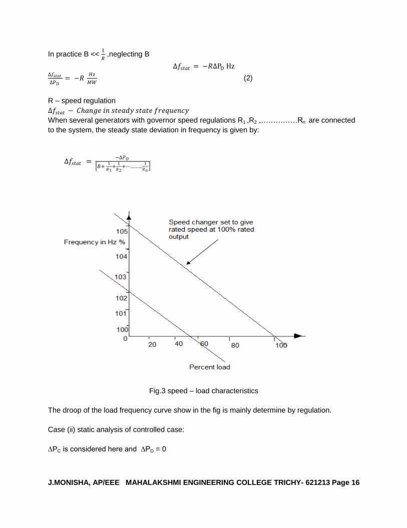
In practice B << 1
𝑅 ,neglecting B
∆𝑓𝑠𝑡𝑎𝑡 = −𝑅∆PD Hz ∆𝑓𝑠𝑡𝑎𝑡
∆PD = −𝑅
𝐻𝑧
𝑀𝑊 (2)
R – speed regulation
∆𝑓𝑠𝑡𝑎𝑡 − 𝐶𝑎𝑛𝑔𝑒 𝑖𝑛 𝑠𝑡𝑒𝑎𝑑𝑦 𝑠𝑡𝑎𝑡𝑒 𝑓𝑟𝑒𝑞𝑢𝑒𝑛𝑐𝑦
When several generators with governor speed regulations R1 ,R2 ,……………Rn are connected
to the system, the steady state deviation in frequency is given by:
∆𝑓𝑠𝑡𝑎𝑡 = −∆𝑃𝐷
𝐵+ 1
𝑅1+
1
𝑅2+⋯………
1
𝑅𝑛
Fig.3 speed – load characteristics
The droop of the load frequency curve show in the fig is mainly determine by regulation.
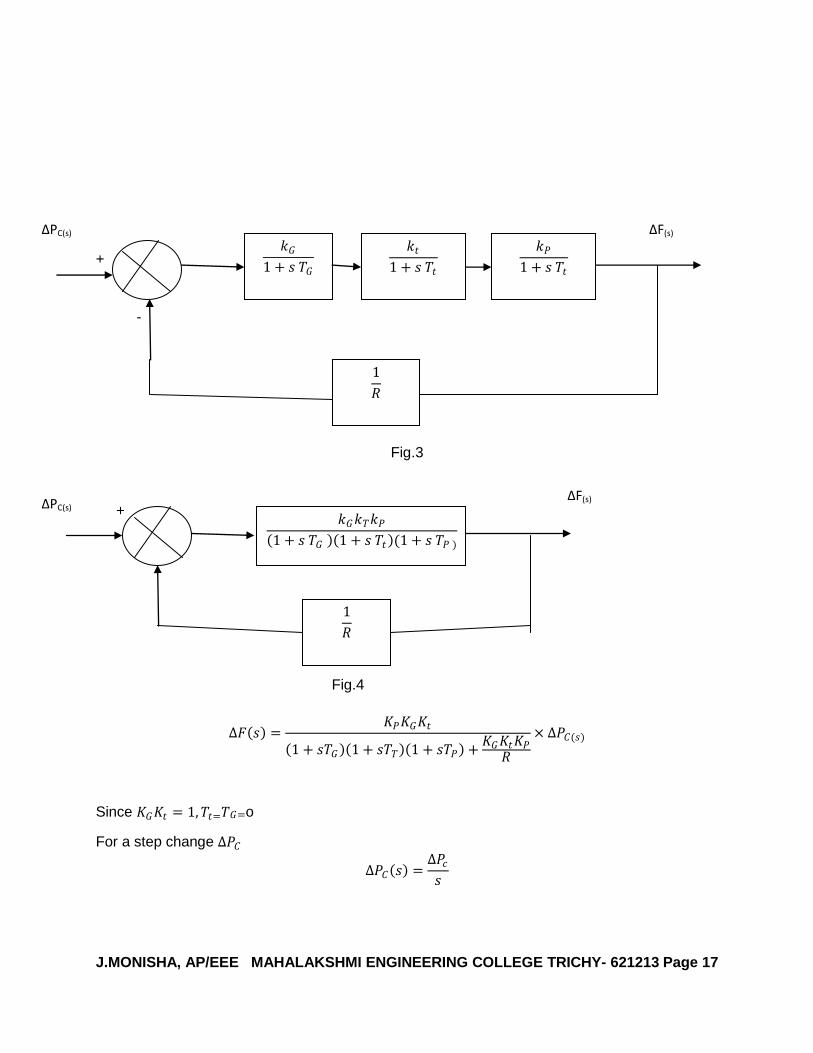
Case (ii) static analysis of controlled case:
∆PC is considered here and ∆PD = 0
J.MONISHA, AP/EEE MAHALAKSHMI ENGINEERING COLLEGE TRICHY- 621213 Page 17
+
-
Fig.3
+
Fig.4
∆𝐹 𝑠 =𝐾𝑃𝐾𝐺𝐾𝑡
1 + 𝑠𝑇𝐺 1 + 𝑠𝑇𝑇 1 + 𝑠𝑇𝑃 +𝐾𝐺𝐾𝑡𝐾𝑃
𝑅
× ∆𝑃𝐶(𝑠)
Since 𝐾𝐺𝐾𝑡 = 1, 𝑇𝑡=𝑇𝐺=o
For a step change ∆𝑃𝐶
∆𝑃𝐶 𝑠 =∆𝑃𝑐𝑠
𝑘𝐺
1 + 𝑠 𝑇𝐺
𝑘𝑡
1 + 𝑠 𝑇𝑡
𝑘𝑃
1 + 𝑠 𝑇𝑡
1
𝑅
∆PC(s) ∆F(s)
1
𝑅
𝑘𝐺𝑘𝑇𝑘𝑃
1 + 𝑠 𝑇𝐺 1 + 𝑠 𝑇𝑡 (1 + 𝑠 𝑇𝑃 )
∆PC(s) ∆F(s)
J.MONISHA, AP/EEE MAHALAKSHMI ENGINEERING COLLEGE TRICHY- 621213 Page 18
∆𝐹 𝑠 =𝐾𝑃
1 + 𝑠𝑇𝐺 1 + 𝑠𝑇𝑇 1 + 𝑠𝑇𝑃 +𝐾𝐺𝐾𝑡𝐾𝑃
𝑅
×∆𝑃𝐶
𝑠
Applying final value theorem
∆fstat = 𝐿𝑡 s. ∆F(s)
s 0
∆fstat=𝐾𝑃
1+𝐾𝑃𝑅
∆𝑃𝐶
∆fstat=
𝟏
𝑩
𝟏+𝟏
𝑩𝑹
∆𝑷𝑪=
𝟏
𝑩+𝟏𝑹
∆𝑷𝒄
∆fstat =1
𝐵 +1𝑅
𝐻𝑍/𝑀𝑊
Case(III):if the controlling force ∆𝑷𝒄is applied to the speed changer and the load demand
changes by ∆𝑷𝒄the static frequency change is obtained by superposition theorem
∆fstat =𝐾𝑃
1 +𝐾𝑃𝑅
(∆𝑃𝐶 − ∆𝑃𝐷)
for the above equation
for ∆fstat=0 we get ∆𝑃𝐶 = ∆𝑃𝐷
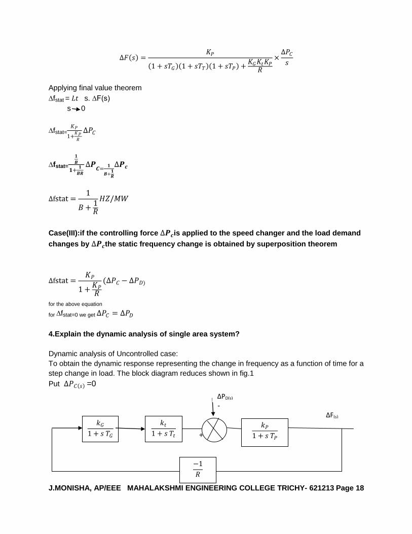
4.Explain the dynamic analysis of single area system?
Dynamic analysis of Uncontrolled case:
To obtain the dynamic response representing the change in frequency as a function of time for a
step change in load. The block diagram reduces shown in fig.1
Put ∆𝑃𝐶 𝑠 =0
-
+
𝑘𝐺
1 + 𝑠 𝑇𝐺
𝑘𝑡
1 + 𝑠 𝑇𝑡
𝑘𝑃
1 + 𝑠 𝑇𝑃
−1
𝑅
∆PD(s)
∆F(s)

J.MONISHA, AP/EEE MAHALAKSHMI ENGINEERING COLLEGE TRICHY- 621213 Page 19
Fig.1
∆F(s) =
𝑘𝑃1+ 𝑠𝑇𝑃
1+ 𝑘𝑃𝑘𝐺𝑘𝑡
𝑅 1+ 𝑠𝑇𝐺 1+ 𝑠𝑇𝑡 (1+ 𝑠𝑇𝑃 −∆PD s (1)
We can simplify the analysis by making the following assumptions.
1.The action of speed governor and turbine is instantaneously compared with rest of the power
system.
2.The time constant of the power system TP = 20sec
time constant of governor TG= 0.4 sec
time constant Tt = 0.5sec
Considering Tt = TG = 0 𝑘𝐺𝑘𝑡 = 1
The block diagram reduces as shown in fig.2
-
-
Fig.2
∆F(s) = 𝑘𝑃
1+ 𝑠𝑇𝑃 + 𝑘𝑃𝑅
−∆PD s
∆PD s =
∆PD s
s
∆F(s) = 𝑘𝑃
𝑇𝑃 𝑠+ 1
𝑇𝑃+
𝑘𝑃𝑅𝑇𝑃
−∆PD s
s
On applying partial fraction method it can be reduced to,
∆F(s) = −∆PD
𝑇𝑃𝑘𝑝
𝑅𝑇𝑃
𝑅+ 𝑘𝑃 ×
1
𝑠−
1
𝑠+ 𝑅+ 𝑘𝑃𝑅𝑇𝑃
Applying inverse laplace transform,we get,
∆f(t) = −∆𝑃𝐷𝑘𝑃 𝑅
𝑅+𝑘𝑃 1 − 𝑒
𝑅+ 𝑘𝑃
𝑘𝑃 𝑡
∆f(t) = −𝑀 𝑘𝑃 𝑅
𝑅+𝑘𝑃 1 − 𝑒
𝑅+ 𝑘𝑃
𝑘𝑃 𝑡
(2)
𝑘𝑃
1 + 𝑠 𝑇𝑃
1 1
𝑅
∆F(s)
∆PD(s)
J.MONISHA, AP/EEE MAHALAKSHMI ENGINEERING COLLEGE TRICHY- 621213 Page 20
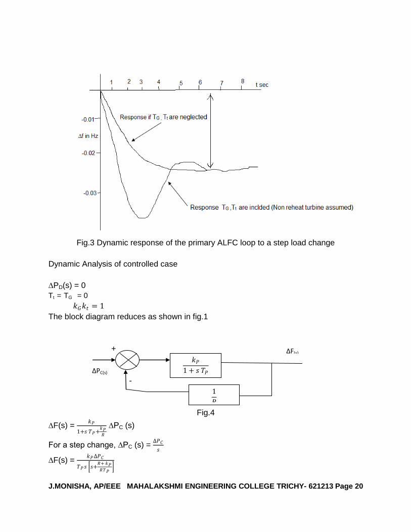
Fig.3 Dynamic response of the primary ALFC loop to a step load change
Dynamic Analysis of controlled case
∆PD(s) = 0
Tt = TG = 0 𝑘𝐺𝑘𝑡 = 1
The block diagram reduces as shown in fig.1
+
-
Fig.4
∆F(s) = 𝑘𝑃
1+𝑠 𝑇𝑃+𝑘𝑃𝑅
∆PC (s)
For a step change, ∆PC (s) = ∆𝑃𝐶
𝑠
∆F(s) = 𝑘𝑃∆𝑃𝐶
𝑇𝑃𝑠 𝑠+𝑅+ 𝑘𝑃𝑅𝑇𝑃
𝑘𝑃
1 + 𝑠 𝑇𝑃
1
𝑅
∆F(s)
∆PC(s)

J.MONISHA, AP/EEE MAHALAKSHMI ENGINEERING COLLEGE TRICHY- 621213 Page 21
∆f(t) = ∆𝑃𝐶𝑘𝑃𝑅
𝑅+ 𝑘𝑃 1 − 𝑒
− 𝑅+ 𝑘𝑃𝑅𝑇𝑃
𝑡
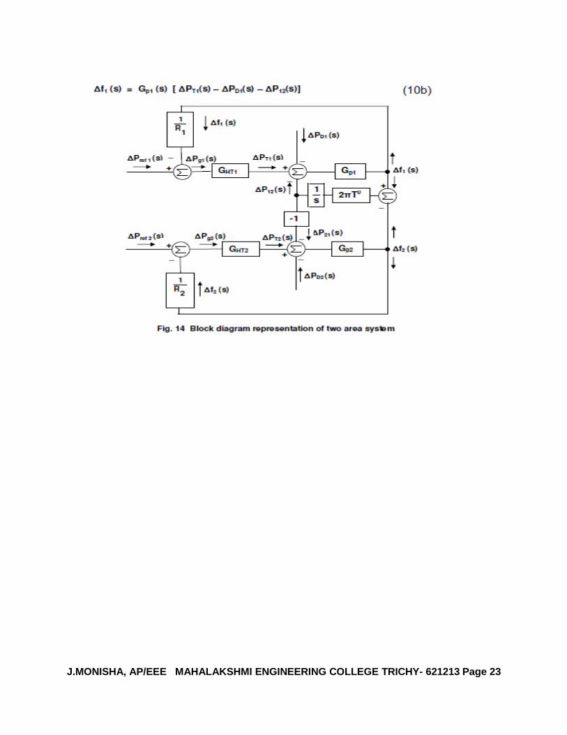
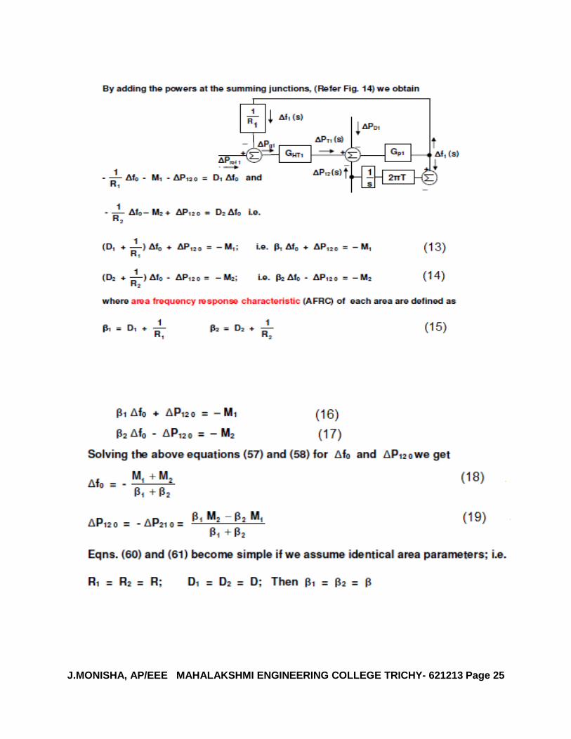
5.Explain the two area system of static and dynamic controlled system? [AUC
NOV/DEC 2012 APR/MAY 2011 NOV/DEC 2009] [AUC MAY/JUN 2012]

J.MONISHA, AP/EEE MAHALAKSHMI ENGINEERING COLLEGE TRICHY- 621213 Page 22
J.MONISHA, AP/EEE MAHALAKSHMI ENGINEERING COLLEGE TRICHY- 621213 Page 23

J.MONISHA, AP/EEE MAHALAKSHMI ENGINEERING COLLEGE TRICHY- 621213 Page 24
J.MONISHA, AP/EEE MAHALAKSHMI ENGINEERING COLLEGE TRICHY- 621213 Page 25

J.MONISHA, AP/EEE MAHALAKSHMI ENGINEERING COLLEGE TRICHY- 621213 Page 26

J.MONISHA, AP/EEE MAHALAKSHMI ENGINEERING COLLEGE TRICHY- 621213 Page 27
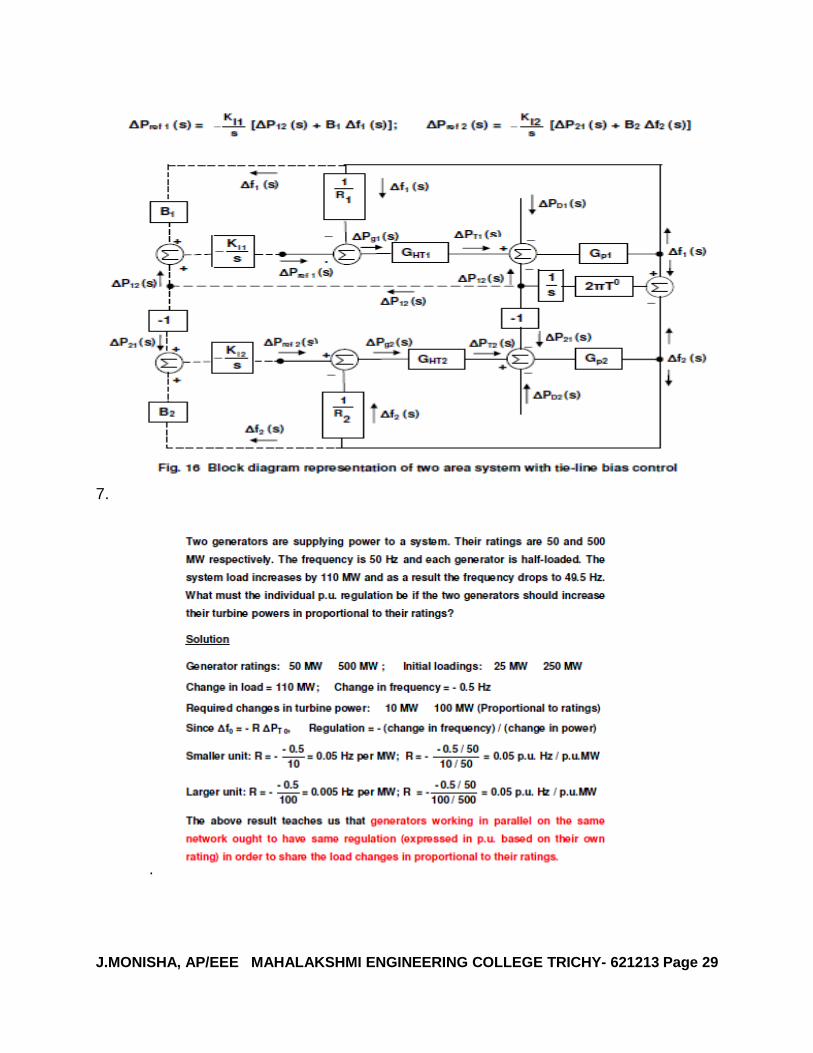
6. Explain the tie base control for to area system? [AUC MAY/JUNE 2009]

J.MONISHA, AP/EEE MAHALAKSHMI ENGINEERING COLLEGE TRICHY- 621213 Page 28
J.MONISHA, AP/EEE MAHALAKSHMI ENGINEERING COLLEGE TRICHY- 621213 Page 29
7.
.
Related Documents