Otto-Hahn-Straße 20 Postfach 10 03 27 Telefon +49(0)2181 – 75665-0 Fax +49(0)2181 – 64492 01/06/2003 D-41515 Grevenbroich D-41487 Grevenbroich E-Mail: [email protected] ITA with Aluminium- Indication rail and switch ITA with mA-ouput signal and digital display with volume linearization ITA with steam casing ITA with Armaflex- Isolation (refrigerant) Inspection/certificate ITA, material PVDF 1. Material certificate EN 10204 2.1 2. Material certificate EN 10204 2.1 3. Material certificate EN 10204 3.1 B 4. Test according to NACE 5. Pressuretest certificate 6. Pressuretest according to AD-Merkblatte by German TÜV 7. Construction and pressure test as per TRD by the TÜV 8. Dye penetration test DIN 54152 9. X-Ry test in accordance with DIN 54111, part 1 10. PMI-Check 11. PTB/Ex certificate 12. General approval of construction inspection in according with §19 water resources law about flammable liquids-VbF 13. Water level controller component-check as per VdTÜV/WR91-352 14. Germanischer Lloyd 15. Certification of passivation 16. Weight certificate Magnetically controlled fluid level indicator, type ITA

Welcome message from author
This document is posted to help you gain knowledge. Please leave a comment to let me know what you think about it! Share it to your friends and learn new things together.
Transcript

Otto-Hahn-Straße 20 Postfach 10 03 27 Telefon +49(0)2181 – 75665-0 Fax +49(0)2181 – 64492 01/06/2003 D-41515 Grevenbroich D-41487 Grevenbroich E-Mail: [email protected]
ITA with Aluminium- Indication rail
and switch
ITA with mA-ouput signal and digital display with
volume linearization
ITA with steam casing
ITA with Armaflex- Isolation (refrigerant)
Inspection/certificate ITA, material PVDF
1. Material certificate EN 10204 2.1 2. Material certificate EN 10204 2.1 3. Material certificate EN 10204 3.1 B 4. Test according to NACE 5. Pressuretest certificate 6. Pressuretest according to AD-Merkblatte by
German TÜV 7. Construction and pressure test as per TRD by
the TÜV 8. Dye penetration test DIN 54152 9. X-Ry test in accordance with DIN 54111, part 1 10. PMI-Check 11. PTB/Ex certificate 12. General approval of construction inspection in
according with §19 water resources law about flammable liquids-VbF
13. Water level controller component-check as per VdTÜV/WR91-352
14. Germanischer Lloyd 15. Certification of passivation 16. Weight certificate
Magnetically controlled fluid level indicator, type ITA

M E S S - U N D R E G E L I N S T R U M E N T E
elektronische M eß-und Regelinstrumente
- 1 -
Table of contents
ISO 9001 Certificate page 2
Functioning and general informationMagnetic Levelgauge type ITA page 3 Level measurement tasks page 3 Advantages page 4 Floats page 4 Switches and alarm contacts page 4 Indication rail page 5 Materials page 5 Special versions page 5 Additional equipment page 5 Acceptance tests and certificates page 5
LevelgaugesITA-3, ITA-3.0 page 6 ITA-3 Cryo, ITA-3.0 Cryo page 7 ITA-34, ITA-64 page 8 ITA-3.5, ITA-3.5.0 page 9 ITA-3.8 page 10 ITA-4, ITA-4.0 page 11 ITA-4.1, ITA-4.1.0 page 12 ITA-5, ITA-5.0 page 13 ITA-5.1, ITA-5.1.0 page 14 ITA-5.5 page 15 ITA-6, ITA-6.0 page 16 ITA-6 Cryo, ITA-6.0 Cryo page 17 ITA-6.8 page 18 ITA-7, ITA-7.0 page 19 ITA-8.1, ITA-8.2, ITA-8.3 page 20 ITA-9.1, ITA-9.2, ITA-9.3 page 21 ITA-10, ITA-10.0 page 22 ITA-11, ITA-11.0 page 23 ITA-12, ITA-12.0 page 24 ITA-12.D, ITA-12.0.D page 25 ITA-13, ITA-13.0 page 26
EquipmentITA-3 Cryo, ITA-3.0 Cryo page 27 Armaflex isolation page 28 Technical data switches page 29-32 Contact NJ-Ex page 33 Indication rails page 34 Digital indication with volume linnearization page 35 Level-source page 36 Reed-contact page 37 Transmitter page 38 ITA-T1S page 39-42 ITA-T1R page 43
Date : 29.05.02


Functioning and general information
- 4 -
Advantages
Switches / alarm contacts
Floats
No risk of glass breakage as a result of the separation of the measurement and indicator areas. The float principle means that changes of the density in the medium have very little influence on the indication accuracy.
Magnetic level indicators can be equipped with an arbitrary number of switch contacts. In contrast to electric float switches, switch contacts may be installed at any position of the stand pipe. Wherever additional float chambers are for float switches, magnetically controlled level indicators offer a considerable price benefit.
Electrical level measurement transducers which use the displacement principle must be recalibrated each time the fluid density has changed. The price of a magnetically controlled level indicator with integral electrical measurement transducer is considerably lower than level measurement transducers. The reed chain with an R/I measurement transducer can be changed without interrupting the operation. The measurement chamber is hermetically sealed - there is no contact between the fluid chamber and the reedchain.
The construction of the float requires a great amount of technical know-leage. The float with its special magnet can rotate freely in the float chamber. The Intra construction avoids a guide wire and other devices. The float materials are stainless steel, 1.4571, 1.4435 (316L) or titanium (PVC, PP, PVDF in case of the plastics level gages). Floats without gas-prestressing are used from a minimum density of 0,35 kg/dm^3. The maximum process pressure for sealed floats is 250 bar; at higher pressures the floats must be relieved from pressure (not to be used for condensing media).
The switches / alarm contacts are secured with pipe clips, and can be adjusted to any desired height. The connection is using a 3-core cable or casing terminals. The changeover contact can be used as opener or closer. The switches are also available as explosion-proof version.

Functioning and general information
- 5 -
Indication rail
Materials
The ITA level gauges can be delivered with indication rails made from 2 different materials. Macrolon indication rails are resistable to breakage. The max. per-missible media-temperature is 120°C, with 20°C ambient temperature and natural convection as test conditions. The rails are resistable to UV-radiation and aggressive atmosphere and are sealed against dust by two seal-caps. Aluminium indication rails can be delivered as a one part rail up to a length of 6m. The sight cover material depends on the temperature, up to 150°C the material is macrolon and up to 400°C it is glass. The surface of the indication rail can be coated with Säkaphen if required, the standardized surface is brown-anodized.
The gauge chamber and the floats are made of stainless steel (1,4571), 254SMO (1.4529), 1.4435 (316L), titanium, hasteloy, PVC, PP, PVDF, and PTFE. Other material on request.
Special versions
Additional equipment
Inspection/certificate
1. Transmitter, output signal 0-20 mA or 4-20 mA 2. Steam jacket, e.g. for viscous media 3. Float chamber with armaflex insulation, for temperatures below zero 4. Scale made of gravoply (white plastics) or aluminium red-anodized 5. Two-parts versions without interruption of the indication, for
measuring lengths > 6m 6. Works report DIN 50049 7. Level indicator in GL-design (Germanischer Lloyd,Bureau
Veriatas/Det Norsk Veritas, Lloyda Register) 8. Usage as an overfilling guard for tanks for storing inflammable and
non-flammable waterpolluting liquids 9. ITA cryogenic version for refrigerants 10. ITA with lining made of PTFE 11. ITA with inside-coating made of E-CTFE (halar)
1. Antifreezing heating belt for use in the open air 2. Vent/drain valves, screw or flange connection 3. Measurement scale, divisions to client' specification 4. Armaflex insulation 5. Protective hose, additional protection of the indicator against dust,
dirt and moisture 6. Plastics-indicator with armouring
1. Material certificate EN 10204 2.1 2. Material certificate EN 10204 2.2 3. Material certificate EN 10204 3.1 A/B/C 4. Test according to NACE 5. Pressuretest certificate 6. Pressuretest according to AD-Merkblatt by the German TÜV 7. Construction and pressure test as per TRD by the TÜV 8. Dye penetration test DIN 54 152 9. X-ray test in accordance with DIN 54 111, part1 10. PMI-check 11. PTB/Ex certificate 12. General approval of construction inspection in accordance with §19
water resources law -WHG- and §12 law about flammable liquids -VbF
13. Water level conroller component-check as per VdTÜV/WR91-352 14. Germanischer Lloyd 15. Certificate of passivation 16. Weight certificate 17. PED 97/23/EG

Titel ITA3_e
Pricelist Unit Revision: 5
Type Date:10.04.2002
Rating Page 6
max. 5000 mm (one part)
> 5000 mm 2- or multiparts
60,3 x 2 mm welded,
60,3 x 2 mm seamless,
2“ sch10
Buttweld construction with t-pieces
to specify:
Flanged DN15-40 (½"-1½" 150#
RF)
Welding or threaded stud
Flanged DN50 o. 2" 150# RF
Plugged R½"
(see. Code F)
316 Ti
Hasteloy C4 (2.4610),
Inconel 625 (2.4856)
Inconel 825 (2.4858)
Titanium (3.7035)
other materials also avaibleas pipe material,
(type ITA-3.0): Carbon steel
316Ti
Titanium, Titanium/E-CTFE coated
Op. temperature : -50 bis +400 °C
Op. pressure : max. 16 bar
0,7374 kg/dm³ *
min.: 0,3371 kg/dm3 (depending on float type)
CS
SS
PTFE up to 100 °C
Klingersil up to 400°C
Makrolon up to 120 °C
Aluminium up to 400 °C
316SS up to 400 °C
Cylindrical, sealed type
Length:
270 mm
130 mm
150 mm
210 mm
330 mm
430 mm
530 mm
630 mm
A=240 *
B=130
C=40
Principle : Communicating tubes with magnetic float
Mounting position : vertical
Measuring range :
Pipe size :
Process connections :
Vent/drain connections :
Pipe material :
Flange material :
Float material :
Density :
Bolts, Nuts :
Gaskets :
Indicationrail :
Float types :
Mag. Levelgauge
ITA-3 and ITA-3.0
PN16
Base equipment for mag. levelgauge type ITA-3 and ITA-3.0
Base equipment printed bold!
* For densitys < 0,7374 kg/dm³ enlarge the scale A
Dimensions :
Intra-Automation GmbH, Otto-Hahn-Str. 20, D-41515 Grevenbroich, +49-(0)2181/75665-0, Fax: +49-(0)2181-64492, Mail: [email protected]

Titel ITA3CRYO_e
Pricelist Unit Revision: 5
Type Date:10.04.2002
Rating Page 7
max. 5000 mm (one part)
> 5000 mm 2_ or multiparts
60,3 x 2 mm welded (type Cryo and
CR60)
64 x 2 mm welded (type CR64)
to specify:
Flanged DN15-50 (½"-2"150# RF)
Welding or threaded stud
Plugged R½"
(see Code F)
316Ti
as pipe material,
(type ITA-3.0 Cryo): Carbon steel
CS
SS
PTFE
Klingersil
Aluminium
316SS
Cylindrical, sealed type
Cryo 50,8 x 270mm
CR64 50,8 x 530mm
CR60 45 x 530 mm
Base equipment printed bold!
Mag. Levelgauge
ITA-3 Cryo and ITA-3.0 Cryo
Cryogenic application
Base equipment for mag. levelgauge type ITA-3 Cryo and ITA-3.0 Cryo
Indicationrail :
Float types :
Bolts, Nuts :
Gaskets :
Op. pressure : max. 16 bar
min. density : 0,389 kg/dm3 (depending on float)
Float material : Titanium
Op. temperature : -50 bis +100 °C
Pipe material :
Flange material :
Process connections :
Vent/drain connections :
Measuring range :
Pipe size :
Principle : Communicating tubes with magnetic float
Mounting position : vertical
Intra-Automation GmbH, Otto-Hahn-Str. 20,D-41515 Grevenbroich, Tel.: +49-(0)2181-75665-0, Fax: +49-(0)2181/64492, Mail: [email protected]

Titel ITA34_e
Pricelist Unit Revision: 5
VK00-29 Type Date: 15.05.2002
Rating Page 8
max. 5000 mm (one part)
> 5000 mm 2- or multiparts
to specify:
Flanged DN15-25 (½"-1")
Flanged DN32-50 o.(1½"-2")
Flanged DN15-25
Flanged DN32-50
see Code F
Pipe material : 316Ti, wetted parts PTFE
1,0 kg/dm3 *
min.: 0,85 kg/dm³
(depending on float)
CS
SS
Aluminium
316SS
Cylindrical, sealed type
Length: 270 mm
(Special floats on request)
Principle : Communicating tubes with magnetic float
Mounting position : vertical
Measuring range :
Pipe size : 69 x 2,0 mm welded
Process connections :
Vent/drain connections :
Flange material : as pipe material
Float material : PVDF
-50 bis +120 °C
Op. pressure : max. 16 bar not to use for vacuum service
:
Bolts, Nuts :
Op. temperature :
Base equipment printed bold!
Mag. Levelgauge
ITA-34 and ITA-64
PN16-PN40
Base equipment for mag. levelgauge type ITA-34 and ITA-64
Indicationrail :
Float types :
Density
Intra-Automation GmbH, Otto-Hahn-Str. 20, D-41515 Grevenbroich, Tel.: +49-(0)2181/75665-0, Fax: +49-(0)2181/64492, Mail: [email protected]

Titel ITA35_e
Pricelist Unit Revision: 5
Type Date:10.04.2002
Rating Page 9
max. 3100 mm (one part/
length over all max. 3500 mm)
> 3500 mm 2- or multiparts
60,3 x 2 mm welded,
60,3 x 2 mm seamless,
2“ Sch10
buttweld construction with t-pieces
to specify:
Flanged DN20-40 (¾"-1½" 150# RF)
Flanged DN50 o. 2" 150# RF
as pipe material
1,0 kg/dm³ *
min.: 0,55 kg/dm3
(depending on float)
CS
SS
PTFE up to 100 °C
Klingertop-chem-200 up to 260°C
Makrolon up to 120 °C
Aluminium up to 400 °C
316SS up to 400°C
Cylindrical, sealed type
Length:
270 mm
150 mm
330 mm
430 mm
530 mm
A=240 *
B=130
Principle : Communicating tubes with magnetic float
Mounting position : vertical
Measuring range :
Pipe size :
Process connections :
Vent/drain connections : (see. Code F)
Pipe material : 316Ti ,wetted parts E-CTFE
Flange material :
Float material : Titanium/E-CTFE coated
Op. temperature : -50 bis +160 °C
Op. pressure : max. 16 bar
Density :
Bolts, Nuts :
Gaskets :
Indicationrail :
Float types :
Mag. Levelgauge
ITA-3.5 and ITA-3.5.0
PN16
Base equipment for mag. levelgauge type ITA-3.5 and ITA-3.5.0
Base equipment printed bold!
* For densitys < 1,0 kg/dm³ enlarge the scale A
Dimensions :
Intra-Automation GmbH, Otto-Hahn-Str. 20, D-41515 Grevenbroich, Tel.: +49-(0)2181-75665-0, Fax: +49-(0)2181-64492, Mail: [email protected]

Titel ITA38_e
Pricelist Unit Revision: 0
Type Date:14.05.2002
Rating Page 10
max. 2800 mm (one part/
length over all max. 2900 mm)
> 2900 mm 2- or multiparts
69 x 2 mm welded,
69 x 2 mm seamless,
to specify:
Flanged DN20-50 (¾"-2" 150# RF)
Flanged DN50 o. 2" 150# RF
as pipe material
1,0 kg/dm³ *
min.: 0,55 kg/dm3
(depending on float)
CS
SS
PTFE up to 100 °C
Klingertop-chem-200 up to 260°C
Makrolon up to 120 °C
Aluminium up to 400 °C
316SS up to 400°C
Cylindrical, sealed type
Length:
270 mm
150 mm
330 mm
430 mm
530 mm
A=240 *
B=130
C=40
Principle : Communicating tubes with magnetic float
Mounting position : vertical
Measuring range :
Pipe size :
Process connections :
Vent/drain connections : (see. Code F)
Pipe material : 316Ti ,wetted parts E-CTFE
Flange material :
Float material : Titanium/E-CTFE coated
Op. temperature : -50 bis +160 °C
Op. pressure : max. 16 bar / vacuum resistance
Density :
Bolts, Nuts :
Gaskets :
Indicationrail :
Float types :
Mag. Levelgauge
ITA-3.8
PN16
Base equipment for mag. levelgauge type ITA-3.8
Base equipment printed bold!
* For densitys < 1,0 kg/dm³ enlarge the scale A
Dimensions :
Intra-Automation GmbH, Otto-Hahn-Str. 20, D-41515 Grevenbroich, Tel.: +49-(0)2181-75665-0, Fax: +49-(0)2181-64492, Mail: [email protected]

Titel ITA4_e
Pricelist Unit Revision: 3
VK00-29 Type Date:10.04.2002
Rating Page 11
to specify:
Flanged DN50 PN16 or 2"150#
(see Code F)
Plugged R½"
(see. Code F)
316Ti
Hasteloy C4 (2.4610),
Inconel 625 (2.4856)
Inconel 825 (2.4858)
Titanium (3.7035)
other materials also avaibleas pipe material,
(type ITA-4.0: Carbon steel)
316Ti
Titanium, Titanium/E-CTFE coated
CS
SS
PTFE up to 100 °C
Klingersil up to 400°C
Makrolon up to 120 °C
Aluminium up to 400 °C
316SS up to 400°C
Float types : Cylindrical, sealed type
Base equipment printed bold!
Mag. Levelgauge
ITA-4 and ITA-4.0
PN16
Base equipment for mag. levelgauge type ITA-4 and ITA-4.0
Gaskets :
Indicationrail :
min. density : 0,559 kg/dm3 (depending on meas. range)
Bolts, Nuts :
-50 bis +400 °C
Op. pressure : max. 16 bar
Float material :
Op. temperature :
Pipe material :
Flange material :
Process connections :
Vent connections :
Measuring range : max. 2750 mm
Pipe size : 60,3 x 2 mm welded,
Principle : Communicating tubes with magnetic float
Mounting position : top of tank
Intra-Automation GmbH, Otto-Hahn-Str. 20, D-41515 Grevenbroich, Tel.: +49-(0)2181-75665-0, Fax: +49-(0)2181/64492, [email protected]

Titel ITA41_e
Pricelist Unit Revision: 5
VK00-29 Type Date:10.04.2002
Rating Page 12
to specify:
Flanged DN100 PN16 (4" 150# RF)
316Ti
Hasteloy C4 (2.4610),
Inconel 625 (2.4856)
Inconel 825 (2.4858)
Titanium (3.7035)
other materials also avaibleas pipe material,
(type ITA-4.1.0: Carbon steel)
CS
SS
PTFE up to 100 °C
Klingersil up to 400°C
Makrolon up to 120 °C
Aluminium up to 400 °C
316SS up to 400°C
Float types : Cylindrical, sealed type
Base equipment printed bold!
Indicationrail :
Mag. Levelgauge
ITA-4.1 and ITA-4.1.0
PN16
Base equipment for mag. levelgauge type ITA-4.1 and ITA-4.1.0
Bolts, Nuts :
Gaskets :
Op. pressure : atmospheric
min. density : 0,277 kg/dm3 (depending on meas. range))
Float material : Titanium
Op. temperature : -50 bis +400 °C
Plugged R½"
Pipe material :
Flange material :
Process connections :
Vent connections :
Measuring range : max. 2750 mm
Pipe size : 88,9 x 2 mm welded,
Principle : Communicating tubes with magnetic float
Mounting position : top of tank
Intra-Automation GmbH, Otto-Hahn-Str. 20, D-41515 Grevenbroich, Tel.: +49-(0)2181/75665-0, Fax: +49-(0)2181-64492, Mail: [email protected]

Titel ITA5_e
Pricelist Unit Revision: 4
VK00-29 Type Date:10.04.2002
Rating Page 13
max. 5000 mm (one part)
> 5000 mm 2- or multiparts
60,3 x 2 mm welded
2“ Sch10
60,3 x 2- 8,7 mm seaml. (depending on pressure rating)
to specify:
R½" threaded (up to PN40)
Welding or threaded stud
Flanged DN15-DN50 (½"-2")
316Ti
Hasteloy C4 (2.4610),
Inconel 625 (2.4856)
Inconel 825 (2.4858)
Titanium (3.7035)
other materials also avaible
as pipe material,
(type ITA-5.0: Carbon steel)
316Ti
Titanium, Titanium/E-CTFE coated
0,75 kg/dm³ *
min.: 0,35 kg/dm3
(depending on float)
CS
SS
PTFE up to 100 °C
Klingersil up to 400°C
Camprofile or spiral wound
Makrolon up to 120 °C
Aluminium up to 400 °C
316SS up to 400°C
A=240 *
B=130 (up to PN64)
Base equipment printed bold!
* For Densitys < 0,75 kg/dm³ enlarge the scale A
Mag. Levelgauge
ITA-5 and ITA-5.0
PN16-PN320
Base equipment for mag. levelgauge type ITA-5 and ITA-5.0
Float types : Cylindrical, sealed type or vented type (depending on pressure rating)
Dimensions :
Gaskets :
Indicationrail :
Density :
Bolts, Nuts :
Op. temperature : -50 bis +400 °C
Op. pressure : max. 16 bar up to 320 bar
Flange material :
Float material :
Process connection :
Pipe material :
Measuring range :
Pipe size :
Principle : Communicating tubes with magnetic float
Mounting position : vertical
Intra-Automation GmbH, Otto-Hahn-Str. 20, D-41515 Grevenbroich, Tel.: +49-(0)2181/75665-0,Fax: +49-(0)2181/64492, Mail: [email protected]

Titel ITA51_e
Pricelist Unit Revision: 4
VK00-29 Type Date:10.04.2002
Rating Page 14
max. 5000 mm (one part)
> 5000 mm 2- or multiparts
60,3 x 2 mm welded,
60,3 x 2 mm seamless,
2“ Sch 10
to specify:
R½" threaded
Welding or threaded stud
316Ti
Hasteloy C4 (2.4610),
Inconel 625 (2.4856)
Inconel 825 (2.4858)
Titanium (3.7035)
other materials also avaibleas pipe material,
(type ITA-5.1.0: Carbon steel)
316Ti
Titanium, Titanium/E-CTFE coated
0,639 kg/dm³ *
min.: 0,3987 kg/dm3
(depending on float)
CS
SS
PTFE up to 100 °C
Klingersil up to 400°C
Makrolon up to 120 °C
Aluminium up to 400 °C
316SS up to 400°C
Principle : Communicating tubes with magnetic float
Mounting position : vertical
Measuring range :
Pipe size :
Process connections :
Pipe material :
Flange material :
Float material :
Op. temperature : -50 bis +400 °C
Op. pressure : max. 40 bar
Density :
Bolts, Nuts :
: A=240 *
Gaskets :
Indicationrail :
Base equipment printed bold!
* For densitys < 0,75 kg/dm³ enlarge the scale A
Mag. Levelgauge
ITA-5.1 and ITA-5.1.0
PN16
Base equipment for mag. levelgauge type ITA-5.1 and ITA-5.1.0
Float types : Cylindrical, sealed type
Dimensoins
Intra-Automation GmbH, Otto-Hahn-Str. 20, D-41515 Grevenbroich, Tel.: +49-(0)2181/75665-0, Fax: +49-(0)2181-64492, Mail: [email protected]

Titel ITA55_e
Pricelist Unit Revision: 2
VK00-29 Type Date:10.04.2002
Rating Page 15
max. 3100 mm (one part/
hole length 3500 mm)
> 3500 mm 2- or multiparts
316Ti
as pipe material,
CS
SS
PTFE up to 100 °C
Makrolon up to 100 °C
Aluminium up to 400 °C
316SS up to 400°C
A=240
B=130
Base equipment printed bold!
Cylindrical, sealed type
Dimensions :
Mag. Levelgauge
ITA-5.5
PN16
Base equipment for mag. levelgauge type ITA-5.5
Indicationrail :
Float types :
Bolts, Nuts :
Gaskets :
Op. pressure : max. 16 bar
min. density : 0,55 kg/dm3 (depending on float)
Float material : Titanium/Halar- coated
Op. temperature : -50 bis +150 °C
Pipe material :
Flange material :
Pipe size : 60,3 x 2 mm welded
Process connection : Flanged DN20-DN50 (¾"-2")
wetted parts Halar (E-CTFE)
Klingertop-chem-200 up to 260°C
Principle : Communicating tubes with magnetic float
Mounting position : vertical
Measuring range :
Intra-Automation GmbH, Otto-Hahn-Str. 20, D-41515 Grevenbroich, Tel.: +49-(0)2181-75665-0, Fax: +49-(0)2181-64492, Mail: [email protected]

Titel ITA6_e
Pricelist Unit Revision: 6
VK00-29 Type Date:10.04.2002
Rating Page 16
max. 5000 mm (one part)
> 5000 mm 2- or multiparts
60,3 x 2 mm welded,
60,3 x 2 mm seamless,
2“ Sch10
buttweld construction with t-pieces
to specify:
Flanged DN15-25 (½"-1" 300# RF)
Welding or threaded stud
Flanged DN50 o. 2" 300# RF
Plugged R½"
(see code F)
316Ti
Hasteloy C4 (2.4610),
Inconel 625 (2.4856)
Inconel 825 (2.4858)
Titanium (3.7035)
other materials also avaibleas pipe material,
(type ITA-6.0: Carbon steel)
316Ti
Titanium, Titanium/E-CTFE coated
Op. temperature : -50 bis +400 °C
Op. pressure : max. 40 bar
0,639 kg/dm³ * up to 20 bar process pressuremin.: 0,3987 kg/dm3 up to 40 bar process pressure(depending on float type)
CS
SS
PTFE up to 100 °C
Klingersil up to 400°C
Makrolon up to 120 °C
Aluminium up to 400 °C
316SS up to 400°C
Cylindrical, sealed type
Length: 270 mm
130 mm
150 mm
210 mm
330 mm
430 mm
530 mm
630 mm
A=240 *
B=130
C=40
Base equipment printed bold!
* For densitys < 0,75 kg/dm³ enlarge the scale A
Dimensions :
Mag. Levelgauge
ITA-6 and ITA-6.0
PN40
Base equipment for mag. levelgauge type ITA-6 and ITA-6.0
Indicationrail :
Float types :
Bolts, Nuts :
Gaskets :
Float material :
Density :
Pipe material :
Flange material :
Process connections :
Vent/drain connections :
Measuring range :
Pipe size :
Principle : Communicating tubes with magnetic float
Mounting position : vertical
Intra-Automation GmbH, Otto-Hahn-Str. 20, D-41515 Grevenbroich, Tel.: +49-(0)2181-75665-0, Fax: +49-(0)2181-64492, Mail: [email protected]

Titel ITA6CRYO_e
Pricelist Unit Revision: 5
VK00-29 Type Date:10.04.2002
Rating Page 17
max. 5000 mm (one part)
> 5000 mm 2- or multiparts
60,3 x 2 mm welded type Cryo and CR60
64 x 2 mm welded type CR64
to specify:
Flanged DN15-50 (½"-2"300# RF)
Welding or threaded stud
Plugged R½"
(see Code F)
316Ti
other material on request
as pipe material,
(type ITA-6.0: Carbon steel)
CS
SS
PTFE
Klingersil
Aluminium
316SS
Cylindrical, sealed type
Cryo 50,8 x 270 mm
CR64 50,8 x 530 mm
CR60 45 x 530 mm
Principle : Communicating tubes with magnetic float
Mounting position : vertical
Measuring range :
Pipe size :
Process connections :
Vent/drain connections :
Pipe material :
Flange material :
Float material : Titanium
Op. temperature : -50 bis +100 °C
max. 40 bar
min. density : 0,4566 kg/dm3 ((depending on float)
:
Gaskets :
Op. pressure :
Base equipment printed bold!
Mag. Levelgauge
ITA-6 Cryo and ITA-6.0 Cryo
Cryogenic application
Base equipment for mag. levelgauge type ITA-6 Cryo and ITA-6.0 Cyro
Indicationrail :
Float types :
Bolts, Nuts
Intra-Automation GmbH, Otto-Hahn-Str. 20, D- 41515 Grevenbroich, Tel.: +49-(0)2181-75665-0, Fax: +49-(0)2181-64492, Mail: [email protected]
Titel ITA68_e
Pricelist Unit Revision: 0
Type Date:14.05.2002
Rating Page 18
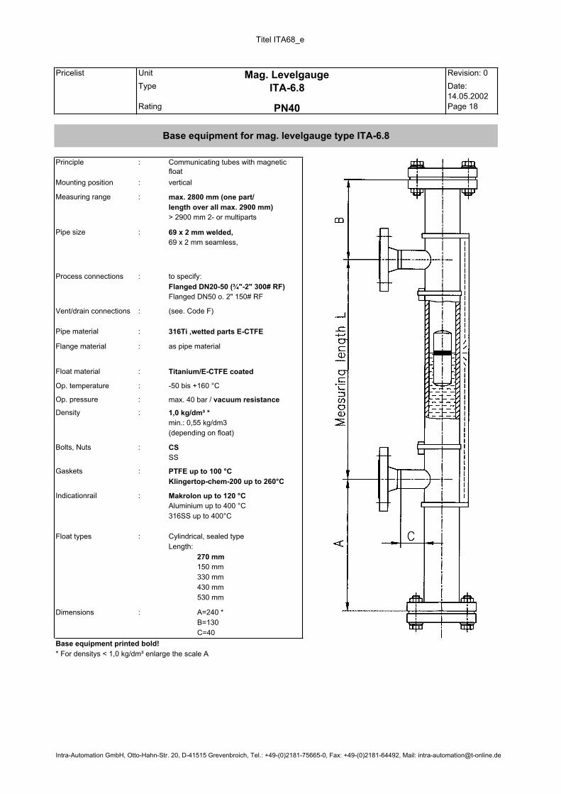
max. 2800 mm (one part/
length over all max. 2900 mm)
> 2900 mm 2- or multiparts
69 x 2 mm welded,
69 x 2 mm seamless,
to specify:
Flanged DN20-50 (¾"-2" 300# RF)
Flanged DN50 o. 2" 150# RF
as pipe material
1,0 kg/dm³ *
min.: 0,55 kg/dm3
(depending on float)
CS
SS
PTFE up to 100 °C
Klingertop-chem-200 up to 260°C
Makrolon up to 120 °C
Aluminium up to 400 °C
316SS up to 400°C
Cylindrical, sealed type
Length:
270 mm
150 mm
330 mm
430 mm
530 mm
A=240 *
B=130
C=40
Base equipment printed bold!
* For densitys < 1,0 kg/dm³ enlarge the scale A
Dimensions :
Mag. Levelgauge
ITA-6.8
PN40
Base equipment for mag. levelgauge type ITA-6.8
Indicationrail :
Float types :
Bolts, Nuts :
Gaskets :
Op. pressure : max. 40 bar / vacuum resistance
Density :
Titanium/E-CTFE coated
Op. temperature : -50 bis +160 °C
Flange material :
Float material :
(see. Code F)
Pipe material : 316Ti ,wetted parts E-CTFE
Process connections :
Vent/drain connections :
Measuring range :
Pipe size :
Principle : Communicating tubes with magnetic float
Mounting position : vertical
Intra-Automation GmbH, Otto-Hahn-Str. 20, D-41515 Grevenbroich, Tel.: +49-(0)2181-75665-0, Fax: +49-(0)2181-64492, Mail: [email protected]

Titel ITA7_e
Pricelist Unit Revision: 5
VK00-29 Type Date:15.04.2002
Rating Page 19
max. 5000 mm (one part)
> 5000 mm 2- or multiparts
60,3 x 2,9 mm seamless,
butt weld construction with t-pieces
to specify:
Flanged DN15-25 (½"-1" 300#)
Welding or threaded stud
Flanged DN32-50 (1¼ " or 2" 300#)
plugged ½" NPT
(see Code F)
316Ti
Hasteloy C4 (2.4610),
Inconel 625 (2.4856)
Inconel 825 (2.4858)
Titanium (3.7035)
other materials also avaibleas pipe material,
(type ITA-7.0: Carbon steel)
0,682 kg/dm³ *
min.: 0,4243 kg/dm3
(depending on float)
CS
SS
Spiral wound, 316Ti
Cam profile, 316Ti
Makrolon up to 120 °C
Aluminium up to 400 °C
316SS up to 400°C
Cylindrical, sealed type
Length:
270 mm
330 mm
530 mm
630 mm
A=240 *
B=130
C=40
Principle : Communicating tubes with magnetic float
Mounting position : vertical
Measuring range :
Pipe size :
Process connections :
Vent/drainconnections
:
Pipe material :
Flange material :
Float material : Titanium, Titanium/E-CTFE coated
Op. temperature : -50 bis +400 °C
Op. pressure : max. 64 bar
Density :
Bolts, Nuts :
Gaskets :
Indicationrail :
Float types :
Mag. Levelgauge
ITA-7 and ITA-7.0
PN64
Base equipment for mag. levelgauge type ITA-7 and ITA-7.0
Base equipment printed bold!
* For densitys < 0,6 kg/dm³ enlarge the scale A
Dimensions :
Intra-Automation GmbH, Otto-Hahn-Str. 20, D-41515 Grevenbroich, Tel.: +49-(0)2181-75665-0, Fax: +49-(0)2181-64492, Mail: [email protected]

Titel ITA8_e
Pricelist Unit Revision: 5
VK00-29 Type Date:15.04.2002
Rating Page 20
max. 5000 mm (one part)
> 5000 mm 2- or multiparts
ITA-8.1: 63 x 4,7 mm,
ITA-8.2: 63 x 3,6 mm,
ITA-8.3: 63 x 3 mm
Plug R½"
(see Code F)
ITA-8.1: PVC,
ITA-8.2: PP,
ITA-8.3: PVDF
ITA-8.1: PVC,
ITA-8.2: PP,
ITA-8.3: PVDF
PVC : -30 bis +60 °C
PP : -10 bis +80 °C
PVDF: -40 bis +120 °C
ITA-8.1: 0,75 kg/dm³ *
ITA-8.2: 0,65 kg/dm³ *
ITA-8.3: 0,85 kg/dm³ *
(depending on float)
Gaskets : Viton
Aluminium
316SS
Cylindrical, sealed type
Length: 255 mm
135 mm
A=240 *
B=130
D=110
* For densitys < 0,75 kg/dm³ for ITA-8.1, < 0,65 kg/dm³ for ITA-8.2 and < 0,85 kg/dm³ for ITA-8.3 enlarge the scale A
Base equipment for mag. levelgauge type ITA-8.1, ITA-8.2 and ITA-8.3
Mag. Levelgauge
ITA-8.1, ITA-8.2 and ITA-8.3
PN6 (Plastics)
Base equipment printed bold!
Float types :
Dimensions :
Bolts, Nuts : SS
Indicationrail :
Op. pressure : max. 6 bar
min. density :
as pipe material
Float material :
Op. temperature :
Pipe material :
Flange material :
Process connections : Flanged DN15-50 (½"-2")
Vent/drain connections :
Measuring range :
Pipe size :
Principle : Communicating tubes with magnetic float
Mounting position : vertical
Intra-Automation GmbH, Otto-Hahn-Str. 20, D-41515 Grevenbroich, Tel.: +49-(0)2181-75665-0, Fax: +49-(0)2181-64492, [email protected]

Titel ITA9_e
Pricelist Unit Revision: 4
VK00-29 Type Date:15.04.2002
Rating Page 21
ITA-9.1: 63 x 4,7 mm,
ITA-9.2: 63 x 3,6 mm,
ITA-9.3: 63 x 3 mm
Flanged DN15-50 (½" - 2“)
Flanged DN50-DN150 (2"-4")
Flanged DN32 PN6
(see Code F)
ITA-9.1: PVC,
ITA-9.2: PP,
ITA-9.3: PVDF
ITA-9.1: PVC,
ITA-9.2: PP,
ITA-9.3: PVDF
PVC : -30 bis +60 °C
PP : -10 bis +80 °C
PVDF: -40 bis +120 °C
Gaskets : Viton
Aluminium
316SS
Cylindrical, sealed type
Length: 250 mm
(special sizes available)
Base equipment printed bold!
Float types :
Mag. Levelgauge
ITA-9.1, ITA-9.2 and ITA-9.3
PN6 (Plastics)
Base equipment for mag. levelgauge type ITA-9.1, ITA-9.2 and ITA-9.3
Bolts, Nuts : SS
Indicationrail :
Op. pressure : atm.
min. density : 0,7 kg/dm3 (depending on float and material)
as pipe material
Float material :
Op. temperature :
Pipe material :
Flange material :
Process connections :
Vent connections :
Measuring range : max. 2500 mm
Pipe size :
Principle : Communicating tubes with magnetic float
Mounting position : top of tank
Intra-Automation GmbH, Otto-Hahn-Str. 20, D-41515 Grevenbroich, Tel.: +49-(0)2181-75665-0, Fax: +49-(0)2181-64492, Mail: [email protected]

Titel ITA10_e
Pricelist Unit Revision: 6
VK00-29 Type Date:15.04.2002
Rating Page 22
max. 5000 mm (one part)
> 5000 mm 2- or multiparts
60,3 x 3,2 mm seamless,
butt weld construction with t-pieces
to specify:
Flanged DN15-25(½"-1" 600#)
Welding or threaded stud
Flanged DN32-50 (1¼" or 2" 600#)
Vent/Drain plug ½" NPT
(see Code F)
316Ti
Hasteloy C4 (2.4610),
Inconel 625 (2.4856)
Inconel 825 (2.4858)
Titanium (3.7035)
other materials also avaibleas pipe material,
(type ITA-10.0: Carbon steel)
0,8394 kg/dm³ *
min.: 0,5698 kg/dm3
(depending on float)
CS
SS
Spiral wound, 316Ti
Cam profile, 316Ti
Makrolon up to 120 °C
Aluminium up to 400 °C
316SS up to 400°C
Cylindrical, sealed type
Length:
270 mm
330 mm
430 mm
530 mm
630 mm
A=240 *
B=170
C=70
Principle : Communicating tubes with magnetic float
Mounting position : vertical
Measuring range :
Pipe size :
Process connections :
Vent/drainconnections
:
Pipe material :
Flange material :
Float material : Titanium, Titanium/E-CTFE coated
Op. temperature : -50 bis +400 °C
Op. pressure : max. 100 bar
Density :
Bolts, Nuts :
Gaskets :
Indicationrail :
Float types :
Mag. Levelgauge
ITA-10 and ITA-10.0
PN100
Base equipment for mag. levelgauge type ITA-10 and ITA-10.0
Base equipment printed bold!
* For densitys < 0,8394 kg/dm³ enlarge the scale A
Dimensions :
Intra-Automation GmbH, Otto-Hahn-Str. 20, D- 41515 Grevenbroich, Tel.: +49-(0)2181-75665-0, Fax: +49-(0)2181-64492, Mail: [email protected]

Titel ITA11_e
Pricelist Unit Revision: 5
VK00-29 Type Date:15.04.2002
Rating Page 23
max. 5000 mm (one part)
> 5000 mm 2- or multiparts
60,3 x 3,91 mm seamless
60,3 x 3,6 mm seamless
butt weld construction with t-pieces
to specify:
Flanged DN15-25 (½"-1" 1500#)
Welding or threaded stud
Flanged DN32-50 (1¼" o. 2" 1500#)
Plug ½" NPT
(see Code F)
316Ti
Hasteloy C4 (2.4610),
Inconel 625 (2.4856)
Inconel 825 (2.4858)
Titanium (3.7035)
other materials also avaible
as pipe material,
(type ITA-11.0: Carbon steel)
Titanium
316Ti
0,7736 kg/dm³ vented type
0,8478 kg/dm3 sealed type
CS
SS
Spiral wound, 316SS
Cam profile, 3165SS
Makrolon up to 120 °C
Aluminium up to 400 °C
316SS up to 400°C
Titanium Length: 270 mm
Length: 270 mm
210 mm
330 mm
430 mm
530 mm
A=240 *
B=170
C=70
* For densitys < 0,7 kg/dm³ enlarge the scale A
Base equipment for mag. levelgauge type ITA-11 and ITA-11.0
Mag. Levelgauge
ITA-11 and ITA-11.0
PN160
Base equipment printed bold!
Float types :
Dimensions :
Gaskets :
Indicationrail :
Density :
Bolts, Nuts :
-50 bis +400 °C
Op. pressure : max. 160 bar
Float material :
Op. temperature :
Pipe material :
Flange material :
Process connections :
Vent/drainconnections
:
Measuring range :
Pipe size :
Principle : Communicating tubes with magnetic float
Mounting position : vertical
Measu
ring le
ngth
L
Intra-Automation GmbH, Otto-Hahn-Str. 20, D-41515 Grevenbroich, Tel: +49-(0)2181-75665-0, Fax: +49-(0)2181-64492, Mail: [email protected]

Titel ITA12_e
Pricelist Unit Revision: 6
VK00-29 Type Date:15.04.2002
Rating Page 24
max. 5000 mm (one part)
> 5000 mm 2- or multiparts
60,3 x 5,54 mm seamless,
butt weld construction with t-pieces
to specify:
Flanged DN15-25 (½"-1" 1500#)
Welding or threaded stud
Flanged DN32-50 (1¼" o. 2" 1500#)
Plug ½" NPT
(see Code F)
316Ti
Hasteloy C4 (2.4610),
Inconel 625 (2.4856)
Inconel 825 (2.4858)
Titanium (3.7035)
other materials also avaible
as pipe material,
(type ITA-12.0: Carbon steel)
Titanium
0,57kg/dm3 vented float
0,828 kg/dm³ sealed float
CS
SS
Spiral wound, 316Ti
Cam profile, 316Ti
Makrolon up to 120 °C
Aluminium up to 400 °C
316SS up to 400°C
Length: 270 mm
Cylindrical, sealed type (Titanium) Length: 270 mm
430mm
A=240 *
B=170
C=100
Base equipment printed bold!
* For densitys < 0,7 kg/dm³ enlarge the scale A
Mag. Levelgauge
ITA-12 and ITA-12.0
PN250
Base equipment for mag. levelgauge type ITA-12 and ITA-12.0
Float types :
Dimensions :
Gaskets :
Indicationrail :
Density :
Bolts, Nuts :
-50 bis +400 °C
Op. pressure : max. 250 bar
Float material :
Op. temperature :
Pipe material :
Flange material :
Process connections :
Vent/drain connections :
Measuring range :
Pipe size :
Principle : Communicating tubes with magnetic float
Mounting position : vertical
Intra-Automation GmbH, Otto-Hahn-Str. 20, D- 41515 Grevenbroich, Tel.: +49-(0)2181-75665-0, Fax: +49-(0)2181-64492, Mail: [email protected]

Titel ITA12D_e
Pricelist Unit Revision: 0
VK00-29 Type Date:16.04.2002
Rating Page 25
max. 5000 mm (one part)
> 5000 mm 2- or multiparts
60,3 x 8,7 mm seamless,
butt weld construction with t-pices
to specify:
Flanged DN15-25 (½"-1" 1500#)
Welding or threaded stud
Flanged DN32-50 (1¼" o. 2" 1500#)
Plug ½" NPT
(see Code F)
as pipe material,
(type ITA-12.0.D: Carbon steel)
Float material : Titanium
Float design : sealed
Diameter 38mm
CS
SS
Spiral wound, 316SS
Cam profile, 316SS
Aluminium up to 400 °C
316SS up to 400°C
Cylindrical, sealed type, (Titanium)
Length: 430 mm
A=400 *
B=170
C=100
Base equipment printed bold!
Mag. Levelgauge
ITA-12.D and ITA-12.0.D
PN200
Base equipment for mag. levelgauge type ITA-12.D and ITA-12.0.D
Float types :
Dimensions :
Gaskets :
Indicationrail :
Density : 0,71 kg/dm3
Bolts, Nuts :
Op. temperature : +350 °C
Op. pressure : max. 200 bar
Pipe material : 316Ti
Flange material :
Processconnections
:
Vent/drainconnections
:
Measuring range :
Pipe size :
Principle : Communicating tubes with magnetic float
Mounting position : vertical
Intra-Automation GmbH, Otto-Hahn-Str. 20, D-41515 Grevenbroich, Tel.: 02181/75665-0, Fax: 02181/64492, Mail: [email protected]

Titel ITA13_e
Pricelist Unit Revision: 4
VK00-29 Type Date:16.04.2002
Rating Page 26
max. 5000 mm (one part)
> 5000 mm 2- or multiparts
60,3 x 8,7 mm seamless,
butt weld construction with t-pieces
to specify:
Flanged DN15-25 (½"-1" 2500#)
Welding or threaded stud
Flanged DN32-50 (1¼" o. 2" 2500#)
Vent/Drain plug ½" NPT
(see Code F)
316Ti
Hasteloy C4 (2.4610),
Inconel 625 (2.4856)
Inconel 825 (2.4858)
Titanium (3.7035)
other materials also avaible
as pipe material,
(type ITA-13.0: Carbon steel)
0,71 kg/dm3 sealed float (max.
pressure 250bar)
CS
SS
Spiral wound, 316SS
Cam profile, 316SS
Makrolon up to 120 °C
Aluminium up to 400 °C
316SS up to 400°C
330 mm430 mm
A=240 *
B=170
C=100
Principle : Communicating tubes with magnetic float
Mounting position : vertical
Measuring range :
Pipe size :
Process connections :
Vent/drain connections :
Pipe material :
Flange material :
Float material : Titanium
Op. temperature : -50 bis +400 °C
Op. pressure : max. 320 bar
min. density : 0,72 kg/dm3 * vented float
Bolts, Nuts :
Gaskets :
Indicationrail :
Float types :
Mag. Levelgauge
ITA-13 and ITA-13.0
PN320
Base equipment for mag. levelgauge type ITA-13 and ITA-13.0
Base equipment printed bold!
* For densitys < 0,72 kg/dm³ enlarge the scale A
Cylindrical,vented type, (Titanium))
Length: 270 mm
Dimensions :
Intra-Automation GmbH, Otto-Hahn-Str. 20, D-41515 Grevenbroich, Tel.: +49-(0)2181/75665-0, Fax: +49-(0)2181/64492, Mail: [email protected]

Information for use type ITA-3 and ITA-6 in Cryo-design
If Armaflex is used for insulation (t=9mm) the material for the indication rail will be aluminium. As standard for the level gauge in cryo-design we use a float chamber 60,3 2mm with a float from titanium ( 50,8x240mm length) down to a liquid density of 0,6kg/dm3).For temperatures below 40°C the Armaflex insulation is double ply, the upper layer only up to the
indication rail. The customer should also insulate the process-flanges. For vaporizing media (for example ammonia) we recom-mend you to use floats with 4 distance sleeves. (In this case the floats are smaller than standard floats). This construction prevents catapulting the float upwards (this would cause switch failures) if gas evolution appears. The distance sleeves (see drawing) hold the float in the center of the float chamber, so the gas can move away wihout shaking the float. For temperatures down to 20°C we are using a float chamber 60,3 2mm and a titanium float45 400mm, for temperatures below 20°C we are using a float chamber 64 2mm and a titanium float 50,8 500mm. In every case we use flanges DN50 as drain connections (weld neck and blind flange with groove and tongue). When the diameter of the float chamber is 64 2mm it is necessary to modify the weld neck flange. On request by the customer we make use of a small hole (throttling part) to transmit the liquid level to the float chamber. It stabilize the float movement (damping).
240
(500)
9
D
distance sleeve
throttling part dependence on the temperature: ø4mm for T –20°C
ø2mm for T < –20°C
- 27 -

AArrmmaafflleexx iissoollaattiioonn
-- 2288 --

HHeeaattiissoollaattiioonn
CCeerraammiiccaall ffiibbrree--tteexxttiilleess wwiitthhoouutt aassbbeessttooss ppaarrttss..
LLiimmiittiinngg tteemmppeeaarruutteerree:: 11226600°°CCCCoonnttiinniioouuss tteemmppeerraattuurree:: 660000°°CC ((wwiitthh ffiibbeerr ggllaassss rreeiinnffoorrcceedd))
BBaannddss ttiigghhtt sseellvveeddggee wwiitthh ggllaassss aammpplliiffiieedd,, ssiizzee 33mmmm..
TTeecchhnniiccaall ddaattaass::
CCoommppoossiittiioonn ooff tthhee cceerraammiiccaall ffiibbrree iinn %% :: ccaa.. 4455%% AAll22OO33 ++ ccaa..5544%% SSiiOO22 ++ ccaa.. 11%%FFee22OO33,, TTiiOO22,, MMggOO,, NNaa22OO ++ KK22OO,, BB22OO33
PPoorrttiioonn oorrggaanniicc ssuubbssttaannccee :: ccaa.. 1122%% -- 1177%%SSaattuurraanntt :: wwiitthhoouuttCCoommbbuussttiibbllee :: nnooDDeennssiittyy [[gg//ccccmm]] :: 99,,66LLiimmiittiinngg tteemmppeerraattuurree :: mmaaxx.. 11226600°°CC -- ddeeppeennddeenntt uuppoonn aapppplliiccaattiioonnCCoonnttiinniioouuss tteemmppeerraattuurree :: 660000°°CC,, iiff ffiibbeerrggllaassss rreeiinnffoorrcceeddDDeeggrreeee ooff mmooiissttuurree :: 11%%TThheerrmmaall ccoonndduuccttiivviittyy :: CCrruuddee ffiibbrree:: ccaa..00,,0044 KKccaall//mmhh aatt 440000°°CC
mmiiddddllee tteemmppeerraattuurreeccaa.. 00,,0088 KKccaall//mmhh aatt 660000°°CCmmiiddddllee tteemmppeerraattuurree
AAnnnneeaalliinngg lloossss :: nnoo aannnneeaalliinngg lloossss,, bbeeccaauussee tthheerree iiss nnoo ccoonnssttiittuuttiioonnaall wwaatteerrCCoommpprreessssiibbiilliittyy :: oonn wwoovveenn tteexxttiillee aanndd bbaannddss:: ccaa.. 55%% aatt 1133kkgg//qqmm
ccaa.. 1100%% aatt 2288 kkgg//qqmmCCoonnssoolliiddaattiioonn :: tthhrroouugghh :: 990000°°CC 00%%
11000000°°CC 11,,2255%%11220000°°CC 33,,77%%
RReessiissttaannccee aaggaaiinnsstt :: 11.. OOiill,, sstteeaamm,, wwaatteerr aanndd aallll cchheemmiiccaall wwiitthh eexxcceeppttiioonn ooffhhyyddrroofflluuoorriicc aacciidd,, pphhoosspphhoorroouuss aacciidd aanndd ddeetteerrmmiinneeddaallkkaalliinnee ssoolluuttiioonn..
22.. LLiiqquuiidd mmeettaall.. IItt ddoonn´́tt aaffffeecctteedd aanndd wweetttteedd bbyy ffuusseeddAAlluummiinniiuumm aanndd ZZiinncc..
33.. IInnffeerriioorr ccoonntteenntt uuppoonn ccoommppoouunndd ooff cchhlloorriinnee,, tthheerree iiss lliittttlleerriisskk ooff ffrraaccttuurree bbyy cchhlloorriinnee ccoorrrroossiioonn..
44.. GGoooodd rreessiissttaannccee aaggaaiinnsstt sscchhoocckkeedd ooccccuurrrreennccee hheeaatt aannddvviibbrraattiioonn..
55.. GGoooodd aaccoouussttiiccaall aanndd eelleeccttrriiccaall iissoollaattiioonn..
-- 2299 --

- 30 -
Technical data switches
1. General table
Switch 1690 16090 Ex LMS-A LMS-A-EExd MS09K MS10 EExd
Case synthetic synthetic Al Si 12 Al Si 12 synthetic Aluminium Contact
function
bistable change-over
contact
bistable change-over
contact
bistable change-over contact **
bistable change-over contact
break- or make-contact, change-over
contact
break- or make-contact, change-over
contact Dimension 20x15x80 20x15x80 65x65x40 Drm 138x80 110x75x50 120x120x110
Breaking on 230VAC 230VAC 12 - 250 VAC 220VAC 250VAC 250VAC rupturing 0,8A 0,4A 1,5A 1,5A 10A 10A capacity 60VA 30VA 80VA 80VA --- ---
Protective
system
IP65 IP65 IP65 DIN40050
IP65 DIN40050
IP65 DIN40050
IP65 DIN40050
Option IP67 DIN40050
IP67 DIN40050
--- --- --- ---
Switch-
hysteresis
15mm 15mm 8 - 12mm 8 - 12mm --- ---
Medium-
temperature
max. 130°C max. 130°C max. 250°C * max. 250°C * max. 100°C max. 200°C
EEx-
protection
--- EEx d II CT6 --- EEx d II CT6 --- EEx dII CT6
Connection --- --- PG7,5 4 connection (¾“ NPT)
PG11 ¾“ NPT
Electric connection with 3-channel plug and earth. For all Switchs valid the international standard EN 60529. * Typ LMS-AH with heat-protection-execution through a max. temperature of 400°C. ** available with gold-contact.
2. NI Ex NU-Switch
Inherent safety EEx-switch, on inquiry with define error message.
Contact- supply voltage: 8V DC transmiter max. temperature: 60°C
cabel connection at the case:
PG11
Section supply voltage: 220V +15% (45 - 60Hz) switch power consumption: ca. 1,5V appliance open-cicuit voltage: 8V DC
admit charge: 4A / 250V / 250VA admit temperature: -20°C bis +60°C
3. Switchschema
Type Schema
1680
bistable change-over contact
1690
bistable change-over contact
LMS-A
bistable change-over contact
LMS-AH
bistable change-over contact

Technical data switches
Switch LMS-A Scwitch LMS-AH
Switch 1690 / 1690 Ex Switch MS 09 K
Switch MS 10 EExd Switch LMS-A-Eexd
- 31 -

- 32 -
Technical data switches
Switch NI Ex NJ

Contact NJ-EX
The Contact NJ-EX is an inductive contact NJ 1.5-6.5 N, kontex system protective system (Ex) i G5.
Function
Actuation is provided by the magnet installed in the float. The follow magnet system of the contact maker moves the switching disc, which serves for releasing the contact between two small inductances of the slotted initiator and thereby varies the attenduation of the resonant circuit.
Technical Data
electric connection : 8V DC temp./ambient temp. : -25°C up to +60°C cable connections : PG 11 (other screwed cable connections on the switching housing upon request)
Switch Relay
WE 77/Ex 1 : for 1 inductive contact (Ex) i G5 WE 77/Ex 2 : for 2 inductive contacts (Ex) i G5
- 33 -

IInnddiiccaattiioonn rraaiillss
AArrmmaafflleexx--iissoollaattiioonn aanndd hheeaattiinngg ttaappee IITTAA IInnddiiccaattiioonn rraaiill wwiitthh ssccaallee ffoorr IITTAA
IInnddiiccaattiioonn rraaiill,, mmaatteerriiaall MMaakkrroolloonn IInnddiiccaattiioonn rraaiill,, mmaatteerriiaall AAlluummiinniiuumm IInnddiiccaattiioonn rraaiill,, mmaatteerriiaall 331166SSSS
11.. SSeeaalliinngg ccaapp 11.. UU--pprrooffiillee 11.. UU--pprrooffiillee22.. IInnddiiccaattiioonn llaammiinnaa wwiitthh mmaaggnneett 22.. IInnddiiccaattiioonn llaammiinnaa wwiitthh mmaaggnneett 22.. IInnddiiccaattiioonn llaammiinnaa wwiitthh mmaaggnneett33.. RReeccttaanngguullaarr pprrooffiillee 33.. TTrraannssppaarreenntt ccoovveerriinngg 33.. TTrraannssppaarreenntt ccoovveerriinngg44.. UU-- pprrooffiillee
-- 3344 --

ITA - magnetically controlled level indicator with analog signal (4-20mA) - and
digital display
Electrical level measurement transductors which use the diplacemant principle must be recalibrated each time the fluid density is changed.
The price of a magnetically controlled level indicator with integral electrical measurement transducer is considerably lower than level measurement transducers.
The reed chain with an R/I measurment transducer can be changed without interupting operation. The measurement chamber is hermetically sealed - there is no contact between the fluid chamber and the reed chain.
With the microprocessor-controlled level indicator unit type 420, the level can be displayed direct in any arbitrary physical measurement unit. The indicator has a curve calculator with which nonlinear tank contents can be displayed direct in cubic meters.
- 35 -

- 36 -
Niveau-source
Measuring principle: The resistance chain with the reed contacts are build in a pipe made of material 316SS. This so called ‘Reed Chain’ is mounted on the float chamber with jubilee clips. According to movement of the float, the float magnet closes one reed contact which produces a voltage (or resistance) proportional to the height of the liquid in the tank. You get an near-analogous output signal, with a resolution of about 10 mm. The resistance chain receives its power supply from the transmitter. The 4-20mA transmitter output signal can be given to an indicator or can be used to drive alarm contacts. In the case of an error the output signal becomes higher than 22mA.
Connection: As a standard the reed chain is supplied with a transmitter that is installed inside the housing-head, 2-wire connection to the transmitter, is only required.

- 37 -
Standart reed chain
Max. medium temperature: 150°C Protection pipe: 14mm Material 316Ti Encosure: IP65
Clamp standart
Reed chain for higher temperature
Max. medium temperature: 400°C Protection pipe: 14mm Material 316Ti Enclusre: IP65 Heat protection: 50 x 4mm
Clamp special Will be needed by armaflex isolation and secondary mounting off a reed chain.

- 38 -
Available housings Available transmitters
Standard-transmitter-housing
material aluminium Pg16 entry
Type :PR S333B EExia IIC T5/T6
output: 4 – 20 mA
power supply 2 – 36 VDC
lineary: ± 0,1 %
Eexd transmitter housing
material aluminium epoxy coated
½ » NPT cable entry
Type: TMT 182
EExia IIC T4
output: 4 – 20 mA (Hart-Protocol)
power supply 13 – 30 VDC
lineary: 400 -area ± 0,04 4000 -area ± 0,5
input:: 5-400 / 50-4000
Stainless steel transmitter housing
material 316 Ti M20-1,5 entry

Technical Information ITA-T1S
39
Technical Information ITA-T1S
Special features
Introduction
Operating
Simple and rugged design Reliable performance in liquids with densities of
0.5 kg/dm³ Short mounting depth 300 mm (11.81”), therefore suitable for small vessels Indicating length up to 3000 mm (118”) Resistant to pressures of 40 bar (580 psig) and temperatures of 130 °C (266 °F) Housing of cast aluminium or stainless steel in IP 65 equivalent to Nema 4 and Nema 4x enclosure Wide variety of material combinations Various plastic coatings available for all wetted parts 4 to 20 mA or Hart protocol 4 to 20 mA output via the signal conditioner
INTRA-Automation doesn´t limit you with the standard designs cataloged here. Our experienced engineering staff, with extensive research and development capa-bilities, will customize liquid level indicators to meet your specific requirements. Modifications regarding the variety of mountings, exotic materials and float configurations provides compatibly for most liquid media, various tank temperatures and pressures, as well as liquids with a broad range of specific gravities.
The ITA-T1S Liquid Level Transmitters, vertically mounted in the tank and cable-connected (3-wire) to a remote receiver, operates on the float principle. A float guided on a non-magnetic tube follows the level of the liquid surface, thereby actuating the reed switches located inside the tube by means of a built-in magnet system. The reed switches shunt over parts of a resistor string. The magnet system operates the reed switches accor-ding to the position of the float and thus causes the ohmic resistance of the resistor string to change as a function of liquid level. A current 4 to 20 mA is then obtained as an output signal together with the M501, T2Fr124 or TMD832 signal conditioner. The float travel distance can be limited by stops fitted to the guide tube.
fig.1: ITA-T1S with EExd-housing and
tank mounting flange
fig.2: diagrammatic view of reed switches

Technical Information ITA-T1S
40
Monitoring
Interface
measuring
Combined with DigiFlow 520 these transmitters form a complete liquid level monitoring system. Used as a separate system within a process control system, INTRA transmitters can interface with programmable controllers and other industrial microprocessors.
Very often dissimilar liquids resides in a tank. Most tank gauging methods are limited in these cases, and only indicate the level of the uppermost surface. But, with using INTRA-Automation ITA-T1S level sensing elements, you can easily monitor the interface between liquids. By adjusting the specific gravity of the magnet float, INTRA can adapt the transmitter to monitor the interface of a broad range of media. This principle applies to oil and water, slurries, acids, bilge and other dissimilar liquids. In conjunction with DigiFlow 520 tank level, ITA-T1S will help assure that only the “correct” liquid is taken from a tank, or introduced into a process system.
fig.3: DigiFlow 520
fig.4: tank monitoring
Technical Data Level transmitter Overall length Measuring accuracy Ambient temperature
Aluminium housing Stainless steel housing
Tank product Temperature Min. density Max. allowable operating pressure
Protection category DIN 40 050/ IEC 144) Terminals Cable entry
Aluminium housing Stainless steel housing
Current output Connection
Screw connection to ISO Screw connection to ANSI/ASME Flanges to DIN Flanges to ANSI
Materials Housing
Standard Special Explosion-proofed
Flange
Thread Guide tube
Float
ITA-T1S
0.3 m to 6 m (0.98 ft. to 1969 ft.) 5, 10 or 20 mm ( 0.2”, 0.39” or 0.79”)
-40°C to +60°C (-40°F to +140°F) -40°C to +60°C (-40°F to +140°F)
-10°C to +100°C (+14°F to +212°F) 0.5 kg/dm³ (31.21 lbs/ft.³) 40 bar (580 psig) IP 65 (NEMA 4,4x) max. 1.5 mm² (AWG 14 cable cross sect.)
PG 16 (optional M20x1.5) PG 13.5 (optional M20x1.5) other entries on request 4 to 20 mA (optional 4 to 20 mA Hart)
R ½” ½” NPT-M DN 50, DN 100; PN 16 and PN 40 2”, 4”; Class 150 lbs/RF and 300 lbs/RF other connections on request
cast aluminium (option: with epoxy finish) stainless steel cast aluminium with epoxy finish carbon steel, stainless steel (optional Halar coated), PP, PVC, PVDF stainless steel carbon steel, stainless steel (optional Halar coated), PP, PVC, PVDF see “float type”

Technical Information ITA-T1S
41
Float type
Transmitter
Type 1)
Shape Dimensions
in mm (inches)
Material Min.
density
kg/dm³
(lbs/ft³)
Max. operating
pressure
in bar (psig)
at 20°C (68°F)
Max. product
temperature
in °C (°F)
A Spherical 52
(2.05) 1.4571 316Ti
0.7 (43.70)
40(580)
-40 to +100 (-40 to +266)
B Spherical 80
(3.15) 3.7035 Titan
0.6 (37.46)
17(247)
-40 to +100 (-40 to +266)
C Cylinder 80 x 35
(3.15 x 1.38) 1.4571 316Ti
0.5 (31.21)
13(189)
-40 to +100 (-40 to +266)
D Cylinder 44 x 52 1.4571 316Ti
0.8 (49.94)
25(362)
-40 to +100 (-40 to +266)
E Cylinder 32 x 34 Buna N 0.55 10(150)
0 to +82 (-18 to +180)
F Cylinder 32 x 34 Intox 0.5 100(1450)
-40 to +130 (-40 to +266)
1) other types on request
float type A float type B float type C
float type D float type E float type F
Type Output
in mA
Supply
voltage
in VDC
Current
in mA
Operating
Temperature
in °C (°F)
Min Restistance
Max. resistance
in Ohm
Approval
M501 4 to 20 9 to 36 min. 2.5 max. 28
-20 to +70 (-4 to + 158)
10020000
None
T2Fr124 4 to 20 12 to 30 max. 30 -20 to +85 (-4 to + 185)
5006000
EEx ia C T6
TMD832 4 to 20 Hart
13 to 30 3.8 or 22 (selectable)
-40 to + 85 (185) + 70 (158) + 55 (131)
0 to 400 0 to 4000
EEx ia C T4/ T5/ T6

Technical Information ITA-T1S
42
Order key ITA-T1S Continuous Level Sensing Element Material of guide tube S 316Ti (1.4571) T Titan (3.7035) P Polypropylene Y other
Material of tank connection S 316Ti (1.4571) C Carbon Steel Y other
Type/size of tank connection R1 R ½” N1 ½” NPT-M F11 Blindflange DN 50 PN 16 (DIN 2501) F12 Blindflange DN 50 PN 16 (DIN 2501) F21 Blindflange 2” Class 150 lbs/RF (ANSI B 16.5) F22 Blindflange 2” Class 300 lbs/RF (ANSI B 16.5) Y other Measuring accuracy 10 10 mm ( 0.394”) 5 5 mm ( 0.197”) 20 20 mm ( 0.788”) Float type A 52 mm; min. SG: 0.7 kg/dm³; max. p: 40 bar; mat.: 316Ti B 80 mm; min. SG: 0.6 kg/dm³; max. p: 17 bar; mat.: Titan C 80x35 mm; min. SG: 0,5 kg/dm³; max. p: 13 bar; mat.: 316Ti D 44x52 mm; min. SG: 0.8 kg/dm³; max. p: 25 bar; mat.: 316Ti E 32 x 34 mm; min. SG: 0.55 kg/dm³, max. p: 10 bar; mat.:Buna N F 32 x 34 mm; min. SG: 0.5 kg/dm³; max. p: 100 bar; mat.:Intox Y other Transmitter housing A mat.: cast aluminium; IP65 (NEMA 4/4x); standard S mat.: 316Ti, IP65 (NEMA 4/4x); standard E mat.: alu/epoxy finish; IP65 (NEMA 4/4x), EExd II C T6 Y Other Transmitter T1 M501; standard; 4-20 mA; 9-36 VDC T2 T2Fr124; EEx ia C T6; 4-20 mA, 12-30 VDC T3 TMD832; EEx ia C T4/T5/T6 ; 4-20 mA,Hart; 13-30 VDC ITA-T1S

Magnetic Multi-Float-Switch
Otto-Hahn-Straße 20 P.O. Box 10 03 27 phone +49(0)2181 - 68761 fax +49(0)2181 - 64492 D-41515 Grevenbroich D-41487 Grevenbroich telex 8517226 INTA D E-Mail: [email protected] 43
Technical Datasheet ITA-T1R-Daten_e Magnetic Multi-Float-Switch
Type ITA-T1R
Technical Datas
Dimensions
Order Key
Max. oper. Pressure :
Max. Temperature : Min. oper. Temperature : Installation : Protection Class : Weight : Min. Switchdistance :
L1: min. 30 mm (Flanged- Version)
min. 50 mm (screwed- mounting)
L2-L5: min (float- diameter + 20 mm)
Lmax.: 3000 mm
A : min. 50 mm
Guide tube dia.: 14 mm
40 bar, depending on mounting type and float-type max. 100 °C (213°F) depending on float-type vertical, 30° IP 65 (NEMA 4) Depending on version Float-diameter + 30 mm
ITA-T1R-__-__-__-__-__-__-__
contacts: S- normal open (NO) O-normal closed (NC)
Connection box: S-Standard (max. 2 switches); IP 65 (NEMA 4) D-EExd (max. 2 switches); IP 65 (NEMA 4) K-Plastic (max. 6 switches); IP 65 (NEMA 4) A-Aluminium (max. 6 switches); IP 65 (NEMA 4)
Float type: A- 52 mm;min. :0,7 kg/dm³; max. p: 40 bar; mat.: 1.4571 (316TI) B- 80 mm;min. :0,6 kg/dm³; max. p: 17 bar; mat.: Titan (316TI) C- 80x35 mm;min. :0,5 kg/dm³; max. p: 13 bar; mat.: 1.4571 (316TI) D- 44x52 mm;min. :0,8 kg/dm³; max. p: 25 bar; mat.: 1.4571 (316TI) E- 32x34 mm;min. :0,55 kg/dm³; max. p: 10 bar; mat.: Buna N F- 32x34 mm;min. :0,5 kg/dm³; max. p: 100 bar; mat.: Intox
Switches: 1 2 3 4 5 6 Switchpoint:______ ________ ________ ________ ________ _________ (in mm)
Mounting Type: R1 – R ½“ N1 – ½“ NPT-M
F11- Blindflange DN50 PN16 F12- Blindflange DN50 PN40 F21- Blindflange 2“ 150 lbs F22- Blindflange 2” 300 lbs
Material of Tankmounting: S- 1.4571 (316TI) C- Carbon Steel
Material of Guide Tube: S- 1.4571 (316TI)
Umax.=25 V; Imax.= 150 mA
Changing of technical datas possible!01/06/2003
Related Documents