A division of the WIKA Group Page 1 von 36 KSR KUEBLER AG ∙ Data sheet Magnetic Level Indicator/Gauges ∙ 08/2013 Level measurement KSR KUEBLER AG ∙ Data sheet Magnetic Level Indicator/Gauges Magnetic Level Indicators / Gauges Model BNA Applications Chemical industry, petrochemistry, offshore Shipbuilding, engineering Power stations Pharmacie, food an beverage industry, water purification, environmental industry Special features Designs for temperatures from 160 °C to +450 °C Designs for a pressure range from full vacuum to 420 bar Special designs: Food industry design, inter- face measurement, coatings (e.g. enameled), liquid gas, heating jacket Description A communicating bypass chamber is flanged to the side of a vessel, and as the liquid level in the tank rises or falls, a float with a built-in magnetic system inside the chamber rises or falls with it. The chamber is completely sealed so that the only moving part of the apparatus in contact with the liquid is the float itself. On the dry side‘ of the chamber is the KSR Magnetic Roller Display, a column of magnetic rollers which are white on one side and red on the other. The rollers are made from plastic (MRA) or ceramics (MRK) with a distance of 10 mm between their axes. As the float moves up or down the bunched field of the permanent magnet mounted in its top section ‚pulls‘ the rollers through a rotation of 180°. As the float rises the rollers are turned from white to red, and as the float falls, they are changed back to white again. This means that at any given time the amount of liquid in the tank is constantly represented by a red column without any external power supply.

Welcome message from author
This document is posted to help you gain knowledge. Please leave a comment to let me know what you think about it! Share it to your friends and learn new things together.
Transcript
A division of the WIKA Group
Page 1 von 36KSR KUEBLER AG ∙ Data sheet Magnetic Level Indicator/Gauges ∙ 08/2013
Level measurement
KSR KUEBLER AG ∙ Data sheet Magnetic Level Indicator/Gauges
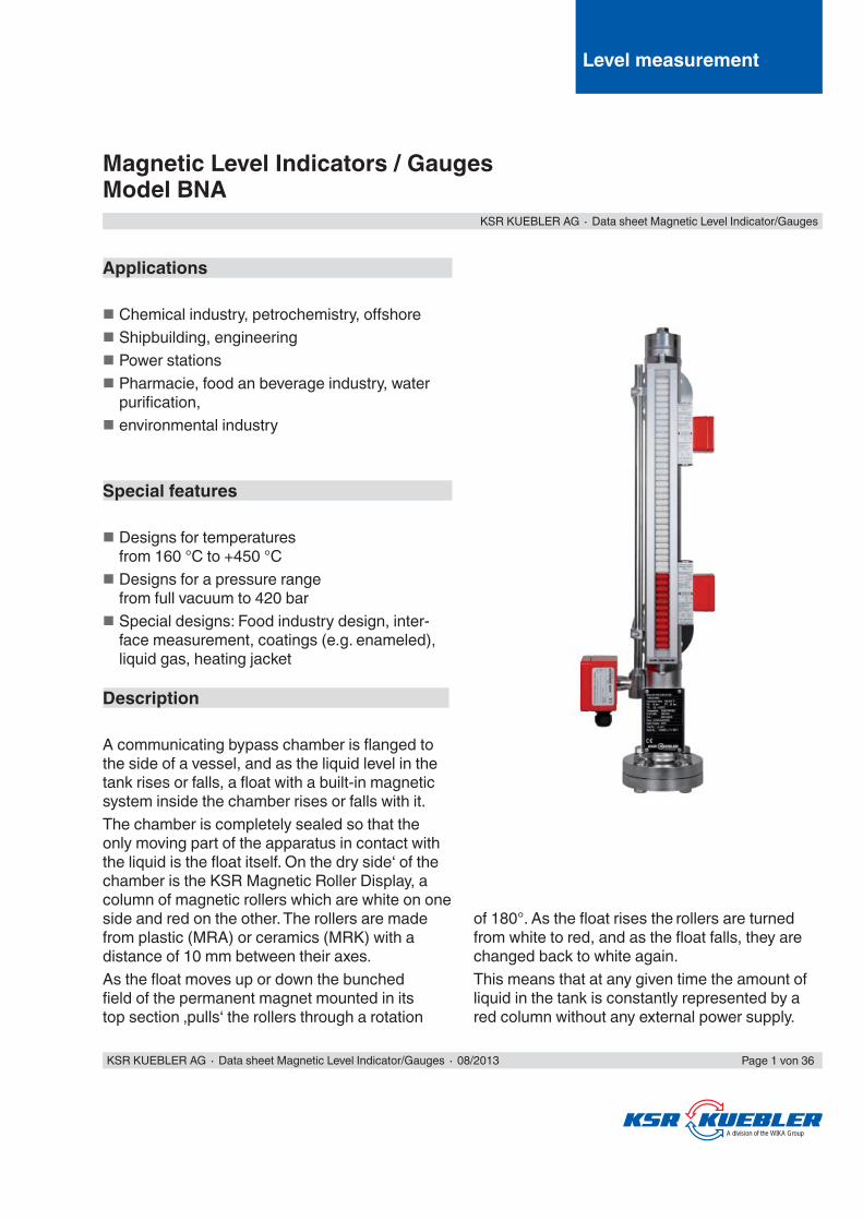
Magnetic Level Indicators / GaugesModel BNA
Applications
Chemical industry, petrochemistry, off shore Shipbuilding, engineering Power stations Pharmacie, food an beverage industry, water purifi cation,
environmental industry
Special features
Designs for temperatures from 160 °C to +450 °C
Designs for a pressure range from full vacuum to 420 bar
Special designs: Food industry design, inter-face measurement, coatings (e.g. enameled), liquid gas, heating jacket
Description
A communicating bypass chamber is fl anged to the side of a vessel, and as the liquid level in the tank rises or falls, a fl oat with a built-in magnetic system inside the chamber rises or falls with it.The chamber is completely sealed so that the only moving part of the apparatus in contact with the liquid is the fl oat itself. On the dry side‘ of the chamber is the KSR Magnetic Roller Display, a column of magnetic rollers which are white on one side and red on the other. The rollers are made from plastic (MRA) or ceramics (MRK) with a distance of 10 mm between their axes.As the fl oat moves up or down the bunched fi eld of the permanent magnet mounted in its top section ‚pulls‘ the rollers through a rotation
of 180°. As the fl oat rises the rollers are turned from white to red, and as the fl oat falls, they are changed back to white again.This means that at any given time the amount of liquid in the tank is constantly represented by a red column without any external power supply.

94/9/EG
TÜV Süd - DGRL 97/23/EG
Germanischer Lloyd
Det Norske Veritas
Rostechnadzor
American Bureau of Shipping
Page 2 of 36 KSR KUEBLER AG ∙ Data sheet Magnetic Level Indicator/Gauges ∙ 08/2013
Technical Advantages
Simple, robust, and solid design Pressure- and gas-proof separation of chamber and display
Measuring and indicating of the level of aggres-sive, combustible, toxic, hot, agitated and contaminated liquids
KSR Magnetic Roller Displays without external power supply
Available for applications in all areas of industry through use of highly corrosion-resistant materials
Approvals
BypassChamper
Magnetic system
KSR MagneticRoller DisplayType MRAKSRBypass fl oat
KSR Magneticswitch
KSR LevelSensorType MG-.......

KSR KUEBLER AG ∙ Data sheet Magnetic Level Indicator/Gauges ∙ 08/2013 Page 3 of 36
Type Code
Code1 Basic type
BNA Magnetic Level Indicator
2 Process connections1st Key = Nom. size 2nd Key = Nom. pressure 3rd Key = Flange face
.../.../... EN... EN 1092 DN 10 - DN 100 ... PN6 - PN400 ... Form B1, B2, C, D... DIN DN 10 - DN 100 PN6 - PN400 Form, C, N, F... ANSI 1/2“ - 4“ Class 150 - Class 400 Form RF, SF, FF, RTJJIS... JIS DN 10 - DN 100 5 K - 63 K Form RF, SF, FF, RTJGN... Thread male DINGM... Thread female DINNPTN... Thread male NPTNPTM... Thrread female NPTS... Welding stubs
3 Option Level Sensor (see separate type code page 25) ... MG Basic type without optional code
Basic type Connectionsize
Optionlevel
sensor
Distancecentre-
tocentre
MaterialChamber
dimensions
MagneticRoller
display
OptionMagnetic
switch
Floatdesign
Certifi cates
Code 1 - 2 - 3 - 4 - 5 - 6 - 7 - 8 - 9
BNA - EN25/16/B1 - MG - M1500 - V60x2 - MRA / SK - 3 / M / 2 - ZVSS185... -
Ordering examples
5 Material and chamber dimensions1st Key = Material 2nd Key = Chamber dimensions
.../..x.. V Stainless steel 1.4571 HC Hastelloy C ..x.. Chamber OD x Wall thickness in mm
L Stainless steel 1.4404 MO SS 1.4529 (6Mo)
VE Stainless steel electro-polished M MonelVTF Stainless steel PTFE-lined PP PolypropyleneVET Stainless steel E-TFE-coated PF PVDFVEC Stainless steel E-CTFE-coated G Borosilicate glass
6 Magnetic Roller Display 1st Key = Design 2nd Key = Scale
.../... MRA Aluminium housing with plastic rollers SK. with scale (plastic), graduation in cm (printed)MRK Aluminium housing with ceramic rollers SA. Aluminium scale gravedMNAV Stainless steel housing with plastic rollers SV. Stainless steel gravedMNKV Stainless steel with ceramic rollers P. with sight glass extender (for insulations))
(weitere Typschlüssel auf Seite 19)7 Option Magnetic Switches 1st Key = Quantity, 3rd Key = Cable length
2nd Key = Execution 3rd Key = Cable length 4th Key = Options.../.../.../... M. BGU MVE. BGU-V-E 1 1 m R22 Pre resistance R22 for SPS
ME. BGU-E MVD. BGU-V-Exd 2 2 m N NAMUR circuitaccording DIN EN 60947-5-6MS12 BGU-M12 MHT BGU-AHT 3 3 m
MES12 BGU-E-M12 MVHT BGU-VHT ... ...MA BGU-A MIL/H BGU-AIL/HMEA BGU-A-E MAR BGU-ARMD. BGU-Exd MAD BGU-ADMV. BGU-V MAM BGU-AM
4 Distance centre-to-centre... M... Distance between fl ange centres in mm
8 Float (cylindrical) 2nd Key = Diameter/Length in mm 1st KEy = Material 3rd Key = Pressure class 4th Key = Magnetic system
Z..S.. .V... Stainless steel 1.4571 .G... Borosilicate glass PN16 PN16 R48H R48H.T... Titanium 3.7035 .VEC... Stainless steel 1.4571
E-CTFE-coatedPN25 PN25 K92 K92
.HC... Hastelloy C ... ... K74 K74
.CF... CF340 .TEC... Titanium 3.7035E-CTFE-coated
A90 A90.PP... Polypropylene A110 A110.PF... PVDF A125 A125
9 Approvals... Ex Ex-Design

~25
90X
M...
U...
U...
M...
90
Page 4 of 36 KSR KUEBLER AG ∙ Data sheet Magnetic Level Indicator/Gauges ∙ 08/2013
Mini Magnetic Level Indicators / GaugesChamber ø 42,4 x 2 mm
Chamber end top RohrbodenOptions: (see page 33)- Vent plug- Vent valve- Vent fl ange
Chamber end bottom Flanged with drain plugOptions: (siehe Seite 33)- Drain valve- Drain fl ange
Process connection Flange EN 1092-1, DN10 - DN50, PN6 - PN40Flange ANSI B 16.5, 1/2“ - 2“ Class 150 - Class 300Thread stubs G/NPT 1/2“ - 1“Welding stubs1/2“ - 1“(Options see page 34)
Distance centre-to-centre M...
Min. 150 mm to max. 5000 mm
Material Stainless steel 1.4571
Nominal pressure Max. 40 bar(entsprechend Schwimmerausführung)
Temperaturbereich Max. 150 °C(according to fl oat design)
Float Type ZVS 32, ZTS 32Material stainless steel 1.4571, Titanium 3.7035S.G. min. 490 kg/m³Type ZBS35/120Type key see page 16,18Material BunaS.G. min. 800 kg/m³Pressure max. 6 barTemperature max. 80 °C
Magnetic roller display Type MRA...for technical data and further designsand options see page 20-21
Further options:Magnetic switchesLevel sensors
see page 22-27see page 28-32
M = Centre-to-centre process con-nectionU = Length of fl oat (min. 200 mm)X = Dep. on process connection
Mini-Bypass Magnetic Level Indicators / Gauges of stainless steel PN40Design: BNA - ../.. - M.... - V42x2 - MRAPressure Equipment Directive 97/23/EG

KSR KUEBLER AG ∙ Data sheet Magnetic Level Indicator/Gauges ∙ 08/2013 Page 5 of 36
PN6 - PN40Chamber ø 60,3 x 2 mm
Chamber end top Welding cap or fl at topor fl angedOptions: (see page 33)- Vent plug- Vent valve- Vent fl ange
Chamber end bottom Flangedwith drain plugOptions: (see page 33)- Drain valve- Drain fl ange
Process connection Flange EN 1092-1, DN10 - DN100, PN6 - PN40Flange ANSI B 16.5, 1/2“ - 4“ Class 150 - Class 300Thread stubs G/NPT 1/2“ - 1“Welding stubs 1/2“ - 1“(Options see page 34)
Distancecentre-to-centre M...
min. 150 mm to max. 6000 mm(other dimensions on request)
Material Stainless steel (316 Ti, 316 L, 904 L)Titanium Grade 2Hastelloy C
Nominal pressure Max. 40 bar(according to fl ange design)
Temperature range -160 °C to +450 °C(according to design)
Float Titan Grade 2Stainless steel 316TiFloat design according to process parameters S.G., pressure and temperature (see type code page 16-18)
Magnetic roller display Typ MRA-M... < 200 °CTyp MRK-M... > 200 °Cfor technical data and further designsand options see page 20-21
Further options:Magnetic switchesLevel sensorsElectrical trace heatingChamber insulation
see page 22-27see page 28-32on requeston request
Explosion protection (Option)
Ex II 1/2G c T1-T6 KEMA 02 ATEX 2106 X
Other designs on request
Bypass Magnetic Level Indicators / Gauges PN6 - PN40Design: BNA - ../.. - M.... - ..x.. - MRA (-Ex)Pressure Equipment Directive 97/23/EG
M = Centre-to-centre process con-nectionU = Length of fl oat (min. 200 respec-tively 220 mm)X = Dep. on process connection

150
UM.
..10
0~6
3
~51
Page 6 of 36 KSR KUEBLER AG ∙ Data sheet Magnetic Level Indicator/Gauges ∙ 08/2013
PN63 and PN100Chamber PN63 PN100
ø 60,3 x 2 mm oder ø 60,3 x 2,6 mmø 65 x 3,5 mm
Chamber end top PN63 PN100
Welding cap or fl at top or fl angedDN50 PN63 bzw. ANSI 2“ Class 600DN50 PN100 bzw. ANSI 2“ Class 600Options: (siehe Seite 30)- Entlüftungsschraube - Entlüftungsventil- Entlüftungsfl ansch
Unterer Standrohrab-schluss PN63 PN100
FlanschverbindungDN50 PN63 bzw. ANSI 2“ Class 600DN50 PN100 bzw. ANSI 2“ Class 600mit AblassschraubeOptionen: (siehe Seite 30)- Vent valve- Vent fl ange
Process connection Flange EN 1092-1, DN10 - DN100, PN63 - PN100Flange ANSI B 16.5, 1/2“ - 4“ Class 600Thread stubs G/NPT 1/2“ - 1“Welding stubs 1/2“ - 1“(Options see page 31)
Distance centre-to-centre M...
Min. 150 mm to max. 6000 mm(other dimensions on request)
Material Stainless steel 1.4571
Nominal pressure PN63 PN100
Max. 63 barMax. 100 bar
Temperature range -30 °C to +300 °C(according to design)
Float Titan Grade 2Float design according to process parameters S.G., pressure and temperature (see type code page 19 and 20)
Magnetic roller display Type MRA... < 200 °CType MRK... > 200 °Cfor technical data and further designsand options see page 20-21
Further options:Magnetic switchesLevel sensorsElectrical trace heatingChamber insulation
See page 22-27See page 28-32on requeston request
Explosion protection (Option)
Ex II 1/2G c T1-T6 KEMA 02 ATEX 2106 X
Other designs on request
Bypass Magnetic Level Indicators / Gauges PN63 and PN100 of stainless steelDesign: BNA - ../.. - M.... - V..x.. - MRA (-Ex)Pressure Equipment Directive 97/23/EG
M = Centre-to-centre process con-nectionU = Length of fl oat (min. 220 mm)
PN63 PN 100

180 (PN160)210 (PN250)
U09~
...M
001
KSR KUEBLER AG ∙ Data sheet Magnetic Level Indicator/Gauges ∙ 08/2013 Page 7 of 36
PN160 and PN250Chamber PN160 PN250
ø 73,03 x 5,16 mmø 71 x 7,5 mm
Chamber end top Flat top or fl angedANSI 2 1/2“ Class 1500Options: (see page 30)- Vent plug- Vent valve- Vent fl ange
Chamber end bottom FlangedANSI 2 1/2“ Class 1500with drain plugOptions: (see page 30)- Drain valve- Drain fl ange
Process connection Flange EN 1092-1, DN10 - DN50, PN160 - PN250Flange ANSI B 16.5, 1/2“ - 2“ Class 1500Thread stubs G/NPT 1/2“ - 1“Welding stubs 1/2“ - 1“(Options see page 31)
Distance centre-to-centre M...
Min. 150 mm to max. 6000 mm(other dimensions on request)
Material Stainless steel 1.4571
Nominal pressure PN160 PN250
Max. 160 barMax. 250 bar
Temperature range PN160 PN250
-30 °C bis +285 °C-30 °C bis +200 °C(according to design)
Float Titan Grade 2Float design according to process parameters S.G., pressure and temperature (see type code page 18)CF 340 solid body material, leakage-proof
Magnetic roller display Typ MRA... < 200 °CTyp MRK... > 200 °CTechnische Daten und weiterefor technical data and further designsand options see page 20-21
Further options:Magnetic switchesLevel sensorsElectrical trace heatingChamber insulation
See page 22-27See page 28-32on requeston request
Explosion protection (Option)
Ex II 1/2G c T1-T6 KEMA 02 ATEX 2106 X
Other designs on request
Bypass Magnetic Level Indicators / Gauges PN160 and PN250 of stainless steelDesign: BNA - ../.. - M.... - V..x.. - MRA (-Ex)Pressure Equipment Directive 97/23/EG
M = Centre-to-centre process con-nectionU = Length of fl oat (min. 220 mm)
501~U
...M
021
210
Page 8 of 36 KSR KUEBLER AG ∙ Data sheet Magnetic Level Indicator/Gauges ∙ 08/2013
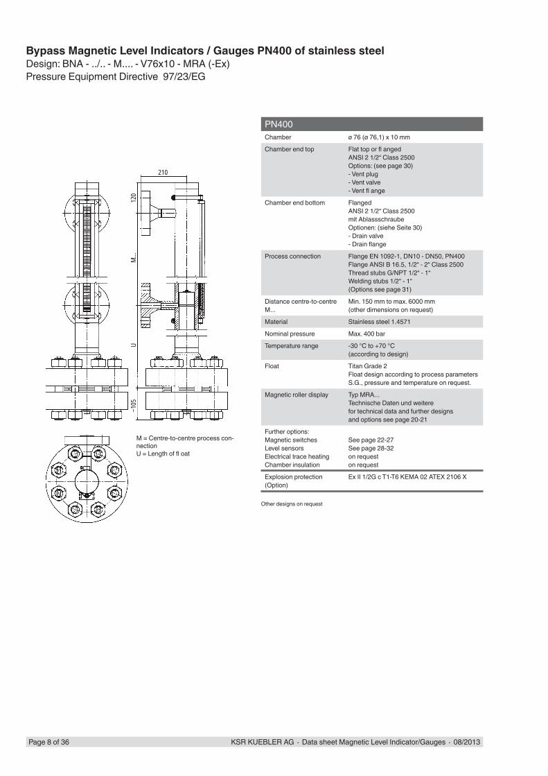
PN400Chamber ø 76 (ø 76,1) x 10 mm
Chamber end top Flat top or fl angedANSI 2 1/2“ Class 2500Options: (see page 30)- Vent plug- Vent valve- Vent fl ange
Chamber end bottom FlangedANSI 2 1/2“ Class 2500mit AblassschraubeOptionen: (siehe Seite 30)- Drain valve- Drain fl ange
Process connection Flange EN 1092-1, DN10 - DN50, PN400Flange ANSI B 16.5, 1/2“ - 2“ Class 2500Thread stubs G/NPT 1/2“ - 1“Welding stubs 1/2“ - 1“(Options see page 31)
Distance centre-to-centre M...
Min. 150 mm to max. 6000 mm(other dimensions on request)
Material Stainless steel 1.4571
Nominal pressure Max. 400 bar
Temperature range -30 °C to +70 °C(according to design)
Float Titan Grade 2Float design according to process parameters S.G., pressure and temperature on request.
Magnetic roller display Typ MRA...Technische Daten und weiterefor technical data and further designsand options see page 20-21
Further options:Magnetic switchesLevel sensorsElectrical trace heatingChamber insulation
See page 22-27See page 28-32on requeston request
Explosion protection (Option)
Ex II 1/2G c T1-T6 KEMA 02 ATEX 2106 X
Other designs on request
Bypass Magnetic Level Indicators / Gauges PN400 of stainless steelDesign: BNA - ../.. - M.... - V76x10 - MRA (-Ex)Pressure Equipment Directive 97/23/EG
M = Centre-to-centre process con-nectionU = Length of fl oat
KSR KUEBLER AG ∙ Data sheet Magnetic Level Indicator/Gauges ∙ 08/2013 Page 9 of 36
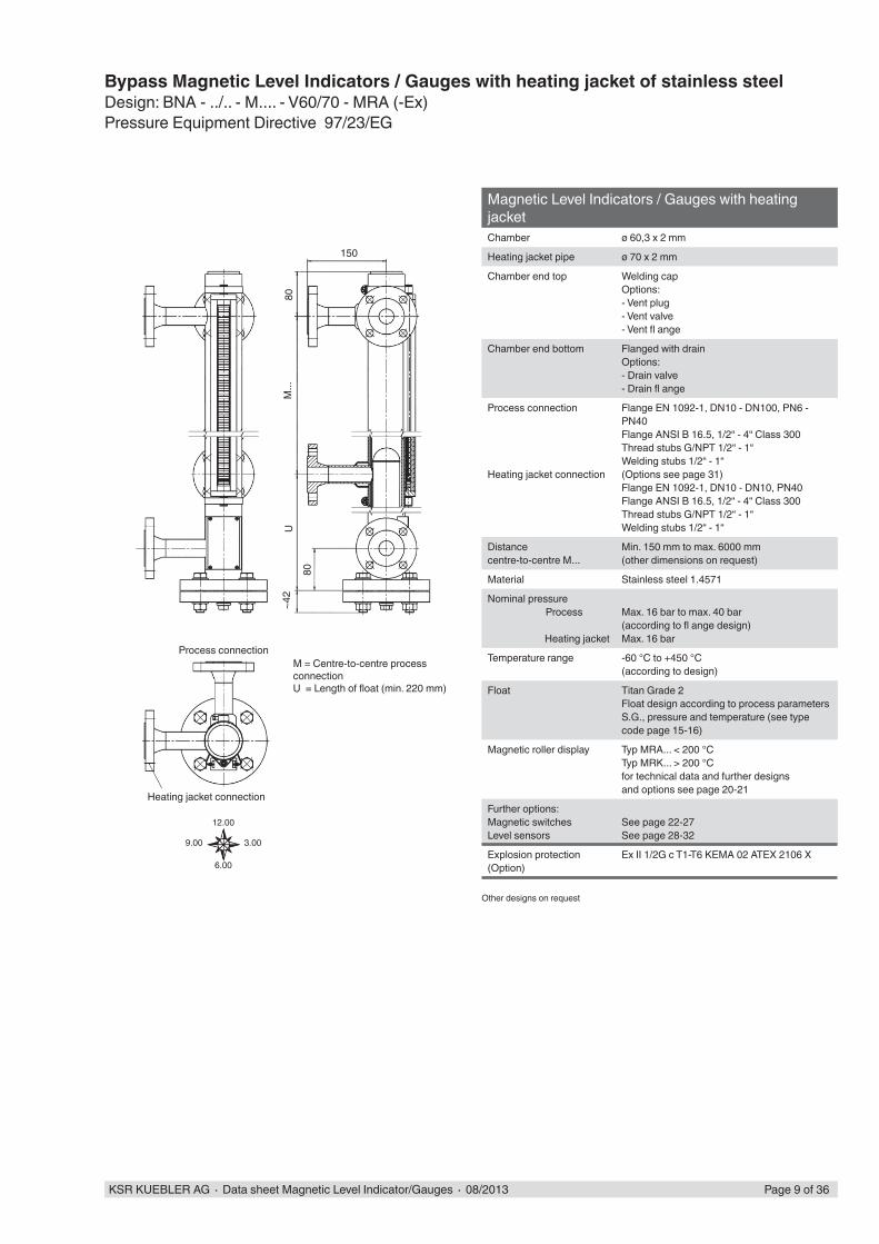
Magnetic Level Indicators / Gauges with heating jacketChamber ø 60,3 x 2 mm
Heating jacket pipe ø 70 x 2 mm
Chamber end top Welding capOptions: - Vent plug- Vent valve- Vent fl ange
Chamber end bottom Flanged with drainOptions:- Drain valve- Drain fl ange
Process connection
Heating jacket connection
Flange EN 1092-1, DN10 - DN100, PN6 - PN40Flange ANSI B 16.5, 1/2“ - 4“ Class 300 Thread stubs G/NPT 1/2“ - 1“Welding stubs 1/2“ - 1“(Options see page 31)Flange EN 1092-1, DN10 - DN10, PN40Flange ANSI B 16.5, 1/2“ - 4“ Class 300 Thread stubs G/NPT 1/2“ - 1“Welding stubs 1/2“ - 1“
Distancecentre-to-centre M...
Min. 150 mm to max. 6000 mm(other dimensions on request)
Material Stainless steel 1.4571
Nominal pressure Process
Heating jacket
Max. 16 bar to max. 40 bar(according to fl ange design)Max. 16 bar
Temperature range -60 °C to +450 °C(according to design)
Float Titan Grade 2Float design according to process parameters S.G., pressure and temperature (see type code page 15-16)
Magnetic roller display Typ MRA... < 200 °CTyp MRK... > 200 °Cfor technical data and further designsand options see page 20-21
Further options:Magnetic switchesLevel sensors
See page 22-27See page 28-32
Explosion protection (Option)
Ex II 1/2G c T1-T6 KEMA 02 ATEX 2106 X
Other designs on request
Bypass Magnetic Level Indicators / Gauges with heating jacket of stainless steelDesign: BNA - ../.. - M.... - V60/70 - MRA (-Ex)Pressure Equipment Directive 97/23/EG
M = Centre-to-centre process connectionU = Length of fl oat (min. 220 mm)
Process connection
Heating jacket connection
80
150
M...
U~4
2
80
12.00
3.00
6.00
9.00

Page 10 of 36 KSR KUEBLER AG ∙ Data sheet Magnetic Level Indicator/Gauges ∙ 08/2013
Liquid Gas DesignChamber ø 88,9 x 2 mm
Chamber end top FlangedOptions: (see page 30)- Vent plug- Vent valve- Vent fl ange
Chamber end bottom Flangedwith drain plugOptions: (page 30)- Drain valve- Drain fl ange
Process connection Flange ANSI B 16.5, 1/2“ - 4“ Class 150 - Class 300Thread stubs G/NPT 1/2“ - 1“Flange EN 1092-1, DN10 - DN100, PN6 - PN40Welding stubs 1/2“ - 1“(Options see page 31)
Distancecentre-to-centre M...
Min. 150 mm to max. 6000 mm
Material Stainless steel 1.4571
Nominal pressure Max. 25 bar(according to fl ange design)
Temperature range -60 °C to +300 °C(according to design)
Float Titan Grade 2Float design according to process parameters S.G., pressure and temperature (see type code page 15)
Magnetic roller display Typ MRA... < 200 °CTyp MRK... > 200 °Cfor technical data and further designsand options see page 20-21
Further options:Magnetic switchesLevel sensorsElectrical trace heatingChamber insulation
See page 22-27See page 28-32on requeston request
Explosion protection (Option)
Ex II 1/2G c T1-T6 KEMA 02 ATEX 2106 X
Other designs on request
Bypass Magnetic Level Indicators / Gauges in Liquid Gas Design of stainless steelDesign: BNA - ../.. - M.... - V88x2 - MRA (-Ex)Pressure Equipment Directive 97/23/EG
M = Centre-to-centre process connec-tionU = Length of fl oat (min. 220 mm)
~42
150
80U
M...
~42
A A
A-A

~ 35
UM.
..~ 5
0150
130
KSR KUEBLER AG ∙ Data sheet Magnetic Level Indicator/Gauges ∙ 08/2013 Page 11 of 36
E-CTFE-coatedChamber ø 64 x 2 mm
Chamber end top FlangedOptions: - Vent fl ange
Chamber end bottom FlanschverbindungOptions: - drain fl ange
Process connection Flange EN 1092-1, DN10 - DN100, PN16Flange ANSI B 16.5, 1/2“ - 4“ Class 150 - Class 300
Distancecentre-to-centre M...
Min. 150 mm to max. ... mm(overall chamber length max. 2500 mm)on dimensions > 2500 mm- chamber separated with fl ange
Material Stainless steel 316 Ti (1.4571)coated E-CTFE internally, Option: anti-static
Nominal pressure Max. 16 bar
Temperature range depending on liquid
Float Stainless steel 316Ti E-CTFE-coatedTitanium Grade 2 E-CTFE-coatedFloat design according to process parameters S.G., pressure and temperature (see type code page 15)
Magnetic roller display Typ MRA...for technical data and further designsand options see page 20-21
Further options:Magnetic switchesLevel sensors
See page 22-27See page 28-32
Other designs on request
Bypass Magnetic Level Indicators / Gauges E-CT-FE-coatedDesign: BNA - ../16 - M....-VEC64x2 - MRAPressure Equipment Directive 97/23/EG
M = Centre-to-centre process con-nectionU = Length of fl oat (min. 220 mm)
150
~35
150
~50
U =
...M
= ...
Page 12 of 36 KSR KUEBLER AG ∙ Data sheet Magnetic Level Indicator/Gauges ∙ 08/2013
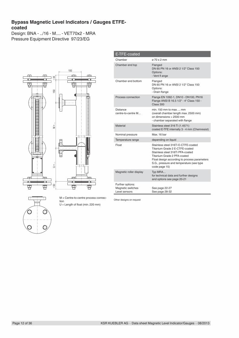
E-TFE-coatedChamber ø 70 x 2 mm
Chamber end top FlangedDN 65 PN 16 or ANSI 2 1/2“ Class 150Options:- Vent fl ange
Chamber end bottom FlangedDN 65 PN 16 or ANSI 2 1/2“ Class 150Options: - Drain fl ange
Process connection Flange EN 1092-1, DN10 - DN100, PN16Flange ANSI B 16.5 1/2“ - 4“ Class 150 - Class 300
Distancecentre-to-centre M...
min. 150 mm to max. ... mm(overall chamber length max. 2500 mm)on dimensions > 2500 mm- chamber separated with fl ange
Material Stainless steel 316 Ti (1.4571)coated E-TFE internally 3 - 4 mm (Chemresist)
Nominal pressure Max. 16 bar
Temperature range depending on liquid
Float Stainless steel 316Ti E-CTFE-coatedTitanium Grade 2 E-CTFE-coatedStainless steel 316Ti PFA-coatedTitanium Grade 2 PFA-coatedFloat design according to process parameters S.G., pressure and temperature (see type code page 15)
Magnetic roller display Typ MRA...for technical data and further designsand options see page 20-21
Further options:Magnetic switchesLevel sensors
See page 22-27See page 28-32
Other designs on request
Bypass Magnetic Level Indicators / Gauges ETFE-coatedDesign: BNA - ../16 - M.... - VET70x2 - MRAPressure Equipment Directive 97/23/EG
M = Centre-to-centre process connec-tionU = Length of fl oat (min. 220 mm)

KSR KUEBLER AG ∙ Data sheet Magnetic Level Indicator/Gauges ∙ 08/2013 Page 13 of 36
PTFE-linedChamber ø 70 x 2 mm
Chamber end top FlangedOptions: - Vent fl ange
Chamber end bottom FlangedOptions: - Drain fl ange
Process connection Flange EN 1092-1, DN25, PN16Flange ANSI B 16.5, 1“ Class 150 - Class 300
Distancecentre-to-centre M...
min. 150 mm to max. ... mm(overall chamber length max. 2000 mon dimensions > 2000 mm- chamber separated with fl ange
Material Stainless steel 316 Ti (1.4571) coated PTFE internallyLining: 3 mm wall thickness, vacuum-proofOption: anti-static
Nominal pressure Max. 10 bar
Temperature range depending on liquid
Float Stainless steel 316Ti E-CTFE-coatedTitanium Grade 2 E-CTFE-coatedStainless steel 316Ti PFA-coatedTitanium Grade 2 PFA-coatedFloat design according to process parameters S.G., pressure and temperature (see type code page 15)
Magnetic roller display Typ MRA...for technical data and further designsand options see page 20-21
Further options:Magnetic switchesLevel sensors
See page 22-27See page 28-32
Other designs on request
Bypass Magnetic Level Indicators / Gauges PTFE-linedDesign: BNA - ../16 - M.... - VTF70x2 - MRAPressure Equipment Directive 97/23/EG
M = Centre-to-centre process connectionU = Length of fl oat (min. 220 mm)
15515
0U
M...
~45

135
170
M...
U
Page 14 of 36 KSR KUEBLER AG ∙ Data sheet Magnetic Level Indicator/Gauges ∙ 08/2013
Magnetic Level Indicators / Gauges PVDF, PP Chamber ø 63 x 3 mm
Chamber end top Welding capOptions: - Threaded fi tting- Vent valve- Vent fl ange
Chamber end bottom Threaded fi ttingOptions:- Drain valve- Drain fl ange
Process connection Flange EN 1092-1, DN10 - DN50 PN6 - PN 16Flange ANSI B 16.5, 1/2“ - 2“ Class 150Welding stubs 1/2“ - 1“
Distance centre-to-centre M...
Min. 200 mm to max. 4000 mm
Material PVDF, PP
Nominal pressure Max. 4 bar
Temperature range PVDF max. 80 °CPP max. 60 °C
Float PVDFPPFloat design according to type code (see page 15)
Magnetic roller display Typ MRA....for technical data and further designsand options see page 20-21
Further options:Magnetic switchesLevel sensors
See page 22-27See page 28-32
Other designs on request
Bypass Magnetic Level Indicators / Gauges of PVDF, PPDesign: BNA - ../16 - M.... - PF63x3 - MRA BNA - ../16 - M.... - PP63x3 - MRA
M = Centre-to-centre process connectionU = Length of fl oat (mind. 155 mm)
D
L
Z.SS
D
L
ZTKS
D
L
Z.S
D
L
ZPS
D
L
ZCFS
DD DDD
L L L L L
KSR KUEBLER AG ∙ Data sheet Magnetic Level Indicator/Gauges ∙ 08/2013 Page 15 of 36
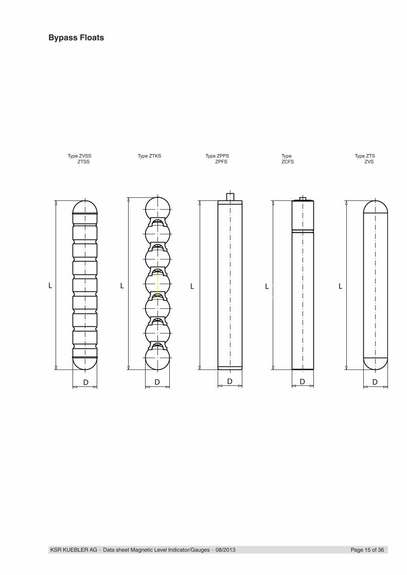
Type ZVSS ZTSS
Type ZTKS Type ZPPS ZPFS
Type ZCFS
Type ZTS ZVS
Bypass Floats
Page 16 of 36 KSR KUEBLER AG ∙ Data sheet Magnetic Level Indicator/Gauges ∙ 08/2013
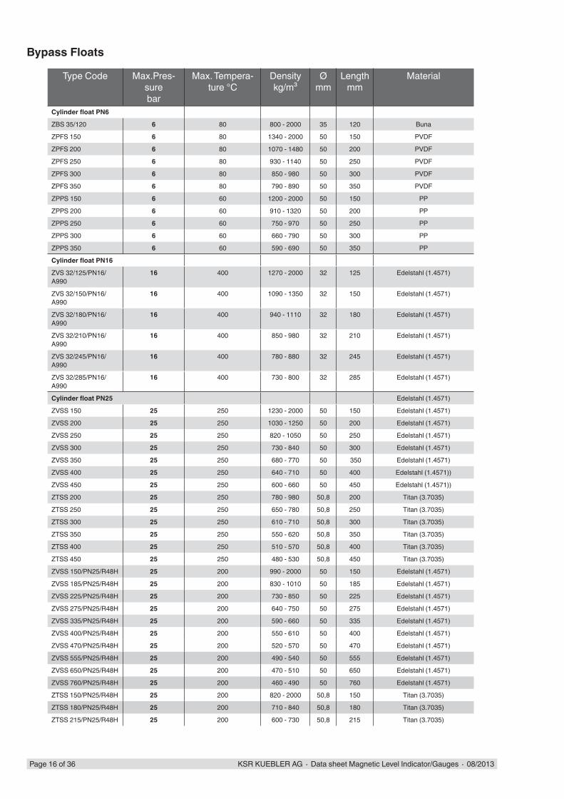
Bypass Floats
Type Code Max.Pres-sure bar
Max. Tempera-ture °C
Densitykg/m³
Ømm
Lengthmm
Material
Cylinder fl oat PN6
ZBS 35/120 6 80 800 - 2000 35 120 Buna
ZPFS 150 6 80 1340 - 2000 50 150 PVDF
ZPFS 200 6 80 1070 - 1480 50 200 PVDF
ZPFS 250 6 80 930 - 1140 50 250 PVDF
ZPFS 300 6 80 850 - 980 50 300 PVDF
ZPFS 350 6 80 790 - 890 50 350 PVDF
ZPPS 150 6 60 1200 - 2000 50 150 PP
ZPPS 200 6 60 910 - 1320 50 200 PP
ZPPS 250 6 60 750 - 970 50 250 PP
ZPPS 300 6 60 660 - 790 50 300 PP
ZPPS 350 6 60 590 - 690 50 350 PP
Cylinder fl oat PN16
ZVS 32/125/PN16/A990
16 400 1270 - 2000 32 125 Edelstahl (1.4571)
ZVS 32/150/PN16/A990
16 400 1090 - 1350 32 150 Edelstahl (1.4571)
ZVS 32/180/PN16/A990
16 400 940 - 1110 32 180 Edelstahl (1.4571)
ZVS 32/210/PN16/A990
16 400 850 - 980 32 210 Edelstahl (1.4571)
ZVS 32/245/PN16/A990
16 400 780 - 880 32 245 Edelstahl (1.4571)
ZVS 32/285/PN16/A990
16 400 730 - 800 32 285 Edelstahl (1.4571)
Cylinder fl oat PN25 Edelstahl (1.4571)
ZVSS 150 25 250 1230 - 2000 50 150 Edelstahl (1.4571)
ZVSS 200 25 250 1030 - 1250 50 200 Edelstahl (1.4571)
ZVSS 250 25 250 820 - 1050 50 250 Edelstahl (1.4571)
ZVSS 300 25 250 730 - 840 50 300 Edelstahl (1.4571)
ZVSS 350 25 250 680 - 770 50 350 Edelstahl (1.4571)
ZVSS 400 25 250 640 - 710 50 400 Edelstahl (1.4571))
ZVSS 450 25 250 600 - 660 50 450 Edelstahl (1.4571))
ZTSS 200 25 250 780 - 980 50,8 200 Titan (3.7035)
ZTSS 250 25 250 650 - 780 50,8 250 Titan (3.7035)
ZTSS 300 25 250 610 - 710 50,8 300 Titan (3.7035)
ZTSS 350 25 250 550 - 620 50,8 350 Titan (3.7035)
ZTSS 400 25 250 510 - 570 50,8 400 Titan (3.7035)
ZTSS 450 25 250 480 - 530 50,8 450 Titan (3.7035)
ZVSS 150/PN25/R48H 25 200 990 - 2000 50 150 Edelstahl (1.4571)
ZVSS 185/PN25/R48H 25 200 830 - 1010 50 185 Edelstahl (1.4571)
ZVSS 225/PN25/R48H 25 200 730 - 850 50 225 Edelstahl (1.4571)
ZVSS 275/PN25/R48H 25 200 640 - 750 50 275 Edelstahl (1.4571)
ZVSS 335/PN25/R48H 25 200 590 - 660 50 335 Edelstahl (1.4571)
ZVSS 400/PN25/R48H 25 200 550 - 610 50 400 Edelstahl (1.4571)
ZVSS 470/PN25/R48H 25 200 520 - 570 50 470 Edelstahl (1.4571)
ZVSS 555/PN25/R48H 25 200 490 - 540 50 555 Edelstahl (1.4571)
ZVSS 650/PN25/R48H 25 200 470 - 510 50 650 Edelstahl (1.4571)
ZVSS 760/PN25/R48H 25 200 460 - 490 50 760 Edelstahl (1.4571)
ZTSS 150/PN25/R48H 25 200 820 - 2000 50,8 150 Titan (3.7035)
ZTSS 180/PN25/R48H 25 200 710 - 840 50,8 180 Titan (3.7035)
ZTSS 215/PN25/R48H 25 200 600 - 730 50,8 215 Titan (3.7035)

KSR KUEBLER AG ∙ Data sheet Magnetic Level Indicator/Gauges ∙ 08/2013 Page 17 of 36
Bypass Floats
Type Code Max. Pres-sure bar
Max. Tempera-ture °C
Density kg/m³
Ømm
Lengthmm
Material
Cylinder fl oat PN25
ZTSS 250/PN25/R48H 25 200 540 - 620 50,8 250 Titan (3.7035)
ZTSS 300/PN25/R48H 25 200 480 - 560 50,8 300 Titan (3.7035)
ZTSS 355/PN25/R48H 25 200 430 - 500 50,8 355 Titan (3.7035)
ZTSS 410/PN25/R48H 25 200 400 - 450 50,8 410 Titan (3.7035)
ZTSS 465/PN25/R48H 25 200 380 - 420 50,8 465 Titan (3.7035)
ZTSS 525/PN25/R48H 25 200 370 - 400 50,8 525 Titan (3.7035)
ZTSS 595/PN25/R48H 25 200 360 - 390 50,8 595 Titan (3.7035)
ZTSS 680/PN25/R48H 25 200 340 - 380 50,8 680 Titan (3.7035)
ZTSS 765/PN25/R48H 25 200 320 - 360 50,8 765 Titan (3.7035)ZVS 200/2,5/200/1160/K74 25 200 1050 - 2000 50 200 Edelstahl (1.4571)ZVS 250/2,5/200/960/K74 25 200 890 - 1170 50 250 Edelstahl (1.4571)ZVS 300/2,5/200/850/K74 25 200 800 - 970 50 300 Edelstahl (1.4571)ZVS 350/2,5/200/775/K74 25 200 740 - 860 50 350 Edelstahl (1.4571)ZVS 400/2,5/200/720/K74 25 200 695 - 810 50 400 Edelstahl (1.4571)ZVS 450/2,5/200/680/K74 25 200 660 - 770 50 450 Edelstahl (1.4571)ZTS 150/2,5/200/1380/K74 25 200 1190 - 2000 50 150 Titan (3.7035)ZTS 200/2,5/200/1000/K74 25 200 910 - 1340 50 200 Titan (3.7035)ZTS 250/2,5/200/830/K74 25 200 770 - 980 50 250 Titan (3.7035)ZTS 300/2,5/200/730/K74 25 200 690 - 810 50 300 Titan (3.7035)ZTS 350/2,5/200/660/K74 25 200 630 - 740 50 350 Titan (3.7035)ZTS 400/2,5/200/610/K74 25 200 590 - 690 50 400 Titan (3.7035)ZTS 450/2,5/200/580/K74 25 200 560 - 650 50 450 Titan (3.7035)ZTS 500/2,5/200/550/K74 25 200 540 - 620 50 500 Titan (3.7035)
Cylinder fl oat PN40
ZTS 150/PN40/K92 40 250 1060 - 2000 50,8 150 Titan (3.7035)
ZTS 180/PN40/K92 40 250 900 - 1080 50,8 180 Titan (3.7035)
ZTS 215/PN40/K92 40 250 780 - 920 50,8 215 Titan (3.7035)
ZTS 255/PN40/K92 40 250 700 - 800 50,8 255 Titan (3.7035)
ZTS 300/PN40/K92 40 250 630 - 720 50,8 300 Titan (3.7035)
ZTS 345/PN40/K92 40 250 580 - 650 50,8 345 Titan (3.7035)
ZTS 405/PN40/K92 40 250 540 - 600 50,8 405 Titan (3.7035)
ZTS 465/PN40/K92 40 250 510 - 560 50,8 465 Titan (3.7035)
ZTS 530/PN40/K92 40 250 490 - 530 50,8 530 Titan (3.7035)
ZTS 610/PN40/K92 40 250 470 - 510 50,8 610 Titan (3.7035)
ZTS 150/PN40/R48H 40 190 900 - 2000 50,8 150 Titan (3.7035)
ZTS 185/PN40/R48H 40 190 760 - 920 50,8 185 Titan (3.7035)
ZTS 225/PN40/R48H 40 190 660 - 780 50,8 225 Titan (3.7035)
ZTS 270/PN40/R48H 40 190 590 - 680 50,8 270 Titan (3.7035)
ZTS 320/PN40/R48H 40 190 540 - 610 50,8 320 Titan (3.7035)
ZTS 385/PN40/R48H 40 190 500 - 560 50,8 385 Titan (3.7035)
ZTS 465/PN40/R48H 40 190 470 - 520 50,8 465 Titan (3.7035)
ZTS 550/PN40/R48H 40 190 450 - 490 50,8 550 Titan (3.7035)
ZTS 635/PN40/R48H 40 190 430 - 470 50,8 635 Titan (3.7035)
ZTS 60/150/PN40/K74 40 200 1060 - 2000 50,8 150 Titan (3.7035)
ZTS 60/180/PN40/K74 40 200 890 - 1070 50,8 180 Titan (3.7035)
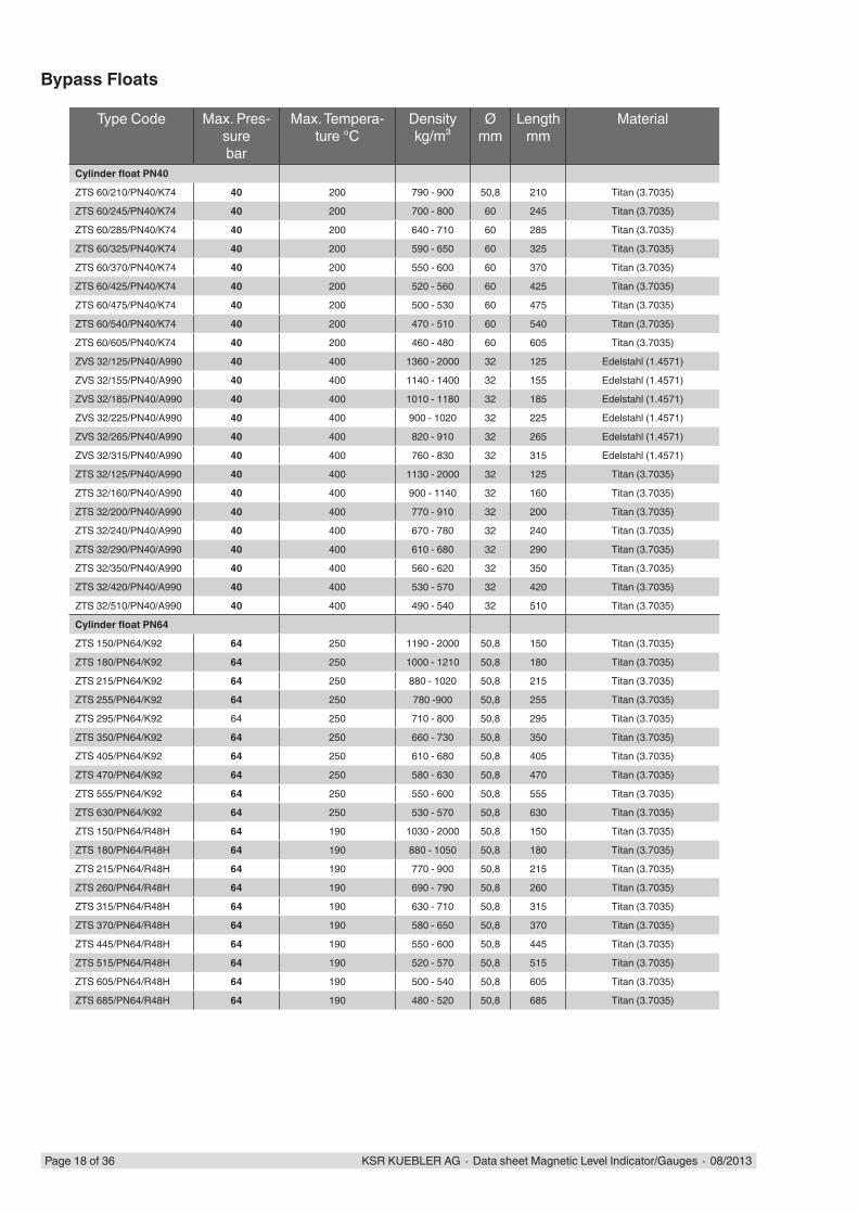
Page 18 of 36 KSR KUEBLER AG ∙ Data sheet Magnetic Level Indicator/Gauges ∙ 08/2013
Bypass Floats
Type Code Max. Pres-sure bar
Max. Tempera-ture °C
Density kg/m³
Ømm
Lengthmm
Material
Cylinder fl oat PN40
ZTS 60/210/PN40/K74 40 200 790 - 900 50,8 210 Titan (3.7035)
ZTS 60/245/PN40/K74 40 200 700 - 800 60 245 Titan (3.7035)
ZTS 60/285/PN40/K74 40 200 640 - 710 60 285 Titan (3.7035)
ZTS 60/325/PN40/K74 40 200 590 - 650 60 325 Titan (3.7035)
ZTS 60/370/PN40/K74 40 200 550 - 600 60 370 Titan (3.7035)
ZTS 60/425/PN40/K74 40 200 520 - 560 60 425 Titan (3.7035)
ZTS 60/475/PN40/K74 40 200 500 - 530 60 475 Titan (3.7035)
ZTS 60/540/PN40/K74 40 200 470 - 510 60 540 Titan (3.7035)
ZTS 60/605/PN40/K74 40 200 460 - 480 60 605 Titan (3.7035)
ZVS 32/125/PN40/A990 40 400 1360 - 2000 32 125 Edelstahl (1.4571)
ZVS 32/155/PN40/A990 40 400 1140 - 1400 32 155 Edelstahl (1.4571)
ZVS 32/185/PN40/A990 40 400 1010 - 1180 32 185 Edelstahl (1.4571)
ZVS 32/225/PN40/A990 40 400 900 - 1020 32 225 Edelstahl (1.4571)
ZVS 32/265/PN40/A990 40 400 820 - 910 32 265 Edelstahl (1.4571)
ZVS 32/315/PN40/A990 40 400 760 - 830 32 315 Edelstahl (1.4571)
ZTS 32/125/PN40/A990 40 400 1130 - 2000 32 125 Titan (3.7035)
ZTS 32/160/PN40/A990 40 400 900 - 1140 32 160 Titan (3.7035)
ZTS 32/200/PN40/A990 40 400 770 - 910 32 200 Titan (3.7035)
ZTS 32/240/PN40/A990 40 400 670 - 780 32 240 Titan (3.7035)
ZTS 32/290/PN40/A990 40 400 610 - 680 32 290 Titan (3.7035)
ZTS 32/350/PN40/A990 40 400 560 - 620 32 350 Titan (3.7035)
ZTS 32/420/PN40/A990 40 400 530 - 570 32 420 Titan (3.7035)
ZTS 32/510/PN40/A990 40 400 490 - 540 32 510 Titan (3.7035)
Cylinder fl oat PN64
ZTS 150/PN64/K92 64 250 1190 - 2000 50,8 150 Titan (3.7035)
ZTS 180/PN64/K92 64 250 1000 - 1210 50,8 180 Titan (3.7035)
ZTS 215/PN64/K92 64 250 880 - 1020 50,8 215 Titan (3.7035)
ZTS 255/PN64/K92 64 250 780 -900 50,8 255 Titan (3.7035)
ZTS 295/PN64/K92 64 250 710 - 800 50,8 295 Titan (3.7035)
ZTS 350/PN64/K92 64 250 660 - 730 50,8 350 Titan (3.7035)
ZTS 405/PN64/K92 64 250 610 - 680 50,8 405 Titan (3.7035)
ZTS 470/PN64/K92 64 250 580 - 630 50,8 470 Titan (3.7035)
ZTS 555/PN64/K92 64 250 550 - 600 50,8 555 Titan (3.7035)
ZTS 630/PN64/K92 64 250 530 - 570 50,8 630 Titan (3.7035)
ZTS 150/PN64/R48H 64 190 1030 - 2000 50,8 150 Titan (3.7035)
ZTS 180/PN64/R48H 64 190 880 - 1050 50,8 180 Titan (3.7035)
ZTS 215/PN64/R48H 64 190 770 - 900 50,8 215 Titan (3.7035)
ZTS 260/PN64/R48H 64 190 690 - 790 50,8 260 Titan (3.7035)
ZTS 315/PN64/R48H 64 190 630 - 710 50,8 315 Titan (3.7035)
ZTS 370/PN64/R48H 64 190 580 - 650 50,8 370 Titan (3.7035)
ZTS 445/PN64/R48H 64 190 550 - 600 50,8 445 Titan (3.7035)
ZTS 515/PN64/R48H 64 190 520 - 570 50,8 515 Titan (3.7035)
ZTS 605/PN64/R48H 64 190 500 - 540 50,8 605 Titan (3.7035)
ZTS 685/PN64/R48H 64 190 480 - 520 50,8 685 Titan (3.7035)
KSR KUEBLER AG ∙ Data sheet Magnetic Level Indicator/Gauges ∙ 08/2013 Page 19 of 36
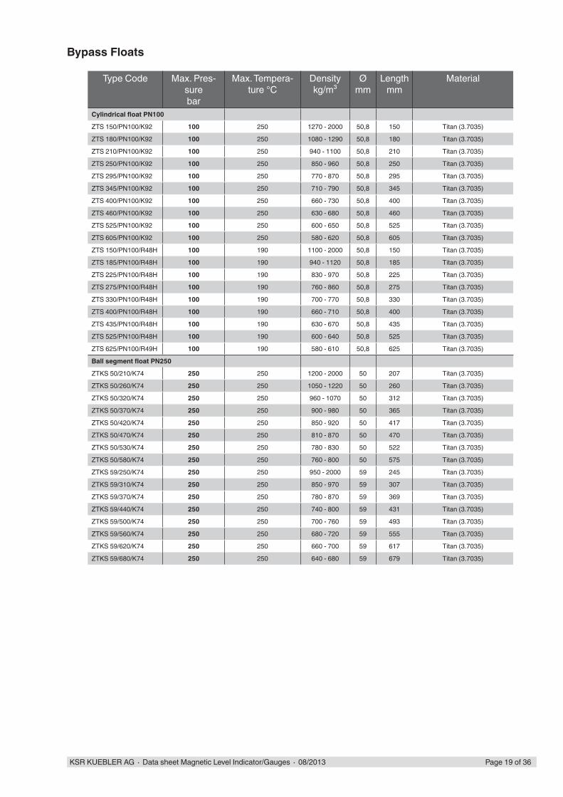
Bypass Floats
Type Code Max. Pres-sure bar
Max. Tempera-ture °C
Density kg/m³
Ømm
Lengthmm
Material
Cylindrical fl oat PN100
ZTS 150/PN100/K92 100 250 1270 - 2000 50,8 150 Titan (3.7035)
ZTS 180/PN100/K92 100 250 1080 - 1290 50,8 180 Titan (3.7035)
ZTS 210/PN100/K92 100 250 940 - 1100 50,8 210 Titan (3.7035)
ZTS 250/PN100/K92 100 250 850 - 960 50,8 250 Titan (3.7035)
ZTS 295/PN100/K92 100 250 770 - 870 50,8 295 Titan (3.7035)
ZTS 345/PN100/K92 100 250 710 - 790 50,8 345 Titan (3.7035)
ZTS 400/PN100/K92 100 250 660 - 730 50,8 400 Titan (3.7035)
ZTS 460/PN100/K92 100 250 630 - 680 50,8 460 Titan (3.7035)
ZTS 525/PN100/K92 100 250 600 - 650 50,8 525 Titan (3.7035)
ZTS 605/PN100/K92 100 250 580 - 620 50,8 605 Titan (3.7035)
ZTS 150/PN100/R48H 100 190 1100 - 2000 50,8 150 Titan (3.7035)
ZTS 185/PN100/R48H 100 190 940 - 1120 50,8 185 Titan (3.7035)
ZTS 225/PN100/R48H 100 190 830 - 970 50,8 225 Titan (3.7035)
ZTS 275/PN100/R48H 100 190 760 - 860 50,8 275 Titan (3.7035)
ZTS 330/PN100/R48H 100 190 700 - 770 50,8 330 Titan (3.7035)
ZTS 400/PN100/R48H 100 190 660 - 710 50,8 400 Titan (3.7035)
ZTS 435/PN100/R48H 100 190 630 - 670 50,8 435 Titan (3.7035)
ZTS 525/PN100/R48H 100 190 600 - 640 50,8 525 Titan (3.7035)
ZTS 625/PN100/R49H 100 190 580 - 610 50,8 625 Titan (3.7035)
Ball segment fl oat PN250
ZTKS 50/210/K74 250 250 1200 - 2000 50 207 Titan (3.7035)
ZTKS 50/260/K74 250 250 1050 - 1220 50 260 Titan (3.7035)
ZTKS 50/320/K74 250 250 960 - 1070 50 312 Titan (3.7035)
ZTKS 50/370/K74 250 250 900 - 980 50 365 Titan (3.7035)
ZTKS 50/420/K74 250 250 850 - 920 50 417 Titan (3.7035)
ZTKS 50/470/K74 250 250 810 - 870 50 470 Titan (3.7035)
ZTKS 50/530/K74 250 250 780 - 830 50 522 Titan (3.7035)
ZTKS 50/580/K74 250 250 760 - 800 50 575 Titan (3.7035)
ZTKS 59/250/K74 250 250 950 - 2000 59 245 Titan (3.7035)
ZTKS 59/310/K74 250 250 850 - 970 59 307 Titan (3.7035)
ZTKS 59/370/K74 250 250 780 - 870 59 369 Titan (3.7035)
ZTKS 59/440/K74 250 250 740 - 800 59 431 Titan (3.7035)
ZTKS 59/500/K74 250 250 700 - 760 59 493 Titan (3.7035)
ZTKS 59/560/K74 250 250 680 - 720 59 555 Titan (3.7035)
ZTKS 59/620/K74 250 250 660 - 700 59 617 Titan (3.7035)
ZTKS 59/680/K74 250 250 640 - 680 59 679 Titan (3.7035)
...L
...M
32
94
...L
...M
5,42
5,63
Page 20 of 36 KSR KUEBLER AG ∙ Data sheet Magnetic Level Indicator/Gauges ∙ 08/2013
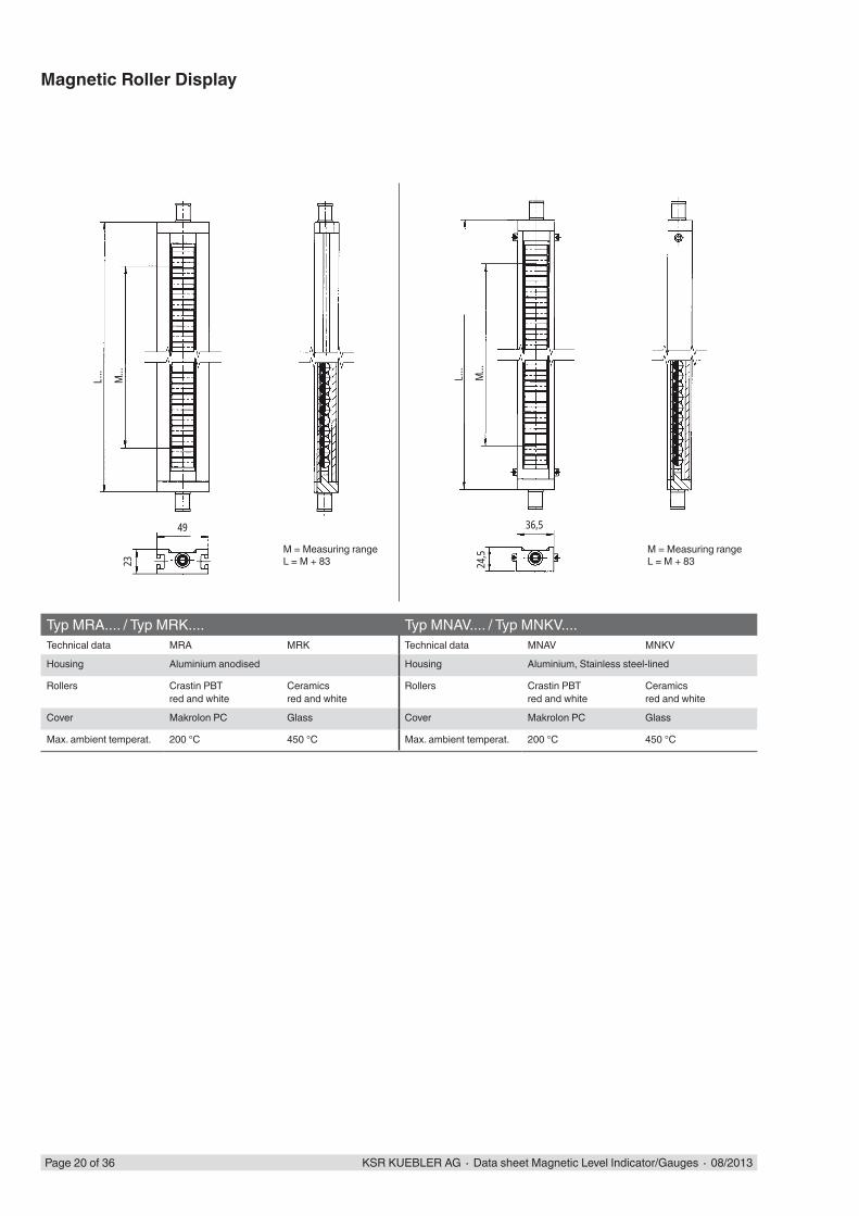
M = Measuring rangeL = M + 83
Typ MRA.... / Typ MRK.... Typ MNAV.... / Typ MNKV....Technical data MRA MRK Technical data MNAV MNKV
Housing Aluminium anodised Housing Aluminium, Stainless steel-lined
Rollers Crastin PBTred and white
Ceramicsred and white
Rollers Crastin PBTred and white
Ceramicsred and white
Cover Makrolon PC Glass Cover Makrolon PC Glass
Max. ambient temperat. 200 °C 450 °C Max. ambient temperat. 200 °C 450 °C
Magnetic Roller Display
M = Measuring rangeL = M + 83
L...
M...
50
49
23
I
L...
M...
2340 49
KSR KUEBLER AG ∙ Data sheet Magnetic Level Indicator/Gauges ∙ 08/2013 Page 21 of 36
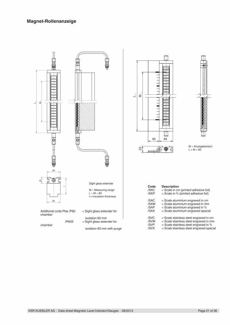
Magnet-Rollenanzeige
M = AnzeigebereichL = M + 83
Code Description /SKC = Scale in cm (printed adhesive foil) /SKP = Scale in % (printed adhesive foil)
/SAC = Scale aluminium engraved in cm /SAM = Scale aluminium engraved in mm /SAP = Scale aluminium engraved in % /SAX = Scale aluminium engraved special
/SVC = Scale stainless steel engraved in cm /SVM = Scale stainless steel engraved in mm /SVP = Scale stainless steel engraved in % /SVX = Scale stainless steel engraved special
Sight glass extender
M = Measuring rangeL = M + 83I = Insulation thickness
Additional code Plex /P60 = Sight glass extender for chamber isolation 60 mm /P60S = Sight glass extender for chamber isolation 60 mm with purge
10k1k
10k
(1)
(2)
(3)
(1)
(2)
(3)
(1)
(2)
(3)
Page 22 of 36 KSR KUEBLER AG ∙ Data sheet Magnetic Level Indicator/Gauges ∙ 08/2013
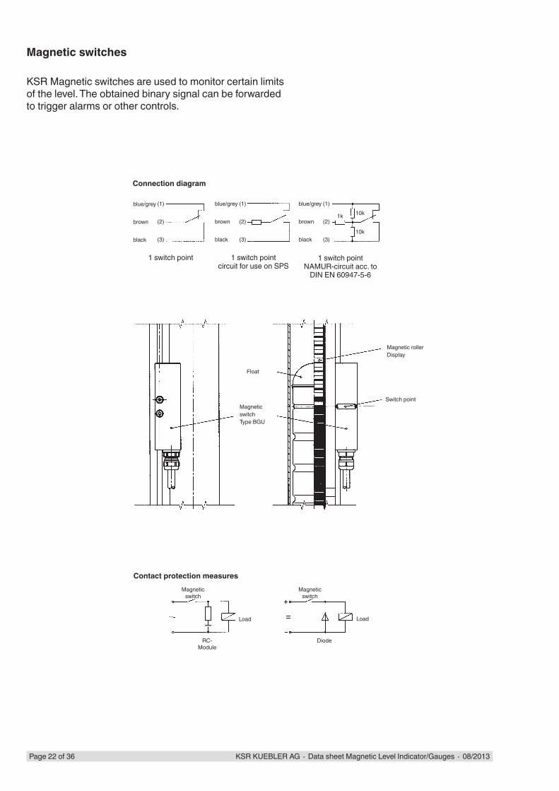
Magnetic switches
KSR Magnetic switches are used to monitor certain limits of the level. The obtained binary signal can be forwarded to trigger alarms or other controls.
blue/grey
brown
black
blue/grey
brown
black
blue/grey
brown
black
Connection diagram
1 switch pointcircuit for use on SPS
1 switch pointNAMUR-circuit acc. to
DIN EN 60947-5-6
1 switch point
MagneticswitchType BGU
Float
Magnetic rollerDisplay
Switch point
Contact protection measuresMagnetic
switch
Diode
Load
Magneticswitch
RC-Module
Load
32 257
504210
016
3225
50
7
4210
016
KSR KUEBLER AG ∙ Data sheet Magnetic Level Indicator/Gauges ∙ 08/2013 Page 23 of 36
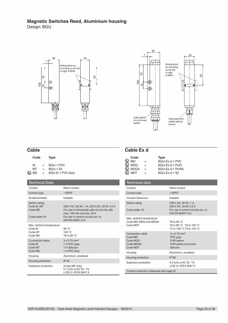
Magnetic Switches Reed, Aluminium housingDesign: BGU
Technical DataContact Reed contact
Contact type 1 SPDT
Schaltverhalten bistable
Switch rating: Code M, MTCode ME
Code adder /N
230 V AC, 60 VA, 1 A; 230 V DC, 30 W, 0.5 AFor use in intrinsically safe circuit only with max. 100 mA und max. 30 VFor use in control circuits acc. to DIN EN 60947-5-6
Max. ambient temperature:Code MCode MTCode ME
90 °C150 °CT6 to 85 °C
Connection cable:Code MCode MTCode ME
3 x 0.75 mm2
1 m PVC grey1 m Silicone1 m PVC blue
Housing Aluminium, anodised
Housing protection IP 65
Explosion protection (Code ME only)II 1 G Ex ia IIC T6 - T3LCIE 01 ATEX 6047 X
Cable
Sliding block for mounting on the left or right of MRA
Technical dataContact Reed contact
Contact type 1 SPDT
Contact behaviour bistable
Switch rating
Code adder /N
230 V AC, 60 VA, 1 A230 V DC, 30 W, 0.5 AFor use in control circuits acc. to DIN EN 60947-5-6
Max. ambient temperatureCode MD, MDG and MDGACode MDT
T6 to 85 °CT6 to 85 °C T5 to 100 °CT4 to 135 °C T3 to 150 °C
Connection cableCode MDCode MDGCode MDGACode MDT
3 x 0.75 mm2
PVC grey PUR yellow PUR yellow armoured Silicone
Housing Aluminium, anodised
Housing protection IP 68
Explosion protection II 2 G Ex d IIC T6 - T3LCIE 01 ATEX 6047 X
Contact protection measures see page 22
Cable gland for-cables withoutarmour
Cable glandfor armoured-cables
Sliding blockfor mountingon the leftor rightof MRA
Cable Ex dCode TypeMD = BGU-Ex d-1 PVCMDG = BGU-Ex d-1 PURMDGA = BGU-Ex d-1 PURAMDT = BGU-Ex d-1 Sil
Code Type
M = BGU-1 PVCMT = BGU-1 SilME = BGU-E-1 PVC-blue

59~802532
100
50
32 255,5
114
100
4216
50
Page 24 of 36 KSR KUEBLER AG ∙ Data sheet Magnetic Level Indicator/Gauges ∙ 08/2013
Magnetic Switches Reed, Aluminium housingDesign: BGU-M12
Technical dataContact Reed contact
Contact type 1 SPDT
Contact behaviour bistable
Switch ratingCode MACode MAE
Code adder /N
230 V AC, 60 VA, 1 A230 V DC, 30 W, 0.5 Afor use in intrinsically safe circuit onlywith max. 100 mA and max. 30 Vfor use in control circuitsto DIN EN 60947-5-6
Max. ambient temperatureCode MACode MAE
150 °CT6 bis 85 °C T5 to 100 °CT4 bis135 °C T3 to 150 °C
Housing Aluminium, anodised
Housing protection IP 65
Explosion protection (Code MAE only)II 1 G Ex ia IIC T6 - T3LCIE 01 ATEX 6047 X
Contact protection measures see page 22
Sliding block
Sliding block
Terminal housingCode TypeMA = BGU-AMAE = BGU-A-E
Code TypeMS12 = BGU-M12MES12 = BGU-E-M12
Technical DataContact Reed contact
Contact type 1 SPDT
Contact behaviour bistable
Switch rating: Code MS12Code MES12
Code adder /N
230 V AC, 60 VA, 1 A; 230 V DC, 30 W, 0.5 Afor use in intrinsically safe circuit only with max. 100 mA und max. 30 VFor use in control circuits acc. to DIN EN 60947-5-6
Max. ambient temperature:Code MS12Code MES12
85 °CT6 to 85 °C
Connction plug:Code MS12
Housing Aluminium, anodised
Housing protection IP 65
Explosion protextion (Code MES12 only)II 1 G Ex ia IIC T6 - T3LCIE 01 ATEX 6047 X
Plug
Sliding block for mountng on the left or right of MRA
Design: BGU-A
Pin assignment4 pins
Pin assignment 5 pins (only with Ex)
100
21,350 50
21,3
100
KSR KUEBLER AG ∙ Data sheet Magnetic Level Indicator/Gauges ∙ 08/2013 Page 25 of 36
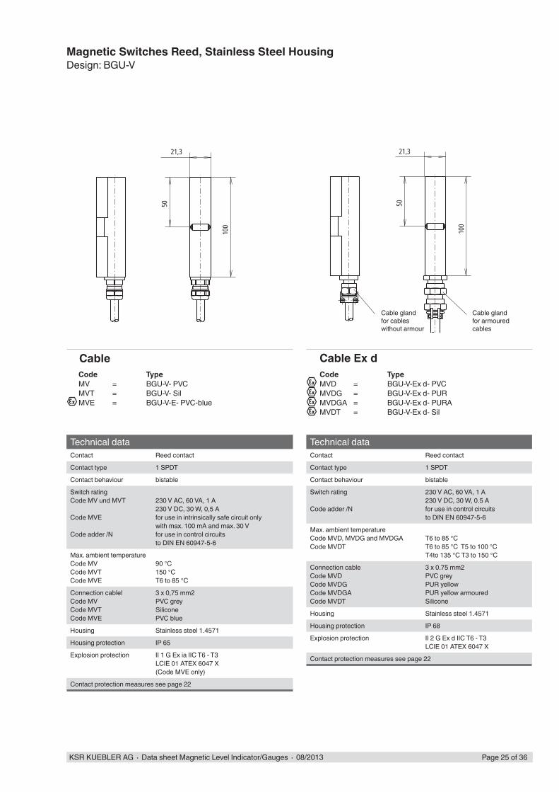
Magnetic Switches Reed, Stainless Steel HousingDesign: BGU-V
Technical dataContact Reed contact
Contact type 1 SPDT
Contact behaviour bistable
Switch ratingCode MV und MVT
Code MVE
Code adder /N
230 V AC, 60 VA, 1 A230 V DC, 30 W, 0,5 Afor use in intrinsically safe circuit onlywith max. 100 mA and max. 30 Vfor use in control circuitsto DIN EN 60947-5-6
Max. ambient temperatureCode MVCode MVTCode MVE
90 °C150 °CT6 to 85 °C
Connection cablelCode MVCode MVTCode MVE
3 x 0,75 mm2PVC greySiliconePVC blue
Housing Stainless steel 1.4571
Housing protection IP 65
Explosion protection II 1 G Ex ia IIC T6 - T3LCIE 01 ATEX 6047 X (Code MVE only)
Contact protection measures see page 22
Code TypeMV = BGU-V- PVCMVT = BGU-V- SilMVE = BGU-V-E- PVC-blue
Technical dataContact Reed contact
Contact type 1 SPDT
Contact behaviour bistable
Switch rating
Code adder /N
230 V AC, 60 VA, 1 A230 V DC, 30 W, 0.5 Afor use in control circuitsto DIN EN 60947-5-6
Max. ambient temperatureCode MVD, MVDG and MVDGACode MVDT
T6 to 85 °CT6 to 85 °C T5 to 100 °CT4to 135 °C T3 to 150 °C
Connection cableCode MVDCode MVDGCode MVDGACode MVDT
3 x 0.75 mm2PVC greyPUR yellowPUR yellow armouredSilicone
Housing Stainless steel 1.4571
Housing protection IP 68
Explosion protection II 2 G Ex d IIC T6 - T3LCIE 01 ATEX 6047 X
Contact protection measures see page 22
Code TypeMVD = BGU-V-Ex d- PVCMVDG = BGU-V-Ex d- PURMVDGA = BGU-V-Ex d- PURAMVDT = BGU-V-Ex d- Sil
Cable glandfor cableswithout armour
Cable gland for armouredcables
Cable Cable Ex d

M20x1,580
115
7463
122
75
M20x1,5
111
94
106
85
M20x1,5
Page 26 of 36 KSR KUEBLER AG ∙ Data sheet Magnetic Level Indicator/Gauges ∙ 08/2013
Magnetic Switches, Reed High-TemperatureDesign: BGU-AHT, Aluminium housing
Technical DataContact Reed contact
Contact type 1 SPDT
Contact behaviour bistable
Switch rating
adder /N
230 V AC, 60 VA, 1 A230 V DC, 30 W, 0.5 Afor use in control circuitsto DIN EN 60947-5-6
Max. ambient temperature 380 °C
Housing Aluminium
Housing protection IP 65
Contact protection measures see page 22
Code TypeMHT = BGU-AHT
High Temperature
Mounting with tightening straps
Mounting on MRA with T-slot
Technical DataContact Reed contact
Contact type 1 SPDT
Contact behaviour bistable
Switch rating
adder /N
230 V AC, 60 VA, 1 A230 V DC, 30 W, 0.5 Afor use in control circuitsto DIN EN 60947-5-6
Max. ambient temperature 380 °C
Housing Stainless-steel
Housing protection IP 67
Contact protection measures see page 22
Code TypeMVHT = BGU-VHT
High Temperature
Mounting with tightening straps
Design: BGU-VHT, stainless-steel housing
115
6374
M20x1,5
122
75
M20x1,5
111
115
6374
M20x1,5
122
75
M20x1,5
111
KSR KUEBLER AG ∙ Data sheet Magnetic Level Indicator/Gauges ∙ 08/2013 Page 27 of 36
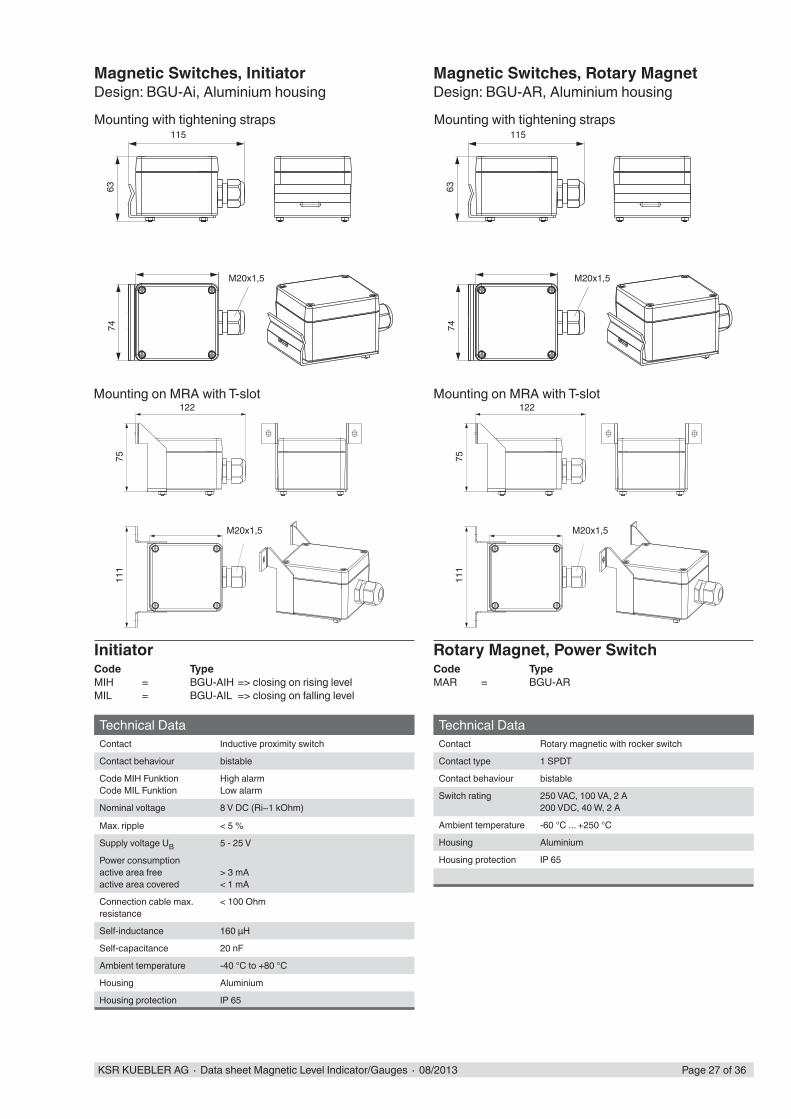
Technical DataContact Inductive proximity switch
Contact behaviour bistable
Code MIH FunktionCode MIL Funktion
High alarmLow alarm
Nominal voltage 8 V DC (Ri~1 kOhm)
Max. ripple < 5 %
Supply voltage UB 5 - 25 V
Power consumptionactive area freeactive area covered
> 3 mA< 1 mA
Connection cable max.resistance
< 100 Ohm
Self-inductance 160 μH
Self-capacitance 20 nF
Ambient temperature -40 °C to +80 °C
Housing Aluminium
Housing protection IP 65
Code TypeMIH = BGU-AIH => closing on rising levelMIL = BGU-AIL => closing on falling level
Initiator
Technical DataContact Rotary magnetic with rocker switch
Contact type 1 SPDT
Contact behaviour bistable
Switch rating 250 VAC, 100 VA, 2 A200 VDC, 40 W, 2 A
Ambient temperature -60 °C ... +250 °C
Housing Aluminium
Housing protection IP 65
Magnetic Switches, InitiatorDesign: BGU-Ai, Aluminium housing
Rotary Magnet, Power Switch
Magnetic Switches, Rotary MagnetDesign: BGU-AR, Aluminium housing
Mounting with tightening straps
Mounting on MRA with T-slot
Mounting with tightening straps
Mounting on MRA with T-slot
Code TypeMAR = BGU-AR
151
144
87
151
144
87
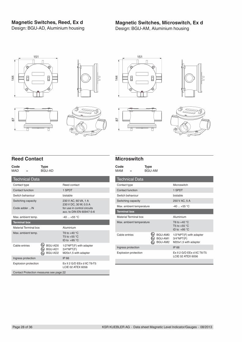
Page 28 of 36 KSR KUEBLER AG ∙ Data sheet Magnetic Level Indicator/Gauges ∙ 08/2013
Technical DataContact type Reed contact
Contact function 1 SPDT
Switch behaviour bistable
Switching capacity
Code adder .../N
230 V AC, 60 VA, 1 A230 V DC, 30 W, 0.5 Afor use in control circuitsacc. to DIN EN 60947-5-6
Max. ambient temp. -40 ... +55 °C
Terminal box
Material Terminal box Aluminium
Max. ambient temp. T6 to +40 °CT5 to +55 °CtD to +95 °C
Cable entries BGU-AD0BGU-AD1BGU-AD2
1/2“NPT(F) with adapter3/4“NPT(F)M20x1,5 with adapter
Ingress protection IP 66
Explosion protection Ex II 2 G/D EEx d IIC T6-T5LCIE 02 ATEX 6056
Contact Protection measures see page 22
Reed Contact
Technical DataContact type Microswitch
Contact function 1 SPDT
Switch behaviour bistable
Switching capacity 250 V AC, 5 A
Max. ambient temperature -40 ... +55 °C
Terminal box
Material Terminal box Aluminium
Max. ambient temperature T6 to +40 °CT5 to +55 °CtD to +95 °C
Cable entries BGU-AM0BGU-AM1BGU-AM2
1/2“NPT(F) with adapter3/4“NPT(F)M20x1,5 with adapter
Ingress protection IP 66
Explosion protection Ex II 2 G/D EEx d IIC T6-T5LCIE 02 ATEX 6056
Microswitch
Magnetic Switches, Reed, Ex dDesign: BGU-AD, Aluminium housing
Magnetic Switches, Microswitch, Ex dDesign: BGU-AM, Aluminium housing
Code TypeMAD = BGU-AD
Code TypeMAM = BGU-AM
KSR KUEBLER AG ∙ Data sheet Magnetic Level Indicator/Gauges ∙ 08/2013 Page 29 of 36
Type codeCode
3 Basic typeMG Level sensor
3.1 Electrical connection (terminal box)... A Aluminium - top APL Polyester - top (Ex-design) AVG Stainless steel - top with digital display
AU Aluminium - bottom APLU Polyester - bottom (Ex-design) AVGU Stainless steel - bottom with digital display
AP Polyester - top AV4 Edelstahl - topAPU Polyester - bottom AV4U Edelstahl - bottom3.2 1st key Material sensor tube 2nd key Contact separation Optional code
.../... V Stainless steel K18 18 mm contact separation 5 / 10 / 15 mm onlyK15 15 mm /HT.. High temperature +120 °C ... +200 °CK10 10 mm /TT.. Low temperature -10 °C ... -80 °CK5 5 mm
3.3 (Option) Head mounted transmitter in terminal box... TS 2-wire Standard
TE 2-wire Ex i TLH 2-wire HART® with LCD displayTLEH 2-wire Ex i HART® with LCD displayT32 2-wire Ex i HART® programmableT53P Ex i Profi bus PA programmableT53F Foundation Fieldbus programmable
3.4 1st key Sensor tube length 2nd key Measuring range 3rd key Sensor tube dimensions.../.../... L... Length in mm M... Range in mm 14 OD Ø 14 mm
3.5 Optional code... Ex Ex Control circuit EEx ib IIC or EEx ia IIC, resistance of measuring chain: 3.2 kOhm ... 50 kOhm
Basic type Electricalconnection
Material Sensor tubeContact separation
OptionHead-mountedtransmitter
Sensor tube-lengthMeasuring rangeSensor tube-dimensions
Optional code
Code 3 - 3.1 - 3.2 - 3.3 / 3.4 - 3.5
MG - AU - VK10 - TE / L1650 / M1500 / 14 - Ex
Ordering example
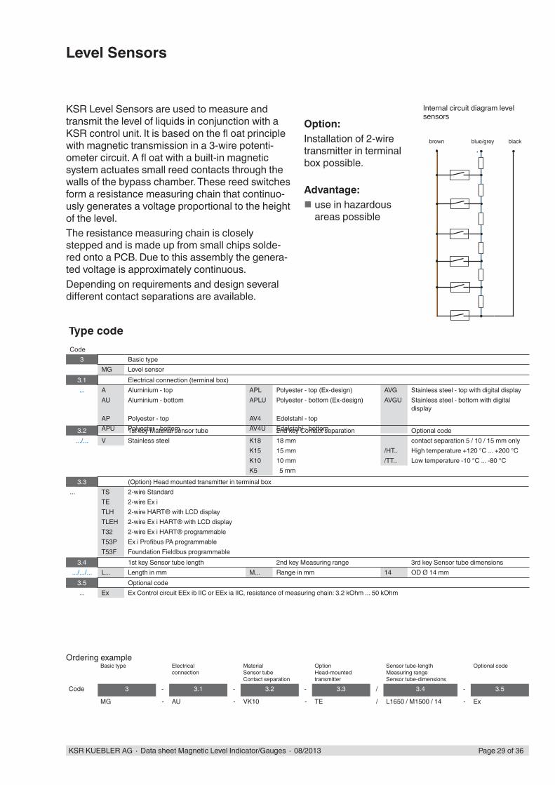
Level Sensors
KSR Level Sensors are used to measure and transmit the level of liquids in conjunction with a KSR control unit. It is based on the fl oat principle with magnetic transmission in a 3-wire potenti-ometer circuit. A fl oat with a built-in magnetic system actuates small reed contacts through the walls of the bypass chamber. These reed switches form a resistance measuring chain that continuo-usly generates a voltage proportional to the height of the level. The resistance measuring chain is closely stepped and is made up from small chips solde-red onto a PCB. Due to this assembly the genera-ted voltage is approximately continuous.Depending on requirements and design several diff erent contact separations are available.
Option:Installation of 2-wire transmitter in terminal box possible.
Advantage: use in hazardous areas possible
Internal circuit diagram levelsensors
brown blue/grey black
~92
22,5
100
0%
M=…
100%
Ø14
50
80
75
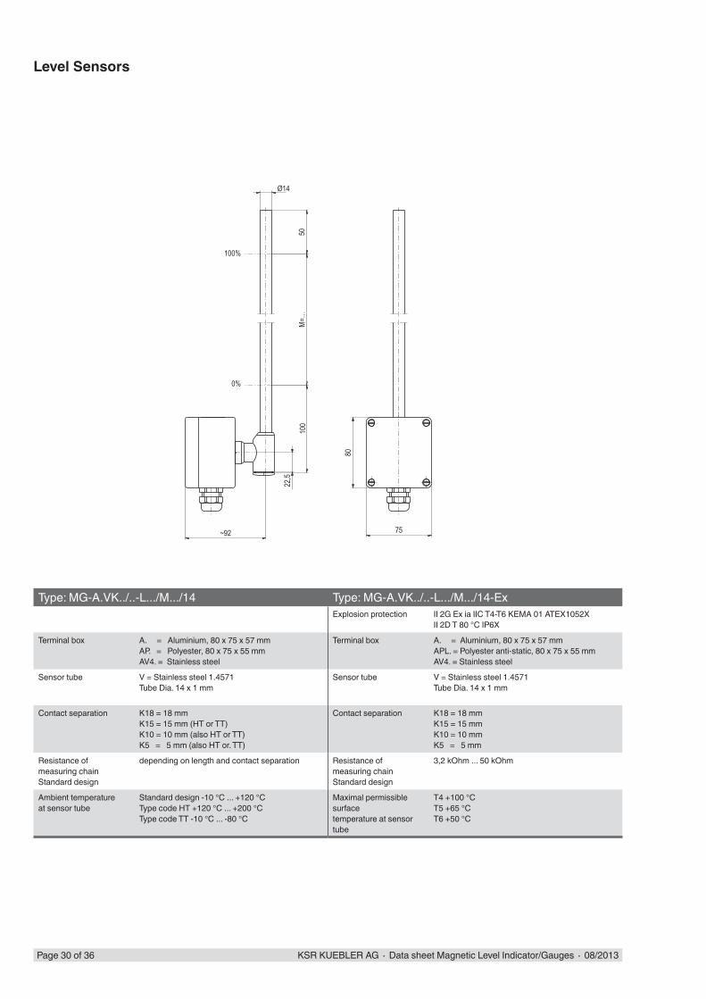
Page 30 of 36 KSR KUEBLER AG ∙ Data sheet Magnetic Level Indicator/Gauges ∙ 08/2013
Type: MG-A.VK../..-L.../M.../14 Type: MG-A.VK../..-L.../M.../14-ExExplosion protection II 2G Ex ia IIC T4-T6 KEMA 01 ATEX1052X
II 2D T 80 °C IP6X
Terminal box A. = Aluminium, 80 x 75 x 57 mmAP. = Polyester, 80 x 75 x 55 mmAV4. = Stainless steel
Terminal box A. = Aluminium, 80 x 75 x 57 mmAPL. = Polyester anti-static, 80 x 75 x 55 mmAV4. = Stainless steel
Sensor tube V = Stainless steel 1.4571Tube Dia. 14 x 1 mm
Sensor tube V = Stainless steel 1.4571Tube Dia. 14 x 1 mm
Contact separation K18 = 18 mmK15 = 15 mm (HT or TT)K10 = 10 mm (also HT or TT)K5 = 5 mm (also HT or. TT)
Contact separation K18 = 18 mmK15 = 15 mmK10 = 10 mmK5 = 5 mm
Resistance ofmeasuring chainStandard design
depending on length and contact separation Resistance ofmeasuring chainStandard design
3,2 kOhm ... 50 kOhm
Ambient temperatureat sensor tube
Standard design -10 °C ... +120 °CType code HT +120 °C ... +200 °CType code TT -10 °C ... -80 °C
Maximal permissible surfacetemperature at sensor tube
T4 +100 °CT5 +65 °CT6 +50 °C
Level Sensors

Ø 70~113
~93 75
80
~125
Ø 70
77
KSR KUEBLER AG ∙ Data sheet Magnetic Level Indicator/Gauges ∙ 08/2013 Page 31 of 36
Level SensorsHousing options
Type code A. = Aluminium 80 x 75 x 57 mmType code AP. = Polyester 80 x 75 x 55 mmType code APL. = Polyester 80 x 75 x 55 mm, anti-static
Typcode AVG = Stainless steel with digital display
Typcode AV4 = Stainless steel
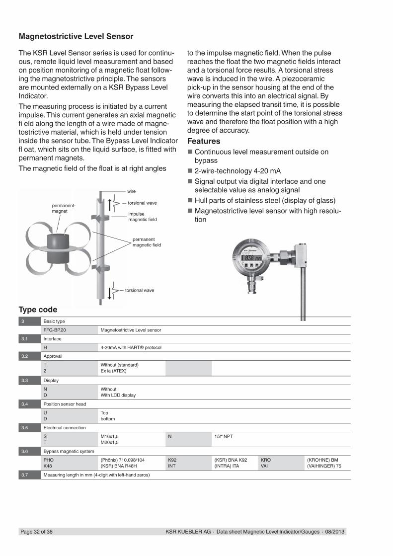
Page 32 of 36 KSR KUEBLER AG ∙ Data sheet Magnetic Level Indicator/Gauges ∙ 08/2013
The KSR Level Sensor series is used for continu-ous, remote liquid level measurement and based on position monitoring of a magnetic fl oat follow-ing the magnetostrictive principle. The sensors are mounted externally on a KSR Bypass Level Indicator.The measuring process is initiated by a current impulse. This current generates an axial magnetic fi eld along the length of a wire made of magne-tostrictive material, which is held under tension inside the sensor tube. The Bypass Level Indicator fl oat, which sits on the liquid surface, is fi tted with permanent magnets.The magnetic fi eld of the fl oat is at right angles
wire
torsional wave
impulsemagnetic fi eld
torsional wave
permanentmagnetic fi eld
permanent-magnet
Magnetostrictive Level Sensor
to the impulse magnetic fi eld. When the pulse reaches the fl oat the two magnetic fi elds interact and a torsional force results. A torsional stress wave is induced in the wire. A piezoceramic pick-up in the sensor housing at the end of the wire converts this into an electrical signal. By measuring the elapsed transit time, it is possible to determine the start point of the torsional stress wave and therefore the fl oat position with a high degree of accuracy.Features
Continuous level measurement outside on bypass
2-wire-technology 4-20 mA Signal output via digital interface and one selectable value as analog signal
Hull parts of stainless steel (display of glass) Magnetostrictive level sensor with high resolu-tion
3 Basic type
FFG-BP.20 Magnetostrictive Level sensor
3.1 Interface
H 4-20mA with HART® protocol
3.2 Approval
12
Without (standard)Ex ia (ATEX)
3.3 Display
ND
WithoutWith LCD display
3.4 Position sensor head
UD
Topbottom
3.5 Electrical connection
ST
M16x1,5M20x1,5
N 1/2“ NPT
3.6 Bypass magnetic system
PHOK48
(Phönix) 710.098/104(KSR) BNA R48H
K92INT
(KSR) BNA K92(INTRA) ITA
KROVAI
(KROHNE) BM(VAIHINGER) 75
3.7 Measuring length in mm (4-digit with left-hand zeros)
Type code
KSR KUEBLER AG ∙ Data sheet Magnetic Level Indicator/Gauges ∙ 08/2013 Page 33 of 36
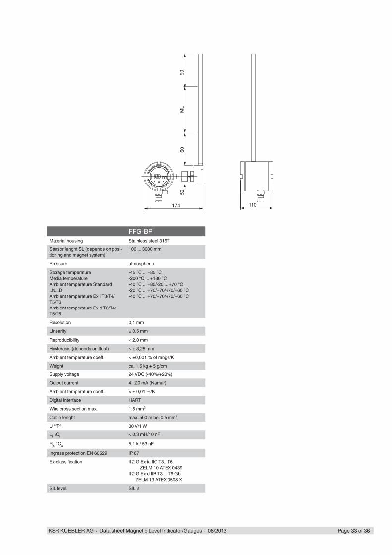
FFG-BPMaterial housing Stainless steel 316Ti
Sensor lenght SL (depends on posi-tioning and magnet system)
100 ... 3000 mm
Pressure atmospheric
Storage temperatureMedia temperatureAmbient temperature Standard ..N/..DAmbient temperature Ex i T3/T4/T5/T6Ambient temperature Ex d T3/T4/T5/T6
-45 °C ... +85 °C-200 °C ... +180 °C-40 °C ... +85/-20 ... +70 °C-20 °C ... +70/+70/+70/+60 °C-40 °C ... +70/+70/+70/+60 °C
Resolution 0,1 mm
Linearity ± 0,5 mm
Reproducibility < 2,0 mm
Hysteresis (depends on fl oat) ≤ ± 3,25 mm
Ambient temperature coeff . < ±0,001 % of range/K
Weight ca. 1,5 kg + 5 g/cm
Supply voltage 24 VDC (-40%/+20%)
Output current 4...20 mA (Namur)
Ambient temperature coeff . < ± 0,01 %/K
Digital Interface HART
Wire cross section max. 1,5 mm²
Cable lenght max. 500 m bei 0,5 mm²
U °/P° 30 V/1 W
Li /Ci < 0,3 mH/10 nF
Rx / Cx 5,1 k / 53 nF
Ingress protection EN 60529 IP 67
Ex-classifi cation II 2 G Ex ia IIC T3...T6 ZELM 10 ATEX 0439II 2 G Ex d IIB T3 ... T6 Gb ZELM 13 ATEX 0508 X
SIL level: SIL 2
Page 34 of 36 KSR KUEBLER AG ∙ Data sheet Magnetic Level Indicator/Gauges ∙ 08/2013
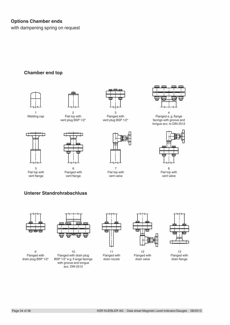
Options Chamber endswith dampening spring on request
Chamber end top
1Welding cap
Unterer Standrohrabschluss
2Flat top with
vent plug BSP 1/2“
3Flanged with
vent plug BSP 1/2“
4Flanged e. g. fl ange
facings with groove andtongue acc. to DIN 2512
5Flat top withvent fl ange
6Flanged withvent fl ange
7Flat top withvent valve
8Flat top withvent valve
9Flanged with
drain plug BSP 1/2“
10Flanged with drain plug
BSP 1/2“ e.g. fl ange facingswith groove and tongue
acc. DIN 2512
11Flanged withdrain nozzle
12Flanged withdrain valve
13Flanged withdrain fl ange
KSR KUEBLER AG ∙ Data sheet Magnetic Level Indicator/Gauges ∙ 08/2013 Page 35 of 36
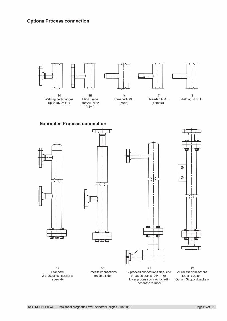
Options Process connection
Examples Process connection
14Welding neck fl anges
up to DN 25 (1“)
15Blind fl ange
above DN 32 (11/4“)
16Threaded GN...
(Male)
17Threaded GM...
(Female)
18Welding stub S...
19Standard
2 process connectionsside-side
20Process connections
top and side
212 process connections side-side
threaded acc. to DIN 11851lower process connection with
eccentric reducer
222 Process connections
top and bottomOption: Support brackets

KSR KUEBLER Niveau-Messtechnik AGHeinrich-Kuebler-Platz 169439 ZwingenbergTelefon (+49) 6263 87-0Fax (+49) 6263 8799E-Mail [email protected]
A division of the WIKA Group
1124
99
KSR KUEBLER AG ∙ Data sheet Magnetic Level Indicator/Gauges ∙ 08/2013Page 36 von 36
Modifi cations may take place and materials specifi ed may be replaced by others without prior notice.Specifi cations and dimensions given in this leafl et represent the state of engineering at the time of printing.
Related Documents