Welcome message from author
This document is posted to help you gain knowledge. Please leave a comment to let me know what you think about it! Share it to your friends and learn new things together.
Transcript

���������� ������������������������������������������
������������������������������������������������������������������������������������������������� �������������������������������������������������������������� ��������������������������������������������
Magdalena Ridge Observatory Interferometer Automated Alignment System
A.V. Shtromberg*a, C.A. Jurgensona, K.M. McCorda, A.M Olivaresa, H.N. Bloemharda, F.G.
Santoroa, D.F. Buscherb, C.A. Haniffb, J.S. Youngb, N.C. Torresa, A.R. Farrisa aMagdalena Ridge Observatory, New Mexico Institute of Mining and Technology, 801 Leroy
Place, Socorro, NM, 87801-4681; bUniversity of Cambridge, Dept. of Physics, Cavendish Laboratory, JJ Thomson Avenue,
Cambridge, CB3 OHE, UK
ABSTRACT
Here is presented the current outline and progress of MROI’s automated alignment system design. Depending on the location of each of MROI’s unit telescopes (UT), light can travel distances ranging from 460 to 660 meters via several reflections that redirect the beam’s path through the beam relay system (BRS), delay line system (DLS), beam compressing telescope (BCR), switchyards and finally to the beam combiners (BC). All of these sub-systems comprise three major optical axes of the MROI which must be coaligned on a nightly basis by the AAS. The AAS consists of four subsystems: the primary fiducial—for beam injection, the UT tilt and shear measurement components (TASM), the BC TASM components, and the secondary fiducial—for quick alignment checks. All of these subsystems contribute to the unique design of the AAS which will allow for simultaneous measurements from the visible to the near-IR wavelengths, full automation, the capability to perform optical path difference (OPD) alignment and spectral calibration, making it cost effective and saving on realty in the beam combining area (BCA). The AAS is nearing completion and assembly of the various subsystems is expected to commence soon. The latest results on all of the following are reviewed here. Keywords: MROI, interferometry, automated alignment system, tilt and shear.
1. INTRODUCTION
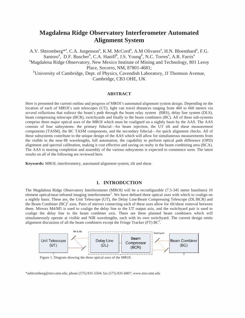
The Magdalena Ridge Observatory Interferometer (MROI) will be a reconfigurable (7.5-345 meter baselines) 10 element optical/near-infrared imaging interferometer1. We have defined three optical axes with which to coalign on a nightly basis. These are, the Unit Telescope (UT), the Delay Line/Beam Compressing Telescope (DL/BCR) and the Beam Combiner (BC)2 axes. Pairs of mirrors connecting each of these axes allow for tilt/shear removal between them. Mirrors M4/M5 is used to coalign the delay line to the UT output axis, and the switchyard pair is used to coalign the delay line to the beam combiner axis. There are three planned beam combiners which will simultaneously operate at visible and NIR wavelengths, each with its own switchyard. The current design omits alignment discussion of all the beam combiners except the Fringe Tracker (FT) BC3.
Figure 1. Diagram showing the three optical axes of the MROI.
*[email protected]; phone (575) 835-5504; fax (575) 835-6807; www.mro.nmt.edu

The AAS will inject a reference beam (Figure 2) into the interferometer upstream and downstream that accommodates the wavelengths (Table 1) that MROI will operate in—due to the optimized optics for the specific wavelengths. Downstream, the 95mm beam exiting the UT, enters the BRS (in vacuum), gets directed into the DLS and finally exits into the inner BCA. It then gets compressed (7.308x) to a 13 mm diameter beam by the BCR before encountering the switchyard and the BC table.
Table 1. Table showing the operating wavelengths and the corresponding beam combiners for the interferometer.
Wavelength, �, (�m) Bandpass Beam Combiner
0.656, 0.650-1.0 H. Visible
1.1 – 1.39 J IR Science
1.5 – 1.8 H IR Science, FT
2.0 – 2.4 K IR Science
1.99 – 2.31 Ks FT
Figure 2. Optical layout of beam path from UT to BCA with AAS reference beam injected upstream and downstream
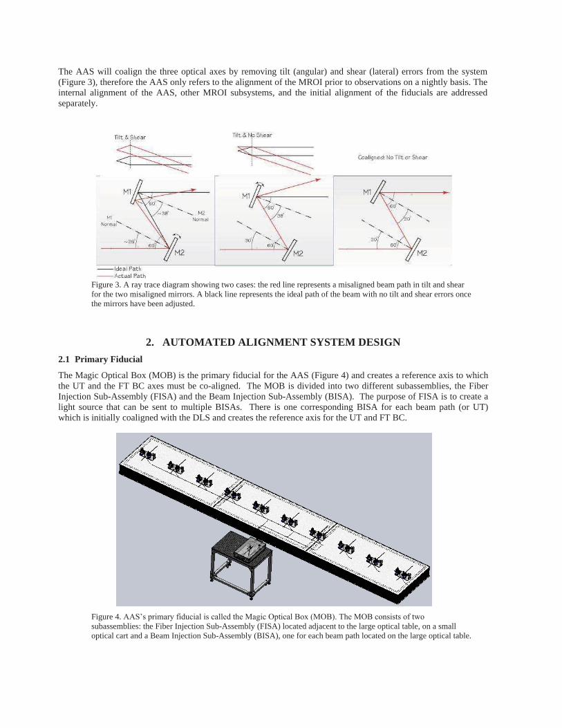
The AAS will coalign the three optical axes by removing tilt (angular) and shear (lateral) errors from the system (Figure 3), therefore the AAS only refers to the alignment of the MROI prior to observations on a nightly basis. The internal alignment of the AAS, other MROI subsystems, and the initial alignment of the fiducials are addressed separately.
Figure 3. A ray trace diagram showing two cases: the red line represents a misaligned beam path in tilt and shear for the two misaligned mirrors. A black line represents the ideal path of the beam with no tilt and shear errors once the mirrors have been adjusted.
2. AUTOMATED ALIGNMENT SYSTEM DESIGN
2.1 Primary Fiducial
The Magic Optical Box (MOB) is the primary fiducial for the AAS (Figure 4) and creates a reference axis to which the UT and the FT BC axes must be co-aligned. The MOB is divided into two different subassemblies, the Fiber Injection Sub-Assembly (FISA) and the Beam Injection Sub-Assembly (BISA). The purpose of FISA is to create a light source that can be sent to multiple BISAs. There is one corresponding BISA for each beam path (or UT) which is initially coaligned with the DLS and creates the reference axis for the UT and FT BC.
Figure 4. AAS’s primary fiducial is called the Magic Optical Box (MOB). The MOB consists of two
subassemblies: the Fiber Injection Sub-Assembly (FISA) located adjacent to the large optical table, on a small optical cart and a Beam Injection Sub-Assembly (BISA), one for each beam path located on the large optical table.

2.1.1 Fiber Injection Sub-Assembly
The FISA is located on an optical cart adjacent to the large AAS optical table in the inner BCA. During operations it will always have a cover on (Figure 5a) to prevent dust and damage. FISA contains two light sources: a white light source and a laser diode (�=635nm) (Figure 5b).
The white light bulb is placed into a cylindrical housing—highly polished on the inside to maximize intensity output (Figure 5b). Temperature control is a crucial issue in the inner BCA; therefore heat sync is placed on top of the bulb housing to dissipate heat to the outer BCA. Rays unvignetted by the focusing lens following the white light will then be focused onto a pinhole. Following the pinhole, the light is collimated by an off-axis parabolic mirror (OAP). The beam is then split 50/50 by a custom coated beamsplitter, and the two halves are injected into single mode fibers. The current design accommodates a two telescope configuration. For more telescopes the beam will be focused and then split into a fiber bundlewith multiple fibers located at the focal point of the OAPs.
Figure 5. The MOB FISA splits the white light and the laser diode beams into multiple fibers for individual BISAs.
2.1.2 Beam Injection Sub-Assembly
At the output of BISA (Figure 6), light leaves the fiber and is collimated by another OAP before being sent into the interferometer beam train. Following the OAP, a beamsplitter serves the purpose of diverting the beams to the UTs and the BCs. A CCR following the beamsplitter reflects the transmitted beam back to the beamsplitter to reflect it in the opposite direction.. The beamsplitter will have a custom 50:50 reflection/transmission coating on one side, and an AR coating on the other. These coatings are functional from the visible to NIR wavelengths.
The beamsplitter will be placed in a tip-tilt gimbal mount and secured in a “V-T” base mount, which will be placed
on an automated translation slide that is bolted to the base. The 75mm travel slide will allow the beamsplitter to move in and out of the beams’ path for alignment/observation modes. The tip-tilt actuation and the translation slide will also provide the means for aligning the primary fiducial to the DL in tilt and shear. The CCR will be positioned within its housing and mounted to a custom machined base that will be placed on a one time x-y adjustment slide.
a b
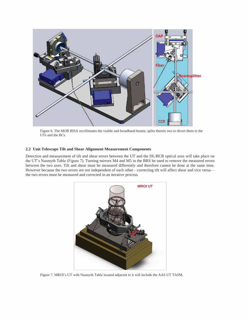
Figure 6. The MOB BISA recollimates the visible and broadband beams, splits themin two to divert them to the UTs and the BCs.
2.2 Unit Telescope Tilt and Shear Alignment Measurement Components
Detection and measurement of tilt and shear errors between the UT and the DL/BCR optical axes will take place on the UT’s Nasmyth Table (Figure 7). Turning mirrors M4 and M5 in the BRS be used to remove the measured errors between the two axes. Tilt and shear must be measured differently and therefore cannot be done at the same time. However because the two errors are not independent of each other—correcting tilt will affect shear and vice versa—the two errors must be measured and corrected in an iterative process.
Figure 7. MROI’s UT with Nasmyth Table located adjacent to it will include the AAS UT TASM.
MROI UT

Measuring the shear error between the UT optical axis and DL/BCR axis, requires imaging the pupil of the telescope. To do this, a ring of 4 equally spaced LEDs located around the primary mirror, M1 will illum inate M2 and traverse to the Nasmyth Table where it is reflected by a beamsplitter to a powered lens which reimages the LEDs onto a detector. The position of the intersection of the four LED images is then compared to the centroid position of the primary fiducial beam.
There are two subassemblies that make up the shear measurement hardware (Figure 8a), subassembly 1: the beamsplitter on a slide and a corner cube retroreflector (CCR), and subassembly 2: the focusing optic and the shear detector; with each subassembly on separate mounting plates. The MOB laser diode enters the Nasmyth table upstream after reflecting from M4 (Figure 8a). At subassembly 1 it encounters a beamsplitter, which slides in place for shear measurements, splitting the energy. The reflected—the transmitted is ignored—portion is retroreflected by a CCR and is transmitted through the beamsplitter to subassembly 2; focused by a lens onto the shear detector. The four UT LEDs are also turned on and are reflected by the beamsplitter from subassembly 1. The four beams make their way to subassembly 2 and onto the shear detector. The focusing optic assembly will be on a translation stage for focus adjustment.
Figure 8. Shear (a) and tilt (b) hardware at the UT located on the Nasmyth Table.
Tilt measurements are made using the Fast Tip-Tilt (FTT) hardware (Figure 8b) which includes the FTT detector, plus an extra CCR. In this case, the M1 LEDs are not used, but rather M3 is put into retro-reflection mode. Upon arriving at the Nasmyth Table, a portion of the primary fiducial light is split off by the tip-tilt dichroic which directs the beam to the FTT CCD (via a CCR and the focusing OAP); this spot represents the DL/BCR axis. A portion of the beam is then transmitted to, and retroreflected by M3 back to the FTT CCD. The outer axis of the UT is then rotated to see if there is a displacement of the spot from M3’s reflected light with respect to the spot that represents
the DL/BCR axis. If the retroreflected spot moves relative to the other, then there is tilt or angular error present. 2.3 Fringe Tracker Beam Combiner Tilt and Shear Alignment Components
The interferometer’s will ultimately have three beam combining instruments: the visible BC, the IR science BC, and the FT BC. All three instruments will have their own optical axis to which the DL/BCR axis must be aligned to. The
AAS Shear Hardware AAS Tilt Configuration
a b

IR science BC design is currently in the conceptual phase, but not mature enough to discuss in this paper. Therefore only the FT BC alignment scheme is discussed here.
Figure 9. Fringe tracker beam combiner with its corresponding switchyard mirrors (used to make tilt and shear corrections) and the FT TASM components (circled in red) at one of the BC’s output.
Similar to the Nasmyth Table design, the beams at the FT table are diverted from their path to tilt and shear detectors via a set of pop-up flipper mirrors (Figure 10). The FT BC will combine light for 10 telescopes and have 9 combined output beams. There will be a total of 9 flip mirrors which are located at combiner output 1. The arrangement of the flip mirrors only allows one mirror to be flipped in at any time during the alignment process. When the FT is in operations the flip mirrors are rotated into the 'up' position, and the FT output beams are injected into the spectrograph. Inspection of Figures 10 and 11 shows that the MOB white light beam reflected off the flip mirror will pass into a beamsplitter. The reflected beam will enter a beam reducer which will compress the beam 3x for shear measurements. The transmitted beam will pass through a focusing lens and on to a detector for tilt measurements. The beam compressing optical assembly is necessary to reduce the size of the beam to accommodate the detector array size (Figure 11).
Figure 10. Pop up flipper mirrors located at one of the beam combination outputs diverts the white light beam to the TASM components.

Figure 11. FT BC TASM assembly.
Figure 12. (a) Fringe Tracker Beam Combiner optical schematic. Tilt and shear measurements take place at combiner output 1. (b) Corresponding UT locations BC output 1.
b
a
Alignment of the FT BC must be done is a very particular order due to its architecture (see Figure 12a and b). For inputs corresponding to telescopes in a given arm in the interferometer, the centroid of light being injected into W0 (vertex telescope) input of the combiner is first measured and recorded. Light from a '1' telescope (N1, S1, W1) is then input into the combiner where it forms fringes with the vertex telescope, and its centroid is measured and recorded. The switchyard mirrors for '1' are then adjusted to remove the tilt and shear errors between it and W0. This process is repeated for all '1' and '2' (N2, S2, W2,) telescope combinations, where the '2' switchyard is used to remove errors between it and '1'. And finally, the '2'/'3' telescope combinations, where the '3' (N3, S3, W3) switchyard is used to remove errors between it and the '2' telescopes. 2.4 Secondary Fiducial
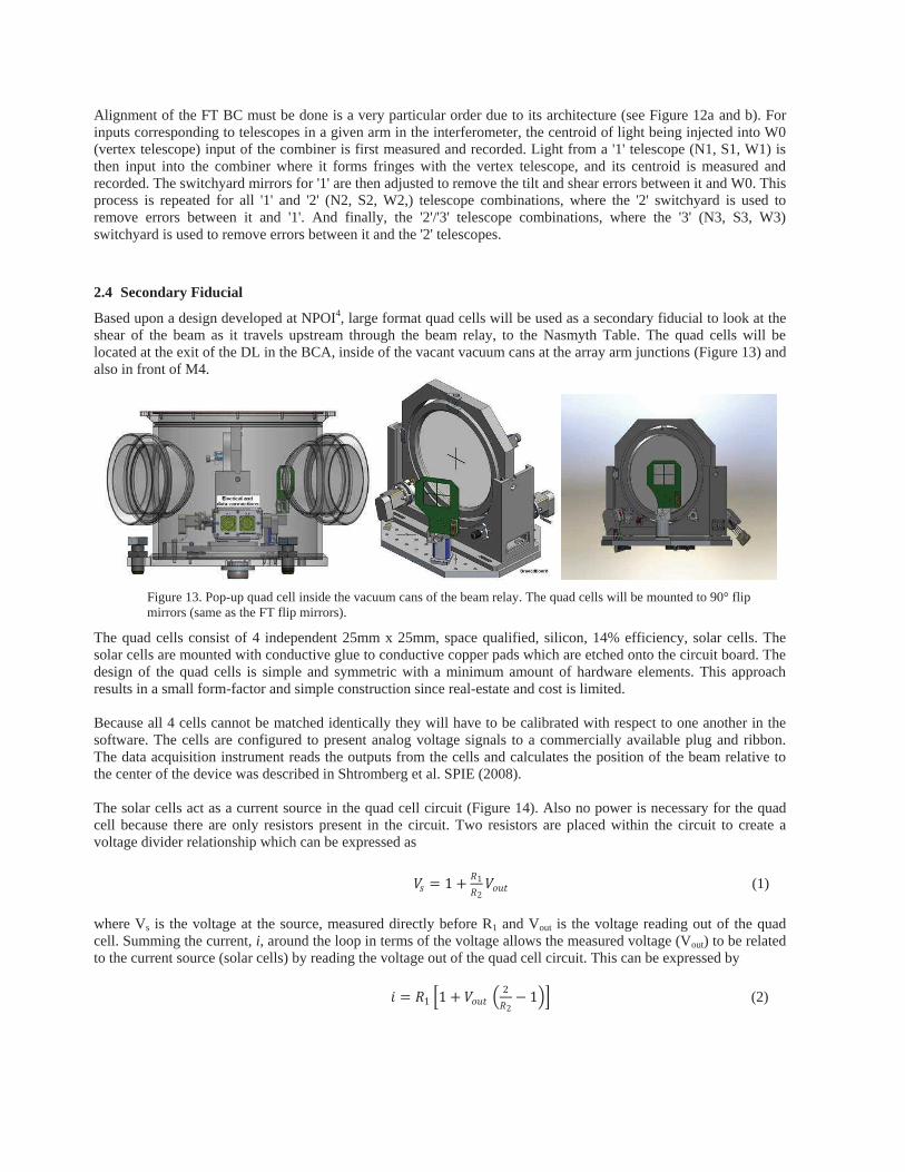
Based upon a design developed at NPOI4, large format quad cells will be used as a secondary fiducial to look at the shear of the beam as it travels upstream through the beam relay, to the Nasmyth Table. The quad cells will be located at the exit of the DL in the BCA, inside of the vacant vacuum cans at the array arm junctions (Figure 13) and also in front of M4.
Figure 13. Pop-up quad cell inside the vacuum cans of the beam relay. The quad cells will be mounted to 90° flip mirrors (same as the FT flip mirrors).
The quad cells consist of 4 independent 25mm x 25mm, space qualified, silicon, 14% efficiency, solar cells. The solar cells are mounted with conductive glue to conductive copper pads which are etched onto the circuit board. The design of the quad cells is simple and symmetric with a minimum amount of hardware elements. This approach results in a small form-factor and simple construction since real-estate and cost is limited. Because all 4 cells cannot be matched identically they will have to be calibrated with respect to one another in the software. The cells are configured to present analog voltage signals to a commercially available plug and ribbon. The data acquisition instrument reads the outputs from the cells and calculates the position of the beam relative to the center of the device was described in Shtromberg et al. SPIE (2008). The solar cells act as a current source in the quad cell circuit (Figure 14). Also no power is necessary for the quad cell because there are only resistors present in the circuit. Two resistors are placed within the circuit to create a voltage divider relationship which can be expressed as
�
8O L sE4s
4t
8KQP (1)
where Vs is the voltage at the source, measured directly before R1 and Vout is the voltage reading out of the quad cell. Summing the current, i, around the loop in terms of the voltage allows the measured voltage (Vout) to be related to the current source (solar cells) by reading the voltage out of the quad cell circuit. This can be expressed by
E L 4s BsE 8KQP @ t4t
F sAC (2)
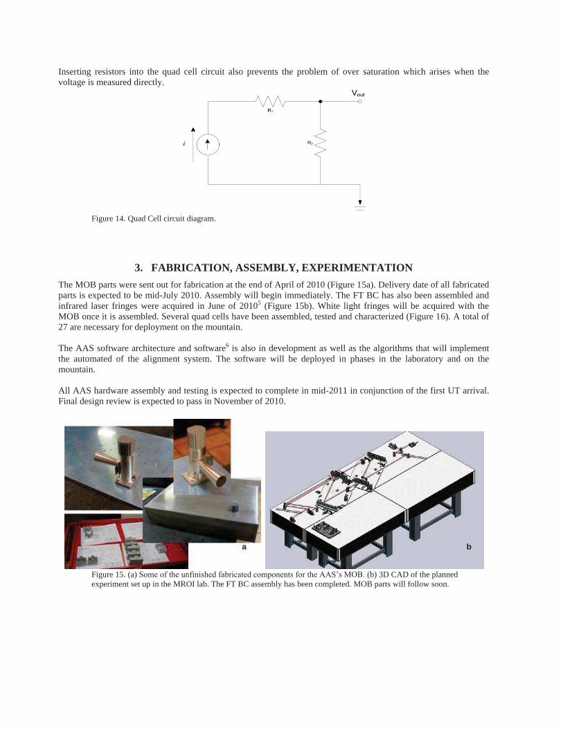
Inserting resistors into the quad cell circuit also prevents the problem of over saturation which arises when the voltage is measured directly.
Figure 14. Quad Cell circuit diagram.
3. FABRICATION, ASSEMBLY, EXPERIMENTATION
The MOB parts were sent out for fabrication at the end of April of 2010 (Figure 15a). Delivery date of all fabricated parts is expected to be mid-July 2010. Assembly will begin immediately. The FT BC has also been assembled and infrared laser fringes were acquired in June of 20105 (Figure 15b). White light fringes will be acquired with the MOB once it is assembled. Several quad cells have been assembled, tested and characterized (Figure 16). A total of 27 are necessary for deployment on the mountain. The AAS software architecture and software6 is also in development as well as the algorithms that will implement the automated of the alignment system. The software will be deployed in phases in the laboratory and on the mountain. All AAS hardware assembly and testing is expected to complete in mid-2011 in conjunction of the first UT arrival. Final design review is expected to pass in November of 2010.
Figure 15. (a) Some of the unfinished fabricated components for the AAS’s MOB. (b) 3D CAD of the planned experiment set up in the MROI lab. The FT BC assembly has been completed. MOB parts will follow soon.
a b
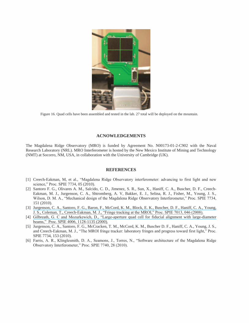
Figure 16. Quad cells have been assembled and tested in the lab. 27 total will be deployed on the mountain.
ACNOWLEDGEMENTS
The Magdalena Ridge Observatory (MRO) is funded by Agreement No. N00173-01-2-C902 with the Naval Research Laboratory (NRL). MRO Interferometer is hosted by the New Mexico Institute of Mining and Technology (NMT) at Socorro, NM, USA, in collaboration with the University of Cambridge (UK).
REFERENCES
[1] Creech-Eakman, M, et al., “Magdalena Ridge Observatory interferometer: advancing to first light and new
science,” Proc. SPIE 7734, 05 (2010). [2] Santoro F. G., Olivares A. M., Salcido, C. D., Jimenez, S. R., Sun, X., Haniff, C. A., Buscher, D. F., Creech-
Eakman, M. J., Jurgenson, C. A., Shtromberg, A. V, Bakker, E. J., Selina, R. J., Fisher, M., Young, J. S., Wilson, D. M. A., “Mechanical design of the Magdalena Ridge Observatory Interferometer,” Proc. SPIE 7734,
151 (2010). [3] Jurgenson, C. A., Santoro, F. G., Baron, F., McCord, K. M., Block, E. K., Buscher, D. F., Haniff, C. A., Young,
J. S., Coleman, T., Creech-Eakman, M. J., “Fringe tracking at the MROI,” Proc. SPIE 7013, 046 (2008). [4] Gilbreath, G. C and Mozurkewich, D., “Large-aperture quad cell for fiducial alignment with large-diameter
beams,” Proc. SPIE 4006, 1128-1135 (2000). [5] Jurgenson, C. A., Santoro, F. G., McCracken, T. M., McCord, K. M., Buscher D. F., Haniff, C. A., Young, J. S.,
and Creech-Eakman, M. J., “The MROI fringe tracker: laboratory fringes and progress toward first light,” Proc.
SPIE 7734, 153 (2010). [6] Farris, A. R., Klinglesmith, D. A., Seamons, J., Torres, N., “Software architecture of the Magdalena Ridge
Observatory Interferometer,” Proc. SPIE 7740, 28 (2010).
Related Documents