MAE 155A Aerospace Engineering Design I Team Firestorm Joshua T. Hu, Project M Brandan York, Chief Eng Michael Basic, Project Aaron Pebley, Project E Proposal #2 Dr. James D. Lang, Project Advisor

MAE 155A Aerospace Engineering Design I
Jan 02, 2016
MAE 155A Aerospace Engineering Design I. Proposal #2 Dr. James D. Lang, Project Advisor. Team Firestorm Joshua T. Hu, Project Manager Brandan York, Chief Engineer Michael Basic, Project Engineer Aaron Pebley, Project Engineer. Outline of Presentation. Scope Design Timeline - PowerPoint PPT Presentation
Welcome message from author
This document is posted to help you gain knowledge. Please leave a comment to let me know what you think about it! Share it to your friends and learn new things together.
Transcript

MAE 155A Aerospace Engineering Design I
Team FirestormJoshua T. Hu, Project Manager
Brandan York, Chief Engineer
Michael Basic, Project Engineer
Aaron Pebley, Project Engineer
Proposal #2
Dr. James D. Lang, Project Advisor

Outline of Presentation
• Scope
• Design Timeline
• Design Factors
• Mission Profile
• Design Approach
• Initial Designs
• Decision Matrix
• Final Design
• Compliance Matrix
• Aerodynamics, Structures, Stability, Subsystems, Supportability, Cost Analysis
• Conclusion and Future Work Needed

Scope
• To develop and recommend an unmanned aerial vehicle (UAV) for the Royal Australian Air Force (RAAF).
• Design must be viable and affordable compared to manned aircraft concepts.
• UAV is to be similar to Joint Strike Fighter (JSF) in performance.

Design Timeline
ID Task Name Start Finish
1 MAE 155A Design Project Thu 1/10/02 Thu 3/14/02
2 RFP #1 Requirements - Individual Thu 1/10/02 Tue 1/29/02
3 RFP #2 Requirements - Team Tue 1/29/02 Thu 3/14/02
4 Formation of Team Tue 1/29/02 Tue 1/29/02
5 Configuration Layouts Wed 1/30/02 Tue 2/5/02
6 Initial Concept Calculations Wed 2/6/02 Thu 2/14/02
7 Design Downselection Fri 2/15/02 Sun 2/17/02
8 Interim Report and Presentation Preparation Mon 2/18/02 Wed 2/20/02
9 Written and Oral Interim Reporting Thu 2/21/02 Thu 2/21/02
10 Detailed Concept Calculations Fri 2/22/02 Mon 3/4/02
11 Cost and Supportability Analysis Tue 3/5/02 Fri 3/8/02
12 Final Report and Presentation Preparation Sat 3/9/02 Wed 3/13/02
13 Final Project Presentation Thu 3/14/02 Thu 3/14/02
2/21
3/14
12/9 12/30 1/20 2/10 3/3 3/24 4/14 5/5December January February March April May
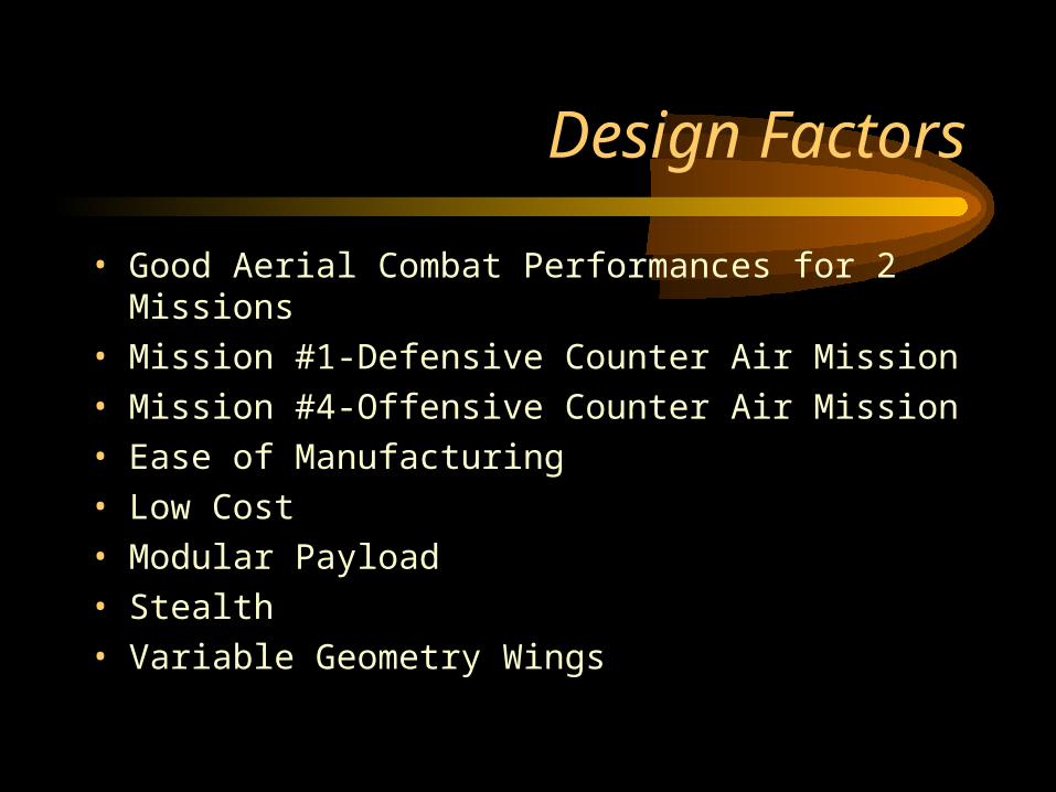
Design Factors
• Good Aerial Combat Performances for 2 Missions
• Mission #1-Defensive Counter Air Mission
• Mission #4-Offensive Counter Air Mission
• Ease of Manufacturing
• Low Cost
• Modular Payload
• Stealth
• Variable Geometry Wings

Mission Profile

Design Approach
• Jetfighter
• Variable Geometry vs. Fixed Wings
• V-Tail vs. Conventional
• Fuselage Geometry
• 2-D Vector Nozzles
• Inlet Styles
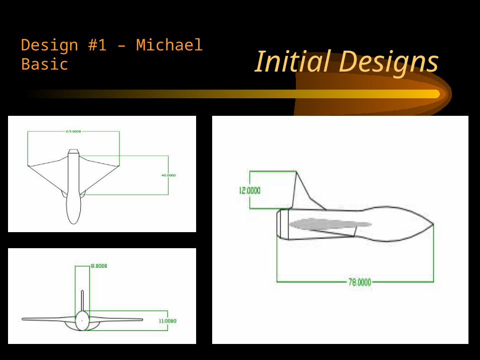
Initial DesignsDesign #1 – Michael Basic
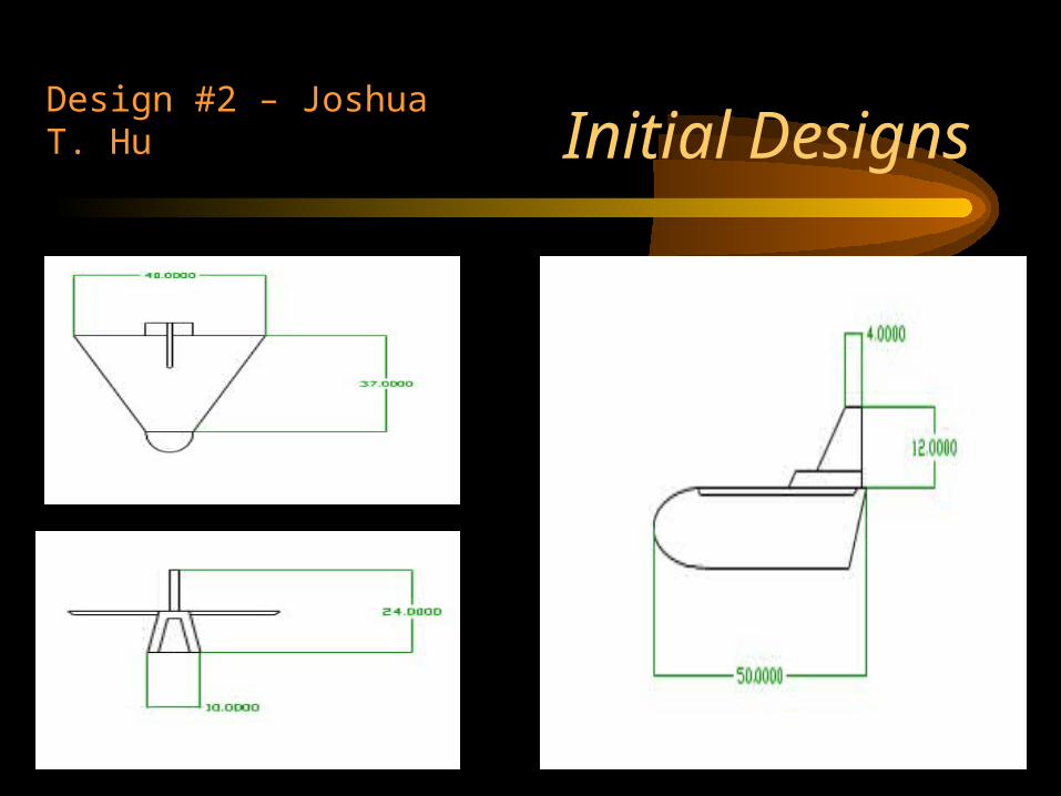
Initial DesignsDesign #2 – Joshua T. Hu

Initial DesignsDesign #3 – Aaron Pebley

Initial DesignsDesign #4 – Brandan York

Initial DesignsDesign #5 – Joshua T. Hu

Initial DesignsDesign #6 – Brandan York
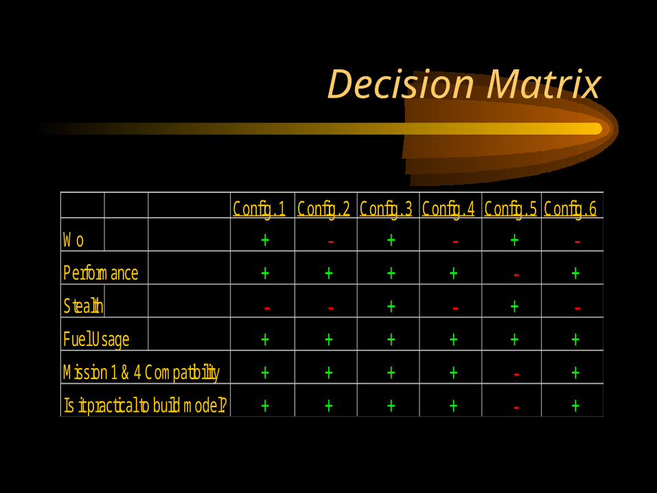
Decision Matrix
Config. 1 Config. 2 Config. 3 Config. 4 Config. 5 Config. 6
Wo + - + - + -Performance + + + + - +Stealth - - + - + -Fuel Usage + + + + + +Mission 1 & 4 Compatibility + + + + - +Is it practical to build model? + + + + - +

Final Design
60 ft
38 ft.
23 ft.
7 ft.
TOGW - 25125 lbs Fuel weight - 9170 lbsT/W - 1.19 (takeoff), .588(combat)L/D - 14(unswept), 12(swept), 7(dash)W/S - 70(takeoff), 35.8(combat)Max Mach 1.6Wetted area/Wing area = 4.8
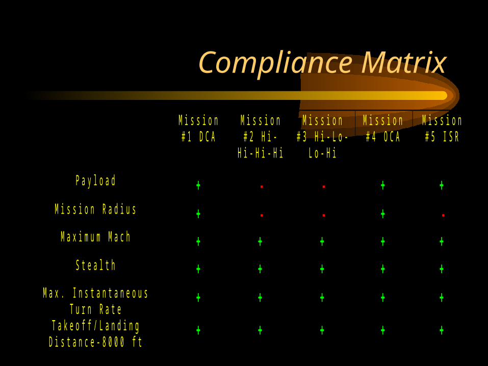
Compliance Matrix
M i s s i o n# 1 D C A
M i s s i o n# 2 H i -
H i - H i - H i
M i s s i o n# 3 H i - L o -
L o - H i
M i s s i o n# 4 O C A
M i s s i o n# 5 I S R
P a y l o a d + - - + +M i s s i o n R a d i u s + - - + -M a x i m u m M a c h + + + + +
S t e a l t h + + + + +M a x . I n s t a n t a n e o u s
T u r n R a t e+ + + + +
T a k e o f f / L a n d i n gD i s t a n c e - 8 0 0 0 f t
+ + + + +

AerodynamicsCdo vs Mach
0.02
0.03
0.04
0.05
0.06
0 0.5 1 1.5 2
Mach #
Cdo
Lift Curve Slope Vs. MACH #
0
0.5
1
1.5
2
2.5
0 0.2 0.4 0.6 0.8 1 1.2 1.4 1.6 1.8
MACH #
CLalp
ha
K vs MACH #
0
0.05
0.1
0.15
0.2
0.25
0 0.5 1 1.5 2
MACH #
K
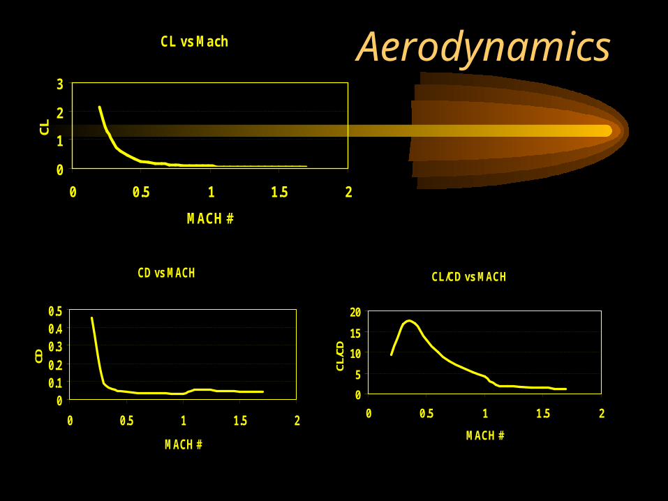
AerodynamicsCL vs Mach
0
1
2
3
0 0.5 1 1.5 2
MACH #
CL
CD vs MACH
00.10.20.30.40.5
0 0.5 1 1.5 2
MACH #
CD
CL/CD vs MACH
0
5
10
15
20
0 0.5 1 1.5 2
MACH #
CL/C
D
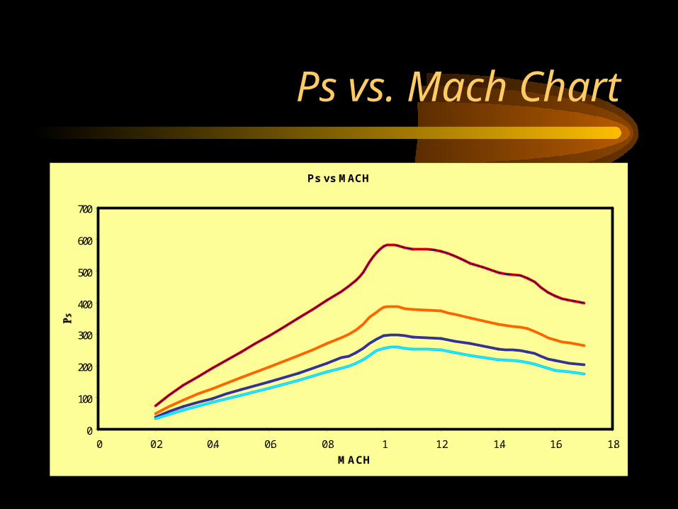
Ps vs. Mach Chart
Ps vs MACH
0
100
200
300
400
500
600
700
0 0.2 0.4 0.6 0.8 1 1.2 1.4 1.6 1.8
MACH
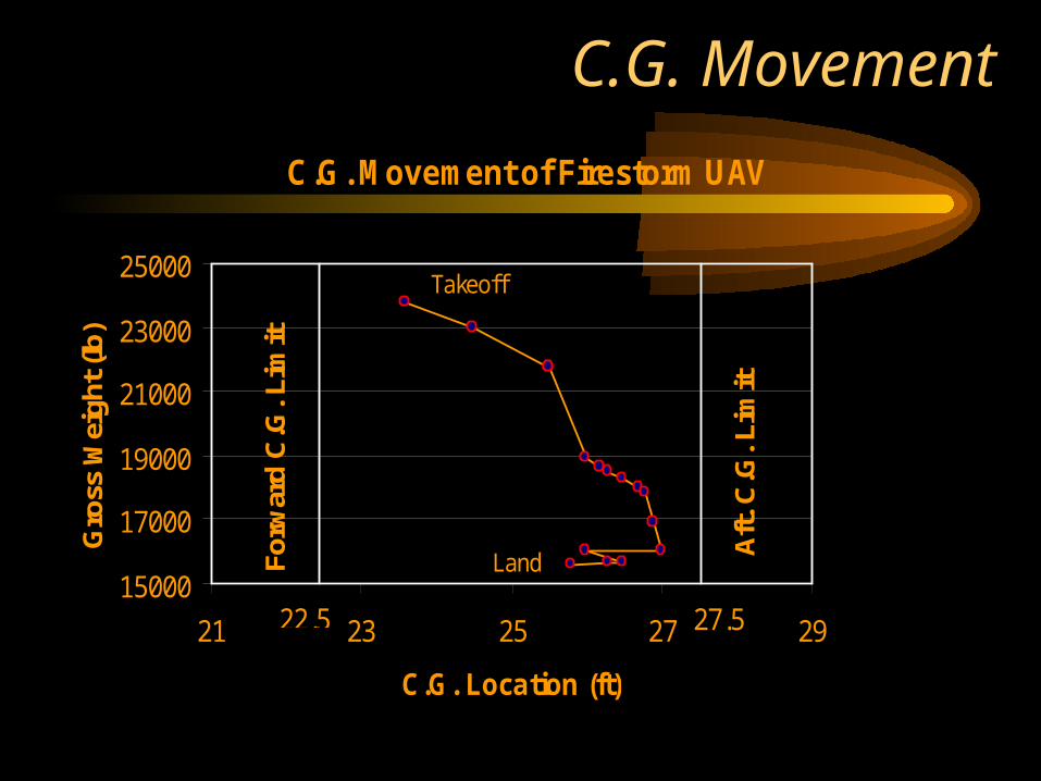
C.G. Movement
C.G. Movement of Firestorm UAV
15000
17000
19000
21000
23000
25000
21 23 25 27 29
C.G. Location (ft)
Gro
ss W
eigh
t (lb
)
22.5 27.5
Forw
ard
C.G
. Lim
it
Aft.
C.G
. Lim
it
Takeoff
Land
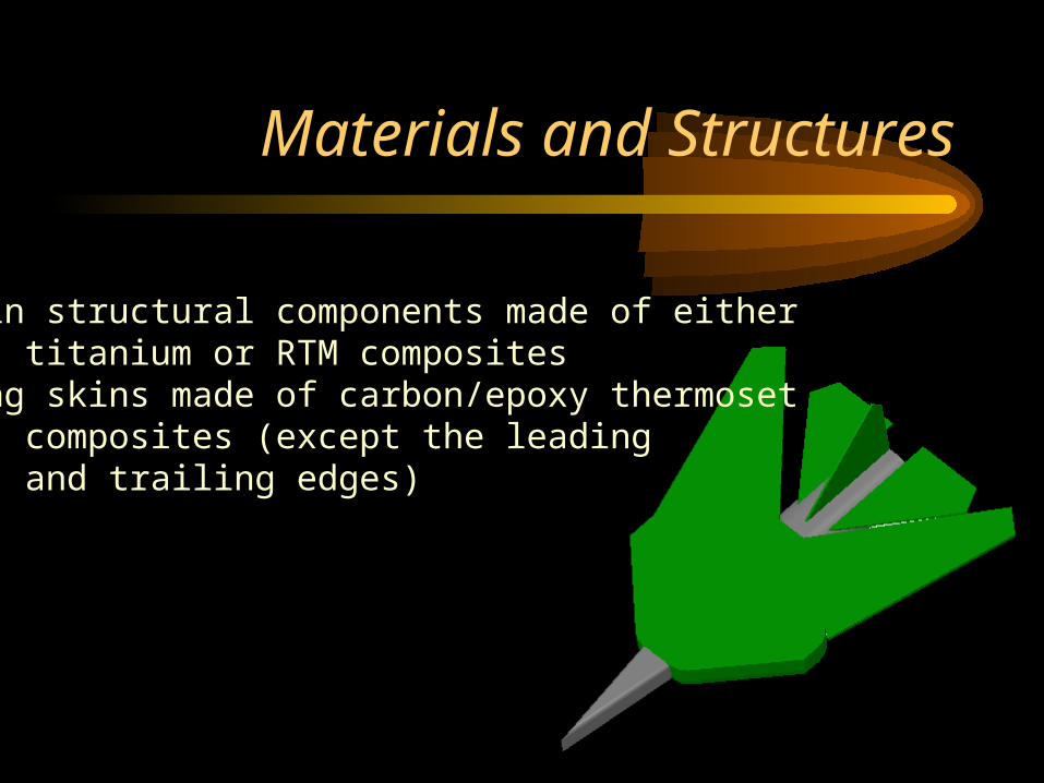
Materials and Structures
-Main structural components made of either titanium or RTM composites
-Wing skins made of carbon/epoxy thermosetcomposites (except the leadingand trailing edges)

V-n Diagram
-10
-8
-6
-4
-2
0
2
4
6
8
10
12
14
16
18
0 100 200 300 400 500 600 700 800 900 1000 1100 1200
Velocity (Mph)
N (lo
ad fac
tor)
Np = 16.7g
Vc = 1.2M (813 mph)
Nn = -8g
Vs curve
Inverted VsCurve
Vs = 141 mph
Vmax = 1.6M
(1084 mph)
Stall speed@ 16.7g = 578mph

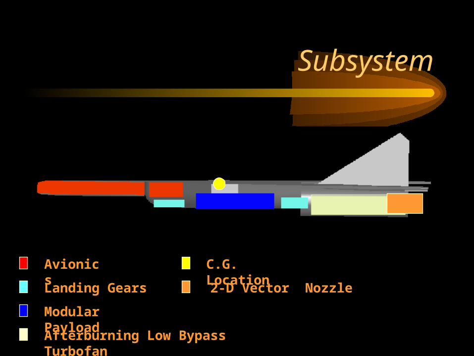
Subsystem
Avionics
Fuel Tanks
Subsystem
Avionics
Landing Gears
Modular Payload
Afterburning Low Bypass Turbofan
C.G. Location
2-D Vector Nozzle

Subsystem
Variable Geometry Armpit Air Inlets w/ Channel-Type Boundary Layer Diverter
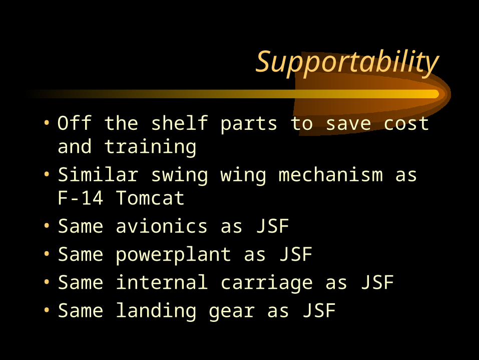
Supportability
• Off the shelf parts to save cost and training
• Similar swing wing mechanism as F-14 Tomcat
• Same avionics as JSF
• Same powerplant as JSF
• Same internal carriage as JSF
• Same landing gear as JSF
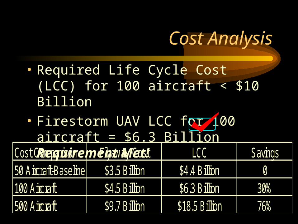
Cost Analysis
• Required Life Cycle Cost (LCC) for 100 aircraft < $10 Billion
• Firestorm UAV LCC for 100 aircraft = $6.3 Billion Requirement Met!
Cost Comparison Flyaway Cost LCC Savings50 Aircraft-Baseline $3.5 Billion $4.4 Billion 0100 Aircraft $4.5 Billion $6.3 Billion 30%500 Aircraft $9.7 Billion $18.5 Billion 76%
Conclusion and Future Work Needed
• Initial design phase over
• Design factors achieved (low cost, stealth, etc…)
• Further trade studies of T/W and W/S
• Detailed study of vector nozzles
• Aircraft mockup
• Wind tunnel testings

Conclusions and Further Work Needed (cont.)...
• Perform FEA
• Build and fly test vehicle
Related Documents