GITAM INSTITUTE OF TECHNOLOGY (Department of Electronics and Communication Engineering) GITAM UNIVERSITY VISHAKAPATNAM REPORT ON "STUDY OF PROGRAMMABLE LOGIC CONTROLLER" submitted as a part of industrial training done by Y.MADHAVA REDDY Regd no:1210409365

Welcome message from author
This document is posted to help you gain knowledge. Please leave a comment to let me know what you think about it! Share it to your friends and learn new things together.
Transcript

GITAM INSTITUTE OF TECHNOLOGY
(Department of Electronics and Communication Engineering)
GITAM UNIVERSITY
VISHAKAPATNAM
REPORT ON
"STUDY OF PROGRAMMABLE LOGIC CONTROLLER"
submitted as a part of industrial training done by
Y.MADHAVA REDDY
Regd no:1210409365
BHARAT HEAVY ELECTRICALS LIMITED.
Ramachandra Puram,Hyderabad

ACKNOWLEDGEMENT
We would like to take this opportunity and express our heartfelt thanks to all those who helped
us in the course of this project work.
We are very much grateful to BHARAT HEAVY ELECTRICALS LIMITED for providing with real
data regarding the functioning of organization and we take this opportunity to express our
heartfelt gratitude to Mr.L.SHANKAR SINGH, ENGINEER (M&S), B.H.E.L., for having permitted
us to undertake the project in the organization and encouraging in completing this project
successfully.
We would like to convey our thanks to other staff members, who also guided us in our
endeavors and also extending their helping hands.
1. INTRODUCTION TO BHEL
BHEL is the largest engineering and manufacturing enterprise in India in the energy related/infrastructure sector today. BHEL was established more than 40 years ago ushering in the indigenous Heavy Electrical Equipment industry in India, a dream that has been more than realized with a well-recognized track record of performance. It has been earning profits continuously since 1971-72 and paying dividends since 1976-77.
BHEL manufactures over 180 products under 30 major product groups and caters to core sectors of the Indian Economy viz., Power Generation & Transmission, Industry, Transportation, Telecommunication, Renewable Energy, etc. The wide network of BHEL's 14 manufacturing divisions, four Power Sector regional centers, over 100 project sites, eight service centers and 18 regional offices, enables the Company to promptly serve its customers and provide them with suitable products, systems and services - efficiently and at competitive prices.
The quality & reliability of its products is due to the emphasis on design, engineering and manufacturing to international standards by acquiring and adapting some of the best technologies from leading companies in the world, together with technologies developed in its own R&D centers.
BHEL has acquired certifications to Quality Management Systems – ISO 9001, Environmental Management Systems – ISO 14001 and Occupational Health & Safety Management Systems – OHSAS 18001 and has also adopted the concepts of Total Quality Management.
BHEL has Installed equipment for over 90,000 MW of power generation - for Utilities, Captive and Industrial users.
Supplied over 2,25,000 MVA transformer capacity and sustained equipment operating in Transmission & Distribution network upto 400 KV - AC & DC.
Supplied over 25,000 Motors with Drive Control System to Power projects, Petrochemicals, Refineries, Steel, Aluminum, Fertilizer, Cement plants, etc.
Supplied Traction electrics and AC/DC locos to power over 12,000 Kms Railway network.
Supplied over 2,25,000 MVA transformer capacity and sustained equipment operating in Transmission & Distribution network upto 400 KV - AC & DC.

Supplied over one million Valves to Power Plants and other Industries.
BHEL's operations are organized around three business sectors, namely Power, Industry including Transmission, Transportation, Telecommunication & Renewable Energy and Overseas Business. This enables BHEL to have a strong customer orientation, to be sensitive to his needs and respond quickly to the changes in the market.
BHEL's vision is to become a world class engineering enterprise, committed to enhance stakeholder value. The company is striving to give shape to its aspirations and fulfill the expectations as a ‘Navratna' Company.
The greatest strength of BHEL is its highly skilled and committed 44,000 employees. Every employee is given an equal opportunity to develop himself and improve his position. Continuous training and retraining, career planning, a positive work culture and participative style of management have engendered development of a committed and motivated work force leading to enhanced productivity and higher levels of quality.
Project Engineering Department in BHEL Hyderabad Unit is mainly performing the engineering, procurement, inspection activities for Balance of Plant equipments for Captive and Utility power plants mainly Gas Turbine based.
Control & Instrumentation Group is involved in engineering, procurement, inspection of various field instruments, safety & control valves, cables, etc for the power plants. Also involved in providing overall plant control system using various makes of Distributed Control Systems (DCS) and Programmable Logic Controllers (PLCs).

ABSTRACT
A programmable logic controller (PLC) or programmable controller is a digital computer used for automation of electromechanical processes, such as control of machinery on factory assembly lines, amusement rides, or light fixtures . PLCs are used in many industries and machines. Unlike general-purpose computers, the PLC is designed for multiple inputs and output arrangements, extended temperature ranges, immunity to electrical noise, and resistance to vibration and impact. Programs to control machine operation are typically stored in battery-backed-up or non-volatile memory. A PLC is an example of a hard real time system since output results must be produced in response to input conditions within a limited time, otherwise unintended operation will result.
The main difference from other computers is that PLCs are armoured for severe conditions (such as dust, moisture, heat, cold) and have the facility for extensive input/output (I/O) arrangements. These connect the PLC to sensors and actuators. PLCs read limit switches, analogy process variables (such as temperature and pressure), and the positions of complex positioning systems. Some use machine vision. On the actuator side, PLCs operate electric motors, pneumatic or hydraulic cylinders, magnetic relays, solenoids, or analogy outputs. The input/output arrangements may be built into a simple PLC, or the PLC may have external I/O modules attached to a computer network that plugs into the PLC

PROGRAMMABLE LOGIC CONTROLLER(PLC)
CONTENTS:
BHEL-An Over View
-Power Generation
-Power Transmission And Distribution
-Industries
-Transportation
-Technology Up -gradation And R & D
PLC Organisation
PLC Resources
Programming Structures
Introduction To NHCNC Machines &
Introduction To FAGOR 8040 CNC Systems
Technical specifications of FAGOR 8040
FAGOR 8040 Module Structure
-Directing Instructions
-Axes & Coordinate System
PLC Programming Examples
-Motor Starter Example
-Program Instructions
Expanding The Application
PLC Resources Of FAGOR 8040
PLC Program

PLC ORGANISATION
PLC (Programmable logic controller):
PLC is a digitally operating electronic apparatus which uses a programmable memory for
the internal storage of instructions for implementing specific functions such as logic,
sequencing, timing, counting and arithmetic to control various types of machines and
processors. A PLC monitors inputs, makes decisions based on its program, and controls outputs
to automate a process or machine. The inputs can be from sensors like push buttons, switches
etc. and the outputs go to devices like lamps, motors, pumps etc.
Block diagram of PLC:
PLCs consist of input modules or points, a Central Processing Unit (CPU) and output
modules or points. An input accepts a variety of digital or analog signals from various field
devices (sensors) and converts them into a logic signal that can be used by the CPU. The CPU
makes decisions and executes control instructions based on program instructions in memory.

Output modules convert control instructions from the CPU into a digital or analog signal that
can be used to control various field devices (actuators). A programming device is used to input
the desired instructions. These instructions determine what the PLC will do for a specific input.
An operator interface device allows process information to be displayed and new control
parameters to be entered.
It consists of various buses for transmission of information from one module to another
module. They are:
Address Bus: select the address (memory locations) on the individual members)
Data Bus: It carries data (content of the memory location
Control bus: Transfers control and timing signals for the synchronization of CPU’s
activities within the programmable controller

PLC RESOURCES
(All the values like number of inputs, outputs, marks, etc. refer to the FAGOR 8040 machine
specifications)
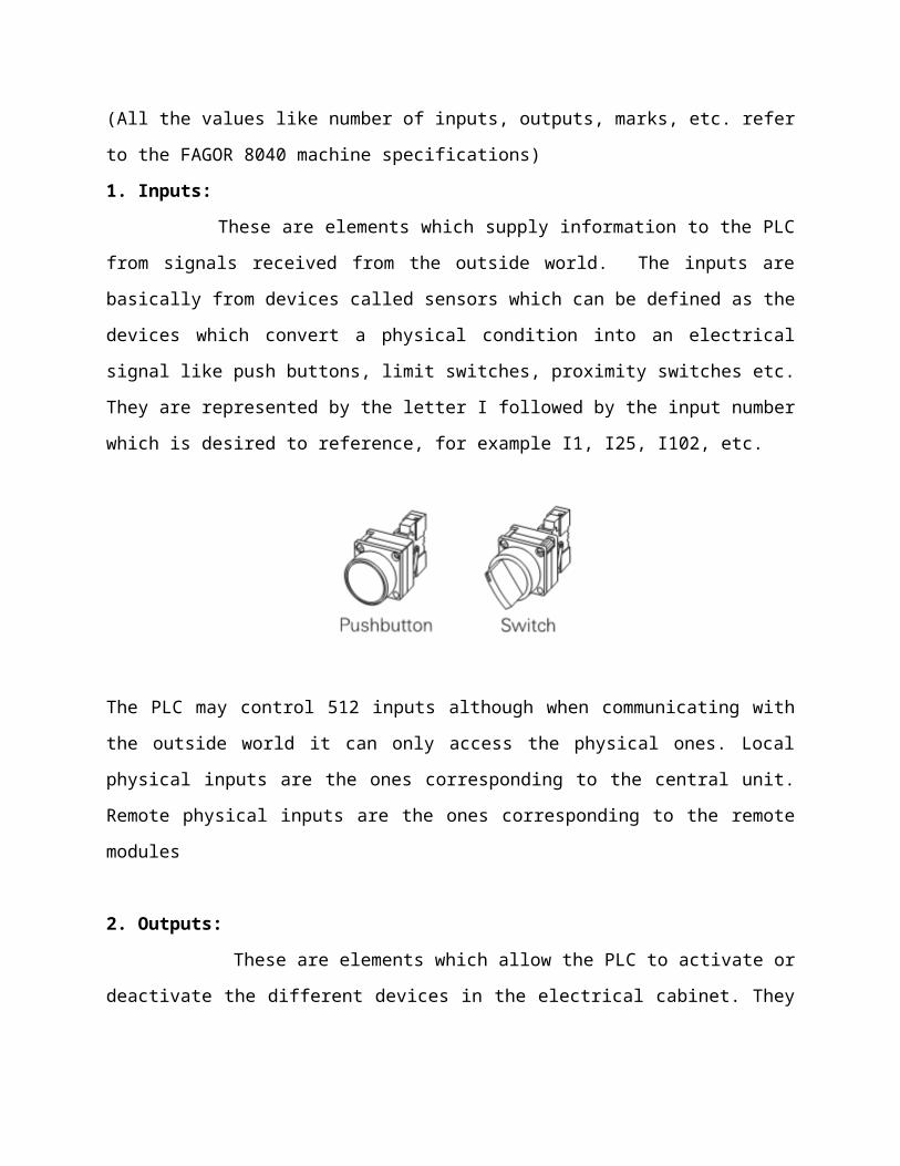
1. Inputs:
These are elements which supply information to the PLC from signals received from the
outside world. The inputs are basically from devices called sensors which can be defined as the
devices which convert a physical condition into an electrical signal like push buttons, limit
switches, proximity switches etc. They are represented by the letter I followed by the input
number which is desired to reference, for example I1, I25, I102, etc.
The PLC may control 512 inputs although when communicating with the outside world it can
only access the physical ones. Local physical inputs are the ones corresponding to the central
unit. Remote physical inputs are the ones corresponding to the remote modules
2. Outputs:
These are elements which allow the PLC to activate or deactivate the different devices in
the electrical cabinet. They are represented by the letter O followed by the output number
which is desired to reference, for example O1, O25, O102, etc.

The PLC may control 512 outputs although when communicating with the outside world it
can only access the physical ones. Local physical outputs are the ones corresponding to the
central unit. Remote physical outputs are the ones corresponding to the remote modules.
Output O1 coincides with the emergency output of the CNC (connector); thus, it must be kept
high (logic level 1).
I/O Numbering: The numbering conventions can differ from one manufacturer to another.
For example, the above convention is from FAGOR. In SIEMENS, I designate a discrete input
and Q designates a discrete output. The first number identifies the byte; the second number
identifies the bit. Input I0.0, for example, is byte 0, bit 0. Both the above conventions are used
throughout the remaining of this text.
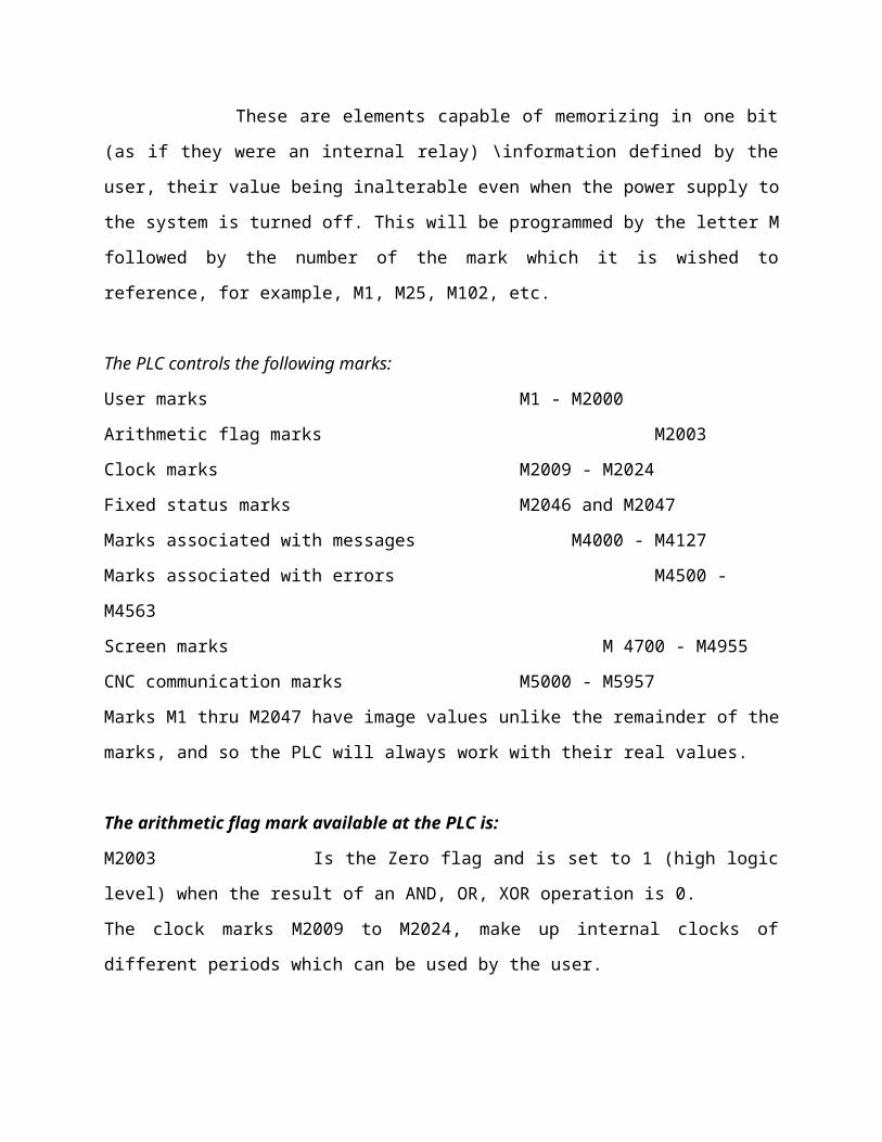
3.Marks:
These are elements capable of memorizing in one bit (as if they were an internal relay) \
information defined by the user, their value being inalterable even when the power supply to
the system is turned off. This will be programmed by the letter M followed by the number of
the mark which it is wished to reference, for example, M1, M25, M102, etc.
The PLC controls the following marks:
User marks M1 - M2000
Arithmetic flag marks M2003
Clock marks M2009 - M2024
Fixed status marks M2046 and M2047
Marks associated with messages M4000 - M4127
Marks associated with errors M4500 - M4563
Screen marks M 4700 - M4955
CNC communication marks M5000 - M5957
Marks M1 thru M2047 have image values unlike the remainder of the marks, and so the PLC
will always work with their real values.
The arithmetic flag mark available at the PLC is:
M2003 Is the Zero flag and is set to 1 (high logic level) when the result of an AND, OR,
XOR operation is 0.
The clock marks M2009 to M2024, make up internal clocks of different periods which can be
used by the user.
The fixed status marks available at the PLC are:
M2046 Always has a value of 0.
M2047 Always has a value of 1.
The PLC allows, by means of the activation of a series of message marks, the PLC message
corresponding to the PLC message table to be displayed on the CNC screen. They can be named
by means of the mark M4000 - M4127 or by means of their associated mnemonic MSG1 -
MSG128:
Likewise, 64 error marks are available which allow the error corresponding to the PLC error
table to be displayed on the CNC screen as well as to interrupt the execution of the CNC
program, stopping axis feed and spindle rotation. Activating any of these marks does not
activate the external CNC emergency output.

They can be named by means of mark M4500-M4563 or by means of their associated
mnemonic ERR1 - ERR64:
Because the PLC program is not interrupted by these marks, it is advised to make it possible to
change their status via accessible external inputs; otherwise, the CNC will keep receiving the
same error at every PLC scan (cycle) thus preventing access to any PLC mode.
By activating one of the marks M4700-M4955 user pages 0-255 can be activated in the CNC.
They can be named by means of mark M4700-M4955 or by means of their associated
mnemonic PIC0 - PIC255:
4. Registers:
These are elements which store a numerical value in 32 bits, their value remaining
unalterable even when the power supply to the system is cut off. They do not have image
values and are represented by the letter R, followed by the register number it is desired to
reference, for example R1, R25, R102, etc.
The PLC has the following registers:
User registers R1 - R499
Registers for communication with the CNC R500 - R559
The PLC will consider each value stored in each register as an integer with a sign, and can be
within ±2147483647.
It is also possible to make reference to a BIT of the REGISTER by putting the letter B and the bit
number (0/31) in front of the selected register. For example:
B7R155 Refers to bit 7 of register 155.
The PLC considers bit 0 as being the one with least significance and bit 31 as being the one with
most significance.
The value stored in a register can be treated as being decimal, hexadecimal, binary or BCD for
example:
decimal 156
Hexadecimal $9C
Binary B0000 0000 0000 0000 0000 0000 1001 1100
5. TIMERS:
These are elements capable of maintaining their output at a determined logic level
during a preset time (time constant), after which the output changes status. They do not have
image values and are represented by the letter T, followed by the number of the timer it is
required to reference, for example, T1, T25, T102, etc. The time constant is stored in a 32-bit
variable, and so its value can be between 0 and 4294967295 milliseconds, which is equivalent
to 1193 hours (almost 50 days). The PLC has 256 timers, each of which has T status output and
TEN, TRS, TG1, TG2,
TG3 and TG4 inputs. It is also possible to consult at any moment the time which has elapsed
from the moment it was activated.

Enable Input (TEN):
This input allows the timing of the timer to be stopped. It is referred to by the letter TEN
followed by the number of the timer which is wished to reference, for example TEN 1, TEN 25,
TEN 102, etc.
So that the time elapses within the timer this input must be at level “1”. By default and
every time a timer is activated the PLC will assign this input a logic level of “1”. If, once the
timer is activated, TEN = 0 is selected, the PLC stops timing, and it is necessary to assign TEN = 1
for this timing to continue.
Reset Input (RES):
This input allows the timer to be initialized, by assigning the value 0 to its T status and by
cancelling its count (it initializes this to 0). It is referred to by the letters TRS followed by the
timer number it is wished to reference, for example TRS 1, TRS 25, TRS 102, etc.
This initialization of the timer will be made when a transition of logic level from “0” to “1”
(leading edge) is produced. By default and every time a timer is activated the PLC will assign this
input a logic level of “0”. If, once the timer is activated, a leading edge is produced at the TRS
input, the PLC initializes the timer, assigning value 0 to its T status and cancelling the count (it
initializes this to 0). Additionally, the timer is deactivated it being necessary to activate its
trigger input to activate it again.

Status Output (T):
This output indicates the logic status of the timer. It is referred to by the letter T followed
by the number of the timer which it is required to reference, for example T1, T25, T102, etc.
The logic status of the timer depends on the operating mode selected by means of the
trigger inputs TG1, TG2, TG3 and TG4, and so the activation or deactivation of this signal is
explained in each of the PLC operating modes.
Elapsed Time (t):
This output indicates the time elapsed in the timer since the moment it was activated. It is
referred to by the letter T followed by the number of the timer which it is required to reference,
for example T1, T25, T102, etc.
Although when written as T123 it coincides with the status output, both are different and they
are also used in different types of instruction.
Trigger Inputs (TG1, TG2, TG3, TG4):
These inputs allow the timer to be activated, and it begins to time. They are referred to
by the letters TG1, TG2, TG3, TG4 followed by the number of the timer it is required to
reference and the value which is required to start the count with (time constant).
The time constant value is defined in thousandths of a second, and it is possible to indicate this
by means of a numerical value or by assigning it the internal value of an R register.
Inputs TG1, TG2, TG3 and TG4 are used to activate the timer in four
different operating modes:
TG1 input in MONOSTABLE mode
TG2 input in DELAYED CONNECTION mode
TG3 input in DELAYED DISCONNECTION mode
TG4 input in SIGNAL LIMITING mode

This activation of the timer is made when a logic level transition of any of these inputs is
produced, either from “0” to “1” or from “1” to “0” (leading or trailing edge) depending on the
chosen input. By default and every time the timer is initialized by means of the reset input
(TRS), the PLC will assign logic level “0” to these inputs.
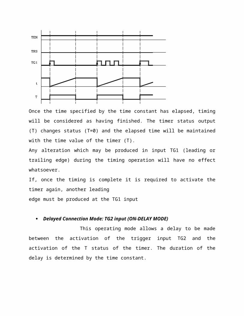
Monostable mode: TG1 Input
In this operational mode the timer status is kept at the high logic level (T=1) from the moment
the TG1 input is activated until the time indicated by the time constant elapses.
If the timer is initialized with values TEN=1 and TRS=0, the timer will be activated when a
leading edge is produced at input TG1. At that moment, the timer status output (T) changes
status (T=1) and timing t starts from a value of 0.

Once the time specified by the time constant has elapsed, timing will be considered as having
finished. The timer status output (T) changes status (T=0) and the elapsed time will be
maintained with the time value of the timer (T).
Any alteration which may be produced in input TG1 (leading or trailing edge) during the timing
operation will have no effect whatsoever.
If, once the timing is complete it is required to activate the timer again, another leading
edge must be produced at the TG1 input
Delayed Connection Mode: TG2 input (ON-DELAY MODE)
This operating mode allows a delay to be made between the activation of the trigger
input TG2 and the activation of the T status of the timer. The duration of the delay is
determined by the time constant.
If the timer is initialized with values TEN=1 and TRS=0, the timer will be activated when a
leading edge is produced at TG2 input. At that moment, timing t will start from a value of 0.
Once the time specified by the time constant has elapsed the timing operation will be
considered as having completed and the timer status output (T=1) will be activated and will
remain in this status until the trailing edge is produced in the trigger input TG2.
The elapsed time will remain as a timer time value (T) once timing has been completed.

If, once the timing has finished, it is required to activate the timer again, another leading
edge must be produced in the TG2 input.
If the trailing edge of the trigger input TG2 is produced before the time specified by the time
constant has elapsed, the PLC will consider that the timing operation has concluded,
maintaining the time count it had at that moment as the timer time (T).
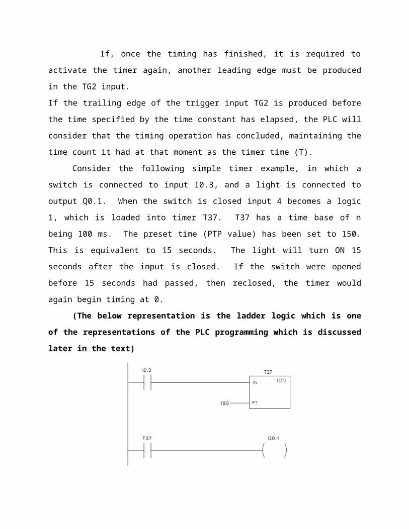
Consider the following simple timer example, in which a switch is connected to input
I0.3, and a light is connected to output Q0.1. When the switch is closed input 4 becomes a logic
1, which is loaded into timer T37. T37 has a time base of n being 100 ms. The preset time (PTP
value) has been set to 150. This is equivalent to 15 seconds. The light will turn ON 15 seconds
after the input is closed. If the switch were opened before 15 seconds had passed, then
reclosed, the timer would again begin timing at 0.
(The below representation is the ladder logic which is one of the representations of
the PLC programming which is discussed later in the text)

A small sample of the flexibility of PLCs is shown in the following program logic. By
reprogramming the T37 contact as a normally closed contact, the function of the circuit is
changed to cause the indicator light to turn OFF only when the timer times out. This function
change was accomplished without changing or rewiring I/o devices.
TG3 – DELAYED DISCONNECTION MODE (OFF- DELAY MODE)
The OFF-delay tier is used to delay an output off for a fixed period of time after the input
turns off. When the enabling bit turns ON, the timer bit turns ON immediately and the value is
set to 0. When the input turns OFF, the timer counts until the preset time has elapsed before
the timer bit turns OFF.

6. COUNTERS
These are elements capable of counting up or down a specific amount of events. Counters
compare an accumulated value to a preset value to control circuit functions. Control
applications that commonly use counters include the following:
Count to a preset value and cause an event to occur.
Cause and even to occur until the count reaches a preset value.
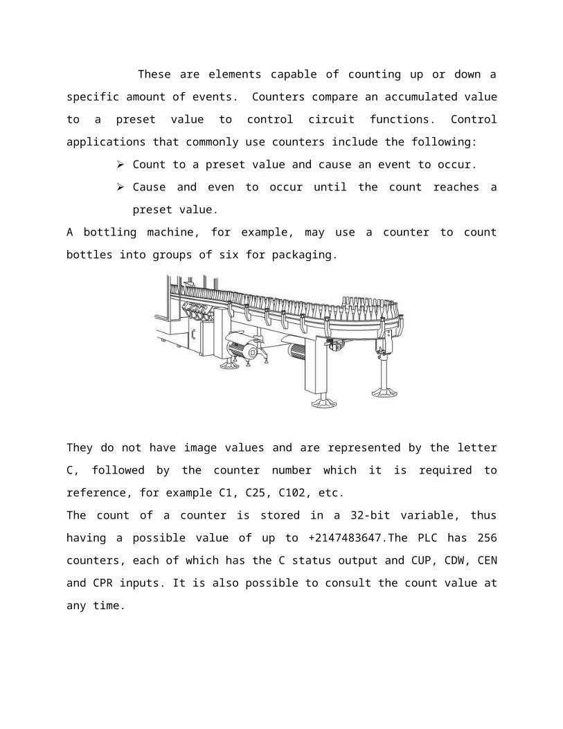
A bottling machine, for example, may use a counter to count bottles into groups of six for
packaging.
They do not have image values and are represented by the letter C, followed by the counter
number which it is required to reference, for example C1, C25, C102, etc.
The count of a counter is stored in a 32-bit variable, thus having a possible value of up to
+2147483647.The PLC has 256 counters, each of which has the C status output and CUP, CDW,
CEN and CPR inputs. It is also possible to consult the count value at any time.
Feedback input (CUP):
This input allows the counter count to be increased in a unit every time a leading edge is
produced in it. It is referred to by the letters CUP followed by the counter number which is
required to reference, for example CUP 1, CUP 25, CUP 102, etc.
Example:
I2 = CUP 10 Every time a leading edge is produced at input I2 the counter count C10 will be
increased.
Count-down input (CDW):
This input allows the counter count to be decreased in a unit every time a leading edge is
produced in it. It is referred to by the letters CDW followed by the counter number which is
required to reference, for example CDW 1, CDW 25, CDW 102, etc.
Example:
I3 = CDW 20 Every time a leading edge is produced at input I3 the counter count C20 will be
decreased.
Enable input (CEN):
This input allows the internal counter count to be stopped. It is referred to by the letters
CPR followed by the number of the counter which is required to reference for example CEN 1,
CEN 25, CEN 102, etc.

In order to be able to modify the internal count by means of the inputs CUP and CDW this input
must be at logic level “1”. By default and every time a counter is activated the PLC will assign
this input a logic level of “1”.
If CEN = 0 is selected the PLC stops the counter count, ignoring the inputs CUP and CDW until
this input allows it (CEN = 1).
Example:
I10 = CEN 12 Input I10 controls the enable input of counter C12.
Preset input (CPR):
This input allows the counter to be preset with the desired value. It is referred to by the
letters CPR followed by the number of the counter which is required to reference and the value
to be assigned to the counter count.
For example
CPR 1 100, CPR 25 224, CPR 102 0, CPR 200 500, etc.
The value of the count can be indicated by means of a numerical value or by assigning to it the
internal value of an R register.
CPR 20 100 Presets the C20 counter to a value of 100.
CPR 22 R200 Presets the C22 counter with the value of the Register R200 when the
instruction is executed.
The counter is preset with the value when a leading edge is produced at the CPR input.
Status output (C):
This output indicates the logic status of the counter. It is referred to by the letter C,
followed by the counter number which is required to reference, for example C1, C25, C102, etc.
The logic status of the counter will be C=1 when the value of the count is zero and C=0 in the
remainder of cases.
Count value (C):
This output indicates the value of the internal counter count. It is referred to by the letter C,
followed by the counter number which is required to reference, for example C1, C25, C102, etc.
Although when written C123 it coincides with the status output, both are different and, are
used in different types of instructions.
In binary type instructions function C123 makes reference to the counter’s logic status.
C123 = M100 Assigns mark to M100 the status (0/1) of counter 123.
UP COUNTER:
The UP counter counts up from a current value to a preset value(PV). Input CU is the
count input. Input CU is the count input. Each time CU transition from a logic 0 to a logic 1 the
counter increments by a count of 1. Input R is reset. A preset count value is stored in PV input.
If the current count is equal to or greater than the preset value stored in PV, the output bit (Q)
turns on.

DOWN COUNTER:
The down counter counts down from the preset value (PV) each time CD transitions
from logic 0 to logic 1. When the current value is equal to zero the counter output bit (Q) turns
on (not shown). The counter resets and loads the current value with the preset value (PV) when
the load input (LD) is enabled.
UP/DOWN COUNTER:
The up/down counters counts up or down from the preset value each time either CD or
CU transitions from a logic 0 to a logic 1. When the current value is equal to the preset value,
the output QU turns on. When the current value (CV) is equal to zero, the output QD turns on.
The counter loads the current value (CV) with the preset value (PV) when the load input (LD) is
enabled. Similarly, the counter resets and loads the current value (CV) with zero when the reset
(R) is enabled. The counter stops counting when it reaches preset or zero.
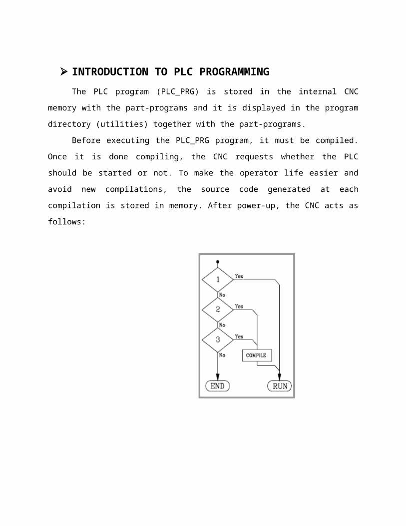
INTRODUCTION TO PLC PROGRAMMING
The PLC program (PLC_PRG) is stored in the internal CNC memory with the part-
programs and it is displayed in the program directory (utilities) together with the part-
programs.
Before executing the PLC_PRG program, it must be compiled. Once it is done compiling,
the CNC requests whether the PLC should be started or not. To make the operator life easier
and avoid new compilations, the source code generated at each compilation is stored in
memory. After power-up, the CNC acts as follows:

Modular structure of the program:
The program to be executed by the PLC consists of a series of modules which are
appropriately defined by means of directing instructions.
The modules which can make up the program are:
Main module (PRG)
Periodic execution module (PE)
First cycle module (CY1)
Each module must begin with the directing instruction which defines it (PRG, PE, CY1)
and end with the directing instruction END.
Should the main program contain the main module only it is not necessary to place the
instructions PRG and END?
First cycle module (CY1):
This module is optional and will only be executed when the PLC is turned on. It is used
to initialize the different resources and variables with their initial values, before proceeding to
execute the rest of the program.

This module operates by default with the real values of resources I, O, M. It is not
necessary for this to be at the beginning of the program, but must always be preceded by the
instruction CY1.
Main module (PRG);
This module contains the user program. It will be executed cyclically and will be given
the task of analysing and modifying CNC inputs and outputs. Its execution time will be limited
by the value of plc.m.p. WDGPRG (P0) .This module operates by default with the image values
of resources I, O, M. There can only be one main program and this must be preceded by the
instruction PRG, it is not necessary to define it if it starts on the first line.
Periodic execution module (PE t):
This module is optional and will be executed every period of time t indicated in the
directing instruction defining the module. This module may be used to process certain critical
inputs and outputs which cannot be checked or updated properly in the body of the main
program due to its extended execution time.
Another application for this module is for those cases where specific tasks need not be
evaluated at every PLC program cycle. Those tasks would be programmed in the periodic
module and they would be executed with the frequency established by the execution time
assigned to this module (for example: if t= 30,000; every 30 seconds).
A “t” value between 1 and 65535 milliseconds may be programmed. The execution time
of this module will be limited by the value of plc.m.p. WDGPER (P1). This module operates by
default with the real values of resources I, O, M.
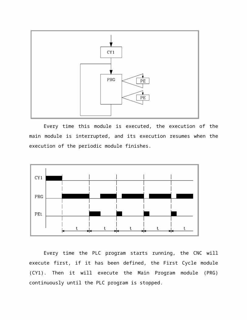
Priority of execution of the PLC modules:
Every time the PLC program is started (command RUN) the first module to be executed
is the first cycle module (CY1). Once execution has been completed, it will continue with the
main module (PRG). The main module will be executed cyclically until the execution of the PLC
has stopped (command STOP).

0The periodic module will be executed every time the time indicated in the directing instruction
“PE t” elapses. This count starts when the execution of the main module (the first time) begins.
Every time this module is executed, the execution of the main module is interrupted,
and its execution resumes when the execution of the periodic module finishes.
Every time the PLC program starts running, the CNC will execute first, if it has been
defined, the First Cycle module (CY1). Then it will execute the Main Program module (PRG)
continuously until the PLC program is stopped.

The periodic execution modules (PE) will be executed every so often with the frequency
established for each of them. This time period starts counting from the time the CY1 cycle is
ended. The execution of a periodic module temporarily interrupts the execution of the main
module.
PROGRAMMING STRCTURES
A program consists of one or more instructions that accomplish a task. Programming a
PLC is simply constructing a set of instructions. There are several ways to look at a program
such as ladder logic, statement lists, or function block diagrams.
Ladder logic:
Ladder logic (LAD) is one programming language used with PLCs. Ladder logic uses
components that resemble elements used in a line diagram format to describe hard-wired
control.
Ladder logic diagram:
The left vertical line of a ladder logic diagram represents the power or energized conductor. The
output element or instruction represents the neutral or return path of the circuit. The right
vertical line, which represents the return path on a hard-wired control line diagram, is omitted.
Ladder logic diagrams are read from left-to-right, top-to-bottom. Rungs are sometimes referred
to as networks. A network may have several control elements, but only one output coil.

Statement list:
A statement list (STL) provides another view of a set of instructions. The operation, what
is to be done, is shown on the left. The operand, the item to be operated on by the operation, is
shown on the right. A comparison between the statement list shown below, and the ladder
logic shown on the previous page, reveals a similar structure. The set of instructions in this
statement list perform the same task as the ladder diagram.
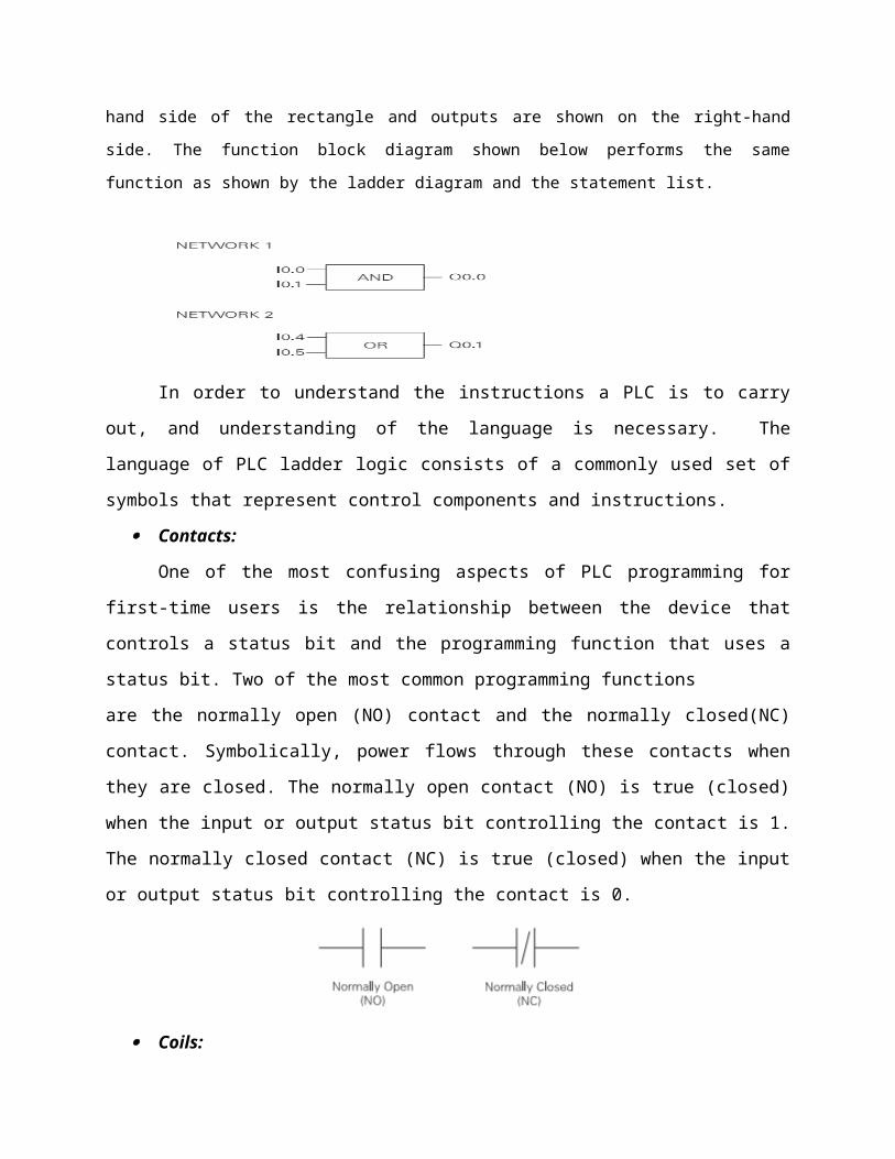
Function Block Diagrams :
Function Block Diagrams (FBD) provide another view of a set of instructions. Each function has a
name to designate its specific task. Functions are indicated by a rectangle. Inputs are shown on the left-
hand side of the rectangle and outputs are shown on the right-hand side. The function block diagram
shown below performs the same function as shown by the ladder diagram and the statement list.
In order to understand the instructions a PLC is to carry out, and understanding of the
language is necessary. The language of PLC ladder logic consists of a commonly used set of
symbols that represent control components and instructions.
Contacts:
One of the most confusing aspects of PLC programming for first-time users is the
relationship between the device that controls a status bit and the programming function that
uses a status bit. Two of the most common programming functions
are the normally open (NO) contact and the normally closed(NC) contact. Symbolically, power
flows through these contacts when they are closed. The normally open contact (NO) is true
(closed) when the input or output status bit controlling the contact is 1. The normally closed
contact (NC) is true (closed) when the input or output status bit controlling the contact is 0.
Coils:
Coils represent relays that are energized when power flows to them. When a coil is energized,
it causes a corresponding output to turn on by changing the state of the status bit controlling
that output to 1. That same output status bit may be used to control normally open and
normally closed contacts elsewhere in the program.
Boxes:
Boxes represent various instructions or functions that are executed when power flows
to the box. Typical box functions are timers, counters, and math operations.
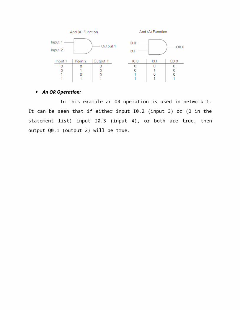
AND Operation:
Each rung or network on a ladder represents a logic operation. The following
programming example demonstrates an AND operation. Two contact closures and one output
coil are placed on network 1. They were assigned addresses I0.0, I0.1, and Q0.0. Note that in
the statement list a new logic operation always begins with a load instruction (LD). In this
example I0.0 (input 1) and (A in the statement list) I0.1 (input 2) must be true in order for
output Q0.0 (output 1) to be true. It can also be seen That I0.0 and I0.1 must be true for Q0.0 to
be true by looking at the function block diagram representation.

Another way to see how an AND function works is with a Boolean logic diagram. In Boolean
logic an AND gate is represented by a number of inputs on the left side. In this case there are
two inputs. The output is represented on the right side. It can be seen from the table that both
inputs must be logic 1 in order for the output to be logic 1.
An OR Operation:
In this example an OR operation is used in network 1. It can be seen that if either
input I0.2 (input 3) or (O in the statement list) input I0.3 (input 4), or both are true, then output
Q0.1 (output 2) will be true.

Another way to see how an OR function works is with a Boolean logic diagram. The symbol
differs slightly from an AND function. The OR function is represented by a number of inputs on
the left side. In this case there are two inputs. The output is represented on the right side. It can
be seen from the table that any input can be logic 1 in order for the output to be logic 1
Forcing:
Forcing is another useful tool in the commissioning of an application. It can be used
to temporarily override the input or output status of the application in order to test and debug
the program. The force function can also be used to override

discrete output points. The force function can be used to skip portions of a program by enabling
a jump instruction with a forced memory bit. Under normal circumstances the toggle switch,
shown in the illustration below, would have to be close to enable input 1 (I0.0) and turn on the
output light. Forcing enables input 1 even though the input toggle switch is open. With input 1
forced high the output light will illuminate. When a function is forced the control bit identifier is
highlighted. The element is also highlighted because it is on.
The following table shows the appearance of ladder elements in the OFF, forced, and ON
condition.
INTRODUCTION TO NHCNC MACHINE:
NHCNC machine is a Lathe machine .It is automated with the help of CNC. Here the CNC used is
FAGOR-8040 CNC system.
NHCNC lathe machine mainly consists of two Axis namely X-axis & Z-axis and a Spindle .the
Specifications of NHCNC lathe machine are as follows….

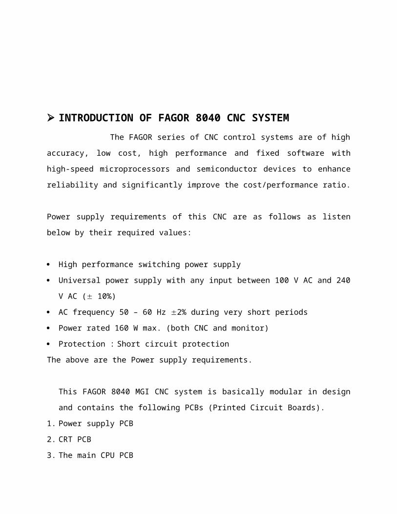
INTRODUCTION OF FAGOR 8040 CNC SYSTEM
The FAGOR series of CNC control systems are of high accuracy, low cost, high
performance and fixed software with high-speed microprocessors and semiconductor devices
to enhance reliability and significantly improve the cost/performance ratio.
Power supply requirements of this CNC are as follows as listen below by their required values:
High performance switching power supply
Universal power supply with any input between 100 V AC and 240 V AC ( 10%)
AC frequency 50 – 60 Hz 2% during very short periods
Power rated 160 W max. (both CNC and monitor)
Protection : Short circuit protection
The above are the Power supply requirements.
This FAGOR 8040 MGI CNC system is basically modular in design and contains the following
PCBs (Printed Circuit Boards).
1. Power supply PCB
2. CRT PCB
3. The main CPU PCB
4. Input/output PCB
5. Feedback adaptor PCB
6. Keyboard
7. Dynamic graphics board (Optional)

TECHNICAL SPECIFICATIONS OF THE FAGOR8040:
General characteristics:
4 feedback inputs for the axes.
4 analog outputs to control the axes (±10 V).
1 feedback input for the spindle encoder.
1 analog output to control the spindle (±10 V).
2 feedback inputs for the electronic handwheels.
2 inputs for digital probes (TTL or 24 Vdc)
0.0001mm or 0.00001 inch resolution.
Multiplying factor up to x 25 with sinewave input.
Feedrate from 0.0001 to 99999.9999 mm/min (0.00001 - 3937 inches/min).
Maximum travel: ±99999.9999 mm (±3937 inches).
1 RS232C communication line.
56 optocoupled digital inputs
32 optocoupled digital outputs
Remote modules for digital I/O expansion.
32-bit processor
Math coprocessor
Graphics coprocessor.
1Mb CNC program memory.
Block processing time of 6.5 ms.
Configurable sample time: 2, 3, 4, 5 or 6 ms.
Approximate weight 7.5 Kg.
Maximum consumption of 60 W in normal operation.
Color monitor:
Technology: Color TFT LCD.
Diagonal display area dimension: 10,4”.
Resolution: VGA 3 x 640 x 480 pixels.
Number of colors: 262144 Colors (6 bit for each subpixel RGB).
Backlit with 2 cold-cathode fluorescent lamps.
Monochrome monitor:
Technology: LCD STN.
Diagonal display area dimension: 10,4”.
Resolution: 640 x 480 pixels.
8 grey ranges.
Backlit with 1 cold-cathode fluorescent lamp.
Power supply:
Nominal voltage: 20 V minimum and 30 V maximum.
Ripple: 4 V.
Nominal current: 2 A.
Current peak on power-up: 8 A.
The figure shows the shape of the supply current on power-up
PLC
Memory: 100 kbytes.
Programming in mnemonics.
1 millisecond time unit.
512 inputs.
512 outputs.
2047 user marks.
256 32-bit registers.

256 32-bit counters.
256 32-bit timers.
5V probe input.
Typical value 0.25 mA. ≅ Vin = 5V.
High threshold (logic level 1) VIH: from +2.4 Vdc up.
Low threshold (logic level 0) VIL: Below +0.9 Vdc
Maximum nominal voltage Vimax = +15 Vcc.
24V probe input.
Typical value 0.30 mA. ≅ Vin = 24V.
High threshold (logic level 1) VIH: from +12.5 Vdc up.
Low threshold (logic level 0) VIL: Below +4 Vdc
Maximum nominal voltage Vimax = +35 Vcc.
Digital inputs
Nominal voltage + 24 Vdc.
Maximum nominal voltage + 30 Vdc.
Minimum nominal voltage + 18 Vdc.
High threshold (logic level 1) VIH: from +18 Vdc up.
Low threshold (logic level 0) VIL: Under +5 Vdc or not connected.
Typical consumption of each input 5 mA.
Maximum consumption of each input 7 mA.
Protection by means of galvanic isolation by optocouplers.
Protection against reverse connection up to -30 Vdc.
Digital outputs
Nominal supply voltage + 24 Vdc.
Maximum nominal voltage + 30 Vdc.
Minimum nominal voltage + 18 Vdc.
Output voltage Vout = Supply voltage (Vdc) -3 V
Maximum output current 100 mA

Protection by means of galvanic isolation by optocouplers.
Shortcircuit protection. Place external recovery diodes.
Feedback input for the axes and spindle
Power supply consumption of +5 V 1 A (250 mA per axis or spindle).
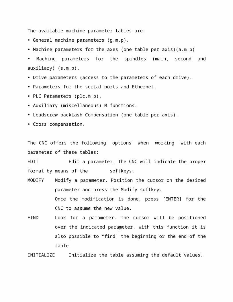
MACHINE PARAMETERS:
There are various machine parameters which are created in the memory card of CNC in
the form of tables.
The available machine parameter tables are:
• General machine parameters (g.m.p).
• Machine parameters for the axes (one table per axis)(a.m.p)
• Machine parameters for the spindles (main, second and auxiliary) (s.m.p).
• Drive parameters (access to the parameters of each drive).
• Parameters for the serial ports and Ethernet.
• PLC Parameters (plc.m.p).
• Auxiliary (miscellaneous) M functions.
• Leadscrew backlash Compensation (one table per axis).
• Cross compensation.
The CNC offers the following options when working with each parameter of these tables:
EDIT Edit a parameter. The CNC will indicate the proper format by means of the
softkeys.
MODIFY Modify a parameter. Position the cursor on the desired parameter and press the
Modify softkey.
Once the modification is done, press [ENTER] for the CNC to assume the new
value.
FIND Look for a parameter. The cursor will be positioned over the indicated
parameter. With this function it is also possible to “find” the beginning or the
end of the table.
INITIALIZE Initialize the table assuming the default values.
LOAD Load into memory the tables saved in the memkey card (CARD A), a peripheral
device or a PC.
SAVE Save the tables into the memkey card" (CARD A), a peripheral device or a PC.
MM/INCHES See the parameter values in the desired units. Only those parameters affected
by this conversion will be altered. It will not change the g.m.p. INCHES (P8) that
indicates machine units.
AXES AND COORDINATE SYSTEM:
The objective of the CNC is to control the movement and positioning of axes, it is
necessary to determine the position of the point to be reached through the coordinates.
The CNC allows you to use absolute, relative or incremental coordinates throughout the same
program.
Axis nomenclature:

Characteristics of the system of axes:
X and Y main movements on the main work plane of the machine.
Z parallel to the main axis of the machine, perpendicular to the main XY plane.
U, V, W auxiliary axes parallel to X, Y, Z respectively.
A, B, C Rotary axes on each axis X, Y, Z.
FAGOR 8040 MODULE STRUCTURE: INSTRUCTION SET
The modules which make up the PLC program (main module "PRG", periodic modules "PE" and
first cycle module "CY1") consist of a series of instructions which, depending on their
functionality, can be divided into:
• Directing instructions.
• Executable instructions.
Directing instructions provide the PLC with information on the type of module (PRG,
CY1,...) and on how it must execute it.
Executable instructions allow inquiries to be made on and/or alterations to the status of
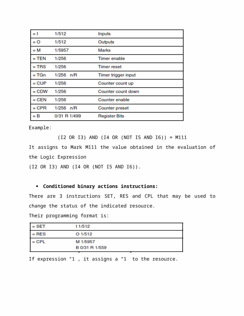
PLC resources and consist of:
Logic expressions (Boolean 0/1) I28 AND I30
Action instructions. = O25
Logic expressions consist of:
Consulting instructions I28, O25
Operators. AND
All comments must begin with a “;”: ;". The lines that begin with the “;” character are
considered as a comment and are not executed.

Directing instructions:
These provide the PLC with information on the type of module and the way it must be
executed. The directing instructions available at the PLC are:
PRG, PEt, CY1:
Define the module type.
PRG Main module.
CY1 First cycle module.
PE Periodic module.
END:
Indicates the end of the module. If this is not defined, the PLC understands that this
module ends in the last block of the program.
Example of programming using the directing instruction END:
CY1 Beginning of module CY1.
——-
END End of module CY1.
PRG Beginning of module PRG.
——-
END End of module PRG.
PE 100 Beginning of module PE.
——-
END End of module PE.
L:
Label. Used to identify a program line, and is only used when references or program jumps are
made. It will be represented with the letter L followed by three figures (1-256. If there are 2 or
more labels with the same number in a single program, the PLC will show the corresponding
error when compiling it.

DEF:
Symbol definition. Allows a symbol to be associated with any PLC variable, it being possible to
reference this variable throughout the program by means of the variable name or by means of
the associated symbol.
Example:
DEF EMERG I1
Assigns the EMERG symbol to input 11, so any reference throughout the program
to EMERG will be interpreted by the PLC as a reference to I1.
REA, IMA:
Indicate to the PLC that the consultations defined below will be made on the real (REA) or
image (IMA) values of I, O, M resources. Counters, timers and registers do not have image
values, so their real values will always be evaluated. Action instructions (=O32) will always
update the real values of PLC resources.
Example:
IMA
Consultations will evaluate image values.
I1 AND I2 = 01
---------
REA
Consultations will evaluate real values.
IMA I3 AND REA M4 = 02
Evaluates the image of I3 and the real of M4.
IMA I5 REA = O3
Evaluates the image of I5 and the next ones in real.
IRD/IREMRD:
Update the real values of the local inputs (IRD) and the remote ones (IREMRD) after reading the
relevant physical inputs.

Care must be taken when using these instructions since the current real values of the inputs will
be lost.
OWR/OREMWR:
Update the local physical outputs (OWR) and the remote ones (OREMWR) with the current real
values of the corresponding O resources.
MRD:
Updates the values of resources M5000/5957 and R500/559 with the values of the logic
outputs of the CNC.
Care must be taken when using this instruction since the current values of those resources will
be lost. After executing this instruction, the new values will match those of the logic outputs of
the CNC (internal variables).
MWR:
Updates the logic inputs of the CNC (internal variables) with the current real values of resources
M5000/5957 and R500/559.
Consulting instructions:
They are used to evaluate the PLC resources as well as the marks and registers of the CNC-PLC
communication.
These instructions are divided into:
• Simple consulting Instructions.
• Flank detection consulting Instructions.
• Comparison consulting Instructions.
SIMPLE:
They test the status of the resources and return their logic state.
Example:
I12 It will return a 1 if input 12 is active and a 0 if otherwise.
FLANK DETECTION:
They check if the status of the resource has changed since the last time this consultation was
made. This consultation may be made on real or image values.
There are two types of instructions:
DFU:
Detects whether an Up Flank (leading edge), a change of status from 0 to 1 has been
produced in the specified variable. It will return a “1” if that is the case.
DFD:
Detects whether a Down Flank (trailing edge), a change of status from 1 to 0 has been
produced in the specified variable. It will return a “1” if that is the case.
The programming format of the different combinations is:
Examples:
DFU I23
DFU B3R120
DFU AUXEND
COMPARISON:

CPS:
Used to compare two operands, checking whether the first one is greater than (GT), greater
than or equal to (GE), equal to (EQ), not equal to (NE), smaller than or equal to (LE) or less than
(LT) the second one.
The following may be used as operands:
Timers (internal count), Counters (internal count), Registers, CNC-PLC communication registers
and numbers (#) within ±2147483647 or between 0 and $FFFFFFFF.
The programming format of the different combinations is:
If the required condition is met, the consulting instruction will return the logic value “1”;
otherwise, value “0” is returned.
Programming examples:
CPS C12 GT R14 = M100
If the internal count of counter C12 is GREATER than the value of register R14, the PLC will
make M100 = 1 and M100=0 in the opposite case.
Operators and symbols:
Used to group and operate with different consulting instructions.
The available operators are: NOT AND OR XOR
The available symbols are: ( )
Operators are associated from left to right and the priorities, ordered from highest to lowest,
are the following:
NOT AND XOR OR
The “(“ and “)” signs are used to clarify and select the order (sequence) used to evaluate the
logic expression.

Example: (I2 OR I3) AND (I4 OR (NOT I5 AND I6)) = O7
ACTION INSTRUTIONS:
The action instructions, depending on the result obtained in the logic expression may be
used to alter the status of the PLC resources and CNC-PLC communication marks.
Logic expression = Action instruction
There may be several action instructions associated with a single logic expression. All
the action instructions must be preceded by the “=” sign.
Action instructions are divided into:
Assignment Binary Action Instructions.
Conditioned binary actions instructions.
Sequence breaking action instructions.
Arithmetic action instructions.
Logic action instructions.
Specific action instructions.
Binary assignment instructions:
They assign the value obtained from evaluating the logic expression (0/1) to the indicated
resource.

Example:
(I2 OR I3) AND (I4 OR (NOT I5 AND I6)) = M111
It assigns to Mark M111 the value obtained in the evaluation of the Logic Expression
(I2 OR I3) AND (I4 OR (NOT I5 AND I6)).
Conditioned binary actions instructions:
There are 3 instructions SET, RES and CPL that may be used to change the status of the
indicated resource.
Their programming format is:
If expression “1”, it assigns a “1” to the resource.
If the result of evaluating the logic expression is a “1”, it assigns a “1” to the indicated resource.
If the result is a “0”, it does not change the resource.
= SET
Example: CPS T2 EQ 100 = SET B0R100
When time elapsed in the timer T2 equals 100, bit 0 of register R100 will be set to 1.

= RES
Example: I12 OR NOT I22 = RES M55 = NOT RES M65
When the result of the logic expression is a “1”, the PLC sets “M55=0” and does not change
M65.
When the result of the logic expression is a “0”, the PLC sets “M65=0” and does not change
M55.
= CPL
Example: DFU I8 OR DFD M22 = CPL B12R35
Every time an Up Flank (leading edge) is detected at input I8 or a down flank (trailing edge) in
mark M22 the PLC will complement the status of bit 12 of register R35.
Sequence breaking action instructions:
These actions interrupt the sequence of a program and it continues somewhere else in the
program. That area must be identified with a label (L 1/256). A subroutine is any part of the
program that starts with a label (L1/256) and end with the directing instruction END.
= JMP Unconditional Jump.
If the result of evaluating the logic expression is a “1”, it causes jump to the indicated label. If
the result is a “0”, it goes on to the next line in the program.
Example:
I8 = JMP L12 If I8 = 1 it goes on to L12
= CAL Call to a subroutine.
If the result obtained in the evaluation of the logic expression is a “1” this action will execute
the indicated subroutine.
Example:
I2 = CAL L5 = O2
If I2=1, it will execute subroutine L5 and when done, the PLC sets output O2 to the value of
input I2 (1).
If I2=0, it does not execute the subroutine and the PLC sets output O2 to the value of input I2
(0).
= RET Return or end of subroutine.
If the result obtained in the evaluation of the logic expression is a “1” this action will be treated
by the PLC as if it involved the directing instruction END. If the result is a “0”, it will be ignored
by the PLC. If while executing a subroutine, the PLC detects a validated RET, it will end the
subroutine.
Arithmetic action instructions:
= MOV Used to move information from one PLC resource to another.
The source and destination codes indicate the original and destination format (binary or BCD) of
the data. 4, 8, 12, 16, 20, 24, 28 or 32 bits may be transmitted.
The programming format is:
= NGU Complements the bits of a register.
It complements all 32 bits of the register (changes the state of each bit).
Example:

I15 = NGU R152
If the input I15 has a value of “1” the PLC negates the 32 bits of register R152.
= NGS Register sign change.
Example:
I16 = NGS R89
If the input I16 has a value of “1” the PLC changes the sign of the contents of register R89.
= ADS, = SBS, = DVS, = MDS:
They may be used to carry out arithmetic operations such as addition (ADS), subtraction (SBS),
multiplication (MLS), division (DVS) and module or remainder of a division (MDS).
Example:
() = ADS R100 R101 R102 R102 = 1234 + 100 = 1334
() = ADS 1563 R101 R112 R112 = 1563 + 100 = 1663
Logic action instructions:
= AND, = OR, = XOR:
They may be used to carry out logic operations AND, OR and XOR between the contents of
registers or between a number an a register content. The result will always be placed in a
register.
Example:
()=AND R200 R201 R202 R202=B0 M2003=1
()=OR R200 R201 R203 R203=B11010111 M2003=0
= RR, = RL:
Used to rotate registers clockwise (RR) or counter-clockwise (RL). There are two types of
rotations: type 1 (RR1 or RL1) and type 2 (RR2 or RL2).

Type 1 rotation (RL1 or RR1):
It enters a 0 in the least significant bit (RL1) or in the most significant bit (RR1), by shifting the
remaining bits in the register. The value of the last bit disappears.
Type 2 rotation (RL2 or RR2)
Rollover rotation of the register in the indicated direction.
Specific action instructions:
= ERA:
Used to delete a group of resources. Indicate the first and last resource to be deleted. If a
group of timers is erased this is the equivalent of Resetting them and if a group of counters is
erased this is similar to making a preset with a value 0 for them. This action is especially
appropriate for execution in the first cycle module (CY1) with the aim of setting the required
resources in the initial working conditions.
Examples:
I12 = ERA O5 12

If input I12 has a value of “1” the PLC will set to 0 outputs O5 thru O12.
= CNCRD, = CNCWR:
Access to the internal CNC variables. They may be used to read (CNCRD) and write (CNCWR)
internal CNC variables and their programming format is:
CNCRD (Variable, Register, Mark)
CNCWR (Register, Variable, Mark)
The CNCRD action loads the contents of the variable into the register and the CNCWR action
reads the contents of the register into the variable.
Examples:
CNCRD (FEED, R150, M200)
Loads into register R150 the feedrate value selected at the CNC by means
of function G94.
= PAR:
It checks the parity type of a register. If the register being checked has an EVEN parity, this
instruction will set the indicated mark to “1” and if its parity is ODD, it will set it to “0”.
Example:
I15 = PAR R123 M222
If I15 = 1 the PLC checks the parity of register R123 and sets M222 = 1 if itis EVEN or M222 = 0 if
it is ODD.
LOGIC CNC INPUTS AND OUTPUTS:
Physical inputs and outputs are the names given to the set of inputs and outputs of the CNC
system which, being controlled by the PLC, communicate with the outside through CNC
connectors.
The CNC also has a series of logic inputs and outputs for the internal exchange of information
with PLC marks and registers. This type of marks does not have images on the PLC.

Each of these CNC logic inputs and outputs may be referred to with the corresponding PLC
resource or with their associated mnemonic. Mnemonics which begin with “/” indicate that the
signal is active low (0 V). For example:
M5000 /EMERGEN M5104 MIRROR1
M5016 AUXEND M5507 /ALARM
All the mnemonics refer to their associated variable, it being necessary to use the
NOT operator to refer to its negation, for example:
NOT M5000 NOT /EMERGEN
NOT M5016 NOT AUXEND
CNC logic inputs and outputs can be grouped in:
General logic inputs .
Axis logic inputs.
Spindle logic inputs.
Logic inputs of the auxiliary spindle
Key inhibiting logic inputs.
Logic inputs of the PLC channel
General logic outputs.
Axis logic outputs.
Spindle logic outputs.
Logic outputs of the auxiliary spindle
Logic outputs of key status
Logic inputs of the PLC channel
General logic inputs:
/EMERGEN (M5000):
There are two ways to cause an emergency at the CNC, by activating the physical input
/Emergency stop (pin 10 of connector X2) or the general logic input “/EMERGEN” from the PLC.

When the PLC sets the "/EMERGEN" input low (0V), the CNC stops the axes and the spindle and
it displays the corresponding error message. Also, the CNC activates the "/EMERGENCY
OUTPUT" and "/ALARM" signals to let the outside world and the PLC know that an emergency
has occurred at the CNC.
The CNC does not allow executing programs and it aborts any attempt to move the axes or the
spindle while the "/EMERGEN" input is low (0V). When the PLC brings the "/EMERGEN" input
back high (24V), the CNC deactivates the "/EMERGENCY OUTPUT" and "/ALARM" signals.
Example;
I-EMERG AND (rest of conditions) = /EMERGEN
If the external emergency input is activated or any other emergency occurs, the general logic
input /EMERGEN of the CNC. When there is no emergency, this signal must remain high.
/STOP (M5001):
When the PLC sets this signal low, the CNC stops the part program, and maintains spindle
rotation. In order to continue executing the program, as well as setting this signal at a high logic
level, the general logic input CYSTART must be activated.
Example
( ) = /STOP
There is always permission to execute the part program.
/FEEDHOL (M5002)
When the PLC sets this signal low, the CNC stops the axes (maintaining spindle rotation). When
the signal returns to the high logic level, the movement of the axes continues.
If the /FEEDHOL signal is activated (0V) in a block without motion, the CNC will continue the
execution of the program until detecting a block with motion.
Example:
() = /FEEDHOL
There is always permission to move the axes.
Axis logic inputs:
There are several groups of logic inputs (LIMIT, DECEL, etc.) which refer to the possible axes of
the machine by means of digits 1 through 4 (LIMIT+2, DECEL1,etc.) or using the axis name
(LIMIT+X, DECELZ, etc.).
LIMIT+1 (M5100) | LIMIT-1 (M5101)
LIMIT+2 (M5150) | LIMIT-2 (M5151) :
LIMIT+3 (M5200) | LIMIT-3 (M5201)
LIMIT+4 (M5250) | LIMIT-4 (M5251)
The PLC sets these signals at a high logic level in order to tell the CNC that the corresponding
axis has overrun the end of its range of movement in the positive (+) or negative (-) direction
indicated by the limit switch.
In this case, the CNC stops axis feed and spindle rotation and displays the corresponding error
on screen. In manual (JOG) operating mode the axis which has overrun its range of travel can be
moved in the correct direction in order to place it within the correct range of travel.
DECEL1 (M5102) DECEL2 (M5152) DECEL3 (M5202) DECEL4 (M5252):
These signals are used by the CNC when machine reference search is made. If the PLC sets one
of these signals high, this indicates to the CNC that the machine reference search switch of the
corresponding axis has been pressed.
AXIS+1 (M5108) | AXIS-1 (M5109)
AXIS+2 (M5158) | AXIS-2 (M5159):
AXIS+3 (M5208) | AXIS-3 (M5209)
AXIS+4 (M5258) | AXIS-4 (M5259)
The CNC uses these signals when working in the manual (JOG) operating mode. If the PLC sets
one of these signals high, the CNC will move the corresponding axis in the direction indicated,
positive (+) or negative (-). This movement will be performed at the feedrate override %
currently selected.

Spindle logic inputs:
This CNC can handle 2 spindles: a main spindle and a second spindle. They both can be
operative simultaneously, but only one can be controlled at a time. This selection can be made
via part-program by means of functions G28 and G29.
LIMIT+S (M5450) | LIMIT-S (M5451) main spindle:
LIMIT+S2 (M5475) | LIMIT-S2 (M5476) Second spindle:
The CNC uses this signal while searching home when the spindle changes to working in closed
loop (M19). The CNC only considers the signals for the currently selected spindle. The PLC sets
one of the signals high to tell the CNC that the spindle has overrun its range of travel in the
positive (+) or negative (-) direction. In this case, the CNC stops axis feed and spindle rotation
and displays the corresponding error on screen.
DECELS (M5452) Main spindle:
DECELS2 (M5477) Second spindle:
The CNC uses this signal while searching home when the spindle changes to working in closed
loop (M19). The CNC only considers the signals for the currently selected spindle. The PLC sets
this signal high to indicate to the CNC that the reference search switch is pressed.
Logic inputs of the PLC channel:
/FEEDHOP (M5004):
It is similar to general logic input /FEEDHOL (M5002), but for the PLC channel. When the PLC
sets this signal low, the CNC stops the axes (maintaining spindle rotation). When the signal
returns to the high logic level, the movement of the PLC axes continues. This input must always
be defined in the PLC program.
General logic outputs:
CNCREADY (M5500):

The CNC activates and maintains this signal high if the autotest which the CNC makes when it is
powered up has not detected any problem. If any hardware error be detected (RAM, over-
temperature, etc.) this signal is set low.
START (M5501):
The CNC sets this signal high in order to tell the PLC that the START key on the front panel has
been pressed. If the PLC program considers that there is nothing to prevent the part program
from starting, it must set the general logic input CYSTART at a high logic level, thereby starting
the execution of the program. When the CNC detects an up flank (logic level change from low
to high) at the CYSTART signal, it reset the START signal to low.
Example:
START AND (rest of conditions) = CYSTART
When the cycle START key is pressed, the CNC activates the general logic output START.
FHOUT (M5502):
The CNC sets this signal high in order to tell the PLC that the execution of the program is
stopped due to one of the following causes:
• Because the CONTROL PANEL STOP key has been pressed.
• Because the general logic input /STOP has been set low, even though later it has returned
high.
• Because the general logic input /FEEDHOL is low.
RESETOUT (M5503):
The CNC sets this signal high for 100 milliseconds, in order to tell the PLC that it is under initial
conditions because the Reset key on the front panel has been pressed or because the general
logic input RESETIN has been activated.
LOPEN (M5506):

The CNC sets this signal high in order to tell the PLC that the positioning loop of the axes is open
since an error has occurred.
/ALARM (M5507):
The CNC sets this signal low in order to tell the PLC that an alarm or emergency condition has
been detected. This signal will be set high once again, once the message from the CNC has been
eliminated and the cause of the alarm has disappeared. Likewise, while this signal is low, the
CNC keeps the emergency output (pin 2 of connector X2) active (low).
Example:
/ALARM AND (other conditions) = O1
The emergency output O1 of the PLC must be normally high. If an alarm or an emergency is
detected at the CNC, the emergency output O1 must be set low (0V).
MANUAL (M5508):
The CNC sets this signal high to tell the PLC that the JOG (Manual) operating mode is selected.
AUTOMAT (M5509):
The CNC sets this signal high to tell the PLC that the automatic operating mode is selected.

MDI (M5510):
The CNC sets this signal high to tell the PLC that the MDI mode (manual data input) is selected
in one of the operating modes (JOG, automatic, etc.).
SBOUT (M5511):
The CNC sets this signal high to tell the PLC that the single block execution mode is selected.
Related Documents


