WAAB 600 A ti hill d b idth 600 Active chilled beam – width 600 MADEL The WAAB-600 chilled beam is an air/water induction terminal unit that simultaneously provides the supply, thermal treatment and diffusion of supply air, to set internal conditions at the desired comfort levels. Chilled beams take advantage of the excellent thermal properties of water to guarantee optimal comfort levels, with minimal power consumption. The main heat-transferring component in the WAAB-600 chilled beam is a battery formed by copper The main heat-transferring component in the WAAB-600 chilled beam is a battery, formed by copper tubing and aluminium blades. It also incorporates air ducts and a plenum for supplying the ventilation air, which has been pre-treated in a central air conditioning unit. The WAAB-600 chilled beam can be supplied with connections on the side or on the top, for both supply air and return air. The unit can be adapted to modular ceilings measuring 600x600, 625x625 and 675x675 for T24 and T15 profiles. Thanks to its reduced size, it can also be installed in low-hanging false ceilings. 1 01/14

Welcome message from author
This document is posted to help you gain knowledge. Please leave a comment to let me know what you think about it! Share it to your friends and learn new things together.
Transcript

WAAB 600A ti hill d b idth 600Active chilled beam – width 600
MADEL!
The WAAB-600 chilled beam is an air/water induction terminal unit that simultaneously provides the
supply, thermal treatment and diffusion of supply air, to set internal conditions at the desired comfort
levels. Chilled beams take advantage of the excellent thermal properties of water to guarantee optimal
comfort levels, with minimal power consumption.
The main heat-transferring component in the WAAB-600 chilled beam is a battery formed by copperThe main heat-transferring component in the WAAB-600 chilled beam is a battery, formed by copper
tubing and aluminium blades. It also incorporates air ducts and a plenum for supplying the ventilation
air, which has been pre-treated in a central air conditioning unit. The WAAB-600 chilled beam can be
supplied with connections on the side or on the top, for both supply air and return air.
The unit can be adapted to modular ceilings measuring 600x600, 625x625 and 675x675 for T24 and
T15 profiles. Thanks to its reduced size, it can also be installed in low-hanging false ceilings.
1 01/14

CLASSIFICATION
WAAB-600 WAAB-600 Beam for supply air.
/2T/ 2 t b b tt…/2T/ 2-tube battery
…/4T/ 4-tube battery.
…/LD/ Right side connection.
…/LI/ Left side connection.
…/S/ Top connection.
…/ / Standard support
…/T15/ Support for dropped panel, 15-mm
profile modular ceilings.
/T24/ Support for dropped panel 24 mm
31 2
4
56
1.-Air input neck
2.-Plenum
3.-Anchoring point for fixing
4.-Nozzles
5.-Adjustable deflector
6.-Collapsible front panel
…/T24/ Support for dropped panel, 24-mm
profile modular ceilings.
…/KS/ Small discharge nozzles.
…/KM/ Medium discharge nozzles.
…/KL/ Large discharge nozzles.
…/FC/ Front panel with circular perforations.
…/FQ/ Front panel with square perforations
/FL/ Front panel with lineal aluminium grill
WAAB-600/…/…/L/… WAAB-600/…/…/S/…
WAAB-600/2T/… WAAB-600/4T/…
56
…/FL/ Front panel with lineal aluminium grill.
…/TY/ Type (see pages 5,6 and 7)
ACCESORIES
DEF Deflecting blades (see page 4)
MOUNT
(D) Angle bracket for suspending from ceiling
(see page 8)(see page 8)
FINISH
M9016 Lacquered white similar to RAL 9016
R9010 Lacquered white RAL 9010
RAL… Lacquered other colours RAL
MATERIAL
Galvanised steel body, ABS plastic deflective
…/FC/ …/FQ/ …/FL/
Ga a sed stee body, S p ast c de ect e
blades and battery with copper tubing and
aluminium blades.
The tubes connected to the battery have a
diameter of 12 mm and a thickness of 1mm,
in fulfilment of the EN 1057:1996 European
Standard. The battery’s maximum working
pressure is 1 MPa.
…/T15/ …/T24/
W/ / T15 T24
W1
W2 9 W1 8
…/ /
p
SPECIFICATION TEXT
S l d i t ll ti f ti hill d b f l i d t i ith 4 t b b tt i ht
WN
W1 W1 W2 W1 W2
600 595 595 579 595 571
625 620 620 604 620 596
675 670 670 654 670 646
Supply and installation of active chilled beam for supply air and return air, with 4-tube battery, right
side connection plenum, pre-set medium nozzles, circular perforated front panel, type LDR1, with
deflective blades, WAAB-600 / 4T / LD / KM / FC / LDR1 1195x900 /+ DEF
Built in lacquered white galvanised steel R9010.
Brand MADEL.
2 01/14

CONSTRUCTION AND WORKING SYSTEM WAAB 600
The ventilation air is injected through nozzles that cause the air to accelerate and force air induction in
the room, through the battery. Subsequently, the two masses of air (the induced air and ventilation air)
are supplied to the space that requires air-conditioning.
Primary air
Induced air
The WAAB 600 has been designed so that it can be accessed easily for maintenance and servicing
operations. For this, it has 4 fastening hinges, which keep the internal frame in position. Thus, the
internal frame is collapsible over two axes, by simply moving the two hinges situated on the same face
as the internal frame. In this way, both the battery and the primary airflow regulating systems are
easily accessible for any necessary maintenance and adjustment operations Plus once the internaleasily accessible for any necessary maintenance and adjustment operations. Plus, once the internal
frame has been collapsed over one of its axes, the internal frame can be completely removed by
moving the two remaining hinges.
Once the internal frame of the WAAB 600 chilled beam has been released, the airflow can be adjusted
and the deflection angle changed.a d t e de ect o a g e c a ged
3 01/14
CONSTRUCTION AND WORKING SYSTEM WAAB 600
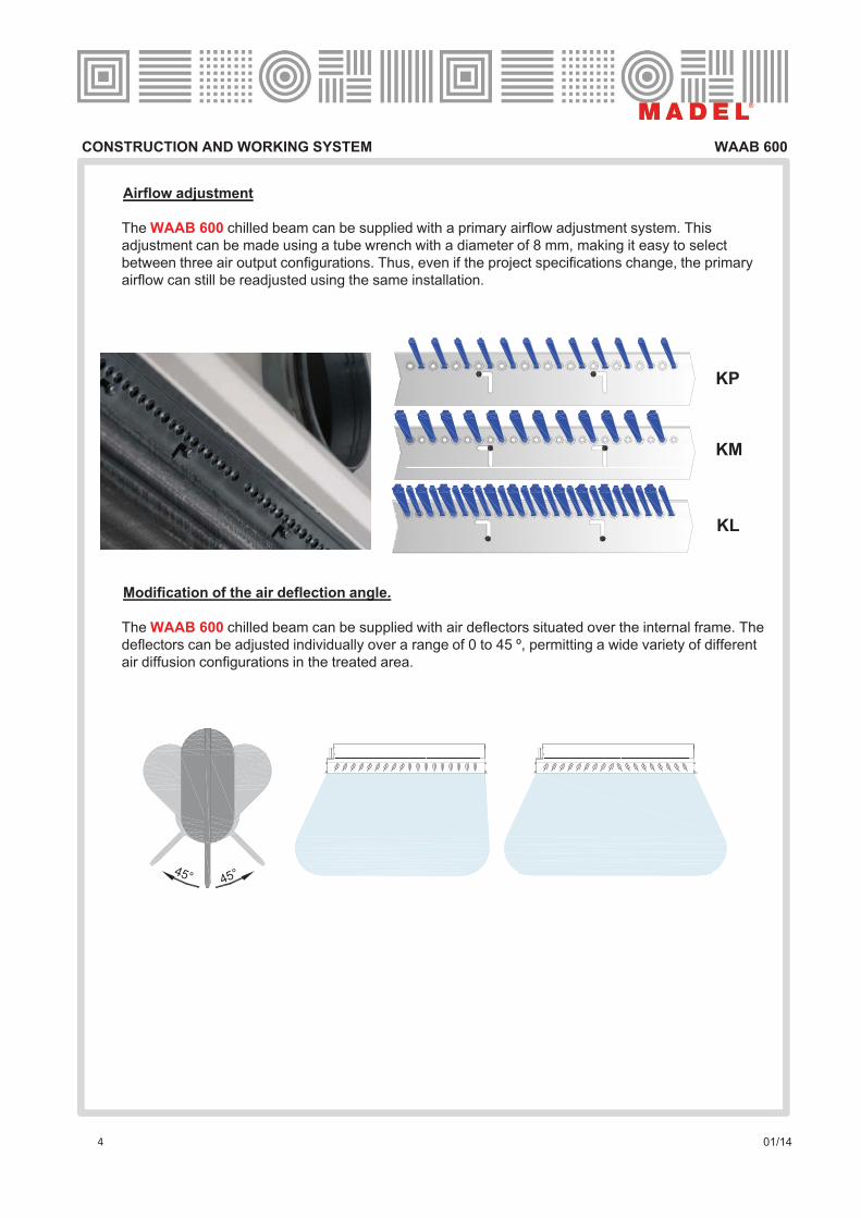
Airflow adjustment
The WAAB 600 chilled beam can be supplied with a primary airflow adjustment system. This
adjustment can be made using a tube wrench with a diameter of 8 mm, making it easy to select
between three air output configurations. Thus, even if the project specifications change, the primary
airflow can still be readjusted using the same installation.
KP
KM
Modification of the air deflection angle.
KL
The WAAB 600 chilled beam can be supplied with air deflectors situated over the internal frame. The
deflectors can be adjusted individually over a range of 0 to 45 º, permitting a wide variety of different
air diffusion configurations in the treated area.
45°45°
4 01/14
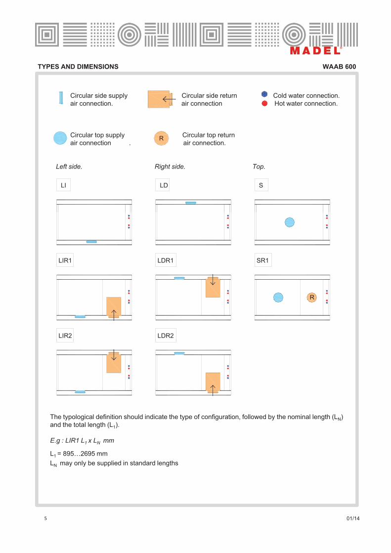
TYPES AND DIMENSIONS WAAB 600
Circular side supply Circular side return Cold water connection.
air connection. de air connection Hot water connection.
Circular top supply Circular top return
air connection . air connection.R
Left side. Right side. Top.
LI LD S
SR1LIR1 LDR1
LIR2 LDR2
R
The typological definition should indicate the type of configuration, followed by the nominal length (LN)
and the total length (L1).
E.g : LIR1 L1 x LN mm
L1 = 895…2695 mm
LN may only be supplied in standard lengths
5 01/14

TYPES AND DIMENSIONS WAAB 600
LI , LD ,S Configuration
LN = 900, 1200, 1500 and 1800 mm
162.5 162.5
D
A
B
LI , LD ,S Configuration
LN = 1800, 2100 and 2400 mm
C
162.5
A
B B
162.5
D
276.4276.4
C
L1
L2
A
B B
LIR1 , LIR2 , LDR1, LDR2 and SR1 Configuration
LN = 900, 1200, 1500 and 1800 mm LN = 1800, 2100 and 2400 mm
L1
L2
A
B
LIR1 , LIR2 , LDR1, LDR2 and SR1 Configuration
125
C 162.5 276.4 276.4 162.5
B B
L1
L2
D
L1
L2
162.5
B
162.5
C D
125
Configuration with side air connection Configuration with top air connection
406.8223.6
W8
Ø 125
406.8
W8
Ø125
210 210
1.- WAAB 600 dimensions table for LI, LD and S Configurations
W8 W8
min max min max min maxø (mm)
L 1 (mm)L
N(mm) W (mm)
L 2 (mm)A (mm) B (mm) D (mm)
C (mm)
LI , LD and S
895 2695 900 595 860 2660 788 394,0 18,5 71 1871 1-125
1195 2695 1200 595 1160 2660 1088 544,0 18,5 71 1571 1-125
1495 2695 1500 595 1460 2660 1388 694,0 18,5 71 1271 1-125
1795 2695 1800 595 1760 2660 1688 844,0 18,5 71 971 1-125
2095 2695 2100 595 2060 2660 1988 450 18,5 71 671 2-125
2395 2695 2400 595 2360 2660 2288 600 18,5 71 371 2-125
2695 2695 2700 595 2660 2660 2588 750 18,5 71 71 2-125
6 01/14

TYPES AND DIMENSIONS WAAB 600
2 - WAAB 600 dimensions table for LIR and LDR Configurations2.- WAAB 600 dimensions table for LIR and LDR Configurations.
min max min max min max
1195 2695 900 595 1160 2660 788 394,0 18,5 371 1871 1-125
1495 2695 1200 595 1460 2660 1088 544,0 18,5 371 1571 1-125
1795 2695 1500 595 1760 2660 1388 694,0 18,5 371 1271 1-125
2095 2695 1800 595 2060 2660 1688 844,0 18,5 371 971 1-125
2395 2695 2100 595 2360 2660 1988 450 18 5 371 671 2 125
LIR1 , LIR2 , LDR1 , LDR2 and SR1
ø (mm)L
1(mm)
LN (mm) W (mm)
L2
(mm)A (mm) B (mm) D (mm)
C (mm)
3.- WAAB 625 dimensions table for LI, LD and S Configurations
2395 2695 2100 595 2360 2660 1988 450 18,5 371 671 2-125
2695 2695 2400 595 2660 2660 2288 600 18,5 371 371 2-125
min max min max min max
932 2495 937 620 872 2435 788 394,0 31,0 83,0 1646,0 1-125
1245 2495 1250 620 1185 2435 1088 544 0 31 0 96 0 1346 0 1 125
ø (mm)
LI , LD and S
B (mm) D (mm)C (mm)L 1 (mm)
LN
(mm) W (mm)L 2 (mm)
A (mm)
4.- WAAB 625 dimensions table for LIR and LDR Configurations
1245 2495 1250 620 1185 2435 1088 544,0 31,0 96,0 1346,0 1-125
1557 2495 1562 620 1497 2435 1388 694,0 31,0 108,0 1046,0 1-125
1870 2495 1875 620 1810 2435 1688 844,0 31,0 121,0 746,0 1-125
2182 2495 2187 620 2122 2435 1988 450 31,0 133,0 446,0 2-125
2495 2495 2500 620 2435 2435 2288 600 31,0 146,0 146,0 2-125
LIR1 , LIR2 , LDR1 , LDR2 and SR1
L ( ) L ( ) C ( )
min max min max min max
1245 2495 937 620 1185 2435 788 394,0 31,0 396,0 1646,0 1-125
1557 2495 1250 620 1497 2435 1088 544,0 31,0 408,0 1346,0 1-125
1870 2495 1562 620 1810 2435 1388 694,0 31,0 421,0 1046,0 1-125
2182 2495 1875 620 2122 2435 1688 844,0 31,0 433,0 746,0 1-125
2495 2495 2187 620 2435 2435 1988 450 31,0 446,0 446,0 2-125
ø (mm)L
1(mm)
L N (mm) W (mm)L
2(mm)
A (mm) B (mm) D (mm)C (mm)
5.- WAAB 675 dimensions table for LI, LD and S Configurations
min max min max min max
1007 2695 1012 670 897 2585 788 394,0 56,0 108,0 1796,0 1-125
1345 2695 1350 670 1235 2585 1088 544,0 56,0 146,0 1496,0 1-125
1682 2695 1687 670 1572 2585 1388 694,0 56,0 183,0 1196,0 1-125
2020 2695 2025 670 1910 2585 1688 844,0 56,0 221,0 896,0 1-125
2357 2695 2362 670 2247 2585 1988 450 56,0 258,0 596,0 2-125
D (mm)C (mm)
ø (mm)
LI , LD and S
L 1 (mm)L
N(mm) W (mm)
L 2 (mm)A (mm) B (mm)
6.- WAAB 675 dimensions table for LIR and LDR Configurations
, , ,
2695 2695 2700 670 2585 2585 2288 600 56,0 296,0 296,0 2-125
min max min max min max
1345 2695 1012 670 1235 2585 788 394,0 56,0 446,0 1796,0 1-125
1682 2695 1350 670 1572 2585 1088 544 0 56 0 483 0 1496 0 1 125
ø (mm)
LIR1 , LIR2 , LDR1 , LDR2 and SR1
L1
(mm)L N (mm) W (mm)
L2
(mm)A (mm) B (mm) D (mm)
C (mm)
7 01/14
1682 2695 1350 670 1572 2585 1088 544,0 56,0 483,0 1496,0 1-125
2020 2695 1687 670 1910 2585 1388 694,0 56,0 521,0 1196,0 1-125
2357 2695 2025 670 2247 2585 1688 844,0 56,0 558,0 896,0 1-125
2695 2695 2362 670 2585 2585 1988 450 56,0 596,0 596,0 2-125

ASSEMBLY WAAB 600
Th WAAB 600 hill d b i t i f ti l b k t b th idThe WAAB 600 chilled beam incorporates a series of mounting angle brackets on both sides.
These brackets have an 18-mm long slot, so that the chilled beam can be easily mounted in the
installation. The number of brackets available varies depending on the nominal length of the
selected chilled beam; 4 for LN ! 1800 mm and 8 for LN " 2100 mm. The unit should be
suspended from the structure with officially approved steel supports, cables or rods. Once
suspended, the primary air duct should be connected to the plenum’s neck. Likewise, the battery
should be connected with solid elements, welding or quick connect fittings. Check that the
hydraulic circuit has been properly emptied and that the beam is properly connected to the
ventilation system to prevent air leaksventilation system to prevent air leaks.
18
mm
WAAB-…/ /WN
/ / T15 T24
W1 W1 W2 W1 W2
600 595 595 579 595 571
Ø 12Ø 12
W1 8
WAAB-…/ T15 /
600 595 595 579 595 571
625 620 620 604 620 596
675 670 670 654 670 646
W1
W2 9
WAAB-…/ T24 /
31.8
31.8
159
8 01/14
W1
W2 9
DEFINITIONS WAAB 600
D t i i th
X B
L
mwc!Ti,wc
To,wcTo,wh
mwh!Ti,wh
mpr!!Tpr
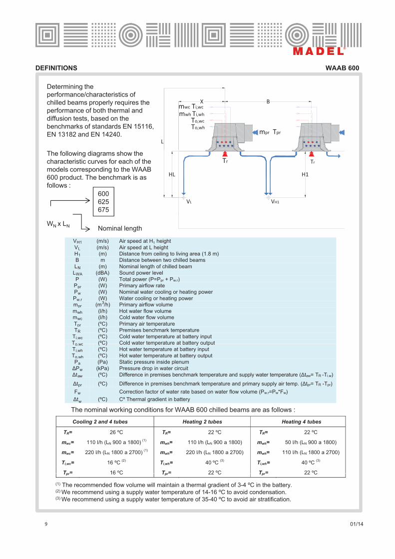
Determining the
performance/characteristics of
chilled beams properly requires the
performance of both thermal and
diffusion tests, based on the
benchmarks of standards EN 15116,
EN 13182 and EN 14240.
VL
H1
Tr
HL
VH1
Tr
The following diagrams show the
characteristic curves for each of the
models corresponding to the WAAB
600 product. The benchmark is as
follows :
600
625
675
WN x LN Nominal length
VH1 (m/s) Air speed at H1 height
VL (m/s) Air speed at L heightH1 (m) Distance from ceiling to living area (1.8 m)B m Distance between two chilled beams
LN (m) Nominal length of chilled beam
LWA (dBA) Sound power level
P (W) Total power (P=P + P )P (W) Total power (P=Ppr + Pw.r)Ppr (W) Primary airflow rate
Pw (W) Nominal water cooling or heating power
Pw,r (W) Water cooling or heating powermpr (m3/h) Primary airflow volume
mwh (l/h) Hot water flow volumemwc (l/h) Cold water flow volume
Tpr (ºC) Primary air temperature
TR (ºC) Premises benchmark temperature
Ti,wc (ºC) Cold water temperature at battery input
To wc (ºC) Cold water temperature at battery output
The nominal working conditions for WAAB 600 chilled beams are as follows :
To,wc ( C) Cold water temperature at battery output
Ti,wh (ºC) Hot water temperature at battery input
To,wh (ºC) Hot water temperature at battery output
Pa (Pa) Static pressure inside plenum
#Pw (kPa) Pressure drop in water circuit
#taw (ºC) Difference in premises benchmark temperature and supply water temperature (#taw= TR -Ti.w)
#tpr (ºC) Difference in premises benchmark temperature and primary supply air temp. (#tpr= TR -Tpr)
Fw Correction factor of water rate based on water flow volume (Pw.r=Pw*Fw)
#tw (ºC) Cº Thermal gradient in battery
The nominal working conditions for WAAB 600 chilled beams are as follows :
Cooling 2 and 4 tubes Heating 2 tubes Heating 4 tubes
TR= 26 ºC TR= 22 ºC TR= 22 ºC
mwc= 110 l/h (LN 900 a 1800)(1)
mwh= 110 l/h (LN 900 a 1800) mwh= 50 l/h (LN 900 a 1800)
mwc= 220 l/h (LN 1800 a 2700)(1)
mwh= 220 l/h (LN 1800 a 2700) mwh= 110 l/h (LN 1800 a 2700)
Ti,wc= 16 ºC(2)
Ti,wh= 40 ºC(3)
Ti,wh= 40 ºC(3)
Tpr= 16 ºC Tpr= 22 ºC Tpr= 22 ºC
9 01/14
(1) The recommended flow volume will maintain a thermal gradient of 3-4 ºC in the battery.(2) We recommend using a supply water temperature of 14-16 ºC to avoid condensation.(3) We recommend using a supply water temperature of 35-40 ºC to avoid air stratification.
Tpr 16 C Tpr 22 C Tpr 22 C
TECHNICAL DATA and METHODOLOGY WAAB 600
! " !#$ % !&
Methodology
A chilled beam’s capacity consists of one part supplied by the primary air and a second
part supplied by the water.
The primary air rate can be calculated using the Graphs numbered with II It can likewise
P = Ppr + Pw,r
!#$ " '() * +#$ * ,-$#
The primary air rate can be calculated using the Graphs numbered with II. It can likewise
be calculated using the following equation:
Because of the chilled beams’ high capacity in heating mode, it is not necessary for the
primary air to supply additional heat. In these cases, the system usually works with a
discharge of isothermal air, that is, by discharging the primary air at the same temperature
!& $ " !& * .&
g y g g p y p
as that in the premises (#tpr=0).
The technical data pertaining to each of the chilled beams are determined using the
following graphs. The graphs show that the water’s thermal capacity varies depending on
the water’s volume of flow. Thus, once we have defined the nominal thermal capacity (Pw),
we calculate the chilled beam’s working thermal capacity by applying the water flow
volume correction factor (Fw)
!&/$ !& .&
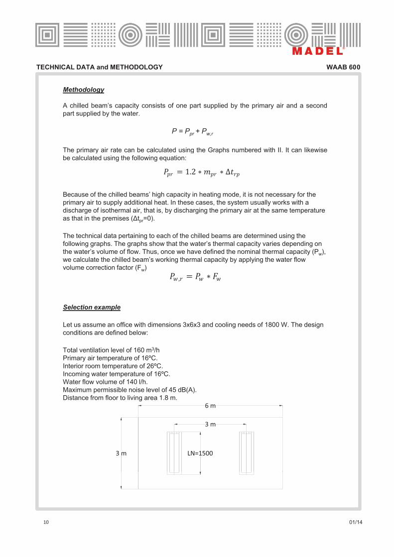
Selection example
Let us assume an office with dimensions 3x6x3 and cooling needs of 1800 W. The design
conditions are defined below:
6 m
Total ventilation level of 160 m3/h
Primary air temperature of 16ºC.
Interior room temperature of 26ºC.
Incoming water temperature of 16ºC.
Water flow volume of 140 l/h.
Maximum permissible noise level of 45 dB(A).
Distance from floor to living area 1.8 m.6!m
3!m
3!m LN=1500
10 01/14
TECHNICAL DATA and METHODOLOGY WAAB 300
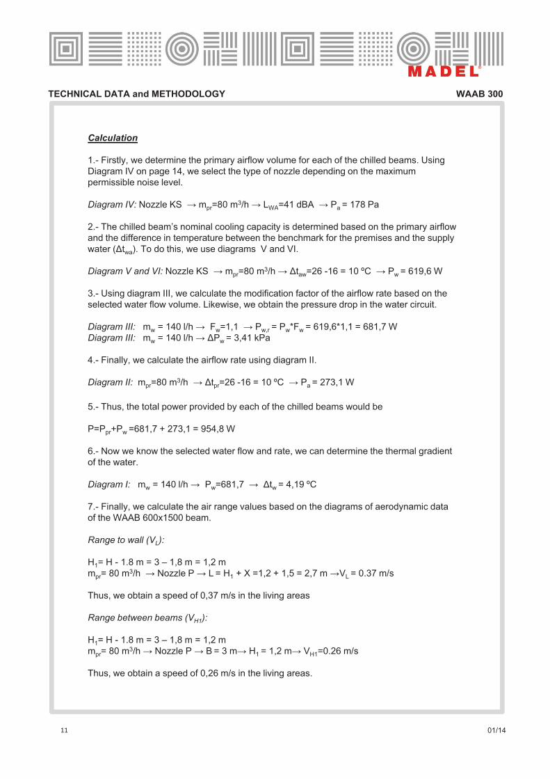
Calculation
1.- Firstly, we determine the primary airflow volume for each of the chilled beams. Using
Diagram IV on page 14, we select the type of nozzle depending on the maximum
permissible noise level.
Diagram IV: Nozzle KS $ mpr=80 m3/h $ LWA=41 dBA $ Pa = 178 Pag pr WA a
2.- The chilled beam’s nominal cooling capacity is determined based on the primary airflow
and the difference in temperature between the benchmark for the premises and the supply
water (#twa). To do this, we use diagrams V and VI.
Diagram V and VI: Nozzle KS $ mpr=80 m3/h $ #taw=26 -16 = 10 ºC $ Pw = 619,6 W
3.- Using diagram III, we calculate the modification factor of the airflow rate based on the
selected water flow volume. Likewise, we obtain the pressure drop in the water circuit.
Diagram III: mw = 140 l/h $ Fw=1,1 $ Pw,r = Pw*Fw = 619,6*1,1 = 681,7 W
Diagram III: mw = 140 l/h $ #Pw = 3,41 kPa
4.- Finally, we calculate the airflow rate using diagram II.
Diagram II: mpr=80 m3/h $ #tpr=26 -16 = 10 ºC $ Pa = 273,1 W
5.- Thus, the total power provided by each of the chilled beams would be
P=Ppr+Pw =681,7 + 273,1 = 954,8 W
6.- Now we know the selected water flow and rate, we can determine the thermal gradient
of the water.
Diagram I: mw = 140 l/h $ Pw=681,7 $ #tw = 4,19 ºC
7.- Finally, we calculate the air range values based on the diagrams of aerodynamic data
of the WAAB 600x1500 beam.
Range to wall (VL):
H1= H - 1.8 m = 3 – 1,8 m = 1,2 m3mpr= 80 m3/h $ Nozzle P $ L = H1 + X =1,2 + 1,5 = 2,7 m $VL = 0.37 m/s
Thus, we obtain a speed of 0,37 m/s in the living areas
Range between beams (VH1):
H1= H - 1.8 m = 3 – 1,8 m = 1,2 m
mpr= 80 m3/h $ Nozzle P $ B = 3 m$ H1 = 1,2 m$ VH1=0.26 m/s
11 01/14
Thus, we obtain a speed of 0,26 m/s in the living areas.
Related Documents
![MADEL WAAB SUITE EN [Modo de compatibilidad]](https://static.cupdf.com/doc/110x72/620a53dbed87612f3d1ff8ae/madel-waab-suite-en-modo-de-compatibilidad.jpg)


![MADEL DCG ES [Modo de compatibilidad]...DCG difusores circulares de conos regulables MADEL Los difusores de la serie DCG han sido diseñados para su aplicación en aire acondicionado,ventilación](https://static.cupdf.com/doc/110x72/5e48fc432aa80308643f201b/madel-dcg-es-modo-de-compatibilidad-dcg-difusores-circulares-de-conos-regulables.jpg)

