08-11-2020 Side 1 Madan Mohan Malaviya Univ. of Technology, Gorakhpur Prof. A. K. Sharma Department of Computer Science & Engineering Madan Mohan Malaviya University of Technology Gorakhpur, India Computer Graphics (BCS-27) L:T:P :: 3:1:2 (Credits: 5)

Welcome message from author
This document is posted to help you gain knowledge. Please leave a comment to let me know what you think about it! Share it to your friends and learn new things together.
Transcript
08-11-2020 Side 1
Madan Mohan Malaviya Univ. of Technology, Gorakhpur
Prof. A. K. Sharma
Department of Computer Science & Engineering
Madan Mohan Malaviya University of Technology
Gorakhpur, India
Computer Graphics (BCS-27)
L:T:P :: 3:1:2 (Credits: 5)

08-11-2020 Side 2
Madan Mohan Malaviya Univ. of Technology, Gorakhpur
Unit-1
Basics of Computer Graphics
Graphic Devices
Simple Line Drawing Methods

08-11-2020 Side 3
Madan Mohan Malaviya Univ. of Technology, Gorakhpur
Basics of Computer Graphics
➢ In computer graphics, we study tools and techniques for screen control
of the display unit attached with the computer.
➢ Screen control is done up to the level of having control over all pixel’s
attributes on the screen.
➢ Pixel refers to the smallest addressable unit of picture on the screen.
➢ Pixel’s attributes refers to the colour and intensity of the light output
from the pixel.
08-11-2020 Side 4
Madan Mohan Malaviya Univ. of Technology, Gorakhpur
Basics of Computer Graphics (contd…)
Interactive computer graphics involves two-way communication
between computer and user. The computer, upon receiving signals
from the input device, can modify the displayed picture appropriately.
To the user it appears that the picture is changing instantaneously in
response to his commands.
Major application areas of computer graphics includes
1. Computer Aided Design/ Drafting (CAD & CADD)
2. Presentation Graphics
3. Entertainment
4. Computer Aided Learning (CAL)
08-11-2020 Side 5
Madan Mohan Malaviya Univ. of Technology, Gorakhpur
Basics of Computer Graphics (contd…)
5. Computer Art
6. Office automation and desktop publishing
7. Graphical User-interface
8. Medical applications
9. Internet
10. Simulation and virtual reality
11. Geographical Information System (GIS)
12. Advertisement
13. Simulation & Modeling

08-11-2020 Side 6
Madan Mohan Malaviya Univ. of Technology, Gorakhpur
Basics of Computer Graphics(contd...)
14. Architecture
15. Information Visualization and Processing
16. Image Processing
How are picture actually stored and displayed in Frame Buffer Display?

08-11-2020 Side 7
Madan Mohan Malaviya Univ. of Technology, Gorakhpur
Basics of Computer Graphics (contd..)
➢ Difficulties for displaying pictures: Some common questions
1. How to display straight lines & curves?
Lines at 0, 45,and 90 degrees can be drawn easily but drawing lines at other
angles or drawing curve creates problems of staircase like quantization effects
that are resolved using algorithms for smoothing the lines and curves.
2. Why is speed so important in displaying picture?
In refresh type displays, to maintain flicker free picture, speed of refresh
should not be less than 30 times per second. It becomes more relevant in
interactive computer graphics.
3. How are pictures made to grow, shrink and rotate?
Our knowledge of how to apply such changes, or transformations, to pictures
is based on standard mathematical techniques: coordinate geometry,
trigonometry, and matrix methods.

08-11-2020 Side 8
Madan Mohan Malaviya Univ. of Technology, Gorakhpur
Basics of Computer Graphics (contd...)
4.What happens to pictures that are too large to fit on screen?
A technique called clipping can be used to select just those parts of the
picture that lie on the screen and to discard the rest. Clipping can be
regarded as a special form of picture transformation, and is indeed often
carried out by the same piece of software or hardware that performs other
transformations.
5.How can the user of display draw on the screen?
A number of different input devices—light pen, tablet, mouse—have been
invented to make this kind of interaction more convenient. In fact the
computer follows every movement of the input device and is changing the
picture in response to these movements.
08-11-2020 Side 9
Madan Mohan Malaviya Univ. of Technology, Gorakhpur
Graphic Devices
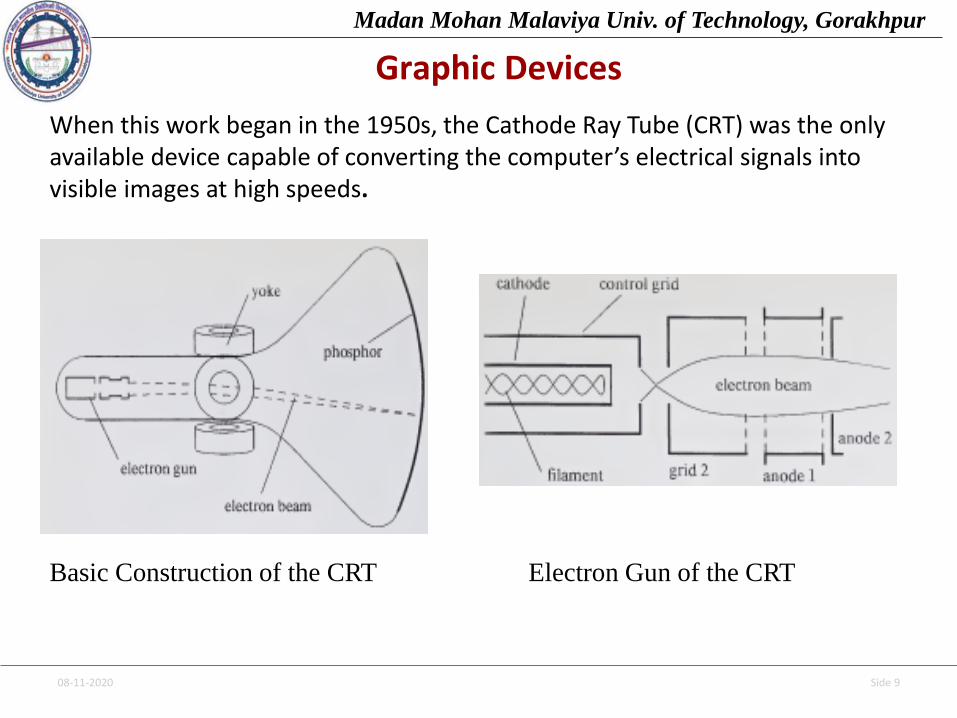
When this work began in the 1950s, the Cathode Ray Tube (CRT) was the only available device capable of converting the computer’s electrical signals into visible images at high speeds.
Basic Construction of the CRT Electron Gun of the CRT
08-11-2020 Side 10
Madan Mohan Malaviya Univ. of Technology, Gorakhpur
Graphic Devices (contd…)
The purpose of the electron gun in the CRT is to produce an electron beam withthe following properties:
1. It must be accurately focused so that it produces a sharp spot of light where itstrikes the phosphor;
2. It must have high velocity, since the brightness of the image depends on thevelocity of the electron beam;
3. Means must be provided to control the flow of electrons so that the intensity of the trace of the beam can be controlled.
Electrons are generated by a cathode heated by an electric filament.Surrounding the cathode is a cylindrical metal control grid, with a hole at oneend that allows electrons to escape. The control grid is kept at a lower potentialthan the cathode, creating an electrostatic field that directs the electronsthrough a point source; this simplifies the subsequent focusing process. Byaltering the control-grid potential, we can modify the rate of flow of electrons,or beam current, and can thus control the brightness of the image; we can evencut off the flow of electrons altogether.

08-11-2020 Side 11
Madan Mohan Malaviya Univ. of Technology, Gorakhpur
Graphic Devices (contd…)
Focusing is achieved by a focusing structure containing two or more cylindrical
metal plates at different potentials. These set up a toroidal electrostatic field
that effectively catches straying electrons and deflects them back toward the axis
of the beam. The result is a beam that is extremely finely focused and highly
concentrated at the precise moment at which it strikes the phosphor. An
accelerating structure is generally combined with the focusing structure. It
consists of two metal plates mounted perpendicular to the beam axis with holes
at their centers through which the beam can pass. The two plates are maintained
at a sufficiently high relative potential to accelerate the beam to the necessary
velocity; accelerating potentials of several thousand volts are not uncommon.
08-11-2020 Side 12
Madan Mohan Malaviya Univ. of Technology, Gorakhpur
Graphic Devices (contd…)
The resulting electron-gun structure has the advantage that it can be built
as a single physical unit and mounted inside the CRT envelope. Other types
of gun exist, whose focusing is performed by a coil mounted outside the
tube; this is called electromagnetic focusing to distinguish it from the more
common electrostatic method described in the preceding paragraph. The
electro magnetic technique can result in finer focusing, but the electrostatic
method is generally preferred in graphic displays because it leads to a
cheaper gun construction.
08-11-2020 Side 13
Madan Mohan Malaviya Univ. of Technology, Gorakhpur
Graphic Devices (contd…)
The Deflection System
A set of coils, or yoke, mounted at the neck of the tube, forms part of thedeflection system responsible for addressing in the CRT. Two pairs of coilsare used, one to control horizontal deflection, the other vertical. A primaryrequirement of the deflection system is that it deflect rapidly, since speedof deflection determines how much information can be displayed withoutflicker. To achieve fast deflection, we must use large-amplitude currents inthe yoke. An important part of the deflection system is therefore the set ofamplifiers that convert the small voltages received from the displaycontroller into currents of the appropriate magnitude.
The voltages used for deflection are generated by the display controllerfrom digital values provided by the computer. These values normallyrepresent coordinates that are converted into voltages by digital-to-analog(D/A) conversion. To draw a vector a pair of gradually changing voltagesmust be generated for the horizontal and vertical deflection coils.
08-11-2020 Side 14
Madan Mohan Malaviya Univ. of Technology, Gorakhpur
Graphic Devices (contd…)
Phosphors
The phosphors used in a graphic display are normally chosen for their colorcharacteristics and persistence. Ideally the persistence, measured as the timefor the brightness to drop to one-tenth of its initial value, should last about100 milliseconds or less, allowing refresh at 30-hertz rates without noticeablesmearing as the image moves. Color should preferably be white, particularlyfor applications where dark information appears on a light background. Thephosphor should also possess a number of other attributes: small grain sizefor added resolution, high efficiency in terms of electric energy converted tolight, and resistance to burning under prolonged excitation.
In attempts to improve performance in one or another of these respects,many different phosphors have been produced, using various compounds ofcalcium, cadmium, and zinc, together with traces of rare-earth elements.
08-11-2020 Side 15
Madan Mohan Malaviya Univ. of Technology, Gorakhpur
Graphic Devices (contd…)
The Beam-Penetration CRT
The normal CRT can generate images of only a single color, due to thelimitations of its phosphor. A color CRT device for line-drawing displays hasbeen developed, however; it uses a multilayer phosphor and achieves colorcontrol by modulating a normally constant parameter, namely the beam-accelerating potential.
The arrangement of the beam-penetration CRT is similar to that of normalCRTs; the only unusual component is the multilayer phosphor, in which alayer of red phosphor is deposited behind the initial layer of greenphosphor. If a fairly low-potential electron beam strikes the tube face, itexcites only the red phosphor and therefore produces a red trace. When theaccelerating potential is increased, the velocity of the beam striking thephosphor is greater, and as a result the beam penetrates into the greenphosphor, increasing the green component of the light output. A limitedrange of colors, including red, orange, yellow and green, can be generatedin this way.
08-11-2020 Side 16
Madan Mohan Malaviya Univ. of Technology, Gorakhpur
Graphic Devices (contd…)
The principal problem with the beam-penetration CRT is the need to change
the beam-accelerating potential by significant amounts in order to switch
colors. When the accelerating potential changes, the deflection system must
react to compensate. The hardware or software must be designed to
introduce adequate delays between changes in color, so that there is time for
voltages to settle. In order to prevent frequent delays and consequent flicker,
it is necessary to display all the red elements of the picture consecutively,
then change the accelerating potential and display the yellow elements, and
so on through all the different colors.
08-11-2020 Side 17
Madan Mohan Malaviya Univ. of Technology, Gorakhpur
Graphic Devices (contd…)
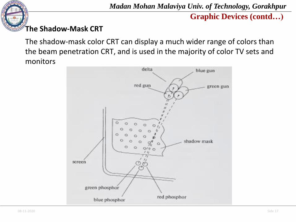
The Shadow-Mask CRT
The shadow-mask color CRT can display a much wider range of colors than the beam penetration CRT, and is used in the majority of color TV sets and monitors
08-11-2020 Side 18
Madan Mohan Malaviya Univ. of Technology, Gorakhpur
Graphic Devices (contd…)
Just behind the phosphor- coated face of the CRT is a metal plate, the shadowmask, pierced with small round holes in a triangular pattern. In place of theusual single electron gun, the shadow-mask tube uses three guns, grouped ina triangle or delta. These three guns are responsible for the red, green, andblue components of the light output of the CRT. The deflection system of theCRT operates on all three electron beams simultaneously, bringing all three tothe same point of focus on the shadow mask. Where the three beamsencounter holes in the mask, they pass through and strike the phosphor. Sincethey originate at three different points, however, they strike the phosphor inthree slightly different spots. The phosphor of the shadow-mask tube istherefore laid down very carefully in groups of three spots—one red, onegreen, and one blue—under each hole in the mask, in such a way that eachspot is struck only by electrons from the appropriate gun. The effect of themask is thus to “shadow” the spots of red phosphor from all but the redbeam, and likewise for the green and blue phosphor spots. We can thereforecontrol the light output in each of the three component colors by modulatingthe beam current of the corresponding gun.
08-11-2020 Side 19
Madan Mohan Malaviya Univ. of Technology, Gorakhpur
Graphic Devices (contd…)
remained relatively expensive compared with the monochrome CRT, andstill has a relatively poor performance in all respects except color range. Theshadow-mask CRT compares particularly unfavorably in resolution and inefficiency of light output. Both these effects are caused by the use of theshadow mask: the grain of the triangular pattern of holes sets a limit onattainable resolution, and the mask tends to block a large proportion of theavailable beam energy, reducing the total brightness. With the use of veryhigh accelerating potentials it is, however, possible to match the brightnessof monochrome CRT images.
A further, unique problem with the shadow-mask tube is that ofconvergence. It is extremely difficult to adjust the three guns and thedeflection system so that the electron beams are deflected exactlytogether, all three converging on the same hole in the shadow mask. Wherethey fail to converge the three component colors appear to spread in amanner reminiscent of a poorly-aligned color printing process. Often it ispossible to achieve adequate convergence over only a limited area of thescreen.
08-11-2020 Side 20
Madan Mohan Malaviya Univ. of Technology, Gorakhpur
Graphic Devices (contd…)
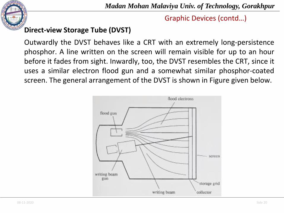
Direct-view Storage Tube (DVST)
Outwardly the DVST behaves like a CRT with an extremely long-persistencephosphor. A line written on the screen will remain visible for up to an hourbefore it fades from sight. Inwardly, too, the DVST resembles the CRT, since ituses a similar electron flood gun and a somewhat similar phosphor-coatedscreen. The general arrangement of the DVST is shown in Figure given below.

08-11-2020 Side 21
Madan Mohan Malaviya Univ. of Technology, Gorakhpur
Graphic Devices (contd…)
The beam is designed not to write directly on the phosphor, however, but on afine-mesh wire grid, coated with dielectric and mounted just behind the screen.A pattern of positive charge is deposited on the grid, and this pattern istransferred to the phosphor by a continuous flood of electrons issuing from aseparate flood gun. Just behind the storage mesh is a second grid, the collector,whose main purpose is to smooth out the flow of flood electrons. Theseelectrons pass through the collector at a low velocity, and are attracted to thepositively charged portions of the storage mesh but repelled by the rest.Electrons not repelled by the storage mesh pass right through it and strike thephosphor. In order to increase the energy of these relatively slow-movingelectrons and thus create a bright picture, the screen is maintained at a highpositive potential by means of a voltage applied to a thin aluminum coatingbetween the tube face and the phosphor.
Until they pass through the mesh, the flood electrons are still moving fairlyslowly and therefore hardly affect the charge on the mesh. One of theproblems with the DVST is in fact the difficulty in removing the stored charge toerase the picture.
08-11-2020 Side 22
Madan Mohan Malaviya Univ. of Technology, Gorakhpur
Graphic Devices (contd…)
The normal erasing method is to apply a positive voltage to the storagemesh for one second or more; this removes all the charge but alsogenerates a rather unpleasant flash over the entire screen surface. Thiserase problem is perhaps the most severe drawback of the DVST, for itprevents the use of the device for dynamic graphics applications. Otherproblems are its relatively poor contrast, a result of the comparatively lowaccelerating potential applied to the flood electrons, and the gradualdegradation of the picture quality as background glow accumulates; thisglow is caused by the small amounts of charge deposited on the mesh byrepelled flood electrons.
In terms of performance, the DVST is somewhat inferior to the refresh CRT.Only a single level of line intensity can be displayed, and only green-phosphor tubes are available. Until recently, the DVST used relatively small-screen tubes; now tubes with 19-inch and 25-inch diagonals are available.The smaller DVSTs have the advantage of a flat screen, not present in thelarger variety. Some storage-tube displays possess the capability to refresha limited number of vectors.

08-11-2020 Side 23
Madan Mohan Malaviya Univ. of Technology, Gorakhpur
Graphic Devices (contd…)
TABLETS
The term tablet is used to describe a flat surface, generally separate from the display, on which the user draws with a stylus (see Figure given below).
The similarity of the tablet and stylus to paper and pencil makes them a particularly natural combination for graphical input.
08-11-2020 Side 24
Madan Mohan Malaviya Univ. of Technology, Gorakhpur
Graphic Devices (contd…)
Early Tablet Devices
The RAND Tablet was developed at the RAND Corporation. It provides a flatdrawing area 10 inches square and rests on a table top. Embedded in thesurface of the tablet are 1024 lines parallel to the x axis and 1024 linesparallel to the y axis. Each individual line carries a unique digitally codedsignal that can be picked up by the stylus. Inside the stylus a sensitiveamplifier detects the pulses from the lines, amplifies them, and deliversthem via coaxial cable to decoding logic, which in turn deposits binaryinteger coordinates in the tablet’s buffer registers. The stylus has a smallswitch in the tip, whose status is kept in an extra bit in the buffer register.
An alternative coordinate-input technique uses voltage gradients within aresistive plate. In the simplest configuration, a sheet of partially conductivematerial is used as the tablet surface. During successive time intervals, apotential is applied first horizontally and then vertically across the sheet. Thestylus is kept in contact with the conductive sheet and senses a potentialcorresponding to its position.

08-11-2020 Side 25
Madan Mohan Malaviya Univ. of Technology, Gorakhpur
Graphic Devices (contd…)
The x and y coordinates of the pen can be determined by measuring the potential during the horizontal and vertical time periods. Absence of any potential indicates that the pen is not in contact with the surface.
An alternative coordinate-input technique uses voltage gradients within aresistive plate. In the simplest configuration, a sheet of partially conductivematerial is used as the tablet surface. During successive time intervals, apotential is applied first horizontally and then vertically across the sheet. Thestylus is kept in contact with the conductive sheet and senses a potentialcorresponding to its position. The * and y coordinates of the pen can bedetermined by measuring the potential during the horizontal and verticaltime periods. Absence of any potential Indicates that the pen is not in contactwith the surface.

08-11-2020 Side 26
Madan Mohan Malaviya Univ. of Technology, Gorakhpur
Graphic Devices (contd…)
The Acoustic Tablet
It depends on the use of strip microphones, which are mounted along two adjacent edges of the tablet, as shown in Figure given below.
The stylus has a small piece of ceramic mounted close to its tip, and atregular intervals a small spark is generated across the surface of the ceramicbetween two electrodes. The microphones pick up the pulse of soundgenerated by the spark, and two counters record the delay between creatingthe spark and receiving the sound. These two delays are proportional to thestylus distance from the two edges of the tablet where the microphones aremounted. They can therefore be used as x and y values.
08-11-2020 Side 27
Madan Mohan Malaviya Univ. of Technology, GorakhpurGraphic Devices (contd…)
The Electro-acoustic Tablet
Another acoustic technique has been employed in the electro-acoustic tablet:in this device, the writing surface is a sheet of magnetostrictive materialacting like a row of delay lines. An electric pulse travels through the sheet,first horizontally and then vertically, and is detected by a sensor in the stylusas it passes by. A counter is used to determine the delay from the time thepulse is issued to the time it is detected; from this value the position of thestylus can be determined. Pulses may be issued at any frequency up to about200 pairs per second, adequate to track the stylus at 5-millisecond intervals.
The electro-acoustic tablet is quieter in operation than its acousticcounterpart and is less affected by ambient noise or air movement. Both typesof tablet can be constructed to sizes in excess of 1 meter square.
08-11-2020 Side 28
Madan Mohan Malaviya Univ. of Technology, Gorakhpur
Graphic Devices (contd…)
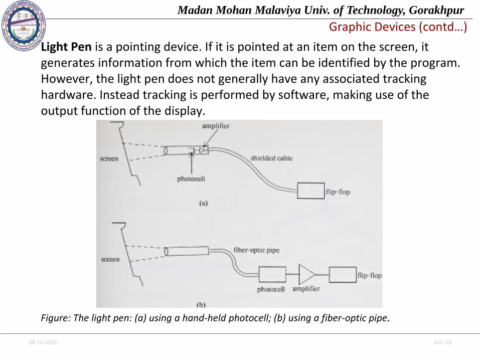
Light Pen is a pointing device. If it is pointed at an item on the screen, it generates information from which the item can be identified by the program. However, the light pen does not generally have any associated tracking hardware. Instead tracking is performed by software, making use of the output function of the display.
Figure: The light pen: (a) using a hand-held photocell; (b) using a fiber-optic pipe.
08-11-2020 Side 29
Madan Mohan Malaviya Univ. of Technology, Gorakhpur
Graphic Devices (contd…)
Two alternative arrangements are shown in Figure. In each case the two mainelements of the light pen are a photocell and an optical system which focusesonto it any light in the pen’s field of view. A pen-shaped housing permits thelight pen to be held in the hand and pointed at the display screen. On thishousing is either a finger- operated switch or a shutter that must bedepressed to allow light to reach the photocell. The output of the photocell isamplified and fed to a flip-flop which is set whenever the pen is pointed at asufficiently bright source of light. This flip-flop can be read and cleared by thecomputer.
Pointing operations are easily programmed for the light pen, particularly ifwe are using a point-plotting display: we can test the light-pen flip-flop afterdisplaying each point and thus determine the exact spot at which the pen ispointing. Alternatively we can use an interrupt feature to indicate when theflip-flop is set. The computer can read the contents of the display’s addressregister when an interrupt occurs and from them determine which item wasseen by the pen.
08-11-2020 Side 30
Madan Mohan Malaviya Univ. of Technology, Gorakhpur
Graphic Devices (contd…)
All light-pen programs depend on a rapid response from the pen when it ispointed at the screen. A particularly fast response is required if the light penis to be used with high-speed displays. Suppose, for example, a displayexecutes one instruction every 2 microseconds but the delay betweendisplaying a point or line and setting the light pen flip-flop is 3 microseconds.By the time this happens, the display will be processing either the nextinstruction or the one after that. The program may therefore incorrectlyidentify the seen item.
Fast-response light pens can be built by using a highly sensitive photocellsuch as a photomultiplier tube. However, this sort of device is too bulky to beheld in the hand, so the light must be focused onto it by a fiber-optic pipe, asshown in Figure b. Transistor-type photocells, such as the photodiode, arecheap and small enough to be hand-held. However, photodiodes generallytake one or more microseconds to respond and are therefore more suited tolight pens for slower displays.
08-11-2020 Side 31
Madan Mohan Malaviya Univ. of Technology, Gorakhpur
Graphic Devices (contd…)
The light pen communicates with the computer through a single 1-bit statusregister that is set whenever the light pen sees an intensified spot on thescreen. The identity of the spot is determined by reading the display addressregister as soon as the status bit is set. Instead of relying on the computer torespond immediately, the display processor halts when the status bit is set,thus ensuring that the address register will still be valid when the computerreads it. Nevertheless it is important for the computer to respond quickly to achange in the status bit; if the display remains off for more than a millisecondor two, the user will notice a flickering effect. The status bit generates aninterrupt when it is set, and this invokes a high-priority task that reads thedisplay address register and restarts the display.
Two kinds of light-pen interrupts may occur. The user may point the pen atan item on the screen in order to select it; this results in a selection interrupt.When the user is positioning with the pen, a tracking pattern is displayed inorder to follow the pen’s movement and tracking interrupts are generatedwhen the pen sees the pattern. The light-pen task must distinguish betweenselection and tracking interrupts.
08-11-2020 Side 32
Madan Mohan Malaviya Univ. of Technology, Gorakhpur
Graphic Devices (contd…)
This can be achieved by checking the display address register to see whetherthe display has been stopped while displaying the tracking pattern. If it has,the polling task proceeds with the tracking process; if it has not, the interruptis treated as a selection interrupt and a selection event is generated.
Light-Pen Tracking
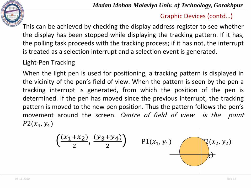
When the light pen is used for positioning, a tracking pattern is displayed inthe vicinity of the pen’s field of view. When the pattern is seen by the pen atracking interrupt is generated, from which the position of the pen isdetermined. If the pen has moved since the previous interrupt, the trackingpattern is moved to the new pen position. Thus the pattern follows the pen’smovement around the screen. Centre of field of view is the point𝑃2(𝑥4, 𝑦4)
(𝑥1+𝑥2)
2, (𝑦3+𝑦4)
2P1(𝑥1, 𝑦1) 𝑃2(𝑥2, 𝑦2)
𝑃3(𝑥3, 𝑦3)
08-11-2020 Side 33
Madan Mohan Malaviya Univ. of Technology, Gorakhpur
Graphic Devices (contd…)
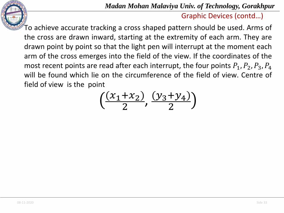
To achieve accurate tracking a cross shaped pattern should be used. Arms ofthe cross are drawn inward, starting at the extremity of each arm. They aredrawn point by point so that the light pen will interrupt at the moment eacharm of the cross emerges into the field of the view. If the coordinates of themost recent points are read after each interrupt, the four points 𝑃1, 𝑃2, 𝑃3, 𝑃4will be found which lie on the circumference of the field of view. Centre offield of view is the point
(𝑥1+𝑥2)2
, (𝑦3+𝑦4)2
08-11-2020 Side 34
Madan Mohan Malaviya Univ. of Technology, Gorakhpur
Simple Line Drawing MethodsPoint-plotting Techniques
The very first graphical displays were of the point-plotting variety. They did not useframe buffers but were fed with a stream of point coordinates by the computer. Only avery limited number of points could be displayed in this fashion without flicker.
Point-plotting displays of this kind were made obsolete by the introduction of line-drawing displays in the mid-1960s. The line-drawing display can draw completesegments of straight lines without plotting each individual pixel on the line; it thereforehas a much higher capacity than the point-plotting display for line drawings. It also doesaway with the need to compute the position of each pixel in the picture.
Despite the obsolescence of the original point-plotting displays, the techniquesdeveloped for programming them remain relevant today. The main reason isthat point-plotting techniques have become essential in programming frame-buffer displays, where once again the intensity of each dot must be separatelycomputed. Point-plotting techniques also serve to introduce us to theincremental methods so frequently useful in computer graphics.
08-11-2020 Side 35
Madan Mohan Malaviya Univ. of Technology, Gorakhpur
Simple Line Drawing Methods (contd…)
COORDINATE SYSTEMS
Point-plotting techniques are based on the use of a cartesian coordinatesystem. Points are addressed by their x and y coordinates; the value of xincreases from left to right and y likewise from bottom to top.
Points are plotted in response to digital signals from the computer. This meansthat they cannot be positioned with infinite precision; instead we are limitedby the precision of the digital values presented to the display.
In most cases precision is based on the resolution of the display screen.Nothing is gained by increasing coordinate precision much beyond theresolution of the screen because the observer will not be able to tell thedifference. If precision is much less than resolution, however, there will beresolvable points on the screen at which it is impossible to display a dot; thiswill cause visible gaps in lines. Hence when a display is designed, its coordinateprecision is made approximately equal to screen resolution.
08-11-2020 Side 36
Madan Mohan Malaviya Univ. of Technology, Gorakhpur
Simple Line Drawing Methods (contd…)
Qualities of good line drawing algorithms:
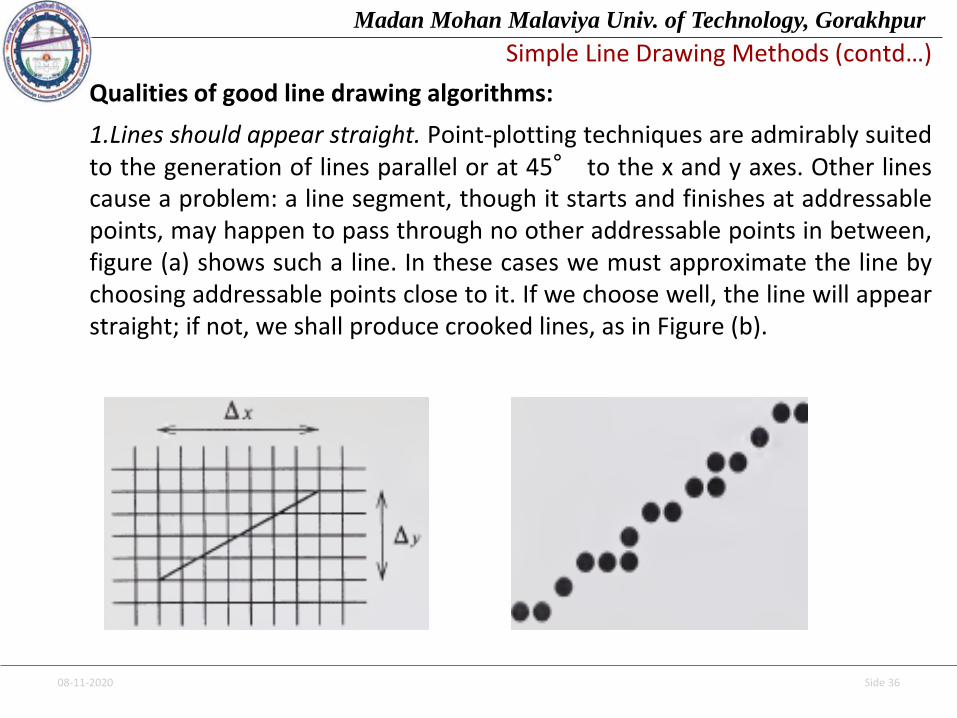
1.Lines should appear straight. Point-plotting techniques are admirably suitedto the generation of lines parallel or at 45° to the x and y axes. Other linescause a problem: a line segment, though it starts and finishes at addressablepoints, may happen to pass through no other addressable points in between,figure (a) shows such a line. In these cases we must approximate the line bychoosing addressable points close to it. If we choose well, the line will appearstraight; if not, we shall produce crooked lines, as in Figure (b).
(a) (b)
08-11-2020 Side 37
Madan Mohan Malaviya Univ. of Technology, Gorakhpur
Simple Line Drawing Methods (contd…)
2. Lines should terminate accurately. Unless lines are plotted accurately, they mayterminate at the wrong place. The effect is often seen as a small gap between theendpoint of one line and the starting point of the next or as a cumulative error.
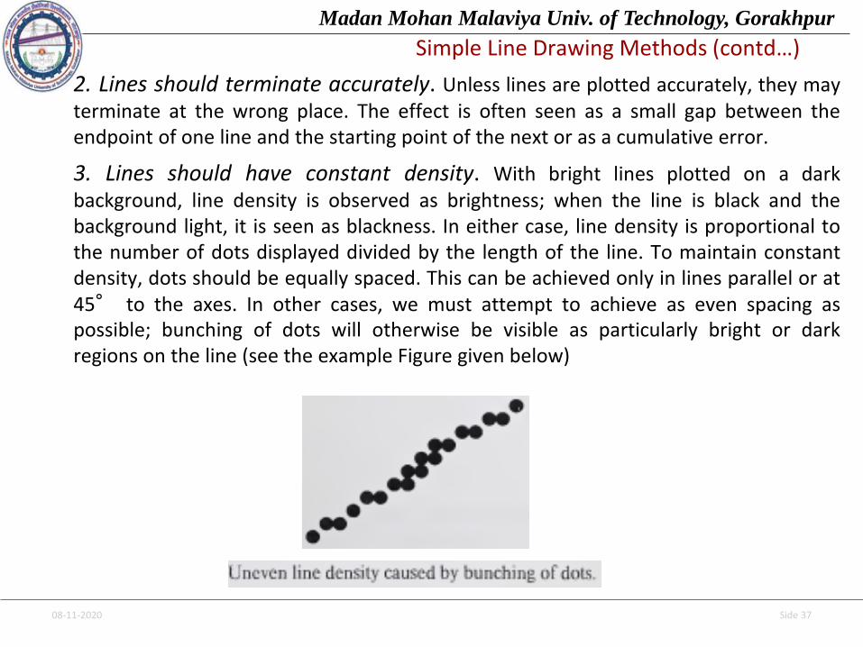
3. Lines should have constant density. With bright lines plotted on a darkbackground, line density is observed as brightness; when the line is black and thebackground light, it is seen as blackness. In either case, line density is proportional tothe number of dots displayed divided by the length of the line. To maintain constantdensity, dots should be equally spaced. This can be achieved only in lines parallel or at45° to the axes. In other cases, we must attempt to achieve as even spacing aspossible; bunching of dots will otherwise be visible as particularly bright or darkregions on the line (see the example Figure given below)
08-11-2020 Side 38
Madan Mohan Malaviya Univ. of Technology, Gorakhpur
Simple Line Drawing Methods (contd…)
Line density should be independent of line length and angle. This is a difficultrequirement to satisfy. As we have just seen, to achieve constant line densitywe must maintain a constant number of dots per unit length. Before plottingthe line we must therefore determine its exact length, which involvescomputing a square root. Also we must be able to control the rate, in terms ofdistance traveled, at which dots are plotted. Neither of these is easily done.Normally the best we can do is to compute an approximate line-lengthestimate and to use a line-generation algorithm that keeps line densityconstant to within the accuracy of this estimate.
Lines should be drawn rapidly. In interactive applications we would like lines toappear rapidly on the screen. This implies using the minimum of computationto draw the line; ideally, this computation should be performed by special-purpose hardware.
08-11-2020 Side 39
Madan Mohan Malaviya Univ. of Technology, Gorakhpur
Simple Line Drawing Methods (contd…)
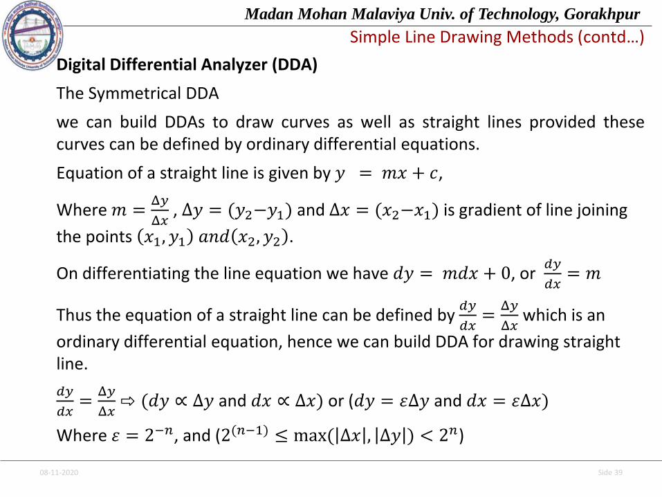
Digital Differential Analyzer (DDA)
The Symmetrical DDA
we can build DDAs to draw curves as well as straight lines provided thesecurves can be defined by ordinary differential equations.
Equation of a straight line is given by 𝑦 = 𝑚𝑥 + 𝑐,
Where 𝑚 =Δ𝑦
Δ𝑥, ∆𝑦 = (𝑦2−𝑦1) and ∆𝑥 = (𝑥2−𝑥1) is gradient of line joining
the points 𝑥1, 𝑦1 𝑎𝑛𝑑 𝑥2, 𝑦2 .
On differentiating the line equation we have 𝑑𝑦 = 𝑚𝑑𝑥 + 0, or 𝑑𝑦
𝑑𝑥= 𝑚
Thus the equation of a straight line can be defined by 𝑑𝑦
𝑑𝑥=
Δ𝑦
Δ𝑥which is an
ordinary differential equation, hence we can build DDA for drawing straight line.
𝑑𝑦
𝑑𝑥=
Δ𝑦
Δ𝑥⇨ (𝑑𝑦 ∝ ∆𝑦 and 𝑑𝑥 ∝ ∆𝑥) or (𝑑𝑦 = 𝜀∆𝑦 and 𝑑𝑥 = 𝜀∆𝑥)
Where 𝜀 = 2−𝑛, and (2(𝑛−1) ≤ max( ∆𝑥 , ∆𝑦 ) < 2𝑛)

08-11-2020 Side 40
Madan Mohan Malaviya Univ. of Technology, Gorakhpur
Simple Line Drawing Methods (contd…)
• The incrementing values are repeatedly added to the fractional parts, and whenever the result overflows, the corresponding integer part is incremented. The integer parts of the x and y registers are used in plotting the line. This would normally have the effect of truncating rather than rounding, so we initialize the DDA with the value 0.5 in each of the fractional parts to achieve true rounding.
• One advantage of this arrangement is that it allows us to detect changes in x and y and hence to avoid plotting the same point twice.
• This iteration continues till 𝑥2 is reached If ( ∆𝑥 > ∆𝑦 ) else till 𝑦2 .
08-11-2020 Side 41
Madan Mohan Malaviya Univ. of Technology, Gorakhpur
Simple Line Drawing Methods (contd…)
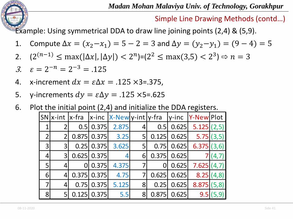
Example: Using symmetrical DDA to draw line joining points (2,4) & (5,9).
1. Compute ∆𝑥 = (𝑥2−𝑥1) = 5 − 2 = 3 and ∆𝑦 = (𝑦2−𝑦1) = (9 − 4) = 5
2. (2(𝑛−1) ≤ max( ∆𝑥 , ∆𝑦 ) < 2𝑛)=(22 ≤ max(3,5) < 23) ⇨ 𝑛 = 3
3. 𝜀 = 2−𝑛 = 2−3 = .125
4. x-increment 𝑑𝑥 = 𝜀∆𝑥 = .125 ×3=.375,
5. y-increments 𝑑𝑦 = 𝜀∆𝑦 = .125 ×5=.625
6. Plot the initial point (2,4) and initialize the DDA registers.SN x-int x-fra x-inc X-New y-int y-fra y-inc Y-New Plot
1 2 0.5 0.375 2.875 4 0.5 0.625 5.125 (2,5)
2 2 0.875 0.375 3.25 5 0.125 0.625 5.75 (3,5)
3 3 0.25 0.375 3.625 5 0.75 0.625 6.375 (3,6)
4 3 0.625 0.375 4 6 0.375 0.625 7 (4,7)
5 4 0 0.375 4.375 7 0 0.625 7.625 (4,7)
6 4 0.375 0.375 4.75 7 0.625 0.625 8.25 (4,8)
7 4 0.75 0.375 5.125 8 0.25 0.625 8.875 (5,8)
8 5 0.125 0.375 5.5 8 0.875 0.625 9.5 (5,9)
08-11-2020 Side 42
Madan Mohan Malaviya Univ. of Technology, Gorakhpur
Simple Line Drawing Methods (contd…)
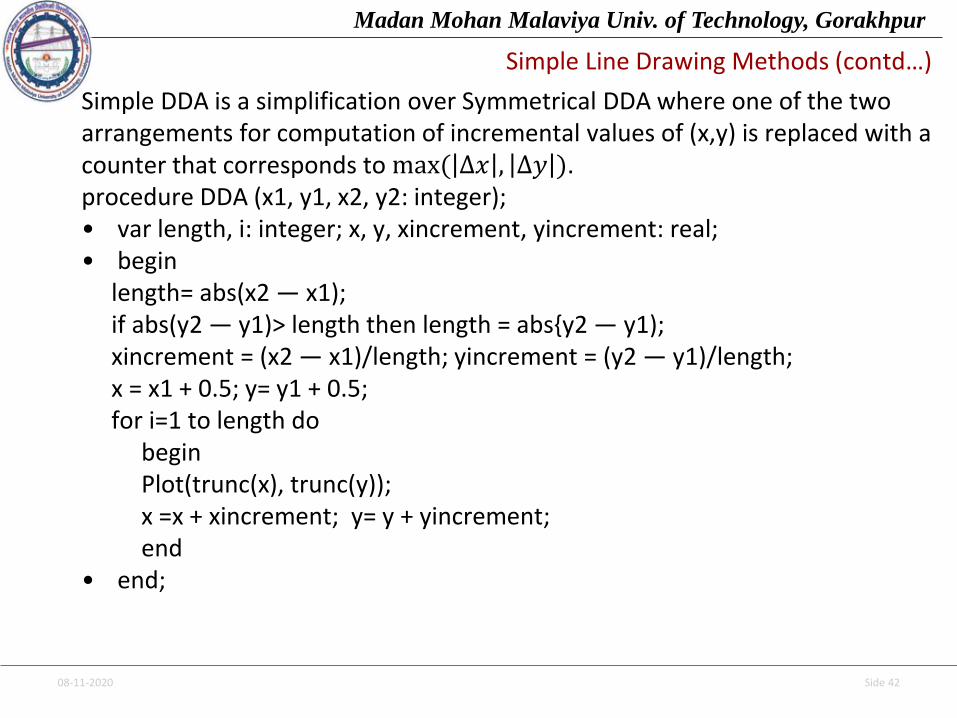
Simple DDA is a simplification over Symmetrical DDA where one of the two arrangements for computation of incremental values of (x,y) is replaced with a counter that corresponds to max( ∆𝑥 , ∆𝑦 ).procedure DDA (x1, y1, x2, y2: integer); • var length, i: integer; x, y, xincrement, yincrement: real; • begin
length= abs(x2 — x1); if abs(y2 — y1)> length then length = abs{y2 — y1); xincrement = (x2 — x1)/length; yincrement = (y2 — y1)/length; x = x1 + 0.5; y= y1 + 0.5; for i=1 to length do
begin Plot(trunc(x), trunc(y)); x =x + xincrement; y= y + yincrement;end
• end;

08-11-2020 Side 43
Madan Mohan Malaviya Univ. of Technology, Gorakhpur
Simple Line Drawing Methods (contd…)
Example: Using Simple DDA to draw line joining points (2,4) & (5,9).
1. Compute ∆𝑥 = (𝑥2−𝑥1) = 5 − 2 = 3 and ∆𝑦 = (𝑦2−𝑦1) = (9 − 4) = 5
2. length=max(3,5)=5, xincrement=3/5=0.6; yincrement=5/5=1;
3. x=x1+0.5; y=y1+0.5,
4. For i=1 to length begin Plot (trunc(x), trunc(y));
x=x+xincrement; y=y+yincrement;
end;
5.Stop. SN x x-inc X-New y y-inc Y-New Plot
1 2 0.5 2.5 4 0.5 4.5 (2,4)
2 2.5 0.6 3.1 4.5 1 5.5 (3,5)
3 3.1 0.6 3.7 5.5 1 6.5 (3,6)
4 3.7 0.6 4.3 6.5 1 7.5 (4,7)
5 4.3 0.6 4.9 7.5 1 8.5 (4,8)
6 4.9 0.6 5.5 8.5 1 9.5 (5,9)

08-11-2020 Side 44
Madan Mohan Malaviya Univ. of Technology, Gorakhpur
Simple Line Drawing Methods (contd…)
Bresenham’s Algorithm
It is designed so that each iteration changes one of the coordinate values by ±1. The other coordinate may or may not change, depending on the value of an error term maintained by the algorithm. This error term records the distance, measured perpendicular to the axis of greatest movement, between the exact path of the line and the actual dots generated.
At each iteration of the algorithm the slope of the line,
A Δ𝑦
Δ𝑥, is added to the error term e. Before this is done,
the sign of e is used to determine whether to increment
the y coordinate of the current point. A positive e value indicates that the exact path of the line lies above the current point; therefore the y coordinate is incremented, and 1 is subtracted from e. If e is negative the y coordinate value is left unchanged.
08-11-2020 Side 45
Madan Mohan Malaviya Univ. of Technology, Gorakhpur
Simple Line Drawing Methods (contd…)
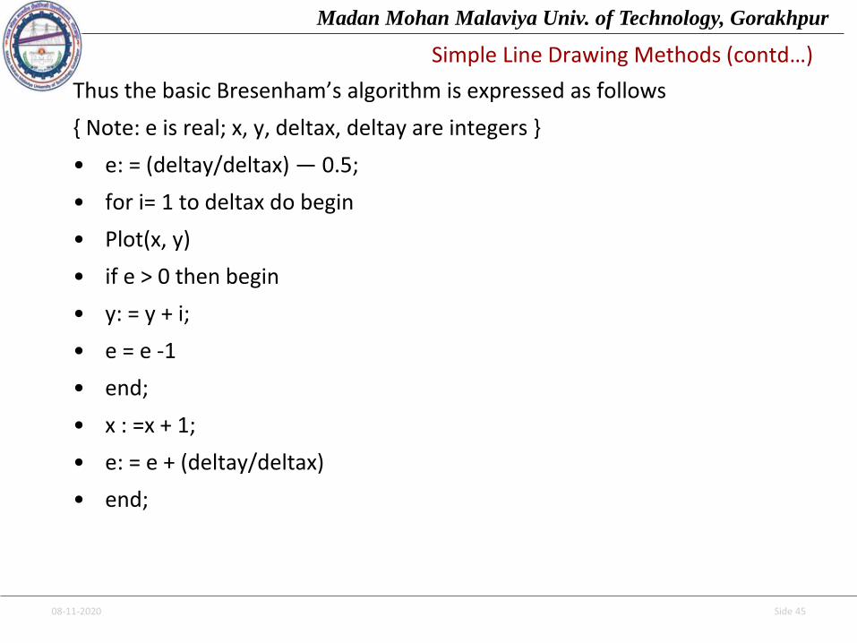
Thus the basic Bresenham’s algorithm is expressed as follows
{ Note: e is real; x, y, deltax, deltay are integers }
• e: = (deltay/deltax) — 0.5;
• for i= 1 to deltax do begin
• Plot(x, y)
• if e > 0 then begin
• y: = y + i;
• e = e -1
• end;
• x : =x + 1;
• e: = e + (deltay/deltax)
• end;

08-11-2020 Side 46
Madan Mohan Malaviya Univ. of Technology, Gorakhpur
Simple Line Drawing Methods (contd…)
The Circle-generating DDA
The principle of the DDA can be extended to other curves; one such curve is the circular arc. The differential equation of a circle with center at the origin can be written
𝑑𝑦
𝑑𝑥=
−x
y⇨ (𝑑𝑦 ∝ −𝑥 and 𝑑𝑥 ∝ 𝑦) or (𝑑𝑦 = −𝜀𝑥 and 𝑑𝑥 = 𝜀𝑦)
𝑥𝑛+1 = 𝑥𝑛 + 𝜀𝑦𝑛, 𝑦𝑛+1 = 𝑦𝑛 − 𝜀𝑥𝑛 …….(1)
where 𝜀 = 2−𝑛, and (2(𝑛−1) ≤ 𝑟 < 2𝑛)
r being the radius of the circle.
Unfortunately the method just described plots a spiral, not a circular arc. Each step is made in a direction perpendicular to a radius of the circle; each point is therefore slightly farther from the center than the one before. This problem is easily solved by following modifications:
𝑥𝑛+1 = 𝑥𝑛 + 𝜀𝑦𝑛, 𝑦𝑛+1 = 𝑦𝑛 − 𝜀𝑥𝑛+1 ........(2)
Solution is based on following reasoning
08-11-2020 Side 47
Madan Mohan Malaviya Univ. of Technology, Gorakhpur
Simple Line Drawing Methods (contd…)
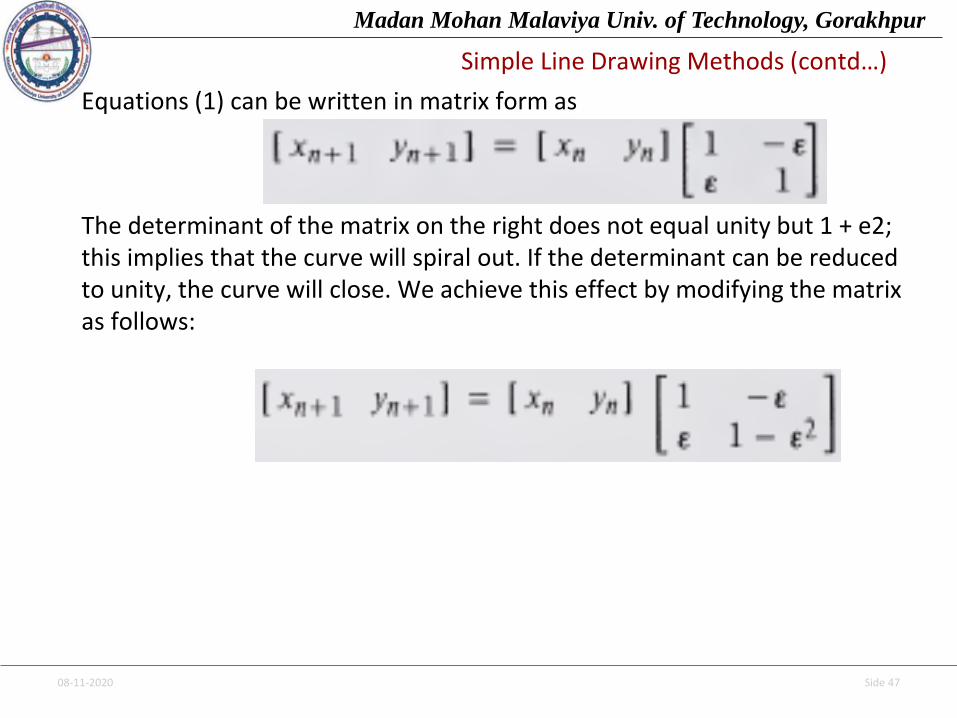
Equations (1) can be written in matrix form as
The determinant of the matrix on the right does not equal unity but 1 + e2; this implies that the curve will spiral out. If the determinant can be reduced to unity, the curve will close. We achieve this effect by modifying the matrix as follows:
Related Documents