Machine Tool Controller Design Joe, Chien-Yi Lee No. 191, 38 Road, Taichung Industrial Area. Taichung, Taiwan 40768, R.O.C. Tel: +886-4-2358-3993 ext.663 E-mail: [email protected] 課程講義 禁止轉載

Welcome message from author
This document is posted to help you gain knowledge. Please leave a comment to let me know what you think about it! Share it to your friends and learn new things together.
Transcript
Machine Tool Controller Design
Joe, Chien-Yi Lee
No. 191, 38 Road, Taichung Industrial Area.Taichung, Taiwan 40768, R.O.C.Tel: +886-4-2358-3993 ext.663E-mail: [email protected]
課程講義
禁止轉載
Joe LeeCopyright 2016 ITRI
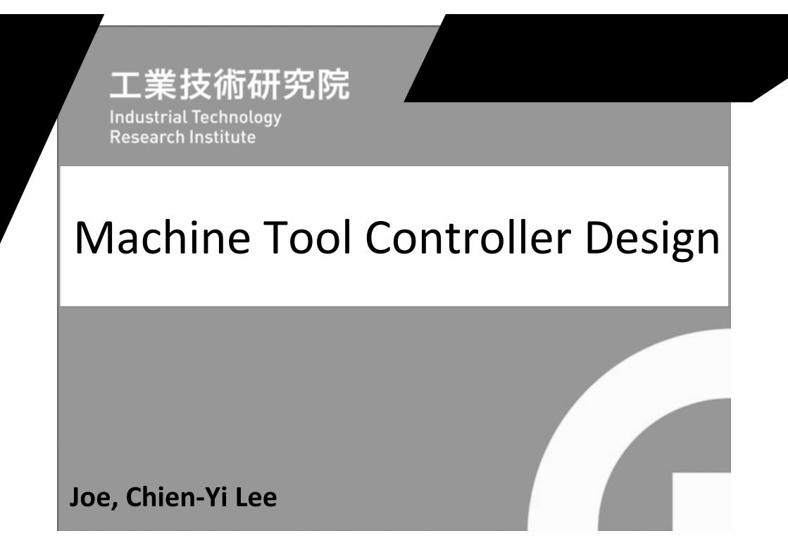
FAGOR 8070CNC Controller System
2Photo Taken From: Internet
課程講義
禁止轉載
Joe LeeCopyright 2016 ITRI 3
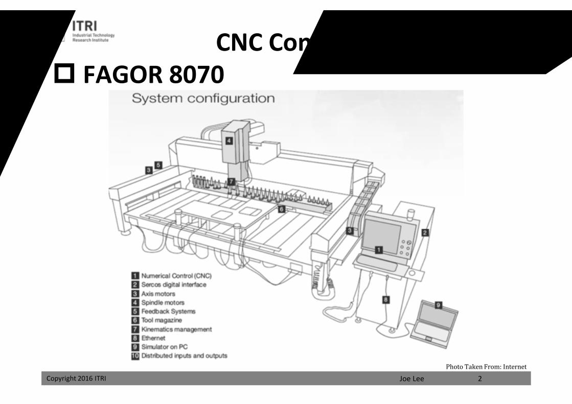
Controller System Architecture
Photo Taken From: Internet
課程講義
禁止轉載
Joe LeeCopyright 2016 ITRI Copyright 2016 ITRI
Controller Hardware Design一、Hardware Classification
1. Printed-circuit Board1. Large PCB2. Module
2. Microprocessor Number1. Single2. Multi
3. Hardware Manufacturing1. Dedicated2. Universal
4. Openness1. Closed2. PC Embedded NC3. NC Embedded PC4. Pure-soft Open CNC
4
課程講義
禁止轉載
Joe LeeCopyright 2016 ITRI Copyright 2016 ITRI
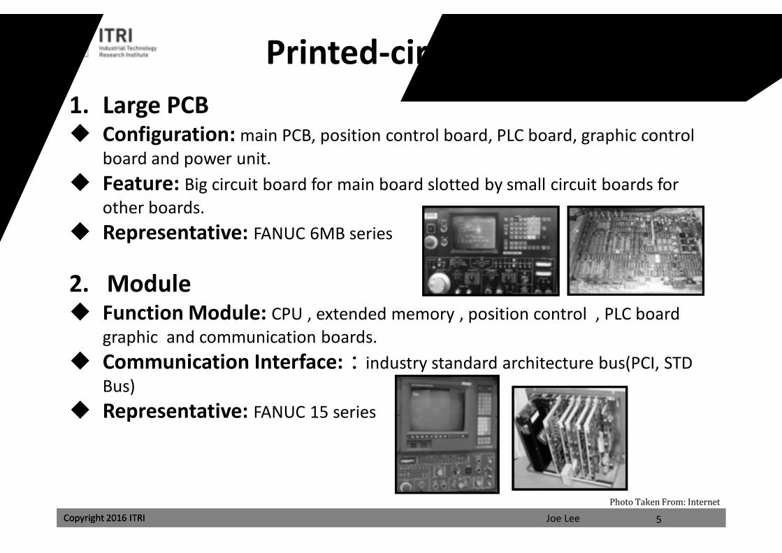
Printed-circuit Board Type1. Large PCB Configuration: main PCB, position control board, PLC board, graphic control
board and power unit. Feature: Big circuit board for main board slotted by small circuit boards for
other boards. Representative: FANUC 6MB series
2. Module Function Module: CPU , extended memory , position control , PLC board
graphic and communication boards. Communication Interface::industry standard architecture bus(PCI, STD
Bus) Representative: FANUC 15 series
5
Photo Taken From: Internet
課程講義
禁止轉載
Joe LeeCopyright 2016 ITRI Copyright 2016 ITRI
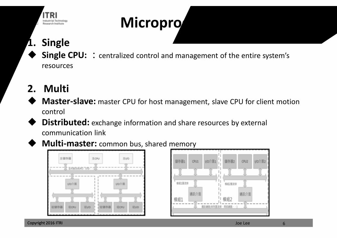
Microprocessor Number1. Single Single CPU: :centralized control and management of the entire system’s
resources
2. Multi Master-slave: master CPU for host management, slave CPU for client motion
control Distributed: exchange information and share resources by external
communication link Multi-master: common bus, shared memory
6
課程講義
禁止轉載
Joe LeeCopyright 2016 ITRI Copyright 2016 ITRI
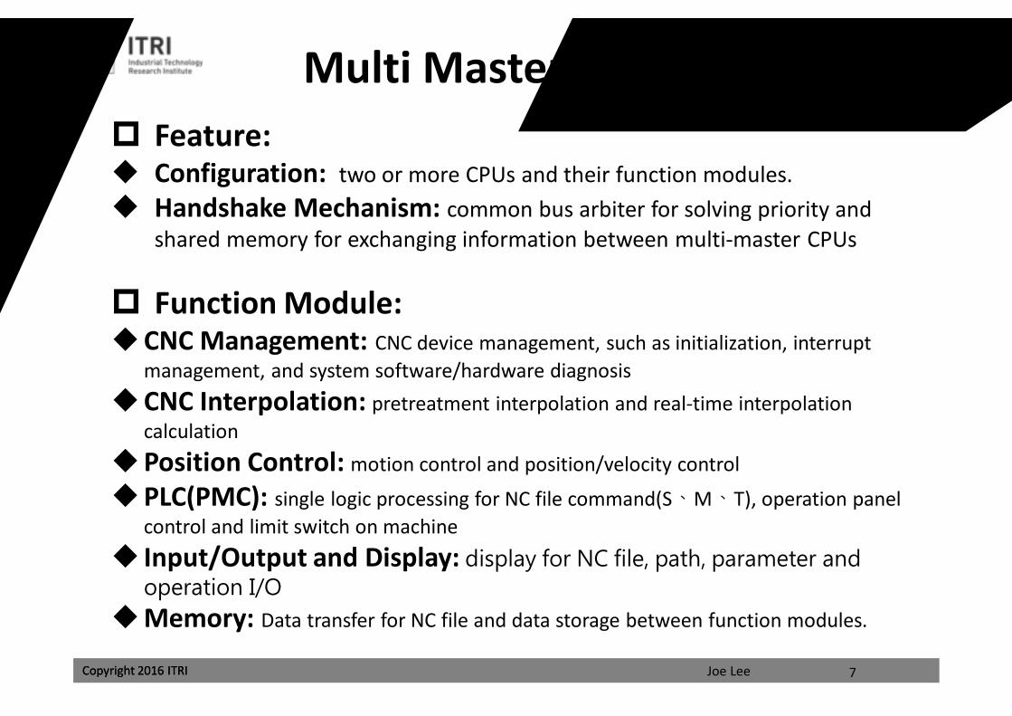
Multi Master Microprocessors Feature: Configuration: two or more CPUs and their function modules. Handshake Mechanism: common bus arbiter for solving priority and
shared memory for exchanging information between multi-master CPUs
Function Module:CNC Management: CNC device management, such as initialization, interrupt
management, and system software/hardware diagnosisCNC Interpolation: pretreatment interpolation and real-time interpolation
calculationPosition Control: motion control and position/velocity control
PLC(PMC): single logic processing for NC file command(S、M、T), operation panel control and limit switch on machine
Input/Output and Display: display for NC file, path, parameter and operation I/O
Memory: Data transfer for NC file and data storage between function modules.
7
課程講義
禁止轉載
Joe LeeCopyright 2016 ITRI Copyright 2016 ITRI
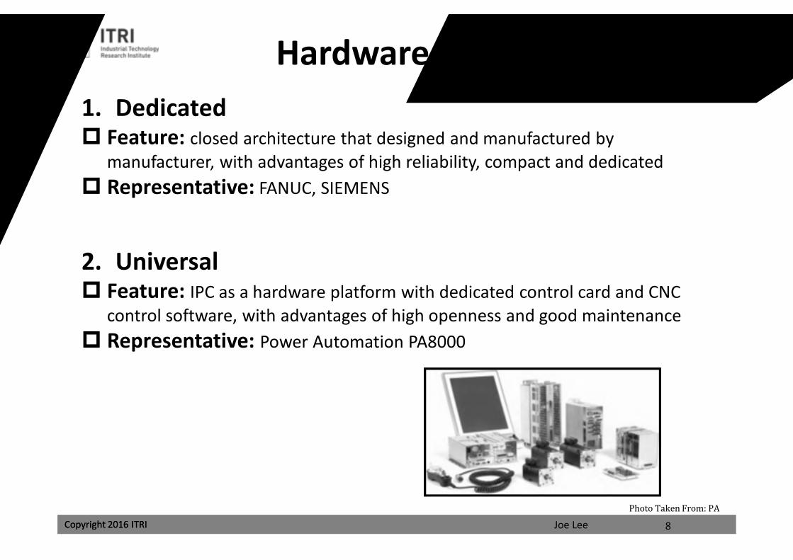
Hardware Manufacturing1. Dedicated Feature: closed architecture that designed and manufactured by
manufacturer, with advantages of high reliability, compact and dedicated Representative: FANUC, SIEMENS
2. Universal Feature: IPC as a hardware platform with dedicated control card and CNC
control software, with advantages of high openness and good maintenance Representative: Power Automation PA8000
8
Photo Taken From: PA
課程講義
禁止轉載
Joe LeeCopyright 2016 ITRI Copyright 2016 ITRI
Openness1. Closed Feature: user cannot add, change and maintain any function Representative: FANUC 0、MITSUBISHIM 50、SIEMENS 810。
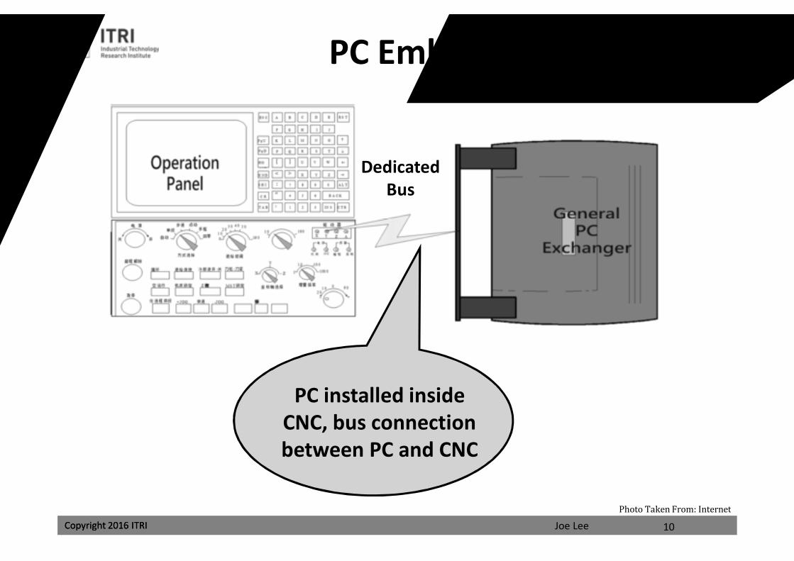
2. PC Embedded NC Feature: PC installed in CNC, with certain openness but system kernel modified
is allowed Representative: FANUC 18i/16i、SIEMENS 840D、NUM 1060
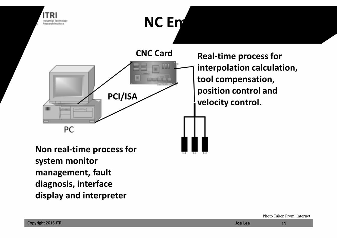
3. NC Embedded PC Feature: composition of motion control card and PC, motion control card is used
for CNC system and usually a high speed DSP is used as CPU Representative: American Delta Tau company PMAC CNC system based on
PMAC multi-axis motion control card, Japan MAZAK company MAZATROL 640 CNCsystem based on Mitsubishi Electric’s MELDAS MAGIC 64
4. Pure-soft Open CNC Feature: RTLinux software development platform as a pure software CNC system Representative: American MDSI company Open CNC, German PA company
PA80009
課程講義
禁止轉載
Joe LeeCopyright 2016 ITRI Copyright 2016 ITRI
PC Embedded CNC
10
PC installed inside CNC, bus connection between PC and CNC
Dedicated Bus
Photo Taken From: Internet
課程講義
禁止轉載
Joe LeeCopyright 2016 ITRI Copyright 2016 ITRI
NC Embedded PC
11
PCI/ISA
Non real-time process for system monitor management, fault diagnosis, interface display and interpreter
Real-time process for interpolation calculation, tool compensation, position control and velocity control.
CNC Card
Photo Taken From: Internet
課程講義
禁止轉載
Joe LeeCopyright 2016 ITRI
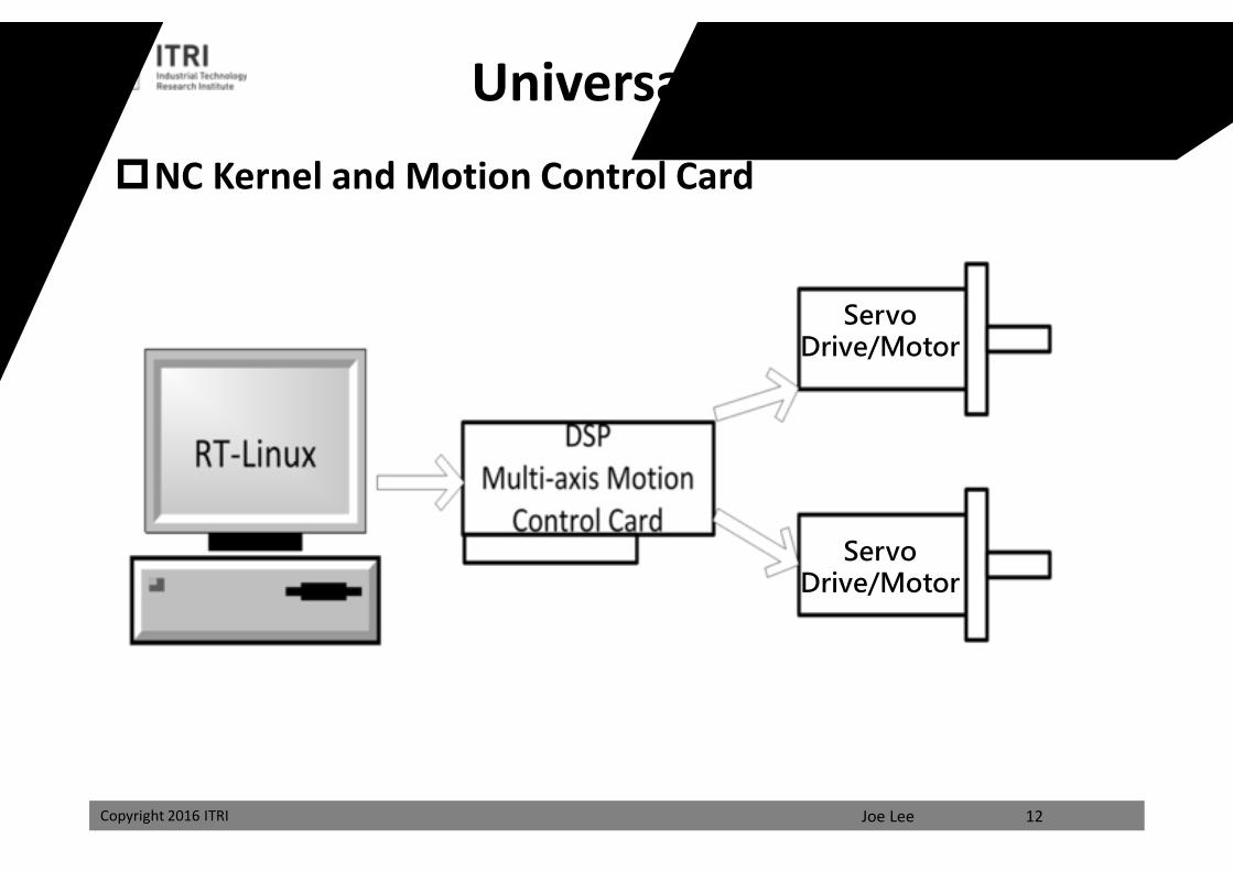
Universal Controller
Servo Drive/Motor
NC Kernel and Motion Control Card
12
Servo Drive/Motor
課程講義
禁止轉載
Joe LeeCopyright 2016 ITRI
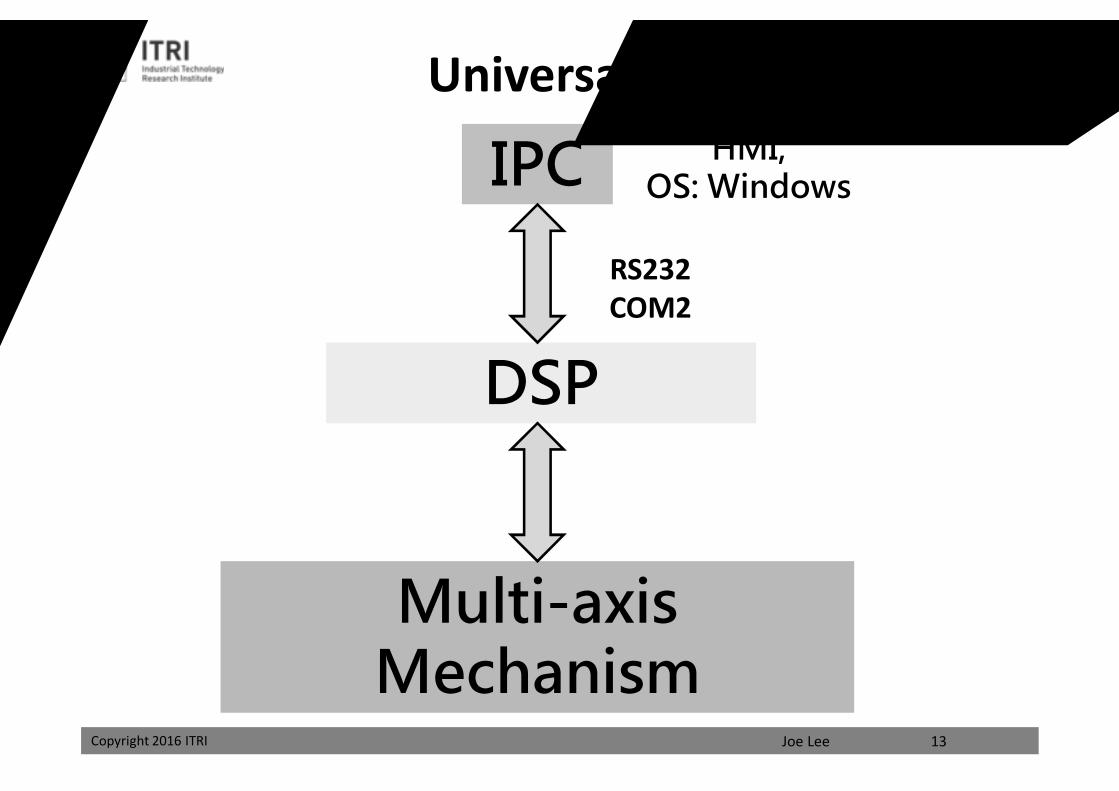
IPC
Multi-axis Mechanism
DSP
RS232COM2
HMI,OS: Windows
13
Universal Controller
課程講義
禁止轉載
Joe LeeCopyright 2016 ITRI
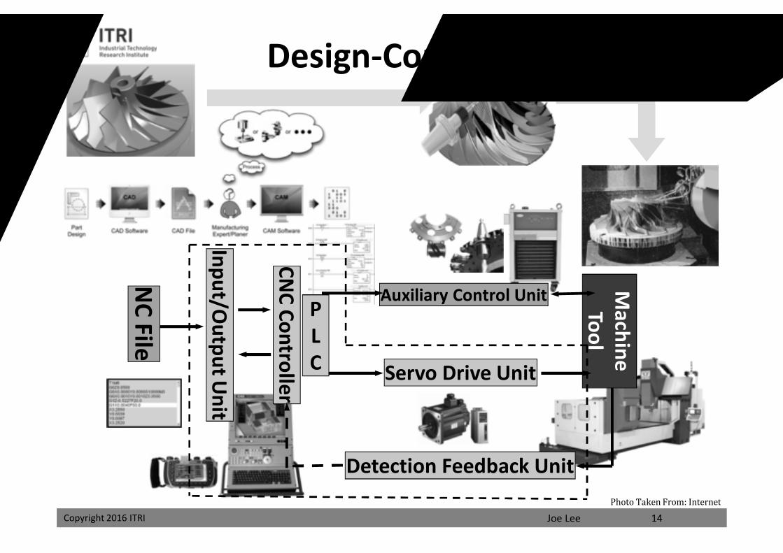
Design-Control-Machining
NC File
Input/OutputU
nit
CNC Controller
Auxiliary Control Unit
Servo Drive Unit
Detection Feedback Unit
Machine Tool
PLC
14Photo Taken From: Internet
課程講義
禁止轉載
Joe LeeCopyright 2016 ITRI
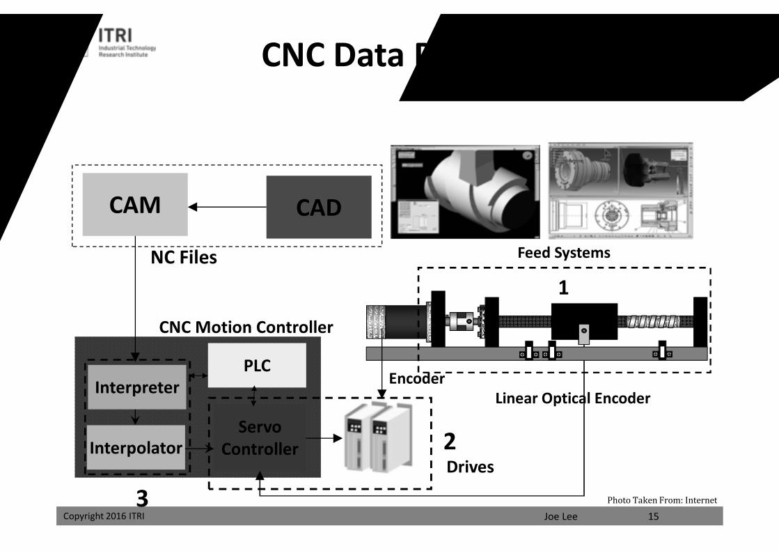
CADCAM
InterpolatorServo
Controller
NC Files Feed Systems
CNC Motion Controller
EncoderInterpreter Linear Optical Encoder
1
2
3
PLC
Drives
15Photo Taken From: Internet
CNC Data Processing Chain
課程講義
禁止轉載
Joe LeeCopyright 2016 ITRI Copyright 2016 ITRI
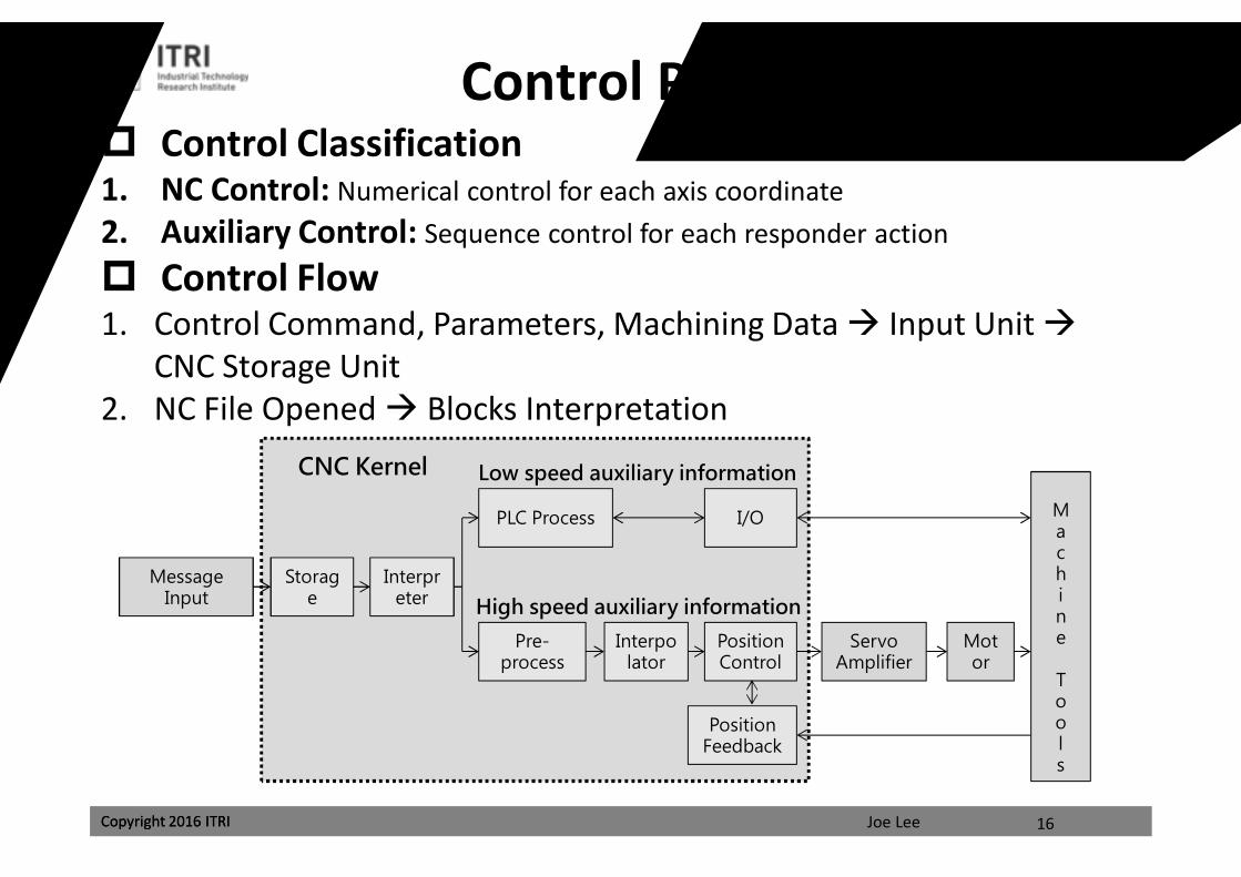
Control Process Design Control Classification1. NC Control: Numerical control for each axis coordinate2. Auxiliary Control: Sequence control for each responder action
Control Flow1. Control Command, Parameters, Machining Data Input Unit
CNC Storage Unit2. NC File Opened Blocks Interpretation
16
Message Input
Storage
Interpreter
Pre-process
PLC Process
Position Control
I/O
Servo Amplifier
Interpolator
PositionFeedback
Motor
Machine
Tools
CNC Kernel Low speed auxiliary information
High speed auxiliary information
課程講義
禁止轉載
Joe LeeCopyright 2016 ITRI Copyright 2016 ITRI
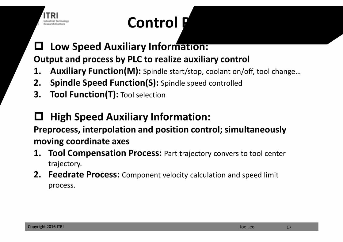
Low Speed Auxiliary Information:Output and process by PLC to realize auxiliary control1. Auxiliary Function(M): Spindle start/stop, coolant on/off, tool change…2. Spindle Speed Function(S): Spindle speed controlled3. Tool Function(T): Tool selection
High Speed Auxiliary Information:Preprocess, interpolation and position control; simultaneously moving coordinate axes1. Tool Compensation Process: Part trajectory convers to tool center
trajectory.2. Feedrate Process: Component velocity calculation and speed limit
process.
17
Control Process Design
課程講義
禁止轉載
Joe LeeCopyright 2016 ITRI Copyright 2016 ITRI
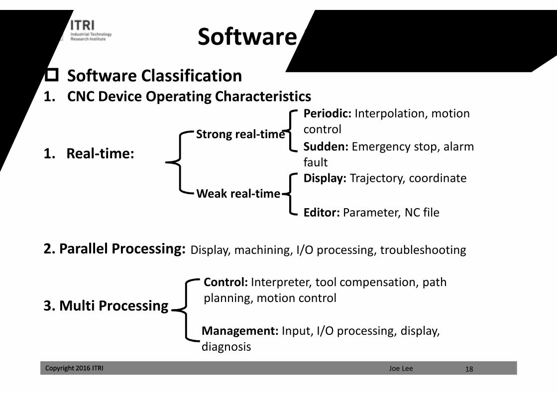
Software System Design Software Classification1. CNC Device Operating Characteristics
1. Real-time:
2. Parallel Processing:
3. Multi Processing
Strong real-time
Weak real-time
Periodic: Interpolation, motion controlSudden: Emergency stop, alarm faultDisplay: Trajectory, coordinate
Editor: Parameter, NC file
Display, machining, I/O processing, troubleshooting
Control: Interpreter, tool compensation, path planning, motion control
Management: Input, I/O processing, display, diagnosis
18
課程講義
禁止轉載
Joe LeeCopyright 2016 ITRI Copyright 2016 ITRI
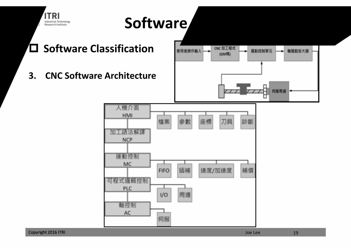
Software Classification
3. CNC Software Architecture
19
Software System Design
課程講義
禁止轉載
Joe LeeCopyright 2016 ITRI
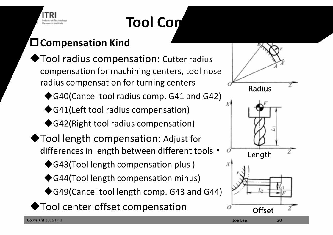
Tool CompensationCompensation KindTool radius compensation: Cutter radius
compensation for machining centers, tool nose radius compensation for turning centersG40(Cancel tool radius comp. G41 and G42)G41(Left tool radius compensation)G42(Right tool radius compensation)
Tool length compensation: Adjust for differences in length between different tools。G43(Tool length compensation plus )G44(Tool length compensation minus)G49(Cancel tool length comp. G43 and G44)
Tool center offset compensation20
Radius
Length
Offset
課程講義
禁止轉載
Joe LeeCopyright 2016 ITRI
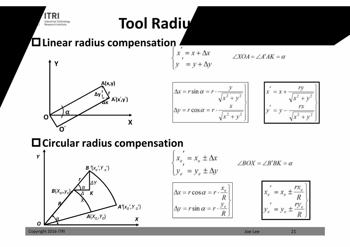
Linear radius compensation
Circular radius compensation
21
Y
X
A(x,y)
A’(x’,y’)∆y
∆x
O
O’
⍺
r
Y
O
r
X
A′(x0′,Y 0′)
B ′(xe′,Y e′)
B(Xe,,ye)
A(X0,,Y0)
K
R
ΔX
ΔY
α
α
Tool Radius Compensation
課程講義
禁止轉載
Joe LeeCopyright 2016 ITRI
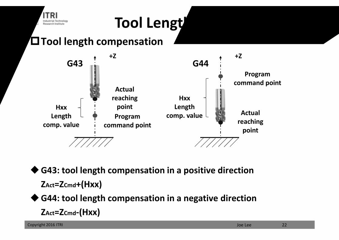
Tool length compensation
G43: tool length compensation in a positive directionZAct=ZCmd+(Hxx)
G44: tool length compensation in a negative directionZAct=ZCmd-(Hxx)
22
HxxLength
comp. value
G43
Actual reaching
pointProgram
command point
+Z
HxxLength
comp. value
G44+Z
Tool Length Compensation
Actual reaching
point
Program command point課程講義
禁止轉載
Joe LeeCopyright 2016 ITRI
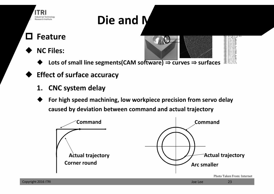
Feature NC Files:
Lots of small line segments(CAM software) ⇒ curves ⇒ surfaces
Effect of surface accuracy
1. CNC system delay For high speed machining, low workpiece precision from servo delay
caused by deviation between command and actual trajectory
Die and Mold Machining
Command
Actual trajectoryCorner round Arc smaller
23
Actual trajectory
Command
Photo Taken From: Internet
課程講義
禁止轉載
Joe LeeCopyright 2016 ITRI
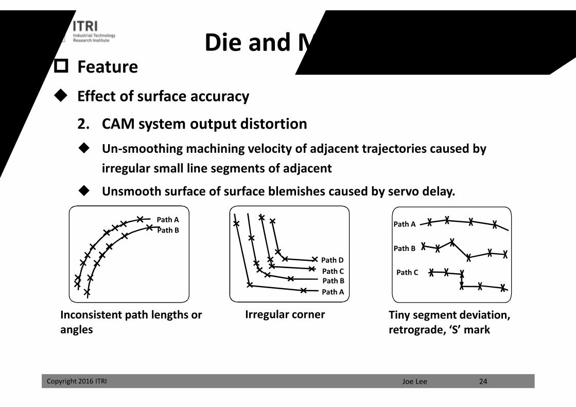
Feature Effect of surface accuracy
2. CAM system output distortion Un-smoothing machining velocity of adjacent trajectories caused by
irregular small line segments of adjacent
Unsmooth surface of surface blemishes caused by servo delay.
Tiny segment deviation, retrograde, ‘S’ mark
Irregular corner
Path BPath A
Inconsistent path lengths or angles
24
Die and Mold Machining
Path APath BPath CPath D
Path A
Path B
Path C
課程講義
禁止轉載

Joe LeeCopyright 2016 ITRI
Precision Motion CommandCoordinate movement for desired motion AxesGeneration and interpolationInterpolator: trajectory planningContinuous machining path converted to coordinate movement
Output approximate coordinate movement every fixed time interval
25
ퟏ∆풕 2∆풕 ퟑ∆풕 ퟒ∆풕 ퟓ∆풕 ퟔ∆풕 7∆풕 ퟖ∆풕
Motor rotation amount휽(풕) Target trajectory
The target trajectory is
assumed to be piecewise linear
with some
課程講義
禁止轉載
Joe LeeCopyright 2016 ITRI
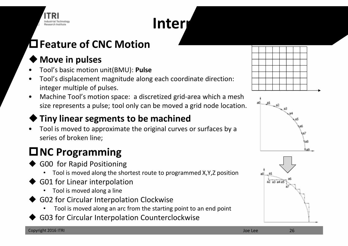
Feature of CNC MotionMove in pulses• Tool’s basic motion unit(BMU): Pulse• Tool’s displacement magnitude along each coordinate direction:
integer multiple of pulses.• Machine Tool’s motion space: a discretized grid-area which a mesh
size represents a pulse; tool only can be moved a grid node location.
Tiny linear segments to be machined• Tool is moved to approximate the original curves or surfaces by a
series of broken line;
NC Programming G00 for Rapid Positioning
• Tool is moved along the shortest route to programmed X,Y,Z position G01 for Linear interpolation
• Tool is moved along a line G02 for Circular Interpolation Clockwise
• Tool is moved along an arc from the starting point to an end point G03 for Circular Interpolation Counterclockwise
Interpolation
26
課程講義
禁止轉載
Joe LeeCopyright 2016 ITRI
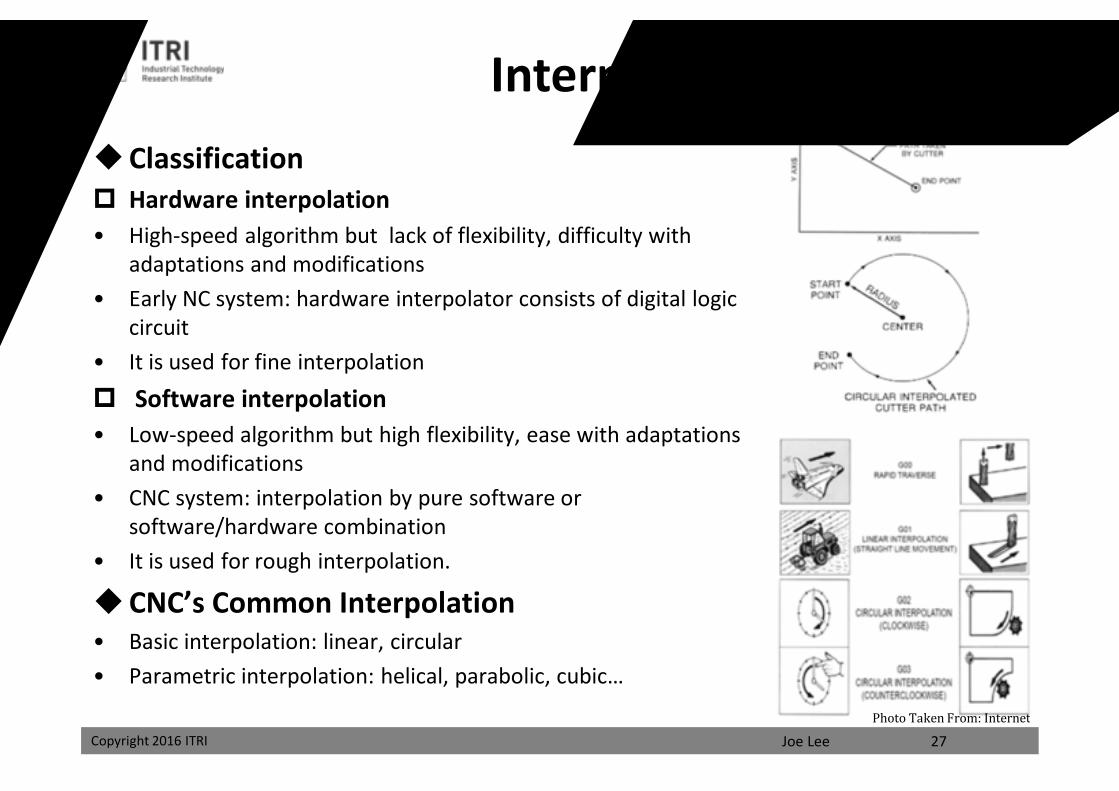
Classification Hardware interpolation• High-speed algorithm but lack of flexibility, difficulty with
adaptations and modifications• Early NC system: hardware interpolator consists of digital logic
circuit• It is used for fine interpolation Software interpolation• Low-speed algorithm but high flexibility, ease with adaptations
and modifications• CNC system: interpolation by pure software or
software/hardware combination• It is used for rough interpolation.
CNC’s Common Interpolation• Basic interpolation: linear, circular• Parametric interpolation: helical, parabolic, cubic…
Interpolation
27Photo Taken From: Internet
課程講義
禁止轉載
Joe LeeCopyright 2016 ITRI
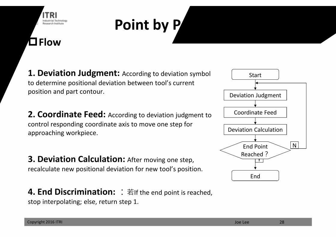
Point by Point ComparisonFlow
1. Deviation Judgment: According to deviation symbol to determine positional deviation between tool’s current position and part contour.
2. Coordinate Feed: According to deviation judgment to control responding coordinate axis to move one step for approaching workpiece.
3. Deviation Calculation: After moving one step, recalculate new positional deviation for new tool’s position.
4. End Discrimination: :若If the end point is reached, stop interpolating; else, return step 1.
28
Y
Start
Deviation Judgment
Coordinate Feed
Deviation Calculation
End Point Reached?
End
N
課程講義
禁止轉載
Joe LeeCopyright 2016 ITRI
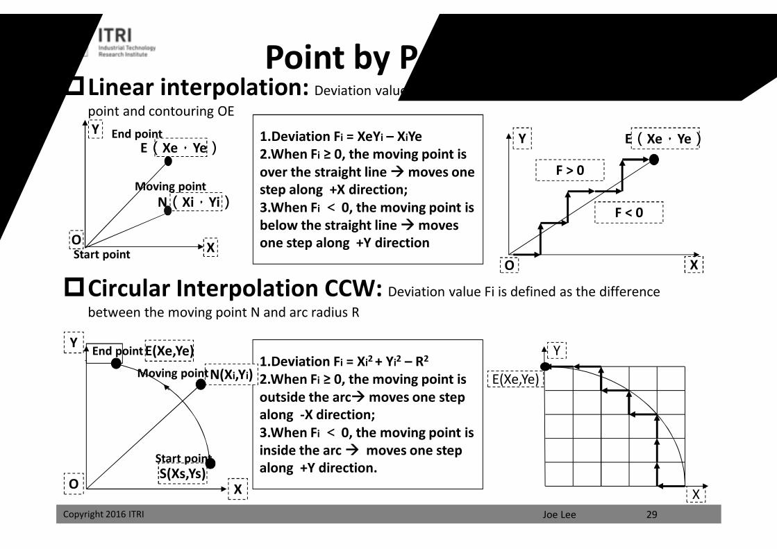
Linear interpolation: Deviation value Fi is defined as the distance between the moving point and contouring OE
Circular Interpolation CCW: Deviation value Fi is defined as the difference between the moving point N and arc radius R
29
O X
E(Xe,Ye)Y
F > 0
F < 0
O X
N(Xi,Yi)
E(Xe,Ye)Y
Start point
End point
Moving point
1.Deviation Fi = XeYi – XiYe2.When Fi ≥ 0, the moving point is over the straight line moves one step along +X direction;3.When Fi < 0, the moving point is below the straight line moves one step along +Y direction
1.Deviation Fi = Xi2 + Yi2 – R2
2.When Fi ≥ 0, the moving point is outside the arcmoves one step along -X direction;3.When Fi < 0, the moving point is inside the arc moves one step along +Y direction.
X
Y
E(Xe,Ye)N(Xi,Yi)
S(Xs,Ys)O X
Y E(Xe,Ye)
Start point
End point
Moving point
Point by Point Comparison
課程講義
禁止轉載
Joe LeeCopyright 2016 ITRI
Extended DDA InterpolationFeatureDigital Differential Analyzer(DDA)
• solves equations by numerical methods• a kind of increment algorithm• the value of x, y and z in next step will by figured out after x, y and z in
previous step adds a small increment simultaneously and respectively.• high precision machining but simple algorithm• calculation of tool’s displacement along with coordinates to make tool is
moved along the machining trajectory.• computing speed fast• the distribution of the controller pulse overflow is more uniform• easy to implement multi-axis moving simultaneously and complex multi-axis
independent variable space curve interpolation• the most commonly used in numerical contouring control system
30
課程講義
禁止轉載
Joe LeeCopyright 2016 ITRI
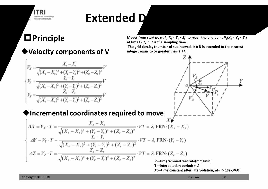
Principle
31
Moves from start point Ps(Xs,Ys,Zs) to reach the end point Pe(Xe,Ye,Ze) at time t= TI 。 T is the sampling time.The grid density (number of subintervals N): N is rounded to the nearest integer, equal to or greater than TI /T.Velocity components of V
Incremental coordinates required to move
V—Programmed feedrate(mm/min)T—Interpolation period(ms)λt—time constant after interpolation, λt=T×10e-3/60。
Extended DDA Interpolation
課程講義
禁止轉載
Joe LeeCopyright 2016 ITRI
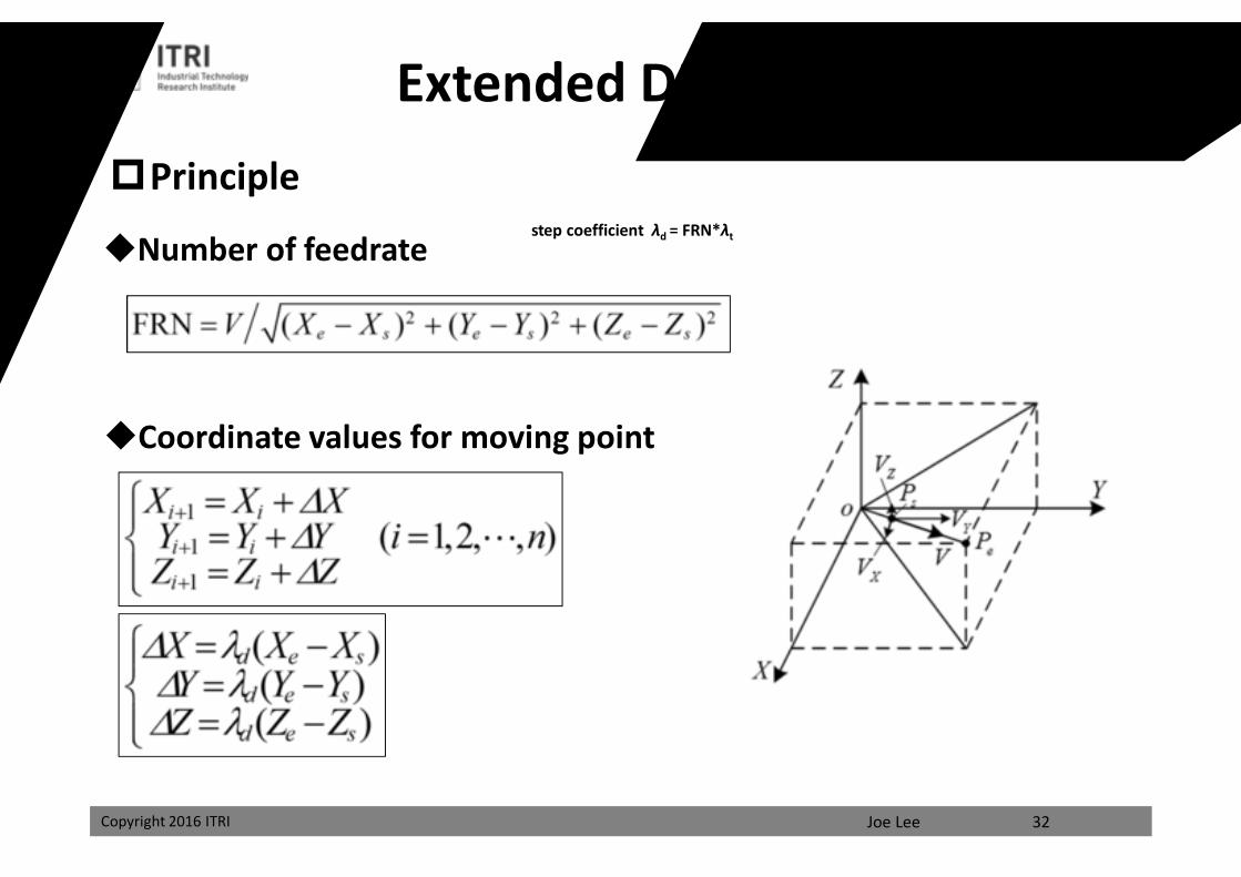
Principle
32
Number of feedrate
Coordinate values for moving point
step coefficient λd = FRN*λt
Extended DDA Interpolation
課程講義
禁止轉載
Joe LeeCopyright 2016 ITRI
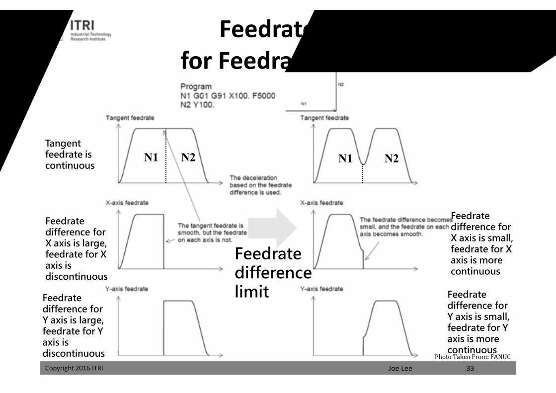
N1 N1 N2N2
33
Feedrate Design for Feedrate Difference
Tangent feedrate iscontinuous
Feedrate difference for X axis is large, feedrate for X axis is discontinuous
Feedrate difference limitFeedrate
difference for Y axis is large, feedrate for Y axis is discontinuous
Feedrate difference for X axis is small, feedrate for X axis is more continuous
Feedrate difference for Y axis is small, feedrate for Y axis is more continuous
Photo Taken From: FANUC
課程講義
禁止轉載
Joe LeeCopyright 2016 ITRI
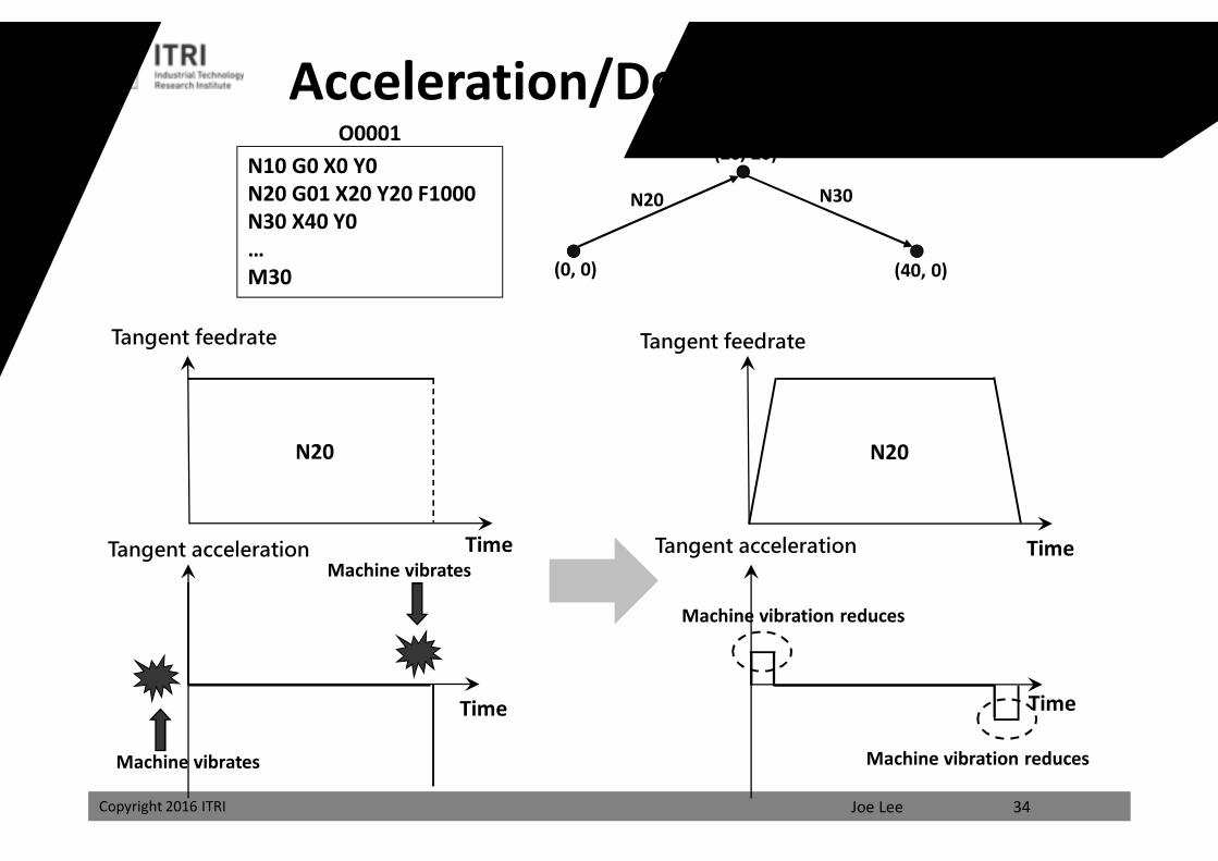
Acceleration/Deceleration DesignN10 G0 X0 Y0N20 G01 X20 Y20 F1000N30 X40 Y0…M30
O0001
(0, 0)
(20, 20)
(40, 0)
N20 N30
Time
N20
Machine vibrates
N20
34
Tangent feedrate Tangent feedrate
Tangent acceleration Tangent acceleration
Machine vibrates
Machine vibration reduces
Machine vibration reduces
Time
Time
Time
課程講義
禁止轉載
Joe LeeCopyright 2016 ITRI
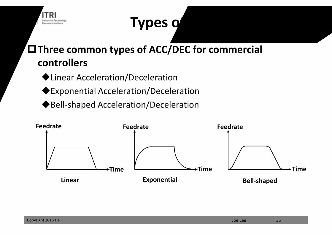
Types of ACC/DEC
Three common types of ACC/DEC for commercial controllersLinear Acceleration/DecelerationExponential Acceleration/DecelerationBell-shaped Acceleration/Deceleration
Time
Feedrate
ExponentialLinear Bell-shaped
35
Feedrate Feedrate
Time Time
課程講義
禁止轉載
Joe LeeCopyright 2016 ITRI
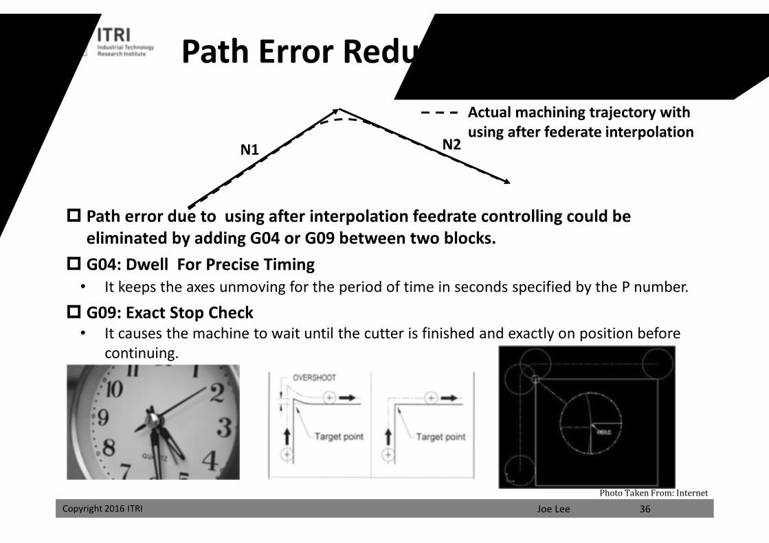
Path Error Reduction with G-CodeDesired machining trajectoryActual machining trajectory with using after federate interpolation
Path error due to using after interpolation feedrate controlling could be eliminated by adding G04 or G09 between two blocks.
G04: Dwell For Precise Timing• It keeps the axes unmoving for the period of time in seconds specified by the P number.
G09: Exact Stop Check • It causes the machine to wait until the cutter is finished and exactly on position before
continuing.
N2N1
36Photo Taken From: Internet
課程講義
禁止轉載
Joe LeeCopyright 2016 ITRI
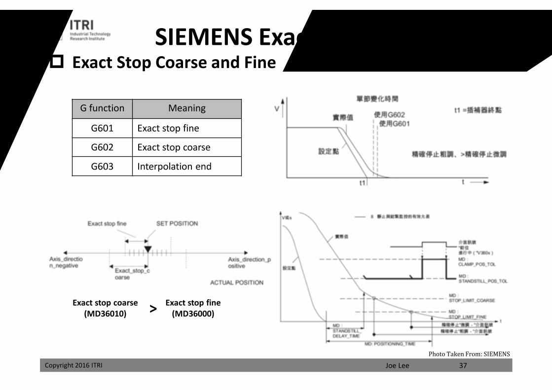
SIEMENS Exact Stop Function
G function Meaning
G601 Exact stop fine
G602 Exact stop coarse
G603 Interpolation end
Exact stop coarse(MD36010)
Exact stop fine(MD36000)>
37
Exact Stop Coarse and Fine
Photo Taken From: SIEMENS
課程講義
禁止轉載
Joe LeeCopyright 2016 ITRI
N1
N2
N3 N4
N5N6 N7
N8
N1 N2 N3 N4 N5 N6 N7 N8 Time
Feedrate
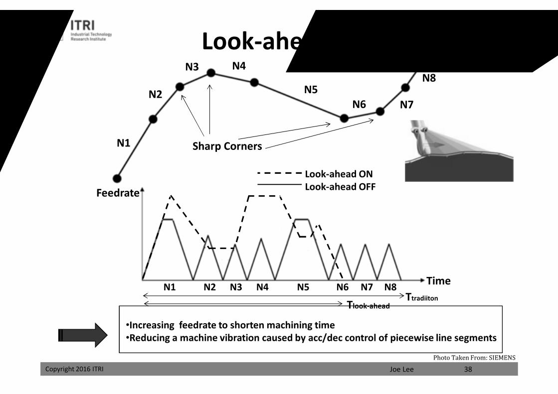
Look-ahead Function
•Increasing feedrate to shorten machining time•Reducing a machine vibration caused by acc/dec control of piecewise line segments
38
Look-ahead ONLook-ahead OFF
Sharp Corners
TtradiitonTlook-ahead
Photo Taken From: SIEMENS
課程講義
禁止轉載
Joe LeeCopyright 2016 ITRI
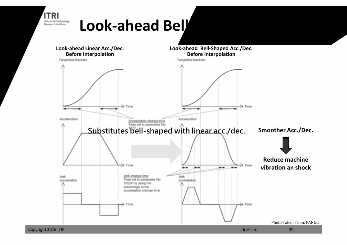
Look-ahead Bell-shaped Acc./Dec.Look-ahead Linear Acc./Dec.
Before InterpolationLook-ahead Bell-Shaped Acc./Dec.
Before Interpolation
Smoother Acc./Dec.
Reduce machine vibration an shock
39
Substitutes bell-shaped with linear acc./dec.
Photo Taken From: FANUC
課程講義
禁止轉載
Joe LeeCopyright 2016 ITRI
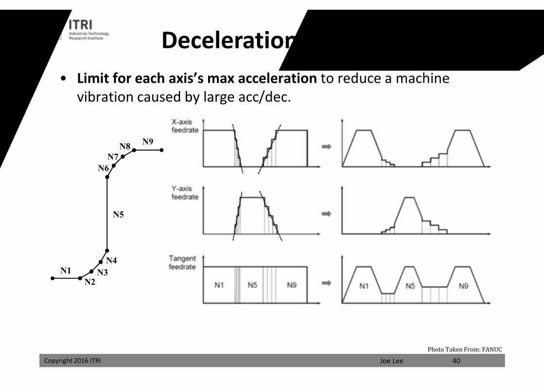
Deceleration by Acceleration
N8N7
N6
N1N2
N3N4
N5
N9
• Limit for each axis’s max acceleration to reduce a machine vibration caused by large acc/dec.
40Photo Taken From: FANUC
課程講義
禁止轉載
Joe LeeCopyright 2016 ITRI
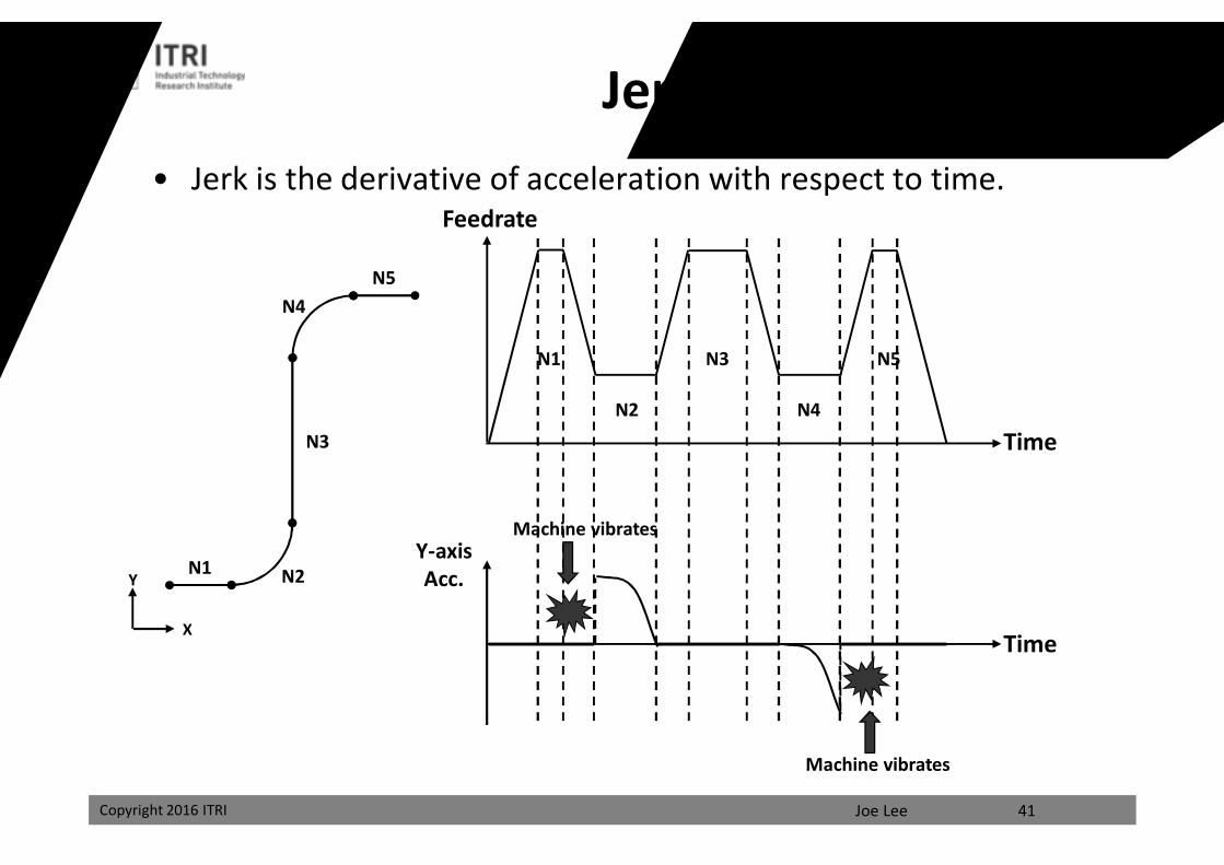
• Jerk is the derivative of acceleration with respect to time.
N4
N1 N2
N3
N5
X
Y
N1
N2
N3
N4
N5
Feedrate
Time
Y-axisAcc.
Time
Machine vibrates
Machine vibrates
41
Jerk Plan
課程講義
禁止轉載
Joe LeeCopyright 2016 ITRI
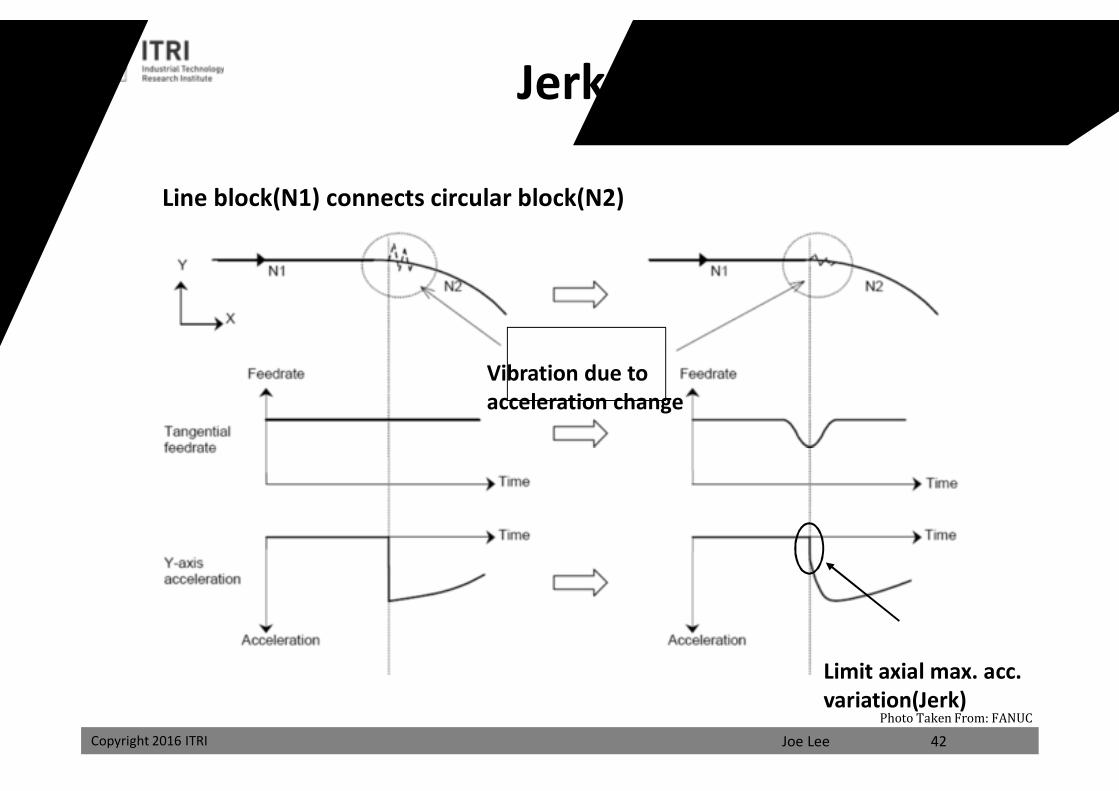
Line block(N1) connects circular block(N2)
Limit axial max. acc. variation(Jerk)
42
Jerk Control
Vibration due to acceleration change
Photo Taken From: FANUC
課程講義
禁止轉載
Joe LeeCopyright 2016 ITRI 43
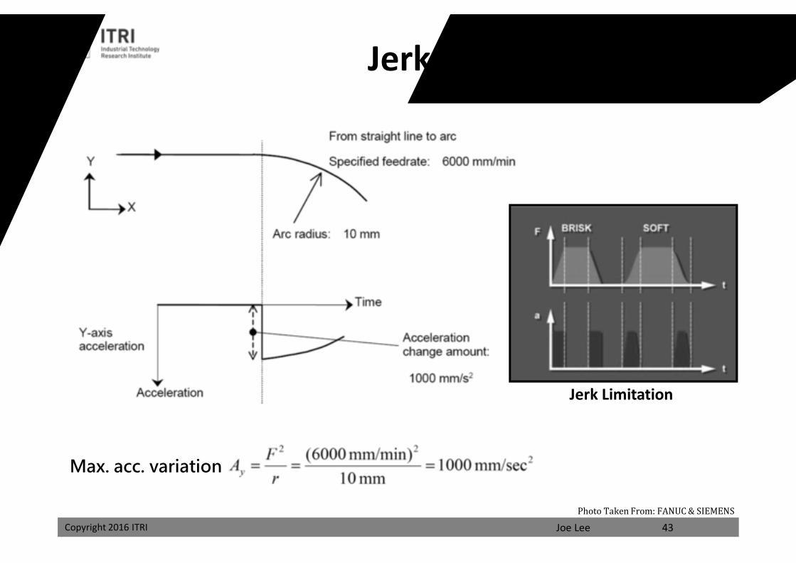
Jerk Control
Max. acc. variation
Jerk Limitation
Photo Taken From: FANUC & SIEMENS
課程講義
禁止轉載
Joe LeeCopyright 2016 ITRI
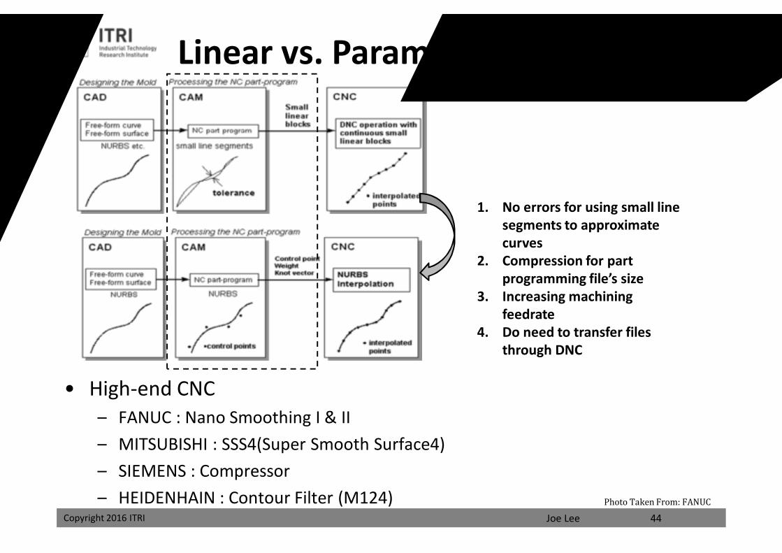
Linear vs. Parametric Interpolation
• High-end CNC– FANUC : Nano Smoothing I & II – MITSUBISHI : SSS4(Super Smooth Surface4)– SIEMENS : Compressor– HEIDENHAIN : Contour Filter (M124)
44
1. No errors for using small line segments to approximate curves
2. Compression for part programming file’s size
3. Increasing machining feedrate
4. Do need to transfer files through DNC
Photo Taken From: FANUC
課程講義
禁止轉載
Joe LeeCopyright 2016 ITRI
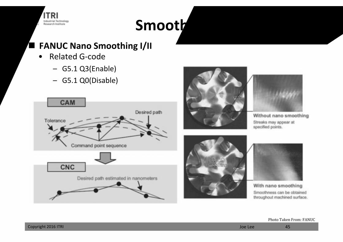
FANUC Nano Smoothing I/II• Related G-code
– G5.1 Q3(Enable)– G5.1 Q0(Disable)
45
Smoothing Control
Photo Taken From: FANUC
課程講義
禁止轉載
Joe LeeCopyright 2016 ITRI
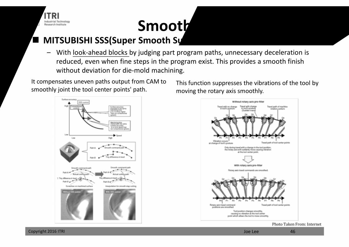
MITSUBISHI SSS(Super Smooth Surface)– With look-ahead blocks by judging part program paths, unnecessary deceleration is
reduced, even when fine steps in the program exist. This provides a smooth finish without deviation for die-mold machining.
46
It compensates uneven paths output from CAM to smoothly joint the tool center points' path.
This function suppresses the vibrations of the tool by moving the rotary axis smoothly.
Smoothing Control
Photo Taken From: Internet
課程講義
禁止轉載
Joe LeeCopyright 2016 ITRI 47Photo Taken From: MITSUBISHI
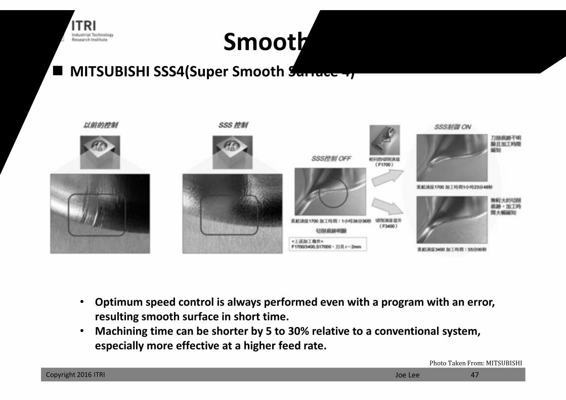
MITSUBISHI SSS4(Super Smooth Surface 4)
Smoothing Control
• Optimum speed control is always performed even with a program with an error, resulting smooth surface in short time.
• Machining time can be shorter by 5 to 30% relative to a conventional system, especially more effective at a higher feed rate.
課程講義
禁止轉載
Joe LeeCopyright 2016 ITRI
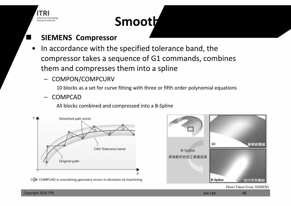
SIEMENS Compressor• In accordance with the specified tolerance band, the
compressor takes a sequence of G1 commands, combines them and compresses them into a spline – COMPON/COMPCURV
10 blocks as a set for curve fitting with three or fifth order polynomial equations
– COMPCADAll blocks combined and compressed into a B-Spline
48Photo Taken From: SIEMENS
Smoothing Control
課程講義
禁止轉載
Joe LeeCopyright 2016 ITRI
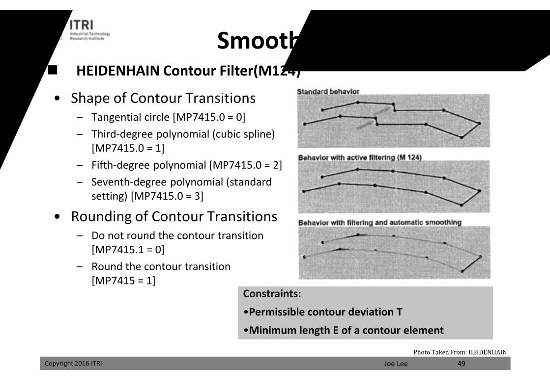
HEIDENHAIN Contour Filter(M124)
• Shape of Contour Transitions– Tangential circle [MP7415.0 = 0]– Third-degree polynomial (cubic spline)
[MP7415.0 = 1]– Fifth-degree polynomial [MP7415.0 = 2] – Seventh-degree polynomial (standard
setting) [MP7415.0 = 3]
• Rounding of Contour Transitions– Do not round the contour transition
[MP7415.1 = 0]– Round the contour transition
[MP7415 = 1]Constraints:•Permissible contour deviation T•Minimum length E of a contour element
49Photo Taken From: HEIDENHAIN
Smoothing Control
課程講義
禁止轉載
Joe LeeCopyright 2016 ITRI
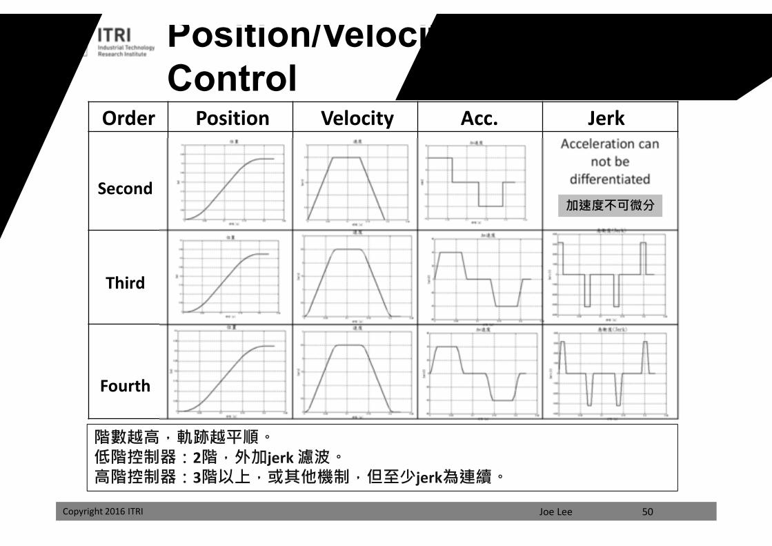
Acceleration can not be
differentiated
Position Velocity Acc. Jerk
Second
Third
Fourth
Order
階數越高,軌跡越平順。低階控制器:2階,外加jerk 濾波。高階控制器:3階以上,或其他機制,但至少jerk為連續。
Position/Velocity/Acc./Jerk Control
加速度不可微分
50
課程講義
禁止轉載
Joe LeeCopyright 2016 ITRI
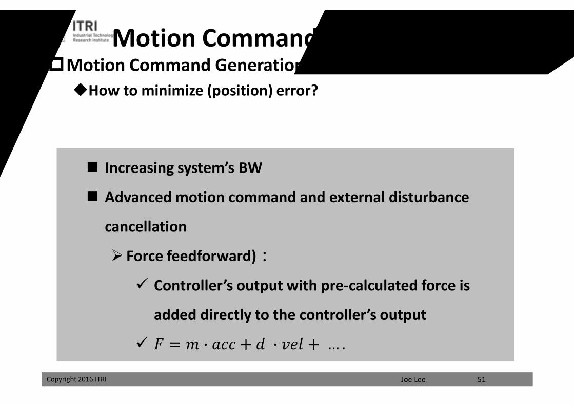
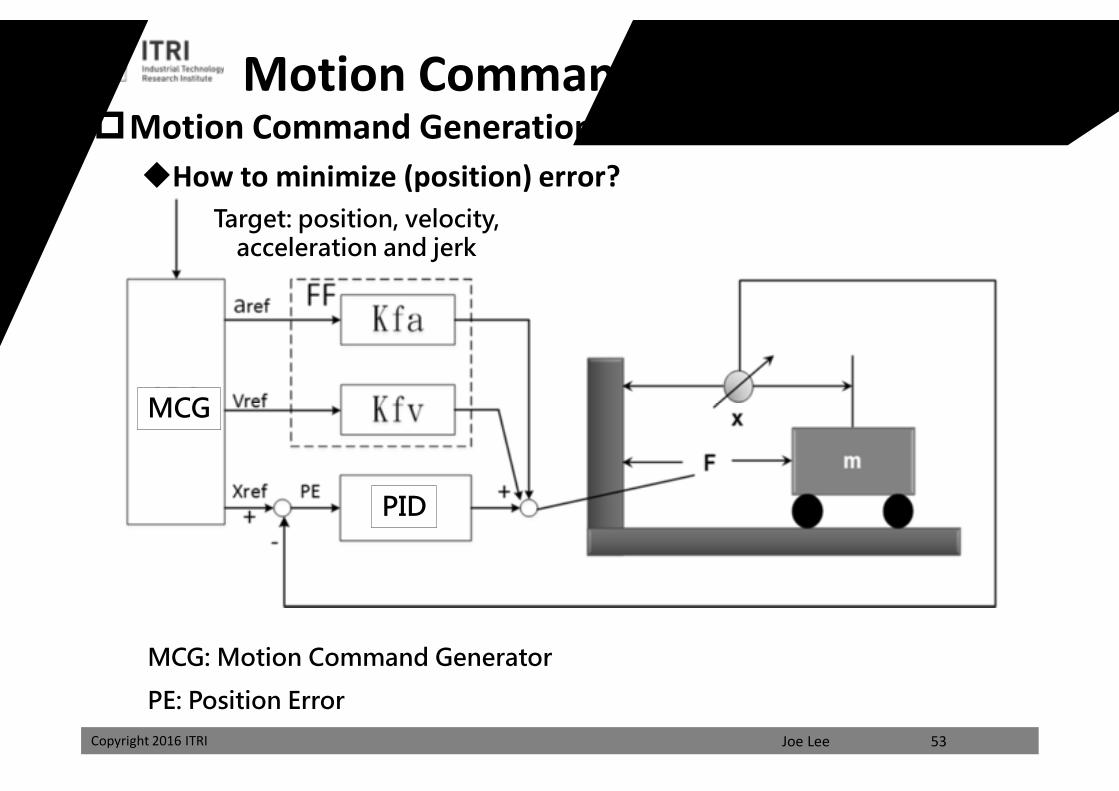
Motion Command GenerationHow to minimize (position) error?
Motion Command and Feedforward
Increasing system’s BW
Advanced motion command and external disturbance
cancellation
Force feedforward):
Controller’s output with pre-calculated force is
added directly to the controller’s output
퐹 = 푚 푎푐푐 + 푑 푣푒푙 + … .
51
課程講義
禁止轉載
Joe LeeCopyright 2016 ITRI
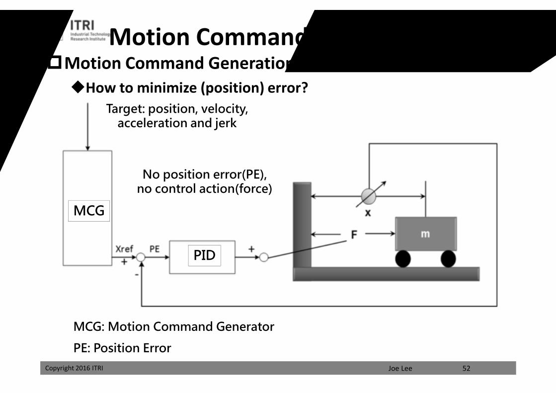
Motion Command GenerationHow to minimize (position) error?
Motion Command w/o Feedforward
MCG: Motion Command Generator
PE: Position Error
MCG
PID
Target: position, velocity, acceleration and jerk
No position error(PE),no control action(force)
52
課程講義
禁止轉載
Joe LeeCopyright 2016 ITRI
Motion Command GenerationHow to minimize (position) error?
Motion Command w/ Feedforward
MCG: Motion Command Generator
PE: Position Error
MCG
PID
Target: position, velocity, acceleration and jerk
53
課程講義
禁止轉載
Joe LeeCopyright 2016 ITRI
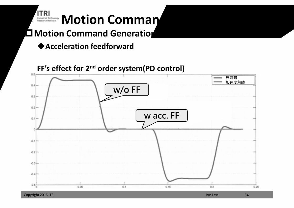
Motion Command GenerationAcceleration feedforward
Motion Command w/ Feedforward
無前饋加速度前饋
w/o FF
w acc. FF
FF’s effect for 2nd order system(PD control)
54
課程講義
禁止轉載
Joe LeeCopyright 2016 ITRI
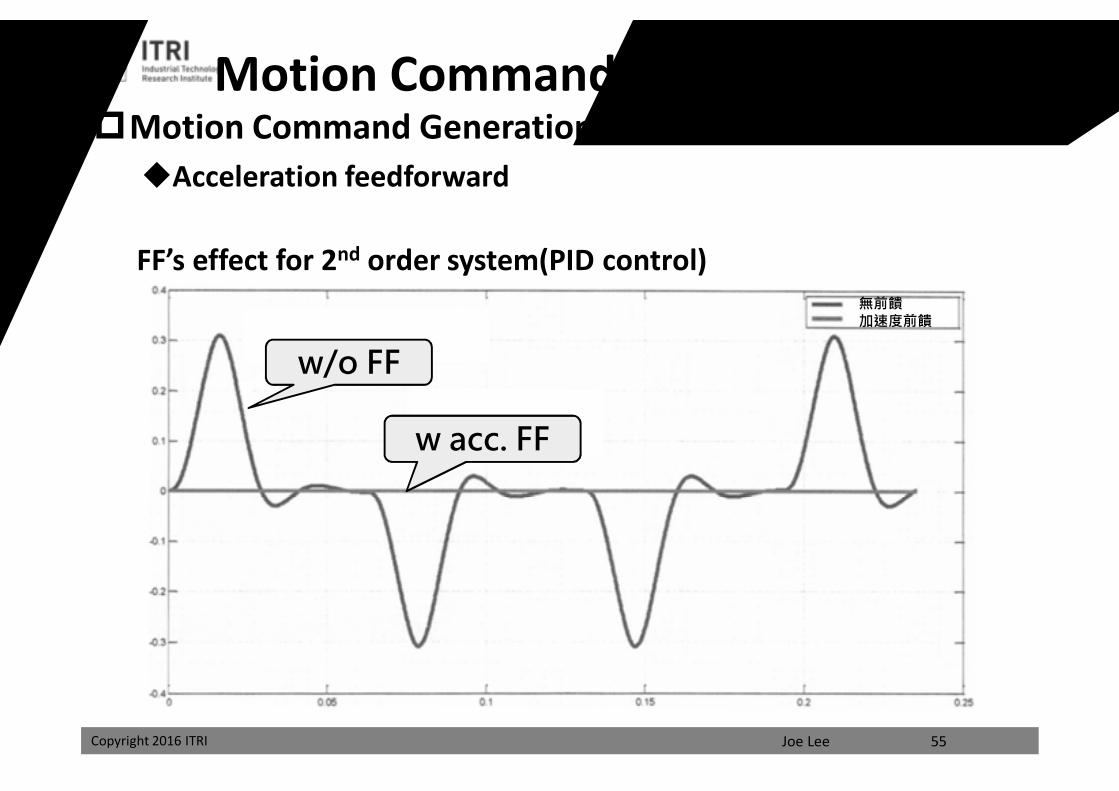
Motion Command w/ FeedforwardMotion Command GenerationAcceleration feedforward
無前饋加速度前饋
w/o FF
w acc. FF
FF’s effect for 2nd order system(PID control)
55
課程講義
禁止轉載
Joe LeeCopyright 2016 ITRI
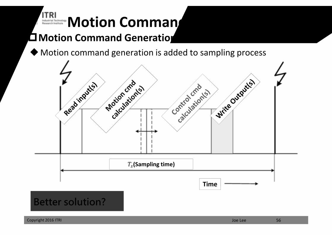
Motion Command GenerationMotion Command and Feedforward
Motion command generation is added to sampling process
Better solution?
Time
푇 (Sampling time)
56
課程講義
禁止轉載
Joe LeeCopyright 2016 ITRI
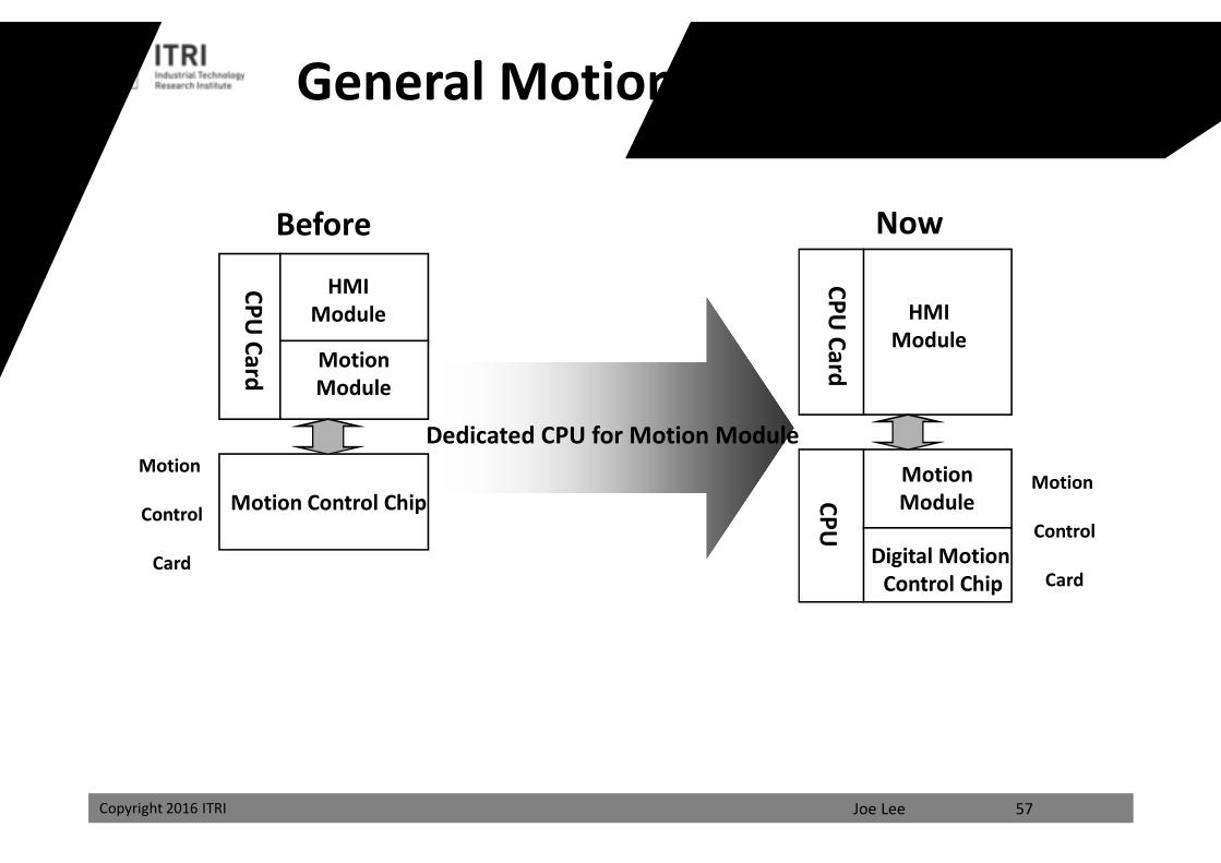
General Motion Control Platform
HMIModule
Motion Control Chip
CPUCard
Before
Motion
Control
Card
CPUCard
Now
HMIModule
MotionModule
MotionModuleCPU
Digital Motion Control Chip
Dedicated CPU for Motion Module
57
Motion
Control
Card
課程講義
禁止轉載
Joe LeeCopyright 2016 ITRI
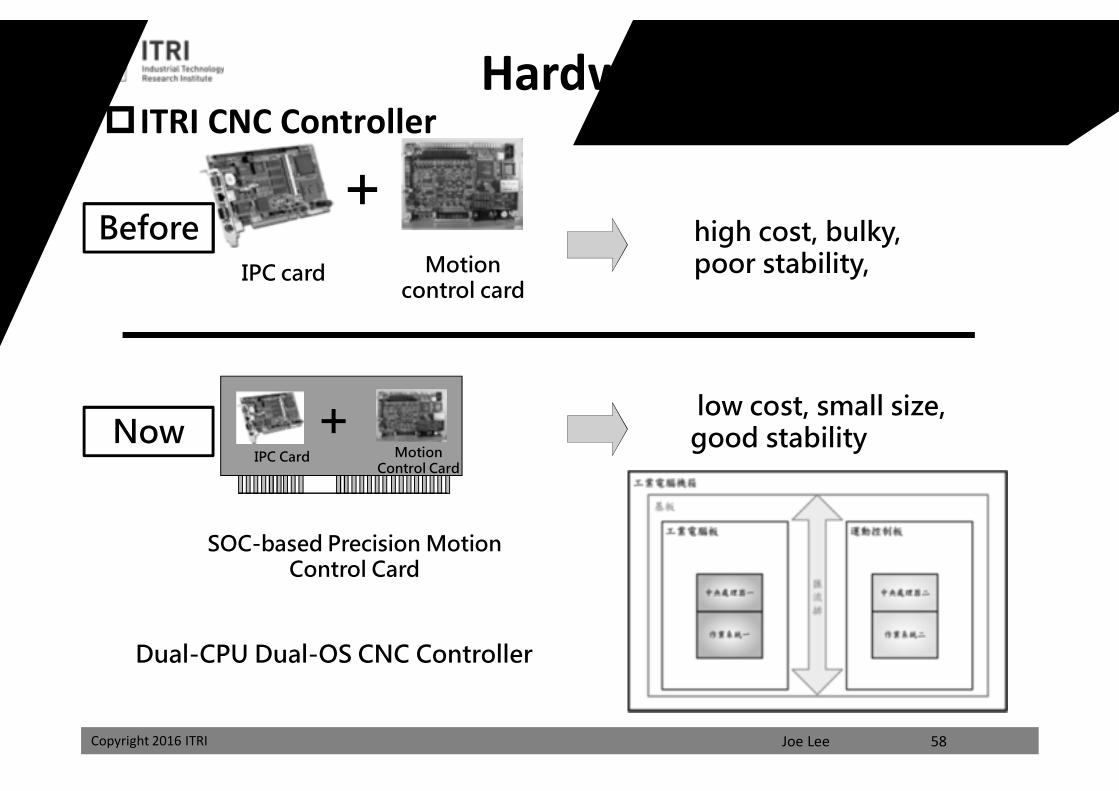
ITRI CNC ControllerHardware Design
high cost, bulky, poor stability,IPC card Motion
control card
+
IPC Card Motion Control Card
+
SOC-based Precision Motion Control Card
low cost, small size, good stability
Dual-CPU Dual-OS CNC Controller
Before
Now
58
課程講義
禁止轉載
Joe LeeCopyright 2016 ITRI
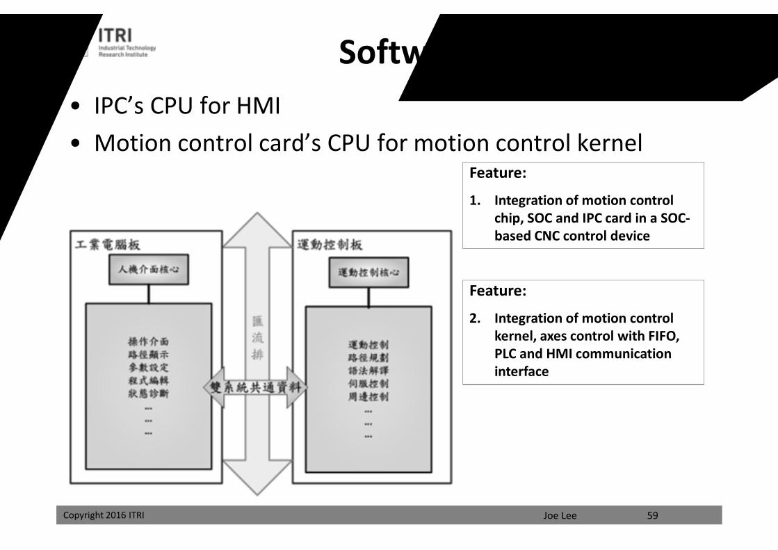
• IPC’s CPU for HMI• Motion control card’s CPU for motion control kernel
59
Software Design
Feature:
2. Integration of motion control kernel, axes control with FIFO, PLC and HMI communication interface
Feature:
1. Integration of motion control chip, SOC and IPC card in a SOC-based CNC control device課程講義
禁止轉載
Joe LeeCopyright 2016 ITRI
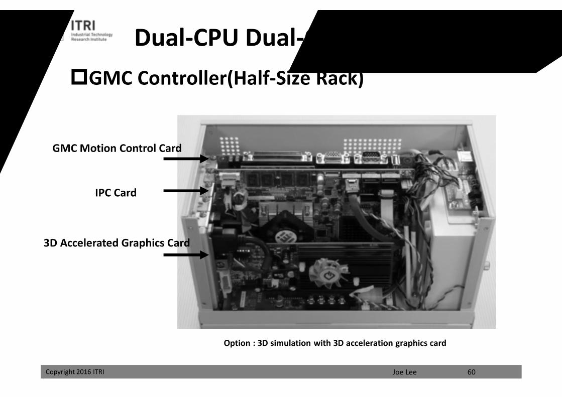
Dual-CPU Dual-OS CNC ControllerGMC Controller(Half-Size Rack)
GMC Motion Control Card
IPC Card
3D Accelerated Graphics Card
Option : 3D simulation with 3D acceleration graphics card
60
課程講義
禁止轉載
Joe LeeCopyright 2016 ITRI Copyright 2016 ITRI 61
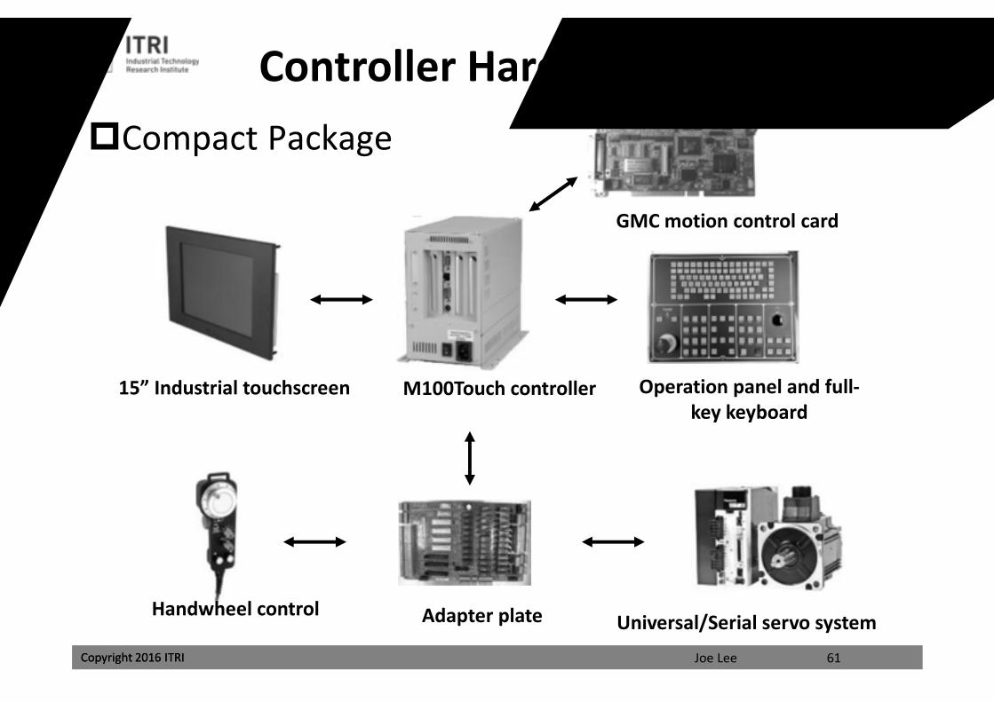
Controller Hardware ArchitectureCompact Package
15” Industrial touchscreen M100Touch controller Operation panel and full-key keyboard
Handwheel control Adapter plate Universal/Serial servo system
GMC motion control card課程講義
禁止轉載
Joe LeeCopyright 2016 ITRI 62
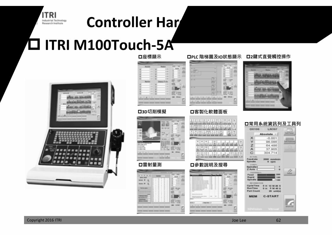
ITRI M100Touch-5A 座標顯示
3D切削模擬
2鍵式直覺觸控操作PLC 階梯圖及IO狀態顯示
客製化軟體面板
參數說明及搜尋雷射量測
常用系統資訊列及工具列
Controller Hardware Architecture
課程講義
禁止轉載
Joe LeeCopyright 2016 ITRI
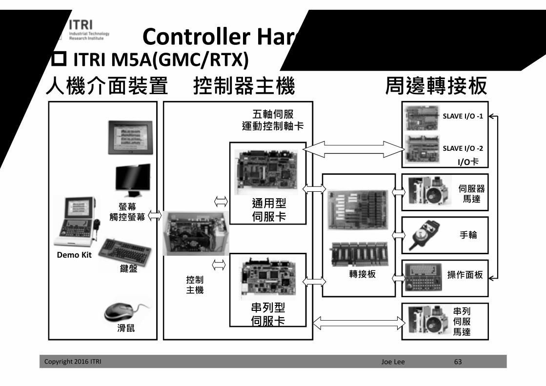
通用型伺服卡
串列型伺服卡
螢幕觸控螢幕
鍵盤
滑鼠
轉接板
I/O卡
伺服器馬達
控制主機
手輪
操作面板
串列伺服馬達
人機介面裝置 控制器主機五軸伺服
運動控制軸卡
周邊轉接板SLAVE I/O -1
SLAVE I/O -2
Demo Kit
63
ITRI M5A(GMC/RTX)Controller Hardware Architecture
課程講義
禁止轉載
Joe LeeCopyright 2016 ITRI 64
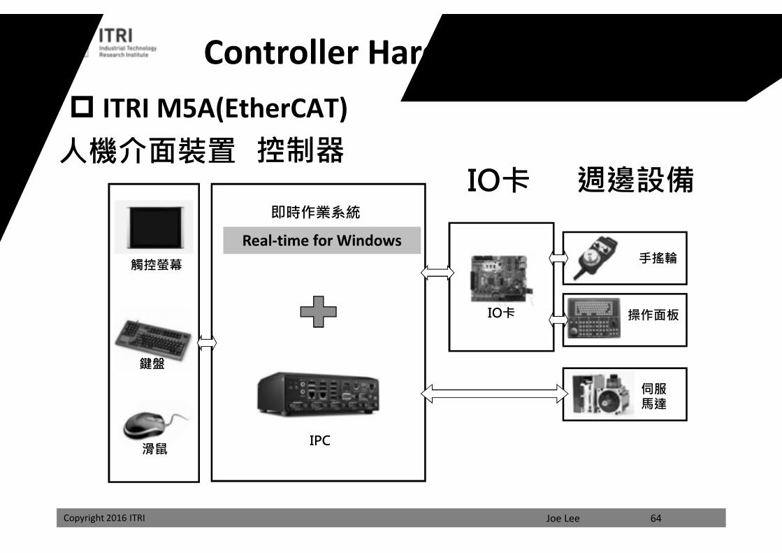
觸控螢幕
鍵盤
滑鼠
人機介面裝置
IPC
控制器
即時作業系統
IO卡
手搖輪
操作面板
伺服馬達
IO卡 週邊設備
ITRI M5A(EtherCAT)
Controller Hardware Architecture
Real-time for Windows課程講義
禁止轉載
Joe LeeCopyright 2016 ITRI
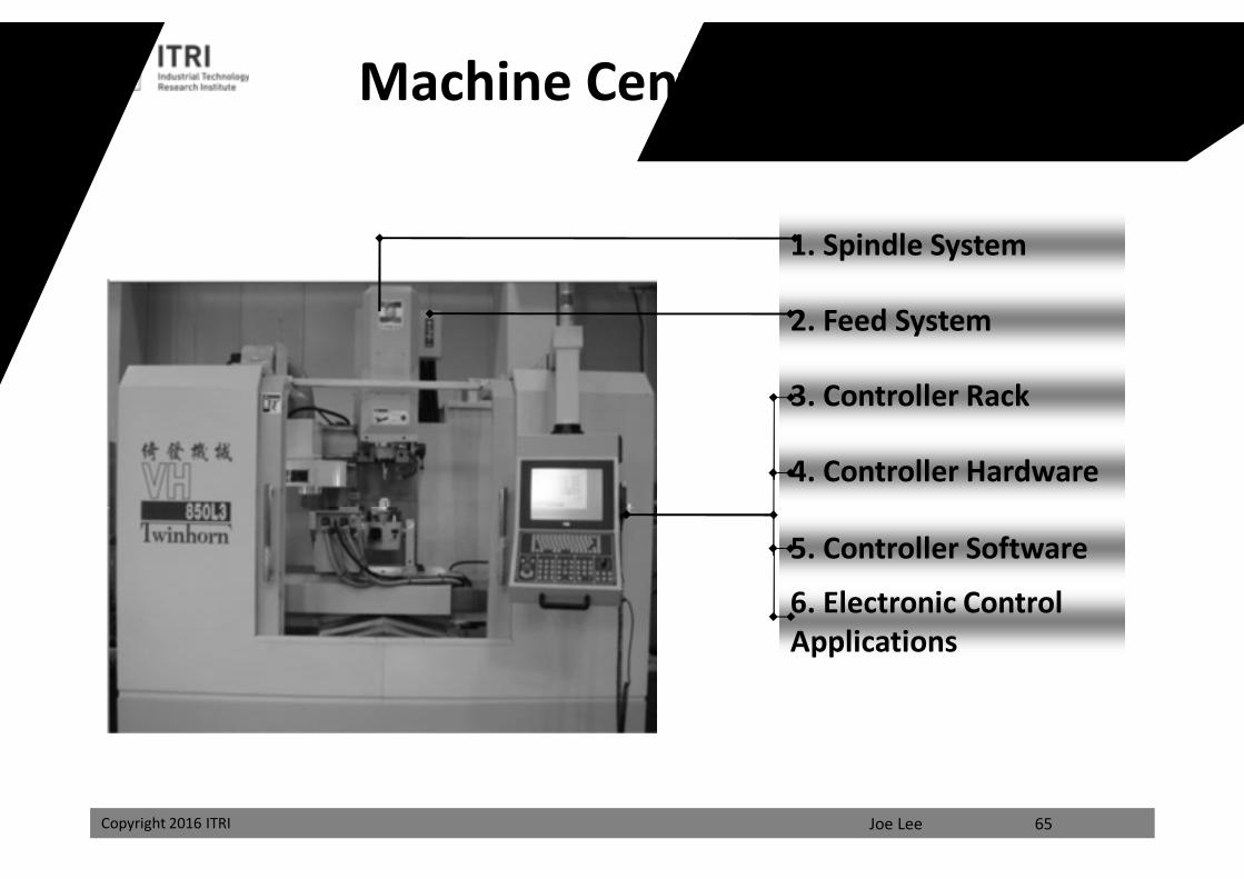
Machine Center Controller
1. Spindle System
2. Feed System
3. Controller Rack
4. Controller Hardware
5. Controller Software
6. Electronic Control Applications
65
課程講義
禁止轉載
Joe LeeCopyright 2016 ITRI Copyright 2016 ITRI 66
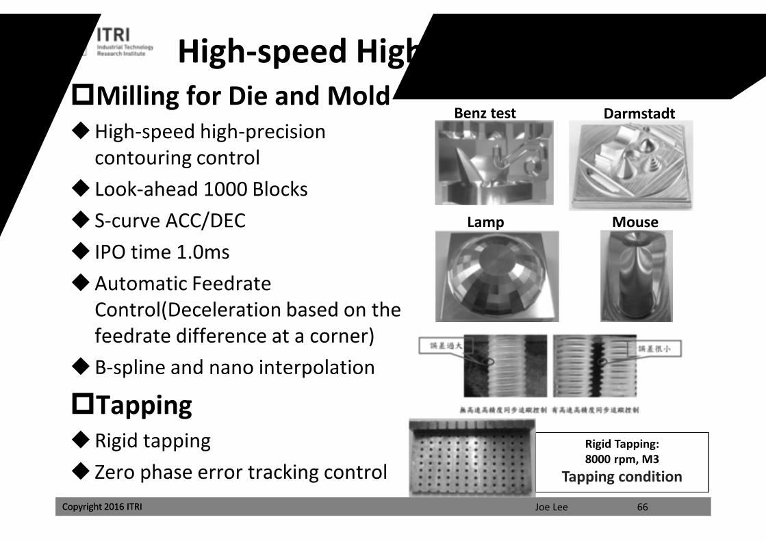
High-speed High-precision ControlMilling for Die and MoldHigh-speed high-precision
contouring control Look-ahead 1000 Blocks S-curve ACC/DEC IPO time 1.0msAutomatic Feedrate
Control(Deceleration based on the feedrate difference at a corner)
B-spline and nano interpolation
TappingRigid tapping Zero phase error tracking control
Benz test
Lamp
Darmstadt
Mouse
Rigid Tapping: 8000 rpm, M3
Tapping condition
課程講義
禁止轉載
Joe LeeCopyright 2016 ITRI Copyright 2016 ITRI
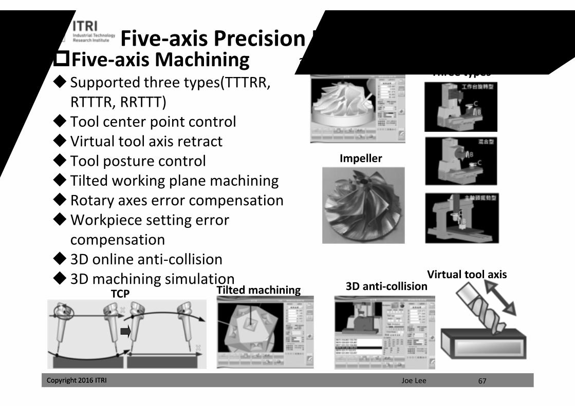
Five-axis Precision Interpolation ControlFive-axis Machining Supported three types(TTTRR,
RTTTR, RRTTT)Tool center point controlVirtual tool axis retractTool posture controlTilted working plane machiningRotary axes error compensationWorkpiece setting error
compensation3D online anti-collision3D machining simulation
TCP 3D anti-collisionVirtual tool axis
Impeller
Three types
67
3D machining simulation
Tilted machining
課程講義
禁止轉載
Joe LeeCopyright 2016 ITRI Copyright 2016 ITRI 68
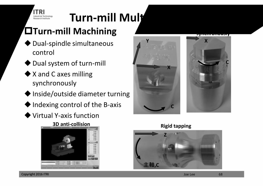
Turn-mill Multi-tasking ControlTurn-mill MachiningDual-spindle simultaneous
controlDual system of turn-millX and C axes milling
synchronously Inside/outside diameter turning Indexing control of the B-axisVirtual Y-axis function
X and C axes synchronously
C
XVirtual Y-axis
C
X
Y
Rigid tapping
主軸,C
Z
3D anti-collision
動力刀塔
尾座主軸
課程講義
禁止轉載
Joe LeeCopyright 2016 ITRI
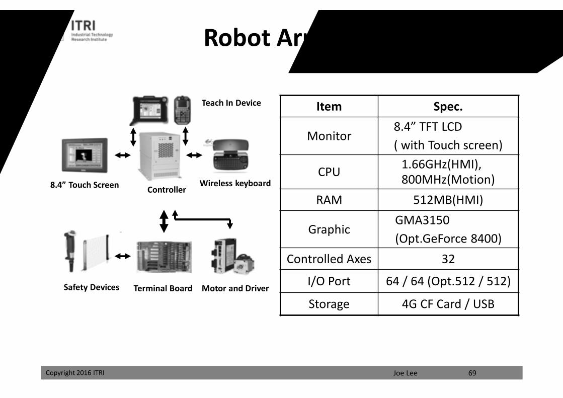
8.4” Touch Screen ControllerWireless keyboard
Safety Devices Terminal Board Motor and Driver
Item Spec.
Monitor8.4” TFT LCD( with Touch screen)
CPU 1.66GHz(HMI), 800MHz(Motion)
RAM 512MB(HMI)
GraphicGMA3150 (Opt.GeForce 8400)
Controlled Axes 32
I/O Port 64 / 64 (Opt.512 / 512)
Storage 4G CF Card / USB
Teach In Device
69
Robot Arm Controller
課程講義
禁止轉載
Joe LeeCopyright 2016 ITRI Copyright 2016 ITRI
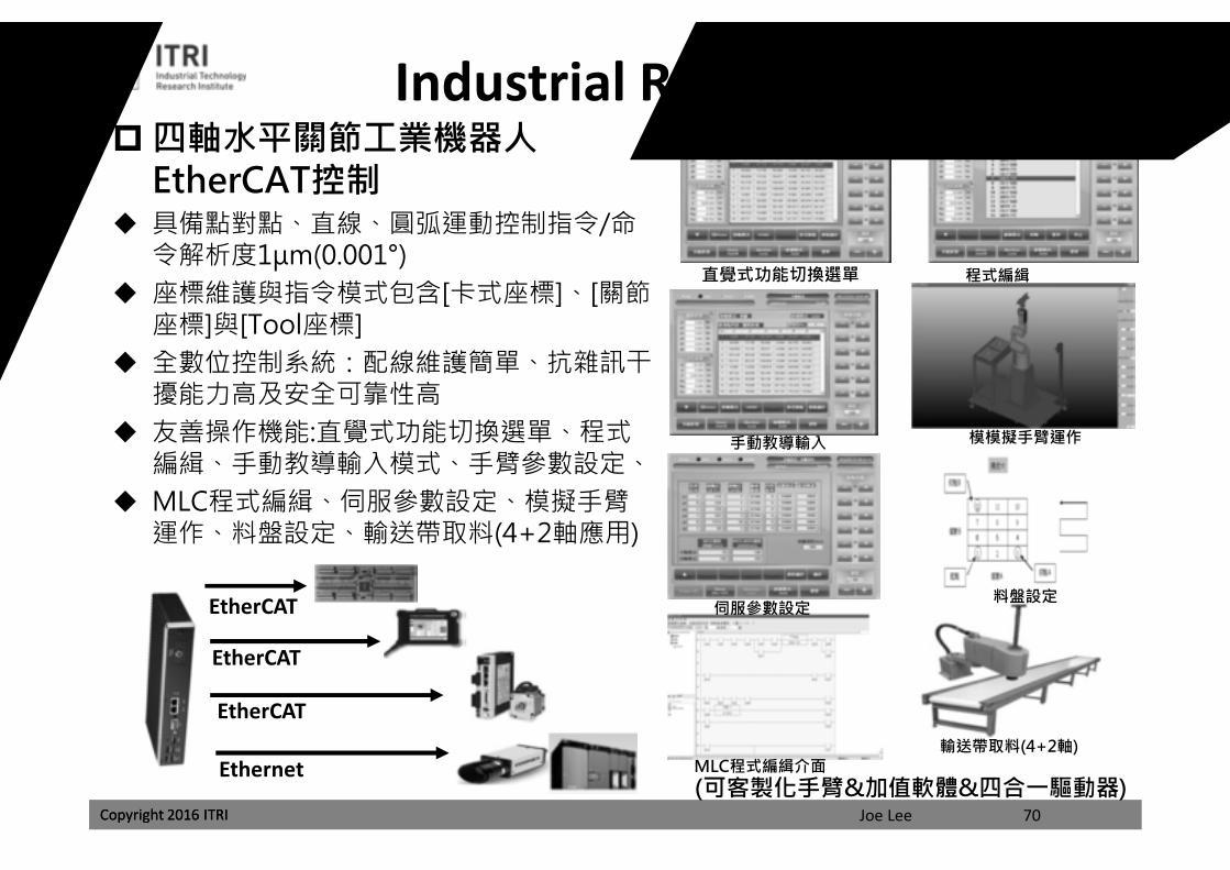
Industrial ROBOT Control四軸水平關節工業機器人
EtherCAT控制 具備點對點、直線、圓弧運動控制指令/命
令解析度1μm(0.001°) 座標維護與指令模式包含[卡式座標]、[關節
座標]與[Tool座標] 全數位控制系統:配線維護簡單、抗雜訊干
擾能力高及安全可靠性高 友善操作機能:直覺式功能切換選單、程式
編緝、手動教導輸入模式、手臂參數設定、 MLC程式編緝、伺服參數設定、模擬手臂
運作、料盤設定、輸送帶取料(4+2軸應用)
70(可客製化手臂&加值軟體&四合一驅動器)
EtherCAT
Ethernet
EtherCAT
EtherCAT
直覺式功能切換選單 程式編緝
手動教導輸入 模模擬手臂運作
伺服參數設定
MLC程式編緝介面
料盤設定
輸送帶取料(4+2軸)
課程講義
禁止轉載
Joe LeeCopyright 2016 ITRI Copyright 2016 ITRI
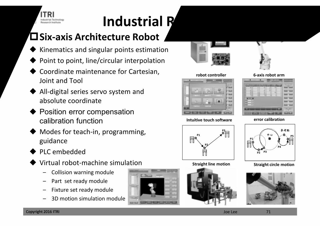
Industrial ROBOT ControlSix-axis Architecture Robot Kinematics and singular points estimation Point to point, line/circular interpolation Coordinate maintenance for Cartesian,
Joint and Tool All-digital series servo system and
absolute coordinate Position error compensation
calibration function Modes for teach-in, programming,
guidance PLC embedded Virtual robot-machine simulation
– Collision warning module– Part set ready module– Fixture set ready module– 3D motion simulation module
71
robot controller
Hand
Hand
Hand
P1
P2
P3
P1
P2 P3
參考點
中心點
P4
P5
Hand
Hand
6-axis robot arm
Intuitive touch software error calibration
Straight line motion Straight circle motion
課程講義
禁止轉載
Joe LeeCopyright 2016 ITRI Copyright 2016 ITRI
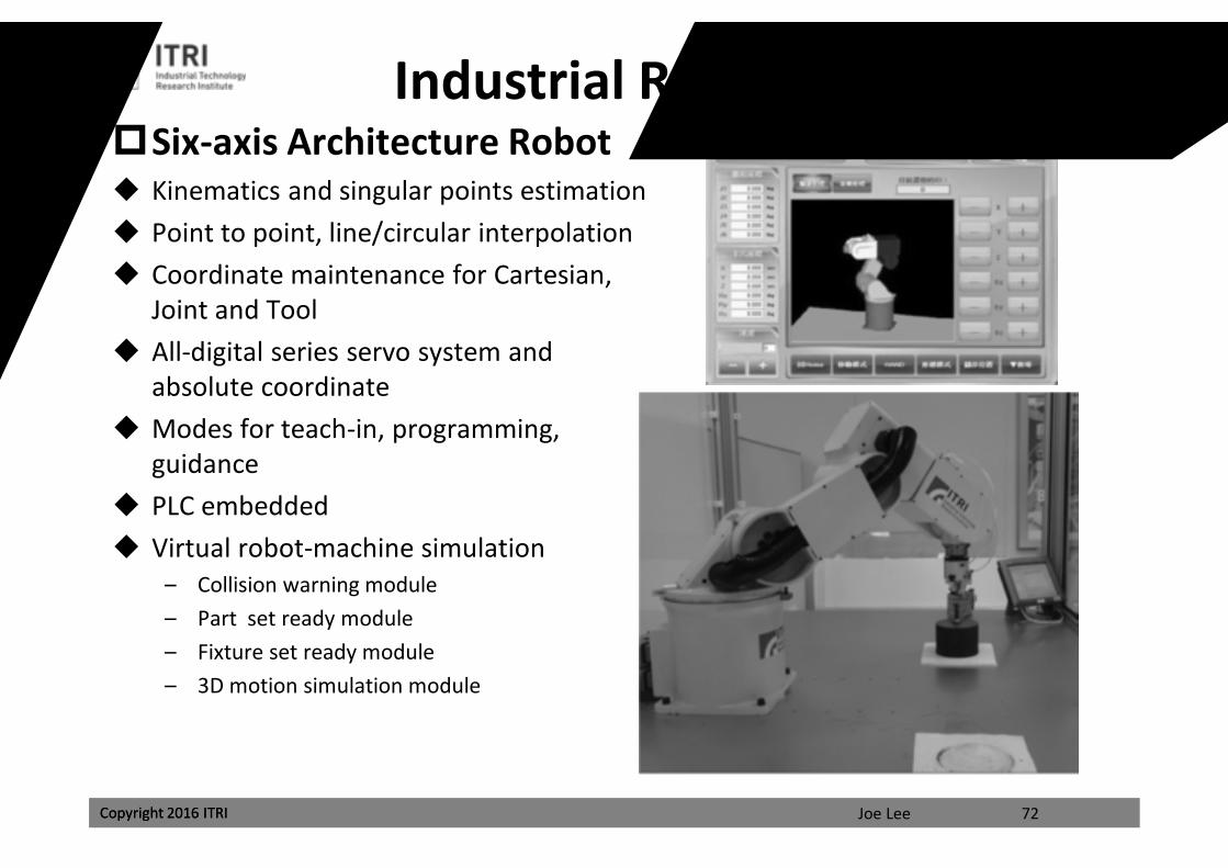
Industrial ROBOT ControlSix-axis Architecture Robot Kinematics and singular points estimation Point to point, line/circular interpolation Coordinate maintenance for Cartesian,
Joint and Tool All-digital series servo system and
absolute coordinate Modes for teach-in, programming,
guidance PLC embedded Virtual robot-machine simulation
– Collision warning module– Part set ready module– Fixture set ready module– 3D motion simulation module
72
課程講義
禁止轉載
Joe LeeCopyright 2016 ITRI Copyright 2016 ITRI
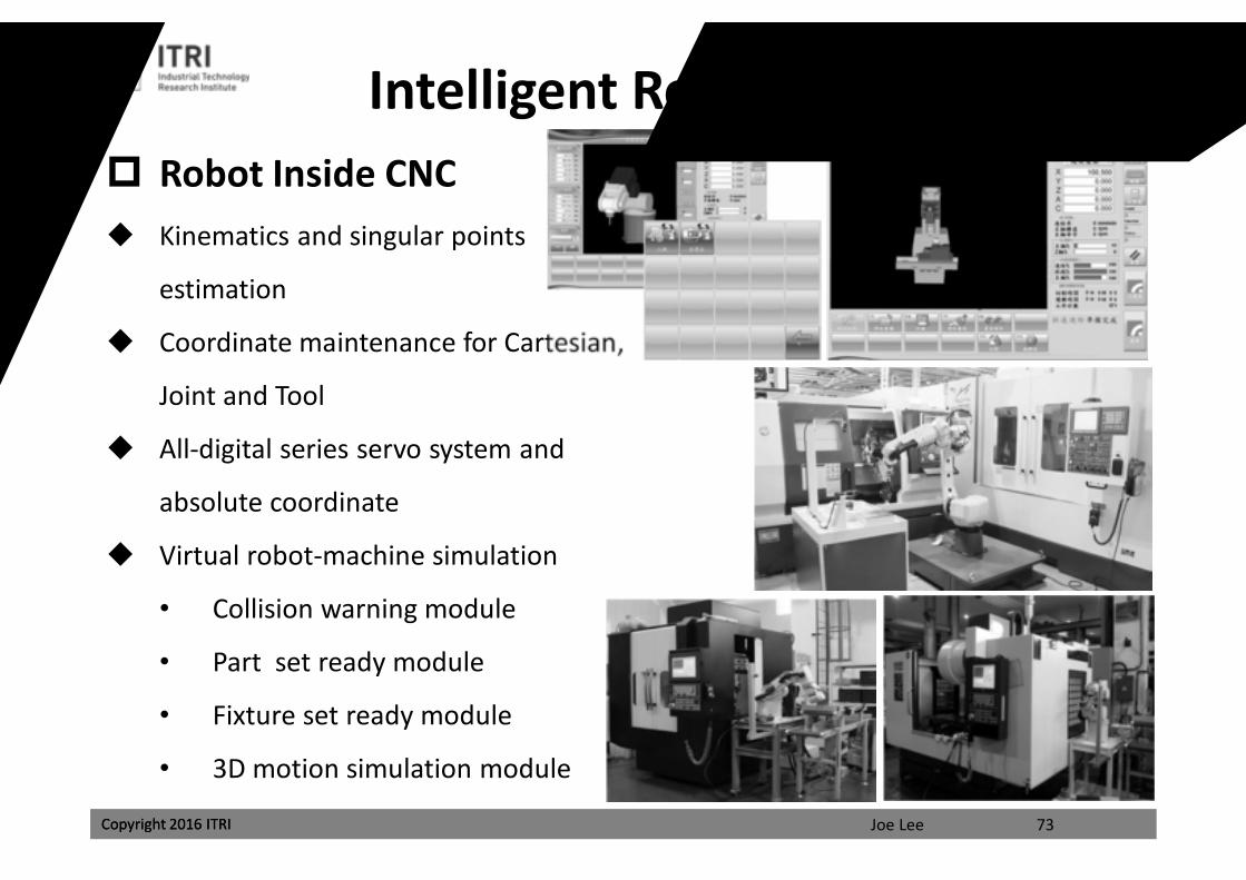
Robot Inside CNC Kinematics and singular points
estimation
Coordinate maintenance for Cartesian,
Joint and Tool
All-digital series servo system and
absolute coordinate
Virtual robot-machine simulation
• Collision warning module
• Part set ready module
• Fixture set ready module
• 3D motion simulation module
73
Intelligent Robotization Control
課程講義
禁止轉載
Joe LeeCopyright 2016 ITRI
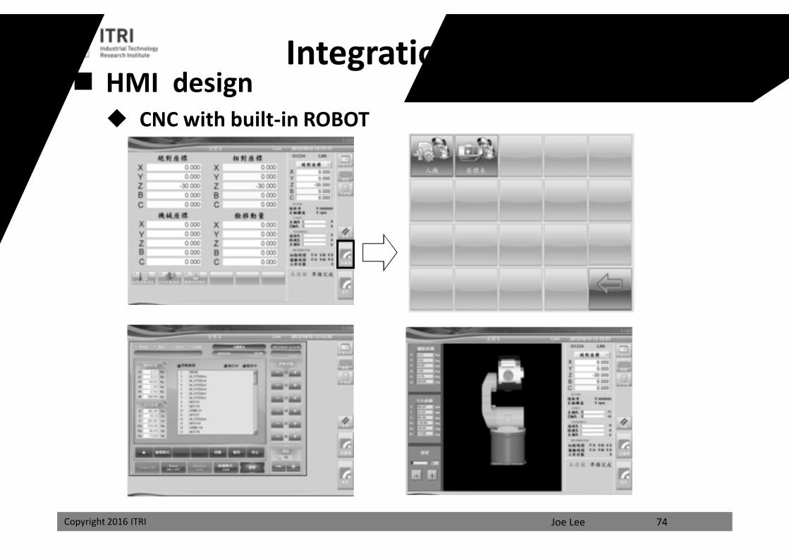
HMI design CNC with built-in ROBOT
74
Integration of Robots
課程講義
禁止轉載
Joe LeeCopyright 2016 ITRI Copyright 2016 ITRI
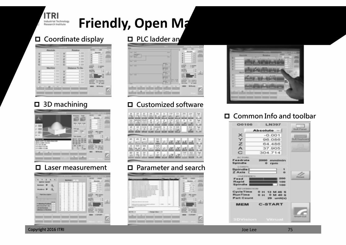
Friendly, Open Man-machine Interface Coordinate display
3D machining simulation
Intuitive touchscreen PLC ladder and IO status
Customized software panel
Parameter and search Laser measurement
Common Info and toolbar
75
課程講義
禁止轉載
Copyright 2016 ITRI Joe Lee
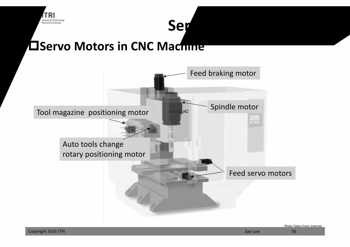
Spindle motor
Feed braking motor
Feed servo motors
Tool magazine positioning motor
Auto tools change rotary positioning motor
Servo DriveServo Motors in CNC Machine
Photo Taken From: Internet
76
課程講義
禁止轉載
Joe LeeCopyright 2016 ITRI
Servo Drive
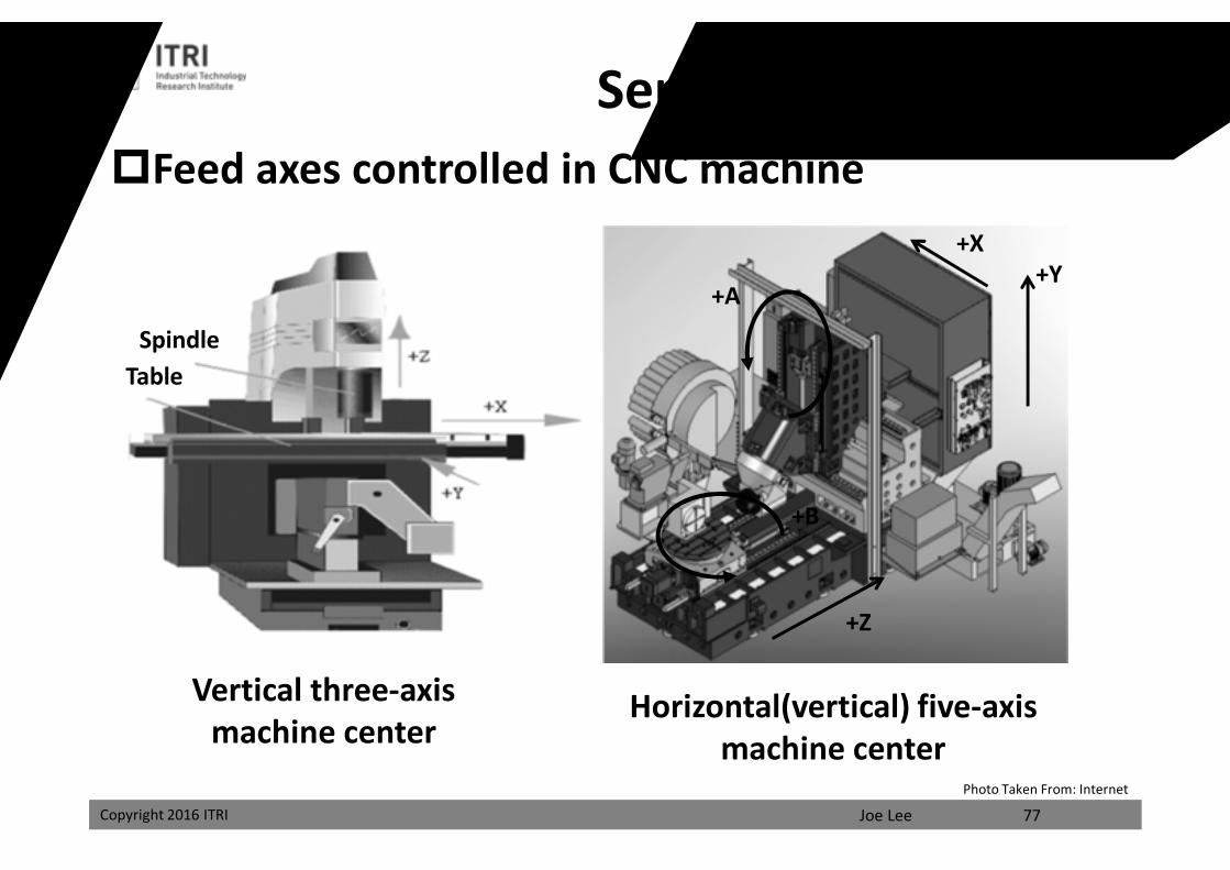
Vertical three-axis machine center
SpindleTable
Horizontal(vertical) five-axis machine center
+Y
+Z
+X
+B
+A
Feed axes controlled in CNC machine
Photo Taken From: Internet
77
課程講義
禁止轉載
Joe LeeCopyright 2016 ITRI
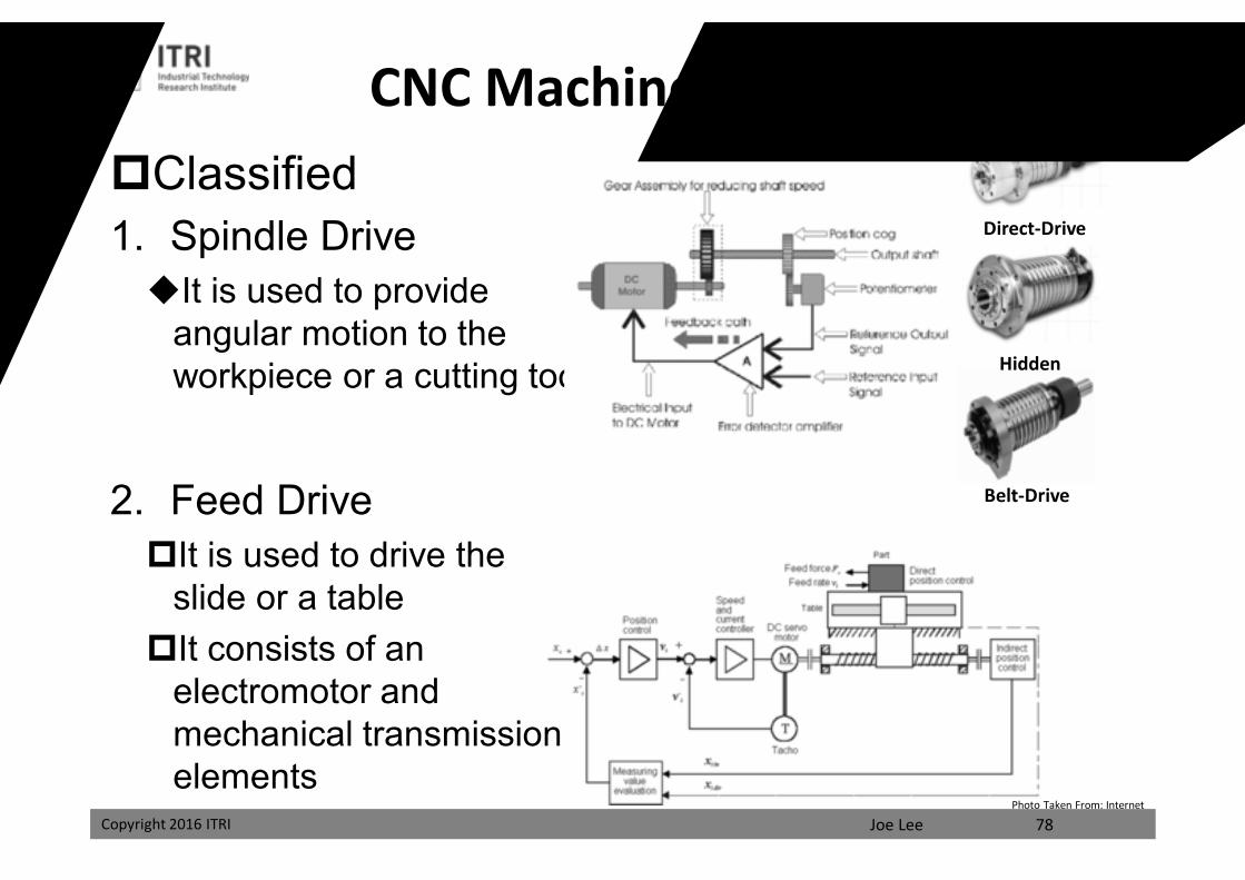
Classified1. Spindle DriveIt is used to provide
angular motion to the workpiece or a cutting tool
2. Feed DriveIt is used to drive the
slide or a tableIt consists of an
electromotor and mechanical transmission elements
CNC Machine Driving System
Direct-Drive
Hidden
Belt-Drive
Photo Taken From: Internet
78
課程講義
禁止轉載
Joe LeeCopyright 2016 ITRI
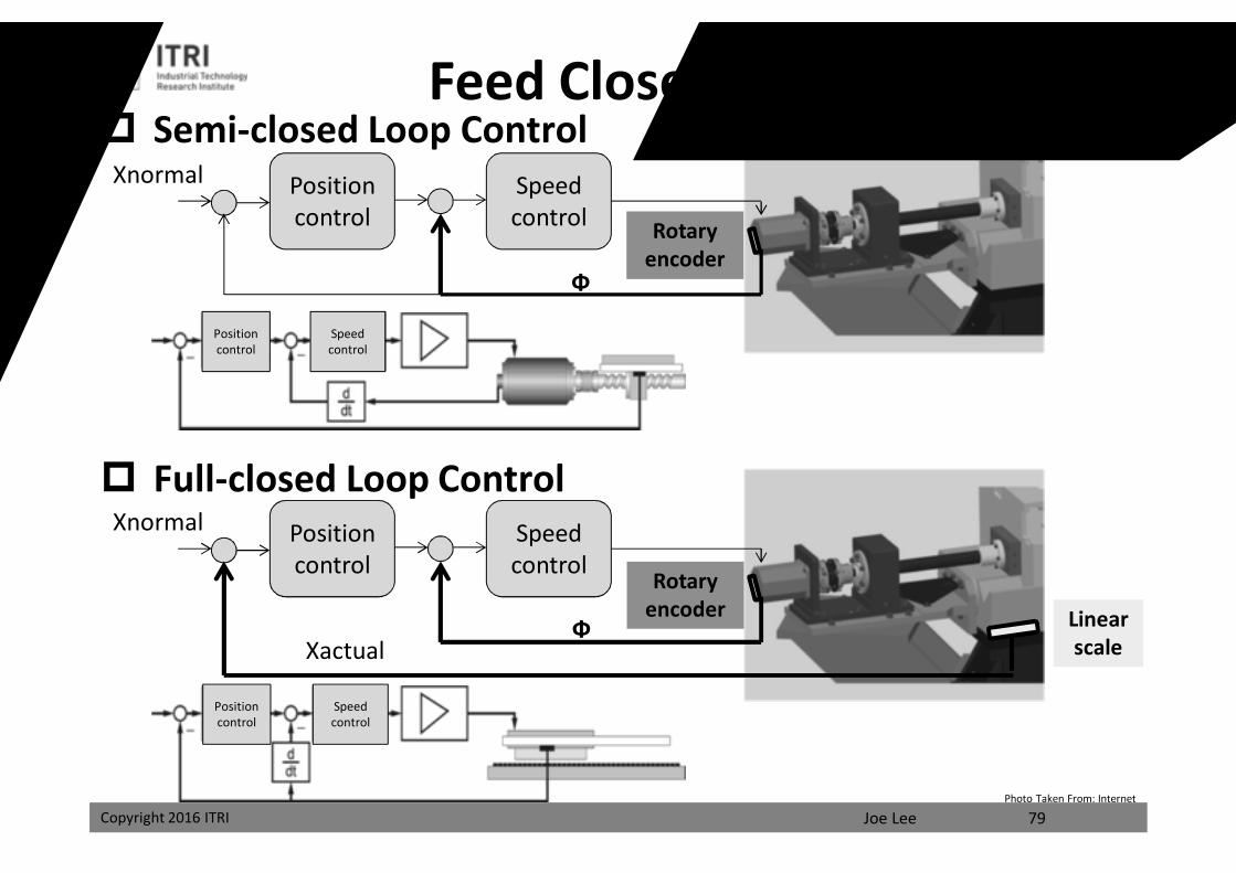
Feed Closed Loop Control Semi-closed Loop Control
Position control
Speed control
Xnormal
Full-closed Loop ControlPosition control
Speed control
Xnormal
Linear scale
Rotary encoder
Rotary encoder
Xactual
Ф
Ф
Position control
Position control
Speedcontrol
Speedcontrol
Photo Taken From: Internet
79
課程講義
禁止轉載
Joe LeeCopyright 2016 ITRI
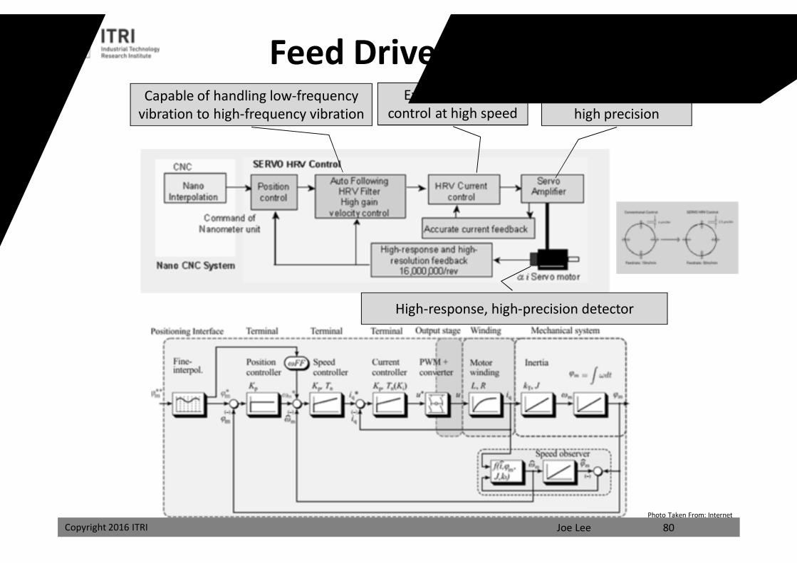
Feed Drive Servo SystemCapable of handling low-frequency
vibration to high-frequency vibrationExercise current
control at high speedDetect current with
high precision
High-response, high-precision detector
Photo Taken From: Internet
80
課程講義
禁止轉載
Joe LeeCopyright 2016 ITRI
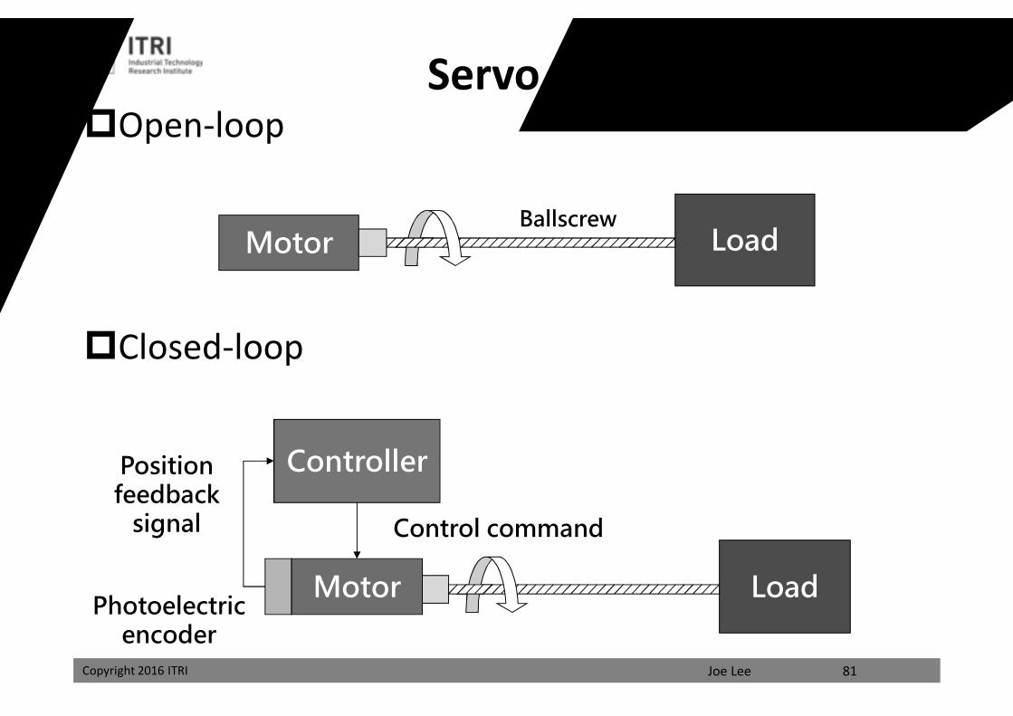
Servo PositioningOpen-loop
Closed-loop
LoadMotorBallscrew
LoadMotor
Controller
Control command
Position feedback
signal
Photoelectric encoder
81
課程講義
禁止轉載
Copyright 2016 ITRI Joe Lee
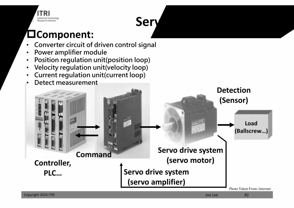
Servo System
82
Load(Ballscrew…)
Servo drive system(servo motor)
Servo drive system(servo amplifier)
CommandController,
PLC…
Detection(Sensor)
Component:• Converter circuit of driven control signal• Power amplifier module• Position regulation unit(position loop)• Velocity regulation unit(velocity loop)• Current regulation unit(current loop)• Detect measurement
Photo Taken From: Internet
課程講義
禁止轉載
Joe LeeCopyright 2016 ITRI
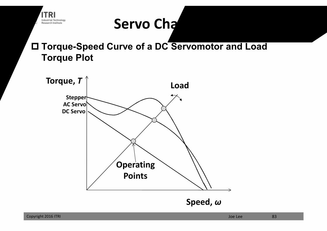
Torque-Speed Curve of a DC Servomotor and Load Torque Plot
Torque, T
Speed, ω
Load
OperatingPoints
DC ServoAC Servo
Stepper
Servo Characteristic Data
83
課程講義
禁止轉載
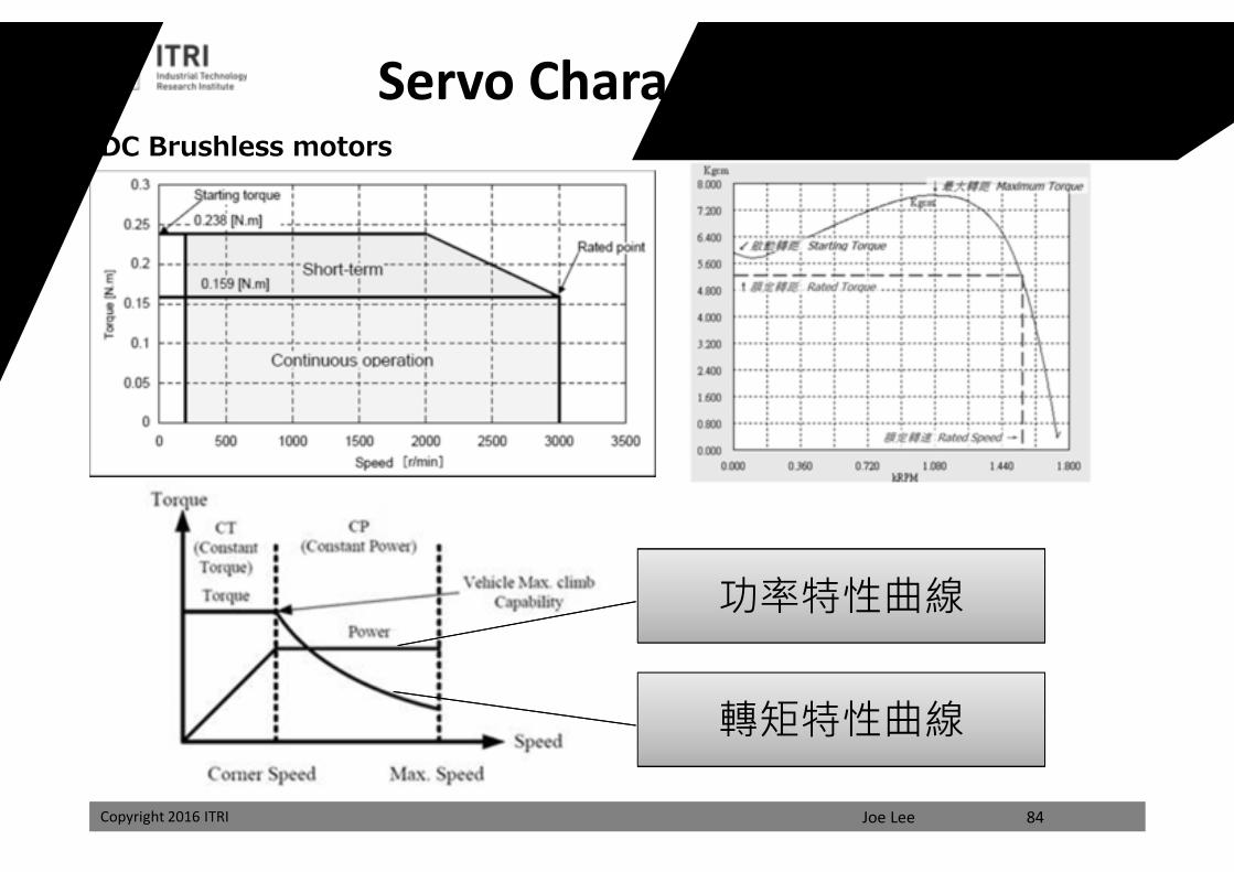
Joe LeeCopyright 2016 ITRI 84
DC Brushless motors
轉矩特性曲線
功率特性曲線
Servo Characteristic Diagram
課程講義
禁止轉載
Copyright 2016 ITRI Joe Lee
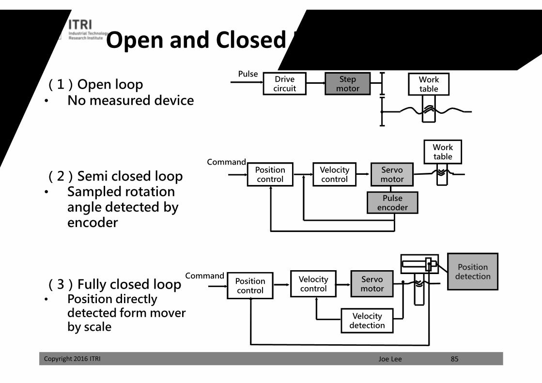
Open and Closed Loop Servo SystemDrive circuit
Step motor
Work table
Pulse
(1)Open loop• No measured device
(2)Semi closed loop• Sampled rotation
angle detected by encoder
(3)Fully closed loop• Position directly
detected form mover by scale
Servo motor
Velocity control
Position control
Work table
Pulse encoder
Command
Servo motor
Velocity detection
Velocity control
Position control
Position detection
85
Command
課程講義
禁止轉載
Joe LeeCopyright 2016 ITRI
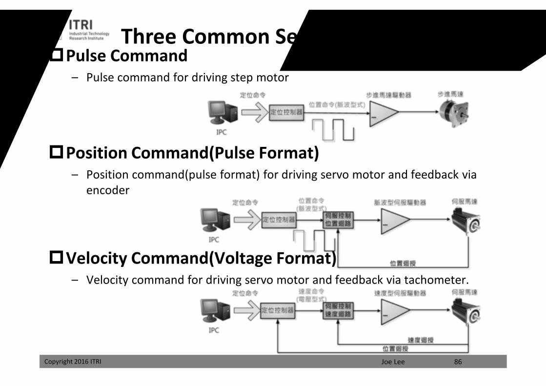
Pulse Command– Pulse command for driving step motor
Position Command(Pulse Format)– Position command(pulse format) for driving servo motor and feedback via
encoder
Velocity Command(Voltage Format)– Velocity command for driving servo motor and feedback via tachometer.
Three Common Servo Control Modes
86
課程講義
禁止轉載
Joe LeeCopyright 2016 ITRI
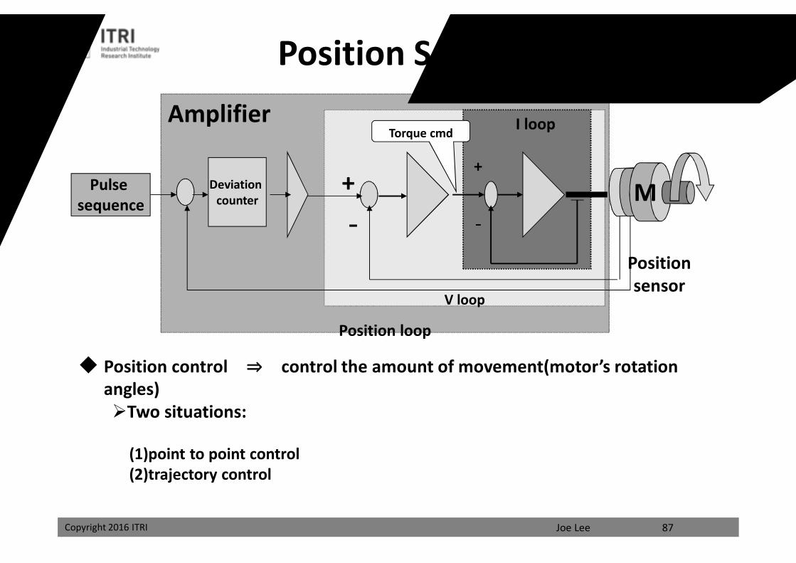
Position Servo Control
87
Amplifier
Position loop
V loop
I loop
+
-
Pulse sequence
+
-
Torque cmd
Deviation counter
Position sensor
Position control ⇒ control the amount of movement(motor’s rotation angles)Two situations:
(1)point to point control(2)trajectory control
課程講義
禁止轉載
Joe LeeCopyright 2016 ITRI
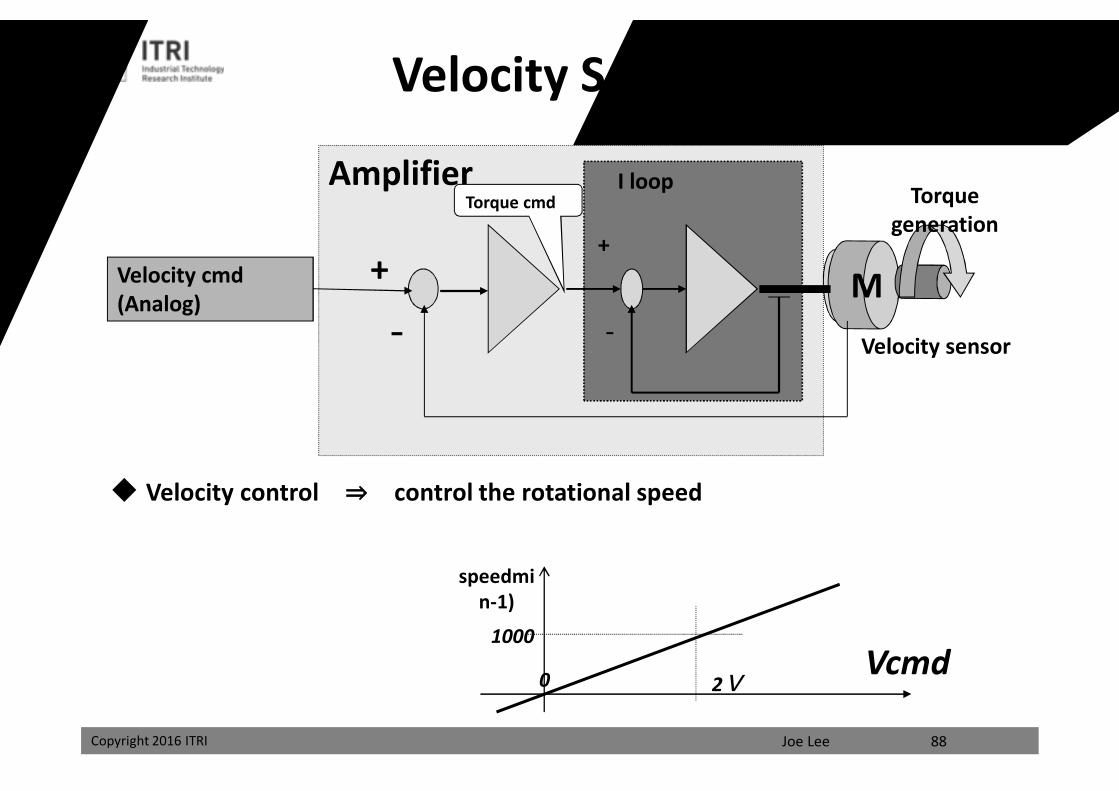
Velocity Servo Control
88
Velocity control ⇒ control the rotational speed
Amplifier I loop
+
-
Velocity cmd(Analog)
+
-
Torque cmd Torque generation
Velocity sensor
Vcmd1000
speedmin-1)
2V0
課程講義
禁止轉載
Joe LeeCopyright 2016 ITRI
Torque Servo Control
89
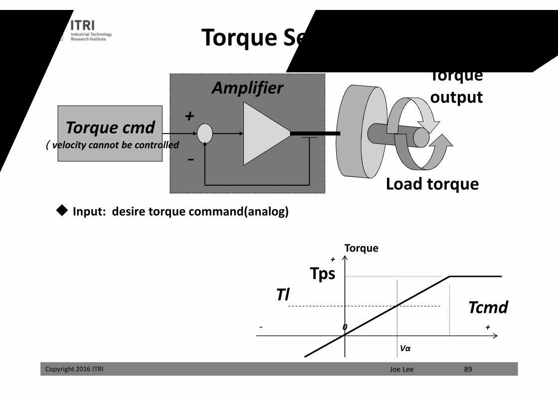
Input: desire torque command(analog)
AmplifierTorque output
Torque cmd(velocity cannot be controlled
+
-Load torque
TcmdTl
Torque
Vα
0 +-
+
Tps
課程講義
禁止轉載
Joe LeeCopyright 2016 ITRI
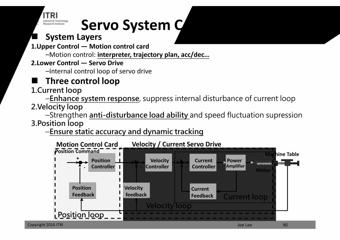
System Layers1.Upper Control — Motion control card
–Motion control: interpreter, trajectory plan, acc/dec…2.Lower Control — Servo Drive
–Internal control loop of servo drive Three control loop1.Current loop
–Enhance system response, suppress internal disturbance of current loop2.Velocity loop
–Strengthen anti-disturbance load ability and speed fluctuation supression3.Position loop
–Ensure static accuracy and dynamic tracking
PositionController
VelocityController
Velocity feedback
Position Feedback
Position Command
servomotor++
- -
Machine TableCurrent
Controller+
-PowerAmplifier
Current Feedback
Velocity / Current Servo DriveMotion Control Card
Motor
Servo System Control Architecture
Current loopVelocity loop
Position loop90
課程講義
禁止轉載
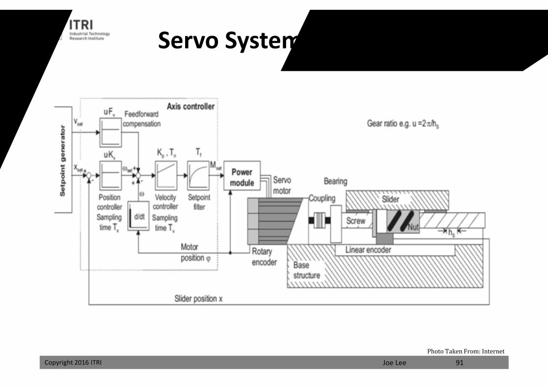
Joe LeeCopyright 2016 ITRI 91
Servo System Feedback Control
Photo Taken From: Internet
課程講義
禁止轉載
Joe LeeCopyright 2016 ITRI
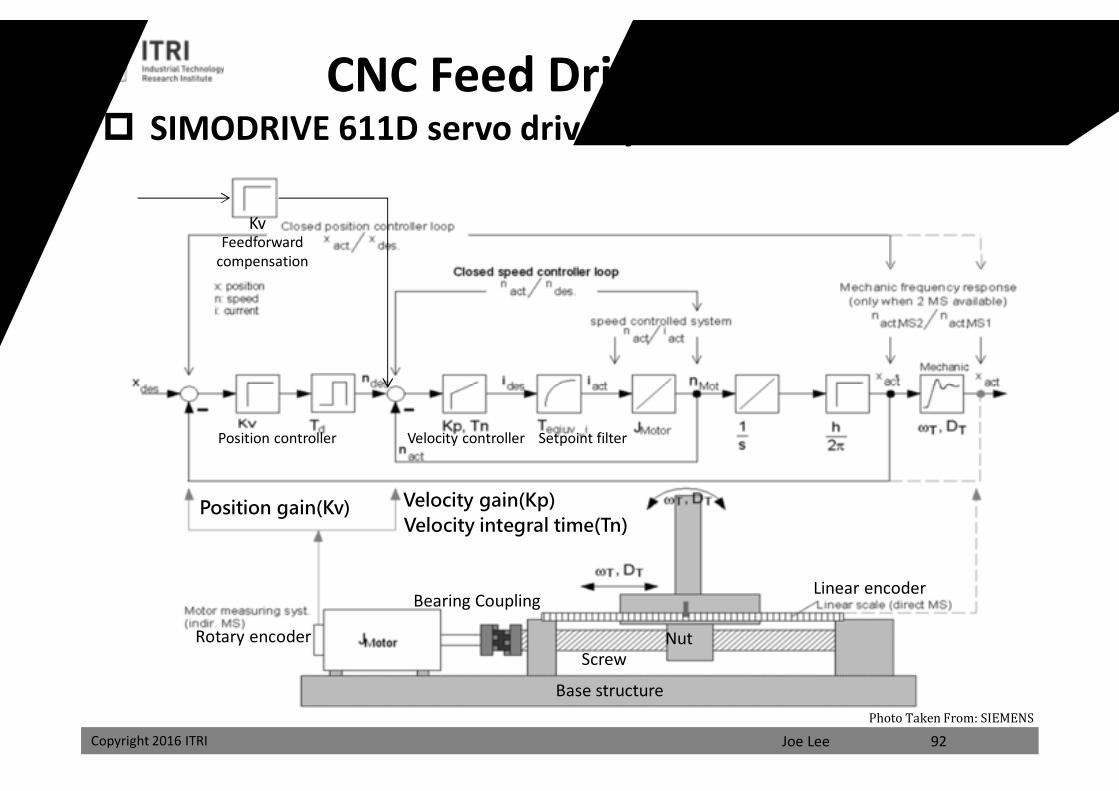
SIMODRIVE 611D servo drive system
92
Velocity gain(Kp)Velocity integral time(Tn)
Position gain(Kv)
Base structure
Coupling
Rotary encoder
Linear encoderBearing
ScrewNut
KvFeedforward
compensation
Position controller Velocity controller Setpoint filter
CNC Feed Drive Servo System
Photo Taken From: SIEMENS
課程講義
禁止轉載
Joe LeeCopyright 2016 ITRI
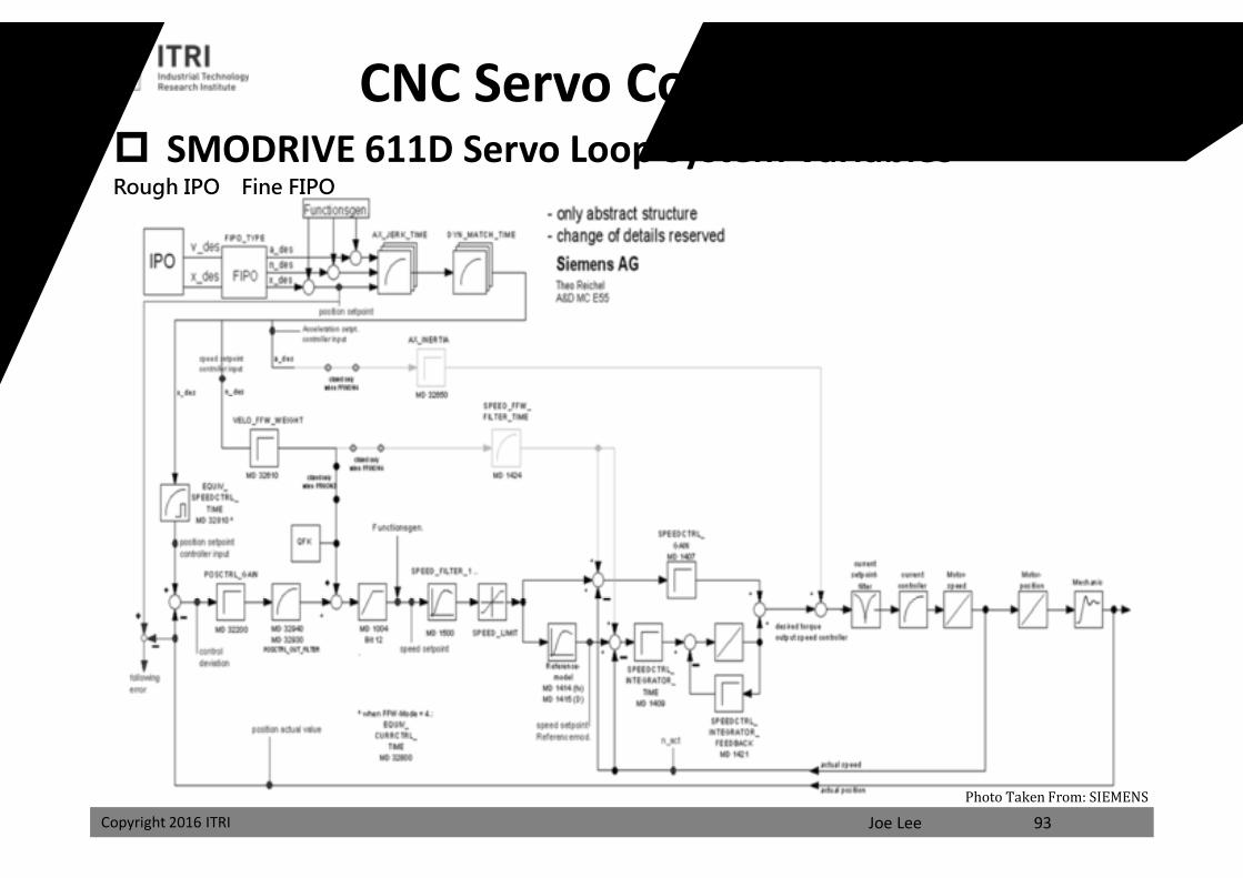
SMODRIVE 611D Servo Loop System VariablesCNC Servo Control Architecture
93
Rough IPO Fine FIPO
Photo Taken From: SIEMENS
課程講義
禁止轉載
Joe LeeCopyright 2016 ITRI
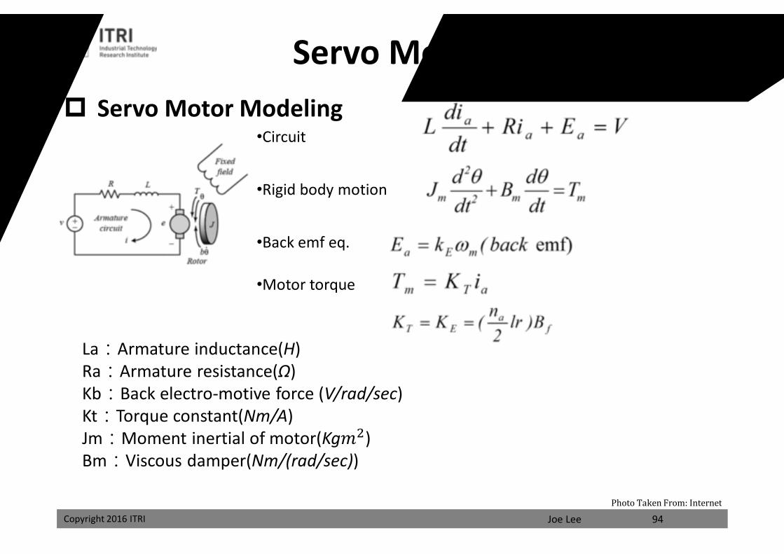
Servo Motor Modeling
Servo Motor Modeling
94
La:Armature inductance(H)Ra:Armature resistance(Ω)Kb:Back electro-motive force (V/rad/sec)Kt:Torque constant(Nm/A)Jm:Moment inertial of motor(Kg푚 )Bm:Viscous damper(Nm/(rad/sec))
•Circuit
•Back emf eq.
•Motor torque
•Rigid body motion
Photo Taken From: Internet
課程講義
禁止轉載
Joe LeeCopyright 2016 ITRI 95
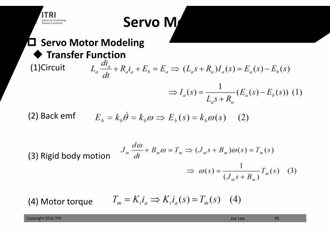
Transfer Function(1)Circuit
(2) Back emf
(3) Rigid body motion
(4) Motor torque
Servo Motor Modeling Servo Motor Modeling
課程講義
禁止轉載
Joe LeeCopyright 2016 ITRI 96
Kb
Kt
+
-
Ea(s) Ia(s) Tm(s)
Eb(s)
Kb
+
-
Ea(s)
Eb(s)
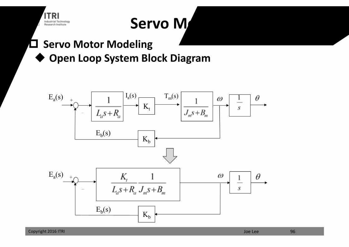
Servo Motor Modeling Open Loop System Block Diagram
Servo Motor Modeling
課程講義
禁止轉載
Joe LeeCopyright 2016 ITRI 97
Kb
Kt+ +
-
-Ea(s) Ia(s) Tm(s)
TL(s)
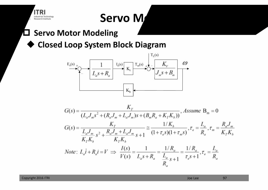
Servo Motor Modeling Closed Loop System Block Diagram
Servo Motor Modeling
課程講義
禁止轉載
Joe LeeCopyright 2016 ITRI
Pout(s)+
98
Kpp
Kb
K2
Kt
Kv
Ks
+ + + +- -
-
-
-Pin(s) Vin(s)
Icom(s) Ect(s) Ea(s) Ia(s) Tm(s)TL(s)
Ωm(s) Ξm(s)
sKK I
P+
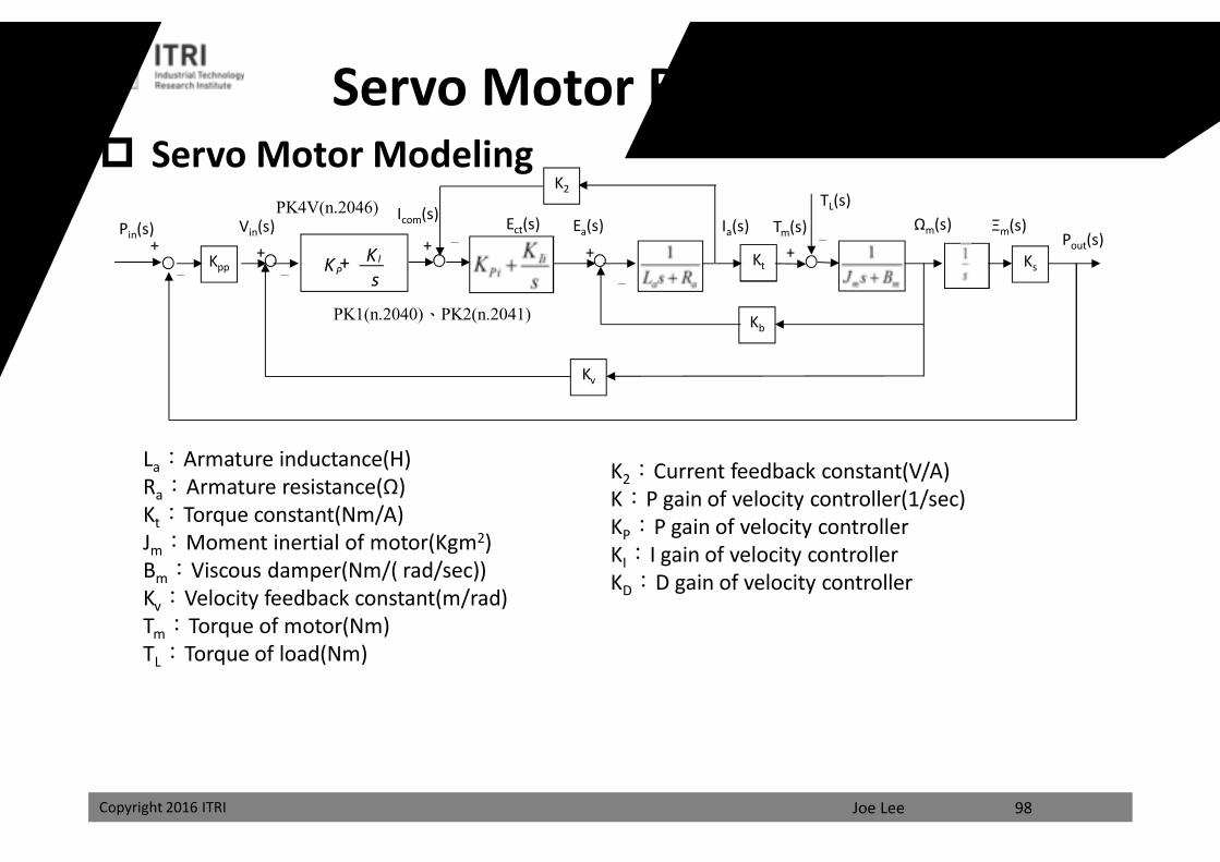
La:Armature inductance(H)Ra:Armature resistance(Ω)Kt:Torque constant(Nm/A)Jm:Moment inertial of motor(Kgm2)Bm:Viscous damper(Nm/( rad/sec))Kv:Velocity feedback constant(m/rad)Tm:Torque of motor(Nm)TL:Torque of load(Nm)
K2:Current feedback constant(V/A)K:P gain of velocity controller(1/sec)KP:P gain of velocity controllerKI:I gain of velocity controllerKD:D gain of velocity controller
Servo Motor Block Diagram
PK1(n.2040)、PK2(n.2041)
PK4V(n.2046)
Servo Motor Modeling
課程講義
禁止轉載
Joe LeeCopyright 2016 ITRI
Ea(s)
99
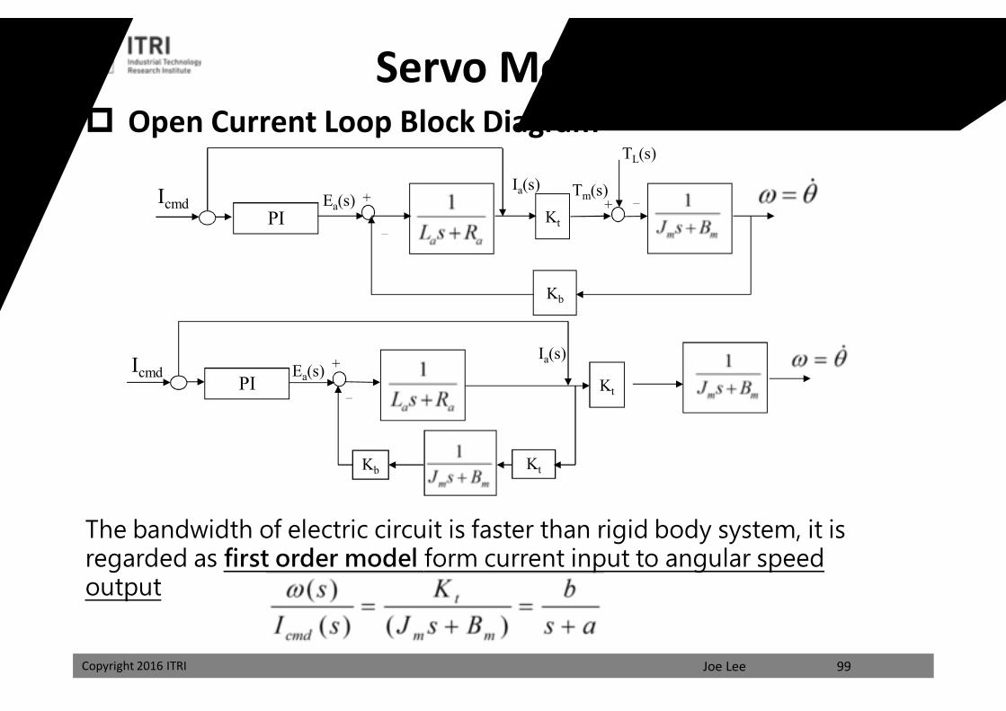
The bandwidth of electric circuit is faster than rigid body system, it is regarded as first order model form current input to angular speed output
Ea(s)
Kb
Kt
+ +
-
-
Ia(s) Tm(s)
TL(s)
PIIcmd
Kb
Kt
+
-
Ia(s)
PI
Kt
Icmd
Servo Motor Modeling Open Current Loop Block Diagram
課程講義
禁止轉載
Joe LeeCopyright 2016 ITRI 100
Servo system dynamicVelocity controllerPosition controller
-
r (s)
-
Velocity feedforword controller
+ +y (s)
v Tcom
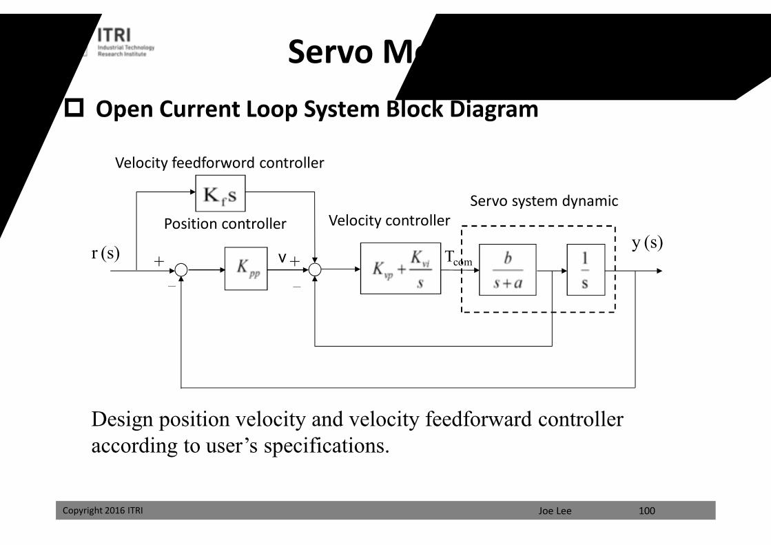
Servo Motor Modeling Open Current Loop System Block Diagram
Design position velocity and velocity feedforward controller according to user’s specifications.
課程講義
禁止轉載
Joe LeeCopyright 2016 ITRI 101
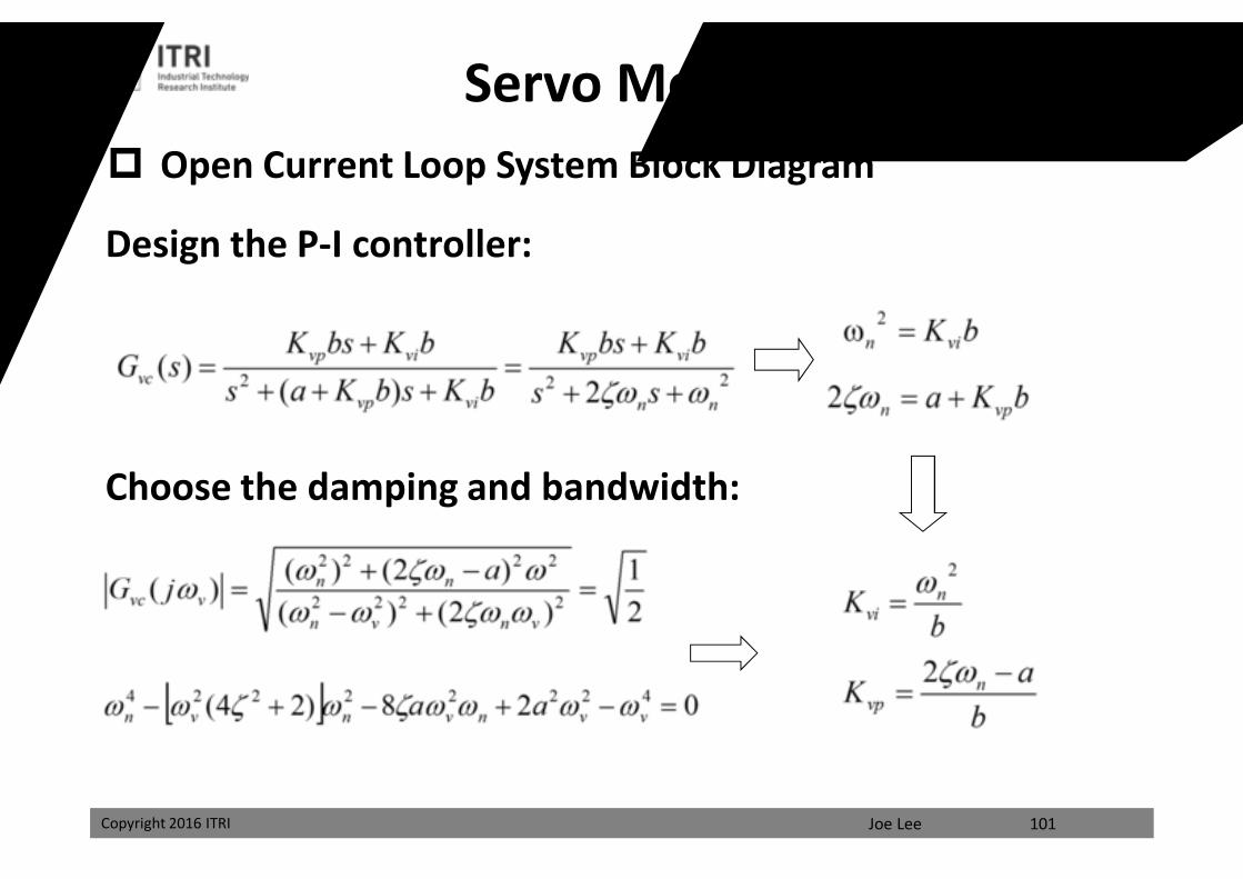
Servo Motor Modeling Open Current Loop System Block Diagram
Design the P-I controller:
Choose the damping and bandwidth:
課程講義
禁止轉載
Joe LeeCopyright 2016 ITRI 102
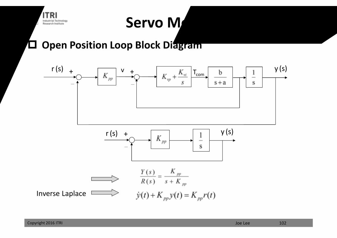
Servo Motor Modeling Open Position Loop Block Diagram
-
r (s)
-
+ + y (s)v Tcom
r (s)
-
+ y (s)
Inverse Laplace
課程講義
禁止轉載
Joe LeeCopyright 2016 ITRI Copyright 2016 ITRI
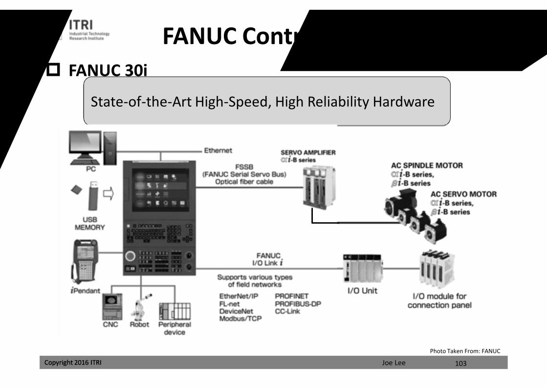
FANUC Controller Architecture
State-of-the-Art High-Speed, High Reliability Hardware
FANUC 30i
103
Photo Taken From: FANUC
課程講義
禁止轉載
Joe LeeCopyright 2016 ITRI Copyright 2016 ITRI
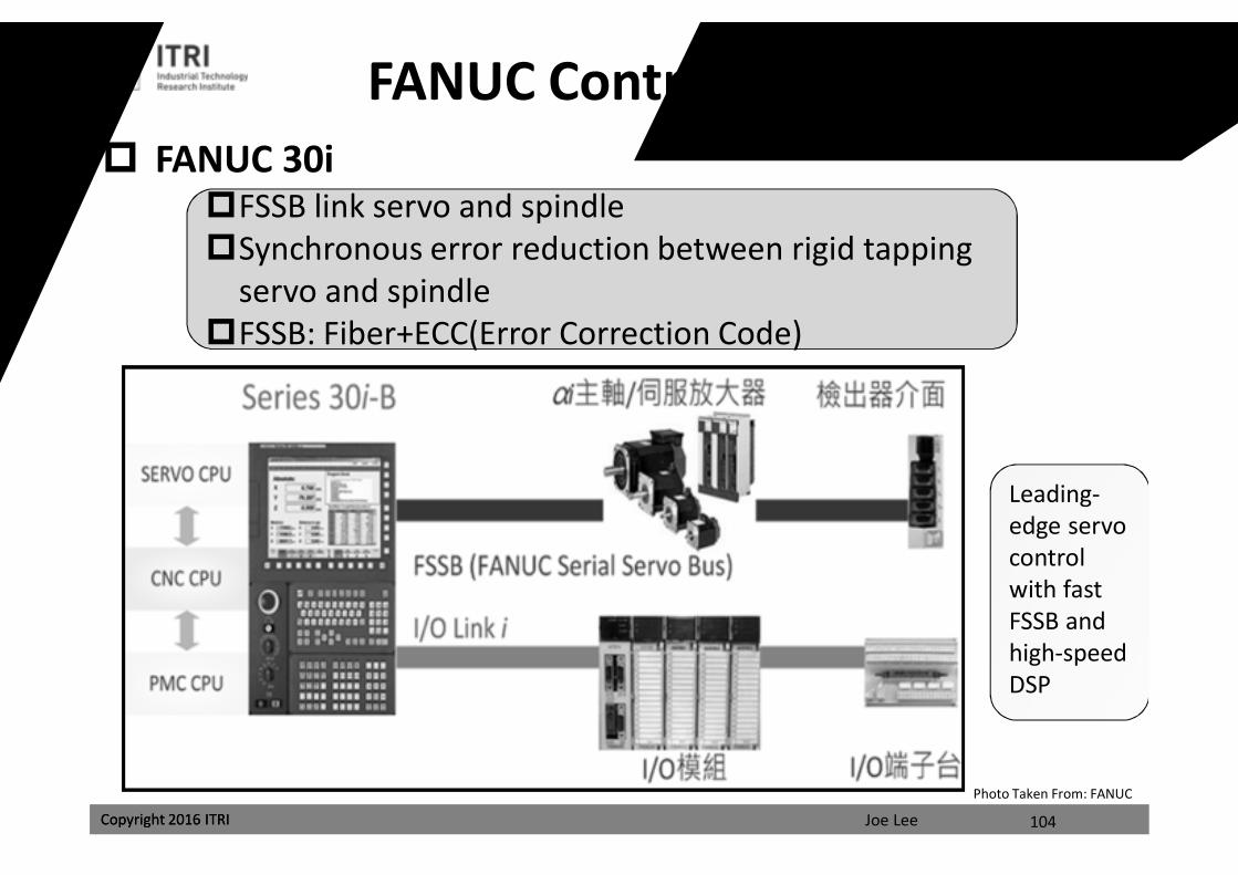
FANUC Controller Architecture
FSSB link servo and spindleSynchronous error reduction between rigid tapping
servo and spindleFSSB: Fiber+ECC(Error Correction Code)
FANUC 30i
104
Photo Taken From: FANUC
Leading-edge servo controlwith fast FSSB and high-speed DSP
課程講義
禁止轉載
Joe LeeCopyright 2016 ITRI
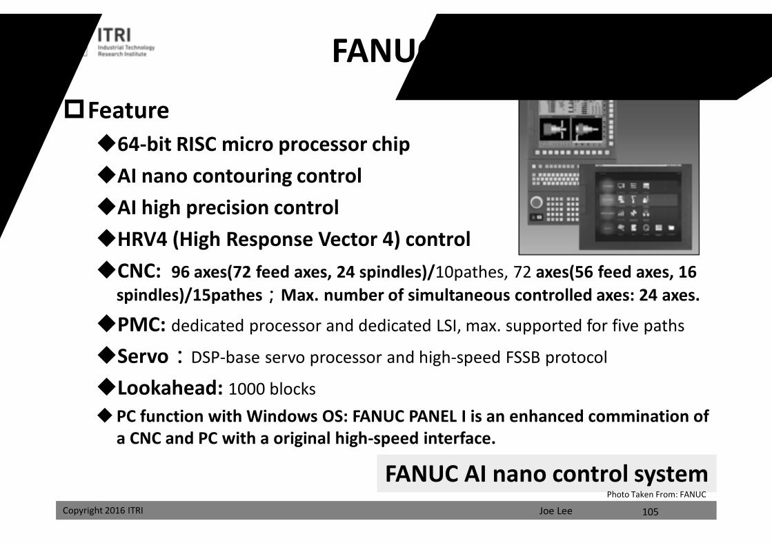
Feature64-bit RISC micro processor chipAI nano contouring controlAI high precision controlHRV4 (High Response Vector 4) controlCNC: 96 axes(72 feed axes, 24 spindles)/10pathes, 72 axes(56 feed axes, 16
spindles)/15pathes;Max. number of simultaneous controlled axes: 24 axes.
PMC: dedicated processor and dedicated LSI, max. supported for five paths
Servo:DSP-base servo processor and high-speed FSSB protocol
Lookahead: 1000 blocksPC function with Windows OS: FANUC PANEL I is an enhanced commination of
a CNC and PC with a original high-speed interface.
FANUC AI nano control system
FANUC 30i Series
105
Photo Taken From: FANUC
課程講義
禁止轉載
Joe LeeCopyright 2016 ITRI Copyright 2016 ITRI
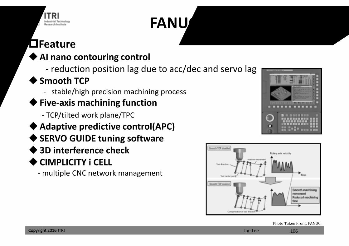
FANUC 30i SeriesFeatureAI nano contouring control
- reduction position lag due to acc/dec and servo lag Smooth TCP
- stable/high precision machining process Five-axis machining function
- TCP/tilted work plane/TPCAdaptive predictive control(APC) SERVO GUIDE tuning software3D interference check CIMPLICITY i CELL
- multiple CNC network management
106
Photo Taken From: FANUC
課程講義
禁止轉載
Joe LeeCopyright 2016 ITRI
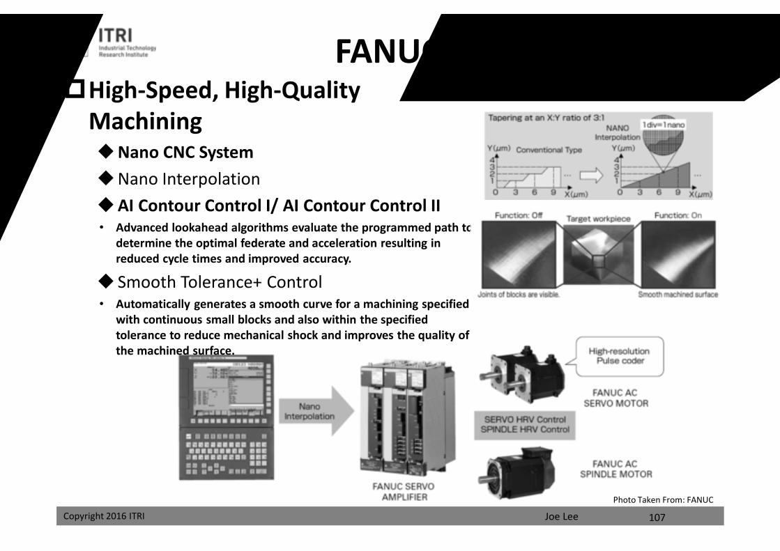
FANUC 30i SeriesHigh-Speed, High-Quality
MachiningNano CNC SystemNano InterpolationAI Contour Control I/ AI Contour Control II• Advanced lookahead algorithms evaluate the programmed path to
determine the optimal federate and acceleration resulting in reduced cycle times and improved accuracy.
Smooth Tolerance+ Control• Automatically generates a smooth curve for a machining specified
with continuous small blocks and also within the specified tolerance to reduce mechanical shock and improves the quality of the machined surface.
107
Photo Taken From: FANUC
課程講義
禁止轉載
Joe LeeCopyright 2016 ITRI
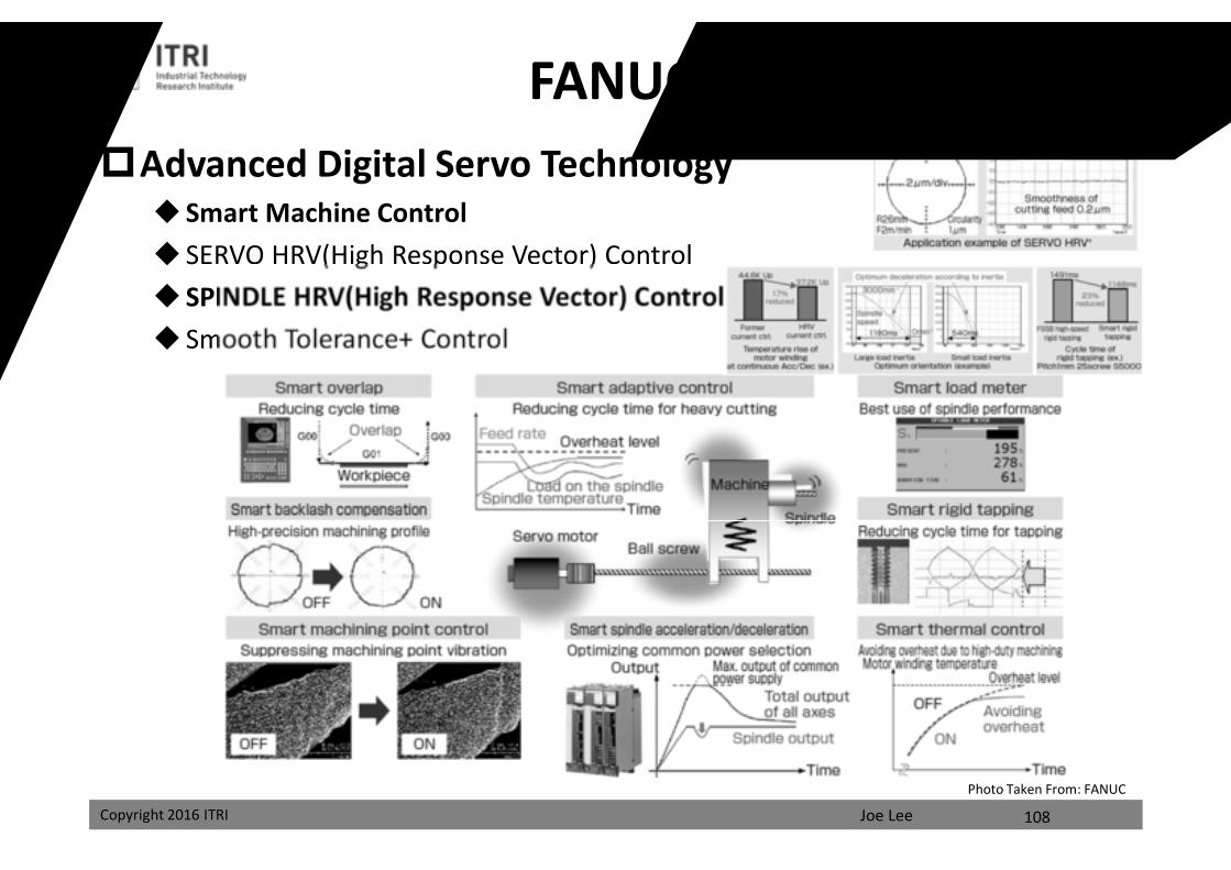
FANUC 30i SeriesAdvanced Digital Servo Technology
Smart Machine Control SERVO HRV(High Response Vector) Control SPINDLE HRV(High Response Vector) Control Smooth Tolerance+ Control
108
Photo Taken From: FANUC
課程講義
禁止轉載
Joe LeeCopyright 2016 ITRI
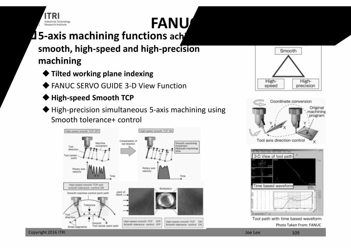
FANUC 30i Series5-axis machining functions achieves a
smooth, high-speed and high-precision machiningTilted working plane indexing FANUC SERVO GUIDE 3-D View FunctionHigh-speed Smooth TCPHigh-precision simultaneous 5-axis machining using
Smooth tolerance+ control
109
Photo Taken From: FANUC
課程講義
禁止轉載
Joe LeeCopyright 2016 ITRI
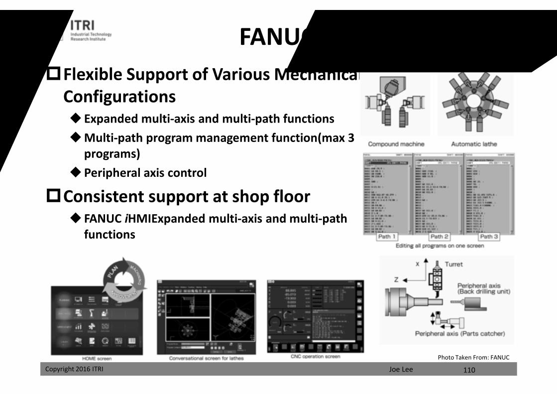
FANUC 30i SeriesFlexible Support of Various Mechanical
Configurations Expanded multi-axis and multi-path functionsMulti-path program management function(max 3
programs)Peripheral axis control
Consistent support at shop floor FANUC iHMIExpanded multi-axis and multi-path
functions
110
Photo Taken From: FANUC
課程講義
禁止轉載
Joe LeeCopyright 2016 ITRI
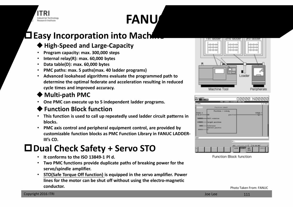
FANUC 30i SeriesEasy Incorporation into Machine
High-Speed and Large-Capacity• Program capacity: max. 300,000 steps• Internal relay(R): max. 60,000 bytes• Data table(D): max. 60,000 bytes• PMC paths: max. 5 paths(max. 40 ladder programs)• Advanced lookahead algorithms evaluate the programmed path to
determine the optimal federate and acceleration resulting in reduced cycle times and improved accuracy.
Multi-path PMC• One PMC can execute up to 5 independent ladder programs.
Function Block function• This function is used to call up repeatedly used ladder circuit patterns in
blocks.• PMC axis control and peripheral equipment control, are provided by
customizable function blocks as PMC Function Library in FANUC LADDER-III’s CD.
Dual Check Safety + Servo STO• It conforms to the ISO 13849-1 Pl d.• Two PMC functions provide duplicate paths of breaking power for the
servo/spindle amplifier.• STO(Safe Torque Off function) is equipped in the servo amplifier. Power
lines for the motor can be shut off without using the electro-magnetic conductor.
111
Photo Taken From: FANUC
課程講義
禁止轉載
Joe LeeCopyright 2016 ITRI
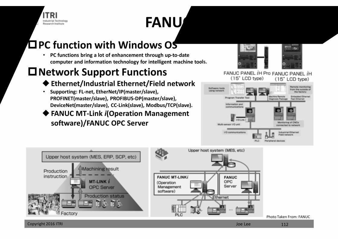
FANUC 30i SeriesPC function with Windows OS
• PC functions bring a lot of enhancement through up-to-date computer and information technology for intelligent machine tools.
Network Support Functions Ethernet/Industrial Ethernet/Field network• Supporting: FL-net, EtherNet/IP(master/slave),
PROFINET(master/slave), PROFIBUS-DP(master/slave), DeviceNet(master/slave), CC-Link(slave), Modbus/TCP(slave).
FANUC MT-Link i(Operation Management software)/FANUC OPC Server
112
Photo Taken From: FANUC
課程講義
禁止轉載
Joe LeeCopyright 2016 ITRI
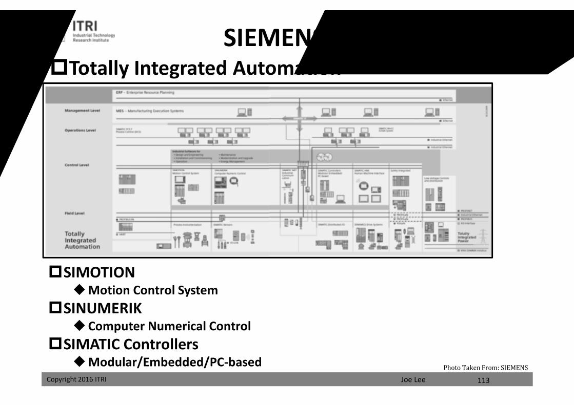
SIEMENS TIA
SIMOTIONMotion Control System
SINUMERIK Computer Numerical Control
SIMATIC ControllersModular/Embedded/PC-based
113
Photo Taken From: SIEMENS
Totally Integrated Automation
課程講義
禁止轉載
Joe LeeCopyright 2016 ITRI
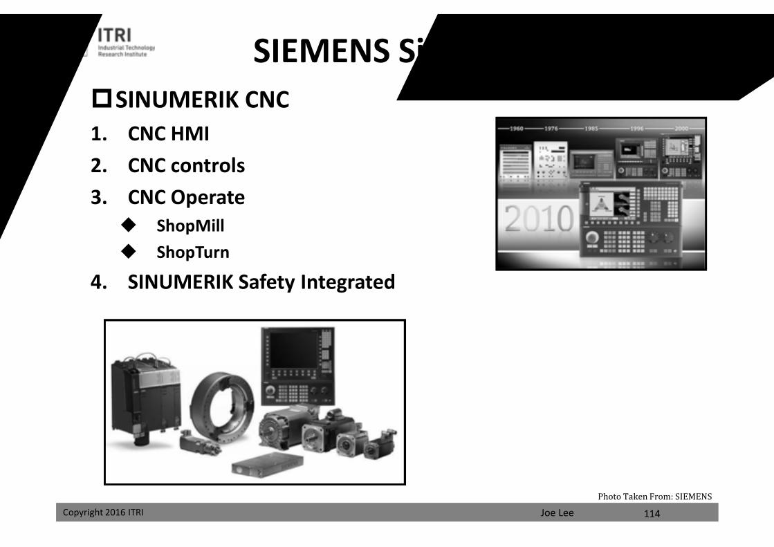
SIEMENS Sinumerik SystemSINUMERIK CNC 1. CNC HMI 2. CNC controls3. CNC Operate ShopMill ShopTurn
4. SINUMERIK Safety Integrated
114
Photo Taken From: SIEMENS
課程講義
禁止轉載
Joe LeeCopyright 2016 ITRI Copyright 2016 ITRI
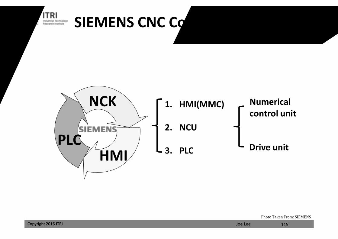
HMI
NCK
PLC
SIEMENS CNC Controls Architecture
1. HMI(MMC)
2. NCU
3. PLC
Numerical control unit
Drive unit
115
Photo Taken From: SIEMENS
課程講義
禁止轉載
Joe LeeCopyright 2016 ITRI Copyright 2016 ITRI
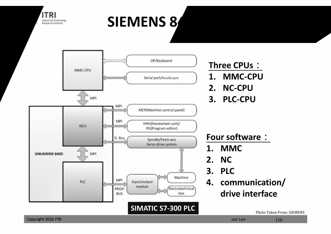
SIEMENS 840D Architecture
Three CPUs:1. MMC-CPU2. NC-CPU3. PLC-CPU
Four software:1. MMC2. NC3. PLC4. communication/
drive interfaceSIMATIC S7-300 PLC
116
Photo Taken From: SIEMENS
課程講義
禁止轉載
Joe LeeCopyright 2016 ITRI Copyright 2016 ITRI
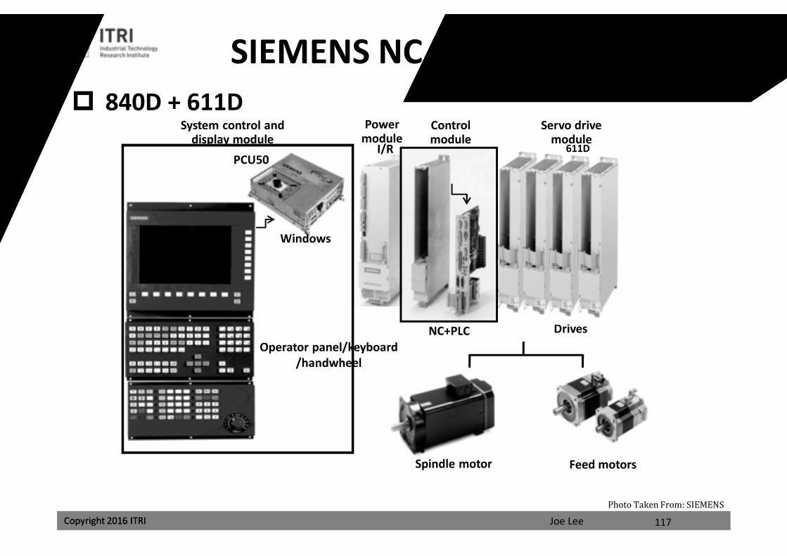
SIEMENS NC Control and Servo
Spindle motor
I/R
Operator panel/keyboard/handwheel
Windows
Feed motors
NC+PLC Drives
PCU50
Power module
Control module
System control and display module
Servo drive module
611D
840D + 611D
117
Photo Taken From: SIEMENS
課程講義
禁止轉載
Joe LeeCopyright 2016 ITRI Copyright 2016 ITRI
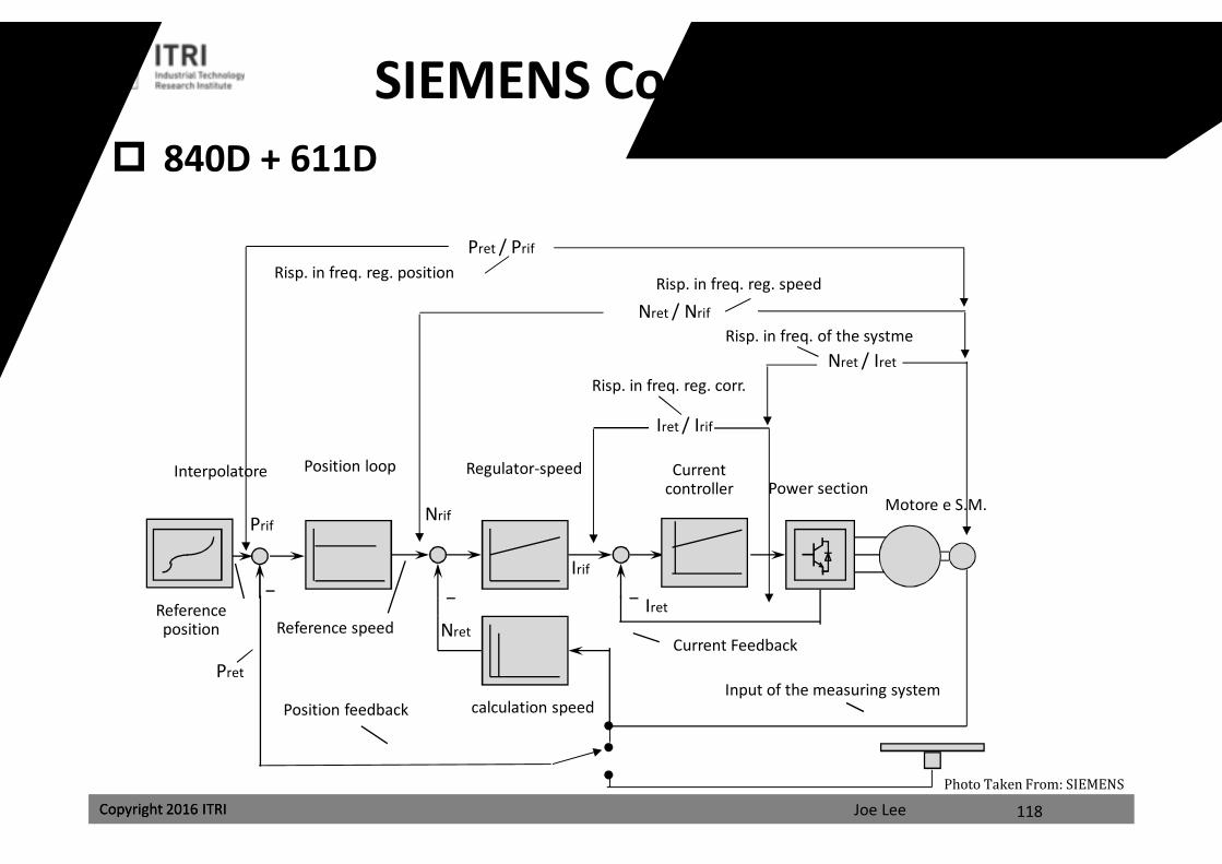
SIEMENS Controller Structure 840D + 611D
118
Photo Taken From: SIEMENS
Regulator-speedPosition loop
Reference position Reference speed
calculation speed
Current controller
InterpolatorePower section
Motore e S.M.
Input of the measuring systemPosition feedback
Current Feedback
Iret / Irif
Iret
Irif
Nret / Iret
Nret
Nret / Nrif
Risp. in freq. reg. speed
Risp. in freq. reg. corr.
Risp. in freq. of the systme
Pret / Prif
Risp. in freq. reg. position
Pret
NrifPrif
課程講義
禁止轉載
Joe LeeCopyright 2016 ITRI
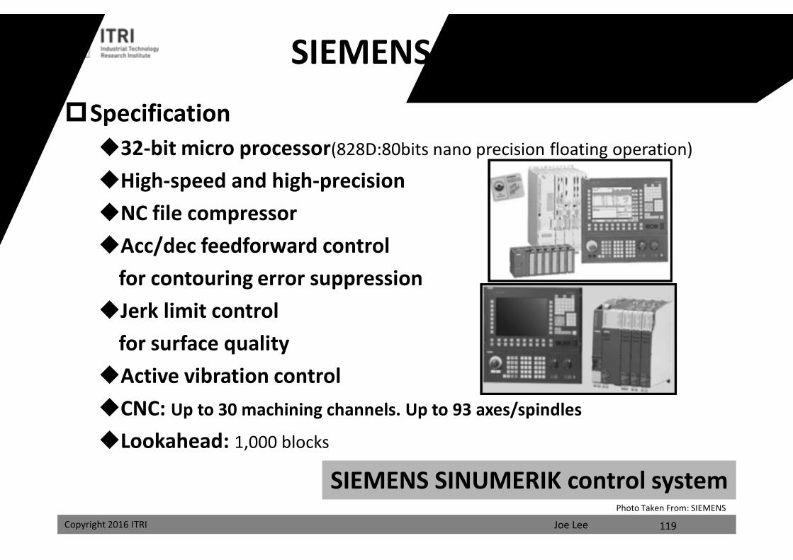
Specification32-bit micro processor(828D:80bits nano precision floating operation)
High-speed and high-precisionNC file compressorAcc/dec feedforward control
for contouring error suppression Jerk limit control
for surface qualityActive vibration controlCNC: Up to 30 machining channels. Up to 93 axes/spindles
Lookahead: 1,000 blocks
SIEMENS SINUMERIK control system
SIEMENS 840 Series
119
Photo Taken From: SIEMENS
課程講義
禁止轉載
Joe LeeCopyright 2016 ITRI Copyright 2016 ITRI
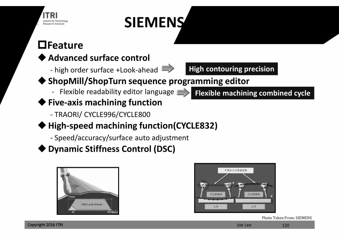
SIEMENS 840D sl SeriesFeatureAdvanced surface control
- high order surface +Look-ahead ShopMill/ShopTurn sequence programming editor
- Flexible readability editor language Five-axis machining function
- TRAORI/ CYCLE996/CYCLE800High-speed machining function(CYCLE832)
- Speed/accuracy/surface auto adjustmentDynamic Stiffness Control (DSC)
120
High contouring precision
Flexible machining combined cycle
Photo Taken From: SIEMENS
課程講義
禁止轉載
Joe LeeCopyright 2016 ITRI Copyright 2016 ITRI
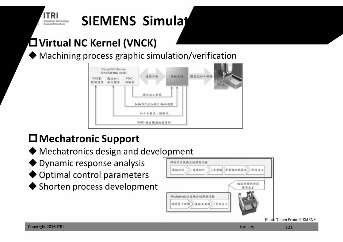
SIEMENS Simulation and ValidationVirtual NC Kernel (VNCK)Machining process graphic simulation/verification
Mechatronic SupportMechatronics design and developmentDynamic response analysisOptimal control parameters Shorten process development
121
Photo Taken From: SIEMENS
課程講義
禁止轉載
Joe LeeCopyright 2016 ITRI Copyright 2016 ITRI
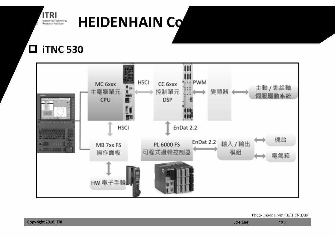
HEIDENHAIN Controls Architecture
iTNC 530
122
Photo Taken From: HEIDENHAIN
課程講義
禁止轉載
Joe LeeCopyright 2016 ITRI
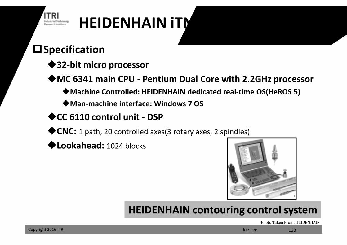
Specification32-bit micro processorMC 6341 main CPU - Pentium Dual Core with 2.2GHz processor
Machine Controlled: HEIDENHAIN dedicated real-time OS(HeROS 5)Man-machine interface: Windows 7 OS
CC 6110 control unit - DSPCNC: 1 path, 20 controlled axes(3 rotary axes, 2 spindles)
Lookahead: 1024 blocks
HEIDENHAIN contouring control system
HEIDENHAIN iTNC530 HSCI Series
123
Photo Taken From: HEIDENHAIN
課程講義
禁止轉載
Joe LeeCopyright 2016 ITRI Copyright 2016 ITRI
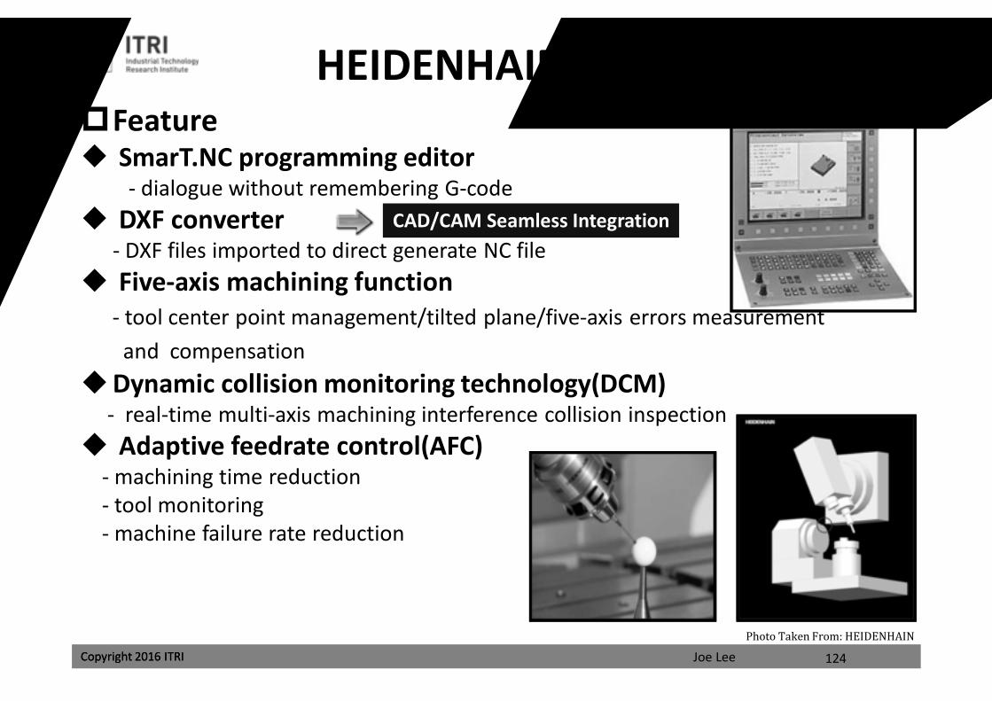
Feature SmarT.NC programming editor
- dialogue without remembering G-code DXF converter
- DXF files imported to direct generate NC file Five-axis machining function
- tool center point management/tilted plane/five-axis errors measurement and compensation
Dynamic collision monitoring technology(DCM)- real-time multi-axis machining interference collision inspection
Adaptive feedrate control(AFC)- machining time reduction- tool monitoring- machine failure rate reduction
HEIDENHAIN iTNC530 Series
124
CAD/CAM Seamless Integration
Photo Taken From: HEIDENHAIN
課程講義
禁止轉載
Joe LeeCopyright 2016 ITRI Copyright 2016 ITRI
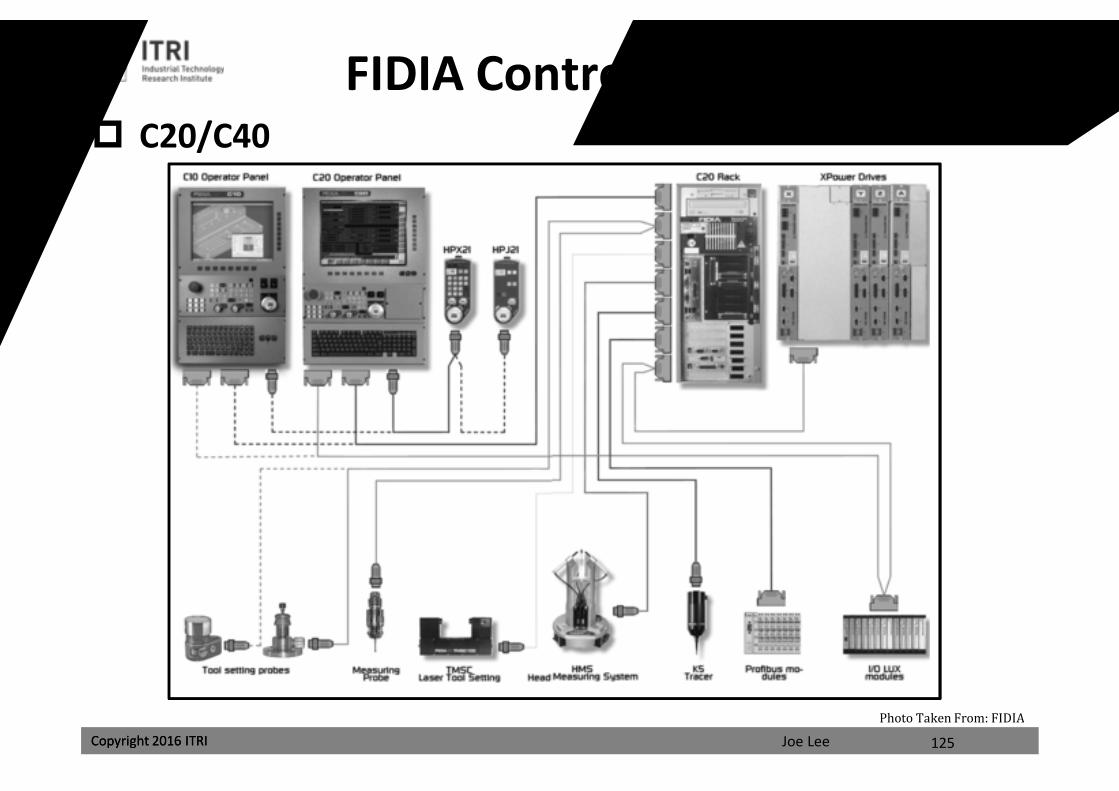
FIDIA Controller Architecture C20/C40
125
Photo Taken From: FIDIA
課程講義
禁止轉載
Joe LeeCopyright 2016 ITRI
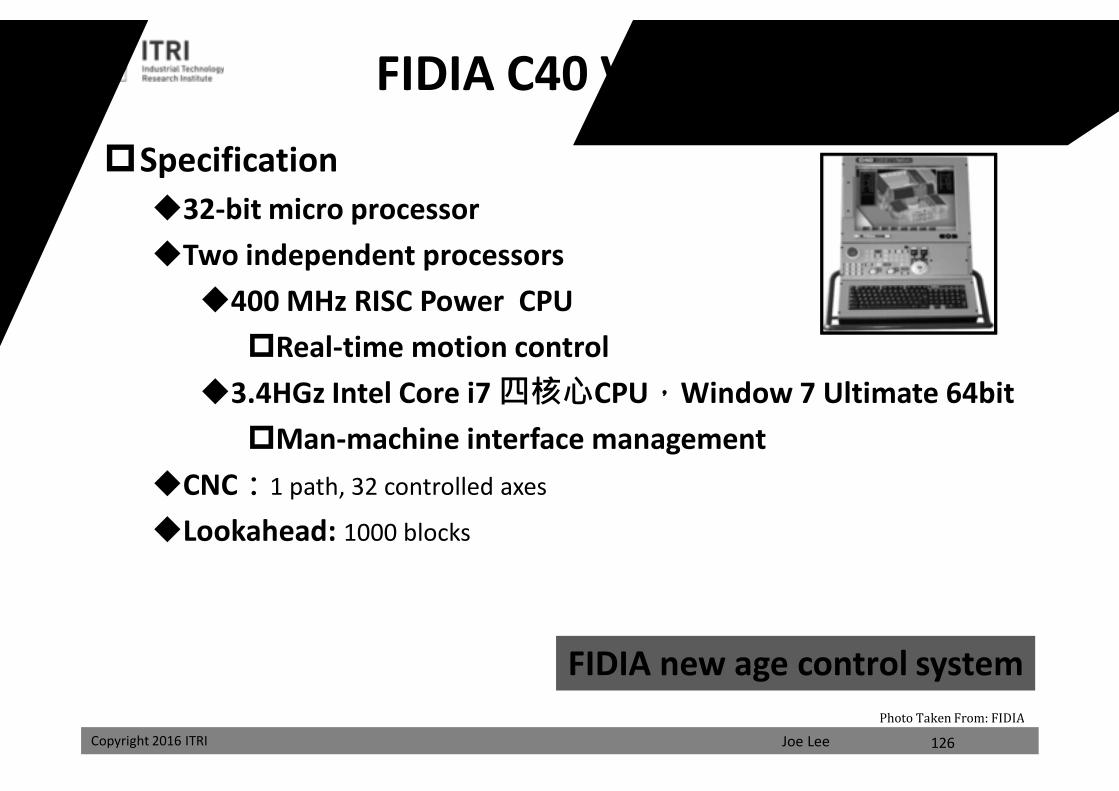
Specification32-bit micro processorTwo independent processors400 MHz RISC Power CPUReal-time motion control
3.4HGz Intel Core i7 四核心CPU,Window 7 Ultimate 64bitMan-machine interface management
CNC:1 path, 32 controlled axes
Lookahead: 1000 blocks
FIDIA new age control system
FIDIA C40 Vision Series
126
Photo Taken From: FIDIA
課程講義
禁止轉載
Joe LeeCopyright 2016 ITRI Copyright 2016 ITRI
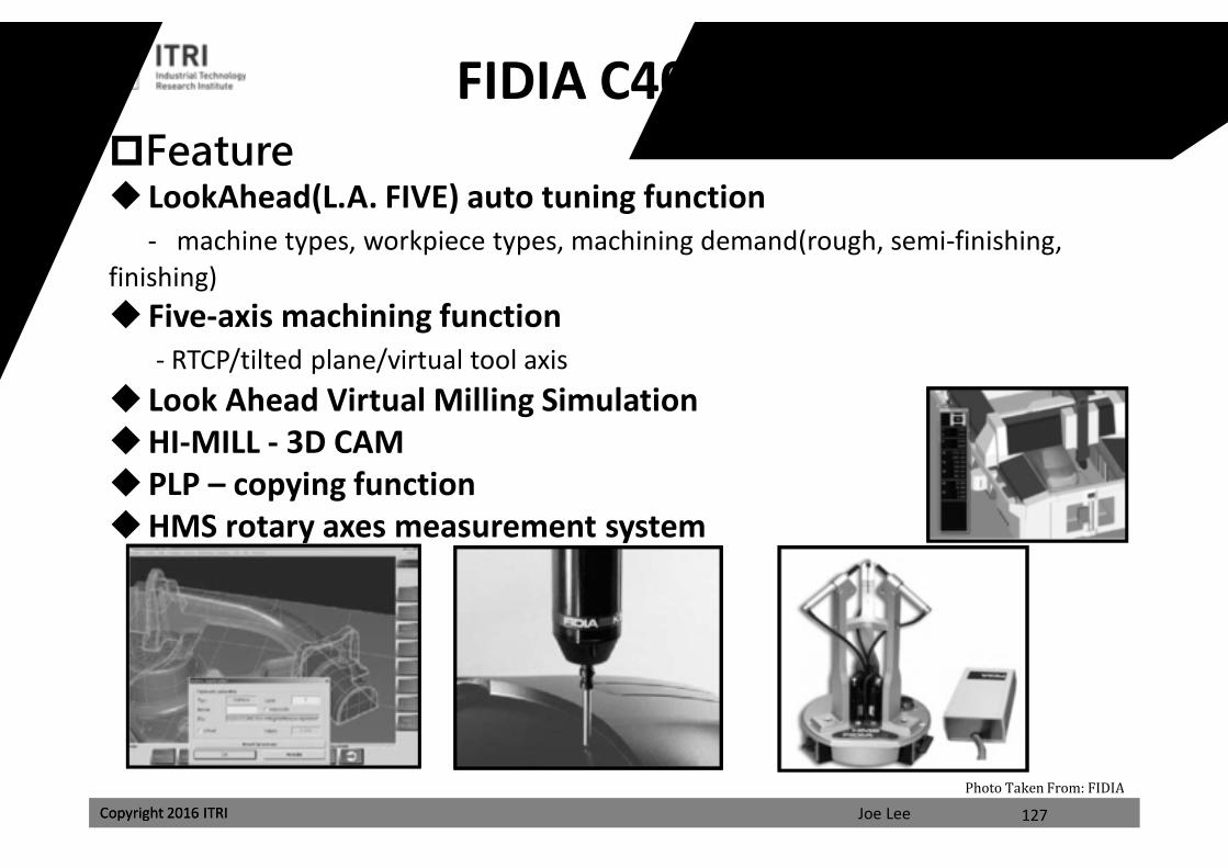
FIDIA C40 Vision SeriesFeature LookAhead(L.A. FIVE) auto tuning function
- machine types, workpiece types, machining demand(rough, semi-finishing, finishing) Five-axis machining function
- RTCP/tilted plane/virtual tool axis Look Ahead Virtual Milling SimulationHI-MILL - 3D CAMPLP – copying functionHMS rotary axes measurement system
127
Photo Taken From: FIDIA
課程講義
禁止轉載
Joe LeeCopyright 2016 ITRI
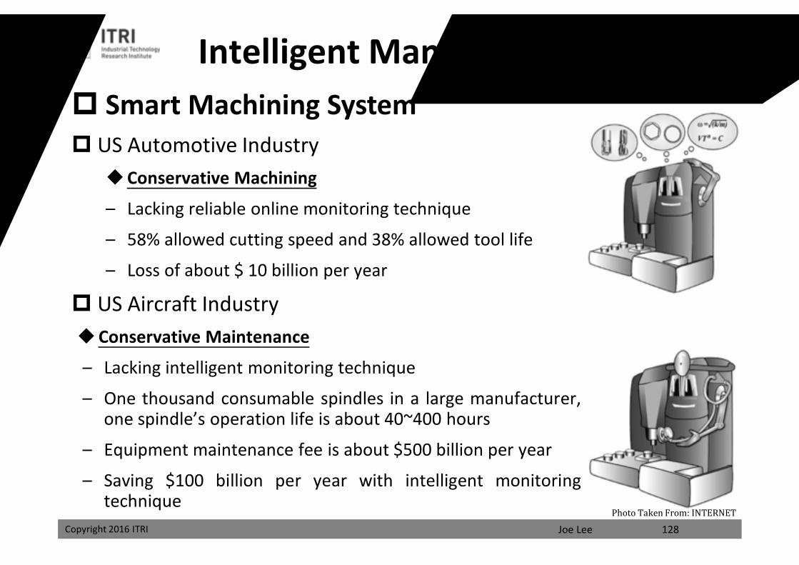
Intelligent Manufacturing System Smart Machining System US Automotive Industry
Conservative Machining
– Lacking reliable online monitoring technique
– 58% allowed cutting speed and 38% allowed tool life
– Loss of about $ 10 billion per year
US Aircraft IndustryConservative Maintenance
– Lacking intelligent monitoring technique
– One thousand consumable spindles in a large manufacturer,one spindle’s operation life is about 40~400 hours
– Equipment maintenance fee is about $500 billion per year
– Saving $100 billion per year with intelligent monitoringtechnique
128Photo Taken From: INTERNET
課程講義
禁止轉載
Joe LeeCopyright 2016 ITRI Copyright 2016 ITRI
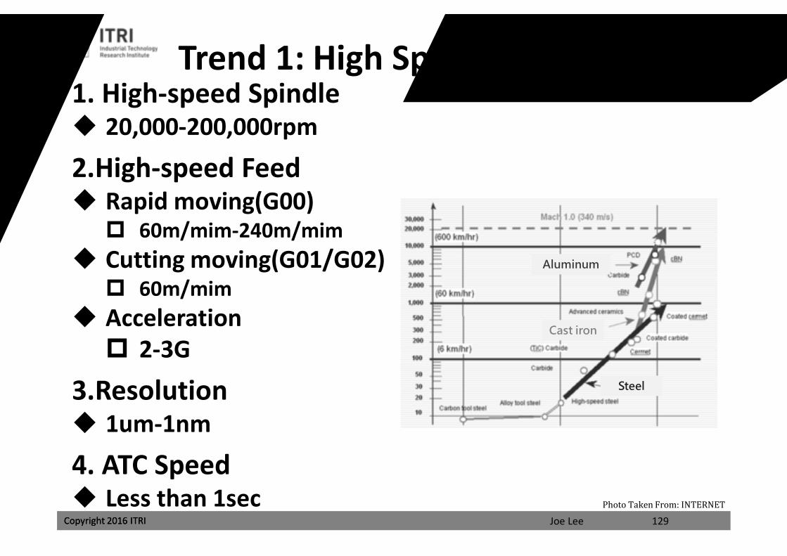
Trend 1: High Speed High Precision1. High-speed Spindle 20,000-200,000rpm
2.High-speed Feed Rapid moving(G00) 60m/mim-240m/mim
Cutting moving(G01/G02) 60m/mim
Acceleration 2-3G
3.Resolution 1um-1nm
4. ATC Speed Less than 1sec
129
Aluminum
Cast iron
Steel
Photo Taken From: INTERNET
課程講義
禁止轉載
Joe LeeCopyright 2016 ITRI Copyright 2016 ITRI
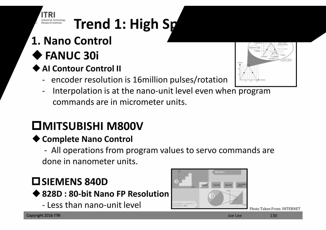
1. Nano Control FANUC 30iAI Contour Control II
- encoder resolution is 16million pulses/rotation- Interpolation is at the nano-unit level even when program
commands are in micrometer units.
MITSUBISHI M800VComplete Nano Control
- All operations from program values to servo commands are done in nanometer units.
SIEMENS 840D828D : 80-bit Nano FP Resolution
- Less than nano-unit level130
Trend 1: High Speed High Precision
Photo Taken From: INTERNET
課程講義
禁止轉載
Joe LeeCopyright 2016 ITRI Copyright 2016 ITRI
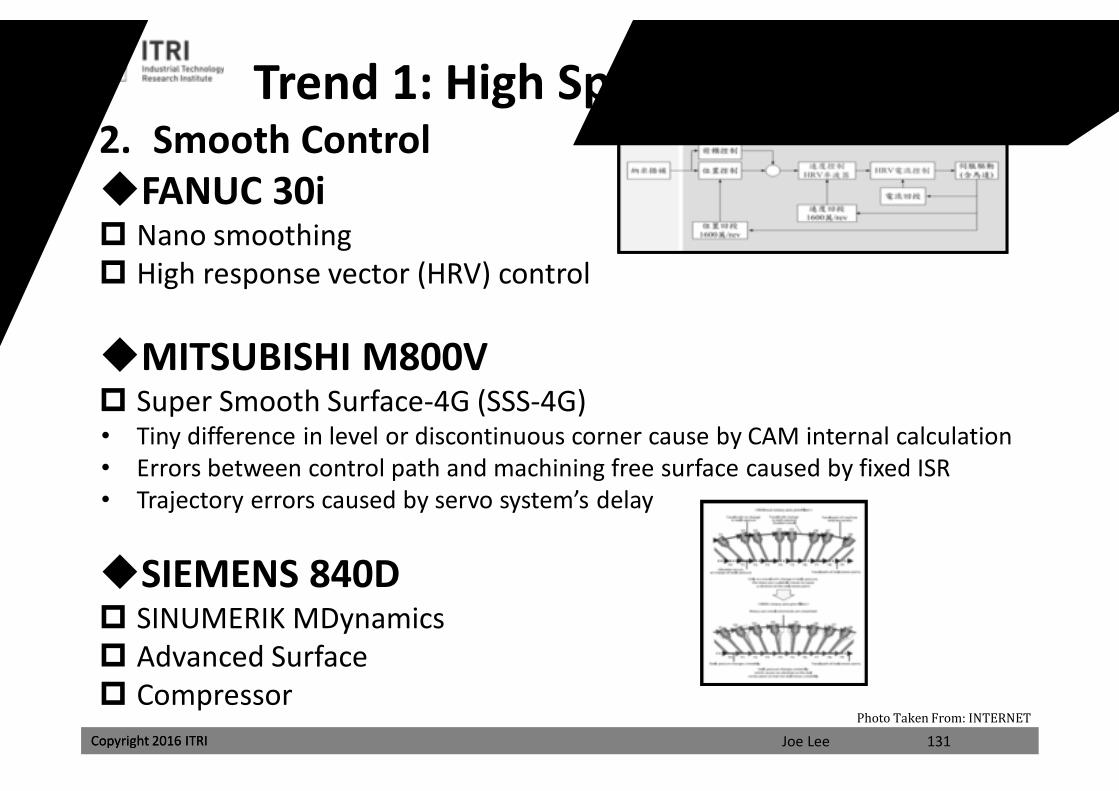
2. Smooth ControlFANUC 30i Nano smoothing High response vector (HRV) control
MITSUBISHI M800V Super Smooth Surface-4G (SSS-4G)• Tiny difference in level or discontinuous corner cause by CAM internal calculation• Errors between control path and machining free surface caused by fixed ISR• Trajectory errors caused by servo system’s delay
SIEMENS 840D SINUMERIK MDynamics Advanced Surface Compressor
131
Trend 1: High Speed High Precision
Photo Taken From: INTERNET
課程講義
禁止轉載
Joe LeeCopyright 2016 ITRI Copyright 2016 ITRI
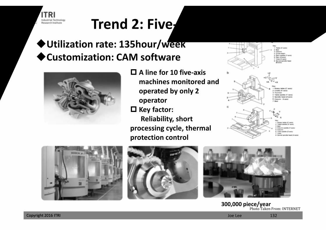
Utilization rate: 135hour/weekCustomization: CAM software
Trend 2: Five-axis Machining
300,000 piece/year
A line for 10 five-axis machines monitored and operated by only 2 operator
Key factor:Reliability, short
processing cycle, thermal protection control
132Photo Taken From: INTERNET
課程講義
禁止轉載
Joe LeeCopyright 2016 ITRI Copyright 2016 ITRI
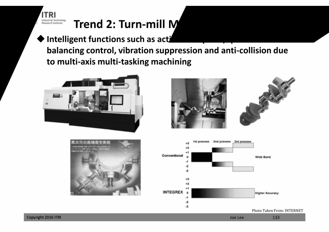
Intelligent functions such as active workpiece/spindle balancing control, vibration suppression and anti-collision due to multi-axis multi-tasking machining
133
Trend 2: Turn-mill Multi-tasking Machining
Photo Taken From: INTERNET
課程講義
禁止轉載
Joe LeeCopyright 2016 ITRI Copyright 2016 ITRI
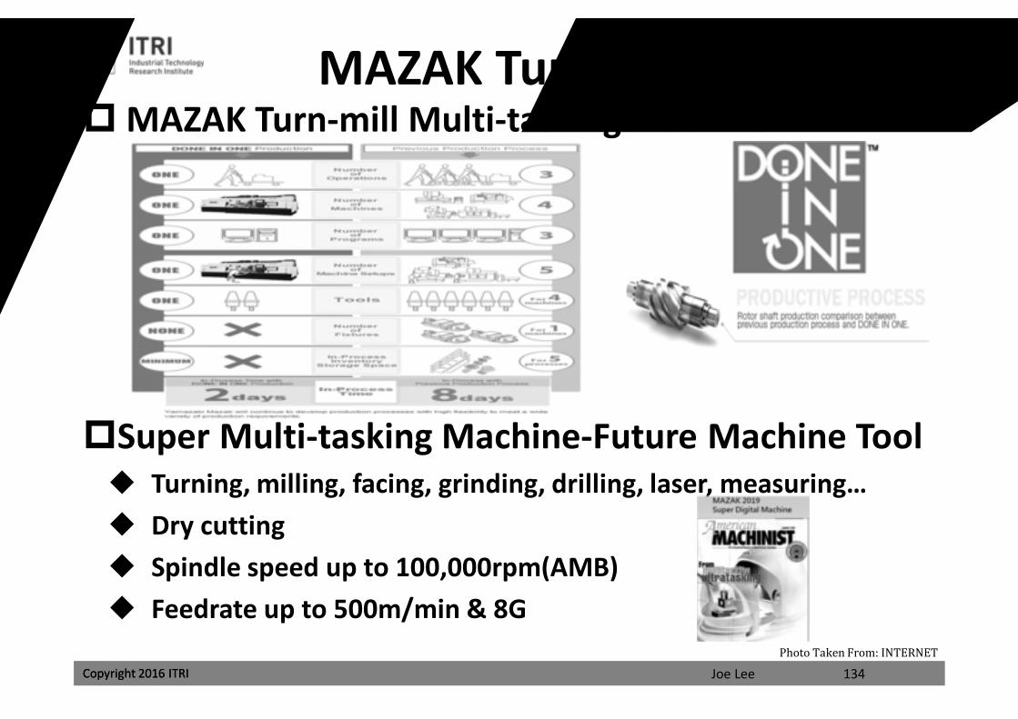
MAZAK Turn-mill Multi-tasking Machine
Super Multi-tasking Machine-Future Machine Tool Turning, milling, facing, grinding, drilling, laser, measuring… Dry cutting Spindle speed up to 100,000rpm(AMB) Feedrate up to 500m/min & 8G
MAZAK Turn-mill Machine
134Photo Taken From: INTERNET
課程講義
禁止轉載
Joe LeeCopyright 2016 ITRI Copyright 2016 ITRI
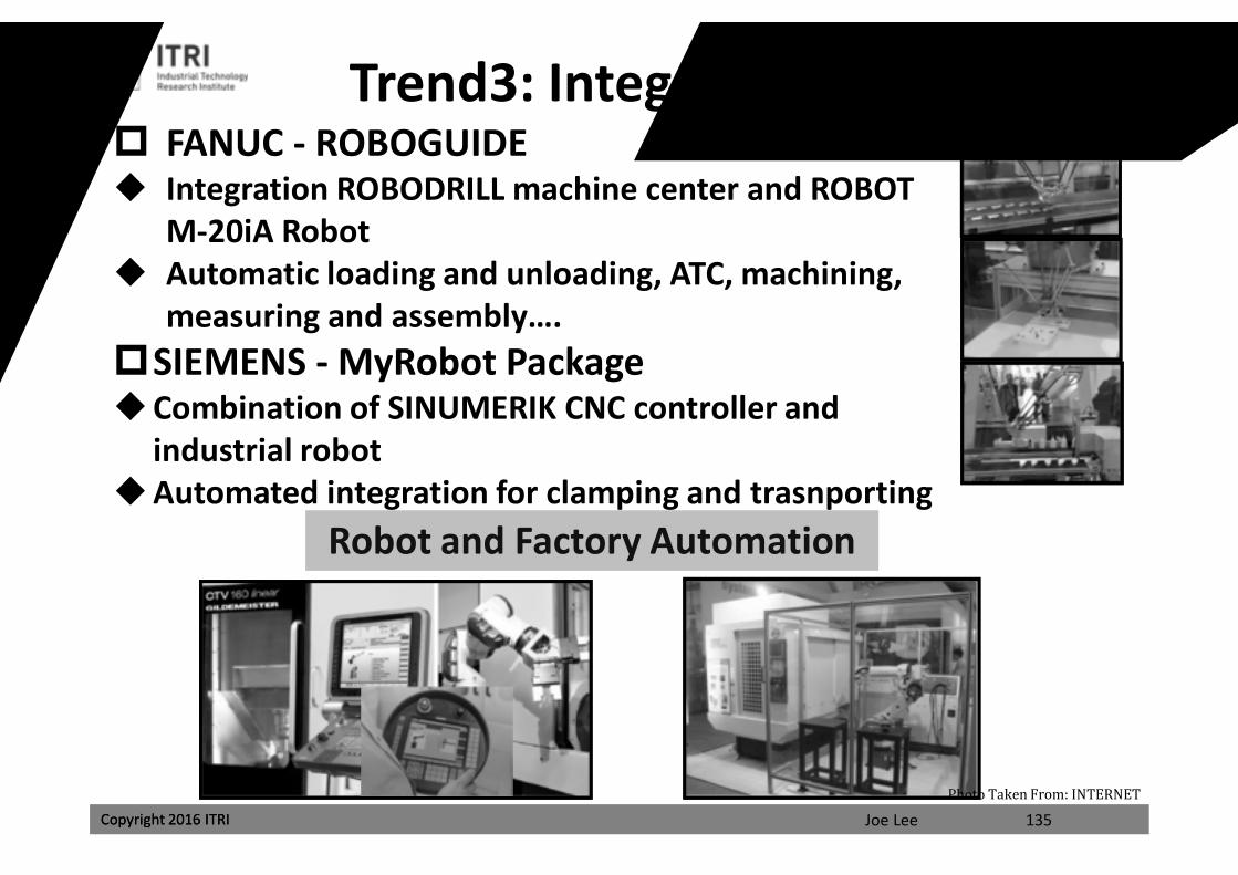
FANUC - ROBOGUIDE Integration ROBODRILL machine center and ROBOT
M-20iA Robot Automatic loading and unloading, ATC, machining,
measuring and assembly….SIEMENS - MyRobot Package Combination of SINUMERIK CNC controller and
industrial robotAutomated integration for clamping and trasnporting
Robot and Factory Automation
Trend3: Integration of Robots
135Photo Taken From: INTERNET
課程講義
禁止轉載
Joe LeeCopyright 2016 ITRI
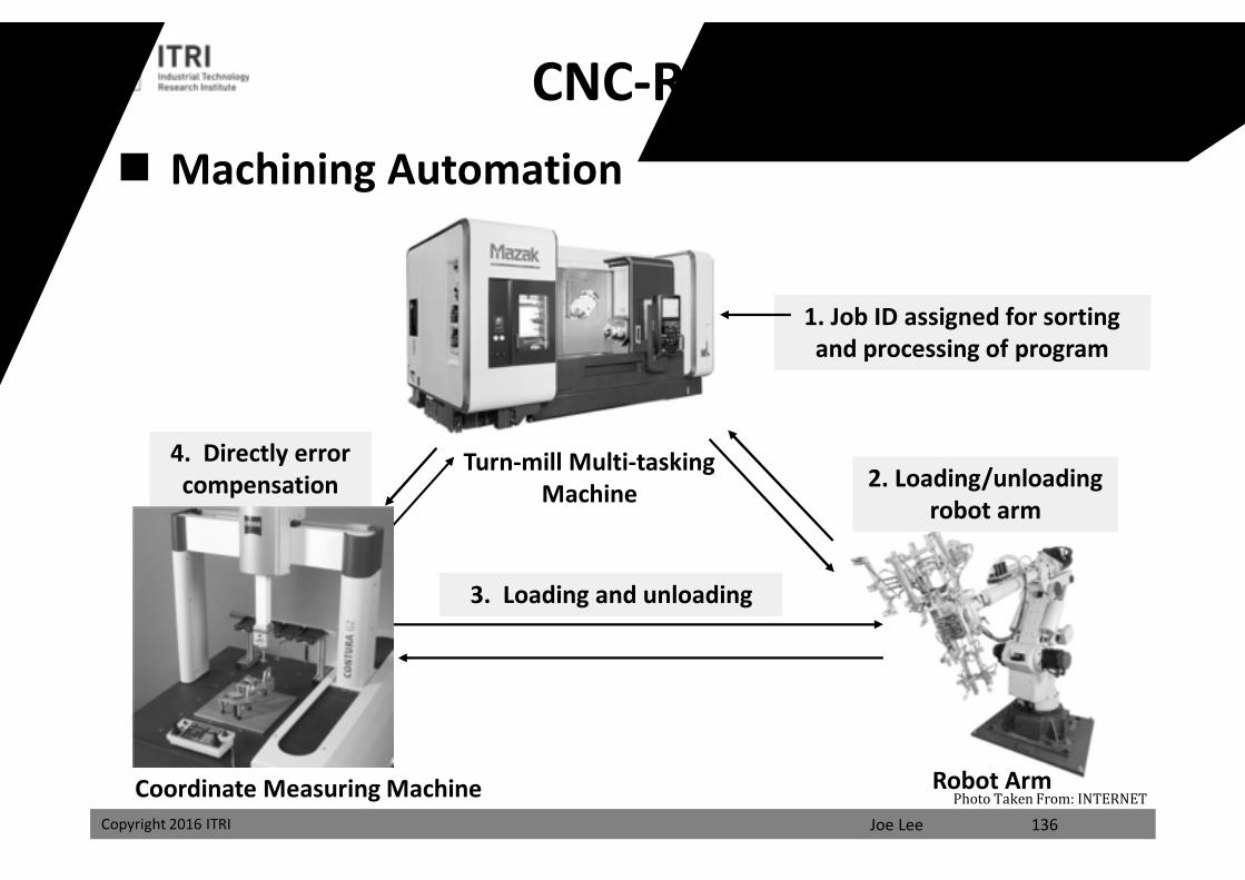
CNC-Robot-CMM Machining Automation
Turn-mill Multi-tasking Machine
3. Loading and unloading
4. Directly error compensation 2. Loading/unloading
robot arm
1. Job ID assigned for sorting and processing of program
Robot ArmCoordinate Measuring Machine136
Photo Taken From: INTERNET
課程講義
禁止轉載
Joe LeeCopyright 2016 ITRI
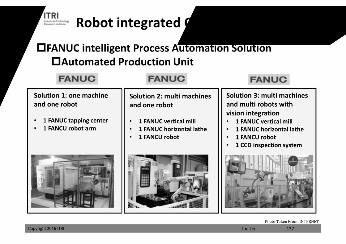
FANUC intelligent Process Automation SolutionAutomated Production Unit
Solution 1: one machine and one robot
• 1 FANUC tapping center• 1 FANCU robot arm
Solution 3: multi machines and multi robots with vision integration• 1 FANUC vertical mill• 1 FANUC horizontal lathe• 1 FANCU robot• 1 CCD inspection system
Solution 2: multi machines and one robot
• 1 FANUC vertical mill• 1 FANUC horizontal lathe• 1 FANCU robot
Robot integrated CNC Control System
137Photo Taken From: INTERNET
課程講義
禁止轉載
Joe LeeCopyright 2016 ITRI Copyright 2016 ITRI
Intelligence for Processing Efficiency and Quality iTNC 530 Adaptive Feed Control 30i Learning Control ITRI Chatter Control
Intelligence for Driving Performance and Connection
30i Servo Guide for optimal feed/spindle control parameters
Intelligence for Remote Monitoring and Fault Diagnosis
840D Condition Monitoring for online monitoring and PLC status
Trend 4: Intelligent Control
138
課程講義
禁止轉載
Joe LeeCopyright 2016 ITRI Copyright 2016 ITRI
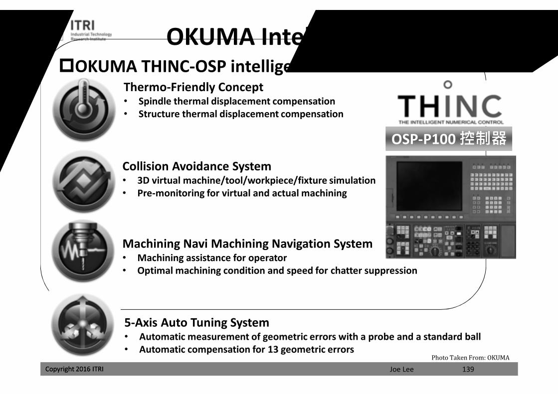
OKUMA THINC-OSP intelligent controlOKUMA Intelligent Control
Thermo-Friendly Concept• Spindle thermal displacement compensation• Structure thermal displacement compensation
Collision Avoidance System• 3D virtual machine/tool/workpiece/fixture simulation• Pre-monitoring for virtual and actual machining
Machining Navi Machining Navigation System• Machining assistance for operator• Optimal machining condition and speed for chatter suppression
5-Axis Auto Tuning System• Automatic measurement of geometric errors with a probe and a standard ball• Automatic compensation for 13 geometric errors
OSP-P100 控制器
139Photo Taken From: OKUMA
課程講義
禁止轉載
Joe LeeCopyright 2016 ITRI Copyright 2016 ITRI
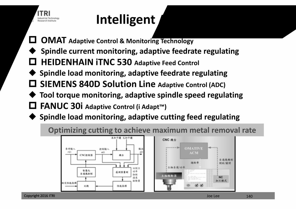
Intelligent Adaptive Control OMAT Adaptive Control & Monitoring Technology Spindle current monitoring, adaptive feedrate regulating HEIDENHAIN iTNC 530 Adaptive Feed Control Spindle load monitoring, adaptive feedrate regulating SIEMENS 840D Solution Line Adaptive Control (ADC) Tool torque monitoring, adaptive spindle speed regulating FANUC 30i Adaptive Control (i Adapt™) Spindle load monitoring, adaptive cutting feed regulating
Optimizing cutting to achieve maximum metal removal rate
140
課程講義
禁止轉載
Joe LeeCopyright 2016 ITRI
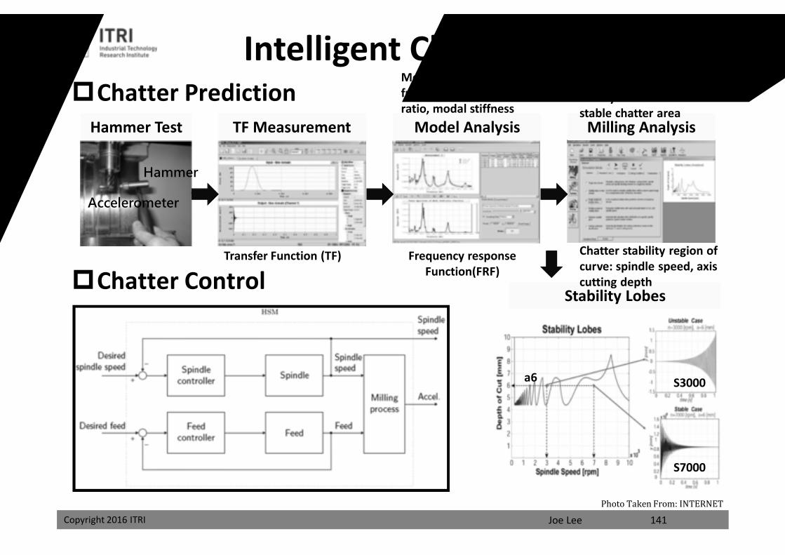
Chatter Prediction
Chatter Control
141
Hammer Test TF Measurement Model Analysis Milling Analysis
Stability Lobes
Accelerometer
Hammer
Frequency response Function(FRF)
S7000
S3000a6
Transfer Function (TF)
Modal fitting: natural frequency, damping ratio, modal stiffness
Regenerative chatter theory: simulation for stable chatter area
Chatter stability region of curve: spindle speed, axis cutting depth
Intelligent Chatter Control
Photo Taken From: INTERNET
課程講義
禁止轉載
Joe LeeCopyright 2016 ITRI
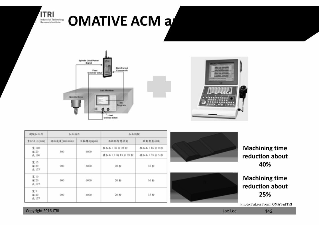
OMATIVE ACM and ITRI Controller
Machining time reduction about
25%
Machining time reduction about
40%
142Photo Taken From: OMAT&ITRI
課程講義
禁止轉載
Joe LeeCopyright 2016 ITRI Copyright 2016 ITRI
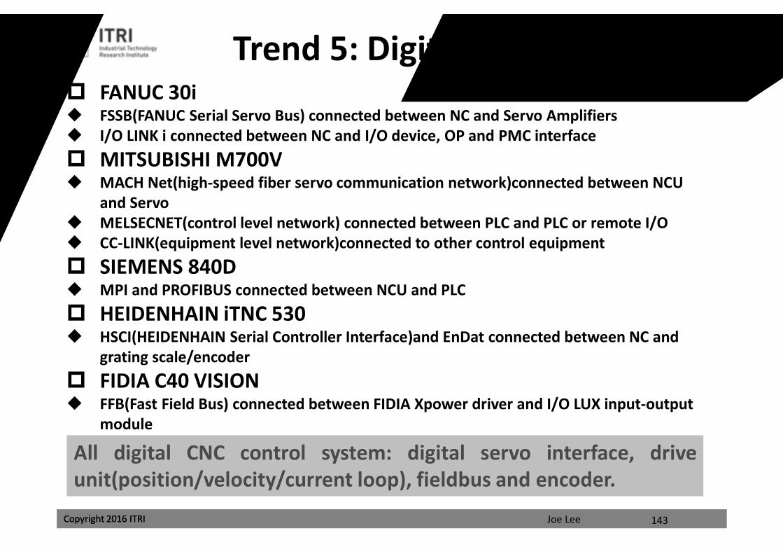
FANUC 30i FSSB(FANUC Serial Servo Bus) connected between NC and Servo Amplifiers I/O LINK i connected between NC and I/O device, OP and PMC interface MITSUBISHI M700V MACH Net(high-speed fiber servo communication network)connected between NCU
and Servo MELSECNET(control level network) connected between PLC and PLC or remote I/O CC-LINK(equipment level network)connected to other control equipment SIEMENS 840D MPI and PROFIBUS connected between NCU and PLC HEIDENHAIN iTNC 530 HSCI(HEIDENHAIN Serial Controller Interface)and EnDat connected between NC and
grating scale/encoder FIDIA C40 VISION FFB(Fast Field Bus) connected between FIDIA Xpower driver and I/O LUX input-output
module
143
All digital CNC control system: digital servo interface, driveunit(position/velocity/current loop), fieldbus and encoder.
Trend 5: Digital Series Servo
課程講義
禁止轉載
Joe LeeCopyright 2016 ITRI
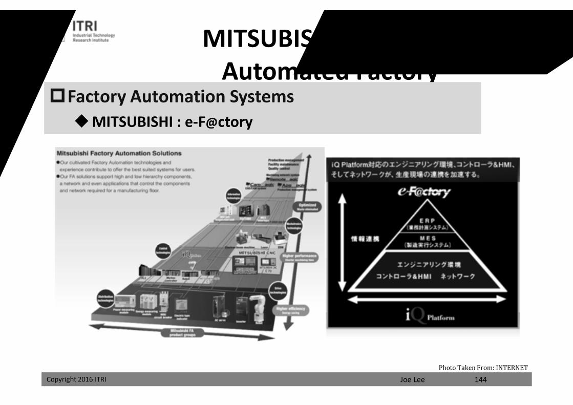
MITSUBISHI Intelligent Automated Factory
Factory Automation SystemsMITSUBISHI : e-F@ctory
144Photo Taken From: INTERNET
課程講義
禁止轉載
Joe LeeCopyright 2016 ITRI
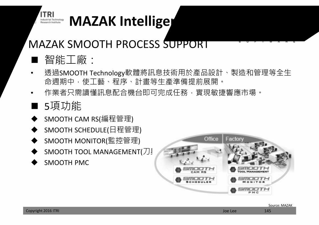
MAZAK Intelligent Network FactoryMAZAK SMOOTH PROCESS SUPPORT 智能工廠:• 透過SMOOTH Technology軟體將訊息技術用於產品設計、製造和管理等全生
命週期中,使工藝、程序、計畫等生產準備提前展開。• 作業者只需讀懂訊息配合機台即可完成任務,實現敏捷響應市場。
5項功能 SMOOTH CAM RS(編程管理) SMOOTH SCHEDULE(日程管理) SMOOTH MONITOR(監控管理) SMOOTH TOOL MANAGEMENT(刀具管理) SMOOTH PMC
Source: MAZAK145
課程講義
禁止轉載
Joe LeeCopyright 2016 ITRI
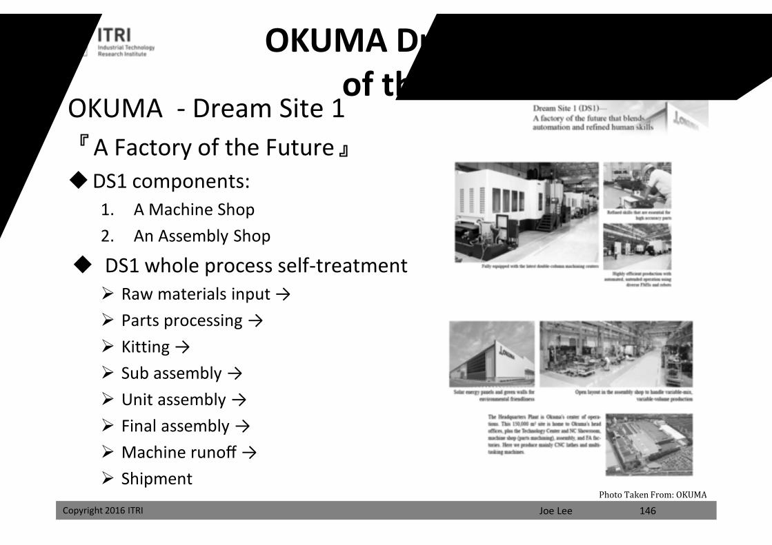
OKUMA Dream Factory of the Future
OKUMA - Dream Site 1『A Factory of the Future』DS1 components:
1. A Machine Shop2. An Assembly Shop
DS1 whole process self-treatment Raw materials input → Parts processing → Kitting → Sub assembly → Unit assembly → Final assembly → Machine runoff → Shipment
146Photo Taken From: OKUMA
課程講義
禁止轉載
Joe LeeCopyright 2016 ITRI Copyright 2016 ITRI
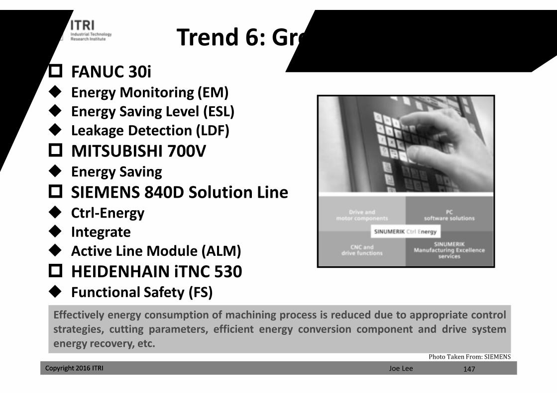
Trend 6: Green and Safety FANUC 30i Energy Monitoring (EM) Energy Saving Level (ESL) Leakage Detection (LDF) MITSUBISHI 700V Energy Saving SIEMENS 840D Solution Line Ctrl-Energy Integrate Active Line Module (ALM) HEIDENHAIN iTNC 530 Functional Safety (FS)
147
Effectively energy consumption of machining process is reduced due to appropriate controlstrategies, cutting parameters, efficient energy conversion component and drive systemenergy recovery, etc.
Photo Taken From: SIEMENS
課程講義
禁止轉載
Joe LeeCopyright 2016 ITRI
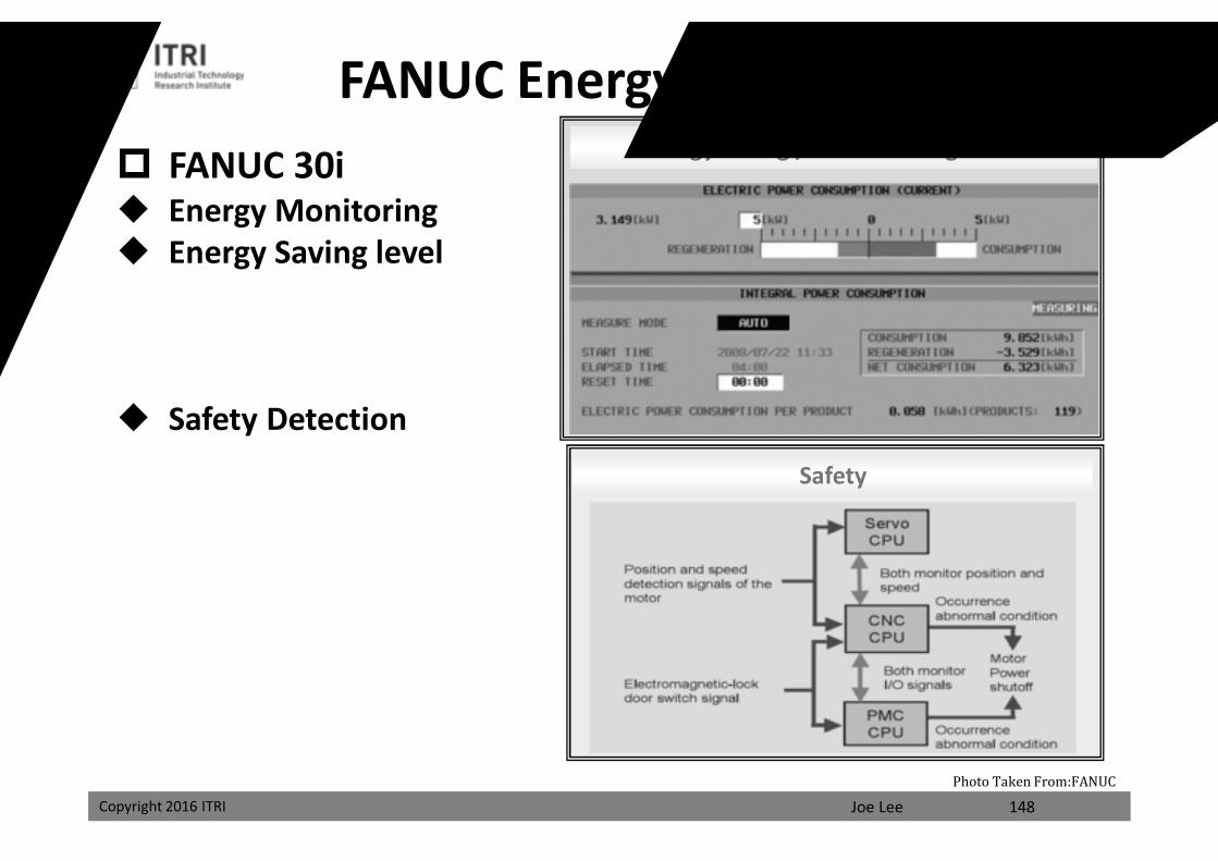
FANUC Energy Saving and SafetyEnergy Saving / Power-saving Mode
Safety
FANUC 30i Energy Monitoring Energy Saving level
Safety Detection
148Photo Taken From:FANUC
課程講義
禁止轉載
Joe LeeCopyright 2016 ITRI Copyright 2016 ITRI
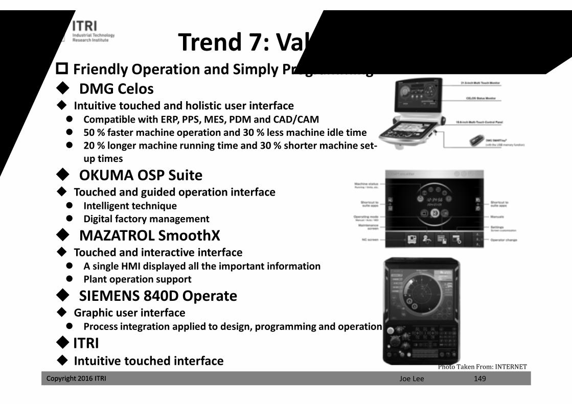
Trend 7: Value-added APP Friendly Operation and Simply Programming DMG Celos Intuitive touched and holistic user interface Compatible with ERP, PPS, MES, PDM and CAD/CAM 50 % faster machine operation and 30 % less machine idle time 20 % longer machine running time and 30 % shorter machine set-
up times
OKUMA OSP Suite Touched and guided operation interface Intelligent technique Digital factory management
MAZATROL SmoothX Touched and interactive interface A single HMI displayed all the important information Plant operation support
SIEMENS 840D Operate Graphic user interface Process integration applied to design, programming and operation
ITRI Intuitive touched interface
149Photo Taken From: INTERNET
課程講義
禁止轉載
Joe LeeCopyright 2016 ITRI Copyright 2016 ITRI
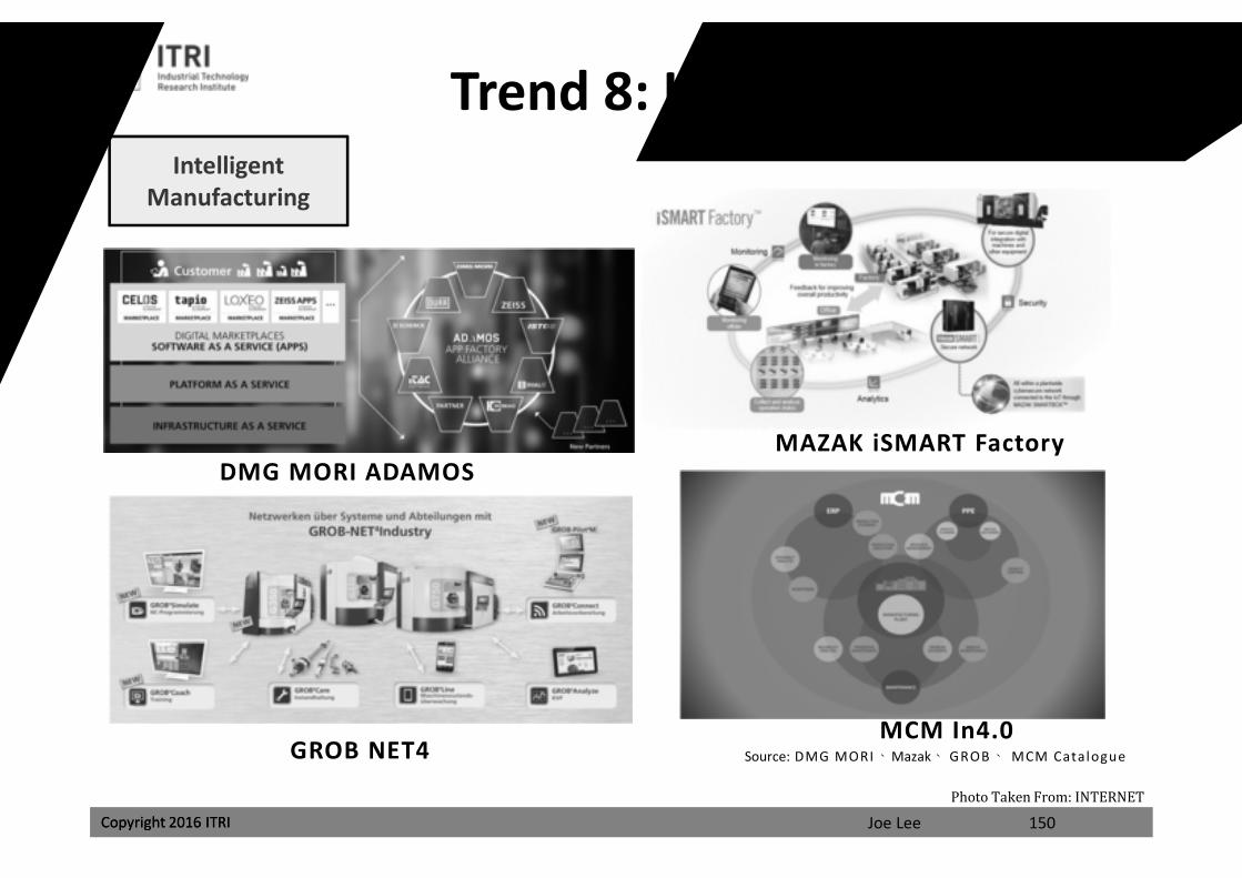
Trend 8: Industry 4.0
150Photo Taken From: INTERNET
DMG MORI ADAMOSMAZAK iSMART Factory
GROB NET4MCM In4.0
Intelligent Manufacturing
Source: DMG MORI、Mazak、 GROB、 MCM Catalogue
課程講義
禁止轉載
Joe LeeCopyright 2016 ITRI Copyright 2016 ITRI
Trend 8: Industry 4.0
151Photo Taken From: INTERNET
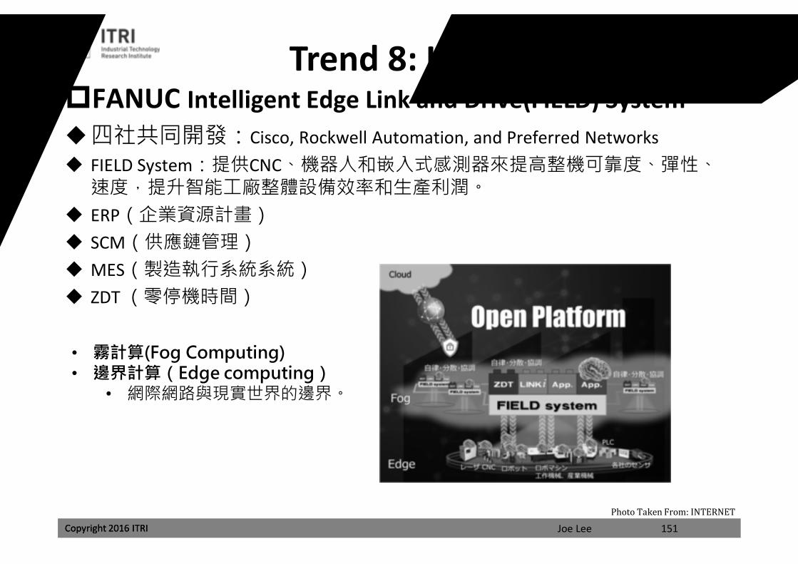
FANUC Intelligent Edge Link and Drive(FIELD) System四社共同開發:Cisco, Rockwell Automation, and Preferred Networks FIELD System:提供CNC、機器人和嵌入式感測器來提高整機可靠度、彈性、
速度,提升智能工廠整體設備效率和生產利潤。 ERP(企業資源計畫) SCM(供應鏈管理) MES(製造執行系統系統) ZDT (零停機時間)
• 霧計算(Fog Computing)• 邊界計算(Edge computing)
• 網際網路與現實世界的邊界。
課程講義
禁止轉載
Joe LeeCopyright 2016 ITRI 152
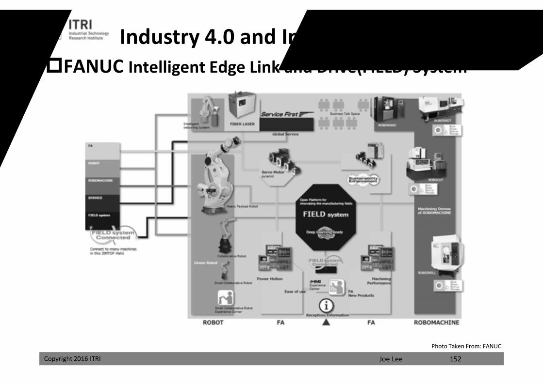
FANUC Intelligent Edge Link and Drive(FIELD) System
Photo Taken From: FANUC
Industry 4.0 and Internet of Things(IoT)
課程講義
禁止轉載
Joe LeeCopyright 2016 ITRI
Thank You for Your Attention!
The End
課程講義
禁止轉載
Related Documents