AC 2011-838: MACHINE DESIGN LAB: USING AUTOMOTIVE TRANS- MISSION EXAMPLES TO REINFORCE UNDERSTANDING OF GEAR TRAIN ANALYSIS Roger A Beardsley, Central Washington University Roger Beardsley is an Assistant Professor in the Mechanical Engineering Technology program at Central Washington University in Ellensburg, WA. He teaches courses in energy related topics (thermodynamics, fluids & heat transfer), along with the second course in the undergraduate sequence in mechanical de- sign. Some of his technical interests include renewable energy, appropriate technology and related design issues. Charles O. Pringle, Central Washington University Charles Pringle is an Assistant Professor in the Mechanical Engineering Technology program at Central Washington University in Ellensburg, WA. He teaches courses in statics, mechanics of materials, and systems simulation, along with the first course in the undergraduate sequence in mechanical design at CWU. Some of his technical interests include systems, renewable energy, and the related design issues. c American Society for Engineering Education, 2011 Page 22.1029.1

Welcome message from author
This document is posted to help you gain knowledge. Please leave a comment to let me know what you think about it! Share it to your friends and learn new things together.
Transcript
AC 2011-838: MACHINE DESIGN LAB: USING AUTOMOTIVE TRANS-MISSION EXAMPLES TO REINFORCE UNDERSTANDING OF GEARTRAIN ANALYSIS
Roger A Beardsley, Central Washington University
Roger Beardsley is an Assistant Professor in the Mechanical Engineering Technology program at CentralWashington University in Ellensburg, WA. He teaches courses in energy related topics (thermodynamics,fluids & heat transfer), along with the second course in the undergraduate sequence in mechanical de-sign. Some of his technical interests include renewable energy, appropriate technology and related designissues.
Charles O. Pringle, Central Washington University
Charles Pringle is an Assistant Professor in the Mechanical Engineering Technology program at CentralWashington University in Ellensburg, WA. He teaches courses in statics, mechanics of materials, andsystems simulation, along with the first course in the undergraduate sequence in mechanical design atCWU. Some of his technical interests include systems, renewable energy, and the related design issues.
c©American Society for Engineering Education, 2011
Page 22.1029.1
Machine Design Lab: Using Automotive Transmission Examples to Reinforce Understanding of Gear Train Analysis
Abstract: In studying mechanical gear train analysis, some students struggle with relatively simple gear design concepts, and virtually all have difficulty with the complexities of planetary gear sets. This paper describes two labs developed for an undergraduate senior level machine design course. One lab uses a three-speed manual synchromesh transmission with parts of the case cut away to demonstrate the operation of the gears, shifting mechanism, bearings, and other aspects of the design. Students then count teeth and analyze the gear ratios using standard gear train analysis methods. The other lab uses a 1924 Ford Model T planetary transmission to observe how planetary gears can create two forward speeds and reverse from constant rotation of the engine. The students analyze the planetary gear set using relative velocity analysis, and the planetary gear set is used to gain insight into basic principles of modern automatic transmissions. The two labs give students hands-on learning experience that clarifies difficult concepts and teaches students basic principles of gear train design, operation, and analysis. Introduction When teaching Mechanical Engineering Technology topics, learning is facilitated by introducing concepts based on familiar objects. Many MET students have the curiosity to take things apart to see how they work. Since everyone is familiar with automobiles, examples of automotive machinery pique student interest. In the Mechanical Engineering Technology (MET) program at Central Washington University (CWU), the two-quarter sequence in Mechanical Design includes weekly lab activities. Two of the lab activities analyze automotive transmissions. The two transmission labs utilize a three-speed manual shift transmission and a planetary transmission. The three-speed transmission illustrates the operation of manual shift transmissions (with synchros, sliding gears and collars, and dry plate clutch) while the planetary transmission illustrates a simplified version of the operation of automatic transmissions (shifting using brake bands and a wet plate clutch). By "reverse engineering" these transmissions, many gear design concepts make better intuitive sense to students. Gear design jargon can be complex. Over 80 terms are used to define gear geometry 1. In analyzing the transmissions in our lab, a number of the terms take on deeper meaning. For example, students can measure the gear diameter and count teeth to calculate the Diametral Pitch (Pd), and can use that information to predict the distance between centers of two gears and Pitch Diameter (Dp) for each gear. By making these calculations students get a better sense of the distinction between these two basic terms than they would from memorizing the concepts and definitions alone. In these two labs, many mechanical topics are addressed. Gear ratios are analyzed using two different analysis methods: standard gear train relationships and relative velocity methods. Wet plate, dry plate, and cone type clutches are observed and discussed, as is the operation of band brakes. Ball bearings, needle bearings, thrust washers and grooved bronze bushings are also used in these transmissions, and can be discussed in the context of where they are used and why they
Page 22.1029.2
are chosen for those applications. Discussions about the torque multiplication effect, friction and power losses are also facilitated. Lab Activity Outline In the introduction to each lab, students are given information about the function of the transmission, how gear ratios are selected, and other related machine elements such as bearings and clutches. They are then assigned a number of questions to research, not least of which is calculating the input : output ratio for each selected gear. To accomplish their task students must prepare a concise technical memo describing the transmission operation, including appropriate technical data. Data and calculations are included in attached pages to support statements in the report. Lab #1: The Three-Speed Lab The transmission example used is a Ford "Toploader" style three-speed manual transmission, as used on late 1950s F series pickups with steering column gear selector ("three on the tree"). The two shift arms are intact on the side of the transmission case so their operation can be observed. The top cover (through which the assembled gears are "loaded") is removed, and in addition two other sections of the transmission housing have been removed (using a die grinder cutting wheel) to reveal the main lay shaft and the reverse lay shaft. A plywood faceplate has been attached to the transmission front, along with a support for the rear to support the transmission as it is turned over for viewing, and to protect the tabletop that it rests on. Figure 1 shows the three-speed transmission with its mounting. For the lab activity an introduction explains the general operation of shift linkages and other mechanical aspects of the transmission operation. Students are then assigned a task of determining the input : output ratio and explaining the operation in a memo format lab report. In performing the analysis of the three-speed transmission, students count teeth on all the gears, observe how the gears mesh together, and observe the action of the shifting mechanisms. They then calculate gear train ratios and describe the power path through the transmission, along with the function of the synchronizers. They are also asked to make observations about different bearing types being used and characteristics of the gear types being used. In the three forward gears, constant mesh helical gears are used. Helical gears are quieter in operation than straight spur gears. It is interesting to note that the helix angle of the gears does not appear to be consistent. Helical gears will generate a thrust load, and it is possible to calculate the thrust load generated by a gear pair. Since two gear pairs are typically used, the thrust generated by one gear pair is opposed by the other gear pair with the helix angle varying to balance the thrust loads on the lay shaft. Figure 2 shows the main shaft with gears of varying helix angle.
Page 22.1029.3
Figure 1: Ford "Toploader" Three Speed Transmission
Figure 2: Transmission Main Shaft with Varying Helix Angles
Page 22.1029.4
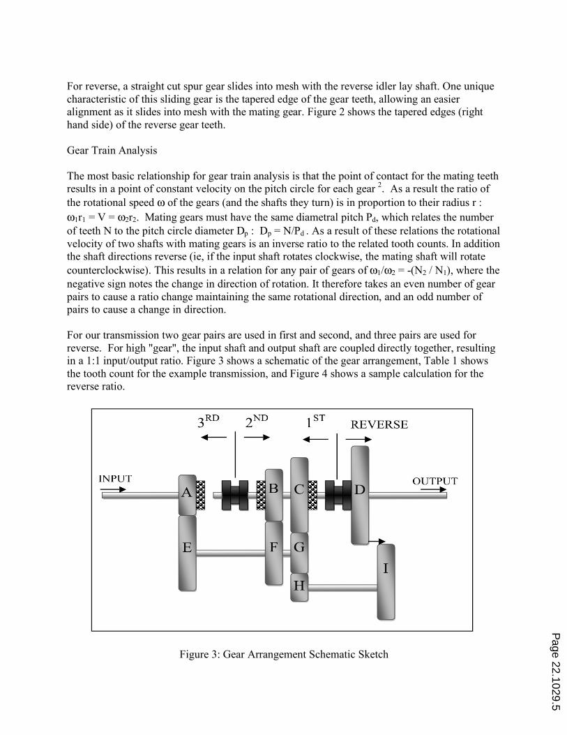
For reverse, a straight cut spur gear slides into mesh with the reverse idler lay shaft. One unique characteristic of this sliding gear is the tapered edge of the gear teeth, allowing an easier alignment as it slides into mesh with the mating gear. Figure 2 shows the tapered edges (right hand side) of the reverse gear teeth. Gear Train Analysis The most basic relationship for gear train analysis is that the point of contact for the mating teeth results in a point of constant velocity on the pitch circle for each gear 2. As a result the ratio of the rotational speed ω of the gears (and the shafts they turn) is in proportion to their radius r : ω1r1 = V = ω2r2. Mating gears must have the same diametral pitch Pd, which relates the number of teeth N to the pitch circle diameter Dp : Dp = N/Pd . As a result of these relations the rotational velocity of two shafts with mating gears is an inverse ratio to the related tooth counts. In addition the shaft directions reverse (ie, if the input shaft rotates clockwise, the mating shaft will rotate counterclockwise). This results in a relation for any pair of gears of ω1/ω2 = -(N2 / N1), where the negative sign notes the change in direction of rotation. It therefore takes an even number of gear pairs to cause a ratio change maintaining the same rotational direction, and an odd number of pairs to cause a change in direction. For our transmission two gear pairs are used in first and second, and three pairs are used for reverse. For high "gear", the input shaft and output shaft are coupled directly together, resulting in a 1:1 input/output ratio. Figure 3 shows a schematic of the gear arrangement, Table 1 shows the tooth count for the example transmission, and Figure 4 shows a sample calculation for the reverse ratio.
Figure 3: Gear Arrangement Schematic Sketch
Page 22.1029.5
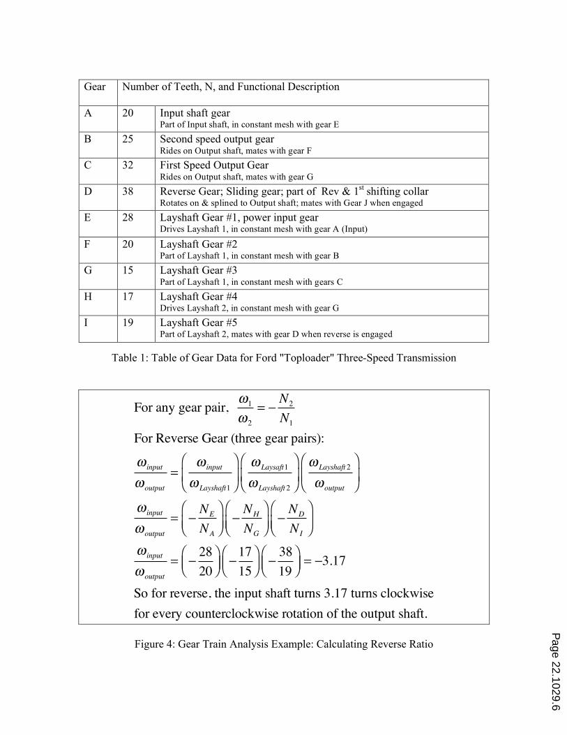
Gear Number of Teeth, N, and Functional Description
A 20 Input shaft gear Part of Input shaft, in constant mesh with gear E
B 25 Second speed output gear Rides on Output shaft, mates with gear F
C 32 First Speed Output Gear Rides on Output shaft, mates with gear G
D 38 Reverse Gear; Sliding gear; part of Rev & 1st shifting collar Rotates on & splined to Output shaft; mates with Gear J when engaged
E 28 Layshaft Gear #1, power input gear Drives Layshaft 1, in constant mesh with gear A (Input)
F 20 Layshaft Gear #2 Part of Layshaft 1, in constant mesh with gear B
G 15 Layshaft Gear #3 Part of Layshaft 1, in constant mesh with gears C
H 17 Layshaft Gear #4 Drives Layshaft 2, in constant mesh with gear G
I 19 Layshaft Gear #5 Part of Layshaft 2, mates with gear D when reverse is engaged
Table 1: Table of Gear Data for Ford "Toploader" Three-Speed Transmission
For any gear pair, !1
!2
= "N2
N1
For Reverse Gear (three gear pairs):
! input
!output
=! input
! Layshaft1
#
$%
&
'(
! Laysaft1
! Layshaft2
#
$%
&
'(
! Layshaft2
!output
#
$%
&
'(
! input
!output
= "NE
NA
#
$%&
'("NH
NG
#
$%&
'("ND
NI
#
$%&
'(
! input
!output
= "28
20
#$%
&'(
"17
15
#$%
&'(
"38
19
#$%
&'(= "3.17
So for reverse, the input shaft turns 3.17 turns clockwise
for every counterclockwise rotation of the output shaft.
Figure 4: Gear Train Analysis Example: Calculating Reverse Ratio
Page 22.1029.6
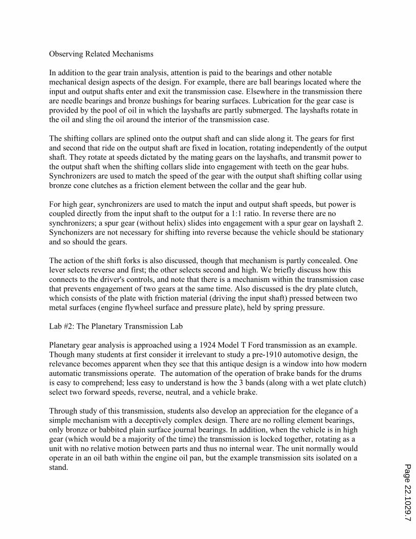
Observing Related Mechanisms In addition to the gear train analysis, attention is paid to the bearings and other notable mechanical design aspects of the design. For example, there are ball bearings located where the input and output shafts enter and exit the transmission case. Elsewhere in the transmission there are needle bearings and bronze bushings for bearing surfaces. Lubrication for the gear case is provided by the pool of oil in which the layshafts are partly submerged. The layshafts rotate in the oil and sling the oil around the interior of the transmission case. The shifting collars are splined onto the output shaft and can slide along it. The gears for first and second that ride on the output shaft are fixed in location, rotating independently of the output shaft. They rotate at speeds dictated by the mating gears on the layshafts, and transmit power to the output shaft when the shifting collars slide into engagement with teeth on the gear hubs. Synchronizers are used to match the speed of the gear with the output shaft shifting collar using bronze cone clutches as a friction element between the collar and the gear hub. For high gear, synchronizers are used to match the input and output shaft speeds, but power is coupled directly from the input shaft to the output for a 1:1 ratio. In reverse there are no synchronizers; a spur gear (without helix) slides into engagement with a spur gear on layshaft 2. Synchonizers are not necessary for shifting into reverse because the vehicle should be stationary and so should the gears. The action of the shift forks is also discussed, though that mechanism is partly concealed. One lever selects reverse and first; the other selects second and high. We briefly discuss how this connects to the driver's controls, and note that there is a mechanism within the transmission case that prevents engagement of two gears at the same time. Also discussed is the dry plate clutch, which consists of the plate with friction material (driving the input shaft) pressed between two metal surfaces (engine flywheel surface and pressure plate), held by spring pressure. Lab #2: The Planetary Transmission Lab Planetary gear analysis is approached using a 1924 Model T Ford transmission as an example. Though many students at first consider it irrelevant to study a pre-1910 automotive design, the relevance becomes apparent when they see that this antique design is a window into how modern automatic transmissions operate. The automation of the operation of brake bands for the drums is easy to comprehend; less easy to understand is how the 3 bands (along with a wet plate clutch) select two forward speeds, reverse, neutral, and a vehicle brake. Through study of this transmission, students also develop an appreciation for the elegance of a simple mechanism with a deceptively complex design. There are no rolling element bearings, only bronze or babbited plain surface journal bearings. In addition, when the vehicle is in high gear (which would be a majority of the time) the transmission is locked together, rotating as a unit with no relative motion between parts and thus no internal wear. The unit normally would operate in an oil bath within the engine oil pan, but the example transmission sits isolated on a stand.
Page 22.1029.7
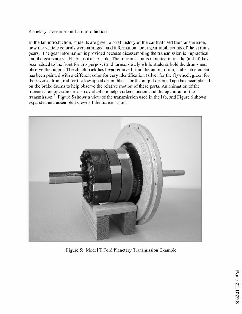
Planetary Transmission Lab Introduction In the lab introduction, students are given a brief history of the car that used the transmission, how the vehicle controls were arranged, and information about gear tooth counts of the various gears. The gear information is provided because disassembling the transmission is impractical and the gears are visible but not accessible. The transmission is mounted in a lathe (a shaft has been added to the front for this purpose) and turned slowly while students hold the drums and observe the output. The clutch pack has been removed from the output drum, and each element has been painted with a different color for easy identification (silver for the flywheel, green for the reverse drum, red for the low speed drum, black for the output drum). Tape has been placed on the brake drums to help observe the relative motion of these parts. An animation of the transmission operation is also available to help students understand the operation of the transmission 3. Figure 5 shows a view of the transmission used in the lab, and Figure 6 shows expanded and assembled views of the transmission.
Figure 5: Model T Ford Planetary Transmission Example
Page 22.1029.8
Figure 6: Model T Ford Transmission Expanded View 4 Following the lab introduction and the lathe demonstration, students must research the design and determine the diametral pitch of the gears (counting teeth and measuring a sample triple gear), determine the center-to-center design distance for the planet gear pins, and develop the calculations for the low speed and reverse gear ratios. A concise lab memo is assigned which outlines the speed ratios with a description of how the transmission operates, including how operator controls were used. Attached to the lab memo is an appendix supporting the gear ratio calculations and supporting information for statements they make in the report. Gear Ratio Analysis for Planetary Transmission To analyze this planetary transmission, the gear train analysis method used in the previous lab does not work because the pin on which the planet "triple gears" rotate is also in motion. It is still true that the point of contact between two gears has the same velocity. The analysis for this planetary gear set requires using instantaneous velocity and relative velocity analysis that students were introduced to in a dynamics course. Developing the speed ratio equation requires some creative algebra substitutions, but the result is elegantly simple. The drum bores all nest on a shaft mounted to the flywheel that passes through the drums to the clutch pack in the output drum. When the clutch pack is compressed, the transmission rotates as a unit (no relative motion) and the input:output ratio is 1:1 (high gear). In high gear, with no relative motion there is also no wear on the gears or bushings in the transmission.
Page 22.1029.9
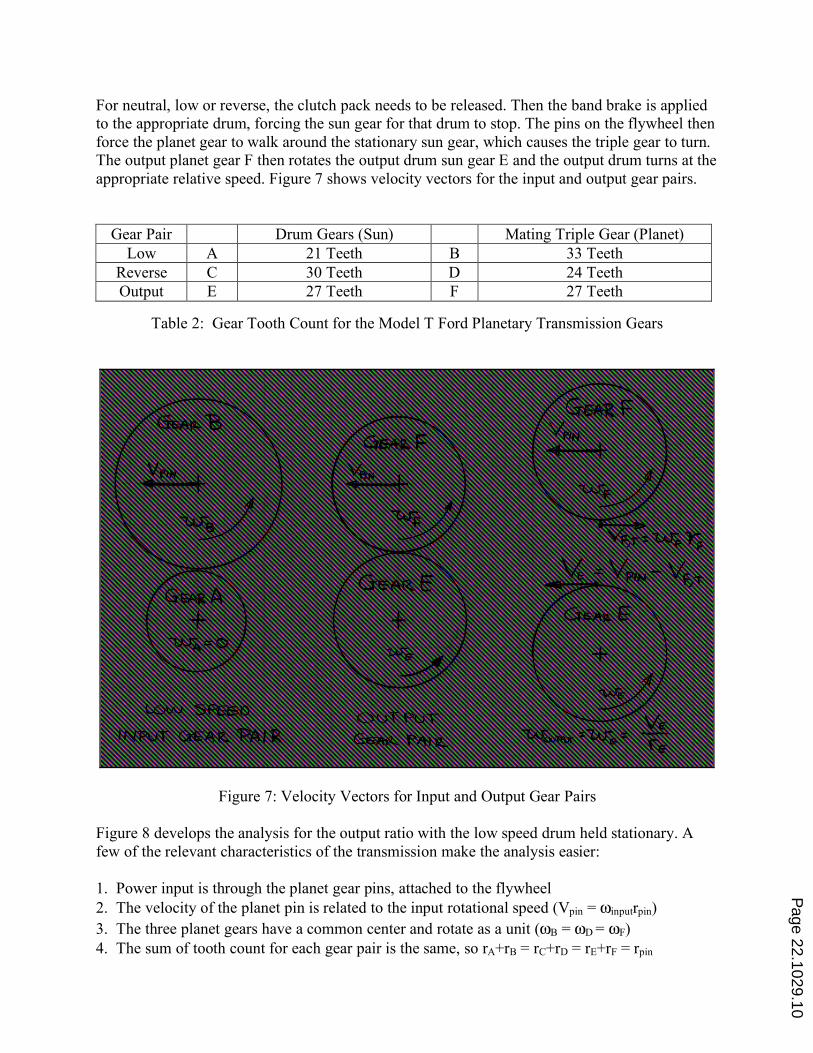
For neutral, low or reverse, the clutch pack needs to be released. Then the band brake is applied to the appropriate drum, forcing the sun gear for that drum to stop. The pins on the flywheel then force the planet gear to walk around the stationary sun gear, which causes the triple gear to turn. The output planet gear F then rotates the output drum sun gear E and the output drum turns at the appropriate relative speed. Figure 7 shows velocity vectors for the input and output gear pairs.
Gear Pair Drum Gears (Sun) Mating Triple Gear (Planet) Low A 21 Teeth B 33 Teeth
Reverse C 30 Teeth D 24 Teeth Output E 27 Teeth F 27 Teeth
Table 2: Gear Tooth Count for the Model T Ford Planetary Transmission Gears
Figure 7: Velocity Vectors for Input and Output Gear Pairs Figure 8 develops the analysis for the output ratio with the low speed drum held stationary. A few of the relevant characteristics of the transmission make the analysis easier: 1. Power input is through the planet gear pins, attached to the flywheel 2. The velocity of the planet pin is related to the input rotational speed (Vpin = ωinputrpin) 3. The three planet gears have a common center and rotate as a unit (ωB = ωD = ωF) 4. The sum of tooth count for each gear pair is the same, so rA+rB = rC+rD = rE+rF = rpin
Page 22.1029.10
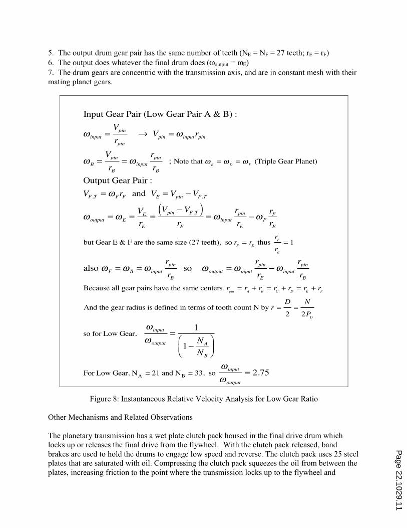
5. The output drum gear pair has the same number of teeth (NE = NF = 27 teeth; rE = rF) 6. The output does whatever the final drum does (ωoutput = ωE) 7. The drum gears are concentric with the transmission axis, and are in constant mesh with their mating planet gears.
Input Gear Pair (Low Gear Pair A & B) :
! input =Vpin
rpin " Vpin =! inputrpin
!B =Vpin
rB=! input
rpin
rB ; Note that !
B= !
D= !
F (Triple Gear Planet)
Output Gear Pair :
VF ,T =!FrF and VE = Vpin #VF ,T
!output =!E =VE
rE=Vpin #VF ,T( )
rE=! input
rpin
rE#!F
rF
rE
but Gear E & F are the same size (27 teeth), so rF= r
E thus
rF
rE
= 1
also !F =!B =! input
rpin
rB so !output =! input
rpin
rE#! input
rpin
rB
Because all gear pairs have the same centers, rpin
= rA+ r
B= r
C+ r
D= r
E+ r
F
And the gear radius is defined in terms of tooth count N by r =D
2=
N
2PD
so for Low Gear, ! input
!output
=1
1#NA
NB
$%&
'()
For Low Gear, NA = 21 and NB = 33, so ! input
!output
= 2.75
Figure 8: Instantaneous Relative Velocity Analysis for Low Gear Ratio
Other Mechanisms and Related Observations The planetary transmission has a wet plate clutch pack housed in the final drive drum which locks up or releases the final drive from the flywheel. With the clutch pack released, band brakes are used to hold the drums to engage low speed and reverse. The clutch pack uses 25 steel plates that are saturated with oil. Compressing the clutch pack squeezes the oil from between the plates, increasing friction to the point where the transmission locks up to the flywheel and
Page 22.1029.11
provides direct drive. This type of clutch is commonly used today in motorcycles and most automotive automatic transmissions. Simplicity of the Model T design is highlighted by noting the limited number of fasteners used in the transmission. One square key and one setscrew fasten the disk drum to the transmission shaft that holds the whole transmission assembly together. The only other key is used to transmit torque from gear E to the brake (aka output) drum shaft. Six bolts fasten the driving plate to the output drum. A single pin holds the clutch spring thrust ring support, which contains the spring that compresses the clutch pack. The planet gears rotate on pins that are press fit into the flywheel, with no other mechanical restraints other than the setscrew in the disk drum. The entire transmission (excluding the clutch and brake band actuator linkages) uses seven threaded fasteners, one pin, and two keys. This transmission has no rolling element bearings. Bronze bushings are used for the planet and drum bearing surfaces. Lubrication of these bushings comes from the splash lubrication of the transmission provided by the flywheel, which rotates in the oil sump and slings oil over the interior of the transmission housing and into gutters which feed oil to the crankshaft and camshaft bearings of the engine. Students are asked to consider the possibility of adding more planetary sections to the existing transmission to get a three-speed or four-speed transmission. Likewise the concept of automating the operation of the band brakes and clutch pack with hydraulic actuators is proposed, which leads to an automatic transmission. While modern automatic transmissions operate somewhat differently (i.e., a planet gear carrier, ring gear or sun gear may be held stationary), the planetary gear concepts are similar and much easier to grasp with this more basic and accessible design. All aspects of automotive transmissions are not addressed in these labs. Some missing topics include ring gear kinematics, torque converters, six-speed transaxles, dual clutch automatics, and continuously variable transmissions. Animations of more complex transmissions are available on the internet. Engineeringautomotive.com is one such website, with animations of various automotive mechanisms under the "training " and "video" menus 5, 6. Included in this site are animations of the operation of a four-speed manual gearbox, a manual shift transaxle, and automatic transmission principles (including torque converters). These animations can reinforce and expand the students knowledge into more complex mechanisms related to the basic transmission principles studied in these labs. Obtaining Transmission Examples The transmissions used in these labs were sought out and donated to the University. In both cases, the transmissions were no longer suitable for automotive use for various reasons, but were useful as demonstrators. The Model T transmission in particular was so thoroughly rusted together that it was difficult to disassemble. Due to extensive rust damage it was not suitable for restoration; a Model T repair specialist disassembled and reconditioned it for our use. Auto dismantlers, auto enthusiasts and/or related clubs are good sources for anyone seeking to emulate these labs.
Page 22.1029.12
The total expense for developing these donated transmissions into working lab examples was less than $200 for materials and specialized labor, plus a significant amount of sweat equity invested by department support staff and course instructors. The value as a teaching tool has justified the time and expense invested. The transmissions are left on a countertop in the lab classroom, and students are often observed turning the input shaft and operating the shift mechanisms out of basic curiosity. Student Assessment Survey Results and Discussion After performing the lab and submitting the related lab reports, students were surveyed to assess how well lab objectives were met. A 5 point Likert scale was used, ranging from strongly disagree (1) to strongly agree (5). All students in the most recent class participated in the survey, which included 12 responses. Figure 9 shows the survey form, and Figure 10 summarizes the results.
Figure 9: Student Assessment Survey Questions The results of the student survey regarding the transmission labs showed strongest agreement (4.3 to 4.5) with statements that the lab helped students increase comprehension of the operation and analysis of the transmissions studied. The students were less sure about how to apply knowledge from these labs to other styles of transmissions (automatics and manual transaxles, for example, which were introduced but not discussed at length in the class lectures). In future the lectures will add emphasis on how these concepts can be applied to more complex mechanisms. Students also responded that studying these older and more simple transmissions was relevant and valuable to them. The students expressed a distinct preference for the hands on lab, as compared to working hypothetical design problems.
Page 22.1029.13
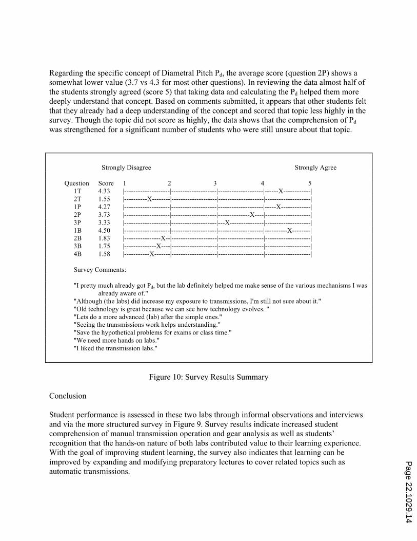
Regarding the specific concept of Diametral Pitch Pd, the average score (question 2P) shows a somewhat lower value (3.7 vs 4.3 for most other questions). In reviewing the data almost half of the students strongly agreed (score 5) that taking data and calculating the Pd helped them more deeply understand that concept. Based on comments submitted, it appears that other students felt that they already had a deep understanding of the concept and scored that topic less highly in the survey. Though the topic did not score as highly, the data shows that the comprehension of Pd was strengthened for a significant number of students who were still unsure about that topic. Strongly Disagree Strongly Agree Question Score 1 2 3 4 5 1T 4.33 |--------------------|--------------------|--------------------|------X------------| 2T 1.55 |----------X--------|--------------------|--------------------|--------------------| 1P 4.27 |--------------------|--------------------|--------------------|-----X-------------| 2P 3.73 |--------------------|--------------------|--------------X----|--------------------| 3P 3.33 |--------------------|--------------------|---X---------------|--------------------| 1B 4.50 |--------------------|--------------------|--------------------|----------X--------| 2B 1.83 |----------------X--|--------------------|--------------------|--------------------| 3B 1.75 |--------------X----|--------------------|--------------------|--------------------| 4B 1.58 |-----------X-------|--------------------|--------------------|--------------------| Survey Comments: "I pretty much already got Pd, but the lab definitely helped me make sense of the various mechanisms I was already aware of." "Although (the labs) did increase my exposure to transmissions, I'm still not sure about it." "Old technology is great because we can see how technology evolves. " "Lets do a more advanced (lab) after the simple ones." "Seeing the transmissions work helps understanding." "Save the hypothetical problems for exams or class time." "We need more hands on labs." "I liked the transmission labs."
Figure 10: Survey Results Summary
Conclusion Student performance is assessed in these two labs through informal observations and interviews and via the more structured survey in Figure 9. Survey results indicate increased student comprehension of manual transmission operation and gear analysis as well as students’ recognition that the hands-on nature of both labs contributed value to their learning experience. With the goal of improving student learning, the survey also indicates that learning can be improved by expanding and modifying preparatory lectures to cover related topics such as automatic transmissions.
Page 22.1029.14
These two labs give context to many of the mechanisms that are studied in a Mechanical Design course. Though all aspects of modern transmissions are not addressed, enough of the basic mechanical concepts are integrated that a student can adapt what they have learned to analyze most mechanical transmission designs. While textbooks may present these topics effectively, and video animations help with comprehension, the analysis of a simplified physical example in hands-on labs gives students a deeper understanding of basic mechanical principles. Student surveys indicate that these hands on learning experiences work for students. References: 1. Wikipedia. "List of gear nomenclature" http://en.wikipedia.org/wiki/List_of_gear_nomenclature , 2011 2. Mott, Robert L. "Kinematics of Gears", Machine Elements in Mechanical Design, 4th edition, Pearson Education Inc, Upper Saddle River, NJ , pages 363-490, 2004 3. Model T Central. "Transmission" http://www.modeltcentral.com/transmission_animation.html , 2011 4. Page, Victor W. The Model T Ford Car; Its Construction, Operation, and Repair Norman W. Henley Publishing Company, New York, NY, page 263 (Plate 89), 1917 5. EngineeringAutomotive.com. "Gearbox operation", http://www.engineeringautomotive.com/videos/ automotive_training_video_details-id-178.html , 2011 6. EngineeringAutomotive.com. "Automatic Transmission Principles", http://www.engineeringautomotive.com/videos/ automotive_training_video_details-id-118.html , 2011
Page 22.1029.15
Appendix 1: Summary of MET 418 / 419 Mechanical Design Lab Activities at CWU To give context to the transmission labs outlined in this paper, the following list of lab activities for the Mechanical Design courses at CWU has been included. The labs continue to evolve each year. Lab topics for the 2010-11 academic year courses are outlined below: MET 418 Mechanical Design 1 Lab 1: Free Body Diagram Review & Workshop Lab 2: Group Design Project (Cooperative Design): Introduction & Requirements Development Groups work cooperatively on different modules of one larger project (Electrathon Racer) Front Steering/Suspension Module, Center Chassis Structure Module, Rear Drive/Suspension Module, and Integration & Management Module Lab 3: Electrathon Project: Stress Calculaton and Material Spec for Electrathon Part Lab 4: Electrathon Project: Morh's Circle Analysis for Electrathon Part Lab 5: Electrathon Project: Failure Analysis on Electrathon Part Lab 6: Electrathon Project: Column Analysis on Electrathon Part Lab 7: Electrathon Project: Chain & Belt Drive Calculations/ Specs for Electrathon Drive Lab 8: Gear Lab: Design & Manufacture spur gear on a manually operated horizontal mill MET 419 Mechanical Design 2 Lab 1: Three Speed Transmission Analysis Lab (Described in this paper) Lab 2: Planetary Transmission Analysis Lab (Model T) (Described in this paper) Lab 3: Shaft Load Analysis Lab: Analysis of torsion and bending in a gear driven shaft with V- belt and chain driven loads Lab 4: Bearing Selection / Shaft Design Lab: Based Lab 3 loading, shaft diameter is selected, a ball bearing is specified, and a shop-ready manufacturing drawing is produced Lab 5: Design Brainstorming Exercise; Develop alternatives, use decision matrix Lab 6: Group Design Project (Competitive Design): Concept & Requirements; Each group prepares their design for a human powered electric generator. Most practical design to be built in time for Earth Day display for iPod & cell phone charge station, video projector/movie Lab 7: Group Design Project: Progress Report Lab 8: Group Design Project: Design Project Presentations
Page 22.1029.16
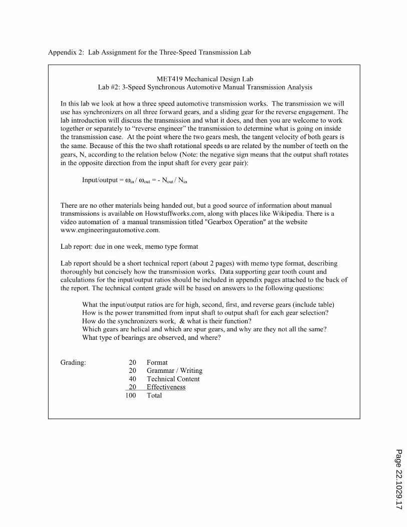
Appendix 2: Lab Assignment for the Three-Speed Transmission Lab
Page 22.1029.17
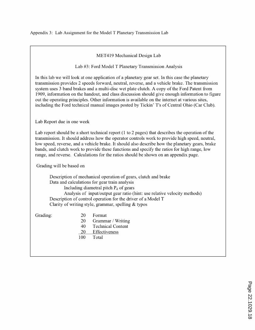
Appendix 3: Lab Assignment for the Model T Planetary Transmission Lab
Page 22.1029.18
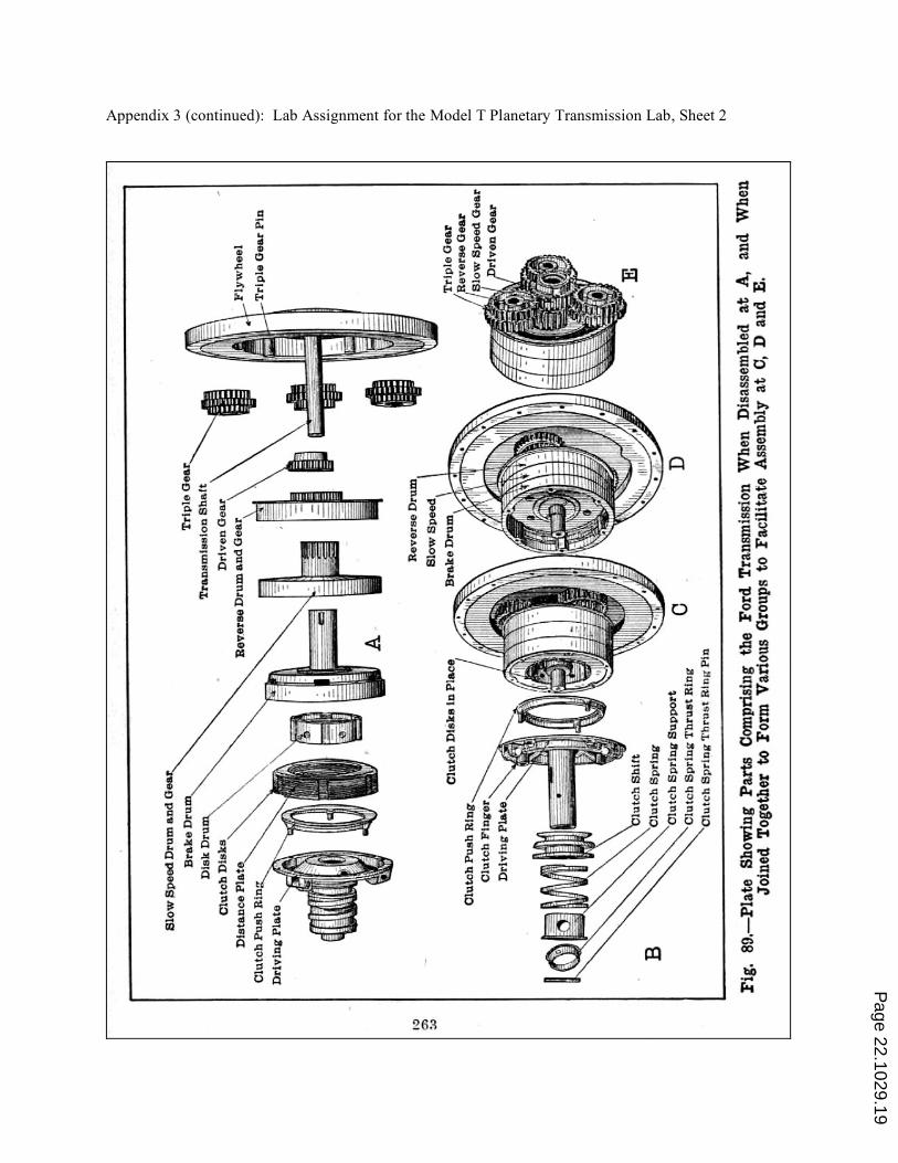
Appendix 3 (continued): Lab Assignment for the Model T Planetary Transmission Lab, Sheet 2
Page 22.1029.19
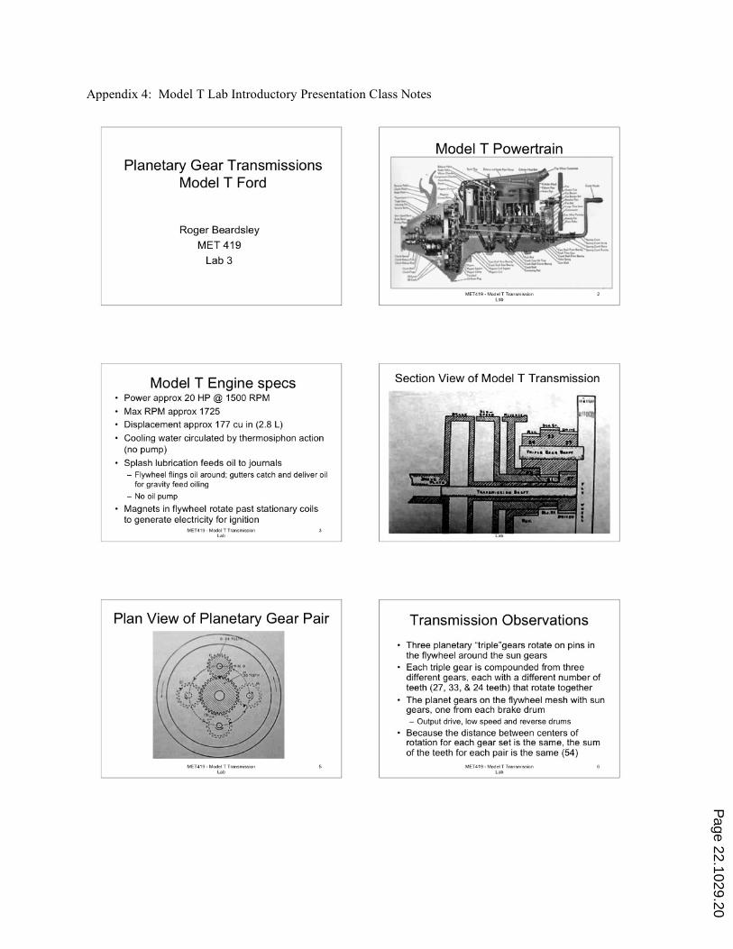
Appendix 4: Model T Lab Introductory Presentation Class Notes
Page 22.1029.20
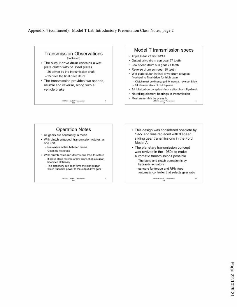
Appendix 4 (continued): Model T Lab Introductory Presentation Class Notes, page 2
Page 22.1029.21
Related Documents