1 1. INTRODUCTION 1.1 BACKGROUND In the continuing quest for improved performance, which may be specified by various criteria including less weight, more strength and lower cost, currently used materials frequently reach the limit of their usefulness. Thus material scientists, engineers and scientists are always striving to produce either improved traditional materials or completely new materials. Composites are an example of the latter category. Within last forty to fifty years, there has been a rapid increase in the production of synthetic composites, those incorporating fine fibers in various plastics (polymers) dominating the market. With the increasing global energy crisis and ecological risks, scientists all over the world are shifting their attention towards alternative solution to synthetic fiber. Since 1990s, natural fiber composites are emerging as realistic alternative to glass-reinforced composites in many applications. Natural fiber composites are claimed to offer environmental advantages such as reduced dependence on non-renewable energy/material sources, lower pollutant emissions, lower green-house gas emissions, enhanced energy recovery and end of life biodegradability of components. Such superior environmental performances are important driver of increased future use of natural fiber composite. India endowed with an abundant availability of natural fiber such as Jute, Coir, Sisal, Pineapple, Ramie, Bamboo, Banana etc. has focused on the development of natural fiber composites primarily to explore value-added application avenues. Such natural fiber composites are well suited as wood substitutes in the housing and construction sector. The development of natural fiber composites in India is based on two pronged strategy of preventing depletion of forest resources as well as ensuring good economic returns for the cultivation of natural fibers. The developments in composite material after meeting the challenges of aerospace sector have cascaded down for catering to domestic and industrial applications. Composites, the wonder material with light-weight; high strength-to-weight ratio and

Machenical
Dec 09, 2015
final year report
Welcome message from author
This document is posted to help you gain knowledge. Please leave a comment to let me know what you think about it! Share it to your friends and learn new things together.
Transcript

1
1. INTRODUCTION
1.1 BACKGROUND
In the continuing quest for improved performance, which may be specified by various
criteria including less weight, more strength and lower cost, currently used materials
frequently reach the limit of their usefulness. Thus material scientists, engineers and
scientists are always striving to produce either improved traditional materials or completely
new materials. Composites are an example of the latter category.
Within last forty to fifty years, there has been a rapid increase in the production of
synthetic composites, those incorporating fine fibers in various plastics (polymers)
dominating the market. With the increasing global energy crisis and ecological risks,
scientists all over the world are shifting their attention towards alternative solution to
synthetic fiber. Since 1990s, natural fiber composites are emerging as realistic alternative
to glass-reinforced composites in many applications.
Natural fiber composites are claimed to offer environmental advantages such as
reduced dependence on non-renewable energy/material sources, lower pollutant emissions,
lower green-house gas emissions, enhanced energy recovery and end of life
biodegradability of components. Such superior environmental performances are important
driver of increased future use of natural fiber composite.
India endowed with an abundant availability of natural fiber such as Jute, Coir, Sisal,
Pineapple, Ramie, Bamboo, Banana etc. has focused on the development of natural fiber
composites primarily to explore value-added application avenues. Such natural fiber
composites are well suited as wood substitutes in the housing and construction sector.
The development of natural fiber composites in India is based on two pronged strategy
of preventing depletion of forest resources as well as ensuring good economic returns for
the cultivation of natural fibers.
The developments in composite material after meeting the challenges of aerospace
sector have cascaded down for catering to domestic and industrial applications.
Composites, the wonder material with light-weight; high strength-to-weight ratio and

2
stiffness properties have come a long way in replacing the conventional materials like
metals, wood etc. The material scientists all over the world focused their attention on
natural composites reinforced with Jute, Sisal, Coir, Pineapple etc. primarily to cut down
the cost of raw materials.
1.2 WHY A COMPOSITE?
Over the last thirty years composite materials, plastics and ceramics have been the
dominant emerging materials. The volume and number of applications of composite
materials have grown steadily, penetrating and conquering new markets relentlessly.
Modern composite materials constitute a significant proportion of the engineered materials
market ranging from everyday products to sophisticated niche applications.
While composites have already proven their worth as weight-saving materials, the current
challenge is to make them cost effective. The efforts to produce economically attractive
composite components have resulted in several innovative manufacturing techniques
currently being used in the composites industry. It is obvious, especially for composites,
that the improvement in manufacturing technology alone is not enough to overcome the
cost hurdle.
It is essential that there be an integrated effort in design, material, process, tooling, quality
assurance, manufacturing, and even program management for composites to become
competitive with metals.
The composites industry has begun to recognize that the commercial applications of
composites promise to offer much larger business opportunities than the aerospace sector
due to the sheer size of transportation industry. Thus the shift of composite applications
from aircraft to other commercial uses has become prominent in recent years.
Increasingly enabled by the introduction of newer polymer resin matrix materials and high
performance reinforcement fibers of glass, carbon and aramid, the penetration of these

3
advanced materials has witnessed a steady expansion in uses and volume. The increased
volume has resulted in an expected reduction in costs.
Further, the need of composite for lighter construction materials and more seismic resistant
structures has placed high emphasis on the use of new and advanced materials that not only
decreases dead weight but also absorbs the shock & vibration through tailored
microstructures. Composites are now extensively being used for rehabilitation
strengthening of pre-existing structures that have to be retrofitted to make them seismic
resistant, or to repair damage caused by seismic activity.
Unlike conventional materials (e.g., steel), the properties of the composite material can be
designed considering the structural aspects. The design of a structural component using
composites involves both material and structural design. Composite properties (e.g.
stiffness, thermal expansion etc.) can be varied continuously over a broad range of values
under the control of the designer. Careful selection of reinforcement type enables finished
product characteristics to be tailored to almost any specific engineering requirement.
1.3 Types of Composite Materials
4
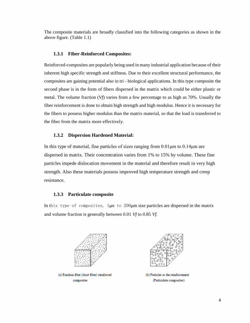
The composite materials are broadly classified into the following categories as shown in the
above figure. (Table 1.1)
1.3.1 Fiber-Reinforced Composites:
Reinforced-composites are popularly being used in many industrial application because of their
inherent high specific strength and stiffness. Due to their excellent structural performance, the
composites are gaining potential also in tri - biological applications. In this type composite the
second phase is in the form of fibers dispersed in the matrix which could be either plastic or
metal. The volume fraction (Vf) varies from a few percentage to as high as 70%. Usually the
fiber reinforcement is done to obtain high strength and high modulus. Hence it is necessary for
the fibers to possess higher modulus than the matrix material, so that the load is transferred to
the fiber from the matrix more effectively.
1.3.2 Dispersion Hardened Material:
In this type of material, fine particles of sizes ranging from 0.01μm to 0.14μm are
dispersed in matrix. Their concentration varies from 1% to 15% by volume. These fine
particles impede dislocation movement in the material and therefore result in very high
strength. Also these materials possess improved high temperature strength and creep
resistance.
1.3.3 Particulate composite
In this type of composites, 1μm to 200μm size particles are dispersed in the matrix
and volume fraction is generally between 0.01 Vf to 0.85 Vf.

5
1.4 Natural Fibers Composite: Initiative in Product Development
Now-a-days, research and engineering interest have been shifting from traditional
Synthetic fiber composite to lignocellulosic natural fiber composite due to their advantages
like high strength to weight ratio, non-carcinogenic and bio-degradability. Besides the
availability of natural fibers and easy of manufacturing have tempted researchers to try
locally available inexpensive fiber and to study their feasibility of reinforcement purpose
and to what extent they satisfy the required specifications of good reinforced polymer
composite for different applications.
With low cost and high specific mechanical properties, natural fiber represents a good
renewable and biodegradable alternative to the most common synthetic reinforcement, i.e.
glass fiber. The term “natural fiber” covers a broad range of vegetable, animal and mineral
fibers.

6
However in the composite industry, it is usually refers to wood fiber and agro based
bast, leaf, seed, and stem fibers. These fibers often contribute greatly to the structural
performance of plant and, when used in plastic composites, can provide significant
reinforcement. Despite the interest and environmental appeal of natural fibers, their use is
limited to non-bearing applications due to their lower strength compared with synthetic fiber
reinforced polymer composite.
Fig. 1.2 Overview of Natural Fiber
The stiffness and strength shortcomings of bio composites can be overcome by
structural configurations and better arrangement in a sense of placing the fibers in specific
locations for highest strength performance. Accordingly extensive studies on preparation
and properties of polymer matrix composite (PMC) replacing the synthetic fiber with natural
fiber like Jute, Sisal, Pineapple, Bamboo and Kenaf were carried out. These plant fibers
have many advantages over glass fiber or carbon fiber like renewable, environmental
friendly, low cost, lightweight, high specific mechanical performance. Increased technical
innovation, identification of new applications, continuing political and environmental

7
pressure and government investments in new methods for fiber harvesting and processing
are leading to projections of continued growth in the use of natural fibers in composites,
with expectation of reaching 100,000 tons per annum by 2010.
Fig 1.3 Classification of natural fiber that can be used as reinforcements in polymers
The easy availability of natural fibers and manufacturing have motivated researchers
worldwide recently to try locally available inexpensive fibers and to study their feasibility
of reinforcement purposes and to what extent they satisfy the required specifications of good
reinforced polymer composite for tribological applications. There are many natural
resources which India has in abundance. Most of it comes from the forest and agriculture.
However in most cases residues from traditional crops such as rice husk or sugarcane
bagasse or from the usual processing operations of timber industries do not meet the
requisites of being long fibers. This biomass left over are abundant, and their use as a
particulate reinforcement in resin matrix composite is strongly considered as a future
possibility.
8
1.5 What is Fly Ash?
Fly ash is a coal combustion byproduct, which accumulates due to electrostatic precipitation
of the flue gases in thermal power plant. The spherical shaped materials blown out from the
furnace during combustion of coal in thermal power stations make up 75% of ash generated. The
spherules when empty are called cenospheres and when filled up with smaller spheres are known as
plerospheres. The cenospheres comprise of 0.5–1.0 weight percentage of the fly ash individual
particles are chemically fairly homogeneous, but the pronounced compositional variation exists
among particles with similar physical and structural attribute. Cenospheres are compressed of nearly
stoichiometric mullite (3Al2O3·2SiO2) needles bonded by aluminosilicate glass of similar
composition that offers excellent thermal, elastic, and mechanical characteristics for use in
thermostructural applications. Elemental map study through energy filtered TEM shows the
aluminosilicate-based and iron oxide based-nanoparticles are present in the fly ash. Unburned
organic matter during combustion of coal leaves carbon in three different forms in the fly ash. Fly
ash contains toxic elements like Co, Pb, Ni, Cd, Cu, Fe, and Zn in trace. Particle filled polymer
composites have become attractive because of their wide applications and low cost. Polymers such
as Nylon 6, Natural Rubber, Styrene Butadiene Rubber, Epoxy, Poly styrene, Poly Aniline, and
HDPE, incorporating inorganic mineral fillers into plastic resin, improve various physical properties
of the materials such as mechanical strength, modulus, and heat distortion temperature as
compared to neat resin components. In general, the mechanical properties of particulate filled
composites depend strongly on size, shape, and distribution of filler particles in the matrix and
good adhesion at the interface surface.
The demand for the light-weight materials such as for surfaces of ships had led to the
development of fly –ash based thermosetting resins.
1.5.1 Fly Ash as a Filler Material
When coal is burnt in thermal power plant the ash is carried forward in flue gases as fused
particles, which solidifies as a spherical particle. Most of these spherical particles have a
gas bubble at the center. The constituents of fly ash particles as obtained from coal in are
silica (59.5%), Alumina (20.3%), FeO /Fe2O3 (6.5%), remaining being FeO, MgO and

9
unburnt coal etc. Fly ash depending upon the source of coal, contain different proportions
of silica, alumina, oxides of iron, calcium, magnesium etc. along with elements like carbon,
Ti, Mg, etc. So the fly ash has properties combined of spherical particles and that of metals
and metal oxides. Filler materials are generally the inert materials which are used in
composite materials to reduce material costs, to improve mechanical properties to some
extent and in some cases to improve processability.
1.6 Why Double reinforced composite?
Use of PMCs imposes some real constraints on structural applications due to
comparatively weak matrix, imbibe water, and other liquids to a significant degree cannot
perform well at moderate elevated temperature, internal cracking is so common, higher
thermal expansion, maintaining good adhesion is difficult, chemical and thermal
degradations in service often occurs.
The addition of short Sugarcane fibers matrix allows stress transfer across the matrix
crack to improve toughness. Therefore, in the present work, the addition of fly ash to the
epoxy resin with the additional reinforcement of sugarcane fibers was carried out to
fabricate composite. These composites were characterized and it was seen that the
additional reinforcement with the fly ash as filler could improve the strength of the
composites as compared to single reinforcement.
In fiber epoxy composites the addition of fly ash led to a reduction of the density and
increase in modulus of composites. At present, epoxy resins are widely used in various
engineering and structural applications such as electrical industries, and commercial and
military aircrafts industries.
In order to improve their processing and product performances, and to reduce cost,
various fillers are introduced into the resins during processing

10
2. LITERATURE
2.1 Structure of Plant Fiber
Natural plant fibers are constituents of cellulose fibers, consisting of helically wound
cellulose micro fibrils, bound together by an amorphous lignin matrix. Lignin keeps
the water in fibers; acts as a protection against biological attack and as a stiffener to
give stem its resistance against gravity forces and wind. Hemicellulose found in the
natural fibers is believed to be a compatibilizer between cellulose and lignin. The cell
wall in a fiber (Figure 2.1) is not a homogenous membrane.
Fig 2.1 Structure of an elementary plant fiber (cell)
Each fiber has a complex, layered structure consisting of a thin primary wall which is the
first layer deposited during cell growth encircling a secondary wall. The secondary wall is
made up of three layers and the thick middle layer determines the mechanical properties of

11
the fiber. The middle layer consists of a series of helically wound cellular micro-fibrils
formed from long chain cellulose molecules.
The angle between the fiber axis and the micro-fibrils is called the microfibrillar angle. The
characteristic value of microfibrillar angle varies from one fiber to another.
These micro-fibrils have typically a diameter of about 10-30 nm and are made up of 30-
100 cellulose molecules in extended chain conformation and provide mechanical strength
to the fiber.
2.2 Matrix Material
Many materials when they are in fibrous form exhibit very good strength properties but to
achieve these properties the fiber should be bonded by a suitable matrix. The matrix isolates
the fibers from one another in order to prevent abrasion and formation of new surface flaws
and acts as a bridge to hold the fibers in place. A good matrix should possess ability to
deform easily under applied load, transfer the load on to the fibers and evenly distribute
stress concentration.
A study of the nature of bonding forces in laminates indicates that upon initial
loading there is a tendency for the adhesive bond between them account for the high
strength properties of the of the laminates.
The polymer matrix binds the fibers together so as to transfer the load to and
between them and protect them from environments and handling. Polymer or resin system
used to manufacture advanced polymer matrix composites (PMCs) are of two basic types,
thermosets and thermoplastics (including bio-derived ones).
2.2.1 Thermosets
Much of the early work used thermosetting resins as matrix material for composite
production. Products like tufnol which is made from cotton fibres and epoxy resin, have
been available for some time, having good stiffness and strength. In the last few years there
has been renewed interest in these products for use in automotive applications. To achieve
reinforcing effects in composites it is necessary to have good adhesion between the fibres
12
and resins. Epoxy and phenolic thermosetting resins are known to be able to form covalent
cross-links with plant cell walls via -OH groups. Composite manufacture can be achieved
using low viscosity epoxy and phenolic resins that cure at room temperature. In addition
epoxy resin does not produce volatile products during curing which is most desirable in
production of void free composites. Therefore, although epoxy resins are relatively more
expensive than polyester, they have potential for the development of high added value plant
fiber composites, where long fibres at a high content are required.
The functional group in epoxy resins is called the oxirane, a three-membered
strained ring containing oxygen. Epoxy resins, depending on their backbone structure, may
be low or high viscosity liquids or solids. In low viscosity resin, it is possible to achieve a
good wetting of fibres by the resin without using high temperature or pressure. The
impregnation of fibres with high viscosity resins is done by using high temperature and
pressure.
A wide range of starting materials can be used for the preparation of epoxy resins
thereby providing a variety of resins with controllable high performance characteristics.
These resins generally are prepared by reacting to a poly functional amine or phenol with
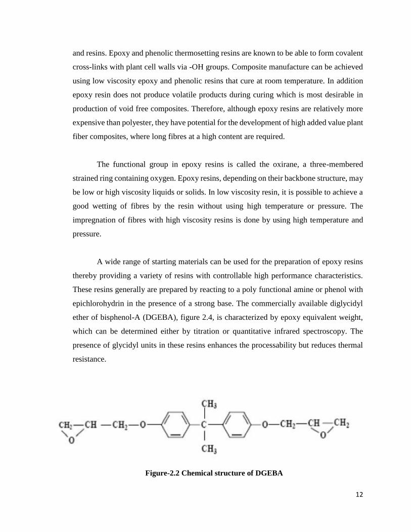
epichlorohydrin in the presence of a strong base. The commercially available diglycidyl
ether of bisphenol-A (DGEBA), figure 2.4, is characterized by epoxy equivalent weight,
which can be determined either by titration or quantitative infrared spectroscopy. The
presence of glycidyl units in these resins enhances the processability but reduces thermal
resistance.
Figure-2.2 Chemical structure of DGEBA

13
The most widely used curing agents for epoxy resins are primary and secondary
amines. The overall reaction rate of an amine with an epoxide is influenced by the steric
hindrance and the electron withdrawing or electron donating groups present in the amine.
During curing, epoxy resins can undergo three basic reactions:
1. Epoxy groups are rearranged and form direct linkages between themselves.
2. Aromatic and aliphatic -OHs link up to the epoxy groups.
3. Cross-linking takes place with the curing agent through various radical groups.
The advantages of epoxy resins are low polymerization shrinkages unlike polyesters during
cure, good mechanical strength, excellent resistance to chemicals and solvents and
excellent adhesion to fibres. The epoxy molecule also contains two ring groups at its centre,
which are able to absorb both mechanical and thermal stresses better than linear groups,
giving epoxy resin very good stiffness, toughness and heat resistance.
The primary disadvantages of the epoxy resins are that they require long curing
times and in general, their mould release characteristics are poor. The epoxy resins are
characterized by their high adhesive strengths. This property is attributed to the polarity of
aliphatic -OH groups and ether groups that exist in both the initial resin and cured system.
The polarity associated with these groups promotes electromagnetic bonding forces
between epoxy molecules and the polar fibers.
2.2.2 Bio-derived Thermoplastic Matrices
Cellulose fibers (e.g. hemp, flax, jute) are widely used with conventional
thermoplastic polymers (e.g. PP, PE) as reinforcement in composite production to improve
mechanical properties. In fact, the history of composites from renewable resources is far
longer than conventional polymers. The study and utilization of natural polymers is an
ancient science. Typical examples, such as paper, silk, skin and bone arts can easily be
found in museum around the world. In the biblical Book of Exodus, Moses’s mother built
the ark from rushes, pitch and slime - a kind of fibre reinforced composite, according to
the current classification of material.

14
During the opium war more than 1000 years ago, the Chinese built their castles to
defend against invaders using a kind of mineral particle reinforced composite made
from gluten rice, sugar, calcium carbonate and sand. However, the availability of
petroleum at a lower cost and the bio-chemical inertness of petroleum based
products have proven disastrous for the market of natural polymers. It is only about
last two decades when the significance of eco-friendly materials has been realized.
Now polymers from renewable resources have started drawing an increasing
amount of attention. The two main reasons for that are environmental concerns, and
the realization that the petroleum resources are limited.
Generally, polymers from renewable resources can be classified into three groups:
1. Natural polymers such as starch, protein, and cellulose
2. Synthetic polymers from natural monomers, such as PLA
3. Polymers from microbial fermentation, such as polyhydroxy butyrate
(PHB).
Like numerous other petroleum based polymers, many properties of
polymers from renewable resources can be improved through composite
production.
The development of synthetic polymers like PLA using monomers from natural
resources has been a driving force for the development of biodegradable polymers from
renewable resources. Therefore, in today’s world PLA is the most promising among
bioderivable polymers. PLA can be processed (e.g. compression moulding, pultrusion,
extrusion and injection moulding) like petroleum based polyolefins and its mechanical
property is better than the widely used polymer PP. On degradation PL does not emit any
carbon dioxide to the environment like other biodegradable materials from renewable
resources.
The degradation occurs by hydrolysis to lactic acid, which is metabolized by micro-
organisms to water and carbon dioxide. If PLA is comprised together with other biomass,
the biodegradation occurs within a couple of weeks and the material can fully disappear

15
within a month. Chemically, it is linear aliphatic polyester of lactic acid which can be
obtained by fermentation of renewable agricultural materials like corn, sugarcane and sugar
beets. Lactic acid is converted to a cyclic lactide dimer which is then polymerized to PLA
through a ring opening reaction.
The major applications of PLA products are in household wastes as plastic bags,
barriers for sanitary products and diapers, planting, and disposable cups and plates.
However, a number of authors reported the possibilities of developing fully bio-degradable
composite products by using biodegradable polymers as matrix and natural fibres as
reinforcements. Keller et al reported that PLA should produce fiber reinforced composites
with high mechanical properties for light weight construction materials. Oksman et al
observed that PLA had good potential as a polymer matrix in flax fibre reinforcement for
composites production.
They reported that the composite strength produced with PLA/flax was about 50%
better than that of PP/flax composites. Due to the increasing commercial interest for natural
fiber reinforced polymer composites for use in automotive applications and building
constructions as well as demands for environmentally friendly materials, the development
of fully biodegradable composites for many applications could be an interesting area of
research.
2.3 Natural Fiber Reinforced Polymer Composites
Polymer materials by themselves have found extensive use in noncritical products.
Such products are used in advanced engineering applications when reinforced with stronger
materials. Therefore fiber reinforced composites comprised of thermoplastics and natural
fibers are a well research area at present for their high specific strength and modulus. The
advantages of natural lignocellulosic fibers over traditional reinforcing materials such as
carbon, glass fibers, talc and mica are low cost, acceptable specific strength properties, low
density, non abrasivity, good thermal properties, enhanced energy recovery and
biodegradability. The use of natural fibers in plastic matrix includes many benefits such as
low volumetric cost, increase of heat deflection temperature, increase of stiffness of
thermoplastics and improvement of wood surface appearance. So natural fibers have

16
achieved applications in making several complex structures such as tubes, interior
paneling, sandwich plates, decking, furniture parts, sports usages etc.
One of the largest areas of recent growth in natural fiber plastic composites in world-wide
is the automotive industry, where natural fibers are advantageously used as a result of their
low density and increasing environmental pressures. They are also used in electrical and
electronic application for their nonconductive and excellent insulation against heat and
noise. Natural fibers composites found application where load bearing capacity and
dimensional stability under moist and high thermal conditions are of second order
importance.
For example, flax fiber reinforced polyolefins are extensively used today in the automotive
industry, but the fiber acts mainly as filler material in non-structural interior panels. Natural
fiber composites used for structural purposes do exist, but then usually with synthetic
thermo-set matrices which of course limit the environmental benefits. Natural fibers like
sisal, jute, coir, oil palm, bamboo, wheat and flax straw, waste silk and banana have proved
to be good and effective reinforcement in thermoset and thermoplastic matrices due to their
high aspect ratio and high specific strength- and stiffness.
Apart from good specific mechanical properties and positive environmental impact, other
benefits from using natural fibers worth mentioning are low cost, friendly processing, low
tool wear, no skin irritation and good thermal and acoustic insulating properties.
A complete biodegradable system may be obtained if the matrix material also comes from
a renewable resource. Examples of such materials are lignophenolics, starch and polylactic
acid (PLA). Some of these systems show encouraging results. For example Oksman et al
have reported that flax fiber composites with PLA matrix can compete with and even
outperform flax/polypropylene composites in terms of mechanical properties.
In a recent study it was found that composites of poly-L-lactide acid (PLLA) reinforced by
flax fibers can show specific tensile modulus equivalent to that of glass/polyester short
fiber composites. The specific strength of flax/PLLA composites was lower than that of
glass/polyester, but higher than that of flax/polyester.

17
The limited use of natural fiber composites is also connected with some other major
disadvantages still associated with these materials. The fibers generally show low ability
to adhere to common non-polar matrix materials for efficient stress transfer. Furthermore,
the fibers inherent hydrophilic nature makes them susceptible to water uptake in moist
conditions. Natural fiber composites tend to swell considerably with water uptake and as a
consequence mechanical properties, such as stiffness and strength, are negatively
influenced. However, the natural fiber is not inert. The fiber-matrix adhesion may be
improved and the fiber swelling reduced by means of chemical, enzymatic or mechanical
modifications.
There are many application of natural fiber composite in everyday life. For example, jute
is a common reinforcement for composites in India. Jute fiber with polyester resins is used
in buildings, elevators, pipes, and panels. Natural fiber composites can also be very cost
effective material for application in building and construction areas (e.g. walls, ceiling,
partition, window and door frames), storage devices (e.g. bio-gas container, post boxes,
etc.), furniture (e.g. chair, table, tools, etc.), electronic devices (outer casting of mobile
phones), automobile and railway coach interior parts (inner fenders and bumpers), toys and
other miscellaneous applications (helmets, suitcases).
During the last few years, a series of works have been done to replace the conventional
synthetic fiber with natural fiber composites. For instant, hemp, sisal, jute, cotton, flax and
broom are the most commonly used fibers to reinforce polymers like polyolefins,
polystyrene, and epoxy resins. In addition, fibers like sisal, jute, coir, oil palm, bamboo,
wheat and flax straw, waste silk and banana have proved to be good and effective
reinforcement in the thermoset and thermoplastic matrices.
Nevertheless, certain aspects of natural fiber reinforced composite behaviour still poorly
understood such as their visco elastic, visco plastic or time-dependent behavior due to creep
and fatigue loadings, interfacial adhesion, and tribological properties. Little information
concerning the tribological performance of natural fiber reinforced composite material has
been reported. In this context, long plant fibres, like hemp, flax, and bamboo have

18
considerable potential in the manufacture of composite materials. Likewise, bagasse fibers
may also have considerable potential as reinforcement for polymer and may provide
advantages when used as a substitute for conventional synthetic glass fiber.
After reviewing the exiting literature available on the natural fiber composite efforts are
put to understand the basic needs of the growing composite industry. The conclusions
drawn from this is that, the success of combining vegetable natural fibers with polymer
matrices results in the improvement of mechanical properties of the composite compared
with the matrix material.
These fillers are cheap and non - toxic can be obtain from renewable source and are easily
recyclable. Moreover despite of their low strength, they can lead to composites with high
specific strength because of their low density. Thus the priority of this work is to prepare
polymer matrix composites (PMCs) using bagasse fiber as reinforcement material. To
improve the interfacial strength between the fiber and the matrix, the surface modification
of the fiber has to be done by chemical treatment. The composite will then be subjected to
different weathering condition like steam, saline and subzero condition. The potential of
bagasse fiber for tribological application has to be investigated through performing
different tribological tests like abrasive wear test, two body abrasion test and solid particle
erosion test as per ASTM standard. The fiber characterization will be done by Fourier
Transfer Infrared (FTIR) spectroscopy before and after the chemical treatment. The
flexural strength of the composite will be evaluated along with other mechanical tests.

19
3. OBJECTIVES
3.1 To Develop A Composite Material With Improved Wear Property
And Hardness By Addition Of Fly Ash And Natural Fibers
The project started with various compositions of Fly Ash, Fiber and Epoxy. It was
required to test and decide upon the composition which will give best wear and
compression properties.
It was decided to make two sets of samples, which will have same amount of Epoxy but
different composition of Fly Ash by weight. Through this we were able to compare the
effect of increase in both fly ash content and fiber over the wear properties.
3.2 To Find a Suitable Substitute for Synthetic Fiber by Using Natural
Fiber
With low cost and high specific mechanical properties, natural fiber represents a
good renewable and biodegradable alternative to the most common synthetic
reinforcement, i.e. glass fiber. The Natural Fibers are easy to obtain, and are not
harmful to the environment.
One of the reason, synthetic fibers are preferred over Natural Fibers is that they have
high strength, this issue was resolved by the addition of Fly Ash.
Hence, it was expected that the composite formed will have high strength and good
mechanical properties which are comparable to synthetic composites.

20
3.3 To Make Optimum Use of Industrial Waste in the Form of Fly Ash
by Using it as a Filler Material in Composite
One reason to use Fly Ash was to help with the mechanical properties. The other
main reason was to utilize it as Industrial Waste, and use it as a Filler Material
Composites thereby also reducing the amount of Matrix Material used in Composite.
With the increase in Fly Ash the holding capacity of Epoxy increased, which helped
in holding the Fiber.
3.4 To Develop a Suitable Application for The Composite Material
Developed
After obtaining the Optimum Composition of Fly Ash, Fiber and Epoxy it is required
to use the material obtained in a suitable application. This was supposed to be
decided according the results obtained in the various tests conducted throughout the
Project.
A suitable application of the material, to be used in everyday application.

21
4. METHODOLOGY
For Preparation of Composite the following materials were used:
1. Bagasse Fiber
2. Fly Ash
3. Epoxy
4. Hardener
4.1 Preparation of Bagasse Fiber
The Sugarcane Stalk is composed of an outer rind and inner pith. The upper layers of
bagasse consist of a hard fibrous substance called rind while inside is soft material called pith. The
pith contains small fibers and the majority of the sucrose, while the rind contains longer and finer
fiber, arranged randomly throughout the stem and bound together by lignin and hemicelluloses. It
is reported that fibers are often located adjacent to the inner wall of the rind particle. For the present
investigation, fresh bagasse fibers were collected from local Juice Venders located in Manipal.
4.1.1 Treatment of Fiber
These fibers were then spread on a water proof sheet and kept under sunlight for a day to
reduce the moisture content. Then these fibers were then shredded using the Champ Agro Machine
in Composite Lab of Manipal Institute of Technology.
After shredding, these were then treated by NaOH, an Alkali reaction takes place, as shown:
Bagasse-OH + NaOH Bagasse-O-Na+ + H2O
The NaOH reacts with hydroxyl groups of the cementing material HemiCellulose, and it
brings on the destruction of the cellular structure and thereby the fibers split into Filaments. These
fibers were kept in 4% NaOH solution, then washed thoroughly using distilled water in order to

22
remove all the enzymes present on the fiber. Then was kept to dry under sunlight for further 12
hours.
After approximately two days, the long bagasse fibers (rind proportion only) were shortened into
a length of approximately 10mm and width of 1mm with a pair of scissor. Due to low moisture of
the bagasse samples, no fungi grew during the storage.
4.2 Epoxy Resin and Hardener
Epoxy resins are relatively low molecular weight pre-polymers capable of being
processed under a variety of conditions. Two important advantages of these over unsaturated
polyester resins are: first, they can be partially cured and stored in that state, and second they
exhibit low shrinkage during cure.
However, the viscosity of conventional epoxy resins is higher and they are more expensive
compared to polyester resins. The cured resins have high chemical, corrosion resistance, good
mechanical and thermal properties, outstanding adhesion to a variety of substrates, and good and
electrical properties.
Approximately 45% of the total amount of epoxy resins produced is used in protective coatings
while the remaining is used in structural applications such as laminates and composites, tooling,
moulding, casting, construction, adhesives, etc. The type of epoxy resin used in the present
investigation is Epoxy L-12 which chemically belongs to epoxide family.
Both Epoxy and Hardener were supplied by Atul Polymer Ltd, Gujarat.
4.3 Preparation of Composite Laminates
A plastic frustum shaped mold (fig 4.1) was used for casting the composite sample. The first group
of samples was manufactured with 1.5g of Fiber, 50g of Epoxy and 20, 30, 40, 50 and 60 % by
weight of fly ash. (Table 4.1)

23
Usual hand lay-up technique was used for preparation of the samples. A calculated amount of
hardener (ratio of 10:1 by weight, epoxy to hardener) was thoroughly mixed in a glass jar and
placed to settle. This procedure was performed for 5 minutes initially.
Fig. 4.1 Mold Used
After mixing the contents properly in the glass jar, they were poured into the mold. Care was taken
to avoid formation of air bubbles. A plastic sheet was placed on the contents and pressure was
applied from the top and the mold was allowed to cure at room temperature for 24 hours.
During Application of pressure some amount of epoxy and hardener squeezes out. Care has been
taken to consider this loss during manufacturing of composite sheets. After 72 hours, the samples
were taken out of the mold and then cured under sunlight.

24
Material Designation % Fly Ash (by weight) Resin(by weight, in g) Fiber (by weight, in g)
C1 20 50 1.5
C2 30 50 1.5
C3 40 50 1.5
C4 50 50 1.5
C5 60 50 1.5
C6 20 50 3
C7 30 50 3
C8 40 50 3
C9 50 50 3
C10 60 50 3
Table 4.1 Material Designation
Fig.4.2. Mixing of Fiber, Fly Ash and Resin

25
4.4 TESTING OF MECHANICAL PROPERTIES OF COMPOSITE
The study of mechanical properties such as wear strength, impact strength and hardness of treated
bagasse fiber and fly ash reinforced (randomly distributed in the epoxy matrix) composite have
been conducted as per ASTM standard.
4.4.1 Wear Test
Fig 4.3 Wear and Friction Monitor (TR-201 CL)
Two body Wear - Pin Disc test was conducted on, Wear and Friction Monitor (TR-201CL).
During the experiment, The Arm Length was kept constant at 60mm, and the Speed of the Disk
(in rpm) was varied with each sample (300, 600 rpm), along with the Load applied over the sample
(1kg, 2kg). In all 4 tests were conducted on each sample as shown:
1. 1 Kg load, 300 rpm, 60 mm
2. 1 Kg load, 600 rpm, 60 mm
3. 2 Kg load, 300 rpm, 60 mm
4. 2 Kg load, 600 rpm, 60 mm
Each test was conducted 3 times to get the average value, as the samples were made using Random
Orientation, hence the results vary. Each test was conducted for the duration of 10 min to get the
wear rate. Weight of the sample, before and after the test was noted to get the weight difference,
hence the wear of the sample by weight. After each test, the plate was allowed to cool, in order to
avoid the thermal lubrication by the debris material collected over the plate.
This was compared to study the samples, in order to reach the most optimum composition.

26
4.4.2 Impact Test
The Charpy impact test, also known as the Charpy V-notch test, is a standardized high strain-rate
test which determines the amount of energy absorbed by a material during fracture. This absorbed
energy is a measure of a given material's notch toughness and acts as a tool to study temperature-
dependent ductile-brittle transition. It is widely applied in industry, since it is easy to prepare and
conduct and results can be obtained quickly and cheaply
The impact strength of the composites was done by using Charpy impact testing machine. The
specimens were of rectangular shape having dimensions 10X10X50 mm with a V-notch at the
center. The test has been done at an impact speed of 4m/s and an incident energy of 15J. A span
of 20 mm was employed maintaining a hammer weight of 20kg.
Fig.4.4 Impact Test - Charpy

27
4.4.3 Hardness Test
The Rockwell scale is a hardness scale based on indentation hardness of a material. The
Rockwell test determines the hardness by measuring the depth of penetration of an indenter
under a large load compared to the penetration made by a preload. There are different scales,
denoted by a single letter, that use different loads or indenters. The result is a dimensionless
number noted as HRA, HRB, HRC, etc., where the last letter is the respective Rockwell scale.
Rockwell hardness test was done on all the samples of each composition. A diamond indenter
of 1/16 inch was used.
Fig.4.5 Rockwell Hardness Testing Machine
28
5. RESULT ANALSIS
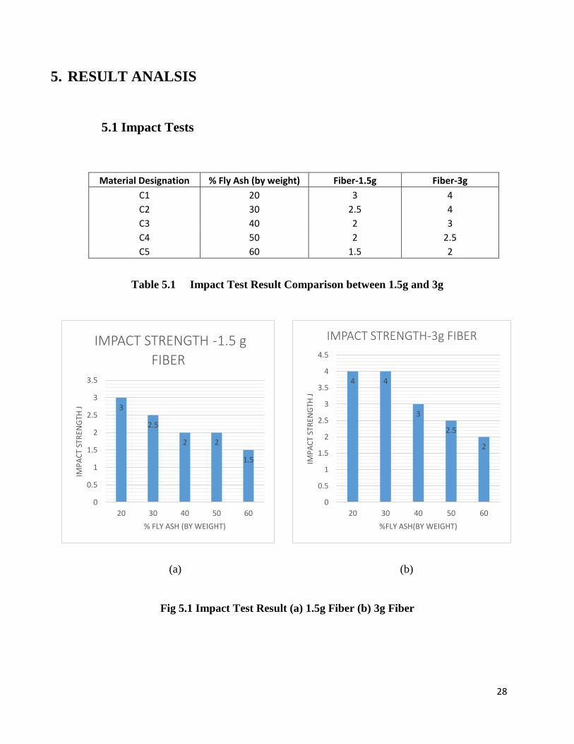
5.1 Impact Tests
Material Designation % Fly Ash (by weight) Fiber-1.5g Fiber-3g
C1 20 3 4
C2 30 2.5 4
C3 40 2 3
C4 50 2 2.5
C5 60 1.5 2
Table 5.1 Impact Test Result Comparison between 1.5g and 3g
(a) (b)
Fig 5.1 Impact Test Result (a) 1.5g Fiber (b) 3g Fiber
3
2.5
2 2
1.5
0
0.5
1
1.5
2
2.5
3
3.5
20 30 40 50 60
IMP
AC
T ST
REN
GTH
J
% FLY ASH (BY WEIGHT)
IMPACT STRENGTH -1.5 g
FIBER
4 4
3
2.5
2
0
0.5
1
1.5
2
2.5
3
3.5
4
4.5
20 30 40 50 60
IMP
AC
T ST
REN
GTH
J
%FLY ASH(BY WEIGHT)
IMPACT STRENGTH-3g FIBER

29
Fig 5.2 Impact Test Result Comparison
Table 5.2 Impact Test Result – Only Fiber in Epoxy
Table 5.3 Impact Test Result – Only Fly Ash and Epoxy
0
0.5
1
1.5
2
2.5
3
3.5
4
4.5
C1 C2 C3 C4 C5
Impact Test Comparison
Fiber-1.5g Fiber-3g
Fiber (by weight g) Impact Strength(Joules)
C-1.5 1
C-3 1.5
Material Designation %Fly Ash(by weight g) Impact Strength(Joules)
C1 20 1
C2 30 1
C3 40 0.75
C4 50 0.5
C5 60 0.5

30
(a) (b)
Fig. 5.3 Impact Test Result – (a) Only Fiber, (b) Only Fly Ash
With increase in fiber content Impact strength increases (Fig.5.3.a), higher the amount of fly ash
content in the composite, lower is the impact strength in the composite.
However for composite having same fiber content and different amount of fly ash there is decrease
in impact strength with increase in the fly ash content (Fig.5.2).
When samples with just fly ash and epoxy were taken, the impact strength decreases with increase
in the fly ash content (Fig.5.3.b).
1 1
0.75
0.5 0.5
0
0.2
0.4
0.6
0.8
1
1.2
20 30 40 50 60
imp
act
stre
ngt
h j
%fly ash (by weight)
Imapact Strength(Joules)
1
1.5
0
0.2
0.4
0.6
0.8
1
1.2
1.4
1.6
1.5 3
IMP
AC
T ST
REN
GTH
J
FIBER (in grams)
Imapact Strength(Joules)
31
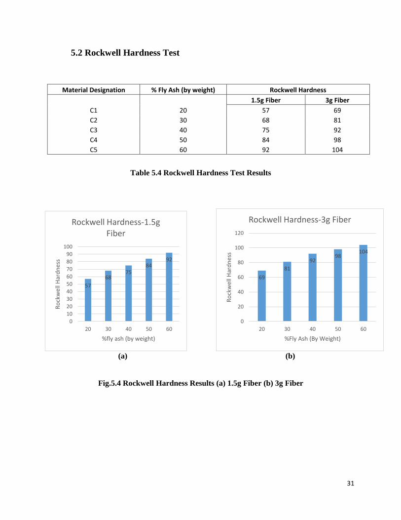
5.2 Rockwell Hardness Test
Material Designation % Fly Ash (by weight) Rockwell Hardness
1.5g Fiber 3g Fiber
C1 20 57 69
C2 30 68 81
C3 40 75 92
C4 50 84 98
C5 60 92 104
Table 5.4 Rockwell Hardness Test Results
(a) (b)
Fig.5.4 Rockwell Hardness Results (a) 1.5g Fiber (b) 3g Fiber
57
6875
8492
0
10
20
30
40
50
60
70
80
90
100
20 30 40 50 60
Ro
ckw
ell H
ard
nes
s
%fly ash (by weight)
Rockwell Hardness-1.5g Fiber
69
81
9298
104
0
20
40
60
80
100
120
20 30 40 50 60
Ro
ckw
ell H
ard
nes
s
%Fly Ash (By Weight)
Rockwell Hardness-3g Fiber

32
Fig 5.5 Hardness Comparison on Different Fiber Content
Material Designation %Fly Ash(by weight g) Rockwell Hardness
C1 20 B-51
C2 30 B-59
C3 40 B-71
C4 50 B-78
C5 60 B-85
Table 5.5 Rockwell Hardness Number – Only Fly Ash and Epoxy
Fig. 5.6 Rockwell Hardness Number – Only Fly Ash
0
20
40
60
80
100
120
20 30 40 50 60
Rockwell Hardness
1.5g Fiber 3g Fiber
5159
7178
85
0
10
20
30
40
50
60
70
80
90
20 30 40 50 60
rock
we
ll h
ard
ne
ss
%fly ash(by weight)
Rockwell Hardness
33
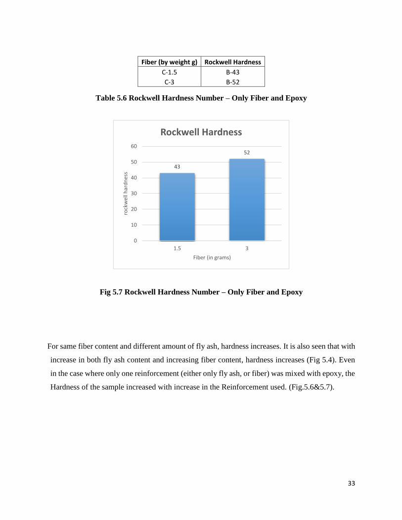
Table 5.6 Rockwell Hardness Number – Only Fiber and Epoxy
Fig 5.7 Rockwell Hardness Number – Only Fiber and Epoxy
For same fiber content and different amount of fly ash, hardness increases. It is also seen that with
increase in both fly ash content and increasing fiber content, hardness increases (Fig 5.4). Even
in the case where only one reinforcement (either only fly ash, or fiber) was mixed with epoxy, the
Hardness of the sample increased with increase in the Reinforcement used. (Fig.5.6&5.7).
43
52
0
10
20
30
40
50
60
1.5 3
rock
wel
l har
dn
ess
Fiber (in grams)
Rockwell Hardness
Fiber (by weight g) Rockwell Hardness
C-1.5 B-43
C-3 B-52

34
5.3 Wear Test
5.3.1 1.5g of Fiber, 50g of Epoxy – Varying Fly Ash (%by Weight)
Fig 5.8 Weight Difference Before and After the Wear Test
(In the figure (fig 5.8) on the Y-Axis, the values are read as “%FlyAsh_Load_RPM”)
0
0.005
0.01
0.015
0.02
0.025
0.03
Weight Difference (W1-W2)
Sample w1 w2 w1-w2
60_1_300 0.786 0.782 0.004
50_1_300 1.027 1 0.001
40_1_300 1.026 1.023 0.003
30_1_300 1.295 1.292 0.003
20_1_300 0.85 0.842 0.008
0
0.002
0.004
0.006
0.008
0.01
60_1_300 50_1_300 40_1_300 30_1_300 20_1_300
1 Kg, 300 RPM
w1-w2
Table 5.7 1Kg load, 300 RPM
Fig 5.9 Change in Wear w.r.t. Change in Fly Ash Content

35
Sample w1 w2 w1-w2
60_1_600 0.92 0.907 0.013
50_1_600 1.484 1.478 0.006
40_1_600 0.939 0.933 0.006
30_1_600 1.201 1.196 0.005
20_1_600 0.855 0.85 0.005
Sample w1 w2 w1-w2
60_2_300 0.9078 0.885 0.0228
50_2_300 1.485 1.484 0.001
40_2_300 1.032 1.026 0.006
30_2_300 1.205 1.201 0.004
20_2_300 0.842 0.835 0.007
Sample w1 w2 w1-w2
60_2_600 0.885 0.86 0.025
50_2_600 1.026 1.012 0.014
40_2_600 0.933 0.923 0.01
30_2_600 1.268 1.264 0.004
20_2_600 0.746 0.642 0.104
0
0.002
0.004
0.006
0.008
0.01
0.012
0.014
60_1_600 50_1_600 40_1_600 30_1_600 20_1_600
1 Kg_600 RPM
w1-w2
Table 5.8 1Kg load, 600 RPM
Fig 5.10 Change in Wear w.r.t. Change in Fly Ash Content
0
0.005
0.01
0.015
0.02
0.025
60_2_300 50_2_300 40_2_300 30_2_300 20_2_300
2 Kg_300 RPM
w1-w2
Table 5.9 2 Kg load, 300 RPM
Fig 5.11 Change in Wear w.r.t. Change in Fly Ash Content
0
0.02
0.04
0.06
0.08
0.1
0.12
60_2_600 50_2_600 40_2_600 30_2_600 20_2_600
2 Kg_600 RPM
w1-w2
Table 5.10 2 Kg load, 600 RPM
Fig 5.12 Change in Wear w.r.t. Change in Fly Ash Content

36
Wear test with 1.5g of Fiber, it is found that with increase in fly ash content there is also decrease
in wear, however this phenomenon is observed only until a certain upper limit i.e. in the wear
resistance increases from 20% to 50 % fly ash but decreases at 60%.
5.3.2 3g of Fiber, 50g of Epoxy – Varying Fly Ash (%by Weight)
Fig 5.13 Weight Difference Before and After the Wear Test
(In the figure (fig 5.13) on the Y-Axis, the values are read as “%FlyAsh_Load_RPM”)
0.012
0.003
0.0012
0.0040.003
0.0016
0.005
0.008
0.0040.0034
0.01
0.0085
0.0030.004
0.0127
0.0101
0.0030.002
0.0040.0049
0
0.002
0.004
0.006
0.008
0.01
0.012
0.014
Weight Difference (W1-W2)
Sample w1 w2 w1-w2
60_1_300 1.258 1.246 0.012
50_1_300 1.071 1 0.003
40_1_300 0.734 0.73 0.004
30_1_300 0.573 0.57 0.003
20_1_300 0.732 0.729 0.003
0
0.002
0.004
0.006
0.008
0.01
0.012
0.014
60_1_300 50_1_300 40_1_300 30_1_300 20_1_300
1 Kg_300 RPM
w1-w2
Table 5.11 1 Kg load, 300 RPM
Fig 5.14 Change in Wear w.r.t. Change in Fly Ash Content
37
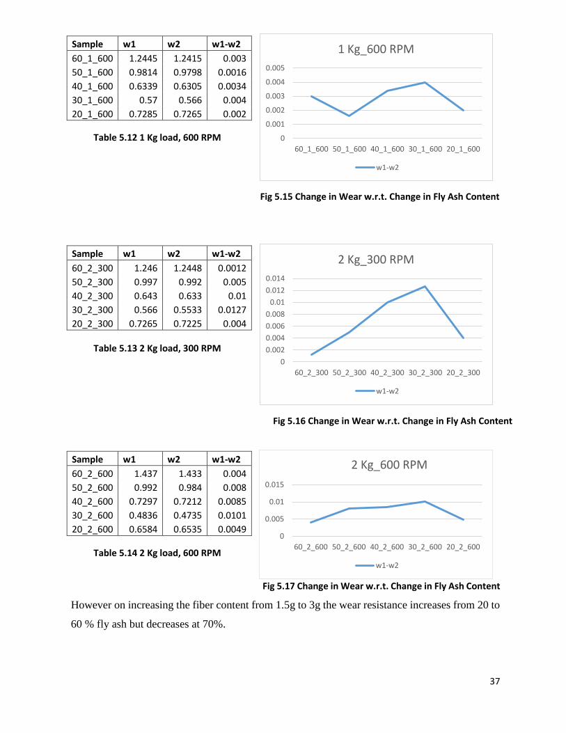
Fig 5.17 Change in Wear w.r.t. Change in Fly Ash Content
However on increasing the fiber content from 1.5g to 3g the wear resistance increases from 20 to
60 % fly ash but decreases at 70%.
Sample w1 w2 w1-w2
60_1_600 1.2445 1.2415 0.003
50_1_600 0.9814 0.9798 0.0016
40_1_600 0.6339 0.6305 0.0034
30_1_600 0.57 0.566 0.004
20_1_600 0.7285 0.7265 0.002
Sample w1 w2 w1-w2
60_2_300 1.246 1.2448 0.0012
50_2_300 0.997 0.992 0.005
40_2_300 0.643 0.633 0.01
30_2_300 0.566 0.5533 0.0127
20_2_300 0.7265 0.7225 0.004
Sample w1 w2 w1-w2
60_2_600 1.437 1.433 0.004
50_2_600 0.992 0.984 0.008
40_2_600 0.7297 0.7212 0.0085
30_2_600 0.4836 0.4735 0.0101
20_2_600 0.6584 0.6535 0.0049
0
0.001
0.002
0.003
0.004
0.005
60_1_600 50_1_600 40_1_600 30_1_600 20_1_600
1 Kg_600 RPM
w1-w2
Table 5.12 1 Kg load, 600 RPM
Fig 5.15 Change in Wear w.r.t. Change in Fly Ash Content
Table 5.13 2 Kg load, 300 RPM
0
0.002
0.004
0.006
0.008
0.01
0.012
0.014
60_2_300 50_2_300 40_2_300 30_2_300 20_2_300
2 Kg_300 RPM
w1-w2
Fig 5.16 Change in Wear w.r.t. Change in Fly Ash Content
0
0.005
0.01
0.015
60_2_600 50_2_600 40_2_600 30_2_600 20_2_600
2 Kg_600 RPM
w1-w2
Table 5.14 2 Kg load, 600 RPM

38
6. CONCLUSIONS
6.1 Impact Test
6.1.1 Only Fiber
There is an increase in impact strength of composite with increase in fiber content
due to energy absorbed in fiber pull out but the overall impact strength of natural
fiber is less than synthetic fiber (Fig. 5.3 (a))
6.1.2 Only Fly Ash
Addition of fly ash to the epoxy has led to the decrease in impact strength. This can
be attributed to the property of particulate reinforced composite where in fly ash
acts as the particulate reinforcement and decreases the overall flexibility making
the composite relatively brittle when added in high amount and due to decreased
availability of epoxy material to bond all the fly ash particles in the matrix, thereby
reducing the impact strength. This can be concluded from the results as shown
(Fig.5.3 (b))
6.1.3 Double Reinforced –Sugarcane Fiber and Fly Ash
After reinforcing the fly ash composite with sugarcane fiber impact strength has
been increased due to energy absorbed in fiber pull out and the fly ash particles.
But as the amount of fly ash increases impact strength falls due to the inability of
epoxy to bond both the fiber and fly ash in the matrix. For two composites having
same fly ash composition but different amount of fiber it can be seen the impact
strength has been increased for high amount of fiber. (Fig 5.1)

39
6.2 Rockwell Hardness
6.2.1 Only Fiber
There is an increase in Rockwell hardness number as fiber content increases
because there is proper interfacial bonding between the fiber and matrix material.
In lesser fiber content there may be areas with in the campsites wherein no fiber is
present but in increase in fiber content these areas reduce and proper bonding
fiber and matrix material is achieved which results in increased hardness.
(Fig.5.7)
6.2.2 Only Fly Ash
As seen from Fig.5.6, an increasing trend of hardness was observed with increase
in weight fraction of fly ash particles .This can be attributed to the presence of
hard fly ash particles in the composites which enhances the dislocation density
which resists the deformation when it is subjected to strain. When the fly ash
content increased from 20 to 60 weight percentage, hardness increased .It can be
explained by the fact that the fly ash particles possess higher hardness, because of
their spherical shape (micro level) it prevents any indentation.
6.2.3 Double Reinforced –Sugarcane Fiber and Fly Ash
After reinforcing fiber and fly ash Rockwell hardness number increases. This is
because the fly ash fuses appropriately around the fiber forming a strong bond
with it.
As it can be seen from the results with increase in fly ash on same fiber content
hardness increases, this can be attributed to the more fly ash content which resists
deformation to strain (Fig5.5).

40
6.3 Wear Test
6.3.1 For 1.5 gram Fiber Content
The sample of wear test in which least material is lost has the best wear property.
From the graphs it can be observed that specimen to 30% from 50% weights have
better wear property as compared to others. The spherical microstructure of fly ash
is assumed to be one of the reason due to which god wear resistance is obtained
with increase in fly ash content.
Wear grooves and scratches along the sliding direction were smaller due to the
presence of fly ash particulates. This shows that the presence of fly ash in the matrix
improves resistance to wear. Applied load affects the wear behavior of composites
and is the most dominating factor in controlling the wear rate
When the two surfaces are in sliding contact, wear mechanisms such as surface
abrasion, oxidation, delamination and adhesion may happen either separately or in
combination.
6.3.2 For 3 gram Fiber Content
The lowest wear loss was obtained for composite with 50 weight % at 1.5g Fiber
whereas 60 weight % had the least wear loss in 3g fiber as compared to composites
reinforced with 20 weight %, 30 weight %, 40weightt% fly ash at varying speeds
and load conditions. This is because incorporation of fly ash particles have
increased the hardness of the composites (Fig.5.5) .This increase in wear resistance
can also be attributed to a better interfacial bonding between matrix material,
fiber and fly ash particles and thus helps in preventing the damages caused due to
sliding action.
Incorporation of fly ash particles to the sugarcane matrix was very effective in
reducing its wear loss. This is because of the strong interfacial bond which plays a
41
vital role in transferring loads from the sugarcane matrix to the hard fly ash
particles.
As the fly ash content increases beyond some proportion the wear loss increased
with increasing the load. This may be due to clustering of fly ash particles and poor
interfacial bonding between sugarcane matrix and fly ash particles. This was proven
by the fact that the wear resistance increased from 50% by weight fly ash (in case
of 1.5g fiber content) to 60% by weight fly ash (in case of 3g fiber content). Beyond
these two cases, the wear resistance of the sample decreased, and higher weight loss
due to wear.
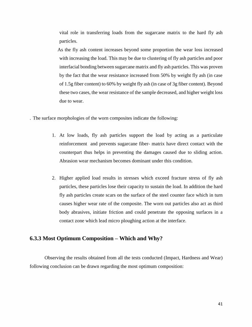
. The surface morphologies of the worn composites indicate the following:
1. At low loads, fly ash particles support the load by acting as a particulate
reinforcement and prevents sugarcane fiber- matrix have direct contact with the
counterpart thus helps in preventing the damages caused due to sliding action.
Abrasion wear mechanism becomes dominant under this condition.
2. Higher applied load results in stresses which exceed fracture stress of fly ash
particles, these particles lose their capacity to sustain the load. In addition the hard
fly ash particles create scars on the surface of the steel counter face which in turn
causes higher wear rate of the composite. The worn out particles also act as third
body abrasives, initiate friction and could penetrate the opposing surfaces in a
contact zone which lead micro ploughing action at the interface.
6.3.3 Most Optimum Composition – Which and Why?
Observing the results obtained from all the tests conducted (Impact, Hardness and Wear)
following conclusion can be drawn regarding the most optimum composition:

42
1. In Impact test, the strength of the sample decreased with increase in fly ash,
whereas when we increased the fiber content strength of the sample increased.
Hence it can be said that, the sample with 3g of fiber, and 30% of fly ash by
weight, showed the highest Strength.
2. In the Rockwell tests, the increase in both fiber and fly ash content, helped in
the hardness of the sample. Hence, the sample with 3g fiber and 60% of fly ash
by weight, was the hardest sample.
3. The Wear Tests showed results favoring higher Fiber content, but increase in
fly ash after certain limit lead to increase in wear. Also, in low load conditions,
50% by weight of fly ash Sample showed most optimum results, both in low
and high fiber content. In high load conditions, 30% by weight of fly ash was
the most optimum sample in 1.5g fiber content, and 60% by weight of fly ash
had the least wear in case of 3g of fiber content.
Looking at the results, we can say that, the optimum composition can be decided as per the
application it will be used for.
In the case where high speed and low weight material is required, like in automobile sector, 30%
by weight of fly ash sample, will be most optimum. It will have high strength and good wear
resistance as well.
In 60% by weight of fly ash sample with 3g of fiber can be used where weight of the sample is not
a constrain, as increasing in the fly ash content will lead to increase in the weight of the sample.
But this increase in fly ash will result in higher hardness but lower impact strength. It will find
applications where high loads are applied and the material is used for wear purpose only.
In 50% by weight of fly ash sample is good with both 1.5g and 3g sample. With moderate hardness
and moderate impact strength as compared to 30% and 60% samples. This has lighter weight than
the 60% by weight of fly ash sample, and higher wear resistance than the 30% sample in case of
higher loads. Hence we can say that, it can be taken as the optimum sample, provided the
applications it is used for doesn’t require high strength.

43
7. APPLICATIONS OF THE MATERIAL
The high wear resistance, good hardness and impact strength of the composite can be
used in various application .Also the property of the fly ash to resist compression is
significant in development of the application of the composite.
7.1 Coupling
Good torsional strength, compression resistance and the ability to resist shear helps
it in coupling 2 different shafts of varying diameters. The hardness of the composite
is found to be in between that of a steel and aluminum. This property can effectively
be used in joining two shafts made of aluminum and steel which otherwise would
eat into each other.
7.2 Plunger
The addition of fly ash makes the composite wear resistant and can be used in
making plunger head. Also the light weight of the composite is another important
property that helps us make the plunger lighter in comparison with traditional
plungers.
7.3 Others
Other fields where there might be future scope for the application of the composites
are in the field of Prosthetic Limbs. The composite can take huge amount of
compression load with good wear resistance hence there is good scope for is use in
the prosthetic medicine.

44
8. SCOPE FOR FUTURE WORK
1. In the present investigation a hand-lay-up technique was used to fabricate the composite.
However there exists other manufacturing process for polymer matrix composite. They
could be tried and analyzed, so that a final conclusion can be drawn there from. However
the results provided in this thesis can act as a base for the utilization of this fiber.
2. From this work it is found that chemical modification of the fiber with alkali significantly
improves the mechanical performance of the composite. Other chemical modification
methods such as silane treatment, acetylation treatment, acrylation treatment isocynates
treatment, Permanganate treatment, Maleated coupling agents could be tried and a final
conclusion can be drawn thereafter.
3. This work can be further extended to other particle size and types of particle like glass bead
etc., to study the effect of particle size and type of particles on wear behavior of the composite.
4. More compositions of the fiber, fly ash and epoxy can be tried to observe the behavior of
the composite more closely. Instead of adding the fiber and fly ash with respect to weight,
they can be added by percentage of volume and the results for the same can be studied.

45
REFERENCES
1. www.nptel.ac.in
2. www.Wikipedia.com
3. Development and characterization of low cost composite from sugarcane bagasse waste
Department of Mechanical Engineering National Institute of Technology Rourkela -
769 008 (India)
4. Mechanical Properties of Epoxy Resin – Fly Ash Composite 2Department of Materials
& Metallurgical Effect of Fly Ash Content on Friction and Dry Sliding Wear Behavior
of Glass
5. Fiber Reinforced Polymer Composites - A Taguchi Approachgineering, I.I.T. Roorkee
(Uttaranchal), INDIA
6. Experimental Evaluation of Aluminium-Fly Ash Composite Material to Increase the
Mechanical &Wear Behaviour by Stir Casting Method1: PG Scholar, Dept of Mech,
Mokambigai college of Engineering Professor, Dept of Mech, Mokambigai college of
Engineering
7. Chand N. SEM observations of fractured fly-polyester composites. J Mat Sci Lett
1988;7:
8. 36–8.Bijwe, J., Logani, C.M. and Tewari, U.S., 1989, “Influence of fillers and fibre
reinforcement on abrasive wear resistance of some polymeric composites”, In:
Proceeding of the International Conference on Wear of Materials, Denver, CO, USA,
April 8–14, pp. 75–92.
9. Khuri, A.I. and Cornell, J.A., 1987, “Response Surfaces. Designs and Analyses”, Vol.
81 of Statistics, Textbooks and Monographs, Marcel Dekker, Inc. ASQC, New York.
10. Barkoula, N.M. and Karger-Kocsis, J., 2002, “Review-processes and influencing
parameters of the solid particle erosion of polymers and their composites”, J.
Mater. Sci.; 37: pp. 3807–3820.