CATV 75 Ω Push Pull Amplifier 45 - 1200 MHz Rev. V2 MAAM-011169 M/A-COM Technology Solutions Inc. (MACOM) and its affiliates reserve the right to make changes to the product(s) or information contained herein without notice. Visit www.macom.com for additional data sheets and product information. For further information and support please visit: https://www.macom.com/support 1 Features 25 dB Gain 12 Volts DC Bias Differential Inputs and Outputs Low Distortion Adjustable Bias Current and Gain Control Lead-Free 5 x 7 mm 40-Lead PQFN Package Halogen-Free “Green” Mold Compound RoHS* Compliant Description The MAAM-011169 is a GaAs MMIC amplifier configured as two stages of differential amplifiers for broadband performance. It is optimized for very low distortion and noise figure in a 75 Ω push-pull amplifier circuit. It provides excellent input and output return loss over the 45 to 1200 MHz operating frequencies. The device is ideally suited for CATV applications including line amplifiers, HFC, and FTTL nodes. Ordering Information 1,2 Part Number Package MAAM-011169 Bulk Packaging MAAM-011169-TR1000 1000 Piece Reel MAAM-011169-TR3000 3000 Piece Reel MAAM-011169-001SMB Sample Test Board 1. Reference Application Note M513 for reel size information. 2. All sample boards include 5 loose parts. Functional Schematic 3. MACOM recommends connecting all No Connection (N/C) pins to ground. 4. The exposed pad centered on the package bottom must be connected to RF and DC ground. Pin Configuration 3 Pin No. Pin Name Description All pins not marked N/C No Connection 3 RF IN A Amp1 RF in+ 7 V G 1 Amp1 DC Adjust 10 RF IN B Amp1 RF in- 13 V DD 1B Amp1 DC- 15 RF OUT 1B Amp1 RF out- 18 RF IN 2B Amp2 RF in- 23 RF OUT B Amp2 RF out- 26 V CG Amp2 DC Bias 27 V G 2 Amp2 DC Adjust 30 RF OUT A Amp2 RF out+ 35 RF IN 2A Amp2 RF in+ 38 RF OUT 1A Amp1 RF out+ 40 V DD 1A Amp1 DC+ 41 Paddle 4 Ground * Restrictions on Hazardous Substances, European Union Directive 2011/65/EU. RFINA 7 8 9 40 39 38 37 36 35 34 33 13 14 15 16 17 18 19 20 1 2 3 4 5 6 7 8 9 10 11 12 32 31 30 29 28 27 26 25 24 23 22 21 VG1 RFINB V DD 1B RF OUT 1B RF IN 2B RFOUTA RFOUTB VG2 VCG V DD 1A RF OUT 1A RF IN 2A

Welcome message from author
This document is posted to help you gain knowledge. Please leave a comment to let me know what you think about it! Share it to your friends and learn new things together.
Transcript

CATV 75 Ω Push Pull Amplifier 45 - 1200 MHz
Rev. V2
MAAM-011169
1 1
M/A-COM Technology Solutions Inc. (MACOM) and its affiliates reserve the right to make changes to the product(s) or information contained herein without notice. Visit www.macom.com for additional data sheets and product information.
For further information and support please visit: https://www.macom.com/support
1
Features
25 dB Gain
12 Volts DC Bias
Differential Inputs and Outputs
Low Distortion
Adjustable Bias Current and Gain Control
Lead-Free 5 x 7 mm 40-Lead PQFN Package
Halogen-Free “Green” Mold Compound
RoHS* Compliant
Description
The MAAM-011169 is a GaAs MMIC amplifier configured as two stages of differential amplifiers for broadband performance. It is optimized for very low distortion and noise figure in a 75 Ω push-pull amplifier circuit. It provides excellent input and output return loss over the 45 to 1200 MHz operating frequencies. The device is ideally suited for CATV applications including line amplifiers, HFC, and FTTL nodes.
Ordering Information1,2
Part Number Package
MAAM-011169 Bulk Packaging
MAAM-011169-TR1000 1000 Piece Reel
MAAM-011169-TR3000 3000 Piece Reel
MAAM-011169-001SMB Sample Test Board
1. Reference Application Note M513 for reel size information. 2. All sample boards include 5 loose parts.
Functional Schematic
3. MACOM recommends connecting all No Connection (N/C) pins to ground.
4. The exposed pad centered on the package bottom must be connected to RF and DC ground.
Pin Configuration3
Pin No. Pin Name Description
All pins not marked N/C No Connection
3 RFINA Amp1 RF in+
7 VG1 Amp1 DC Adjust
10 RFINB Amp1 RF in-
13 VDD1B Amp1 DC-
15 RFOUT1B Amp1 RF out-
18 RFIN2B Amp2 RF in-
23 RFOUTB Amp2 RF out-
26 VCG Amp2 DC Bias
27 VG2 Amp2 DC Adjust
30 RFOUTA Amp2 RF out+
35 RFIN2A Amp2 RF in+
38 RFOUT1A Amp1 RF out+
40 VDD1A Amp1 DC+
41 Paddle4 Ground * Restrictions on Hazardous Substances, European Union Directive 2011/65/EU.
RFINA
78
9
40 39 38 37 36 35 34 33
13 14 15 16 17 18 19 20
1
2
3
4
5
6
7
8
9
10
11
12
32
31
30
29
28
27
26
25
24
23
22
21
VG1
RFINB
VD
D1B
RF
OU
T1B
RF
IN2B
RFOUTA
RFOUTB
VG2
VCG
VD
D1A
RF
OU
T1A
RF
IN2A
CATV 75 Ω Push Pull Amplifier 45 - 1200 MHz
Rev. V2
MAAM-011169
2 2
M/A-COM Technology Solutions Inc. (MACOM) and its affiliates reserve the right to make changes to the product(s) or information contained herein without notice. Visit www.macom.com for additional data sheets and product information.
For further information and support please visit: https://www.macom.com/support
2
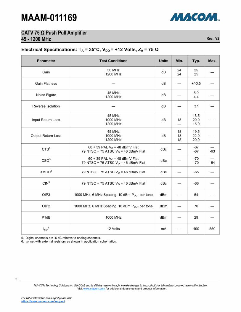
Electrical Specifications: TA = 35°C, VDD = +12 Volts, Z0 = 75 Ω
5. Digital channels are -6 dB relative to analog channels. 6. IDD set with external resistors as shown in application schematics.
Parameter Test Conditions Units Min. Typ. Max.
Gain 50 MHz
1200 MHz dB
24 24
25 25
—
Gain Flatness — dB — +/-0.5 —
Noise Figure 45 MHz
1200 MHz dB —
5.9 4.4
—
Reverse Isolation — dB — 37 —
Input Return Loss 45 MHz
1000 MHz 1200 MHz
dB — 18 —
18.5 20.0 15.0
—
Output Return Loss 45 MHz
1000 MHz 1200 MHz
dB 18 18 18
19.5 22.0 20.0
—
CTB5 60 + 39 PAL VO = 48 dBmV Flat
79 NTSC + 75 ATSC VO = 46 dBmV Flat dBc —
-67 -67
— -63
CSO5 60 + 39 PAL VO = 48 dBmV Flat
79 NTSC + 75 ATSC VO = 46 dBmV Flat dBc —
-70 -70
— -64
XMOD5 79 NTSC + 75 ATSC VO = 46 dBmV Flat dBc — -65 —
CIN5 79 NTSC + 75 ATSC VO = 46 dBmV Flat dBc — -66 —
OIP3 1000 MHz, 6 MHz Spacing, 10 dBm POUT per tone dBm — 54 —
OIP2 1000 MHz, 6 MHz Spacing, 10 dBm POUT per tone dBm — 70 —
P1dB 1000 MHz dBm — 29 —
IDD6 12 Volts mA — 490 550

CATV 75 Ω Push Pull Amplifier 45 - 1200 MHz
Rev. V2
MAAM-011169
3 3
M/A-COM Technology Solutions Inc. (MACOM) and its affiliates reserve the right to make changes to the product(s) or information contained herein without notice. Visit www.macom.com for additional data sheets and product information.
For further information and support please visit: https://www.macom.com/support
3
Maximum Operating Conditions7
Handling Procedures
Please observe the following precautions to avoid damage:
Static Sensitivity
These electronic devices are sensitive to electrostatic discharge (ESD) and can be damaged by static electricity. Proper ESD control techniques should be used when handling these devices.
Parameter Absolute Maximum
RF Input Power 4 dBm
Voltage 12 Volts
Operating Temperature -40°C to +100°C
Junction Temperature8 +150°C
Parameter Absolute Maximum
RF Input Power 9 dBm
Voltage 15 Volts
Storage Temperature -65°C to +150°C
Absolute Maximum Ratings9,10
Printed Circuit Board Thermal Design To maintain reliable junction temperatures for this high power amplifier the printed circuit board (PCB) must provide low thermal resistance to the exposed paddle of the IC package. In general, thinner substrates and thicker plating for vias provide lower thermal resistance. Calculation of case temperature must include temperature rise in PCB.
Thermal Via Array, 62-mil PCB
101 total vias. Vias plated to minimum 1.5-mil (38 µm) thickness of copper. Finished via diameter minimum 9.9 mils (0.25 mm) 2-oz (70 µm) thick copper for top and bottom metal. Vias not necessary to be filled.
7. Operating at nominal conditions with TJ ≤ +150°C will ensure
MTTF > 1 x 10⁶ hours.
8. Junction Temperature (TJ) = TC + ӨJC * (V * I)
Typical thermal resistance (ӨJC) = 6.3 °C/W.
a) For TC = +35°C,
TJ = 72°C @ 12 V, 495 mA
b) For TC = +100°C,
TJ = 137°C @ 12 V, 495 mA
9. Exceeding any one or combination of these limits may cause permanent damage to this device.
10. MACOM does not recommend sustained operation near these survivability limits.

CATV 75 Ω Push Pull Amplifier 45 - 1200 MHz
Rev. V2
MAAM-011169
4 4
M/A-COM Technology Solutions Inc. (MACOM) and its affiliates reserve the right to make changes to the product(s) or information contained herein without notice. Visit www.macom.com for additional data sheets and product information.
For further information and support please visit: https://www.macom.com/support
4
Application Schematic
Recommended PCB Layout

CATV 75 Ω Push Pull Amplifier 45 - 1200 MHz
Rev. V2
MAAM-011169
5 5
M/A-COM Technology Solutions Inc. (MACOM) and its affiliates reserve the right to make changes to the product(s) or information contained herein without notice. Visit www.macom.com for additional data sheets and product information.
For further information and support please visit: https://www.macom.com/support
5
Recommended Off-Chip Component Values
Component Value Package QTY Vendor Part Number
C1, C2, C3, C4, C7, C9, C10, C11, C12, C14, C16, C19, C21
10 nF 0402 13 MURATA GRM155R71H103KA88D
C13, C15, C17, C18, C20 1000 pF 0402 5 MURATA GRM155R71H102KA01D
C5, C6 270 pF 0402 2 MURATA GRM1555C1H271JA01D
C8 0.6 pF 0402 1 MURATA GRM1555C1HR60BA01D
L5, L6 1800 Ω 0402 2 MURATA
BLM15HD182SN1D
L7, L8, L9, L10 1500 Ω 0603 4 MURATA
BLM18HE152SN1D
L3, L4 2.7 nH 0402 2 MURATA LQG15HS2N7S02D
L1, L2 2.2 nH 0402 2 MURATA LQG15HS2N2S02D
R13 562 Ω 0402 1 PANASONIC ERJ-2RKF5620X
R4, R5 499 Ω 0402 2 PANASONIC ERJ-2RKF4990X
R9, R11 300 Ω 0402 2 ROHM ESR01MZPJ301
R2, R3 215 Ω 0402 2 PANASONIC ERJ-2RKF2150X
R10 200 Ω 0603 1 ROHM ESR03EZPF2000
R12 158 Ω 0402 1 PANASONIC ERJ-2RKF1580X
R14, R15, R16, R17 20 Ω 0603 4 ROHM ESR03EZPJ200
R1, R6, R7, R8, R18 0 Ω 0402 5 PANASONIC ERJ-2GE0R00X
Balun T1 1:1 — 1 MACOM MABA-010321-CT1A42
Balun T2 1:2 — 1 MACOM MABA-011029

CATV 75 Ω Push Pull Amplifier 45 - 1200 MHz
Rev. V2
MAAM-011169
6 6
M/A-COM Technology Solutions Inc. (MACOM) and its affiliates reserve the right to make changes to the product(s) or information contained herein without notice. Visit www.macom.com for additional data sheets and product information.
For further information and support please visit: https://www.macom.com/support
6
Typical Performance Curves
Gain Reverse Isolation
Input Return Loss Output Return Loss
Noise Figure
20
22
24
26
28
30
0.0 0.2 0.4 0.6 0.8 1.0 1.2
+35°C-40°C+85°C
S2
1 (
dB
)
Frequency (GHz)
-50
-45
-40
-35
-30
-25
0.0 0.2 0.4 0.6 0.8 1.0 1.2
+35°C-40°C+85°C
Iso
latio
n (
dB
)
Frequency (GHz)
-40
-30
-20
-10
0
0.0 0.2 0.4 0.6 0.8 1.0 1.2
+35°C-40°C+85°C
S1
1 (
dB
)
Frequency (GHz)
-40
-30
-20
-10
0
0.0 0.2 0.4 0.6 0.8 1.0 1.2
+35°C-40°C+85°C
S2
2 (
dB
)
Frequency (GHz)
1
2
3
4
5
6
7
0.0 0.2 0.4 0.6 0.8 1.0 1.2
+35°C-40°C+85°C
No
ise F
igu
re (
dB
)
Frequency (GHz)

CATV 75 Ω Push Pull Amplifier 45 - 1200 MHz
Rev. V2
MAAM-011169
7 7
M/A-COM Technology Solutions Inc. (MACOM) and its affiliates reserve the right to make changes to the product(s) or information contained herein without notice. Visit www.macom.com for additional data sheets and product information.
For further information and support please visit: https://www.macom.com/support
7
Composite Triple Beat Composite Second Order
Typical Distortion Performance Curves @ +35°C:
99 PAL VO = 48 dBmV/CH Flat in 60 Analog Channels, VO = 42 dBmV Flat in 39 Digital Channels
-80
-75
-70
-65
-60
0 100 200 300 400 500 600
CT
B (
dB
c)
Frequency (MHz)
-100
-90
-80
-70
-60
0 100 200 300 400 500 600
CSO_highCSO_low
CS
O (
dB
c)
Frequency (MHz)

CATV 75 Ω Push Pull Amplifier 45 - 1200 MHz
Rev. V2
MAAM-011169
8 8
M/A-COM Technology Solutions Inc. (MACOM) and its affiliates reserve the right to make changes to the product(s) or information contained herein without notice. Visit www.macom.com for additional data sheets and product information.
For further information and support please visit: https://www.macom.com/support
8
Cross Modulation Carrier to Intermodulation Noise
Composite Triple Beat Composite Second Order
Typical Distortion Performance Curves @ +35°C:
VO = 46 dBmV/CH Flat in 79 NTSC Analog Channels, VO = 40 dBmV Flat in 75 ATSC Digital Channels
-80
-75
-70
-65
-60
0 100 200 300 400 500 600
CT
B (
dB
c)
Frequency (MHz)
-100
-90
-80
-70
-60
0 100 200 300 400 500 600
CSO_highCSO_low
CS
O (
dB
c)
Frequency (MHz)
-75
-70
-65
-60
-55
0 100 200 300 400 500 600
XM
OD
(dB
c)
Frequency (MHz)
-80
-75
-70
-65
-60
0 100 200 300 400 500 600
CIN
(dB
c)
Frequency (MHz)

CATV 75 Ω Push Pull Amplifier 45 - 1200 MHz
Rev. V2
MAAM-011169
9 9
M/A-COM Technology Solutions Inc. (MACOM) and its affiliates reserve the right to make changes to the product(s) or information contained herein without notice. Visit www.macom.com for additional data sheets and product information.
For further information and support please visit: https://www.macom.com/support
9
† Reference Application Note M538 for lead-free solder reflow recommendations.
Meets JEDEC Moisture Sensitivity Level 1 requirements. Plating is NiPdAu.
Lead-Free 5 x 7 mm 40-Lead PQFN†

CATV 75 Ω Push Pull Amplifier 45 - 1200 MHz
Rev. V2
MAAM-011169
10 10
M/A-COM Technology Solutions Inc. (MACOM) and its affiliates reserve the right to make changes to the product(s) or information contained herein without notice. Visit www.macom.com for additional data sheets and product information.
For further information and support please visit: https://www.macom.com/support
10
M/A-COM Technology Solutions Inc. All rights reserved. Information in this document is provided in connection with M/A-COM Technology Solutions Inc ("MACOM")products. These materials are provided by MACOM as a service to its customers and may be used for informational purposes only. Except as provided in MACOM's Terms and Conditions of Sale for such products or in any separate agreement related to this document, MACOM assumes no liability whatsoever. MACOM assumes no responsibility for errors or omissions in these materials. MACOM may make changes to specifications and product descriptions at any time, without notice. MACOM makes no commitment to update the information and shall have no responsibility whatsoever for conflicts or incompatibilities arising from future changes to its specifications and product descriptions. No license, express or implied, by estoppels or otherwise, to any intellectual property rights is granted by this document. THESE MATERIALS ARE PROVIDED "AS IS" WITHOUT WARRANTY OF ANY KIND, EITHER EXPRESS OR IMPLIED, RELATING TO SALE AND/OR USE OF MACOM PRODUCTS INCLUDING LIABILITY OR WARRANTIES RELATING TO FITNESS FOR A PARTICULAR PURPOSE, CONSEQUENTIAL OR INCIDENTAL DAMAGES, MERCHANTABILITY, OR INFRINGEMENT OF ANY PATENT, COPYRIGHT OR OTHER INTELLECTUAL PROPERTY RIGHT. MACOM FURTHER DOES NOT WARRANT THE ACCURACY OR COMPLETENESS OF THE INFORMATION, TEXT, GRAPHICS OR OTHER ITEMS CONTAINED WITHIN THESE MATERIALS. MACOM SHALL NOT BE LIABLE FOR ANY SPECIAL, INDIRECT, INCIDENTAL, OR CONSEQUENTIAL DAMAGES, INCLUDING WITHOUT LIMITATION, LOST REVENUES OR LOST PROFITS, WHICH MAY RESULT FROM THE USE OF THESE MATERIALS. MACOM products are not intended for use in medical, lifesaving or life sustaining applications. MACOM customers using or selling MACOM products for use in such applications do so at their own risk and agree to fully indemnify MACOM for any damages resulting from such improper use or sale.
Related Documents