MaaB arquitectura y urbanismo slp ANEXO III - CALCULO ESTRUCTURAL C/Tristan de Leguizamon 1, bajo - 48007 Bilbao - 94 423 18 37 - [email protected] REHABILITACION ENVOLVENTE TERMICA EDIFICIO DE VIVIENDAS. LAUBIDETA 6B. DURANGO 1 PROYECTO DE EJECUCIÓN: REHABILITACIÓN DE LA ENVOLVENTE TÉRMICA EDIFICIO DE VIVIENDAS. Laubideta 6B, Durango. CÁLCULO ESTRUCTURAL Los paneles prefabricados de fachada pesan aproximadamente 75 kg/m2; ello unido a sus generosas dimensiones hace que sea necesario diseñar unos anclajes que lleven directamente la carga a la estructura del inmueble. Como vemos en las imágenes se ha optado por una placa rectangular, unida mediante 6 anclajes químicos a las vigas perimetrales del edificio. Sobre la placa va soldada un perfil laminado en “U”, que será de dónde se cuelgan los paneles.

Welcome message from author
This document is posted to help you gain knowledge. Please leave a comment to let me know what you think about it! Share it to your friends and learn new things together.
Transcript

MaaB arquitectura y urbanismo slp ANEXO III - CALCULO ESTRUCTURAL
C/Tristan de Leguizamon 1, bajo - 48007 Bilbao - 94 423 18 37 - [email protected]
REHABILITACION ENVOLVENTE TERMICA EDIFICIO DE VIVIENDAS. LAUBIDETA 6B. DURANGO 1
PROYECTO DE EJECUCIÓN: REHABILITACIÓN DE LA ENVOLVENTE TÉRMICA EDIFICIO DE VIVIENDAS. Laubideta 6B, Durango.
CÁLCULO ESTRUCTURAL
Los paneles prefabricados de fachada pesan aproximadamente 75 kg/m2; ello unido a sus
generosas dimensiones hace que sea necesario diseñar unos anclajes que lleven
directamente la carga a la estructura del inmueble.
Como vemos en las imágenes se ha optado por una placa rectangular, unida mediante 6
anclajes químicos a las vigas perimetrales del edificio. Sobre la placa va soldada un perfil
laminado en “U”, que será de dónde se cuelgan los paneles.
MaaB arquitectura y urbanismo slp ANEXO III - CALCULO ESTRUCTURAL
C/Tristan de Leguizamon 1, bajo - 48007 Bilbao - 94 423 18 37 - [email protected]
REHABILITACION ENVOLVENTE TERMICA EDIFICIO DE VIVIENDAS. LAUBIDETA 6B. DURANGO 2
El cálculo de los ganchos y la estructura del propio panel han sido calculados y
comprobados por el consorcio RENOZEB, mientras que la placa y sus anclajes los ha
calculado MaaB arquitectura.
1.1. CÁLCULO DE LAS PLACAS DE ANCLAJE – MAAB ARQUITECTURA
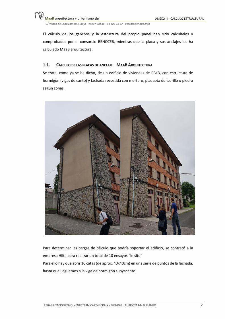
Se trata, como ya se ha dicho, de un edificio de viviendas de PB+3, con estructura de
hormigón (vigas de canto) y fachada revestida con mortero, plaqueta de ladrillo o piedra
según zonas.
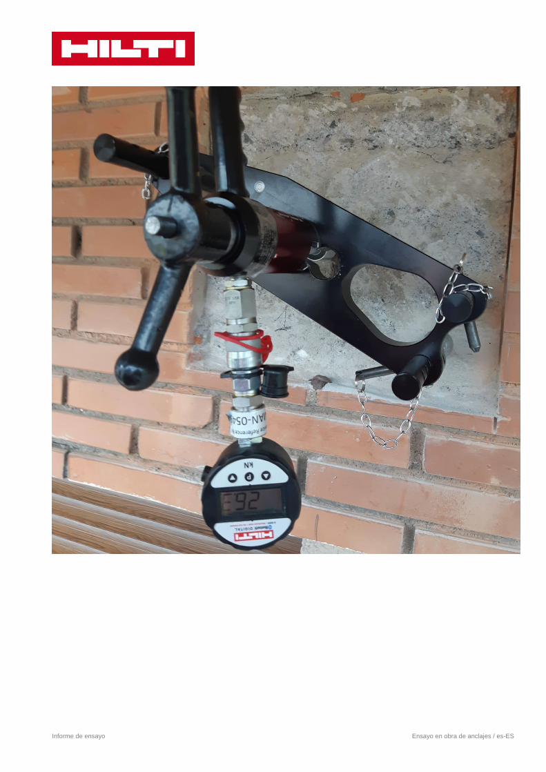
Para determinar las cargas de cálculo que podría soportar el edificio, se contrató a la
empresa Hilti, para realizar un total de 10 ensayos “in situ”
Para ello hay que abrir 10 catas (de aprox. 40x40cm) en una serie de puntos de la fachada,
hasta que lleguemos a la viga de hormigón subyacente.

MaaB arquitectura y urbanismo slp ANEXO III - CALCULO ESTRUCTURAL
C/Tristan de Leguizamon 1, bajo - 48007 Bilbao - 94 423 18 37 - [email protected]
REHABILITACION ENVOLVENTE TERMICA EDIFICIO DE VIVIENDAS. LAUBIDETA 6B. DURANGO 3
La distribución aproximada de las catas es la que se indica a continuación:
Realización de los ensayos de tracción
sobre el hormigón tras la apertura de
las catas
1
4
2
3
5 10
9
8
7
6

MaaB arquitectura y urbanismo slp ANEXO III - CALCULO ESTRUCTURAL
C/Tristan de Leguizamon 1, bajo - 48007 Bilbao - 94 423 18 37 - [email protected]
REHABILITACION ENVOLVENTE TERMICA EDIFICIO DE VIVIENDAS. LAUBIDETA 6B. DURANGO 4
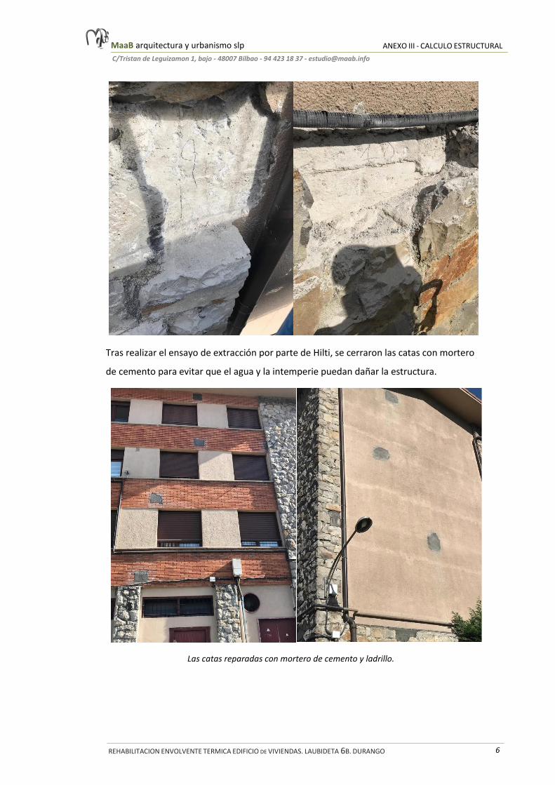
A continuación se aportan una serie de fotos de las catas (antes de realizar el ensayo),
donde se ha aprovechado para realizar un reconocimiento visual del hormigón:

MaaB arquitectura y urbanismo slp ANEXO III - CALCULO ESTRUCTURAL
C/Tristan de Leguizamon 1, bajo - 48007 Bilbao - 94 423 18 37 - [email protected]
REHABILITACION ENVOLVENTE TERMICA EDIFICIO DE VIVIENDAS. LAUBIDETA 6B. DURANGO 5
MaaB arquitectura y urbanismo slp ANEXO III - CALCULO ESTRUCTURAL
C/Tristan de Leguizamon 1, bajo - 48007 Bilbao - 94 423 18 37 - [email protected]
REHABILITACION ENVOLVENTE TERMICA EDIFICIO DE VIVIENDAS. LAUBIDETA 6B. DURANGO 6
Tras realizar el ensayo de extracción por parte de Hilti, se cerraron las catas con mortero
de cemento para evitar que el agua y la intemperie puedan dañar la estructura.
Las catas reparadas con mortero de cemento y ladrillo.

MaaB arquitectura y urbanismo slp ANEXO III - CALCULO ESTRUCTURAL
C/Tristan de Leguizamon 1, bajo - 48007 Bilbao - 94 423 18 37 - [email protected]
REHABILITACION ENVOLVENTE TERMICA EDIFICIO DE VIVIENDAS. LAUBIDETA 6B. DURANGO 7
En la documentación técnica de Hilti que acompaña a este escrito se detalla el tipo de
ensayo y los parámetros técnicos del estudio, aparte de ello a continuación proponemos
una serie de recomendaciones:
Para este tipo de estructuras con cargas medias/altas sobre hormigón fisurado, es
más adecuado el anclaje químico que el mecánico.
Se mantendrá el tipo de anclaje recomendado por Hilti: HIT-HY 200-A (Resina) + HAS-
U 8.8 M12 (barra roscada)
También hay que mantener el diámetro de la barra (12mm), y la profundidad de
empotramiento (70mm). Esto es porque en la fachada lateral (catas de 6 al 10),
contamos con una viga de canto de solo 100mm de anchura.
La separación entre anclajes se comprueba automáticamente en el programa de
cálculo de Hilti
Las cargas máximas de diseño por anclajes serían 5,3 Kn a tracción (fallo por cono del
hormigón) y 3,6 Kn a cortante (fallo por brazo de palanca)
En la documentación adjunta se han comprobado las placas propuestas por MaaB con
6 anclajes.
El grosor de Mortero de alta resistencia (grout) a disponer entre la placa y el hormigón
existente será definido por Focchi, pero téngase en cuenta que debido a la
irregularidad de la superficie de hormigón debería ser al menos 10-15mm

Hilti Española
Camino Fuente de la Mora, 1- 3ª planta
28050 Madrid
T 902 100 475 | www.hilti.es
14 de noviembre de 2019
Estimado Sr. Cea:
De acuerdo con su amable consulta nos es grato remitirle nuestra recomendación.
Los esfuerzos indicados en este informe deben compararse con los existentes en la
conexión, ya mayorados. Debe verificarse que los esfuerzos existentes, ya mayorados, sean
menores a los indicados como máximos.
Se ha seleccionado el anclaje químico HIT HY-200A + HAS-U 8.8 M12, el cual responde a las
características más exigentes de diseño, como pequeñas distancias a borde o entre anclajes, así como
a los valores más altos de carga.
Hipótesis
- Espesor del material base: 250mm
- Distancia entre borde de hormigón y centro de la placa de anclajes:
o En el eje X, en sentido del eje: 345mm o En el eje X, en sentido contrario al eje: 145mm
- Hormigón considerado C 12/15
- Dimensiones de la placa de anclaje: 200x300mm
- Distancia entre anclajes: 110mm
- Los esfuerzos máximos resistidos por cada anclaje, ya mayorados, son los siguientes:
o Tracción: 5.3 kN o Cortante: 3.63 kN
Bajo estas condiciones los anclajes propuestos soportan los esfuerzos que se indican
anteriormente; cualquier alteración de distancias, diámetros, tipo de anclaje, cargas de diseño y/o
hipótesis de cálculo pueden invalidar la solución, por lo que le rogamos que nos consulte de nuevo.
En las fichas técnicas adjuntas aparecen todos los datos necesarios para la correcta colocación
de los anclajes.
Recordamos que la OFICINA TÉCNICA DE HILTI facilita asesoramiento sobre
aplicaciones con productos Hilti, si bien la idoneidad o no de las mismas debe ser verificada por
el autor de proyecto o dirección facultativa de la obra.

Hilti Española
Camino Fuente de la Mora, 1- 3ª planta
28050 Madrid
T 902 100 475 | www.hilti.es
Señalar que, en zona con riesgo sísmico, recomendamos la realización de cálculo sísmico. En
nuestro catálogo contamos con una amplia gama de anclajes homologados frente a sismo según EOTA
TR 045.
Nos permitimos indicarle que accediendo a nuestra página web http://www.hilti.es puede
encontrar información que puede ser de gran utilidad para usted. Así, por ejemplo, en el apartado
productos, puede obtener información de los diferentes productos HILTI y en el apartado de ingeniería,
puede descargar una gran cantidad de documentos técnicos.
Para cualquier aclaración no dude en contactar con nosotros.
Reciba un cordial saludo.
OFICINA TÉCNICA
HILTI ESPAÑOLA S.A.

Informe de ensayo 1/6 Ensayo en obra de anclajes / es-ES
Informe de ensayo Ensayo en obra de anclajes
Hilti Española, S.A Avda.Fuente de la Mora, 2 T 902 100 475 W www.hilti.es
28050 Madrid F 900 200 417 E [email protected]
Número de pedido de ensayo: 18112 Fecha de ensayo (yyyy-mm-dd): 2019-10-22
nº pedido: 537224651
Información del cliente: Persona que solicita el ensayo Información Ingeniería (empresa/persona responsable del ensayo):
Empresa:
Dirección:
Código postal / Ciudad:
País:
Nº cliente:
Nombre Contacto:
Teléfono:
Email:
DURANGO ERAIKITZEN S.A
-
/
España
26523469
Angel Cea
944231837
Empresa:
Dirección:
Código postal / Ciudad:
País:
Nº cliente:
Nombre Contacto:
Teléfono:
Email:
DURANGO ERAIKITZEN S.A
/
España
26523469
Angel Cea
944231837
Información Obra:
Nombre de la obra: Durango Eraikitzen nº obra:
Dirección: Calle Laubideta 6B Codigo Postal Obra / Ciudad: 48200 / Durango
Información anclaje:
Familia de anclaje: Anclaje químico
Tipo de anclaje: HIT-HY 200-A Anclaje/Varilla profundidad de empotramiento [mm]: 70
Tipo de Varilla: AM-8.8(-F) Anclaje/Varilla Diámetro [mm]: 12
Tipo de tamiz: - Longitud tamiz: -
Información del Material Base: "no estandar" significa que el anclaje no tiene homologación para el respectivo material base.
Material base: Hormigón (estandar) C12/15
Tipo de mampostería: - Espesor de enlucido [mm]: -
Dimensiones ladrillo (LxWxH) [mm]: - Resistencia ladrillo [N/mm2]: -
Materiales de las juntas: - Espesor de junta (juntas verticales/horizontales): - / notfilled
Información Ensayo
Dirección de la carga: Tracción
Objetivo del ensayo: Determinación de la resistencia Carga de Prueba [kN]: 25
Tipo de ensayo: Prueba de carga (no destructivo) Duración de aplicación de la carga [min]: 1
Nº de anclajes a ensayar: 10 Desplazamiento admisible [mm]: -
Placa de ensayo: con placa de ensayo (no confinado) Espacio entre apoyos [mm]: 385
Medida del desplazamiento: [ ] Medida de la carga que produce el primer desplazamiento: [ ]
Resultados del ensayo son evaluados: [ ] Método de ensayo: No aplica

Informe de ensayo 2/6 Ensayo en obra de anclajes / es-ES
Condiciones de instalación:
Anclajes instalados por : Cliente Fecha de instalación (yyyy-mm-dd) y hora (hh:mm): 2019-10-20
Diámetro de taladro [mm]: 14 Tipo de taladro: Taladro con percusión
Profundidad del taladro [mm]: 100 Limpieza del taladro: Limpieza manual
Par de apriete [Nm]: No aplica Estado de taladro: Seco
Información del equipo de test:
Tipo de equipo de test: HAT-30 Tipo de manómetro: Digital
Nº de serie del equipo: HT014815L-DB Número de serie del manometro: 87979-3-15
División más pequeña del manómetro: - Fecha de última calibración del manómetro (yyyy-mm-dd): 2019-03-01
Resultados del ensayo:
Ensayo nº Carga (1)
[kN] Carga-1 (2)
[kN] Despl. (3)
[mm] Modo de Rotura Comentarios
1 25.4 - - Sin fallo
2 26.3 - - Sin fallo
3 25.6 - - Sin fallo
4 25.5 - - Sin fallo
5 26.8 - - Sin fallo
6 26.9 - - Sin fallo
7 25.6 - - Sin fallo
8 26.2 - - Sin fallo
9 26 - - Sin fallo
10 26.9 - - Sin fallo
11 - - -
12 - - -
13 - - -
14 - - -
15 - - -
16 - - -
17 - - -
18 - - -
19 - - -
20 - - -
(1) “ Carga ” = "Carga de rotura" en ensayos para determinar la resistencia; o "Máxima carga aplicada" en casos de ensayos para validar la calidad. (2) “ Carga- 1” = "Carga en el primer desplazamiento", opcional para ensayos según BS 8359 (3) “ Despl. ” = Desplazamiento total bajo la carga máxima aplicada, opcional para ensayos de valización de la calidad de la instalación según BS 8359

Informe de ensayo 3/6 Ensayo en obra de anclajes / es-ES
Personas presentes: Representantes del cliente o la ingeniería que solicitan el ensayo
Empresa Nombre Contacto Función Signature
DURANGO ERAIKITZEN S.A Angel Cea Arquitecto
Ensayo realizado por: Empleado Hilti que realiza el ensayo
Empresa Nombre Contacto Signature
Hilti Española, S.A Fasolino, Jose-Daniel
Información Ensayo:
Duración del ensayo [horas]: 2 Tiempo de desplazamiento (horas): 2
Comentarios:
Información importante
General
Los ensayos en obra de anclajes no: evalúan la idoneidad ni la adecuación del cálculo de los anclajes; verifican la adecuada instalación o el
cumplimiento de los requisitos de homologación; establecen la resistencia máxima de los anclajes comprobados (salvo que se prueben hasta rotura); afectan al comportamiento de anclajes no sometidos a ensayo. Los ensayos en obra de anclajes constituyen un servicio prestado por Hilti de soporte a sus productos y tiene como único fin facilitar información sobre la idoneidad general del material base y/o ayudar a identificar errores graves de instalación de los anclajes comprobados; no implican ningún acuerdo o aval de la idoneidad o conveniencia del ensayo o de la aplicación y no están destinados a ser utilizados para satisfacer ninguna exigencia del proyecto de carácter regulador como inspecciones de obra. Consulte el Manual de Tecnología de Fijación de Hilti o el documento de homologación correspondiente para obtener información sobre el diseño (cálculo) y el comportamiento de los anclajes. La instalación adecuada de los anclajes es fundamental- es posible obtener formación bajo solicitud-. Si desea más información, póngase en contacto con Hilti. Realización de ensayos en obra de anclajes Los resultados de los ensayos sólo indican que el(los) anclaje(s) comprobado(s) ha(n) resistido la carga determinada durante el tiempo establecido o sus valores de carga de rotura aplicables. La localización y el número de ensayos, así como los parámetros de carga y los anclajes a comprobar se realizarán tal y como determine el Cliente y como se establezca en el documento Solicitud de Servicio. Hilti no valora si estas condiciones de ensayo son adecuadas para la evaluación. Debido a la posible variabilidad del material base y las diversas situaciones de carga, es posible que los resultados del ensayo no sean representativos de todo el proyecto de construcción. Los ensayos en obra pueden dañar la estructura; Hilti no será responsable de los daños ocasionados ni de su restitución. Evaluación de los ensayos en obra de anclajes Si no se ha requerido un informe de evaluación de los resultados, será responsabilidad exclusiva del Cliente realizar cualquier evaluación que sea necesaria.

Informe de ensayo Ensayo en obra de anclajes / es-ES
Informe de ensayo Ensayo en obra de anclajes / es-ES

Informe de ensayo Ensayo en obra de anclajes / es-ES
www.hilti.es
Hilti PROFIS Engineering 3.0.51
¡La introducción de datos y resultados deben verificarse, asegurando su correspondencia con las condiciones existentes y asegurando su verosimilitud! PROFIS Engineering (c) 2003-2009, Hilti AG, FL-9494 Schaan. Hilti es una marca registrada de Hilti AG, Schaan
1
Empresa:Dirección:Teléfono I Fax:Diseño:Sub Proyecto I Pos. No.:
Hilti Española
629840182 | Combinación cliente
Página:Proyectista:Correo electrónico:Fecha:
1José Daniel Fasolino
[email protected]/11/2019
Comentarios del especificador:
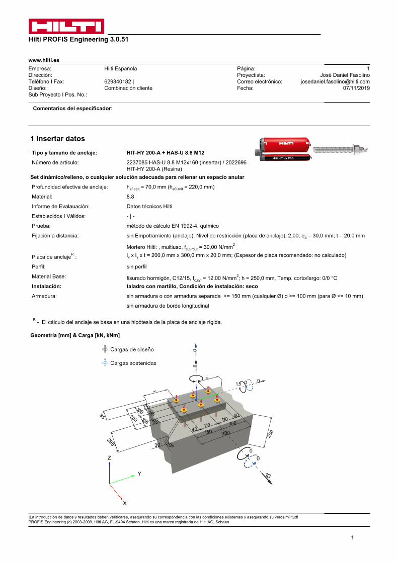
1 Insertar datos
Tipo y tamaño de anclaje: HIT-HY 200-A + HAS-U 8.8 M12
Número de artículo: 2237085 HAS-U 8.8 M12x160 (Insertar) / 2022696 HIT-HY 200-A (Resina)
Set dinámico/relleno, o cualquier solución adecuada para rellenar un espacio anular
Profundidad efectiva de anclaje: hef,opti = 70,0 mm (hef,limit = 220,0 mm)
Material: 8.8
Informe de Evalauación: Datos técnicos Hilti
Establecidos I Válidos: - | -
Prueba: método de cálculo EN 1992-4, químico
Fijación a distancia: sin Empotramiento (anclaje); Nivel de restricción (placa de anclaje): 2,00; eb = 30,0 mm; t = 20,0 mm
Mortero Hilti: , multiuso, fc,Grout = 30,00 N/mm2
Placa de anclajeR : lx x ly x t = 200,0 mm x 300,0 mm x 20,0 mm; (Espesor de placa recomendado: no calculado)
Perfil: sin perfil
Material Base: fisurado hormigón, C12/15, fc,cyl = 12,00 N/mm2; h = 250,0 mm, Temp. corto/largo: 0/0 °C Instalación: taladro con martillo, Condición de instalación: seco
Armadura: sin armadura o con armadura separada >= 150 mm (cualquier Ø) o >= 100 mm (para Ø <= 10 mm)
sin armadura de borde longitudinal
R - El cálculo del anclaje se basa en una hipótesis de la placa de anclaje rígida.
Geometría [mm] & Carga [kN, kNm]

www.hilti.es
Hilti PROFIS Engineering 3.0.51
¡La introducción de datos y resultados deben verificarse, asegurando su correspondencia con las condiciones existentes y asegurando su verosimilitud! PROFIS Engineering (c) 2003-2009, Hilti AG, FL-9494 Schaan. Hilti es una marca registrada de Hilti AG, Schaan
2
Empresa:Dirección:Teléfono I Fax:Diseño:Sub Proyecto I Pos. No.:
Hilti Española
629840182 | Combinación cliente
Página:Proyectista:Correo electrónico:Fecha:
2José Daniel Fasolino
[email protected]/11/2019
1.1 Combinación de cargas
Caso Descripción Fuerzas [kN] / Momentos [kNm] Sismo Fuego Max. Útil. Anclaje [%]1 Combinación cliente N = 0,000; Vx = 10,000; Vy = 0,000;
Mx = 0,000; My = 1,500; Mz = 0,000;Nsus = 0,000; Mx,sus = 0,000; My,sus = 0,000;
no no 55
2 Caso de carga/Resultante de cargas en los anclajesCaso de carga: Cargas de diseño
Reacciones en el anclaje [kN]Carga a tracción: (+Tracción, -Compresión)
Anclaje Carga a tracciónFuerza de cortante Cortante en x Cortante en y1 3,613 1,667 1,667 0,0002 0,096 1,667 1,667 0,0003 3,613 1,667 1,667 0,0004 0,096 1,667 1,667 0,0005 3,613 1,667 1,667 0,0006 0,096 1,667 1,667 0,000
Máxima extensión del hormigón a compresión: 0,07 [‰]Máxima tensión del hormigón a compresión: 2,00 [N/mm2]Tracción resultante en (x/y)=(-47,2/0,0): 11,126 [kN]Compresión resultante en (x/y)=(87,7/0,0): 11,126 [kN]
Las fuerzas del anclaje se calculan suponiendo que la placa base ofrece la rigidez correcta.
Tracción Compresión
1 2
3 4
5 6
x
y
www.hilti.es
Hilti PROFIS Engineering 3.0.51
¡La introducción de datos y resultados deben verificarse, asegurando su correspondencia con las condiciones existentes y asegurando su verosimilitud! PROFIS Engineering (c) 2003-2009, Hilti AG, FL-9494 Schaan. Hilti es una marca registrada de Hilti AG, Schaan
3
Empresa:Dirección:Teléfono I Fax:Diseño:Sub Proyecto I Pos. No.:
Hilti Española
629840182 | Combinación cliente
Página:Proyectista:Correo electrónico:Fecha:
3José Daniel Fasolino
[email protected]/11/2019
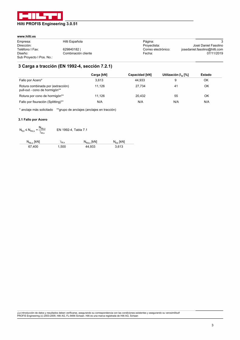
3 Carga a tracción (EN 1992-4, sección 7.2.1)
Carga [kN] Capacidad [kN] Utilización bN [%] Estado Fallo por Acero* 3,613 44,933 9 OK
Rotura combinada por (extracción) pull-out - cono de hormigón**
11,126 27,734 41 OK
Rotura por cono de hormigón** 11,126 20,432 55 OK
Fallo por fisuración (Splitting)** N/A N/A N/A N/A
* anclaje más solicitado **grupo de anclajes (anclajes en tracción)
3.1 Fallo por Acero
NEd ≤ NRd,s = NRk,sgM,s
EN 1992-4, Tabla 7.1
NRk,s [kN] gM,s NRd,s [kN] NEd [kN]67,400 1,500 44,933 3,613

www.hilti.es
Hilti PROFIS Engineering 3.0.51
¡La introducción de datos y resultados deben verificarse, asegurando su correspondencia con las condiciones existentes y asegurando su verosimilitud! PROFIS Engineering (c) 2003-2009, Hilti AG, FL-9494 Schaan. Hilti es una marca registrada de Hilti AG, Schaan
4
Empresa:Dirección:Teléfono I Fax:Diseño:Sub Proyecto I Pos. No.:
Hilti Española
629840182 | Combinación cliente
Página:Proyectista:Correo electrónico:Fecha:
4José Daniel Fasolino
[email protected]/11/2019
3.2 Rotura combinada por (extracción) pull-out - cono de hormigón
NEd ≤ NRd,p = NRk,pgM,p
EN 1992-4, Tabla 7.1
NRk,p = N0Rk,p ·
Ap,N
A0p,N
· y g,Np · y s,Np · y re,N · y ec1,Np · y ec2,Np EN 1992-4, Eq. (7.13)
N0Rk,p = y sus · t Rk · p · d · hef EN 1992-4, Eq. (7.14)
y sus = 1 EN 1992-4, Eq. (7.14a)
scr,Np = 7,3 · d · √y sus · t Rk ≤ 3 · hef EN 1992-4, Eq. (7.15)
y g,Np = y 0g,Np - ( sscr,Np
)0,5
· (y 0g,Np - 1) ≥ 1,00 EN 1992-4, Eq. (7.17)
y 0g,Np = √n - (√n - 1) · ( t Rkt Rk,c
)1,5
≥ 1,00 EN 1992-4, Eq. (7.18)
t Rk,c = k3
p · d · √hef · fck EN 1992-4, Eq. (7.19)
y s,Np = 0,7 + 0,3 · cccr,Np
≤ 1,00 EN 1992-4, Eq. (7.20)
y ec1,Np = 1
1 + (2 · ec1,Nscr,Np
) ≤ 1,00 EN 1992-4, Eq. (7.21)
y ec2,Np = 1
1 + (2 · ec2,Nscr,Np
) ≤ 1,00 EN 1992-4, Eq. (7.21)
Ap,N [mm2] A0p,N [mm2] t Rk,ucr,20 [N/mm2] scr,Np [mm] ccr,Np [mm] cmin [mm] fc,cyl [N/mm2]
133.300 44.100 18,00 210,0 105,0 95,0 12,00
y c t Rk,cr [N/mm2] k3 t Rk,c [N/mm2] y 0g,Np y g,Np
0,945 8,04 7,700 5,92 1,000 1,000
ec1,N [mm] y ec1,Np ec2,N [mm] y ec2,Np y s,Np y re,Np
52,2 0,668 0,0 1,000 0,971 1,000
y 0sus asus y sus
0,740 0,000 1,000
N0Rk,p [kN] NRk,p [kN] gM,p NRd,p [kN] NEd [kN]
21,205 41,601 1,500 27,734 11,126

www.hilti.es
Hilti PROFIS Engineering 3.0.51
¡La introducción de datos y resultados deben verificarse, asegurando su correspondencia con las condiciones existentes y asegurando su verosimilitud! PROFIS Engineering (c) 2003-2009, Hilti AG, FL-9494 Schaan. Hilti es una marca registrada de Hilti AG, Schaan
5
Empresa:Dirección:Teléfono I Fax:Diseño:Sub Proyecto I Pos. No.:
Hilti Española
629840182 | Combinación cliente
Página:Proyectista:Correo electrónico:Fecha:
5José Daniel Fasolino
[email protected]/11/2019
3.3 Rotura por cono de hormigón
NEd ≤ NRd,c = NRk,cgM,c
EN 1992-4, Tabla 7.1
NRk,c = N0Rk,c ·
Ac,N
A0c,N
· y s,N · y re,N · y ec1,N · y ec2,N · y M,N EN 1992-4, Eq. (7.1)
N0Rk,c = k1 · √fck · h
1,5ef EN 1992-4, Eq. (7.2)
A0c,N = scr,N · scr,N EN 1992-4, Eq. (7.3)
y s,N = 0,7 + 0,3 · cccr,N
≤ 1,00 EN 1992-4, Eq. (7.4)
y ec1,N = 1
1 + (2 · eN,1scr,N
) ≤ 1,00 EN 1992-4, Eq. (7.6)
y ec2,N = 1
1 + (2 · eN,2scr,N
) ≤ 1,00 EN 1992-4, Eq. (7.6)
y M,N = 1 EN 1992-4, Eq. (7.7)
Ac,N [mm2] A0c,N [mm2] ccr,N [mm] scr,N [mm] fc,cyl [N/mm2]
133.300 44.100 105,0 210,0 12,00
ec1,N [mm] y ec1,N ec2,N [mm] y ec2,N y s,N y re,N
52,2 0,668 0,0 1,000 0,971 1,000
z [mm] y M,N k1 N0Rk,c [kN] gM,c NRd,c [kN] NEd [kN]
134,8 1,000 7,700 15,622 1,500 20,432 11,126

www.hilti.es
Hilti PROFIS Engineering 3.0.51
¡La introducción de datos y resultados deben verificarse, asegurando su correspondencia con las condiciones existentes y asegurando su verosimilitud! PROFIS Engineering (c) 2003-2009, Hilti AG, FL-9494 Schaan. Hilti es una marca registrada de Hilti AG, Schaan
6
Empresa:Dirección:Teléfono I Fax:Diseño:Sub Proyecto I Pos. No.:
Hilti Española
629840182 | Combinación cliente
Página:Proyectista:Correo electrónico:Fecha:
6José Daniel Fasolino
[email protected]/11/2019
4 Carga de cortante (EN 1992-4, Sección 7.2.2)
Carga [kN] Capacidad [kN] Utilización bV [%] Estado Fallo por Acero (sin brazo de palanca)* 1,667 26,960 7 OK
Fallo por Acero (con brazo de palanca)* 1,667 3,352 50 OK
Fallo por desconchamiento** 10,000 61,160 17 OK
Rotura de borde de hormigón en dirección x+**
10,000 26,359 38 OK
* anclaje más solicitado **grupo de anclajes (anclajes relevantes)
4.1 Fallo por Acero (sin brazo de palanca)
VEd ≤ VRd,s = VRk,sgM,s
EN 1992-4, Tabla 7.2
VRk,s = k7 · V0Rk,s EN 1992-4, Eq. (7.35)
V0Rk,s [kN] k7 VRk,s [kN] gM,s VRd,s [kN] VEd [kN]
33,700 1,000 33,700 1,250 26,960 1,667
4.2 Fallo por Acero (con brazo de palanca)
VEd ≤ VRd,s,M = VRk,s,M
gM,s EN 1992-4, Tabla 7.2
VRk,s,M = aM · MRk,s
la EN 1992-4, Eq. 7.37
MRk,s = M0Rk,s · (1 -
NEdNRd,s
) EN 1992-4, Eq. 7.38
la = ec + t2 + a3 EN 1992-4, Eq. 6.2
l [mm] aM
46,0 2,00
NEd / NRd,s 1 - NEd / NRd,s M0Rk,s [kNm] MRk,s = M0
Rk,s (1 - NEd/NRd,s) [kNm]0,080 0,920 0,105 0,096
VMRk,s = aM * MRk,s / l [kN] gMs VM
Rd,s [kN] VEd [kN]4,190 1,250 3,352 1,667

www.hilti.es
Hilti PROFIS Engineering 3.0.51
¡La introducción de datos y resultados deben verificarse, asegurando su correspondencia con las condiciones existentes y asegurando su verosimilitud! PROFIS Engineering (c) 2003-2009, Hilti AG, FL-9494 Schaan. Hilti es una marca registrada de Hilti AG, Schaan
7
Empresa:Dirección:Teléfono I Fax:Diseño:Sub Proyecto I Pos. No.:
Hilti Española
629840182 | Combinación cliente
Página:Proyectista:Correo electrónico:Fecha:
7José Daniel Fasolino
[email protected]/11/2019
4.3 Fallo por desconchamiento (control resistencia por cono de hormigón)
VEd ≤ VRd,cp = VRk,cpgM,c,p
EN 1992-4, Tabla 7.2
VRk,cp = k8 · min {NRk,c; NRk,p} EN 1992-4, Eq. (7.39c)
NRk,c = N0Rk,c ·
Ac,N
A0c,N
· y s,N · y re,N · y ec1,N · y ec2,N · y M,N EN 1992-4, Eq. (7.1)
N0Rk,c = k1 · √fck · h
1,5ef EN 1992-4, Eq. (7.2)
A0c,N = scr,N · scr,N EN 1992-4, Eq. (7.3)
y s,N = 0,7 + 0,3 · cccr,N
≤ 1,00 EN 1992-4, Eq. (7.4)
y ec1,N = 1
1 + (2 · eV,1scr,N
) ≤ 1,00 EN 1992-4, Eq. (7.6)
y ec2,N = 1
1 + (2 · eV,2scr,N
) ≤ 1,00 EN 1992-4, Eq. (7.6)
y M,N = 1 EN 1992-4, Eq. (7.7)
Ac,N [mm2] A0c,N [mm2] ccr,N [mm] scr,N [mm] k8 fc,cyl [N/mm2]
133.300 44.100 105,0 210,0 2,000 12,00
ec1,V [mm] y ec1,N ec2,V [mm] y ec2,N y s,N y re,N y M,N
0,0 1,000 0,0 1,000 0,971 1,000 1,000
k1 N0Rk,c [kN] gM,c,p VRd,cp [kN] VEd [kN]
7,700 15,622 1,500 61,160 10,000
www.hilti.es
Hilti PROFIS Engineering 3.0.51
¡La introducción de datos y resultados deben verificarse, asegurando su correspondencia con las condiciones existentes y asegurando su verosimilitud! PROFIS Engineering (c) 2003-2009, Hilti AG, FL-9494 Schaan. Hilti es una marca registrada de Hilti AG, Schaan
8
Empresa:Dirección:Teléfono I Fax:Diseño:Sub Proyecto I Pos. No.:
Hilti Española
629840182 | Combinación cliente
Página:Proyectista:Correo electrónico:Fecha:
8José Daniel Fasolino
[email protected]/11/2019
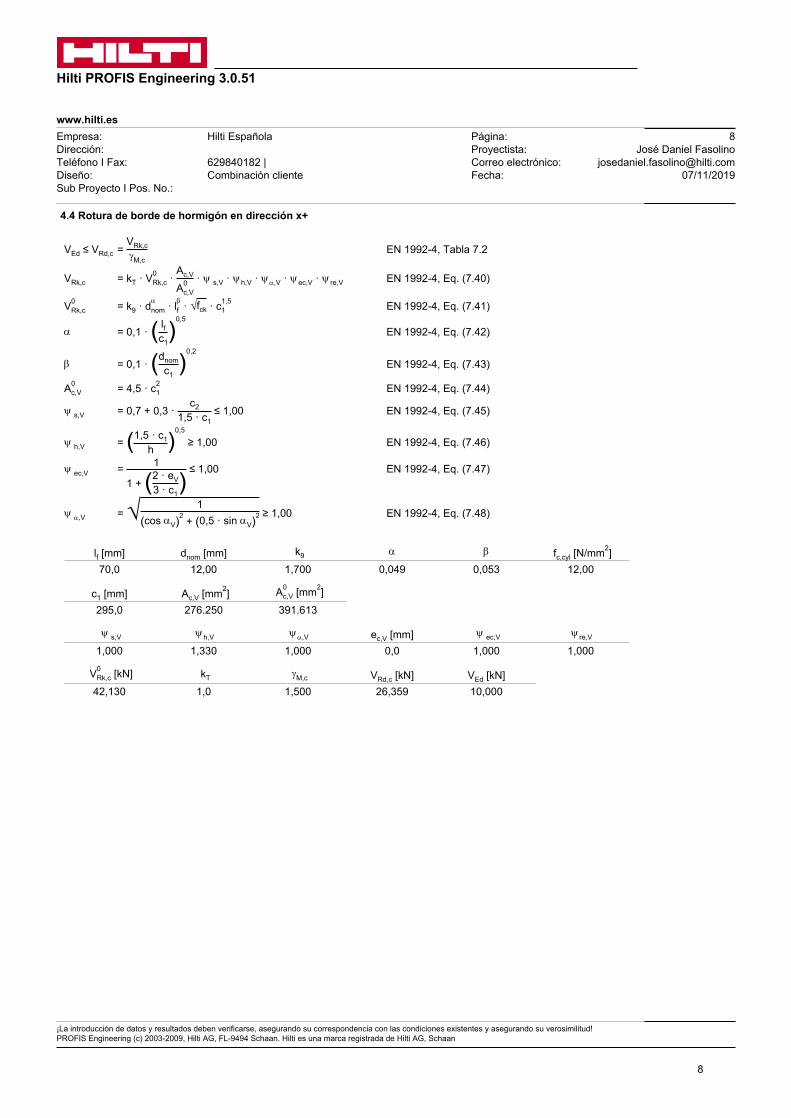
4.4 Rotura de borde de hormigón en dirección x+
VEd ≤ VRd,c = VRk,cgM,c
EN 1992-4, Tabla 7.2
VRk,c = kT · V0Rk,c ·
Ac,V
A0c,V
· y s,V · y h,V · y a,V · y ec,V · y re,V EN 1992-4, Eq. (7.40)
V0Rk,c = k9 · d
anom · lbf · √fck · c
1,51 EN 1992-4, Eq. (7.41)
a = 0,1 · ( lfc1)
0,5
EN 1992-4, Eq. (7.42)
b = 0,1 · (dnomc1
)0,2
EN 1992-4, Eq. (7.43)
A0c,V = 4,5 · c2
1 EN 1992-4, Eq. (7.44)
y s,V = 0,7 + 0,3 · c2
1,5 · c1 ≤ 1,00 EN 1992-4, Eq. (7.45)
y h,V = (1,5 · c1h )
0,5
≥ 1,00 EN 1992-4, Eq. (7.46)
y ec,V = 1
1 + (2 · eV3 · c1
) ≤ 1,00 EN 1992-4, Eq. (7.47)
y a,V = √ 1(cos aV)2 + (0,5 · sin aV)2 ≥ 1,00 EN 1992-4, Eq. (7.48)
lf [mm] dnom [mm] k9 a b fc,cyl [N/mm2]70,0 12,00 1,700 0,049 0,053 12,00
c1 [mm] Ac,V [mm2] A0c,V [mm2]
295,0 276.250 391.613
y s,V y h,V y a,V ec,V [mm] y ec,V y re,V
1,000 1,330 1,000 0,0 1,000 1,000
V0Rk,c [kN] kT gM,c VRd,c [kN] VEd [kN]
42,130 1,0 1,500 26,359 10,000

www.hilti.es
Hilti PROFIS Engineering 3.0.51
¡La introducción de datos y resultados deben verificarse, asegurando su correspondencia con las condiciones existentes y asegurando su verosimilitud! PROFIS Engineering (c) 2003-2009, Hilti AG, FL-9494 Schaan. Hilti es una marca registrada de Hilti AG, Schaan
9
Empresa:Dirección:Teléfono I Fax:Diseño:Sub Proyecto I Pos. No.:
Hilti Española
629840182 | Combinación cliente
Página:Proyectista:Correo electrónico:Fecha:
9José Daniel Fasolino
[email protected]/11/2019
5 Cargas combinadas de tracción y cortante ( EN 1992-4, Sección 7.2.3)Fallo del acero
bN bV a Utilización bN,V [%] Estado0,080 0,062 2,000 2 OK
baN + ba
V ≤ 1,0
Fallo del hormigón
bN bV a Utilización bN,V [%] Estado0,545 0,379 1,500 64 OK
baN + ba
V ≤ 1,0
6 Desplazamientos (anclaje más solicitado)Cargas de corto plazo:
NSk = 0,071 [kN] dN = 0,0019 [mm]
VSk = 2,469 [kN] dV = 0,1235 [mm]
dNV = 0,1235 [mm]Carga de largo plazo:
NSk = 0,071 [kN] dN = 0,0043 [mm]
VSk = 2,469 [kN] dV = 0,1975 [mm]
dNV = 0,1976 [mm]
Comentarios: Desplazamientos a tracción son válidos con la mitad del par de apriete requerido no fisurado ¡Hormigón! Los desplazamientos son validos sin rozamiento entre el hormigón y la placa de anclaje! La holgura entre el taladro en el hormigón y en la placa no son considerados en este cálculo.
¡Los desplazamientos aceptables en los anclajes dependen del tipo de construcción de la fijación y deben ser definidos por el proyectista!

www.hilti.es
Hilti PROFIS Engineering 3.0.51
¡La introducción de datos y resultados deben verificarse, asegurando su correspondencia con las condiciones existentes y asegurando su verosimilitud! PROFIS Engineering (c) 2003-2009, Hilti AG, FL-9494 Schaan. Hilti es una marca registrada de Hilti AG, Schaan
10
Empresa:Dirección:Teléfono I Fax:Diseño:Sub Proyecto I Pos. No.:
Hilti Española
629840182 | Combinación cliente
Página:Proyectista:Correo electrónico:Fecha:
10José Daniel Fasolino
[email protected]/11/2019
7 Avisos• No se considera la redistribución de carga entre los aclajes debido a deformaciones elasticas de la placa. ¡Se asume que la placa es
suficientemente rígida, para evitar que se deforme cuando se somete a cargas! ¡Los datos de entrada y resultados deben ser comprobados para verificar que se encuentran conformes con las condiciones existentes y que sean admisible!
• ¡Verificación de la tranferencia de cargas al material base es necesaria según fiEN 1992-4, Anexo A!
• ¡El diseño solo es válido si la holgura en la instalación no es mayor que los valores dados en la Tabla 6.1 de la EN 1992-4! Para holguras mayores ver sección 6.2.2 de la EN 1992-4!
• La lista de accesorios en este informe es sólo para información del usuario. En cualquier caso, las instrucciones para el uso, mostrados en el producto, deben ser seguidas para asegurar una correcta instalación.
• Para la determinación del \ raw {\ psi {} _ {re, v}} (fallo de borde de hormigón) se asume un recubrimiento de hormigón en la armadura de refurzo de borde de c = 30 mm
• El taladro debe limpiarse de acuerdo con la homologación (soplar dos veces con aire comprimido (min. 6 bar), cepillar dos veces y volver a soplar dos veces con aire comprimido (min. 6 bar)).
• La tensión de adherencia característica depende de las temperaturas de corto y largo plazo
• No se requiere armadura de borde para evitar rotura por splitting
• Design is only valid if hole is filled to remove clearance, clearance as per EN 1992-4 Table 6.1
¡La fijación cumple los criterios de diseño!

www.hilti.es
Hilti PROFIS Engineering 3.0.51
¡La introducción de datos y resultados deben verificarse, asegurando su correspondencia con las condiciones existentes y asegurando su verosimilitud! PROFIS Engineering (c) 2003-2009, Hilti AG, FL-9494 Schaan. Hilti es una marca registrada de Hilti AG, Schaan
11
Empresa:Dirección:Teléfono I Fax:Diseño:Sub Proyecto I Pos. No.:
Hilti Española
629840182 | Combinación cliente
Página:Proyectista:Correo electrónico:Fecha:
11José Daniel Fasolino
[email protected]/11/2019
Coordenadas del anclaje mm
Anclaje x y c-x c+x c-y c+y
1 -50,0 -110,0 95,0 405,0 - -2 60,0 -110,0 205,0 295,0 - -3 -50,0 0,0 95,0 405,0 - -
Anclaje x y c-x c+x c-y c+y
4 60,0 0,0 205,0 295,0 - -5 -50,0 110,0 95,0 405,0 - -6 60,0 110,0 205,0 295,0 - -
8 Datos de instalación
Placa de anclaje, acero: S 235; E = 210.000,00 N/mm2; fyk = 235,00 N/mm2 Tipo y tamaño de anclaje: HIT-HY 200-A + HAS-U 8.8 M12
Perfil: sin perfil Número de artículo: 2237085 HAS-U 8.8 M12x160 (Insertar) / 2022696 HIT-HY 200-A (Resina)
Diámetro de taladro en chapa: df = 14,0 mm Par de apriete de instalación: 40 Nm Espesor de placa (introducir): 20,0 mm Diámetro de taladro en material base: 14,0 mm Espesor de placa recomendado: no calculado Profundidad de taladro (min/max): 70,0 mm Método de perforación: Taladro a rotopercusión Mínimo espesor del material base: 100,0 mm Limpieza: Se requiere limpieza del taladro con aire comprimido.
Hilti HIT-V varilla roscada con HIT-HY 200 resina de inyección con 70 mm de empotramiento, M12, Acero Galvanizado, instalado mediante Taladro a percusión, según instrucciones de uso , con relleno de taladro mediante Set dinámico Hilti u otra solución adecuada
8.1 Accesorios recomendados
Taladro Limpieza Instalación• Taladro a rotopercusión adecuado• Tamaño adecuado de broca
• Aire comprimido con los accesorios requeridos para soplar desde el fondo del taladro.
• Diámetro adecuado de cepillo de alambre
• El sistema de inyección incluye el mezclador y porta-cartuchos
• Llave dinamométrica
1 2
3 4
5 6
50,0 110,0 40,0
40,0
110,
011
0,0
40,0
x
y100,0 100,0
150,
015
0,0

www.hilti.es
Hilti PROFIS Engineering 3.0.51
¡La introducción de datos y resultados deben verificarse, asegurando su correspondencia con las condiciones existentes y asegurando su verosimilitud! PROFIS Engineering (c) 2003-2009, Hilti AG, FL-9494 Schaan. Hilti es una marca registrada de Hilti AG, Schaan
12
Empresa:Dirección:Teléfono I Fax:Diseño:Sub Proyecto I Pos. No.:
Hilti Española
629840182 | Combinación cliente
Página:Proyectista:Correo electrónico:Fecha:
12José Daniel Fasolino
[email protected]/11/2019
9 Observaciones; comentarios• Toda la información y todos los datos contenidos en el software sólo se refieren a la utilización de los productos Hilti y están fundados en
principios, fórmulas y normativas de seguridad conformes a las consignas técnicas de Hilti y en instrucciones de operación, montaje, ensamblaje, etc., que el usuario debe seguir exhaustivamente. Todas las cifras que en ellos constan son medias; por lo tanto, se deben realizar pruebas específicas de utilización antes de la utilización del producto Hilti aplicable. Los resultados de los cálculos ejecutados mediante el software reposan básicamente en los datos que usted introduce en el mismo. Por lo tanto, es usted el único responsable de la inexistencia de errores, de le exhaustividad y la pertinencia de los datos introducidos por usted mismo. Asimismo, es usted el único responsable de la verificación de los resultados del cálculo y de la validación de los mismos por un experto, en especial en lo referente al cumplimiento de las normas y permisos aplicables previamente a su utilización, en particular para su aplicación. El software sólo sirve de ayuda para la interpretación de las normas y permisos sin ninguna garantía con respecto a la ausencia de errores, la exactitud y la pertinencia de los resultados o su adaptación a una determinada aplicación.
• Debe usted tomar todas las medidas necesarias y razonables para impedir o limitar los daños causados por el software. En especial, debe usted tomar sus disposiciones para efectuar regularmente un copia de seguridad de los programas y de los datos y, de ser aplicable, ejecutar las actualizaciones regularmente facilitadas por Hilti. Si no utiliza la función AutoUpdate del software, debe usted comprobar que en cada caso usted utiliza la versión actual y puesta al día del software, ejecutando actualizaciones manuales a través del Sitio Web Hilti. Hilti no será considerada como responsable por cualquier consecuencia, tal y como la necesidad de recuperar necesidades o programas perdidos o dañados, que se deriven de un incumplimiento, por su parte, de sus obligaciones.

MaaB arquitectura y urbanismo slp ANEXO I JUSTIFICACIÓN CTE
C/Tristan de Leguizamon 1, bajo - 48007 Bilbao - 94 423 18 37 - [email protected]
REHABILITACION ENVOLVENTE TERMICA EDIFICIO DE VIVIENDAS. ARTAZAGANE 45. LEIOA 8
1.2. CÁLCULO DE LOS PANELES Y GANCHOS DE SUJECIÓN
La estabilidad de los propios paneles y del gancho de cuelgue ha sido analizada por el
consorcio RENOZEB en el documento que se presenta a continuación.

Via Giovanni Pascoli, 39 – 47822 Santarcangelo di Romagna (RN) Italy - T. (+39) 0541623329 - Email: [email protected]
www.meweng.com
Santarcangelo di Romagna,December 2, 2019
Voru (EW) – Durango (E)
R03 - Units
PROJECT: RenoZeb 000038
Voru, Estonia / Durango, Spain
CLIENT: Focchi S.p.a.
Via Cornacchiara, 805 – 47824 Poggio Torriana [Italy]
STRUCTURAL DESIGNER: Eng. Odine MANFRONI
R03 - UNITS RENOZEB
2
Index Introduction ................................................................................................................................................................. 3
1. References ........................................................................................................................................................... 6
2. Material Properties .......................................................................................................................................... 7
2.1 Aluminum EN AW 6063T6 .................................................................................................................... 7
2.2 Steel S355 .................................................................................................................................................... 7
2.3 Polyamide PA 66 GF25 ........................................................................................................................... 8
2.4 Bolts ............................................................................................................................................................... 9
2.5 Screws ......................................................................................................................................................... 10
3. UNIT CHECK ..................................................................................................................................................... 11
3.1 Mullion check ........................................................................................................................................... 11
3.1.1 Stress check ...................................................................................................................................... 18
3.1.2 Deflection check ............................................................................................................................. 20
3.2 Transoms check....................................................................................................................................... 21
3.2.1 Sections .............................................................................................................................................. 22
3.2.2 Lower and upper transoms ........................................................................................................ 32
3.2.3 Central transom .............................................................................................................................. 42
3.3 Local Analysis – Connections check ................................................................................................ 47
3.3.1 Stack Joint Connection ................................................................................................................. 48
3.3.2 Female transom .............................................................................................................................. 50
3.3.3 Central transom Connection ...................................................................................................... 52
3.4 Durango – Connection to the existing structure ......................................................................... 55
3.4.1 Hook-on Bracket ............................................................................................................................ 55
3.4.2 Double ‘C’ aluminum bracket .................................................................................................... 61
3.4.3 Connection to the concrete slab ............................................................................................... 65
4. Annex A ............................................................................................................................................................... 69

R03 - UNITS RENOZEB
3
Introduction The following report analyzes the units to be installed on two similar facades in two different cities: one in Voru (Estonia) and on in Durango (Spain).
Figure 1 Top view
Figure 2 Lateral view

R03 - UNITS RENOZEB
4
In the following, the biggest unit is analyzed; main dimensions are the following.
Unit Dimensions
2200x3000 [mm] Table 1 Unit dimensions
Figure 3 Vertical section
The external loads are applied according with the load combinations shown in report R01.
Lower Transom
Central Transom
Upper Transom

R03 - UNITS RENOZEB
5
Figure 4 Loads application
Dead Load
Wind Positive/Negative
Pressure
Live Load

R03 - UNITS RENOZEB
6
1. References In drawing up these calculations, reference has been made to the laws and current Technical standard in force as given below:
- UNI ENV 1991-2-1: 2005 “Eurocode 1: actions on structures”
- UNI ENV 1991-2-4: 2005 “Eurocode 1: wind action on structures”
- UNI/TR 11463 - EN 14024:2004
- Technical Update 14 – Window and Cladding “Load Combinations”
R03 - UNITS RENOZEB
7
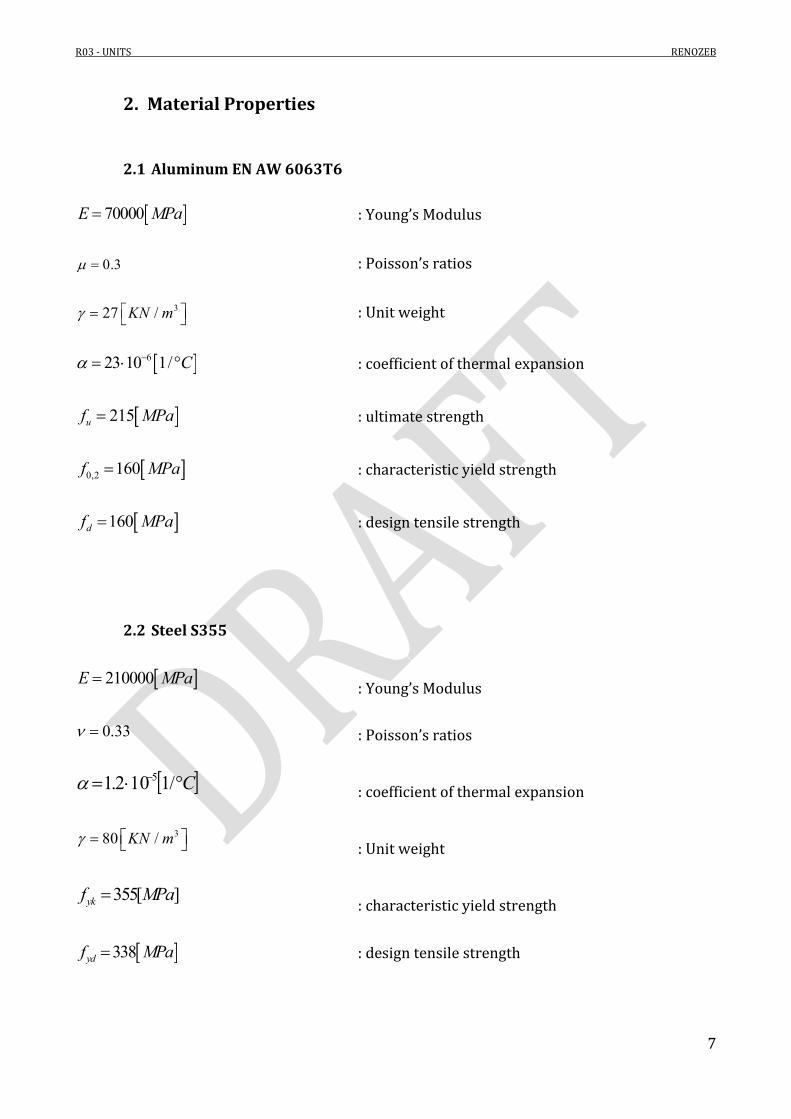
2. Material Properties
2.1 Aluminum EN AW 6063T6
70000E MPa : Young’s Modulus
0.3 : Poisson’s ratios
327 /KN m : Unit weight
623 10 1/ C : coefficient of thermal expansion
215uf MPa : ultimate strength
0,2 160f MPa : characteristic yield strength
160df MPa : design tensile strength
2.2 Steel S355
210000E MPa : Young’s Modulus
0.33 : Poisson’s ratios
C /1102.1 5 : coefficient of thermal expansion
380 /KN m : Unit weight
355[ ]ykf MPa : characteristic yield strength
338ydf MPa : design tensile strength

R03 - UNITS RENOZEB
8
2.3 Polyamide PA 66 GF25
Table 2 Polyamide mechanical properties

R03 - UNITS RENOZEB
9
2.4 Bolts Resistance class = 8.8
649ybf MPa : yield strength
800tbf MPa : breaking strength
Shear and tensile strength of the bolts is evaluated in accordance with the Eurocodes, as follows. Shear Resistance
,
0.6 ub resv Rd
Mb
f AF
Tensile resistance
,
0.9 ub rest Rd
Mb
f AF
Bolt Fvrd [kN]
Ftrd [kN]
M10 22 33 M12 32 48
Table 3 Bolts strength

R03 - UNITS RENOZEB
10
2.5 Screws Resistance class = 8.8
649ybf MPa : yield strength
800tbf MPa : breaking strength
Shear and tensile strength of the bolts is evaluated in accordance with the Eurocodes, as follows. Shear Resistance
,
0.6 ub resv Rd
Mb
f AF
Tensile resistance
,
0.9 ub rest Rd
Mb
f AF
Bolt Fvrd [kN]
Ftrd [kN]
Φ6.3 8.9 13.5 Table 4 Screws strength

R03 - UNITS RENOZEB
11
3. UNIT CHECK
3.1 Mullion check The unit has two mullions with the same symmetric section. In the following, a single mullion is analyzed.
Figure 5 Top view
Mullion

R03 - UNITS RENOZEB
12
Figure 6 Lateral view

R03 - UNITS RENOZEB
13
The inertia value of the profile (single mullion) is determined according with code EN 14024:2004. The code specifies the method to evaluate the mechanical performance of a profile with thermal barrier. The formulas are shown in the following.

R03 - UNITS RENOZEB
14
Figure 7 Effective momentum of inertia of thermal barrier profiles.
Figure 8 Female transom section
Profile 1
Profile 2

R03 - UNITS RENOZEB
15
Profile 1 (P1) area A 4.77 cm2
inertia Jy 21.23 cm4 Center to center distance x 6.8 cm
Table 5 Profile 1
Profile 2 (P2) area A 7.61 cm2
inertia Jy 96.75 cm4 Center to center distance X 4.26 cm
Table 6 Profile 2
PA66 GF25 Young’s modulus E 1300 MPa
Thickness th 0.16 cm Width w 3.6 cm Length l 300 cm
Table 7 Thermal break
4476[ ]J cm (Rigid moment of inertia)
0.752
(Compound part of the rigid moment of inertia) 5.84
0.776 1C
(measure of the effect of the elastic connection)
4283[ ]efJ cm (Rigid moment of inertia)
/ 0.59efJ J

R03 - UNITS RENOZEB
16
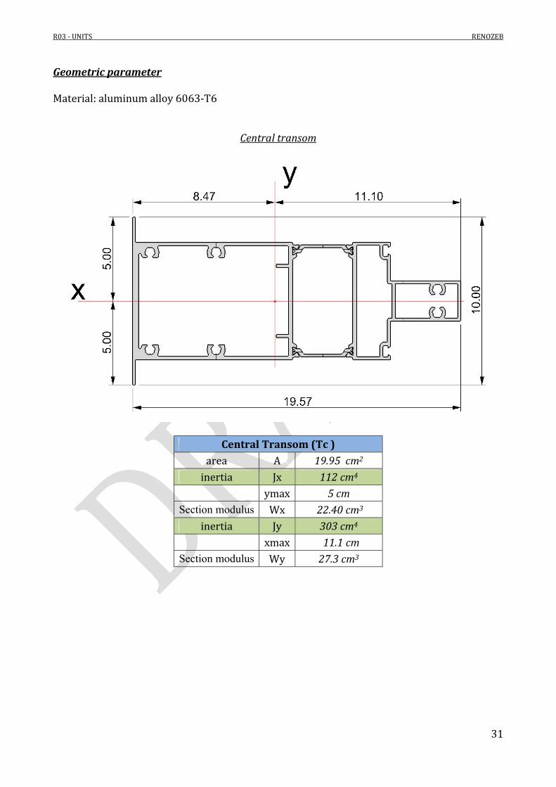
Geometric parameter Material: aluminum alloy 6063-T6
Mullion
Mullion (M) area A 12.38 cm2
inertia Jx 283 cm4 ymax 10.55 cm
Section modulus Wx 26.82 cm3

R03 - UNITS RENOZEB
17
The vertical mullion could be analyzed with a simple scheme, shown in the following.
Figure 9 Static scheme
Where:
2200[ ] / 2 1100[mm]b mm
21.55[kN/ ]windW m (design maximum
pressure, see report R01 – Loads)
0.5[ / ]kF kN m (Live load, see report R01 - Loads)
21.55[ / ] 1.1 1.70[ / ]windq W b kN m kN m
0.5[ / ] 1.1 0.55[ ]kF F b kN m kN
R03 - UNITS RENOZEB
18
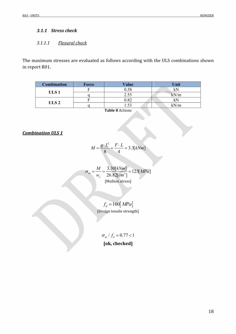
3.1.1 Stress check
3.1.1.1 Flexural check The maximum stresses are evaluated as follows according with the ULS combinations shown in report R01.
Combination Force Value Unit
ULS 1 F 0.58 kN
q 2.55 kN/m
ULS 2 F 0.82 kN q 1.53 kN/m
Table 8 Actions
Combination ULS 1
2
3.3[ ]8 4
q L F LM kNm
3
3.30[ ]123[ ]
26.82[ ]mx
M kNmMPa
w cm
[Mullion stress]
160df MPa
[Design tensile strength]
/ 0.77 1m df [ok, checked]

R03 - UNITS RENOZEB
19
Combination ULS 2
2
2.35[ ]8 4
q L F LM kNm
3
2.35[ ]87[ ]
26.82[ ]mx
M kNmMPa
w cm
[Mullion stress]
160df MPa
[Design tensile strength]
/ 0.55 1m df [ok, checked]

R03 - UNITS RENOZEB
20
3.1.2 Deflection check Deflection of the mullion is evaluated with the static scheme adopted for the stress check (see Figure 9). Deflection is evaluated in accordance with the SLS combinations shown in report R01.
Combination Force Value Unit
SLS 1 F 0.39 kN
q 1.70 kN/m
SLS 2 F 0.55 kN q 1.02 kN/m
Table 9 Actions
Combination SLS 1
4 35 110.1[ ]
384 48
q L F Lf mm
EJ EJ
max / 200 3000 / 200 15[ ]f H mm
maxf f [ok, checked]
Combination SLS 2
4 35 17.00[ ]
384 48
q L F Lf mm
EJ EJ
max / 200 3000 / 200 15[ ]f H mm
maxf f [ok, checked]

R03 - UNITS RENOZEB
21
3.2 Transoms check In the following, the three transoms are checked. Geometry and main features are as follows.
Figure 10 Vertical section
Female Transom
Central Transom
Male Transom
R03 - UNITS RENOZEB
22
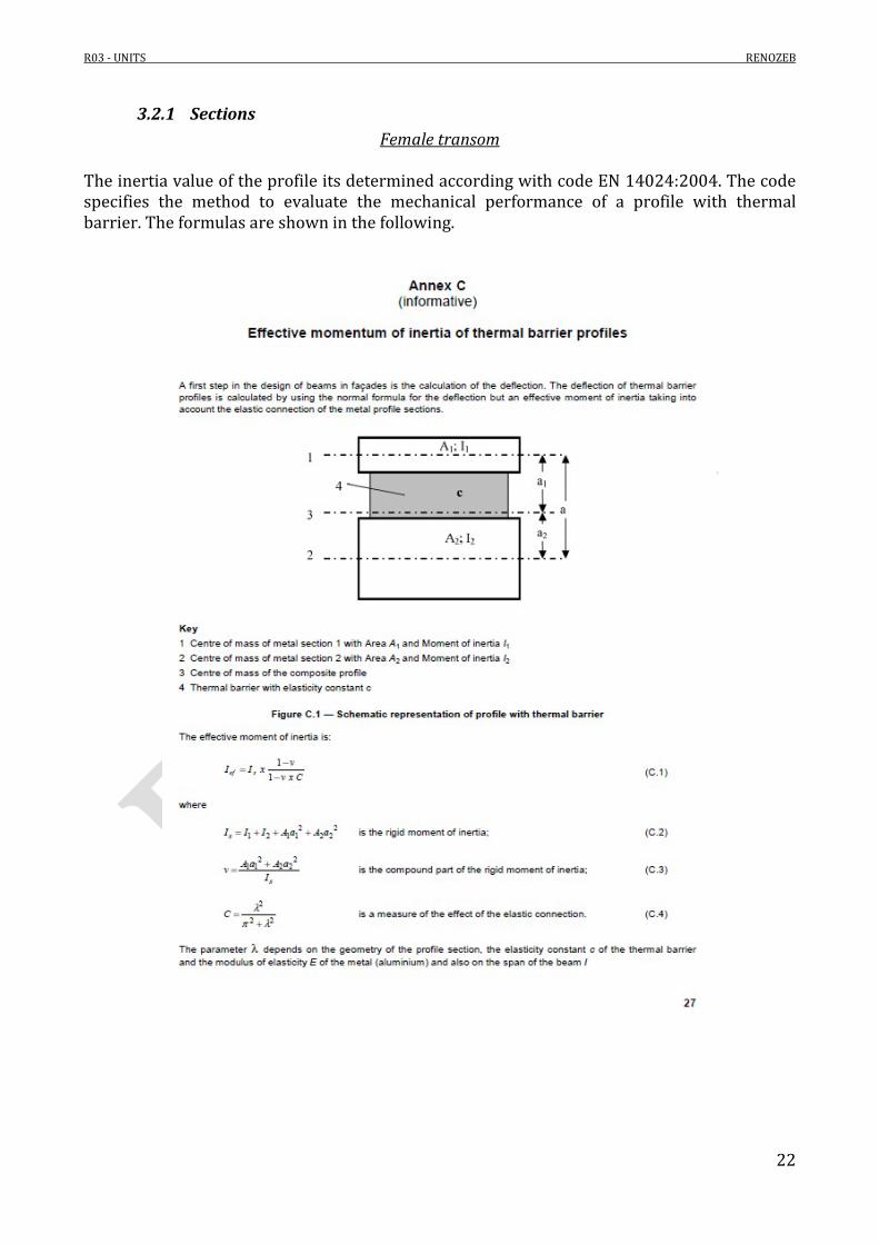
3.2.1 Sections Female transom
The inertia value of the profile its determined according with code EN 14024:2004. The code specifies the method to evaluate the mechanical performance of a profile with thermal barrier. The formulas are shown in the following.

R03 - UNITS RENOZEB
23
Figure 11 Effective momentum of inertia of thermal barrier profiles.
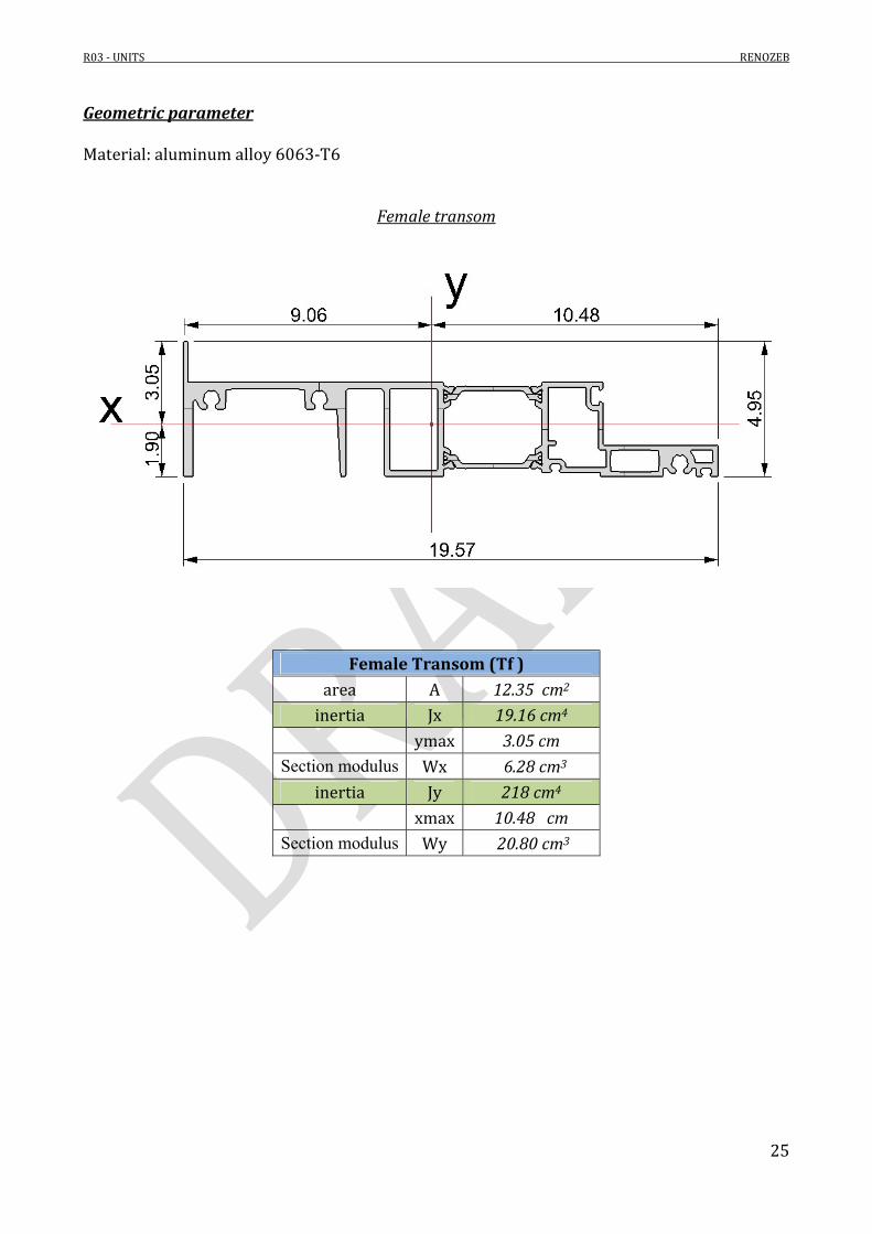
Figure 12 Female transom section
Profile 1 (P1)
area A 4.77 cm2 inertia Jy 21.23 cm4
Center to center distance x 6.73 cm Table 10 Profile 1
Profile 2 (P2) area A 7.58 cm2
inertia Jy 85.85 cm4 Center to center distance X 4.24 cm
Table 11 Profile 2
Profile 1 Profile 2

R03 - UNITS RENOZEB
24
PA66 GF25
Young’s modulus E 1300 MPa Thickness th 0.16 cm
Width w 3.6 cm Length l 220 cm
Table 12 Thermal break
4459[ ]J cm (Rigid moment of inertia)
0.767
(Compound part of the rigid moment of inertia) 4.42
0.664 1C
(measure of the effect of the elastic connection)
4218[ ]efJ cm (Rigid moment of inertia)
/ 0.47efJ J
R03 - UNITS RENOZEB
25
Geometric parameter Material: aluminum alloy 6063-T6
Female transom
Female Transom (Tf ) area A 12.35 cm2
inertia Jx 19.16 cm4 ymax 3.05 cm
Section modulus Wx 6.28 cm3 inertia Jy 218 cm4
xmax 10.48 cm Section modulus Wy 20.80 cm3
R03 - UNITS RENOZEB
26
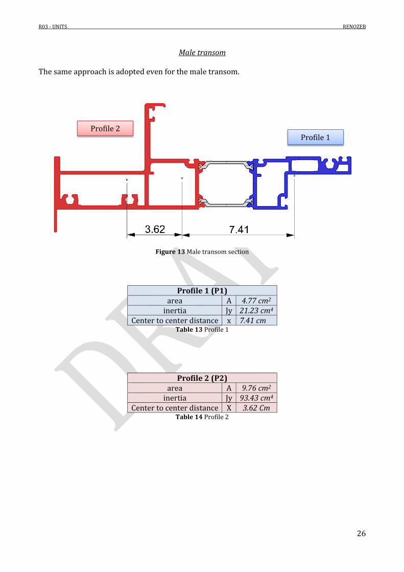
Male transom
The same approach is adopted even for the male transom.
Figure 13 Male transom section
Profile 1 (P1)
area A 4.77 cm2 inertia Jy 21.23 cm4
Center to center distance x 7.41 cm Table 13 Profile 1
Profile 2 (P2) area A 9.76 cm2
inertia Jy 93.43 cm4 Center to center distance X 3.62 Cm
Table 14 Profile 2
Profile 1 Profile 2

R03 - UNITS RENOZEB
27
PA66 GF25
Young’s modulus E 1300 MPa Thickness th 0.16 cm
Width w 3.60 cm Length l 220 cm
Table 15 Thermal break
4504[ ]J cm (Rigid moment of inertia)
0.773
(Compound part of the rigid moment of inertia) 4.28
0.649 1C
(measure of the effect of the elastic connection)
4230[ ]efJ cm (Rigid moment of inertia)
/ 0.45efJ J

R03 - UNITS RENOZEB
28
Geometric parameter Material: aluminum alloy 6063-T6
Male transom
Male Transom (Tm ) area A 14.53 cm2
inertia Jx 39.63 cm4 ymax 4.92 cm
Section modulus Wx 8.05 cm3 inertia Jy 230 cm4
xmax 11.15 cm Section modulus Wy 20.62 cm3
In the following, the global inertia of the two assembled transoms is evaluated.
458.79[ ]tot f mx x xJ J J cm
4448[ ]tot f m
yy yy yyJ J J cm

R03 - UNITS RENOZEB
29
Central transom The same approach is adopted even for the central transom.
Figure 14 Central transom section
Profile 1 (P1)
area A 6.45 cm2 inertia Jy 29.49 cm4
Center to center distance x 7.11 cm Table 16 Profile 1
Profile 2 (P2) area A 10.5 cm2
inertia Jy 141 cm4 Center to center distance X 4.37 cm
Table 17 Profile 2
Profile 1
Profile 2

R03 - UNITS RENOZEB
30
PA66 GF25
Young’s modulus E 1300 MPa Thickness th 0.16 cm
Width w 3.60 cm Length l 220 cm
Table 18 Thermal break
4697[ ]J cm (Rigid moment of inertia)
0.755
(Compound part of the rigid moment of inertia) 3.69
0.580 1C
(measure of the effect of the elastic connection)
4303[ ]efJ cm (Rigid moment of inertia)
/ 0.43efJ J
R03 - UNITS RENOZEB
31
Geometric parameter Material: aluminum alloy 6063-T6
Central transom
Central Transom (Tc ) area A 19.95 cm2
inertia Jx 112 cm4 ymax 5 cm
Section modulus Wx 22.40 cm3 inertia Jy 303 cm4
xmax 11.1 cm Section modulus Wy 27.3 cm3

R03 - UNITS RENOZEB
32
3.2.2 Lower and upper transoms Lower and upper transoms (female and male) are loaded by the wind pressure/sunction.
Figure 15 Female transom
Figure 16 Male transom

R03 - UNITS RENOZEB
33
The following simple static scheme is used in order to analyze the transom
Figure 17 Static scheme
The uniform load ‘q’ is proportional to the influence load area on the transom. In particular the load distribution could be assumed as shown in the following figure.

R03 - UNITS RENOZEB
34
Figure 18 Load distribution
2 21 2( ) 1.55[ / ] 2.04[ ] 1.45[ / ]2.20
windW W W kN m mq kN mb

R03 - UNITS RENOZEB
35
3.2.2.1 Stress check
3.2.2.1.1 Flexural check – Wind load The maximum stresses are evaluated as follows according with the ULS combinations shown in report R01.
Combination Force Value Unit
ULS 1 q 2.2 kN/m
Table 19 Transom
2 22.2[ / ] 2.201.35[kNm]
8 8
q b kN mM
Combination ULS 1 – Female profile
4
3 4
1.35[ ] 218[ ]32[ ]
20.8[ ] 448[ ]
fy y
f y f m fy y y
M J kNm cmMPa
w J J cm cm
[Female mullion stress]
160df MPa
[Design tensile strength]
/ 0.20 1f y df [ok, checked]
R03 - UNITS RENOZEB
36
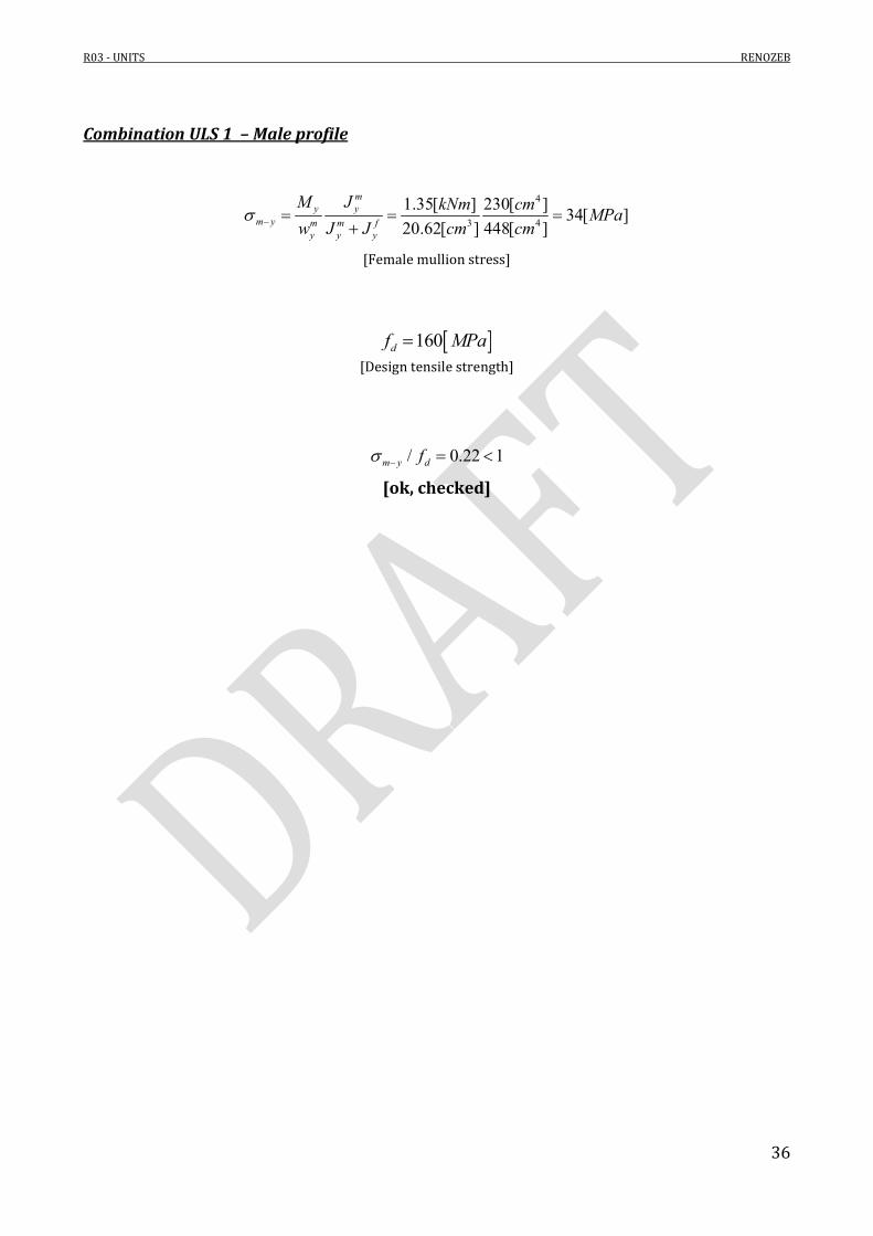
Combination ULS 1 – Male profile
4
3 4
1.35[ ] 230[ ]34[ ]
20.62[ ] 448[ ]
my y
m y m m fy y y
M J kNm cmMPa
w J J cm cm
[Female mullion stress]
160df MPa
[Design tensile strength]
/ 0.22 1m y df
[ok, checked]
R03 - UNITS RENOZEB
37
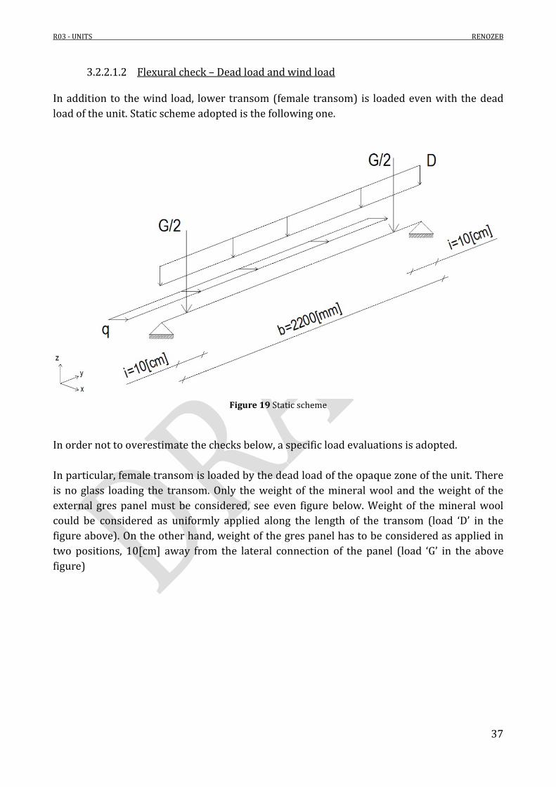
3.2.2.1.2 Flexural check – Dead load and wind load In addition to the wind load, lower transom (female transom) is loaded even with the dead load of the unit. Static scheme adopted is the following one.
Figure 19 Static scheme
In order not to overestimate the checks below, a specific load evaluations is adopted. In particular, female transom is loaded by the dead load of the opaque zone of the unit. There is no glass loading the transom. Only the weight of the mineral wool and the weight of the external gres panel must be considered, see even figure below. Weight of the mineral wool could be considered as uniformly applied along the length of the transom (load ‘D’ in the figure above). On the other hand, weight of the gres panel has to be considered as applied in two positions, 10[cm] away from the lateral connection of the panel (load ‘G’ in the above figure)
R03 - UNITS RENOZEB
38
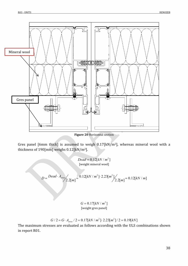
Figure 20 Horizontal section
Gres panel [6mm thick] is assumed to weigh 0.17[kN/m2], whereas mineral wool with a thickness of 190[mm] weighs 0.12[kN/m2].
20.12[ / ]Dead kN m
[weight mineral wool]
2 20.12[ / ] 2.23[ ] 0.12[ / ]2.2[ ] 2.2[ ]areaDead A kN m mD kN mm m
20.17[ / ]G kN m [weight gres panel]
2 2/ 2 / 2 0.17[ / ] 2.23[ ] / 2 0.19[ ]areaG G A kN m m kN
The maximum stresses are evaluated as follows according with the ULS combinations shown in report R01.
Gres panel
Mineral wool

R03 - UNITS RENOZEB
39
Combination Force Value Unit
ULS 1
q 2.2 kN/m
D 0.16 kN/m
G/2 0.25 kN
Table 20 Transom
Flexural moment due to the vertical loads is as follows.
0.15[kNm]xM
Combination ULS 1 – Female profile
max 3
0.15[ ]32[ ] 56[ ]
6.28[ ]x
f f y fx
M kNmMPa MPa
w cm
.
[Female mullion stress]
160df MPa
[Design tensile strength]
/ 0.51 1m df [ok, checked]
R03 - UNITS RENOZEB
40
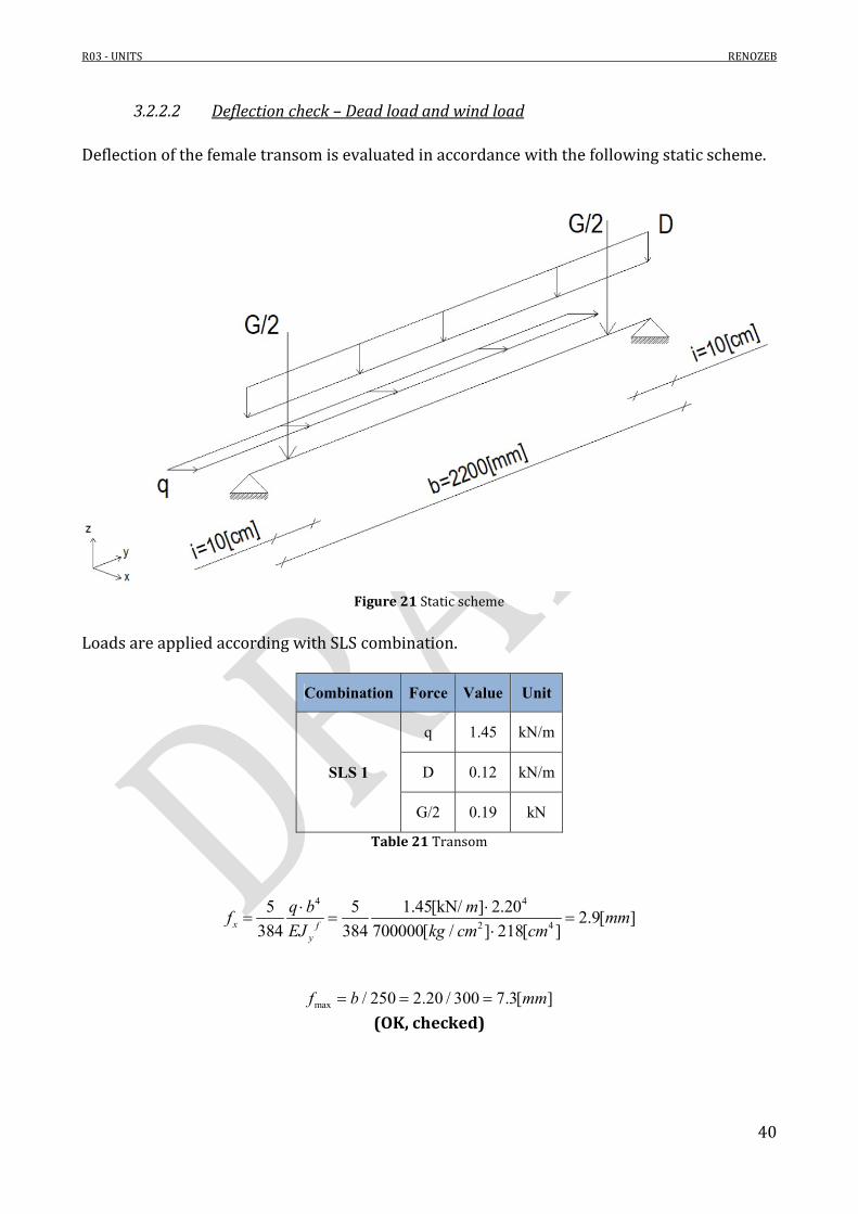
3.2.2.2 Deflection check – Dead load and wind load Deflection of the female transom is evaluated in accordance with the following static scheme.
Figure 21 Static scheme
Loads are applied according with SLS combination.
Combination Force Value Unit
SLS 1
q 1.45 kN/m
D 0.12 kN/m
G/2 0.19 kN
Table 21 Transom
4 4
2 4
5 5 1.45[kN/ ] 2.202.9[ ]
384 384 700000[ / ] 218[ ]x fy
q b mf mm
EJ kg cm cm
max / 250 2.20 / 300 7.3[ ]f b mm (OK, checked)

R03 - UNITS RENOZEB
41
42 2
42 2
2 4 2 4
5 G/ 2(3 4 )
384 24
5 0.12[kN/ ] 2.20 0.19[ ] 10[ ](3 2.2 4 0.1 ) 4.0[ ]
384 700000[ / ] 19.16[ ] 24 700000[ / ] 19.16[ ]
z f fx x
D b if b i
EJ E J
m kN cmmm
kg cm cm kg cm cm
max / 250 2.20 / 300 7.3[ ]f b mm (OK, checked)
It is underlined that, if gres panel is directly connected to the lateral mullion, its weight does not directly loads female transom. For this reason, the deflection of the transom would be lower than the one evaluated.

R03 - UNITS RENOZEB
42
3.2.3 Central transom Central transom is analyzed as follows.
Figure 22 Central transom - section
The following simple static scheme is used in order to analyze the transom
Figure 23 Static scheme

R03 - UNITS RENOZEB
43
According with the previous figure, the uniform loads ‘q’ and ‘D’ are equal to:
2 21 2( ) 1.55[ / ] 2.04[ ] 1.45[ / ]2.20
windW W W kN m mq kN mb
22.2 1.984 4.36[ ]AreaA b h m [unit area]
20.85[ / ]Dead kN m [weight of the unit]
2 20.85[ / ] 4.36[ ] 1.70[ / ]2.2[ ] 2.2[ ]areaDead A kN m mD kN mm m

R03 - UNITS RENOZEB
44
3.2.3.1 Stress check
3.2.3.1.1 Flexural check – Dead load and wind load The maximum stresses are evaluated as follows according with the ULS combinations shown in report R01.
Combination Force Value Unit
ULS 1 q 2.15 kN/m
D 2.2 kN/m
Table 22 Transom
2 22.15[ / ] 2.201.30[kNm]
8 8y
q b kN mM
2 22.2[ / ] 2.201.35[kNm]
8 8x
D b kN mM
Combination ULS 1 – Central transom
max 3 3
1.30[ ] 1.35[ ]108[ ]
27.3[ ] 22.4[ ]y x
f c cy x
M M kNm kNmMPa
w w cm cm
[Female mullion stress]
160df MPa
[Design tensile strength]
/ 0.68 1m df [ok, checked]

R03 - UNITS RENOZEB
45
3.2.3.2 Deflection check – Dead load and wind load Deflection of the central transom is evaluated in accordance with the following static scheme
Figure 24 Static scheme
Loads are applied according with SLS combination.
Combination Force Value Unit
SLS 1 q 1.45 kN/m
D 1.7 kN/m
Table 23 Transom
4 4
2 4
5 5 1.45[kN/ ] 2.202.1[ ]
384 384 700000[ / ] 303[ ]xy
q b mf mm
EJ kg cm cm
[Horizontal deflection]
max / 250 2.20 / 300 7.3[ ]f b mm
(OK, checked)

R03 - UNITS RENOZEB
46
4 4
2 4
5 5 1.70[kN/ ] 2.206.6[ ]
384 384 700000[ / ] 98.22[ ]zx
D b mf mm
EJ kg cm cm
[Vertical deflection]
max / 250 2.20 / 300 7.3[ ]f b mm (OK, checked)
R03 - UNITS RENOZEB
47
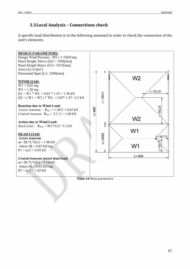
3.3 Local Analysis – Connections check A specific load distribution is in the following assumed in order to check the connection of the unit’s elements. DESIGN PARAMETERS: Design Wind Pressure : WL= 1.55kN/mq Panel Height Above [h2] = 1984[mm] Panel Height Below [h1]= 1015[mm] Area [A]=6.6[m2] Horizontal Span [L]= 2200[mm] WINDLOAD: W1 = 0,85 mq W2 = 1.20 mq Q1 = W1 * WL = 0,85 * 1.55 = 1.30 kN Q2 = ( W1 + W2 ) * WL = 2.05* 1.55 =3.2 kN Reaction due to Wind Load: Lower transom : RW1 = 1.30/2 = 0,65 kN Central transom : RW2 = 3.2 /2 = 1.60 kN Action due to Wind Load: Stack joint : RWL = WL*A/2= 5.2 kN DEAD LOAD: Lower transom m= DL*L*(h1) = 1.90 kN where DL= 0,85 kN/mq P1 = m/2 = 0.95 kN Central transom (panel dead load) m= DL*L*(h2) = 3.70 kN where DL= 0.85 kN/mq P2 = m/2 = 1.85 kN
Table 24 Main parameters
R03 - UNITS RENOZEB
48
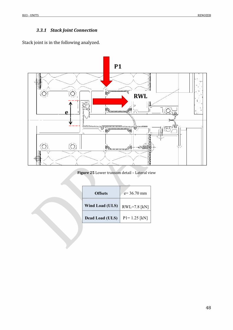
3.3.1 Stack Joint Connection Stack joint is in the following analyzed.
Figure 25 Lower transom detail – Lateral view
Offsets e= 36.70 mm
Wind Load (ULS) RWL=7.8 [kN]
Dead Load (ULS) P1= 1.25 [kN]
P1
RWL
e

R03 - UNITS RENOZEB
49
3.3.1.1 Stack Joint check Tongue Length b= 2200mm
Tongue Thickness t = 3.50 mm
Tongue Stress
2 3
7.8[ ] 36.7[ ]64[ ]
4.5[ ]6
wlb
R e kN mmf MPa
b t cm
160df MPa
[Design tensile strength]
/ 0.40 1b df f [ok, checked]

R03 - UNITS RENOZEB
50
3.3.2 Female transom
3.3.2.1 Screws check Three screws on each end guarantee the connection between the lower transom to the vertical mullions. Forces acting on the connection are Rw1 and P1.
Figure 26 Screws highlight
Shear force on a single screw is evaluated as follows.
11.5( / 3) 1.5(0.95[ ] / 3) 0.50[ ]vF P kN kN
11.5( / 3) 1.5(0.65 / 3) 0.32[ ]h wF R kN
2 2 0.60[ ]h vF F F kN [Screw shear]
Screws are Φ6.3; shear strength is shown in Table 4.
8.9[ ]vR kN
/ 0.07 1vF R [ok, checked]

R03 - UNITS RENOZEB
51
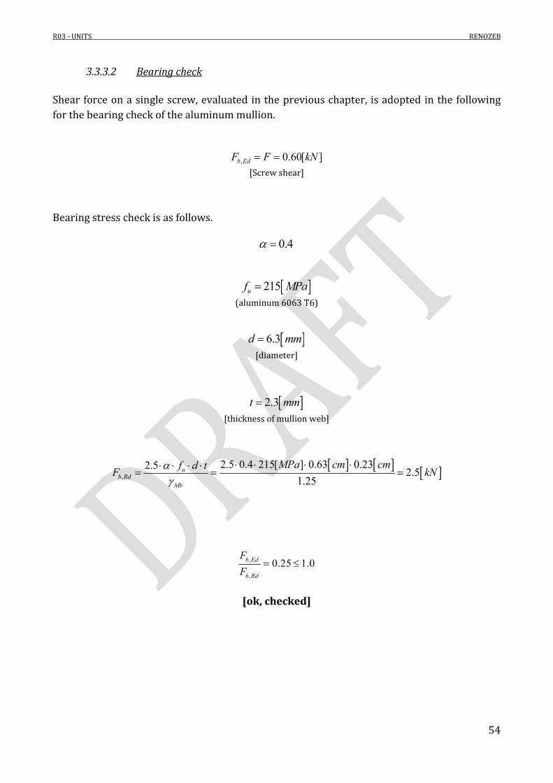
3.3.2.2 Bearing check Shear force on a single screw, evaluated in the previous chapter, is adopted in the following for the bearing check of the aluminum mullion.
, 0.60[ ]b EdF F kN [Screw shear]
Bearing stress check is as follows.
0.4
215uf MPa (aluminum 6063 T6)
6.3d mm
[diameter]
2.3t mm
[thickness of mullion web]
,
2.5 0.4 215[ ] 0.63 0.232.52.5
1.25u
b RdMb
MPa cm cmf d tF kN
,
,
0.25 1.0b Ed
b Rd
F
F
[ok, checked]

R03 - UNITS RENOZEB
52
3.3.3 Central transom Connection The horizontal central transom is connected to the mullion with six screws on each end.
Figure 27 Central transom detail – Lateral view
Wind Load (ULS) RW2=2.4 [kN]
Dead Load (ULS) P2= 2.4 [kN]
P2
RW2

R03 - UNITS RENOZEB
53
3.3.3.1 Screws check As already stated, six screws on each end guarantee the connection between the lower transom to the vertical mullions.
Figure 28 Screws highlight
Shear force on a single screw is evaluated as follows.
2 / 6 2.4[ ] / 6 0.40[ ]vF P kN kN
2 / 6 2.4[ ] / 6 0.40[ ]hF Rw kN kN
2 2 0.60[ ]h vF F F kN [Screw shear]
Screws are Φ6.3; shear strength is shown in Table 4.
8.9[ ]vR kN
/ 0.07 1vF R [ok, checked]
R03 - UNITS RENOZEB
54
3.3.3.2 Bearing check Shear force on a single screw, evaluated in the previous chapter, is adopted in the following for the bearing check of the aluminum mullion.
, 0.60[ ]b EdF F kN [Screw shear]
Bearing stress check is as follows.
0.4
215uf MPa (aluminum 6063 T6)
6.3d mm
[diameter]
2.3t mm
[thickness of mullion web]
,
2.5 0.4 215[ ] 0.63 0.232.52.5
1.25u
b RdMb
MPa cm cmf d tF kN
,
,
0.25 1.0b Ed
b Rd
F
F
[ok, checked]

R03 - UNITS RENOZEB
55
3.4 Durango – Connection to the existing structure
3.4.1 Hook-on Bracket In the following the hook-on bracket is checked. The element is realized by an assembly of aluminum profiles. It allows the connection of the unit to the rear steel bracket, connected to the main structure. Forces acting on a single bracket are mainly an horizontal one and a vertical one. According with Figure 9 it is possible to evaluate the horizontal force. Forces due to the wind load are multiplied by 2.0 factor because it is necessary to take into account the loads that comes from the upper unit.
Combination Force Value Unit
ULS 1 F 0.58 kN
q 2.55 kN/m
ULS 2 F 0.82 kN q 1.53 kN/m
Table 25 Actions
Combination n°1
2.55[ / ] 3
2 2 0.58[ ] 8.25[ ]2 2h
q l kg mF F kN kN
Combination n°2
1.53[ / ] 3.02 2 0.82[ ] 5.5[kN]
2 2h
q l kN mF F kN
Force of combination n°1 is the one assumed in the following. Vertical force is due to the dead load of the unit.
2 2 21.3 0.85[ / ] 1.3 0.85[ / ] 3.3[ ] 3.6[kN]2vAreaF kN m kN m m
Both loads evaluated are applied on each hook.

R03 - UNITS RENOZEB
56
Figure 29 Connection – Lateral view
The hook-on bracket could be considered as an hinge, that rotates next to the connection to the steel plates anchored to the rear wall.
Fv
Fh

R03 - UNITS RENOZEB
57
3.4.1.1 Bolted connection Three M10 allow the connection between the mullion and the hook-on bracket.
Figure 30 Bolts highlight
Forces acting on a single bolt are as follows.
' / 2 8.25[ ] / 2 4.12[kN]h hF F kN [Tensile load on a single bolt]
' / 3 3.6[kN] / 2 1.8[kN]v vF F
[Shear load on a single bolt]
, 22[ ]v RdF kN , 33[ ]t RdF kN
[see Table 3]
,' / 0.09 1v v RdF R
[ok, checked]
,' / 0.12 1h t RdF R
[ok, checked]
, ,
' '0.18 1
1.4v t
v Rd t Rd
F F
RR
[ok, checked]

R03 - UNITS RENOZEB
58
Bearing check Shear force on a single bolt, evaluated in the previous chapter, is adopted in the following for the bearing check of the aluminum mullion.
, ' 1.80[ ]b Ed vF F kN [Screw shear]
Bearing stress check is as follows.
0.4
215uf MPa (aluminum 6063 T6)
10d mm
[diameter]
3.5t mm
[thickness of mullion web]
,
2.5 0.4 215[ ] 1.0 0.352.56.0
1.25u
b RdMb
MPa cm cmf d tF kN
,
,
0.30 1.0b Ed
b Rd
F
F
[ok, checked]

R03 - UNITS RENOZEB
59
3.4.1.2 Bracket check In order to better analyze the behavior of the aluminum bracket when loads are applied, a FE model is realized.
Figure 31 FE model
Forces are applied on the two bolts. On the other hand, restraints are applied where the bracket is connected to the other aluminum bracket.
Fv
Fh
Vertical restraint
Horizontal restraint
R03 - UNITS RENOZEB
60
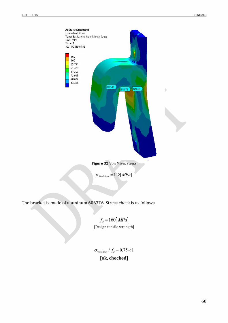
Figure 32 Von Mises stress
118[ ]VonMises MPa
The bracket is made of aluminum 6063T6. Stress check is as follows.
160df MPa
[Design tensile strength]
/ 0.75 1vonMises df [ok, checked]

R03 - UNITS RENOZEB
61
3.4.2 Double ‘C’ aluminum bracket The hook-on bracket analyzed in the previous paragraph is connected to a rear bracket realized by two profiles. A FE model of the system is then realized.
Figure 33 Top view
In order not to overestimate the actions acting on a single bracket, a specific load evaluation is adopted.

R03 - UNITS RENOZEB
62
3.4.2.1 Load evaluation Next to the biggest unit (the one analyzed in this report) there are smaller units. For this reason, loads applied on the connection to the existing structure are as follows.
Figure 34 Top view
(1013 2200) / 2 1600[ ]b mm
21.55[kN/ ]windW m (design maximum pressure, see report R01 – Loads) It must be noted that, in accordance with TU14, wind load and crowd load does not need to be combined together. Both loads must be considered separately and the ones that gives the more severe loading actions is the one to be considered. In this case, wind load is the most stressful action. Combination n°1
2.48[ / ] 31.5 2 1.5 2 11.1[ ]
2 2h
W b l kg mF kN
Vertical force is due to the dead load of the both halves of unit.
2 21.3 0.85[ / ] 1.3 0.85[ / ] 1.60 3.0 5.3[kN]vF kN m b h kN m

R03 - UNITS RENOZEB
63
3.4.2.2 FE model
Figure 35 FE model
Connection to rear steel structure
Connection to rear steel structure
M10 bolts
M10 bolts

R03 - UNITS RENOZEB
64
Figure 36 Von Mises stress
151[ ]VonMises MPa
The bracket is made of aluminum 6063T6. Stress check is as follows.
160df MPa
[Design tensile strength]
/ 0.94 1vonMises df [ok, checked]
It is underlined that the peaks shown in the stress results are due to the mesh dimensions. Moreover, model does not take into account the nuts that allow to distribute the force on the aluminum plate.

R03 - UNITS RENOZEB
65
3.4.3 Connection to the concrete slab On the back of the two brackets analyzed in the previous paragraphs, a steel bracket is installed. Loads applied on the external edge of the bracket, where the double ‘C’ aluminum bracket is connected with bolts.
Figure 37 Frontal view
Figure 38 Top view

R03 - UNITS RENOZEB
66
3.4.3.1 FE model From the model adopted in chapter 3.4.2.2 it is possible to evaluate the actions transferred to the steel bracket. These actions are then applied to the model. Results are shown in the following.
Figure 39 Von Mises Stress
308[ ]VonMises MPa
The bracket is made of aluminum Steel S355. Stress check is as follows.
338ydf MPa
[Design tensile strength]
/ 0.91 1vonMises df [ok, checked]
R03 - UNITS RENOZEB
67
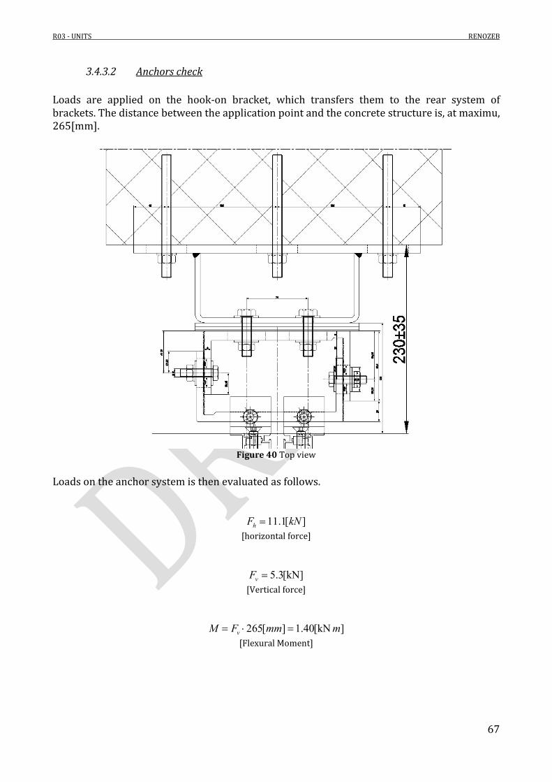
3.4.3.2 Anchors check Loads are applied on the hook-on bracket, which transfers them to the rear system of brackets. The distance between the application point and the concrete structure is, at maximu, 265[mm].
Figure 40 Top view
Loads on the anchor system is then evaluated as follows.
11.1[ ]hF kN [horizontal force]
5.3[kN]vF [Vertical force]
265[ ] 1.40[kN ]vM F mm m [Flexural Moment]

R03 - UNITS RENOZEB
68
The following hypothesis are assumed:
Concrete C12/15;
Cracked Concrete;
Embedment length equal to 70[mm];
15[mm] of mortar between steel plate and concrete structure.
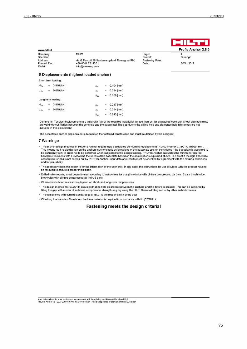
Check on the anchors is performed in accordance with the Hilti free software. Refer to Annex A for the structural report. Actions on a single steel bar must be compared to the values obtained on site during a test. In particular:
Maximum tensile force equal to 5.3[kN];
Maximum shear force equal to 3.6 [kN].
In the Hilti report (Annex A) actions on every anchor are determined.
Figure 41 Forces on anchors
As shown in the previous figure, both tensile forces and shear ones are lower than the ones tested on site in accordance with an ULS combination.

R03 - UNITS RENOZEB
69
4. Annex A

R03 - UNITS RENOZEB
70

R03 - UNITS RENOZEB
71
R03 - UNITS RENOZEB
72

R03 - UNITS RENOZEB
73
R03 - UNITS RENOZEB
74
Related Documents