MA300 EMG System User Guide By Motion Lab Systems, Inc.

Welcome message from author
This document is posted to help you gain knowledge. Please leave a comment to let me know what you think about it! Share it to your friends and learn new things together.
Transcript

MA300 EMG System
User Guide
By Motion Lab Systems, Inc.

This manual was written by Motion Lab Systems using ComponentOne Doc-To-Help.™
Updated Sunday, November 11, 2012
Trademarks
All trademarks and registered trademarks are the property of their respective owners.
Motion Lab Systems, Inc. 15045 Old Hammond Highway • Baton Rouge, LA 70816-1244
Phone (225) 272-7364 • Fax (225) 272-7336
Email: [email protected]
http://www.motion-labs.com
Printed in the United States of America
© Motion Lab Systems, Inc. 1997-2012

MA300 EMG System User Guide Contents i
Contents
Important Information 3
Warranty .................................................................................................................................... 3 Mandatory Warnings ................................................................................................................. 4 FCC Regulatory Information – MA300-DTU ........................................................................... 6 FCC Regulatory Information – MA300-RTT ............................................................................ 7 CB Test Certificate .................................................................................................................... 8 Declaration of Conformity ......................................................................................................... 9 International Standards ............................................................................................................ 10
Introduction 11
Features .................................................................................................................................... 11 Specifications ........................................................................................................................... 13 System Specifications .............................................................................................................. 15 Maintenance ............................................................................................................................. 20
Setting up the MA300 system 23
Getting started .......................................................................................................................... 23 Working with C3D files ........................................................................................................... 27
System Displays 35
Signal Displays ........................................................................................................................ 35 Fault Detection and Troubleshooting ....................................................................................... 36
Using the MA300 39
Connections ............................................................................................................................. 39
Making an EMG recording 47
Getting started .......................................................................................................................... 47 Subject Testing ........................................................................................................................ 52
Radio Telemetry 53
Using Radio Telemetry ............................................................................................................ 53 Radio Telemetry Quality ......................................................................................................... 56 Diversity Receiver Option ....................................................................................................... 59
Operational Tests 61
System Operation ..................................................................................................................... 61 EMG signal reference .............................................................................................................. 62 Hardware Calibration ............................................................................................................... 63

ii Contents MA300 EMG System User Guide
Test Procedures 65
Overview .................................................................................................................................. 65 Desk Top Unit Tests ................................................................................................................ 65 Back Pack Unit Tests ............................................................................................................... 69 EMG Preamplifier Testing ....................................................................................................... 76
Connections 81
Signal Connections .................................................................................................................. 81 EMG signal filters .................................................................................................................... 86
Appendix A 89
Analog event switch levels ...................................................................................................... 89
Appendix B 91
Upgrading the MA300 ............................................................................................................. 91
Appendix C 97
Installation ............................................................................................................................... 97
Index 103

MA300 EMG System User Guide Important Information 3
Important Information
Warranty Motion Lab systems, Inc., warrants that each MA300 system, comprising of the
Desk Top Unit and Back-Pack Unit will be free from defective materials and
construction for twenty-four (24) months from the date of installation.
In no case shall Motion
Lab Systems, Inc be liable
for any consequential or
incidental damages for
breach of this or any other
warranty, express or
implied.
Motion Lab Systems, Inc., agrees to correct any of the above defects (parts and labor
only) when the complete system is returned to the factory freight prepaid by the
customer. Return authorization must be obtained from Motion Lab Systems before
returning the system to the factory. The repaired system will be returned to the
customer freight prepaid during the warranty period. Hardware Service Contracts are
available to extend this warranty. Under this warranty Motion Lab Systems may, at
its option, repair or replace the defective system or system components.
This warranty will be invalid if, in the sole judgment of Motion Lab Systems, the
system has been subjected to misuse, abuse, neglect, accident, improper installation
or application, alteration or neglect in use, storage, transportation or handling.
Consumable items (such as
preamplifiers, cables etc)
are warranted for 30 days
from initial use.
The preamplifiers, cables, event switches and other items that may be supplied with
the backpack and desktop unit are considered to be consumable items and are
warranted to 30 days from initial use. These items are considered to have a limited
life and should be replaced when necessary. Additional foot switches, pre-amplifiers
and cables may be ordered directly from Motion Lab Systems or your distributor.
Intended Use
The Motion Lab Systems, Inc., MA300 EMG system is designed for Clinical,
Investigational, Scholarship and Research use and may be used in the treatment and
diagnosis of human beings.
All MA300 systems have received US FDA 510(k) clearance (Sec. 890.1375) for use
as a diagnostic electromyograph with human beings. A diagnostic electromyograph
is defined by the US FDA as:
A diagnostic electromyograph is a device intended for medical purposes, such as to
monitor and display the bioelectric signals produced by muscles, to stimulate
peripheral nerves, and to monitor and display the electrical activity produced by
nerves, for the diagnosis and prognosis of neuromuscular disease. [21CFR890.1375]

4 Important Information MA300 EMG System User Guide
Mandatory Warnings
Read Manual before Use
The MA300 is an AC line powered device - make sure that you read this manual
(User Manual) before operating the MA300 EMG system or connecting the MA300
system to any other device.
Warning – High Voltage Inside
CLASS I EQUIPMENT energized from an external power source as defined by UL
60601-1.
TYPE BF protection from electrical shock as defined by UL 60601-1.
Unauthorized personnel must not disassemble the MA300 Desk Top Unit without
taking the appropriate precautions to ensure safety.
Warning - Connect to a Grounded Outlet Only!
Safe and effective operation of this device requires a three wire AC power
connection with an electrical ground (earth) connection.
SIP/SOP Connections
Accessory equipment connected to the analog and digital interfaces must be certified
according to the respective IEC standards (i.e. IEC 950 for data processing
equipment and IEC 601-1 for medical equipment). Furthermore all configurations
shall comply with the system standard IEC 601-1-1.
Everybody who connects additional equipment to the signal input part or signal
output part configures a medical system, and is therefore responsible that the system
complies with the requirements of IEC 601-1-1. If in doubt, consult the technical
services department or your local representative.
Fuse Replacement
The MA300 Desk Top Unit uses 500mA/250V SLO-BLO fuses only.
In the event of a fuse requiring replacement you must replace the AC line fuses with
500mA/250V SLO-BLO fuses to maintain protection.
Maintenance
The MA300 system is designed to be maintenance free and does not require any
regular maintenance to ensure safe and effective operation.
Cleaning
The surfaces of the MA300 system and preamplifiers may be cleaned and sterilized
with a damp cloth and mild detergent or with isopropyl alcohol swabs. The MA300
System is NOT SEALED. DO NOT IMMERSE IN WATER OR ANY OTHER
SOLUTION. The MA300 system is not designed for use in a sterile environment.
DO NOT subject the MA300 system to any sterilization procedure.

MA300 EMG System User Guide Important Information 5
Anesthetic Environment
The MA300 is not suitable for use in the presence of a FLAMMABLE
ANAESTHETIC MIXTURE WITH AIR OR WITH OXYGEN OR WITH
NITROUS OXIDE or in the presence of other explosive gases or vapors.
Contraindications
DO NOT USE on irritated skin or open wounds.
Discontinue use immediately if skin irritation or discomfort occurs.
Use with HF Surgical Equipment
Connection of a patient to HF surgical equipment and to an electromyograph or
evoked response equipment simultaneously may result in burns at the site of the
electrical stimulator or biopotential input part electrodes and possible damage to the
electrical stimulator or biological amplifiers.
Additional Documentation
Motion Lab Systems will make the following items available on request; circuit
diagrams, component parts lists, descriptions and calibration instructions. Please
contact Motion Lab Systems, Inc. or your local distributor for further information.

6 Important Information MA300 EMG System User Guide
FCC Regulatory Information – MA300-DTU
Product Information
Product Name Motion Lab Systems EMG System
Model Number MA300
FCC Rules Tested To Comply With FCC Part 15, Class B
Operating Environment For Home Or Office Use
FCC Compliance Statement
This equipment complies with Part 15 of the FCC Rules. Operation is subject to the
following conditions: (1) this device may not cause harmful interference, and (2) this
device must accept any interference received, including interference that may cause
undesired operation.
Information to the User
This equipment has been tested and found to comply with the limits for a Class B
digital device, pursuant to Part 15 of the FCC rules. These limits are designed to
provide reasonable protection against harmful interference in a residential or office
installation. This equipment generates, uses, and can radiate radio frequency energy
and if not installed and operated in strict accordance with the manufacturer’s
instruction, may cause interference to radio communications. However, there is no
guarantee that interference will not occur in a particular situation. Interference can be
determined by turning the equipment off and on while monitoring radio or television
reception. The user may be able to eliminate any interference by implementing one
or more of the following measures:
Reorient the affected device and/or its receiving antenna.
Increase the distance between the affected device and the equipment.
Plug the equipment and any peripheral equipment into a different branch
circuit from that used by the affected device.
If necessary, consult an experienced technician for additional suggestions.
Caution: Changes or modifications to the electronics or enclosure to this unit that are
not expressly approved by the party responsible for compliance could void the user’s
authority to operate the equipment.

MA300 EMG System User Guide Important Information 7
FCC Regulatory Information – MA300-RTT
RF Transmitter Installation Instructions
The MA300-RTT transmitter should only be installed by qualified service personnel.
The transmitter connects to the MA300 BPU unit with the supplied LEMO cable. It
supplies power to the BPU from its internal rechargeable battery.
INSTALLATION INSTRUCTIONS
1. Connect the MA300RTT transmitter to the BPU. Ensure that the battery of the
MA300RTT is fully charged and press the power switch. The LED lights should
indicate the presence of the digital signal from the BPU and the battery charge state.
2. Select a channel that does not conflict with other MA300-RTT units by setting the
rotary switch. The MA300-RTR receiver should be connected to the DTU and must
have its channel select switch set to the same channel as the MA300-RTT
transmitter. The MA300-RTR receiver is powered by the DTU and does not need an
external power supply.
3. If possible, avoid installing MA300-RTT in areas near large metallic objects such
as air conditioners, heaters, screens and heaters.
FCC NOTICE
The Model MA300-RTT transmitter generates and uses radio frequency energy. If
not installed and used in accordance with the manufacturer's instructions, it may
cause interference to radio and television reception. The transmitter has been tested
and found to comply with the specifications in Part 15 of FCC Rules for Intentional
Radiators and FCC Part 15 Subpart C, Specifications.
If this equipment causes interference to radio or television reception - which can be
determined by turning the equipment on and off - the installer is encouraged to
correct the interference by one or more of the following measures: 1) Reorient the
antenna of the radio/television. 2) Connect the MA300 DTU to a different outlet so
the control panel and radio/television are on different branch circuits. 3) Relocate the
control panel with respect to the radio/television.
If necessary, the installer should consult an experienced radio/television technician
for additional suggestions, or send for the "Interference Handbook" prepared by the
Federal Communications Commission. This booklet is available from the U.S.
Government Printing Office, Washington, D.C., 20402. Stock number 004-000-
00450-7.
CAUTION: No field changes or modifications to the MA300-RTT should be made
unless they are specifically covered in this manual.
All adjustments must be made at the factory under the specific guidelines set forth in
our manufacturing processes. Any modification to the equipment could void the
user's authority to operate the equipment and render the equipment in violation of
FCC Part 15, Subpart C, 15.247.
This device complies with Part 15 of the FCC Rules. Operation is subject to the
following two conditions: (1) this device may not cause harmful interference, and (2)
this device must accept any interference received, including interference that may
cause undesired operation.

8 Important Information MA300 EMG System User Guide
CB Test Certificate

MA300 EMG System User Guide Important Information 9
Declaration of Conformity

10 Important Information MA300 EMG System User Guide
International Standards
Canada
CSA C22.2 NO 601.1-M90 Medical Electrical Equipment - Part 1: General
Requirements for Safety General Instruction No 1: Supplement 1; 1994 R (1997).
This digital apparatus does not exceed the Class B limits for radio noise emissions
from digital apparatus set out in the Radio Interference Regulations of the Canadian
Department of Communications.
Le present appareil numerique n'emet pas de bruits radioelectriques depassant les
limites applicables aux appareils numeriques de la class B prescrites dans le
Reglement sur le brouillage radioelectrique edicte par le ministere des
Communications du Canada.
European Community
CENELEC EN 60601-1 - Medical Electrical Equipment Part 1:
IEC 60601-2-40 - Particular Requirements for Electromyographs and Evoked
Response Equipment.
General Requirements for Safety Incorporates Corrigendum July 1994; Includes
Amendments A1: 1993, A11: 1993, A12: 1993, A2: 1995 and A13:1996; IEC 601-1:
1988 + A1: 1991 + A2: 1995 +
CENELEC EN 60601-1-2 - Medical Electrical Equipment Part 1: General
Requirements for Safety 2. Collateral Standard: Electromagnetic Compatibility -
Requirements and Tests (IEC 601-1-2: 1993) - EMISSIONS
CENELEC EN 60601-1-2 - Medical Electrical Equipment Part 1: General
Requirements for Safety 2. Collateral Standard: Electromagnetic Compatibility -
Requirements and Tests (IEC 601-1-2: 1993) – IMMUNITY
EU Contact: Motion Lab Systems, Ltd. Green Acres, Templebar Rd. Pentlepoir,
Kilketty, Pembrokeshire, SA680RA
Type of Equipment: EMG System.
Manufacturer: Electronic Manufacturing Co., 13440 Wright Circle, Tampa, FL
33626 USA. Telephone: +1 (813) 855-4068
Responsible Party: Motion Lab Systems, Inc., 15045 Old Hammond Hwy, Baton
Rouge, LA 70816 USA. Telephone: +1 (225) 272-7364
http://www.motion-labs.com
United States of America
UL 2601-1 - UL Standard for Safety Medical Electrical equipment, Part 1: General
Requirements for Safety Second Edition.
The MA300 system and pre-amplifiers have received US FDA 510(k) clearance
(Sec. 890.1375) for use as a diagnostic electromyograph for medical purposes with
human beings. The preamplifier device listing is D143183, FDA510(k) K974385
and the MA300 system listing is E443972, FDA510(k) K000220.
Our FDA Establishment Registration number is 2320542.

MA300 EMG System User Guide Introduction 11
Introduction
Features
All MA300 systems have
received US FDA 510(k)
clearance (Sec. 890.1375)
for use as a diagnostic
electromyograph for
medical purposes on
human beings.
Welcome to the User Guide for the Motion Lab Systems MA300 Electromyography
systems. These are a range of high quality EMG systems intended for use in the
investigation of the physiological process involved in muscle contraction and can be
used to record multiple channels of EMG data from human beings in a clinical
environment - either as a stand-alone system, or with a motion capture or gait
analysis system. These systems enable the user to observe the electromyographic
signals that are produced when muscles contract, while maintaining the electrical
isolation of the subject from any measuring or recording equipment that is attached
to the system.
All MA300 EMG systems
consist of two units (a
backpack and desktop unit)
with a single thin (2.66 mm
diameter) coaxial connecting
cable. The subject carries the
backpack, attached to a belt
or vest, with EMG pre-
amplifiers and up to eight
event switches. The EMG,
event switch and other
signals are digitized and
processed within the
backpack and transmitted as
digital information to the
desktop unit over the coaxial
cable. This is a single core,
ultra-light cable, 18 to 35 metres long that weighs less than 160 grams and does not
encumber the subject in any way. The standard MA300 system does not use radio or
infrared telemetry and can be used in almost any environment without any of the
restrictions of wireless telemetry systems.
The MA300 system meets
FCC Class B requirements
and can normally be
operated near magnetic,
electrostatic, and radio-
frequency fields without
problems.
The MA300 is a small, lightweight and versatile system that avoids the problems of
radio frequency interference inherent in traditional EMG radio telemetry systems.
The ultra-light cable used does not restrict the subject in any way, unlike the
cumbersome, multi-core cables required to transmit data in the traditional cabled
EMG systems where a separate cable is used for each channel of information. By
digitizing all signals at the subject, the MA300 guarantees a clean signal without any
degradation from the transmission of analog signals.

12 Introduction MA300 EMG System User Guide
The backpack receives isolated low-level DC power from the desktop interface unit
over the same cable that carries the EMG signal. This keeps the backpack unit
lightweight, makes the system simple and reliable to use, and eliminates the need and
expense of batteries. Since the system does not use radio frequencies there is no risk
of interference or interaction with other equipment. Sophisticated electronic circuits
within both units enable the reliable supply of power to the subject backpack while
simultaneously transmitting digital information over the same cable. In addition,
electrical isolation of the subject is maintained at all times.
Motion Lab Systems offers
a range of features in the
backpacks making them
suitable for any gait or
biomechanics application.
The backpack is attached to a belt or vest worn by the subject and supports a
number of EMG pre-amplifier channels. Our range of backpacks extends from basic
units with only the essential features to units that include additional features such as
a user controlled anti-alias filter, eight dedicated channels for event switches and
four dedicated, low frequency, auxiliary channels for use with goniometers,
accelerometers, strain gauges etc.
All backpacks feature an adjustable gain switch for each EMG channel that can be
preset to any one of ten different values. This guarantees that your MA300 EMG
System has a precise gain setting at all times while allowing the user complete
control of the output signal levels. Each
EMG channel includes an individual blue
LED next to the gain control switch that
lights when the signal level is close to an
overload condition to warn the user if the
gain control is set too high. In addition, all
backpacks also include a recessed test button
at the bottom of the backpack that allows the
user to test each of the EMG channels by
applying a 78Hz sine wave signal to all of the
EMG channels – this can be used to
automatically calculate the individual
channel gain settings when using the Motion
Lab Systems EMG Graphing or EMG Analysis software applications.
Some backpack models contain additional features such as an extended frequency
response and an adjustable anti-alias filter that can preset the maximum EMG
frequency that will be processed to avoid the possibility of recording signal aliasing
errors. The ability to control the EMG bandwidth allows the user to specify the
precise EMG bandwidth that they will work with and can easy EMG data collection
in many cases. Backpacks without an anti-alias filter switch have a fixed DC-
1000Hz -3dB bandwidth.
Unlike other EMG systems
designed for biofeedback,
animal, or research use, all
MA300 systems meet the
requirements for use in the
United States on human
subjects in a clinical
environment.
A single green power light on the front of the backpack indicates that the unit is
receiving DC power from the desktop unit, while individual blue lights next to each
of the EMG channel gain controls alert the user to any potential signal overload on
the individual EMG channels. The coaxial connector to the desktop interface cable is
on the left side of the bottom of the unit while a green indifferent (or ground
reference) connector is located on the bottom right side. This is a standard
“TouchProof” DIN 42-802 connector that can be used to connect a ground reference
electrode to the system that meets the performance standard for Electrode Lead
Wires and Patient Cables, in Title 21 Code of Federal Regulations (CFR), part 898.
The desktop interface unit contains the isolated electrical interface to the subject
unit. It supplies isolated, low-level, DC power to the backpack unit and converts the
digitized EMG signals to analog signals suitable for connection to any data
collection system. Front panel status lights show the DC power status and provide
fault detection (No Signal) plus an indication of signal quality (the CRC light).
Activity indicators for the eight dedicated event switch channels provide easy

MA300 EMG System User Guide Introduction 13
individual switch monitoring and testing when using a backpack that supports
dedicated event switch channels. These indicators do not indicate the status of event
switches used in the EMG and Auxiliary channels. All MA300 backpacks support
the use of event switches connected to the auxiliary or EMG data channels but only
the dedicated event switch channels are displayed on desktop interface unit front
panel.
Many Motion Capture systems and software
analysis packages can automatically determine
gait events and if you are using one of these
systems with your MA300 then you may not need
the event switches. Many data capture systems
also provide facilities to directly monitor the
EMG and other analog signals.
Your MA300 system will produce high quality
raw EMG signals under clinical conditions
without requiring any complicated set up or
training period - if you can find the muscle, then
the MA300 will provide the signal. The system
has been designed to be reliable and easy to use
under all circumstances and is supplied with
EMG pre-amplifiers and all the cables needed to
connect to any motion capture system or ADC
system to start recording EMG and event data.
The easy upgrade path for all of the MA300
systems ensures that an EMG system can by
purchased by any user with the confidence that
additional capabilities can be added as the needs
change.
Analog signal connection and installation
information can be found at the end of this
manual. Please contact technical support at
Motion Lab Systems if you have any questions concerning the installation or signals
provided by your MA300 system.
Specifications The MA300 system is available in a range of different configurations to match the
needs of a wide range of users. MA300 systems meet all basic gait lab requirements
as well as those of advanced research users:
MA300-XII has 12 data channels – this system has a fixed 1000Hz
bandwidth and includes eight EMG channels and four auxiliary channels
that can be used with event switches.
MA300-XVI has 16 data channels – this system has a fixed 1000Hz
bandwidth that features sixteen EMG channels but does not include any
auxiliary or event channels.
MA300-18 has 18 data channels – this system has an adjustable low pass
filter, six EMG channels, eight event switches and four auxiliary
channels.

14 Introduction MA300 EMG System User Guide
MA300-22 has 22 data channels – this system has an adjustable low pass
filter, ten EMG channels, eight event switches and four auxiliary
channels.
MA300-28 has 28 data channels – this system has an adjustable low pass
filter, sixteen EMG channels, eight event switches and four auxiliary
channels.
All MA300 systems consist of a Subject Back-Pack Unit (BPU), a Desk-Top Unit
(DTU) and interconnecting coaxial cable with various accessories such as the EMG
pre-amplifiers and event switches. This specification covers the two main electronic
packages: the Back-Pack Unit (BPU) and the Desk-Top Unit (DTU). Electrical
parameters are defined between the input connectors of the BPU and the 25 pin
signal connector on the rear of the DTU.
MA300 systems are available with two different input connector types for the EMG
and auxiliary channels – these can be either 4-pin BINDER or LEMO connectors.
All MA300 systems supporting dedicated event channels use the same connector
type for the event channels, a 5-pin LEMO connector. If you are using event
switches connected to the auxiliary channels or via any of the EMG channels then
the event switch connector will normally be
a 4-pin BINDER connector.
All of the EMG channels in MA300
systems have identical signal processing
facilities with the exact frequency range
depending on the model. MA300 systems
without a variable anti-alias filter have a
fixed DC-1000Hz bandwidth while our high-
end systems can set the upper bandwidth via a
user controlled filter.
Systems featuring dedicated events channels have
two event switch input connectors, each with four
binary switch inputs. The dedicated event switch specifications apply to each of the
eight total binary input channels that are available as a pair of encoded analog
channels at the MA300 output connector. In addition, many MA300 systems also
include four auxiliary channel inputs that accept low data rate signals with a
bandwidth of DC to 120Hz.
All MA300 systems can accommodate an optional internal band-pass filter assembly
in the DTU that provides a variable high-pass filtering as well as a pre-set low-pass
filter for each EMG channel. These can be set to ensure that the EMG signals
produced by the MA300 do not exceed the capabilities of the user’s external analog
system data collection system. This optional filter is fitted in the DTU in addition to
the built-in low-pass filter in the MA300 backpack. Full details of the optional band-
pass filter can be found at the end of this manual - the quoted specifications for the
MA300 system assume that the optional band-pass filter has not been fitted.
All MA300 systems share a common feature set, design and construction methods
that ensure that all our systems share a common performance baseline within the
design limits of the specified features of each system.
Motion Lab Systems reserves the right to alter or amend specifications without
notice.

MA300 EMG System User Guide Introduction 15
Performance Conditions
The following electrical specifications are valid for the MA300 electronic units after
a 15-minute warm-up, an ambient temperature of 20C to 30C and 40 to 60%
relative humidity (non-condensing).
All MA300 systems are tested to meet performance and electrical safety
specifications before shipment.
These specifications apply to all MA300 systems unless otherwise noted.
MA300 Characteristics
The characteristics of the MA300 are grouped into EMG, Auxiliary (Low Speed)
channels, Event Switch, Power Line, Environmental, and Physical. Unless otherwise
noted, it is assumed that the system is a cabled MA300 system set up for the default
conditions with a DC to 2000 Hz system bandwidth and preamplifiers that include a
10Hz high pass filter. It is further assumed that the EMG mid-band test frequency is
a 200 Hz sine wave.
System Specifications
Number of EMG channels 6, 8, 10 or 16 depending on model selected.
Dedicated event channels 8 binary (on/off) event channels (if fitted).
Number of Auxiliary channels 4 channels, DC to 120Hz (if fitted).
EMG signal output level ±5 Volts Full Scale.
Variable Low Pass Filter 10 pole Bessel, -3dB at 350, 500, 750, 1000, 1250,
1500, 1750 and 2000 Hz.
Fixed Low Pass Filter 10 pole Bessel, -3dB fixed at 1000 Hz.
Group Delay (input to output) < 2ms @ 1kHz (cabled and telemetry systems)
Electrical Isolation 1500 V DC Applied part
EMG pre-amplifier input noise Less than 2 μV RMS nominal, C.M.R.R. >100 dB
at 40 Hz.
AC input rating 100-240 Volts, 50VA, 50/60 Hz
All MA300 signal outputs are electrostatic discharge protected, in addition, all
Motion Lab Systems EMG pre-amplifiers supplied with the MA300 are ESD and
RFI protected.
Event channels and the Variable Low Pass Filter are features of the high-end MA300
systems. Some MA300 systems do not have dedicated event channels and have a
fixed EMG signal bandwidth. Auxiliary channels are not available on the MA300-
XVI system.
Subject Back-Pack Characteristics
EMG Inputs
Input Impedance 31 KΩ At the backpack input connectors.
Input max Level 500 mV Peak to Peak

16 Introduction MA300 EMG System User Guide
Backpack Bandwidth DC – 2,000 Hz* -3 dB at 2kHz.
Internal sample Rate 5,000 samples / sec. Per individual EMG channel.
Unit Gain Range 10 to 500 (± 5%) ten (10) switch settings.
Signal to Noise Ratio >50 dB (At full scale output)
Crosstalk >50 dB Adjacent EMG channels
* MA300-XII and XVI backpacks are limited to 1kHz.
All second generation MA300 backpacks generate an internal test signal that is a
78Hz sine wave of 8.8mV peak to peak applied to the backpack inputs. This is
equivalent to a peak to peak signal level of 440uV at the input of a standard (x20
gain) preamplifier.
Low Speed auxiliary Inputs (where available)
Input Impedance 31 KΩ At the backpack input connectors.
Input max Level 2.5 Volt Peak to Peak
Signal to Noise Ratio >40 dB (At full scale output)
Crosstalk >40 dB Inter channel crosstalk.
DC Power available 5 Volts at 10 mA Isolated DC power.
Desk-Top Unit Characteristics
EMG Outputs
Output Impedance 100 ohms, 10% ±5 Volts max at 10 mA.
Desk Top Unit Gain 2 (± 5%) ±5 Volts full scale output.
Over Voltage Protection ±5.2 Volts Zener clamped.
EMG Subject Isolated Interface
Hi Pot Test 1500 V DC for 10 seconds ( <1 mA)
EMG Pre-amplifier Characteristics
The surface EMG pre-amplifiers supplied with the may use pre-gelled snap Ag/AgCl
electrodes, surface-mounted disks, or fine wires with a suitable adaptor.
All preamplifiers feature a built-in instrumentation amplifier using a dual differential
front-end, full static (ESD) protection, muscle stimulator protection, and include a
Radio Frequency Interference (RFI) filter.
Input Impedance > 100,000 MΩ.
Input Configuration Dual Differential front-end
Input Protection > ± 40V DC
Equivalent Input Noise < 2V RMS nominal.
C.M.R.R. > 100 dB min at 40 Hz.
Bandwidth (-3 dB) 10Hz to 3.5kHz (MA420), 20Hz to 3.5kHz (MA411/416)

MA300 EMG System User Guide Introduction 17
Pre-amplifier Gain 20 (± 2%).
Body size 38 mm x 19 mm x 9 mm.
Weight 20 grams.
Connector 4-pin BINDER or LEMO connector
Dedicated Event Inputs (if fitted)
Input Impedance 10 KΩ 3% Pulled to 5 Volt DC
Logic Threshold 2 to 3 Volts DC
Delay (ON or OFF) < 1.5 msec
Pressure to "close" Less than 150 gm
Analog Outputs 0 to 4.688 Volts Full Scale
Analog Impedance 100 ohms 5 mA maximum
Analog Encoding Weighted binary 1, 2, 4, 8
Analog Accuracy 0.6% of Full Scale10 mV DC absolute.
Connector 5-pin LEMO.
AC Power Supply Characteristics
Connector 3 pin IEC 622 style
Line Volts Auto selected - working range 100 - 240 Volts AC.
Line Frequency 50/60 Hz.
User Replaceable Fuses Dual 500 milliamp, slo-blow 20 mm fuses.
Wattage 40 VA
Safety Compliance The AC power supply (Condor GSM28-12) is certified to
be in compliance with the applicable requirements of UL-
2601-1 First Edition, CSA 22.2 No. 601.1 and IEC601-1
1988 Amend. 2. The unit is in conformity with the
applicable requirements of EN60950 following the
provisions of the Low Voltage Directive 73/23/EEC.
Environmental Characteristics
Operating Temperature 20C to 40C
Storage Temperature -15C to 55C
Relative Humidity Maximum 90%, no condensation.
Shock (two hits) 30 G max each axis
Physical Characteristics
Subject Unit dimensions 135 x 105 x 42 mm. 5.2 x 4.2 x 1.6 inch (DxWxH)
Subject Unit Weight 0.4 Kg (14 Ounces)

18 Introduction MA300 EMG System User Guide
Interface Unit dimensions 318 x 75 x 290 mm. 12.5 x 3.0 x 11.5 inch (DxWxH)
Interface Unit Weight 4.3 Kg (9.5 lb.)
The desk top unit enclosure is made from injection molded glass-reinforced
polycarbonate and is rated V-O in the UL flammability test.
Group Delay
The delay from an EMG signal at an MA300 preamplifier to the analog output of the
MA300 system is called the Group Delay and constant across all EMG channels.
Due to the unique design of the MA300 system the group delay remains constant for
both the traditional cabled MA300 systems and MA300 systems that use the radio
telemetry option. Switching between cabled data transmission and radio telemetry
data transmission does not affect the group delay.
The group delay that an EMG system adds to the EMG signals is an important factor
whenever EMG data is sampled and analyzed in combination with motion or force
data. This is because large delays (greater than the motion or force sampling rates)
in the EMG data will cause a loss of synchronization between the EMG signal and
the motion or force data. All MA300 systems have a group delay less then 2ms
(EMG bandwidth >1kHz) thus typical 3D systems that sample data at 60 or 120
frames (samples) per second will remain perfectly synchronized with EMG data
from any MA300 system.
Figure 1- 1ms pulse applied to the preamplifier input (green) with MA300 output (blue).
The only factor that affects the total group delay from signal input to signal output is
the high frequency bandwidth of the MA300 backpack – MA300-XII and MA300-
XVI systems have a fixed bandwidth with an associated group delay of less then 2ms
across all EMG channels.
MA300-18, -22, and -28 systems with the built-in low-pass filter will have a group
delay that is proportional to the low-pass filter settings – this can range from 1.2ms
at 2kHz bandwidth to 4.4ms at the lowest 350Hz filter setting. In all cases this delay
is less than the sample resolution of a 3D motion capture system running at 120Hz

MA300 EMG System User Guide Introduction 19
frame rate (8.3ms) so EMG data recorded in combination with 3D motion data is
always perfectly synchronized when using MA300 EMG systems.
The group delay of the MA300 system remains unchanged when the MA300-RT
radio-telemetry option is used. However, using the diversity receiver option will add
an additional 250ns to the overall system group delay. This is insignificant when
compared to the typical Group Delays of competing radio-telemetry EMG systems
which can introduce EMG signal delays of 15-50ms as shown in the illustration
below when testing a well known competing commercial telemetry EMG system
under identical conditions to the MA300 Group Delay test.
Almost all commercial
EMG radio telemetry
systems have larger Group
Delays than the minimal
delay of an MA300 EMG
system.
This illustrated 15.6ms delay between the EMG signal detection at the skin surface,
and the signal appearing at the analog output, is equivalent to a delay of 2 frames of
3D data at 120Hz (8ms per frame). This means that, when EMG data is recorded
with one of these systems in a gait environment, the 3D marker position data and
force plate data will be recorded in real-time but the EMG data will lag the real-time
data by 2 frames with this competing system. Many commercial wireless telemetry
systems have even longer delays resulting in substantial synchronization problems.
Figure 2 - A typical Group Delay generated by a competing telemetry EMG system.
The corresponding Group Delay introduced by an MA300-28 system is only 1.1ms
at full 2kHz bandwidth, offering real-time performance and making video and 3D
motion capture data synchronization error free. In addition to a minimal delay, the
full EMG bandwidth of the MA300 systems results in a much cleaner and more
accurate EMG signal than competing, lower bandwidth systems with low quality
filters that distort the EMG signals.
System Connections
All MA300 systems consist of two units, a desk-top interface unit and subject
backpack with its associated EMG pre-amplifiers and event switches. In use, the
subject backpack is attached to a belt or vest on the subject via a Velcro® pad on the
rear of the belt. The interface and the backpack are connected via a thin, lightweight
cable with a locking coaxial connector at both ends that powers the subject unit and
carries the EMG signals back to the interface unit. A radio telemetry option is

20 Introduction MA300 EMG System User Guide
available that replaces the cable with a radio-transmitter / rechargeable battery pack
on the subject and a matched radio receiver connected to the desk top unit via the
standard MA300 coaxial cable. The cable and radio telemetry options are
interchangeable allowing the user to switch from one connection method to another
in seconds.
The connection to the backpack is at the bottom of the unit so that the cable can trail
behind the subject, allowing them a large amount of freedom to walk or otherwise
move around the testing area. The connection between the backpack and the
computer interface uses a lightweight, single core, coaxial cable that plugs into the
bottom of the backpack and couples to the desktop interface via a connector at the
top of the back of the desk-top interface unit.
The backpack can be connected or disconnected from the interface unit at any time -
subject safety is assured by electrical isolation of the backpack from the desk-top
interface (see specifications for details). Please note that it is not necessary to turn
the desktop interface unit off before connecting or disconnecting the backpack.
The desktop interface unit can be powered by any common AC line voltage in the
range of 100 Volts AC through to 240 Volts AC. When AC power is applied to the
unit, it will automatically detect the AC power voltage and configure itself for the
correct range. There are no settings to worry about - this auto-configuration will
occur each time the MA300 system is connected to the AC power. As a result it is
not necessary open the interface unit to select the correct power voltage.
Electrical Safety
All MA300 systems are UL
marked and tested to meet
UL 2601-1 - UL Standard
for Safety Medical
Electrical equipment.
Each MA300 system is tested before it leaves the factory to ensure that the backpack
interface provides the specified DC electrical isolation. The system meets all U.S.A.,
electrical safety standards for patient connected equipment, including leakage and is
tested to meet UL 2601-1 - UL Standard for Safety Medical Electrical equipment,
Part 1: General Requirements for Safety Second Edition. The maximum voltage
supplied to the backpack, carried by the subject, is 9 volts DC via the isolated
interface. All power supplied to the EMG pre-amplifiers and event switches is
current limited. The system power supply is a U.L. and C.S.A. approved power
supply with CE marking and uses U.L. approved wiring and components for all
internal power supply connections.
It is not necessary to switch the MA300 desk top unit off when connecting or
disconnecting the subject backpack. All signal output lines are protected against
electrostatic discharge and radio frequency interference. The MA300 system is tested
to meet the FCC radio frequency emission regulations, Part 15 Subpart J, Class B -
suitable for Home or Office use. For complete information please refer to the section
on International Standards Compliance at the beginning of this manual.
Maintenance Under normal use the MA300 system does not require any internal adjustments. The
cover should only be removed by qualified personnel to ensure that the electrical
isolation and radio frequency shielding is maintained. There are no user-serviceable
components inside MA300 systems. All day-to-day set-up functions can be
performed without disassembling either the backpack unit or desktop interface unit.
Cleaning
This may be performed as necessary. After disconnecting the MA300 from the AC
power cord, you may clean the exterior of the MA300 with a damp cloth using a

MA300 EMG System User Guide Introduction 21
mixture of soap and water or isopropyl alcohol swabs. Wipe the system dry before
connecting the AC power cord. Do not immerse in water or any other cleaning
solution.
Preventative Maintenance
The MA300 system does not require any routine preventative maintenance to ensure
its performance. System performance may be checked using a Whisper EMG Test
Set and Simulator or similar biomedical simulator.
Preventative Inspection
Routine preventative inspection maintenance may be performed once a week or as
necessary depending on system usage. All EMG pre-amplifiers should be connected
to the backpack and tested. A simple test can be performed by applying each EMG
pre-amplifier to the surface of a muscle and observing a muscle contraction. The
coaxial cable connecting the subject backpack to the desktop unit should be checked
for any cuts or other damage and replaced if necessary.
System Performance
Users may choose to perform a complete system specification test on the MA300
system at intervals appropriate for their environment. System specification tests may
be performed using biomedical signal generators such as the Whisper EMG Test Set
and Simulator (Roessingh Research and Development), the Model 220 Biomedical
Function Generator (Medi Cal Instruments), or any similar equipment setup.
Note that tests of many parameters, such as Common Mode Rejection Ratio, may
require very precise experimental conditions due to the very low signal levels
normally encountered with biomedical signals. In addition, most common test signal
sources have single ended outputs that are unsuitable for application to the
differential inputs of the MA300 preamplifiers. Even very small amounts of external
interference from AC line sources can produce erroneous results in many situations.


MA300 EMG System User Guide Setting up the MA300 system 23
Setting up the MA300 system
Getting started The instructions in this manual apply to all MA300 systems using LEMO or
BINDER connectors regardless of the number of EMG, auxiliary, or event channels
in your system.
You must set your analog
recording sample rate to at
least twice the highest
frequency in the EMG
signal. This is a minimum
requirement – if possible
sample the signal at 3-4
times higher.
Before you use the MA300 system to collect data, you must check that the backpack
unit (BPU) EMG bandwidth will provide the EMG signals that you need for your
experiment. The required signal bandwidth will be determined by the system that
you are using to record the EMG data and on your experimental protocol. If you are
using an MA300-XII or MA300-XVI system then your maximum signal bandwidth
is fixed at 1000Hz. The MA300-18, 22 and 28 systems (shown below) include a
variable anti-alias filter (low pass filter) that is controlled by a small rotary switch at
the lower left side of the backpack unit and will need adjustment if you change your
analog sampling rate.
It is vital that your analog recording
system samples the data from your
MA300 system at an adequate rate
as the failure to sample EMG data
fast enough is one of the major
causes of EMG signal corruption.
MA300 systems that include an
anti-alias bandwidth switch provide
considerable flexibility in the choice
of EMG bandwidth while the fixed
bandwidth of other MA300 systems
will meet the needs of many users.
The EMG bandwidth at the skin
surface is generally less than 500Hz;
however fine-wire EMG recordings
may easily contain signal
frequencies up to, and beyond, 1000Hz. If in doubt, we recommend that your analog
sampling rate is higher than 2000 samples per second (2kHz) with a bandwidth of
1000Hz (1kHz) for high quality EMG recordings under most circumstances.
In addition to selecting the correct EMG sample rate for your EMG data (as
determined by your EMG recording system anti-alias, or low pass, filter), if you have
purchased the optional MA300 high-pass filter, you can also set the high pass filter
frequency via a rotary switch on the back of the desktop interface unit. Setting the
high-pass filter can improve your EMG signal by removing low frequency motion
artifact signals but this feature is not critical for EMG signal fidelity.

24 Setting up the MA300 system MA300 EMG System User Guide
Individual EMG channel gains may be set at any time during system operation and
the system gain will immediately change to reflect the new selection. You may wish
to record any gain selection changes for use in subsequent data analysis.
Default system configuration
Without the optional high pass filter the MA300 supplies raw EMG signals, each
with a bandwidth that goes up to 2,000 Hz (-3 dB) for systems with an anti-alias
bandwidth switch and 1,000 Hz (-3dB) for the basic MA300 systems. The EMG
signal output levels are fixed at a maximum of ±5 volts. Actual output voltages will
depend on the level of the EMG input levels and the setting of the individual EMG
channel gains.
Analog event signals are a
feature of the some MA300
EMG systems.
The two dedicated analog event switch outputs available on some MA300 systems
will, by default, produce a signal between 0 and +4.688 Volts. This signal will have
up to sixteen different levels depending on the combination of each of the four input
switches closed at any instant.
If you are connecting your event switches to an EMG data channel then the event
switch signals will appear on that data channel as a simple +ve DC voltage level.
Event switch signals from EMG data channels may need additional preprocessing
compared to the signals from the dedicated event channels.
Raw EMG output
Your MA300 system can supply from six to sixteen channels of raw EMG signals
depending on the model that you have purchased. The bandwidth of these signals
may be modified by the action of the built-in low pass filter and optional high pass
filters described later.
The raw EMG signal is the normal, unprocessed electrical signal seen directly from
the muscle during a contraction. Raw EMG signals can have a high bandwidth and in
certain circumstances frequency components over 1,000 Hz may be recorded. Some
data recording or analysis systems cannot respond to frequencies this high and will
produce an “alias” artifact signal when high frequency EMG signals are seen by the
data recording system. MA300 systems without an adjustable bandwidth filter will
always filter and attenuate all signals that are greater than 1000Hz.
If you have an MA300 system with an anti-alias bandwidth switch you may wish to
filter the higher frequency EMG signals so that you do not attempt to record higher
frequency signals than your recording equipment can handle. MA300 systems with
an anti-alias bandwidth control can use one of the low pass filter settings of 350 Hz,
500 Hz, 750 Hz, 1000 Hz, 1250 Hz, 1500 Hz, or 2000 Hz to reduce the signal
bandwidth to a more manageable range so that the MA300 system does not present
the recording system with any signal components above the Nyquist point.
Your analog recording system should be set to sample data at least twice as fast as
the highest frequency that the MA300 can produce. If you are using an MA300
system with a fixed, 1000Hz bandwidth, then you must sample your EMG data at
2000 samples per second or faster.
Systems with the anti-alias bandwidth switch have greater flexibility in setting the
analog EMG signal sample rate. Good quality surface EMG can be obtained with
the backpack filter switch set to 7 - resulting in an EMG bandwidth up 350 Hz and
consequently an EMG data sample rate of 700 samples per second or faster.
Always chose a high sample rate if there is any doubt about the correct sample rate
for your EMG data. Higher sample rates produce larger EMG data files but these
file will always contain more accurate data then files created at lower sample rates.

MA300 EMG System User Guide Setting up the MA300 system 25
In addition, over-sampled data can always be re-processed after the recording session
to produce smaller files with lower sample rates. It is impossible to recover EMG
data after the recording session if the analog sample rate was too low to accurately
represent the EMG information and frequency content of the incoming signals.
Calibration and EMG output levels
The MA300 EMG system has a wide dynamic range with individual gain controls
provided for each EMG channel using one ten position rotary switch per EMG
channel. Therefore, the effective system gain is always fixed to discrete value and
the EMG output of the MA300 system is always calibrated so long as the individual
channel gain selections are known. As a result, the EMG output levels from the
MA300 can be directly related to the detected EMG level at the pre-amplifier inputs.
Figure 3 - Five calibration pulse precede the start of the calibrated Whisper EMG signal
When used with the standard x20 gain preamplifiers, the gain figures shown below
are accurate within 5% of the stated value for the system bandwidth as determined
by the internal low pass filter and the optional band pass filter.
MA300 gains when using the standard x20 preamplifiers
Back Pack Gain Switch System Gain Maximum Input Level
0 350 ±18.0 mV
1 2000 ±6.0 mV
2 4000 ±2.8 mV
3 5700 ±2.0 mV
4 8000 ±1.4 mV
5 9500 ±1.2 mV
6 11500 ±1.0 mV
7 13200 ±0.9 mV
8 16600 ±0.7 mV
9 18000 ±0.6 mV
26 Setting up the MA300 system MA300 EMG System User Guide
Switch settings 2 through 5
are appropriate for most
EMG signals when using
the standard range of x20
gain preamplifiers.
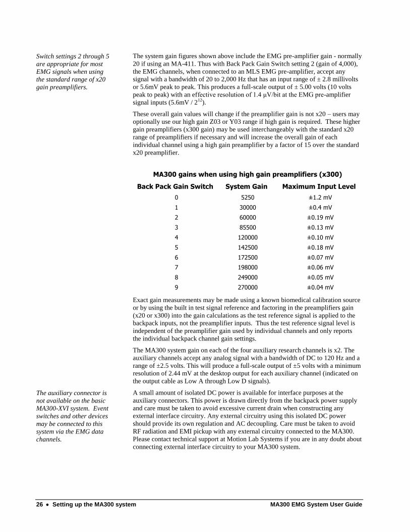
The system gain figures shown above include the EMG pre-amplifier gain - normally
20 if using an MA-411. Thus with Back Pack Gain Switch setting 2 (gain of 4,000),
the EMG channels, when connected to an MLS EMG pre-amplifier, accept any
signal with a bandwidth of 20 to 2,000 Hz that has an input range of ± 2.8 millivolts
or 5.6mV peak to peak. This produces a full-scale output of ± 5.00 volts (10 volts
peak to peak) with an effective resolution of 1.4 μV/bit at the EMG pre-amplifier
signal inputs (5.6mV / 212
).
These overall gain values will change if the preamplifier gain is not x20 – users may
optionally use our high gain Z03 or Y03 range if high gain is required. These higher
gain preamplifiers (x300 gain) may be used interchangeably with the standard x20
range of preamplifiers if necessary and will increase the overall gain of each
individual channel using a high gain preamplifier by a factor of 15 over the standard
x20 preamplifier.
MA300 gains when using high gain preamplifiers (x300)
Back Pack Gain Switch System Gain Maximum Input Level
0 5250 ±1.2 mV
1 30000 ±0.4 mV
2 60000 ±0.19 mV
3 85500 ±0.13 mV
4 120000 ±0.10 mV
5 142500 ±0.18 mV
6 172500 ±0.07 mV
7 198000 ±0.06 mV
8 249000 ±0.05 mV
9 270000 ±0.04 mV
Exact gain measurements may be made using a known biomedical calibration source
or by using the built in test signal reference and factoring in the preamplifiers gain
(x20 or x300) into the gain calculations as the test reference signal is applied to the
backpack inputs, not the preamplifier inputs. Thus the test reference signal level is
independent of the preamplifier gain used by individual channels and only reports
the individual backpack channel gain settings.
The MA300 system gain on each of the four auxiliary research channels is x2. The
auxiliary channels accept any analog signal with a bandwidth of DC to 120 Hz and a
range of ±2.5 volts. This will produce a full-scale output of ±5 volts with a minimum
resolution of 2.44 mV at the desktop output for each auxiliary channel (indicated on
the output cable as Low A through Low D signals).
The auxiliary connector is
not available on the basic
MA300-XVI system. Event
switches and other devices
may be connected to this
system via the EMG data
channels.
A small amount of isolated DC power is available for interface purposes at the
auxiliary connectors. This power is drawn directly from the backpack power supply
and care must be taken to avoid excessive current drain when constructing any
external interface circuitry. Any external circuitry using this isolated DC power
should provide its own regulation and AC decoupling. Care must be taken to avoid
RF radiation and EMI pickup with any external circuitry connected to the MA300.
Please contact technical support at Motion Lab Systems if you are in any doubt about
connecting external interface circuitry to your MA300 system.

MA300 EMG System User Guide Setting up the MA300 system 27
Working with C3D files
EMG data in C3D files is
often created when an
EMG system is connected
to an Analog to Digital
Convertor (ADC)
controlled by a 3D motion
capture system or other
data recording system like
the Dataq WINDAQ.
Many MA300 systems are used with motion capture systems that use C3D files to
store the recorded EMG information together with force data and 3D trajectory
information. The analog data within C3D files can be calibrated by storing an analog
scale parameter for each analog channel. This scale factor is usually calculated to
report either the data in terms of “volts applied to the ADC inputs” or, the data
values actually measured by the device. The scale factors that are discussed in this
section are simply numbers that are used in the mathematical formulas shown here to
allow you to convert the recorded EMG data into some form that can be easily
discussed and analyzed. Most people find it much easier to think of the actual EMG
signal in terms of micro-volts at skin surface (or percentage MVC) rather than the
more technical digital sample values or Volts produced by an EMG system.
The following discussion assumes that the reader is familiar with C3D files, a public
file format used by most 3D motion capture systems and in common use in
biomechanics laboratories worldwide. This section attempts a brief overview – a far
more detailed discussion of the factors affecting C3D scale factors and a full
explanation of the calculation of these scales can be found on the C3D web site at
http://www.c3d.org.
Default C3D scale factors
It is recommended that all
EMG signals in a C3D file
are scaled in terms of
“Volts applied to the ADC
inputs” – normally this will
have a range of ± 5 Volts.
The magnitude of the recorded EMG signal is affected by the ADC hardware as well
as the individual EMG channel gain switch settings. Since the user can change the
individual gain settings for each channel, it is normal to select C3D scale factors that
simply scale the MA300 system output in terms of volts produced by the MA300
system and allow another application to scale the results to take into account the
individual EMG channel gains. This is the recommended C3D scaling method and is
required if the data is to be processed using either the EMG Analysis or EMG
Graphing applications available from Motion Lab Systems.
Assuming an ANALOG:GEN_SCALE factor of 1.00 and an output signal range of
±5 from the MA300, the ANALOG:SCALE factors for each EMG channel are:
12-bit ADC ANALOG:SCALE = 0.002441406
16-bit ADC ANALOG:SCALE = 0.000152588
These values will produce a C3D file with all EMG data scaled to ±5 Volts – this is
the recommended method of scaling EMG data and is required if the EMG data is to
be analyzed using any Motion Lab Systems software application. These applications
contain functions that provide methods of scaling the reported data with respect to
the individual EMG channel gains.
If you scale the EMG channels in volts using either of the above parameter values,
we recommend that you modify the ANALOG:UNITS parameter to “V” to indicate
correct scaling values.
Complete information on the C3D file format, with worked details of analog scale
calculations, and a full manual, is available on the Internet at http://www.c3d.org.
Individual C3D scale factors
Motion Lab Systems DOES
NOT recommend the use of
individual scale factors for
EMG data analysis.
Alternative, the EMG data can be recorded and viewed with the data calibrated in
microvolts (μV) at the skin surface by entering individual scale factors for each
analog channel. The value of these individual channel scale factors (called
ANALOG:SCALE parameters) can usually be determined from to your data

28 Setting up the MA300 system MA300 EMG System User Guide
collection system documentation or calculated from the following formula:
GAIN
SCALEGENBITSCALE
_
The GEN_SCALE value is normally chosen when the analog data collection (ADC)
system is installed. The value of GEN_SCALE is normally preset and affects all
ANALOG:SCALE calculations - it should not be changed without careful
consideration of the effects on any other analog signals recorded in the C3D file. The
BIT value represents the value of 1-bit in Volts and is determined by the
characteristics of the ADC collection system. It can be calculated from the following
formula:
resolution
gainrangeBIT
where range is the ADC input range in Volts, gain is any ADC gain factor that is
applied to the channel, and resolution is the bit resolution of the ADC (i.e. 4096 for a
12-bit ADC or 65536 for a 16-bit ADC). Note that the range value is the full ADC
measurement range - this will have a value of 20 for most common ± 10-volt ADC
systems. When calculating the gain used in this equation you must take into account
the amplification applied to the EMG signal at every stage in the EMG recording and
data collection process – preamplifier, the EMG system, and ADC, It is strongly
recommended that the calculated gain is verified by direct measurement.
An Excel spreadsheet that
calculates all analog C3D
scale factors is available
from Motion Lab Systems.
A table of ANALOG:SCALE parameters is given here to scale the C3D file output
in microvolts at skin surface for GEN_SCALE values of both 0.0048828 and 1.000.
Both these ANALOG:GEN_SCALE values are commonly used with 12-bit ADC
data collection systems that sample data with a ± 10 Volt range.
Note that setting the GEN_SCALE value to 1.00 will result in very small individual
ANALOG:SCALE values that are very small if the users attempts to scale the output
results in terms of microvolts at skin surface. Some software applications may have
problems with interpreting very small ANALOG:SCALE values. The following
values assume that the ADC range is ± 5 Volts (a ± 10 Volts ADC with a gain of x2),
and the ADC resolution is 12-bits:
Gain Switch
ANALOG:SCALE value if GEN_SCALE is 1.000
ANALOG:SCALE value if GEN_SCALE is 0.0048828
0 0.0000070358 0.0014409259
1 0.0000012624 0.0002585322
2 0.0000006226 0.0001275188
3 0.0000004432 0.0000907773
4 0.0000003172 0.0000649690
5 0.0000002631 0.0000538911
6 0.0000002193 0.0000449157
7 0.0000001912 0.0000391482
8 0.0000001477 0.0000302591
9 0.0000001349 0.0000276183
If you enter the appropriate parameter value for the ANALOG:SCALE then we
recommend that you also modify the ANALOG:UNITS parameter to “μV” to
indicate the new scaling values. Complete information on the C3D file format is
available on the Internet at http://www.c3d.org.

MA300 EMG System User Guide Setting up the MA300 system 29
Selecting the EMG frequency bandwidth
The default maximum EMG signal bandwidth for MA300 systems with a variable
anti-alias bandwidth switch is 2kHz, and 1kHz for the systems without the anti-alias
switch.
If your EMG system does
not have an anti-alias
switch then you can skip
this section. All MA300-
XII and MA300-XVI
systems have a fixed
1000Hz EMG bandwidth.
Sometimes the full bandwidth of the MA300 system will be higher than your data
collection or data recording equipment requires, or it may just be higher than you
require for a particular experimental protocol. If you have one of the MA300 models
with an anti-alias bandwidth switch then you can select a lower EMG signal
bandwidth by filtering the higher frequency components of the EMG signals – thus
reducing the bandwidth of the raw EMG signal to a range that is suitable for your
recording system (or experimental protocol) and is essential to eliminate the danger
of signal aliasing (Nyquist sampling errors) that can corrupt the EMG signal.
The anti-alias bandwidth switch controls a high quality, Bessel, variable anti-alias
filter that can be preset by the user to control the bandwidth of the data signals from
the system. A Bessel filter is a variety of linear filter with a maximally flat group
delay (linear phase response) with an almost constant group delay across the entire
EMG signal bandwidth, thus preserving the wave shape of filtered EMG signals
without introducing spurious signals that may affect the EMG frequency spectrum.
This filter allows the user to limit the higher frequency content of the EMG signal to
ensure that the analog recording system is not presented with ‘out-of-band’ signals
that could cause unwanted artifact in the recorded EMG signals when the analog
sampling rate is not high enough. According to the Nyquist sampling theorem the
analog sampling rate should be at least twice the maximum frequency component of
the signal of interest – in this case the EMG signals. In other words, the maximum
frequency of the EMG signal should be less than or equal to half of the ADC system
sampling rate to avoid the introduction of aliasing artifact into the EMG signals that
you wish to record.
The MA300 Anti-Alias Filter
All EMG signals from the backpack are low pass filtered before being transmitted to
the desktop unit. This restricts the highest frequencies available from your MA300 to
levels set by the low pass filter within the backpack. This anti-alias filter will pass all
frequencies lower than the value selected and attenuate all analog signal components
higher than the chosen value.
The variable anti-alias filter available on
some MA300 systems provides seven
different settings at 350, 500, 750, 1000,
1250, 1500, and 2000 Hz and is controlled by
a rotary switch on the backpack unit.
The inclusion of high quality Bessel anti-
alias filters for each EMG channel in the
MA300 systems allows raw signals to be
recorded at the full bandwidth of your analog
recording system. As a result, it is important that the data collection system analog
sample rate is set to a suitable frequency taking into account the bandwidth of all the
signals.
MA300-X systems without
an adjustable anti-alias
filter have a fixed 1000Hz -
3dB bandwidth.
It is essential to filter raw EMG signals before recording to ensure that your data
does not contain any frequencies that your data collection system cannot record.
Basically your ADC sample rate MUST be at least twice as fast as the upper signal
bandwidth. For example, if you are sampling an EMG signal at 1200 samples per
second then you should select the 500 Hz low pass filter. However, if your clinical

30 Setting up the MA300 system MA300 EMG System User Guide
protocol requires EMG signals up to 1000Hz (for instance if you are involved in
fine-wire recording for research purposes) then you should select filter setting 4
(1000Hz) and sample the signal at a minimum of 2000 s/s to ensure adequate signal
quality and avoid the possibility of aliasing artifacts.
Filter Switch EMG Bandwidth Minimum Sample Rate
0 2000 Hz. 4000 s/s
1 1750 Hz. 3500 s/s
2 1500 Hz. 3000 s/s
3 1250 Hz. 1500 s/s
4 1000 Hz. 2000 s/s
5 750 Hz. 1500 s/s
6 500 Hz. 1000 s/s
7 350 Hz. 700 s/s
If you are collecting EMG data for research or you intend to perform frequency
spectrum analysis on the data then you should (whenever possible) set the MA300
system filter switch to “0” and sample the data at 4000 samples per second or higher
for maximum accuracy. If your data collection system has a lower maximum sample
rate then set the filter switch accordingly.
The overall EMG system
bandwidth is set by the
backpack anti-alias filter.
By filtering the EMG signal in this way, before the signal is sampled by your motion
capture or data collection system, you will avoid the problem of “signal aliasing”
that occurs when a signal changes faster than it can be recorded or analyzed. Signal
aliasing can introduce false signals into the sampled EMG that interferes and distorts
the original EMG signal. It is impossible to filter an EMG signal to remove aliasing
artifact after the signal has been recorded so optimal filtering is essential.
The anti-alias filter is set whenever the switch setting is changed – this may
introduce a momentary spike into each analog channel so is important that the anti-
alias switch is only changed prior to recording EMG signals. Changing the anti-alias
filter switch after starting to record an EMG trial is not recommended.
Band-Pass filter option
In addition to the built-in anti-alias filter,
the MA300 offers an optional Band Pass
Filter that allows the user to dynamically
set the High Pass filter frequency (thus
removing most typical motion artifact
signals) and preset a Low Pass frequency
to ensure that the MA300 never produces
analog signals with a higher frequency
content than your data collection system
can sample or record.
The filter can be installed in the EMG
signal path, inside the MA300 desktop
unit, and is powered by the internal
MA300 power supply to eliminate the
possibility of introducing ground loops or
external interference into the EMG signal.
Although the installation is usually done at

MA300 EMG System User Guide Setting up the MA300 system 31
the factory, prior to system sale, instructions are included at the end of this manual to
allow users to add this useful feature to their system after the initial purchase.
If your system does not
have a rotary switch at the
top of the rear panel of the
MA300 desktop unit then
you do not have this option.
The primary function of the optional filter is to restrict the low frequencies that the
MA300 interface unit can output to your data collection or data measurement system.
A high pass filter will, as its name suggests, pass all frequencies higher than a certain
value. You may select this value to 20, 40, 60, 80, 100, or 120 Hz. — a common
setting is 40 Hz for surface EMG recordings. The principal function of this filter is to
reduce the amount of the low frequency artifact (or noise) component of the EMG
signal. This tends to produce EMG signals with a flat baseline that may be easier to
analyze in many gait protocols. The high pass filter frequency is set via a rotary
switch at the rear of the Desk Top Unit.
Figure 4 - Unfiltered EMG (20-800Hz) with significant low frequency artifact signals
All MA300 systems can be
upgraded to include the
filter by purchasing the
optional filter assembly.
The optional filter also contains an additional anti-aliasing filter that may be preset
on installation to a range of frequencies from 300 to 2,000 Hz. This additional filter
can be used to ensure that the output signal from the MA300 system does not contain
any signals that might cause aliasing errors. Setting this internal filter will override
the backpack filter setting and ensure that the system cannot produce any signals
higher than the internal value. This can be set when the system is installed and offers
a wider range of filter points as well as a much steeper roll-off.
Figure 5 - Filtering the EMG signal (80-350Hz) to remove artifact produces cleaner data.
The effects of filtering the EMG signal are shown in Figure 3 (unfiltered) and Figure
4 (filtered). Both illustrations are the same signals from a fine wire recording of the
Tibialis Anterior muscle.
The filter does not apply to
the research channels that
are available on the 16-
channel system, nor does
the filter apply to the event
switch channels, which are
processed separately.
The illustration shows the original sampled EMG data, recorded at 1600 samples per
second. This means that the analog data can contain frequencies as high as 800 Hz.
The result of filtering the original EMG signal with a band-pass filter set at 80 Hz to
350 Hz are shown in Figure 4. These illustrations were generated using Motion Lab
Systems EMG Analysis software together with the C3Deditor analog filter.
Demonstration copies of these software packages can be downloaded from the
motion lab systems web site at http://www.motion-labs.com at any time.
It is important to note that applying a filter to the MA300 signal path will filter all
signals passing through the EMG channels in the MA300.
If you intend to perform an electrical specifications test of the MA300 system EMG
channels with a device such as the Whisper EMG Test Set then we recommend that
low-pass filter in the backpack and the high-pass and low-pass filters in the optional
internal band-pass filter are set to their minimum effective settings (20Hz HP and
2kHz LP) and that data is sampled as fast as possible (at least 4,000 sample per
second per channel) to reproduce the test signal as accurately as possible.
The four auxiliary research channels
The auxiliary channels are All MA300 systems, except the MA300-XVI, include an additional four channels

32 Setting up the MA300 system MA300 EMG System User Guide
not affected by the optional
filter or the anti-alias filter
setting.
that can be used for low frequency signals. These four channels have a bandwidth of
DC to 120 Hz which makes them ideal for many research applications that require a
DC frequency response such as event switches, goniometers, EKG, respiration, and
oxygen consumption to list only a few of the possible applications. The low pass
frequency response of these channels is fixed at 120 Hz. Any input signals above 120
Hz will be attenuated and will not appear at the output of the MA300. Inputs to all
four channels are through a pair of input connectors – one on each side of the
backpack and must be within the range of ±2.5 Volts. A small amount of isolated DC
power may be drawn from the subject backpack to power any external interface
circuitry or can be used to record event switch signals with an appropriate current
limiting resistor.
Please contact Motion Lab Systems if you require a cable to interface to these
channels. Goniometers can be connected via a Goniometer Interface Box (GIB)
available from Motion Lab Systems.
Event switch signals
MA300 systems with dedicated event channels support the use of up to a total of
eight (8) event switches to record gait events such as heel-strike and toe-off. The
dedicated event switch interface is designed to work with our standard MA-153
event switch, FSR’s (Force Sensitive Resistors), or any common switch device. All
event switch inputs are fully “de-bounced” in the subject backpack.
The state of each of the eight (8) event switches (open or closed) is encoded in the
dedicated event switch interface and sent to the interface unit as digital signals in
ensure signal integrity. On arrival at the MA300 desktop interface unit the event
switch output is transformed into two analog outputs that encode the state of four
event switches each (left and right feet) as 16 discrete DC levels for each analog
event signal output. Note that there is no requirement to use all eight (8) event
switches. If your application only requires heel and toe contact information to define
a gait cycle then just use two (2) event switches and disconnect the unused event
switches. The system will ignore the unused inputs, which will be treated as “open”
switches.
Figure 6 - A typical analog event switch signal indicating multiple switch closures.
The event channels can
record any type of binary
(on or off) event to indicate
By encoding four switches onto a single analog channel the user is only required to
record or monitor a total of two analog channels to observe the state of all eight (8)
event switches. Each of the two analog event switch output channels is at zero volts

MA300 EMG System User Guide Setting up the MA300 system 33
an EMG activity timing
period – on or off, up or
down, hit or miss etc.
when all four of its event switches are open. When any one of the four (4) event
switches closes, the appropriate analog event switch channel output voltage will
increase by an amount determined by the closing switch. Each switch changes the
output by a unique value.
This system works because each of the four (4) event switches (left or right side)
adds a different DC voltage to its appropriate analog event switch output. When the
Heel event switch closes a DC level of 2.500 volts will appear on the analog output
for that channel (right or left). Closing the next event switch (generally the fifth
metatarsal) will add 1.250 volts to this signal. Thus, the output channel will be at
3.750 volts; the other event switches (first metatarsal and toe) will add 0.625 and
0.313 volts respectively.
By adding the four different voltages, each event switch channel can display the full
range of 16 different event switch states. If all four switches are closed, a maximum
voltage of 4.688 volts will be seen on the analog output of the event channel. A table
of all 16 combinations is shown in appendix A, at the end of this User Guide. Please
contact Motion Lab Systems technical support if you need further explanation of this
feature.
Event switch sensors
Ten (10) event switches supplied with MA300 systems that support dedicated event
channels (MA300-18, -22 and -28). These switches will turn on when a pressure of
approximately 50-100 grams of pressure is applied. They can be tested by connecting
them to the backpack (via the supplied cable) and pressing them between two fingers
while watching the front panel indicator lights. Since the sensors are small, they
require a little care in placing the sensors in the right position to record the
appropriate event/floor contact. Usually a few practice sessions on a willing subject
are all that is necessary to enable you to attach the sensors quickly and accurately.
Figure 7 - A standard Motion Lab Systems event switch.
The sensors each have a two-pin connector on a lead - this connector is designed to
make a reliable electrical connection yet disconnect easily should any force be
applied to the connection to avoid damage to the sensors. The connector should mate
with an event switch cord (sold in packs of eight - Motion Lab Systems part number
MA-136) that plug into the event switch cable from the subject backpack. The event
switch cable plugs into the subject backpack and has a connector housing at one end
that connects to the event switch cables. This housing should normally be taped to
the subject’s ankle so that the event switch cords and switches can be easily placed to
provide the most reliable signals while interfering with the subjects gait as little as
possible.
The MA300-X systems do not have dedicated event channels. Event switches are
supported on these systems via direct connection to the EMG signal inputs (one
switch per EMG channel connector) or into the auxiliary channels on the MA300XII
system (two switches per auxiliary connector). Event switches that are connected to
the auxiliary channels or the EMG channels do not indicate their status via the DTU
front panel lights.


MA300 EMG System User Guide System Displays 35
System Displays
Signal Displays The MA300 desktop unit provides three system status
indicators grouped together at the bottom of the front
panel. These are two yellow LED indicators that show
possible fault conditions and a green LED indicator that
should always be illuminated when the system is turned
on, indicating that the AC power is connected and the
DTU power supply is functioning. Eight individual
green LED indicators at the top of the unit display the
status of the dedicated event switch event switch
channels available on some MA300 backpacks. These
lights enable you to immediately check the functioning
of event switches connected to the subject via the
dedicated event channels.
System Status
The two yellow LED indicators are labeled “No Sig.”
and “CRC”. The yellow “No Sig.” LED will illuminate
when the desktop interface unit is not receiving a digital
signal from the backpack. This would be quite normal if
the pack-back were disconnected from the deck-top
interface. However, error condition exists if the LED
indicator comes on while the backpack is connected. A
faulty coaxial interconnecting cable or an internal fault
within a system component could cause such an error
condition.
The yellow “CRC” LED indicator will be illuminated if
the internal digital error checking circuitry detects an
error in the incoming signal. The “CRC” light should
not be illuminated when the MA300 system is used with
a coaxial cable but will light when the radio telemetry
option is used. The “CRC” light indicates the small
errors of one or two bits in the data signal are bring
corrected by the circuitry within the interface unit.
If either of the yellow LED indictors is lit when using a coaxial cable to connect the
back pack and desk top units you should check the cable connecting the backpack to
the desktop unit and contact Motion Lab Systems to discuss the repair of the system.

36 System Displays MA300 EMG System User Guide
Event switch indicators
There are eight green event switch activity indicators at the top of the interface front
panel that indicate the status of the dedicated event channels that are available on
some MA300 backpacks. Each activity indicator lights when its associated event
switch closes and, during normal gait (heel, 5th, 1st metatarsal and toe sequence),
you will see the indicators light in a moving bar from heel to toe. These lights also
enable the user to test each event switch individually and quickly find and replace
faulty event switches at any time.
These indicators do not indicate the status of event switches connected to EMG or
auxiliary channels on MA300 backpacks when the dedicated event channels are not
used.
Backpack indicators
There are only two indicators types on the backpack. These are green PWR indicator
that should always be on when the system is operating and blue LED indicators
associated with each EMG channel gain control that light whenever the associated
channel signal approaches an overload condition. The blue overload LED indicators
will light whenever its associated EMG input is within 5% of its maximum operating
level. As a result, it is normal for them to light occasionally during use but they
should not be continuously lit as this would indicate that the associated EMG
channel gain is too high.
The green LED indicator show always be lit – this indicates that the backpack is
receiving isolated DC power from the desktop unit.
Fault Detection and Troubleshooting The MA300 systems are very reliable but if you experience any problems then the
following hints may prove useful. Always return any faulty units to Motion Lab
Systems or a qualified biomedical engineer for internal repairs.
You can always contact Motion Lab Systems to discuss any potential problems with
any of our products regardless of the warranty status or age of the product. There is
no charge for contacting Motion Lab Systems to discuss a service or support issue.
Note that it is normal for all the indicator lights to flash ON briefly when AC power
is first connected to the system or when the subject backpack is connected to the
system or cable.
The Display Unit No Sig
light is on.
There is no signal coming from the backpack. Check that the backpack is connected
and the green backpack DC OK light is on. If it is OFF then you probably have a
broken coaxial cable — replace the cable with a spare and schedule the broken cable
for repair as soon as possible. Contact Motion Lab Systems if this indictor remains
on after replacing the coaxial cable. Return the unit to your distributor or biomedical
engineering department for service.
None of the front panel
lights are on.
Is the power switch on? Check the line cord and fuse — at a minimum the green
POWER light should be on to show that AC power is applied to the unit and the DC
Power Supply is operational. The internal power supply is auto-sensing and will
select the correct AC voltage range - no user adjustment is required. Contact Motion
Lab Systems if none of the indictors light when AC power is connected and the
desktop is turned on. Return the unit to your distributor or biomedical engineering
department for service.

MA300 EMG System User Guide System Displays 37
The CRC light is on but
the No Sig light is off.
Check that the backpack is connected to the system via the coaxial cable for testing.
If the backpack is connected and appears to be functioning then you may have an
internal fault in the system. The CRC light shows that the digital signal channel is
generating an error. Contact Motion Lab Systems if this indictor remains is on while
the backpack is connected to the system. Return the unit to your distributor or
biomedical engineering department for service.
The blue LED indicators
on the backpack are ON
although the subject is
inactive.
Select a lower channel gain for the associated EMG channel - if the light does not
extinguish then you may have a defective EMG pre-amplifier. Check that the pre-
amplifier has been applied correctly – if you cannot see what the problem is then
replace it with a spare and test it later.
The software package used
to analyze the EMG signals
from the MA300 does not
find the correct gait cycles.
Check that the analog event switch signals are assigned correctly so that the left side
EMG signals are being analyzed with the event switches on the correct event. Read
your EMG analysis software manuals to determine how the software determines gait
cycles. Contact Motion Lab Systems technical support if you cannot resolve the
problem.
The EMG signals recorded
are very small although the
blue indicators on the
backpack show that large
signals are being recorded.
Check that your ADC sampling system gain is set correctly to match the input level
expected by your ADC recording system. Typically when you have this problem you
will find that the ADC sampling system has been set to respond to a ±10 Volts (i.e.
20 Volt range) signal. If in doubt, use an oscilloscope to confirm the MA300 output
levels. The correct analog signal range for all MA300 signals is ±5 Volts for all
EMG and event switch channels.
The recorded EMG signal
appears to be distorted,
with EMG activity that
doesn’t match the expected
signal.
Check that the analog sample rate of the Motion Capture or recording system is fast
enough – MA300 systems without the anti-alias bandwidth filter must be sampled
with a rate of at least 2000 samples per second while the sample rate for the MA300
systems with the anti-alias switch will depend on the setting of the anti-alias filter.
The analog sample rate must be at least twice the anti-alias filter setting to avoid
aliasing errors in the recorded signal.
The system is functioning
but no EMG is recorded on
any external device.
Check the connecting cable with an oscilloscope to ensure that the cable is correctly
connected and that EMG signals are present at the input of the ADC sampling
system.
Some EMG channels work
but others do not have any
EMG signals.
Check the analog signal connections from the back of the MA300 desktop unit
through to your measuring/recording system. Almost all ‘lost channel’ complaints
are due to problems with the analog signal cables and connectors. If this does not
cure the problem then record an example file (C3D format if possible) and send it to
Motion Lab Systems for analysis.
The system appears to be
functioning but the signals
recorded are very large or
very small compared to
another EMG system such
Check the settings of the gain switches for the channels that appear to have
problems. Increase the gain for any low level signals by turning the gain switches
clockwise to higher numbers, decrease the gain by turning counter clockwise to
select a lower number on the gain switch.

38 System Displays MA300 EMG System User Guide
as the MA-100.
The MA300 system appears
to be functioning but ALL
of the EMG is recorded
with very large amounts of
noise and AC interference.
Check the connecting cable with a multi-meter to ensure that there are no broken
connections. Check that the signal return (output pin #17) is connected correctly and
that you are not using the Chassis Ground (output pin #25) as a signal ground.
If you have noisy data use a disposable electrode to provide a ground reference.
Apply the electrode to the subject skin surface and connect to the safety DIN
connector adjacent to the coaxial cable connector on the subject backpack.
Use an oscilloscope to measure the signal present at the MA300 analog output
connector with the unit turned on and connected to the backpack but without any
EMG pre-amplifiers connected to the backpack. The AC noise component of the
output signal should be less than 10mV (a small DC offset may be present). Signals
greater than 10mV may indicate a grounding problem or a fault within the MA300
EMG system. Check that you are recording/sampling the EMG at a high enough
sample rate and send a sample data file (C3D format if possible) to Motion Lab
Systems for review.
The MA300 system appears
to be functioning but some
of the EMG is recorded
with noise and AC
interference in the signal.
When some EMG channels are noisy but other EMG channels appear fine this
always indicates a problem with either the pre-amplifiers or the electrode/skin
interface on the subject.
Test the preamplifiers on the problem channels - do they produce a good recording
on another muscle? If so the then problem is poor skin contact at the original
electrode site – either the preamplifier electrodes are not making good mechanical
contact with the skin or else the skin is dry and a poor signal conductor. Rubbing a
very small amount of electrode gel or a water based hand lotion into the skin will
almost always improve the signal if the skin is dry and/or flaky.
Intermittent problems are usually a result of broken wires – commonly at either the
backpack connector or the entry into the preamplifier body. In this case return the
preamplifier for repair.

MA300 EMG System User Guide Using the MA300 39
Using the MA300
Connections
Each MA300 system consists of a backpack, carried by the subject using one of the
belts or jackets supplied, and a desktop interface unit. These two units are connected
by means of the lightweight coaxial cable supplied with the system or via the radio
telemetry option. The backpack comes with EMG pre-amplifiers (six, eight, ten or
sixteen - depending on the model in use), a coaxial connecting cable, and an analog
signal cable together with a belt or jacket to support the backpack during use.
MA300 backpacks that support the dedicated event channels are also supplied with
event switch connection cables, and event switches. Event switches are optional
with the MA300 EMG systems that lack the dedicated event channels.
The subject backpack
The backpack unit (BPU) has two rows of connectors
on either side of the casing that provide connections
for the EMG pre-amplifiers and, depending on the
type of backpack, auxiliary research channels and
the event switches. Some MA300 backpacks
have eight dedicated event channels via two 5-
pin LEMO connectors, one on each side of the
backpack. The EMG and auxiliary research
connectors will vary depending on the
options selected when the system was
purchased – these can be either 4-pin LEMO
or 4-pin BINDER connectors.
There are no subject connections or user adjustments inside the backpack cover – all
connections and controls are accessible without opening the backpack.
Each side of the backpack will have a number of EMG connectors – three, four, five
or eight, depending on the backpack model. The EMG inputs are numbered with
odd channels on the left side of the backpack and even numbered channels on the
right side. In addition to the EMG channels, each side of the backpack may have a
connector for two auxiliary research channels and four event switches. You should
not connect any EMG pre-amplifiers to either of these inputs.
The subject backpack has a number of miniature LED indicators. The green POWER
light should be on whenever the pack-pack is connected to the interface unit and
shows that DC power is supplied to the system and the internal power supplies are
functioning correctly. In addition to the power light, each EMG channel has a blue

40 Using the MA300 MA300 EMG System User Guide
LED indicator that will flash if the associated EMG signal is within five percent of
an overload condition. Flashing occasionally during an experiment is normal for
these lights as brief peaks of muscle activity occur during contractions.
In the center of the subject backpack are two rows of gain controls switches. These
allow the user to vary the gain of the individual EMG channels to optimize the signal
levels. Each control is a ten-position switch that changes the channel gain, allowing a
wide range of signal input levels. Each control can be easily adjusted with a small
flat-blade screwdriver.
The TEST push button, below the gain switches, is recessed to prevent inadvertent
operation. When this button is depressed as standard test signal is applied to all of
the EMG channels allowing the system to be calibrated so that the gain used for each
channel can be automatically recorded.
Some backpacks include a variable low pass filter – this is marked “Anti-Alias
Bandwidth” and should be set to the desired EMG signal bandwidth prior to
recording any EMG signals.
The interface unit
When the coaxial cable is disconnected from the desktop interface unit
(DTU), you will notice that the No Signal and CRC Error lights on
the desktop interface unit are ON. This is normal. Both lights
should be extinguished whenever the backpack unit is connected
to the desktop interface unit via the coaxial cable.
Whenever an event switch, connected to a dedicated event
channel closes, the green LED indicator associated with that
event switch will light on the front
panel. There are a total of eight
event switch indicators, one for
each switch circuit, so that up
to eight dedicated event
switches may be monitored
simultaneously. Note that
although the system can
monitor up to four switches on each
event, few software packages require all four switches for gait analysis. If all you
require is gait timing information then you may find that you only need the heel
switch to provide basic gait cycle information. Dedicated event switch channels are
a feature of some MA300 backpacks while other backpacks support event switches
via the auxiliary or EMG data channels which are not monitored on the DTU front
panel.
The EMG pre-amplifiers
The standard preamplifiers
supplied with the MA300
system have a gain of x20.
Motion Lab Systems offers a range of different preamplifiers to accommodate almost
any EMG data collection requirement so it is important to select the correct type of
preamplifier for the subject and data collection conditions. MA300 systems are
available with a range of preamplifiers – normally our standard MA411 surface
preamplifiers are supplied but systems may include several different preamplifier
types. Each type of preamplifier is available with either LEMO or BINDER
connectors – if you order additional preamplifiers at any time then you should make
sure that you request the correct type of connector for your system. LEMO
connectors have a metallic case while BINDER connectors are black plastic. All
preamplifiers have similar specifications.

MA300 EMG System User Guide Using the MA300 41
MA411 preamplifiers are high performance EMG amplifiers
with two sensor disks separated by a single ground
reference bar. These preamplifiers are easy to
use and can generally be quickly strapped or
taped over any surface muscle on the limbs.
They do not require gel and work well even on
moderately hairy subjects without requiring
shaving or extensive skin preparation. These
preamplifiers can usually be used without a separate
ground reference electrode although we recommend a
ground reference electrode if AC line noise is a
problem.
The MA411n preamplifier style is identical to the MA411 but lacks
the central ground reference bar and requires that a separate ground reference
electrode is used. This preamplifier style is preferred in some situation where high
levels of static or AC line noise is a problem.
The MA416 preamplifier is designed for use with fine-wire electrodes and has two
thumbscrews that can be used to connect fine-wire electrodes. These preamplifiers
require a separate ground reference electrode to avoid AC line interference problems
in the recorded EMG signal. MA416 preamplifiers are designed to withstand the
stimulation pulses produced by any muscle stimulator, allowing the electrode
placement to be verified after wires are connected to the preamplifier.
The MA420 preamplifiers feature a waterproof body and standard “snap lead”
connections for use with many different types of disposable gel
silver/silver-chloride (Ag/AgCl) electrodes. This
preamplifier style can be used anywhere on the body but
is particularly suitable for upper body work or any
situation where perspiration or moisture is a
problem.
It is generally best to attach the backpack
behind the subject using the jacket or belt
provided with the system although some data
collection protocols may require that the
backpack is mounted on the chest. Additional
belts and jackets in different sizes may be
ordered from Motion Lab Systems as required.
Once the backpack has been fixed to the subject
you can attach the EMG pre-amplifiers to the
subject. Note that there is no need to have the backpack
connected to the coaxial cable from the interface at this stage. It can be connected at
any point before the collection of data - you do not need to switch off the interface
unit when you connect or disconnect the backpack or attach the EMG pre-amplifiers
to the subject. Many people use our small plastic bead markers on the individual
preamplifiers cables identify individual pre-amplifier leads. Each bead marker clips
over the pre-amplifier cable and identifies the cable by color and can help ensure that
each preamplifier is connected to the correct channel.
Surface EMG
If the skin surface appears dirty or greasy then you will need to “prep” the surface
with an alcohol soaked cleaning swab. When you have found (or land marked) the
correct position for the pre-amplifier on the muscle you should tape the pre-amplifier
in place using Micropore® or similar hypoallergenic tape to hold the preamplifier in

42 Using the MA300 MA300 EMG System User Guide
place on the muscle. The preamplifier can then be wrapped
tightly against the muscle by a length of Coban® or similar
sports wrap – make sure that you use Latex free tape if you
anticipate that your subject may be Latex sensitive. The
additional wrap of Coban® will hold the preamplifier disks
tightly against the skin surface and ensure that they do not
move during the EMG tests as unwanted motion over the
skin surface will cause low frequency noise to appear in
the EMG signal. If the pre-amplifier has been applied
properly then you should see two circles impressed into
the skin when the pre-amplifier is removed at the end of
the session. These marks will generally fade within 10 to
20 minutes. Subjects with particularly sensitive skin or
freshly shaved areas may find that the marks last up to
24 hours.
It cannot be stressed too much that this is the most critical
stage in the preparation of the subject if you are to obtain
high quality EMG recordings. Surface pre-amplifiers will
provide good signals from most of the muscles involved in
gait if sufficient care is taken in preparing the subjects skin
and applying the pre-amplifiers.
It is most important to make sure that the preamplifiers
cannot move of the surface of the skin as the subject walks or
moves. All motion artifact problems with MA300 systems can be traced to noise
generated by the movement of the preamplifier on the surface of the skin during the
recording. Likewise AC line noise problems are either caused by a faulty
preamplifier or electrode contact issues where one electrode disk is not making a
good connection with the subject. The digital nature of the MA300 system
eliminates the possibility of recording motion artifacts from cable motion, radio
frequency noise, or electromagnetic fields.
Fine Wire EMG
EMG preamplifiers
manufactured by Motion
Lab Systems Inc., are fully
protected from accidental
static discharge and cannot
be damaged by muscle
stimulators.
If you are using fine-wire electrodes (sometimes called “needle electrodes”) then the
wire should be inserted into the muscle by a qualified therapist or doctor and the
insertion needle removed. If you want to stimulate the muscle to check the electrode
insertion then this may be done after the wires are connected to the EMG pre-
amplifier. The Motion Lab Systems pre-amplifiers contain protection circuitry that
ensures that they cannot be damaged by muscle stimulation signals so you can easily
stimulate a muscle once the wire electrode has been inserted and connected to the
preamplifier.
Commercial fine-wire electrodes are always supplied in sterile packaging and should
be ‘ready to use’ however, if you are making your own fine-wire electrodes you may
find that your need to remove the insulation from the ends of the wire that will
contact the EMG pre-amplifier. This can be done either with a strip of abrasive paper
or with a flame as the insulation will usually vaporize easily.
Motion Lab Systems MA416 preamplifiers are supplied with a set of nylon
thumbscrews which are ideal for attaching both fine-wire or disposable gel
electrodes. Options available for the MA416 preamplifier include pairs of springs
contacts or medical-grade stainless steel thumbscrews that allow direct stimulation of
indwelling fine wire electrodes.
You may also use a disposable subject ground electrode connected to the backpack
unit ground reference socket by the coaxial cable connection. This helps to maintain
the pre-amplifier common mode rejection ratio or C.M.R.R. (i.e., it helps keep the

MA300 EMG System User Guide Using the MA300 43
noise and hum levels low). The backpack connection will accept most standard
disposable monitoring electrodes with an IEC-60601 ‘TouchProof’ connector that
meets the performance standard for Electrode Lead Wires and Patient Cables, in
Title 21 Code of Federal Regulations (CFR), part 898.
Figure 8 - fine-wire electrode prepared for insertion into the muscle.
The EMG pre-amplifiers supplied with the MA300 should last a long time in regular
use. With care, especially in the removal of the pre-amplifier from the subject after
the experiment, they may last many years. If the pre-amplifiers are abused by pulling
them from the subject by their leads then their life will be considerably shortened.
Replacement EMG pre-amplifiers are available through your local distributor, or
directly from Motion Lab Systems Inc. Please note that Motion Lab Systems
provides only a thirty-day warranty on the pre-amplifiers and event switches and that
this warranty does not cover normal wear and tear or abuse.
Using Fine-wire Electrodes
Check the expiration date on the fine-wire needle packaging and verify that the fine-
wire sterilized packaging is intact. Follow local site procedures and discard any
packages that have expired, or are not sealed and intact.
Prepare the subject for the insertion by cleaning and sterilizing the insertion area as
appropriate for the intended test, taking all necessary precautions to prevent infection
and or contamination.
Packs of 10 ‘Ready-to-Use’
sterile fine-wire electrodes
are available from Motion
Lab Systems with 30mm
and 50mm cannulas.
Remove the fine-wire electrode from the package and visually inspect both ends of
the electrode wire without touching or contaminating the wires or needle. This may
require holding the electrode against a light surface under a bright light and using a
magnifying glass. Both of the hooked ends should be insulated to within 2mm of the
tip with the remaining wire being exposed - the bare ends should be staggered, not in
contact with each other, and snug against the point of the needle. There should be no
kinks throughout the length of the wire that might cause the wire to break when
removed from the subject after the test. The opposite ends of the wires should have
approximately 6mm of uninsulated, exposed wire for connection to the recording

44 Using the MA300 MA300 EMG System User Guide
interface.
Refer to your anatomical guides as appropriate, locate the desired insertion point and
insert the needle into the muscle smoothly to the desired depth to place the hooked
wires into the target muscle.
Carefully withdraw the needle, leaving the fine-wire pair in place within the muscle
and connect the un-insulated, free ends of the wires to the inputs of your recording
system. Use small pieces of tape to secure the wires at the insertion site and against
the skin to minimize any movement of the wires, or strain at the insertion point
during testing. This helps to minimize signal artifact and noise.
You may optionally check the wire placement within the muscle by applying a
stimulation pulse using a suitable approved nerve stimulation device. Always start
with a low stimulation level and gradually increase the level while observing the
target muscle - if the wire is placed correctly then a small twitch will be observed in
the correct muscle when it is stimulated. Motion Lab Systems pre-amplifiers can
withstand stimulation pulses without problems but if you are using another system
then you should check with the manufacturer to ensure that a stimulation pulse will
not damage their equipment.
Connect an external ground reference electrode to the subject and perform the EMG
test, visually monitoring the EMG signal quality during the test if at all possible.
After the EMG test has been completed, the recording equipment should be
disconnected from the subject. The fine-wire electrode wires can then be removed
with a gentle, smooth and steady pull. This will usually bring the electrodes out
painlessly as the wires are so fine and delicate that they offer little resistance to their
removal.
Immediately inspect the wires after removal to ensure that the wires have been
removed intact from the subject - the wires are nominally 200mm in length
±3.125mm. Occasionally small parts of the wire will remain in the muscle after a
test but provided that the wire fragments are small (less than a couple of millimeters)
this is not normally a cause for concern.
Swab the wire removal site with a sterilizing solution, apply a suitable sterile
covering if necessary and dispose of the used needle and wires in accordance with
local safety policies.
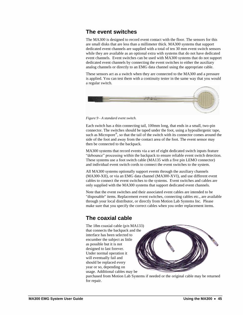
MA300 EMG System User Guide Using the MA300 45
The event switches
The MA300 is designed to record event contact with the floor. The sensors for this
are small disks that are less than a millimeter thick. MA300 systems that support
dedicated event channels are supplied with a total of ten 30 mm event switch sensors
while they are available as an optional extra with systems that do not have dedicated
event channels. Event switches can be used with MA300 systems that do not support
dedicated event channels by connecting the event switches to either the auxiliary
analog channels or directly to an EMG data channel using the appropriate cable.
These sensors act as a switch when they are connected to the MA300 and a pressure
is applied. You can test them with a continuity tester in the same way that you would
a regular switch.
Figure 9 - A standard event switch.
Each switch has a thin connecting tail, 100mm long, that ends in a small, two-pin
connector. The switches should be taped under the foot, using a hypoallergenic tape,
such as Micropore®, so that the tail of the switch with its connector comes around the
side of the foot and away from the contact area of the foot. The event sensor may
then be connected to the backpack.
MA300 systems that record events via a set of eight dedicated switch inputs feature
“debounce” processing within the backpack to ensure reliable event switch detection.
These systems use a foot switch cable (MA135 with a five pin LEMO connector)
and individual event switch cords to connect the event switches to the system.
All MA300 systems optionally support events through the auxiliary channels
(MA300-XII), or via an EMG data channel (MA300-XVI), and use different event
cables to connect the event switches to the systems. Event switches and cables are
only supplied with the MA300 systems that support dedicated event channels.
Note that the event switches and their associated event cables are intended to be
"disposable" items. Replacement event switches, connecting cables etc., are available
through your local distributor, or directly from Motion Lab Systems Inc. Please
make sure that you specify the correct cables when you order replacement items.
The coaxial cable
The 18m coaxial cable (p/n MA133)
that connects the backpack and the
interface has been selected to
encumber the subject as little
as possible but it is not
designed to last forever.
Under normal operation it
will eventually fail and
should be replaced every
year or so, depending on
usage. Additional cables may be
purchased from Motion Lab Systems if needed or the original cable may be returned
for repair.

46 Using the MA300 MA300 EMG System User Guide
The coaxial cables supplied with the system use industry standard RG-174U coaxial
cable. A standard cable is 18 metres long although this length is not critical and
cables may be assembled with nonstandard lengths between 2 and 35 metres. Each
cable uses identical coaxial LEMO connectors at each end.
The condition of the
coaxial cable is easily
checked with an ohmmeter.
The cable is a simple coaxial cable and can be tested for continuity with any
common ohmmeter – normal cables will have low impedance from one end to the
other (5-10 ohms is normal). There should be a very high impedance (greater then
one million ohms) between the inner conductor (central LEMO connector pin) and
outer shield (LEMO connector case).

MA300 EMG System User Guide Making an EMG recording 47
Making an EMG recording
Getting started Your MA300 EMG system can be used to collect EMG signals in a variety of
situations and as a result it is not practical or very useful to try to provide instructions
at this point for the system under all conceivable circumstances. Therefore this
chapter will describe the use of the system in a single setting — that of a Gait or
Motion Analysis Laboratory. We assume that by this stage the MA300 has been
connected to a computer or other recording device and that the system has been
tested to check that everything is working.
Figure 10 - Typical MA300 raw EMG recordings from human gait
The usual procedure in Gait Testing is to have the subject walk, several times, in a
straight line over a distance of four to seven meters (roughly 10-20 feet) while their
movement is recorded for later viewing or processing. Information from force plates
and 3D trajectory data may also be collected simultaneously when the EMG system
is used in a Gait Laboratory.
Start the subject from the end of the walkway or data collection area and ask them to
walk as they would normally - let the subject reach their normal walking speed
before you start to record any data. Since they will be trailing the MA300 coaxial
data cable behind them it is often useful to tape two colored arrows at either end of
the walkway — these serve to show the subject which direction you would like them
to turn so that they clear the trailing cable as they return down the walkway. You can

48 Making an EMG recording MA300 EMG System User Guide
use green tape at the start line and red at the stop line - the subject will rarely notice
the trailing cable at all and these arrows will help eliminate any unnecessary tangles.
If you are planning to record kinetic data from a force plate while you record EMG
then you may find it convenient to place several different colored "start" lines at
about six inch intervals to enable you to adjust the subjects starting position to obtain
a good force plate strike with one foot. In this case you may have to walk the subject
several times at the start of the test to decide the correct starting line so that they
have a good chance of hitting the force plate cleanly with a single stride.
Subject Preparation
Remove preamplifiers from
unused EMG channels if
possible. There’s no need
to use all of the available
channels if they are not
required for the study.
The preparation for EMG testing should always begin before the arrival of the
subject. You will need to decide where to place preamplifiers and whether the study
will be bilateral or unilateral. Using a single MA300 you can study between six and
sixteen individual muscles (depending on the model that your lab has purchased) and
although the MA300 subject backpack is marked on the assumption that you will
record a number of muscles of each side of the body, this is not fixed in any way.
If you are also taking kinematic data with a Gait Analysis system then you will also
need to prepare the marker sets (usually small
retro-reflective balls) that you will be using.
Always test your system (MA300 and
kinematic collection if used) before the subject
arrives — any problems are much easier to
diagnose and fix before the testing starts.
The muscles that will be monitored during your
study are dependent on the diagnosis of the
subject and the extent of lower limb
involvement. It is best if a decision about
which muscles are going to be evaluated is
made before the arrival of the subject — often
this is done by, or in consultation, with the
physician. You may find it useful to set up a
muscle protocol to be monitored for each
different diagnosis but use this as a guide only
as each subject will be different. Some typical
examples of diagnosis related protocols for a
ten-channel MA300 might be:
Spastic Diplegia - Five muscles on each limb - Tibialis Anterior,
Gastrocnemius, Rectus Femoris, Medial Hamstring and Adductors.
Myelomeningocele - Either a bilateral study - five muscles on each limb
(Rectus Femoris, Medial and Lateral Hamstring, Gluteus Medius, Gluteus
Maximus) or for a unilateral study use all ten muscles eg. Tibialis Anterior,
Gastrocnemius, Posterior Tibialis, Peroneal, Rectus Femoris, Medial and
Lateral Hamstrings, Adductor, Gluteus Maximus and Gluteus Medius.
Hemiplegia and Head Trauma - Tibialis Anterior, Gastrocnemius,
Peroneal, Posterior Tibialis, Vastus Lateralis, Rectus Femoris, Medial
Hamstrings, Adductors, Gluteus Maximus, Gluteus Medius
Each MA300 EMG channel should normally be assigned to the subject’s side and
muscle on which the preamplifier will be placed. This information must be recorded
as the preamplifiers are applied to the subject, as this information will be required for
subsequent analysis of the recorded data. It is useful to keep a copy of this
information, with any relevant observations in the subject’s chart to prevent any

MA300 EMG System User Guide Making an EMG recording 49
memory lapses later. See the sample data record sheet at the end of this manual for
an example of a typical EMG information recording form. The use of Bead Markers
on individual EMG preamplifiers greatly assists in the assignment of EMG
preamplifiers to a specific muscle.
The preparation and application of the EMG preamplifiers will be different
depending on the subject. Adult subjects usually only require an explanation of
function of the preamplifier in recording their muscle activity while with young
children allowing them to touch both the preamplifiers and event switches before
placement on their body may be beneficial. This will allow them to learn that this
test will not hurt them and may help gain their cooperation and assistance in the
testing.
The Motion Lab Systems EMG preamplifiers contain circuitry to protect them from
damage by static discharge so that they can be easily handled without any special
precautions. Most EMG preamplifier failures are due to mechanical damage that is
not covered by the system warranty (e.g. cutting the preamplifier cables with
scissors) – static discharge will not harm them.
Event Switch Application
We’re going to discuss gait
activity in this section but
the MA300 can record
event data from almost any
repetitive activity.
Event switches are used to define periods of physical activity during the EMG
recordings so that EMG activity can be correlated to physical activity. Multiple
periods of physical activity can be averaged together when several periods of activity
are defined in this way. Typically events are defined by the closure of small
switches, activated by some physical motion but periodic activity can also be defined
by rotational position or any other repetitive activity.
The Motion Lab Systems event switch is a round Mylar disk containing a pressure
sensitive sensor connected to a small two pin socket on a Mylar extension lead.
MA300 systems support almost any type of event switch that generates an event via
a switch closure or, in the case of a force sensitive resistor (FSR), a large change in
the resistance of the device. Motion Lab Systems supports the use of FSR devices
but does not recommend them due to reliability issues with FSR devices when used
to detect gait events.
If you are using a motion
capture system that can
detect gait events from the
kinematic and kinetic data
then you may not need to
use event switches.
When used in gait analysis, MA300 backpacks that include dedicated event switch
channels can use four event switches applied to the plantar aspect of each foot, on
the great toe, first and fifth metatarsal heads and the heel. Systems that do not
contain any dedicated event channels generally use event switches as an optional
feature to record basic heel contact and optionally, toe off. Event switches on these
systems must be connected to either the auxiliary channels or an EMG data channel.
It is often easiest to attach the event switches to the subject
first, before applying the EMG preamplifiers. This can be
done with the subject reclined and the ankle supported by a
small towel so that you have easy access to the entire foot. If
you are using the event switches together with a motion
capture system that uses markers then it is best to apply the
event switches before the subject markers are placed if you
intend to record both motion and EMG simultaneously. This
allows for the event switches to be placed and the connecting
wires attached so that they avoid the joint markers.
Plug each event switch cable into the appropriate event
switch channel on the cable from the EMG subject backpack
and test each event-switch as it is connected. Many EMG
software analysis systems will require that each event switch

50 Making an EMG recording MA300 EMG System User Guide
be connected to the correct channel so it is important to make sure that the event
switch applied to the great toe is connected to the right input (generally #1 on the
event switch connector cable).
Note that while the descriptions below list the anticipated locations of all four event
switches you will rarely need to use all eight event switches on every patient. Most
clinical analysis packages require only the heel event switch (#4 below) to determine
gait cycle timing — if the great toe switch is available then "toe-off" information can
be calculated in addition to the basic gait cycle timing.
#4 — Heel Switch - The heel event switch should be placed in the center of
the fat pad under the calcaneus. Special attention should be made to
placement and method of attachment to the foot. The connector of the event
switch should be brought around the medial aspect of the foot using two
pieces of two-inch wide tape providing secure attachment of the event
switch to the foot. Tape should cover the heel and continue up the side of
the heel medially and laterally.
#1 — Great Toe Switch - Place the switch in the center of the fat pad under
the distal phalange. The connector and cable should be placed along the
medial aspect of the toe and pointing in the direction of the first metatarsal
before the switch is attached. Use one to one and a half inch hypoallergenic
tape and place along the length of the event switch leaving extra tape at the
large end. This places the circular portion of the event switch under the
weight-bearing portion of the great toe. This is dependent upon the weight-
bearing pattern of the subject. Subjects with extreme valgus may require the
event switch to be placed more medially.
If your software analysis package does not require the first and fifth metatarsal event
switches then there is no need to apply these event switches to the feet — this can
save valuable time during the initial subject preparation.
#2 — First Metatarsal Switch - If used, this is usually placed over the base
of the first metatarsal head as palpated on the plantar aspect of the foot. The
connector and cable should be directed towards the dorsum of the foot and
pointed slightly posteriorly before the switch is attached. It is usually easiest
to take 2 inch hypoallergenic tape and tape from the middle of the bottom of
the foot around the side to the top of the foot.
#3 — Fifth Metatarsal Switch - If used, the event switch should be placed
just on top of the fifth metatarsal as palpated on the plantar aspect of the
foot. The connector and cable should be directed towards the dorsum of the
foot and pointed slightly posteriorly. Tape for the first and fifth metatarsals
should be placed along the entire plantar aspect of the foot and wrapped
around to the dorsum of the foot both medially and laterally. This will help
avoid damaging the event switches if the subject drags their foot during a
walk.
The same procedure should be followed for each foot - note that the event switches
can have either side placed next to the skin, they respond to pressure equally from
either surface. All connectors and cables should be attached both to the dorsum of
the foot and again to the distal and anterior aspect of the shank, remembering to
leave some slack in the wire over the ankle joint to allow for movement.
Once the switches have been connected to the subject backpack, and thus to the
interface unit, it is beneficial to check event switch placement by pressing the event
switch on the bottom of the foot and watching the individual lights on the interface
unit that represent the state of each event switch. The light for each event switch
should be off when there is no pressure applied to the switch. The light should turn
on when the event switch is pressed lightly and must also turn on when the subject

MA300 EMG System User Guide Making an EMG recording 51
stands on the appropriate limb. Testing of the event switches as they are applied, at
the beginning of the test, will facilitate faster subject testing later.
You may find that carefully pulling a sock over the foot after fitting the event
switches will protect the switches and cables without affecting the subject gait. This
may prolong the life of the event switches by protecting them from rubbing and
dragging directly on the floor.
Event switches can also be applied to the bottom of the subjects shoes - if the shoes
(or orthoses) are being used in the testing you may get better results this way since
event switches inside the shoe can be compressed between the sole and shoe and
may always show as "on" although the foot is off the floor.
It is necessary to make certain that the point of application best represents the
anatomical position it is documenting and that the shoes actually apply pressure on
the ground at that point. The patterned shoe soles of many running shoes may make
it difficult to place the event switch so that it fires consistently - if this is a problem
you may want to dispense with the first and fifth metatarsal event switch and use
only heel and toe switches to define the gait.
Points to Remember
All the edges of the event switches should be covered with tape to prevent
damage to the Mylar sensor during the test. It may be convenient to allow
the subject to wear a sock over the foot during the test to protect the event
switches from damage.
Leave some slack in the event switch cables where they cross the ankle joint
to prevent the switch becoming disconnected during motion.
Modify the marker placement instructions if the subject has foot deformities
so that the event switches are placed on the weight bearing surfaces of the
foot to define initial contact and terminal contact.
Cleaning the skin and the preamplifier site
There is no need to abrade
the skin surface to obtain
good quality EMG
recordings.
The muscle belly should be cleaned with alcohol before EMG preamplifier or
electrode placement. This rids the skin of oils that increase impedance, producing
artifact and poor recordings. Although shaving hair from the legs for EMG
preamplifier placement is not necessary, it may be beneficial to help decrease the
discomfort when the tape is being removed. It is strongly recommended that the skin
surface around the preamplifier site is NOT abraded.
A simple cleaning is all that is required to obtain clean EMG signals - any abrasion
of the skin surface can cause “weeping” that may short out the EMG preamplifier
inputs. While this will not cause any damage to the MLS preamplifier it will usually
produce poor, low quality EMG recordings.
Do not use electrode gel
directly on the EMG
preamplifiers as it may
cause poor recordings
Dry or flaky skin is not conducive to good quality EMG recordings – when working
with subjects with dry skin, or in very dry conditions, it will help if the preamplifier
site is conditioned with a small amount of electrode gel or any water-based skin
lotion. Always wipe the surface of the subjects skin to remove all traces of excess
gel or lotion when moisturizing the preamplifier site.
Preamplifier placement
Once the muscles to be studied are identified, placement of the EMG preamplifiers
may begin. Plug in each preamplifier as you go along to avoid any mix-up of the
preamplifier cables later. It is usually easiest to begin at the bottom of the leg and

52 Making an EMG recording MA300 EMG System User Guide
work your way up. Muscles such as the tibialis anterior and gastrocnemius are easy
to put on when the subject is sitting. Anterior muscles such as the quadriceps group
and the adductors follow — rolling the subject over onto their stomach may then be
easiest if they are small and/or have difficulty standing to place the preamplifiers on
the hamstrings, and glutei muscles.
Placement of preamplifiers can be determined by using The Anatomical Guide for
the Electromyographer. Although this guide is for fine wire placement, it provides
tests to determine action and descriptions of optimal placement and is very useful
when first starting to use a clinical gait system.
It is necessary to get the subject to try to perform the action of the muscle to which is
responsible. This will help in assuring accurate preamplifier placement, ensuring that
the EMG preamplifiers are being placed over the muscle belly. The preamplifiers are
generally secured by using 1-2" hypoallergenic tape over the preamplifier. A couple
of short (4" strips of tape) should be used first to help maintain the preamplifier in
place until it can be further secured by wrapping longer strips of tape or Coban
around the limb to ensure that all of the stainless steel preamplifier contacts maintain
a constant connection with the skin surface. This is usually best done after all the
preamplifiers have been applied but under some circumstances (uncooperative
subjects etc.) you may find it easier to tape up the preamplifiers as you go along.
Subject Testing Once all of the EMG preamplifiers are secured, you will need to have the subject
perform some trial walks. Have the subject walk around the room at their natural
pace and record a test session that will allow you to evaluate and check your
preamplifier positioning and the signal levels from each muscle. Check that each
muscle is recording a good clear signal and adjust the gain levels for any EMG
channel that appears to have either too large or too small a signal. Review this data
before starting the full gait analysis or test session - correcting errors in preamplifier
placement is much easier before the session starts than having to perform the entire
session again later to correct a minor error.
Make sure you are certain that you are happy with the signals you see as the subject
walks. Have the subject walk one trial and then view the data using either the EMG
Graphing or EMG Analysis software supplied with your MA300 system or your Gait
Analysis data collection system. This step is extremely important to ensure that good
data is being collected before too many trials are done and the subject becomes tired.
Once you are certain that the data that you are recording is good, continue with as
many trials as deemed necessary. Usually you will want to try to record at least three
or four gait cycles in each trial. For the EMG analysis it is not usually necessary that
all these gait cycles occur within the area recorded by any video or kinematic
analysis system that you may be using. If the subject is using orthosis you may need
to take several runs of data both with, and without the orthosis. Don't forget to record
which trials use orthosis and which trials do not — record any other conditions as
they occur or video tape the entire session.
In general, three trials per condition are recommended but allow for the subject’s
strength. After three trials are performed, preamplifiers can be moved to monitor
more muscles bilaterally if you only have a six to ten channel MA300 system.
When data collection has been completed, you should check that you are able to
analyze at least one of the EMG datasets recorded before you start to remove the
preamplifiers from the subject - pay particular attention to the event switch data since
this is required to define the gait cycle and EMG activity cycles.

MA300 EMG System User Guide Radio Telemetry 53
Radio Telemetry
Using Radio Telemetry
The MA300-RT option
operates within the 2.4GHz
ISM band and does not
need an operating license.
You can skip this chapter if
you have not purchased the
Radio Telemetry option.
The MA300 Radio Telemetry option consists of two units that are supplied when this
option is purchased. These are a radio transmitter and battery pack (called the
transmitter) and a corresponding receiver. The radio telemetry system works in the
public 2.4GHz Industrial, Scientific and Medical band (ISM) and therefore does not
need a license. The system does not use Wi-Fi protocols and will not show up if you
scan for Wi-Fi channels while the MA300 EMG telemetry option is in operation.
The 1.2Mbps data stream from the transmitter to the receiver is encrypted before
transmission and decrypted in the receiver making this a secure transmission link
that can not be intercepted via other systems operating in the Wi-Fi band.
Figure 11 - The MA300-RT telemetry option replaces the standard coaxial cable.

54 Radio Telemetry MA300 EMG System User Guide
The radio telemetry option
can be added to any cabled
MA300 system at any time.
The use of the MA300 Radio Telemetry option does not change the EMG system
specifications in any way. All MA300 systems will maintain their fully frequency
response and the overall performance of the system will be identical to that obtained
using a cable with one exception. When using a cable, the signal path integrity
between the backpack and the desktop unit is guaranteed but this is not the case with
radio transmissions due to many factors such as signal strength, multi-path
reflections, interference, and barriers between the transmitter and receiver that may
interfere with radio frequency transmissions.
The MA300 radio-telemetry system attempts to deal with these problems by
including error correcting and error check information with the transmitted data that
allows the system to correct minor errors and detect major errors. As a result, when
using a single radio telemetry transmitter and receiver, the CRC light (Cyclic
Redundancy Check) on the Desk Top Unit (DTU) will almost certainly flash under
most normal operating conditions. This is to be expected and in most cases when the
transmitter and receiver are working correctly, and within a reasonable distance of
each other, the system data will not be compromised.
The use of the MA300-RT radio telemetry option can be discontinued at any time
and the subject backpack reconnected to the desk top unit via the standard 60 foot
coaxial cable.
Transmitter
The telemetry unit contains
a 2.4GHz ISM band radio
transmitter and a battery to
provide power to the
subject backpack during
EMG data collection.
The subject carried telemetry unit is lightweight and is easily carried by most
subjects on the vest or belt supplied with your MA300 system. This unit includes a
battery capable of powering both the radio transmitter and the subject backpack. The
transmitter uses an internal antenna located in the center of the transmitter box and
will work best if the transmitter pack is worn with the lights facing outwards towards
the receiver although over short distances (less than twenty feet) this will not make a
difference.
The transmitter battery should be charged before use to ensure maximum subject test
time. Recharging the transmitter battery is easy as the MA300 Desk Top Unit

MA300 EMG System User Guide Radio Telemetry 55
provides an ideal source of electrical power. To charge the transmitter battery just
plug the transmitter unit into the coaxial cable connected to the desktop unit and the
battery pack will start to charge.
Recharging the battery can be done at any time and the transmitter unit can be left
attached overnight. The transmitter battery pack unit contains an intelligent battery
charge management system and can not be over charged.
Just connect the BPU
transmitter unit to the
desktop unit via the coaxial
cable to recharge the
battery pack.
The transmitter backpack battery is a Lithium-Ion battery. It will take about six
hours from completely dead to full charge but the battery can be recharged anytime -
you do not have to wait for the battery to fully discharge before charging it. The
running time for the transmitter and backpack will depend on the number of
preamplifiers used - a sixteen channel system should run continuously for at least
two and a half hours.
Transmitter Indicator Lights
The lights on the transmitter battery pack are Power/Signal Present (the bi-color
LED), and three red lights indicating the levels of battery state. The power light will
be red when the transmitter is switched on by pressing the on/off switch next to the
coaxial connector and the backpack is disconnected - it will turn green when the
backpack is power on, connected to the backpack and data is being transmitted.
Regardless of the power switch, the transmitter is always disabled unless the
backpack is connected.
The three battery status lights should always be on – the transmitter battery needs
charging when only one or two lights are lit.
Receiver
The radio telemetry
receiver is powered
directly by the DTU and
does not need a separate
power adaptor.
The lights on the receiver are Power, and three levels of Received Signal Strength.
The power light will be lit when the receiver is connected to the DTU. It is strongly
recommended that the antenna is connected directly to the receiver although the link
will work over short distances (less than twenty feet) without the antenna in most
cases. An external high gain antenna can be connected if necessary to boost the
range of the system outdoors but you will not need it in a lab. Simply placing the
receiver (with antenna attached) so that it can be seen in the general lab area should
be sufficient.
The ideal location for a single
receiver in most gait labs is to
place it at the side of the lab,
opposite the mid-section of the
subject walkway. This is easily
accomplished in most situations
since the receiver is normally
plugged into the 60 foot coaxial
cable and can be placed in any
convenient position in the lab.
This location also makes it easy
to disconnect the receiver and
plug the transmitter battery pack
into its place at the end of the
coaxial cable to recharge the
transmitter battery.

56 Radio Telemetry MA300 EMG System User Guide
Using the Radio Telemetry System
Using the Radio Telemetry system is very simple. These instructions assume that
you have a fully charged transmitter receiver unit that displays four red lights when
the unit is turned on without the backpack connected. The MA300-RT option is
designed to be used with a standard cabled MA300 system:
Verify that the rotary eight position switches on the transmitter/battery
unit and the receiver are set to the same position relative to the
indicator lights on both units.
Unplug the coaxial cable from the subject backpack and connect the
receiver (with the antenna) to the coaxial cable in the place of the
backpack unit. Initially the receiver power light will turn on but the
three signal strength lights will not be lit. This indicates that the
receiver is powered up and waiting to receive a signal from the
backpack.
Using the short coaxial cable supplied with the transmitter/battery pack,
connect the receiver to the MA300 backpack and turn the unit on - the
three red battery level lights on the transmitter/battery pack should turn
on and the transmitter signal light will be green (it turns orange briefly
during the power up sequence). The green power light on the subject
backpack will also turn on, indicating that the battery pack is powering
the MA300 backpack.
Check the receiver, connect to the MA300 Desk Top Unit via the
coaxial cable and verify that all the receiver lights are illuminated. This
indicates that the receiver is powered up and getting a strong signal
from the subject backpack and transmitter. The telemetry link is now
working.
You will notice that when the telemetry link is in use the CRC light on the desktop
will flash - this is normal and indicates that an error was detected in the received and
decrypted data signal - however single CRC errors will be corrected and will not
appear in the raw data.
The working distance for the system depends on many factors but, with reasonable
receiver placement and the transmitter/battery pack worn on the subject belt or
jacket, you can expect 50 to 100 feet with minimal signal dropout. This distance can
be extended with the addition of a high gain antenna to the receiver or the addition of
more receivers with an MA300-DR diversity receiver switch.
Radio Telemetry Quality
The radio telemetry link
can be replaced by the
coaxial cable at any time to
guarantee signal quality.
With reasonable care, the quality of data available over the MA300-RT radio
telemetry link will be identical to that available when using a cable however, unlike a
cabled system, radio transmissions can be affected by many different forms of
interference. You can monitor the MA300-RT radio telemetry transmission quality in
a number of different ways:
1. All three of the receiver signal level lights should be on - if you are
finding that you only have one or two of the three lights on then the
receiver is not getting the best signal and should be repositioned so that
the antenna can be seen by the subject. Also make sure that the lights
on the transmitter/battery pack can be seen by someone standing by the
receiver if at all possible.

MA300 EMG System User Guide Radio Telemetry 57
2. Watch the CRC light on the desktop unit - this may flash intermittently
unless the receiver and transmitter are very close but the CRC light
only indicates that an error has been detected. The Desktop unit can
correct many single CRC errors and so a CRC flash does necessarily
not indicate a problem with the transmitted signal unless it is on
continuously.
3. Whenever the internal logic detects one or more received signal errors
the CRC output pin on the MA300 analog output connector will drop
from logic one (approximately 4.5Volts) to logic zero or close to zero
volts DC on the output pin. This pin can be recorded and monitored
along with the EMG, footswitch and auxiliary channels to provide
information about the received signal reliability.
Signal dropout problems
can often be eliminated by
adding additional receivers
with the MA300-DR
diversity system.
When uncorrectable transmission errors occur in the received signal the MA300 will
hold its output levels steady until the received signal quality improves to the point
that the MA300 data stream can be detected reliably. This will show up in the data
as drop-out – periods where the received signal is a flat line rather than introducing
bursts of “EMG” like noise into the detected signal.
Due to the high data sample rate of the EMG channels in all MA300 systems –
compared to the lower data rates used by the footswitch and auxiliary channels,
signal dropout will usually be seen in the footswitch and auxiliary data channels
before any EMG signal dropout is observed.
RF Interference
It is always possible to use
the MA300 system with a
standard coaxial cable to
completely avoid radio
frequency interference
problems and guarantee
clean EMG signals.
There are many potential sources for interference for devices operating in the
2.4GHz ISM band and, depending on the location of the MA300-RT system, these
may be sources of intermittent signal problems. In general, most interference
problems can be solved by either repositioning the MA300-RT receiver or by adding
the MA300-DR diversity option with additional receivers. Since the use of the
2.4GHz ISM band is unregulated, any interference problems must be resolved by
repositioning the antennas or removing the interference sources.
Cordless Telephones
Many cordless telephones and baby monitors use the 2.4 GHz ISM frequency band
which can cause interference to Wi-Fi devices but generally these devices will use
frequencies at the lower end of the IBM band and will not interfere with the MA300-
RT telemetry system.
Bluetooth Devices
The Bluetooth protocol is used in short-range communications with many computer
accessories and modern cell phones. The Bluetooth protocol changes its operating
frequency up to 1600 times per second but is generally very low power. Bluetooth
devices that use Adaptive Frequency Hopping will normally detect an operating
MA300-RT system and negotiating a communications channel list to avoid
interfering with the MA300-RT transmissions.
Car alarms
Some car manufacturers use the 2.4 GHz ISB band for the internal movement
sensors. Most car alarm sensors transmit at 2.45 GHz and while they may interfere
with Wi-Fi communications using channels 8 and 9, they will not interfere with the
MA300 system.

58 Radio Telemetry MA300 EMG System User Guide
Microwave ovens
Microwave ovens operate by emitting a very high power signal in the 2.4 GHz band
and rely on the internal shielding within the oven to suppress interference. Older
microwave ovens with poor shielding may cause significant interference during
operation and should be replaced as high power microwave radiation can be harmful.
Wireless Cameras and Video devices
Wireless cameras and video links normally transmit a continuous video signal over a
short distance using a single frequency with the same transmitter power (10mW) as
the MA300-RT telemetry system and may cause mutual interference. Interference
problems can usually be resolved by operating either the MA300-RT system or the
video transmission source on a different frequency. In general, obtaining a clean
video picture without bars or shifting patterns while the MA300-RT system is
operating will guarantee that the two devices are not interfering.
Wi-Fi networks
Wi-Fi networks operating in the 2.4GHz band will not normally interfere with the
MA300-RT radio telemetry system. In general it should be possible to operate
multiple Wi-Fi networks together with MA300-RT system in the same room without
mutual interference.
ZigBee Networks
ZigBee wireless data networks operate in the 2.4GHz ISM band, and may be subject
to interference from other devices such as the MA300-RT operating in that same
band. ZigBee devices are usually very low power and generally work well with
devices like the MA300-RT that use a single fixed transmission frequency.
Troubleshooting Telemetry Problems
There are four lights on the Telemetry receiver connected to the DTU. Looking at
the receiver with the antenna pointing away from you, the light on the right side
indicates that the receiver is ON. The other three lights indicate received signal
strength - they will be all ON when the signal strength is good but you may see only
one or two of the three signal strength lights on when the signal strength is lower.
If none of the three signal strength lights are on when the back-pack is close to the
receiver then confirm that the receiver and transmitter are both using the same
channel - the channel switch on both the receiver and the transmitter MUST be in the
same position.
It's normal for the foot switch lights on the DTU to flash if the signal strength drops
too low and the MA300 system is unable to correct transmission errors. This is
likely when only one of the three signal strength indicators is lit. If possible
reposition the receiver (connected to the DTU via the 60 foot coaxial cable) so that is
closer to the subject and in direct line-of-sight of the subject.
Most MA300 telemetry
problems can be solved by
adding additional receivers
via the MA300-DR option.
This can dramatically
improve both the range and
the reliability of the
transmitted data.
The MA300 system deals with signal problems by checking each received data
block. If an uncorrectable error is detected then the data block is dropped and the
"Parity" signal line (CRC ERR on the front panel) is dropped (TTL "0") until a good
data sequence is received. When a good data block is received the Parity line goes
back up to TTL "1" and the CRC ERR light goes out. Single data drops are almost
unnoticeable as this method prevents most minor errors appearing on the signal
output - the only effect is that the total system frequency response of the EMG
channels (normally 2kHz) is briefly lowered to 1kHz.

MA300 EMG System User Guide Radio Telemetry 59
Diversity Receiver Option The MA300-DR diversity receiver switch allows data from multiple MA300-RX
receivers to be combined to dramatically improve the reliability of the radio
telemetry link. Using multiple receivers improves the probability that one of the
receivers will receive a clean signal without errors. The function of the diversity
system option is to ensure that the best signal will always be supplied to the DTU to
provide the most reliable telemetry signal reception.
The initial decryption of
the telemetry data stream is
performed within each
MA300-RX telemetry
receiver to recreate the
data packet generated by
the MA300 backpack.
The real-time telemetry data stream sent from the MA300-TX telemetry transmitter
includes an error checking code (a cyclic redundancy check or CRC) for each packet
of data within the data stream. By examining the CRC value of each packet the
MA300-DR diversity receiver switch can determine if each of the data packets
within the data stream has been received correctly. Telemetry data corruption
problems can be caused by many different problems including poor signal strength,
external interference, and multi-path reflections.
When MA300 telemetry data packets are received, the MA300-DR diversity receiver
switch checks the CRC of each packet from each receiver. The first telemetry packet
that is received the correct CRC is immediately passed on to the DTU while "bad"
data packets that fail the CRC error check are ignored. This error checking process
is carried out in real-time for every packet at a rate of four-thousand packets per
second and delays the real-time signal by only 250us.
Diversity Connections
The MA300-DR diversity receiver switch has three LEMO coaxial connectors on
one end, supporting up to three MA300-RX receiver modules, and a single LEMO
coaxial connector on the opposite end that should be connected to the DTU with a
short LEMO cable. The MA300-DR diversity receiver switch is powered by the
DTU and does not need any external power source.
Up to three MA300-RX receivers can be connected to the MA300-DR diversity
receiver switch. While the MA300 system will function using a single receiver, at
least two receivers must be connected to provide diversity reception. The receivers
can be connected to any two of the three input connectors.
The MA300-DR diversity receiver switch is supplied with a 5m LEMO connector
cable which should be used to connect the diversity system box to the DTU. The
cables to the MA300-RX receivers can be up to 10m in length, allowing multiple
receivers to be widely separated around the data collection area, producing a marked
improvement in reduction of CRC errors and the related data drop out.
Diversity Indicators
Each of the diversity input channels has a set of three colored indicator lights
associated with it. Since the data streams sampled by the MA300-DR are being
processed in real time, the receiver indicator lights can switch at very high rates and
the persistence of vision will often cause the various indicators to appear to light in
contradictory manners. For example, when two or more data streams are less than
100% reliable, it is normal that all of the indicators for the associated channels may
appear to be lit simultaneously. This is not an error as it demonstrates that the
Diversity Receiver is functioning correctly, switching between multiple “unreliable”
data streams in real-time to maintain a single reliable output data stream to the DTU.

60 Radio Telemetry MA300 EMG System User Guide
The yellow receiver input LED is lit when the MA300-RX receiver connected to the
channel is selected by the diversity switch and data from this channel is being
presented to the DTU – this indicates the “active” receiver at any given instant.
The red receiver input LED is lit when data from the associated MA300-RX channel
does not have the correct CRC. This will be the case when the channel does not
have an MA300-RX receiver connected, or the connected receiver has supplied a bad
CRC.
The green LED is lit when the associated channel data has an MA300-RX receiver
connected and the data has a good CRC. The receiver lights are shown in the
illustration below on the left side with the three associated MA300-RX receiver
connections.
Figure 12 - An MA300-DR diversity receiver switch connected to three MA300-RX receivers.
In the illustration above, the upper set of lights indicates that this channel is selected
(orange light) and has a good signal (green light). The middle set of lights indicates
that this receiver is not picking up a signal, while the lower set of lights indicates that
it’s picking up some good data with bad data – both red and green lights appear to be
lit simultaneously.
The MA300-DR diversity receiver switch also has three LED indicators for the DTU
connector – shown on the right side of the illustration above. While the individual
receiver lights will often change status very rapidly, the DTU output indicators
should remain solidly lit. The green output LED lights when the output stream to the
DTU is error free while the yellow LED indicates that the diversity system is
connected to, and powered by, the DTU. The red LED will light when the data
stream is either missing or contains CRC errors. Under normal operation, the green
and orange status lights for the output stream will be always lit and the red light will
only light if errors are detected – ideally, the red light should never be lit.
Errors in the DTU output stream can usually be eliminated in most laboratory
configurations by placing up to three MA300-RX receivers in different locations
around the data collection volume.
Safety
The connectors on the MA300-DR diversity receiver switch should only be
connected to either the DTU or the wireless receivers. They should only be
connected with cables supplied by Motion Lab Systems.
The cables can be a tripping hazard when extended across the floor so they should be
taped down or mounted within cable tunnels.

MA300 EMG System User Guide Operational Tests 61
Operational Tests
System Operation When an MA300 system is first installed it is important to verify the functionality of
the system so that the users will know that the data reported by the EMG systems is
trustworthy. This next section describes a number of simple tests that should be
performed by the person installing the system, and later by the users of the system, to
demonstrate that the MA300 system is working and that the data from the system can
be trusted and incorporated with other data inputs (forces, kinematics etc) as part of
the overall data interpretation process. These tests should be performed on a regular
basis depending on the system usage and any local accreditation requirements to
ensure insuring accuracy and repeatability of the EMG system data. At a minimum
we recommend that these tests are performed annually and whenever the overall
system configuration is changed in any way that might affect the EMG data.
These tests describe a basic functional check that each EMG channel is working
correctly and allow you to verify that each EMG signal is being record on the correct
channel of your data acquisition or Motion Capture system. You will need to
configure your data collection system so that you can visually monitor or observe
both the individual EMG signals as well as view all of the supported EMG channels
simultaneously. This is easy to do if you are using our MA720 (Dataq DI-720) data
collection and real-time monitor, otherwise you will need to configure your Motion
Capture or EMG data collection system so that you can view the EMG data.
Start with the MA300 system powered up and connected as normal for a subject test,
then disconnect all of the preamplifiers from the backpack. This is an excellent time
to perform basic cleaning of the preamplifiers and leads if this is not part of your
daily maintenance. When cleaning the preamplifiers it is a good idea to inspect the
leads for any signs of damage (nicks, cuts, exposed wires etc) that may cause
problems in the future – most damaged preamplifiers can be repaired inexpensively
by returning them to Motion Lab Systems, Inc.
Connect a preamplifier to the first EMG channel of theMA300 backpack and apply
the preamplifier to a suitable muscle that you have good control over - the Pollicis
Brevis muscles at the base of the thumb are a good choice in most people. Assuming
that you can view the EMG data live, closely observe the EMG signal while you
contract the muscle, and also while the muscle is quiescent. You should see a clean
EMG signal while the muscle contracts and a relatively quiet baseline with the
muscle relaxed – generally most people find it easy to generate a controlled EMG
signal but the first few times that you perform this test you may have to work on
relaxing the hand sufficiently to produce a flat baseline.
This test has two parts – initially you should be able to observe EMG activity in the
channel and also a quiescent baseline with little EMG signal. If you see large

62 Operational Tests MA300 EMG System User Guide
amounts to AC line noise at this point then you many need to provide additional
grounding for the subject and check that they are not touching an ungrounded metal
desk or other source of interference. If you can not get rid of the AC line noise then
you many have a defective preamplifier (a CMRR problem). If you suspect this is
the case then put the preamplifier to one side and repeat the test with another
preamplifier until you find a combination that produces clean EMG data and flat
baselines. This part of the test confirms that the preamplifier and MA300 system can
produce a clean EMG signal on the expected channel.
The second part of this test is to check that the EMG signal that you have been
monitoring appears in the expected channel and ONLY that channel. To check this
simple continue generating a series of EMG contractions and examine ALL of the
EMG channels that your MA300 system supports. The EMG contractions must not
appear on any other channel than the channel that the preamplifier is connected to on
the MA300 backpack. This test confirms that data from the channel appears on the
correct channel of your data collection/monitoring system and only on that channel
verifying that crosstalk (the appearance of data on a channel other than the channel
that the preamplifier is connected to) does not occur.
When you are satisfied, remove the preamplifier from the backpack and place it to
one side. You have verified the functionality of both the preamplifier and one
channel of the EMG system.
Now connect another preamplifier to the next channel on the MA300 system and
repeat the test once again verifying that the EMG signal appears in the expected
channel and only that channel. Continue this test until you have tested all of the
EMG channels, thus verifying that each of the EMG channels is functioning AND
that the EMG data is appearing on the expected channel and ONLY on the expected
channel.
On completion of these tests you can be confident that your MA300 system is
performing correctly and that the EMG channels and individual preamplifiers are
functional. You have also shown that the EMG channel assignments are correct and
that an EMG signal applied to a channel can be located on the correct channel of
your data collection system.
EMG signal reference The relative gains across each channel on the MA300 system can be observed quite
easily by disconnecting the preamplifiers from the MA300 and pressing the Test
button at the bottom of the backpack. This applies an internally generated sine wave
signal (equivalent to 156uV RMS at 78Hz) that is applied to each EMG channel
input when this button is pressed. The observed amplitude of each EMG channel
should vary in direct relation to the gain switch settings with higher gain switch
settings producing larger signals and lower setting producing smaller signals.
It is important to note at this point that this feature does not “calibrate” the EMG
system – it merely provides a reference level that allows the user to determine the
relative gains applied to each EMG channel by the individual gain switch settings.
The calculation is relatively simple- the overall gain applied to the EMG signal is:
20 x Vout/Vref
Where 20 is the preamplifier gain, Vout is the RMS value measured at the output of
the MA300 and Vref is the reference voltage – in this case 0.000000156 Volts RMS.
Since each EMG channel has a separate gain switch this calculation can be tedious to
perform on a regular basis so we have added the ability to automate the gain
calculation as a feature of our EMG software. Both the EMG Analysis and the EMG

MA300 EMG System User Guide Operational Tests 63
Graphing software packages support calculation of the individual EMG channel
gains given a data file that has been created using the internal "test" signal.
You can use this feature to make a basic check that the individual channel gains
controls on the MA300 backpack are functional if your data collection system
supports the creation of EMG data files in either the Windaq or C3D file formats.
Windaq is a file type created by the Dataq software used by the MA720/DI720 ADC,
while C3D is a biomechanics file format supported by almost all major Motion
Capture systems. The EMG Analysis (optional software application) and EMG
Graphing software supplied with the MA300 supports both file formats.
To perform this test you must disconnect all of the preamplifiers from the backpack
and make a recording (either C3D or WDQ format) across all of the EMG channels
while the Test button is depressed, applying the signal to the EMG channels.
Open the recorded file using our EMG software, identify all of the EMG channels as
"EMG" data and assign a side to each channel. This will display the recorded sine
wave test signal and (depending on the configuration of the software) can display the
peak to peak signal level on each channel. The actual signal level will vary
depending on the individual channel gain settings but will be less than 5 Volts peak.
This data file can then be calibrated in one of two different ways - either by
calibrating against itself (thus demonstrating that the software calibration function is
correct) or by selecting the individual gain switch setting on each channel to
demonstrate that the individual channel gain values selected by the backpack gain
switches are correct). Both methods should provide identical results, effectively
reporting the equivalent level of the "test" signal as 220uV peak (equivalent to
156uV RMS). These operations are described in detail in the EMG Tutorial Guide.
Hardware Calibration The MA300 User Guide does not talk about calibration of the MA300 system
because we do not market the EMG system as a device with what is called "a
measurement function" - that is to say that we don't claim that the system has a
specific accuracy, or that the amplitude of the system data is directly traceable to a
National Standard.
Although we do not provide a "calibration certificate" with the system, the MA300
system does return EMG levels in terms of volts and does have ten gain settings on
each channel. As described above, our software provides a method of translating the
EMG signal levels produced by the MA300 and applied to an Analog Data
Convertor (ADC) into EMG levels in terms on millivolts or microvolts at the skin
surface.
If you wish to perform a calibration of the MA300 system then you will need two
pieces of equipment:
A signal source that produces a known differential signal level in
millivolts at EMG frequencies (Medi Cal Instruments Model 220
Biomedical Function Generator or equivalent).
A Digital AC voltmeter that can measure true RMS AC voltages (Fluke
45 or equivalent).
Calibration of the MA300 system is performed by applying a differential signal at a
known level (typically 500uV RMS at 100Hz) to the input of a preamplifier
connected the backpack and measuring the RMS AC output of the EMG system.

64 Operational Tests MA300 EMG System User Guide
This measurement must be repeated 10 times for each EMG channels, once for each
gain switch setting thus a 16 channel EMG system will require 160 individual
measurements to verify the gain switch settings across all of the channels.
In addition, an additional 16 measurements could be made to check Common Mode
Rejection of each preamplifier used by there system. This additional test does not
measure any property of the MA300 but instead determines the Common Mode
Rejection Ratio (CMRR) of the individual preamplifiers. The CMRR is tested by
connecting both EMG inputs together and applying a large (1-2V AC at 70Hz) signal
between the two preamplifier inputs and the preamplifier ground. This should result
in a minimal output signal at the MA300 output connector.
A great deal of care is needed making both of these measurements if you are to avoid
contaminating the results with external interference from AC power line noise. These
are tests that have to be performed under controlled conditions to have any validity.
A quick test of the MA300 system can be performed by pressing the Test button at
the bottom of the backpack and measuring the output from the DTU on each channel
with the EMG gain control set to position 9, the maximum gain value. When
correctly set up the backpack will generate a 78Hz sine wave with a peak to peak
value of 8.0 volts ±0.2V on the DTU output connector, equivalent to total gain, from
x20 gain preamplifier input to the DTU analog output of 18000 ±2%.

MA300 EMG System User Guide Test Procedures 65
Test Procedures
Overview The test procedures described in this chapter cover the basic tests needed to verify
the correct operation of any MA300 system. These tests should only be performed
by competent personnel who have read and understood these procedures and are
familiar with the test equipment and test conditions required by these tests.
The following test equipment is required to perform these tests:
Digital Multi Meter (DMM) capable of measuring DC volts, RMS AC
Volts and Ohms.
Dual Trace Oscilloscope with at least 100MHz bandwidth.
A 10 MHz Frequency Counter with 1Hz resolution.
A Signal Generator (10Hz to 10 kHz) with both single ended and
differential outputs and an output range of 0-5V.
Variable DC Power Supply with current limit 0-30Volts DC at 1Amp.
Hipotronics HD103 Hi-Pot electrical test unit.
A fully tested MA300-28 backpack (BPU) with standard MA133-60 cable.
A fully tested MA300 deck top unit (DTU).
These test procedures assumes the operator is technically skilled to read and interpret
schematics, and is trained on the use of the test set and basic electronic bench tools
and equipment.
Desk Top Unit Tests
Initial Inspection
Using the DMM, perform the following resistance checks before connecting DC
power to the main Desk Top Unit (DTU) circuit board to verify that the resistance is
greater than 100 Ohms between the following test points:
TP1 to TP2
TP1 to TP3
TP1 to TP4

66 Test Procedures MA300 EMG System User Guide
TP3 to TP4
Verify the following resistance measurements:
P1-2 to TP1 (~10MΩ)
E1 to TP1 (~1kΩ)
Power on Test
Using the variable DC Power Supply, apply 12 Volts DC to connector P3 (1, 2 = 0V;
3, 4 = +12V DC) and verify that the current draw is less than 600mA.
With the DMM ground on TP1, confirm that the following measurements are
correct:
TP2 = +5Volts DC ±3%
TP3 = +12 Volts DC ±3%
TP4 = –12 Volts DC ±5%
Connecting the DTU to AC
power may expose the
technician to lethal AC
voltage within the power
supply section.
The DTU main circuit board may now be top assembled into the DTU case and the
analog signal ribbon cable fitted between P4 and P5. The following tests are
performed without a back pack unit connected. If you are performing an initial setup
and test of the DTU then the two preset potentiometers (RV1 and RV2) should be set
to their mid position.
U5 pin 5 = 5.46 VDC ± 0.2V (threshold for SYNC1 pulse)
U5 pin 3 = 5.88 VDC ± 0.2V (threshold for SYNC2 pulse)
U19 pin 19 = 5.00 VDC ± 0.1V (analog DAC reference)
TP12 = 0.00 VDC ± 0.1V (idle channel DAC output)
TP13 = 0.00 VDC ± 0.05V (right event switch analog open value)
TP14 = 0.00 VDC ± 0.05V (left event switch analog open value)
U62 pin 12 = 0.00 VDC ± 0.02V (signal active detector with no signal)
U56 pin 14 = 5.00 VDC ± 0.1V (event switch DAC reference)
Master DTU oscillator adjustment
Connect a shorting clip lead from TP5 to TP7 then connect the frequency counter
using a coax to TP7 (gnd) and TP8 (hot 5V square wave) and adjust CV1 for 4.8000
MHz ± 50Hz to set the master oscillator frequency. Disconnect the clip lead from
TP5 to TP7.
The frequency divider logic can now be checked by connecting the frequency
counter to TP11 and confirm a 1000 Hz (± 1Hz) frequency is present.
Isolated Power Supply adjustment
Connect the DMM positive lead to P1-1 and the DMM ground to P1-2 and adjust
RV1 for 12.0 VDC ±0.1V to set the isolated power supply voltage.
Connect a known working and tested MA300-28 backpack to the DTU under test via
a standard MA133-60 cable and verify that the DMM reads 12.0 VDC ±0.2V to test
the performance of the DTU isolated power supply under normal load conditions.
MA300 EMG System User Guide Test Procedures 67
Sync adjustment and timing
Connect the oscilloscope to TP6 and set it to trigger on a positive going pulse of
approximately 1µS and adjust RV2 for a 0.70µS ±1µS pulse width.
Use one channel of the oscilloscope to verify the following signals with period errors
of greater than 30% to be rejected:
U9 pin 1: –ve 5V pulse (90nS wide bit sync)
U16 pin 3: –ve 5V pulse (190nS wide, writes data to DAC latch)
U10 pin 1: –ve 5V RC pulse (fast fall RC return, 200nS at midpoint)
U11 pin 1: –ve 5V RC pulse (fast fall RC return, 0.6 to 1µS width)
U24 pin 10: –ve 5V pulse (low periodicity 850nS pulse)
Q2-2: +ve 5V RC pulse (fast rise, RC return 1.4µS wide at midpoint)
Finally, confirm that the search/lock time constant (R14, C10) by connecting the
oscilloscope to U6 pin 6. This should be low with the backpack connected.
Disconnect the backpack and confirm the RC rise of the signal with a 3.0V point at
10mS (50%) as the signal rises to 5 volts.
Event Switch Tests
The following test procedure verifies the correct operation of the DTU front panel
indicators and additive encoding of the event switch analog outputs. This test may
be performed with any mechanics event switches connected to any MA300 backpack
that supports the event switch channels. MA300-X backpacks do not support
separate event channels and cannot be used to perform these tests.
Separate tests must be performed for the Left and the Right event (footswitch)
channels by closing each of the four event channels and noting the DTU front panel
lights and measuring the Left and Right analog output channels.
With FSW1 event channel closed and all other event channels open,
confirm that only the front panel TOE indicator is lit and that the DMM
reads 0.3125V ±0.03V on the analog event output channel under test.
With FSW2 event channel closed and all other event channels open,
confirm that only the front panel 1ST indicator is lit and that the DMM
reads 0.625V ±0.03V on the analog event output channel under test.
With FSW3 event channel closed and all other event channels open,
confirm that only the front panel 5TH indicator is lit and that the DMM
reads 1.25V ±0.03V on the analog event output channel under test.
With FSW4 event channel closed and all other event channels open,
confirm that only the front panel HEEL indicator is lit and that the DMM
reads 2.5V ±0.03V on the analog event output channel under test.
Final DTU Test and Verification
Once the basic operation of the DTU has been confirmed the following tests may be
performed to verify the DTU functionality. If this is the first time that the DTU has
been assembled or if any service work has been performed on the DTU then the
DTU should be powered up for a minimum of 24 hours to ensure temperature
stability of the DTU and confirm the continued operation of the device. This power-
on period is not required if the DTU is known to be fully functional.

68 Test Procedures MA300 EMG System User Guide
The initial test condition is to power the DTU only from a properly grounded AC
power supply without the backpack (BPU) connected. With the AC line power
connected, and the DTU power switch on, confirm that the front panel indicators for
the Power, No.Sig, and C.R.C are all illuminated. All eight Foot Switch indicators
(Toe, 1ST, 5TH, and Heel) must be off.
At this point the Power On tests described earlier may be performed again to verify
that the operating conditions of the DTU have not changed. This is recommended if
this is the initial assembly test of the DTU but may be omitted during regular service
operations.
EMG channel tests
Connect a known working and tested MA300-28 backpack to the DTU under test via
a standard MA133-60 cable and set all of the EMG gain switches to 9 (maximum
gain).
DC offset Test Measure the DC offset on each of the 16 EMG channel analog outputs at the DB25
Signal Output connector on the rear of the DTU. Confirm that the DC offset on each
channel is less than 0.02V.
Press the BPU TEST button to apply the EMG channel test signal to the EMG inputs
and verify that each analog output channel displays an 8V pk-pk sine wave ±0.2V
and confirm that the sine wave holds a steady voltage with the TEST button is
pressed and the output returns to 0.0V ±0.2V when the button is released.
With the BPU TEST button released and without any connections to the BPU input
channels and all the EMG gain switches set to 9, confirm that the noise level on each
EMG channel is less than 10mV pk-pk.
Set all of the EMG gain switches to 0 and use the function generator to apply a
150mV sine wave at 100Hz to each EMG channel in turn while observing all
remaining EMG channels to verify that the test signal appears on the applied channel
and no other channel.
Perform this following test on each EMG channel with EMG gain switches set to 0
and the Anti-Alias Bandwidth Filter switch set to 0. Apply a sine wave at 200Hz and
adjust the applied sine wave amplitude to obtain an 8 Volt pk-pk signal on the EMG
channel output. Sweep the applied sine wave frequency to 2000Hz and observe the
output signal amplitude smoothly decrease to 4 Volts ±0.5V.
Without changing the EMG gain switches or Anti-Alias Bandwidth Filter settings,
increase the amplitude of the 200Hz sine wave applied to each channel in turn to
5.0V and check that overloading any EMG channel does not cause interference to
any adjacent EMG channel.
Gain level Test
Noise Test
Crosstalk Test
EMG Bandwidth Test
Signal Overload Test
Low Speed channel tests
The DTU supports four LOW SPEED or Auxiliary analog channels, each with a fixed
gain of x1 and a signal bandwidth of DC to 150Hz. Each channel has an individual
analog output pin assigned on the DB25 SIGNAL OUTPUT connector on the rear of
the DTU.
Connect a known working and tested MA300-28 backpack to the DTU under test via
a standard MA133-60 cable and verify that the output signals for the four LOW
SPEED channels are all 0.0V ± 0.02V.
Use the function generator to apply a 3V square wave signal at 15Hz to each LOW
SPEED channel in turn while observing the other three LOW SPEED channels to
verify that the test signal appears on the applied channel and no other channel. The
square wave signal should be flat and exhibit minimal undershoot and overshoot.

MA300 EMG System User Guide Test Procedures 69
Increase the applied square wave frequency to 150Hz and verify that the channel
displays a 1.5V pk-pk sine wave.
Electrical Isolation tests
Lethal Voltages are used in
this test. EXTREME
caution must be exercised.
Place the DTU on a non-conductive surface. The work area must be clean and
clutter free, Ensure that there are no tools, equipment, components, loose wire or
other conductive materials within two feet of the DTU and associated test equipment.
Verify that the Hipotronics HD103 POWER switch is off and that the voltage control
knob is set to zero (fully counter clockwise) then make the following connections to
the HD013.
Connect the HD103 ground to the metal DTU case.
Connect one of the two leads from the HD103 Hipot AC Output cable to the
tip and case of the MA133 coaxial cable and connect the MA133 cable to
the DTU. Ensure that the MA133 cable is neatly coiled and placed on the
work surface at least six inches from the DTU case.
Connect the second of the two leads from the HD103 Hipot AC Output
cable to the neutral, live and ground pins of the AC power line plug and
connect the AC line cord IEC connector to the DTU AC power input.
Verify that the DTU AC power switch is ON during testing.
Do not touch the DTU or any of the cables connected to the DTU during the
following Hi-pot test. Ensure that you can operate the HD103 without coming into
contact with the DTU or anything connected to the DTU during the following steps.
With the Hi-Pot voltage control knob set to zero, turn the Hi-pot HD103 test set on
and slowly but steadily turn the voltage control knob clockwise to increase the output
voltage to 2,500 Volts AC.
Begin timing – it is normal for the DTU to make a slight cracking or buzzing sound
during testing. Under no circumstances should you attempt to touch the DTU or any
of the cables connected to the DTU during this test. Verify that the AC-DC milliamp
meter on the HD103 reads less than 5µA and verify that the meter reading does not
change while continuing testing for 60 seconds.
After 60 seconds have elapsed, reduce the voltage control know to zero and return
the HD103 power switch to the OFF position. Wait a few seconds to be certain that
the test voltage is zero, and then disconnect all connections to the DTU. Switch off
the DTU AC power switch.
Back Pack Unit Tests This procedure tests the four BPU boards (MUX, GAIN, LEFT and RIGHT side
panels) together as a set. One or more boards may be known good or all may be new
and untested. Each LEFT or RIGHT side panel boards accepts up to 8 EMG
channels, 2 LOW SPEED channels and 4 FOOTSWITCH or event switch channels.
Different versions of the RIGHT and LEFT side panels exist to support various BPU
models but all units use the same basic circuit board.
The BPU board set samples each EMG channel at a 5kHz sample rate and all other
channels (LOW SPEED and FOOTSWITCH channels) at 1kHz rate. The EMG and
LOW SPEED channels are digitized by a 12 bit ADC and integrated into a 1.2Mbs
data stream. This data stream is sent as pulses over a coax connector and cable to the
DTU while DC power received by the BPU from the DTU via the same coaxial
cable.

70 Test Procedures MA300 EMG System User Guide
Initial Inspection
The initial inspection at first assembly or service of the unit is performed with the
individual MUX, GAIN, LEFT and RIGHT circuit boards removed from the BPU
case and disconnected from each other.
Confirm that the boards are clean
Check that there are no solder splashes or unsoldered pins. Pay particular
attention to the four-pin EMG input connectors on the RIGHT and LEFT
side panels.
Set all gain switches (S1-16) fitted to the GAIN board position 9.
Set LPF switch (S17) on the GAIN board (if fitted) to position 0.
Power on Test of the MUX board
This test section is intended to perform basic functionality tests on the stand-alone
MUX board before detailed testing and connection to the GAIN board. The MUX
board is sitting on an insulated bench and tested in isolation.
Set the external DC Power Supply to 9.0VDC (±5%) and a current limit of
400mA (±50mA).
With the DC Supply OFF, connect clip leads from DC Supply to E1 and E2
of the MUX board. The negative lead is attached to E1 and the positive
lead to E2.
Use the DC DMM to measure between the MUX TP1 (Gnd) and TP2 (+5V)
and confirm the current draw is 50mA ±10mA.
Operation at key test points is now checked with the DMM ground on TP1 to
confirm the following DC measurements:
TP2 = +5V ±3% (upper right of MUX board)
TP1 = +5V ±3% (this is the analog positive supply)
TP4 = –5V ±5% (this is the analog negative supply)
With one channel of the oscilloscope check waveforms below. Precise measurements
are not warranted at this time as we are only checking basic functionality. The
oscilloscope probe ground may be at TP1.
TP5 = 9.6MHz 5V square wave at logic levels.
TP6 = 5V negative logic pulse at 10µS intervals.
TP7 = 5V negative logic pulse at 200 µS intervals.
TP8 = 5V negative logic pulse at 1mS intervals.
TP9 = square wave logic signal at 133kHz (LPF output).
These next waveform checks require the use of a good scope and check key internal
time constants. A sampling type scope is helpful for these signals.
U20 pin 12 = short 5V +ve pulse, 300nS ±100nS wide with a 10µS period.
U21 pin 11 = short 5V +ve pulse, 300nS ±100nS wide with a 1mS period.
Master Oscillator Adjustment
Connect the frequency counter using a coax cable to TP5 (hot +5V square wave) and
the ground to TP1. Adjust CVI on the MUX board for 9.6MHz ±50Hz.

MA300 EMG System User Guide Test Procedures 71
Place a spot of red QA lacquer on the edge of CVI to both stabilize and validate the
adjustment.
Full board set tests
In this section, the GAIN board with LEFT and RIGHT side panels attached will be
connected to the previously checked MUX board. DC power will be applied and
then detailed channel by channel tests performed.
Disconnect the DC +9V DC power supply from the MUX board.
Connect the GAIN board to the MUX board using two FFC cables.
Connect the two side panels using two FFC cables per board. The 24
position FFC cable is connected to the GAIN board and 6 position FFC
cable to MUX board.
Normal assembly of the board set will use 50mm FFC cables but longer 150mm FFC
cables are useful when working on the MUX board so that the MUX and GAIN
boards can be clearly separated without risk of inadvertent short-circuits.
Power on Checks
Reconnect the +9V DC supply to the MUX board and confirm that the DC current
drawn is 275mA ±25mA.
Use the DC DMM to spot check DC supplies on the GAIN board as fol1ows:
C5 +ve = +3V ±90mV (bottom left, +3V analog supply).
C2 +ve = +5V ±150mV (bottom center, digital +5V supply).
C120 +ve = +3V ±90mV (bottom right, +3V analog supply).
C150 –ve = –3V ±90mV (top left, –3V analog supply).
C158 –ve = –3V ±90mV (top right, –3V analog supply).
The fol1owing voltage checks arc made at U59 (to the left of SWI6 at the bottom
center of the GAIN board):
U59 pin 3 = +2.5V ±100mV (signal overload positive reference).
U59 pin4 = –5V ±150mV (digital negative supply).
U59 pin 4 = –2.5V ±100mV (signal overload negative reference).
Turn off the DC 9V power supply (connected to the MUX board) and disconnect
from the DC power supply as we are now ready to set up the board set with the DTU
system for full functionality tests.
Full DTU System Test Setup
Using a known functional and tested DTU, connect an MA133, 60 foot coaxial cable
to the DTU (BPU INP) and the E1/E2 power connector on the BPU MUX board
taking care to verify the polarity of the DC power connection to the MUX board.
Verify that the octal switch (SW17) is set to position to select 2 kHz low pass
filtering of the EMG signal.
Verify that all the BCD switches fitted (SW1 through 16) to the GAIN board are set
to position 9 to set the EMG channels to maximum gain.

72 Test Procedures MA300 EMG System User Guide
Apply AC power to the DTU and confirm that the front panel indicators display
shows the green Power indicator is ON, the orange No. Sig., CRC and all eight green
Foot Switch indicators are OFF.
Confirm that the BPU DC power indicator (Green LED lower right) is ON and the
sixteen EMG signal overload indicators (Blue LEDs adjacent to the gain switches)
are OFF.
BPU TEST signal Adjustment
The BPU generates a TEST signal which is simultaneously injected into each EMG
channel when SW18 is pressed. The TEST signal output frequency is controlled by
U33 on the MUX board and is a 78Hz sine wave. The signal amplitude is controlled
by RVI on the MUX board. The signal amplitude will be adjusted on CH1 and then
verified on all remaining channels.
Verify that there is no connection to the Ch1 EMG input
Press SW18 and observe the presence of a sine wave at 78Hz on channel 1
of the SIGNAL OUTPUT of the DTU.
Adjust RV1until channel 1 SIGNAL OUTPUT on the DTU reads 8.0Vpk-
pk (2.83V RMS).
Press and hold SW18 while observing the SIGNAL OUTPUT of the DTU
for each of the EMG channels supported by the GAIN board and confirm
that the TEST signal is between 2.70V RMS and 2.90V RMS at 78Hz for
each channel.
Place a spot of red QA lacquer on the edge of RVI to both stabilize and validate the
adjustment.
EMG Channel Performance Tests
This section of the procedure tests each of the EMG channels supported by the
GAIN board and LEFT and RIGHT side panels for gain, frequency response, noise
and cross-talk, as well as verifying the side panel connections. These tests are done
repeatedly on each channel that is populated on the GAIN and side panels.
Verify the EMG input DC
power supply.
Connect a DMM to the EMG connector on channel 1 (all odd EMG channel numbers
are on the LEFT side panel and all even EMG channel numbers are on the RIGHT
side panel) between the +ve power pin and the –ve power pin on the EMG
connector. Verify that the DMM reads 9.70 VDC ±0.35V.
Switch the DMM to measure current flow between the +ve power pin and the –ve
power pin on the EMG connector. Verify that the DMM short circuit current flow
reads < 50mA.
Set the function generator to generate a 150Hz sine wave at 3.08mV RMS (4.35mV
peak) and connect it to EMG channel and confirm that the amplitude of channel 1 of
the SIGNAL OUTPUT of the DTU is within specification per the following table for
each Gain setting of the associated EMG channel GAIN switch (SW1 through 16 if
fitted).
Verify the EMG input DC
current limit.
Verify the EMG gain
switch values.
Gain Switch Setting #9 = 2.89 – 2.94 Volts RMS
Gain Switch Setting #8 = 2.60 – 2.66 Volts RMS
Gain Switch Setting #7 = 2.03 – 2.08 Volts RMS
Gain Switch Setting #6 = 1.78 – 1.82 Volts RMS
Gain Switch Setting #5 = 1.47 – 1.51 Volts RMS

MA300 EMG System User Guide Test Procedures 73
Gain Switch Setting #4 = 1.22 – 1.26 Volts RMS
Gain Switch Setting #3 = 0.88 – 0.92 Volts RMS
Gain Switch Setting #2 = 0.63 – 0.67 Volts RMS
Gain Switch Setting #1 = 0.31 – 0.35 Volts RMS
Gain Switch Setting #0 = 0.07 – 0.09 Volts RMS
Verify the DC offsets for all
EMG channels.
Set all the Gain Switches to Position #4 and disconnect the function generator from
the EMG inputs. Confirm that the DC offset of all 16 EMG channels at the SIGNAL
OUTPUT of the DTU is less than 20mV.
With the function generator set to generate a 150Hz sine wave at 200mV and all gain
switches on the GAIN board (SW1-16) set to minimum gain (Position #0), connect
the test signal to each EMG channel in turn and confirm that signal applied to the
GAIN board EMG channel appears in the correct EMG channel at the SIGNAL
OUTPUT of the DTU. Note that the applied sine wave will be clipped. Use the
DMM to confirm that the signal amplitude measured in each of the other EMG
channels is less than 5mV.
The MA400 BPU has a low frequency response that includes DC and extends to
1kHz for the MA300-XII and MA300-XVI and 2kHz for all other GAIN boards. Set
the function generator to generate a 20Hz sine wave at 154mV and use the DMM to
confirm that the RMS reading for each EMG channel is 2.8V RMS ±0.2V.
Reset the function generator to generate a 200Hz sine wave at 154mV and use the
DMM to confirm that the RMS reading for each EMG channel is 2.8V RMS ±0.2V.
Set the function generator to generate a 1000Hz sine wave at 154mV and use the
DMM to confirm that the RMS reading for each EMG channel is 1.5V RMS ±0.2V
for MA300-X GAIN boards and 2.2V RMS ±0.2V for all other GAIN boards.
Set the function generator to generate a 2000Hz sine wave at 154mV and use the
DMM to confirm that the RMS reading for each EMG channel is < 15mV RMS for
MA300-X GAIN boards and 1.0V RMS ±0.2V for all other GAIN boards.
With the function generator set to generate a 150Hz sine wave, and all gain switches
on the GAIN board (SW1-16) set to minimum gain (Position #0), slowly increase the
applied sine wave amplitude until the BLUE overload indicator for the EMG channel
under test illuminates. Confirm that the amplitude of the signal generator is 9.75V
pk-pk ±0.5V for each EMG channel under test and supported by the GAIN board.
Verify EMG channel
crosstalk performance.
Verify BPU low frequency
performance.
Verify the BPU EMG
frequency performance.
Verify the BPU mid-range
performance and MA300-X
bandwidth.
Verify the BPU high-range
performance and MA300-X
bandwidth cutoff.
Verify the EMG overload
indicator performance.
Adjustable Low Pass Filter
The MA300-X GAIN boards do not support an adjustable low pass filter and this test
should be omitted for MA300-X GAIN boards.
Verify the variable low
pass filter performance for
GAIN boards that include
the LP filter option.
Each EMG channel on all other MA300 GAIN boards has switched capacitor low
pass filter in each EMG channel. The filter cutoff frequency is determined by a
clock signal generated by a small U33 (PICI6F84) which selects an appropriate clock
frequency from an octal rotary switch on the GAIN board (SW17).
Set the function generator to generate a 150Hz sine wave on EMG channel 1 and
adjust the amplitude for an 8.0Vpk-pk (±50mV) on channel 1 of the SIGNAL
OUTPUT of the DTU and set the LP filter control switch to position 7 (nominal
350Hz).
Increase the Function Generator frequency until the SIGNAL OUTPUT of the DTU
falls from 8.0Vpk-pk to 4.0Vpk-pk (±5%). The frequency at which the output drops
to 50% (-3dB) is shown below for each switch setting:

74 Test Procedures MA300 EMG System User Guide
#7 = -3dB at 377Hz ±30Hz (nominal 350Hz).
#6 = -3dB at 535Hz ±35Hz (nominal 500Hz).
#5 = -3dB at 800Hz ±50Hz (nominal 750Hz).
#4 = -3dB at 1030Hz ±50Hz (nominal 1000Hz).
#3 = -3dB at 1300Hz ±50Hz (nominal 1250Hz).
#2 = -3dB at 1480Hz ±70Hz (nominal 1500Hz).
#1 = -3dB at 1700Hz ±90Hz (nominal 1750Hz).
Once a filter switch setting has been confirmed, select the next position for SW17
and increase the function generator frequency to verify the SIGNAL OUTPUT of the
DTU falls from 8.0Vpk-pk to 4.0Vpk-pk (±5%) at the new frequency. Once the
filter function has been verify for an EMG channel, reset the function generator and
advance the test to the next EMG channel until all of the EMG channels supported
by the GAIN board have been checked.
This completes the EMG channel tests.
Low Speed channel Performance Tests
All MA300 backpacks except the MA300-XVI support four LOW SPEED or
Auxiliary analog channels, each with a fixed gain of x1 and a signal bandwidth of
DC to 150Hz. Each channel (LOW A, B, C and D) has an individual analog output
pin assigned on the DB25 SIGNAL OUTPUT connector on the rear of the DTU.
Backpacks that support these channels have two connectors, each supplying +5V DC
power and accepting two channels on the LEFT and RIGHT side panels. Channels
A and C are accessible on the LEFT side panel, while channels B and D are on the
RIGHT side panel. The following tests are performed on both the LEFT and RIGHT
LOW SPEED connectors.
Confirm that the DC voltage between the LOW SPEED +ve pin and the ground pin
is 5.0V (±0.25V) on both LEFT and RIGHT connectors.
Set the function generator for a 20Hz sine wave with an 8.0V pk-pk amplitude and
apply this signal to each LOW SPEED channel input. Confirm that the SIGNAL
OUTPUT of the DTU for each LOW SPEED channel is a clean sine wave of 8.0V
(±0.25V) pk-pk .
Sweep the function generator frequency up until the DTU SINGAL OUTPUT for the
channel under test is -3dB at 4.0V (±0.25V) pk-pk and confirm that the frequency at
which this occurs is 120Hz ±10Hz.
Perform this test for each LOW SPEED channel and then disconnect the function
generator from the LOW SPEED inputs.
Confirm that the baseline noise for each LOW SPEED channel is < 5mV and that the
DC offset is less than 100mV.
Dedicated Foot Switch Input Tests
The MA300-X backpacks do not support dedicated foot switches and this inputs are
not available on the LEFT and RIGHT side panels for this system. If the side panels
do not have dedicated foot switch inputs then this procedure can be skipped.
Connect a 2kΩ resistor between the ground pin and the TOE input pin on the LEFT
side panel FOOTSWITCH input pins on the 5-pin LEMO connector. Observe that
the TOE indicator on the DTU illuminates.

MA300 EMG System User Guide Test Procedures 75
Connect a 2kΩ resistor between the ground pin and the 1ST input pin on the LEFT
side panel FOOTSWITCH input pins on the 5-pin LEMO connector. Observe that
the 1ST indicator on the DTU illuminates.
Connect a 2kΩ resistor between the ground pin and the 5TH input pin on the LEFT
side panel FOOTSWITCH input pins on the 5-pin LEMO connector. Observe that
the 5TH indicator on the DTU illuminates.
Connect a 2kΩ resistor between the ground pin and the HEEL input pin on the LEFT
side panel FOOTSWITCH input pins on the 5-pin LEMO connector. Observe that
the HEEL indicator on the DTU illuminates.
Repeat this procedure with FOOTSWITCH input pins on the 5-pin LEMO connector
on the RIGHT side panel.
System Latency
The system latency is measured in milliseconds and is the time that a signal is
delayed by passing through the MA300 system. This delay is caused by the internal
amplifiers and signal processing within the MA300 system electronics.
Set the function generator to generate a single, positive, pulse (one-shot mode) of
1mS duration at 200mV. Monitor the function generator signal with channel one of
the oscilloscope and set the oscilloscope to trigger on the rising edge of the pulse.
Apply the function generator signal to EMG channel 1 with the gain switch (SW1)
set to “0” (minimum gain) – this is the input signal to the MA300 system.
Connect the second oscilloscope channel to the EMG channel 1 on the DB25
SIGNAL OUTPUT connector on the rear of the DTU. This will display the output
signal from the pulse applied to the input of the MA300 system.
If the backpack has a variable low pass filter option then set the filter switch (SW17)
to “0” for the maximum system bandwidth. MA300-X backpacks do not have a
variable filter as they have a fixed 1000Hz bandwidth.
Trigger the function generator to generate a pulse and observe the two oscilloscope
traces – you may need to adjust the time-base and channel gains to obtain a
measurement. The interval between the two signals is the System Latency and will
be < 2ms.
The maximum delay for MA300-18, 22 and 28 EMG systems is dependent of the
Low Pass, Anti-Alias Filter switch (SW17) setting:
2000Hz = 1.2ms
1750Hz = 1.3ms
1500Hz = 1.4ms
1250Hz = 1.7ms
1000Hz = 1.9ms
750Hz = 2.4ms
500Hz = 3.2ms
350Hz = 4.4ms
Note that the MA300RT Radio Telemetry system does not introduce any additional
delays.

76 Test Procedures MA300 EMG System User Guide
Final Assembly
The boards are now ready for top assembly into a BPU case using production 50mm
FFC connections. The following operations must be performed in sequence to fully
assemble the backpack from its component parts.
1. Attach the shield to the bottom of the GAIN board using four 4-40 ¼ inch
pan head screws.
2. Fit a 6 conductor, 50mm FFC to both PX3 and PX4 on the MUX board –
these will connect to the LEFT and RIGHT side panels.
3. Fit a 24 conductor 50mm FFC to PX1 and a 10 conductor 50mm FFC to
PX4 on the each end of the MUX board. These are the interconnections
between the MUX and GAIN boards.
4. Carefully align the mounting posts on the MUX board with the mating
holes on the GAIN board making sure that the boards are correctly aligned
so that the 24 conductor and 10 conductor FFC connections can be
connected after assembly. Press the GAIN board down onto the MUX board
until the mounting posts fully engage the mating holes in the GAIN board.
5. Connect the two FFC connections between the GAIN and MUX boards and
fit two 24 conductor 50mm FFC connections to PX1 and PX4 on the GAIN
board.
6. Connect the twisted pair DC power cable from the chassis mounted coaxial
LEMO connector to the MUX board, taking care to ensure that the +ve
(RED) wire is connected to E2, adjacent to the SMT inductor. The –ve
(BLACK) lead connects to the center connection marked E1.
7. Connect the TouchProof™ connector cable (GREEN) to E3 and press the
MUX/GAIN board assembly onto the chassis mounted lugs. Make sure that
the board assemble is pressed completely down to fully mate with the
chassis mount fixings. The FFC connections can be folded under the MUX
board as the board set is pressed into place.
8. The two side panels can be connected once the MUX/GAIN boards are
mounted in the chassis. Connect the LEFT and RIGHT side panels using
the 24 conductor and 6 conductor FFC connections.
9. Once all the boards are connected, each of the LEFT and RIGHT side
panels can be attached to the base using two 4-40 ¼ inch flat head screws.
At this point a power on test can be conducted with the TEST button
pressed to verify that the boards are interconnected and fully functional.
The cover can then be attached used four 4-40 ¼ inch flat head screws.
EMG Preamplifier Testing Motion Lab Systems make a range of preamplifiers that share a common set of
characteristics and identical electrical specifications for use with the MA300 EMG
system. These preamplifiers differ in their physical appearance but all perform
identically and many of their operational characteristics can be verified using a fully
tested, functional MA300 system.
Input Impedance
The input impedance of the preamplifier is greater than 100,000,000 Ω and, as a
result, it cannot be directly measured without specialized test equipment. Most
Digital Multi-Meters (DMM) will not measure resistance greater than 10M Ω and

MA300 EMG System User Guide Test Procedures 77
when used to measure the input impedance of a preamplifier they will report “open
circuit” which, since the preamplifier input impedance is at least an order of
magnitude greater than the range of the DMM, is correct. This measurement
demonstrates that the preamplifier input impedance is greater than the maximum
measurement that the instrument is capable of making.
The preamplifier has input overload protection circuitry which requires that any
input impedance measurement is performed with a low voltage thus preventing the
use of common mega ohmmeters that use high voltages to measure high resistances.
Since the preamplifier integrated circuit is directly connected to the preamplifier
inputs, a standard DMM measurement condition of “open circuit” demonstrates that
the preamplifier has not failed in a low-impedance condition and should be accepted.
Input Noise
Precise measurement of the input noise of the preamplifier requires specialized
equipment operated in a shielded room to eliminate background interference but an
estimate of the noise level can be obtained via the following method.
Connect the DMM to the DB25 SIGNAL OUTPUT connector on the DTU at EMG
channel 1 and set the BPU gain for EMG channel 1 (SW1) to the maximum value
(switch position 9). Measure the background noise using the DMM set to measure
RMS volts. This measurement is the total background noise of the MA300 system,
the connections to the system and the DMM and will be subtracted from the
measurement made with a preamplifier connected.
Connect the preamplifier under test to EMG channel 1, taking particular care to
ensure that the all external noise source are removed from the test bench and that the
inputs to the preamplifier are both connected to the backpack ground lead to prevent
external noise from distorting the measurement. Record the DMM measurement of
the preamplifier noise in RMS volts and subtract the baseline noise measurement of
the system and test equipment from the DMM value. Divide the result by the total
gain of the system (x18000) to obtain an estimate of the preamplifier input noise. In
the following example, the baseline noise measurement of the system is 0.016V
RMS which increases to 0.04V RMS when the preamplifier is connected:
This measurement requires precise measurement of exceptionally low voltages in the
absence of external noise and interference and any external noise sources will raise
the measured noise.
Common Mode Rejection Ratio
The Common Mode Rejection Ratio (CMRR) measures the ability of the
preamplifier to reject signals that are common to both preamplifier inputs while
amplifying signals that are different on each of the inputs. This is the basic mode of
operation for a differential amplifier.
The CMRR is defined as the ratio of the powers of the differential gain over the
common-mode gain, measured in positive decibels at a specified frequency which
for the MA300 preamplifier can be written:
Where Gd is the differential gain and Gc is the common mode gain. A precise
measurement of the CMRR of the preamplifier requires specialized equipment

78 Test Procedures MA300 EMG System User Guide
operated in a shielded room to eliminate background interference but an estimate of
the CMRR can be obtained via the following method:
Connect the DMM to the DB25 SIGNAL OUTPUT connector on the DTU at EMG
channel 1 and set the BPU gain for EMG channel 1 (SW1) to the minimum value
(switch position 0) which is equivalent to a differential gain of x350 for the
preamplifier and system under test.
Connect the preamplifier for the CMRR test to EMG channel 1, taking particular
care to ensure that the all external noise source are removed from the test bench.
Set the function generator to output a frequency of 40Hz at 1.5V RMS and connect
signal output of the function generator to both preamplifier inputs while the signal
ground connection is connected to the preamplifier ground. If the preamplifier does
not have a ground connection then the TouchProof™ ground connection on the
backpack may be used.
Turn the power to the function generator off and record the DMM measurement of
the preamplifier noise in RMS volts at the DB25 SIGNAL OUTPUT connector on
the DTU. This establishes a baseline noise measurement of the system and test
equipment. This measurement is the total background noise of the MA300 system,
the connections to the system and the DMM and will be subtracted from the CMRR
measurement in an effort to exclude noise as a factor in the CMRR measurement.
Turn the function generator on and record the DMM measurement at the DB25
SIGNAL OUTPUT connector on the DTU with 1.5V RMS applied to both
preamplifier inputs with reference to the preamplifier ground connection. This is the
applied common mode signal. In the following example, the baseline noise
measurement of the system is 0.009V RMS and the common mode gain test result is
0.012V RMS. Thus the common mode gain of the preamplifiers is:
Using this value in the CMRR calculation gives the result:
Field measurements of the CMRR value will always be lower than the theoretical
CMRR value due to external noise, and unbalanced external factors including
resistive leakage and lead capacitance.
Gain
Connect the preamplifier under test to EMG channel 1 on the backpack and set the
gain control (SW1) to the “0” position for minimum EMG channel gain from the
MA300 system. The quoted gain of the EMG system with SW1 set to “0” is x350
which includes the preamplifier gain – the gain of the backpack and DTU alone at
this switch setting is x17.5 (350/20).
Connect the DMM to the EMG channel 1 output pin on the DB25 SIGNAL
OUTPUT connector on the DTU and set it to read RMS volts.
Connect the preamplifier ground lead to the function generator ground and connect a
lead from the backpack TouchProof ™ ground connection to the function generator
signal ground.

MA300 EMG System User Guide Test Procedures 79
Set the function generator to differential output mode, select an output sine wave of
180Hz at 0.010V RMS, and connect the preamplifier signal input leads to the
differential output signal from the function generator.
Use the DMM to measure the RMS voltage on EMG channel one. The gain of the
preamplifier will be:
It’s important to note that this calculated gain will be absolutely accurate as the
calculated gain figure includes the gain of the MA300 backpack and DTU. More
precise gain measurements for the preamplifier require that the preamplifier is tested
in isolation from the MA300 BPU/DTU components.
Input Protection
The preamplifier contains overload protection circuitry to prevent damage to the
device from the voltages generated during Nerve or Muscle Stimulation. This is
easy to test by connecting an oscilloscope to observe the EMG channel output while
a series of Nerve Stimulation pulses are applied to the preamplifier inputs. A typical
nerve stimulator generates a series of current limited pulses of 200uS duration with
instantaneous voltages of 60-100Volts peak.
The Input Protection may be tested using the same test set up as the Gain test by
detaching the function generator from the preamplifier inputs and applying an active
Nerve Stimulator pulse train to the preamplifier inputs. The EMG channel output
signal will be disrupted while the Nerve Stimulator is applied to the preamplifier
inputs. Turn the Nerve Stimulator off and disconnect it from the preamplifier.
Reconnect the function generator and observe that the 180Hz sine wave is present on
the DTU signal output.
Bandwidth
Precise measurement of the full bandwidth of the Motion Lap Systems EMG
preamplifiers requires that the device is tested independently of the MA300 system
because the upper range of the EMG preamplifier is greater that the range of the
MA300 system. This is a design feature that ensures that the high frequency
bandwidth of the MA300 system is independent of the preamplifier used while
allowing the preamplifier to define the low frequency bandwidth of the system.
Connect an MA300-18, 22, or 28 backpack to the DTU and set the backpack anti-
alias filter (SW17) to “0” to select the maximum EMG signal bandwidth. Connect
the preamplifier under test to EMG channel 1 on the backpack and set the gain
control (SW1) to the “0” position for minimum EMG channel gain from the MA300
system.
Connect the DMM to the EMG channel 1 output pin on the DB25 SIGNAL
OUTPUT connector on the DTU and set it to read RMS volts.
Connect the preamplifier ground lead to the function generator ground and connect a
lead from the backpack TouchProof ™ ground connection to the function generator
signal ground.
Set the function generator to differential output mode, select an output sine wave of
180Hz and connect the two preamplifier signal input leads to the differential output
signals from the function generator.

80 Test Procedures MA300 EMG System User Guide
Adjust the function generator amplitude so that the DMM, connected to EMG
channel 1 output pin on the DB25 SIGNAL OUTPUT connector on the DTU, reads
1V RMS.
Decrease the function generator frequency until the DMM read 0.5V RMS and note
the frequency – this is the low frequency -3dB value. Increasing the function
generator frequency until the DMM reads 0.5V RMS will document the high
frequency -3dB point for the MA300 EMG system since the preamplifier frequency
range is greater than the MA300 system.
Accurate measurement of the specifications requires a TEMPEST level test
environment, fully shielded from external electromagnetic fields and electrical
interference with filtered and isolated electrical power. In addition precise
measurements of the preamplifier require that it is tested in isolation from the
MA300 system with measurements at the preamplifier connector.

MA300 EMG System User Guide Connections 81
Connections
Signal Connections Each MA300 EMG system is supplied with an analog output cable. This is normally
a 1.5m shielded multi-core cable with a female DB-25 connector on one end and free
wires on the other end – the wire ends are terminated in gold pins suitable for
connection to many common types of analog input patch-panel. Longer cables are
available on request, as are cables with BNC termination. Please contact Motion Lab
Systems at the time of installation for a replacement analog interface cable if the
cable supplied with your system is not suitable.
Important Warning
In order to maintain the electrical protections built into the MA300, it is important
that all accessory equipment connected to the analog and digital interfaces of the
MA300 meets the required safety standards. Thus any accessory equipment must be
certified according to the respective IEC standards (i.e. IEC 950 for data processing
equipment and IEC 601-1 for medical equipment). Furthermore, all configurations
shall comply with the system standard IEC 601-1-1.
This means that everybody who connects additional equipment to the signal input
connectors (MA300 backpack) or signal output connectors (DB-25 analog output
connector or DB-9 digital output connector) is configuring a medical system, and is
therefore responsible that the system complies with the requirements of IEC 601-1-1.
If in doubt, you should consult your technical services department or your local
representative.
The electrically isolated interface provided by the MA300 desktop system isolates
the DTU interface from the subject backpack and provides essential safety isolation
between the MA300 signal connections and the subject.
Male DB-25 connector
These are arranged to enable the user to connect quickly to the MA300 system. Pin
connections for the DB-25 analog signals (SIGNAL OUT connector) are listed by
pin number. If you are using flat ribbon cable to connect to the MA300 (not
recommended) then please note that the connector pin number is NOT the same as
the flat cable wire order. Pin #1 is at the top left hand side of the connector as viewed
from the rear of the MA300. All analog output levels are ±5 volts and include ESD
protection.
The connections shown will vary depending on the number of channels that your
system supports - unused channels will generally be at or close to ground potentials

82 Connections MA300 EMG System User Guide
but must not be used as additional grounds as this may generate noise in the signal
outputs.
Figure 13 - Male DB-25 Analog Output connector
1 EMG channel 1
2 EMG channel 2
3 EMG channel 3
4 EMG channel 4
5 EMG channel 5
6 EMG channel 6
7 EMG channel 7
8 EMG channel 8
9 EMG channel 9
10 EMG channel 10
11 EMG channel 11
12 EMG channel 12
13 EMG channel 13
14 EMG channel 14
15 EMG channel 15
16 EMG channel 16
17 Analog Signal Return
18 Analog event switch - Left (0 to +4.688 volts)
19 Analog event switch - Right (0 to +4.688 volts)
20 Data parity (TTL High if Data is valid - normally not used)
21 Low speed channel A (DC-120 Hz channel)
22 Low speed channel B (DC-120 Hz channel)
23 Low speed channel C (DC-120 Hz channel)
24 Low speed channel D (DC-120 Hz channel)
25 Case (Chassis Ground - connect as appropriate)
These signals are generally self-explanatory, note that the data parity signal (pin 20)
is not generally required and should not be connected to your data collection system.
The case/chassis ground (AC line ground) is usually not connected unless you have
ground loop problems – under these circumstances some careful investigation of the
available ground sources may be required.
Female DB-9 connector
The MA300 does not require any connection to the DISPLAY connector in order to
function. If present, this connector is provided for system testing and should not be
used.

MA300 EMG System User Guide Connections 83
Figure 14 - Female DB-9 display connector
When present, the 9-pin display connector on the rear of the MA300 contains the
following signals. This information is provided for technical use only.
1 Chassis Ground
2 Buffered BD1
3 Buffered WE1
4 Buffered FC1
5 Signal Ground
6 Reserved
7 Analog Ground
8 Fused +12 Volt DC
9 Buffered SIG
MA300 EMG Input Connector (Backpack)
Each MA300 EMG input channel connectors uses a four-pin LEMO or BINDER
connector that supply DC power to the EMG pre-amplifier electrode and receives the
amplified EMG signal.
Figure 15 - LEMO connector
The power supplied to each EMG input connector is protected from any possible
short-circuit overload via a 100 ohm resistor in each power rail which provides
current limiting, preventing the backpack from delivering more than 50mA through
each power supply lead.
Figure 16 - EMG input schematic
LEMO pin connections
1 EMG signal 2 - 5Volt 3 +5 Volt 4 Analog Ground
The pin connections and numbering scheme for the LEMO connectors is shown
above looking into the plug connector – note that the pin order is identical for both
LEMO and BINDER connectors but LEMO connectors are numbered counter
clockwise, while BINDER connectors are numbered in the opposite direction.

84 Connections MA300 EMG System User Guide
Figure 17 - BINDER connector
BINDER pin connections
1 Analog Ground 2 +5 Volt 3 -5 Volt
4 EMG signal
ESD protection is provided within the external, active EMG pre-amplifiers supplied
with the MA300 system. If you use non-MLS supplied devices with the MA300
backpack then be aware that other manufacturers devices may not provide the
desired level of EMI, EMC and ESD protection.
MA300 Dedicated Event Switch Connector
The dedicated event switch inputs on some MA300 systems use a larger 5-pin
LEMO connector than the EMG inputs (see Figure 3). Each event switch input is
pulled to +5V via a 10k ohm resistor; pressure on the event switch to the switch
common pin pulls the input to ground to indicate switch closure.
Figure 18 - Event switch LEMO connector
Figure 19 - Dedicated event input schematic
Dedicated Event connections
1 Switch #1 (toe) 2 Switch #2 (1st) 3 Switch #3 (5th) 4 Switch #4 (heel) 5 Switch Common

MA300 EMG System User Guide Connections 85
Each event switch input is conditioned and filtered to avoid problems with switch
bounce and external interference. Connections to the event switch inputs can be
made using the MA335 event switch cable.
MA300 Auxiliary Research Connector
The auxiliary connector (if fitted) is next to the event connector or at the lower end
of the side panels. Most MA300 systems have two connectors, one on each side of
the backpack – each connector provides two additional analog channels together with
access to isolated DC power. These auxiliary channels have a bandwidth from DC to
120Hz and are suitable for event switch, goniometers or other low data rate devices.
This auxiliary connector is not available on the MA300-XVI system.
Figure 20 - Aux input schematic
LEMO auxiliary connections
1 Inputs A & C 2 Common Ground 3 +5 Volt DC 4 Inputs B & D
Please contact technical support at Motion Lab Systems if you are in any doubt about
connecting external interface circuitry to your MA300 system.
BINDER auxiliary connections
1 Inputs B & D 2 +5 Volt DC 3 Common Ground
4 Inputs A & C
Inputs to all four channels must be in the range of ±2.5 Volts maximum. A small
amount of isolated DC power may be drawn from the subject backpack to power any
external interface circuitry. This power is drawn directly from the backpack power
supply and care must be taken to avoid excessive current drain when constructing
any external interface circuitry.

86 Connections MA300 EMG System User Guide
EMG signal filters Some MA300 systems contain a variable built-in Low Pass Filter in each EMG
channel to define the analog EMG signal bandwidth before recording. The correct
usage of these filters (where fitted) will enhance the quality of your recorded data by
eliminating artifact caused when components of the incoming EMG signal exceed
the ADC sampling limits. Even small amounts of high frequency noise, present in
the ADC input signal, can cause significant amounts of artifact to appear in the
sampled EMG recordings.
MA300 systems with a
fixed 1kHz bandwidth will
need a minimum 2kHz
sample rate.
MA300 systems without a variable low pass filter have a single high quality, fixed,
ten-pole low pass Bessel filter set to 1000 Hz -3dB across all EMG channels. If you
are using a system with a fixed response then we recommend that you set your ADC
sample rate to at least 2000 sample per second per channel or higher.
In addition, an optional band pass filter is also available that can provide high pass
filtering to remove most forms of motion artifact if desired.
Variable Low Pass Filter
MA300 systems with a
variable low pass filter can
use a range of sample rates
from 700Hz to greater than
4kHz depending on the
data sampling system used.
Some MA300 systems feature a variable ten-pole low pass Bessel filter controlled by
a rotary switch on the subject backpack unit. This low pass filter applies to all of the
EMG channels. The default bandwidth of the EMG channels on these MA300
systems is DC to 2,000 Hz making it suitable for most situations in EMG research
and clinical use. The low end of this bandwidth is set by the EMG preamplifier
while the high end of the bandwidth is controlled by the variable anti-alias filter.
Anti-Alias Filter settings (if available).
Analog Sampling Frequency
50 Hz Video Frame Rate 60 Hz Video Frame Rate
7 350 Hz. 800 (x16) 960 (x16)
6 500 Hz. 1000 (x20) 1200 (x20)
5 750 Hz. 1600 (x32) 1500 (x25)
4 1000 Hz. 2000 (x40) 2400 (x40)
3 1250 Hz. 2500 (x50) 3000 (x50)
2 1500 Hz. 3000 (x60) 3000 (x50)
1 1750 Hz. 3500 (x70) 3600 (x60)
0 2000 Hz. 4000 (x80) 4200 (x70)
Although the EMG system can reproduce EMG signals up to 2000 Hz, many data
recording systems either cannot record frequencies this high or do not need this
bandwidth. For example, surface EMG signals rarely exceed 350 Hz so if you are
only making surface EMG recordings a bandwidth or 500 to 750 Hz is perfectly
adequate.
However fine-wire EMG signals can easily exceed 1000Hz and, while it is unlikely
that you will see significant EMG information above this frequency, it is certain that
you will lose EMG information if your system bandwidth cannot handle these
signals. Therefore the variable low pass filter included in some MA300 systems
allows you to optimize your EMG bandwidth for the type of EMG signals that you
are recording.
Almost all data collection systems will sample the incoming EMG signals at a fixed
rate called the sample rate. You need to know what your analog sample rate is before

MA300 EMG System User Guide Connections 87
you can select the optimum MA300 variable Low Pass Filter settings. You should
select a Low Pass Filter setting that is no more than half the data collection system
sample rate.
For example, if you are collecting data via an ADC synchronized to a 60-Hz video
system and the ADC is sampling the EMG signal 25 times per video frame then you
will have an actual analog data sample rate of 1500 samples per second. You should
select an Anti-Alias Filter setting of 750Hz (switch setting #5) in this case:
Hzsamplesframes
7502
2560
Being conservative when selecting a Low Pass Filter setting is usually best since
spurious signal aliasing (also called Nyquist sampling errors) can occur if the
incoming EMG signal changes faster than the data collection system can record it.
Selecting the optimum Low Pass Filter setting may involve adjusting your analog
data collection rate since the two items are interrelated.
High Pass filter option
All MA300 systems can be fitted with an optional high pass filter (part number
MA300-F), which is controlled by a rotary switch on the back of the desktop unit.
Selecting a setting for the High Pass Filter is easier than selecting a Low Pass Filter
setting since the principal function of the High Pass Filter is to remove unwanted low
frequency artifact from the EMG signal before recording. Unless a High Pass Filter
is installed, the EMG bandwidth will only be limited be the preamplifier used on
each channel and thus all signals, whether they are EMG or not, will be recorded up
to the low pass bandwidth limit set in the backpack. Fitting a high pass filter gives
the user the ability to selectively limit the low frequencies in the EMG signal. While
the ISEK standard and many researchers need EMG signals down to 10Hz or lower,
the recommended high pass settings for gait analysis are between 40 Hz and 60 Hz to
eliminate motion artifact from the recorded signals.
In addition to the high pass filter, the optional MA300-F filter card incorporates an
additional low pass anti-aliasing filter that can be preset via an internal DIP switch to
a range of different roll-off points listed in Appendix B.
This filter should be set depending on the maximum sampling or measuring rate of
your analog recording or measuring system. Note that this optional filter allows the
installer to limit the high-end bandwidth of the MA300 system regardless of the
setting of the subject backpack filter.

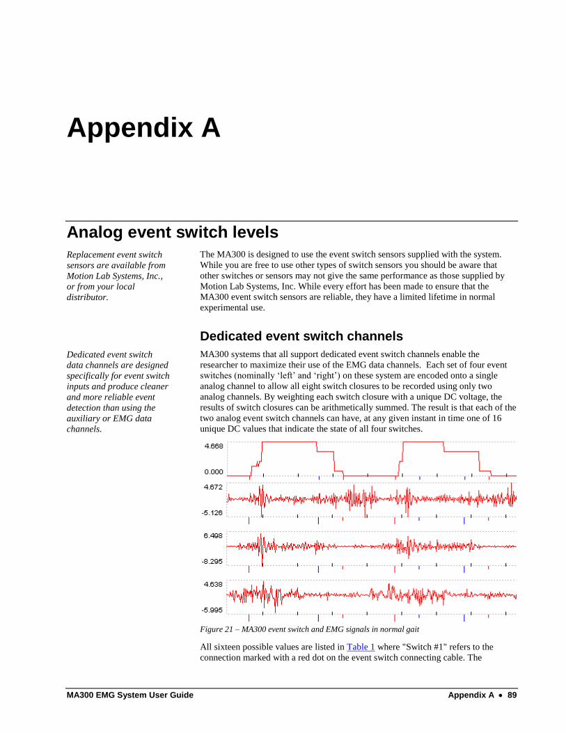
MA300 EMG System User Guide Appendix A 89
Appendix A
Analog event switch levels
Replacement event switch
sensors are available from
Motion Lab Systems, Inc.,
or from your local
distributor.
The MA300 is designed to use the event switch sensors supplied with the system.
While you are free to use other types of switch sensors you should be aware that
other switches or sensors may not give the same performance as those supplied by
Motion Lab Systems, Inc. While every effort has been made to ensure that the
MA300 event switch sensors are reliable, they have a limited lifetime in normal
experimental use.
Dedicated event switch channels
Dedicated event switch
data channels are designed
specifically for event switch
inputs and produce cleaner
and more reliable event
detection than using the
auxiliary or EMG data
channels.
MA300 systems that all support dedicated event switch channels enable the
researcher to maximize their use of the EMG data channels. Each set of four event
switches (nominally ‘left’ and ‘right’) on these system are encoded onto a single
analog channel to allow all eight switch closures to be recorded using only two
analog channels. By weighting each switch closure with a unique DC voltage, the
results of switch closures can be arithmetically summed. The result is that each of the
two analog event switch channels can have, at any given instant in time one of 16
unique DC values that indicate the state of all four switches.
Figure 21 – MA300 event switch and EMG signals in normal gait
All sixteen possible values are listed in Table 1 where "Switch #1" refers to the
connection marked with a red dot on the event switch connecting cable. The

90 Appendix A MA300 EMG System User Guide
maximum DC output level of each channel is set to be a maximum of 4.688 volts
when all four event switches are closed.
When combined with EMG recordings the resulting event switch signals are quite
easy to interpret, enabling the analyst to easily determine the gait cycle phases of
stance and swing.
While the discussion here is specific to clinical gait analysis, the event switch inputs
are not limited to recording event switches and can be used for any switch recording
needs, especially those that might require complete subject electrical isolation as the
event switch signals have the same electrical isolation specifications as the EMG
channels.
Default Analog Event Switch Output Voltages for the MA300
Switch #1 (Toe) Switch #2 (1st) Switch #3 (5th) Switch #4 (Heel) Output Volts
0.000 0.000 0.000 0.000 0.000
0.3125 0.000 0.000 0.000 0.313
0.000 0.625 0.000 0.000 0.625
0.3125 0.625 0.000 0.000 0.938
0.000 0.000 1.250 0.000 1.250
0.3125 0.000 1.250 0.000 1.563
0.000 0.625 1.250 0.000 1.875
0.3125 0.625 1.250 0.000 2.188
0.000 0.000 0.000 2.500 2.500
0.3125 0.000 0.000 2.500 2.813
0.000 0.625 0.000 2.500 3.125
0.3125 0.625 0.000 2.500 3.438
0.000 0.000 1.250 2.500 3.750
0.3125 0.000 1.250 2.500 4.063
0.000 0.625 1.250 2.500 4.375
0.3125 0.625 1.250 2.500 4.688
Table 1 - Analog event switch levels
Alternative MA300 event channels
MA300 systems that lack the dedicated event switch channels can store event switch
information by connecting an event switch with an adaptor cable to either an unused
EMG data channel or one of the auxiliary data channels available on many MA300
systems.
In each case, each event switch signals will be recorded on its own analog channel as
a positive pulse when the switch is closed. Thus two event switches on each foot
(heel and toe to detect the stance and swing phases of gait) will require four analog
channels.

MA300 EMG System User Guide Appendix B 91
Appendix B
Upgrading the MA300 The MA300 is a digital EMG system and has been designed to be completely self-
contained system with an absolute minimum of user adjustments and settings. The
only adjustment that is normally necessary is to set the low pass filter to match the
sampling rate of your data collection system. Individual EMG channel gains may be
adjusted for optimum recording levels.
Most MA300 systems can be upgraded to add additional channels by exchanging the
system backpack or returning the backpack to Motion Lab Systems for modification
and installation of additional EMG channels. Please contact Motion Lab Systems or
your distributor if you are interested in upgrading your system to add additional
EMG channels. All MA300 systems may be fitted with an optional band-pass filter.
Only technically qualified
personnel should attempt to
repair or customize an
MA300 EMG system.
If you are in any doubt as to your ability to repair or modify the MA300 EMG
system, or one of its options, then you should return the unit to Motion Lab Systems,
Inc, or their agents and request them to perform the required operations for you as
the MA300 is a patient connected device.
Service Contracts are available from Motion Lab Systems to provide full support of
your MA300 system. Please call us for current pricing and further information.
Upgrading to add additional EMG channels
The upgrade procedure is very simple. When you purchase the upgrade from Motion
Lab Systems you will receive a replacement subject backpack and additional EMG
preamplifier electrodes. Remove the EMG preamplifiers from the original subject
backpack and plug them into the upgrade backpack. Plug the additional EMG pre-
amplifiers that were supplied with the upgrade into the extra EMG channels. The
new, upgrade, subject backpack may now be plugged into the coaxial
interconnecting cable. The new upgraded backpack is now completely functional.
If the original installation anticipated that the system would be upgraded then you
may find that your system already has the additional EMG channels already
connected to your data acquisition system. If not you may need to connect and assign
additional analog channels to record or sample the new EMG channels that have
been added by the upgrade. Please contact Motion Lab Systems if you need a new
analog connection cable or advice on connection the additional channels to your
system. Once you are certain that the new system is completely functional you
should return the original subject backpack to Motion Lab systems or your agent to
complete the upgrade procedure.

92 Appendix B MA300 EMG System User Guide
Installing the MA300-F Band pass filter
You will need:
MA300-F filter installation kit.
A small amount of Loctite® or similar thread locking material.
Philips screwdriver, Open wrench and Hex Allen wrench
Instructions
1. The filter card mounts inside the MA300 Desk Top Unit (DTU). Turn the
DTU AC line power off and disconnect the AC line cord from the rear of
the DTU. Disconnect all other cables. These are the 25-way DB-25 analog
signal cable, LEMO coaxial cable and 9-way DB-9 connector (if used).
2. Move the DTU to a clean work area and find a small container to store
screws and other items that you remove from the unit as you open it - you
will need these when you re-assemble the DTU.
3. While facing the front of the DTU, gently lay the unit over to the left side.
All access to the inside of the DTU is from the right side of the unit.
4. Remove the two black plastic feet (on your right side) from the unit by
pulling them straight up to expose the recessed securing screws. Note that
the front and rear feet are slightly different - place the feet to one side - you
will need them to reassemble the unit.
5. Remove the two similar black plastic screw covers (on your left side) from
the top side of the cover by pulling them straight up to expose the recessed
securing screws. Place the two covers (front and rear) to one side - you will
need then to reassemble the unit.
6. Release all four securing screws using the Philips screwdriver and place
them to one side - you will need then to reassemble the unit.
7. Remove the plastic cover by lifting straight up to reveal the metal box that
contains the DTU electronics.
8. The internal metal cover is secured by fourteen (14) screws - remove all
fourteen screws, placing them carefully to one side - you will need then to
reassemble the unit. Each screw will have a small locking washer - try and
keep the washers with the screws as it will save you time later when you
replace the cover.
This completes the preparations
for installation.
9. Lift off the metal cover to reveal the internal electronics board and AC line
power supply in a separate shielded compartment. As you lift the cover
from the DTU - note that there is a small lip on the metal cover that mates
with the rear panel of the DTU.
10. Remove the large ribbon cable that runs from the base of the DTU and turns
at ninety degrees to a connector just above the AC power supply. The
MA300-F option card will replace this signal cable.
11. Remove the cover from the HP filter switch opening at the rear of the DTU
- this opening is directly above the LEMO interface connector.
12. Mount the rotary HP filter switch in the hole and route the switch wiring so
that it runs underneath the top lip of the metal DTU case, towards the front
of the DTU.

MA300 EMG System User Guide Appendix B 93
13. Secure the switch using the mounting hardware provided with the switch.
Rotate the switch such that the switch knob aligns with the printed filter
settings on the rear of the DTU.
14. Locate the two Phillips head mounting screws that are mid-line on the DTU
main electronics board. One is just below the ribbon cable that connects the
display card to the DTU main electronics card; the second screw is just
above and to the left of the AC power supply compartment. These screws
must be removed to allow the MA300-F option card to be secured to the
DTU main electronics card. Check their location using the mounting holes
on the MA300-F option card and remove both screws and locking washers.
These two screws and washers will not be needed again and can be
discarded.
15. Carefully insert the MA300-F option filter card into the two sets of
connectors on the DTU main electronics card. Note that the MA300-F
option connectors must align by pin numbers. Pin-1 on the filter card must
mate with Pin-1 on the DTU main electronics card. Due to the differing
number of pins on the two connectors this will result in the filter card
appearing to have one set of connecting sockets that do not mate with any
pins on the DTU main electronics card. This is correct.
16. When the filter card is inserted correctly, place the two spacers (supplied) in
between the MA300-F option card and the DTU main electronics board so
that they align with the two mounting holes in the two printed circuit cards.
Use a small amount of Loctite® on each of the two screws (supplied) and
attach the MA300-F option card to the DTU main electronics card using the
spacers provided.
Figure 22 - Band Pass filter showing preset LP switch and HP switch connector.
17. Connect the filter switch cable to the MA300-F option card. The 8-way
connector is at the top of the MA300-F option card and the wires from the
switch will dress into the connector from below if the connector is aligned
correctly.
This completes the functional
installation of the MA300-F
option card.
18. Check that the DIP switch settings for the LP filter are set to the correct
values. You may wish to change the default LP filter setting depending on
your EMG data collection environment.
19. Replace the metal cover that you removed in step 9, taking care to make
sure that the lip is fitted against the rear cover and that the screw holes all
line up.
20. Secure the metal cover to the main DTU box using the fourteen screws and
locking washers that were removed in step 8.
21. Replace the plastic cover and secure using the four Philips head screws that
were removed in step 6.

94 Appendix B MA300 EMG System User Guide
22. Replace the two black plastic feet, taking care to make sure that the front
and rear feet are pushed into the correct holes, as the two feet are not
interchangeable. Replace both of the top screw covers making sure that the
front and back covers fit into the right holes.
The upgraded MA300 is now
ready to use.
23. Reconnect the DTU to the AC power and test the system by applying EMG
signals to each EMG channel in turn and confirming that the EMG signal
appears on the recording or measuring device.
Filter Switch Settings
The optional MA300-F band-pass filter implements a sophisticated pair of separate
low-pass and high-pass filters on each EMG channel. The low-pass filter settings are
preset when the system is installed and cannot be easily changed by the user. This
feature enables the MA300 to be configured (if desired) so that it always limits the
high frequency component of the EMG signal to a value that can be handled by any
external recording or measurement system. Each filter is implemented using a
combination of analog and digital filters - all EMG channels are filtered at the same
frequency.
The high-pass filter is user adjustable via a rotary switch at the rear of the MA300
desktop unit and supports the following filter points:
MA300-F High Pass Filter
25 Hz.
40 Hz.
60 Hz.
80 Hz.
100 Hz.
120 Hz.
The low-pass filter that is built into the MA300-F should be set to a value that
depends on the maximum sampling or measuring rate that you will be using with
your analog recording or measuring system. The MA300-F low-pass filter allows
you to limit the high-end bandwidth of the MA300 system regardless of the setting
of the subject backpack filter switch. This is especially useful in situations where the
MA300 is used with a fixed clinical protocol that requires specific analog data
sampling rates or where the installation engineer wishes to make sure that the EMG
system cannot generate ‘out-of-band’ signals regardless of the users LP filter
selection in the backpack.
The default filter frequency for the MA300-F low-pass filter is -3 dB at 2,000 Hz as
shown below. Many common gait labs will select a lower frequency such as 600Hz
if they are sampling data at 1,200 samples per second (i.e. 20 samples per 60Hz
video frame). Switches shown as “1” are ON. The MA300-F filter setting will then
override any higher value selected using the backpack switch.
MA300-F Low Pass Filter Settings
Filter Selection Minimum Sample Rate DIP switch
2,000 Hz. Default 4,000 s/sec. 0-1-1-0-1-1-1-1
1,800 Hz. 3,600 s/sec. 1-0-1-0-1-1-1-1

MA300 EMG System User Guide Appendix B 95
1,500 Hz. 3,000 s/sec. 1-1-0-0-1-1-1-1
1,400 Hz. 2,800 s/sec. 0-1-0-0-1-1-1-1
1,300 Hz. 2,600 s/sec. 1-0-0-0-1-1-1-1
1,250 Hz. 2,500 s/sec 0-0-0-0-1-1-1-1
1,200 Hz. 2,400 s/sec. 1-1-1-1-0-1-1-1
1,100 Hz. 2,200 s/sec. 0-1-1-1-0-1-1-1
1,050 Hz. 2,100 s/sec. 1-0-1-1-0-1-1-1
1,000 Hz. 2,000 s/sec. 0-0-1-1-0-1-1-1
950 Hz. 1,900 s/sec. 1-1-0-1-0-1-1-1
900 Hz. 1,800 s/sec 0-1-0-1-0-1-1-1
850 Hz. 1,700 s/sec 0-0-0-1-0-1-1-1
800 Hz. 1,600 s/sec. 1-1-1-0-0-1-1-1
750 Hz. 1,500 s/sec. 1-0-1-0-0-1-1-1
700 Hz. 1,400 s/sec. 1-1-0-0-0-1-1-1
650 Hz. 1,300 s/sec. 1-0-0-0-0-1-1-1
600 Hz. 1,200 s/sec. 1-1-1-1-1-0-1-1
550 Hz. 1,100 s/sec. 0-0-1-1-1-0-1-1
500 Hz. 1,000 s/sec. 0-0-0-1-1-0-1-1
450 Hz. 900 s/sec. 0-0-1-0-1-0-1-1
400 Hz. 800 s/sec. 0-1-1-1-0-0-1-1
350 Hz. 700 s/sec. 1-1-1-0-0-0-1-1
300 Hz. 600 s/sec. 0-1-1-1-1-1-0-1
250 Hz. 500 s/sec 0-0-0-0-1-1-0-1
200 Hz. 400 s/sec 1-0-1-1-1-0-0-1
175 Hz. 350 s/sec 1-0-1-1-0-0-0-1
150 Hz. 300 s/sec 1-1-0-1-1-1-1-0
125 Hz. 250 s/sec 0-0-0-0-1-0-1-0
100 Hz. 200 s/sec 0-0-0-1-1-1-0-0


MA300 EMG System User Guide Appendix C 97
Appendix C
Installation
The MA300 AC power
supply will automatically
select the correct AC line
voltage – no adjustment is
required.
The MA300 uses a modern switching power supply that meets all international
safety standards for medical equipment. It is also a “smart” power supply and will
automatically set itself to the correct line voltage within any of the common ranges
(100 to 240 Volts AC 50/60Hz) when the system is turned on. There is no need to
open or adjust the MA300 to select an AC line voltage.
Each MA300 system is fully tested before shipment to the customer and end-user
and, while we cannot guarantee that nothing will go wrong, we have found that
virtually all initial problems with a new system are caused by faulty connections or
miss-wiring the interface to the users analog data collection system. You can
improve the chances of an easy installation by reading this appendix and carefully
testing the system configuration before serious use of the MA300 with subjects.
The MA300 consists of two units (back-pack and desk-top unit) that are connected
together by a lightweight RG-174/U coaxial cable. The standard system is designed
to be completely self-contained and is very easy to setup and configure for use in any
Gait, Biomechanics, or Motion Analysis Laboratory. It provides electrically isolated,
real time analog signals from EMG pre-amplifiers placed on a subject’s skin surface,
as well as other signals from optional event switches and other data channels.
In most
circumstances
MA300 system
installation consists
of connecting the
supplied analog
interface cable to an
Analog Data
Capture (ADC) or
Data Recording
system. This cable
has a female 25-pin
connector on one
end and 26 free-
floating leads on the
other end - details of
the connector pin-
out are provided in
this manual. Each of the free-floating leads is labeled with an appropriate label
indicating its function. This would be a good point to stop and find the analog

98 Appendix C MA300 EMG System User Guide
interface cable and examine it - you should find it packaged with a sheet of paper
that provides some details of the pin to cable connections. An analog connection
cable with individual BNC connectors is available on request.
The MA300 also features a female 9-pin connector on the rear panel marked
“Option” (or “Display on some models). This connector supplies access to digital
signals - it does not contain any analog signals and should not be connected directly
to any analog data collection system.
The system installer should read the documentation that is provided with the data
collection system that is to be used with the MA300 before starting the installation.
Since the MA300 can be used with almost any data collection system it is difficult to
provide precise and specific instructions on every installation situation. However the
following issues are common to almost every situation:
MA300 Outputs
All MA300 outputs are static protected and voltage limited internally to no more
than ± 5 volts. Each output is single-ended, using a common signal return point, and
is driven by a current limited, low impedance source.
Signal Channels
The MA300 system can support different numbers of signal channels that may
contain specific data. It is not always possible to translate MA300 channel
numbering to use identical data collection channel numbers. Make sure that the
system user knows what MA300 channels are connected and which channels the data
collection system uses to record or display EMG, Event Switch and Research Data.
Note that the standard analog signal cable is supplied with connections for all sixteen
analog channels even when the system has fewer EMG channels. If at all possible it
is recommended that all sixteen channels are connected when the system is first
installed as this will make any subsequent upgrades much easier if the user decides
to upgrade the system at any time.
Ground
Also known as “Signal Return” - it is vital that the MA300 Ground is connected to
the Analog ground (or signal return) of the users data collection system. Failure to
connect the MA300 Signal Return will result in crosstalk and noisy signals. Most
initial data quality problems are caused by poor (or non-existent) ground
connections.
Data Parity
This is a TTL level signal that indicates any problems with the digital data
transmission. In most circumstances it can be ignored or connected to an unused
analog channel. If connected to an analog channel it will have a level of between
4.75 to 4.95V when EMG and other signals are being transmitted without any errors.
Do not connect this signal to any analog ground.
MA300 Case
This is connected to the MA300 case. It is an electrical ground for the metal case and
should be connected to the chassis or safety ground of the data collection system. In
many cases this can be connected to the analog signal ground. If problems are occur
with AC interference or excessive noise in the EMG signal then this connection can
be moved to the Signal Return Ground (above), the AC line ground, the chassis
ground of your data recording system or disconnected.

MA300 EMG System User Guide Appendix C 99
Shield
This is a connection to the shield of the signal cable supplied with your MA300
system. It should be connected to the data collection system analog signal ground. Its
function is to provide electrical shielding for the analog data signals in the MA300
cable. This lead does not make any electrical connection to the MA300. It is not a
substitute for the Ground connection.
Configuration
If you are not familiar with the data measurement, or data collection system, that you
are using then this is a good place to stop and read the manuals that were supplied
with the data collection or recording system that you are planning to use.
Once the MA300 analog cable has been connected to the your data collection system
it is a good idea to start up the data collection system and setup the data collection
parameters before applying power to the MA300. In general there are two parameters
that you will need to check - these are input signal level and sample rate.
Signal Level
All analog signals generated by the MA300 are in the range of ± 5 volts so you need
to set the analog data collection system to record data or accept input signals at this
level. If you select a lower level (i.e. ± 2.5 volts) then the MA300 signals may be
clipped or distorted and will not be measured correctly. If you select too high a level
(i.e. ± 10 volts) then the measured signals will be too small and you will loose some
resolution or precision.
Sample Rate
The simple rule of thumb for setting the analog data collection sample rate is to
always sample the data at twice the rate of the highest frequency present in the
signal. Since the maximum bandwidth for MA300 systems with a variable low pass
filter is DC to 2,000 Hz this would require a very high sample rate (a minimum of
4,000 and preferably at least 5,000 analog samples per second per channel) unless
the signal is filtered to remove the higher frequency components. This is normally
done by setting the anti alias, low pass filter on these systems to a suitable value.
Most of the signal power from surface EMG is lower than 350 Hz so setting the
backpack filter to 350 Hz reduces the analog data recording requirements
considerably if all of the EMG data is limited to surface recordings. The system user
will usually know what signal bandwidth is required.
It is a good idea to allow for some degree of over-sampling when you set the analog
sample rate so if you were setting the backpack LP filter to 350Hz then a sample rate
of between 700 and 1000 samples per second per channel would be appropriate.
Some MA300 systems have a fixed DC to 1000Hz bandwidth – these systems must
be sampled at a rate of 2000 samples per second per channel or faster.
Testing
Once the MA300 system is connected you will need to make some test recordings or
measurements to confirm that the system is (a) operational and, (b) working correctly
with your analog measurement system. So connect the system to the AC line using
the power cable supplied and turn on the power:
a) If the MA300 is operational then you should see a green Power Status light
turn on. If the backpack is not connected to the desktop unit (or is not

100 Appendix C MA300 EMG System User Guide
functioning correctly) then you will also see the amber No Signal (No.Sig)
and CRC lights turn on. If the backpack is connected and functioning
correctly then both of these lights will be off - disconnect the backpack and
you will see them both turn on. When the backpack is connected you should
also see a green light on the backpack indicating that power is reaching the
backpack. This sequence of operations checks that all major systems within
the MA300 are functional.
b) Check that the system is working correctly by connecting a single EMG
electrode to channel one and using it to make a test recording. Check that
the EMG signal is recorded on the correct channel and not any other
channels of the analog data measurement system. Check all the EMG
channels in this way to verify the MA300 EMG channels are connected to
the correct analog channels on the users system. If you find any errors then
correct them and restart the test from channel one.
If you are using event switch channels then connect the event switches to the
backpack and check their operation using the green front panel lights that indicate
event switch closure. Check that the correct DC levels are recorded by the users
analog data collection system and that they are recorded on the correct channels -
make sure that the left and right sides are connected and labeled correctly as getting
these swapped can confuse any subsequent data analysis.
When connected correctly the MA300 should provide many years of trouble-free
service. Please contact Motion Lab Systems if you have any questions about either
the installation information provided or the operation of the MA300 system.
Changing the Fuses
1. Insert a pocket screwdriver at point “X” as shown. Gently lift UP until the entire
door lifts up approximately 1/4" (minimum).
2. Once lifted, the door will pivot on its hinges and expose the fuse holder.
3. When the fuse holder is installed in the single fuse position, apply the screwdriver
as shown and gently pry up. Use screwdriver as shown, do not use fingers.

MA300 EMG System User Guide Appendix C 101
When the fuse holder is installed in the dual fuse position, it will normally release as
soon as the door is opened.
Fusing Options
The MA300 supports both US and European fuses – it is supplied configured for
European fuses.


Index 103
Index
AC power requirements
Fuses ........................................................................ 17
Safety ....................................................................... 20
AC Power requirements
Voltage selection ..................................................... 20
Coaxial cable
Length ...................................................................... 46
Configuration
Default settings ........................................................ 24
EMG output ............................................................. 24
Foot switch signals .................................................. 32
Fault Detection
Indicator Lights ........................................................ 36
Typical symptoms .................................................... 36
Filters
Control connector .................................................... 82
Default settings ........................................................ 24
High pass filter selection.......................................... 87
Low pass filter selection .......................................... 86
Ranges available ...................................................... 30
Foot switches
Default output levels ................................................ 24
Description ............................................................... 45
Front panel indicators .............................................. 36
Output connections .................................................. 81
Output signals available ........................................... 32
Sensors ..................................................................... 33
Testing operation ..................................................... 33
Maintenance
Internal Adjustments ................................................ 20
Preamplifier electrodes
Abrading the skin surface ........................................ 51
Cleaning ................................................................... 51
Fine Wire applications ............................................. 42
Placement ................................................................. 51
Usage ....................................................................... 41
Safety
Power Supply ........................................................... 17
Setup
Connections ............................................................. 81
Raw vs Envelope ..................................................... 24
Safety ....................................................................... 20
Using the system ...................................................... 39
Specifications
EMG Characteristics ................................................ 15
Physical Characteristics............................................ 18
Subject preparation
Cleaning the skin ...................................................... 51
Electrode placement ................................................. 51
Running the test........................................................ 52
Subject Preparation
Foot switches ............................................................ 49
Planning ................................................................... 48
Related Documents