M5.1, 5.2 Report on measurements for the visual characterization of facade systems WP5. Measurements, T5.1 Authors. Hauer M., Geisler-Moroder D. (BB) Date: 12/2019

Welcome message from author
This document is posted to help you gain knowledge. Please leave a comment to let me know what you think about it! Share it to your friends and learn new things together.
Transcript
M5.1, 5.2 Report on measurements for the visual characterization of facade systems
WP5. Measurements, T5.1 Authors. Hauer M., Geisler-Moroder D. (BB)
Date: 12/2019
FACEcamp, M5.1, 5.2 Report on measurements for the visual characterization of facade systems 2/19
Table of Contents
1 Introduction 4
2 Objectives 4
3 Methodology 4
4 Results 4
5 Conclusions 5
Technical Annex 6
1 Visual characterization of facade systems with BSDFs – Basics 6
1.1 Definition 6
1.2 The rendering equation 7
1.3 Physical plausibility 8
2 BSDF formats 8
2.1 Klems patches 8
2.2 Tregenza patches 9
2.3 Variable resolution BSDFs 10
2.4 BSDF data and file formats 10
3 Generating BSDFs by simulations 11
3.1 Simulation 11
3.2 RADIANCE – genBSDF 11
3.3 LBNL WINDOW7 11
4 BSDF standardization 11
4.1 Ongoing work 11
5 Generating BSDFs by measurements 12
5.1 Overview on measurement approaches 12

FACEcamp, M5.1, 5.2 Report on measurements for the visual characterization of facade systems 3/19
5.2 Comparison of the different measurement approaches 13
6 Current BSDF measurement possibilities at Bartenbach 15
6.1 Used methods for visual characterization 15
6.2 New measurement device: Mini-Diff V2 16
7 References 18
FACEcamp partners 19

FACEcamp, M5.1, 5.2 Report on measurements for the visual characterization of facade systems 4/19
1 Introduction Within the FACEcamp task 5.1, the existing measurement methods for visual characterization of shading and daylight systems have been analysed as well as new concepts investigated via testing setups. The outcomes enrich the knowledge basis for further investigations and to derive measurement methods towards a standardized characterization scheme for complex façade systems.
2 Objectives This report aims at describing the physical fundamentals as well as the established methods for the visual measurement characterization of complex façade systems through determination of Bidirectional Scattering Distribution Function (BSDF) datasets.
3 Methodology The following steps were addressed within this report towards a visual system characterisation and described in detail:
• Definition and characteristic of a BSDF
• Provided resolutions and data formats
• Generation of BSDFs via simulation and measurement methods
• New design approaches for a BSDF measuring system: Instrumental Investigations and current possibilities at Bartenbach
4 Results The work, presented in detail in the technical annex, has achieved the mapping of existing methods for the determination of the BSDF as well as the scouting of possible new approaches. With BSDFs (Bidirectional Scattering Distribution Functions) it is possible to efficiently represent diffuse shading blinds as well as specular redirecting components with their transmitting and reflecting characteristics of visible and solar radiation (see Technical Annex chapter 1). Although the Klems-resolution based BSDF has been established as a standard for daylight simulations as well as energy calculations of complex facades, for specific tasks like glare detection, higher resolution BSDFs are highly recommended and a highly relevant topic in research at the moment (see Technical Annex chapter 2). Most sophisticated software tools in this field (e.g. Radiance, EnergyPlus, TRNSYS…) have implemented those models. International Databases (e.g. LBNL’s Complex Glazing Database) or Tools (e.g. LBNL’s WINDOW7, Radiance’ genBSDF) enable meanwhile to freely create such BSDF data based on a geometrical model (see Technical Annex chapter 3). Due to the different standards and resolution, a harmonization work has been started within IEA SHC Task 61, while FACEcamp focused on screening workflows on suitable daylighting- and energy simulation software especially applicable for complex façade systems and towards standardizing model input formats (see Technical Annex chapter 3). Worldwide, different methods have been established to elaborate BSDFs directly from measurements. While BSDF-generation via simulation allows higher flexibility, less time and costs, several approximations or idealisations are made in the modelling process, which might lead to significant differences compared to reality. Measurement might close these gaps, that’s why a

FACEcamp, M5.1, 5.2 Report on measurements for the visual characterization of facade systems 5/19
combination of measurement and simulation can optimize this process (see Technical Annex chapter 5). Therefore, Bartenbach has established a combined simulation and measurement method, which allows to use the flexibility and efficiency of simulations, while incorporating methods for reliability-checks of the gained results using the Mini-Diff V5 (see Technical Annex chapter 6).
5 Conclusions The screening and evaluation of methods in FACEcamp WP5 to characterize complex façade systems from different aspects (daylighting, glare, energy demand) have shown the BSDF as a highly valuable method to provide the necessary data. Nevertheless, in the branches of the façade, shading and cladding industry, BSDFs are still known by a minority. Furthermore, the methods to derive reliable BSDF data requires significant details in material and geometry description. Furthermore, planners are mostly not aware about those capabilities or do not have the expertise and tools to deal with those aspects in detail. The Technical Annex of this report might give advice in this direction by address all those aspects. It gives a summarized overview on the state of research as well as existing standards and methods to characterize complex façade systems with higher reliability and efficiency.

FACEcamp, M5.1, 5.2 Report on measurements for the visual characterization of facade systems 6/19
Technical Annex
1 Visual characterization of facade systems with BSDFs – Basics
1.1 Definition Even though, standardized methods for characterizing angle-dependent solar-optical properties of transparent glazing surfaces based on their physical principles (i.e. visible and solar transmittance, reflectance and absorptance, solar heat gain coefficient) are well established, for optically complex structures (like light scattering or daylight redirecting systems) only methodical concepts exists, which are not standardized. The BSDF is a fundamental radiometric concept, and accordingly the BSDF has established itself as a physically measurable quantity in different applications. In optics it is used for the characterization of surfaces or model development for optical simulation, in computer graphics for realistic modelling of materials and surface properties. Surface technology uses BSDF for the characterization of surface qualities, and increasingly BSDF find a way into the building industry, for the description and modelling of highly complex facades in building energy simulation as well as daylight simulations. Depending on the system to be described (Clear glass/films, venetian blinds, fabrics…) and the investigated ratings (interior illuminance evaluation, glare evaluation, luminance, energy balancing…), different requirements on the BSDF dataset in terms of resolution (Klems/ Tregenza/ Shirley-Chiu) are given.
Figure 1: BSDF requirements.
The bidirectional scattering distribution function (BSDF) is the general mathematical function which describes the scattering of optical radiation from a surface as a function of the angular positions of the incident and scattered beams. It is the ratio of radiance on the exiting side to incident irradiance. In practice the term bidirectional reflection distribution function (BRDF) is used when it is specifically about reflected scattering. Likewise, the bidirectional transmission distribution function (BTDF) refers to scattering transmitted through a material.

FACEcamp, M5.1, 5.2 Report on measurements for the visual characterization of facade systems 7/19
Figure 2: The composition of a BSDF. BSDF = (BTDF + BRDF), BSDF – bidirectional scattering distribution
function, BRDF – bidirectional reflection distribution function, BTDF – bidirectional transmission distribution function. (Source: https://en.wikipedia.org/wiki/Bidirectional_scattering_distribution_function)
Using BSDFs, it is possible to efficiently integrate shading and daylighting systems in building energy simulations of thermal performance (i.e., solar heat gains through a window with a shade attachment) even without detailed information of the system’s geometric or material properties. However, the Klems subdivision of the hemisphere where every patch corresponds to an average solid angle of 0.043 sr (which corresponds to a cone with a 2x6.7° apex angle) must be handled with care when used to compute other performance parameters that require accurate spatial distribution of illuminance / irradiance or luminance / radiance in the indoor space (such as annual sunlight exposure (ASE), discomfort glare, thermal comfort). Therefore, beside the initial Klems resolution, different resolutions for BSDF datasets have been established in recent years, which will be introduced in the following chapter.
1.2 The rendering equation

FACEcamp, M5.1, 5.2 Report on measurements for the visual characterization of facade systems 8/19
(θ l,φ l) light source direction
(θv,φv) viewpoint direction
f(θ l,φ l; θv,φv) BRDF
Ll (θ l,φ l) radiance from the light source direction
Lv (θv,φv) radiance to viewpoint direction
(Kajiya J. T. 1986; Nicodemus et al. 1977)
1.3 Physical plausibility Positivity
f(θl,φl ;θv,φv) ≥ 0
Helmholtz reciprocity:
f(θl,φl ;θv,φv) = f(θv,φv ;θl,φl)
Energy balance:
Albedo
bounded by 1 BSDFs need to have additional properties, including positivity, obeying Helmholtz reciprocity and conserving energy. In this way they can represent physically plausible materials in the rendering equation (Kajiya J. T. 1986; Nicodemus et al. 1977).
2 BSDF formats
2.1 Klems patches In 1994, Klems proposed that the solar heat gain coefficient (SHGC) of optically complex fenestration systems be calculated based on a 145x145 discretization of incident and exiting hemispheres. This hemispherical basis subdivision scheme, which yields approximately equal irradiances for each patch at constant radiance, is used in simulation tools such WINDOW7 or RADIANCE to describe a
Figure 3: : Diagram showing vectors used to define the BSDF
FACEcamp, M5.1, 5.2 Report on measurements for the visual characterization of facade systems 9/19
system's bidirectional scattering distribution function (BSDF i.e., the angle-dependent, solar-optical properties of the system). Key facts of the Klems scheme:
• subdivision of hemisphere into 145 patches
• approx. equal illuminance from each patch if luminance is constant in hemisphere
• 9 θ ranges {0°-5°, 5°-15°, 15°-25°, 25°-35°, 35°-45°, 45°-55°, 55°-65°, 65°-75°, 75°-90°}
• Φ subdivisions per θ range {1, 8, 16, 20, 24, 24, 24, 16, 12}
• average solid angle 2π/145 = 0.0433 sr, i.e. cone with 2 x 6.73° apex angle [2π*(1-cos(α/2)) = 2π/145]
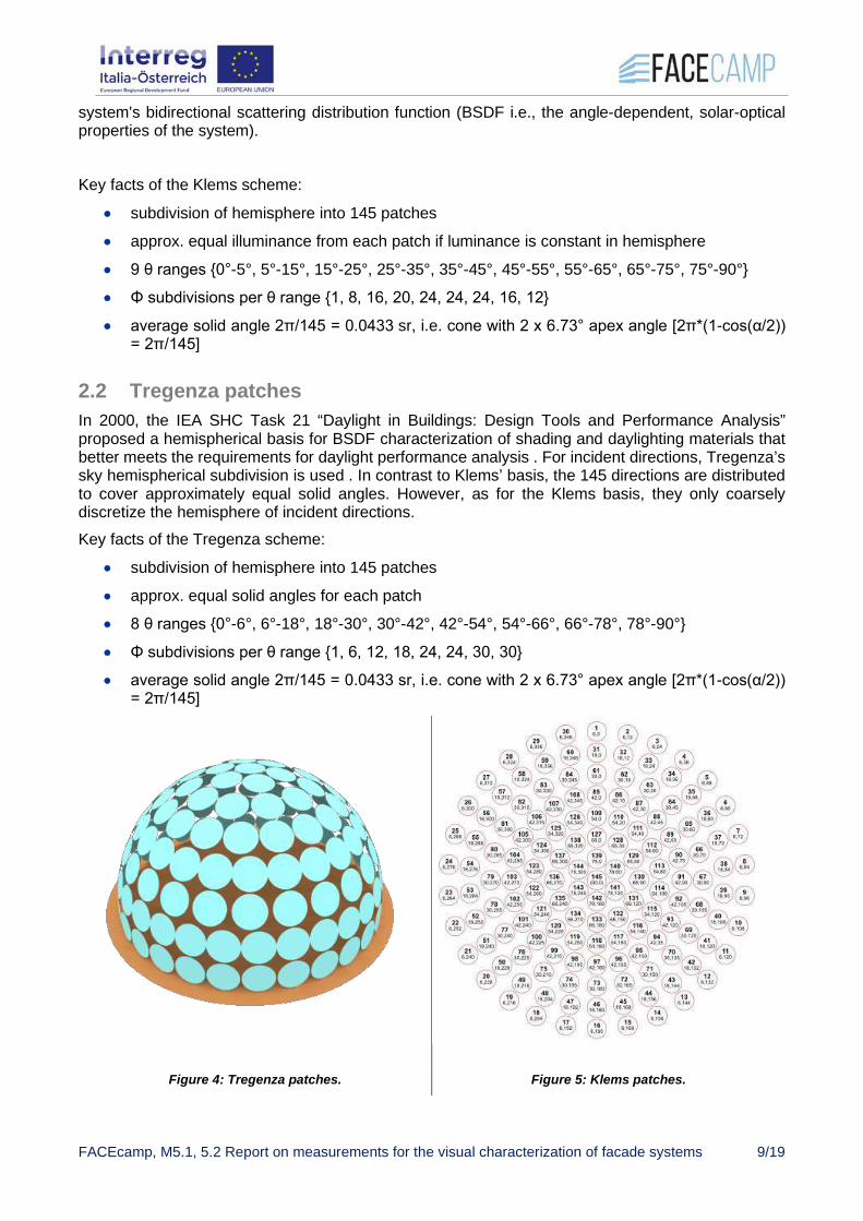
2.2 Tregenza patches In 2000, the IEA SHC Task 21 “Daylight in Buildings: Design Tools and Performance Analysis” proposed a hemispherical basis for BSDF characterization of shading and daylighting materials that better meets the requirements for daylight performance analysis . For incident directions, Tregenza’s sky hemispherical subdivision is used . In contrast to Klems’ basis, the 145 directions are distributed to cover approximately equal solid angles. However, as for the Klems basis, they only coarsely discretize the hemisphere of incident directions. Key facts of the Tregenza scheme:
• subdivision of hemisphere into 145 patches
• approx. equal solid angles for each patch
• 8 θ ranges {0°-6°, 6°-18°, 18°-30°, 30°-42°, 42°-54°, 54°-66°, 66°-78°, 78°-90°}
• Φ subdivisions per θ range {1, 6, 12, 18, 24, 24, 30, 30}
• average solid angle 2π/145 = 0.0433 sr, i.e. cone with 2 x 6.73° apex angle [2π*(1-cos(α/2)) = 2π/145]
Figure 4: Tregenza patches. Figure 5: Klems patches.

FACEcamp, M5.1, 5.2 Report on measurements for the visual characterization of facade systems 10/19
2.3 Variable resolution BSDFs For specular and scattering systems, the coarse representations Klems and Tregenza may lead to significant errors. To overcome this, a variable resolution BSDF approach was introduced by Ward et al. , that enables high accuracy via fine angular resolution for steep gradients of the BSDF while providing a coarse structure in areas with flat gradients.
• high resolution for spikey regions
• low resolution for smooth regions
• based on Shirley-Chiu-mapping (preserves fractional area, i.e. projected solid angle)
• maximum dimensions in 4D 22n x 22n (n = 4 / 5 / 6: 2562 / 10242 / 40962) This enables a highly efficient data structure (ideal diffuse reflector needs a single value {1/π}). On the other side, the BSDF data leaves the fixed matrix structure, which brings restrictions in flexibility using the established “phase-methods” for efficient daylight simulations of CFS. Either the daylight coefficient approach (DC) is used or the extended 5-phase method, which uses variable resolution BSDFs for high resolution required calculations (e.g. glare evaluation).
2.4 BSDF data and file formats Table 1: Established data formats:
Name Input resolution Output resolution Currently used by software
WINDOW7 Klems (145) Klems (145) WINDOW7, Relux, Radiance
IEA 21 Tregenza (145) 5deg full, i.e. 5°x5° (1297)
Relux, Dialux, Radiance
Shirley-Chiu variable (limitation through data size)
variable (limitation through data size)
Radiance
Figure 6: XML file format. Definition of data discretization in header → data blocks interpreted by software accordingly
FACEcamp, M5.1, 5.2 Report on measurements for the visual characterization of facade systems 11/19
3 Generating BSDFs by simulations
3.1 Simulation • genBSDF: part of the RADIANCE software package
http://radiance-online.org/cgi-bin/viewcvs.cgi/ray/src/util/genBSDF.pl
• WINDOW7: LBNL software for calculation of total window thermal performance indices
http://windows.lbl.gov/software/window/window.html
• commercial software (e.g. LucidShape, ASAP, LightTools, TracePro, …): calculation of illumination and conversion from ray file to patches
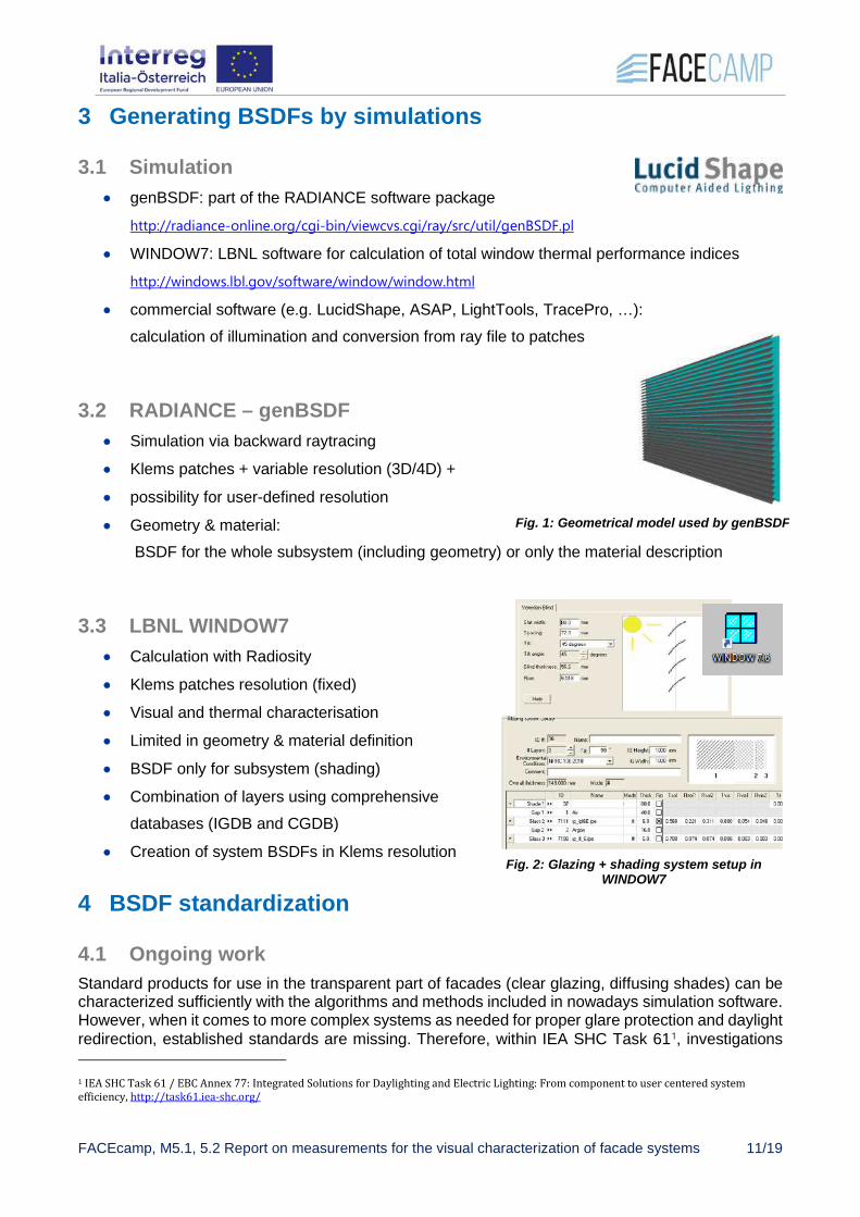
3.2 RADIANCE – genBSDF • Simulation via backward raytracing
• Klems patches + variable resolution (3D/4D) +
• possibility for user-defined resolution
• Geometry & material: BSDF for the whole subsystem (including geometry) or only the material description
3.3 LBNL WINDOW7 • Calculation with Radiosity
• Klems patches resolution (fixed)
• Visual and thermal characterisation
• Limited in geometry & material definition
• BSDF only for subsystem (shading)
• Combination of layers using comprehensive databases (IGDB and CGDB)
• Creation of system BSDFs in Klems resolution
4 BSDF standardization
4.1 Ongoing work Standard products for use in the transparent part of facades (clear glazing, diffusing shades) can be characterized sufficiently with the algorithms and methods included in nowadays simulation software. However, when it comes to more complex systems as needed for proper glare protection and daylight redirection, established standards are missing. Therefore, within IEA SHC Task 611, investigations
1 IEA SHC Task 61 / EBC Annex 77: Integrated Solutions for Daylighting and Electric Lighting: From component to user centered system efficiency, http://task61.iea-shc.org/
Fig. 1: Geometrical model used by genBSDF
Fig. 2: Glazing + shading system setup in WINDOW7

FACEcamp, M5.1, 5.2 Report on measurements for the visual characterization of facade systems 12/19
on procedures of BSDFs are made towards a standardized representation of complex facade systems. Research activities within FACEcamp focused on screening workflows on suitable daylighting- and energy simulation software especially applicable for complex façade systems (FACEcamp toolchain). Also, in FACEcamp different BSDF measurement methods have been investigated and were contributed to the international Task 61 activities.
5 Generating BSDFs by measurements
5.1 Overview on measurement approaches There are different approaches to the practical measurement of BSDFs. A BSDF measurement setup usually consists of a light source, a sample mount and a detector. In a simple setup, all components are mounted “in plane” on an optical table, resulting in data along the scattering plane only. However, for the majority of samples, this is not sufficient. Out-of-plane setups come in two varieties: Scanning goniophotometers move a detector mechanically around the sample, while imaging goniophotometers capture images of the resulting luminance distribution on a receiver surface and calculate the BSDF from this.
In-plane measurements Scanning goniophotometer CCD based goniophotomter
Image: www.pab-opto.de
Image: J. Kämpf, 2011
Source: www.lighttec.fr
Source: www.lighttec.fr
Fig. 3: Methods of BSDF determination by measurements
FACEcamp, M5.1, 5.2 Report on measurements for the visual characterization of facade systems 13/19
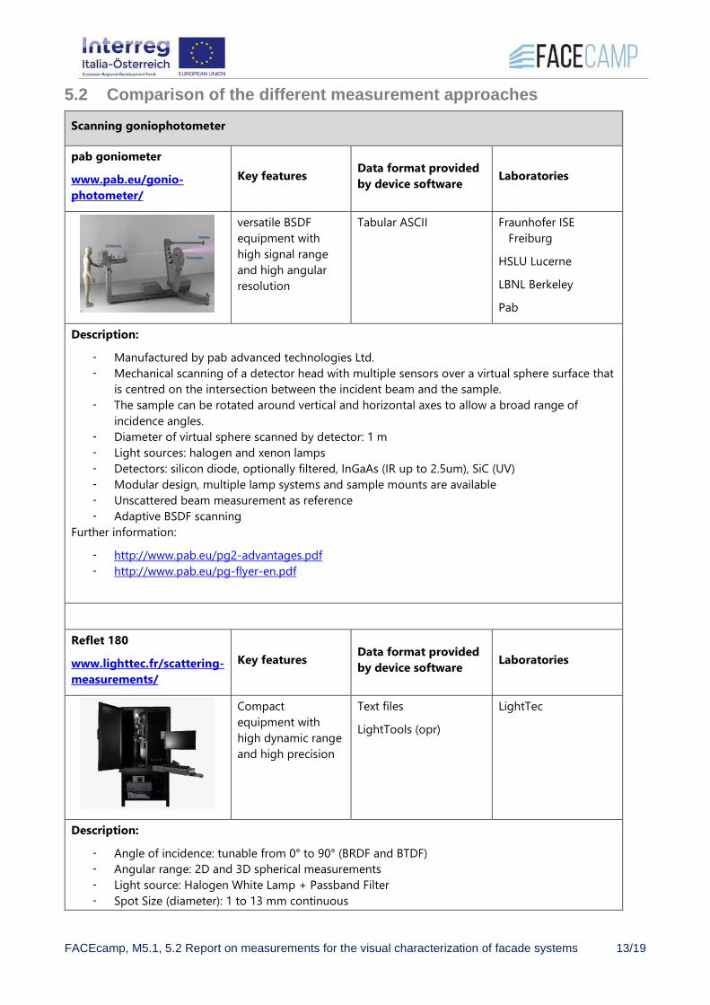
5.2 Comparison of the different measurement approaches Scanning goniophotometer
pab goniometer
www.pab.eu/gonio-photometer/
Key features Data format provided by device software Laboratories
versatile BSDF equipment with high signal range and high angular resolution
Tabular ASCII Fraunhofer ISE Freiburg
HSLU Lucerne
LBNL Berkeley
Pab
Description:
- Manufactured by pab advanced technologies Ltd. - Mechanical scanning of a detector head with multiple sensors over a virtual sphere surface that
is centred on the intersection between the incident beam and the sample. - The sample can be rotated around vertical and horizontal axes to allow a broad range of
incidence angles. - Diameter of virtual sphere scanned by detector: 1 m - Light sources: halogen and xenon lamps - Detectors: silicon diode, optionally filtered, InGaAs (IR up to 2.5um), SiC (UV) - Modular design, multiple lamp systems and sample mounts are available - Unscattered beam measurement as reference - Adaptive BSDF scanning
Further information:
- http://www.pab.eu/pg2-advantages.pdf - http://www.pab.eu/pg-flyer-en.pdf
Reflet 180
www.lighttec.fr/scattering-measurements/
Key features Data format provided by device software Laboratories
Compact equipment with high dynamic range and high precision
Text files
LightTools (opr)
LightTec
Description:
- Angle of incidence: tunable from 0° to 90° (BRDF and BTDF) - Angular range: 2D and 3D spherical measurements - Light source: Halogen White Lamp + Passband Filter - Spot Size (diameter): 1 to 13 mm continuous

FACEcamp, M5.1, 5.2 Report on measurements for the visual characterization of facade systems 14/19
- Wavelength detector sensitivity: 400 to 1700 nm - Detector Acceptance Angle: +/-0,04°/ 1,1°/ 2° - Minimum BRDF: 10e-4 - Dynamic range: 10e9 for visible and 10e6 for IR range
Image based goniophotometer
IBP / EPFL
www.ibp.fraunhofer.de
www.epfl.ch
Key features Data format provided by device software Laboratories
Comprehensive BTDF monitoring
IEA 21, Text files EPFL Lausanne
Fraunhofer IBP Stuttgart
Description:
- Angle of incidence from 0° to 90° - Light source: Hydrargyrum Medium-arc Iodide lamp (5600 K colour temperature) - Spot size (diameter): 6 to 15 cm - Wavelength detector sensitivity: visual range, fitted with the photopic luminosity function - Minimum BTDF: 10e-3 - Maximum resolution in exiting hemisphere: 1297 (5°) - Duration: 12 hrs for 145 incident directions
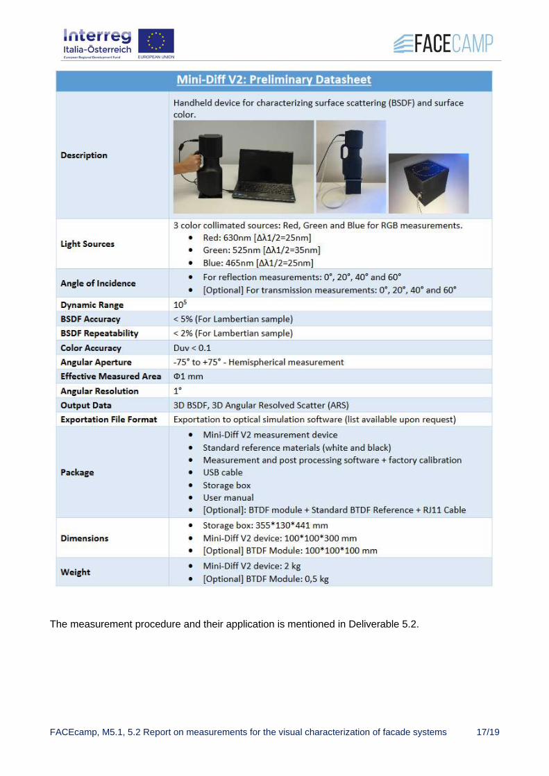
Mini Diff v2
www.lighttec.fr Key features Data format provided
by device software Laboratories
Portable equipment, easy to use and fast
Text files (ASTM, mesh, slice), Light Tools, Radiant Zemax, Speos, Trace Pro; ABg (Harvey Shack) and Gaussian fits
LightTec
Bartenbach
Description2:
- Angle of incidence: fixed at 0°, 20°, 40°, 60° (BRDF and BTDF) - Angular aperture: -75° to +75° (hemispherical measurement) - Light source: 3 colour collimated sources (RGB) at 465nm, 525nm and 630nm - Spot Size (diameter): 1mm - Wavelength detector sensitivity: 3 channels red, green and blue (RGB) - Dynamic range: 10e5 - BSDF Accuracy < 5% (for Lambertian sample)
2 LIGHT TEC: MINI-DIFF V2, for 2D/3D scattered light measurements, Preliminary datasheet. http://www.lighttec.fr/wp-content/uploads/2017/10/Flyer-Mini-Diff-V2.pdf (accessed 11 February 2020).
FACEcamp, M5.1, 5.2 Report on measurements for the visual characterization of facade systems 15/19
- BSDF Repeatability < 2% (for Lambertian sample) - Colour Accuracy Duv < 0.1 - Angular Aperture -75° to +75°
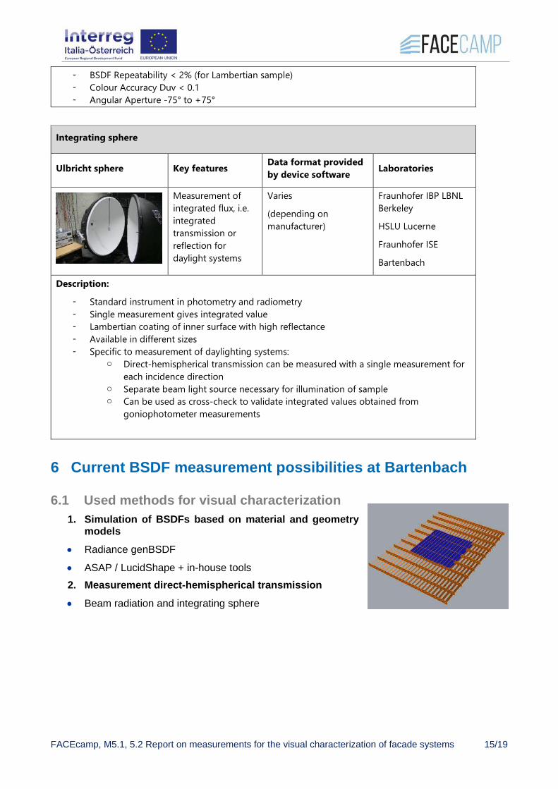
Integrating sphere
Ulbricht sphere Key features Data format provided by device software Laboratories
Measurement of integrated flux, i.e. integrated transmission or reflection for daylight systems
Varies
(depending on manufacturer)
Fraunhofer IBP LBNL Berkeley
HSLU Lucerne
Fraunhofer ISE
Bartenbach
Description:
- Standard instrument in photometry and radiometry - Single measurement gives integrated value - Lambertian coating of inner surface with high reflectance - Available in different sizes - Specific to measurement of daylighting systems:
o Direct-hemispherical transmission can be measured with a single measurement for each incidence direction
o Separate beam light source necessary for illumination of sample o Can be used as cross-check to validate integrated values obtained from
goniophotometer measurements
6 Current BSDF measurement possibilities at Bartenbach
6.1 Used methods for visual characterization 1. Simulation of BSDFs based on material and geometry
models • Radiance genBSDF
• ASAP / LucidShape + in-house tools 2. Measurement direct-hemispherical transmission • Beam radiation and integrating sphere

FACEcamp, M5.1, 5.2 Report on measurements for the visual characterization of facade systems 16/19
• Diffuse measurement luminaire
• Derivation of BSDF for non-scattering systems possible
3. Measurement of surface characteristics • new measurement device Mini-Diff
• V2 for BRDF and BTDF (full hemispherical)
• for any incident angle BRDF in the irradiation plane (only one cross section, time-consuming)
6.2 New measurement device: Mini-Diff V2 Mini-Diff V2 is a compact and portable optical system for 2D/3D scattering characterization: it can measure the BRDF & BTDF of different kind of materials and objects:
• Measurements of BSDF in red, green, and blue (RGB)
• TIS measurements for RGB
• Dynamic range is 1:105
• Colorimetric data: Lab or u'v'
Table 2: Datasheet of the measuring device Mini-Diff V2
Fig. 4: Visual characterization via simulations
Figure 7: Light Tec Mini-Diff V2
FACEcamp, M5.1, 5.2 Report on measurements for the visual characterization of facade systems 17/19
The measurement procedure and their application is mentioned in Deliverable 5.2.

FACEcamp, M5.1, 5.2 Report on measurements for the visual characterization of facade systems 18/19
7 References Kajiya J. T.: The rendering equation. SIGGRAPH Comput. Graph. 20, 4 (1986), 143–150. Nicodemus et al.: Geometrical Considerations and Nomenclature for Reflectance. NBS Monograph 160, U. S. Dept. of Commerce, 1977. Klems J.H.: A new method for predicting the solar heat gain of complex fenestration systems; Overview and derivation of the matrix layer calculation. ASHRAE Transactions 100 (1), 1994 CIE 108-1994: Guide to Recommended Practice of Daylight Measurement, 1994 Shirley P., Chiu K.: A Low Distortion Map between Map and Square, Journal of Graphics Tools 2(3), 1977 Ward G.: Presentations at the 10th Radiance Workshop, radiance-online.org/community/workshops/2011-berkeley-ca Ward G. et al.: „A Practical Framework for Sharing and Rendering Real-World Bidirectional Scattering Distribution Functions”, 2016

FACEcamp, M5.1, 5.2 Report on measurements for the visual characterization of facade systems 19/19
FACEcamp partners
EURAC Eurac Research, Institute for Renewable Energy
Coordinator
IDM IDM Suedtirol - Alto Adige Partner
UIBK Universität Innsbruck, Arbeitsbereich Energieeffizientes Bauen
Partner
HELLA HELLA Sonnen- und Wetterschutztechnik GmbH
Partner
BB, Bartenbach GmbH Partner
gA, Glassadvisor Srl Partner
F&R, FRENER & REIFER SrL Partner
Contact points: Project coordinator, Stefano Avesani [email protected] FACEcamp website www.facecamp.it Acknowledgement: This work is part of the research activities of the project FACEcamp n. ITAT1039, funded by European Regional Development Fund and Interreg ITA AUT programme.
Related Documents