DESIGN JOURNAL MODULE THREE: FABRICATION Jackson Wylie 638578 Sierra Stathis 640338

M3 jacksonwylie 638578
Mar 20, 2016
Module 3 - Fabrication Virtual Environments Semester 2 2013
Welcome message from author
This document is posted to help you gain knowledge. Please leave a comment to let me know what you think about it! Share it to your friends and learn new things together.
Transcript
DESIGN JOURNALMODULE THREE: FABRICATION
Jackson Wylie 638578 Sierra Stathis 640338

PRECEDENCEWINDE RIENSTRA, PETER ZUMTHOR AND LOUISE BOURGEOIS
We drew inspiration from Dutch designer Winde Rienstra, Swiss
architect Peter Zumthor and contemporary artist Louise Bourgeois.
Their work focuses on the skin and bone design concept. The
elements we used in our design were the ‘interior skin’ and ‘exterior
bone’ displayed in the Steilneset Museum and the geometric
fashion design and positioning of the shapes on the body.
This gives the inner skin the ability to look as though it is floating and
also creates some very unique shapes as the materials composing
the inner skin are stretched. In our design, we want the inner skin to
be stretched dramatically to create a very unique, organic shape.
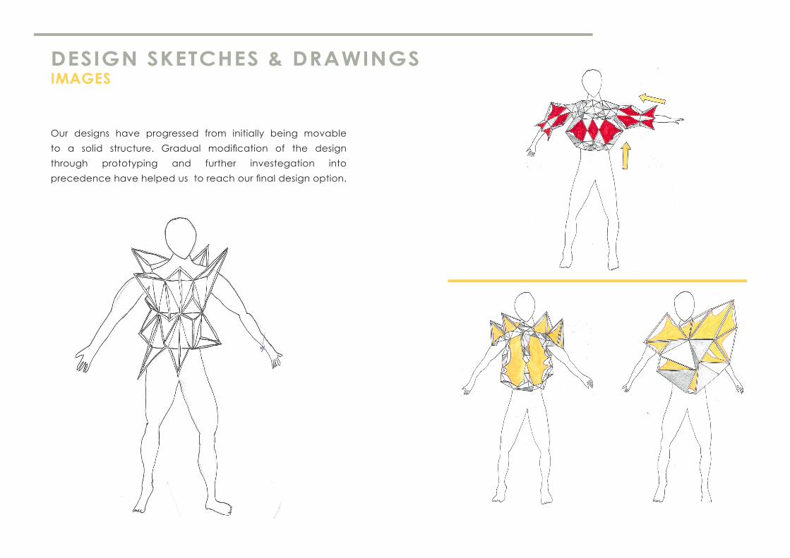
DESIGN SKETCHES & DRAWINGS IMAGES
Our designs have progressed from initially being movable
to a solid structure. Gradual modification of the design
through prototyping and further investegation into
precedence have helped us to reach our final design option.

DESIGN EVOLUTIONRHINO MODELS
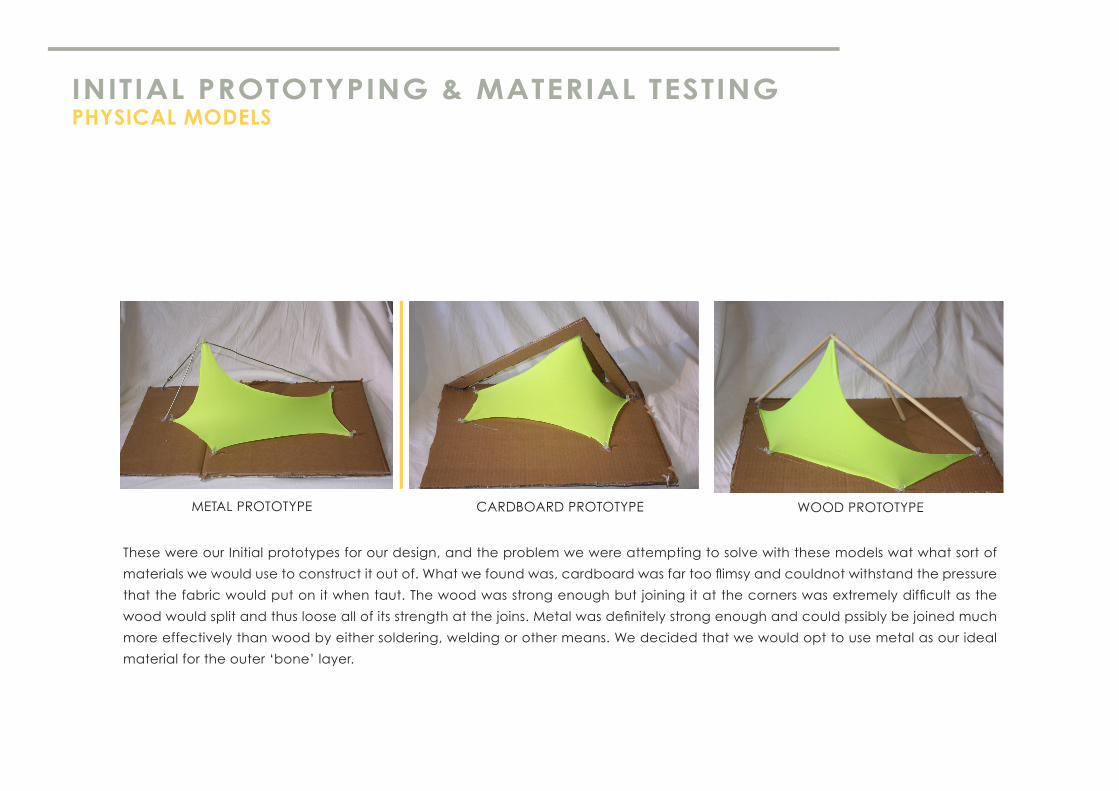
INITIAL PROTOTYPING & MATERIAL TESTINGPHYSICAL MODELS
These were our Initial prototypes for our design, and the problem we were attempting to solve with these models wat what sort of
materials we would use to construct it out of. What we found was, cardboard was far too flimsy and couldnot withstand the pressure
that the fabric would put on it when taut. The wood was strong enough but joining it at the corners was extremely difficult as the
wood would split and thus loose all of its strength at the joins. Metal was definitely strong enough and could pssibly be joined much
more effectively than wood by either soldering, welding or other means. We decided that we would opt to use metal as our ideal
material for the outer ‘bone’ layer.
CARDBOARD PROTOTYPEMETAL PROTOTYPE WOOD PROTOTYPE

FURTHER DEVELOPED PROTOTYPE& CHANGES IN DESIGN
After our decision to choose metal as the material for our ‘bone’
layer we came across a few technical challenges. First problem was
that most metals were quite heavy and this could result in the second
skin being very uncomfortable and difficult to wear for prolonged
periods of time and it may even impair the persons’ posture. We
solved this issure by choosing to use hollow aluminium tubing which
was extremely light. The second issue that we came across was
how we would join the aluminium tubing together and to the fabric.
Inspiration came from camping tents which share almost identical
frame material of hollow fibreglass or aluminium tubes, and they were
joined together quite effectively by elastic rope which runs through
the middle of it. This turned out to be a very effective way to join the
aluminum frame together and it also gave us something to anchor
the inside material to.

READING RESPONSE‘ARCHITECTURE IN THE DIGIAL AGE’-BRANDKO KOLAREVIC
& DIGITAL FABRICATION
Architecture in the dgital age explores how technological
advances completely evolved how people both conceve and
produce new designs. Whilst many architects and designers still
choose to brainstorm and initially ‘conceve‘ new designs via
sketches and drawings, digital technology has vadtly improved
the way in which these designs are ‘translated’ and produced,
digital programs allow pinpoint accuracy of geometry and with
modern 3D and 2D printers these extremely accurate designs
can now be produced into an identical physical structure.
Designs that are curved or highly complex can be much more
achievable to construct thanks to the aid of programs that
allow panelling and sectioning .

IMAGES AND MAKING PROCESSMETHOD: STAGE 1
The first step was ensuring all our materials
were collected and cut down to size. We
calculated the number and length of the
aluminium tube we needed. Important
element of building our model was ensuring
all the ends of the aluminium tubing was
blunted to ensure it wouldn’t cut the elasted
feeded through.
FRONT BASE FRAME BACK BASE FRAME

IMAGES AND MAKING PROCESSMETHOD: STAGE 2
Stage two added the 3D aspect of the model. The Triangles were added
individually using the same piece of elastic as the base frame to minimise
the visible knots and to ensure maximum strength. This process was quite
similar to the building of the base frame as it still involved running elastic
string through each of the aluminium pieces and securing them with a
knot at each of the pyramid’s pinnacle/intersect point.

IMAGES AND MAKING PROCESSMETHOD: STAGE 2 CONTINUED
After all of the pyramids were complete, the front and back pieces needed to be connected to complete the frame and make it wearable. This was done simply by adding two 20cm aluminium pieces between the top of the front and back pieces, and this was joined by doubling up the elastic string to strengthen these two pieces and allow the shoulders of the model to support the entire second skin’s weight.

IMAGES AND MAKING PROCESSSTAGE 3
Then the flexible skin layer could be added, this was the
most difficult part of the entire fabrication process. We
firstly cut generous estimates of how much fabric we
believes we would need for both the front and the back
(separately). For the front which we did first, we used
fishing line/wire to pitch the high point of the fabric to the
pinnacle vertices of each pyramid this is very similar to
the way in which the inner part of the steilneset memorial
is attached to the outer wooded frame structure. . We
then proceeded to stretch the fabric between each
pyramid to get rid of folds and slack areas of the fabric,
we found as we were doing this that it was also adding
strength to the overall second skin structure.
At the edges of the frames we cut all the excess fabric
away and folded it over the edge pieces of aluminium.
To secure the fabric to the edges of the frames we first
attempted to sew, this proves to be very difficult as it
was very time consuming, so instead we decided to
explore other ways in which we could secure the edges
of the fabric. Hot glue, was very quick however it did
leave a slight discoloration of the fabric which was not
ideal. Some other glues were more transparent however
took much longer to dry and this made joining the fabric
virtually impossible as the fabric needed to be taut. We
ended up sewing each corner of the fabric and glueing
the fabric to the metal in between. This approach
worked because the stitches at the corners held the
fabric in place, which gave the glue time to dry.
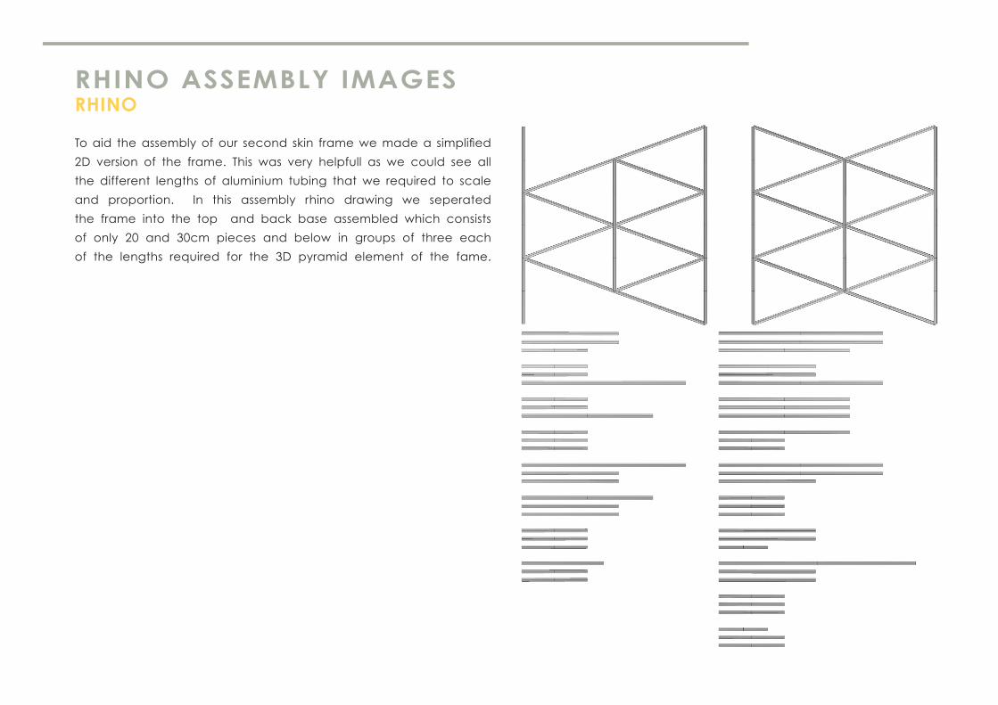
RHINO ASSEMBLY IMAGESRHINO
To aid the assembly of our second skin frame we made a simplified
2D version of the frame. This was very helpfull as we could see all
the different lengths of aluminium tubing that we required to scale
and proportion. In this assembly rhino drawing we seperated
the frame into the top and back base assembled which consists
of only 20 and 30cm pieces and below in groups of three each
of the lengths required for the 3D pyramid element of the fame.
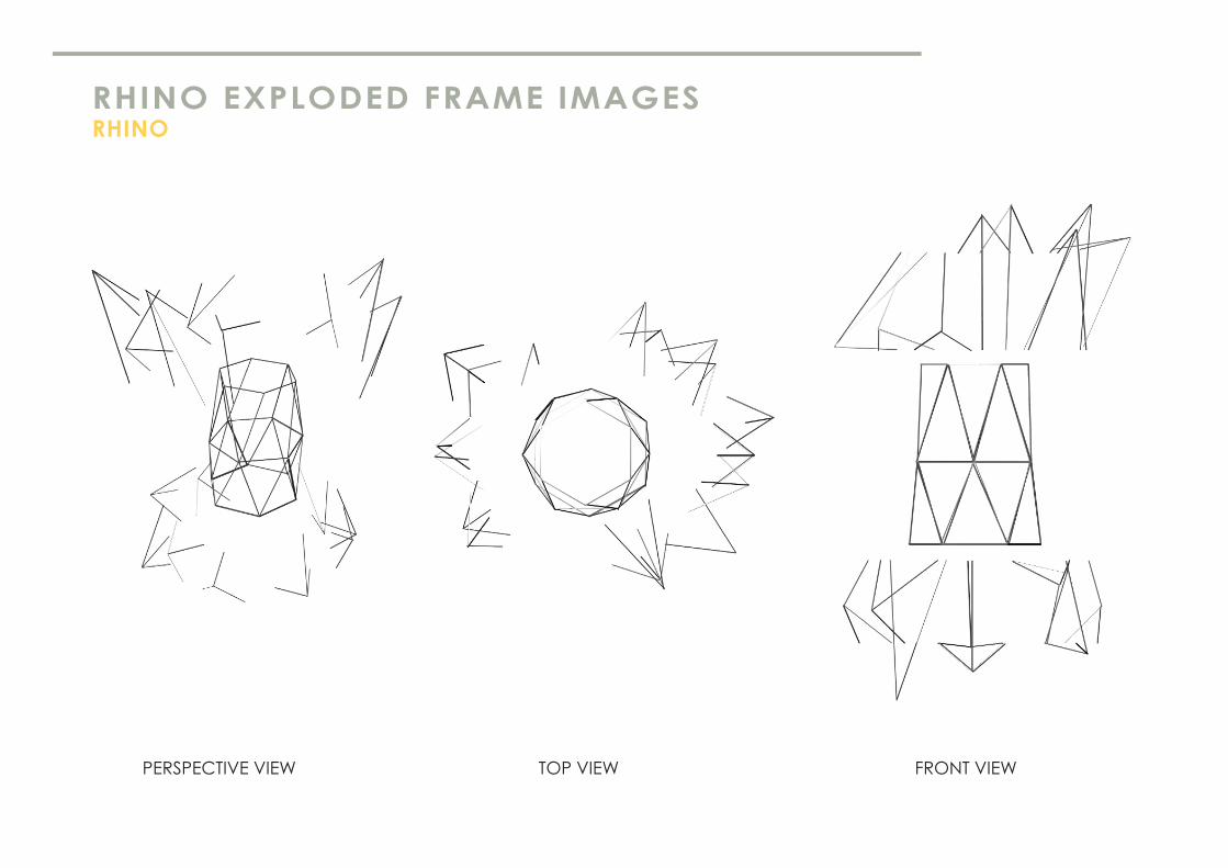
RHINO EXPLODED FRAME IMAGESRHINO
PERSPECTIVE VIEW TOP VIEW FRONT VIEW

FINAL RHINO DESIGNSSECOND SKIN

FINAL PHOTOSFRONT AND BACK
Related Documents