UCLA Radiology Fast Imaging Daniel B. Ennis, Ph.D. Magnetic Resonance Research Labs UCLA Radiology Class Business • Tuesday (3/7) from 6-9pm – 6:00-7:30pm Groups • Avanto – Sara Said, Yara Azar, April Pan • Skyra – Timothy Marcum, Diana Lopez, Zhaohuan Zhang • Prisma – Daisong Zhang, Jingwen Yao, Fang-Chu Lin, Andy Vuong – 7:30-9:00pm Groups • Avanto – Binru Chen, Junjie Chen, Yuhua Chen • Skyra – Jie Fu, Qihui Lyu, Cass Wong • Prisma – Nyasha Maforo, Fadil Ali, Vahid Ghodrati UCLA Radiology Class Business • HW #1 – 13.3±3.2 [15.75,6.5] • HW #2 – 11.7±2.6 [15, 6] • HW #3 – 13.7±1.4 [15, 9.5] • Class Average – 38.7±6.5 [46, 22.4]

Welcome message from author
This document is posted to help you gain knowledge. Please leave a comment to let me know what you think about it! Share it to your friends and learn new things together.
Transcript

UCLA Radiology
Fast Imaging
Daniel B. Ennis, Ph.D. Magnetic Resonance Research Labs
UCLA Radiology
Class Business• Tuesday (3/7) from 6-9pm
– 6:00-7:30pm Groups • Avanto
– Sara Said, Yara Azar, April Pan
• Skyra – Timothy Marcum, Diana Lopez, Zhaohuan Zhang
• Prisma – Daisong Zhang, Jingwen Yao, Fang-Chu Lin, Andy Vuong
– 7:30-9:00pm Groups • Avanto
– Binru Chen, Junjie Chen, Yuhua Chen
• Skyra – Jie Fu, Qihui Lyu, Cass Wong
• Prisma – Nyasha Maforo, Fadil Ali, Vahid Ghodrati
UCLA Radiology
Class Business• HW #1
– 13.3±3.2 [15.75,6.5] • HW #2
– 11.7±2.6 [15, 6]
• HW #3 – 13.7±1.4 [15, 9.5]
• Class Average – 38.7±6.5 [46, 22.4]

UCLARadiology
Lecture #14 - Learning Objectives
• Describe the origin and correction for several artifacts. • Understand the impact of spatial resolution and scan time on
signal-to-noise ratio. • Explain the importance of readout bandwidth and the +/- of
high (or low) readout bandwidth. • Define the origin, artifact, and possible correction for
chemical shift artifacts. • Appreciate why motion causes image artifacts in MRI • Be able to identify several artifacts in an MR image.
UCLARadiology
Lecture #15 - Learning Objectives
• Distinguish Type-1 and Type-2 chemical shift artifacts, their origin, and mitigation.
• Describe advantages and disadvantages of two partial fourier acquisition methods.
• Explain the advantages and disadvantages of multi-slice imaging.
• Explain the advantages and disadvantages of multi-echo imaging.
• Identify ways to improve imaging protocols.
Gradient Echoes & Fat

UCLA Radiology
x
GRE & Fat/Water Frequency
B0
Water Spins in a Uniform Field
UCLA Radiology
x
Water Spins in a Gradient Field
GRE & Fat/Water Frequency
B0
-Gx•x
+Gx•x
UCLA Radiology
x
GRE & Fat/Water Frequency
B0
-Gx•x
+Gx•x
Water & Fat Spins in a Gradient Field

UCLA Radiology
x
GRE & Fat/Water Frequency
B0
-Gx•x
+Gx•x
Signal Overlap
Signal Voids
UCLA Radiology
Low Bandwidth High Bandwidth
Pile-Up
Void
GRE & Fat/Water Frequency
• High Bandwidth – Less chemical shift – Lower SNR – Short TE/TR
• Low Bandwidth – More chemical shift – Higher SNR – Longer TE/TR
Type-1 Chemical Shift Artifact (spatial mis-registration).
UCLA Radiology
GRE and Fat/Water Phase• Pixels are frequently a mixture of fat and water • Pixel intensity is the vector sum of fat and water
Fat Water
+ >0In-Phase
+ =0Opposed-Phase
The TE controls the phase between fat and water.

UCLA Radiology
GRE and Fat/Water Phase• Pixels are frequently a mixture of fat and water • Pixel intensity is the vector sum of fat and water
The TE controls the phase between fat and water.
TEΦfat
T=1/f+π
-π
2.27 4.55 6.82 9.09 11.36 13.64 15.91 18.18
UCLA Radiology
GRE and Fat/Water PhaseIn-Phase Opposed-Phase
Type-2 Chemical Shift Artifact (aka India Ink artifact).
UCLA Radiology
Which image is the in-phase image?
Images Courtesy of Scott Reeder
A. B.

UCLA Radiology
Which image is the in-phase image?
Images Courtesy of Scott Reeder
In-Phase Opposed-PhaseA. B.
UCLA Radiology
Gradient Echoes & Fat Suppression
• Why is fat suppression/separation important? – Fat is bright on most pulse sequences. – But so are many other things...
• CSF & edema • Flowing blood • Contrast enhanced tissues
• Fat obscures underlying pathology – Edema, neoplasm, inflammation
• How can fat be eliminated in GRE images? – Fat saturation pulses – Multi-echo acquisitions
• Dixon/IDEAL
UCLA Radiology
Fat Suppression

UCLA RadiologyImages Courtesy of Scott Reeder
Fat-Sat Image
Fat-Sat Can Be Spatially Non-Uniform
Fat Suppression
UCLA Radiology
GRE & Fat/Water Separation - How?
RF
Slice Select
Phase Encode
Freq. Encode
TRTE1
TE1TE2
TE2
TE3
TE3
UCLA Radiology
RF
Slice Select
Phase Encode
Freq. Encode
TRTE1
TE1TE2
TE2
TE3
TE3
Fat/Water Reconstruction
GRE & Fat/Water Separation - How?

UCLA Radiology
Gradient Echoes & Fat/Water Separation
Images Courtesy of Scott Reeder
Water Image Fat Image
UCLA Radiology
Gradient Echoes & Fat/Water Separation
Images Courtesy of Dr. Scott Reeder
Imperfect Fat Sat
In-Phase Opposed-Phase
Water Image Fat Image
Partial Fourier Imaging

UCLA Radiology
Partial Fourier Imaging
kx
ky
kx
ky
Partial NEX Partial/Fractional EchoHow do you acquire each dataset?
What is an advantage/disadvantage to each approach?
UCLA Radiology
Hermitian Symmetry• If I(x) is real valued, then its frequency
representation S(k) is redundant. • If S(k) is known for k≥0, then S(k) for k<0 can be
generated according to:
• k-space is Hermitian (conjugate) symmetric.
S (�k) = S⇤ (k)
UCLA Radiology
Hermitian Symmetry
S (�kx,�ky,�kz) = S� (kx, ky, kz)
kx
ky

UCLA Radiology
S (kx, ky, kz) = Aei�
Hermitian Symmetry
• Every point in k-space has a magnitude and a phase • The phase of the signal at (kx,ky,kz), however, may
not be the same as the phase of the signal acquired at (-kx,-ky,-kz)
– Noise – Motion – Resonance frequency offsets – Hardware group delays – Eddy currents – Coil phases (Receive B1 inhomogeneity)
UCLA Radiology
Partial Fourier Imaging - Advantages• Readout Direction
– Reduced Echo Time (TE) • Improved SNR; Less T2* decay
– Reduced gradient moments • Reduced flow artifacts
• Phase Encode Direction – Reduced Scan Time
UCLA Radiology
Partial Fourier Imaging - Disadvantages• Lower SNR (faster scanning…) • Simple reconstruction (zero-filling)
– Blurring • Complex reconstruction (Homodyne or POCS)
– Increased recon time (trivial…) – Residual artifacts

2D Slice Interleaving
UCLA Radiology
Spin Echo
90°180°
RF
GSlice
GPhase
GReadout
Signal
TE
90°
TR
Wasted Time
UCLA Radiology
TR
Slice 3Slice 2
Spin Echo
90°
180°
RF
GSlice
GPhase
GReadout
Signal
TE
90°90°
180°
TE
90°
180°
TE
Slice 1

UCLA Radiology
Slice Interleaving
Adapted From Bernstein’s Handbook of MRI Pulse Sequences
Sequential 2D Imaging
Imaging Time = TR * NKy * NSlicesTime
...
Slice Interleaved 2D Imaging
Imaging Time = TR * NKy * NSlices / NInterleavesTime
...
k-space
UCLA Radiology
2D Slice Interleaving• Advantages
– Accelerate imaging by NInterleaves • Disadvantages
– Acceleration limited by • NInterleaves~TR/TE • SAR
– Difficult to acquire immediately adjacent slices • Hard to get good 180° slice-profile to match 90° slice-
profile for multi-slice imaging
• Applications – T2 imaging
• TR must be long (Why?) – DWI
• TR should be long
Multi-Echo Spin Echo Imaging

UCLA Radiology
How do we calculate scan time?
• TScan=1000ms•256•1=4:16 [mm:ss] • Assumes one echo per TR.
TScan = TR · PE ·Navg
UCLA Radiology
Spin Echo90°
180°
RF
GSlice
GPhase
GReadout
Signal
TE
90°
TR
UCLA Radiology
Spin Echo90°
180°
RF
GSlice
GPhase
GReadout
Signal
TE
90°
TR
Wasted Time

UCLA Radiology
Echo-1 Echo-3
Fast Spin Echo90°
180°
RF
GSlice
GPhase
GReadout
Signal
180° 180°
Echo-2
UCLA Radiology
Echo-3
Fast Spin Echo90°
180°
RF
GSlice
GPhase
GReadout
Signal
180° 180°
T2-decay
Echo-2Echo-1
UCLA Radiology
T2 Weighting (FSE vs. SE)
SEFSE
TR = 2500 TE = 116 ETL = 16 NEX = 2 24 slices Time = 2:51
TR = 2500 TE = 112
ETL = N/A NEX = 1 24 slices
Time = 22:21
Images Courtesy of Frank Korosec

UCLA Radiology
T1 Weighting (FSE)
Images Courtesy of Frank Korosec
ETL=4 ETL=16 ETL=24
Higher ETL reduces scan time, but introduces blurring.
UCLA Radiology
Fast Spin Echo• Advantages
– Turbo factor accelerates imaging – Can be used with 2D slice interleaving – Allows T2 weighted imaging in a breath hold
• Disadvantages – High turbo factors (ETL>4):
• Blur images • Alter image contrast
– Fat & Water are both bright on T2-weighted • Water/CSF T2 is long (~180ms) • Fat T2 is shorter (~85ms)
– Repeated 180s reduce spin-spin interaction – This “lengthens” the moderate T2 of fat
– SAR can be high
Spin Echo EPI
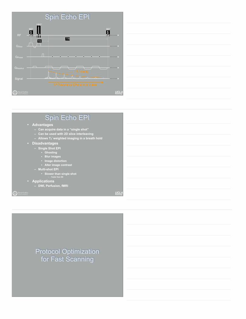
UCLA Radiology
Spin Echo EPI90°
180°
RF
GSlice
GPhase
GReadout
Signal
TE
90°
TR
T2*-decay
Off Resonance Effects Accumulate
UCLA Radiology
Spin Echo EPI• Advantages
– Can acquire data in a “single shot” – Can be used with 2D slice interleaving – Allows T2* weighted imaging in a breath hold
• Disadvantages – Single Shot EPI
• Ghosting • Blur images • Image distortion • Alter image contrast
– Multi-shot EPI • Slower than single shot
– Faster than SE
• Applications – DWI, Perfusion, fMRI
Protocol Optimization for Fast Scanning

UCLA Radiology
The Infeasible Protocol• T1-weighted GRE (FLASH)
– TR/TE/flip 162ms/4ms/30° – Matrix Size 256 (read) x 256 (phase) – FOV 480mm (read) x 480mm (phase) – Resolution 1.9mm x 1.9mm x 8mm – Acq. Time 43s (scanner reported) – rSNR 3.41
• Artifact - Breathing motion • Advantage - Abundant SNR • Disadvantage - Scan time too long
- Low Resolution
49
UCLA Radiology
The Infeasible Protocol
Resolution: 1.9 x 1.9 x 8mm – rSNR=3.41 – Scan Time=43s
50
UCLA Radiology
The Infeasible Protocol Cont’d
• T1-weighted GRE (FLASH) – TR/TE/flip 162ms/4ms/30° – Matrix Size 256 (read) x 256 (phase) – FOV 300mm (read) x 300mm (phase) – Resolution 1.2mm x 1.2mm x 8mm – Acq. Time 43s – rSNR 1.33
• Artifact - Breathing motion • Advantage - High SNR, Focused FOV • Disadvantage - Scan time too long
51

UCLA Radiology
Resolution: 1.2 x 1.2 x 8mm – rSNR=1.33 – Scan Time=43s
The Infeasible Protocol Cont’d
Frequency Encode Direction
FOV / 1
�k
52
Previously...
UCLA Radiology
Add Partial Phase FOV• T1-weighted GRE (FLASH)
– TR/TE/flip 162ms/4ms/30° – Matrix Size 256 (read) x 192 (phase) – FOV 300mm (read) x 225mm (phase) – Resolution 1.2mm x 1.2mm x 8mm – Acq. Time 33s – rSNR 1.15
• Artifact - Wrap, Breathing • Advantage - Reduced Scan Time • Disadvantage - Reduced SNR
- Scan time too long
53
UCLA Radiology
Add Partial Phase FOV
Resolution: 1.2 x 1.2 x 8mm – rSNR=1.15 – Scan Time=33s
54
Previously...

UCLA Radiology
Add 3/4 Partial Fourier• T1-weighted GRE (FLASH)
– TR/TE/flip 162ms/4ms/30° – Matrix Size 256 (read) x 144 (phase) – FOV 300mm (read) x 225mm (phase) – Resolution 1.2mm x 1.2mm x 8mm – Acq. Time 23s – rSNR 1.00
• Artifact - Subtle blurring • Advantage - Breath hold-able • Disadvantage - Decreased SNR
Protocol adapted from: Herborn CU, Vogt F, Lauenstein TC, Goyen M, Debatin JF, Ruehm SG. MRI of the liver: can True FISP replace HASTE? J Magn Reson Imaging. 2003;17(2):190-196.
55
UCLA Radiology
Add Partial Fourier
Resolution: 1.2 x 1.2 x 8mm – rSNR=1.0 – Scan Time=23s
56
Previously...
UCLA Radiology
Now what? Still 23-seconds!
• Can’t decrease FOV more. • Can’t increase partial Fourier fraction. • Could decrease TR
– Lower SNR – Altered T1 contrast
• Could increase bandwidth – This shortens the TE/TR slightly – Decreases SNR significantly
• Could decrease spatial resolution. – Blurs the images
57

UCLA Radiology
Asymmetric Voxels
• T1-weighted GRE (FLASH) – TR/TE/flip 162ms/4ms/30° – Matrix Size 256 (read) x 108 (phase) – FOV 300mm (read) x 225mm (phase) – Resolution 1.2mm x 1.6mm x 8mm – Acq. Time 19s – rSNR 1.33
• Artifact - Partial voluming • Advantage - Decreased scan time • Disadvantage - Low spatial resolution
58
UCLA Radiology
Asymmetric Voxels
Resolution: 1.2 x 1.6 x 8mm – rSNR=1.33 – Scan Time=19s
59
Previously...
UCLA Radiology
More Asymmetric Voxels
• T1-weighted GRE (FLASH) – TR/TE/flip 162ms/4ms/30° – Matrix Size 256 (read) x 72 (phase) – FOV 300mm (read) x 225mm (phase) – Resolution 1.2mm x 2.3mm x 8mm – Acq. Time 12s – rSNR 1.33
• Artifact - Partial voluming & blurring • Advantage - Decrease scan time
- Ample SNR • Disadvantage - Very low spatial resolution
60
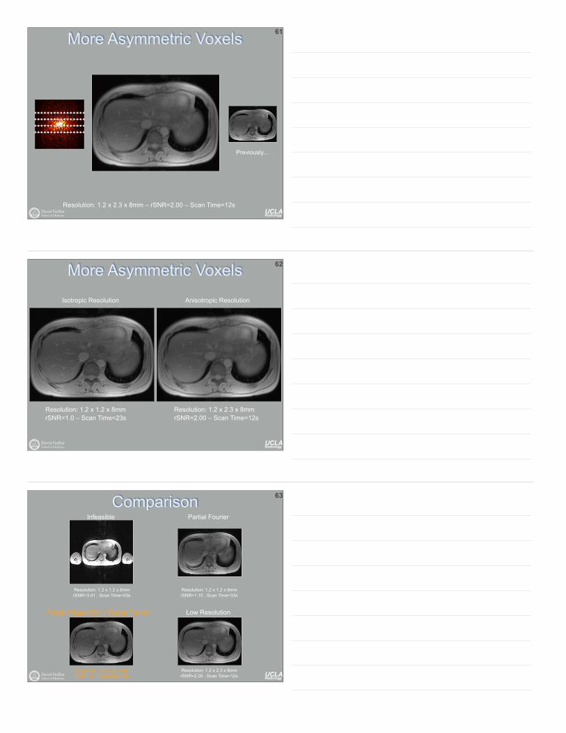
UCLA Radiology
More Asymmetric Voxels
Resolution: 1.2 x 2.3 x 8mm – rSNR=2.00 – Scan Time=12s
61
Previously...
UCLA Radiology
More Asymmetric Voxels
Resolution: 1.2 x 2.3 x 8mm rSNR=2.00 – Scan Time=12s
Resolution: 1.2 x 1.2 x 8mm rSNR=1.0 – Scan Time=23s
Isotropic Resolution Anisotropic Resolution
62
UCLA Radiology
Comparison
Resolution: 1.2 x 1.2 x 8mm rSNR=3.41 ; Scan Time=43s
Resolution: 1.2 x 1.2 x 8mm rSNR=1.15 ; Scan Time=33s
Resolution: 1.2 x 1.2 x 8mm rSNR=1.0 ; Scan Time=25s
Resolution: 1.2 x 2.3 x 8mm rSNR=2.00 ; Scan Time=12s
Infeasible Partial Fourier
Partial Phase FOV + Partial Fourier Low Resolution
63

UCLA Radiology
Conclusion
• Minimum k-space acquisition only... – Decreases scan time from 42s to 21s – Decreases rSNR by 3.41x
• BUT this is still sufficient... – Additional changes may compromise
• Image contrast • Spatial Resolution • Signal-to-noise
• These approaches still benefit from multi-echo and/or multi-slice acquisitions.
UCLA Radiology
Thanks
Daniel B. Ennis, Ph.D. [email protected] 310.206.0713 (Office) http://ennis.bol.ucla.edu
Peter V. Ueberroth Bldg. Suite 1417, Room C 10945 Le Conte Avenue
Related Documents


