860587211 Issue 1, March 2015 www.commscope.com M2000 Modular Panel Installation © 2015 CommScope, Inc. All rights reserved This product is covered by one or more U.S. patents or their foreign equivalents. For patents, see www.commscope.com/ProductPatent/ProductPatent.aspx Page 1 of 4 For RoHS Inquiries: CommScope Inc. Corke Abbey, Bray Co. Dublin, Ireland Attn: Legal Department General The CommScope ® M2000 modular panels for M-series outlets can be configured for copper, fiber, or both, and is available in 1U and 2U flat and angled versions. When installed with M-series outlets, modular patch cords and cables, it is an integral part of the CommScope ® connectivity system. The panel consists of a rack mounted base unit, rear cable management hardware, and labels for port numbering. Each panel mounts in a 19-inch (483mm) equipment rack with universal hole spacing. Ordering information is listed below: Material ID Catalog No. Description 760207274 M2000-1U 24-port modular flat panel - 1U 760207282 M2000-2U 48-port modular flat panel - 2U 760207290 M2000A-1U 24-port modular angled panel - 1U 760207308 M2000A-2U 48-port modular angled panel - 2U M2000-1U Flat Panel M2000A-1U Angled Panel How to Contact Us To find out more about CommScope ® products, visit us on the web at www.commscope.com/ For technical assistance: - Within the United States, contact your local account representative or technical support at 1-800-344-0223. Outside the United States, contact your local account representative or PartnerPRO ™ Network Partner. - Within the United States, report any missing/damaged parts or any other issues to CommScope Customer Claims at 1-866-539-2795 or email to [email protected]. Outside the United States, contact your local account representative or PartnerPRO Network Partner. Tools Required Phillips-head screwdriver

Welcome message from author
This document is posted to help you gain knowledge. Please leave a comment to let me know what you think about it! Share it to your friends and learn new things together.
Transcript

860587211 Issue 1, March 2015 www.commscope.com
M2000 Modular Panel Installation
© 2015 CommScope, Inc. All rights reserved
This product is covered by one or more U.S. patents or their foreign equivalents. For patents, see www.commscope.com/ProductPatent/ProductPatent.aspx
Page 1 of 4
For RoHS Inquiries:CommScope Inc.Corke Abbey, BrayCo. Dublin, IrelandAttn: Legal Department
General
The CommScope®
M2000 modular panels for M-series outlets can be configured for copper, fiber, or both, and is available in 1U and 2U flat and angled versions. When installed with M-series outlets, modular patch cords and cables, it is an integral part of the CommScope
® connectivity system. The panel consists of a rack mounted
base unit, rear cable management hardware, and labels for port numbering. Each panel mounts in a 19-inch (483mm) equipment rack with universal hole spacing.
Ordering information is listed below:
Material ID Catalog No. Description
760207274 M2000-1U 24-port modular flat panel - 1U
760207282 M2000-2U 48-port modular flat panel - 2U
760207290 M2000A-1U 24-port modular angled panel - 1U
760207308 M2000A-2U 48-port modular angled panel - 2U
M2000-1U Flat Panel M2000A-1U Angled Panel
How to Contact Us
To find out more about CommScope®
products, visit us on the web at www.commscope.com/
For technical assistance:
- Within the United States, contact your local account representative or technical support at 1-800-344-0223. Outside the United States, contact your local account representative or PartnerPRO
™ Network Partner.
- Within the United States, report any missing/damaged parts or any other issues to CommScope
Customer Claims at 1-866-539-2795 or email to [email protected]. Outside the United States, contact your local account representative or PartnerPRO Network Partner.
Tools Required
Phillips-head screwdriver

860587211 Instruction Sheet www.commscope.com
Page 2 of 4
Parts List
Verify parts against the parts list below:
Quantity Description
M2000-1U M2000A-1U M2000-2U M2000A-2U
1 – 1 – M2000 flat panel
– 1 – 1 M2000 angled panel
4 4 8 8 6-port bezel
1 1 2 2 Labels
1 1 2 2 Label retainers
4 4 4 4 Mounting screws, #12-24 x 1/2"
1 1 2 2 Rear cable management bar
4 4 8 8 Cable ties
1 1 1 1 Instruction sheet
WARNING – Important Safety Instructions
When using this product, the following basic safety precautions should be followed to reduce the risk of fire, electric shock, and injury to persons:
Never install communications wiring in wet locations unless it is designed for wet locations.
Never install this product during a lightning storm. There is a remote risk of electric shock.
Never touch uninsulated communication wiring or terminals unless the communication circuit has been disconnected at the network interface.
Caution: All wiring that connects to this equipment must meet applicable local and national building codes and network wiring standards for communication cable.
Step 1 ─ Mount Panel to Rack
1. Mount the M2000 panel to the rack using the four 12-24 x 1/2" screws provided. Orient panel as shown with the label areas positioned to the left of the outlet openings.
Rack
Panel
Panel
Mountingscrews (4 places)

www.commscope.com 860587211 Instruction Sheet
Page 3 of 4
Step 2 ─ Populate Panel
1. Populate panel with the appropriate information outlets after terminating per the instructions providedwith each outlet.
Step 3 ─ Install Cable Bar and Cables
1. Attach cable bar to rear of panel as shown above. For 48-port panels, two cable bars are provided.
2. Route cables evenly to cable management bar and secure using hook-and-loop straps as shown.
Cable bar
Cable tie
1U panel shown
Cablebar
Mountingslot
Cable bar
Panel rear
860587211 Instruction Sheet www.commscope.com
Page 4 of 4
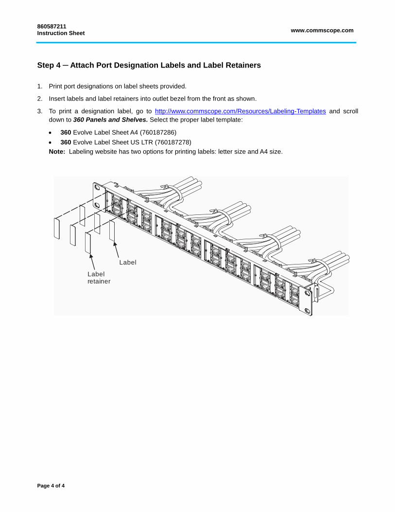
Step 4 ─ Attach Port Designation Labels and Label Retainers
1. Print port designations on label sheets provided.
2. Insert labels and label retainers into outlet bezel from the front as shown.
3. To print a designation label, go to http://www.commscope.com/Resources/Labeling-Templates and scroll
down to 360 Panels and Shelves. Select the proper label template:
360 Evolve Label Sheet A4 (760187286)
360 Evolve Label Sheet US LTR (760187278)
Note: Labeling website has two options for printing labels: letter size and A4 size.
Label
Labelretainer
Related Documents