M2 Antenna Systems, Inc. 4402 N. Selland Ave. Fresno, CA 93722 Tel: (559) 432-8873 Fax: (559) 432-3059 Web: www.m2inc.com ©2015 M2 Antenna Systems Incorporated 03/31/15 Rev.03 Model ........................................ 40M2L Frequency Range ...................... 6.9-10 MHz X 150 kHz Gain ........................................... 5.5 dBi Front to back.............................. 13 — 15 dB Beamwidth ............................... E=74° Feed type................................... Hair pin match Feed Impedance........................ 50 Ohms Unbalanced Maximum VSWR ....................... 1.2:1 Input Connector ......................... SO-239, Other avl. Power Handling ......................... 3 kW, Higher avl. Boom Length / Dia ..................... 19.5’ / 3.0 x .065 Wall Element Length / Dia. ................ 51 Ft. / 1-1/2” To 1/2” Turning Radius: ......................... 27 Ft. Stacking Distance ...................... 70 Ft. Mast Size ................................... 2” to 3 ” Nom. Wind area / Survival .................. 6.6 Sq. Ft. / 100 MPH Weight / Ship Wt. ....................... 62 Lbs. / 71 Lbs. M2 Antenna Systems, Inc. Model No: 40M2L SPECIFICATIONS: *Subtract 2.14 from dBi for dBd FEATURES: The recently upgraded, computer optimized, linear loaded, 40M2L Yagi has been designed to outperform and outlast all the “others”. It is now stronger mechanically and easier to assemble. Only the tips of each element are different as all the linear loading settings are the same for each element. The shorting bars are now 2 piece, clamp type making solid long lasting connections. The boom sections have been reconfigured to reduce shipping cost. Now every 40ML element in our 40 meter line utilizes identical, standardized components. This makes upgrading easier and tuning adjustments easy and consistant. The elements are butt sleeved and then joined with a SOLID rod of fiberglass or aluminum as the center cou- pling. Designed withstand continuous winds of 100 mph or just the constant battering of high winds, this antenna WILL frustrate Mother Nature! The linear loaded 3/16” diameter rods anchor at the center, 10” above the main element. This feature reduces inductive cancellation, element stress and droop. The 3/4” square 11” support riser is now 1/8 wall, fur- ther increasing the strength and lifetime of the Yagi. The Driven element is matched with an efficient hairpin and the the 3 kW continuous, 5 kW peak, :1 balun is supplied with the antenna. Four tuning options are provided to allow peak perfor- mance in your favorite part of the band. All hardware is stainless or galvanized except the U-bolts and remember every M 2 40ML Yagi is also available in our ruggedized, 125 mph “SURVIVOR” Series.

Welcome message from author
This document is posted to help you gain knowledge. Please leave a comment to let me know what you think about it! Share it to your friends and learn new things together.
Transcript
M2 Antenna Systems, Inc. 4402 N. Selland Ave. Fresno, CA 93722 Tel: (559) 432-8873 Fax: (559) 432-3059 Web: www.m2inc.com
©2015 M2 Antenna Systems Incorporated 03/31/15 Rev.03
Model ........................................ 40M2L Frequency Range ...................... 6.9-10 MHz X 150 kHz Gain ........................................... 5.5 dBi Front to back .............................. 13 — 15 dB Beamwidth ............................... E=74° Feed type ................................... Hair pin match Feed Impedance........................ 50 Ohms Unbalanced
Maximum VSWR ....................... 1.2:1 Input Connector ......................... SO-239, Other avl.
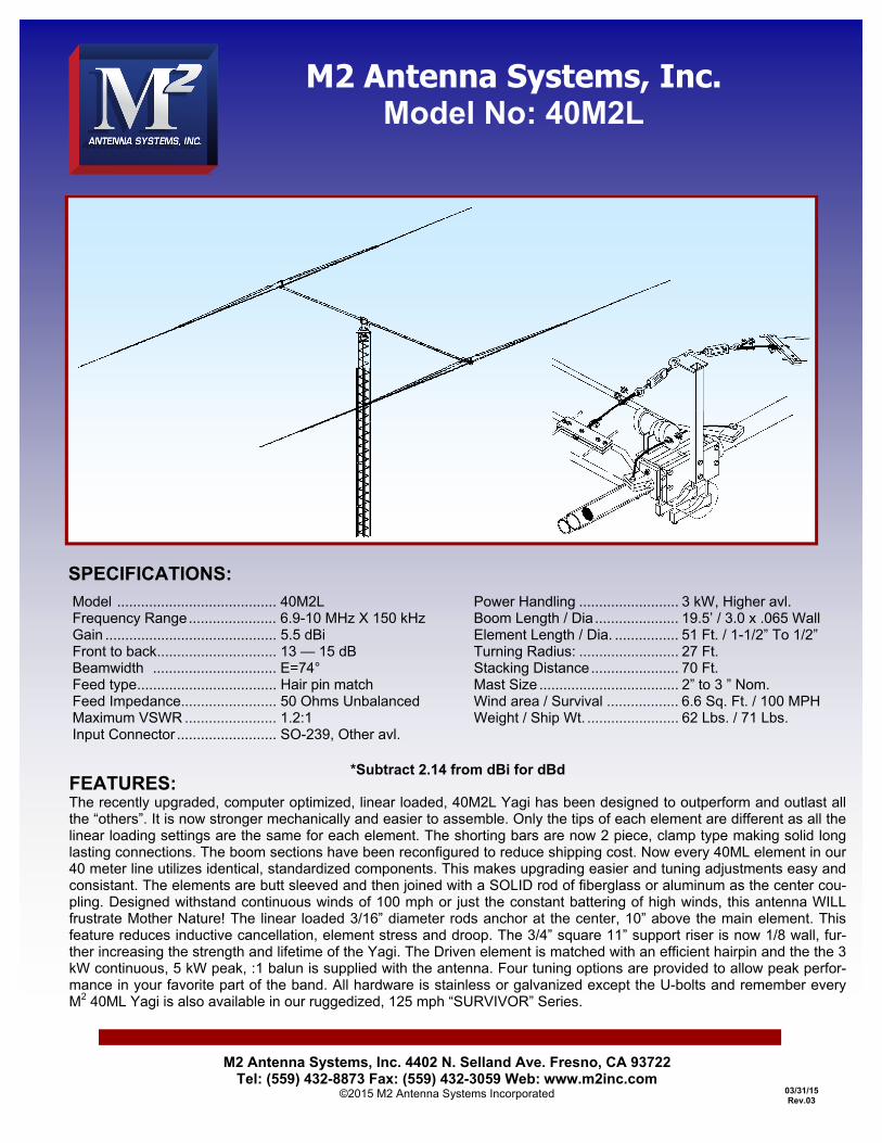
Power Handling ......................... 3 kW, Higher avl. Boom Length / Dia ..................... 19.5’ / 3.0 x .065 Wall Element Length / Dia. ................ 51 Ft. / 1-1/2” To 1/2” Turning Radius: ......................... 27 Ft. Stacking Distance ...................... 70 Ft. Mast Size ................................... 2” to 3 ” Nom. Wind area / Survival .................. 6.6 Sq. Ft. / 100 MPH Weight / Ship Wt. ....................... 62 Lbs. / 71 Lbs.
M2 Antenna Systems, Inc. Model No: 40M2L
SPECIFICATIONS:
*Subtract 2.14 from dBi for dBd FEATURES: The recently upgraded, computer optimized, linear loaded, 40M2L Yagi has been designed to outperform and outlast all the “others”. It is now stronger mechanically and easier to assemble. Only the tips of each element are different as all the linear loading settings are the same for each element. The shorting bars are now 2 piece, clamp type making solid long lasting connections. The boom sections have been reconfigured to reduce shipping cost. Now every 40ML element in our 40 meter line utilizes identical, standardized components. This makes upgrading easier and tuning adjustments easy and consistant. The elements are butt sleeved and then joined with a SOLID rod of fiberglass or aluminum as the center cou-pling. Designed withstand continuous winds of 100 mph or just the constant battering of high winds, this antenna WILL frustrate Mother Nature! The linear loaded 3/16” diameter rods anchor at the center, 10” above the main element. This feature reduces inductive cancellation, element stress and droop. The 3/4” square 11” support riser is now 1/8 wall, fur-ther increasing the strength and lifetime of the Yagi. The Driven element is matched with an efficient hairpin and the the 3 kW continuous, 5 kW peak, :1 balun is supplied with the antenna. Four tuning options are provided to allow peak perfor-mance in your favorite part of the band. All hardware is stainless or galvanized except the U-bolts and remember every M2 40ML Yagi is also available in our ruggedized, 125 mph “SURVIVOR” Series.
BEFORE YOU BEGIN: Look over the DIMENSION SHEET, HARDWARE AND ELEMENT ASSEMBLY DRAWINGS to get familiar with the various parts of the antenna. Tools handy for assembly process: screwdriver, 11/32, 7/16, 1/2, 9/16 and 5/8” nut drivers, end wrenches and/or sockets, diagonal cutters, and measuring tape. Small containers of zinc paste (Penetrox, Noalox, or equiv.) has been provided to enhance and maintain the quality of all electrical junctions on this antenna. Apply a thin coat wherever two pieces of aluminum come in contact or any other electrical connections are made. 1. ELEMENT CLAMP PLATE ASSEMBLY. SEE “ELEMENT HARDWARE” drawing to aid in the assembly of this step. Start by assembling the pairs of ELEMENT CLAMP PLATES together with 1/4-20 x 2-1/2" bolts to the four outer holes. NOTE THAT ONE SET OF CLAMP PLATES WILL ALSO GET A 1” X 1” X 6” ANGLE BRACKET FOR MOUNTING THE BALUN. Add the 1/4-20 locknuts finger tight. A. DRIVEN ELEMENT On one of the two element clamp plates assembled in the previous step, slip in the 1-1/4 X 24" fiberglass rods and rotate until the element mounting holes are vertical. Center the rod and tighten the hardware EVENLY, so the plates are parallel and the same amount of threads are showing through all the locknuts. Slide the POLYETHYLENE DISC INSULATORS onto both ends of the fiberglass rods and push them up against the clamp plates. The disc insulators can sometimes be a very tight fit on the rods. If you can’t get them to fit place them in hot water a few minutes. B. REFLECTOR ELEMENT Slide the 1-1/4” x 24” CENTER COUPLING ROD into a CLAMP PLATE ASSEMBLY. Center the assembly and align the bolt holes to vertical. Tighten all four outer element clamp plate bolts EVENLY. Make sure plates remain parallel, top to bottom. 2. VERTICAL SUPPORT POST INSTALLATION (SEE ELEMENT ASSEMBLY DETAIL PICTURES). The element clamps require a 1” SQ. X 24” WELDED VERTICAL SUPPORT POST to raise and support the linear loading lines and complete element assembly. Orient the WELDED PLATE over the element clamp plates. 3. HALF ELEMENT ASSEMBLIES See the ELEMENT ASSEMBLY drawing to aid in the assembly of each half element. Also refer to the DIMENSION SHEET and ELEMENT HARDWARE DETAIL drawings. Only the 1/2” element tip sections are different lengths. The correct hardware to join the various sizes are as follows: For 1-1/2" to 1-1/4" tubing use 8-32 x 1-3/4" screws. For 1-1/4" to 1" tubing use 8-32 x 1-1/2" screws. For 1" to 1“ and 1” to 3/4" tubing use 8-32 x 1-1/4" screws. For 3/4" to 1/2" tips use 5/8” compression clamps. Locknuts have been provided for all the element assembly screws. Tighten the nuts until the joint doesn't move when wiggled or shook. The element butt section closest to the boom always has one hole located at the butt for a 1/4-20 bolt. A. Prepare the LINEAR LOADING ARMS (1” center hole) with one 8-32 x 1/4” Allen head SET SCREW. (5/64 Allen wrench supplied), one 8-32 x 1-1/2” screw and locknut. Slide a LINEAR LOADING ARM on each 1" section and position it next to the end screw. Then slide the element overhead support clamp up against the 8-32 x 1-1/4” screws head nearest the end. Align it per the ELEMENT ASSEMBLY SHEET and tighten the 8-32 hardware securely.
40M2L ASSEMBLY MANUAL

B. Now slide the I” tube sections over the 7/8 x 9” fiberglass rod insulators. Connect the two sections with 8-32 x 1-1/4" screws and locknuts. Orient the arms as shown and tighten the 8-32 x 1-1/2 screws and locknuts. Be sure the arms are up against the screws closest to the fiberglass rod. THIS IS IMPORTANT SINCE THE ARMS ARE USED FOR DIMENSIONING THE LINEAR LOADING SHORTING BAR POSITION LATER IN THE ASSEMBLY
C. Locate the black plastic, 1” x 6” linear loading stabilizer bars. Attach them to the short 3/8” x 1-1/4”
x 3” support arm with the 1 inch hole. Use 8-32 x 1” screws and locknuts. Slide these on the SHORT, one inch element sections and position about 3” in from the butt. Now attach the 1-1/4” x 60” element sections. Add the 8-32 x 1-1/2” screws and locknuts but do not tighten until the STABALIZER BAR AND ARM ASSEMBLY ARE IN THE FINAL POSITION. Orient the black stabalizer bar insulators perpendicular to the element coupling holes and the support arms. Secure with 8-32 x 1-1/2” screws and locknuts. Repeat for the other element halves.
D. Insert the 3/4 x 48” sections into the swaged 1” sections and secure with 8-32 x 1-1/4 screws and
locknuts. NOW IS THE TIME TO DETERMINE WHAT PART OF THE BAND YOU WANT TO USE MOST AND EMPHASIZE. THE 4 BAND SEGMENTS INSURE VSWR UNDER 2:1 AND OPTIMUM GAIN & F/B. E. Following the DIMENSION SHEET, add the 1/2” tip sections in pairs, noting that each element has
different tip lengths. Secure with 5/8” compression clamps. F. As the outer element sections are being assembled, label each assembly as “REFLECTOR” , or
“DRIVEN”, ” (according to the 1/2” tips) to avoid mix ups. 4. REFLECTOR ASSEMBLY See ELEMENT HARDWARE drawing. Slide a 1-3/8” x 24" sleeve onto the 1-1/4” CENTER COUPLING ROD on the ELEMENT CLAMP ASSEMBLY, and align the 1/4” holes. Temporarily pin the sleeve as necessary. Carefully slide a 1-1/2” x 60” element section onto this assembly and align all holes. Insert a 1/4-20 x 2“ bolt and tighten securely with 1/4-20 locknut. Repeat for the other element half. Now add the reflector element outer half element assembly completed in the previous step to the 1-1/2" sections using 8-32 x 1-3/4" screws and locknuts. Repeat for the other element half. 5. DRIVEN ELEMENT ASSEMBLY See ELEMENT HARDWARE drawing. Slide a 1-3/8” x 24" sleeve onto each end of the 1-1/4” fiberglass rod on the remaining element clamp assemblies and align the 1/4” holes. Temporarily pin the sleeve as necessary. Carefully slide the 1-1/2” x 60” element butt onto the element mounting plate assemblies and align all holes. Locate 3/8” clamp blocks. Apply a little zinc paste to each of the channels. Loosely assemble the blocks, channel to channel. Install a 1/4-20 x 2-1/2” bolt up through the 1-1/2” element butt and drop the blocks over the stud. Add a locknut but do not tighten the hardware at this time. 6. Now add the driven element outer half element assembly completed in previous steps to the 1-1/2"
sections using 8-32 x 1-3/4" screws and locknuts. Repeat for the other element half.
40M2L ASSEMBLY MANUAL
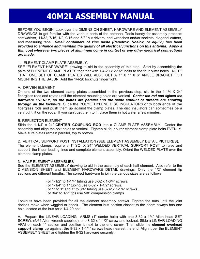
7. LINEAR LOADING ASSEMBLY – SEE ASSEMBLY DRAWINGS A. Install a pair of LINEAR LOADING RODS to each element half. Insert a rod through each
STABILIZER INSULATOR BAR and then through a LINEAR LOADING ARM, allowing about 3/4" to extend beyond the arm. Install 8-32 x 1/4" Allen head screws to lock rods in place and add 3/16” shaft retainers for extra safety.
B. Loosely assemble the LINEAR LOADING CLAMP PLATES (SHORTING BAR) pairs using 8-32 x 7/8” screws and locknuts.
C. Slide one set of these shorting bars on the ends of the 3/16” linear loading rods. Measure and mark the position for the shorting bars. Move the bars to that location and tighten one screw to hold position. Insert a short section of BLACK PHILISTRAN CABLE (HPTG1200) through one hole, around strain relief and back thru other hole of shorting bar then add 3/16” cable clip to secure it.
D. Align the rods and begin to tighten all the 8-32 x 7/8” screws and locknuts. Be sure the rods are parallel and have the same tension. Complete tightening the screws. Repeat for all the element halves.
E. Place the element on a level surface with support post "up." F. Prepare 1/4” HOOK AND EYE TURNBUCKLES by removing the hook end and running a 1/4-20
plain nut all the way to the hook. Now replace the hook end into the turnbuckle body and thread it in until just one thread shows inside the body of the turnbuckle. Now adjust the other end EYE of the turnbuckle until just one thread show inside the body.
G. Install 1/4" HOOK AND EYE TURNBUCKLES in the welded plates at the middle and at the top of the ELEMENT SUPPORTS. Install a CABLE EYE in the EYE of each turnbuckle and route the BLACK HPTG-1200 Philistran cable through the eye and back on itself. Review the element over head support clamp upgrade detail for proper routing of the BLACK PHILISTRAN CABLE (HPTG1200) to lock the cable to the clamp. Tension the element overhead support line and linear loading assembly and secure the cable with two cable clips on each line as shown. Repeat for remaining elements.
H. Now adjust the turnbuckles, adjusting so the inner sections are level and tighten the turnbuckle jam nuts. Element tips should droop about 4" to 8". The element will be more stable in the wind if you allow some droop to remain in the element.
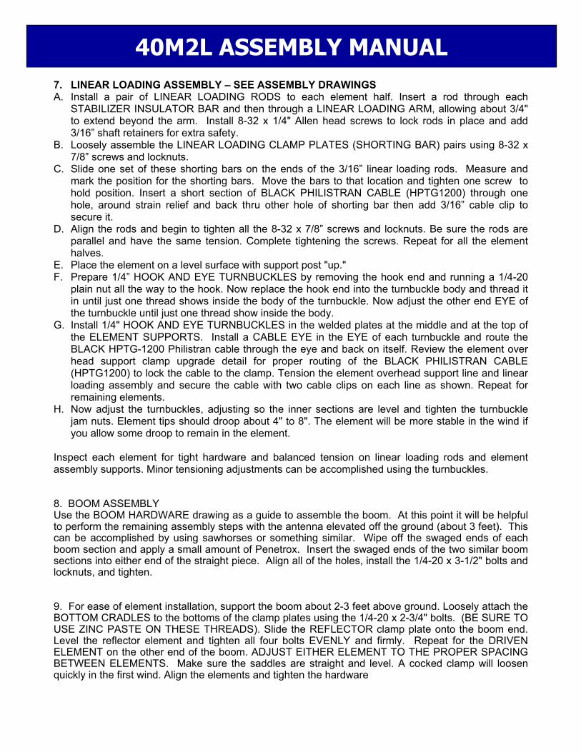
Inspect each element for tight hardware and balanced tension on linear loading rods and element assembly supports. Minor tensioning adjustments can be accomplished using the turnbuckles. 8. BOOM ASSEMBLY Use the BOOM HARDWARE drawing as a guide to assemble the boom. At this point it will be helpful to perform the remaining assembly steps with the antenna elevated off the ground (about 3 feet). This can be accomplished by using sawhorses or something similar. Wipe off the swaged ends of each boom section and apply a small amount of Penetrox. Insert the swaged ends of the two similar boom sections into either end of the straight piece. Align all of the holes, install the 1/4-20 x 3-1/2" bolts and locknuts, and tighten. 9. For ease of element installation, support the boom about 2-3 feet above ground. Loosely attach the BOTTOM CRADLES to the bottoms of the clamp plates using the 1/4-20 x 2-3/4" bolts. (BE SURE TO USE ZINC PASTE ON THESE THREADS). Slide the REFLECTOR clamp plate onto the boom end. Level the reflector element and tighten all four bolts EVENLY and firmly. Repeat for the DRIVEN ELEMENT on the other end of the boom. ADJUST EITHER ELEMENT TO THE PROPER SPACING BETWEEN ELEMENTS. Make sure the saddles are straight and level. A cocked clamp will loosen quickly in the first wind. Align the elements and tighten the hardware
40M2L ASSEMBLY MANUAL
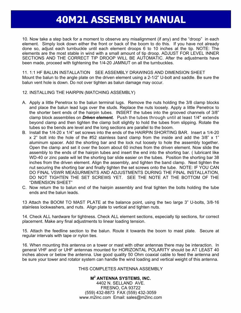
10. Now take a step back for a moment to observe any misalignment (if any) and the “droop” in each element. Simply look down either the front or back of the boom to do this. If you have not already done so, adjust each turnbuckle until each element droops 6 to 10 inches at the tip. NOTE: The elements are the most stable in wind with a small amount of tip droop. ADJUST FOR LEVEL INNER SECTIONS AND THE CORRECT TIP DROOP WILL BE AUTOMATIC. After the adjustments have been made, proceed with tightening the 1/4-20 JAMNUT on all the turnbuckles. 11. 1:1 HF BALUN INSTALLATION SEE ASSEMBLY DRAWINGS AND DIMENSION SHEET Mount the balun to the angle plate on the driven element using a 2-1/2” U-bolt and saddle. Be sure the balun vent hole is down. Do not over tighten as balun damage may occur. 12. INSTALLING THE HAIRPIN (MATCHING ASSEMBLY) A. Apply a little Penetrox to the balun terminal lugs. Remove the nuts holding the 3/8 clamp blocks
and place the balun lead lugs over the studs. Replace the nuts loosely. Apply a little Penetrox to the shorter bent ends of the hairpin tubes. INSERT the tubes into the grooved channels of 3/8” clamp block assemblies on Driven element. Push the tubes through until at least 1/4" extends beyond clamp and then tighten the clamp bolt slightly to hold the tubes from slipping. Rotate the tubes so the bends are level and the long sections are parallel to the boom.
B. Install the 1/4-20 x 1/4” set screws into the ends of the HAIRPIN SHORTING BAR. Insert a 1/4-20 x 2” bolt into the hole of the #52 stainless band clamp from the inside and add the 3/8” x 1” aluminum spacer. Add the shorting bar and the lock nut loosely to hole the assembly together. Open the clamp and set it over the boom about 60 inches from the driven element. Now slide the assembly to the ends of the hairpin tubes and insert the end into the shorting bar. ( lubricant like WD-40 or zinc paste will let the shorting bar slide easier on the tubes. Position the shorting bar 38 inches from the driven element. Align the assembly, and tighten the band clamp. Next tighten the nut securing the shorting bar and finally tighten the set screws onto the tube. NOTE: IF YOU CAN DO FINAL VSWR MEASURMENTS AND ADJUSTMENTS DURING THE FINAL INSTALLATION, DO NOT TIGHTEN THE SET SCREWS YET. SEE THE NOTE AT THE BOTTOM OF THE “DIMENSION SHEET”
C. Now return the to balun end of the hairpin assembly and final tighten the bolts holding the tube ends and the balun leads.
13 Attach the BOOM TO MAST PLATE at the balance point, using the two large 3” U-bolts, 3/8-16 stainless lockwashers, and nuts. Align plate to vertical and tighten nuts. 14. Check ALL hardware for tightness. Check ALL element sections, especially tip sections, for correct placement. Make any final adjustments to linear loading tension. 15. Attach the feedline section to the balun. Route it towards the boom to mast plate. Secure at regular intervals with tape or nylon ties. 16. When mounting this antenna on a tower or mast with other antennas there may be interaction. In general VHF and/ or UHF antennas mounted for HORIZONTAL POLARITY should be AT LEAST 40 inches above or below the antenna. Use good quality 50 Ohm coaxial cable to feed the antenna and be sure your tower and rotator system can handle the wind loading and vertical weight of this antenna.
THIS COMPLETES ANTENNA ASSEMBLY
M2 ANTENNA SYSTEMS, INC.
4402 N. SELLAND AVE. FRESNO, CA 93722
(559) 432-8873 FAX (559) 432-3059 www.m2inc.com Email: [email protected]
40M2L ASSEMBLY MANUAL
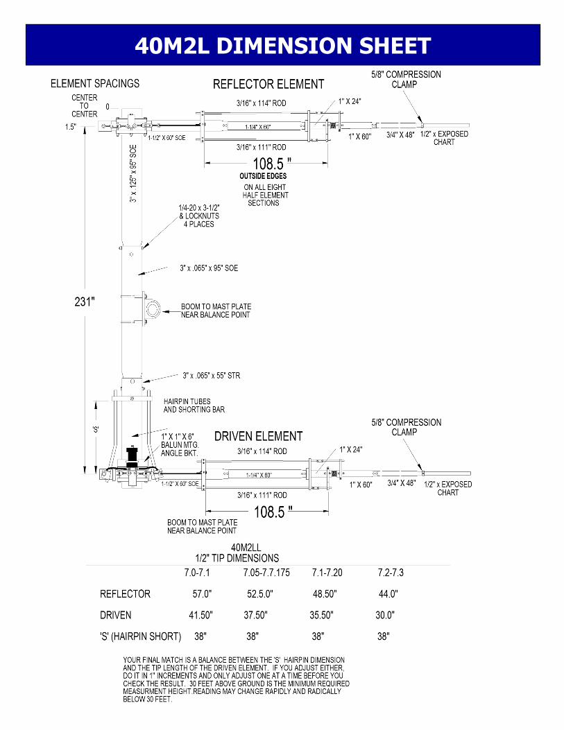
40M2L DIMENSION SHEET

FIG. #1
40M2L ASSEMBLY DETAIL

FIG. #1
40M2L ASSEMBLY DETAIL
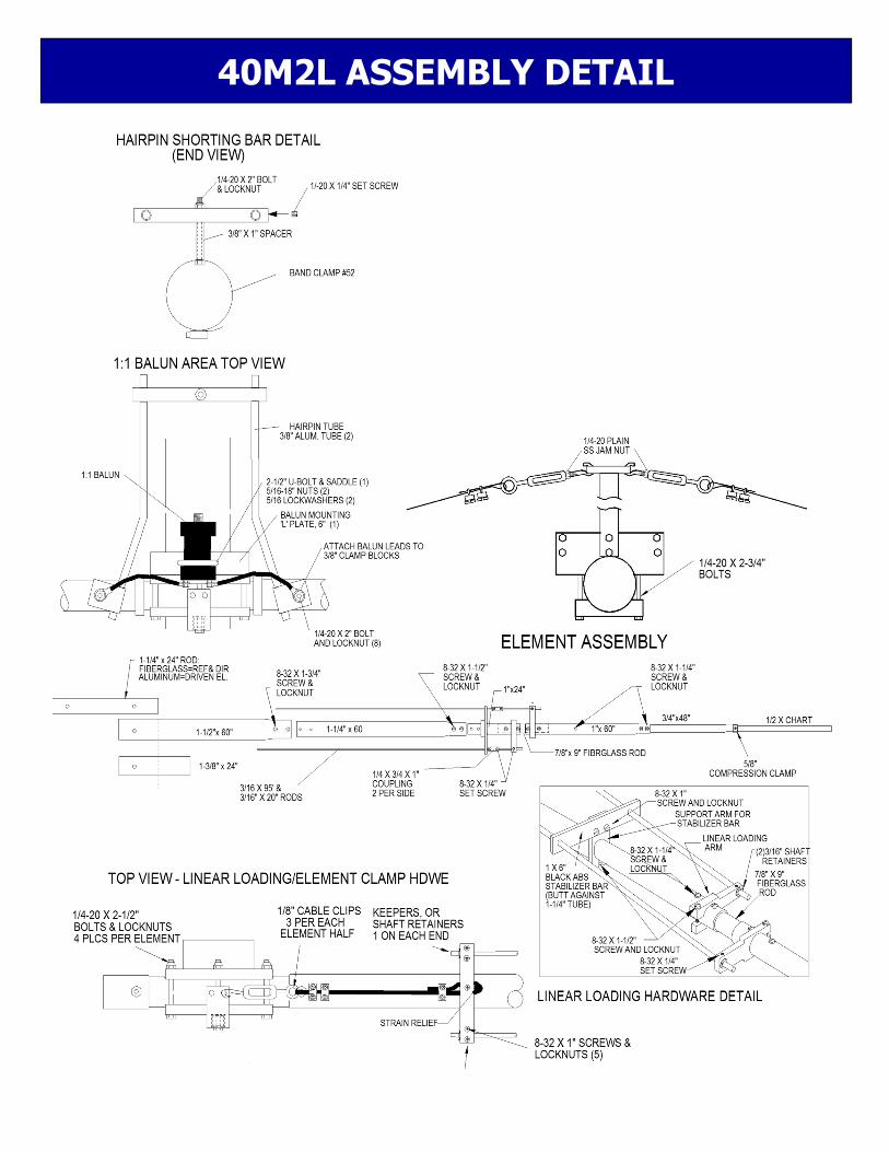
40M2L ASSEMBLY DETAIL
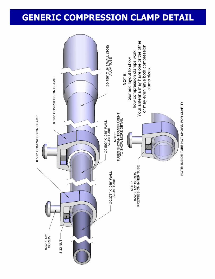
GENERIC COMPRESSION CLAMP DETAIL
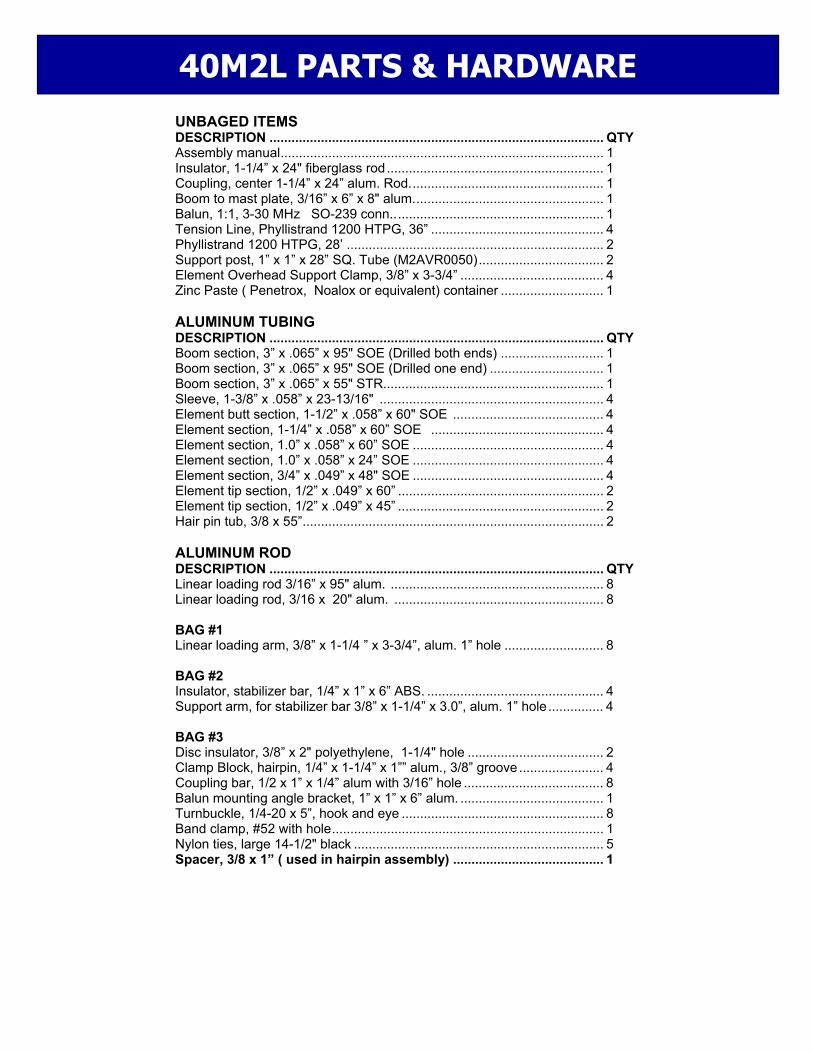
UNBAGED ITEMS DESCRIPTION ........................................................................................... QTY Assembly manual ........................................................................................ 1 Insulator, 1-1/4” x 24" fiberglass rod ........................................................... 1 Coupling, center 1-1/4” x 24” alum. Rod. .................................................... 1 Boom to mast plate, 3/16” x 6” x 8" alum. ................................................... 1 Balun, 1:1, 3-30 MHz SO-239 conn.. ........................................................ 1 Tension Line, Phyllistrand 1200 HTPG, 36” ............................................... 4 Phyllistrand 1200 HTPG, 28’ ...................................................................... 2 Support post, 1” x 1” x 28” SQ. Tube (M2AVR0050) .................................. 2 Element Overhead Support Clamp, 3/8” x 3-3/4” ....................................... 4 Zinc Paste ( Penetrox, Noalox or equivalent) container ............................ 1 ALUMINUM TUBING DESCRIPTION ........................................................................................... QTY Boom section, 3” x .065” x 95" SOE (Drilled both ends) ............................ 1 Boom section, 3” x .065” x 95" SOE (Drilled one end) ............................... 1 Boom section, 3” x .065” x 55" STR............................................................ 1 Sleeve, 1-3/8” x .058” x 23-13/16" ............................................................. 4 Element butt section, 1-1/2” x .058” x 60" SOE ......................................... 4 Element section, 1-1/4” x .058” x 60” SOE ............................................... 4 Element section, 1.0” x .058” x 60” SOE .................................................... 4 Element section, 1.0” x .058” x 24” SOE .................................................... 4 Element section, 3/4” x .049” x 48" SOE .................................................... 4 Element tip section, 1/2” x .049” x 60” ........................................................ 2 Element tip section, 1/2” x .049” x 45” ........................................................ 2 Hair pin tub, 3/8 x 55” .................................................................................. 2 ALUMINUM ROD DESCRIPTION ........................................................................................... QTY Linear loading rod 3/16” x 95" alum. .......................................................... 8 Linear loading rod, 3/16 x 20" alum. ......................................................... 8 BAG #1 Linear loading arm, 3/8” x 1-1/4 ” x 3-3/4”, alum. 1” hole ........................... 8 BAG #2 Insulator, stabilizer bar, 1/4” x 1” x 6” ABS. ................................................ 4 Support arm, for stabilizer bar 3/8” x 1-1/4” x 3.0”, alum. 1” hole ............... 4 BAG #3 Disc insulator, 3/8” x 2" polyethylene, 1-1/4" hole ..................................... 2 Clamp Block, hairpin, 1/4” x 1-1/4” x 1”” alum., 3/8” groove ....................... 4 Coupling bar, 1/2 x 1” x 1/4” alum with 3/16” hole ...................................... 8 Balun mounting angle bracket, 1” x 1” x 6” alum. ....................................... 1 Turnbuckle, 1/4-20 x 5”, hook and eye ....................................................... 8 Band clamp, #52 with hole .......................................................................... 1 Nylon ties, large 14-1/2" black .................................................................... 5 Spacer, 3/8 x 1” ( used in hairpin assembly) ......................................... 1
40M2L PARTS & HARDWARE

BAG #4 Shorting bar, 1/4” x 3/4” x 6" ....................................................................... 8 Phase Line Strain Relief, .500 DIA. X .500 BLK DELRIN ........................... 4 Shorting bar, hairpin, 1/2 x 1/2 x 5” ........................................................... 1 BAG #5 Saddle Clamp, 1/2” x 1.0” x 4" alum (for 3” dia.). ........................................ 4 Element Clamp plate, 1/2” x 3” x 6", 5/8” radius, alum #6 .......................... 4 BAG #6 Fiberglass rod, 7/8” x 9” with 4 holes .......................................................... 4 BAG #7 U-bolt, 3" ..................................................................................................... 2 U-bolt, 2-1/2" ............................................................................................... 1 U-bolt, 2", ................................................................................................... 4 BAG #8 Nut, 3/8-16 stainless ................................................................................... 4 Lock washer, 3/8" split ring stainless .......................................................... 4 Nut, 5/16-18, stainless ................................................................................ 10 Lock washer, 5/16" split ring, stainless ....................................................... 10 Bolt, 1/4-20 x 3-1/2" stainless ..................................................................... 8 Bolt, 1/4-20 x 2-3/4" stainless ..................................................................... 8 Bolt, 1/4-20 x 2-1/2" stainless ..................................................................... 10 Bolt, 1/4-20 x 2.0" stainless ......................................................................... 3 Set screws, 1/4-20 x 1/4”,ss ........................................................................ 2 Nut, 1/4-20”, stainless ................................................................................. 4 Nut, 1/4-20 locking, stainless ...................................................................... 21 Allen wrench, 1/8” ....................................................................................... 1 BAG #9 5/8” Compression Clamp ............................................................................ 4 Screw, 8-32 x 1-3/4” panhead, stainless ..................................................... 8 Screw, 8-32 x 1-1/2" panhead, stainless .................................................... 24 Screw, 8-32 x 1-1/4" panhead, stainless .................................................... 24 Screw, 8-32 x 1.0" panhead, stainless ........................................................ 28 Screw, 8-32 x 1/2" panhead, stainless ........................................................ 4 Nut, 8-32 locking, stainless ......................................................................... 86 Nut, 8-32, stainless ..................................................................................... 4 Set screw, 8-32 x 1/4” stainless ................................................................. 24 Shaft retainer, 3/16” stainless ..................................................................... 16 Push tube 3/8” x 3" alum. ............................................................................ 1 Allen wrench 5/64” ...................................................................................... 2 Cable Clips, 1/8” .......................................................................................... 20 Small Cable Eyes, 1/8” ................................................................................ 8
M2 ANTENNA SYSTEMS, INC. 4402 N. SELLAND AVE.
FRESNO, CA 93722 (559) 432-8873 FAX (559) 432-3059
www.m2inc.com Email: [email protected]
40M2L PARTS & HARDWARE
Related Documents