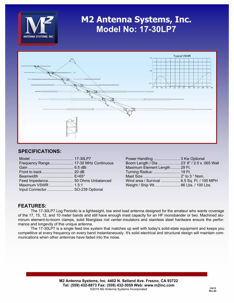
M2 Antenna Systems, Inc. 4402 N. Selland Ave. Fresno, CA 93722 Tel: (559) 432-8873 Fax: (559) 432-3059 Web: www.m2inc.com ©2015 M2 Antenna Systems Incorporated 1/9/15 Rev.00 Model ........................................ 17-30LP7 Frequency Range ...................... 17-30 MHz Continuous Gain ........................................... 6.5 dBi Front to back.............................. 20 dB Beamwidth ............................... E=65° Feed Impedance........................ 50 Ohms Unbalanced Maximum VSWR ....................... 1.5:1 Input Connector ......................... SO-239 Optional Power Handling ......................... 3 Kw Optional Boom Length / Dia ..................... 23’ 8” / 2.0 x .065 Wall Maximum Element Length ......... 29 Ft. Turning Radius: ......................... 19 Ft. Mast Size ................................... 2” to 3 ” Nom. Wind area / Survival .................. 6.5 Sq. Ft. / 100 MPH Weight / Ship Wt. ....................... 86 Lbs. / 100 Lbs. M2 Antenna Systems, Inc. Model No: 17-30LP7 FEATURES: The 17-30LP7 Log Periodic is a lightweight, low wind load antenna designed for the amateur who wants coverage of the 17, 15, 12, and 10 meter bands and still have enough mast capacity for an HF monobander or two. Machined alu- minum element-to-boom clamps, solid fiberglass rod center-insulators and stainless steel hardware ensure the perfor- mance and longevity of this unique antenna. The 17-30LP7 is a single feed line system that matches up well with today's solid-state equipment and keeps you competitive at every frequency on every band instantaneously. It's solid electrical and structural design will maintain com- munications when other antennas have faded into the noise. SPECIFICATIONS:

Welcome message from author
This document is posted to help you gain knowledge. Please leave a comment to let me know what you think about it! Share it to your friends and learn new things together.
Transcript
M2 Antenna Systems, Inc. 4402 N. Selland Ave. Fresno, CA 93722 Tel: (559) 432-8873 Fax: (559) 432-3059 Web: www.m2inc.com
©2015 M2 Antenna Systems Incorporated 1/9/15 Rev.00
Model ........................................ 17-30LP7 Frequency Range ...................... 17-30 MHz Continuous Gain ........................................... 6.5 dBi Front to back .............................. 20 dB Beamwidth ............................... E=65° Feed Impedance........................ 50 Ohms Unbalanced
Maximum VSWR ....................... 1.5:1 Input Connector ......................... SO-239 Optional
Power Handling ......................... 3 Kw Optional Boom Length / Dia ..................... 23’ 8” / 2.0 x .065 Wall Maximum Element Length ......... 29 Ft. Turning Radius: ......................... 19 Ft. Mast Size ................................... 2” to 3 ” Nom. Wind area / Survival .................. 6.5 Sq. Ft. / 100 MPH Weight / Ship Wt. ....................... 86 Lbs. / 100 Lbs.
M2 Antenna Systems, Inc. Model No: 17-30LP7
FEATURES: The 17-30LP7 Log Periodic is a lightweight, low wind load antenna designed for the amateur who wants coverage of the 17, 15, 12, and 10 meter bands and still have enough mast capacity for an HF monobander or two. Machined alu-minum element-to-boom clamps, solid fiberglass rod center-insulators and stainless steel hardware ensure the perfor-mance and longevity of this unique antenna. The 17-30LP7 is a single feed line system that matches up well with today's solid-state equipment and keeps you competitive at every frequency on every band instantaneously. It's solid electrical and structural design will maintain com-munications when other antennas have faded into the noise.
SPECIFICATIONS:
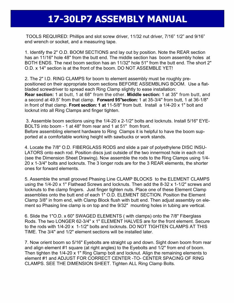
TOOLS REQUIRED: Phillips and slot screw driver, 11/32 nut driver, 7/16” 1/2” and 9/16” end wrench or socket, and a measuring tape. 1. Identify the 2" O.D. BOOM SECTIONS and lay out by position. Note the REAR section has an 11/16" hole 48" from the butt end. The middle section has boom assembly holes at BOTH ENDS. The next boom section has an 11/32" hole 51" from the butt end. The short 2" O.D. x 14" section is at the front of the boom. DO NOT ASSEMBLE YET! 2. The 2" I.D. RING CLAMPS for boom to element assembly must be roughly pre-positioned on their appropriate boom sections BEFORE ASSEMBLING BOOM. Use a flat-bladed screwdriver to spread each Ring Clamp slightly to ease installation: Rear section: 1 at butt, 1 at 68" from the other. Middle section: 1 at 35" from butt, and a second at 49.5” from that clamp. Forward 95"section: 1 at 35-3/4" from butt, 1 at 36-1/8" in front of that clamp. Front section: 1 at 11-5/8" from butt. Install a 1/4-20 x 1" bolt and locknut into all Ring Clamps and finger tighten.
3. Assemble boom sections using the 1/4-20 x 2-1/2" bolts and locknuts. Install 5/16" EYE-BOLTS into boom - 1 at 48" from rear and 1 at 51" from front. Before assembling element hardware to Ring Clamps it is helpful to have the boom sup-ported at a comfortable working height with sawbucks or work stands. 4. Locate the 7/8" O.D. FIBERGLASS RODS and slide a pair of polyethylene DISC INSU-LATORS onto each rod. Position discs just outside of the two innermost hole in each rod (see the Dimension Sheet Drawing). Now assemble the rods to the Ring Clamps using 1/4-20 x 1-3/4" bolts and locknuts. The 3 longer rods are for the 3 REAR elements, the shorter ones for forward elements. 5. Assemble the small grooved Phasing Line CLAMP BLOCKS to the ELEMENT CLAMPS using the 1/4-20 x 1" Flathead Screws and locknuts. Then add the 8-32 x 1-1/2" screws and locknuts to the clamp fingers. Just finger tighten nuts. Place one of these Element Clamp assemblies onto the butt end of each 1" O.D. ELEMENT SECTION. Position the Element Clamp 3/8" in from end, with Clamp Block flush with butt end. Then adjust assembly on ele-ment so Phasing line clamp is on top and the 9/32" mounting holes in tubing are vertical. 6. Slide the 1"O.D. x 60" SWAGED ELEMENTS ( with clamps) onto the 7/8" Fiberglass Rods. The two LONGER 62-3/4" x 1" ELEMENT HALVES are for the front element. Secure to the rods with 1/4-20 x 1-1/2" bolts and locknuts. DO NOT TIGHTEN CLAMPS AT THIS TIME. The 3/4" and 1/2" element sections will be installed later. 7. Now orient boom so 5/16" Eyebolts are straight up and down. Sight down boom from rear and align element #1 square (at right angles) to the Eyebolts and 1/2" from end of boom. Then tighten the 1/4-20 x 1" Ring Clamp bolt and locknut. Align the remaining elements to element #1 and ADJUST FOR CORRECT CENTER -TO- CENTER SPACING OF RING CLAMPS. SEE THE DIMENSION SHEET. Tighten ALL Ring Clamp Bolts.
17-30LP7 ASSEMBLY MANUAL
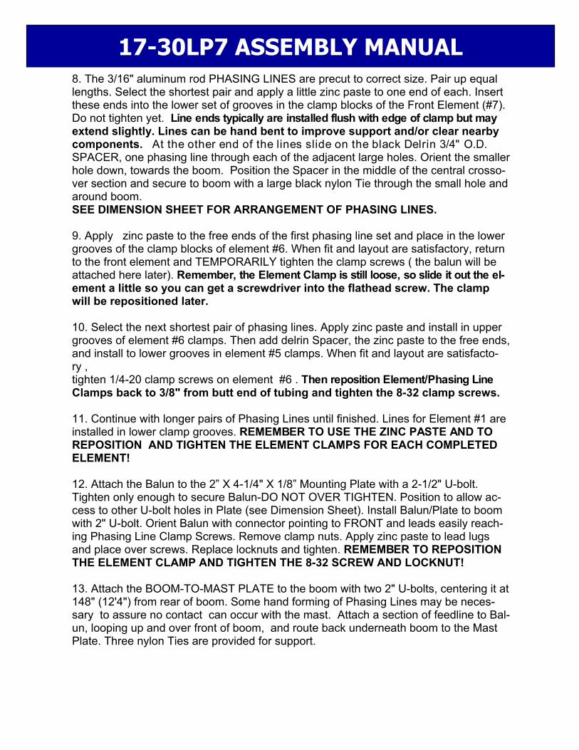
8. The 3/16" aluminum rod PHASING LINES are precut to correct size. Pair up equal lengths. Select the shortest pair and apply a little zinc paste to one end of each. Insert these ends into the lower set of grooves in the clamp blocks of the Front Element (#7). Do not tighten yet. Line ends typically are installed flush with edge of clamp but may extend slightly. Lines can be hand bent to improve support and/or clear nearby components. At the other end of the lines slide on the black Delrin 3/4" O.D. SPACER, one phasing line through each of the adjacent large holes. Orient the smaller hole down, towards the boom. Position the Spacer in the middle of the central crosso-ver section and secure to boom with a large black nylon Tie through the small hole and around boom. SEE DIMENSION SHEET FOR ARRANGEMENT OF PHASING LINES. 9. Apply zinc paste to the free ends of the first phasing line set and place in the lower grooves of the clamp blocks of element #6. When fit and layout are satisfactory, return to the front element and TEMPORARILY tighten the clamp screws ( the balun will be attached here later). Remember, the Element Clamp is still loose, so slide it out the el-ement a little so you can get a screwdriver into the flathead screw. The clamp will be repositioned later. 10. Select the next shortest pair of phasing lines. Apply zinc paste and install in upper grooves of element #6 clamps. Then add delrin Spacer, the zinc paste to the free ends, and install to lower grooves in element #5 clamps. When fit and layout are satisfacto-ry , tighten 1/4-20 clamp screws on element #6 . Then reposition Element/Phasing Line Clamps back to 3/8" from butt end of tubing and tighten the 8-32 clamp screws. 11. Continue with longer pairs of Phasing Lines until finished. Lines for Element #1 are installed in lower clamp grooves. REMEMBER TO USE THE ZINC PASTE AND TO REPOSITION AND TIGHTEN THE ELEMENT CLAMPS FOR EACH COMPLETED ELEMENT! 12. Attach the Balun to the 2” X 4-1/4" X 1/8” Mounting Plate with a 2-1/2" U-bolt. Tighten only enough to secure Balun-DO NOT OVER TIGHTEN. Position to allow ac-cess to other U-bolt holes in Plate (see Dimension Sheet). Install Balun/Plate to boom with 2" U-bolt. Orient Balun with connector pointing to FRONT and leads easily reach-ing Phasing Line Clamp Screws. Remove clamp nuts. Apply zinc paste to lead lugs and place over screws. Replace locknuts and tighten. REMEMBER TO REPOSITION THE ELEMENT CLAMP AND TIGHTEN THE 8-32 SCREW AND LOCKNUT! 13. Attach the BOOM-TO-MAST PLATE to the boom with two 2" U-bolts, centering it at 148" (12'4") from rear of boom. Some hand forming of Phasing Lines may be neces-sary to assure no contact can occur with the mast. Attach a section of feedline to Bal-un, looping up and over front of boom, and route back underneath boom to the Mast Plate. Three nylon Ties are provided for support.
17-30LP7 ASSEMBLY MANUAL

14. For completing element assembly, refer to Dimension Sheet. Install 3/4" Ele-ment sections to 1" sections with 8-32 x 1-1/4" screws and locknuts. Note the three rear elements use full length 3/4" x 60 " sections. Custom 3/4" lengths are used on elements #4, 5, and 6 (None on #7). The 1/2" Element sections are installed on ele-ments #1, 2, and 3 with 5/8” compression clamps (SEE COMPRESSION CLAMP & ASSEMBLY DETAIL PAGE AND DIMENSION SHEET). OVERHEAD BOOM SUPPORT SYSTEM 15. Attach one end of the 5/16" Dacron Rope to each of the 5/16" Eyebolts in the boom. Make 2 turns around the eye and secure a series of three half hitches or equiv-alent. Seal cord ends with heat or flame and tape ends to main line. Pull lines HARD to set knots. 16. Temporarily install a 2" U-bolt through the Turnbuckle Plate. Thread on nuts until about 1/2" of threads are showing. Insert these threads through the top set of 2" U-bolt holes in the Boom-to-Mast Plate and add two more nuts. Adjust the turnbuckle eyes until threads are flush with inside of turnbuckle body. Hook the turnbuckles into the turnbuckle Plate. Equalize the Dacron cord to the plate and cut it. Make two turns through the turnbuckle eyes, pull rope as tight as possible, a make knots as in step 13. Cut off excess cord over 12", seal ends with heat or flame, and tape to main lines. Now remove the U-bolt from the turnbuckle Plate and Boom-to-Mast Plate. The Boom Sup-port is now centered and ready for adjustment during antenna installation. 17. The Turnbuckle Plate is secured to the mast with a 2" U-bolt and then pushed up the mast until the boom is straight. Then the U-bolt is tightened. If possible, let the sup-port system take a "set" overnight. The Dacron cord will not stretch, but system compo-nents will take a "set" and the boom may droop just a bit. Make final adjustments with the turnbuckles. Note: if your boom continues to sag after the first adjustment, it may mean your knots are slipping. 18. When mounting the 17-30LP7DX on a tower or mast with other antennas, there may be interaction if they are resonant in the 17-30 MHz band. In general, VHF/UHF antennas with HORIZONTAL POLARITY should be mounted at least 40" above or be-low the Log. The VERSATILE 17-30LP7 covers 4 amateur bands and everything in-between. ENJOY!
M2 Antenna systems Inc. 4402 N. Selland Ave.
Fresno, CA 93722 (559) 432-8873 FAX (559) 432-3059
www.m2inc.com
17-30LP7 ASSEMBLY MANUAL

17-30LP7 ASSEMBLY DETAILS
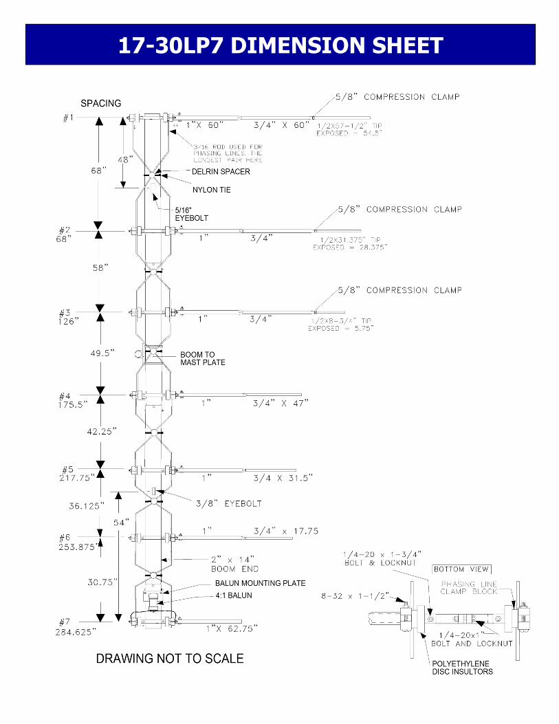
17-30LP7 DIMENSION SHEET
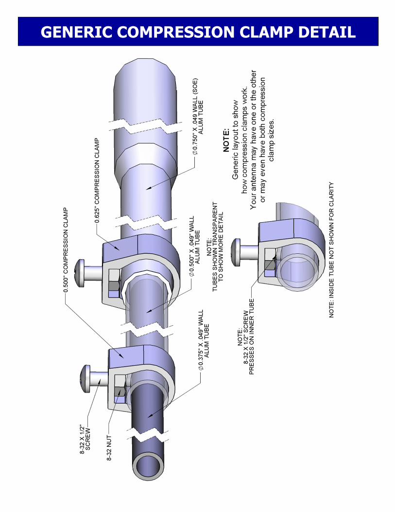
GENERIC COMPRESSION CLAMP DETAIL

DESCRIPTION QTY Boom section 2" x .065 x 95 SOE 3 Boom section 2" x .065 x 14" 1 Element section 1 x .058 x 60" SOE 12 Element section 1" x .058 x 62-3/4" 2 Element section 3/4 x .049 x 60" SOE 6 Element tip, 3/4 x .049 x see DIM. sheet 6 Element tip, 1/2 x .049 x see DIM. sheet 6 Rod insulator, 7/8" x 29.75" fiberglass 3 Rod insulator, 7/8" x 14.75" fiberglass 4 Rod, phasing, 3/16 x 71" aluminum 2 Rod, phasing, 3/16 x 61" aluminum 2 Rod, phasing, 3/16 x 52.5" aluminum 2 Rod, phasing, 3/16 x 45.25" aluminum 2 Rod, phasing, 3/16 x 39" aluminum 2 Rod, phasing, 3/16 x 34" aluminum 2 Boom to mast plate, 6 x 8 x 1/4" aluminum punched 1 Balun, 4:1 ferrite 5 Kw, standard 1 Ring clamp, 2" machined, 7 Element clamp blocks, 3/8" x 1-1/4" x 2-3/16" alum. 14 Rod clamp block 1/4 x 3/4 x 1-1/4" alum. machined 14 Disc insulator,3/8" x 2" polyethylene, machined 7/8" hole 14 Spacer standoff, 3/4 x 2-1/4" Delrin 6 Turnbuckle plate, 2 x 5 x 3/16" aluminum punched 1 Eyebolts, 5/16" 2 Turnbuckle, 5/16" hook and eye 2 Balun mounting plate, 2" x 4-1/4" x 1/8" alum. 1 Support line, 5/16" dacron, 16 foot 1 U-bolt, 2" with cradle 8 U-bolt, 2-1/2" with cradle 1 Compression Clamp, 5/8” 6 Nylon ties, large, 14.5" black 9 Zinc paste (Penetrox, Noalox or equivalent) 1 ounce 1 IN HARDWARE BAGS: Nut, 5/16-18 stainless 16 Lockwasher, 5/16" split ring stainless 16 Bolt, 1/4-20 x 2-1/2" stainless 6 Bolt, 1/4-20 x 1-3/4" stainless 14 Bolt, 1/4-20 x 1-1/2" stainless 14 Bolt, 1/4-20 x 1" stainless 7 Screw, 1/4-20 x 1" stainless, countersunk flathead 14 Nut, 1/4-20 locking, stainless 55 Screw, 8-32 x 1-1/2 14 Screw, 8-32 x 1-1/4 24 Screw, 8-32 x 1/2" 6 Nut, 8-32, stainless 6 Nut, 8-32 locking, stainless 38
M2 Antenna systems Inc. 4402 N. Selland Ave.
Fresno, CA 93722 (559) 432-8873 FAX (559) 432-3059
www.m2inc.com
17-30LP7 PARTS & HARDWARE
Related Documents