M151 Mutt Manual TM_9-2320-218-20sept71
Oct 31, 2015
M151 Mutt Manual TM_9-2320-218-20
Welcome message from author
This document is posted to help you gain knowledge. Please leave a comment to let me know what you think about it! Share it to your friends and learn new things together.
Transcript


G: VII.
VIII. IX.
X.
CHAPTER 4. Srction I.
II.
APPENDIX A.
B.
C.
. I)c*cpwet(v fcmlmg kit ................................... I tltl-;tn1lwrv eltvrnetcw kit ...............................
ItlO-:lnlpcw Onttwy cllarping systcw ..................... hl I6 ,/ I4 riJlc nlqmn: kit ............................... I)ocv and rijc mrtain kit ..............................
514 gun n1o11nt l’cd’.sl”l ................................
.\I)11 I\ Is’l’l~~\‘l’l\ 1.: S’l’OII,\GI~
ShilmcGt and storagct .................................. lhtriwti~m ad nlatcrid ttr lm*vcnI cnwn\- we .............
I~EFJ3tENcES ... ........ .................. .......
MAIN’JT;RIANCE ALLOCA’J‘ION CHART ..............
J)EI’I{OCESSJKG OF VEHICLES ......................
........... ........... ........... ........... ........... ...........
Paragraph Pyle
3.3i-3-4.5 3-22 3-46-3-56 3-26 3-5i-3-58 3.37 .340-3-64 3-05-3-66
3$ 3-42
3.Oi. 3-68 3-42
.............. 4-J-4-4 4-1
............ 4-3-4-i 4-o
. . . A-l-A-4 A-l
H-J. B-2 B-J
. C-I-C-3 C-l
ii


CHAPTER 1
INTRODUCTION
Section I.
l-l. Scope
a. This technical manual contains instructions for organizational maintenance of the 1 / 4 Ton, 4x4, Utility Trucks, M151, M151Al and M151A2; 1/ 4 Ton, 4x4, Utility Truck (with 106 MM Rocoilless Rifle) M151AlC, M825 and the Ambulance Truck M718 and M718Al. The MlSlAlC and M825 vehicles monnts a 106 MM recoilless rifle. The M718 and M718Al vehicles are used as a front line ambulance. The M151AlC and M825 models are basically similar in design to the M151, M151Al and M151A2 vehicles. At- taching parts are added to the M151AlC and M825 making them a mobile weaponry unit and to the M718 and M718Al making them an am- bulance unit. It also provides instructions for organizational maintenance for the M 15 1, M151Al and M151A2 when equipped with any of the following special purpose kits; Deep water fording, 100 ampere alternator, hot water heater (-25 O F.), winterization kit i-65’ F.1, hardtop kit, machine gun mount kit, Ml6 /Ml4 rifle mount kit, door and side curtain kit. The M718 and M718Al can be equipped with 100 am- pere alternator, hot water heater l-25’ F.1 and deep water fording kits.
b. Chapter 3 contains material used in con- junction with major items, contains instructions for organizational maintenance on the vehicle special purpose kits.
c. Appendix A contains a list of current references, including supply manuals, technical manuals, forms, and other available publications for the above vehicles and their related special purpose kits.
d. Appendix B contains the maintenance allocation chart which lists the maintenance responsibilities allocated to each level of main- tenance.
e. TM 9-2320-218-20P contains the repair parts and special tool lists for maintaining the material, and is the authority for requisitioning replacements.
f. This manual differs from TM 9-2320-218-20, August 1968 as follows:
( 1) Revised information on organizational preventive maintenance services.
(21 Revised information on electrical
GENERAL
troubleshooting and service and maintenance instructions on current vehicle produc.tion models.
1-2. Forms and Records
a. Authorized Forms. Maintenance forms and records that are required for use are explained in TM 38-750.
b. Field Report. of Accidents. (1) Injury to personnel or damage to
material. The reports necessary to comply with the requirements of the Army safety program are prescribed in detail in AR 385-40. These reports are required whenever accidents involving injury to personnel or damage to materiel occur.
(2) Ammunition. Whenever an accident or malfunction involving the use of ammunition occurs, firing of the lot which malfunctions will be immediately discontinued. In addition to any applicable reports required in (1) above, details of the accident or malfunction will be reported as prescribed in ‘AR 700-l 300-8.
1-3. Reporting of Errors
Report or errors, omissions, and recommendations for improving this publication by the individual user is encouraged. Reports should be submitted on DA Form 2028 (Recommended Changes to Publications) and forwarded direct to Com- manding General, U. S. Army Tank Automotive Command, ATTN : AMSTA-MAPT, Warren, Mich., 48090.
l-4. Equipment Serviceability Criteria
Equipment serviceability criteria for the vehicles are found in TM 9-2320-218-ESC.
l-5. Administrative Storage
Refer to TM 740-90-l for administrative storage of equipment. Those requirements peculiar to M I5 1 series vehicles are contained in Chapter 4 of this manual.
1-6. Destruction of Army Materiel to Prevent Enemy Use
a.‘The destruction of army materiel to prevent enemy use is a command decision, implemented only on the authority of the Division Commander or a higher commander.
b. Instructions for destruction of the vehicles covered in this manual are contained in chapter 4.
l-1

Section II. DESCRIPTION AND DATA
1-7.
a.
Description of Vehicles (figs. 1-l through l-3)
The ‘/4 Ton, 4x4 Utility Trucks, Ml51 Models (fig. l-l), MlSlAlC and M825, 106 MM Recoilless Rifle (Fig. l-21, and the M718 and M7 18Al Front Line Ambulance Truck (fig. l-3) are designed for use over all types of roads as well as crosscountry terrain, and in all weather con- ditions. While intended operations of the vehicles vary, as do some of their driving characteristics, maintenance support will be the same as for the M 151 series trucks unless otherwise indicated. The vehicles have four driving wheels. Front wheel drive may be engaged as road conditions and terrain conditions require. The vehicles are powered by a four-cylinder, in-line, liquid-cooled, gasoline engine located forward of the passenger compartment under the hood. Vehicles have four- wheel hydraulic service brakes and a mechanical hand brake operates with a contracting band on the transmission-transfer brakedrum. All wheels are individually suspended on coil springs. The body is of unitized construction, and proper precautions should be exercised in raising the vehicle. Lifting
eyes are provided at the wheels and pintle hooks are provided at the rear of vehicles.
b. The Ml51, MlSlAl and MlSlA2, l/ 4 Ton, 4x4, Utility Truck (fig. 1-l) is a general purpose personnel or cargo carrier. Including the driver, it provides space for four men with equipment. Its performance features are con- densed, summarized, and tabulated in paragraph l- 8.
c. The MlSlAlC and M825 vehicles (fig. l-21 are equipped with a 106 MM recoilless rifle on an M79 Rifle Mount. Provisions are provided for carrying six rounds of ammunition and weapon tools to create a mobile weapon system.
d. The M718 and M718A1, 4x4, l/4 Ton, Front Line Ambulance Truck, (fig. l-3) is designed to carry ambulatory and litter patients. The cargo area of the M718 and M718Al is 18 inches longer than the Ml51, MlSlAl and MlSlA2 vehicles and the top 5.3 inches higher to accomodate litters.
1-8. Tabulated Data
The tabulated data you will need to know is contained in table l-l for the proper operation of the Ml51 series vehicles.
AT24 144
l-2

46
b‘ipuw l-2. Utility truck. 4x4. I / 4 ion. with 106 MM recoilless rifle: right rear ciew.

Figure l-4. Location of name. caution andinstructionplates on M151. M151Al. M15lA2. M718 and,M’718Al vehicles.
1-4

l-5

h’igurc Id. Decal OR driving speeds.
Table 1-l. Tabulated Data
DATA Ml51 MElAl M151A2 MlSlAlC M825 M718 M718Al
(al i&lax. Permissible Road Speeds:
1st Gear
2d Gear
3d Gear
4th Gear
Reverse
(bl Fuel:
01 1Min. Research
Octane: (17 Gals1 (cl Fuel System:
1. Fuel Filter:
Impregnated in Tank
2. Fuel Filter: in line
and in tank (Saran)
3. Fuel Pump (Elec.1 in
Tank
4. Fwl l’ynp I Mech. 1 Mounted to Engine
(d 1 Air Cleaner. Oil Bath : Under Vehicle Hood
Capacity : 2.5 Pints
le I Engine Oil:
I. Capacity-4 Quarts
2. Filter-l Quart
3. Oil. Engine t Above 32 o F.I
4.Oil. Engine (+40° to
- I PF. 1 .i. Oil fi:npine (0’ to -_().j°F.I
cf 1 IIifferrntial:
1. Capacity-2 Pint
2. Oil. Gear (Above 32’F.1
3. Oil. Gear t +40° to -1O’F.I
4. Oil. Gear (0’ to -0.5’F.l
(p) Grease:
Type: GAA (11 I Cooling Svstem :
1. Caiacity-0.0 Quarts
2. Belts. Drive:
Generator-_‘.? amp.
Generator-00 amp.
Generator- 100 amp.
Type: “V” Wedge
Width : Gen. 2.5 ‘amp.
Gen. 00-100 amp.
Length: Gen. 2.5 amp.
Gen. 00-100 amp.
3. Fan:
Tvpe-4 Blade
1);ameter: 1.5.0 inch
11 mph 11 mph 11 mph 11 mph 11 mph 11 mph 11 mph
21 mph 21 mph 21 mph 21 mph 21 mph 21 mph 21 mph
40 mph 40 mph 40 mph 40 mph 40 mph 40 mph 40 mph
65 mph 65 mph 65 mph 50 mph 50 mph 65 mph 65 mph
9 mph 9 mph 9 mph 9 mph 9 mph 9 mph 9 mph
Y * 0 * Y * +
b 8
b
*
b
b
*
w
OE30
OElO
OES
G*o9O
GO90
GOS
*
*
oyE30
OElO
OES OES OES
+
GO00 GO00
GOS
GYOOO
GO90
GOS
G*o90
GO90
GOS
r
*
OE30
OElO
OES
Gy090
GO90 GOS
*
0130
OElO
OES
*
GO90
GO90
GOS
*
o*E30
OElO
OES
*
GO90
GO90
GOS
b .r. .Y. Y
* * *
0.
* *
2
3
3
3
3
2
3
3
3
3
2
3
3
3
3
0.38in.
0.47in. 33.08in.
35.2.5in.
0.38in.
0.47in.
33.80in.
35 .‘.iin.
*
*
0.47in.
3.i.2.Sin.
*
*
0.38in.
0.47in.
33.80in. 35.25in.
0.47in.
35.25in.
+
*
0.38in.
0.47in.
33.80in.
35.25in.
0.47in.
35.25in.
*
.Y.
1-6

Table l-1. Tabulated data-Continued
DATA Ml51 MlSlAl M151A!2 MlSlAlC ME25 M718 M718Al
4. Radiator:
Type-Plate. Fin. & Tube Capacity-B.0 Quart Radiator Cap-Pressure Pressure-7.0 psi Thermostat-Spring Cartridge Location-Cyl. Head 180*
F &O Opening Temp. 202*F.
1. Pump. Water:
Type: Centrifical Location-Frt. of Cyl. Bik.
(il Tires:
1. N umber--.S
2. TypeNylon Cord 3. Tread-Non-Directhal 4. Size: 7.00 s 10
.5. Plies: 4. (0 Ply Rating) CjI Tire Inflation l’res.
1 . Fran t : Highway Use:
Cross-Country Use Snow. Sand. 1Mnd
2. Rear Tires:
Highway Use Cross-Country Use Snow. Sand. IMud
Ik I Electrical System: I. Batteries-_’ HN 2. VoltapP-12 3. Plates Per Cell -11 4. Negative Ground - ,. .,. I ype-Water Proof 0. Number Used-2 7. Series-24 Volts 8. Amp. Hr. Cap. 4.5 at 20 Hr 0. Spark Plug:
IO. Gap-O.20 - 0.32” III Generator: 2.i amp.
1. Model : GHA480SUT 2. Part No. 7.524310 3. FSN 2020-;3;-4730 4. Rating:
Volts-24 Amperes-25
.5. Oper. Range-1 i30-8000
rpm 0. Type: Shunt Field 7. No. Brushes 8. Rotation-Clockwise
From IIrive F;nd 0. Control of &lax. Output
Voltage Reg. Im 1 Generator: 23 amp.
1. IModel-GHA4804 JUT 2. I’art No. llJO.~O808 3. FSN 20’0-OO?,-0.?43
4. Rating: Volts--“4
Amperes--_‘., .5. Oper. Range-l 760-8000
rpm 0. Type-Shunt Field 7. No. Brushes-2
*
*
a
*
3
Y
Y
Y
3(
Y
0
e
* * F
*
+
*
F
.v
*
20 Ibs. 20 Ibs. 20. Ibs. 25 Ibs. 25 Ibs. 20 lbs.
20 Ibs. 20 Ibs. 20 lbs. 25 lbs. 25 lbs. 20 lbs.
1.5 Ibs. 15 Ibs. 15 lbs. 20 lbs. 20 lbs. 15 lbs.
25 tbs. 25 Ibs. 25 Ibs. 40 Ibs. 40 Ibs. 25 Ibs.
20 Ibs. 20 Ibs. 20 Ibs. 40 Ibs. 40 Ibs. 20 lbs. 15 Ibs. 15 Ibs. 15 Ibs. 35 lbs. 35 Ibs. 20 lbs.
* * * e * + .$ *
14mm *
Y *
Y * * 0 * +
14mm *
* * * *
* e Y
*
14mm +
20 Ibs.
20 lbs. 15 lb%
25 Ibs. 20 Ibs. 20 lbs.
Y Y * 0 * * .$ *
14mm *
l-7

DATA ---
8. Rotation-Clock-vise from
Drive End
9. Control of Max. Output-
Voltage Reg.
II I Generator-60 amp.
1. Model-3002-AA
2. Part No. 10929868
3. FSN 2920-909-2483
4. Rating
Volts-28
Amperes-60
.5. Oper. Range-2000-8000
rpm 6. Type: Internal Rectifaction 7. No. Brushes-Internal
Regulation
to l Service Brakes : 1. Type-Hydraulic 2. Brake Fluid-l Pint
Master Cylinder Located
Cowl Left Side
Ipl Parking Brake:
Type-Mech. Drum & Band
((11 l’ayload: Including Personnel- 1. Highway
2. Cross Country
Rated Payload : 3. Front Axle Wt. -Empty
-Loaded
-Cross Country
--Highway
4. Rear Axle Wt.
Empty
Loaded
Cross Countrv
Highway
.5. Gross Vehicle Wt.
Highwav
Shipping
lrl Engine:
I. General Arm)- Design
4 Cyl. Int. Combustion
Horse Power Rating
71 HP at 4000 rpm at OOoF. Air Temp-Torque
1% lb. ft. at 1800 rpm
B ore: 3.875 inch
Stroke: 3.00 inch
I)ispl: 141..5 cu. inch
Cylinders: 4
Firing Order l-3-4-2
2. Valve Arrangement:
Overhead
:I. Valve Clearance:
Intake: 0.0 15 inch
lishaust: 0.0 1.3 inch Camp. Ratio: - - i ..o-1
Camp. at Cranking: 13.5-14.5 psig
t theoretical I
Table I-I. Tabulated data-Continued
Ml51
y:
3
x.
*
1200 Ibs.
800 Ibs.
1310 Ibs.
149.5 Ibs.
1.530 Ibs.
1040 Ibs.
1655 lbs.
2020 Ibs.
3.550 lbs.
2280 Ibs.
M151Al
*
*
b
+
1200 Ibs.
800 Ibs.
1310 lbs.
1495 lbs.
1530 Ibs.
1040 lbs.
1655 Ibs.
2020 Ibs.
3550 Ibs.
2280 Ibs.
Ml%42
e
+
x.
*
1200 lbs.
800 Ibs.
Incl.
1365 Ibs.
1530 lbs.
156.5 Ibs.
107.5 Ibs.
1710 Ibs.
207.5 lbs.
3640 lbs.
2370 Ibs.
MlSlAlC
* .Y.
*
1730 lbs.
1130 Ibs.
106 MM Rifle
*
b
0
730 lbs.
130 lbs.
1390 lbs.
1560 lbs.
1110 lbs.
26i0 lbs.
4230 lbs.
2990 Ibs.
W / Rifle
2500 lbs.
W / Equip
No Rifle
445 lbs.
620 lbs.
145 lbs.
:?OO lbs.
230 lbs.
080 Ibs.
.F / Rifle
!590 Ibs.
K’ / Equip \Jo Rifle
M?18
F
.Y
+
* \
9
900 lbs.
900 lbs.
,320 lbs.
,390 Ibs.
340 lbs.
! 170 lbs.
,560 lbs.
l525 lbs.
5718A1
900 lbs.
900 lbs.
1370 lbs.
1440 lbs.
1380 Ibs.
22 10 lbs.
3650 Ibs.
2615 lbs.
l-8

Table 1-I. Tabulated Data-Continued.
DATA
4. Carburetor:
Type: Single Barrel
lMake : Zenith or Halley
Choke : Manual
5. D. C. Generator-Reeulator
Make-l’restolite
Current Limit-28.3
700 F.
6. Starter 1Motor
Make : I’restolite
Optional: Delco-Remy
Type: Series Wound
Voltage: 24 DC
Drive-Follow-Through
(Over Running Clutch 1 Starting Motor Switch
IOn Toe Board Below
Clutch Pedal
7. Weight:
Power Plant-528 lb
Engine with Flywheel
Accessories-328 Ibs.
Engine with Flywheel
W / 0 Accessories-257
Belts for Fan. 25 amp Generator and Water
Pump-2 “V” Wedge,
0.38 Inch Wide X 33.0
Inch Long
at
and
and
Ibs.
Belts for Fan 60 amp Al-
ternator 3 “V” Wedge
0.47 In. Wide X 35.25
In. Long
Windshield Washer Heservoil
Cap. 3 Qts. (s I J)imensions:
Length
Widtll
To Top lklost Point
Wheel Base
(t I Personnel Complement:
Crew. Operator and Patients
(u 1 Cruising Range: I W / 0 Towed Load 1
tv 1 Fording Depth W / Out Special
Equipment: (w) Turning Radius:
lxl
lyl
Vehicle-Kits : Winterization (--6.i°F. I Hardtop
IMachine Gun Mount
J)oor & Side Curtain
M IO/ 14 Rifle Mount Ijeep Water Fording
100 amp Alternator
Heater. Hot Water (-_‘.?°F.l
Vehicle Lifting
Overload
Power Train : Clutch Type-Single
Dry Disc.
Diameter-&i Inch
Transmission Type:
Selective Synchromesh
Ml51
F
.s
*
*
132.7 in.
64.0 in.
71.0 in. 85.0 in.
4
300 tn
21.0 in.
17.0 ft.
M151Al
+ *
Y
Y
e
8
132.7 in.
64.0 in.
71.0 in.
85.0 in.
4
300 m
21.0 in.
18.5 ft.
M151A2
9
b
9
*
132.i in.
64.3 in.
71.0 in.
85.0 in.
4
500 m
21.0 in.
18.5 ft.
MlSlAlC
* Y
*
*
z
3
*
143.5 in.
76.5 in.
77.2 in.
85.0 in.
4
275 m
20.0 in.
18.3 ft.
M825
Y
4
143.5 in.
76.5 in. 77.2 in.
85.0 in.
M718
+ *
*
Y
*
Y
*
143.0 in.
72.0 in.
76.3 in.
85.0 in.
M7lSAl
.r.
b
143.0 in.
71.6 in.
76.3 in.
85.0 in.
4 Refer to TM 9-2320-218-10
275 m
20.0 in.
18.5 ft.
300 m
21.0 in.
18.5 ft.
300 m
21.0 in.
18.5 ft.
l-9

Table l-l. Tabulated Data-Continued
DATA
Speeds-4 Forward 1 Reverse
Synchronized Gears 2d. 3d and 4th
(Lubricant Cap. l51/ Pints)
Gear Ratio: First--T,.? 12-l
Second-3.1 iO-I Third-:.614-l
Fourth--1.000-1
Heverse-i.4Oi-I (n i Transfer-Single Speed: laa I Steering Geometry:
Wheel Toe-in-l / 32-.5 / 32 In. Front Drive Turning Angle for Each Wheel:
Maxinnrm-rigbt-22° -Left-3 lo
Steering Gear Ratio: 16.4-1 Type: Worm & Double Roller
Steering Wheel Size: li.25 in. dia. Type: Three Spoke
lac 1 Propeller Shaft: Type of Joint: Cardan Front and Rear Drive
tad I Ilifferential Type: Type : Drive Through
Gear and Type:
Hypoid 4 Pinion I)rive Gear Ratio 4.86-1 Lubrication Capacity-2 Pints
(ae I Suspension : Type: Independent. 4 Wheel Springs: Coil
Front Shock Absorbers:
Type: Hydraulic. Telescopic Action : Two-Way. Direct. (Jounce and Rebound-Control1 Stops: Internal. Hvdraulic-
(Jounce and Rebound1 or Mechanical (Esternal Jounce and Internal Rebound I Rear Shock Absorbers:
Type: Hydraulic Telescopic Action : Two-Way. Direct (Jounce and Rebound Controll Stops: Internal. Hydraulic (Rebound Only or Mechanical1
(Internal Rebound Only1 taf I Ignition :
IXstributor Ass?. (I’restolitel Rotation (Rotor End Clockwise1
Type of Advance: (Centrifugal1 Breaker I’oint Opening:
0.017-0.022 Inch
Cam Angie-30° Voltage-24 , . . 1 Iming--ho RTDC Spark Plug Gap-O.O2o-
0.032 IllCll
Engine Firing Order-l-3-4-2 Ignition Coil Located in
Distributor Housing
l-10
- Ml51 MlSlAlC M716Al
+
b
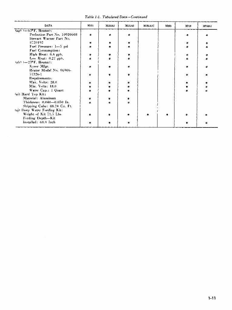
Table I-l. Tabulated Data-Continued
DATA
lap I (-_(3 F. Heater i : Perfection Part No. 10920608
Stewart Warner Part No. 87”01’)2
Fuel 1’ resswe: l-3 psi
Fuel Consumption : High Heat: 0.4 gph.
Low Heat: 0.7; gph.
fall I C-I?.?~E’. Heater I : Kysor Mfg.
Heater 1Moclel No. 06006-
.i13”0-1
Rqttirements: Max. Volts: 28.0
Min. Volta: 18.0
Water Cap.: 1 Quart (ail Hard Top Kit:
Material: Alllminum Thickness: 0.040--O.O.iO In.
Shipping Cube: 88.24 Cu. Ft.
!a.;, Ih=ep Water Fording Kit:
Weight of Kit il..5 Lbs
Fording IIepth-Kit
Installed: 00.0 Inch
Ml51 M151Al M151.U MlllAlC
-
M825 M718A1
l-11

CHAPTER 2
SERVICE AND MAINTENANCE INSTRUCTIONS
Section I. SERVICE UPON RECEIPT OF MATERIEL
2-1. General
Refer to TM 9-2320-218-10 for operating in- structions, break-in operating cautions, and break- in speeds.
2-2. Equipment Log Book (Binder)
The Equipment Log Book will be with the item to which it pertains when the equipment is serviced, repaired, modified, or transferred. Instructions for preparation and application of equipment log books are contained in TM 38-750. Also, special reporting requirements on performed maintenance on the equipment are contained in TM 38-750.
2-3. General Preliminary Services
(Performed by Organizational Maintenance or Supplying Organization)
a. If any exterior surfaces are coated with rust- preventive compound, remove it with dry-cleaning solvent or mineral spirits paint thinner.
b. Read Processing Record for Shipment and Storage of Vehicles and Unboxed Engines tag (DD Form 1397 1 and follow all precautions checked thereon. This tag should be attached to the steering wheel, shifting levers, or ignition switch.
c. Crank engine at least two revolutions, before turning ignition on, to test for hydrostatic lock. (This precaution is taken because there might be an excess of preservative oil in the combustion chambers, or, possibly, coolant may have leaked into them 1.
NOTE If the material has been driven to the using organization, most or all of the foregoing procedures should have been performed.
d. On processed material, when engine has been
stored for over 30 days, service engine as outlined in TB ORD 392.
e. Follow the general procedures given in TM 9- 2320-218-10.
NOTE Seat belt anchors are provided on M 15 lA2 models. It is the responsibility of local commanders to decide whether or not seat belts are to be installed to Ml5 IA2 or other M 15 1 series vehicles when used for administrative purposes.
2-4. Specific Preliminary Services
a. Perform the “S” (h-month or 6000 mile) preventive-maintenance services. Refer to paragraph 2-16 for specific procedures.
b. Lubricate vehicle in accordance with lubrication order regardless of/interval, excluding gearcases and engine. Check processing tag for gearcases and engine oil, If tag states that oil is suitable for operation and is of the proper viscosity for local climatic operation, check the level, but do not change the oil.
c. Schedule second “S” service on DD Form 3 14, Preventive-Maintenance Roster, and arrange for oil change at suggested normal intervals (Rkfer to LO 9-2320-218-121.
2-5. Correction of Deficiencies
a. Ordinary deficiencies disclosed during preliminary inspection and servicing, or during break-in period, will be corrected by the using organization or a higher category of maintenance.
b. Serious deficiencies, which appear to involve unsatisfactory design or material, will be reported in accordance with instructions in paragraph 1-3.
Section I I. PARTS, TOOLS, AND EQUIPMENT
2-6. General
Tools, equipment. and repair parts are issued to organizational-maintenance personnel for main- taining the materiel. Tools and equipment should not be used for purposes other than prescribed and. when not in use. should be properly stowed in the chest and / or roll provided for them.
2-7. Repair Parts
Repair parts are supplied to organizational
maintenance for replacement of those parts most likely to become worn. broken, or otherwise un- serviceable. provided replacement of these parts is within their scope. Organizational repair parts supplied for the 1 / 4 ton utility truck, M 15 1 series and M 718 ambulance vehicles are listed in TM 9- 3320-2 18-20P which is the authority for requisitioning replacements.
2-l

2-8. Common Tools and Equipment Certain tools and equipment specially designed for
Standard and commonly used tools and equipment organizational maintenance, repair, and general
having general application to this material are ,use with the materiel are listed in table 2-1 for
authorizeh for issue by tables of allowances and information only. This list is not to be used for
tables of organization and equipment. requisitioning replacements. Special tools for
2-9. Special Tools and Equipment organizational maintenance are listed in TM 9-
(fig. 2-l) 2320-22%20P which is the authority for requisitioning replacements.
I~igrrw 2-I. Special tools and equipment for organizational maintenance.
Table 2-l. Special Tools and Equipment for Organizational Maintenance
Item
1 Puller
2 Replacer
3 l’uller
Identifying No.
.i 120-507-6223 (7Oi6223)
3120-795-01.52 li950152)
51%6X-i161 (73452341
References Fig. Par.
2-35i 2-165
2-307 2-136 2-3’1 2-142 z-310 Z-141
Section III. LUBRICATION
Use
Removing steering wheel
Instailing differential side gear flange seal and retainer.
Installing front and rear wheel-bearing seals. Removing outer wheel bearing.
2-10. Lubrication Order
The lubrication order prescribes cleaning and lubricating procedures as to locations, intervals, and proper materials for these vehicles. Lubrication to be performed will be in accordance with the lubrication order. Whenever necessary, the operator, crew, or user will assist the organizational-maintenance personnel in lub- rication of the materiel.
2-2
2-11. General Lubrication Instructions
a. General. Any special lubricating instructions required for specific mechanisms or ‘parts are covered in the pertinent section.
b. Service Intervals. Service intervals specified on the lubrication order are for normal operation and where moderate temperature, humidity, and atmospheric conditions prevail.

c. Reports and Records. (1) Report unsatisfactory performance of
preserving materials in accordance with in- structions in paragraph 1-3.
(2 1 Maintain a record of lubrication of the
materiel on Form 2408-1, Equipment Lubrication Record.
2-12. Painting
Instructions for camouflage painting are contained in FM 5-20.
Section IV. PREVENTIVE-MAINTENANCE SERVICES
2-13. General
To insure that the vehicle is ready for operation at all times, it must be inspected systematically so that defects may be discovered and corrected before they result in serious damage or failure. The necessary preventive-maintenance checks and services to be performed are listed as described in table 2-2.
2-14. General Procedures
a. Automatically Applied. All of the general procedures given in the operator’s manual will be followed. Organizational mechanics must be so thoroughly trained in these procedures that they apply them automatically at all times in the per- formance of their duties.
b. Driver or Crew Participation. The driver or crew usually accompanies the materiel and assists the organizational mechanic in the performance of his services.
c. Unwashed Materiel. The driver or crew should present the materiel for a scheduled preventive-maintenance service in’ a reasonably clean condition; that is, it should be dry and not caked with mud to such an extent as to seriously hamper inspection and services. However, washing of the materiel should be avoided immediately prior to an inspection, since certain types of defects such as loose parts and oil leaks may not be evident immediately after washing.
d. Services. Organizational maintenance serv- ices are defined by, and restricted to, the following general procedures unless approval has been given by the supporting maintenance organization.
(1) Adjust. Make all necessary adjustments in accordance with instructions contained in the pertinent section of this technical manual or technical bulletins.
(21 Clean. Clean the unit to remove old lubricant, dirt and other foreign material.
(3 1 Special Lubrication. This applies either to lubrication operations that do not appear on the lubrication order or to items that do appear but which should be performed in connection with the maintenance operations.
NOTE In order to lubricate “U” joint grease
fittings that are hard to get at, a special grease gun adapter must be used. This adapter is an authorized item in the lubrication kit FSN 4930-357-6301, and also available separately under FSN 4930- 204-2550. (4) Service. This usually consists of per-
forming special operations, such as replenishing battery water, draining and refilling units with oil, and changing or cleaning the oil filter, air cleaner, or cartridges.
(5) Tighten. All tightening operations should be performed with sufficient wrench torque (force on the wrench handle) to tighten the unit according to good mechanical practice. Use a torque- indicating wrench where specified. Also do not overtighten, as this may strip threads or cause distortion. Tightening will always be understood to include the correct installation of lockwashers, locknuts, locking wire, or cotter pins to secure the tightened nut. Torque specifications for attaching parts are included with the paragraph containing
‘the maintenance procedure. (6) Modification Work Order Application. At
least every 6 months, a checkup will be made to see that all applicable modification work orders published in DA Pam 310-7 have been ac- complished. Also refer to DA Form 2408-j (Equipment Modification Record). If a field maintenance modification has not been applied, promptly notify the supporting maintenance of- ficer. No alteration or modification, which will affect moving parts, will be made by organizational personnel, except as authorized by official publications.
e. Special Conditions. When conditions make it difficult to perform the complete preventive- maintenance procedures at one time, they can be handled in sections. Plan to complete all operations within a week if possible. All available time at halts and during bivouac must be utilized to assure that maintenance operations are completed.
f. DA Form 2404, Equipment Inspection and Maintenance Worksheet. Perform the “S”
preventive-maintenance service in the sequence shown in table 2-2, using DA Form 2404 as a worksheet.
2-3

Z-15; SenGannual ‘73” Preventive-Maintenance 2-16. Specific Procedures for Organizational Services Maintenance
a. Purpose. The “S” preventive-maintenance services insure the correct adjustment, securing, and assembly of all components of the materiel. Necessary replacements, cleaning, lubrication, and protection of parts and/ or assemblies will be accomplished as required, to give reasonable assurance of trouble-free operation until the next “S” preventive-maintenance service is performed.
b. Intervals. The semiannual “S” preventive- maintenance services are performed by the organizational mechanics every six months or at every 6000 miles of vehicle operation, whichever occurs first.
Specific procedures for performing each item in the semiannual “S” preventive-maintenance services on materiel are outlined in table 2-3. Result of inspection and checking during preventive- maintenance services is authorization to take corrective action to remove the trouble fo’und, by performing the service or repair at organizational- maintenance level. If repairs by a higher category of maintenance are required, a DA Form 2407, Maintenance Request, will be prepared and for- warded with the equipment to the supporting maintenance activity.
1 Cooling system 7 Starter and switch 12 Steering system 1; Clutch 2 Oil filter (engine right side1 8 Instruments 13 I’ropeller allaft and “U” joints 1X Transfer 3 Engine performance 0 Transmission 14 Shock absorbers !O Service brake system 4 Ignition svsteni IO Batteries 1.5 Suspension 20 Generator and wiring 5 Fuel system 1 I I’arking brake 10 Bfdy w / frame and accessories ’ 21 Air intake system 0 Choke and throttle linkage 22 Fan and generator belts
I.‘ipurc 2-2. Prmenthe-maintenance locator.
2-4

Table 2-2. Preventive-Maintenance Checks anh Services
Cooling System
2 Air Intake System
3 Ignition System
4 Exhaust System
5 Fan and Generator Belts
6 Generator and Wiring
7 Linkage and Lines
8
9
Oil Fper
Fuel System
10
11
Batteries
Starter and Switch
Organizational
Item to be inspected
-
I Procadurea
Inspect radiator core, hoses, cap and gaskets. Check core for clogging or bent fins. Observe coolant level. If required. drain radiator and cylinder block, flush radiator and cylinder block, flush and refill cooling system and add rust inhibitor, unless antifreeze containing rust inhibitor, is used. In cold weather, test antifreeze. Add as required.
Check air cleaner, air cleaner and air intake hose for secureness. Inspect hose for damage. Check air cleaner element for contamination and clean if necessary. Inspect for proper oil level.
If engine performance is satisfactory and shows no excessive loss of power. misfire, or exhaust smoke. only a visual inspection of the ignition system will be made. If loss of power, misfire, or excessive exhaust smoke is noted, isolate the difficulty by troubleshooting.
NOTE Spark plugs. ignition, points, and capacitor must be replaced after 12,000 miles of service.
Listen for loud or unusual noises and look for exhaust leaks. Tighten exhaust manifold mountings if required. Inspect muffier and exhaust pipe for damage.
Inspect pulleys and fan for alinement. Check belts for proper tension. Notice if water pump is leaking.
Check wiring for loose connections or worn insulation. Check security of generator mounting.
Inspect carburetor. choke. and throttle linkage ind lines. Observe if choke and throttle valves open fully. Make an engine vacuum test and adjust carburetor mixture. Test fuel pump pressure. Examine fuel lines and connections for evidence of leaks. Examine ventilation lines for loose connections. Clean and inspect .the ventilation control valve every 12,000 miles or annually which ever comes. first. Chick condition of oil., If oil change is necessary. change oil and replace oil filter.
Inspect engine compartment and under vehicle for leaks. Check lines and connections for damage. Replace in-line fuel filter every 12,000 miles or annually which ever comes first IMI.SlA2. M825 and Mi18Al only).
Test batteries only after engine has been stopped for five minutes or more. Check. specific gravity of each cell and record specific gravity. Check electrolyte level. Inspect cables and clamps for tightness and condition. After test. clean tops of batteries. coat terminals lightly with grease, and repaint carrier if necessary.
Notice if starter makes unusual noise. Notice if starting motor engages smoothly and turns engine with normal cranking speed.
Semiannual schedule
Paragraph reference
2-63
2-43
2-l 9
2-40
2-66
2-29 2-44 2-49 2-50
2-34
2-52
2-20 2-25
2-5

Table 2-2. Preventive-Maintenance Checks and Services
Sequence
1.2 Engine Performance
13 Instruments
14 Safety Devices
15 Service Brake System
16 Parking Brake
li Clutch
18 Transmission
19
20
2-6
Transfer
Steering System
Gganizational
1temtobs inspected Procedures
In starting and warming engine, observe if it starts easily and if action of throttle and choke control assemblies is satisfactory. Notice if idling speed is correct. Listen for any unusual noises at idle and higher speeds. When operating vehicle. notice if it has normal power and acceleration in each speed range. Listen for any unusual noises when engine is under load.
Check fuel gage, battery-generator indicator. speedometer. oil pressure gage, temperature gage and ignition switch for normal readings. Notice if ignition switch operates freely. Check other controls for normal operation.
Depress horn button to sound horn and determine if signal is normal Iif tactical situation permits). Test windshield wipers for satisfactory operation. Examine rear view &ror and reflectors. Examine safety strap for secureness. Check fire extinguisher.
NOTE M151A2. M825, and M718Al vehicle have electrical windshield wipers with manually operated washers, two rear view mirrors and adhesive stick-on reflectors. Check these items for proper function.
lMake several stops and check for unusual braking conditions. Check brake pedal for specified free travel. Remove one wheel and tire assembly and drum from each side of the vehicle and inspect brakedrum, brake lining, brakeshoe anchor. hold-down springs, retracting springs, brakeshoe adjusting screw. and wheel cylinder. If brake lining thickness from the outer surface to the rivet head is less than 3 / 64-inch. replace brakeshoe assem- blies. If evidence of oil or grease is found on
brakeshoe assemblies. replace shoe assemblies.
Check to determine if parking brake control lever holds and if the lever requires more than three-quarters travel for full application. Stop vehicle on an incline and apply parking brake to see if it holds the vehicle. Inspect for correct adjustment of lining to drum.
Determine if action of pedal return spring is satisfactory. Note if clutch disengages com- pletely or if it has a tendency to drag. Note if clutch engages smoothly or if it chatters. grabs. or slips. With transmission in neutral. depress clutch and listen for unusual noise which may indicate a defective release bearing. Check clutch pedal free travel. Note operation in all gears. Note ease of shifting. Listen for unusual noises and inspect for signs of malfunction or lubricant leakage.
Note operation of transfer in all output combinations. Check ease of shift. Listen for unusual noises. and inspect for signs of malfunction or lubrication leakage.
Check for binding. Esamine steering column and wheel. Inspect for damaged seals. Inspect to determine that steering stops are properly adjusted.
Paragraph referen-
Z-Ii1 2-l 73
‘-167
1-4 1

Table 2-2. Preventive-Maintenance Checks and Services
zsz 21 Body with Frame
Accessories
22 Lights and Reflectors
23 Towing Pintle
24 Bumpers
25 Suspension
26 Propeller Shafts and “U” Joints
27 Final Road Check
Semiannual schedule
Make general inspection of body including .glass. panels, top. fenders, bows, paulins, curtains, brush guards, hinges, brackets, and fasteners. Inspect seat frames and upholstery.
Examine condition of paint and check markings and name, caution, and iden- tification plates for legibility.
During stops in the road test, check operation
of lights and light switches. Check for damaged reflectors.
Check operation of pintle hook. Check mounting bolt for tightness.
Inspect front and rear bumpers for looseness or damage.
Make certain wheel driveshafts are installed
correctly. Inspect seals for damage. If damaged, inspect wheel bearing grease for dirt. Inspect for worn rubber bushings. Check
upper and lower ball joints for damage (front).
lMake certain suspension arms are not
damaged. Inspect for damaged springs. Check shock absorbers and brackets for damage.
Check for leaks. Inspect rubber insulators for excessive wear.
Inspect for loose bearings, damaged seals. damaged lubricant fittings and bent shafts. Inspect for looseness of bolts and tighten as
required.
Perform final road test. Pay special attention to items which have been repaired or adjusted.
Paraara&
2-198
Z-141
2-142
“-148
2-127
2-128
2-7

Section V. TROUBLESHOOTING THE VEHICLE
2-17. Scope
a. This section contains troubleshooting in- formation and tests for locating and correcting some of the troubles which may develop in the vehicle. Each symptom of trouble or malfunction given for an individual unit or system is followed by a list of probable causes of the trouble and corrective ac- tions necessary to remedy the malfunction.
b. This technical manual cannot cover all possible troubles and deficiencies that may occur under the many conditions of operation. If a specific malfunction, probable cause, and corrective action, therefore, is not covered herein proceed to isolate the system in which the trouble occurs and then locate the defective component. Use all the senses to observe and locate troubles. Do not neglect use of any test instruments such as an ohmmeter, voltmeter, ammeter, test lamp, hydrometer, and pressure and vacuum gages that are available. Standard automotive theories and
principles of operation apply in troubleshooting this vehicle. Question the drive to obtain maximum number of observed malfunctions. The greater the number of malfunctions that can be evaluated, the easier will be the isolation of the defect.
c. The tests and remedies provided in this section and governed by the scope of the organizational level of maintenance.
2-18. Procedures
a. Table 2-3 lists possible malfunctions that may occur in the vehicle or in individual units or systems of the vehicle. Each malfunction is followed by a list of probable causes that must be considered in determining corrective action.
6. Where electrical malfunctions occur, only correction of minor and obvious causes, such ‘as frayed cables or loose connections, are listed in table 2-3. All other electrical malfunctions are covered fully in the Electrical Troubleshooting charts, paragraphs 2-19 throllgh 2-25.
Table 2-.?. Troubleshooting
Malfunction
1. Engine fails to crank or cranks SlOwly.
2. Engine cracks but fails to start
3. Engine starts but fails to keep running.
Probable Cause Corrective Action
ENGINE n. Defective starter system. 0. IMechanical seizure of parts.
c. Incorrect oil viscosity (cold weather only).
a. Troubleshoot starting system. b. Notify support maintenance.
c. Inspect engine oil. Drain and fill
with correct grade as specified in lubrication order.
tl. Faulty batteries or cables. rl. Check for loosened cables of
connectors at battery. battery to frame connection. starter switch, starter terminal stud or the
engine to frame cable. Very often a poor connection in this high current circuit can be detected by feeling each connection for heat while the starter is energized.
a. If choke has been used excessively, fuel may flood the combustion chamber causing engine not to start. Push choke all the way in.
open throttle and crank engine to clean out excessive fuel. If flooding continues. check fuel
system. (items 1.5 through Igl. h. Troubleshoot ignition system.
c. Test fuel pump pressure tpara 2-49 or Z-50 I.
;I. Combustion chambers flooded with fuel.
(1. Current not reaching spark plug. f’. Inoperative fuel system.
rl. Incorrect ignition timing.
il. Engine idle speed set too low.
1). l)efective fuel pump.
c. Choke not operating properly.
tl. Ilefective carburetor.
tl. Adjust ignition timing lpara 2- 711.
il. Adjust idle speed lpara 2-44 and 1-4.5 I.
6. Check fuel pump pressure tpara 2- 40 or Z-301.
c. Check choke linkage and correct
any binding condition or replace
damaged linkage tpara 2-4iI. tl. Heplace carburetor (para 2-44
and 2-43 I.
2-8
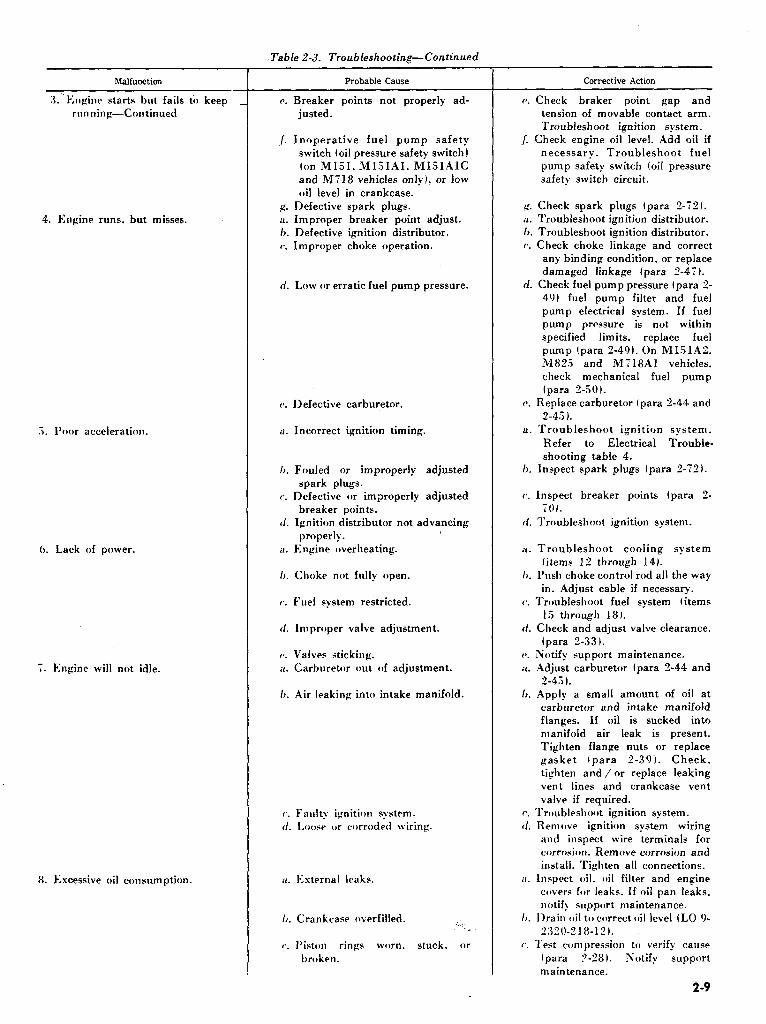
Table 2-3. Troubleshooting-Continued
Malfunction
:l.‘k:nginr starts but fails to keep rlln~iinp-Colltinued
4. Engine runs, but misses.
5. Poor acceleration.
0. Lack of power.
i. Engine will not idle.
8. Excessive oil consumption.
.._ c. Breaker pomts not properly ad-
,/. Inoperative fuel pump safety switch toil pressure safety switch I ton lM151. M151AI. MI5lAIC and MY18 vehicles only). or low oil level in crankcase.
p. Defective spark plugs. ii. Improper breaker point adjust. h. Defective ignition distributor. c. Improper choke operation.
ri. Low or erratic fuel pump pressure.
(1. Defective carburetor.
a. Incorrect ignition timing.
/J. Fouled or improperly adjusted spark plugs.
c. Defective or improperly adjusted breaker points.
tl. Ignition distributor not advancing properly.
il. Engine overheating.
I,. Choke not fully open.
(‘. Fuel system restricted.
tl. Improper valve adjustment.
P. Valves sticking. a. Carburetor out of adjustment.
6. Air leaking into intake manifold.
r’. Fanltv ignition system. tl. LOOPC or corroded wiring.
il. l;sternal leaks.
I,. Crankcase overfilled. :..
(‘. Piston rings worn. stuck. or broken.
Corrective Action
(1. Check braker point gap and tension of movable contact arm. Troubleshoot ignition system.
1. Check engine oil level. Add oil if necessary. Troubleshoot fuel pump safety switch toil pressure safety switch circuit.
g. Check spark plugs (para 2-72). a. Troubleshoot ignition distributor. h. Troubleshoot ignition distributor. c. Check choke linkage and correct
any binding condition. or replace damaged linkage tpara 2-47).
d. Check fuel pump pressure (para 2- 491 fuel pump filter and fuel pump electrical system. If fuel pump pressure is not within specified limits. replace fuel pump (para 2-491. On M151A2. lM83.5 and 1M718Al vehicles. check mechanical fuel pump lpara 2-501.
c. Replace carburetor (para 2-44 and 2-4.5 1.
a. Troubleshoot ignition system. Refer to Electrical Trouble- shooting table 4.
h. Inspect spark plugs lpara Z-721.
c. Inspect breaker points (para 2- 701.
rf. Troubleshoot ignition system.
i, . Troubleshoot cooling system (items 12 through 14).
h. l’ush choke control rod all the way in. Adjust cable if necessary.
c. Troubleshoot fuel system (items 1.3 through 181.
I/. Check and adjust valve clearance. tpara “-33 1.
(A. Notify support maintenance. it. Adjust carburetor (para Z-44 and
2-4.5 1. 6. Apply a small amount of oil at
carburetor and intake manifold flanges. If oil is sucked into manifold air leak is present. Tighten flange nuts or replace gasket lpara Z-391. Check. tighten and / or replace leaking vent lines and crankcase vent valve if required.
I’. Troubleshoot ignition system. rl. Remove ignition system wiring
and inspect wire terminals for corrosion. Remove corrosion and install. Tighten all connections.
a. Inspect oil. oil filter and engine covers for leaks. If oil pan leaks. notify sirpport maintenance.
I>. 1)rain oil to correct oil level IL0 9- ‘X0-21%171.
c’. Test compression to verify cause tpara ?-28 I. Notify support maintenance.
2-9
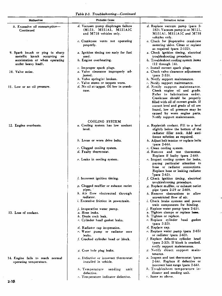
Malfunction
8. Excessive oil consumption-
Continued
9. Spark knock or ping (a sharp
metallic knock occurring on acceleration or when operating
under heavy load).
10. Valve noise.
11. Low or no oil pressure.
12. Engine overheats.
13. Loss of coolant.
14. Engine fails to reach normal operating temperature.
Table 2-3. Troubleshooting-Continued
Probable Cause
n. Vacuum pump diaphragm failure
(Ml51, MlSlAl, MlSlAlC and M718 vehicles only.
c. Crankcase vents not operating
properly.
a. Ignition timing too early for fuel
used. h. Engine overheating.
c. Improper spark plugs. a. Valve clearance improperly ad-
justed. h. Valve spring(s) broken.
c. Valve stems or tappets worn. d. No oil at tappet. Oil low in crank-
case.
COOLING SYSTEM a. Cooling system has low coolant
level.
h. Loose or worn drive belts.
c. Clogged cooling system. d. Faulty thermostat.
c. Leaks in cooling system.
/. Incorrect ignition timing.
,c. Clogged muffler or exhaust outlet pipes. ’
II. Air flow obstructed through radiator.
i. Excessive friction in powertrain.
;. Inoperative water pump. a. Hose leaks. h. Drain cock leak. I’. Cylinder head gasket leaks.
d. Radiator cap inoperative.
c. Water pump or radiator core leaks.
J Cracked cylinder head or block.
p. Core hole plug leaks.
il. 1)efcctive or incorrect thermostat installed in vehicle.
b. Tern perature sending unit
defective. c. Temperature indicator defective.
Corrective Action
d. Replace vacuum pump (para 2- 182). Vacuum pumpis on M1.51. MlSlAl, Ml5lAlC and M718 vehicles only.
B. Check for .
f
operative crankcase metering v lve. Clean or replace
as required’ (para 2-122).
a. Check ignition timing, electrical troubleshooting procedure.
h. Troubleshoot cooling system items (12 through 14).
c. Install correct spark plugs. a. Check valve clearance adjustment
(para 2-33). h. Notify support maintenance. c. Notify support maintenance.
d. Notify support maintenance. Check engine oil and grade. Refer to lubrication order.
Crankcase should be properly filled with oil of correct grade. If
correct level and grade of oil are
found, low oil pressure may be. caused by worn engine parts. Notify support maintenance.
a. Replenish coolant. Fill to a level slightly below the bottom of the
radiator filler neck. Add anti- freeze solution as required.
h. Adjust belt tension or replace belts
(para 2-66). c. Clean cooling system. d. Remove and test thermostat.
Replace if faulty (para 2-64). c. Inspect cooling system for leaks,
paying particular attention to hose or radiator connections.
Replace hose or leaking radiator
f para 2-63 1. /. Check ignition timing, electrical
troubleshooting procedure. g. Replace muffler, or exhaust outlet
pipe lpara 2-59 or 2-60). h. Remove obstructions to allow
unrestricted flow of air. i. Check brake systems and power
train components for binding. j_ Replace water pump (para 2-651. H. Tighten clamps or replace hose. h. Tighten or replace. r. Replace cylinder head gasket
(para 2-321. d. Replace cap. P. Replace water pump (para 2-651
or radiator (para 2-63).
J Replace defective cylinder head lpara 2-321. If block is cracked, notify support maintenance.
,c. Notify direct support main- tenance.
a. Inspect and test thermostat (para 2-64 t. Replace if defective or incorrect heat range (para 2-64).
h. Troubleshoot temperature in- dicator and sending unit.
c. Same as above.

Table 2-3. Troubleshooting-Continued
Malfunction
13. Fuel does not reach carburetor.
16. Fuel does not reach cylinders.
17. Engine floods.
18. Escessive fuel consumption.
Probable Cause
FUEL SYSTEM a. Fuel tank empty. h. Oil pressure low. Fuel pump safety
switch (oil pressure safety switch1 is opening circuit to fuel pump (M151. MlSlAl. Ml5lAlC and M718 vehicles only).
c. Fuel line leak.
d. Fuel filter clogged.
P. Fuel pump pressure low. /. Fuel lines clogged.
g. Defective fuel pump safety switch toil pressure safety switch) on Ml51. Mljl.Al, MISIAIC and M ‘i 18 vehicles only.
a. Choke does not close.
h. Carburetor fuel passages clogged.
a. Carburetor choke control not fully open.
h. Fuel pump pressure incorrect.
c. Worn carburetor or float valve stuck.
il. Leaks
b. Carburetor choke control not fully open.
c. Carburetor adjustment incorrect.
rl. Air cleaner restricted or dirty. P. Spark plugs dirty or incorrectly
adjusted.
,I. Fuel pump pressure incorrect.
c. Incorrect ignition timing. h. Incorrect valve adjustment.
i. Brakes drag. ,j. Cylinder compression poor or
uneven.
/i. Carburetor fuel float adjustment incorrect.
Corrective Action
a. Fill tank with proper grade fuel. h. Troubleshoot electrical fuel pump
system tMl51. Ml5lA1, 1MlSlAlC. and M718 vehicles only 1.
c. Tighten connector at leak; if line still leaks replace defective parts (para 2-541.
d. Replace fuel filter (para 2-5 1 or 2-
P.
I :
R.
u.
h.
a.
h.
C.
a.
b.
(‘.
d. (‘.
52). Troubleshoot fuel pump. Clean or replace fuel lines lpara 2-
.541. Troubleshoot electrical fuel pump
system (Ml51. M151A1, M151AlC and M718 vehicles only I.
Remove air cleaner hose. Pull out choke control rod and note whether choke valve closes at carburetor. If not, connect or adjust linkage tpara 2-471.
If fuel reaches carburetor and choke close properly. replace carburetor (paras 2-44 or 2-45 I.
Remove air intake hose at car- buretor. Push choke control all the way in. Look into carburetor to make certain choke control valve is fully open. If not fully open, adjust tpara Z-47).
Check fuel pump pressure tpara 2- 49 or 2-501.
If engine continues to flood after procedures a and b above have been performed, replace car- buretor (para 2-44 and 2-451.
Carefully inspect all fuel lines and fitting for leaks. Tighten or replace damaged lines or fittings I para 2-541.
Refer to item l’ia.
Adjust carburetor (para 2-44 and 2-45 1.
Service air cleaner lpara 2-431. Remove spark plugs tpara 2-721.
Clean and set plug gap at 0.028 to 0.032 in.
1. Check fuel pump pressure (para 2- 49 or 2-501.
,c. Check ignition timing (par 2-71 I. 11. Perform manifold vacuum test
I para 2-291. Adjust valve clearance.
i. Adjust brakes (para 2-17 1 I. j. Perform cylinder compression test
(para 2-281. If compression is poor or uneven, notify support maintenance.
k. Replace carburetor (par& 2-44 or 2-4.5 t.
2-l 1

Malfunction
10. Unusual noise.
20. Exhaust system restricted.
21. Clutch chatter.
22. Clutch grabbing.
23. Clutch slipping
24. Clutch dragging.
2.5. Gear Clash.
Table 2-3. Troubleshooting-Continued
Probable Cause
EXHAUST SYSTEM s. Break or crack in exhaust muffler.
b. Loose connections or damaged
gaskets.
LMuffler outlet pipe or pipes plugged.
CLUTCH a. Grease on clutch driven disk,
flywheel, or pressure plate,
b. Binding of clutch reIease linkage.
c. Disk facings loose on disk. d. Broken pressure plate. c. Loose engine mounts.
a. Grease on disk, flywheel or
pressure plate. b. Clutch disk or pressure plate
broken. c. Hub of disk not sliding freely on
splined shaft.
d. Release linkage binding.
il. Lack of pedal free play. 6. Release linkage binding.
c. Pressure plate spring weak or broken.
d. Disk facing worn. c. Pressure plate warped.
/. Oil on disk facing. a. Excessive pedal free play. b. Clutch disk bent or dished.
c. Clutch disk facings loose or
broken. d. Friction in crankshaft pilot
bushings.
Corrective Action
a. Inspect muffler for breaks or cracks. If muffler is un-
serviceable, replace (para 2-57).
b. Inspect exhaust system for broken brackets or leaking gaskets.
Replace damaged parts as required (para 2-55).
Repair or replace pipe tpara 2-58).
a. Notify support maintenance.
b. Clean or free linkage. c. Notify support maintenance. d. Notify support maintenance.
c. Tighten. a. Notify support maintenance.
b. Notify support maintenance.
c. Notify support maintenance.
d. C!ean and free linkage.
a. Adjust pedal free play (para 2-41).
b. Clean and free linkage.. C. Notify support maintenance.
d. Notify support maintenance. c. Notify support maintenance. f. Notify support maintenance. a. Adjust pedal free play (para 2-41).
b. Notify support maintenance. c. Notify support maintenance.
d. Notify support maintenance.
NOTE Gear clash caused by the clutch disk spinning, is frequently confused with clutch dragging. A clutch disk which releases perfectly will naturally spin under its own weight and momentum immediately after
being released, if transmission gears are in neutral position. When shifting from neutral to first speed, or to reverse, wait for clutch to stop turning to avoid gear clash. If symptom is definitely gear clash,
troubleshoot transmission and transfer.
26. Hard gear shifting.
27. Slips out of gear.
28. Engagement of two speeds.
20. Lubricant leakage.
TRANSMISSION AND
TRANSFER a. Too much clutch pedal free play.
6. Clutch disk or other clutch parts
damaged. Transmission parts worn or
damaged.
Transmission parts worn or
damaged.
il. Lubricant level too high in transmission.
I). Leak at bearing retainer capscrew.
V. Drain plug loose or damaged: tl. Transmission input shaft seal
leaking.
a. Adjust pedal free play lpara 2-41 I.
6. Notify support maintenance.
Replace transmission and transfer
assembly tpara 2-124). Coor- dinate with support maintenance.
Replace transmission and transfer assemblv .Ipara 2-1241. Coor- dinate with support maintenance.
il. I>rain to proper level. Refer to LO 9_232()_21&12.
1). Remove,screw. dip in white lead or paint. and install..
V. Tighten or replace drain plug.
tf. Notify support maintenance.
2-12

Malfunction L 20. Lubricant leakage-Continued
30. Transmission noisy.
31. Transfer will not engage.
32. Transfer slips out of engagement.
33; Transfer noisy in operation.
34. Transfer leaks lubricant.
3.5. Hard shifting out of front axle drive.
36. Front axle will not disengage when_ lever is in disengaged position.
37. Transmission will not shift out of 4th speed gear.
38. ‘Transmission will not shift out of 3d speed gear.
39. Backlash or noise in joint. 40. Vibration in propeller shaft.
41. Front axle assembly. unusual noise.
42. Rear axle assembly. unusual noise.
43. Axle leaks lubricant.
Table 2-3. Troubleshooting-Continued
Probable Cause
c. Transmission expansion plugs loose.
f. Transmission cover gasket leaking.
a. Loose mounting bolts. h. Flywheel housing alinement
incorrect. c. Insufficient lubricant. d. Worn or damaged parts.
a. Incorrect lubricant. 1). Transfer worn or damaged.
Damaged or worn parts.
a. Insufficient lubrication.
h. Incorrect lubricant. c. Transfer parts worn or damaged.
a. Drain plug loose or damaged. d. Damaged transfer input. output.
or shifter shaft oil seal. c. Case cracked. d. Speedomefer cable loose or
damaged.’ Torsional windup between front and
rear propeller shafts. Indicates failure of transfer rear
output shaft retaining ring.
Indicates lockup of synchronizer sleeve in over shift altitude due to speed shifting.
Indicates failure of 3d and 4th speed shifter shaft due to speed shifting.
PROPELLER SHAFTS Damaged or worn bearings. Worn or damaged universal joint or
propeller shaft sprung.
DIFFERENTIAL AND DRIVE COMPONENTS
a. Insufficient lubricant.
h. Front wheel bearings incorrectly adjusted.
c. Front wheel bearings worn or incorrectly adjusted.
rl. Wheel drive shaft universal joint worn. loose. or damaged.
e. Worn or damaged differential. Same as front axle. item 41 above.
~1. Oil seal damaged.
h. Differential housing or cover gasket leaking.
Corrective Action
c. Notify support maintenance.
J. Tighten cover mounting bolts.
a. Tighten loose bolts. b. Notify support maintenance.
c. Fill with proper lubricant. d. Replace transmission and transfer
assembly (para 2-124). Coor- dinate with support maintenance.
a. Refer to LO 9-2320-218-12. h. Replace transmission and transfer
assemblv (para 21.241. Coor- dinate with support maintenance.
Renlace transmission and transfer
a.
b. (‘.
a. h.
:
‘assembly tpara 2-1241. Coor- di.nate with support maintenance,
Check the transmission lubricant level. Refer to LO 9-2320-218- 12.
Refer to LO 9-2320-218-12. Replace transmission and transfer
assembly (para 2-124). Coor- dinate with support maintenance.
Tighten or replace drain plug. Notify support maintenance.
Notify support maintenance. Tighten or replace (para 2-1091.
Drive a short distance in a straight line. preferably on dirt or gravel.
Notify support maintenance.
Notify support maintenance.
Notify support maintenance.
Repair universal joint tpara 2-1281. Repair universal joint lpara 2-1281
and / or replace propeller shaft tpara 2-1271.
il. Lubricate in accordance with LO 0-2320-218-12.
6. Adjust bearings tpara 2-1431.
c. Adjust or replace bearings (para Z- \ 143 1.
Il. R I
eplace c;r repair universal joint para 2-1331.
c. Replaceidifferential (para 2-131). Same as front axle. item 41 above.
il.
I).
Replace seal (para 2-1361. Check breather valve tpara 2-1371.
Replace differential (para 2-131 I. Coordinate with support maintenance.
2-13
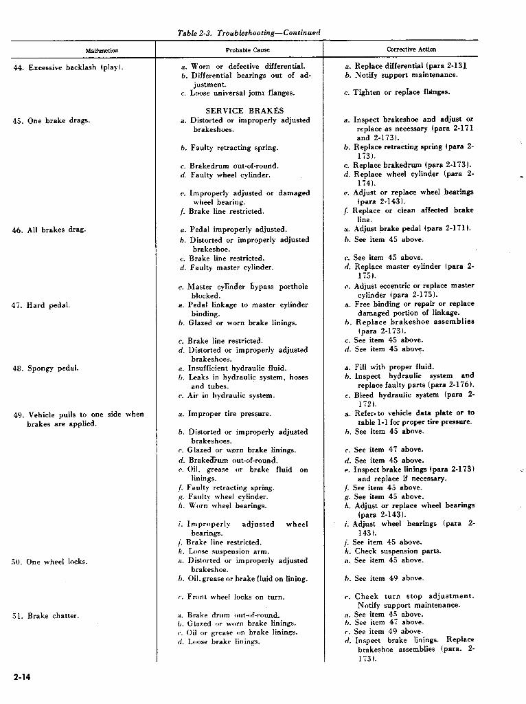
Malfunction
44. Excessive backlash (play I.
45. One brake drags.
46. All brakes drag.
47. Hard pedal.
48. Spongy pedal.
49. Vehicle pulls to one side when brakes are applied.
50. One wheel locks.
51. Brake chatter.
Table 2-3. Troubleshooting-Continued
Probable Cause
a. Worn or defective differential. b. Differential bearings out of ad-
justment. c. Loose universal jomr fianges.
SERVICE BRAKES a. Distorted or improperly adjusted
brakeshoes.
6. Faulty retracting spring.
:.
Brakedrum out-of-round. Faulty wheel cylinder.
Improperly adjusted or damaged wheel bearing.
Brake line restricted.
Pedal improperly adjusted.
Distorted or improperly adjusted
brakeshoe. Brake line restricted. Faulty master cylinder.
c. Master cylinder bypass porthole blocked.
a. Pedal linkage to master cylinder binding.
b. Glazed or worn brake linings.
c. Brake line restricted. d. Distorted or improperly adjusted
brakeshoes. a. Insufficient hydraulic fluid. h. Leaks in hydraulic system, hoses
and tubes. c. Air in hydraulic system.
a. Improper tire pressure.
b. Distorted or improperly adjusted brakeshoes.
c. Glazed or w.orn brake linings.
d. Brake&urn out-of-round. c. Oil. grease or brake fluid on
linings. /. Faulty retracting spring. p. Faulty wheel cylinder. II. Worn wheel bearings.
i. Improperly adjusted wheel bearings.
j. Brake line restricted. k. Loose suspension arm. il. Distorted or improperly adjusted
brakeshoe. l>. Oil. grease or brake fluid on lining.
(‘. Front wheel locks on turn.
X. Brake drum omit-~~f-rou& 6. Glazed or worn brake linings. c. Oil or grease on brake linings. cl. Loose brake linings.
Corrective Action
a. Replace differential (para Z-13) h. Notify support maintenance.
c. Tighten or replace flanges.
a. Inspect brakeshoe and adjust or replace as necessary (pars 2-171 and 2-173).
h. Replace retracting spring tpara 2- 1731.
c. Replace brakedrum (para 2-173). d. Replace wheel cylinder (para 2-
174). e. Adjust or replace wheel bearings
(para 2-143). 1. Replace or clean affected brake
line. a. Adjust brake pedal (para 2-171).
b. See item 45 above.
c. See item 45 above. d. Replace master cylinder (para 2-
1751.
c. Adjust eccentric or replace master cylinder (para 2-175).
a. Free binding or repair or replace damaged portion of linkage.
h. Reolace brakeshoe assemblies
c. d.
a.
h.
c.
a.
h.
(‘.
d. c.
(para 2-1731. See item 45 above. See item 45 above.
Fill with proper fluid. Inspect hydraulic system and replace faulty parts (para 2-176).
Bleed hydraulic system (para 2- 1721.
Refer. to vehicle data plate or to table l-1 for proper tire pressure.
See item 45 above.
See item 47 above.
See item 45 above. Inspect brake linings (para 2-173)
and replace if necessary. /. See item 45 above. g. See item 45 above. /I. Adjust or replace wheel bearings
(para 2-143). i. Adjust wheel bearings (pare 2-
143). j. See item 45 above. 12. Check suspension parts. a. See item 45 above.
b. See item 49 above.
c. Check turn stop adjustment. Notify support maintenance.
a. See item 45 above. 6. See item 47 above. c. See item 49 above. d. Inspect brake linings. Replace
brakeshoe assemblies (para. 2- 173).
i
2-14

Malfunction
32. Excessive pedal travel.
53. Pedal gradually goes to floor.
.j4. Brakes uneven.
55. Brakes grab.
56. Brakes fail completely.
37. Parking brake does not hold.
.38. Parking brake drags and over- heats.
59. Abnormal tire wear.
60. Wheel wobbles.
01. Backlash in steering.
Table 2-3. Troubledhooting-Continued
Probable Cause
a. Brakes out of adjustment. 6. Insufficient hydraulic fluid. V. Leaks in hydraulic system. n. Glazed or worn brake linings. a. Insufficient hydraulic fluid. h. Leaks in hydraulic system. c. Faulty master cylinder. a. Scored brakedrum. h. Incorrect adjustment. a. Distorted or improperly adjusted
brakeshoe.
h. Glazed or worn brake lining. c. Oil or grease on brake lining. d. Scored brakedrum. e. Dirt on drum or lining surface.
f. Faulty wheel cylinder. a. Insufficient hydraulic fluid. h. Leaks in hydraulic system. c. Air in hydraulic system. d. Faulty master cylinder. e. Linkage from pedal to master
cylinder disconnected or broken. J. Damage to hydraulic components.
PARKING BRAKE a. Brake band improperly adjusted. b. Brake lining worn or damaged.
c. Components coated with dirt or other contaminant.
d. Brake linkage damaged. a. Brake partially applied. b. Band improperly adjusted. c. Lining loose and damaged.
WHEELS AND TIRES a. Continual use of four-wheel drive
on hard surface roads and at speeds in excess of 35 mph.
h. Tire pressure low.
(1. Wheels. tires, or brakedrums out of balance.
a. Bent wheel. 0. Wheel bearings out of adjustment
or damaged.
STEERING 8. l’itman arm loose.
0. Worn or damaged parts in steering gear.
Corrective Action
a. Adjust brakes (para Z-1711. 11. See item 48 above. V. See item 48 above. rl. See item 47 above.
il. See item 48 above. h. See item 48 above. c. See item 46 above. a. Replace brakedrim (para Z-1 ‘73 1. 6. Adjust brakes (para Z-171 1. a. See item 4.5 above.
h. See item 47 above. c. See item 40 above.
(1. See item 54 above. c. Inspect and clean brakedrum and
shoe assemblies (para Z-173). 1. See item 45 above. a. See item 48 above. h. See item 48 above. c. See item 48 above. rl. See item 46 above. (‘. Free binding or repair or replace
damaged &ion of linkage. .1. Incorrect type of fluid. Drain,
flush and replace with non- petroleum base fluid IL0 933~?0- 218-l-“).
:J. Adjust lpara Z-167). h. Replace band and lining (para 2-
1681 also inspect drum. Replace drum if necessary (para Z-1691.
t’. Clean components if possible, replace parts as necessary.
(1. Replace damaged linkage. a. Release lever fully. h. Adjust lpara Z-167). c. Replace band and lining (para 2-
1081.
(1. Use four-wheel drive only when maximum traction is needed at speeds below 25 mph.
h. Correct tire pressure (refer to vehicle data plate or table l-1).
c. If wear is in front tires, adjust toe- in (para 2-150). If wear is in rear tires check rear suspension arms for damage or notify support maintenance.
(1. Replace as necessary.
a. Replace wheel. 6. Adjust bearings (para Z-1431 or
replace I para Z-141 and Z-1421. Notify support maintenance if wheel misalinement is suspected.
il. Tighten l’itman arm nut (para 2- 161 t.
6. Notify support maintenance.
2-15

62. Erratic steering. a. Incorrect front wheel alinement.
63. Hard steering.
64. Shimmy.
6.5. l’uli to one side.
06. Wander: body sway.
Table 2-3. Troubleshooting-Continued
Probable Cause
h. Incorrect steering gear ad- justment.
c. Loose steering linkage. d. Incorrect front wheel bearing
a.
h.
c.
d.
c. a.
h. c.
d.
e.
adjustment. Incorrect tire pressure.
Tires not of uniform size or wheels not matched (steel or magnesium 1.
Lack of lubrication.
Incorrect steering gear ad- justment.
Incorrect front wheel alinement. Incorrect tire pressure.
Incorrect front wheel alinement. Incorrect steering gear ad- justment.
Tires not of uniform size or wheels not matched (steel or magnesium ).
Loose steering linkage. /. Incorrect front wheel bearing
adjustment. R_ Weak front shock absorber.
/I. Loose or wnrn spindle support. i. Loose suspension. arm mounting
bolts. j. Loose crossmember mounting
bolts. k. Bent wheel. ii. Incorrect tire pressure.
0. Incorrect front wheel alinement. c. Tires not of uniform size or wheels
not of uniform weight (steel or magnesium t.
rf. Unequal brake adjustment.
I’. Incorrect front wheel bearing adjustment.
/. Bent spindle arm. g. Sagging or broken suspension
front spring. il. Incorrect tire pressure.
0. Tires not of uniform size or wheels not of uniform weight (steel or magnesium 1.
(‘. Loose steering linkage. tl. Incorrect steering gear ad-
justment. ,a. Loose steering gear mounting
bolts. ,1. Incorrect front wheel alinement. g. Bent spindle arm.
Corrective Action
a. Adjust toe-in (para 2-150). If
condition persists, notify support maintenance.
h. Notify support maintenance.
c. Tighten all loose connections. d. Adjust wheel bearings (para 2-
143). a. Inflate tires to proper pressure.
(Refer to vehicle data plate or table l-l 1.
c
h. Install tires of uniform size or match front wheels. +
c. Lubricate in accordance with LO
9-2320-218-12. d. Notify support maintenance.
c. Adjust toe-in (para 2-150). il. Inflate tires to proper pressure.
(Refer to vehicle data plate for table l-l ).
h. Notify support maintenance. C. Notify support maintenance.
d. See item 63. Ii condition persists, notify support maintenance.
P. Tighten steering linkage. J Adjust wheel bearings (para 2-
1431. A. Replace front shock absorber
lpara 2-144). It. Tighten. i. Tighten suspension arm mounting
loose bolts. j. Tighten crossmember mounting
loose bolts. k. Replace wheel. il. Inflate tires to proper pressure.
(Refer to vehicle data plate or table l-l ).
6. Adjust toe-in (para 2-150). c. See item 63: if condition persists.
notify support maintenance.
rl. Adjust service brakes lpara 2-
1711. Adjust wheel bearing (para 2-
1431. Replace spindle arm (para 2-164). Replace suspension front spring
(para 2-14.51. Inflate tires to proper pressure. Refer to vehicle data plate or table 1-I.
Refer to item 63.
Tighten steering linkage. Notify support maintenance.
Tighten steering gear mountmg Ioose bolts.
Adjust toe-in Ipara 2-1301. Replace spindle arm (para 2-164).
2-16

Table 2-3. Troubleshooting-Continued
Malfunction
66. Wander: body sway-Continued
Oi. Tires squeal on turns.
OH. Spring breakage.
00. Poor recovery or slow action of shock absorbers.
TO. Lack of spring control.
il. Oil leak at tappet cover. 72. Oil leak at rocker arm cover.
il. Erratic idling.
Probable Cause
II. Sagging or broken suspension arm.
i. Loose or worn spindle support.
j. Loose suspension arm mounting bolts.
k. Loose crossmember mounting bolts.
1. Defective shock absorbers.
a. Incorrect tire pressure.
h. Incorrect front wheel alinement. (‘.
a.
b.
a.
6.
(‘.
a .
b.
Bent spindle arm.
SPRING AND SHOCK ABSORBERS
Extremely rough handling of vehicle over rough terrain.
Lack of shock absorber resistance.
Shock absorber bushing binding or damaged.
No fluid in shock absorbers.
Loose mountings.
No fluid in shock absorbers.
Shock absorbers inoperative.
CRANKCASE VENTILATION
SYSTEM Restricted metering valve. a. Restricted metering valve.
I>. Loose cover hold-down nuts. a. Defective metering valve.
1). Leak or hole in line or fitting.
Corrective Action
k. Tighten crossmember mount loose - bolts. ’ Replace shock absorbers (nara 2. L.
il.
b. c.
a.
17.
a.
0.
144 and 2-1561. - Inflate tires to proper pressure.
(Refer to vehicle data plate or table I-11.
Adjust toe-in (para 2-1501. Replace spindle arm (yara 2-1641.
Reduce vehicle speed over rough terrain when possible.
Replace shock absorbers (pars 2- 144 and 2-1561.
Replace bushings (para 2-144 and 2-1561.
Replace shock absorbers (para 2- 144 and 2-156). -_
II. Replace suspension arm (para 2. 1461.
i. Tighten support; if condition is not corrected, notify support maintenance.
j. Tighten suspension arm mounting loose bolts.
c. Check bushings. If serviceable,- tighten shock absorber mounting nuts.
a. Replace shock absorber 144 and 2-156).
h. Replace shock absorber 144 and 2-156).
(para 2-
(para 2-
Clean metering valve (para -. 2-1221. a. Clean metering valve (para 2.
1221. I>. Tighten nuts to 18-24 in-lbs. a. Clean metering valve (para 2-
122t. 0. Replace defective line or fitting.
Section VI. TROUBLESHOOTING THE ELECTRICAL SYSTEM
2-19. General
a. This section contains detailed troubleshooting information for locating and correcting malfunc- tions in the electrical system. Each of the functional systems are treated separately, by means of-
(1) A physical and functional description. (2) A brief overall system check to determine
if the complete system is operating properly. (3) An illustration showing the location on the
vehicle of the major components of the system. (4) A simplified circuit diagram to clarify
circuits, circuit components and disconnect points.
(5) Step-by-step tests to diagnose trouble, using authorized test equipment.
b. This section also includes a list of electrical circuit numbers with a brief description of each, and a complete vehicle circuit diagram (fig. 2-43 and 2-44).
NOTE Electrical leads on the vehicle are marked with a circuit-numbered metal band at- tached to the junction or terminal end of each lead.
2-17

WARNING
Because of their higher power capabilities, 24-volt systems are more dangerous than 6- or 1 d-volt systems. Certain precautions must be observed before beginning any tests on the 24-volt system. Do not permit a “hot” wire to touch metal parts of the vehicle at any time. “Flash” testing by striking a hot wire against a vehicle ground will cause an arc that will completely destroy the connector on the lead. Ac- cidental contact of metal tools between battery or starter cables and the frame of the vehicle causes a direct short circuit resulting in arcing and instant heating of the tool to red heat. This can cause painful burns on the hands and serious damage to tools, vehicle components and batteries. Moreover, the overloaded battery may explode, spraying hot acid and sharp fragments over the surrounding area. The correct procedure when removing electrical equipment, harnesses, battery cables or starter cables, is to disconnect the battery ground cable first. Protect the ground cable from accidental contact with the battery terminal. When the work has been com- pleted, connect the battery ground cable last.
2-20. System Circuits
a. To successfully troubleshoot the electrical system, analyze the entire system as follows:
(1) Attempt to isolate the system (lighting, starting, etc.) in which the malfunction occurs.
(2) Isolate the circuit within the system that is not working.
(3) Isolate the individual component within the circuit that is causing the trouble.
b. Question the vehicle operator to obtain the maximum number of observed symptoms. The greater the number of symptoms of trouble that can be evaluated, the easier will be the isolation of the primary cause of defect. Since the operator of the vehicle, in most instances, can describe malfunc- tions only in terms of unsatisfactory vehicle per- formance, trained personnel should be capable of analyzing the operational symptoms to determine the primary cause of the malfunction.
c. The functional system circuits covered in this manual are in the following sequence:
1 Battery System Circuit 2 Starting System Circuit 3 Generating System Circuit 4 Ignition System Circuit 5 Lighting System Circuits 6 Directional Signal
System Circuit 7 Instruments. Gages and
Horn Systems Circuits 8 Fuel Supply System
Circuit
‘qirre 2.1;” 2-18 and 2-10 2-20 through 2-26 2-2i through 2-20 2-30 through 2-3i 2-34 through 2-3i
2-38 through Z-40
2-41
2-21. Test Equipment
a. Description. (1) Low voltage circuit tester. Figures 2-3
through 2-6 illustrate some of the types of Low Voltage Circuit Testers (LVCT) in general use. The LVCT consists of a voltmeter, an ammeter, a fixed resistance, load bank, and field rheostat unit. They are mounted in a metal case, which also provides stowage space! for the meter leads and accessories (fig. 2-7) used for making ‘all the necessary tests. Other test sets are similar, and all test described in this section can be performed equally well with these testers. Figure 2-9 shows a schematic diagram of two typical testers, to better understand how the tester components function with the circuit being tested.
2-18

6
AT 9539
1 External shunt binding posts
A-Negative B-Positive
:! Ammeter binding posts _ _ A-Positive
B-100 amp negative C-50 amp negative D-10 amp negative Ammeter
Load bank control Load bank switch Lcpad bank binding posts A-Commcm
7
8 0
10 II
12
B-O volts, S-100 ‘A
C-l:! volts, SO-100 _. ._I.
A 11-11’ volts. S-.50 A-24 volts. 80-100 A
E;-24 volts. 10-80A F-2 4 volts. 3-10 A 1 / 4-ohm resistor binding posts Field rheostat control
Field rheostat binding posts Voltmeter range selector switch Voltmeter binding posts A-Positive B-Negative Voltmeter
/:iprrrc* ,‘-.‘I. I,OIC zwltage circuit tester TV-l 00-FSN 491 O-992-91 36.
2-19

3 ?
e + AMMETER
i
VOLTMETER
FIELD RHEOSTAT
I I I
13 12
AT 9540
1 Esternal shunt binding posts A-Negative B-Positive
2 Ammeter binding posts A-Positive
B-l 00 amp negative C-30 amp negative I)- 10 amp negative
3 Ammeter
4 Load bank control. coarse .i Load bank switch 0 Load bank control. fine
7 Vohmeter~ range selector switch
8 Voltmeter 0 Voltmeter bind posts
A-Positive
B-Negative 10 1 / 4-ohm resistor binding posts
11 Field rheostat control 12 Field rheostat binding posts 13 Load bank binding posts
A-Common
B--h volts c-12 volts D-24 volts
I*‘igtrrc~ 2-L IANC whge circuit tester EMC 1060-FSN 491 O-092-9136.
2-20

\ ,. -z- Ammeter binding posts A-10 amp negative B-.50 amp negative C-100 amp negative
I)--Positive Load bank link. 12 volt
bzsternal shunt binding posts A-l’ositive
B-Negative C--Disconnect link Ammeter
Load bank control. coarse Load bank control. fine
AT 9.541
i Load ban1 switch 8 Voltmeter range selector switch 0 Voltmeter
10 Voltmeter binding posts
A-Positive B-Negative
11 Field rheostat control I:! Field rheostat binding posts 13 I / 4-ohm resistor binding posts
14 Load bank binding posts A-Common
B-24 volts
C-l :! volts
b‘igrr rv P-5. I,OIC rwhge circuit’ tester al/en JO-92-FSN 4910-092-9136.
2-21

AT 9542
1 2
3
4
3 6 7 8 0
10
11
I:!
1s
Field rheostat control 1 / 4-ohm resistor binding posts
Voltmeter binding posts A-Positive B-Negative
Voltmeter Vc$tmeter range selector switch L&d bank switch Load bank control. coarse ._ Load bank control. fine
Ammeter Ammeter binding posts
A-Positive
B- 100 amp negative
C --5O amp nkgative
D-10 amp negative External shunt binding posts
A-Negative B-Positive Load bank binding posts
A-24 volts B-12 volt link
c-12 volts D-6 volt link
E-6 volts F-Common
Field rheostat binding posts
(2) Adapter set& At present, there are several adapter sets in use. They are interchangeable, differing only in design. Adapter sets are used for making external connections to the waterproof electrical system on military vehicles. Figure 2-8 illustrates a typical adapter set.
(3) Multimeter. The multimeter (fig. 2-10) is a lightweight portable instrument for use in making voltage tests where load banks or ammeter ranges are not required. The multimeter is also useful in making resistance or continuity tests of components suspected of being open, intermittent, or short- circuited.
b. Low Voltage Circuit Tester Functions and Use.
NOTE
_,
The key numbers noted in parentheses are in figure 2-3, except where otherwise noted.
(1) Voltmeter. The two voltmeter binding posts ( 1 l), marked positive (-I- ) and negative (-) are used for making voltage tests of batteries, generators or wiring circuits. Four meter ranges ( 1, 10, 20 and 50 volts) are available, selected by the voltmeter range selector switch (10).
(2) Ammeter. Four ammeter binding posts (2) are provided for making current readings up to 100 amperes. One terminal (A) is a common positive (+ ) terminal ; the others (B,C, D ) provide a selection of three negative ranges of lo1 50, or 100 amperes. Two binding posts (1) are provided for the connection of an external shunt assembly to extend the ammeter range to 500 amperes for the measurement of heavy currents.
(3 1 Fixed l/4-Ohm Resistance Unit. Two binding posts (‘7) provide a fixed 1 / 4-ohm resistance for use in charging circuit tests. Although the ammeter is used for these tests, the 1 / 4-ohm resistor has not internal con’nection to the ammeter.
Figure 2-6. I,ou: dtage circuit tester RAM
62F151-FSN 4910-092-91.36.
2-22

EXIESNAL SHUNT AMMETER LEADS
POSlTIVE !RED) NEGA:‘%M ;GCACK I POSITWE (RED i
Test leads for use &th low uoltage circuit testers.
j’ipclrp P-8. Engine electrical test adapter set No. 17-A-3150-FSV 491 O-348-7600.
2-23

Al Y34.l
I-‘iguw Y-9. Srhcmatic layout of LA Coltage circuit testers (typical).
2-24

DC SCALE
SCALE SELECTOR
OHMS SCALE
DC SCALES
RANGE SELECTOR
MULTIMETER 6625X3-1438 IS A COMPONENT OF TOOL KITS, AUTOMOTIVE MAINTENANCE, ORGANIZATIONAL, SET NO. 1, SUPPLEMENTAL (SM9-4-5180-A17), AND SET NO. 2, SUPPLEMENTAL (SM9-4-494O-A08).
OHMS ADJ.
AT 9544
Figurr Z-10. Multimeter-FSN 6625-543-1438.
(4) Field rheostat unit. Two binding posts (91 provide a changeable resistance for use in generator and charging circuit tests. There is no internal connection between the field rheostat unit and any other component of the tester.
(5) Load bank. Six binding posts (61 provide the proper load resistances to set up generator charging rate tests for various battery and generator voltages. The common binding post (6Al is connected internally to the ammeter positive (+ 1 binding post (2Al eliminating the need for a jumper lead when making load tests. The load resistance may be changed by the load bank control knob (41 or removed from the circuit by the load bank switch (51.
c. Multimeter Functions and Use. (1) VoItmeter. The voltmeter (fig. 2-11) is
similar to the ‘voltmeter portion of the LVCT. Three meter ranges (2.5, 10 and 50 volts) are available for use in automotive testing. Two ad- ditional ranges (250 and 1000 volts) are useful in
testing electronic equipment. Ranges are selected by the range selector switch.
(21 Ohmmeter. The ohmmeter (figs. 2-12 and 2-l 3 1 is used for making resistance and continuity tests. The ohmmeter is basically a voltmeter and internal battery connected in series, so that when the two test leads are connected together, the voltmeter reads the battery voltage. When a conductive circuit is connected between the test leads, the voltmeter will indicate how much voltage is being lost (voltage drop) in the circuit. In the case of a length of wire, there will be little or no voltage drop; for a small coil or a resistor, there may be considerable voltage drop. The amount of voltage drop is directly related to the resistance (in ohms) of the component being tested.
(31 Other scales. Since the multimeter is a general purpose instrument intended primarily for electronic testing, other scales and ranges are provided. These ranges are not normally used for automotive vehicle electrical troubleshooting, and are beyond the scope of this manual.
2-25

DC VOLTAGE TEST
Fi,tiurc 2-l I. DC voltage test with multimeter.
(USED TO MEASURE BATTERY OR GENERATOR VOLTAGE)
1. SET SCALE SELECTOR ON +DC.
2. SET RANGE SELECTOR SWITCH ON 5OV.
3. CONNECT NEGATIVE LEAD (BLACK) TO VEHICLE FRAME.
4. TOUCH POSITIVE LEAD (RED) TO TERMINAL POST OF BATTERY. NEEDLE SHOULD MOVE TOWARD CENTER OF SCALE TO INDICATE VOLTAGE.
AT 9545
RELAY 6.
RESISTANCE TEST
(USED TO MEASURE RESISTANCE OF COILS OR RESISTORS, AND TO LOCATE SHORT CIRCUITS)
1.
2.
3.
4.
5.
7.
8.
9.
SET SCALE SELECTOR SWITCH ON +DC.
SET RANGE SELECTOR SWITCH ON Rxl.
TOUCH METER LEADS TOGETHER AND TURN ZERO OHMS ADJUST UNTIL NEEDLE IS ON “0” OHMS.
MAKE SURE THERE IS NO BATTERY VOLTAGE CONNECTED TO CIRCUIT TO BE TESTED.
ATTACH NEGATIVE LEAD (BUCK) TO VEHICLE FRAME.
TOUCH POSITIVE LEAD (RED) ~0 TERMINAL OF COMPONENT BEING TESTED.
READ RESISTANCE ON METER SCALE.
IF METER NEEDLE DOES NOT MOVE, CIRCUIT IS OPEN.
IF METER NEEDLE MOVES COMPLETELY ACROSS SCALE TO “0” A SHORT CIRCUIT EXISTS, OR A HEAVY-DUTY COMPONENT WITH VERY LOW RESISTANCE.
AT 9546
I,‘iprrrra J-12. Kcsbtance test with multimeter.
2-26

Z-22. General Instructions for Use of Test Sets and Multimeter
CAUTION Before proceeding with vehicle troubleshooting procedures, paragraphs 2- 23 and 2-24 must be read and understood by all personnel using the test set. Incorrect connections to the test set could result in costly damage to test equipment or vehicle componets.
a. Be sure of the test .to he made and the procedure to be used. Follow the step-by-step procedure given for each individual test.
b. Always select a meter range higher than the expected reading. Set the tester for this range before connecting it into the circuit.
c. Be sure to read the correct row of meter scale figures which correspond to the selected range. The range selector switch or the binding post marking always shows the right-hand figure of the row to be used. For example, if the range selector is set for 50 volts, read the row of meter scale figures that ends with 50 on the right-hand end.
d. When testing with an ammeter or ammeter shunt, always connect it in series with circuit to be tested. For maximum safety, the power should be turned off when connecting or disconnecting the ammeter or ammeter shunt.
e. When testing with a voltmeter, always connect it in parallel with (across) the terminals of the component to be tested. Where the terminals are easily accessible, the power need not be turned off to make voltage tests. Where there is a possibility of touching an adjacent terminal or the vehicle frame when attaching the positive test lead clip, the power should be off and the test lead clipped securely to the terminal to be tested before restoring power.
CAUTION Never attempt to make resistance tests until all sources of power connected to the circuit or device to be tested are discon- nected. The multimeter will be damaged if this procedure is not followed.
f. When testing with an ohmmeter, always connect it in parallel with (across) the terminals of the component to be tested. (If the component has only a single terminal, connect between the ter- minal and the frame of the component or vehicle). In addition, the component being tested must be electrically free from the circuit. Remove all connections to the component before making any resistance or continuity tests. (One terminal of most automotive electrical components is connected to ’ the vehicle frame. However, the component may remain mounted in the vehicle provided all other circuit connections have been removed. 1
g. Always handle the test sets carefully Although the test set is ruggedly built, the meter movements are delicate mechanisms and can be damaged easily by rough handling. Be sure to stow all test leads and adapters in their proper com- partments after the tests have been completed.
CAUTION In choosing a location for the low voltage circuit tester, at the vehicle or on the bench, be sure to place the tester in a position that will not restrict the air flow through the bottom and top openings. Do not exceed the duty cycle of 3 minutes “on” and 27 minutes “off”.
2-23. Specific Instructions for Use of the LOW Voltage Circuit Testers
NOTE Complete detailed information on 10~ voltage circuit testers is contained in TM 9- 4910-402-12.
NOTE The key numbers noted in parentheses are in figure 2-3, except where otherwise noted.
a. D. C. Voltage Tests. (1) Determine exactly what is to be tested,
where the test leads will be connected, and what voltage to expect.
(21 Voltage must be measured at the exact circuit point specified in Electrical Troubleshooting tests. Resistance of poor wiring, connections, and switch contacts can cause errors if voltages are measured at points elsewhere in the circuit or on other parts of the component.
(31 Connect the voltmeter test leads (fig. 2-71 to the voltmeter binding posts (11, fig. 2-3). Connect the black lead to the negative t-1 post (Bl, and the red lead to the positive (+ 1 post (Al.
(41 Set the voltage range selector switch to a range higher than the expected voltage. Determine exactly which row of figures you will read.
CAUTION (4 1 must be done before (5 1. A voltage range setting lower than the circuit voltage will damage the meter when (6) is per- formed.
(5) Connect the negative (black) lead first to the circuit to be tested. This will usually be the vehicle frame, or a similar ground point (fig. 2-141.
(6) Touch the positive (red) lead to the other circuit connection. If the meter needle moves to the left, reverse the test leads at the circuit-not at the tester binding posts.
(‘71 Read the voltage carefully, facing the meter squarely. Viewing the meter from an angle will result in inaccurate readings.
b. D. C. Current Tests. .
2-27
(I) Determine exactly what is to be tested. Where the test leads will be connected, and what amperage to expect.
(2) Amperage may be measured at any convenient point in a single circuit, since the current is always the same throughout the circuit.
(3) Connect the ammeter red test lead (fig. 2- 7 1 to the positive (+ 1 binding post (2A, fig. 2-3). Tighten the binding post securely.
(4) Select a negative binding post (2B, C or D, fig. 2-3 1 marked with an amperage range higher than the expected amperage. Connect the ammeter black test lead (fig. 2-7) to this selected binding post and tighten the binding post securely. Determine exactly which row of figures on the ammeter you will read.
the
CAUTION (4) must be done before (5). An amperage range lower than the circuit current will damage the meter when (6) is performed. (5 1 Be sure that no power is being applied to
circuit to he tested. Separate the circuit at a convenient junction point to form two connection points. Connect the red wire to the connection point which is electrically closer to the battery positive (+ ) terminal. Connect the black wire to the other connection point (fig. 2-14).
(6) Apply power to the circuit momentarily, observing the ammeter. The needle should move to the right. If the needle moves to the left, in- terchange the red and black wires at the circuit test points-not at the tester binding posts.
(7) Read the ammeter carefully, facing the meter squarely. Viewing the meter from an angle will result in inaccurate readings.
(8) Remove the power from the circuit before disconnecting the test leads.
c. D. C. Current Tests with Ammeter Shunt. (1) When amperage exceeding 100 amperes is
expected, the external shunt assembly (fig. 2-7) should be used. The shunt assembly consists essentially of a power resistor which absorbs 98 percent of the circuit amperes and allows only 2 percent to be sent to the meter. Thus, if the circuit current was 200 amperes, 196 amperes would be absorbed by the shunt and 4 amperes would be indicated on the meter. The SOO-ampere figures on the meter scale are used for this shunt. A 200- ampere current through the shunt will indicate a reading of 200 on the meter scale, although a current of only 4 amperes is actually flowing through the meter.
(2) Disconnect the power to the circuit to be tested. Connect the small diameter shunt leads to the shunt binding posts of the tester (I, fig. 2-3) ; the red lead to the positive (+ ) binding post (B) and the black lead to the negative (-) binding post (A).
2-28
(3) Connect the heavy shunt leads to the circuit to be tested (fig. 2-14). Make sure all connections are tight.
(4) Follow all instructions given in b (5), (6), (7) and (8) above.
d. Load Bank and Field Resistance Tests (1) Three or more sections of the tester are
used for these tests; the voltmeter, ammeter, and one or more of the resistances. Use extreme caution when connecting the test leads; severe damage can be caused to the tester and the components being tested if the test setup is incorrect. Follow the in- dividual test setup illustration for the specific test being made. Figure 2-14 shows an example of a test of this type.
(2 ) Observe precautions in a and b above, for use of the voltmeter and ammeter.
(3) Both the LOAD BANK (4, fig. 2-3) and FIELD RHEOSTAT (8, fig. 2-3) knobs should bt in the extreme counterclockwise position before connecting the load bank or field rheostat to the circuit being tested.
NOTE The nameplates on the LOAD BANK and FIELD RHEOSTAT controls indicate clockwise rotation is required for an in- crease in current. However, to accomplish this effect, the actual resistance presented to the circuit is decreased with clockwise rotation of these controls. Refer to figure 2- 9. (4 1 Whenever resistances carry heavy
currents, considerable heat is developed. To prevent heat damage to the resistors and other tester components, power should be applied to the resistors for not more than three minutes con- tinuously. At least 27 minutes off time is required to allow the resistors to cool down sufficiently for another three-minute period of operation. Be sure there is sufficient ventilation provided for the tester. Before applying power to the circuit, have all connections in place and be ready to make the necessary adjustments and meter readings as rapidly as possible, consistent with accuracy and safety.
(5) Do not turn the LOAD BANK SWITCH (5, fig. 2-3 1 to OFF position while power is applied to the circuits. The switch contacts will arc and burn when subjected to heavy battery current.
Z-24. Specific Instructions for Use of the Multimeter
a. D. C. Voltage Tests. (1 j Determine exactly what is to be tested,
where the test leads will he connected, and what voltage to expect.
(2) Voltage must be measured at the exact circuit point specified in the Electrical

Troubleshooting tests. Resistance of ‘po’dr wiring, connections, and switch contacts can cause errors if voltages are measured at points elsewhere in the circuit.
(3) Plug the voltmeter test leads (fig. 2-10) /into the multimeter jacks. Plug the black lead into (the jack marked “COMMON” and the red lead into the jack marked “+ “.
(4) Set the voltage range selector switch to a range higher than the expected voltage. Determine exactly which row of figures you will read.
CAUTION .(4) must be done before (5). A voltage range setting lower than the circuit voltage will damage the meter when (6) is per- formed. (5) Connect the negative (black) lead first to
the circuit to be tested. This will usually be the chassis frame, or a similar ground point (fig. 2-11).
(6) Touch the positive (red) lead to the other circuit connection. If the meter needle moves to the
left, reverse the test leads at the circuit-not at the tester binding posts.
(7 1 Read the voltage carefully, facing the meter squarely. Viewing the meter from an angle will result in inaccurate readings.
b. Resistance Tests. CAUTION
Never attempt to make resistance tests until all sources of power connected to the circuit or device to be tested are discon- nected. The multimeter will be damaged if this procedure is not followed.
All electrical circuits possess some resistance. Some resistances, however, are so small and others so large that they cannot be read on the same scale. When a reading is obtained, it indicates the circuit had continuity (no break or openings). The following procedure must be followed to perform resistance or continuity tests :
-
CONTINUITY TEST
(USED TO TEST FOR CABLE BREAKS, LOOSE WIRES, BURNT OUT LAMPS OR OTHER ITEMS)
1.
2.
3.
4.
5.
6.
7.
SET SCALE SELECTOR ON +DC.
SET RANGE SELECTOR SWITCH ON Rxl.
BE SURE THERE IS NO BATTERY VOLTAGE CONNECTED TO CIRCUIT TO BE TESTED.
ATTACH NEGATIVE LEAD (BLACK) TO ONE END OF CIRCUIT.
TOUCH POSITIVE LEAD (RED) TO OTHER END OF CIRCUIT. NEEDLE SHOULD MOVE TO RIGHT HAND END OF SCALE.
IF NEEDLE DOESN’T MOVE, CIRCUIT IS OPEN, OR LAMP IS BURNT OUT, OR COMPONENT OPEN.
IF NEEDLE FLICKERS, OR JUMPS BACK AND FORTH, LOOSE CONNECTIONS ARE INDICATED.
AT 9547
I*‘igrrw Z-13. Continuit>’ test with multimeter.
2-29

(I) Place the SCALE SELECTOR switch (fig. 2-10) in the + D. C. position.
(2) Rotate the range selector switch to the required range to t I ) R X 1 to measure resistance between 0 and 2,000 ohms and to test for con- tinuity, (2 1 R X 100 to measure resistance between 0 and 200,000 ohms. and (3) R X 10,000 to measure resistance between 0 and 20 megohms (megohms = million ohms I.
(3 1 Plug the black lead into the jack marked COMMON and the red lead into the jack marked “+“. Touch the ends of the leads together and turn the ZERO OHMS knob until the pointer is at zero.
(4) Separate the ends of the test leads, and clip the leads across the portion of the circuit or component being tested (figs. 2-12 and 2-13). (Either of the leads may be clipped to the test points.)
(5) Read the ohms on the black area at the top of the scale.
NOTE For range R X 1, read the figures directly, for range R X 100 multiply the reading indicated .by 100 or add two zeros to the reading; for range R X 10,000 multiply the reading indicated by 10,OOq or add four zeros to the reading.
Example: A 20.000-ohm resistance should be checked on the R X 100 range scale. The reading on the scale will be 200. Adding two zeros will give
20,000 ohms. (A) An infinite reading is an open circuit
reading. There will be no movement of the multimeter pointer on the R X 1 when an open circuit exists. This usually indicates a broken con- nection somehere. Infinite position on the ohm- meter range scale is marked with the symbol.
2-30

DISCONNECT POSITIVE BATTERY CABLE, ATTACH + AMP
LEAD TO BATTERY POST \
SET TO 50-VOLT RANGE BEFORE CONNECTING CLIPS
+ I- I BLACK I
RED / I
STARTER OR OTHER COMPONENT WITH LESS THAN lOO- AMPERE DRAW
I I
B. AMMETER TEST
CLIP THIS LEAD FIRST LINKS OPEN
A. VOLTMETER TEST ADJUST
FIELD RHEOSTAT TO MINIMUM
OF 30 AMPS AT 30 VOLTS
DISCONNECT BATTERY GROUND CABLE AND CONNECT SHUNT TO BATTERY POST AND CABLE AS SHOWN.
I \ \ CONNECT TO
GENERATOR FRAME
EXTERNAL SHUNT RE’
LINK CLOSED
/ GULATOR
REMOVE BATTERY CABLE WHILE
MAKING HOOKUP
C. AMMETER TEST WITH EXTERNAL SHUNT ._ D. LOAD BANK AND FIELD RESISTANCE TEST AT 9548
/.‘;,q,,~,, 2.1 /. 7’ . . . 1. !/>I’ 4 .r~r;rn#c~ftic~rils II/ losfs tciih 101~~ ~wll;~p c.irrrcil lcslvr TV-1 00.

.(‘7) A zero reading indicates a continuous circuit with resistance too low to be measured with the multimeter. Where two cable wires, or a circuit wire and a ground connection are being checked, this usually indicates a short circuit somewhere.
Z-25. Troubleshooting Electrical System
a. Preliminary Battery Check. The vehicle battery condition should be checked prior to performing any electrical checks in the vehicle. The vehicle has two 12-volt batteries connected in series, furnishing 24 volts to the electrical system (fig. 2-15) which uses a negative (-) ground and a positive (+ 1 power feed to the electrical com- ponents. To test the battery condition, turn the ignition switch to ON (without starting the engine). Observe the battery indicator (fig. 2-15). Start the engine, accelerate to about 1200 rpm, and again observe the battery indicator. If the indicator observations show that further tests are required, refer to the Electrical Troubleshooting tests, Battery System (fig. 2-17).
b. Specific Gravity Check. A specific gravity check should be made with a hydrometer as a routine check before making further tests. Observe the following precautions when making this check:
(1) Hold the hydrometer vertically, so the float does not touch the sides of the glass barrel. Be certain that the barrel is not so full of electrolyte that the float is stopped at the top. Read straight
across the top of the liquid ; disregard the curvature of the liquid at the edge of the glass and float.
(2) The electrolyte in a cell should be at the normal level when the reading is taken. If the level is below normal, the reading will be high. On the other hand, if the battery has been overfilled, the electrolyte will be weakened and the reading will be low.
(3) When water is added, it will tend to remain at the top of the cell and a hydrometer reading will be inaccurate. If it is necessary to add water to the battery before taking a reading, the battery should be charged for 1 or 2 hours to mix the electrolyte before the hydrometer is used. This may be done by connecting the battery to a charger or by operating the vehicle.
(4) Gravity readings may also be misleading if taken immediately after a battery has been discharged at a high rate, such as in prolonged cranking. Wait several hours before taking a specific gravity reading.
(5 I When the temperature of the electrolyte is much greater or much less than 80°F., the specific gravity indication on the hydrometer will not be accurate. A temperature correction must be applied to the reading to obtain the correct specific gravity. Figure 2-16 shows the amount of temperature correction to be applied. and how to estimate the condition of the battery from the temperature- corrected specific gravity.
/ 2-32

BATTERY- TO-BATTERY
CABLE
VEHICLE POWER CABLE
I VEHICLE BATTERY GROUND
READING
, ENGINE RUNNING AT MAXIMUM CHARGING
ELECTRICAL UNITS SPEED LONG ENOUGH ~\
OFF; RUN ENGINE TO CHARGE BATTERY, WITH ALL ELECTRICAL UNITS
CHARGING RATE. TURNED ON, POINTER
IF VOLTAGE
li J.
SHOULD STAY IN GREEN
REGULATOR IS SECTION. IF NOT,
PROPERLY SET, VOLTAGE REGULATOR IS
POINTER WILL FALL SET TOO LOW, OR BATTERY
IN TOP HALF OF =- IS WORN OUT.
. _. ~. -. \
--- OVERCHARGE SECTION. CHECK FOR MALADJUSTED OR DEFECTIVE VOLTAGE RE-
\ GULATOR.
B. BATTERY AT REST - IGNITION SWITCH “ON”. C. BATTERY IN USE - ENGINE RUNNING
AT 9549

CORRECTED SPECIFIC GRAVITY
1.280 1.250 1.220 1.190 1.160 1.130
Malfunction Circuit TM
1. Vehicle will not crank- All elec- trical systems inoperative or weak.
120°F
1 lOoF
lOOoF
90°F
- +0.016
- +0.012
- +o.OOa
- +0.004
NORMAL - 8O0F
BATTERY COkDlTlON
FULLY CHARGED THREE-FOURTH CHARGED 200F ONE-HALF CHARGED ONE-FOURTH CHARGED LITTLE USEFUL CHARGE O°F DISCHARGED
t
;
._o_ :
70°F
60°F
50°F
40°F
30°F
-10 F
-2O’F
- - -0.004
- - -0.008
* - -0.012
- - 0.016
* - -0.020
- - -0.024
- - - 0.020
- - - 0.032
- - - 0.036
I*‘iArurc 2-I 6. IIydromcter temperature correction chart.
Table 2-4. Electrical Troubleshooting
BATTERY SYSTEM CIKCUIT (fig. 2-171
DESCRIPTION : TWO 12-volt batteries are connected in series to provide 24 volts for the operation of all electrical
equipment on the vehicle. The negative terminal of one battery is connected to the vehicle frame, and the positive terminal of the other battery is connected directly to the starter switch, for distribution to other electrical systems on the vehicle. The batteries and cables are waterproofed.
Test 1. Make a visual inspection. Look for broken. cracked, or distorted battery cases. Check for loose terminals. Check for corrosion on the battery terminals. cables, battery hold-down and around battery posts. Check the cables for frayed or worn insulation. Check the electrolyte level in each cell. If the level is below the plates, the battery may be permanently damaged. Also look for dirt. oil or other contaminants floating in the electrolyte. Perform all required cleanup and make necessary repairs before proceeding with further tests.
Test 2. Check each cell for specific gravity of battery electrolyte with bydrometer. (refer to para 2-25.1 Batteries must test 1.225, or greater,
temperature corrected. and each cell must test within 25 gravity points of the others. If variation is more than 23 points. charge batteries fully, and recheck specific gravity on all cells. If 25-point variation still exists, one or both batteries are defective.
2-34

ADJUST TO 100 AMPERE CURRENT DRAW I - +
V 12v 12v a -I’,’ +
c A + -
= -- 50-VOLT RANGE
TEST 3. BATTERY LOAD TEST
ADJUST TO 100 AMPERE CURRENT DRAW
20 VOLT RANGE /+
TEST 4. INDIVIDUAL BATTERY TEST SHIFT VOLTMETER
c RL” ,
TEST 5. INDIVIDUAL BATTERY TEST (COMPANION) AT 955’
ADJUST TO 100 AMPERE CURRENT
DRAW

Table 2-4. Electrical Troubleshooting-Continued
Circuit Test
;.OH Test 3. Test batteries under load to determine their ability to crank engine under starting conditions, and to determine maximum voltage drop with a 1 OO-ampere load for 13 seconds. Turn load bank switch “OFF” with load bank control completely counterclockwise. Set voltmeter range selector switch to 30 volts. Connect circuit tester to batteries as shown in figure 2- 17. test 3. Turn load bank switch “ON” and rotate load bank knob clock- wise. watching ammeter scale until 100 amperes is indicated. Voltmeter shc1uld read not less than 18 volts during test, and 24 to 26 volts before and after test. If less. perform tests 4 and 5 to test individual batteries.
NOTE Tests 4 and .i use the same circuit tester setup as test 3, except that the voltmeter leads are moved to test the voltage of each individual battery.
Test 4. ‘l’est individual batteries to determine maximum voltage drop with a ItlO-ampere load for 1 .i seconds, or if each has a maximum variation of 22 volts c1f the other. Turn load bank switch “OFF” with load bank control onnpletely counterclockwise. Set voltmeter range selector switch to 20 volts. Connect circuit tester to batteries as shown in figure 2-17, test 4. Turn h1ad bank switch “ON” and rotate load bank knob clockwise, watching ammeter scale until 100 amperes is indicated. Voltmeter should indicate 9 v(1lts or more. If less than 0 volts. battery is discharged or defective. Charge battery and retest.
Test .i. Same as test 4. on the other battery. Voltage should not fall below 9 volts or be more than 0.2 volts higher or lower than the other battery.
STARTING SYSTEM CIRCUIT (fig. 2-181
The starting system consists of the battery. starting motor assembly. starter switch and connecting cables. The starting motor is energized by depressing the starter switch. Current flows from the positive tcwninal c1f the battery. through the battery-to-switch cable, through the switch through the switch-to- starter cable. through the starter, to the vehicle frame. and through the frame to the negative terminal of the battery. Faulty connections contribute largely to starter system failures.
I
Malfunction
3. Starter fails tt1 crank or crank: slowly.
Circuit
o.;.oti
Test
NOTE Check condition of battery as shown by battery-generator indicator. Hattrry must be in good condition before making these tests. (See para ‘-2.5. I
Test I. Make a visual inspection. Examine the starter terminal studs, battery trrminals. and the engine ground strap to be certain that no loose or dirty electrical connections exist. While cranking with the starter. grasp all of the batters clamps and the battery-to-frame connection. A sensation of heat at any of these points indicates a poor connection. If the starter runs at a high rate of speed. but will not turn the engine. the overrun clutch is usually faulty. If this condition esists remove the starter and replace the clutch. If the starter does not crank at all or cranks slowly. perform the fc1llowing tests:
2-36

i
I I. TEST 2. STARTER VOLTAGE TEST
- 5z TEST 3. BATTERY GROUND CABLE TEST
2v 12v +- + n
I IP
I
+v-
ta a
S
F
TEST 4. BATTERY-TO-BATTERY CABLE TEST
SCRAPE 1
7 POST CLAMP BATTERY TERMINAL
NOTE: WHEN MAKING THESE TESTS, HOLD METER PROBE FIRMLY ON BATTERY POST - NOT ON CLAMP.
AT 9552

Table 2-4. Electrical Troubleshooting-Continued
Malfunction
13. Starter fails to crank or cranks slowly-Continued
NOTE Coat all battery terminal post clamps with light grease after tests have been cornpIe@.
STARTING SYSTEM CIRCUIT (fig. 2-18)
Circuit
6.i.68
68
0,;.08
Teat
NOTE All reference to ground for following tests pertains to vehicle frame.
Test 2. Perform the starter voltage test. Connect low voltage circuit tester (SO-volt range1 between starter terminal and starter frame as shown in fig- ure 2-J8, test 2. With the ignition switch off, depress starter switch. If reading is 18.5 volts or more, starting switch. cables and batteries,are not the cause of slow cranking. Check for tight engine or defective starter. If reading is less than 18.5 volts. perform test 3.
Test 3. Perform the battery ground cable test. Connect low voltage circuit tester (50~volt rangel between battery ground terminal and starter frame as shown in figure 2-18. test 3. With the ignition switch off, depress starter switch. If voltmeter shows no or low reading, switch the voltmeter range selector to a lower range until a reading is obtained or the l-volt range is reached. If reading is more than 0.1 volt, remoye battery ground cable and battery terminal post clamp. Clean battery terminal post and battery terminal post clamp with wire brush. Re-install battery cable and terminal
,post clamp and tighten all bolts securely to assure a good electrical con- nection. Perform test again. If the voltage reading is still more than 0.1 volt. install a new cable, and retest. If starter still cranks slowly. perform test 4.
Test 4. Perform battery-to-battery cable test. Connect low voltage circuit tester IX-volt rangel acorss battery-to-battery cable. Contact the actual battery posts. and not the terminal post clamp. with positive and negative test leads as shown in fiie 2-18. test 4. With the ignition switch off, depress starter switch. If voltmeter shows no or low reading, switch the voltmeter range selector to a lower range until a reading is obtained or the l- volt range is reached. If reading is 0.1 volts or less. cable is serviceable. If reading is 0.1 or more, remove the battery-to-battery cable. Clean the battery terminal posts and the terminal post clamps on the cable with a wire brush. Re-install the cable and tighten all bolts securely to assure a good electrical connection. Perform test again. If the voltage is still more than 0. I volt. install a new cable. and retest. If the starter still cranks slowly. perform test 3.
Test .5. Perform battery positive terminal test. Connect the low voltage &cuit tester 150~volt range) between the battery positive post and its terminal post clamp as shown in figure 2-19. test 5. With the ignition switch off. depress the starter switch. If the voltmeter shows no or low reading. svitch the voltmeter range selector to a lower range until a reading is ob- tained or the l-volt range is reached. If the reading is more than 0.1 volt, timwe the battery-to-starter switch terminal post clamp and ckan the battery terminal post and the terminal post clamp with a wire brush. Rt- install the cable and tighten all bolts securely to assure a good electrical c-mm&on. Perform test again. If the voltage is still more than 0.1. volt. install a new cable and retest. If the starter still cranks slowly. perform test (I.
Teat O. Perform engine-to-frame ground strap test. Connect low voltage circuit tester 1.50~volt range) negative lead (black wire) to terminal post clamp of the negative (grounded) battery terminal. Connect the positive meter lead (red wire1 to the starter frame. as shown in fiie 2-19. test 6. With the ignition switch off. depress the starter switch. If the voltmeter shows no or low reading. switch the voltmeter to a lower range until a
reading is obtained or the l-volt range is reached. If the reading is more than 0.2 volts. check for loose bolts in the ground strap. If they are tight. and the reading is still more than 0.2 volts, install a new engine-to-frame L[rcmnd strap. tightening bolts securely. Make sure frame surface area is &an to assure gcH)d electrical contact. Retest. If voltage is less than 0.2 \oltr and starter rctill cranks slowly. perform test 7.
2-38

Malfunction
;%. Starter fails to crank or cranks slowly-Continued
CAUTION Test 7: Make this test carefully. Be sure that the screwdriver does not touch the frame of the vehicle during this test. Remove the screwdriver before releasing the starter switch.
Table 2-4. Electrical Troubleshooting-Continued
STARTING SYSTEM CIRCUIT (fig. i-l 9)
circuit Test
Test 7. Perform starter switch test. Loosen starting switch screws and pull switch housing forward to expose terminals (para 2-751. Examine terminal nuts and cable terminals for good electrical connec:ion. Clean and tighten as required. With ignition switch off, depress starter switch with one hand. With the other hand, place the blade of a heavy screwdriver between the starter switch terminals as shown in figure 2-19, test 7, and press hard. If the starter cranks faster under this condition, install a new starter switch lpara 2-75). If starter still cranks slowly with a new switch, or if switch tests good, replace starter. After starter has been removed, turn engine flywheel by engaging screwdriver in ring gear with transmission in neutral. If engine will not turn, notify direct support maintenance. If engine is free, replace starter.
GENERATING SYSTEM CIRCUIT -25-AMPERE DC GENERATOR (fig. 2-201
DESCRIPTION : The 25-ampere dc generator electrical system consists of the following components: Battery-generator indicator, 25-ampere dc generator, generator regulator, chargiug circuit insulated cable, main wiring harness, battery ground cable and engine-to-frame ground strap. The circuit is energized by mechanical rotation of the generator. As the dc voltage builds up, the reverse current relay closes and supplies current to the battery through the current relay coil in the regulator. The voltage relay coil measures the voltage across the battery. When the voltage rises to more than 28 volts, the generator output is reduced by varying a resistance in the generator field coil circuit. When the engine slows down and the generator voltage fails substantially below the battery voltage, the reverse current relay disconnects the generator from the battery. The charging status of the generator is indicated by the battery-generator indicator (fig. 2-151.
2-39

I I -
TEST 5. BATTERY POSITIVE TERMINAL TEST
TEST 6. ENGINE-TO-FRAME GROUND STRAP TEST
TEST 7. STARTER SWITCH TEST STARTER SWITCH ASSEMBLY
LiRGE SCREWDRIVER
VEHICLE FRAME WITH SCREWDRIVER BLADE
AT 9553

Ml NIMUM OF 30 AMPS AT 30 YOLTS
REMOVE BATTERY CABLE BEFORE
MAKING HOOKUP
ADJUST TO I
REGUIATOR
TEST 2. GENERATOR OUTPUT TEST
A 1 REGULATOR
WHEN AMMETER I I I\ \ MOVES OFF ZERO
ABOVE BATTERY VOLTAGE WHEN
CLOSED
GROUND TO GENERATOR
TEST 3. REGULATOR REVERSE CURRENT RELAY TEST AT 9554

Tab/~* P-k Electrical Troubleshooting-Continued
ti~;NER:~‘I’ING SYSTEM CIRCUIT -5AMPERE DC GENERATOR [fig. 2-20)
Malfunction
4. NC’ charging action.
NOTE
P~iiiirr of the generator systcmi 11s11d1y results in
discharged or overcharged
batteries. If the batteries brcomr discharged without
c’bvious cause, the generator
system may be at fault. Quite
often. faiiurr of tire generator
system can be anticipated $by observing the battery- generator indicator. Refer to
paragraph X3n and figure Z-1.5 for correct in- terpretation.
3. Incorrect charging rate.
0. Low charging rate.
7. High charging rate.
2-42
Circuit
1.2
1.2.4
4.7
4- .’
Test
CAUTION When performing the following tests, make sure none of the ex-
posed parts or links of the adapters touch the engine or frame of the
vehicle. NOTE
Start and operate engine until temperature is normal. CAUTION
IXsconnect battery ground cable before connecting adapter to
regulator. Reconnect battery ground cable after adapters are in-
stalled.
‘rest 1. Make a visual inspection. Check belt tension, bearings, loose ter- minals on generator or regulator, frayed or broken wires, corrosion, or any
other visible signs of damage, deterioration or maladjustment. Make any required repairs before procee’ding with further tests.
Test 2. Perform generator load test. Install adapters (fig. 2-20) at generator and regulator, making certain connections are tight. Connect the battery
ground cable. Polarize generator by connecting one end of a jumper to
terminal 1 of the regulator adapter and briefly touching other end of jumper
to field terminal Fl on generator adapter. Connect voltmeter, ammeter, adapter, field rheostat and load bank as shown in figure 2-20, test 2. Start
engine and operate at high idle (1000-1200 rpml. Rotate field rheostat
clockwise until voltmeter indicates 30 volts. Switch load switch “ON” and rotate load bank control clockwise until ammeter indicates 30 amperes.
Both knobs must be adjusted, because as amperage increase, voltage falls off. Adjust load bank and field rheostat until a reading of at least 30 am- peres at 30 volts is obtained. If reading is 30 amperes, generator is ser- viceable. If reading is less than 30 amperes, check for loose generator drive
belt. If drive is slipping. tighten according to paragraph 2-66 and repeat test. If drive belt is not slipping. generator is faulty.
Test 3. Perform generator regulator reverse current relay test. Connect
voltmeter. ammeter, adapter and field rheostat as shown in figure 2-20, test 3. Make sure load switch in “OFF” and field rheostat knob is in maximum
c-ounterciockwise position. Start engine (fast idle. 1000-1200 rpm 1 and slowly rotate field rheostat clockwise until ammeter moves off zero. Voltmeter must indicate not less than 24 volts when ammeter moves.
Rotate field rheostat counterclockwise until ammeter returns to zero and continues below zero. Continue this reduction of generator output until
reverse current relay opens and ammeter returns to zero. indicating generator is disconnected from battery circuit.
CAUTION
If ammeter does not return to zero before it reaches left end of scale, replace unserviceable generator regulator. Repeat test with newly installed regulator. Ammeter must return to zero when generator is nc’t charging.
NOTE
Voltage regulator and current limiter tests .are usually made consecutively : therefore. the circuit tester connections are the same. Ih’ring the voltage regulator test the load bank switch is “OFF..
and only open voltage is tested: the load bank and ammeter are not in the circuit.
Test 4. Perform voltage regulator test. Connect voltmeter (50.volt range),
ammeter I .iO-ampere range). load bank and adapters as shown in figure 2- 21. test 4. Switch load bank switch to “OFF” and remove link from regulator adapter. Start engine and set at fast idle ( 1000-1200 rpm I. The voltmeter should register the voltage regulator setting of 28 -C 1 volts. If voltage is not in this range, the generator regulator is faulty.
,‘l’rst .5. Perform current limiter test. Connect voltmeter. ammeter, load bank and adapters as shown in figure 2-21. test 5 (same as test 41. Leave engine operating at fast idle. Set load bank control all the way coun- terclockwise. and switch load bank switch “ON... Rotate load bank knob
clockwise until voltmeter reads 23-24 volts and read ammeter. The am-
meter shouid read 24-27 amperes steady. If current is not in this range. the generator regulator is faulty. If regulator is good, perform test 6.

28 *I VOLTS
GENERATOR ADAPTER LINK
\ Al A2 RANGE
TEST 4. VOLTAGE REGULATOR TEST F
BOTH LINKS CLOSED
24-27 AMPS STEADY
JUST.BELOW 24 VOLTS
AT 9555 TEST 5. CURRENT LIMITER TEST

i ;-:I ?
-
BOTH LINKS OPEN I m LINK
‘ED
TEST 6. CHARGING CIRCUIT,INSULATED CABLE TEST
BOTH LINKS OPEN
1 I TEST 7. MAIN WIRING HARNESS TEST
Al A2 12v 12v
1 I
TEST 9. GENERATOR-TO-GROUND RESISTANCE TEST AT 9556
,

(;EN~HA’l’lNG SYs’l%M CIRCUIT -2.5AMPERE DC GENEHATOR (fig. 2-20,
Malfunction
8. Incorrect charging charge or high charge).
rate (Low
P -_
Circuit
.5.0.7.OH
.1.0.7.68
, 9 *‘A ,-.-
7. I$ gen
erator grounding circuit
Test
CAUTION Do not allow voltmeter to go below ww volts while making this test.
Test 6. Perform charging circuit insulated cable resistance test. Connect voltmeter (.50-ampere range 1. adapters and field rheostat as shown in fig. 2- oo test 6. Set field rheostat to “OFF” position. Start engine and set at fast --. idle ~1000-1200 rpml. Slowly rotate field rheostat clockwise until ammeter indicates 20 amperes of charging current. Voltmeter should read zero on 50-volt range. Switch the voltmeter range selector to a lower range until a reading is obtained or the l-volt range is reached. The voltage should read 0.3 volt or less. If voltage reading is excessive, perform the main wiring harness test (test 7, below).
Test 7. Perform main wiring harness test. Connect voltmeter (SO-volt rangel, ammeter (SO-ampere range), adapter and field rheostat as shown in fig. 2-22. test 7. Set field rheostat to “OFF” position. Start engine and set at fast idle ! 1000-1200 rpml. Rotate field rheostat clockwise until ammeter indicates 20 amperes of charging current. Voltmeter should read zero on SO-volt rayige. Switch the voltmeter range selector to a lower range until a reading is obtained or the l-volt range is reached. The voltage should read 0.1 volt. If voltage is over 0.1 volt, the fault is in the battery cable or wiring harness. Perform starter switch and cable test (figs. 2-18 and 2-19, tests 3, 4.3 t. If starter switch and cable check out correctly, main wiring harness is faulty. If test 6. above, shows a high voltage drop, and this test (main wiring harness test) shows satisfactory performance, perform test 8.
Test 8. Perform generator-to-regulator assembly cable inspection. If test 6 indicates that the generator to positive battery terminal circuit has more than 0.3 volt drop. and test 7 indicates the main wiring harness has less than 0.1 volt drop. remove the generator-to-regulator cable assembly for inspection. Disassemble the connectors and inspect the soldered con- nections to the terminals. If these connections are frayed or broken, or if the cable is in generally poor condition, install a new cable.
Test 0. Perform generator-to-ground resistance test. Connect voltmeter (50. volt range1 directly between generator frame and battery ground terminal post. The positive voltmeter lead connects to the battery ground terminal post. Connect the ammeter (SO-ampere range), adapters and field rheostat as shown in figure 2-22. test 9. Start engine and operate at high idle ( lOOO- 1200 rpmt. Rotate field rheostat clockwise until ammeter registers 20 amperes of charging current. Voltmeter should read zero on 30.volt range. Switch the voltmeter range selector to a lower range until a reading is obtained or the l-volt range is reached. The voltage should read 0.1 volt or less. If voltage is over 0.1 volt check generator regulator ground con- nections. battery ground connections, engine-to-frame cable, and generator mounting bolts and flanges for clean and tight connections. Also perform tests 3.4 and 3 as described in Starting System, figures 2-18 and 2-19.
2-45
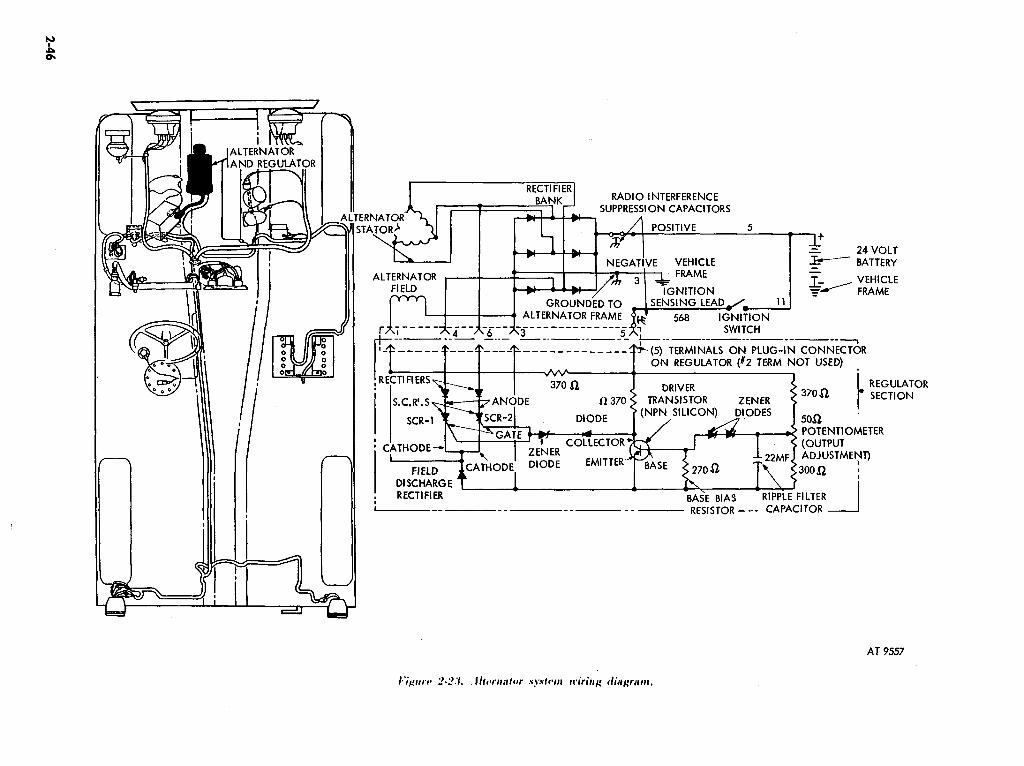
=J
1
24 VOLT BATTERY
A~~~~~~~~~~N HI --~rF~~E A__-___ -._- -_-- _--__ I__-__-__ -__-___
I;?-----r---r---T-------------TON (5) TERMINALS ON PLUG-IN CONNECTOR
REGULATOR (12 TERM NOT USED)
POTENTIOMETER
L__ __ ---__ ~ RESISTOR - -- CAPACITOR
AT 9557

DESCRIPTION:
Table 2-4. Electrical Troubleshooting-Continued
GENERATING SYSTEM CIRCUIT (Alternator) (fig. 2-231
The alternator system consists of a 60-ampere, 24-volt, negative ground alternator and internal voltage regulator and rectifier assembly. The circuit is energized by mechanical rotation of the alternator, which generates alternating current lacl. The alternating current is changed to direct current (dcl by the rectifier bank, and the output voltage is maintained at 28 ‘21 volts by the voltage regulator. This 28 volts is used to charge the vehicle battery and to assist the battery in carrying the electrical load of the vehicle. For further detailed information, refer to TM 9-2920-225-35 (Model 3002AA, group 41.
CAUTION The alternator is relatively new and unfamiliar to military vehicles. It is very important that the following precautions are obnerved to prevent damage to the alternator and regulator.
1. NEVER reverse the battery connections. ALWAYS check the battery connecting cables with a voltmeter before any attachments are made to he sure that the negative cable will be connected to the alternator frame and the positive cable to the alternator positive terminal. Reversal will immediately burn out the rectifiers, which cannot stand the reverse polarity.
2. Booster batteries for cold weather starting must also be properly connected. Make sure that the negative cable of the booster battery connects to the negative terminal of the vehicle battery, and the positive cable to the positive terminal. If in doubt. use a voltmeter to check. NEVER make a trial connection by “flashing” the cable.
3. ALWAYS disconnect the battery cables before connecting a fast charger to the battery.
4. NEVER use a fast charger for starting the engine. Use another battery or a booster made for the express purpose of starting engines.
5. NEVER disconnect the voltage regulator sensing lead (ignition lead No. 568) while the engine is running. This is the only information the regulator has on the battery voltage. If the lead is removed. the alternator will burn itself out trying to reach 28 volts.
6. NEVER ground the alternator output terminal. The internal resistance is very low and an external short circuit will overload all the regulating and generating circuits, resulting in nurn- out.
7. NEVER operate the alternator with the ignition sensing terminal energized unless a load is connect to the alternator output.
8. NEVER try to polarize an alternator. It is not necessary and could result in expensive damage.
0. NEVER disconnect batteries with .mgine running.
NOTE Start and run engine at fast idle until normal temperature is reached.
Malluactica
9. Alternator not charging. NOTE
Failure of the alternator usually results in discharged or overcharged batteries. If the batteries become discharged without obvious cause. the alternator mav be at fault. Quite often. failure of the alternatnr may be anticipated by observing the battery-generator indicator. Refer to pars 2-25a and figure 2-13 for correct in- terpretation.
Circuit
3.3..368
Test
Test 1. Make a visual inspection. Check belt tension (para 2-661. bearings. loose terminals on alternator. batteries and starter switch. Also look for frayed or broken wires. corrosion or. any other visible signs of damage. deterioration. or maladjustment. Make any required repairs before proceeding with further tests.
NOTE Test batteries for proper charge before further testing (para 2-2.51.
Test 2. Perform alternator output test. Start the engine and run it at 1000 to 2000 rpm for 15 minutes. Connect a voltmeter Imultimeterl from the alternator output terminal to the alternator ground terminal. as shown in f@krQ 2-24 test ?A. The voltmeter should indicate 28-t] volts. If the voltapr reading is less than 27 volts. stop the engine and note the voltage indicated. If the dtag~ reading remains the same as when the engine was running. disconnect the ignition sensing lead No. 568. Con,nect thy volt- meter from the alternator ground terminal to the end of the lead No. 568 from the ignition switch. as shown in test 2B. Turn on the ignition switch 1110 NOT START THE ENGINEI. The voltmeter should indicate 24i-,l volts. If the voltmeter indicates no or very low volts. repair or replace wire No . 508. and rete$t. If 24 volt* is now indicated. reconnect the ignition *nsina wire to the alternator ignition terminal.
2-47

VOLTMETER VOLTMETER ALTERNATOR AND REGULATOR
/
- TEST 2A
\
28 VOLTS
24 VOLTS I-
.T RANGE .T RA ,NGE
TEST 2. ALTERNATOR OUTPUT TEST
IGNITION SWITCH
ADJUST LOAD TO 4O.AMPS
START WITH LOAD SWITCH
OFF
/ & $ - -T I (;;)
: ‘I T+ I’ 50 VOLT RAVGE
VEHICLE FRAME
TEST 3. ALTERNATOR LOAD TEST
IGNIT\ON SWITCH
AT 9558

T&b Y-4. Electrical Troubleshooting-Continued
GENERATOR SYSTEM CIRCUIT !Alternator) (fig. 2-23)
Malfunction
0. Alternator not charging- Continued
circuit
3,5,568
5.6
3
Test
Repeat the alternator output test (above). If the alternator still has no output, replace the alternator with a known good one. If the alternator still has not output, replace the alternator with a known good one. If the alternator output is greater than 28.5 volts, or less than 27.5 -volts, remove
the plug from the front flange of the alternator. Adjust the output control until the voltmeter indicates exactly 28 volts. If the output voltage cannot be adjusted to this voltage, rep!ace the alternator with a known good one.
Test 3. Perform alternator load test. Connect the low voltage circuit tester as shown in figure 2-24, test 3. Be sure the voltmeter is on the SO-volt range, the ammeter on,the lOO-ampeie range, and the load bank switch in “OFF” position. Set the coarse load control to “OFF” or minimum coun- terclockwise position. Start the engine and run at 1000-2000 rpm. Set the load bank switch to “ON” position and adjust the load contiol until the ammeter indicates 40 amperes.
Note the voltmeter indication at this time. If the voltmeter indicates 27 volts or more, the alternator is operating satisfactorily. If the voltmeter indicates slightly less than 27 volts, remove the plug at the front of the alternator and adjust the output control to exactly 28 volts. If the voltmeter indicates less than 27 volts and cannot be raised to 28 volts, perform the cable tests.
Test 4. Perform alternator-to-battery cable test. Connect the low voltage circuit tester as shown in figure 2-25, test 4. Start the engine and run at 1000 to 2000 rpm for 15 minutes. Turn the load bank switch “ON” and adjust load bank control until 40 amperes is indicated on the ammeter. Connect the voltmeter from the alternator output TERMINAL STUD to the positive battery POST. Adjust the voltmeter range switch until a reading is obtained or the l-volt range is reached. If the meter reading exceeds 1.0 volt, turn off engine and examine all connections between the alternator and battery for loose connections, frayed wires and dirt. Clean and tighten all connections. Repeat the test. If the total voltage drop is still more than 1.0 volt, connect one voltmeter lead directly on the alternator terminal bolt, and successively touch each test point (alternator cable, starter switch, battery cable terminals). As each test point is touched, a small voltage drop af about 0.1 should be seen. If there is a sudden voltage jump at any connection touched, investigate the previous connection or cable. When a 1.0 volt or less drop has been obtained and the alternator output is still much less than 27 volts in test 3, perform the alternator ground cable test.
Test 5. Perform alternator ground cable test. Set up equipment as in test 4, above. Connect the voltmeter from the negative battery terminal (scraped well) to the ground terminal on the alternator. (Be sure to touch the ter- minal, not the cable end.) Start the engine and run at 1000 to 2000 rpm for 15 minutes. Adjust the load bank (as in test 4, above) for 40 amperes. The voltmeter should read less than 0.1 volt. If more, investigate and clean the alternator ground cable: Repeat test 3, above.
2-49

-
-
IGNITION SWITCH
TEST 4. ALTERNATOR-TO-BATTERY CABLE TEST
IGNITION SWITCH
ADJUST LOAD
TEST 5. ALTERNATOR GROUND CABLE TEST
AT 9559
I+rrrc* 2-25. Allrriator systrtn trsts.

Malfunction Circuit
7’;1biv P-C. k’lwtrical Troubl~slrootirrg-Continued
GKNEHATING SYSTEM CIRCUIT (Alternator) (fig. 2-23)
0. Altt~rtlator not cliargitig-
~htirtttcd
10. Alternator not charging, and battery discharges even if vehicle is not in use.
6.6X.7
5
Test
Test 6. Battery cable test. Refer to tests 3, 4, 5 and. 6 of Starting Tests, figures 2-18 and 2-19. When all cables have been tested and repaired (as required) repeat test 3, above. If the alternator output still cannot be ad- justed to 27.5 volts, replace the alternator with a known good one.
Test ‘i. Perform the rectifier integrity test. Be sure engine and ignition switch are “OFF”. Remove the cable from the alternator output terminal as shown in figure 2-26, test 7 A. Touch the cable to the terminal in a darkened area. If there is any indication of sparking, one or more rectifiers or the radio suppression filter is defective. If no sparks appear, connect the ammeter in the line as shown in figure Z-26, test 7 B. Touch ammeter test lead to the output terminal of the alternator. There should be no indication on the meter except a small jump at the moment of connection. If there is any meter indication, the alternator has internal leakage and will discharge the battery in a day or two, depending on the severity of the leakage. If the meter has an indication, replace the alternator with a known good one. If the meter has no indication. reinstall the cable and tighten securely.
2-51

ALTERNATOR
AND RE/GULAToR
TEST 7A. RECTIFIER
IGNITION SWITCH
IGNITION SWl;CH
IN1
WITH ENGINE OFF TOUCH LUG
TO TERMINAL AND CHECK FOR
SPARKS HERE TO STARTER
TERY POSITIVE
TO IGNITION
ALTERNAToR
.EGRITY CHECK (PRELIMiNARY TEST) NO METER
INDICATION
TEST 76. RECTIFIER INTEGRITY CHECK (METER TEST)
AT 9560

IGNITION SYSTEM CIRCUIT (fig. 2-27)
The ignition system produces and delivers high voltage surges to each spark plug in turn at correctly timed intel’vals relative to the respective piston position.
When the distributor contact points are closed, current flows from the battery through the ignition coil low voltage circuit, then through the closed contact points and back to the battery through ground. This is known as the primary circuit.
A ballast rrsistor is incorporated in series with the coil primary winding to reduce the primary current and prevent overheating of the coil. and to maintain a nearly constant current flow throughout the voltage range.
Standard automotive ignition systems would not function properly without a condenser. The condenser prevents arcing at the distributor contact points when they begin-to open, by providing a place for (1lrrent to flow until the &tints are safely separated.
W’IIW current flows through the primary circuit, a magnetic field is built up in the coil. As the circuit breakrr cam rotates. it opens the contact points and breaks the primary circuit. The magnetic energy is transformtd into a high voltage anrge (approximately 25,000 volts I sufficient to establish a spark at the spark plug gap
In addition 141 &sing and opening the contact points so that high voltage surges may be produced in the cr#ii. the igniter delivers these high voltage surges to the correct spark plug. at the correct instant. This is ac*ctm~piiahtd by thr rotor. cap’and high tension wiring and is known as the secondary circuit.
:\ pair of metal tubrs are c*onnrcted to the ipnitor assembly. one to the vacuum pump and the second to 111~ c.arlmrc.tor air intaktb. ‘I’ht~se I’ p~nt*ratcd by the t*lrctrical arcs.
lnes are necessary to keep the ipnitor purged of corrosive gases
CAUTIOlY If thc&;,urgr lirws are not in place, the igniter assembly will deteriorate rapidly.
I:!
I:!
‘l’tvt I. I’cbrform secondary circuit voltage test. Remove each spark plug ~~blt* from its spark plug. Crank the engine with the starter t ignition switch INI I wllilc holding he spark plug cable end one-fourth inch from cylinder Iwacl ax sl~own in figurc~ 2-27. test I. If a spark jumps the gap between the ~.irl)lc ;111d ht~~d. the spark plug is defective. dirty. or has incorrect electrode gap adjustment. If. after cleaning. adjusting. or replacing spark plugs. the h.ngint. still &WS IIOI start. clwrk the fuel system (para 2-42 I and distributor liming I para 2-Y I I. If a spark does not jump the gap. proceed with test 2.
I’VSI 2. I’t*rform l+nary c*irc.uit resistanre test. Connect adapters. jumper wire a@ \oltnit*tt*r a* shown in figurca 2-27. test 2. Select SO-volt range. I’ttrn on ignition rwitch. If the voltmeter ribow~ low or IN) reading. switch ~11~ \cJtmaqc*r rangcb st*lec*t~)r tt) a lower range until a reading is obtained or LIIV I-\ tilt rangt’ i* rt~ac*ht*cl. If voltmt.trr reads less than 0.2 volt. ignition 4~ itc.11 and Iwinl;rry &wit connwticm are normal. A reading of mortx than il.:! \c,lt inclic~att~+ it faulty ignition switch or primary circuit. Turn swi1c.b to ‘Y ,FF” ;111cl to "( bS" ~~*\t~ral timc*s. If mrtt.r indicates a different vcrltagc rlc+ ti~IIv .swit& i.s turned on. c*htBc*k for loo.stb or c*t#rrcBdrd c.onnPc.tiot,.~.
2-53

SPARK PLUGS
DISTRIBUTOR c T u CONDENSER
\V.~CLE/+ FRAME
TEST 1. SECONDARY CURRENT TEST
.2 VOLT OR LESS SELECT 50 VOLT
THEN SWITCH TO 1 VOLT RANGE
1 TEST 2. PRIMARY CIRCUIT RESISTANCE TEST AT 9561

Malfunction
13. Engine starts hard or stalls easily
14. Engine misfire at high speed and under load. or is hard to start.
1.5. Engine runs unevenly
Circuit
12
12
I 2
Teat
Test 3. Perform breaker point resistance test. Connect voltmeter and adapter as shown in Fig. 2.28. test 3. Select .X-volt range on voltmeter. ‘f’urn ignition switch to “ON” position. Actuate starter switch for short intervals until voltmeter reads zero. or very low value. Breaker points are now closed. Switch the voltmeter range selector to a lower range until a reading is obtained or the l-volt range is reached. A reading of less than 0.2 volt indicates that breaker points. internal primary connections and distributor ground are normal. A reading of mote than 0.2 volt indicates a poor distributor ground to engine or burned and pitted breaker points.
Test 4. Perform breaker point dwell test. Connect dwell meter and adapter as shown in figure 2-28. test 4. Set dwell meter selector switch to 4cylinder position. Start and operate engine at 600 tpm. Observe dwell meter. A reading of 3%44O indicates normal breaker point gap setting. A reading of mote than 44 degrees (small gap) may be a cause of hard starting. A reading r)f leas than 30° Igap too larget. may cause engine to misfire at high speeds or when pulling a heavy load.
NOTE Ignition timing must be checked whenever breaker point gap is adjusted.
Test .5. Perform dwell variation test. First. perform breaker point test shown in figure 1-18. test 4. Slowly increase engine speed from 600 rpm to I.?oo rpm and observe the highest and lowest dwell indication on dwell mrter. :\ variation of less than 3” indicates distributor shaft and bushing are within specification. If a satiation of more than 3 degrees is noted. chec*k breaker point spring tension and possible binding of moveable point on its pivot prior to declaring distributor faulty.
2-55

.2 VOLT OR LESS
68 1 BATTERY PRIMARY $
SELECT 5() VOLT RANGE FIRST 4. THEN SWITCH TO I VOLT RANGE
/ ON SWITCH +
ADAPl ‘ER
TEST 3. BREAKER POINT RESISTANCE TEST
VEtii?LE FRAME
39-44 DEGREES
600 RPM
TEST 5. DWELL VAilATlON TEST
AT 9562

Malfunction
16. Engine has spark knock on hard pull, overheating, hard starting, lack of power.
1 i. Engine runs unevenly, misfires at high speed, spark knock on hard pull.
circuit
6.i.12.6X
6.7,12.68
Test
Test 6. Perform ignition timing test. Clean crankshaft timing notch and pointer (fig. 2-201. Connect techometer and adapter as shown in figure 2- 28:test 4. Connect adapter and timing light as shown in fig. 2-29, tests 6 and 1. Start engine and set idle speed at or below 500 rpm. Timing notch alined with pointer indicates ignition timing is in correct adjustment. Timing notch above pointer or below pointer indicates incorrect ad- justment.
Test 7. Perform ignition timing advance test. Connect tachometer, adapter and timing light as shown for test 6, above. Start and operate engine at 500 rpm. Use timing light to observe timing notch and slowly increase engine speed to 1500 rpm. Hold engine speed at 1500 rpm and observe timing notch. If timing notch moves from pointer, distributor governor mechanism is operating normally. If timing notch does not move or jumps from pointer, distributor is faulty. If timing notch moves back and forth when engine speed is held constant. replace distributor and repeat test. If timing mark still moves back and forth, engine timing gears may be worn. Notify direct support maintenance unit.
2-57

BATTERY
TIMING LlGHT
VEHICLE FRAME
LEAD FOR 12-VOLT
TIMING LIGHT MAD ApTER
LEAD FOR 24-VOLT
TIMING LIGHT TEST 6. IGNITION TIMING TEST TEST 7. IGNITION TIMING ADVANCE TEST
AT 9563

I LIGHTING SYSTEM CIRCUIT (fia; 2-301
DESCRIPTION : Light circuits are controlled by the light switch on the instrument panel. Each light is connected to the light switch by connectors, wiring harnesses and cables: cables are identified by numbered tags near the end of each cable. A circuit breaker in the light switch protects the lighting system from overload. The lighting system is waterproofed.
The light circuits are energized from the battery through circuits 6. 5 and 15. Individual or groups of lights are selected by the light switch, except the stoplamp, which is energized by, a hydraulically- operated switch in the brake hydraulic system, and the directional signal system, which has an in- dividual actuator / selector on the steering column. To test the operation of the lighting system, refer to TM 9-2320-218-10 for operating instructions for the light switch.
NOTE on MlSlA2, M825, and M718Al vehicles the stoplight is operated by an electro-mechanical switch which is attached to the brake pedal support, and is activated when force is applied to
I
brake pedal.
Malfunction
18. Generally unsatisfactory lighting (flickering, dim, frequent burnouts, intermittent)
clhxit
65.15. 1;,1x.91 21,22,X! 24
NOTE Before attempting to troubleshoot the lighting system, refer to the TM 9-2320-218-10 to become familiar with the lighting arrangement for each switch position and the nomenclature for each light.
Test 1. Perform a visual inspection. Inspect connections at the light switch and each individual light. Inspect all ground connections at light assem- blies. If grounds are rusty or dirty. remove ground wire, scrape metal until clean, and reconnect. tightening securely. After tightening, coat the area with grease or other rust-reducing compound. If the complaint is short lamp life, or frequent burnout of lamps. check for high generating system voltage (refer to figs. 2-20 or 2-241. or loose lamp housings or components that would cause excessive vibration. Before discarding a lamp that has been removed, test it in another known good light socket or with an ohmmeter, to determine whether the lamp or socket is at fault.
2-59

EST 2A.
SER. DRIVE POSITION
VOLTAGE
WIRE NO. 1 CIRCUIT
17
I HIGH BEAM
18 LOW BEAM 91 - _ 1 GROUND
TEST 28. HEADLAMP RESiSTANCE TEST %
18 1 LOWBEAM
16
SER. DRIVE POSlilON
TEST 3. DIMMER SWITCH TEST
AT 9564

7*&h 2-4. Ekctrical ‘I’roublr?shooting-Continuad
LIGHTING SYSTEM CIRCUIT (fig. 2-3fll
9. Headlight (one side) inoperative.
20. Headlights (both sides 1 inoperative.
21. Blackout and marker lights inoperative.
Circuit
17.1&91
16.17,18
19.20 91.491
Test
NOTE The following voltage tests may be performed with either the multimeter. or the voltmeter section of the low voltage circuit tester.
Test 2. Perform service headlamp connector voltage test. Disconnect connector and connect voltmeter as shown in figure Z-30, test 2A. Turn lighting switch to “SER DRIVE” position. If no vohage is indicated, operate dimmer switch. If 24 volts is indicated, make a resistance test of the lamp unit. If not reading is indicated, in either position of the dimmer switch, and the other beam of the headlight operates, the wiring harness for headlamp to dimmer switch is unserviceable. Turn light switch to “OFF”. Connect the multimeter between lamp terminals 91 and 18. as shown in figure Z-30, test 2B. If the multimeter needle moves past the center of the scale. connect the leads between terminals 91 and 17, and repeat. If the needle does not move with either test. replace the lamp with a known good one. If replacement lamp unit does not light, pin connector of headlamp body may be faulty.
Test 3. Perform service headlamp voltage test (both sidest. Check for voltage at connectors of both lamps as in test 2. If voltage is not present, disconnect No. 17 and No. 18 wires at dimmer switch. Connect voltmeter as shown in figure Z-30, test,3. Check for voltage at exposed terminal No. 17 of the dimmer switch. If voltage is not present, actuate switch. Repeat this step for exposed terminal No. 18 of the dimmer switch. If 24-volt reading is indicated at No. 17 and No. 18 switch terminals, but not at headlamp connectors, wiring harness from headlamps to dimmer switch is unserviceable. If voltage readings are not present at No. 17 and No. 18 dimmer switch terminals, remove No. 16 wire and connect the positive lead of the voltmeter to the No. 16 wire (not the dimmer switch terminal), to see if supply voltage is present. If voltage is indicated, replace dimmer switch ; if no voltage is indicated, perform lighting switch connector voltage test Ifig. 2-33, test 91 to determine if lighting harness from dimmer switch,to lighting Witch is unserviceable.
Test 4. Perform front blackout lamp connector voltage test. Connect voltmeter as shown in fig. 2-31, test 4. Turn lighting switch to “BO DRIVE” position. If 24 to 28 volts in indicated, replace bulb; ff new bulb does not light. check for corroded, dirty or defective socket and wire assembly. If no reading is indicated, perform lighting switch connector voltage test (fig. 2-33, test 91 to determine if wiring harness is un- serviceable.
NOTE See figure 2-31 for illustration of above test 4 procedures on M151A2. M82.5. and M718Al vehicles.
2-61

WIRE NO *I
CIRCUIT
I9
I
B.O. DRIVE 20 8.0. MARKER 91 GROUND
M151A2, M718Al AND MB25
8.0. DRIVE POSITION
M151, M151Al. M151AlC AND M71B
TEST 4. FRONT BLACKOUT LAMP CONNECTOR VOLTAGE TEST
23 -
24
21 22-461 -
6%
23
24
AT24148
B.O. STOPLIGHT 6.0. REAR MARKER
MUST BE IN POSITION FOR
LAMPS BEING TESTED
M151AZ,M71BAl ANDMB25
TEST 5. REAR IAMP CONNECTOR VOLTAGE TEST
bYgtcrc 2-31. I,ighting system tests.
461
M151, M151Al. Ml51AlC AND M71B
AT 39842

22. Rear lights inoperative.
23. One or more trailer lights ou (Trailer receptacle inoperative).
24. Rear lamps inoperative (test ta determine if cause of failure is lighting switch or wiring harness).
7’ablc .2-4. Electrical Troubleshooting-Continued
LIGHTING SYSTEM CIRCUIT (fig. 2-301
Circuit
21. 22. 23. 24
21, 22. 23. 24A. 24% 90. 490
21. 22. 23, 24. 28. 77 IMl31. Ml.SlAl. & Mi18 vehs. only I 21, 22. 23. 24. tMlSlA2 M825. & MTl8A.l vehs.
Test
Test 5. Perform rear lamp connector voltage test. Connect the voltmeter as shown in figure 2-31, test 5. Turn lighting switch to position corresponding to position of faulty rear lamp: if stoplight, depress brake pedal. If 24 to 28 volts is indicated, replace bulb: if new bulb does not light, check-for corroded, dirty or defective socket and wire assembly. If no voltage reading is indicated, perform lighting switch connector voltage test (fig. 2-33, test 9 I to determine if wiring harness is unserviceable.
Test 6. Perform trailer connector voltage test. Turn lighting switch to position which should light inoperative trailer lamp. Connect voltmeter as shown in figure 2-32, test 6, to appropriate connector socket of inoperative circuit. If 24 to 28 volts is indicated at correct connector socket, check the No. 90 wire ground connection. If No. 90 wire is tightly grounded, trailer electrical system is faulty. If no reading is indicated at correct connector socket. perform chassis harness connector voltage test (test, 7 below 1.
Test 7. Perform chassis harness connector voltage test. Remove rear chassis harness connectors. Connect voltmeter as shown in figure 2-32, test 7, to appropriate connector socket for inoperative circuit. Turn light switch to position which should light faulty lamp; if stoplight is the inoperativg; circuit. depress brake pedal. If 24 to 28 volts is indicated check rear harness from rear chassis connector to inoperative lamp for broken or chafed wires. 3f no reading is indicated for blackout marker or service lamp connector terminals. perform lighting switch voltage test (fig. 2-33. test 91. If no reading for stoplight circuit terminals (brake pedal depressed with lighting switch in correct positionl. perform stoplight switch test (fig. 2-33. test 81.
2-63

: NNECTORS
:I
WIRE NO. CIRCUIT (E7)
21 22-460 22-461
23 24 77
SERVICE REAR LIGHT SERVICE STOPLIGHT (RH) SERVICE STOPLIGHT (LH) 6.0. STOPLIGHT B.O. MARKER LIGHTS I FUEL PUMP
TO FRAME
_Plh I t
24A 22-461
248 90 21 23
490 22-460 NONE
90 NONE NONE
REAR B.O. MARKER (Cl-l) SERVICE STOPLIGHT (LH) REAR B.O. MARKER (RH) GROUND TO FRAME SERVICE REAR LIGHT B.O. STOPLIGHT 8.0. MARKER LIGHTS SERVICE STOPLIGHT (RH) NOT USED GROUND TO FRAME NOT USED NOT USED
E. REFER TO TRAILER MANUAL FOR TYPE AND
TEST 6. TRAILER CONNECTOR VOLTA
WIRE NO,
Y
MUST BE IN POSITION FOR
I IP_“TC IIElhlr- TFCTFI, a
CIRCUIT d (TEST 6)
NOTE: SEE WIRE TABLE An*,,!z 1 CCT
/ VEHICLE
TO REAR OF VEHICLE‘ TEST 7. REAR HARNESS CONNECTOR VOLTAGE TEST -~ AT 9566.
Figure 2-32. Lighting sys:em tests.

/ ELECTRO-MECHANICAL
STOPLIGHT SWITCH JUMPER FROM
24-VOLT TERMINAL
/
HYDRAULIC STOPLIGHT SWITCH
TO VEHICLE FRAME
M151i?, MB25 AND M7lBAl
STOPLIGHT S!.‘flTCH PANEL LIGHTS SERVICE STOPLIGHTS 8.0. DRIVING LIGHT 8.0. MARKER LIGHTS BATTERY POS. 24 VOLTS SERVICE REAR LIGHTS DIRECTIONAL INDICATOR STOPLIGHT SWITCH PARKING LIGHT StRVlCE HEADLIGHTS 8.0. STOPLIGHT
MlSlA2, MB25 AND M71BAl
LIGHT SWITCH IN STOPLIGHT
POSITION
TEST 8. STOPLIGHT SWITCH VOLTAGE TEST
CONNECT JUMPER FROM “F” TO
DC FAULTY CIRCUIT
50 VOLT RANGE
TO VEHICLE FRAME
TO VTHICLE
FRAME
Fi~rrrr 2-33. Lighting system tests.
SOCKET NO. WIRE
A
5 D
E F H J K L M N
75 STOPLIGHT SWITCH 40 PANEL LIGHTS 22 SERVICE STOPLIGHTS I9 B.O. DRIVING LIGHT 20 0.0. WRKER LIGHTS. I5 BATTERY PO% 24 VOLTS 21 SERVICE REAR LIGHTS
440-46 1 DIRECTIONAL INDICATOR 75 STOPLIGHT SWITCH
NONE NOT USED I6 SERVICE HEADLIGHTS 23 8.0. STOPLIGHT
CIRCUIT
M151. M151Al. MlSlAlC AND M71B
AT 39837

Tabk 2-4. Electrical Troubleshooting-Continued
LIGHTING SYSTEM CIRCUIT (fig. 2-301
25. Stoplight inoperative (stoplight switch test 1.
26. Lamps will not light (some lamps will not iightl. -
DESCRIPTION :
ciiuit
75
Test
NOTE Electrical wire connection No. 77 shown in test 7 of figure 2-32 is for the electrical fuel pump. MlSlA2, M825, and M718Al vehicles do not have this wire.
Test 8. Perform stoplight switch voltage test. Move lighting switch to “STOPLIGHT” position. Disconnect connector from the stoplight switch located under the cowl panel on the bottom of the master cylinder assembly. Connect voltmeter as shown in fife 2-33, test 8. Check for voltage,at one of the two No. 75 wires. If voltage is indicated, jumper that wire to one terminal of the stoplight switch. With brake pedal depressed, use positive voltmeter lead to check for voltage at exposed stoplight switch terminal. If 24 to 28 volts is indicated, stoplight switch is serviceable. If no reading is indicated at either of the two No. 75 wires, perform lighting switch con- nector voltage test (test 91 to determine if wiring harness is broken or if lighting switch is unserviceable.
NOTE See figure 2-33 for an illustration of above test 8 procedures for the electro-mechanical stoplight switch on M151A2, M825, and M718Al vehicles.
15, 16, 19, Test 9. Perform lighting switch connector voltage test. Remove liihtfng 20, 21, 22 switch from dash panel and disconnect harness connector. Connect volt- 23, 40, 75, meter between vehicle frame and socket (F) of lighting switch harness as 460, 461 shown in figure 2-33, test 9. If 24 to 28 volts is not indicated, check wiring
harness circuits Nos. 5 and 16 from starter to lighting switch for broken wires or loose connections. If 24 to 28 volts is indicated on socket (F) of the connector, connect a jumper wire from (F 1 socket to socket of faulty circuit. If lamps light with jumper wire connected, replace lfghting switch. If some lamps do not light with jumper wire connected, check wiring harness from lighting switch to’inoperative light or rear harness connector for broken wire,
DIRECTIONAL SIGNAL SYSTEM CIRCUIT (fig. 2-341
Two types of directional signals are in use on these vehicles. Early production vehicles are equipped with a mechanical system, and later production vehicles use a solid state (transfstorizedl system. The mechanical system is considered obsolete and will not be covered in detail in this manual. The solid state system consists of a directional signal control assembly (mounted on the steering columnl, a flasher unit, connecting cables. and four lamps. The two front lamps are individual units. The rear lamps are combined with the service stoplights. The system is energized by setting the light switch to “STOPLIGHT” position, which supplies 24 volts via wire 460-461 to terminal “G” of the directional signal control unit. Moving the control unit lever to indicate a left turn connects terminal “G” to ter- minal “F” and supplies 24 volts to the flasher unit. At the same time, it connects the output of the flasher to the left front trun indicator light and the left rear stoplight, and activates the control uuit indicator lamp. The hydraulic stoplight switch is also disconnected from the left rear stoplight to prevent it from overriding the flasher unit. The right rear stoplight remains connected to the hydraulic stoplight switch and operates normally when the brakes are applied. Moving the directional signal control lever to indicate a right turn causes the same action to occur on the right hand side of the vehicle. Moving the directional signal control lever to “FLARE” position connects all four lights ftbe two front turn in- dicators and the two stoplights) to the output of the flasher unit and disconnects hydraulic stoplight switch from both stoplights. An overall test of the system is to perform all functions of the directional signal control switch and observe the action of the lights as described above. Figure 2-34 shows a wiring diagram of the complete system circuit.
2-66

460-461
TO BATTERY e
LIGHT r SWITCH
(M151, M151Al. Ml
(M151A2, M825 AND M718) B
H
FRONT TURN SIGNAL
LIGHTS
(M151, M151A1, M151AlC AND M7 18)
SERVICE STOPLIGHT
T RH 4
SOLID STATE DIRECTIONAL SIGNAL SYSTEM - WIRING DIAGRAM f SERVICE
MULTIMETER STOPLIGHT
TEST 1. LAMP CONTINUITY TEST
SERVICE r=1 STOPLIG.HTS
(M151A2, M718Al AND M825)
22-460 OR 22-46 I
STOPLIGHTS
(M151, M151A1, M15lAlC AND M718)
AT 3984 1
ICgrcrc 2-N. Directional signal system tests.

DESCRIPTION Continued
Teble 2-4. Eicctrical Troubleshooting-Continued
DIRECTIONAL SIGNAL SYSTEM CIRCUIT (fig. 2-34)
tMlSlA2, M825, and M718Al): The solid state directional signal system on the above vehicles consists of a directional signal control assembly (mounted on vehicle’s steering column ), a flasher unit, the connecting cables, and the four signal lamps, two lamps at the front of the vehicle and two at the rear. Each front signal lamp is combined with a parking lamp and a blackout marker lamp to form one complete lighting unit. Each rear signal lamp is combined with a service taillight, a blackout marker lamp. and a blackout stoplight lamp into one complete lighting unit (fig. 2-34). In addition, the rear signal bulb functions as the service stoplight. The system is energized by setting the light switch to “STOPLIGHT” position which supplies 24 volts via No. 67 wire to terminal “G” of the directional control unit. Moving the control unit lever either up or down indicates either a right or left turn is being made, and activates the flasher unit and turn signal lamps at front and rear. At the same time, the stoplight switch on the side the turn is being made is disconnected so it will not override the flasher unit. Rut the stoplight switch on the opposite side of the vehicle is till connected, so this switch will activate the stoplight when the brake is applied and warn traffic in the rear that a vehicular stop is being made. Move the directional control unit lever into the “HAZARD WARNING” position connects all four
.directiona!lights (front and rear) to the output of the flasher unit and-at-the same time disconnects both the stoplight switches from both rear stoplight lamps. An overall test of the directional cucuit system can be made by performing all the functions mentioned above with the control unit lever and observing what happens.
NOTE If the vehicle is equipped with a mechanical flasher system, troubleshooting should be limited to a lamp check i test 1, below) and visual inspection for loose connections, poor ground, or frayed cables. If defects are found which cannot be corrected by minor repair, replace both mechanical units with the solid state flasher repair kit (see TM 9-2320-218-2OPl. Do not make a partial replacement: replace both mechanical flasher units with the complete solid state kit.
27. Individual lamps do not light 460. 461 with directional signal control lever in 22-460. any position. 22-46 1
24
circuit
460. 46 1. Z-460. 22-46 I
Test
Test 1. Perform lamp continuity test. Set main light switch to “STOPIJGHT” Position. Trv all nositions of directional signal control lever. and observe which lights do not light in any position of the lever. Have assistant depress brake pedal and observe stoplights. If stoplights light. rear lamps are operational. If stoplights do not light, or if front turn indicators do not light in any position of the control lever, turn light switch to “OFF” and disconnect connector 460, 461, 22-460 or 22-461, as required (fig . Z-341. Set up multimeter for continuity test (fig. 2-13 1. Touch red lead to connector on light, as shown in figure 2-34. test 1. If the meter needle deflects to approximately 5 ohms. the lamp is normal and the trouble is elsewhere. If the meter does not deflect at all (infinity reading) replace lamp with a.known good one, and retest. If meter still shows infinity or considerably more than 5 ohms, touch red test lead to the lamp housing, making sure to scrape through the paint to the bare metal. If the meter does not deflect completely to xero ohms. inspect the ground connection. removing the ground wire and scraping all metal surfaces brighi. and reconnect. When light has been restored to 5 ohms, reconnect the connector and test the directional system again. If trouble still exists. perform wire harness tests.
Test 2. Perform wiring harness voltage test. Set up multimeter for dc voltage tests (see fig. 2-l 11. Disconnect connectors 460. 461. 22-460 or 2% 461. as required lsee diagram. fig. 2-341. Set main light switch to ” “STOPLIGHT” position. and directional signal control lever to “FLARE” position. Connect multimeter as shown in figure 2-3.5. test 2. Touch red test lead to renter contact of cable connector on wiring harness. The voltmeter needle should defect past 24 volts at a rate of I to 2 per second. If meter does not deflect. or deflects much less than 24 volts. leave connector disconnected from light and perform wiring harness continuity test.
NOTE Before starting test 2 procedures on M151A2. M82.5. and MYl8Al vehicles. set directional control lever to “HAZARD %ARNlNG” position. Connect multimeter as shown in figure 2- 3.3. test 2. Disregard wiring for parking and blackout marker lamps (wires No. 20 and No. 491 1. and test only front directional signal wires No. 460 and /or No. 461 as indicated in figure 2-3.5. Proceed with test 2. Figures Z-30 and 2-37 also illustrate the new directional turn signal design on M 13 I AZ. M82.5. and MY 18A 1 models.

27..Individual lamps do not lighl 460, 461 with directional signal control lever in 22-460 any position-Continued 22-461
Tabh 2-4. Elcctrical Troubleshooting-continued
DIRECTIONAL SIGNAL SYSTEM CIRCUIT (fig. 2-341
Test 3. Perform wiring harness continuity test. Set up multimeter for continuity test (fig. 2-13). Set main light switch to “OFF”. Connect the black test lead to the vehicle frame near the control unit. Remove the cable connector from the control unit. Touch the red test lead to a socket in the cable connector to correspond with the defective circuit. The meter needle should not deflect (infinite reading). If there is any defl&tion, the wiring harness has a short circuit, or a high resistance leakage. Inspect the harness for frayed or pinched cables, and make repairs. If infinity is indicated on the. meter. connect a jumper wire from the ,vehicle frame to the cable connector at the light, as shown in fife 2-35, test 3. Touch the red test lead to the appropriate socket terminal in the cable connector at the control unit. The meter needle should deflect fully. showing zero ohms. If less than full deflection. inspect the wiring harness for breaks, frayed wires, corroded cqmnections. etc., and make necessary repairs. When all lamps and wiring harness have continuity restored, and system still does not operate, perform flasher and control unit tests.
2-69

M151, M151Al. M151AlC AND M718
p F
FRONT
M151A2, M825 AND M718Al n/ HAZARD WARNING POSITION
D T
FRONT
STOPLIGHT POSITION
~ 22-460
2 22-460
22-461 ?
(M151, MlSlAl, M
M151, M151A1, MlSlAlC (M151A2, M825 AND M718Al) CONTROL AND M718 UNIT
M151A2, M825 AND M718Al
M151, M151Al. MlSlAlC AND M718
RH
?
LH
ts T
RH
CONNECT JUMPER
LH
TEST 3. WIRING HARNESS CONTINUITY TESTS
22-
RH
OPiN TEST: CONNECT JUMPER
LH
SHORT TEST: JUMPER OFF
m151AlC
AT 39840
Malfunction
28. No lights operate with dire tional signal control lever in 81 position.
‘I’&le 2-4. E[ectricai Troubieshooting-Continued
1)IRECTIONAL SIGNAL SYSTEM CIRCUIT (fig. 2.34)
circuit
460, 461
A, B, C
Test
Test 4. Perform directional signal control unit voltage feed test. Set up the multimeter for dc voltage test (fig. 2-11). Remove the cable connector from the directional signal control unit. Set the main light switch to “STOPLIGHT” position. Measure the voltage from the vehicle frame to terminal “G” of the cable connector on the wiring harness, as shown in figure Z-36, test 4. The meter needle should indicate 24 volts. If less or none, remove the cable connector from the light switch and perform a continuity test from contact “G” on the control unit end to contact “J” at the light switch end. If continuity is satisfactory, the light switch is d&ective. When 24 volts has been restored to contact “G” of the directional control unit cable connector, and the system still does not operate, perform the flasher cable continuity test.
Test 5. Flasher unit cable continuity test. Set up the multimeter for con- tinuity (fig. 2-13). Remove the cable connector from the flasher unit. Remove the cable connector from the control unit. Measure continuity between the cable wires as shown in figure 2-36, test 5. If any wire does not have continuity, inspect and make necessary repairs. If all three wires have continuity, perform the flasher operational test.
2-71

TEST 4. CONTROL UNIT VOLTAGE FEED TEST..
OFF
TEST 5. FLASHER UNIT CABLE CONTINUITY TEST.
MS 35478-1683 LAMP
TEST 6. FLASHER OPERATIONAL TEST
AT 39838 8 ,
Figure 2-36. Directional signal system tests.
2-72

Tahlr 2-4. Electrical Troubleshooting-Conrinued
DIRECTIONAL SIGNAL SYSTEM CIRCUIT (figure 2-341
Malfunction
29. Flashes erratically, no flash, OI very slow flash.
30. System operates incorrectly in one or more positions of the direc- tional signal control lever (all lights
and wiring harness test satisfactory)
Circuit
A, B, C
22, 22-460, 22-461, 460, 461, 75
Test
NOTE It may be necessary to remove the flasher from the vehicle to make the following test.
Test 6. Perform the flasher operational test. Disconnect the cable con- nector from the flasher. Connect a source of positive 24 volts to terminal “B” of the flasher socket. (If the voltage is inadvertently reversed to the flasher, it will not operate. However, the flasher will not be harmed due to built-in reversal protection.) Connect one lamp type MS-35478-1683 between contact “A” and “C”. Connect contact “C” to negative 24 volts, as shown in figure 2-36, test 6. The flasher should flash at a rate of 60 to 120 flashes per minute, at a regular rate without skipping. If it does not flash, or flashes irregularly, replace the entire flasher unit with a known good one. If the flasher tests satisfactory, perform control unit bench test.
NOTE It may be necessary to remove the directional signal control unit from the vehicle to perform the following test.
Test 7. Perform the directional signal control unit continuity test. Set up the multimeter for continuity tests (fig. 2-131. Remove the cable connector from the control unit, and if necessary, remove the control unit from the vehicle. Set the control lever in all four operating positions and make tests as shown in figure 2-3i, test 7. If any circuit does not test as shown in the tables, replace the control unit with a known good one.
2-73

SCHEMATIC DlAGRAM FROM PIN: TO PIN: INDICATION
NEUTRAL POSITION
A. DIRECTIONAL SIGNAL CONTROL LEVER IN “NEUTRAL”
OPEN OPEN OPEN OPEN SHORTED SHORTED OPEN
POSITION
SHORTED SHORTED OPEN OPEN SHORTED SHORTED OPEN
1, LEFT TURN T POSITION
B. DIRECTIONAL SIGNAL CONTROL LEVER IN “LEFT TURN” POSITION
F G SHORTED H A SHORTED H E SHORTED H B OPEN H C OPEN D C SHORTED D E OPEN
F POSITION
. C. DIRECTIONAL SIGNAL CONTROL LEVER IN “RIGHT TURN” POSITION
I H H H H D D F
? D. DIRECTIONAL SIGNAL CONTROL LE\, ‘ER IN “FLARE: POSI TION
TEST 7. DIRECTIONAL SIGNAL CONTROL UNIT CONTINUITY TESTS
A . B C E E C G
SHORTED SHORTED SHORTED SHORTED OPEN OPEN SHORTED
AT 39839
Figure Z-37. Directional signal system tests.
2-74

DESCRIPTION :
INSTRUMENTS. GAGES AND HORN SYSTEM CIRCUITS (fig. 2-38)
The battery-generator indicator, fuel level gage. temperature indicator. oil pressure indicator. headlight beam indicator and panel lights are mounted in the instrument panel. The fuel level sending unit is mounted in the top of the fuel tank and activates fuel level gage. The oil pressure sending unit and fuel pump safety switch (oil pressure safety switch1 are located at the oil filter mounting base IMlSlA2. M825. and M718Al vehicles have no fuel pump safety switch).
The temperature sending unit is located on the rear of the engine block. The horn switch is located in the steering wheel hub and activates the horn, mounted on the engine compartment firewall. The in- strument panel is energized by turning the ignition switch to “ON” position. This energizes circuit 27 from circuits 6. 5 and 11. Circuit 27 goes through a circuit breaker and then to the instrument panel. where it supplies 24 volts battery voltage for the various instrument and gage circuits. The temperature indicator system starts at the vehicle frame. through the temperature sending unit, via circuit 33 through the temperature indicator. to circuit 27. The oil pressure system starts at the vehicle frame. through the oil pressure sending unit. via circuit 36, through the oil pressure indicator, to circuit 27. The fuel level indicator system starts at the vehicle frame, through the fuel level sending unit, via circuit 28, through the fuel le&Lindicator, to circuit 27. The battery-generator indicator is connected from the instrument panel ground via~circuit 27B to circuit 2 i, thus putting it directly across the 24-volt battery suppl,y to the instrument panel. The instrument panel lamps are connected from the instrument panel ground via circuit 40 to the main light switch The high beam indicator lamp is connected from the instiument panel ground via circuit 17 to the high beam<.erminal of the dimmer switch. The horn is energized via circuit .5.25 through a circuit breaker. through tlm-horn assembly. through the horn button, to the vehi- cle frame.
2-75

WIRE NO. CIRCUIT
27 24 VOLTS FEED 278 BAti.-GEN. INDICATOR 28 TO FUEL GAGE
I FRAME SENDING UNIT
33 TO TEMP. GAGE
SENDING UNIT TO OIL PRESS. GAGE
BRtnhcn> -- LENDING UNIT ,
FUEL PUMP
M151, MlSlAl, MlSlAlC AN,D M7 18 ONLY
TRUMENT PANEL f 1
TEST 1. INDICATOR SYSTEM VOLTAGE TEST
BOTH TESTS ,
TEST 2. ONE GAGE INOPERATIVE
AT 39836
2-76
-- -_
‘I’;I 1110 :‘-A I:‘lec~trical~l rcruhl?shootinc-Continued
INSTRUMENTS. GAGES AND HORN SYSTEM CIRCUITS (fig. 2-38)
Malfunction
31. All gages inoperative.
32. One gage inoperative.
33. Oil pressure gage inoperative Isending unit test).
Circuit
27. 2 8. 33. 30
“7. 28. 33. 30
30
Test
NdTE When instrument panel is removed from dash panel. connect a jumper wire from instrument panel to vehicle frame to provide a return circuit for the indicator lights and the gage actuators.
Test 1. Perform indicator system voltage test. Remove and ground in- strument panel. Disconnetino. 27 wire at instrument. Turn ignition switch to “ON” position. Set up multimeter, for voltage tests (fig. 2-11) and connect voltmeter as shown in figure 2-38, test 1. If 24 volts is not in- dicated. test No. 27 wire at instrument panel circuit breaker. If voltage is indicated, check for loose connection or.faulty circuit breaker. If no reading is indicated at No. 2’i wire to circuit breaker, remove No. 27 wire from ignition switch. Connect meter to exposed pin of ignition switch. If voltage is indicated, check wiring harness between ignition switch and circuit breaker for loose connection or open circuit. Repair or replace if required. If voltage is not indicated at exposed pin, remove No. 11 wire from ignition switch and place probe on wire. If voltage is present, replace ignition switch. If voltage is not present, check main wiring harness for open circuit or loose connection.
Test 2. Perform individual gage voltage test. remove wire and connector from inoperative gage. Set up multimeter for voltage tests (fig. 2-11) and connect voltmeter negative lead to vehicle frame. Connect voltmeter positive lead to terminal of gage, as shown in figure 2-38, test 2. Turn ignition to “ON” position and observe reading. If reading is 3 to 4 volts for fuel level gage and oil pressure gage circuit of 24 volts for temperature gage. perform sending unit resistance test. If no reading is indicated, check gage wire and connector for breaks or loose connections. If satisfactory, gage is faulty.
NOTE Tdst 2 is useful for troubleshooting only a completely inoperative gage. For a complete test procedure, including accuracy tests. refer to TB %23OO-228-20 and TB ORD 434.
Test 3. Perform oil-pressure sending-unit resistance test. Disconnect No. 36 wire from oil pressure sending unit. Set up multimeter for resistance tests Ifig. 2-121 and connect it as shown in fig. 2-39. test 3. Start and operate engine at high idle speed. Ohmmeter reading should be less than 1 ohm before engine is started. and rise to about 6 to 10 ohms for normal oil pressures. Refer to conversion table in test 3, for a conversion of resistance values to pressures. If sending unit has more than 1 ohm resistance with engine “OFF” or considerably different resistances than shown in the table. sending unit is faulty. If resistance agrees with table. shut off engine and connect voltmeter to wire no. 36 as shown in figure 3-29, test 3. Turn on ignition switch. Voltage should read 0 to 2 volts. If less, or no voltage, check main wiring harness (wire No. 36) for open circuit or loose connection. If more, perform test 2, above, to check for faulty gage.
2-77

CONVERSION TABLE
AGF AND SFNDING UNIT TEST _._ . ..___ -.._ _..__... ._ __. ._.. .- -. .--- 0 OTOl 10 4.5 to 6
TEST 3.
BOTH DC
TESTS
DC
15 6 to 8.5 20 8.5 to 11
I 25 11 to 13.5 30 14 to 16
, 2 ;;.:,t;;”
b I ~,TEMpFRATIIRF SFNIYNG IlNlT
TEST 4. TEMPERATURE GAGE AND SENDING UNIT TEST
CONVERSION TABLE
-
AT 9573

34. Temperature gage inoperative (sending unit test).
35. Fuel level gage inoperative (sending unit test).
36. Battery-generator indicator inoperative.
33
28
2;
Test
Test 4. Perform temperature sending unit resistance test. Remove radiator filler cap and insert a test thermometer into coolant. Start and operate en- gine until thermometer temperature is stable. Disconnect No. 33 wire from temperature sending unit. Set up multimeter for resistance tests (fig. 2-12) and connect it as shown in figure 2-39, test 4. Refer the ohmmeter reading to the conversion table in test r. and compare the temperature to the test thermometer reading. Stop the engine and observe the ohmmeter reading as the radiator cools. The resistance should increase as the engine cools off, to a maximum of approximately 3000 ohms, depending on adjacent air temperature. If hot resistance differs considerably, sending unit is faulty. If resistance agrees with table. connect voltmeter to No. 33 wire as shown in figure 2-39. test 4. Turn on ignition switch. Voltage should read 24 volts. If much less, or no voltage, check main wiring harness (wire no. 33) for open circuit or loose connections.
CAUTION Be very careful when making electrical tests near the fuel tank. When components are removed. cover the tank opening with tape and make electrical tests as far from this area as possible.
Test 3. Perform fuel level sending unit test. Remove sending unit from fuel tank. Set up multimeter for resistance test (fig. 2-12) and connect as shown in figure Z-40. test 5. lMove sending unit float from bottom to top. An uneven increase in resistance or erratic meter needle movement indicates the fuel level sending unit is faulty. If the resistance increases smoothly from 0 to 30 ohms, the sending unit is serviceable. Set up multimeter for voltage readings (fig. 2-1 lb and connect to No. 28 wire as shown in figure Z- 40. test 5. Turn on ignition switch. Voltage should read 0 to 2 volts. If less or no voltage. check main wiring harness for open circuit or loose con- nections. If voltage is considerably more than ‘7 volts. perform test 1, above. to check for faulty gage.
Test 6. Perform battery-generator indicator voltage test. Set up multimeter for voltage tests Ifig. Z-11). Test battery for normal voltage. Remove in- strument panel and connect it to !he vehicle frame with a jumper wire. IXsconnect No. Zi B wire from indicator and connect voltmeter as shown in figure Z-40. test 6. Turn on ignition switch. If 24 volts is indicated. check other indicator terminal and metal case of indicator for proper grounding to instrument panel. If grounding is satisfactory. battery-generator indicator is faulty. If No. 2i B wire shows less than batterv voltage. check wiring harness wire No. 2i B from indicator to junction w&h No. 17 wire for loose or corroded connections or broken wires.
2-79

I -
d -
FUEL LEVEL SENDING UNIT
TEST 5. FUEL LEVEL GAGE AND SENDING UNIT TEST e
DC
50
&W TEST 6. BATTERY GENERATOR INDICATOR TEST
TEST 7. HORN CIRCUIT VOLTAGE TEST AT 9574

Malfunction
;“a~)/,~ ?-:I.. I:‘/c~rrie;tl Troc~bfr.shootin~-Continued
INS’J’RUMI;N’IS. GAGES AND HORN SYSTEM CIRCLTITS Ifig. 2-38)
1%;. Horn inoperative
Circuit Test
Test 7. Perform horn circuit voltage test. Disconnect the two No. 25 wires from the horn. Set up the multimeter for voltage tests (fig. 2-11) and connect as shown in figure 2-40, test 7. Test both No. 25 wires for voltage. One wire should read zero volts. and the other should read 24 volts. If 24 volts is indicated on one No. 2 5 wire at horn. connect this wire to horn and jumper other horn terminal to vehicle frame. If horn does not operate, it is faulty. If horn operates. remove jumper and connect both wires to horn. Disconnect No. 2.5 wire at horn button wire leading from steering gear housing. Ground No. 25 wire that goes to wiring harness; if horn operates, check horn switch assembly in the steering wheel. In the initial test, if neither one of the No. 25 wires showed 24 volts, test the No. 25 terminal at the circuit breaker board mounted under the dash panel to the left of the steering column. If 24 volts appears here. inspect the No. 25 wire to the horn for breaks or loose connections. If no voltage appears at the circuit breaker terminal. test the other terminal of the circuit breaker(If 24 volts is indicated. the circuit breaker is faulty. If no voltage appears at this point, check the main wirinrr harness for broken wires or loose connections.
FUEL PUMP SYSTEM CIRCUIT (fig. 2-411
I)~:SCRIl”I’ION :
Malfunction
The fuel pump system electrical components consist of a 24-volt. electric plunger-type fuel pump connected through a fuel pump safety switch actuated by engine oil pressure. When the engine has no low oil pressure. the safety switch connects the fuel pump in parallel with the starter. As the engine is started. the pump is energized as long as the starter switch is depressed. After the engine starts, and oil pressure builds up. the safety switch is connected to the ignition circuit and the pump will operate as long as the ignition switch is “ON”. If oil pressure is reduced below the switch actuation level, the safety switch disconnects the fuel pump from the ignition circuit and the engine will stop when the residual fuel in the carburetor is consumed. Refer to figure 2-41 which shows a schematic diagram of the com- ponmts.
Circuit Test
CAUTION Be very careful when making electrical tests near the fuel tank. When components are removed. cover the tank opening with tape and make electrical tests as far from this area as possible.
NOTE
38. Fuel pump does not operate. __ 1 ‘
The M151A2. M82.i. and Mil8Al vehicles have a mechanical fuel pump which requires no electrical troubleshooting.
Test 1. Perform fuel pump voltage test. Disconnect wire No. ii at the fuel pump. Set up the multimeter for voltage tests (fig. 2-111. Connect the voltmeter negative lead to the vehicle frame and the positive lead to the connector on wire No. 77. as shown in figure 2-41. test 1. With the ignition switch “OFF”. depress the starter switch and crank the engine. The meter needle should indicate 24 volts. If not or low voltage is indicated. perform the fuel pump safety switch test.
2-81

STARTER SWITCH
TEST I. FUEL PUMP VOLTAGE TEST
IGNITION SWITCH
OIL flLTE
OIL ‘RESSURE SAFETY SWITCH
SCHEMATIC DIAGRAM .‘L I .
TEST 2. FUEL PUMP SAFETY (OIL PRESSLIRE) SWITCH TEST
AT 9575
b’ig0t.v 2-4 I. I~‘rtcl pm 7t1 IC.~ IM151. MlSlAI. MISlAlC and M718 only).

.-
Malfunction
38. Fuel pump does not operate-Continued
‘/‘;,/,/,a 24. I*;lcy:trtcal TroLLhleshootin~--dorrtinued
FIJliL PUMI’ SYSTEM CIRCUIT (fig. Z-411
‘ii. i’iA. iiB
Test
Test 2. Perform the fuel pump safety switch voltage test. Set up the multimeter for voltage tests (fig. Z-11). Disconnect the connector at the
safety switch. Connect the black voltmeter lead to the vehicle frame and the
red one to terminal 7’i A in the connector. Turn the ignition switch to
“ON”. The meter needle should indicate 24 volts. If it does not. test for
voltage at the input (wire No. 16) and the output (wire No. 7iA) of the
circuit breaker. (This circuit breaker is located under the dash panel at the
left side of the instrument panel; it is the center breaker of the group of
three. If voltage is indicated at the input and not the output of the circuit
breaker. the circuit breaker is defective. If no voltage is indicated at either
position, check the connections at the ignition switch for breaks or loose
connections. When voltage is restored to terminal i7A at the safety switch.
and the fuel pump still does not operate, connect the red voltmeter lead to
terminal iiB in the connector. and have an assistant depress the starter
switch. If the meter does not indicate 24 volts. inspect wire iiB for breaks
or loose connections and make repairs if necessary. If the meter indicates 24 volts at terminals iiF and iTA (with ignition switch “ON” and starter
switch depressed1 and the pump still does not operate. connect a jumper
between all three terminals in the connector. If the fuel pump now operates.
the safety switch is defective.
WIPER CIRCUIT. M151A2. MH25, AND .Mi18Al (fig. Z-421
DESCRIPTION: ‘l’he two-speed windshield wiper system consists of the wiper assemblies connected by linkage to the electrical motor with an integrated control switch. The motor assembly. which includes an inherent
circuit protector and gear box. is mounted directly in front of the steering column and directional signal
controls. Wiper actuation and speed are controlled from the 3-position switch (OFF-LO-HI I mounted to
the wiper motor and bracket assembly. When actuated, the two wiper blades operate in unison forming
‘the same sweeping pattern across the windshield. When switch is returned to OFF position. the wiper
assemblies automatically return to their down. nonoperating position.
30. Inoperative in either speed position
Circuit
71 .’
il
71
.i. 11. 2; 71
Test
Test 1. Perform a visual inspection. Inspect control switch : motor terminal
connector and motor ground mounting.
Test 2. Perform motor connector voltage test. Disconnect motor connectnr
and connect mulitmeter as shown in figure Z-42. test 2. Turn ignition switch
on. If 24 to 28 volts are indicated. check mechanical system for wiper
and / or wiper bearing binding condition. If there is not mechanical fric-
tion. control switch and /or wiper motor is defective. Replace entire motor
and bracket assembly. NOTE
The motor_ incorporates an inherent circuit protector which may be
tripped if motor is overheated. Perform the above test 2 with wiper
m~ftor at rwrmal temperatures.
Test 3. If 24 to 28 volts are not indicated. check ignition switch. Connect
voltmeter as shown in figure Z-42. test 3 to circuit No. 27 on ignition switch.
Ctrnnect a jumper wire from circuit No. 27 to circuit No. 11 (across switch 1.
If 24 to 28 volts are indicated replace the ignition switch.
Test 4. If 24 to 28 volts are still not registering. check out wiring harness
circuita .i. 11. 27 and 71 from starter switch to instrument cluster for any
broken or loose connections. Repair or replace harness as required.
2-83

VEHICLE FRAME
I WIPER AND CONTROL ASSY.
TEST 2. WINDSHIELD WIPER MOTOR CONNECTOR TEST
DC
TEST 3. IGNITION SWITCH TEST AT24155

RADfO INTERFERENCE SUPPRESSION
NOTE
GENERAL: ,
Figure 2-44 illustrates the wiring diagram and identifies the various electrical lines on Ml5 lA2, M825. and M518Al Vehicles.
Radio interference may arise from one or more sources on the vehicle. If not testing equipment is available for checking such sources. nerform the checks described below progressively until interference
I has been eliminated: or notify supbort maintenance. I
Malfunction
40. Kadio interference.
Circuit No.
1
2
3 -5
6
i
10 11 12 1 .i 16 IT 18 10 20 21 22
22-460 22-46 1
2. 7 24
24A-24B 2.5 21
2iB 28 33 36
Probable Cause Cm-recthe Action
il.
Il.
r.
tl.
C’.
I .
Faulty spark plugs Faulty spark plug cables
Ground strap loose Faulty generator and / or
generator regulator
Faulty ignition filter
Faulty ignition distributor rotor or cap
;:
r.
d.
P.
f .
Replace spark plugs (para 2-72). Replace spark plug cables (para 2-72). Tighten ground strap. Temporarily disengage fan and generator drive belts from generator pulley and start engine. If interference is eliminated when generator is not operating, replace generator (para 2-171 and /or generator regulator (para 2-18 1. Replace ignition capacitor (para 2-70 ). Replace ignition distributor rotor or cap if contacts show evidence of burning.
ELECTRICAL CIRCUIT NUMBERS FOR FIGURE 2-43 . .-
Description
Generator field circuit Generator armature circuit Generator armature circuit Battery to regulator and splice through starter switch terminal Battery to starter circuit Battery to ground Battery feed to instrument panel Ignition switch feed Ignition switch to ignition coil and splice l&lain light switch feed Light switch to dimmer switch IXmmer switch to hkadlamp-high beam IXmmer switch to headlamp-low beam Lighting switch to blackout driving lamp Lighting switch to blackout marker lamps Lighting switch to service taillamp Lighting switch to directional signal control unit IXrrctional signal control unit to right rear service stoplight IXrecticmal signal control unit to left rear service stoplight Lighting switch to blackout stoplight Lighting rwitch to blackout taillamp Blackout taillamp to trailer receptacle II(,rn. hc~rn switch. horn circuit breaker Instrument feed Batter?--generator indicator FIIPI gage to sending unit Water temp gage to sending unit Oil p-t-sure gage to sending unit
2-85
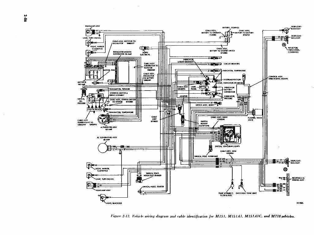

ELECTRICAL CIRCUIT NUMBERS FOR FIGURE 2-43
Circuit No. ! Description
40 68 75 76 77
77A 77B
90 91
41.5 460 461 490 500 501 502 368
Instrument lamp circuit Battery interconnecting cables Stoplight switch circuit Fuel pump circuit feed Fuel pump safety switch to fuel pump Circuit breaker to fuel pump safety switch Starter to fuel pump safety switch Trailer receptacle to ground Headlamp to ground Rectifier ventilator fan, loo-ampere alternator Turn signal light, right front Turn signal !ight, left front Clearance lamp blackout trailer feed Alternator to rectifier. loo-ampere alternator Alternator to rectifier, loo-ampere alternator Alternator to rectifier, loo-ampere alternator Ignition switch (via circuit 12) to 60.ampere alternator
Section VII. ENGINE DESCRIPTION AND MAINTENANCE (IN VEHICLE)
2-26. General
a. Description. The engine is four-cylinder, in- line, four-cycle, liquid-cooled, with overhead valves. Positive crankcase ventilation is provided through a closed system. All ignition system components are waterproof. Pressure lubrication, with a full-flow oil filter is provided by a gear-type oil pump. A built-in bypass in the top of the oil filter provides oil to the system in case the filter element becomes clogged.
b. Locational Terms. The fan end of the engine will be referred to as the “front”, and the flywheel end as the ‘%ear”. The terms left and right respectively, refer to the engine as viewed from the rear. The crankshaft rotates in a counterclockwise direction when viewed from the rear of the engine. Cylinders are numbered from the front.
c. Engine Data. Refer to table l-l for complete engine data.
2-27. Operations Performed with Engine in
Vehicle Operations authorized to organizational main- tenance personnel are to be performed with the engine installed in the vehicle. Refer to the maintenance allocation chart (app B) for the operations authorized to organizational main- tenance. Refer to the manual index to locate ap- propriate paragraphs on engine components or accessories.
2-28. Cylinder Compression Test
a. Start engine and run for a minimum of 1 / 2 hour at 1200 rpm. Turn ignition switch off.
NOTE Before making this test, valve stem to
rocker arm clearance must be adjusted to 0.015 inch.
b. Remove spark plugs. c. Pull the throttle control out to side open
position. Make sure the choke control is pushed in all the way against the instrument panel.
d. Insert compression gage (fig. 2-45) into the spark plug holes, beginning with No. 1 cylinder, and crank engine with the starter. Record the highest compression reading from each cylinder on DA Form 2404.
e. Repeat test on each cylinder, cranking the engine the same number of times for each cylinder as was required to obtain the highest reading on the No. 1 cylinder..
f. Compare the compression pressures of the cylinders. The indicated compression pressures are considered normal if the lowest reading cylinder is within 25 psig of the highest with a minimum allowable pressure of 85 psig. A low compression reading on two adjacent cylinders indicates the possibility of a leak from one cylinder to the other at the cylinder head gasket. The leakage may be caused by improperly tightened cylinder head bolts or a faulty cylinder head gasket. Tighten the cylinder head bolts to a torque of 60-65 lb-ft in the sequence shown in figure 2-46. Adjust valve to rocker arm clearance and check .cylinder com- pression again. If compression is still low on ad- jacent cylinders, there may be leakage because of a faulty cylinder head gasket. If leakage is present, install new cylinder head gasket.
g. If compression readings are uniformly low, the low compression may be due either to leakage at the valves or piston rings, or incorrect valve timing. Refer to support maintenance.
2-87

h. If compression pressures of cylinders vary more than 25 psig between the lowest or the highest, or are lower than 85 psig (after correc- tions indicated by the vacuum test have been made 1, notify support maintenance.
i. After completing compression test, adjust and install spark plugs.
i. Remove rocker arm cover. NOTE
After cylinder head bolts are tightened, valve stem to rocker arm clearance must be adjusted 0.015 inch.
2-29. Manifold Vacuum Test
a. Remove the pipe plug installed in the top rear of’ the intake manifold. Insert adapter on end of vacuum gage hose (fig. 2-471. Be sure all con-
nections are tight, as even a slight leak will result in a false reading.
b. Start engine and run at idling speed until minimum operating temperature (160° F.1 is reached. Check carburetor adjustments (para. 2-44 or 2-451.
c. With the engine idling at 600 rpm, vacuum gage should show a steady reading of from I7 to 2 1 inches of mercury. As a further check, open and close the throttle quickly. If the engine is in good condition, vacuum should drop to 2 inches at wide open throttle and quickly return to approximately 25 inches at closed throttle. If this action is not obtained, worn piston rings, improper intake valve seating, or an abnormal restriction in the car- buretor, air cleaner, or exhaust system is indicated.
2-88

HEADLAMP A5SY
LIGHT, COMPOSITE -
TURF& PARK 8 MARKER
@
460--(93460 ZO-CB zo-
491 -cf+491-
100 AMPERE ALTERNATOR
OPTION HORN. ELECTRICAL
ALTERNATOR 100 AMP
ITCH. ROTARY (IGNITION)
L CABLE ASSY. 11644836 461
IGNITION SYSTEM
TRANSMITTER PRESSURE
36
TO STARTER 1164487,-3
CABLE ASSY. POWER TO GROUND 10950992
4 AC GENERATING ASSY.
=? 60 AMP
I
LIGHT, COMPOSITE-TURN, / / r I- I
, I PARK .S MARKER
I I , ,
HEADLAMP ASS”
AT 39999 LIGHT. BLACKOUT
I.‘i,:L’ow :!- I C. 1 Ai& wiring diagram and identification for MlSlA2. 44825. and M718Al vehicles (1 of il.
2-90

BATTERY. STORAGE
CABLE ASSV.. BATTERY TO
GRbUNd-11644Bfi.2
CABLE ASSY. BATTERY TO
BATTERY 11644871.1
6
4 CABLE ASSY., BATTERY TO
STARTER SWITCH 11641871-4
INDICATOR. TEMPERATURE
MOTOR & BRACKET ASSY.. WINDSHIELD WIPER
CONTROL ASSY.. DIRECTIONAL
2, e 27J CIRCUIT BREAKERS
25 FLASHER 4 SOLlD STATE
LIGHT, COMPOSITE-TAIL.
STOP, TURN B MARKER
L CABLE ASSY., MAIN LIGH71NG 11660451
SWITCH. VEHICULAR LIGHTS
SWITCH. STOP, ELECTRO.MECHANICAL CABLE AS%., REAR 116.44896 LIGHT, COMPOSITE -TAIL.
STOP, TURN d. MARKER
‘2: x I I
:;:g I I
’ ’ 21.490 ! ! ?
--+_, i
GAS GAGE. TANK UNIT s ‘AT 39851
2-91

OR0 E5322
d. Incorrect valve timing is indicated by a steady reading of approximately 10 inches of mercury.
e. Weak valve springs are indicated by a rapid fluctuation of the gage hand when the engine is accelerated. If a valve sticks at times only, the vacuum drops 4 or 5 inches momentarily when the valve sticks. Fluctuation of the gage hand between 14 and 19 inches indicates that the valve guides are worn.
f. A slow movement of the gage hand between 12 and 16 inches indicates poor carburetion.
g. Leakage at the carburetor gasket is indicated by a low steady reading. Leakage of compression between the cylinders is indicated by the gage hand drifting regularly between 5 and 19 inches. Worn or poorly fitted piston rings or scored pistons and cylinder walls are indicated by the gage hand remaining lower than normal. at approximately I5 inches.
NOTE The above readings are for sea level operations. At higher elevations. the vacuum gage readings are lowered ap- proximately 1 inch of mercury for each 1000 feet increase in altitude.
h. After performing the manifold vacuum test, install the 1 / 4-inch pipe plug into the intake manifold. Tighten the plug.
2-30. Radiator Assembly
a. Removal. (1) Remove headlight connectors on all
models, and marker lig’ht connectors on Ml 5 1, M151A1, MlSlAlC, and M718 modeIs (fig. 2- 481.
(2) Remove six screw and lockwasher assemblies and six flat washers securing brush guard to fenders. Remove brush guard (fig. 2-491.
(3 1 Drain radiator coolant. (4) Loosen radiator hose clamp and pull
radiator inlet hose off engine outlet (fig. 2-501. (5) Loosen radiator hose clamp and puIl
radiator outlet hose off engine inlet (fig. 2-511.
b’i,uorr, 2- i.11. ll~~;trlli,d~ ;uzrl marker light connectors.
2-92

Figure, Z-51. Radiator inlet hose.
(6) Remove two lower mounting nuts, wash- ers and insulators (fig. 2-52).
(7) Loosen nut, lockwasher, and flat washer and slip radiator upper mount (rubber) from engine lifting eye bracket (fig. 2-53).
(8) Remove radiator. b. Installation.
(1) Refer to figure 2-48 through figure 2-53. l’he following attaching parts are to be torqued to the values shown: Radiator to support mounting nut (5 / 16-18) 5-8 lb-ft Radiator upper bracket to in- sulator (5 / 16-24 TM-81% lb-ft
(2 ) Replace radiator coolant.
2-31. Engine Mounting Cushions
a. Removal. f 1 I Remove front seats (para 2-198). (2) Remove transmission plate (para 2-199). (3) Remove two rear support mounting bolts
and washers (fig. 2-54).
Z-93’

:4; &i??oi;e :eff ;_.cY-: s’:;,>c--: -_. ^__ _ : _ _ i _ ._ -.- \, . ..__ __.._ _ I ., _
and washers (fig. 2-;i.S _ (5) Remove right front sugpor: .E?oiintii?g ‘3\?11
and washers (fig. Z-56). (6) Using suitable jack or hoist, raise engir_e
approximately one inch to gain clearar?ce _“:I-
removai of rubber cushions. (7 1 Remove mounting cushions.
b. Insialiation. Complete c!perations i 7 ! b2&.: i-2 (1) and refer to appropriate iiIustrn;ions 85 i2- dicated in a above.
2-32. Cylinder Head
a. Removizl.
(1) Drain cooling system. (2) Remove carburetor (para 2-44 ar,d Z-+.5.. (3) Remove intake manifoiG (para Z-~cii. (4) Remove exhaust manifold ‘dare Z-41. . . (.5) Remove thermostat (para 2-54;.
2-94

Fipurc Z-50. Remove connector and ventilation line.
I:igurr Z-60. Remove spark plugs.
h*igurc P-6 I. Back off adjusting screws.
2-95

I~‘i,cclrc~ Z-h.?. Kwker arm and shaft assembly removal.
/.‘i,<rtrc P-63. KWIOW had ,frorn block.
(6) Remove two rocker arm cvver nuts, washers and seals (fig. 2-57).
(7) Remove rocker arm cover and gasket. Remove gasket from cover and discard gasket.
(8) Remove two nuts. lockwashers and flat washers. Remove radiator top support rubber (fig. 2-58 ).
(9) Remove connector from water tem-
perature sending unit. Remove ventilation line from clip (fig. 2-59).
(10) Disconnect fitting securing spark plug cables to spark plugs. Remove spark plugs (fig. 2- 60).
(11) Loosen eight valve-adjusting screws one turn to reduce load on rocker arms (fig. 2-61).
( I2 1 Loosen two bolts securing the two rocker arm shaft center supports. Leave bolts in place (fig. 2-62).
(13 1 Remove nut, lockwasher and flat washer from rocker arm shaft front support stud (fig. 2- 62).
(14) Remove nut, lockwasher, oil inlet tube bracket and oil inlet tube from rocker arm shaft rear support (fig. 2-62 ).
( 15) Remove two bolts, two lockwashers, one flat washer and one oil outlet tube and bracket which were loosened in (12) above. Remove oil outlet tube from shaft assembly (fig. 2-63).
(16) Life rocker arm and shaft assembly from support studs (fig. 2-63).
(17) Remove eight valve push rods and four exhaust valve caps in sequence and mark for in- stallation in original position (fig. 2-64).
(18) Remove ten bolts and flat washers securing cylinder head to cylinder block. Remove head from block (fig. 2-65).
NOTE Do not pry between head and block. Damage to gasket surfaces will result.
b. Installation. To install the cylinder head reverse removal procedures and refer to figures 2- 65 back through figure 2-57.
NOTE Use new cylinder head gasket and new rocker arm cover gasket.
NOTE Engine does not have to be up to normal operating temperature before tightening cylinder head bolts. Apply sealer (MIL-S- 7916) (FSN 8030-543-4384) togasket and bolts before installing.
Tighten cylinder head bolts in three stages (fig. 2- 46) ; torque all bolts to 10 lb-ft ; torque all bolts to 45-55 lb-ft; torque all bolts to 60-65 lb-ft. Fill cooling system. Adjust valve clearance (para. 2-33). Torque rocker arm cover nuts to 3-4 lb-ft.
Z-33. Valve Tappet Adjusting Screw
a. General. The valve tappet adjusting screw has a self-locking interference-type thread. To remove the valve tappet adjusting screw, simply turn all the way out.
6. Adjustment. Minimum permissible adjusting screw torque is 5 ft-lb. (fig. 2-66).
(1) Operate engine for a minimum of 30
2-96

minutes at 1200 rpm to warm engine to normal operating temperature.
(2) Allow engine to idle and remove rocker arm cover.
(3) Insert feeler gage between valve stem and rocker arm pad and adjust to 0.015 inch.
(41 Examine rocker arm cover and gasket for damage; install new cover gasket if necessary. Torque nuts on rocker arm cover to 3-4 lb-ft.
Z-34. Oil Filter
a. General. The oil filter is a disposable type which is removed and discarded as an assembly when the oil filter is due for replacement. Replacement is accomplished without special tools, since it is designed for hand loosening and
tightening. The filter is full-flow type under full pump pressure and will show any leak immediately.
b. Replacement. (1) Place container under oil filter. Turn
counterclockwise to remove (fig. 2-67). (2) Install new filter by turning clockwise and
tighten securely. Operate engine and check for leaks.
NOTE Lubricate filter gasket prior to installation of new filter.
Z-85. Oil Filter Mounting Base on MlSI, M151A1, M718 and M151AlC
a. Removal. Refer to figure 2-68 and in- struction below to remove oil filter mounting base.
2-97

b’igure 2-67. Remove oil jilter and disconnect connector.
b’igurc ~-6% Kemovc fire1 pump sclfety switch
(M1.51. MlSlAl. MlSlAlC and M718).
I,‘iglrrr, Z-60. Kcmot’c scndinp unit and mocrntinp base.
\ I ) Remove oil filter (para. 2-34). (2 I Grasp electrical connector at fuel pump
safety switch (oil pressure safety switch) and pull, separating male and female connectors (fig. 2-67). -
2-98
(3 1 Loosen clamp screw and pull vent hose off fuel pump safety switch ( oil pressure safety switch) (fig. 2-68).
(4) Unscrew fuel pump safety switch (oil pressure safety switch) (fig. 2-68).
(5) Pull oil pressure sending unit electrical connector, separating male and female connectors.
(6) Unscrew oil pressure sending unit from oil filter mounting base (fig. 2-69).
(7) Remove two screw and lockwasher assemblies and flat washers (see fig. 2-69).
(8) Remove oil filter mounting base (fig. 2- 69). Remove and discard gasket. Clean mounting base thoroughly. Blow out all oil passages with compressed air.
b. Installation. Reverse removal procedures in a above.
NOTE Use new gasket when installing oil filter mounting base. Use care tightening oil pressure sending unit.
2-36. Oil Filter Mounting Base on M151A2, M825, and M718Al Vehicles
a. Removal.
NOTE Place container underneath filter to catch oil. (1) Unscrew and remove oil filter (para. 2-
34). (2) Disconnect oil pressure sending unit
connector., (3) Unscrew and remove oil pressure sending
unit from oil filter base (fig. 2-69). (4) Remove two screws, lockwashers and
flat washers securing base (fig. 2-69). Remove base and gasket. Discard gasket.
(5) Thoroughly clean mounting base making sure all oil passages are open by blowing out with compressed air.
b. InstaZlation. Reverse removal procedures in a above. Use a new gasket when installing oil filter
mounting base. CAUTION
Exercise care when tightening oil pressure sending unit during replacement.
2-37. Fuel Pump Safety Switch (Oil Pressure Safety Switch)
NOTE M151A2, M825, and M718Al vehicles have a mechanical fuel pump and no fuel pump safety switch.
a. Description. The fuel pump safety switch (oil pressure safety switch ; automatically stops the flow of fuel to the carburetor when the engine oil pressure falls below 3-l / 2 to 7-l / 2 psi. Thin action is accomplished by the switch cutting o& current to the electric fuel pump. To start the


(4) If no pressure is indicated, shut off engine and notify direct support maintenance. If pressure is indicated, replace safety switch.
2-38. Lines and Fittings
a. Inspection. Inspect all vacuum and fuel lines for leaks at fittings. Examine lines for cracks, bends, twists, or flattened areas.
b. Repair. Clean and dry all lines and fittings. Straighten slightly bent rigid lines. Remove broken or badly bent lines. Replace frayed, cracked or defective flexible lines.
2-39. Intake Manifold
a. Removal. Refer to fig. 2-71 through 2-74 for removing intake manifold.
(1) Remove air cleaner base and carburetor. (2) Unscrew vent line fitting from intake
manifold (see fig. 2-71). (3) Disconnect all vent lines from crankcase
ventilation metering valve and fitting (see fig. 2- i2).
(2) Unscrew crankcase ventilating valve and fitting from intake manifold.
(5) Remove two bellcrank screws and lock- washer assemblies securing accelerator bellcrank bracket to intake manifold. Remove bellcrank (see fig. 2-13).
(6) Open tabs on dual tab washer and remove two screws and tab washer securing intake manifold to cylinder head.
(7) Remove six screws and four lockwashers. securing intake manifold to cylinder head. Remove intake manifold and discard the two gaskets (see fig. 2-14).
b. Installation.Refer to figs. 2-74 to fig. 2-71 and reverse removal instructions to install intake manifold.
NOTE Always use new gaskets at installation.
The following torque values apply for installation: Four 1 I/ inch long mounting screws 23-28 lb-ft Two 1 l/z inch long mounting screws lo-12 lb-ft After installation, apply a small amount of oil at the carburetor and intake manifold flanges while engine is running. to determine if a leak is present at the intake manifold gasket. If oil is drawn in. the manifold is leaking.
i.‘igurc Y-71. Unscrew cent fine fitting from intake manifold
I.‘i,gytrc> P-7~. IXsconncct wnt lines from zalce and fitting.
2-100

I.Ygurp Z-74. Remove intake manifold.
2-40. Exhaust Manifold a. Removal.
(1) Remove intake manifold (para 2-39). (2) Remove two brass nuts securing inlet pipe
to exhaust manifold (fig. 2-75). (3) Remove bolt and lockwasher securing
exhaust manifold flange to block (fig. 2-75). (4) Open locking tabs on four mounting bolts
and remove bolts and two clamps (fig. 2-75). (5) List off exhaust manifold and discard inlet
pipe gasket (see fig. 2-76). NOTE
No gasket is used between the cylinder head and the exhaust manifold. Coat port areas with sealant (FSN 8030-252-3391) prior t0 installation.
b. Installation. Perform operations (5) back through (I) and refer to figs. 2-76 and 2-75 for instructions to install exhaust manifold.
NOTE Always use a new exhaust pipe gasket when installing exhaust manifold.
For installation, secure mounting bolts to a torque 12-16 lb-ft. Install intake manifold (para 2-39):
2-41. Clutch Linkage Adjustment
a. General.Clutch pedal free travel of 1 M to 1 l/2 inches must be maintained. Free travel is the distance between the clutch pedal released position and the point when the clutch starts to disengage. If free travel .is not maintained, slippage occurs between the clutch facings and causes the facings to become worn.
b. Adjustment. ( 1) Remove clutch return spring located on left
side of engine (fig. 2-77). (2 1 Slip rod out of clutch release equalizer
shaft lever and rotate the rod until the pedal free travel is obtained (fig. 2-77).
(3) Depress clutch pedal and check for pedal free travel of iI/ inches to 1 I/ inches (fig. 2-78).
I:igurr Z-75. Remmw bolts from exhaust manifold.

-
I~‘it.wrc P-78. Clutch pedal free travel.
Section VI I I.
i-42. Description and Data
a. GeneraLThe units comprising the fuel and air intake system include the carburetor, air cleaner, fuel pump, fuel filter, fuel tank, connecting fuel lines, and electric wiring for the fuel pump. Figure 2-79 is a view of the fuel and vent lines. Figure 2-80 is a schematic of the accelerator pedal, throttle, and choke control.
b. Carburetor. The carburetor is a side draft, single barrel type, mounted on the intake manifold on the left side of the engine as viewed from the driver’s seat. Vehicles may come equi,pped with either a Holley or Zenith carburetor. The car- buretor is mechanically controlled by the ac- celerator pedal, hand throttle and manual choke. For deepwater fording purposes, the Holley carburetor is extremely vented to the air cleaner. The Zenith carburetor is internally vented.
NOTE M151A2, M825, and M718AI vehicles have a mechanical fuel pump requiring no electrical wiring.
c. Air Cleaner. All Ml5 1 series vehicles are equipped with an oil bath type air cleaner that is mounted on brackets attached to left front fender panel inside the engine compartment. A flexible air hose connects the air cleaner unit to the carburetor. The carburetor float chamber is vented to the air cleaner (only on vehicles equipped with Holly carburetor). The M151, M151A1, M151AIC, and M718 vehicles have a fuel pump safety switch (oil pressure safety switch) which is also vented to the air cleaner unit. The air intake cap can be replaced by an air intake pipe extension for deep-watei fording purposes.
d. Fuel PLmp and Filter. (1) On the Ml51, Ml5lAI, M151AlC and
M718 the fuel pump and filter assembly is lbcated
2-102
FUEL SYSTEM
inside the fuel tank as a single unit, and is ac- cessible from the top of the tank. The fuel pump is a 24-volt, electrically operated, plunger type. The pump contains a hollow steel plunger in a brass cylinder. Valves are attached to the lower end of the plunger and the cylinder. The valves operate in the same manner as a common lift pump. The plunger has no seal, but is freely fitted in the cylinder. The fuel itself provides a seal between the piston and the cylinder. This principle permits the pump to maintain a pressure of approximately 4 psi. The solenoid causes the plunger to compress the pumping spring. The spring design governs the pump static pressure. All fuel entering the pump passes through the filter element in which the pump is completely enclosed. The electrical connection is waterproof. The fuel pump is controlled by a double-&row safety switch, the mechanical linkage being actuated by oil pressure from the‘engine main oil gallery. One contact of the switch forms a series connection between the fuel pump and the starter switch. The other contact forms a series connection between the ignition switch and the fuel pump. When the starter switch is depressed, the first circuit is closed, and the fuel pump operates. Pump operation continues after releasing the starter switch since the safety switch opens the first circuit and closes the second circuit when the engine oil pressure reaches 2% to 51/2 psi. All parts of the electrical circuit are tamperproqf and hermetically sealed in helium atmosphere. The pump is radio- interference suppressed: The filter element is replaceable, self-contained, and of a cylindrical type. It is made from helically wound ribbons of phenolic-resin-impregnated cellulose. Any im- purities in the fuel are deposited on the entrance edges of the ribbons where they can be easiiy cleaned off without damage to the filter element.


CHOKE CONTROL t
THROTTLE CO
2-104

I+‘i,gurr 2-81. Fuel and vent lines on M151AZ. M825. and M718Al vehicles.
I,‘igccw 242. &with carburetor installed on M15IA2. M825. and M i’I8A I vehicles.
(1) The fuel line on MlSI, MISlAl, MlSlAlC, and MT18 consists of formed metal tubing from the fuel pump to the engine com- partment. a coupling, and a flexible hose to the carburetor.
(2) The fuel line on MlSIA2, M825 and M718Al consists of formed metal tubing leading from the fuel tank to the mechanical fuel pump mounted to right side of engine block. ,From .ibe
fuel pump, the line goes to the carburetor. From the carburetor, a vapor return line goes to the fuel tank.
g. Data. Refer to table l-l for tabulated data.
Z-43. Air Cleaner
a. Servicing Air Cleaner.
(1) Loosen clamp and remove air cleaner cover (fig. 2-83 or 2-84).
NOTE Do not remove clamp from cover. (2) Lift out air cleaner element (fig. 2-851.
NOTE When removing cover be careful of rubber gasket; if loose apply adhesive to cover and install rubber gasket. Use adhesive (MIL- C-50921 (FSN 8040-221-3811).
(3) Lift out oil cup (fig. 2-861. Discard used oil. Clean oil cup, air cleaner element, and air cleaner body, using dry-cleaning solvent or miner spirits paint thinner.
(41 Place oil cup in body and fill to level mark with fresh engine oil (fig. 2-87). Refer to LO 9- 2320-218-121. Install air cleaner element and secure air cleaner cover.
b. Removal. (2) Loosen clamp screw and clamp at air
intake hose. Remove hose from air cleaner (fig. 2- 88).
(2) Loosen clamp on carburetor float chamber vent hose, (Halley Carburetor only). Pull hose from tube (fig. 2-891.
2-105

I+‘igurca 2-84. Remove air cleaner cover (Zenith).
I* igctw 245. Kcmow air cleaner element.

/~‘i,~O,? L’-‘l/j. l~~‘1~1OU’ air c~li’itrlf~r /lldlC~~/.
(3) Unscrew fuel tank vent hose fitting. Loosen clamp on fuel pump safety switch (oil pressure safety switch) vent hose. Pull hose from tee (fig. 2- 89).
NOTE Instruction in (3) above apply only to earlier M 15 1 series models. M I5 IA2 models do not have fuel pump safety switches. (4) Remove four screws, washer assemblies
and nuts securing air cleaner to brackets and remove air cleaner (fig. Z-90).
c. Installation. Perform removal operations (4) back through (l), and refer to figures 2-90 back through 2-88.
2-44. HoIIey Carburetor
a. Adjustments ( 1) General. Adjustment of the carburetor ,is
accomplished by means of the idle mixture ad- justing screw (fig. 2-91) and the idle speed ad. justing screw. Make all carburetor adjustments with engine running at normal operating tem- peratures.
(2) Idle mixture. Carefully turn the idle mixture adjusting screw in until it just touches the needle seat or the engine begins to lag; then turn OUT until the engine operates smoothly (ap- proximately one full turn).
(3) Idle speed.The idle speed adjusting screw on the throttle lever (fig. 2-9 I) should be set to idle the engine speed at 550-600 rpm.
b. Removal. (1) Disconnect ventilation tube fittings.
Expand clamp on float chamber ventilation hose. Pull hose from fitting. Loosen intake air hose clamp. Pull hose from carburetor (fig. 2-92).
(2) Disconnect fuel return hose at carburetor Ifi1 1.5JA2. MH2.5. and MY18Al only) (fig. 2-82).
(3) Disconnect flexible fuel supply line at carburetor (M1.51. MlSlAl, Ml5lAlC ’ and M’il8 only) (fig. 2-93).
(4 1 Loosen clamp and disconnect fuel inlet host from in-line fuel filter. Disconnect in-line fuel filter at carburetor (M151A2. M825 and M’il8Al only) (fig. 2-82).
(5 1 Loosen two screws retaining choke control cable and housing and pull cable assembly through clamp (fig. 2-94).
(6) Disconnect throttle linkage at throttle valve arm ball joint socket (fig. 2-95).
(‘i) Remove retracting spring. Remove two carburetor mounting nuts, lockwashers and flat washers. Remove accelerator retracting spring bracket (fig. 2-96).
(8) Move carburetor and gasket away from intake manifold. Discard gasket (fig. 2-124).
c. Installation. (1) Clean carburetor gasket surfaces on
carburetor and intake manifold before installing gasket and carburetor.
(2) Clean hose connections before installing hoses.
(3) Perform removal operations (8) back through (1) to install carburetor.
NOTE Use a new gasket when installing car- buretor (4) Bring engine up to normal operating
temperature. (5 ) Adjust carburetor.
2-45. Zenith Carburetor
a. Adjustments. Adjustment of the Zenith carburetor is accomplished by the same means as that of the Holley carburetor, in relationship to the idle mixture adjusting screw and the idle speed adjusting screw (fig. 2-91).
b. Removal of Zenith Carburetor. The Zenith carburetor can be removed by using the same procedure as given in operations (1) through (8) paragraph 2-44 for removal of Holley carburetor, except for deletion of float chamber vent hose.
c. Installation of Zenith ‘Carburetor. Install the Zenith carburetor (fig. 2-82 or 2-98) using the same procedure as given for the Holley carburetor (para 2-44).
NOTE Torque-tighten attaching screws 65-85 lb-in.
2-107

2-108

I, ICI,, ,’ L’- I I)_‘. I~V~JJ~WP ifrwl~~r;~lr~r pdi~i.
d. Idle Mixture and Speed. After the engine temperature stabilizes (15-20 min.) adjust the idle adjusting needle for smooth engine speed or highest intake manifold vacuum. Readjust the throttle stop screw for 500 rpm idle speed, and recheck the idle adjusting needle setting. If the engine speed in-
creases. readjust the stop screw to obtain 500 rpm.
2-109

2-46. Accelerator Pedal
a. Removal. (1) Remove accelerator pedal return spring
and trunnion retaining clip (fig. 2-99). (21 Remove accelerator road to pedal clip (fig.
2-100). (3 1 Loosen throttle stop screw and remove stop
from throttle cable. Disconnect throttle cable swivel from accelerator pedal (fig. 2-101).
(41 Remove two screws and lockwashers from accelerator pedal bracket. Remove accelerator pedal (fig. 2-102).
b. Installation. Install accelerator pedal by reversing removal operations (4) back through (1). Refer to figures 2-102 back through 2-99.
c. Adjustment. Adjust threaded trunnion on accelerator pedal rod (fig. 2-99) to obtain wide open throttle at carburetor with I/! inch clearance under accelerator pedal pad. Obtain the adjustment as follows: With the accelerator or rod discon- nected at the bellcrank, pull hand throttle out until accelerator pedal rests on floorboard. Block car- buretor to full open position. Adjust threaded link to a slip fit in bellcrank. Turn link approximately one full turn to the right, and reassemble.
2-47. Choke Control Cable Assembly
a. Removal. (11 Loosen clamp screw to loosen air intake
hose clamp. Pull hose away from carburetor (fig. 2- 1031.
(2) Loosen choke control housing clamp screw. Loosen cable stop screw. Pull control cable and housing assembly from stop and clamp (fig. 2-941.
(31 Remove nut and lockwasher behind in- strument panel from choke control cable and housing assembly (fig. 2-1041.
(41 Remove cable and housing assembly through firewall grommet and through firewall. If necessary, remove retainer securing grommet to firewall (see fig. 2-105).
h. Installation. Install choke control cable assembly by reversing removal operations (4) back through (11. Refer to figures 2-105 back through 2- 103.
NOTE Before completing operation (21 perform adjustments c(3) and ~(4) below.
c. Adjustment. Refer to figures 2-l 03 and 2-105 and proceed as follows:
(1 I Remove air cleaner hose at carburetor to view the choke control plate when making ad- justment.
(2) Loosen screw at the choke control cable stop at carburetor.
(31 Set choke control knob 1 / 16 inch out from instrument panel.
(41 Adjust choke control cable so the choke
control plate in the carburetor is in fully open position.
2-110

(5) Secure cable and install air cleaner hose,
Z-48. Throttle Control Assembly
a. Removal. (11 Loosen setscrew on stop and remove
throttle control cable from swivel (fig. 2-106). (2) Remove nut and lockwasher behind in-
strument panel and remove throttle control assembly through instrument panel (fig. 2.134).
b. Installation. Install throttle control assembly by removal operations. Refer to figures 2-107 and 2-107.
NOTE Before completing the installation operations be sure that accelerator ad- justment is made and adjustments c (3) and c (4) below are performed.
c. Adjustment. Refer to figures 2-106 and 2- 107 and proceed as follows:
(1) Loosen setscrew at cable stop. (2 1 Set hand throttle control knob 1 / 16 inch
out from dash panel. (3) Adjust throttle control cable so throttle
control plate at carburetc * is in fully closed position. (4) Tighten setscrew.
2-49. Fuel Pump (In Tank, Electrical, M151, MlSlAl, MlSlAlC and M718) or Fuel Tank Cover (MlSlA2, M825 and M718Al)
a. Removal. WARNING
Drain sufficient fuel from tank before removing fuel pump or fuel tank cover to prevent overflow. During removal operation, do not allow sparks or open flame near fuel tank.
CAUTION Disconnect battery ground cable. (1) Remove seats. (2) Disconnect electrical connectors from fuel
pump (Ml51, MISlAl, MlSlAlC, and M718) and sending unit (fig. 2-108). Disconnect fuel and vent tubes. Remove ten screws and lock- washers securing fuel pump (Ml51, MlSlAl, MlSlAlC, and M718) or fuel tank cover (MlSlA2, M825, and M718Al) to fuel tank.
(3) Lift fuel pump or fuel tank cover out of Itank. Removal and discard gasket (fig. 2.109).
b. Installation. Clean gasket surfaces on fuel pump (Ml51, MlSlAl, MlSlAlC, and M718) or fuel tank cover (MlSlA2, M825, and M718A1), and fuel tank before installing pump or cover and gasket.Install pump or cover by reversing removal operations (3 1 back to ( 1). Refer to figures 2-109 and 2-108.
c Testing Fuel Pump Pressure. i 1). Disconnect tube at carburetor. (21 Using a pressure gage, hold tapered
adapter to fuel tube. (3 1 Start engine. Engine should normally
operate due to sufficient fuel in carburetor. If engine does not start, continue operating starter until maximum reading on pressure gage is ob- tained. Correct pressure is from 4.9 to 5.4 psi. If pressure is incorrect, replace fuel pump,
(4) Recheck pressure and connect fuel tube.
2-50. Fuel Pump (M141A2, M825 and M718Al Vehicles)
a. Removal. (1) Loosen clamp and disconnect fuel inlet
hose at mechanical fuel pump (fig. 2-110). (2) Disconnect vent and fuel supply lines at
fuel pump (fig. 2-1111. (3) Remove two screws and lockwashers
securing fuel pump to engine block. Remove pump and gasket. Discard gasket.
b. Installation. Clean surfaces for pump gasket before installing fuel pump. Use new gasket and install pump by reversing procedures in a above.
c Testing Fuel Pump Pressure. (1) Disconnect fuel line at filter (fig. 2-82). (2 1 Use pressure gage. Hold tapered adapter to
fuel line tube. (3 ). Start engine. Engine should operate due to
normal amount of fuel in carburetor. If engine does not start, continue cranking engine until a correct reading of from 5 to 6 psi is obtained. If pressure is incorrect, replace the pump assembly.
(4) Recheck pressure and connect fuel line to filter.
2-51. Filter Element and Pump Motor (M151, MlSlAl, MlSlAlC and M718)
a. Removal. NOTE
During the disassembly operation, parts that are to be reused should be handled carefully to prevent damage. (1) Remove fuel pump from gas tank (para. 2-
49). (2) Remove three screw and lockwasher
assemblies securing filter retaining plate to un- derside of pump (fig. 2-112).
(3) Remove two filter gaskets, filter element, upper gasket spacer ring, and spring washer (fig.. 2- 113).
(4‘) Cut pump motor lead wire under the top cover plate (fig. 2-113).
2-111

I*‘i,~ttrc 2-IOh. Kctntmr throul~ contrttl cable from swivel. . .
I:i,cttrc* P-l 00. Ketnovcptnp and gasket
iM151. MlSlAl. MlSlAlC. and M718).
2-112

(51 Remove compression nut, top jam nut, and lockwasher securing pump motor to mounting plate (fig. Z-1131.
(61 Remove lower jam nut from pump motor (fig. 2-l 13).
(71 Remove flared nut and fuel line tube from the fuel fitting in the top cover plate. (fig. 2-113)
(8) Remove electrical terminal nut using special wrench provided with Kit (57033091.
Remove terminal and lead wire from the terminal housing (fig. 2-113).
(91 Remove rubber grommet from pump motor mounting plate (fig. 2-113).
b. Installation. NOTE
Use new parts supplied in fuel pump kit
(57033091 ( 1) Install the fuel line tube and flared nut to
the fuel fitting in the top cover plate. Tighten the
nut (fig. 2-1131. (2) Thread lower jam nut to the pump motor
to a dimension of approximately 5 / 32 of an inch measured from the bottom of the nut to the top of the shoulder on the cover boss (fig. 2-1131.
(31 Hold top cover plate upside down. Place compression nut, sleeve, top jam nut, and lock- washer on the fuel line tube (fig. 2-l 13)
(4) Insert pump motor lead wire and cover boss through mounting plate. Check the ‘i.635- 7.575 inch dimension from bottom of top cover plate to the bottom of pump motor. Adjust lower jam nut, if necessary, to conform to this dimension. Tighten the upper jam and compression nut (fig. 2-
1131. (51 Insert rubber grommet over pump motor
lead wire and press into position in mounting plate
(fig. 2-l 13 1. (6) Assemble in their proper order, to the
terminal housing. the insulating washer, steel washer, pump motor lead wire, terminal shell, shell cup. and terminal nut. Tighten terminal nut using special wrench provided with Kit (5703309) (fig. 2-l 131.
CAUTION Care should be taken during this operation to insure that the terminal shell is seated
against terminal housing to allow the in- sulating washer to isolate the terminal. otherwise an electrical short will result.
2-113

\ 1 \ -- r- Ll I
I I ITi I
I I trcL --
I I
I
MOUNTING
PLATE
I SPRING WASHER ,
I
I I I
--- --
--
-_--
-_-
---
I LOCKWASHER HOUSING
COMPRESSION NUT
\
I I FUEL LINE
/
TUBE
FLARED NUT
PUMP MOTOR
UPPER FILTER
FILTER ELEMENT
RUBBER GROMMET
iOP COVER
PLATE
STEEL WASHER
1 LbwER FILTER
I GASKET
PUMP MOTOR
INSULATING
WASHER
SECTION A-A w
AT 39832:
2-114

i (7 1 Make the necessary connections and check thd flared nut and compression nut for leaks while pumping fluid. If leakage exists. tighten nuts further. If leakage still exists, pump assembly cannot be used.
I8 1 Assert] ble in their proper order, the spring washer, spacer ring, upper filter gasket, filter element, lower filter gasket. filter retaining plate, and three screw and lockwasher assemblies (fig. 2- 112 and 2-113).
(9) Install fuel pump in ‘gas tank (para 2-491.
262. Replacing Fuel Filters on MlSlA2, M825 and M718Al Vehicles
a. Removal (In-Line Fuel Filter). (11 Remove hose clamp at fuel inlet hose. See
figure 2-82 and remove hose from filter. (2) Unscrew filter from carburetor and remove
(fig. 2-82 1. b. Installation (In-Line Fuel Filter). Install new
fuel filter in reverse of above procedure.
c. Removal (In-Tank Fuel Filter). (11 Remove fuel tank cover (para 2-49). (2) Remove and discard fuel filter from end of
fuel supply tube (fig. 2-114). .d. Installation (In-rank Fuel Filter). Install new
fuel filter in reverse of above procedure.
2-53. Fuel Tank
a. Removal. (1) Disconnect battery ground cable (fig. 2-
182). (2) Remove driver’s seat (para 2-198).
NOTE Place a suitable container directly under fuel tank drain plug.
(3) Drain tank by removing plug (fig. 2-115). WARNING
Do not allow any sparks or open flame near fuel tank. (4) Disconnect electrical connectors at fuel
level sending unit and fuel pump on M 15 1, M152A1, M151AlC and M718 (fig. 2-108). Dis- connect fuel lines and vent line at tank connecting points.
(5) Remove four fuel tank mounting screws and lockwashers (fig. 2-l 16).
(6) Carefully lift tank away from vehicle (fig. 2-l 17).
NOTE Use care not to damage or distort attach’ing fuel and vent lines during removal
procedures.
h. Installation. I1 ) Position fuel tank in vehicle and secure
with four screws and lockwashers (figs. 2-l 16 and 2-1 1 TI.
(2) Connect fuel line and vent line. Connect electrical connector at fuel level sending unit and fuel pump on M 15 1, M151A1, M151AlC and My18 (fig. 2-108).
(3) Replace driver’s seat. (4) Replace drain plug. (5) Connect battery ground cable (fig. Z-182).
2-54. Fuel and Fuel Ventilation Tubes, Hoses and Connectors
a. General.Figrrre 2-108, 2-l 18, and 2-l 19 show the fuel and fuel ventilation tubes, hoses, and connections in the engine and passenger com- partments.
NOTE
Figure 2-119 shows fuel vent line on M151A2, M825, and M718AI vehicles.
b. Removal. All fuel and fuel ventilation tube connections are made with flared end male-and- female-type fittings. To remove a tube, hose or fittini. used suitable tools and disconnect and remove.
c. Installation. When installing fuel and fuel ventilation tubes, start all threads by hand, being careful not to cross thread the connection. Tighten all connections securely, but do not overtighten. Inspect for leads. Make certain that electrical
.connectors are completely engaged.
FUEL TANK COVER
IN-TANK FUEL FILTER
b-%_
FUEL SUPPLY TUBE
AT 39785
I*‘i,grrrcs 3-114. In-Tank /cwl/iltcrorr M151A2.
M8.25 and M718Al vehicles.
2-l 15

;._
2-116

Section IX. EXHAUST SYSTEM
2-SS. Description
The exhaust system consists of a muffler inlet pipe, muffler, front outlet pipe, rear outlet pipe and a
tailpipe extension, together with necessary clamps, gaskets, bolts, nuts and lockwashers. Figure 2-120 shows the exhaust system.
2-S6. Muffler Inlet Pipe
a. Removal. (2) Remove two brass nuts and lockwashers
securing muffler inlet pipe to exhaust manifold and discard gasket (fig. 2-1211.
(21 Raise vehicle and remove four bolts from rear universal joint of front propeller shaft (fig. 2- 1221.
(3) Remove two bolts, washers, and locknuts from clamp securing muffler inlet pipe to muffler inlet. Remove clamp and discard gasket (fig. 2- 1231.
b. Installation. Install muffler inlet pipe by reversing removal operations. Refer to figures 2-
J 23 back to 2-121. Torque the following parts to
the values shown:
Muffler inlet pipe to exhaust 1
manifold nuts (sh-241 Muffler inlet pipe clamp locknut
(5 / 16981 Universal joint bolt (5 / 16-241
NOTE
1 S-20 lb-ft
8-l 2 lb-ft 1 S-20 lb-ft
Use new gaskets for installation.
2-57. Muffler
a. Removal. (1) Lift vehicle and remove four bolts from
front end of rear propeller shaft (fig. 2-1241. (2) Remove locknuts, washers and bolts from
clamp securing muffler inlet pipe to muffler. Remove clamp and discard gasket (fig. 2-1251.
(3) Remove locknuts, washers and bolts from clamp securing front outlet pipe to muffler.
Remove clamp and discard gasket (fig. 2-1261. (4) Remove locknut and bolt from muffler
retainer clamp and remove muffler (fig. 2-127).
2-117

2-118
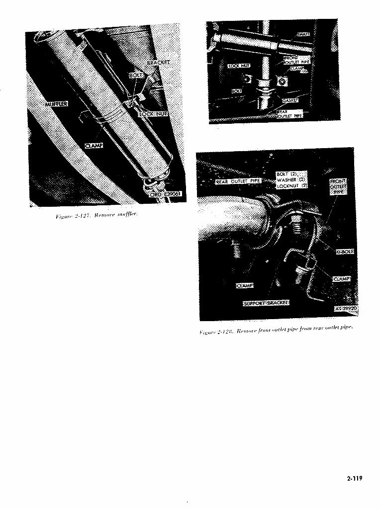
2-119

b. installation. Install muffler by reversing removal operations. Refer to figures 2-127 back to 2-124. Torque the following parts to the values shown :
Muffler. retainer clamp locknut (5 / 16-181 8-12 lb-ft Muffler inlet pipe clamp locknut (5 ,’ 16-181 8-l 2 lb-ft Muffler front outlet pipe clamp locknut (5 / 16-18) 8-12 lb-ft Universal joint bolt (5 / 16-24) 15-20 lb-ft
NOTE Use new gaskets at installation.
2-S8. Front Outlet Pipe
a. Removal. (1) Loosen muffler retaining bracket nut and
bolt. Loosen bracket (fig. 2-127). (2) Remove locknuts, washers and bolts from
clamp securing front outlet pipe to rear of muffler. Remove clamp and discard gasket (fig. 2-1261.
(3) Remove Us bolt and clamp securing front outlet pipe to support bracket (M 151A2, M825 and M718Al only1 (fig. 2-1281.
(41 Remove two locknuts, washers and bolts from clamp securing front outlet pipe to rear outlet pipe (fig. 2-1281. Remove clamp and discard gasket. Work pipe down and out, rotating as necessary to clear drive shaft.
b. Installation. Install front outlet pipe by reversing removal operations. Refer to figures 2- 128 back through 2-126. Torque the following parts to the values shown: Muffler front outlet pipe clamp locknut (5 / 16-181 8-12 lb-ft Muffler rear outlet pipe clamp locknut (5 / 16-181 8-l 2 lb-ft
NOTE Use new gaskets at installation.
2-59. Rear Outlet Pipe
a. Removal. (1) Remove two locknuts, washers, and bolts
from clamp securing rear outlet pipe to front outlet pipe. Separate clamp and remove it from pipe (fig. 2-1281.
(2) Loosen two locknuts from bolts securing clamps to rear outlet pipe and support bracket ~M151,M151Al,Ml51AlCandM718only) (fig. 2-129).
(31 Remove two locknuts, washers, and bolts from clamp retaining rear outlet pipe to frame.
Remove rear outlet pipe and tailpipe extension from vehicle. Discard front outlet pipe to rear outlet pipe gasket (M151, Mi52A1, Ml5lAlC and M718 only (fig. 2-1301.
(41 Remove U -bolt and clamp retaining rear outlet pipe to frame. Remove rear outlet pipe and tailpipe extension from vehicles. Discard front outlet pipe to rear outlet pipe gasket (MI51A2. M825 and M718Al only) (fig. 2-130).
(5) Remove tailpipe extension from rear outlet pipe (para 2-601.
b. Installation. Install rear outlet pipe .by reversing removal operations. Refer to figures 2- 130 back through 2-128. Torque the following parts to the values shown: Muffler front and rear outlet pipe clamp locknut 5 / 16-181 8-12 lb-ft Rear outlet pipe support bracket locknut (5 / 16-181 8-I 2 lb-ft
NOTE Use new gaskets for installation.
2-60. Tailpipe Extension
a. Removal. (1) Remove two bolts and locknuts securing
tailpipe extension to rear outlet pipe (fig. 2-13 1). (2) Remove tailpipe extension and gasket.
Discard gasket. b. Installation. Install tailpipe extension by
reversing removal operations. Refer to figure 2- 13 1. Torque value for nuts is 12-15 lb-ft.
NOTE Use new gasket at installation.
I*‘igtrrca 2-129. Disconnccl rear outlei pipe and bracket
(M151. M151Al. MlSlAlCand M718).
2-120

Section X. COOL
a. Description.
i J 1 Coo!ing system. The cooling system is a forced circulation. pressurized type and consists of the water pump. fan. shroud. drive belts. ther- mostat. hoses. radiator. and a pressurizing radiator filler cap. The coolant is drawn from the lower tank of the radiator by the water pump and is circulated through the cylinder block and cylinder head. After circulating throughout the cylinder block and cylinder head. the coolant is forced through an outlet connection past the thermostat. if it is open. into the upper tank of the radiator. As the coolant
.ING SYSTEM
drops to the lower tank of the radiator, it is cooled by air drawn through the radiator by the fan and the motion of the vehicle. When, because of in- sufficient operating temperature, the thermostat is closed. constant circulation of the coolant is provided by a drilled passage connecting the cylinder head with the intake side of the pump.
(21 Water pump. The water pump is a cen- trifugal-type unit mounted on the front of the cylinder block. and driven by two or three V -belts depending on the generator used. The pump shaft and double row ball bearing are integral. The bearing is packed with special high-melting point
2-121

grease at the time of manufacture and requires no further lubrication. The shaft and bearing unit assembly is retained in the housing by a snapring. The seal assembly is pressed into the pump housing. On side of the thrust washer of the seal assembly bears against the machined surface of the impeller and the other side is cemented to a rubber bellows which is in turn cemented to the seal retainer. A coil spring, an integral part of the seal, maintains a constant pressure against the thrust washer and the machined surface of the impeller, assuring a positive seal. A drain hole is provided in the bottom of the housing to prevent water seepage past the seal from entering the ball bearing. The pump pulley hub is pressed on the pump shaft.
(3) Fan. The fan is a four-blade type with blades spaced irregularly to dampen noise. The fan is bolted to the water pump hub which is pressed on the pump shaft. The bolts used to fasten the fan blades also retain the water pump fan pulley, which is driven from the crankshaft pulley by V -belts.
(4) Radiator.The radiator is of vertical tube- and-plate fin construction, utilizing a pressure filler cap which maintains a pressure of approximately seven pounds per square inch. By operating under this pressure. the boiling point of the coolant is raised approximately 19 degrees. An overflow tube is provided on the radiator to allow the escape of coolant and / or pressure when the pressure rises above the limit of the pressure cap. The radiator cap assembly also contains a vacuum relief valve which allows air into the radiator if a vacuum is created. Drain cocks are located at the left rear side of the cylinder block and at the bottom center of the radiator to provide for complete drainage of the coolant. The radiator is mounted to support brackets using rubber insulators. The brackets are bolted to both sides of the engine block. A rubber insulator support is provided at the center of the top of the radiator to control fore and aft motion of the radiator.
(51 Radiator shroud. The radiator shroud is attached to the radiator and is designed to prevent recirculation of the air.
(6) Thermostat. The thermostat is a, spring and cartridge-type. located in the cylinder head and retained by the water outlet connection. The thermostat restricts the flow of coolant to the radiator until a predetermined temperature is reached. thus maintaining an efficient operating tern perature.
b. Data. Refer to table l-1 for tabulated data.
Z-62. Radiator Hoses
a. Removal. (1) Open drain cock and drain radiator (fig. 2-
134). Loosen clamps and pull hose from inlet of radiator and from outlet of cylinder head (fig. 2- 132).
(2) Loosen clamps and pull hose from water pump inlet and from radiator outlet (fig. 2-133).
b. Installation. Clean hose connections before installing hoses. Install hoses by reversing removal operations. Refer to figure 2-133 and 2-132.
I~i,<i’t/,~,~ L’-/.7d. /~vr~fow /ofwr rarliiilor. Iff~r.
Torque clamps to 18-22 lb-in. Fill cooling system as specified in LO 9-2320-218-12.
NOTE Check for coolant leaks
2-(,S. Radiator
a. Removal. (I ) Open drain cock and drain radiator (fig. 2-
134). (2) Loosen screw in radiator hose clamp and
pu11 inlet hose from radiator (fig. Z-132). (3 1 Loosen nuts and remove radiator insulator
assembly from radiator support and engine lifting eye (fig. 2-1351.
(4) Loosen radiator hose clamp and pull outlet hose from radiator (fig. 2-133 1.
2-122

t 5 I Remove two lower mounting locknuts. flat washers. and insulators (fig. 2-1341.
(01 Remove six screw and lockwasher assemblies from fan shroud and remove radiator (fig. 2-136).
b. Installation. Install radiator by reversing removal operations. Refer to figures 2-136 back to 2-132. Torque the following attaching parts to the values shown :
Radiator to support mounting nut (5 ,’ lfL18) 5-8 lb-ft. Radiator upper bracket to insulator and insulator to engine lifting eye ‘i.5-8.5 lb-ft. Radiator upper insulator bracket to head bolt (5 / 16-18) T-l 1 lb-ft. Fill cooling system as specified in TM 9-2320-218- 10.
2-64. Thermostat
a. Removal. ( 1) Open drain cock and drain radiator (fig. 2-
134). (2) Remove radiator upper hose ,(fig. 2-1321. (3) Remove two screws and lockwashers
retaining coolant outlet to cylinder head (fig. Z- 137).
(4) Remove coolant outlet and gasket. Discard pasket (fig. 2-138).
2-123
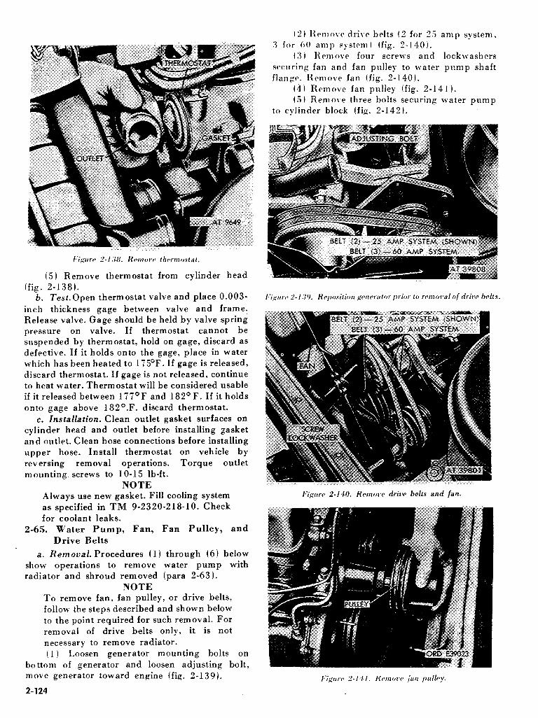
/:igrrrr 2-ll:;Il. KWIOW lh/*rrtloslal.
(5) Remove thermostat from cylinder head (fig. 2-J 38).
b. Test.Open thermostat valve and place 0.003- inch thickness gage between valve and frame. Release valve. Gage should be held by valve spring pressure on valve. If thermostat cannot be suspended by thermostat, hold on gage, discard as defective. If it holds onto the gage, place in water which has been heated to 1 ‘iSoF. If gage is released, discard thermostat. If gage is not released, continue to heat water. Thermostat will be considered usable if it released between lTY°F and 182°F. If it holds onto gage above 182O.F. discard thermostat.
c. Installation. Clean outlet gasket surfaces on cylinder head and outlet before installing gasket and outlet. Clean hose connections before installing upper hose. Install thermostat on vehicle by reversing removal operations. Torque outlet mounting screws to lo-15 lb-ft.
NOTE Always use new gasket. Fill cooling system as specified in TM 9-2320-218-10. Check for coolant leaks.
2-65. Water Pump, Fan, Fan Pulley, and
Drive Belts
a. Removal. Procedures (1) through (6) below show operations to remove water pump with radiator and shroud removed (para 2-63).
NOTE To remove fan, fan pulley, or drive belts, follow the steps described and shown below to the point required for such removal. For removal of drive belts only, it is not necessary to remove radiator. (1) Loosen generator mounting bolts on
bottom of generator and loosen adjusting bolt, move generator toward engine (fig. 2-139).
2-124
(2) Remove dri1.c belts (2 for 2.5 amp system. 3 for 00 amp system I (fig. 2-140).
(3 I l~cmov~ four screws and lockwashers securing fan and fan pulley to water pump shaft flange. Remove fan (fig. 2-140).
(4) Remove fan pulley (fig. 2-141 ). t.5) Ren1ov.e three bolts securing water pump
to cylinder block (fig. 2-142).

Icigltw 2-l f#2. Hernolw wiffer pump.
(6) Remove water pump and gasket. Discard gasket.
b. InstaZlation. Clean water pump gasket surfaces on cylinder head and water pump before installation water pump and gasket. Install water pump by reversing removal procedures in a above. Refer to paragraph 2-66. For installation, use new gasket. The following attaching parts should be torqued to the values shown: Generator adjusting arm bolt (3/s-16) 30-35 lb-ft. Water pump to block bolt (5 / 16-18) lo-15 lb-ft.
2-66. Adjusting Drive Belt Tension
Perform the following three steps to adjust belt tension. Figure 2-143 illustrates the method of measuring belt tension.
a. Place a straight edge on the belt at the water pump pulley and generator pulley. Move generator until the belt has a measured I / 8-inch deflection for a new belt, ‘/ inch deflection for a used belt, at midpoint between the pulleys when pushing firmly down on the belt.
b. Check the other belts. If any belts differ in tension or if they are of improper length, replace with a matched set.
c. Tighten generator mounting bolts (47-56 lb- ft.). Tighten generator adjusting bolt and adjusting arm to cylinder block bolt. Recheck belt deflection.
STRAIGHTEDGE
.LEY
AT 9878
Section Xl. IGNITION SYSTEM
2-67. Description and Data
a. Description. The ignition system consists of distributor, coil, ballast resistor, spark plugs, and spark plug cables. The distributor assembly consists of the distributor, ignition coil, and ballast resistor in a single housing mounted on the right side of the engine block and is driven through the oil pump by the camshaft. The primary, or low- voltage circuit. consists of the batteries, ignition switch, breaker points. primary capacitor, breaker point capacitor. ballast resistor. and the primary windings of the ignition coil. The secondary, or high voltage circuit. consists of the secondary windings of the coil, distributor rotor. distributor cover. cap assembly. spark plugs and spark plug cable assemblies. The ignition system is waterproof and includes devices for suppressing radio in- terference. Figure 2-144 is a view of the ignition system.
NOTE In later model vehicles, new model coils, breaker points, and resistors are supplied. When replacing any of these items, the new replacement parts should be used.
b. Data. Refer to table l-1 for tabulated data.
2-68. Organizational Maintenance
Periodic inspection and lubrication of the ignition system are the responsibility of the using organization. See LO 9-2320-2 18-l 2 for detailed instructions.
2-69. Distributor R eplncement
a. Removal. (1 I Mark cover to identify spark plug cables
for installation. Disconnect (fig. 2-145 1. 12) Discannrct primary cable connector at
rcccptacle (fig. 2- I40 I.
2-125

I*iguw 2-146. I)i.worrncct primary cable connccmr.
(3) Remove clamp and remove vent hosp.;. Remove distributor mounting screw. flat. w&r and lockwasher located at slotted hole in adapter (fig. 2-l 47 1.
(4) Lift distributor out of adapter (fig. 2-l 48 1. NOTE
When assembling, make sure distributor shaft bottoms in drive slot in distributor intermediate shaft before tightening mounting screw.
b. Installation. Install distributor on the vehicle by reversing removal operations. Refer to figures 2- 148 back to 2-145. After installing distributor, perform ignition adjustment operations as described in paragraph 2-7 1.
Z-70. Distributor Repair
a. Disassembly. (1 1 Before removing cables, mark cover to
2-126

identify spark plug cables for installation. Remove four spark plu$ cables from cap and cover assembly (fig. 2-145 I.
(2) Remove six screws and remove cap and cover assembly (fig. 2-149).
(31 Remove three screws and lockwashers which attach cap to cover. Remfive cap from cover. Remove four seals from cap terminals (fig. 2-150). Check for cracks and carbon tracks. Check inserts in cap for excessive burning.
(4) Lift rotor off cam and check rotor for cracks, loose contact strip, and excessive burning. Remove two terminal wire nuts and lockwashers from coil terminals. Remove two coil mounting screws and lock from distributor base (fig. 2-152 1.
(51 Remove four screws and lockwashers and remove filter capacitor assembly with attached resistor lead. Cut lead to remove capacitor and discard. Retain capactior mounting hardware and packings (fig. 2-152).
(6) Remove and discard old coil and coil leads (fig. Z-153).
2-127
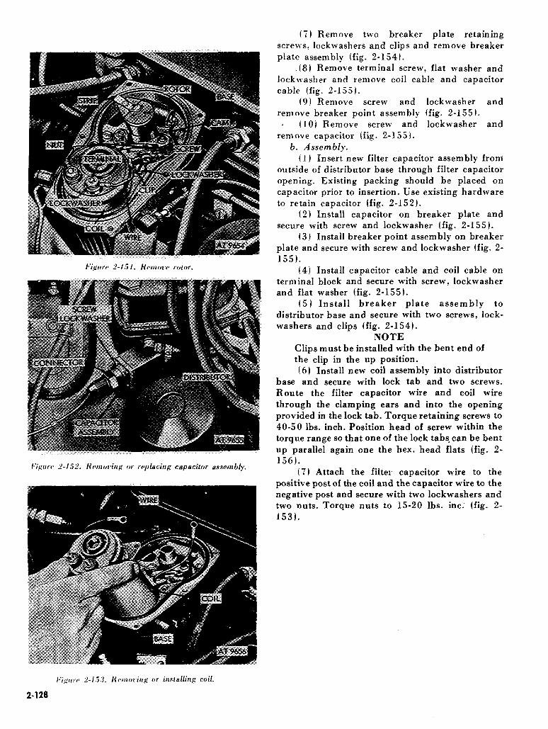
(7) Remove two breaker plate retaining screws, lockwashers an.d clips and remove breaker plate assembly (fig. 2-1543.
.(8) Remove terminal screw, flat washer and lockwasher and remove coil cable and capacitor cable (fig. 2-1551.
(9) Remove screw and lockwasher and remove breaker point assembly (fig. 2-1551.
. (101 Remove screw and lockwasher and remove capacitor (fig. 2-1551.
6. Assembly. (1) Insert new filter capacitor assembly from
outside of distributor base through filter capacitor opening. Existing packing should be placed on capacitor prior to insertion. Use existing hardware to retain capacitor (fig. 2-1521.
(2) Install capacitor on breaker plate and secure with screw and lockwasher (fig. 2-155).
(31 Install breaker point assembly on breaker plate and secure with screw and lockwasher (fig. 2- 1551.
(4) Install capacitor cable and coil cable on terminal block and secure with screw, lockwasher and flat washer (fig. 2-1551.
(5) Install breaker plate assembly to distributor base and secure with two screws, lock- washers and clips (fig. 2-154).
NOTE Clips must be installed with the bent end of the clip in the up position.
(6) Install new coil assembly into distributor base and secure with lock tab and two screws. Route the filter capacitor wire and coil wire through the clamping ears and into the opening provided in the lock tab. Torque retaining screws to 40-50 lbs. inch. Position head of screw within the torque range so that one of the lock tabs-can be bent up parallel again one the hex. head flats (fig. 2- 1561.
(7) Attach the filter capacitor wire to the positive post of the coil and the capacitor wire to the negative post and secure with two lockwashers and two nuts. Torque nuts to 15-20 lbs. inc. (fig. 2- 1531.
2-128

Z-71. Ignition Adjustment
a. General. Ignition timing is accomplished by four separate and consecutive procedures; breaker point gap adjustment, spring tension adjustment, timing by distributor positioning and precise timing by using an adapter, timing light and tachometer.
6. Breaker Point Gap Adjustment. (1) Crank the engine until the rubbing block
on movable breaker point rests on the peak of a cam lobe (fig. 2-156).
(2) Loosen stationary breaker point mounting screw and lockwasher (fig. 2-156).
(3) Adjust point gap with adjuster screw (fig. 2-156) until gap is 0.017 to 0.022 inch. Tighten contact mounting screw and lockwasher 5-20 lb. in.
NOTE If this procedure is not followed, the screw may loosen after several thousand miles, causing erratic engine operation.
c. Adjusting Spring Tension. (1) Attach spring gage to end of movable
contact and pull on gage at right angles to movable contact (fig. 2-157).
(2) Adjust spring tension (fig. 2-158) by positioning spring slot until desired tension is obtained and tighten terminal screw. Points should start to open with a pull of 17 to 20 ounces.
d. Approximate Timing by Distributor Positioning. Set distributor to approximate timing
as shown below: (I) Mark the position of the No. 1 spark plug
cable on distributor base (fig. 2-159) refer to figure 2-145 for No. 1 spark plug cable location. Adjust breaker point assembly (step b-l through 3 above) but do not install cap and cover assembly.
(2) Rotate crankshaft until rotor is positioned toward No. 1 spark plug cable mark and pointer on timing gear cover and notch on crankshaft pulley are aligned. Slowly rotate distributor coun- terclockwise until breaker points just start to open.
2-129

\-\I LIGHT ORD E5415
(3) Tighten distributor to adapter mounting screw to a snug fit (fig. 2-147).
(4) Install cap and cover assembly. This procedure alone is not adequate for good engine performance. Perform precise timing procedure, below.
e. Precise Timing. Refer to figure 2-160 for an illustration showing correct hcok-up for ignition timing. Operations below show procedures required for ignition timing, when distributor shaft has not been removed from engine during previous maintenance.
(1) Remove NO. 1 spark plug cable (fig. 2- 16 1) from spark plug, place timing light adapter on spark plug, and attach spark plug cable to timing light adapter.
(2) Connect timing light leads to timing light adapter, ground, and battery (fig. 2-161).
(3) Attach tachometer to primary connector and ground (fig. 2-162). Adjust engine idle to 450 to 500 rpm.
(4) With engine idling, direct timing light at timing pointer on timing gear cover (fig. 2-163).
(5) Slowly rotate distributor until timing pointer and crankshaft pulley notch are alined. When timing marks are alined, firing will take place at fro before top dead center of piston travel. When this alinement is accomplished, tighten distributor to distributor adapter mounting screw.
(6) After tightening mounting screw, recheck timing to determine that tightening has not disturbed alinement. Increase engine speed while directing timing light to notch and pointer. Notch should move away from pointer if distributor centrifugal advance is functioning. Disconnect all timing devices and install spark plug cable.
2-130

(5 1 Disconnect terminal nuts between spark plug cables and distributor. Remove cables.
h. Installation. Install spark plugs and spark plug cables by reversing removal operations. Refer to figures 2-164 and 2-165. Use new spark plug gaskets for installation. Torque spark plugs to 18- 20 lb. ft.
NOTE The lead and cable assembly must follow a sm 00th natural path without being twisted or stressed during or after assembly. Tighten cable nuts finger tight and then an additional 1 / 2 turn with a 3 / 4 inch open end wrench.
I~ic,‘uw 4-l 6.3. Checking timing using timing light.
Z-72. Spark Plugs and Spark Plug Cables
a. Removal. (1) Disconnect terminal nuts securing spark
plug cable to spark plugs (fig. 2-1641. (2) Remove all dirt from cylinder head recess
around spark plugs. (3) Use a deep socket wrench and remove
spark plugs (fig. 2-1651. Discard spark plug gaskets.
(4) Clean spark plugs (fig. 2-I651 on a spark plug cleaner and tester. Adjust gap to 0.027 to 0.030 in.
2-73. Description and Data
a. Description. The starting system consists of starting motor assembly, starter switch and connecting electrical cables. Figure 2-I 66 is a view of the starting system. The starting motor is a 24- volt, series wound, two-pole, four-brush, waterproof
Section XII. STARTING SYSTEM
unit. It is mounted on the right rear face of the flywheel housing. The starting motor assembly is equipped with an overrunning clutch to prevent damage to the starting motor at engagement with the flywheel or when engine speed is gre:iiLer than that of the starting motor.
2-131

b. data. Refer to table 1.-l &n-tabulated data.
2-74_. .Wg motor
a. Removal. (I) Remove front seats (para 2-1981. (2) Remove battery cover (TM 9-2320-218-
IO). (3) Remove battery ground cable (fig. 2-182). (4) Remove transmission cover plate (para 2-
199). (5) Remove starter cable (fig. 2-2381. (6) Remove two nuts, washers and clip
securing starting motor to flywheel housing. Remove starting motor and gasket. Discard gasket (fig. 2-167).
b. Installation. Clean starter mounting gasket surfaces on starter and flywheel housing before installing gasket and starter. Install starting motor on vehicle by reversing removal operations. Refer to figures 2-167, 2-166.
NOTE Use new gasket at installation.
2-75. Starting Switch
a. Removal. (J ) Disconnect battery ground cable (fig. 2-
1821. (2) Remove four screws, flat washers and
lockwashers securing starting switch bracket to floor (fig. 2-lfi8).
(3) Pull starting switch bracket away from floor and remove two nuts and lockwashers securing cables to cable terminals (fig. 2-169).
2-132

(4) Remove two screws and lockwashers b. Installation. Install starting switch by _
mounting starting switch to bracket and remove reversing removal operations. Refer to figures 2- switch (fig. 2-170 I. 170 back through 2-168.
Section XIII. GENERATING SYSTEM
2-76. Description and Data
a. Description. The 25-ampere generating system consists of generator, generator regulator, and connecting cables. Figure 2-171 is a view of the 25-ampere generating system. The generator illustrated is a two-brush, 25-ampere, 24-volt, waterproof unit, mounted on the left side of the engine. It is driven by two crankshaft driven V-belts. The generator regulator consists of three units : the voltage limiter which controls generator output voltage to prevent overcharging the batteries; the current limiter which prevents overloading the generator; and the cutout which prevents discharging of the batteries when generator output falls below the level required to charge the batteries. Other model vehicles may have the ho-ampere, 24-volt negative ground alternator system with built-in voltage regulators. Unlike the conventional direct current shunt generator, the alternator differs in that the ar- mature is called a stator and does not rotate. The rotor is the field. Internally mounted rectifiers in the 60-amp alternator convert the alternating current to direct current. The internally mounted regulator also controls the output of the alternator. In special applications the vehicle may include a loo-ampere or 180-ampere alternator, with ex- ternal regulator, and rectifier. Refer to special purpose kits (ch. 3 1.
b. Data. Refer to table l-l for tabulated data.
2-77. Generator Assembly (25-Ampere)
a. Removal. Procedures (11 through (61 below give operations for removing generator assembly and for removing pulley from generator.
(1 I Remove air cleaner (para. 2-441. Loosen generator and remove drive belts (para. 2-641.
(21 Using spanner wrench, disconnect generator-to-generator regulator cable at generator receptable (fig. 2-l 72 1.
(31 Loosen adjusting arm to cylinder block bolt. Remove adjusting arm bolt, lockwasher and flat washer from adjusting arm and .generator. Remove two mounting bolt nuts, lockwashers and flat washers from generator and mounting bracket. Remove mounting bolts and flat washers from generator and bracket Ifig. 2-173).
2-133

(61 Remove Woodruff key from slot in generator shaft.
b. Installation. Reverse removal procedures for installing generator. Use new cotter pins at in- stallation. When installing pulley on replacement generator, be sure spacer, Woodruff key, pulley and washer are properly seated. The following at- taching parts are to be torqued to the values shown :
Adjusting arm to cylinder bolt (3/s-16) 30-35 lb-ft. 7 / 16-14 47-56 lb-ft. Generator mounting bolt 58-60 lb-ft. Generator to mounting bracket nut 60-70 lb-ft.
NOTE The pulley nut on generators (Autolitel using cotter pin should be torqued to 35 lb- ft, and on generators (Delco Remyl not using cotter pin torque to 60 lb-ft. Refer to paragraph 2-66 for drive belt adjustment. Make sure generator bracket mounting bolts are torqued properly, loose bolts may cause damage to cylinder block.
2-78. Generator Regulator
a. Removal
CAUTION Disconnect battery ground cable. (1) Remove air cleaner hose (fig. 2-881. (2) Using spanner wrench, disconnect main
wiring harness connector at regular and pull plug out of receptacle (fig. 2-175).
: (31 Using spanner wrench, disconnect generator-to-regulator cable connector at regulator and pull plug out of receptacle (fig. 2-1761.
2-134

I.‘ipur~~ 2-I 77. Honovc generator regulator
with mounting brackets attached.
(4) Remove four mounting screws, lock- washers and flat washers and remove generator regulator with mounting brackets attached (fig. 2- 177).
b. Installation. Install generator regulator by reversing removal operation figure 2-177 back to 2- 175.
NOTE Torque attaching screws 9-12 lb-ft.
2-79. Generator-to-Regulator Harness
a. Removal.
(1) Using spanner wrench, loosen and remove
main wiring harness connector at regulator receptacle (fig. 2-175) to provide access to generator-to-regulator harness connector.
(2) Using spanner wrench, disconnect generator-regulator harness connectors at regulator receptacle (fig. 2-lib) ad at generator receptacle. Remove harness.
b. Installation.Install generator-to-regulator har- ness, using the follow’ing procedure:
i I) Install harness-to-regulator connector at the regulator receptacle. Tighten connector with spanner wrench.
(2 1 Install geneiator-to-regulator harness connector at regulator receptacle. Tighten con- nector with spanner wrench.
(3 1 Install generator-to-regulator harness connector to generator receptacle. Tighten con- nector with spanner wrench.
2-80. Generator-to-Regulator Harness Repair
. a. Disassembly. (1) Use suitable tool and pull three insert
plugs out of grommet (fig. 2-178) and unscrew grommet retaining nut.
(2) Slide nut and grommet away from receptacle. Unscrew spariner coupling nut and slide nut away from receptacle. Use suitable tool and push contact out of receptacle assembly (fig. 2- 179).
b. Assembly. Reverse removal operations for assembling generator-to-regulator harness receptacle.
2-81. Generator (Alternator) Assembly (60- Ampere
I~‘igcoc~ 2-l 7X. Konow plugs from grommet
and unscrew retaining nut.
2-135

a. General. Later model vehicles are equipped with the Leece-Neville, model 3002A, 60-ampere, three-phase ac alternator (10929868). These units provide more than twice the power of the 25- ampere dc generator, and use rectifiers to convert the alternating current output to direct current for the 2%volt dc vehicle electrical system. Six internal solid state rectifiers, mounted on a cooling fin
assembly for heat dissipation, are used for this purpose. Also internal to the alternator is the current and voltage regulator. The alternator is self- cooled and driven by%bree drive belts. It operates in ‘the speed range of 2,000 rpm to 8,000 rpm. Proper operation of the unit is indicated by the battery-generator indicator located on the dash panel.
b. Maintenance and Adjustment. Co\ventional general maintenance procedures for rotating machinery is specified. Periodic inspections of he V-belts are specified. Worn belts are to be replaLed as necessary and the correct degree of belt tension must be maintained at all times for proper operation. For alternator adjustment remove plug and adjust slotted screw to obtain 28 volts. (Refer to electrical troubleshooting table 2-4).
NOTE Counterclockwise to increase voltage. Apply sealer (FSN 8030-849-0071) to plug prior to installing.
c. Removal. Follow the general provisions for removal of the 25-ampere generator given in paragraph 2-77 a.
d. Cleaning, Inspection, and Repair. Refer to support maintenance for cleaning, inspection, and repair.
e. Installation. Follow the general provisions for installation of the 25-ampere generator given in paragraph 2-77 b.
Section XIV. BATTERIES AND LIGHTING SYSTEM
2-82. Description and Data
a. General. The batteries and lighting system are waterproofed. A circuit breaker in the light switch protects the lighting system from overload. All light circuits are controlled by the light switch on the instrument panel. Figures 2-180 and 2-181 are views of the lighting system. Cables are identified by numbered tags near the end of each cable.
b. Batteries. The 24-volt primary circuit is supplied by two 12-volt lead and acid-type storage batteries, connected in series. The batteries and connections are designed for under water operation.
c. Service Headlights. The sealed beam-type service headlights are mounted in the brush guard. High or low beam is selected by a foot-operated dimmer switch.
d. Blackout Driving Light. A single blackout driving light is mounted on the left front fender. This driving light supplies a diffused, low-intensity light beam, for use when the tactical situation prohibits use of the service headlights.
e. Blackout Marker Lihgts (Ml51, MlSlAl, MlSlAlC, and M718 Vehicles). Two light as- semblies, one mounted below each service head- light, serve the purpose of blackout marker lights.
f. Front Parking, Signal, ‘and Blackout Marker Lights (MlSlA2, M825, and M718Al Vehicles). The above lamp bulbs are housed in one
composite lighting assembly. A composite light assembly (fig. 2-181) (with the amber lens) is mounted to each front fender. The upper half of this light assembly houses the parking and directional turn signal bulbs. The lower housing contains the blackout marker light.
g. Blackout Stoplight (M151, MlSlAl, MlSlAlC and M718 Vehicles). The blackout
stoplight is mounted on the right rear corner of the vehicle body, above the service taillight.
h. Blackout Taillight, Blackout Stoplight, Service Taillight and Service Stoplights (MlSlA2, M825, and M718Al Vehicles). The above lamps
are all contained within one composite lighting unit. One composite unit is mounted at each rear
2-136

corner of the vehicle. The upper half of the unit houses the service taillight and service stoplight bulbs. They also serve as the left and right rear turn signal lights. The lower portion of the composite unit contains the blackout marker and stoplight bulbs.
i. Blackout Taillight. Service Taillight, and Service Stoplight (M151, MlSlAl, MlSlAlC,
and M718 Vehicles). The blackout taillight,. service taillight and service stoplight assemblies are mounted in the lower rear corners of the vehicle body. The upper half of the assembly houses two lamp units, a service taillight, a service stoplight and performs the left and right turn signal function. The lower half houses a single lamp unit, a blackout taillight.
2-137

2-138

j. Trailer Coupling Electrical Receptacle. A twelve-terminal receptacle is mounted on the left
rear corner of the body of the vehicle. This receptacle provides a means of connecting the electrical units of a towed trailer to the vehicle electrical system. When connected, trailer lights are controlled by the towing vehicle light switch.
k. Directional Turn Signal Lights. Directional
turn signal lights are mounted on the left and right front fenders to provide turn signal directions,and
are controlled by means of a control handle
mounted on the steering column. 1. Directional Control Assembly. A directional
control assembly with control handle to activate the directional turn signal lights is mounted on the left side of the steering column. In its extreme upper
position, the control handle actuates a flasher that switches all directional lights on and off to serve as
a hazard or emergency warning. m. Distribution Box. Flashing of the signal
lights is accomplished by a flasher mechanism
located in the distribution box (fig. 2-2 18) mounted on the firewall beneath the front panel. On later model vehicles this function is performed by a solid state flashing device (fig. 2-219).
n. Data. Refer to table 1-1 for complete data.
2-i3. Batteries
a. General. For service instructions on adding water, cleaning, performing specific gravity test, and charging batteries, refer to TM 9-6140-200-15.
b. Removal. II) Remove passenger seat (para 2-198) and
battery compartment cover (refer to TM 9-2320- 218-10).
(2 1 Loosen battery ground cable terminal bolt nut and remove ground cable terminal from negative post of right battery (fig. 2-182).
(3) Loosen battery cable terminal bolt and nut and remove cable terminal from positive post of left battery (fig. 2-I83).
NOTE Do not pry on terminals. Use lifter FSN 5120-243-1039.
(4) Loosen battery connector cable terminal bolt nuts and remove battery connector cable from positive post of right battery and negative post of left battery (fig. 2-182).
(5) Remove four battery holddown nuts and flat washer. Remove two holddown frames (fig. 2-
183). (6) Lift batteries from compartment.
CAUTION Do not use a lifting strap that connects to battery posts.
c. Installation, Install batteries by reversing removal operations.
CAUTION Prior to assembly of battery cables, make
sure all switches are “OFF”. After installation, check battery polarity. Turn ignition switch on. If battery-generator indicator
registers no reading, battery or batteries are
reversed : correct installation as necessary. If in- dicator registers, batteries are correctly installed.
NOTE Be sure batteries are clamped down firmly to avoid damage from bouncing.
2-84. Battery to Starting Switch Cable (Positive)
a. Removal. (1) Remove passenger seat (para 2-198),
battery cover (TM 9-2320-218-lo), and battery ground cable (fig. 2-182).
(2) Loosen terminal nut and remove positive cable from left battery and remove terminal from
cable end (fig. 2-183). (3) Remove nut, lockwasher and screw, and
rubber covered clamp at inside of body side panel sill (fig. 2-184).
(4) Remove snap clips securing cable to inside
of body pane1 sill (fig. 2-185 ). (5) Remove nut and lockwasher from screw
securing clamp to firewall. Remove rubber covered
clamp from screw on firewall inside passenger
compartment. Remove clamp from cable (fig. 2-
185 and 2-186).
2-139

securing clamps and cable to firewall passenger compartment above tunnel Remove clamps from cable (MlSlAl, M M 1 SlAlC, M825, M’718 and Mi’18Al) 186).
I‘i,~.rtrr~ _‘-l11.5. Nrwlot? .srl;lj~ clips ilf body pncl sill
and clamp on firctoall (Ml.51 only).
(6) Remove two screws and lockwashers inside cover.
151A2, (fig. 2-
(7) Remove two screws and lock! Nashers securing clamps and cable to right and left side of firewall tunnel. Remove clamps from cable (Ml51 only) (fig. 2-187).
(8) Remove nut, lockwasher and screw securing clamp and cables to firewall above clutch pedal. Remove rubber covered clamp from cables (fig. 2-188).
(9) Remove starting switch bracket and remove cable from terminal (fig. 2-169).
( 10) Thread cable out of grommet at battery compartment (fig. 2-189).
(11) Thread cable out of grommet at both sides of transmission tunnel (M 151 only).
6. InstalZation. Install battery to starting switch cable by reversing removal operations.
2-85. Service Headlights
a. Adjustment. Refer to figure 2-190. (1) Position vehicle on a level floor with no
load in vehicle. Headlights should be 25 feet from a smooth vertical surface. Inflate tires to proper pressure. Refer to vehicle data plate or table l-l.
(2) Measure centerline of headlights from floor; draw a horizontal line at that height on the flat surface. Draw a second line parallel to and 3” below first line.
(3) Draw a vertical line intersecting the first two lines at the projected centerline of the vehicle.
(4) Measure distance between two headlight centers, then divide distance equally on both sides
of centerline. Draw a vertical line at these points. intersecting the first two lines.
(5) Turn headlights on and select high beam. Cover one light while adjusting the other.
I~‘igtr rca 2-l HH. Kcrnovr clamp jrrom firewall
above clutch pedal.
2-14il

(6) Turn adjusting screws in or out until beam is adjusted to a pattern as near as possible to that shown in figure 2-190. Adjust other headlight in same manner.
b. Replacement of Sealed Beam Lamp. (1) Remove three screws and lockwashers.
Remove lamp retainer (fig. 2-191). (2) Pull lamp out of recess. Pull electrical
connectors from housing. Remove lamp unit (fig. 2-
192). NOTE
Connectors are molded unit. Do not remove.
c. Removal of Headlight
to sealed beam
Assembly.
(1) 193).
(2) securing Remove
(3)
Disconnect electrical connectors (fig. 2-
Remove three nuts and lockwashers headlight assembly to brush guard.
headlight assembly (fig. 2-193 ). Disassemble headlight assembly as shown
in figure 2-194.
d. Installation of Headlight Assembly. Install headlight assembly by reversing removal operations.
NOTE Whenever a new headlight assembly is installed in the vehicle it is necessary that headlights be adjusted (fig. 2-190).
Z-86. Blackout Driving Light
a. Removal of Sealed Beam Lamp Unit. (I) Rem_ove three screws securing door
assembly (fig. 2-195). (2) Pull door and lamp assembly from light
housing and separate cable connectors (fig. 2-196). (3) Remove three lamp retaining springs and
remove sealed beam lamp (fig. 2-197). b. Installation of Sealed Beam Lamp
Unit. Install sealed beam lamp unit by reversing removal operations.
c. Removal of Blackout Driving Light Assembly.
(1) Grasp cable at connectors and pull, separating male and female connectors (fig. 2-198).
(2) Remove nut and lockwasher securing blackout driving light assembly to bracket (fig. 2-
199).
2-141

HOLE - y FLOOR
25 - FEET
EQUA
L,lNE
‘ING ‘$ OF HEADLAMP
LINE OF ADJUSTMENT
rDLAMP
2-142

d. Installation of Blackout Driving Light Assembly. Reverse removal operations in c above.
NOTE Figure 2-200 illustrates mounting of blackout driving light and composite lighting assembly on M151A2, M825, and M 7 18A 1 vehicles.
2-87. Blackout Marker Light (M151, MlSlAl, MlSlAlC, and M718 Vehicles)
a. Replacement of Blackout Marker Lamp. (1) Remove two screws and remove door
assembly (fig. 2-201). (2 1 Grasp lamp, turn counterclockwise and
remove. Install new lamp. Install door assembiy and screws (fig. 2-202).
b. Removal of Blackout Marker Light A.ssembly.
(1) Grasp cable at connectors and pull, separating male and female connectors (fig. 2-203).
(2) Remove nut and lockwasher securing
blackout marker light assembly to bracket (fig. 2- 203 ).
c. Installation of Blackout Marker Light Assembly. Reverse removal operations above.
2-88. Front Parking, Directional Signal, and Blackout Marker Composite Lights (MlSlA2, M825, and M718Al Vehicles)
a. Replacement of Lamps. (1) Loosen five screws securing door to light
housing, (fig. 2-204). (2) Remove door (fig. 2-205) and preformed
packing from housing. Press bulb in and turn counterclockwise.
(3) Install another bulb. Properly position performed packing and door to housing and secure door by tightening five screws.
b. Removal of Composite Light Assembly. (I) Disconnect three connectors at the front
composite light assembly (fig. 2-193). (2) Reach to underside of front fender and
Z-143
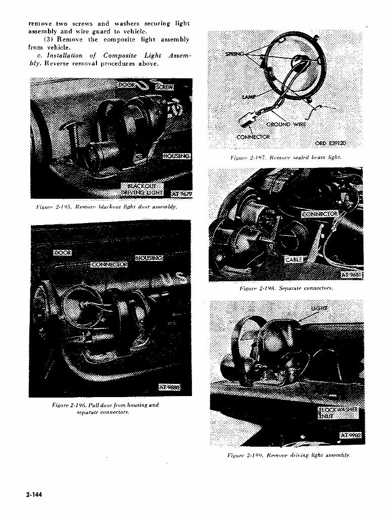
remove two screws and washers securing light assembly and wire guard to vehicle.
(3) Remove the composite light assembly from vehicle.
c. Installation of Composite Light Assem- bly. Reverse removal procedures above.
I~‘ig~rrrc~ 2-I YY. Krmovc drking light assembly.
2-144

Iq’i;rurca P-200. Krmoving or insialling blackout headlamp
on MlSlA2. M825. and M718Al vehicles.
I:igrrrra 2-201. Krrnow lhclrr~u~ marker door a.ssem hly.
(M151. M151Al. MlSlAlC and M718 r~c~lricl~ts
I:iguw P-20.7. Kwnow blackoul marker light assembly
(M1.51. MlSlAl. MlSlAlC. and M71H L’r~lriclwl.
2-89. Tail and stoplight Assemblies Blackout Service (M151, MlSlAl, MlSlAlC, and M718)
a. Replacement of Lamps. (I) Remove six screws securing door to light
housing. Remove door (fig. 2-206). (2) Press lamp in and turn counterclockwise
and remove lamp (see fig. 2-207 ). Install new lamp. Install door and screws.
b. Taillight Assembly Removal. (1) Disconnect three cable connectors.
Remove two screws and lockwashers securing the taillight assembly (fig. 2-208).
(2) Remove taillight from opening in body (fig. 2-209).
c. Taillight Assembly Installation. Reverse rem oval operations above.
d. Replacement of Lamp. (1) Remove the two screws securing the
blackout signal lamp door assembly (fig. 2-206) to the blackout door gasket.
(2) Remove the door assembly and gasket. (3) Press in on the blackout lamp and turn
counterclockwise to remove from socket. Install new lamp. Install gasket, door assembly and two screws.
e. Blackout Stoplight Removal. (I 1 Disconnect cable connectors. Remove
screw and lockwashers securing the blackout stoplight from the right rear corner of the vehicle
body. (2) Remove the blackout stoplight.
2-145

f. Blackout Stoplight Installation. Reverse removal operations above.
2-90. Blackout Taillight, Blackout Stoplight,
Service Taillight and Service Stop-
lights (MlSlA2, M825, and M718Al
Vehicles)
a. Replacement of Lamps. ( 1) Loosen six screws securing door to light
housing (fig. 2-210).
(2) Remove door (fig. 2-211) and preformed packing. Press bulb in and turn counter-clockwise to remove.
(3) Install new bulb. Position preformed packing and door assembly in place to light housing. Secure door by tightening six screws.
2-146

I“i0rr.v 2-2/N. KflmOw (ailliglrl frorrr r,pning irl /wcl~
(M1.51. MlSlAl. M151A’lCetrd M71Xl.
6. Removal of Composite Light Unit. (1) Remove three screws and lockwashers
securing light assembly cover plate to vehicle body (fig. 2-212).
(2) Remove two screws and lockwashers securing rear composite light. Separate electrical connectors (fig. 2-2 13 1 and remove composite light unit from vehicle.
c. Installation of Composite Light Unit. Reverse removal procedures above.
2-91. Directional Signal Lights (M151, MlSlAl, MlSlAlC and M7I8)
NOTE The directional signal lamps on M151A2, M825, and M718Al vehicles are in- tegrated into the composite light assem- blies. Refer to paragraph 2-88.
a. Replacement of Lamp. Refer to figures 2-224 and 2-215.
(1 I Remove two screws and washers from the turn signal lens.
(2) Remove the lens and gasket from the turn signal body.
(3) Press lamp in and turn counterclockwise to remove from socket. Install new lamp. Install gasket, lens, screws and washers securing lens to turn signal body.
b. Directional Signal Light Removal. ( 1) Disconnect cable connectors. Remove one
turn signal lamp mounting screw and two washers securing the directional turn signal light assembly to the vehicle fender (fig. 2-216).
(2) Remove directional signal light. c. Directional Signal Light Installation. Reverse
removal operations above.
2-92. Directional Turn Signal Control Assembly
a. Removal. (11 Disconnect cable to flasher assembly (fig.
2-217).
(2) Remove clips securing cable to steering column.
131 Remove screw and nut from clamp on stccrina colnnl n and remove control assern bly.
/~'iptrrf~ I- ‘?I 0. Nwttwittp ttr itt.stirllittg door
IO rear light housittp (Ml SlA2. M1125. and M71RAl r~r*ltic~lr:v/.
If’iprrc Z-211. Kctnwittg or ittslallittg war lamp bulbs
(MlSlA.?. M82.5. and M71HAl vehicles).
I~‘igrrrc 2-212. Removing or inslal~ing t-ear cover plate
(.M151A2. M825. and M7lHAl vehicles). 2-147

I*‘iirtrr~~ 2-2 1.7. Removing or installing rear composite light unit (M151A.Z. MW.25. and M718AI whiclcsl. _. .
I”i~~urc~ 2-214. Remove directional turn signal lens
(M151. M151Al. M151AlC. and M718 Vehicles).
Figure 2-215. Replace directionalsignal lamp
(M15i. M15lAl. M151AlC. and M718 vehicles).
2-148

NOTE On vehicles equipped with a solid state flasher, the control assembly is removed in the same, manner except the cable is disconnected at the control assembly.
b. InstalZation. Install directional control assembly by reversing removal operations.
NOTE If control assembly is replaced, install only late model directional control. Refer to paragraph 2-94.
c. Replacement of Lamp. Remove lens signal light from control handle and remove lamp. Replace lamp and install lens signal light on control handle (fig. 2-2 17).
2-93. Distribution Box or Solid State Flasher
a. Removal of Distribution Box (fig. Z-218). (1) Remove directional control harness and
main wiring harness from distribution box. (2) Remove two screws and washers securing
distribution box to firewall. Remove distribution box.
b. Installation. If distribution box is to be
replaced, install late model solid state flasher assembly. Refer to paragraph 2-94.
c. Removal of Solid State Flasher Assembly (fig. 2-219).
(I) Remove cable assembly from flasher
assembly. (2) Remove two screws and washers securing
solid state flasher assembly to firewall. Remove flasher assembly.
d. Installation of Solid State Flasher Assem- bly. Reverse removal operations above.
2-94. Solid State Turn Signal Kit
a. Removal of Old Parts.
(1) removal steering
(21 rem oval
(31 harness.
Remove control assembly by completing operations in paragraph 2-92. Retain
column clips. Remove distribution box by completing operations in paragraph 2-93. Remove old terminals from front wiring
2-149
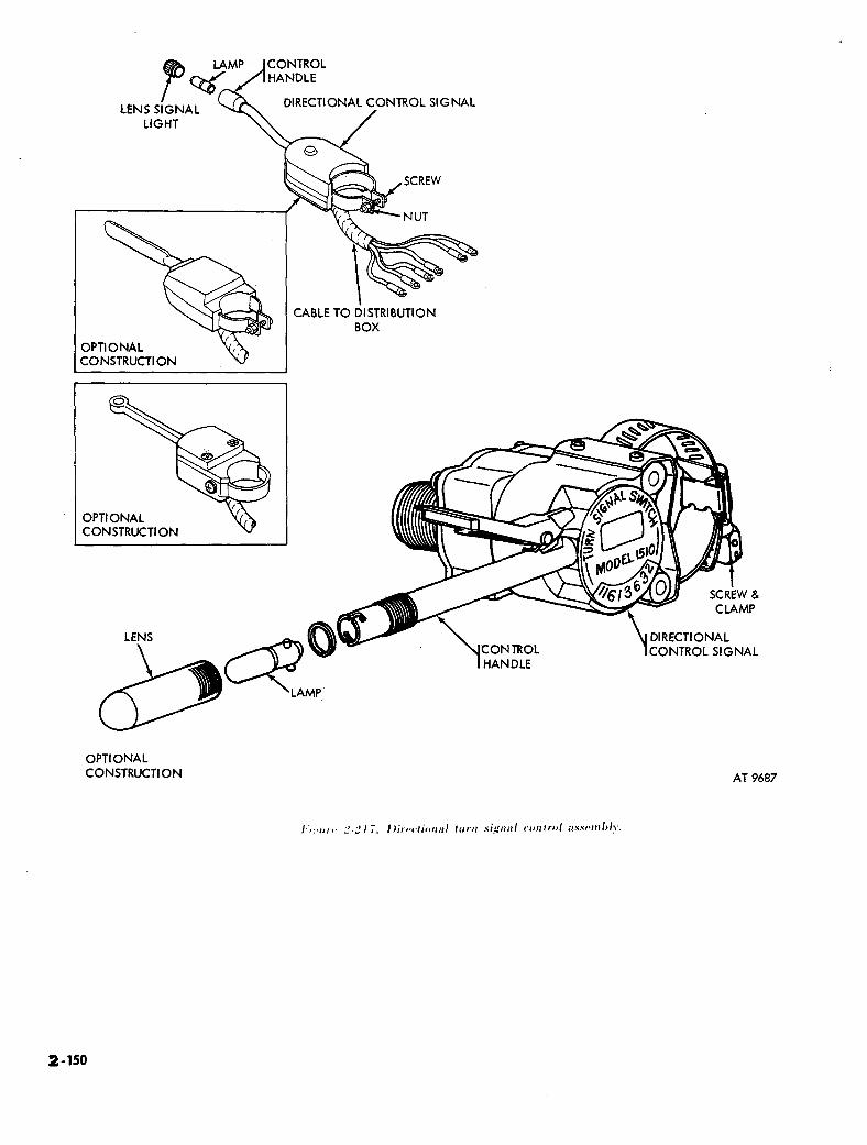
P LENS SIGNAL
DIRECTIONAL CONTROL SIGNAL
LIGHT
CABLE TO DISTRIBUTION
CONSTRUCT1 ON
OPTI ONAL CONSTRUCTION
DIRECTIONAL LENS
OPTI ONAL CONSTRUCTION
CONTROL ~CONTROL SIGNAL HANDLE
AT 9487
I.‘,: ‘,,, ,. “.” \ ;. /,;,?,~r;,,,,;,l /rtrtt s;,ipt;t/ c.i~rtI,.t~/ itswtliJl~. -_
2-150

SOLID STATE FLASHER
SCREW AT 9690
(I) Install six connectors to front wiring harness leads.
(2) Mount solid state flasher assembly using two screw and lockwasher assemblies in the location from which the distribution box was removed.
(3) Mount directional control switch assembly to steering column.
(4) Connect new cable to directional control assembly.
(5) Route cable along steering column and secure to column using clips removed in a (11 above.
(0) Connect cable to solid state flasher asscm hly.
(i) Connect cable ground to flasher assembly mounting screw nearest the connector, placing an internal-external tooth washer between ground terminal and mounting bracket.
(8) Connect control assembly cable leads to front wiring harness leads, matching wire numbers.
2-9s. Trailer Electrical Connector Receptacle
a. Removal. Refer to figures 2-220 and 2-221. { 1) Pull connectors from receptacle. (2) Remove screws, nuts, and lockwashers
securing trailer electrical connector receptacle. (3 ) Remove trailer electrical connector
receptacle. b. Installation. Reverse removal operations
above. NOTE
Both cables with No. 90 tag (fig. 2-222) are ground cables. Install under the lock- washer of the upper left and lower left receptable attaching screws. Be sure the terminal lead and body panel metal are clean to obtain a good ground.
2-96. Repair of Electrical Cables
All repairs to electrical cables will be made in accordance with TB ORD 650. Terminals of braided cables will not be repaired. Figures 2-223 and 2-224 show operations for exposing the male terminals. Damaged terminals will be removed and new terminals soldered or crimped in place. To expose female terminals of cables, simply pull the rubber waterproof cap toward center of the cable away from the terminal.

(I rubber
(2 2-2241
(3
1 Use suitable tool and pull terminal out of cap (fig. 2-223).
) Pull C-type retainer washer off cable (fig.
1 Slide rubber cap off cable, exposing terminal for repair (fig. 2-224).
2-97. Electrical Cables
a. General. Each electrical cable (except the spark plug cables) is identified by a numbered metal tag at each end of the cable. All cables in a single circuit are identified by the same number: however, when cables are connected through more than one connector, they may connect to a different numbered terminal at each connector. Refer to paragraphs 2-19 through 2-25 when replacing cables.
b. Circuit Identification. Paragraphs 2-19 through 2-25 list each circuit number in the
electrical system and briefly trace each circuit. A point-to-point check for circuit continuity can be made. using a battery-operated test light, and a voltmeter equippped with long cables and suitable probes.
2-98. Chassis Wiring Front Harness
a. Description. The electrical wiring of the vehicle is housed in two major harness assemblies. The front assembly carries current to all electrical units located in and forward of the dash panel. The rear assembly carries current to the fuel pump and fuel gage sending unit. and all electrical units located in the rear of the vehicle. The two harnesses are connected behind the dash panel. Harness assemblies are waterproofed and each cable except the spark plug cable is identified by a numbered metal tag at each end. All cables is a single circuit are identified by the same number. Each harness assembly can be removed for repair or replacement without removing the other. It is important to determine whether the harness assembly will be repaired or discarded before removal from the vehicle. If the harness assembly will be repaired, some connectors must be disassembled before the connections can be cut from the cables eliminating this disassembly procedure.
I,$/ W 2-22.‘:. I’rrll 1fTnlinel oul of rubber cap.
N V’I’E;
The M 151A2 vehicle (this includes MlSlA2, M825, or M728Al models1 has not electrical fuel pump mounted in the fuel tank. Instead, a mechanical fuel pump is mounted at front right side of engine.
b. Removal of Front Wiring Harness (Ml51, Ml51Al. MlSlAlC and M718 Vehicles). Figure 2-225 shows the front harness assembly and its position in the vehicle.
(1) Remove front seats (para 2-1981, battery compartment cover (TM 9-2320-218-10) and transmission tunnel cover (para 2-1991
2-152

(2) Loosen nut and lift battery ground cable off battery terminal (fig. 2-182).
WARNING Be sure cable does not come in contact with battery terminal at any time. (3) Pull connectors from right and left
headlights and blackout marker light. Remove screw, nut and lockwasher securing ground cables and cable assembly clips (fig. 2-203).
CAUTION Do not remove connectors by pulling on cables. This could cause damage to in- sulators and connectors. (4) Remove connectors from blackout driving
light and directional turn signals (fig. 2-195). (5) Remove screw, nut, and lockwasher
securing each ground cable clip to fender. Remove clips from ground cable (fig. 2-226).
(6) Use spanner wrench and unscrew cable No. 5 at generator regulator (fig. 2-227).
(7) Separate connector in horn switch cable (fig. 2-228).
(8) Remove cable assembly out of three clips on left side of engine compartment (fig. 2-229).-
(9) Unscrew cable connector securing cable to ignition distributor (fig. 2-146).
(10) Remove connector (fig. 2-146). (11) Remove connector from fuel pump safety
switch (oil pressure safety switch) (fig. 2-67).
2-153

( 12) Remove connectors from oil pressure transmitter unit (fig. 2-67).
(13) Remove connector from horn (fig. 2- 285).
( 14 1 Remove connector from temperature transmitter unit (fig. 2-146).
(15) Remove harness assembly from five clips on right side of engine compartment (fig. 2-230).
( 16 1 Loosen two screws securing choke control cable and cable housing. Remove housing to vent tube clip. Remove housing and cable from carburetor (fig. 2-231).
( 17) Remove vent tube nut from fitting. Full vent tube through grommet (fig. 2-232).
NOTE A rubber tubing is connected to vent tube on opposite side of grommet. (18) Remove two grommet retainer inounting
screws and !ockwashers and remove grommet retainer. Pull grommet free of firewall and pull it off choke cable housing. Push choke cable housing through firewall (fig. 2-232).
(19) Remove four screws and lockwashers securing instrument cluster to dash panel and pull instrument cluster away from panel (fig. 2-233).
(20) Unscrew nut securing speedometer cable housing to speedometer (fig. 2-234).
(21) Pull connectors from instruments and gages, and remove instrument cluster (fig. 2-235).
NOTE Numbers shown indicate circuit numbers. (22) Separate the connectors between front
harness assembly and rear harness assembly (fig. 2- 236) (cable Nos. 27,28,24, 23,22 and 2 1).
(23) Separate cable connectors from three circuit breakers (fig. 2-23 7).
(24) Remove transmission tunnel cover and remove nut and lockwasher securing starter cable and fuel pump safety switch (oil pressure safety switch 1 cable to starter. Remove cables from starter terminal (fig. 2-238).
2-154

2-155

(25) Unscrew cable connector behind light switch. Pull connectors from ignition switch (see fig. 2-239).
(26) Pull connectors from stoplight switch. Stoplight switch is located in bottom of master cylinder (see fig. 2-240).
(27) Remove four screws and lockwashers securing dimmer switch to floor panel (see fig. 2- 241 ).
(28) Pull dimmer switch away from floor. Pull connectors from dimmer switch (see fig. 2- 242).
(29) Loosen two screws in back of starter switch and remove two front screws switch to floor panel (see fig. 2-243).
(30) Pull starter switch away from floor. Remove two nuts and lockwashers securing electrical connectors (see fig. 2-244).
(31) Remove connectors at end of harness assembly.
(32) Push front harness assembly through hole in firewall (see fig. 2-245).
(33) Push front harness assembly out from inside of vehicle (see fig. 2-246).
c. Installation of Front Wiring Harness (MlSl. - M151Al. MlSlAlC. and M718). procedures in b above.
NOTE The M 151A2 vehicle (this includes M151A2. M825, or M718Al models) has not electrical fuel pump mounted in the fuel tank. Instead, a mechanical fuel pump is mounted at front right side of engine.
d. Removal of Front Wiring Harness of Ml 51 AZ. M82.5, and M718Al Vehicles. Figure 2- 18 1 shows the front harness assembly and its position in the vehicle.
(1) Remove front seats (para 2-198), battery compartment cover (TM 9-2320-218-10) and transmission tunnel cover (para 2-199).
(2) Loosen nut and lift battery ground cable off battery terminal (fig. 2-182).
WARNING
Make sure cable does not contact battery ground terminal at any time while front harness is being removed. (3 ) Disconnect I2 electrical connectors at two
front headlights and two composite light assemblies (fig. 2-193).
(4) Remove screw and two lockwashers from retaining clip securing ground at right front fender (fig. 2-193).
(5) Pull connector at blackout driving light, and remove screws from retaining clips securing cables to left front fender. Separate clips from cables (fig. 2-226.)
(6) Remove screw and two lockwashers securing ground cable terminal to firewall. Place lockwashers and screw back into position since they also secure brake and clutch pedal assembly to driver’s side of firewall.
(7) Separate electrical wiring from 60 ampere generator.
(8) Disconnect horn switch connector (fig. 2- 228).
(9) Remove wiring harness assembly from strap at air cleaner bracket and three clips (fig. 2- 229).
(10) Unscrew cable coupling from distributor and ignition coil assembly (fig. 2-247). Separate coupling from cable.
(I 1) Disconnect connectors at oil pressure
transmitter (fig. 2-67) and temperature transmitter units (fig. 2-146).
(12) Disconnect the two connectors at horn assembly (fig. 2-247).
(13) Remove windshield washer hose from the one corner clip so right side of wiring harness can be removed from all five clips (fig. 2-247) in engine compartment.
2-156

(14) Loosen two screws and remove clip that secures choke cable assembly to carburetor and vent line (fig. 2-231).
(2) Loosen nut and lift battery ground cable . off terminal (fig. 2-182).
(15) Remove two screws and lockwashers securing grommet retainer. Remove retainer (fig. 2- 248).
( 16 1 Pull rubber grommet away from firewall, and push choke cable and its housing through firewall.
(17 1 Remove four screws and lockwashers securing instrument cluster assembly to dash panel (fig.’ Z-233).
(18) Pull instrument cluster assembly away from dash panel, and disconnect speedometer cable nut and its housing from speedometer gage (fig. 2- 234).
(19) Disconnect all connectors to various other gages on instrument cluster. Remove in- strument cluster (fig. 2-235 1.
(20) Disconnect front and rear wiring harness connectors apart (fig. 2-236).
(2 1 Reach inside just to left of cluster opening l~‘i,gtcrc~ 2-2.3X. Kcmove transmission tunnel cover
and disconnect four connectors for the two circuit and remove cables from starter.
breakers (fig. 2-249). (22) Disconnect connector coupling at light
switch and four connectors at the ignition switch (fig. 2-239).
(23) Separate two connectors for stoplight switch (connectors are located near top of clutch pedal).
(24) Separate connector at windshield wiper motor (fig. 2-250).
(251 Remove coupling connectors at the directional control unit on the steering column (fig. 2-250).
(26) Disconnect the connector at the flasher unit located up against driver’s side of firewall.
e. Installation of Front Wiring Harness (MlSlA2, M82.5, and M718Al). Install front
wiring harness by reversing removal procedures in
I**ig!tcrca 1-2.70. Unscrew connector behind light switch
and puff connectors from ignition switch.
d above.
2-99. Rear Chassis Wiring Harness
a. Removal of Rear Wiring Harness Assem - bly. Figure 2-251 shows the rear harness assembly
and its position in the vehicle. It is not necessary to remove the front harness assembly if only the rear harness assembly is defective. Refer to procedures ( 1) through ( 13) below for operations necessary to remove the rear harness assembly.
NOTE Figure 2-252 illustrates the rear harness assembly and its position in MlSlA2, M825, and M718A1 series vehicles. (1) Remove front seats (para 2-1981, battery
compartment cover (TM 9-2320-218-10) and _ transmission tunnel cover (para 2-199).
Z-157

I:igttrc* Z-2,11. Remove ditntner switch from floor panel. kigtrrr~ Z-_).C,i. Kc~tnove electrical connectors
/ rotn skirter switc 1. I
I~igrtrc~ 2-2.12. IWI cottnectt~r.7 from switch.
I*‘i~*ure 2-24.3. Disconnect starter switch from floor panel.
2-158

2-159

I*‘iptrr<~ 2.2 1,~. Krrnor+zg or installing grommet and its retainer to firewall on M151A2. M8.25. and 117l8A I ~Aiclm.
connecting circuit breaker connrctors
on MI51A2. M825. and II 7 1::. I I r,r-hi&s. I.‘i,tiorrs 2-2.iO. Ihconnccting or connecting electrical connector
at windshield wiper motor.
2-160

AT 9703
2-161

AT24182
2-162

2-163

Be sure cable does not come in contact with battery terminal at any time. (3) Refer to figures 2-234 through 2-236 and
remove instrument cluster. Grasp cables and pull, separating male and female connectors between front and rear harness assemblies (cables Nos. 27, 28, 24, 23, 22 and 21).
NOTE On M151A2 vehicles (MlSlA2, M825, and M718Al) rear harness cables con- necting with front wiring harness are number 24, 21, 22-461, 22-460 and 23.
(4) Pull connectors at fuel pump and fuel gage sending unit (fig. 2-253).
NOTE M151A2, M825, and M718Al vehicles have a mechanical fuel pump mounted to engine right side, hence these models require no electrical connection for the fuel
pump. (5) Remove screw, nut and lockwasher se:
curing cable clip and cable to left inner body rail. Remove clip from cable (fig. 2-254).
(6) On M151, MlSlAl, MlSlAlC, and M718 vehicles, remove grommet from body left inner rail and push fuel pump and fuel gage send- ing unit cables through hole. On MlSlA2, M825, and M718A vehicles, remove grommet and push fuel gage sending unit cable through hole (fig. 2- 255).
(7) Attach a piece of wire seven feet long to end of harness assembly. Attach other end of wire to chassis part to prevent accidentally pulling loose end of wire into frame rail. This wire will be used to pull the new cable assembly through the length of the body side rail (fig. 2-256).
(8) Remove grommet and push cable assembly into left frame side rail (fig. i-257).
(9) Disconnect connectors at trailer electrical receptacle. Loosen and remove two nuts and lock-
washer attaching ground wires. Remove ground wires. Remove wire from clip (fig. 2-258).
(10) Disconnect connectors at left taillight (fig. 2-258) (M151, M151A1, MlSlAlC, and M 7 18 vehiclesl. Remove three screws and lock- washers securing cover plate (fig. 2-2121, and disconnect four connectors to rear composite light assembly (fig. 2-213) (MlSlA2, M825, and M718Al vehicles).
I.iptrrv 2-260. I)ismrrncwt conrtrctor at blackout stoplight.
(11) Remove cable from clip and disconnect the connectors at right taillight (fig. 2-259) (M 15 1, MlSlAl, MlSlAlC and M718 vehicles). Remove cable from clip. Remove cover plate as described in ( 10 1 above, and disconnect four connectors at rear left composite light assembly (MlSlA2, M825, and M718Al vehicles).
t12) Remove cable from clip and disconnect connectors at blackout stoplight (fig. 2-260) (M151, MlSlAl, MlSlAlC, and M718 vehicles).
2-164

t I 31 Remo1.e grommets from body left and right inner side rails and push cables through holes
(fig. 2-20 1 1.
NOTE When forward end of cable is pulled free of boxed inner side rail, unhook wire from cable as attached in (71 above. Leave wire in position is side rail to facilitate in- stallation of new rear cable assembly. ( 141 Remove cable from clips and pull cable
assembly from frame inner side rail (fig. 2-262). b. Installation. Install rear wiring harness by
reversing removal procedure.
,INNER BODY RAIL
ORD El0325
Section XV. INSTRUMENT PANEL, GAGES, SWITCHES SENDING UNIT AND HORN
2-100. General
a. Instrument Cluster. The speedometer (with odometer), battery-generator indicator, fuel level gage, temperature indicator, oil pressure indicator, headlight high beam indicator, and two instrument panel lights are mounted in the instrument panel. The panel, together with mounted instruments and lights, is referred to as the instrument cluster.
b. Switches. The vehicle contains the following switches, for which information or data is provided in this section or as indicated:
(1) Lighting switch (para 2-111). (21 Foot headlight dimmer switch (para 2-
112).
(3) Stoplight switch (para 2-113). (4) Fuel pump safety switch (oil pressure
safety switch) (para 2-37).
(5) Starting switch (para 2-74).
(6) Ignition switch (para 2-l 10 1.
(7) Horn switch (para 2-1 I?).
(8) Directional signal switch (para 2-l 18).
c. Sending Unit. The fuel level sending unit is mounted in the top of the fuel tank and transmits the fuel level in the tank to the fuel gage in the instrument panel.
d. Horn. The horn is of the vibrator type, electrically operated through the horn switch, and is waterproofed. The horn is mounted on the right side of the firewall in the engine compartment and is connected to the horn button (switch) by one cable. It is protected by the horn circuit breaker, which is mounted behind the instrument panel to the left of the instrument cluster.
e. Directional Turn Signal. The directional signal is located on the left side of the steering column. This directional signal is composed of lamp, control handle, and flasher unit.
f. Circuit Breakers (MISI, kfISIAI, MlSlAlC, and M718 vehicles). Four circuit
breakers protect circuits in the electrical system. Three are mounted behind the instrument panel and to the left of the instrument cluster. The top
2-165

circuit breaker protects the temperature indicator, fuel gage, and the oil pressure gage. The middle circuit breaker protects the fuel pump circuit, and the bottom circuit breaker protects the horn circuit. The fourth’ circuit breaker, protecting the light circuit, is an integral part of the light switch.
g. Circuit Breakers on Ml5lA2, M825, and M718Al Vehicles. Two circuit breakers, both mounted inside the dash just left of instrument cluster (fig. 2-249 1, protect various electrical circuits. The top one protects the temperature indicator, fuel gage and oil pressure gage. The bottom one protects the horn circuit. A third breaker, integrated into the light switch assembly, protects the vehicle’s lighting circuitry.
h. Cable Numbers. Standard circuit or cable numbers are used throughout the electrical system, where possible. The cable numbers are stamped on small metal tags attached near both ends of each cable. Refer to figure 2-43 for correct identification of cables.
Z-101. Instrument Cluster
CAUTION If gages are to be tested with instrument cluster pulled away from dash panel, in- strument cluster must be grounded to dash panel, otherwise polarity of gages will be reversed.
a. Removal. Remove instrument cluster by . completing removal operations given in paragraphs
2-98 b (191 through 2-98 b (21) and shown in figure 2-233 through 2-235.
b. Installation. Install instrument cluster by reversing removal operations given in paragraphs 2-98 b (21 back through 2-98 b(19).
2-102. Fuel Gage
a. Removal. (1) Remove instrument cluster (para 2-1011.
Separate connectors at fuel gage (fig. 2-2631. (21 Remove two nuts and lockwashers
securing fuel gage and remove retaining bracket and fuel gage (fig. 2-2631.
CAUTION Place hand in front of gage to prevent gage from falling out when nuts and washers are removed.
I~‘;<r,r~* 2.L’(l3. I:r~/fr~,w ,/tl(2/ PitR,’ ,[t.olH rcalili/ii/l&f />riiCkPt.
b. Installation. Install fuel gage by reversing removal operations.
2-103. Temperature Indicator Gage
a. Removal. (I) Remove instrument cluster (para 2-103).
Separate connectors at temperature indicator (fig. 2-2641.
(2 1 Remove two nuts and lockwashers securing temperature indicator gage and remove retaining bracket and temperature gage (fig. 2- 2641.
CAUTION Place hand in front of gage to prevent gage from falling out when nuts and washers are removed.
b. Installation. Install temperature indicator gage by reversing removal operations.
2-104. Battery-Generator Indicator
a. Removal. (1) Remove instrument cluster (para 2-101).
Separate connector at generator indicator (fig. 2- 265 1.
(2) Remove two nuts and lockwashers and bracket securing battery-generator indicator (fig. 2- 2651.
CAUTION Place hand in front of gage to prevent gage from falling out when nuts and washers are removed.
2-166

b. Installation. Install battery-generator indi- cator by reversing removal operations.
2-105. Oil Pressure Gage
a. Removal. (I) Remove instrument cluster (para 2-101).
Separate connectors at oil pressure gage (fig. 2- 266).
(2) Remove two nuts, lockwashers and
bracket securing oil pressure gage (fig. Z-266).
2-167

CAUTION Place hand in front of gage to prevent gage from falling out when nuts and washers are removed.
b. Installation. Install oil pressure gage by reversing operations.
2-106. Circuit Breakers
a. Removal.
The three circuit breakers are removed and installed in the same manner.
NOTE -
(1) Remove instrument cluster (para 2-101) and remove speedometer cable housing from speedometer (para 2-108). Move cluster to left to provide access to circuit breakers.
(2 I Separate the connectors at circuit breaker. Remove two screws, nuts, and lockwashers from each circuit breaker. Remove circuit breaker (fig. “-207).
h. Installation. Install circuit breakers by reversing removal operations.
2-107. Instrument Cluster Lamps and Lens
a. Removal. The location of instrument cluster lamps and lens is shown in figure 2-268. Remove lamps and lenses as shown in figure 2-269.
b. Installation. Install instrument cluster lamps and lens as shown in figures 2-269 and 2-268.
2-108. Speedometer Assembly
a. Removal. (1 ) Remove instrument cluster (para 2-101)
and disconnect cable from housing assembly by loosening nut securing cable housing to speedometer housing. Pull cable from speedometer.
(2) Remove two nuts, lockwashers, and bracket securing speedometer to instrument cluster and remove speedometer (fig. 2-270).
CAUTION - Place hand in front of speedometer to
prevent gage from falling out when nuts and washers are removed.
b. Installation. Install speedometer by reversing removal operations.
2-109. Speedometer Cable, Housing, and Bushing
(I) Remove instrument cluster (para 2-101) and disconnect speedometer cable from
a. Removal.
speedometer by loosening nut securing housing to speedometer.
(2) Pull cable from housing (fig. 2-271). (3) Remove transmission cover plate (para 2-
199). Loosen nut securing cable housing and remove housing from transfer case (fig. 2-272).
NOTE On earlier model vehicles a 90° drive adapter fitting is used. (4) Remove remaining portion of broken
cable. Housing must be removed if damaged. Unscrew hex nut and remove driven gear bushing from transfer case (fig. 2-273).
b. Installation. Install speedometer cable, housing and bushing by reversing removal operations above.
NOTE Do not bend or kink housing sharply. Coat inner cable with thin film of grease (GL). Tighten speedometer cable housing nut, finger tight, then tighten an additional one- half turn. On vehicles prior to serial No. 2C2fiOO tighten both speedometer housing hex-head nuts finger tight, then tighten an additional one-half turn.
2-l 10. Ignition Switch
a. Removal. (1 I Disconnect battery ground cable from
negative terminal (fig. 2-182).
2-168

(2 1 I?cnlo\~e screw from center of switch lever ZJJld rPJJJO\‘P SwitclJ lever (fig. 2-274).
(31 I<cmove nut and lockwasher securing the ignition switch and switch nameplate to the dash panel (fig. Z-27.51. Push switch through dash panel and lower below dash panel.
(41 Disconnect cable connectors. For in- stallation, match serrated male and female con- nectors (fig. 2-27fil.
h. Installation. Install ignition switch by reversing removal operations.
2-169

2-111. Light Switch
a. Removal. (1) Remove retaining screw, lockwasher, and
flat washer. Remove light switch top lever and flat washer (fig. 2-277).
(2) Remove four screws and lockwasher securing light switch to dash panel (fig. 2-277).
(3) Push light switch through dash panel and lower below dash panel (fig. 2-278).
(41 Unscrew cable plug nut and pull cable plug out of light switch (fig. 2-2781.
b. Installation. Install lighting switch by re- versing removal operations.
2-112. Headlight Dimmer Foot Switch
a. Removal. (1) Remove four screws and lockwashers
securing mounting plate to floor panel (fig. 2-279). (2) Separate the connectors at switch (fig. 2-
280 ). (3) Remove three screws and lockwashers
securing dimmer switch to mounting plate and remove switch (fig. 2-280).
b. Installation. Install headlight dimmer foot switch by reversing removal operations.
2-115. Stoplight Switch (M151, M151A1, M151AlC, and M718 Vehicles)
a. Removal.
(1) Disconnect cable connectors at stoplight switch (fig. 2-281) located behind the instrument panel on the bottom of the master cylinder assembly.
NOTE Before removing stoplight switch, position a suitable container to drain master cylinder when switch is removed. When new stoplight switch is installed, fill master
cylinder with new supply of brake fluid (LO 9-2320-218-12).
2-170

(2) Unscrew stoplight switch from brake master cylinder (fig. 2-282).
b. Installation. Install stoplight switch by reversing removal operations.
2-114. Stoplight Switch (M151A2, M825 and M718Al) Vehicles
a. Removal. (I) Disconnect electrical cable connectors at
stoplight switch (fig. 2-283 ). (2 ) Remove rod retaining nut and remove rod
from switch assembly (fig. 2-283). (3) Remove two screws, lockwashers and
flat washers securing stoplight switch to support assembly and remove switch assembly (fig. 2-283).
b. Installation. Install stoplight switch assembly by reversing removal procedure.
c. Stoplight switch adjustment on MlSlA2, M825 and M718Al vehicles.
NOTE When ever stoplight switch has been removed, detached, or disturbed in any way, a brake pedal free travel adjustment should be made. ( I) Turn eccentric adjusting bolt (fig. 2-283 1
until brake pedal has approximately 1 / 4” free play. .
(2) Check stoplight while brake pedal rests up against stop.
(3) If stoplight is on, turn rod nut (fig. 2-283) until stoplight goes off.
NOTE Approximately 21/2 to 31/2 clockwise turns of the rod nut should be sufficient for proper stoplight adjustment.
2-115. Fuel Level Sending Unit
a. Removal. (I) Remove front seats (para 2-198) and
disconnect battery ground cable (fig. 2-182). (2) Separate the connector at fuel level
sending unit (fig. 2-284).
2-171

I.‘i~lll.,’ 2-L’;: I. /i,.l1101.,’ ,/irr4 l,wl .scvrtli/l,~ r/nil.
(3) Remove five screws and lockwashers
retaining the fuel level sending unit to fuel tank (fig. 2-284).
CAUTION Do not allow sparks or open flame near fuel tank when removing or installing fuel level sending unit.
(4) Lift fuel level sending unit out of fuel tank
and discard gasket (fig. 2-284). b. Installation. Install fuel level sending unit by
reversing rem oval operations. NOTE
Clean fuel level sending unit gasket sur- faces on unit and fuel tank before installing unit and gasket. For installation, use a new gasket. Check for leaks and operation.
2-116. Horn Assembly.
a. Adjustment. Refer to TM 9-8627 for in- structions for adjusting the horn assembly..
b. Removal. (1) Separate connectors at horn (fig. 2-285). (2) Remove two nuts, nameplate and lock-
washers securing horn assembly to horn mounting
bracket (fig. 2-285). c. Installation. Install horn assembly by
reversing removal operations.
2-117. Horn Switch
a. Removal (1) Separate the connector at horn cable
located below generator regulator (fig. 2-286).
(2) Disassemble cable connector. Refer to figures 2-223 and 2-224.
(3) Use suitable tool and remove horn switch snapring. Pull horn switch and cable from steering column (fig. 2-287).
, (4) Remove grommet from lower end of steering column.
b. Installation.
2-172

(I) Install horn switch by feeding cable through steering column and secure switch with sn apring .
(2) Apply small amount of lubricant on end of
gronlmct and slip over end of switch reinstall in end of steering column.
(3) Assemble cable connector and harness assembly.
2-l 18. Directional Signal Switch
a. Removal.
cable and
connect to
(1 ) Remove clamp screw securing the directional control switch assembly to the steering column (fig. 2-217 ).
(2) Disconnect the signal switch cable (fig. 2- 2 181 at the distribution box located under the panel on the left side of the firewall.
NOTE On vehicles equipped with solid state flasher, disconnect harness at signal switch and disregard (3) and (4) below.
(3) Identify the wires for correct installation. (4) Remove clips securing cable to steering
column. Remove the signal switch from the vehicle. b. Installation. Install directional signal switch
by reversing removal operations.
NOTE If either distribution box or control assembly are to be replaced. install kit (FSN 2590-050-8821) which includes cable assembly, control assembly and solid state flasher.
Section XVI. VENTILATION SYSTEM
2-119. Description
Positive ventilation of the engine and distributor is provided by metal tubing, rubber hoses, ventilation control valve (metering valve), .and tube fittings. The ventilation system uses vacuum from the intake manifold to remove fuel and water vapor from the engine. This vacuum is also used to ventilate the distributor. Figure 2-288 is a schematic of the ventilation system. Figure 2-289 shows the various lines and components of the ventilation system. Clean air from the carburetor air inlet is routed to the crankcase, push rod and tappet chamber and moves through passages to the ‘cylinder head-rocker arm chamber. Air and fumes are’drawn from the rocker arm chamber through the control valve into the intake manifold and in this way the manifold vacuum maintains a con- tinuous circulation of air through the crankcase. Ventilation of the distributor is maintained through a separate ventilation system where clean air is taken at the carburetor air inlet to eliminate the possiblity of crankcase fumes entering the distributor. For deep water fording purposes the
Holley carburetor is externally vented to the air cleaner. The Zenith carburetor is internally vented.
2-120. Maintenance
The ventilation system should be periodically inspected for loose connections and damaged tubing and hoses. Oil leakage at the tappet cover or rocker arm cover may be an indication that the ventilation control valve (metering valve) is restricted.
2-121. Repair
Repair of the ventilation system consists of cleaning or replacing the inoperative valve, tubing, hose or fitting.
2-122. Metering Valve (Ventilation Control Valve)
a. Removal. (1) Disconnect rocker cover vent line from
valve (fig. 2-72). (2) Unscrew valve from fitting (fig. 2-72).
b. Clean and Inspect. If symptoms indicate the ventilation control valve is restricted, the valve should be cleaned, inspected or serviced as follows:
2-173

Soak valve assembly in solvent, shake to determine that plunger has been freed. A free acting plunger will emit an audible sound. Replace valve if procedure fails to free plunger.
c. Inslallation. Install ventilation control valve by reversing removal procedures in a above.
-.ClEAN AIR FLOW
- CONTAMINATED AIR FLOW
ORD E39174
2-174

Section XVII. TRANSMISSION AND TRANSFER
2-123. Description and Data
a. Description. The conventional four-speed, constant-mesh type transmission provides a syn- chro-silent action in second, third, and fourth speeds. All gears are helical except first and reverse. The transmission case is made of cast iron. The gearshift housing assembly is attached to the top of the transmission. A standard commercial gearshift pattern is used plus the addition of the fourth forward speed. Gears within the transmission are shifted by the gearshift lever which extends from the gearshift housing into the driver’s com- partment. Th e gearshift lever and hou’sing are sealed by a rubber boot to prevent water from entering the transmission. A pressure-type breather valve is located at the base of the gearshift housing. A filler plug is provided on the left side of the transmission case for filling both the transmission and transfer case. Separate drain plugs are located at the bottom of each case. The transfer case is a one-piece cast iron housing, doweled, and attached to the rear face of the transmission case. Transfer gears are directly on the vertical centerline of the vehicle. The transfer input gear, transfer in- term ediate gear. and transfer output gear are of the constant mesh helical type. The transmission case and transfer case are machined in matched sets. The speedometer drive gear. and the parking brakedrum are mounted behind the transfer input gear and are secured to the transmission ouput
shaft. The rear end of the transmission output shaft is supported by needle bearings mounted in the transfer case. A double lip-type oil seal prevents oil leakage past the hub of the parking brakedrum.
6. Data. Refer to table 1-I for tabulated data.
2-124. Transmission and Transfer
When it is necessary to replace a transmission and transfer assembly with a new or reconditioned assembly, refer to direct support maintenance.
2-125. Transmission and Transfer Breather Valve
a. Removal. ( 1) Remove transmission cover plate (para 2-
199). (2) Unscrew breather valve and remove (fig.
2-290 1. b. Installation. Install transmissionand transfer
breather. valve by reversing removal operations.
2.175

Section XVIII. PROPELLER SHAFTS AND UNIVERSAL JOINTS
2-126. Description
The vehicle drive system has a front and rear propeller shaft. The shafts are of welded steel tubing, with forged steel yokes at each end. Caldan- type universal joints are retained in yokes by snap rings which are in contact with the outer bearing races of the universal joints. The universal joints
consist of a cross-type trunnion, needle rollers, outer bearing races, seals, and a lubrication fitting. The needle bearings are retained on the journals of the trunnion by the outer ‘bearing races which are
grooved to also retain sleeve type seals. Lubrication passages are drilled in the trunnion to allow lubrication of the bearings from a central fitting. Either end of the propeller shafts can be attached to the differential yoke or transfer yoke.
2-127. Front and Rear Propeller Shafts
a. Removal. ( 1) Remove four universal joint bolts from the
differential end of the propeller shaft (fig. 2-291). (2) Remove four universal joint bolts from the
transmission end of the propeller shaft and remove shaft (fig. 2-292 1.
b. Installation. Install front and rear propeller shafts by reversing removal operations. Torque propeller shaft universal joint bolts to 15-20 lb-ft.
2-128. Universal Joints
a. Removal. Refer to paragraph 2-127 for rem oval of propeller shaft.
b. Disassembly. (1) Slip two loose cross bearings and grease
seals from cross. (21 Remove two cross bearings snap rings
from yoke (fig. 2-294). (3) With an 11 / 1 e-inch socket as a driver
and 1 I / g-inch socket as a receiver, use bench vise to press bearing races and cross from yoke (fig. 2-
2951.
c. Assembly. Assemble universal joints by reversing renl-mal operations.
NOTE
Races must be assembled one at a time with seals entering yoke first.
NOTE Pre-lube all new universal joints before
installing into the front and rear propeller shafts. Pre-lubing is accomplished by removing all four bearing races from the cross and lubricating through the grease fitting to completely fill the grease passages
in each trunnion. Also place a small
amount of grease in each bearing race
before replacing on the journal cross. d. Installation.
Refer to paragraph 2-127 for installation of propeller shaft.
2-176

Section XIX. FRONT SUSPENSION AND DRIVE
2-129. Description aad Data,
i
a. Suspension Arms. Wheel.spindle supports are attached to the suspension arms by ball joints located at the outer end of the arms. The inner ends of the arms are mounted on rubber bushings supported by a shaft bolted to the front crossmember assembly.
b. Coil Springs. Each coil spring is supported between a spring seat stamped in the lower arm and a spring seat welded in the front crossmember assembly.
c. Shock Absorbers. The shock absorbers are hydraulic and are located inside the coil springs. They are of the double action type with internal hydraulic stops and an external rubber jounce stop and an internal mechanical rebound shock (Monroe) which limit the travel of jounce and rebound.
d. Differential Assembly. The differential assembly is a drive-through, four-pinion type, and is interchangeable front and rear. The front dif- ferential assembly is mounted to the front crossmember by three bolts, flat washers, and
locknuts. The carrier and cover are held together by ten bolts and lockwashers and are sealed with a gasket. Wheel drive shaft universal joint flanges are retained to the differential side gears by a bolt and lockwasher. All shaft openings in the carrier are sealed with double lip seals. The assembly is vented by a pressure-type valve. A filler plug is in the cover and a drain plug is in the carrier. Both plugs are magnetized.
e. Wheel Spindle and Spindle Support (Front). The front wheel spindle support is of the
semi-floating design and is connected to the suspension arms by ball joints. The cups of the tapered wheel bearings supporting the spindle are pressed into the spindle support. Double lip seals at each end of the support retain lubricant and protect the wheel bearings from mud and water. The shaft section of the universal joint flange at the wheel is spined and the outer end is undercut and threaded. The wheel spindle hub is spined internally and fits over the shaft of the universal joint flange. A castle nut, washer, and cotter pin hold the spindle to the universal joint flange.
2-177

f. Wheel Drive Shafts and Universal Joints. Each wheel drive shaft consists of two assem- blies: a splined shaft equipped with a universal joint, and a sliding yoke equipped with a universal joint. The shaft is attached to the wheel drive flange through the universal joint, by means of two “U” bolt nuts and lockwashers. The yoke is attached to the differential side gear flanges through the universal joint in the same way as the shaft. All universal joints are Cardan type. The drive shafts are inter-changeable side to side, and front with rear. The slip joint end of the shafts must be at- tached toward the differential.
.g. Ball Joints. An upper and lower ball joint attaches each wheel spindle support to the suspension arm. The upper joint sustains less wear than the lower joint because the weight of the vehicle keeps the lower ball joints under constant load.
NOTE M151A2, M825, and M718Al vehicles have a “Lube-for-Life” design at the front ball joints. These ball joints do not require lubrication service and will be used as
replacement parts on the older model vehicles when required.
h. Data. Refer to table 1-l for tabulated data.
2-130. Front Suspension and Drive Assembly
The front suspension and.drive assembly consists of front crossmember, upper and lower suspension arms, coil springs, shock absorbers, ball joints, differential assembly, wheel drive shafts, Cardan- type universal joints, wheel support spindles, brakedrums, wheel brake mechanisms, and wheel retaining bolts. Figure 2-296 is a cutaway of the front suspension and drive. The front crossmember is fabricated from metal stampings to form a boxed section. All front suspension and drive assembly parts are assembled to this crossmember.
2-131. Differential Assembly (Front)
a. Removal. (1) Refer to figure 2-297 and remove dif-
ferential flange guard from bumper and dif- ferential.
(2) Remove four nuts and lockwashers and two “U” bolts securing sleeve yoke universal joint to differential (fig. 2-298).
2-178

2-179

(3) Remove four bolts securing front propeller shaft universal joint to differential drive flange (fig. 2.299).
(4) Remove three bolts, flat washers and locknuts securing differential assembly to, front crossmember. Remove differential assembly (fig. 2- 300).
b. Installation. Install differential assembly (front) by reversing removal operations. The following attaching parts shouid be torqued to the values shown : Universal joint bolt (5 / I&24) 1 S-20 lb-ft Carrier to crossmember bolt (7 / 16-20) 30-40 lb-ft
2-132. Front Wheel Drive Shaft
a. Removal (fig. 2-301). Raise front of vehicle. Remove eight nuts and lockwashers from four “U” bolts. Slide drive shaft universal joint yoke toward wheel and remove shaft.
b. Installation (fig. 2-301, and reverse procedure). Slip joint end of shaft must be installed toward differential.
2-133. Universal Joint Removal
a. Removal. (1) Remove wheel drive shaft (para 2-132). (2) Remove lock rings from bearing races (fig.
2-302). (3) With an 11 / 1 h-inch socket as a driver
and 1 1 / 8 inch socket as a receiver, use bench vise to press bearing races and cross from yoke (fig. 2- 295).
NOTE Make certain that 11 / lo-inch socket is small enough in diameter to enter yoke bearing race bore without binding. (4) Remove bearing races from cross (fig. 2-
303). (5) Remove cross from yoke.
b. Installation. Install universal joint by reversing removal operations.
NOTE Races must be assembled one at a time with seals entering yoke first.
2-180

I* iguw 2.:ifW. Kcwor*r dijjerenthl assembly from crossmember.
OR0 E39190
I~‘igurc~ 2-303. Kemoving bearing race from cross.
NOTE Pre-lube all new universal joints before installing into the front wheel drive shafts. Pre-lubing is accomplished by removing all four bearing races from the cross and lubricating through the ‘grease fitting to completely fill the grease passages in each trunnion. Also place a small amount of grease in each bearing race before replacing on the journal cross.
2-134. Differential Carrier Drive Pinion Flange
a. Removal. (I) Remove front propseller shaft (para 2-
1271. (21 Straighten tab ends at flange boss and
remove tab lock. Remove nut and washer from pinion shaft (fig. 2-3041.
(3 1 Remove flange from shaft (fig. 2-3041. b. InstaZlation. Install differential carrier drive
pinion flange by reversing removal operations.
2-135. Differential Carrier Side Gear Flange
a. Removal (I 1 Remove four nuts and lockwashers and
two “U” bolts securing wheel drive shaft universal joint to drive flange of differential (fig. 2-2981.
(2 1 Secure loose universal joint bearings with tape to keep them from falling off cross. Slide wheel drive shaft universal joint yoke toward wheel to separate universal joint from flange. Remove flange mounting bolt and lockwasher from differential side gear (fig. 2-3051.
(31 Pull flange over side gear (fig. 2-3051. b. Installation. Install differential carrier side
gear flange by reversing removal operations. Torque the differential side gear to flange bolt 40- 45 lb-ft.
2-181


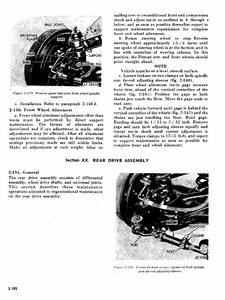


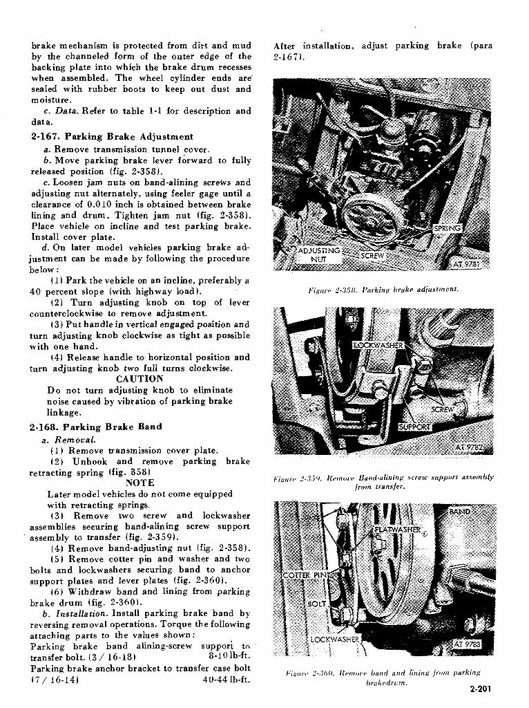


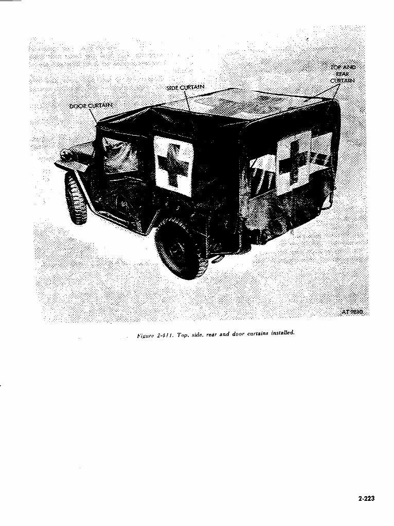


CHAPTER 3
MATERIEL USED IN CONJUNCTION WITH MAJOR ITEMS
Section I.
3-1. Scope
a. This chapter contains instructions for organizational maintenance of the eight special pupose kits issued for installation on the ‘/4 Ton, 4 x 4 Utility Truck Models, M151, MlSlAl, and MlSlA2 as well as description of the major units of each kit and their ‘function in relation to the components of the vehicle. Special pupose kits applicable to M 151, MlSlAl and MlSlA2 vehicles consist of Winterization kit (- 65’F ), Hardtop Kit, Door and Side Curtain Kit, M 14 / 16 Rifle Mount Kit, Machinegun Mounting Kit, Deepwater Fording Kit, Hot Water Heater (- 2SCF) Kit, and loo-ampere Alternator Kit. Only the latter two kits are applicable to the MlSlAlC and M825 vehicles, and only the latter three kits are applicable to the M718 and M718Al vehicles.
b. These kits are authorized for issue under criteria defined in SB 9-16 (winterization kits) and SB 9-155 (deepwater fording kit) and SB 11-131 (loo-ampere generator kit). The M14/ 16 rifle mount kit is authorized to meet local requirements for stowage and use of the rifle.
3-2. Maintenance Allocation
The prescribed maintenance responsibilities will
apply as shown in the vehicle maintenance
GENERAL
allocation chart (app. B). Any need for cleaning, lubrication, replacement, or repair detected in the equipment beyond the scope of this publication is to be immediately reported to the designated authority.
3-3. Service Upon Receipt of Materiel
a. General. (1) When a vehicle equipped with a new or
reconditioned kit is received determine that the kit has been properly prepared for service and that all necessary parts are present. Inspect all assemblies, subassemblies, and parts for proper assembly and condition. If any exterior surfaces are coated with rust-preventive compound, remove with dry- cleaning solvent or mineral spirits paint thinner.
(2) Ordinary deficiencies disclosed during preliminary inspection servicing or during in- stallation will be corrected by support maintenance personnel.
(3) Serious deficiencies detected in the equipment which occur under the circumstances indicated in TM 38-750 should be immediately reported in accordance with instructions in these regulations.
b. Specific Procedures. For specific procedures refer to the applicable section.
Section IT. WlNTERlZATlON KIT (-65 OF.)
3-4. Description and Data
a. General. The vehicle winterization kit (- 65OF) consists of a gasoline burning crew compartment heater of the fresh-air type equipped with a windshield defroster, battery compartment heater, manually controlled engine oil pan heater, and automatic controlsfor heating the vehicle when unattended. Also furnished in the kit is a standard slave receptacle installed on the right cowl, and a hood cover and an adjustable brush guard cover for regulating engine temperature under arctic con- ditions.
b. Gasoline Burning Heater. The gasoline burning heater supplied with this kit (fig. 3-l) receives its fuel from the vehicle fuel tank. An electric fuel pump is employed to supply
pressurized fuel to the heater. Fresh air is supplied to the heater inlet through an air intake hood (fig. 3-2) located at the rear top of the hardtop roof, and a duct assembly (fig. 3-3). Heated air from the heater is diverted for crew compartment heating and ducted through hoses to provide windshield defrosting. Automatic temperature control of air flow is provided for heating of the batter box. Heater exhaust gas can be diverted to a shroud enclosing part of the engine oil pan to heat the engine lubricating oil. Two heat intensity outputs are available and are controlled by a three position control switch. An emergency switch is provided to permit rapid shut down of the heater to prevent drawing of contaminated air into the vehicle in the event of an atomic or gas attack.
3-1
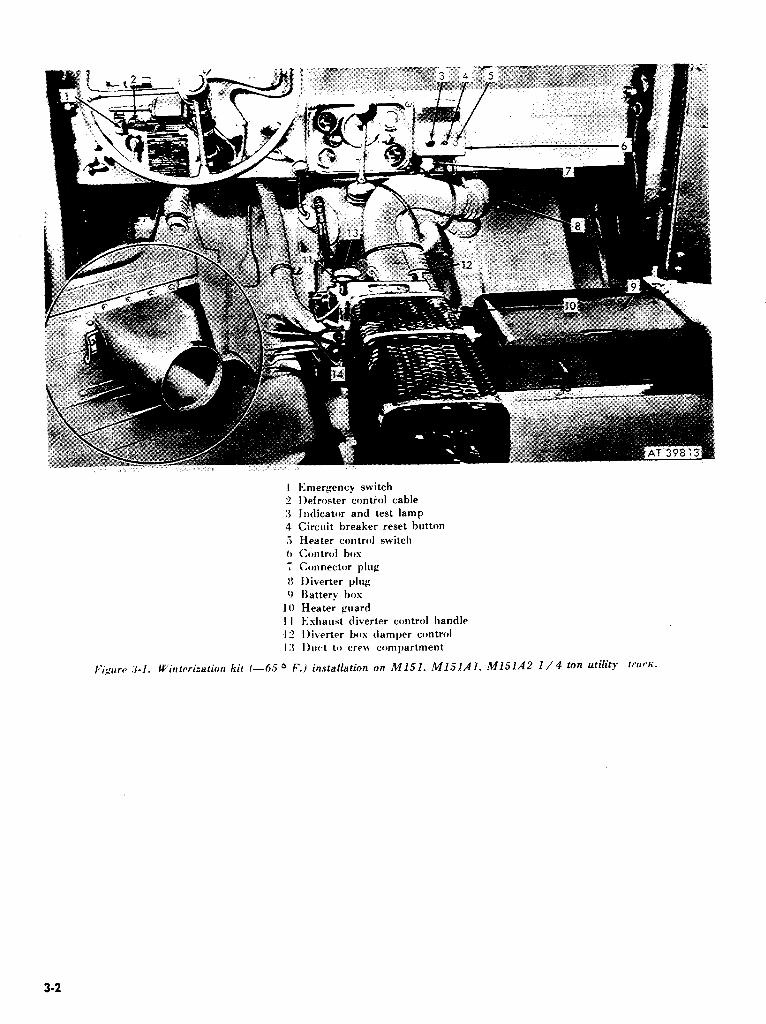
l+Imergency switch l)efroster contiol cable
Indicator and test lamp Circuit breaker reset button
Heater control switch
Control box
Connector plug
IIiverter plug
Batter?; bos
Heater guard Eshaust diverter control handle
Ijiverter box damper control
I)wt to cre\F compartment
/~i~rtrc~ .7-l. Wirrtcrization kit /-_(,.> -O F.) installation on M151. M151AI. MlSlA.2 l/4 ton utility trur’fi.
3-2

I:;#,,,,.,, .u. 1 /4 ton utility truck. MlSl. Ml5lAl. and M151A2 hardtop roof. hood assembly and KilSkf’l.

c. Electrical Controls. In order to prevent damage to the heat exchanger unit, a time delay mechanism is built into the on-off switch circuit. With this system, the blower continues to run after the switch has been turned off and fuel has ceased to flow to the burner. A temperature sensitive switch shuts off current to the blower only when the
%eat exchanger has cooled to the point that warpage of the heat exchanger or other damage cannot occur. The control switch panel also contains an overload relay with a reset feature to prevent damage to the electrical wiring in case of electrical malfunction. A warning light is incorporated into the control switch panel. This light serves a double purpose. First it indicates that the burner is in operation since it is connected to a temperature sensitive switch. Second, the light continues to burn after the heater is shut off and goes out only when the burner is cool enough to re-ignite safely. A second switch is also furnished, covered by a safety panel, which shuts off the whole heater electrical system disregarding damage to components. This emergency switch is for use only in an atomic or chemical warfare attack to prevent the heater from circulating contaminated air inside the vehicle.
d. Slave Receptacle. An electrical slave recep- tacle located on the right cowl provides a means of starting the vehicle with a service cable connected to a cold-starting aid kit (slave kit).
e. Hood and Brush Covers. A hood cover and brush guard cover protect the engine from cold weather. The cover on the radiator brush guard controls the flow of cold air through the radiator and protects the engine from windblown snow.
f. Refer to table l-l for tabulated data.
3-5. Service Upon Receipt of Materiel
NOTE Key numerals in parentheses refer to figure 3-1.
a. Snap the “emergency switch” (1) to “ON”’ position.
b. Press reset button (4) on control box. c. Use “press to test” feature on indicator lamp
(3). The lamp should light. d.Snap control switch (5) to “ON-HI” position.
The heater fuel pump should start immediately and the indicator light (3) should come on within two minutes after the control switch is snapped on.
e. The heater blower should transfer from low speed to high speed operation when the indicator light comes on.
f. Check operation of battery compartment damper actuator. With a temperature of ap- proximately lOOoF. in the battery compartment, the actuator should close the damper. When the temperature in the battery box drops to ap- proximately 70°F. the actuator should open the
damper permitting heated air to again flow to the batteries. Perform test by removing battery compartment and battery box covers after the damper door has closed. This will allow the thermostat to cool more rapidly causing the ac- tuator to open the damper. If the damper opens when it should close, reverse the thermostat lead wire connections at the terminal strip of the .ac- tuator (fig. 3-9). Repeat test.
g. Pull exhaust diverter control handle (11) up. Check for heat at the engine oil pan shroud.
h. Push exhaust diverter control handle down. Check for exhaust gas from heater exhaust pipe and for exhaust smoke. Heavy smoking indicates a malfunction in heater.
i. Position diverter box damper control (12) handle toward the exhaust diverter control handle (11). This positions the damper for maximum air to the defroster diverter.
j. Position defroster diverter control handle to “ON”. Check for hot air output from both.defroster nozzles.
k. Snap control switch to “ON-LOW” position. Check for lower temperature air leaving the heater. Blower speed should remain constant for both the “ON-HI” and “ON-LO” positions of the control switch since switch controls heat output, not blower speed.
1. Snap control switch to “OFF” position. The indicator light and the blower must operate for several minutes until the heater has cooled.
m. Check operation of emergency switch. (1) Remove the five-pin connector plug (7)
from the control box (6). (2) Press indicator light (3). Maintain finger
pressure on light, and snap emergency switch ( 1) to “OFF” position. The indicator light should go out. Snap emergency switch to “ON” position. The indzator light should come on. Release indicator light.
(3) Install five-pin connector plug to control box.
n. Check mechanical operation of circuit breaker.
( 1) Remove five-pin connecto? plug (7) from control box. (6).
(2) Press indicator light (3). Maintain finger pressure on light. Pull circuit breaker reset button (4) out to “open” position, using finger-nail pressure under lip of button. Indicator light should go out. Push reset button. Indicator light should come on. Release indicator light.
(3) Install five-pin connector plug to control box.
o-Replace any unit which fails to pass any test or shows signs of failure such as intermittent operation. Tighten hose clamps, electrical con-
3-4

nectars, mounting and attaching screws, and controls, as necessary, and fill fuel tank to minimize condensation.
3-6. Preventive Maintenance Services
B. Daily. During cold-weather operation, the heater fuel filter must be removed and drained of water daily, using the special tool wrench 10950836 which is provided as part of the kit. This helps to prevent the lines from freezing. TM 9- 2320-218-10 describes the daily preventive- maintenance service to be performed on the -65OF. winterization equipment by the driver each day the vehicle is in operation.
6. Weekly. ( 1) Inspect heater electrical components.
Repair or replace as necessary. (2) Inspect for loose defroster nozzles. Tighten
as necessary. 13) Perform all preventive-maintenance
services as directed in TM 9-8662. c. Lubrication. Lubrication of equipment in-
stalled with the winterization kit consists of “oil can points” which require sparing use of OE or OES (oil, engine). Every 1000 miles or semiannually lubricate all pivot points of starter detent on older model vehicles, bail pivot and cap threads of slave receptacle, pivot points of diverter actuator and defroster levers, and the exhaust diverter control cable sleeve. The heater blower motor does not require additional lubrication.
d. Seasonal. Perform all seasonal preventive maintenance as directed in TM 9-8662.
3-7. Troubleshooting.
NOTE For wiring diagram, refer to figure 3-4.
a. Heater Assembly. For troubleshooting in- structions on the heater assembly, refer to TM 9, 8662.
6. Battery Heat Damper Actuator Assembly. If the actuator fails to operate, perform the following test:
(1) Connect a jumper wire between the positive battery cable and the terminals of the actuator. Touch each terminal alternately while observing the damper. If the actuator operates normally, the thermostat or connecting wiring must be repaired or replaced.
(21 If the actuator fails to operate, check for improper grounding of the actuator, diverter, or adapter. To checks, connect a jumper wire between the battery negative cable clamp and a bare metal screw head on the actuator assembly. Alternately touch the terminals with the jumper wire as in ( 1)
above. (3 ) If the actuator operates normall_y with the
grounding jumper in use, remove the paint under the lead of one attaching screw of the actuator, diverter and adapter. Tighten screws.
(4) If the actuator fails to operate with jumper, replace the diverter actuator assembly (para 3-14).
c. Slave Receptacle. For troubleshooting in- structions on the slave receptacle refer to table 3-l.
3-8. Heater Assembly
a. Removal (Heater Assembly 8720193).
3s

r -_----_- I
1 I
REMOVE JUMPER
I THERMOSTAT IS
1 \
--------- ---_---____----_____~~~-~~~--~~ FUEL VALVE
7 I
WHEN USED
I
I THERMOSTAT
I CONNECTOR
I I CONTROL BOX I I
I
I 8’
MOTOR
& FUEL PUMP
CONNECTOR
u 4 t
TERMINAL STRIP r-1-y I
I m _“I I
i&J c -- -- 1 i2 4 16 !3 7
_- -- :
LFLAME DETECTOR SWITCH
tTIME DELAY SWITCH
r __-_-__-___-_-___---_-- CIRCUIT
BREPKER
HEATER CONTROL SWITCH / INDICATOR
m-l I
I I I
c CONNECTOR a------_-
I:i,qt:rrB .‘I-,/.. Wirinp diagram I-6S°F.) winterization kit.
ORD El0908
I I 1 I I I
I
I
-:
3-6
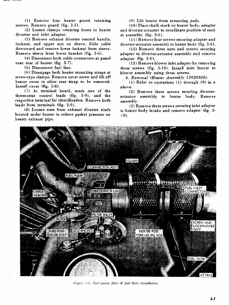
(I) Remove four heater guard retaining screws. Remove guard (fig. 3-5 1.
(2) Loosen clamps retaining hoses to heater diverter and inlet adapter.
(3) Remove exhaust diverter control handle, locknut, and upper nut on sleeve. Slide cable downward and remove lower locknut from sleeve. Remove sleeve from lower bracket (fig. 3-6).
(4) Disconnect both cable connectors at panel near rear of heater (fig. 3-7).
(5) Disconnect fuel line. (ii) Disengage both heater mounting straps at
screw-type clamps. Remove cover screw and lift off heater cover to allow rear strap to be removed. Install cover (fig. 3-8).
(7) At terminal board, mark one of the thermostat control leads (fig. 3-91, and the respective terminal for identification. Remove both leads from terminals (fig. 3-9).
(8) Loosen nuts from exhaust diverter studs located under heater to relieve gasket pressure on heater exhaust pipe.
(9) Lift heater from mounting pads. (10 1 Place chalk mark on heater body, adapter
and diverter-actuator to coordinate position of each at assembly (fig. 3-6).
(I I) Remove four screws securing adapter and diverter-actuator assembly to heater body (fig. 3-6).
(12) Remove three nuts and screws securing adapter to diverter-actuator assembly and remove adapter (fig. 3-6).
( 13 1 Remove blower inlet adapter by removing three screws (fig. 3-10). Install inlet louver to blower assembly using three screws.
b. Removal (Heater Assembly 10920608). (1) Refer to operations (I) through (9) in a
above. (2) Remove three screws securing diverter-
actuator assembly to heater body. Remove assembly .
(3) Remove three screws securing inlet adapter to heater body intake and remove adapter (fig. 3- 10).
3-7

I*i’purca 3-6. Exhuast divert& control handle removal.
/:ig,rcrrc 3-T. Heater wiring connections and mountings. I*‘i,crtrrc 3-H. Fuel lines and mounting straps.
3-8 _

k’ipurc* J-0. Fuel pump cable and connector.
c. Installation. Reverse procedures in a or b
above as applicable for heater assembly being in stalled.
NOTE Install ground cable under lockwasher at right front heater guard mounting screw.
3-9. Fuel Pump
a. Removal. Refer to figure 3-5. (1) Disconnect upper fuel line from fuel pump. (2) Disconnect both fuel lines from tee at
bottom of fuel pump. (3) Remove tee from fuel pump. (4) Disconnect cable connector at fuel pump
(fig. 3-91. (51 Remove mounting nuts, washers, and
screws. Remove pump. 6. Installation. Reverse procedure shown in (5)
through ( I), a above.
3-9

3-10. Fuel Filter
a. Removal. Refer to figure 3-5. (1) Disconnect both fuel lines from fuel filter
assembly. (2) Remove two mounting screws. (3) Remove elbow from fuel outlet.
b. Installation. Reverse procedure shown in (3) through (1) of a above.
3-11. Defroster Diverter Assembly
a. RemovaL Refer to figure 3-11. (1) Loosen three clamps retaining hoses to
diverter assembly and remove hoses.
(2) Remove two mounting screws, washers, and nuts.
b. Installation. Refer to figure 3-11. (I 1 Attach diverter assembly to lower lip of
dash panel with two screws, washers, and nuts. (2) Position clamp and connect hose from
heater to inlet at bottom of diverter. Tighten clamp screws.
(3 1 Connect Hose from left defroster nozzle to left top of diverter. Tighten clamp screw. Connect hose from right defroster nozzle to right top outlet of diverter. Tighten clamp screw.
3-12. Emergency Switch (1) Position switch to forward side of in- (fig. 3-12 1 strument panel with the word “ON” upward.
a. Removal. (2) Position guard to instrument panei and
(1) Disconnect both cable connectors from over switch toggle. Secure with two screw and lock-
switch. washer assemblies.
(2) Remove two screw and lockwasher (3 1 Connect
assemblies retaining heater guard to instrument lower connection
panel and switch. Remove guard and switch. (4) Connect b. Installation. upper connection
cable from control box to the of switch. cable from ignition switch to of switch.
3-10

3-13. Control Box Assembly
a. Removal. Refer to figure 3-13. (1) Disconnect cable plug at underside of
control box. (2) Disconnect emergency switch cable under
instrument panel. (3) Remove two mounting screw and lock-
washer assemblies retaining control box to mounting bracket.
b. Installation. (1) Position control box to mounting bracket.
Install two mounting screw and lockwasher assemblies.
(2) Connect emergency switch cable to switch. (3) Connect heater cable and connector to
control box. c. Repair.
(1) Remove two screws securing control box cover (fig. 3-13). Remove cover.
(2) Disconnect two jumpers and one cable from rear of switch.
(3) Remove locknut (fig. 3-13) securing switch to cover.
I~*i,~~rr* .7-12. Emcrgmc~ switch and instruction pfate.
3-11

(4) Install new switch by reversing procedure above.
NOTE Unscrew lens cover to replace lamp.
3-14. Diverter Actuator Assembly
a. Removal (Heater Assembly 870193) (fig. 3-
9). (1) Loosen both hose clamps and remove
defroster hose and battery box hose from diverter assembly.
(2) Remove exhaust diverter control handle (fig. 3-6).
( 3 ) Mark one battery box thermostat lead wire and its respective terminal. Disconnect both lead wires from actuator terminal strip.
(4) Remove four screws securing diverter adapter to heater body. Remove diverter and adapter.
(5) Remove three screws, washers, and nuts securing adapter to diverter.
b. Removal (Heater Assembly 10920608). Refer to figure 3-9.
3-12
(1) Perform (1) through (31 above. (21 Remove three diverter to heater body
attaching screws. Remove diverter-actuator assembly .
c. Installation. Reverse procedures in a and b above as applicable for heater being installed.
3-15. Slave Receptacle Assembly
a. RemovaLRefer tdfigures 3-14, 3-15 and 3-16. (1) Remove right front seat and battery
compartment cover. Remove battery winterization cover. Disconnect and remove outer battery.
(2) Remove nut from left battery positive terminal and disconnect slave cable.
(31 Remove retaining screw, washer, nut and cable clamps from body right side panel.
(4) Remove cable retaining clips from right cowl channel.
(5) Remove four receptacle-to-cowl retaining screws, lockwashers, flat washers, and nuts. Ground cable is attached by lower left screw.
(6) Remove receptacle assembly from cowl. b. Installation.

I*‘iprrrv 3-1.1. Slave cable installation body right side panel.
I*‘ig~~rc~ ~-15. Slave cable installation-cowl channel.

(11 Position receptacle to right cowl. (2) Insert one screw through lower left
mounting hole. (3) Install three screws, flat washers, lock-
washers, and nuts to remaining three holes. (4) Position lockwasher and receptacle ground
cable (short cable) over lower left mounting screw; install lockwasher and nut.
(5) Route receptacle long cable along battery cable and insert through grommet in seat riser.
(6) Position two cable retaining clips over battery and receptacle cables and attach clips to right cowl channel.
( 7 1 Position cable retaining clamp over battery and receptacle cables and install retaining screw, washer, and nut in body right side panel.
(8) Position receptacle cable end to battery positive terminal and install nut.
(9 1 Install and connect cables to right battery. Install battery compartment cover and right front seat.
3-16. Electrical Cable Assemblies
a. Removal. Before starting removal of any
electrical cable in the vehicle heater system, disconnect the connector to main wiring harness cable at the wiring harness. Remove any of the following cable assemblies by disconnecting connectors at both ends of the cable assembly heater to fuel pump, heater to control box, con- nector to ignition switch, and control box to emergency switch (fig. 3-6).
b. Installation.If cable was burned, troubleshoot the heater system before installing a new cable assembly. If cable was’damaged by other causes, install cable by connecting at both ends of ap- propriate cable assembly (fig. 3-7 1. ‘Connect heater syste’in to vehicle electrical system at conn&tor to main wiring harness.
3-17. Air Hose Replacement
Use defective air hose as a template and cut hose material to the required length. Install screw-driver type clamps to new hose, position hose to inlet and outlet, and tighten clamps securely.
Table .3-l. Troubleshooting-Slave Receptacle
Maffdwtion Probable cause Correctlbe action
No input when ‘service cable is connected to receptacle
a. Improper pdrity
h. Cable not properly grounded
v. Receptacle cable not connected properly to battery terminal
Check instruc;ions for use of cold starting kit (TM WOib Check receptacle ground cable for loose connection Check cable at battery for proper electrical connections
Section Ill. HARDTOP KIT
3-18. Description and Data
a. Description The hardtop kit is a metal and glass enclosure designed to protect vehicle and crew from weather extremes and provide comfort and vision for the crew. It is fabricated of aluminum panels and doors which are assembled and attached to the body with common fasteners bolts, nuts, and screws. Panels are of a convenient size so the whole unit may be shipped knocked-down without excessive cubage requirements. The doors are equipped with
‘weather-resistant strip and is sealed to the basic vehicle body. Refer to figure 3-16.
6. Data. Refer to table 1-l for tabulated data.
3-19. Service Upon Receipt of Materiel
a.Tnspect all bolts, nuts, and attaching parts for security of attachment and tightness.
b. Inspect glass for broken or chipped panes. Check sliding windows for ease of operation and weather sealing properties. Inspect all sealing
3.14
weatherstrips for air leaks. Inspect doors for ease’of operation, latching and weather sealing.
c. Inspect insulating materials for security of attachment.
d. Inspect interior and exterior body panels for scratches, dents, or abrasions which might affect corrosion resistance or protective qualities Of the
body.
3.20. Preventive Maintenance
a. DaiZy (TM 9-2320-218-10). Describes the preventive-maintenance services performed on the hardtop. kit by the driver each day the vehicle is operated.
b. Semiannually. (1) Inspect all bolts, nuts, and screws for
security of attachment and tightness. (2) Examine aluminum hardtop body panels
for signs of corrosion or fatigue at joints and at- taching holes. Clean corrosion from body panels and paint with zinc chromate primer followed by

finish coat. If welding of aluminum is required, notify support maintenance.
(3) Inspect glass for broken or chipped panes which will interfere with vision, comfort, or safety. If glass replacement is necessary notify support maintenance.
(41 Inspect condition of door hinges, lockes, weatherstrip, etc., for serviceability and worn parts. Refer to support maintenance for repair or replacement of parts.
air leaks at attachment points. If sealing material
(51 Inspect weather sealing material for hardening and loss of sealing properties. Inspect for
requires replacement, coordinate with support- maintenance.
(6) Inspect any insulating material for security of adhesion to body panels. If application of adhesive material is required, coordinate with support maintenance.
3-21. Troubleshooting
maintenance.
For troubleshooting refer to table 3-2.
3-22. Service Instructions
For major repairs to body or removal and in- stallation of hardtop kit, refer vehicle to support
MalfuAction . ..- .-.
I 1. Ih~w not latching 2. Excessive rattles
3. Sticking door glass
4. Excessive air leaks
.i. Water leaks
0. Cracked glass i
Table 3-2. Troubleshooting-Hardtop Kit
Prohabie cause
Broken or sticking lock a. Loose parts or joints 6. Worn or damaged glass channel
Worn or damaged glass channel a. Loose parts or joints /j. Worn or damaged glass channel
a. Loose parts or joints
6. Worn or damaged glass channels Worn or damaged glass channels
Corrective action
Refer to support maintenance
a. Tighten 6. Refer to support maintenance.
Refer to support maintenance
U. Tighten 6. Refer to support maintenance. a. Tighten I). Refer to support maintenance.
Refer to support maintenance
Section IV. HOT WATER HEATER KIT (-29’F.J
3-23. Description and Data
a. GeneraLThe hot water kit (- 25OF.) includes a crew compartment heater with defroster, a slave receptacle, and a brush guard cover. The kit is for use on vehicles operated in areas where the normal temperature during the coldest part of the year is above -25°F. Vehicles with a canvas passenger compartment enclosure may be equipped with this heater. Vehicles equipped with this kit may be used for deep water fording when the deep water fording kit is installed.
b. Hot Water Heater(fig. 3-17). As the hot water heater obtains heat from the engine coolant, the engine temperature must be in the normal range for maximum heater output. The heater is connected to the engine cooling system by suitable fittings and hoses and is mounted under the dash panel below
the right cowl ventilator. Outside air is drawn into the heater through the heater core by a heavy-duty squirrel cage-type blower. A voltage dropping resistor is used to provide two blower speeds. The air heated by the core is distributed to the vehicle interior and windshield glass through hoses and ducts. When outside air operation is not desired, air from within the vehicle is drawn through openings in the adapter under the cowl ventilator and recirculated through the heater core. Shut-off fittings at the water pump and cylinder head are provided to control the circulation of coolant throught the heater system and to permit removal of the heater without loss of coolant. Controls include a driver heater tube control for directing all heat to the driver and an auxiliary beat door for the passenger.
3-15

I.‘igur.c* 3-L 7. Mot water healer kit (-.?L~~T.I installed.
c. Slave Receptacle. A slave electrical receptacle (fig. 3-15) located on the right cowl provides a means of starting the vehicle with a service cable connected to a cold-starting aid kit (slave kit).
d. Brush Guard Cover and Flap. A cover on the radiator brush guard controls the flow of cold air through the radiator and protects the engine from windblown snow. A flap in the cover can be opened to admit air for engine cooling.
e. Data. Refer to table l-l for tabulated data.
3-24. Service Upon Receipt of Material
a.Operate all controls. Refer to TM 9-2320-2 18- 10 and figure 3-17.
b. Perform all daily and semiannual preventive maintenance. Refer to TM 9-2320-218-10 for daily preventive maintenance and paragraph 3-28 for preventive-maintenance instructions. Correct or report all deficiencies.
c.Lower windshield and inspect for damaged or misplaced windshield-to-body rubber seal. Inspect sealing surfaces and defroster air passages for obstruction, sand, or dirt.
3-25. Preventive Maintenance
a. Daily. TM 9-2320-218-10 describes the preventive-maintenance service performed on the - 25’F. heater equipment by the driver each day the vehicle is operated. No other daily service is required. - b. Semiannually.
(1) Inspect heater electrical components. Repair and/or replace as necessary.
3-16
(21 Inspect brush guard cover and flap for deterioration and tears. Repair or replace as necessary.
(3) Inspect for loose defroster nozzles. Tighten as necessary.
c. Lubrication. Lubrication of the hot water kit consists of “oil can points” which require sparing use of lubricating oil (OES). Every 1000 miles or semiannually, lubricate bail pivot and cap threads of, slave receptacle, pivot points of driver heat and defroster levers, and the auxiliary heat door hinge. The heater blower motor does not require lubrication.
3-26. Troubleshooting.
For troubleshooting the hot water heater (- 2SbF.1 refer to table 3-3.
3-27. Diverter Box.
a. Removal. Refer to figures 3-17 and 3-18. (1) Remove three diverter box-to-heater
retaining screws and lockwashers. (21 Remove diverter box from heater. (3) Remove right defroster hose elbow from
nozzle flange and diverter. (4) Disconnect duct from diverter.
b. Installation. Refer to figures 3-17 and 3-18. (11 Connect hot air duct to diverter opening
(driver side), and right defroster hose elbow to right . side opening and nozzle flange.
(2 I Position diverter box to heater outlet; insert three screws and lockwashers.
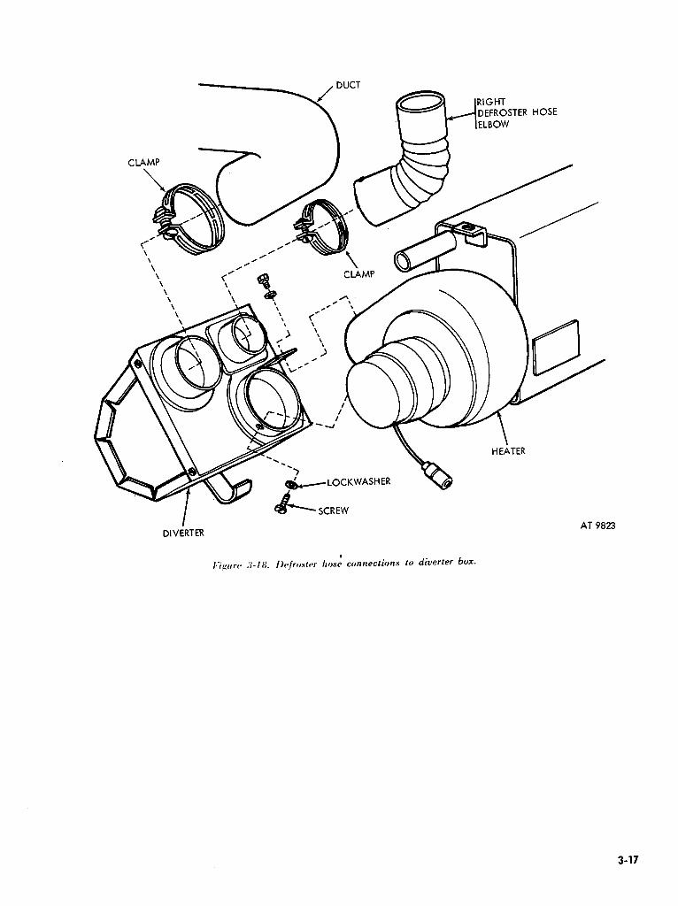
CLAMP
-\ \ \
DIVERTER AT 9823
3-17

Table 3-X Troubleshooting -259F. Hot Water Heater.
I. Cool or cold air at outlets after engine reached normal operating temperature.
2. Cool or cold air outlets due to low temperature.
3. No air flow at defroster
4. No air flow at driver heat outlet.
3. Hlower motor inoperative
0. Hlower motor operates on “HI” 0t1ly.
7. No input when service cable is connected to receptacle.
il.
6.
f’.
tl.
il.
I).
ii.
I).
f’.
rl.
4.
I). ii.
1).
(‘.
Il.
ii.
6.
V.
il.
6.
C.
One shut-off cock partially or fully closed.
Soft or collapsed hot water hoses. Air in heater
Plugged heater core
Defective engine thermostat. Extreme cold weather Hose disconnected at nozzle. Hose disconnected at diverter.
Collapsed hose
Leaking windshield to body seal.
Hose disconnected at box. Collapsed or cut hose Lead to heater switch netted. Heater electrical open
Ijrfective blower motor
Ijefective switch or
breaker. Loose lead to switch
circuit
Ijefective resistor Defective switch Cable not properly bmounded
diverter
discon-
circuit.
1niprol~er polarity
Receptacle cable not properly connected to battery terminal.
3-28. Heater Assembly
a. Removal. ( 1) Close both shut-off cocks by turning clock-
wise (fig. 3-191. (21 Remove four weldment screws and
washers. (31 Disconnect blower motor cable from
circuit breaker cable (fig. 3-20). (4) Disconnect two hoses from heater core. (5) Remove two toeboard-to-bracket-retaining
screws, flat washers, and weldment heater nuts. (6) Remove four top cowl-to-core heater
mounting retaining screws, washers, and lock- washers (fig. 3-2 11.
Corrective action
Check if shut-off cocks are open (rotate counter clockwise to open 1 Replaces hoses (para 3-301 Bleed heater lpara 3-28) Check for leaking cylinder head gasket if au recurs. Clean or replace heater core (para 3-281 Replace thermostat Install brush guard cover. Connect hose nozzle (para 3-321 Connect hose to diverter box lpara 3-321 Repair or replace hose (para 3-, 321 Notify support maintenance.
Connect hose to diverter box (para 3-321. Replace hose (para 3-321 Connect lead to heater switch (fig. 3-201 Check heater electrical circuit for improper or loose connections (para 3-3.51 Replace blower motor assembly (para 3-361 Replace as necessary (para 3-331
Check resistor leads to switch (fig. 3-20) Replace resistor (para 3-341 Repiacc switch (para 3-331 Check receptacle ground cable for loose connection to toeboard
(fig. 3-1.51 Check instructions for use of cold starting kit. Check cable : connection at battery for pr’oper connection.
b. Installation. (1) Position heater to intake duct under right
side of dash panel. (2) Install four screws, flat washers, and nuts
to holes in top cowl and to intake duct. (3) Install two screws, flat washers, and nuts
to holes in toeboard and heater weldment bracket. (4) Connect two heater hoses to heater core
tubes. Tighten clamp screws. (51 Connect blower motor cable to circuit
breaker cable. (6) Turn both shut-off cocks counter clockwise
to open position. Check engine coolant level. (7) Start engine and operate until normal
engine operating temperature is reached.
3-18

I~‘igurc~ d-1 0. Heater shut-off cocks and heater hoses.
/-‘;~rrrc* . ‘y_v(). wirinp assembly-hot water heater. _
3-19

(8)
I*‘ipcr rc .&PI. Heater mounting.
Check engine coolant level.
3-29. Slave Receptacle Assembly
Refer to paragraph 3-16. a. Removal.
(I) Remove heater (para 3-28). (2) Remove right front seat and battery
compartment cover. Disconnect and remove right battery.
(3) Remove nut from left battery positive terminal and disconnect cable.
(4) Remove retaining screw, washer, nut and cable clamp from right body side panel.
(5) Remove cable retaining clips from right cowl channel.
(6) Remove four receptacle to cowl retaining screws, lockwashers, flat washers, and nuts (ground cable is attached to lower left screw ).
(7) Remove receptacle assembly from cowl. b. Installation.
(I) Position receptacle to right COWL
(2) Insert screw through lower left mounting hole.
(3) Install three screws, flat washers, lock- washers, and nuts to remaining three holes.
(4) Position lockwasher and receptacle ground cable (short cable) over lower left mounting screw ;
install lockwasher and nut. (5) Route long receptacle cable along battery
cable and insert through grommet in seat riser. (6) Position two cable retaining clips over
battery and receptacle cables and attach clips to right cowl channel.
(7) Position cable retaining clamp over battery and receptacle cables and install retaining screw washer and nut in right body side panel.
(8) Position receptacle cable end to left battery positive terminal and install nut.
(9) Install and connect cables to right battery. Install battery compartment cover and right front seat.
(10) Install heater (para 3-28).
3-30. Hot Water Hose, .
a. Removal. Refer to figure 3-19. (1) Close both shut-off cocks by turning clock-
wise. (2) Remove diverter box (para. 3-27). (3) Remove hose retaining clamp screw,
washer, and nut from right fender apron and remove clamp from hoses.
(4) Remove hose support clamp from heater hose at bend around firewall.
(5) Loosen hose clamp screw and remove hose from shut-off cock.
(6) Loosen clamp screw and remove hose from heater core tube. Remove hose clamp from hose.
(7 1 Pull hose from engine compartment through grommet in right tunnel panel.
b. Installation. (1) Cut replacement hose to proper length
(para. 3-26). (2) Route hose from engine compartment
through grommet in tunnel right panel. (3) Place clamp on end of hose and attach to
heater core tube. Tighten clamp screw. (4) Route hose to shut off cock. Place clamp
on hose and attach to shut off cock. Tighten clamp screw.
(5) Place retaining clamp over hoses and position to hole in fender apron. Secure clamp with screw, lockwasher, and nut.
(6) Install hose support clamp over heater hoses at bend around firewall.
(7) Turn shut-off cogk counterclockwise to open position. Check engine coolant level.
(8) Start engine and operate until engine reaches normal operating temperature.
(9) Check coolant level and add coolant as required.
3-31. Shut-Off Cocks
a. Removal. Refer to figure 3-19. (1) Drain coolant. (2) Disconnect hot water hose at shut-off cock. (3) Remove shut-off cock from adapter.
b. Installation (I 1 Install shut-off cock to adapter, (2 1 Connect hot water hose to shut-off cock. (3 1 Fill radiator with coolant. (4) Start engine and operate until engine
reaches normal operating temperature.
3-20

3-32. Defroster and Diverter Heater Hose a. Removal. Refer to figure 3-18.
(1) Remove four instrument cluster panel retaining screws and lockwashers.
(2 1 Disconnect speedometer and lay in- strument cluster panel aside with gage wires connected.
(3) Loosen clamp screw and remove hose from nozzle or adapter.
(4) Remove hose from diverter box. (5) Remove clamps from hose.
b. Installation.
NOTE Route left defroster (long) hose on top of speedometer cable and choke and throttle control cables. Position left defroster hose to diverter which is near the heater switch and steering column. Diverter which gives h&at to driver and heat to nozzle flange is positioned six inches from toeboard. (1) Cut new hose (para. 3-26) to proper
length. (2) Place clamp on end of hose and attach to
nozzle or adapter. ( 3 1 Place clamp over diverter end of hose and
connect hose to diverter box. (4) Connect speedometer cable to
speedometer. Connect defroster hose bracket to speedometer.
(5) Position instrument cluster panel to dash panel and install four retaining screws and lock- washers.
3-33. Heater Switch
a. Removal. Refer to figure 3-17. (11 Remove nut, lockwasher, nameplate, and
special washer from heater switch. (2) Remove switch from dash panel. (3) Remove cables connected to switch.
b. Installation. (1) Connect eyelet of cable (from top terminal
on circuit breaker) to center post on switch. (2) Connect eyelet of cable (from blower
motor) and lead from resistor to terminal on keyway side of switch.
(3 1 Connect remaining lead from resistor to remaining terminal on switch.
(4) Remove nut, lockwasher, and indexing washer from replacement switch.
(5) From behind dash Danel. insert switch through hole in dash panel. * ’
(6) Position nameplate to switch and install lockwasher and nut.
3-34. Resistor
a. Removal. (1) Remove heater switch. Refer to paragraph
3-33. (2) Remove two resistor retaining screws,
lockwashers and nuts from left body side panel. (3 I Remove resistor from left body side panel. (4) Disconnect two resistor leads from switch
terminals. b. Installation.
(1) Position resistor to holes in left body side panel.
(2) Install two screws, lockwashers, and nuts. (3) Route resistor leads along lip of dash panel
to heater switch location. (4) Connect resistor lead and lead from blower
motor to the terminal on keyway side of switch. (5) Connect remaining lead from resistor to
open terminal on switch.
(6) Install switch.
3-35. Circuit Breaker
a. Removal. Refer to figure 3-20. (1) Remove two circuit breaker retaining
screw, lockwashers, and nuts on left body side panel.
(2) Disconnect cables from circuit breakers. b. Installation.
(1) Position circuit breaker behind left body side panel and install two screws, lockwashers, and nuts.
(2) Cmnect cable from ignition switch to lower terminal on circuit breaker.
(3) Connect cable from heater switch to top terminal on circuit breaker.
3-36. Blower Motor and Wheel Assembly
a. Removal. Refer to figures 3-20 and 3-22. Disconnect blower motor to circuit breaker leads. Remove four screws and lockwashers attaching the blower motor and wheel to flange.
b. Installation.Position blower motor and wheel assembly to blower motor flange and install four lockwashers and screws. Connect blower motor cable to circuit breaker cable.
3-21

I:igurr~ J-22. [Icater assembly-major components-exploded view.
Section V. DEEPWATER FORDING KIT
3-37. Description and Data
a. Description The deepwater fording kit (fig. 3-231 consists of a carburetor air intake tube extension wh&h attaches to the air cleaner and is mounted at the body left side panel. An exhaust extension tube attaches to the exhaust flanged tailpipe and is secured with a support assembly at the body left rear panels. A fording valve control (fig. 3-241 mounted on the dash panel is connected to the fording valve by means of a flexible cable. A fording valve is mounted on the intake manifold which connects various vent lines to the intake manifold. A vent tube and fitting for venting the brake master cylinder is also included. Various brackets and standard bolts and nuts necessary to install the kit to the vehicle are also included. With this kit in- stalled, the vehicle can ford hardbottom water crossings up to 5 feet in depth.
NOTE Deepwater fording kit sealer MIL-S-12158
type 2, quantity one quart is provided with the kit for application to battery starter, and starter switch terminals to reduce the effects of corrosion.
b. Data. Refer to table l-l for tabulated data.
3-38. Service Upon Receipt Of Materiel
a. Inspect air intake tube for secure attachment to body and tight connection to air cleaner.
b. Inspect exhaust extension tailpipe for secure attachment to body and exhaust extension cover for operation. Inspect exhaust tailpipe extension for watertight connections.
c. Inspect installation of brake master cylinder vent for secure attachment.
d-Check tightness of vent connections located on firewall.
e. Operate engine and fording valve to verify operation.
f. Inspect fuel tank cap fording valve setting for ease of operation.
3-22

I*i’~*urr .3-2.Y. Deepwater fording kit installation.
3-23

Iq‘i,Lxlrc .?-24. Fordinp valve and cable.
3-39. Preventive Maintenance
a. Daily. TM 9-2320-218-10 to describe the preventive-maintenance services to be performed on the deepwater fording equipment by the driver each day the vehicle is operated.
b. Semiannually. ( 1) Inspect air intake tube for tight connection
to air cleaner inlet. (2) Inspect all exhaust extension tailpipe joints
for tight connections. Tighten connections or replace gaskets as necessary.
(3) Tighten all intake tubes and tailpipe ex- tension attaching brackets.
(4) Inspect all attaching brackets for bent, cracked, or broken parts. Replace as necessary.
(5) Tighten all vent line connections as necessary to prevent entrance of water.
(6) Verify operation of fording valve, controls, and linkage. Lubricate as necessary (TM 9-2320- 218-10). 3-40. Troubleshooting
For troubleshooting the vehicle with fording kit installed, refer to table 3-4.
3-41. Fording Valve
a. Removal. Refer to figure 3-24. ( 1) Disconnect control cable at valve operating
lever by loosening retaining screw in support bracket and pulling the eyed end of the control cable off valve operating lever.
(2 1 Remove valve cover vent tube from ventilator valve.
(3) Unscrew ventilator valve from fording valve body.
(4) Remove carburetor vent line. (5) Unscrew fording valve ‘from intake
manifold.
b. Installation. Reverse the order of (5) through (1) above.
NOTE Be sure the fording valve control is pushed completely in and that the control cable is properly positioned in the bracket before tightening retaining screw.
3-42. Four Way Ventilation Fitting.
a. Removal. Disconnect brake master cylinder, fuel tank, and windshield wiper tube fittings from four-way fitting on face of firewall. Remove fitting.
b. Installation. ( 1) Position fitting to fuel tank ventilation line
at grommet in firewall and install line to fitting finger tight.
(2) Position and install remaining three ventilation lines to the four way fitting.
(3) Check position of fitting and tighten all connections securely.
3-43. Fording Valve Control
a. Removal. ( 1) Remove control cable from control valve. (2) Remove nut retaining control assembly to
instrument panel and carefully pull control and cable from instrument panel and firewall along with instruction plate.
b. Installation. (1) Position instruction plate to instrument
panel and start eyed end of control cable through center hole.
(2) Place retaining nut and washer on cable and retain in position at instrument panel while pushing control and cable through instrument panel.
(3) Guide eyed end of cable through grommet in firewall.
(4) Grasp cable and pull until control is seated against instrument panel.
(5) Install control retaining nut and washer to instrument panel, being sure that instruction plate is properly seated against instrument panel.
(6) Connect eyed end of control cable to fording valve.
3-44. Intake Hose
a. Removal. (1) Remove two clamps retaining the flexible
intake tube to the air cleaner and extension intake tube.
(2 1 Compress flexible hose endwise and remove hose with clamps.
b. InstallatYon. (1) Position clamps at center of flexible hose. (2) Compress flexible hose endwise and install
hose on air cleaner and extension intake tube, making sure tube is curving freely and equally spaced on attaching ends.
3-24

3-45. Exhaust Extension Tailpipe Gasket
a. Removal. (1) Remove two screws and locknuts retaining
extension tailpipe to vehicle tailpipe. (2) Spread pipe flanges apart and remove
gasket.
b. Installation. (1) Clean vehicle tailpipe and extension
tailpipe mating flanges and position gasket between the flanges.
t 2) Install two screws and two hug locknuts and tighten to 12-I 5 lb-ft.
(3) Inspect joint for watertight connection.
Table 3-4. Troubleshooting Vehicle With Deepwater Fording Kit
Malfunction
1.
2.
Excessive smoking from vehicle exhaust extension
Loss of power
3. Stalling on land
4. Stalling in water
.i. Water in engine
0. Water in fuel
Probable causes ‘Corrective action
a.
h.
a. 1).
(‘.
d.
il .
h.
(‘.
(1
I’.
a.
0.
f’.
(1.
C.
il.
0.
r.
a.
b.
Carburetor air inlet restricted. Improper fording valve operation
Carburetor air inlet restricted Restricted exhaust extension
Improper fording valve operation
Fuel tank filler cap valve un- satisfactory. Carburetor not adjusted correctly. Carburetor air inlet restricted Restricted exhaust extension
Improper fording valve operation.
Fuel tank filler cap valve im- properly set. Leaks in air intake system
Leaking exhaust system
Improper fording valve operation
Loose ventilating line con- nections.
Fuel tank filler cap valve im- properly set Leaks in air intake system
Loose ventilating line con- nections
Improper fording valve operation
Fuel tank filler cap valve im- properly set
Improper fording valve IJperation.
c. Loose ventilating line con- nections.
tl. Leaks in air intake system
i:
a.
6.
(‘.
d.
il.
b.
(‘.
(I.
C.
a.
6.
(‘.
(1.
(‘.
a.
11.
(‘.
it .
6.
(‘.
(I.
Remove inlet pipe & clean. Disconnect vent inlet lines & verify valve operation tpara 3- 411. Remove inlet pipe & clean. Remove exhuast extension pipe & clean. Disconnect vent inlet lines and verify valve operation (para 3- 41). Replace cap.
Adjust carburetor.
Remove air inlet pipe and clean Remove exhaust pipe extension & clean. Disconnect vent inlet lines & verify valve operation lpara 3- 411. Position valve correctly or replace cap. Examine & tighten all air intake connections Examine d tighten all exhaust connections Disconnect vent inlet lines & verify valve operation lpara 3- 411. Examine & tighten ventilating line connections. Position valve correctly or replace cap. Examine & tighten all air intake connections. Change oil and oil filter. Examine all ventilating line connections and tighten as necessary. Change oil and oil filter. Disconnect vent inlet lines & verify valve operation (para 3- 41). Change oil 81 oil filter. Position valve correctly or replace cap. Drain water from fuel tank. I)isconnect vent inlet lines and verify valve operation (para 3- 4.1 t. Drain water from fuel tank. Kxamine all ventilating line connections & tighten as necessary. Drain water from fuel tank. Esamine & tighten leaking in- take connections. Drain water from fuel tank.
3-25

T&kc 3-4. Troublshooting Vehicle WithDeepwater Fording Kit-Continued
i. Water in brake fluid
Probable cause
a. Loose ventilating line con- nections.
h. improper fording valve operation
I’. Leaks in air intake system.
Correctwe act;on
Examine all ventilating line connections as necessary. Drain all contaminated brake fluid from system. Flush system & replenish fluid. Bleed brake systems. Disconnect vent inlet lines &
verify valve operation (para 3- 411. Drain all contaminated brake fluid from system. Flush system and replenish fluid. Bleed brake system.
Examine & tighten leaking air intake connections. Drain all
contaminated brake fluid from system. Flush system & replenish
fluid. Bleed brake system.
Section VI. loo-AMPERE ALTERNATOR KIT
3-46. Description and Data
a. General. The loo-ampere charging system (fig. 3-251 is used when the electrical requirements of special equipment such as radio transmitters exceed the capabilities of the standard 25.ampere charging system. The system consists of two major components; and alternating current generator which is in the same location as the standard generator; and a regulator which is located in the engine compartment on the right fender. The basic difference between this system and the standard system is that the generator unit produces alter- nating current rather than direct current. Since alternating current cannot be used to charge storage batteries or supply current directly to the vehicle electrical system, an internal rectifier is incorporated in the generator to convert the alternating current to direct current. All com- ponents of the system are waterproofed or sealed so vehicles with this equipment may be used for fording.
b. Alternator-The 100 ampere alternator (fig. 3- 251 is driven by four belts. Externally it is not
sealed ; however, the internal components are waterproof and cannot be damaged by submersion in water. The alternator will not function when submerged, but will start charging when removed from the water. The unit is cooled by a fan which is located at the rear of the generator housing.
c. Regulator.The solid state regulator (fig. 3-251 is a hermetically sealed unit and is not affected by water. It contains a load relay which connects the generating system to the vehicle batteries when the ignition switch is turned on. The load relay also connects the generator fields to the batteries for initial excitation. The regulator contains a carbon pile type voltage limiter which controls the generator field current and thus limits the system voltage. The voltage limiter is adjusted externally by a variable resistor located in the base of the regulator.
d. Data. Refer to table l-l for tabulated data.
3-47. Service Upon Receipt Of Materiel
Perform the preventive-maintenance services as specified in paragraph 3-48. Also, perform the voltage output test specified in paragraph 3-49 b.
3-26

POSITIVE (+) LEAD
MAIN LIGHTING CABLE CONNECTOR
IGNITION SWITCH CONNECTOR UKUMMt I AT 39843
3-48. Preventive Maintenance
a.Check fan and generator belt tension. All belts should have approximately l/2 inch deflection (par. 3-51).
b. Check generator and regulator, mounting screw, bolts, and nuts for tightness.
&Check to see that all cable connectors are tight. Check for breaks in conduits and harnesses.
d. Check battery cables for tightness and con- dition. Tighten, clean, or replace as required.
e. Turn ignition on; battery-generator indicator should move to the yellow band. Start engine. Allow engine to reach operating temperature and observe battery generator indicator. At ap- proximately 1,500 rpm, indicator should stay in the green band. Turn ignition off if indicator is not in the red band, troubleshoot the entire generating system.
3-49. Troubleshooting
a. GeneraLRefer to the following procedures and table 3-5.
b. Voltage Output Test. (I ) Connect a dc voltmeter, having a SO-volt
range, across the positive terminal of one battery and negative terminal of the other battery.
NOTE If vehicle is equipped with a slave receptacle, check voltage at the receptacle.
Turn ignition switch “ON”. Battery-generator indicator should move to the yellow band, and the voltmeter should read between 23 to 25 volts. Depress starter switch with ignition switch “ON”.
Observe voltmeter. If voltmeter indicates less than 18 volts vehicle cranking starter, discontinue at- tempting to start vehicle and replace both batteries. Disconnect voltmeter.
(2) When engine has started, allow engine to reach operating temperature. Connect voltmeter across batteries (1) above, between 27.5 to 28 volts, and battery-generator indicator should be in the green band. Turn on lights and any load not ex- ceeding 100 amperes. Voltage should be constant and remain 27.5 to 28 volts. If voltage drops below 27.5 volts, or exceeds 28 volts during the test, adjust the regulator voltage ( c below).
NOTE It is normal for the ac generator unit to whine or howl while charging (para. 3-51 b (8).
c. Regulator Voltage Adjustment (figs. 3-26 through 3-29). Remove plug from top or side of regulator. Using a screwdriver, turn the voltage adjusting rheostat in clockwise direction to increase voltage and in the counterclockwise direction to decrease voltage. Rheostat should not allow more than a 5-volt range in its adjustment and voltage is to remain stable. Apply sealing compound to threads of plug.
d. Visual Checks. Check security of all con- nectors and determine that the wiring is not dam aged.
e. Battery to Regulator Harness Check. Disconnect the battery wiring from the regulator (connector no. 1, fig. 3-26 1 and check the sockets then remove harness as follows:
3-27

( 1) Plus lead of voltmeter to socket A, negative lead to ground; voltmeter should indicate battery voltage.
(2 1 Plus lead of voltmeter to socket A, negative lead to socket B ; voltmeter should indicate battery voltage.
(3 1 Plus lead of voltmeter to socket F, negative lead to socket C (ignition switch “ON”), voltmeter should indicate battery voltage. If battery voltage is indicated in each test, connect harness connector to regulator. If battery voltage is not indicated, in- spected for damaged connectors, sockets, and wiring. Repair or replace harness as required.
f. Generator (Alternator) to Regulator Lead and Conduit Check. Disconnect the generator to
regulator lead and conduit at the generator (connector 3, fig. 3-261 and perform the following checks at the disconnected connector of the lead and conduit.
(1) Place positive lead of voltmeter to socket D and negative lead to socket E with ignition switch on. Voltmeter should indicate battery voltage.
(21 Connect negative lead of voltmeter to ground, and with positive lead contact in, turn sockets A, B, and C with ignition switch on. No voltage should be indicated on the voltmeter. If voltage readings are specified in d and e above and visual checks do not locate the trouble, perform the generator tests which follow:
g. Generator (Alternator) Tests. Proceed as follows :
CAUTION Perform the following checks with all electrical power on the vehicle off (ignition switch off) to prevent damage to the ohm:. meter.
Disconnect the conduit connector from the generator if not already disconnected. Set ohm- meter to low ohm scale (R x 1) and make the following checks at the-generator and generator receptacle.
(1) Check three-phase winding continuity. Connect ohmmeter leads to pins A and B, then to pins A and C, and finally to pins C and B. Ohm- meter should indicate no resistance (closed circuit).
(2) Check field resistance. Set ohmmeter selector to R x 1 scale. Connect ohmmeter leads to pins d and e of generator receptacle. Meter should read less than 4 ohms. To assure that brushes are contacting the field rings, and rings are clean throughout all points of contact, remove the fan and alternator belts from the alternator and rotate the rotor at least five times by hand. Ohmmeter reading should be constant and remain at ap- proximately 4 ohms or less. Install belts and adjust (para 3-52 1.
(31 Check for ground. With ohmmeter set on the ohms scale (R x 1001 check for pins A, B, and C to the alternator housing or case (ground). Ohm- meter should read infinite resistance (open circuit).
(41 Test alternator to regulator lead and conduit. Connect conduit connector at alternator receptacle and disconnect the same conduit at the regulator. Repeat the tests made on the alternator receptacle on the pins of the connector of the disconnected conduit (1) through (3) above. Results of tests should be the same; if not, conduit is defective. Repair or replace conduit as required (para 3-55) if the above tests do not locate the trouble continue to the next test.
3-28

GENERATOR IALTERNATOR)
NOTE:
C I -.D
c
-6 2 -0 ’ E -
I REGULATOR
TO MAIN LIGHTING CABLE ASSY. NO. 27
I
NO. 3
NC 56E
TO IGN. NO. 27A SWITCH
CIRCLE NUMBERS INDICATE TEST POINTS. RECEPTACLES ARE NOT NUMBERED.
NI
GRD
+ m GRD
- +
BATTERIES
2
AT 3992 1
I.i’g:rr rl’ 3-_‘h. 100 .4mjwrr generating system wiring connections.
3-29

----_--- --------- -------
l ALTERNATOR RECTIFIER. r
BATTERY (+)
VEHICLE ACCESSORIES
FOR PARALLELING
-_.__._..
1 BATTERY (-,
I I _---__----______----__-- -----a
RECTIFIED A.C. GENERATING SYSTEM SCHEMATIC WIRING DIAGRAM AT 39931
I~‘ig:rtrrr~ J-2 7. Schrmatic wiring diagram.
Table J-5. Troubleshooting-100 Ampere
1. No output
2. Low output: less than 27.5 volts.
3. High output: more than 28.5 volts.
f
Generating System
Broken or loose belts.
Generator seized. Broken wire.
1)isconnected wire.
Defective regulator. One or both batteries dead. Loose belts. Loose connection. Regulator out of adjustment.
One phase shorted on generator. One or both batteries dead.
One or both batteries low.
Regulator out of adjustment.
Wire shorted.
f
Corrective action
ii.
0.
(‘.
Il.
t-.
J il.
I,.
(‘.
(1. P.
il .
I).
V.
Adjust or replace belts lpara 3- 521. Replace generator t para 3-j 1). Replace or repair as required (fig. 3-261. Tighten all wires and connections (fig. 3-20 I. Replace regulator (para 3-50). Replace both batteries. Adjust belts (para 3-.521. Tighten connectors. Adjust voltage rheostat (para 3- 4Qc 1 or replace regulator (para :I-.50 1. Replace generator t para 3-50 i. Keplace both baiteries.
CAUTION Reversing polarity of battery will damage generator.
Replace both batteries.
Adjust voltage rheostat [para 3- 4’kI or replace regulator (para 3- 501. Check wiring (fig. 3-26).
3-30

Table 3-S. Troubleshooting-l 00 Ampere-Continued
. 4. Battery generator indicator stays
in red or yellow band with engine at 1500 rpm.
5. Belt squeal.
0. Battery uses too much water.
i. Battery does not hold charge.
Probable cause
ii.
I,.
(‘.
(1. P.
0.
b.
(‘.
rl.
P.
a.
0. i1.
b. C.
d.
Faulty indica&.
Broken connection. No output of generating system. One or both batteries dead.
Low voltage setting.
Glazed belts. One or more worn or broken belts. Generator seized. Loose belts. Seized water pump. High voltage setting.
Cracked battery case. Voltage limiter incorrectly ad- justed.
One or both batteries dead. Failed charging system.
Slipping belts.
3-50. Regulator Assembly
a. Removal. Refer to figure 3-28. (1) Disconnect vehicle ground cable terminal
at battery. (2 1 Disconnect the generator-to-regulator
conduit and the wiring harness from the regulator. (31 Remove four screws (10) and washers (4)
securing regulator assembly (2) to fender mounting brackets (3) and remove regulator assembly.
(4)Remove four screws (8) and washers (9) securing two brackets (1) to regulator.
b. Installation. (1) Secure regulator assembly to two brackets
(11 with four screws (8) and four internal teeth lockwashers (9 1.
(2) Install regulator assembly on fender brackets (3) using four screws (101 and washers (4).
(3) Connect generator-to-regulator conduit an.d the wiring harness to regulator.
(41 Tighten connectors to receptacles using a spanner wrench.
(5 1 Connect negative terminal (ground) to the battery.
Corrective action
21.
b. r.
Il.
P.
a. 0.
(‘.
d.
r.
il.
IL il.
0.
C.
(1.
Connect voltkfeter with 50 volt dc scale across vehicle battery. Check voltage. if between X.5 and 28. replace indicator. Check wiring (fig. 3-26). See items 1 and 2 above. Replace both batteries. Adjust voltage rheostat (para 3- 4%). Install new belt set (para 3-521. Install new belt set (para 3-52).
Replace generator (para 3-Sil. Adjust belt tension (para 3-52). Replace pump. Adjust voltage rheostat (para 3- 4%). Replace battery. Adjust voltage rheostat (para 3- 40~ I or replace regulator (para 3-501. Replace both batteries. Perform tests and adjustments (para 3-40). Refer to item .i above.
(6 1 Perform voltage output tests and regulator adjustment if required (para 3-52).
3-51. Generator Alternator Assembly
a. Removal. Refer to figure 3-29. (1) Remove air cleaner and carburetor air
intake hose. (2) Disconnect alternator to regulator conduit
at the generator receptacle using a spanner wrench. (3) Loosen alternator to alternator support
attaching bolts. Loosen adjusting arm capscrew at engine block. Remove alternator adjusting arm capscrew, washer and nut from alternator. Push alternator toward engine block and remove belts from alternator drive pulley.
(4) Remove alternator to support attaching bolts, washers and nuts aqd lift out alternator assembly.
(5) Remove washer and nut retaining alter- nator drive pulley to shaft.
(6) Remove pulley from shaft using a suitable puller. Remove Woodruff key from slot in shaft.
3-31
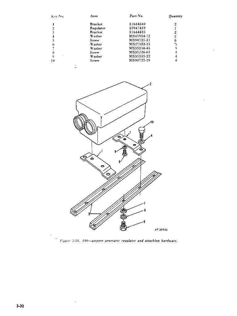
Item Part No. Quantity
1 Bracket 11644840 2 :! Regulator 1094i439 1 :% Bracket 11644835 2 4 Washer MS45904-72 5 .5 Screw MS90725-31 6 6 Washer MS2i183-13 3 -i Washer MS35338-45 5 8 Screw MS35226-63 4 0 Washer MS3533532 4
10 Screw MS90725-29 4
AT 399
/.‘i,g!r,rv 3-_‘I!. IOO-arnpcrc generator regulator and attachinp hardware.
3-32

I:i,~~rr* 3-20. 100 Arnperc generator-installed.
b. Installation. (1) Assemble pulley, to alternator shaft WA
one key, flat washer and nut. Tighten nut to 75-8 lb-ft torque.
(2) Position alternator on alternator support. (3) Secure alternator to support using two
bolts, four flat washers, and two safety nuts. Use one flat washer at each bolt head and another at each nut. Both bolts are to be installed with heads closest to the front of the vehicle. Tighten nuts snugly. Final tightening is to be performed after belt tension adjust (5 1 below.
NOTE Torque alternator mounting bracket bolts 58-65 lb-ft. Loose bolts may cause damage to cylinder block. (4) Attach adjusting arm to alternator cap-
screw, knurled washer and nut. Final tighten arm attaching screw and bolt at engine block after belt tension adjustment (5 1 below.
(5) Place fan and alternator belts in pulley grooves. Pull alternator outward and tighten ad- justing arm at point where some play remains in belts. Check adjustment by placing a straight edge over belt at the water pump pulley to the alternator pulley. A result of a firm push on a belt, a deflection of ‘/ inch from the straightedge should
be maintained on each belt. Adjust as required. If the four belts differ in tension, replace set. Tighten bolt securing alternator to support to 60-70 lb-ft. Tighten adjusting arm to engine block bolt to 47-56 lb-ft. Tighten adjusting arm to alternator screw to 35-40 lb-ft torque.
(6) As a preliminary test start engine without connecting the alternator to regulator conduit to the alternator. No noise should be produced by the alternator at any speed. If alternator is noisy during this test, remove alternator and inspect for cause of noise. If noise c3nnot be corrected without disassembly, obtain another alternator. If alter- nator is not noisy, stop engine and connect alter- nator to regulator conduit receptacle. Tighten cable connector securely using a spanner wrench.
(7) Install air cleaner and carburetor air intake hose.
(8 1 Perform voltage output tests and regulator adjustment if required (para 3-49 b).
NOTE With an electrical load on the charging system it is normal for the alternator unit to whine. If at any time mechanical binding or interference is suspected because of excessive noise perform the test in (5) above.
3-33

-3752 Fan and Alternator Belt Set
a. Removal. ( 1) Remove air cleaner and carburetor air
intake hose. (2 1 Loosen alternator to alternator support
attaching bolts. Loosen adjusting arm capscrew at engine block. Loosen alternator adjusting arm capscrew. Push alternator toward engine block and remove fan and alternator belts from alternator drive pulley. Remove each belt from the water pump pulley and work each belt out of the crankshaft pulley.
NOTE Belts are supplied in matched sets and should be replaced in sets.
b. Installation. (1) Install each belt onto the crankshaft
pulley and onto the water pump and generator pulleys. Adjust belt tension as prescribed in paragraph 3-5 1.
(2) Install air cleaner and carburetor air intake hose.
(3 ) Check operation of alternator as indicated by the battery-alternator indicator. If not satisfactory perform voltage output test and ad- justment as required (para 3-49 b 1.
3-53 Water Pump Pulley
a. Removal. (1) Remove brush guard, radiator, and
radiator fan shroud. (2) Release tension from fan and generator
belts (para 3-51) and remove belts from water pump pulley.
(31 Remove four screw and washer assemblies securing fan and water pump pulley to water pump (fig. 3-30). Lift off fan and pulley from water
pump. b. Installation.
(1) Install water pump pulley and fan to water
pump using four screw and washer assemblies. Tighten screws to 15-18 lb.-ft. torque.
(2) Install the three belts to the water pump pulley and alternator pulley and adjust belt tension (para 3-511.
(3) Install radiator, fan shroud, and brush guard.
(41 Fill cooling system (TM 9-2320-218-10). (5 ) Check operation of alternator as indicated
by the battery-charge indicator. If not satisfactory, perform voltage output test and adjustment as required (para 3-49bl.
3-54 Alternator Pulley
a. Removal. Refer to paragraph 3-51 a (1) through (6 1.
b. Installation. Refer to paragraph 3-5 1 b (1) through (81.
3-55 Alternator to Regulator Cable
a. Removal. Refer to figure 3-31. (1) Disconnect battery ground cable.
Disconnect cable connectors from alternator and regulator.
(2) Remove strap securing wiring harness to alternator to regulator cable.
(31 Remove four screws, nuts, and lock- washers securing cable clamps to bracket on left dash support panel, rear of right front fender panel, and cowl panel.
NOTE Remove instrument cluster for access to hold nuts from turning at rear of dash panel. (41 Remove cable.
b. Installation. Refer to figure 3-3 1 (I) Install alternator to regulator cable by
routing cable across cowl and under wiring harness. Keep cable under carburetor choke control and above accelerator pedal rubber boot.
3-34

GENERATOR (ALTERNATOR) TO REGULATOR CABLE
/ BRACKET
1 FASTENER
SCREW (4)
NUT (4)
LOCKWASHER (4)
AT 39845
I.‘igctrc .X10. Watw pump and alternator pulleys-installed.
(2) Place four clamps over alternator to regulator cable. Secure clamps to bracket on left dash support panel, rear of right front fender panel, and cowl panel with four screws, nuts, and lock- washers. Tighten bolts to 4-8 lb. ft torque. Hold nuts at rear of dash panel through instrument cluster opening.
(3) Install strap securing wiring harness to alternator to regulator cable.
(4) Install instrument cluster. (5) Tighten cable connectors securely using a
suitable wrench. (6) Connect battery ground cable.
3-56. Regulator to Battery Wiring Harness
a. Removal. Refer to figures 3-25 and 3-32. (1) Remove right front seat and battery
compartment cover. (2) Remove negative battery cable from
negative terminal of right battery.
3-35

(3) Disconnect the positive cable from the positive terminal of the left battery. Remove the lead connected to the battery positive cable ter- minal.
(4) Disconnect two connectors (NO. 27) of regulator to battery wiring harness from vehicle main lighting cable and ignition switch.
(5) Remove two straps securing regulator to battery wiring harness to vehicle main lighting cable at front of crew compartment.
(6) Remove screw, nut, ‘and lockwasher securing battery lead cable clamp to right side panel (approximately 31% inches in front of the seat riser) and remove clamp from cable. Thread cable through seaf riser and out of battery compartment.
(7) Remove two straps securing battery positive lead of wiring harness along side panel.
(8) At front and right side of transmission tunnel cover remove battery lead of wiring harness from cable clamp secured to toeboard.
(9) Moving to the engine compartment, remove wiring harness connector from regulator forward receptacle, using suitable wrench.
RIGHT BATTERY
NOTE: OTHER POSITIVE LEFT BA
CABLE SHOWN IS FOR THE SLAVE RECEPTACLE (NO. 49) AT 9845
I ‘ERJ
1
I~‘ig:trw .‘;-32. lhttcrv rwnpnrtrncnt. 1 OO-ampere~~nerator and
slave receptacle cables-installed.
(10) Remove strap securing wiring harness to alternator to regulator cable at right front fender panel.
(11) Remove one screw, and two washers securing clamp and wiring harness ground lead terminal to horn bracket.
(12) Remove two straps securing wiring har- ness to vehicle main lighting cable on cowl.
( 13 1 Withdraw wiring harness from passenger compartment by pulling harness through gromm& in right side of transmission tunnel.
(14) Remove wiring harness from engine compartment.
b. Installation. (fig. 3-25 and 32). (1) Connect wiring harness connector to
regulator forward receptacle, aline slot with guide . to assure proper installation. Tighten connector securely using suitable wrench.
(2) Route wiring harness along right front fender panel and attach ground lead terminal and clamp to horn bracket using one screw and two washers.
NOTE Install internal-external tooth washer between ground terminal and horn bracket, and external tooth washer between clamp and head of screw. (3) Secure wiring harness to alternator to
regulator cable, at right front fender, panel with strap.
(4) Secure wiring harness to vehicle main lighting cable, on cowl, with two straps.
(5) Route wiring harness through grommet in right transmission tunnel and into passenger compartment.
(6 1 Route harness leads (No. 27) along front of crew compartment to the ignition switch. Secure harness to vehicle main lighting cable using two straps.
(7) Connect the two lead connectors (No. 27) to vehicle main lighting cable and ignition switch.
(8) Route battery positive lead of wiring harness across toeboard, along side panel through grommet in seat riser. Secure positive lead to toeboard along with the starter to battery cable with cable clamp using existing hardware.
(9) Secure battery positive lead of wiring harness, along side panel, with two straps.
( 10) Install cable clamp onto battery positive lead of wiring harness and secure to side panel (approximately 3% inches in front of seat riser) using screw, nut, and lockwasher.
3-36
(11) Install the battery positive cable of the wiring harness to the terminal of the positive battery cable. Install battery positive cable to the positive terminal of the left battery.
( 12) Strike the battery negative cable onto the negative terminal of the right battery. If there is sparking, check if the ignition switch or some accessory is on. If there is sparking after the ignition switch or accessory is turned off,
troubleshoot the entire generating system (para 3- 48 and 3-49). If there is no sparking, connect the battery negative cable to the negative terminal of the right battery (fig. 3-32).
(13) Perform voltage output tests and regulator adjustment if required (para 3-49 b 1.
(14) Install battery compartment cover and right front seat.
Section VII. 180.AMPE.RE BATTERY CHARGING SYSTEM
3-57. Description.
This installation kit adapts the vehicle to provide power for operation of the 2.2 KW Xenon Searchlight. The system consists of an alternator assembly (180.amp output), voltage and current regulator, rectifier assembly, and attaching hard- ware. Complete information covering description of all components included in the Xenon Light In- stallation are contained in TM 1 l-2300-351-15-3.
3-58. Maintenance
Maintenance instructions allocated to or- ganizational maintenance for vehicles equipped with the 180 ampere battery charging sys’tem are contained in TM 9-2300-351-15-3. The referenced manual provides for testing, adjusting and troubleshooting the charging system as installed on the vehicle.
Section VIII. Ml6/14 RIFLE MOUNT KIT
3-59. General
8. The M 16 / 14 rifle mount kit consists of a reinforcement plate, bracket mounting catch assembly, catch, and a floor mounting support assembly. With this kit installed, the vehicle provides a readily accessible location for storage of the M I6 and Ml4 rifle. Refer to figures 3-33 and 3-34.
b. The M 16 / 14 rifle mounting kit as used on vehicles equipped with the soft top is located on the
left and right side as indicated in figure 3-33. Due to door channel installation on vehicles equipped with hardtop kit, the rifle kit is located as indicated by figure 3-34. Where location of mounting holes necessitates different instructions, these in- structions will refer to illustrations indicating the different locations.
NOTE Key numbers in parentheses refer to figure 3-35 unless otherwise noted.
.,
4
.j 0
Reinforcement plate x712410 Screw (41 00000-3.i-~0~-26~~
Lockwasher I4 I 0600(,-35333-30
Spacer sleeve (41 ,q108.540 Nut 141 (use on right side only I 000~~0-~~~0.~~~-30:! Bracket assembl> 110:1’0.581 sue\\ ooo~io-:~.i’o;-‘84
Lwkwdter O(,OOO-:).j~~3.j,.33
Nut 00000-5 1008-2
Catch Assembly 10939i20
Spacer 11030586
SCW\% OOOOO-00;‘6-.i
Support 1 1030.504
3.37

I.‘i,qtrw 3-33. \I! h ,’ I C riflr ~noccnt kit-installed. left and right
side (softtop oehiclesl.
3-38

I~‘i,~trw .‘:-.‘i.i. \I Ih I I. ri/& rnounlinp kit components.
(1) Position dash panel reinforcement plate ( 1 I, on the front of the dash panel with four holes in reinforcement plate centered over the light switch mounting holes in the dash panel.
(2) Secure reinforcement plate in this position with a C-clamp as indicated in figure 3-36 for soft top vehicle or figure 3-37 for hardtop vehicle.
b. Soft Top Vehicles. (1) Use the upper left hole “A” indicated in
figure 3-36. Move the reinforcement plate to the left as shown by the dotted lines for the location of hole “B”.
(2) Drill a 5 / 16 inch diameter hole in the dash panel. These two holes will be used for mounting the catch assembly bracket and catch assembly.
(3) Remove the C-clamp and reinforcement plate.
c. Hardtop Vehicle.
( 1) Using the upper holes in the reinforcement plate as a guide, indicated in figure 3-37, drill two
5 / 16 inch diameter holes in the dash panel. These _ two holes will be used for mounting the catch assembly bracket and catch assembly.
(2) Remove the C-clamp and reinforcement plate.
d. Installation Procedure (Soft Top and Hardtop Vehicles).
(1) Install the dash panel reinforcement plate (1) and the light switch using four panhead screws (21 with lockwashers (31, and four sleeve spacers (41.
(2) Install the four lockwashers on the four panhead screws; place the reinforcement behind the dash panel with the beveled corner to the upper left.
(3) Insert the four screws through the dash panel and reinforcement; place a sleeve spacer on each screw and insert screws into the light switch and tighten securely.
NOTE The sleeve spacers installed between the reinforcement and light switch will recess the light switch so that it will be accessible when the Ml4 rifle is installed.
3-39

I~igcrw ~-37. Reinforcement plate. left dash panel (hardtop
vehicle).
(4) Replace the light switch upper lever and screw assembly.
(5) Install and secure the mounting bracket catch assembly (6), spacer ill), and catch assembly ( IO) to the dash panel with two panhead screws (7), lockwasher (8) and nuts (9).
NOTE Install the mounting bracket catch assembly with the long offset side toward the top of the dash panel.
3-62. Rifle Mounting Floor Bracket (Left Side)
a. Locating and Drilling Procedures. ( 1) Position rifle mounting bracket ( 13 1 on the
vehicle floor as indicated in figure 3-38. (2 ) Locate position for hole A by measuring on
the vehicle floor from the driver’s seat bulkhead panel and the vehicle side panel as indicated in figure 3-38.
(3) Mark center for hole A. Remove bracket and drill a 5 / 16 inch diameter hole through vehicle floor.
(4) Install and secure rifle mounting bracket to the vehicle floor with capscrew ( 12 1 lockwasher (8) and nut (9).
NOTE The lockwasher and nut are installed from the underside of the vehicle. (5) Tighten the nut efficiently to hold the
mounting bracket in the position indicated in figure 3-38.
(6) Using the mounting bracket as a guide, drill a 5 / 16 inch diameter hole through the vehicle floor for hole B.
b. Installation. (1) Install capscrew (12) in hole B of rifle
mounting bracket and through vehicle floor. (2) Install from the underside of the vehicle,
lockwasher (8) and nut (9) on screw. (3) Torque nuts to 6-7 lb-ft.
------_ --I---------
/
SIDE OF VEHICLE
HOLE “B” 5/16 INCH DIAMETER
HOLE “A” 5/16 INCH DIAMETER
5-l/2
4 r
SEAT BULKHEAD PANEL
I AT 39848
I:igrrw :1-311. Moctntinp bracket hole locations (left side).
3-63. Dash Panel Reinforcement Plate (Right Side)
a. Drilling Operations. ( 1) Position and secure reinforcement plate ( 1)
an the right dash panel with a C -clamp as in- dicated in figure 3-39.
(2 1 Using the reinforcement as a template, drill four 7 / 32 inch and two 5 / 16 inch diameter holes through the dash panel, as indicated in figure 3-39:’
(3) Remove C-clamp and reinforcement plate. b. Installation.
(1) Install the reinforcement plate to the back of the dash panel with the beveled corner at the upper right corner of the panel using four panhead screws (2), lockwashers (3), sleeve spacers (4), and nuts (5).
(2) Insert the four screws through the dash panel and reinforcement, place a sleeve spacer, lockwasher, and nut four nuts securely.
on each screw. Tighten the
3-40

(3) Install and secure the mounting bracket assembly (6), spacer (I I), and catch assembly (10) to the dash panel with two panhead screws (7) lockwashers (8) and nuts (9).
NOTE Install the mounting bracket catch assembly with long offset side toward the top of the dash panel.
3-64. Rifle Mounting Floor Bracket (Right Side)
a. Locating and Drilling Procedures. (1) Position rifle mounting bracket (1) on the
vehicle floor as indicated in figure 3-40. (2) Locate position for hole A by measuring on
the vehicle floor from the seat bulkhead panel and the vehicle side panel, as indicated in figure 3-40.
(3) Mark center for hole A in vehicle floor. Remove bracket and drill a 5 / 16 inch diameter hole through vehicle floor.
(4) Install and secure rifle mounting bracket to the vehicle floor with a capscrew (12 ), a lockwasher (8) and a nut (9).
NOTE The lockwasher and nut are installed from underside of the vehicle. (5) Tighten the nut sufficiently to hold the
mounting bracket in position, as indicated in figure 3-40.
b. Installation.
(1) Install a capscrew ( 12), through the rifle bracket, and vehicle floor at hole B.
(2 1 Install lockwasher (8) and nut (9) from the underside of the vehicle.
(3) Torque nuts to 6-7 lb-ft.
SIDE OF VEHICLE
SCREW (2) LOCKWASHER (2)
NUT (2) \
\
SUPPORT 11630594
SEAT BULKHEAD PANEL
AT 39847
I*‘iyctrcJ :!-/&(I. Mounting bracket-installed (right side).
3-41

Section IX. DOOR AND SIDE CURTAIN KIT
3-65. General
TheM151, M151Al and M151A2 models may be equipped with protective enclosures for cold weather driving consisting of canvas doors, and side curtains. The vehicle can be operated with all enclosure parts removed, with all parts installed, or with only some parts installed. -4ssembly and in-
stallation of all enclosure units can be done without tools. When not in position on the vehicle, all enclosure parts should be stowed under the rear seat.
3-66. Door and Side Curtain Kit
For removal, installation and stowage of door and side curtain kit refer to TM 9-2320-218-10.
Section X. M4 GUN MOUNT PEDESTAL
3-67. M4 Gun Mount Pedestal (Fig. 3-4 1)
a. Description and Data (TM 9-2320-218-10). b. Operating Instructions (TM 9-1000-306-13). c. Daily Preventive Maintenance (TM 9-lOOO-
205-12).
(2) Remove and retain the two front seats. Remove and discard the rear seat.
b. Locating and Drilling Holes for PedestaI Support and Brace Assemblies.
( I ) Locate six 1% inch pilot holes as indicated in figure 3-42.
d. Lubrication (TM 9-1000-205-12). (2) Drill six 7 / 16 inch holes through floor e. Troubleshooting (TM 9-1000-205-12). panel and reinforcement weldments as indicated by
3-68. Modification Procedure figure 3-4 2. c. Installation of Parts Removed.
(1) Install and secure front seats. (2 ) Install soft top assembly.
a. Removal of Parts. ( 1) Remove and discard canvas top assembly,
door, side curtains, roof top bows, and rods.
3-42


REAR
FLOOR
3-44
CHAPTER 4
ADMINISTRATIVE STORAGE
Section I. SHIPMENT AND STORAGE
4-l. General
Commanders are responsible for insuring that all vehicles issued or assigned to their command are maintained in a serviceable condition and properly cared for, and that personnel under their command comply with technical instructions. Lack of time, lack of trained personnel, or lack of proper tools may result in a unit being incapable of performing maintenance for which it is responsible. In such cases, unit commanders may, with the approval of major commanders, place vehicle that is beyond the maintenance capability of the unit in ad- ministrative ‘storage or return it to supply agencies.
“When preparing M151, MlSlAl, M151A2, M15lAlC, M825, M718 and M718Al vehicles for administrative storage or shipme‘nt the unit commander will be responsible for processing the vehicle (including all its tools and equipment) in such a manner as to protect it from corrosion, deterioration, and physical damage.”
4-2. Administrative Storage Instructions
a. Time Limitations. Administrative storage is restricted to a period of 90 days and must not be extended unless the vehicle is reprocessed in ac- cordance with b below.
b. Storage Procedure. Disassembly will be limited to that necessary to clean and preserve exposed surfaces. Except as otherwise noted, and to the maximum extent consistent with safe storage, the vehicle will be placed in administrative storage in as nearly a completely assembled condition as practicable. Equipment will be installed and ad- justments made so that the vehicle may be placed in service and operated with minimum of delay.
(11 The vehicle should be stored on level ground in the most favorable location available, preferably one which afford protection from ex- posure to the elements and from pilferage.
(2) Perform an “S” semiannual preventive- maintenance service on vehicles intended for ad- ministrative storage. This maintenance will consist of inspecting, cleaning, servicing, preserving, lubricating, adjusting, and replacement of minor repair parts if required.
(3) Remove storage batteries and place in covered storage, maintaining a charged condition.
(4) Provide access to the vehicle to permit inspection, servicing, and subsequent removal from
storage.
(5) Mark the vehicle “Administrative Storage” (on windshield, tagged, or other conven- ient method). Vehicles so marked will not be operated while in this category.
c. Inspection in Administrative Storage. (I) Visual inspection of vehicles in ad-
ministrative storage must be cqnducted at least once each month and immediately following hard rain, heavy snowstorm, windstorm, or other severe weather conditions. Disassembly will be performed as necessary to ascertain fully the extent of any deterioration or damage found. A record of these inspections will be maintained for each vehicle in administrative storage, attached to the vehicle in such a manner as to protect the record from the elements.
(2) When rust or deterioration is found on any unpainted area, necessary reprocessing for ad- ministrative storage will be immediately ac- complished. Damage caused to the vehicle by severe weather conditions will be promptly repaired. Deterioration or damage to on-equipment materiel (OEM) will be repaired as necessary. Painted surfaces showing evidence of deterioration will be thoroughly cleaned, dried and repainted, using paint of the same quality and color as the original paint.
4-3. Shipping Instructions
a. Preparation for Shipment. Preservation and other protective measures taken in the preparation of vehicles and accompanying tools and equipment for shipment must be sufficient to protect the materiel against deterioration and physical damage during shipment.
t 1) Cleaning. Prior to application of preser- vatives, surfaces must be cleaned to insure removal of corrosion, soil, grease, fingerprints, perspiration, or other acid and alkali residues.
(a) Interior of vehicle.Remove all dirt and other foreign matter from all unpainted metal surfaces of the vehicle by scrubbing with cloths soaked in dry-cleaning solvent 6850-264-9037 or mineral spirits paint thinner 8010-246-6115. Do not apply solvent to electrical equipment or rubber parts of any nature; use trichloroethylene 681 O- 664-0388 to clean electrical parts and electrical contact points. Use warm water for cleaning rubber Darts.
4-l
WARNING Cleaning fluids are flammable and toxic. Keep them away from sparks and open flame. Use only in well-ventilated area and avoid prolonged inhalation of fumes or skin contact with fluids. Wear synthetic rubber gloves and protective ‘clothing and goggles.
CAUTION Do not use liquids under pressure for cleaning interior of vehicle.
(b) Exterior of Vehicle. Exterior surfaces of the vehicle will be cleaned in a manner which will insure removal of all foreign matter including excess cleaning material.
(2) Drying. Immediately after cleaning, parts must be thoroughly dried to remove cleaning solutions or residual moisture by ambient air or by wiping with clean, dry, lint-free cloths.
(3) Lubrication. After cleaning has been accomplished, all grease fittings must be wiped clean with solvent 6850-264-9037 and the vehicle lubricated in accordance with LO 9-2320-218-12. Excess grease must be removed after lubrication and before processing.
(4) Preservation. All critical unpainted metal surfaces must be protected during shipment. Use procedures and materials listed in (a) and (b) below. If the preservatives listed below are not available, oil or grease covered in LO 9-2320-218- 12 may be used for this purpose, but it is effective for only a few days; therefore, equipment so protected must be closely watched for signs of corrosion. Selection of preservatives shall be such that their application, use or removal will not damage the surface to which they are applied.
. (a) Battery leads. Each battery lead ter- minal, including the jumper lead ends, shall be cleaned, coated with type P-11 automotive and artillery grease 9250-190-0908, and wrapped with
type I, class I pressure-sensitive adhesive tape 8135-266-5016. Jumper leads shall then be taped to the battery-to-ground lead to avoid loss.
(b) Miscellaneous preservation. All un- painted, machined metal surfaces on the inside of the vehicle shall be coated with type P-11 automotive and artillery grease 9150-190-0908. All unpainted, exposed, machined metal surfaces on the exterior of the vehicle, shall be coated with type P-4 corrosion-preventive compound 8030-23 l- 2354.
(5) Packaging. (a) Lenses. Cover all vehicle lamp lenses
with grade A, class I, grease-proof barrier-material 8315-171-0934, and secure with type I, class I pressure-sensitive adhesive tape 8135-266-5016.
(b) Electrical openings. Cover all open
electrical receptacles with type ,I, class I pressura- sensitive adhesive tape 8135-266-5016, or with plastic caps which will afford the same degree of protection.
(6) Packing. (a) All spare parts, tools equipment, and
other loose items will be packaged and packed to prevent mechanical damage.
(b) For shipment, battery ground terminal should be disconnected and taped.
(7) Marking. Provide any necessary iden- tification and precautionary markings in ac- cordance with instructions contained in MIL-STD- 129.
b. Army Shipping Documents.Prepare all army shipping documents accompanying freight in accordance with TM 38-750.
4-4. Loading and Blocking of Vehicles on or in
Railroad Cars
a. Loading. WARNING
The height and widtch of vehicles when prepared for rail transportation must not exceed the limitations indicated by the loading table in AR 700-15. Whenever possible, local transportation officers must be consulted about the limitations of the particular railroad lines to be used for the movement in order to avoid delays, dangerous conditions, or damage to equipment. (1) When vehicles are shipped by rail, every
precaution must be taken to see that they are properly loaded and securely fastened and blocked to floor of flatcar.
(21 Load vehicles on flatcars so they will not form an unbalanced load.
(3 1 After each vehicle has been finally spotted on flatcar, apply parking brakes and wire or block lever.
(41 When suitable hoisting equipment is not applicable, and other methods of loading and pivoting materiel into balanced position on flatcar are necessary, refer to flatcar loading in TM 9-200.
NOTE The spare tire for the utility truck is at- tached to the rear of the vehicle. If these vehicles are to be lifted rather than driven onto the flatcar, the attached spare tires may interfere with lifting devices, and they should be removed and secured with metal strapping at some other suitable location on the vehicle.
b. Blocking. ,+ (1) GeneraZ.All blocking instructions specified
herein are minimum and are in accordance with
4-2

Pamphlet No. MD-7, Rules Governing the Loading of Defense Materiel on Open-Top Cars of Association of American Railroads. Additional blocking may be added, as required, at the discretion of the officer in charge. Doubleheaded nails may be used, except in the lower piece of two- piece cleats. All item reference letters in (2 1 through (5).below refer to details and locations shown in figures 4-l through 4-6. The number of vehicles to be loaded will depend upon the length of flatcar.
(2) Brake wheel clearance. “A” load vehicles on flatcars with a minimum clearance of at least 4 inches below and 6 inches above, behind, and to each side of the brake wheel. Any increase in clearance must be consistent with proper location of load.
NOTE Three methods of blocking are given herein; the method to be used will depend on dimensions of flatcars and availability of required blocking materials. These in- structions are for vehicles single-loaded. (3) Method I.
(i’) Chock blocks “B” (6 x 9 x 12; six required per truck, constructed as shown in detail l_,, fig. 4-6). Locate the 53-degree surface of blocks against the front and rear of each outside wheel, against the front of each inside wheel and against the rear of each inside rear wheel. Nail heel of each block to car floor with three fortypenny nails and toenail both sides of blocks to car floor with one fortypenny nail each.
NOTE Alternate type B-l and B-2 chock blocks may be constructed as shown in details 2 and 3, figure 4-6 and located against tires as shown in figure 4-2 and 4-3. Vehicles require chock blocks at the front and rear of all four wheels.
(b)Inside wheel blocks “C” (6 x 9 x 12 four required per truck, constructed as shown in detail 1, figure 4-6). Locate the 6 x 9 surface of block flush against the inside of each wheel, as shown in figure 4-1. Nail heel of each block to car floor with fortypenny nails and toenail each side of floor with one fortypenny nail.
NOTE Alternate-type inside wheel blocks C-l may be constructed as shown in detail 4, figure 4-6, and located against tires as shown in figure 4-3. When inside wheel blocks C-l are used, cushioning material “D”
(waterproof paper or burlap) will be placed between blocks C-l and inside of tire. The materiel should extend 2 inches beyond block on car floor and 2 inches above block against side of tire.
(c)Vehicle strapping “E” (l-in. No. 14 BW gage, hot-rolled steel, length to suit, two required per truck). Locate strapping “E” over front bumper of vehicle and through rear pintle hook of vehicle, as shown in figure 4-1. Pass strapping “E” over front bumper of vehicle and through, and nail anchor plates to car floor with eight twentypenny nails. Substitute, if desired, four strands of No. 8 gage, black annealed wire, “E-l” twisted to form cables. Pass the cable over the bumper or through the pulling hook underneath and around random 2 x 4 x 18 cleat “F” with shim “Fll” (detail 6, fig. 4- 6). Nail cleat lengthwise to car floor and twist- tighten cables to remove all slack.
(4) Method II. (alWheel cleats “N” (4 in. wide, 6 in. high,
8 inches longer than width of truck, four required for every truck). Locate a cleat “N” across the front and rear of front and rear wheels as shown in figure 4-4, and toenail each to car floor with four thir- typenny nails.
(6) Wheel cleats “J” (2 x 4 in., 4 inches longer than distance between front and rear faces of cleats “N”, four required per truck). Locate cleat “ J ” across top cleats “N” with sides of cleats “J” flush against inside of tires, as’shown in figure 4-4. Nail end of each cleat “J” to cleats “N” with three twentypenny nails.
(c) Support cleats “P” (2 x 4 x 18 in., eight required per truck). Locate four cleats “P” 24 from ends of “N” with ends flush against cleats “N” as shown in figure 4-4. Nail cleat to car floor with four thirtypenny nails. Locate one cleat on top of each lower cleat and nail with four thirtypenny nails.
(5) Method III. (a) Wheel cleats “H” (2 x 4 in., length to
suit, eight required for every truck). Locate a cleat “H” across flatcar close to front and rear of front and rear wheels and nail to car floor with ten thirtypenny nails as shown in figure 4-5.
(b)Wheel side cleats “J” (2 x 4 in., length 4 inches longer than distance between front and rear faces of cleats “H”, four required per vehicle). Locate a cleat “J” against inside or outside of wheels as shown in figure 4-5, and nail each end to cleats “H” with three twen typenny nails.
4-3

b’iprr rv ,I- I. M~tlwds o/blocking the I / 4 ton. 4 .x 4. Ml51. MlSlAl. and M151A2 on flatcars.
OUTSIDE WHEEL BLOCKING INSIDE WHEEL BLOCKING
ORD E5677
4-4

BEVEL ALL PIECES TO FIT GROOVE TO FIT TIRE I
1-5/8x9.1/2x7.1/2
DETAIL 1 DETAIL 2 (CHOCK BLOCK B AND (CHOCK BLOCK B-l ALTERNATE
INSIDE WHEEL BLOCK C) FOR CHOCK BLOCK B)
DETAIL 3 (CHOCK BLOCK B-2 ALTERNATE
FOR CHOCK BLOCK B)
DETAIL 4 (INSIDE WHEEL
BLOCK C-l ALTERNATE FOR INSIDE WHEEL BLOCK C)
OF STRAPPING
BOTTOM SURFACE ANCHOR PLATE
STEEL ANCHOR PLATE DETAIL 12X4x1 /8l
FIRST POSITION
FINAL POSITION
DETAIL 5 (METHOD OF THREADING ANCHOR PLATE)
NOTES: I-ITEM REFERENCE LETTERS PERTAIN Tb DESCRIPTIONS IN TEXT 2-ALL DIMENSIONS SHOWN ARE IN tNCHES
ORD E5678
(c)Intermediate cleats “K” (2 x 4 in., eight required per vehicle). Locate a cleat “K” on top of cleats “H” with end flush against cleat “J” and nail to cleats “H” with two twentypenny nails as shown in figure 4-5. Cleats “J” will be on the outside of wheels and cleats “K” will be on the inside of cleats “ 99 J .
(d) Upper cleats “L” (2 x 4 in., length to equal cleats “H”, f our required per truck. Locate cleat “L” across cleats “J” and nail to cleats “J”
and “K” with three twentypenny nails at each end as shown in figure 4-5.
(c)End cleats “M” (2 x 4 x 18 in., total of eight required). Locate a cleat “M” on car floor near each end of “H” with end flush against cleat “H” near each side of car, and secure with four thirtypenny nails. Locate one cleat “M” on top of each lower cleat and secure with four thirtypen nails as shown in figure 4-5.
4-5

Section II. DESTRUCTION OF MATERIEL TO PREVENT ENEMY USE
4-5. General
a. Destruction of the Ml51 series vehicles, when subject to capture or abandonment in the combat zone, will be undertaken by the using organization only when, in the judgment of the unit commander concerned, such action is necessary in accordance with orders of, or policy established by, the army commander.
b. The information which follows is for guidance only. Certain procedures outlined below require the use of explosives and incendiary grenades which normally may not be authorized items for the vehicle. The issue of these and related materiel, and the conditions under which destruction will be effected, are command decisions in each case, according to the tactical situation. Of the several means of destruction, those most generally ap- plica ble are-
Mechanical Requires axe, or similar implement.
Burning Requires gasoline, oil, incendiary
grenades, or other flammables. Demolition
Requires suitable explosives or am- munition. Refer to FM S-25. Gunfire Includes artillery, machine guns, rifles us- ing rifle grenades, and launchers using antitank rockets. Under some circumstances hand grenades may be used.
In general, destruction of essential parts, followed by burning, will usually be sufficient to render the vehicle useless. However, selection of the particular method of destruction requires imagination and resourcefulness in the utilization of the facilities at hand under the existing conditions. Time is usually critical.
c. If destruction to prevent enemy use is resorted to, the vehicle must be so badly damaged that it cannot be restored to a .usable condition in the combat zone, either by repair or cannibalization. Adequate destruction requires that all parts essential to the operation of the vehicle, including essential spare parts, be destroyed or damaged beyond repair. However, when lack of time and personnel prevents destruction of all parts, priority is given to the destruction of those parts most difficult to replace. Equally important, the same essential parts must be destroyed on all like vehicles so the enemy cannot construct one complete unit from several damaged ones.
d. If destruction is directed, due consideration should be given to -
( I ) Selection of a point of destruction that will
4-6
cause greatest obstruction to enemy movement and also prevent hazard to friendly troops from fragments or ricocheting projectiles which may occur incidental to the destruction.
(2) Observation of appropriate safety precautions.
4-6. Destruction of Ml51 Series Vehicles
a. Method No. l-by Burning. (1) Using an axe, pick mattock, sledge, or
other heavy implement, smash all vital elements such as distributor, carburetor, generator, ignition coil, fuel pump, spark plugs, air cleaner, lights, instruments, and controls. If time permits, and a sufficiently heavy implement is available, smash the engine cylinder block and head, crankcase, and transmission.
(2) Puncture fuel tank as near the bottom as possible, collecting gasoline for use as outlined in (51 below.
(3) Slash tires. If tires are inflated, exercise care to prevent injury should the tire blow out while being slashed. Whenever practicable, it is usually preferable to deflate tires before slashing.
(4) Explosive ammunition, if available nearby, should be removed from packing or other protective material. Place ammunition in and about the vehicle so that it will be fully exposed to the fire and in such locations that the greatest damage will result from its detonation. Remove any safety devices from ammunition.
(5) Pour gasoline and oil in and over the entire vehicle. Ignite by means of an incendiary grenade fires from a safe distance, a burst from a flame thrower, a combustible train of suitable length, or other appropriate means. Take cover immediately. If gasoline and oil are not available, use other flammables such as oily rags or waste, wood, or paper. Ignite by means of incendiary grenades or other suitable means.
CAUTION Cover must be taken without delay since an early explosion of the explosive am- munition, if present, may be caused by the fire. Due consideration should be given to the highly flammable nature of gasoline and its vapor. Carelessness in its use may result in painful burns. Elasped time: about 6 minutes.
b. Method No. 2-by Demolition. (1) Prepare two, 2-pound charges of EX-
PLOSIVE, TNT (two 1 pound blocks, or equivalent, per charge, together with the necessary detonating cord to make up each charge). Set the charges as follows:

(a) The first, on top of the clutch housing. (b) The second, as low on the left side of
the engine as possible.
(c) Connect the two charges for simultaneous detonation with detonating cord. Provide for dual priming to minimize the possibility of a misfire.
(d) For priming, either a nonelectric blasting cap crimped to at least 5 feet of safety fuse (safety fuse burns at the rate of 1 ft. in ap- proximately 40 sec.; test before using) or an electric blasting cap and firing wire may be used. Safety fuse, which contains black powder, and non- electric blasting caps must be protected from moisture at all times. The safety fuse may be ignited by a fuse lighter or a match; the electric blasting cap requires a blasting machine or equivalent source of electricity.
WARNING Keep the blasting caps, detonating cord, and safety fuses separated from the charges until required for use.
NOTE For the successful execution of methods of destruction involving the use of demolition materials, all personnel concerned must be thoroughly familiar with the pertinent provisions of FM 5-25. Training and careful planning are essential. (2 1 Destroy the tires as outlined in above a (3 1. $3) Detonate the charges. If primed with
nonelectric blasting cap and safety fuse, ignite and take over. If primed with electrical blasting cap, take cover before firing the charges. The danger zone is approximately 200 yards. Elapsed time : about 5 minutes.
c. Method No. 3 - by Gunfire. ( 1) Destroy the tires as outlined in a (3 1 above. (2) Destroy the vehicle by gunfire, using
artillery, machine guns, rifles using rifle grenades, or launchers using antitank rockets. Fire on the vehicle aiming at the engine, axles, body and wheels. Although one well-placed, direct hit may destroy the vehicle, several hits are usually required for complete destruction unless an intense fire is started, in which case the vehicle may be considered destroyed.
WARNING Firing artillery at ranges of 500 yards or less should be from cover. Firing rifle grenades’ or antitank rockets should be from cover. Elasped time: about 5 minutes.
d. Method No. 4-by Mechanical Means. Perform operations as indicated in a (2) and (31 above. Also puncture fuel tank in several places.
P-7. Destruction of Guns, Ammunition and Fire Control Equipment
For instructions in the destruction of guns, am- munition and fire control equipment aboard the MlSlAlC or M825 vehicle, refer to TM 9-1000- 205-1 2.
4-7

APPENDIX A
REFERENCES
A-l. Publication Indexes and General References
Indexes should be consulted frequently for latest changes or revisions of references given in this ap- pendix and for new publications relating to material covered in this tenchical manual.
a. Military Publication Indexes. Index of Army Motion Pictures and Related Audio-Visual Aids. . . . _ . . . . . . . . . . . DA Pam 108-l Index of Administrative Publications . . . . . . . . . . . . . . . . . . . . . . . . . . . . . . . . . . . . DA Pam 310-l Index of Blank Forms . . . . . . . . . . . . . . . . . . . . . . . . . . . . . . . . . . . . . . . . . . . . . . _ . . DA Pam.3 IO-2 Index of Technical Manuals, Supply Manuals, (type 7,8 and 91, Technical
Bulletins, Supply Bulletins, and Lubrication Orders . . . . . . . . . . . . . . . . . . . . DA Pam 310-4 Index of Doctrinal, Training, and Organization Publications . . . . . . . . . . . . . . . DA Pam 310-3
b. General References. Authorized Abbreviations and Brevity Codes . . . . . . . . . . . . . . . . . _ . . . . _ . . . . . AR 310-50 Dictionary of United States Army Terms . . . . . . . . . . . . . . . . . : . . . . . . . . . . . . . . AR 310-25 Military Symbols . . . . . . . . . . . . . . . . . . . . . . . . . . . . . . . . . . . . . . . . . . _ . . . . . . . . _ . . FM 21-30 Military Training . . . . . . . . . . . . . . . . . . . . . . . . . . . . . . . . . . . . . . . . . . . . . . . . . . . . FM 21-5 Techniques of Military Instruction . . . . . . _ . . . . . . . . . . . . . . . . . . . . . . . . . . . . . . FM 21-6
A-2. Supply Manuals
The following Department of the Army Supply Manuals pertain to this materiel : a. Demolition of Materiel to Prevent Enemy Use.
Explosives., Bulk, Propellants, and Explosive Devices . . . . . . . . . . . . . . . . . . . . . SM 9-5-1375 Land .Mines and Components . . . . . . . . . . . . . . . . . . . . . . . . . . . . . . . . . . . . . . . . . . SM 9-5-1345 Pyratechnics, Military, All Types . . . . . . . . . . . . . . . . . . . . . . . . . . . . . . . . . . . . . . . SM 9-S-1370
h. Maintenance and Repair. Tool Kit, Automotive Maintenance, Organizational:
(2d echelon), Set No. 2, Common {5180-754-0650) , . . . . . . . . . . . . . . . . . . . SM 9-4-4910-A86 Tool Kit. Automotive Maintenance, Organizational:
(2d echelon), Set No. 2, Supplemental (4940-754-07431 (line item 4539101 . . . . . . . . _ . . . . . . . . . . , . . . . . . . . . . . . . . . . . . . . . . . . SM 9-4-4940-95-CL-A08
Tool Kit, Organizational Maintenance: (2d echelon), No. 1, Common (5180-754-0654) . . . . . . . . . . . . . . . . . . . . . . SM 9-4-4910-A88
A-3. Forms
The following forms pertain to this materiel. (Refer to DA Pamphlet 3 10-2 for index of blank forms and to TM 38-750 for explanation on use.) DA Form DA Form DA Form DA Form DA Form, DA Form DA Form DA Form DA Form DA Form DA Form DA Form DA Form DA Form DA Form DA Form DA Form
2400. Equipment Utilization Record 2401, Organizational Control Record for Equipment 2402, Exchange Tag 2404, Equipment Inspection and Maintenance Worksheet 2405, Maintenance Request Register 2406, Materiel Readiness Report 2407, Maintenance Request 2407-l. Maintenance Request-Continuation Sheet 2408, Equipment Log Assembly (Records) 2408-l. Equipment Daily or Monthly Log 2408-5, Equipment Modification Record 2408-7, Equipment Transfer Record 24~88, Equipment Acceptance a.nd Registration Record 2408-10, Equipment Component Register 2409, Equipment Maintenance Log (Consolidated) 348, Driver Qualification Record 285, Accident Report
A-l
DA Form 1089, Claim for Personal Property DD Form 6, Report of Packaging and Handling Deficiencies DD Form 314, Preventive Maintenance Schedule and Record DD Form 5 18, Accident-Identification Card Standard Form 46, U. S. Government Motor Vehicle Operator’s Identification Card Standard Form 9 1, Operator Report on Motor Vehicle Accidents
A-4. Other Publications
The following publications contain information pertinent to major item materiel and association equipment:
il. YPhiClP. Lubrication-l ruck Utility ‘/a ton. 4 x 4. Ml51 Series ...................... LO 9-2320-218-12 ( Jperation-T ruck. Utility, J/4 ton. 4.x 4, Ml51 Series ...................... TM 9-2320-218-10 Organizational Parts-Truck, Utility, ‘A ton, 4 x 4, M 15 1 Series ............. TM 9-2320-218-20P
Equipment Serviceability Criteria-Truck, Utility l/4 ton, 4 x 4, Ml51 Series . . TM 9-2320-218~ESC 1,. Calllollflage.
Camouflage, Basic Principles and Field Camouflage ..................... FM S-20 Camouflage of Vehicles ............................................... FM 5-20B
t a. Decont~rnination.
Chemical. Biologic, and Radiological (CBR 1 Decontamination ............ TM 3-220 ljefense Against CBR Attack ......................................... FM 21-40
rl. General. Accident Reporting and Records ...................................... AR 385-40 Basic Cold-Weather Manual .......................................... FM 31-70 Cooling Systems: Vehicles and Powered Ground Equipment ............. TM 9-2858 Manual for the Wheeled Vehicle Driver ................................ TM 21-305 Driver Selection and Training (Wheeled Vehicles) ........................ TM 21-300 Deep-Water Fording of Ordnance Materiel ............................. TM 9-238
Fording Kits for Combat and Transport Vehicles ....................... MIL-F-3201 Command Maintenance Management Inspections ........................ .AR 750-8 Motor Transportation, Operations ..................................... FM 25-10 Mountain Operations ................................................. FM 31-72 Northern Operations ................................................. FM 31-71
Operation and Maintenance of Army Materiel in Extreme Cold Weather ((lo F. to -6.5’ F.1 ............................................... TM 9-207
Ordnance Direct Support Service ...................................... FM 9-3
Ordnance .General and Depot Support Service ........................... FM 9-4 Petroleum Handling Equipment & Operations .......................... TM 10-I 101
Preservation. Methods of ............................................. MIL-P-116
I’rinciples of Automotive Vehicles ...................................... TM 9-8000
Prevention of Motor Vehicle Accidents ................................. AR 385-55
Ordnance Maintenance Spark Plugs Used on Ordnance Materiel ............. TM 9-8638 (a. Maintenance and Repair.
Care and Maintenance of Pneumatic Tires ............................. TM, 9-26 1 o-200-20
Cambat Vehicles and Tactical Transport Vehicles: Procedure for Starting Engines with Slave Cable ...................... TB ORD 537
I)escription. Use. Bonding Techniques. and Properties of Adhesives .......... TB ORD 1032
General Supply: Winterization Kits for Army Tank-Automotive Materiel ............. SB 9-16
Inspection. Care and Maintenance of Antifriction Bearings ........... TM 9-214 Tank-Automotive Gasoline Engines: Lubrication Before Use ......... TB ORD 392
Operation and Organizational. Field and Depot Maintenance: Storage Batteries. Lead-Acid Type .................................... TM 9-6 140-200- 15
Ordnance Tracked and Wheeled Vehicle Hull and Chassis Wiring: Repair of Cracked or Peeled Plastic. Natural Rubber, or Synthetic Rubber-Covered Conduit Cables ..................................... TB, ORD 650
Organization. Policies. and Responsibilities for Maintenance Operation .... AR 750-5
Use of Antifreeze Solutions and Cleaning Compounds in Engine Cooling Systems TB 750-651
A-2

1. ~iiifmlc~~ t a lid limited .%rage. Color and Marking of Army Materiel . . . . . . . . . . . . . . . . . . . . .
Preservation, Packaging. and Packing of Military Supplies and Equipment . .
Standards for Oversea Shipment and Domestic Issue of Combat, Tactical and Special Purpose Vehicles . . . . . . . . . . . , . . . . . . . . . . . . .
Preservation. Packaging and Packing Materials, Supplies and Equipment Used by the Army . . . . . . . . . . . . . . . . . . . . . .
rl’lle Army Maintenance Management System (Tamms) . . . . . . . . . , . . . .
AR 746-5 TM 38-230-l
TB 9-2300-281-35
SB 38-100 TM 38-750
A-3

APPENDIX 6
MAINTENANCE ALLOCATION CHART
B-l. Explanation
The Maintenance Allocation Chart designates overall responsibility for the maintenance function on end item or assembly. Repair of major assemblies is designated by authority of the Army Commander representative except for the specific subfunctions listed in the Maintenance Allocation Chart. Deviation from maintenance operations allocated in the Maintenance Allocation Chart are authorized only upon approval of the Army Commander representative.
B-2. Definitions
The following definitions explain the various terms used in the Maintenance Allocation Chart.
a. Adjust. To regulate periodically to prevent malfunction.
b. Aline.To adjust two or more components of an electrical or mechanical system SO that their func- tions are properly synchronized.
c. Calibrate. To determine the corrections to be made in the readings of instruments or test equipment used in precise measurement. Consists of the comparison of two instruments one of which is a certified standard of known accuracy to detect and adjust any discrepancy in the accuracy of the instrument being compared with certified standard.
d. Inspect.To determine serviceability of an item by comparing its physical, mechanical and elec- trical characteristics with established standards.
e. Install. To set up for use in an operational environment such as Special Purpose Kits that do not come with the vehicle i.e., Deep Water Fording Kits, Heater Kits, Search Light, Radion, etc.
f. OverhauLTo restore an item to a completely serviceable condition as prescribed by Maintenance
serviceability standards using the Inspect and Repair Only as Necessary (IROAN) technique.
g. Rebuild.To restore an item to a standard as nearly as possible to original or new condition in appearance, performance and life expectancy. This is accomplished through complete disassembly of the item, inspection of all parts or components, repair or replacement of worn or unserviceable elements (items) using original manufacturing tolerances and specifications and subsequent reassembly of the item.
h. Repair. To restore to a serviceable condition by replacing unserviceable parts or by any other action required utilizing tools, equipment and skills available, to include welding, grinding, riveting, straightening, adjusting, etc.
i. Replace. To substitute serviceable assemblies, subassemblies and parts for unserviceable com- ponents.
i. Service. Operations required periodically to clean, to preserve, to change, to drain, and to add fuel, lubricants, cooling agents and air.
k. Test. To verify serviceability and to detect electrical or mechanical failure by use of test equipment.
1. Maintenance Function Code. The functional group responsible for the maintenance level within which the repair part belongs is identified by code. The maintenance level code is -
(:lltifl Explanation
(1 Crew or operator maintenance 0 Organizational maintenance
P J)irect suppw! maintenance Ii General wpport maintenance
I) Ihpot nlaintenancc
B-l

MAINTENANCE ALLOCATION CHART
(1)
z” 9 8
0100
0101
0106
0200
0301 0302
0306
0501 0.504 0.505
0601
0603 060.5 0609 0611 0612
0700
0801
0900
100”
1102 1104
1201 1202 1204
1301 1313
1401
B-2
(2)
Assembly group
GROUP 01 ENGINE Power plant Engine
Block assembly. engine Cylinder head. engine Pump. oil
GROUP O-3 CLUTCH Clutch assembly
GROUP 03 FUEL Carburetor Pump. fuel. electrical Pump. fuel. mechanical Tank. fuel Filter. fuel
GROUP 05 COOLING Radiator. engine Pump. water Belts
GROUP 06 ELECTRICAL Generator (25 amp) Generator (60 amp) Starter. engine Distributor. ignition Lamps and lamp units Horn Batteries
GROUP 07 TRANSMISSION Transmission Transfer
GROUP 08 TRANSFER Transfer. transmissiorl
GROUP 09 PROPELLER SHAFTS Shaft assembly
GROUP 10 FRONT AXLE Carrier, differential
GROUP 11 REAR AXLE Carrier, differential Sleeve. shaft and cross wheel drive seals, flange and spindle
GROUP 12 BRAKES Band assembly. parking brake Brakeshoe and lining Cylinder. master Cylinder. wheel
GROUP 13 WHEELS. HUBS. DRUMS
Suspension assy.. front R- rear Wheel and tire assy.
GROUP 14 STEERING jteering gear assy. Iolumn assy. ,in kage assy.
A
j
0
0
0
F
0
0
0
0
0
0
0
0
0
0
0
0
0
0
0
0
0
0
:)
)
)
)
)
) )
)
) )
B
z c
(I 0
0
F
0
0 0 0
F
0
I: 0
0 0 0 0 0
C 0
C
C
x > Y * 1 )
) )
)
)
C
4 6 0
0
0
0
C 0
C
C
0
0
0
0
0
3
3
1
3
f
0
0
0
0
0
0
0
0
1 1 . >
) )
Leplacer. ?a1 side ear
‘uller. mechanical +eel earing &per. utside. measuring all joint Id play
‘uller. mechanical teerinp ;iieel

MAINTENANCE ALLOCATION CHART-Comtinued
(1)
z” 3 e
c3
1604
1802 1806
2201 2202
3303
3305 3307
4701
(2)
Assembly group
GROUP 16 SPRINGS AND SHOCK ABSORBERS
Shock absorbers GROUP 18 BODY, CAB,
HOOD. HULL Windshield assy. Cushions, seat
GROUP 22 BODY ACCESSORIES
Canvas curtain Windshield washer Windshield wipers
GROUP 33 SPECIAL
PURPOSE KITS Winterization kit (-65” b Heater assy. (-6S”.) Pump, fuel (-65’) Winterization kit f-25 1 Heater assy (-25) Deep water fording kit Hardtop kit 100 amp generator kit M14/ 16 Rifle mount kit M4 Gun mount kit Door and side curtain kit
GROUP 47 GAGES (NON-ELECTRICAL)
Speedometer
I
j
I
(
( (
( ( (
c
c c (
1
1 ; .
(
(
1
( (
(

APPENDIX C
DEPROCESSING OF VEHICLES
C-I. Deprocessing at Domestic Shipment Destination for Services
The deprocessing required before operation will appear opposite the processing accomplished. Use DD Form 1397, Processing and Deprocessing Record for Shipment, Storage and Issue of Vehicles and Spare Engines.
a. Removal of Sealing and Preserving Materials. (1) Remove all sealing and protective
materials that have been applied. (21 Remove preservatives, as necessary, with
approved cleaning solvents, and service as in- structed in pertinent technical manuals.
(31 Unblock the clutch. b. Installation of Components and Equipment
Removed. Install all removed components and equipment in normal operating position.
c. Tires. Inflate to prescribed pressure. d. Spare Fuel Container. Flush thoroughly with
approved solvents and install on vehicle. e. Drains, Inspection, Plates, and Valves. Close
drains, remove screens, and install inspection plates and gaskets.
f. Lubrication. (1) Refer to sample record to assure that oils
applied are applicable for operation within the current local temperature range. Unsuitable oils will be drained and replaced with proper grade oils.
(2) Preservative oils in lubrication systems as indicated will be kept to operating level until first oil change.
(3) Refer to LO 9-2320-218-12, and lubricate (oil or grease) all points regardless of interval since last lubrication. Exception : Wheel bearings and those items indicated on form.
g. Batteries. Change, service, or install as necessary, clean posts, and connect.
h. Belts. (Fan, Generator, Etc.) Tighten to proper tension.
i. Engines. (1) Gasoline engines not reprocessed within
the period established in TB 9-300-2 / 1 as in-
dicated in “Reprocessing Cycle” block on face of form, shall be serviced before use, as follows:
(a)Remove spark plug from each cylinder. (b)Atomize spray 2 ounces of lubricating oil
preservative special. into each cylinder through the spark plug opening.
(c) After an interval of 15 minutes rotate engine with starter for 30 seconds.
(d) Reinstall spark plugs. (e) See TB ORD 392.
(2) Refer to TM 9-2320-218-10. Caution must be used in starting the engine to insure that malfunctions such as hydrostatic lock do not occur.
C-2. Deprocessing at Overseas Shipment Des- tination for Service
a.In order that materiel will not be damaged due to corrosion during initial operation, thoroughly flush all surfaces that have been exposed to salt water with fresh water as soon as practicable. In addition, disassemble, clean, and lubricate essential operating mechanisms, in accordance with LO 9- 2320-218-12, as soon as the tactical or logistical situation permits.
b. Perform any of the deprocessing prescribed in paragraph C-l (a through i ) that is applicable.
C-3. Deprocessing in Storage Prior to Op- eration
a. General. Perform any of the deprocessing prescribed in paragraph C-l ( a through i) that is applicable to the processed materiel.
b. Engines. If the engine is filled with preser- vative lubricating oil, the preservative oil will be retained until the using service places equipment on scheduled maintenance. Install new engine oil filters where applicable.
c. Gearcases.Transfer, transmission, differential, and other gearcases will be filled to operating level with prescribed seasonal grade lubricant if required.
d. Lubrication. Lubricate materiel in accordance with instructions contained in LO 9-2320-218-12.
C-l


Related Documents