M-TEST 4.0 Motor Testing Software User’s Manual

Welcome message from author
This document is posted to help you gain knowledge. Please leave a comment to let me know what you think about it! Share it to your friends and learn new things together.
Transcript

M-TEST 4.0
Motor Testing Software
User’s Manual
magtrol
Note
This is an archived manual. This software is no longer in production.

2nd Edition, rev. A – July 2003
While every precaution has been exercised in the compilation of this document to ensurethe accuracy of its contents, Magtrol, Inc. assumes no responsibility for errors oromissions. Additionally, no liability is assumed for any damages that may result from theuse of the information contained within this publication.
COPYRIGHTCopyright ©2001–2003 Magtrol, Inc. All rights reserved.Copying or reproduction of all or any part of the contents of this manual without theexpress permission of Magtrol is strictly prohibited.
TRADEMARKSLabVIEW™ is a trademark of National Instruments Corporation.Microsoft® is a registered trademark of Microsoft Corporation.National Instruments™ is a trademark of National Instruments Corporation.NI-DAQ™ is a trademark of National Instruments Corporation.NI-488.2™ Software for Windows® is a trademark of National Instruments Corporation.Pentium® is a registered trademark of Intel Corporation.Windows® is a registered trademark of Microsoft Corporation.

i
1. Make sure that all Magtrol dynamometers and electronic products are earth-grounded, to ensurepersonal safety and proper operation.
2. Check line voltage before operating electronic equipment.
3. Make sure that dynamometers and motors under test are equipped with appropriate safetyguards.
Safety Precautions

ii
The contents of this manual are subject to change without prior notice. Should revisions be necessary, updates to allMagtrol User’s Manuals can be found at Magtrol’s web site at www.magtrol.com/support/manuals.htm.
Please compare the date of this manual with the revision date on the web site, then refer to the manual’s Table ofRevisions for any changes/updates that have been made since this edition.
REVISION DATE
Second Edition, revision A – July 2003 • corresponds to Release 2.6 and later versions of M-TEST 4.0
TABLE OF REVISIONS
Revisions To This Manual
etaD noitidE egnahC )s(noitceS
30/03/70 Anoisiver,noitidEdnoceS tsileciveDotdeddaylppusrewopsyseneGadbmaL 2.1.4
30/41/70 noitidEdnoceS ecnaraeppatnereffidylthgilsevahsneercS/swodniWTSET-Mtuohguorht
eritnelaunam
30/41/70 noitidEdnoceS sretemomanyDmednaTstroppuswonerawtfoS 4.1,3.1
30/41/70 noitidEdnoceS shpargnielbaliavagnilacslaunaM 2.8.4.1,3.1
30/41/70 noitidEdnoceS elbaliavaregnolon)410M-37rebmuntrap(ASIdraCecafretnIBIPG 4.1
30/41/70 noitidEdnoceS "eciveD"otdemanerlortnoc"ecruoSrewoP" 2.1.4
30/41/70 noitidEdnoceS seulav/snoitporetliFeuqroTotdeddaycneuqerfffotuczH3 1.2.4
30/41/70 noitidEdnoceS noitarugifnoclennahcmorfdevomerslortnocLDDdnahctulC 1.2.4
30/41/70 noitidEdnoceS sretemaraPtseTlaunaM/evruCotdeddalortnocegnaRdeepS 5.6
30/41/70 noitidEdnoceS sretemaraprellortnoCretemomanyDtsujdAmorfdevomerlortnocLDD 4.A,01.6
30/41/70 noitidEdnoceS xidneppAotyrotsiHnoisiveRerawtfoSdeddA CxidneppA
30/81/30 Cnoisiver,noitidEtsriF snoitpotnemerusaem/ylppusrewoplanoitiddA 3.1.4,2.1.4
30/81/30 Cnoisiver,noitidEtsriF "yrotceriDtropeR"otdegnahc"htaPtropeR" 4.6
30/81/30 Cnoisiver,noitidEtsriFataD,yrotceriDtropeRmorfxobgolaidelifsseccaotnottubdeddA
emaneliFliaFdnaemanelIFssaP,yrotceriD4.6
30/81/30 Cnoisiver,noitidEtsriF snoitcnufemanelIFliaF/ssaPdebircsedrehtruF 4.6
30/81/30 Cnoisiver,noitidEtsriF deddaretemaraptropmI 7.6,6.6,5.6
30/81/30 Cnoisiver,noitidEtsriF tiuQ/potSwonsinottubpotS 01.6
30/81/30 Cnoisiver,noitidEtsriF emitemasehttadeyalpsideratifevrucdnatolpatadwarhtoB 2.8
30/81/30 Cnoisiver,noitidEtsriF elifatadotdevaswontolpneercsmorfdeddastnemmoC 2.8
20/71/01 Bnoisiver,noitidEtsriF deddanoitpotnemerusaemrewop0061TW 3.1.4
20/71/01 Bnoisiver,noitidEtsriF noitarugifnoctnemerusaemerutarepmetotdeddatesffOCT 5.1.4
20/71/01 Bnoisiver,noitidEtsriF degnahcnoitcnufniaGCT 5.1.4
20/71/01 Bnoisiver,noitidEtsriF sretemarapstnioPataDlaicepStsetpmarrofsnoitpo&noitcnuF 6.6
20/71/01 Bnoisiver,noitidEtsriF desiveryletelpmocelbattnioPataDeuqroT&deepS 1.6.6
20/52/70 Anoisiver,noitidEtsriF23fomumixamaswollawontnioPdleiFstnemurtsnIlanoitaN
seludom4otpu,eludomrepselpuocomreht8(daerebotselpuocomreht)elbaliava
,2.2.4.2,4.1,4.2.4.2
5.1.4
20/51/20 noitidEtsriFdeddasawhcihwerutaefgnitsetliaf/ssapwenedulcniotnettirwerlaunaM
margorperawtfosehtfo9.1verhtiwllA
10/70/80 A.ver-launaMyranimilerP launamfodneotxednideddA xednI
10/70/80 A.ver-launaMyranimilerP elifstluafeDTSET-MgnidaolnwodrofegapbewotknildeddA 1.4.2.4
iii
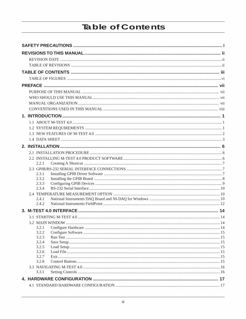
Table of Contents
SAFETY PRECAUTIONS ......................................................................................................................... i
REVISIONS TO THIS MANUAL............................................................................................................... iiREVISION DATE ................................................................................................................................................................. ii
TABLE OF REVISIONS ...................................................................................................................................................... ii
TABLE OF CONTENTS ......................................................................................................................... iiiTABLE OF FIGURES ......................................................................................................................................................... vi
PREFACE .............................................................................................................................................. viiPURPOSE OF THIS MANUAL ........................................................................................................................................ vii
WHO SHOULD USE THIS MANUAL............................................................................................................................. vii
MANUAL ORGANIZATION ............................................................................................................................................ vii
CONVENTIONS USED IN THIS MANUAL .................................................................................................................. viii
1. INTRODUCTION ................................................................................................................................. 11.1 ABOUT M-TEST 4.0 ..................................................................................................................................................... 1
1.2 SYSTEM REQUIREMENTS ........................................................................................................................................ 1
1.3 NEW FEATURES OF M-TEST 4.0 .............................................................................................................................. 2
1.4 DATA SHEET ................................................................................................................................................................ 3
2. INSTALLATION................................................................................................................................... 62.1 INSTALLATION PROCEDURE ................................................................................................................................... 6
2.2 INSTALLING M-TEST 4.0 PRODUCT SOFTWARE.................................................................................................. 62.2.1 Creating A Shortcut ......................................................................................................................................... 7
2.3 GPIB/RS-232 SERIAL INTERFACE CONNECTIONS ............................................................................................... 72.3.1 Installing GPIB Driver Software ..................................................................................................................... 72.3.2 Installing the GPIB Board ............................................................................................................................... 82.3.3 Configuring GPIB Devices .............................................................................................................................. 92.3.4 RS-232 Serial Interface .................................................................................................................................. 10
2.4 TEMPERATURE MEASUREMENT OPTION .......................................................................................................... 102.4.1 National Instruments DAQ Board and NI-DAQ for Windows ...................................................................... 102.4.2 National Instruments FieldPoint .................................................................................................................... 12
3. M-TEST 4.0 INTERFACE .................................................................................................................. 143.1 STARTING M-TEST 4.0 ............................................................................................................................................. 14
3.2 MAIN WINDOW ......................................................................................................................................................... 143.2.1 Configure Hardware ...................................................................................................................................... 143.2.2 Configure Software ........................................................................................................................................ 153.2.3 Run Test ......................................................................................................................................................... 153.2.4 Save Setup ...................................................................................................................................................... 153.2.5 Load Setup ..................................................................................................................................................... 153.2.6 Load File ........................................................................................................................................................ 153.2.7 Exit ................................................................................................................................................................. 153.2.8 Control Buttons .............................................................................................................................................. 15
3.3 NAVIGATING M-TEST 4.0 ........................................................................................................................................ 163.3.1 Setting Controls ............................................................................................................................................. 16
4. HARDWARE CONFIGURATION ...................................................................................................... 174.1 STANDARD HARDWARE CONFIGURATION ........................................................................................................ 17

iv
Magtrol M-TEST 4.0 Motor Testing SoftwareTable of Contents
4.1.1 Password Protection ....................................................................................................................................... 184.1.2 Power Supply ................................................................................................................................................. 184.1.3 Power Measurement ...................................................................................................................................... 194.1.4 Controller ....................................................................................................................................................... 204.1.5 Temperature Measurement ............................................................................................................................ 21
4.2 ADVANCED HARDWARE CONFIGURATION ....................................................................................................... 224.2.1 Channels ........................................................................................................................................................ 234.2.2 Alarms............................................................................................................................................................ 254.2.3 Active Channel .............................................................................................................................................. 254.2.4 Load Defaults ................................................................................................................................................. 25
5. SELECTING A TEST ........................................................................................................................ 265.1 RAMP TESTING ......................................................................................................................................................... 26
5.1.1 Old Measuring Methods ................................................................................................................................ 265.1.2 New Measuring Methods ............................................................................................................................... 26
5.2 CURVE TESTING ....................................................................................................................................................... 31
5.3 MANUAL TESTING ................................................................................................................................................... 33
5.4 PASS/FAIL TESTING ................................................................................................................................................. 33
6. SOFTWARE CONFIGURATION ....................................................................................................... 386.1 PASSWORD PROTECTION ....................................................................................................................................... 38
6.2 TEST ............................................................................................................................................................................ 39
6.3 CONTROLLER............................................................................................................................................................ 39
6.4 DATA LOGGING ........................................................................................................................................................ 40
6.5 CURVE/MANUAL TEST PARAMETERS ................................................................................................................ 426.5.1 Control Data ................................................................................................................................................... 44
6.6 RAMP TEST PARAMETERS ..................................................................................................................................... 456.6.1 Data Points ..................................................................................................................................................... 48
6.7 PASS/FAIL TEST PARAMETERS............................................................................................................................. 49
6.8 CONFIGURE DISPLAY.............................................................................................................................................. 51
6.9 CONFIGURE REPORT ............................................................................................................................................... 536.9.1 Sample Report ............................................................................................................................................... 55
6.10ADJUST CONTROLLER ............................................................................................................................................ 56
7. RUNNING A TEST ............................................................................................................................ 597.1 HARDWARE TEST CONFIGURATION.................................................................................................................... 59
7.2 SOFTWARE TEST CONFIGURATION ..................................................................................................................... 597.2.1 Curve Test ...................................................................................................................................................... 597.2.2 Ramp Test ...................................................................................................................................................... 607.2.3 Manual Test .................................................................................................................................................... 617.2.4 Pass/Fail Test .................................................................................................................................................. 61
7.3 ADJUSTING THE CONTROLLER ............................................................................................................................ 627.3.1 Adjusting the Controller for a Curve Test ..................................................................................................... 627.3.2 Adjusting the Controller for a Ramp Test ...................................................................................................... 65
8. DATA OUTPUT ................................................................................................................................. 688.1 DISPLAY ..................................................................................................................................................................... 69
8.2 SCREEN PLOT ............................................................................................................................................................ 71
8.3 FILE SAVE .................................................................................................................................................................. 74
8.4 RETURN ...................................................................................................................................................................... 74
8.5 LOAD FILE ................................................................................................................................................................. 75

v
Magtrol M-TEST 4.0 Motor Testing Software Table of Contents
9. TROUBLESHOOTING ...................................................................................................................... 76
APPENDIX A: PID/SCALING ............................................................................................................... 77A.1 ABOUT THE PID LOOP ............................................................................................................................................ 77
A.1.1 P (Proportional Gain) ..................................................................................................................................... 77A.1.2 I (Integral) ...................................................................................................................................................... 77A.1.3 D (Derivative) ................................................................................................................................................ 77
A.2 HOW THE PID LOOP WORKS .................................................................................................................................. 78A.2.1 PID Scaling for Hysteresis, Eddy-Current and Powder Brake Dynamometers ............................................ 78A.2.2 Speed Correction for WB (Eddy-Current Brake) Dynamometers ................................................................. 78A.2.3 Equations ....................................................................................................................................................... 79
A.3 PID SCALING ............................................................................................................................................................. 79
A.4 DYNAMIC PI SCALING ............................................................................................................................................ 79A.4.1 Setting the PID for Ramp Down .................................................................................................................... 79
APPENDIX B: M-TEST 4.0 FLOW CHART.......................................................................................... 82
APPENDIX C: SOFTWARE REVISION HISTORY ............................................................................... 83
INDEX .................................................................................................................................................... 87
MAGTROL LIMITED WARRANTY ........................................................................................................ 89CLAIMS .............................................................................................................................................................................. 89

vi
Magtrol M-TEST 4.0 Motor Testing SoftwareTable of Contents
TABLE OF FIGURESCHAPTER 2
Figure 2–1 M-TEST 4.0 Installation ............................................................................................................................ 6Figure 2–2 GPIB Driver Software Main Menu ............................................................................................................ 7Figure 2–3 NI-488.2 Troubleshooting Wizard .............................................................................................................. 8Figure 2–4 System Properties & GPIB Interfaces Properties .................................................................................... 9
CHAPTER 3Figure 3–1 Main Window ........................................................................................................................................... 14Figure 3–2 Inaccessible Controls Example ............................................................................................................... 16
CHAPTER 4Figure 4–1 Configure Hardware Window .................................................................................................................. 17Figure 4–2 Advanced Configuration Window ............................................................................................................ 22
CHAPTER 5Figure 5–1 Average-D/U Motor Curve Before Inertial Cancellation ....................................................................... 27Figure 5–2 Average-D/U Motor Curve ...................................................................................................................... 28Figure 5–3 Correction Factor Calculation ................................................................................................................ 29Figure 5–4 Dynamic-CF Test Before Inertial Cancellation ...................................................................................... 30Figure 5–5 Dynamic-CF Test ..................................................................................................................................... 31Figure 5–6 Torque Curve Setup Example .................................................................................................................. 32Figure 5–7 Torque Curve Test Example ..................................................................................................................... 33Figure 5–8 Pass/Fail Test Example ............................................................................................................................ 34Figure 5–9 Pass/Fail Test Run Window ...................................................................................................................... 35Figure 5–10 Pass/Fail Test Results Window ................................................................................................................. 35Figure 5–11 Failed Test Example ................................................................................................................................. 36Figure 5–12 Microsoft Excel Data File ....................................................................................................................... 37
CHAPTER 6Figure 6–1 Configure Software Window .................................................................................................................... 38Figure 6–2 Curve Test Setup Window ......................................................................................................................... 42Figure 6–3 Manual Test Setup Window ...................................................................................................................... 42Figure 6–4 Ramp Test Setup Window ......................................................................................................................... 45Figure 6–5 Pass/Fail Test Setup Window ................................................................................................................... 49Figure 6–6 Configure Display Window ...................................................................................................................... 51Figure 6–7 Configure Report Window ........................................................................................................................ 53Figure 6–8 Sample Motor Test Report ....................................................................................................................... 55Figure 6–9 Adjust Dynamometer Controller Window ............................................................................................... 56
CHAPTER 7Figure 7–1 Test Window Example .............................................................................................................................. 60Figure 7–2 Curve (no I or D) ..................................................................................................................................... 62Figure 7–3 Curve (P at ¼) ......................................................................................................................................... 63Figure 7–4 Curve (with P and I) ................................................................................................................................ 63Figure 7–5 Matched Curve ......................................................................................................................................... 64Figure 7–6 Ramp (with bump and offset) ................................................................................................................... 65Figure 7–7 Ramp (with bump) .................................................................................................................................... 66Figure 7–8 Ramp (no bump but unstable) .................................................................................................................. 66Figure 7–9 Ramp (no bump and stable) ..................................................................................................................... 67Figure 7–10 Final Ramp ............................................................................................................................................... 67
CHAPTER 8Figure 8–1 Test Window with Data Ouput Options ................................................................................................... 68Figure 8–2 Display Window ....................................................................................................................................... 69Figure 8–3 Configure Print Window .......................................................................................................................... 70Figure 8–4 Graph Setup Window ............................................................................................................................... 71Figure 8–5 Graph Without Curve Fit ......................................................................................................................... 72Figure 8–6 Graph With Curve Fit .............................................................................................................................. 73Figure 8–7 Save As Dialog Box .................................................................................................................................. 74Figure 8–8 Load File Data Output ............................................................................................................................. 75
APPENDIX AFigure A–1 System Block Diagram ............................................................................................................................. 78Figure A–2 Ramp Down Low I .................................................................................................................................... 80Figure A–3 Ramp Down High I .................................................................................................................................. 80Figure A–4 Ramp Down Dynamic I ............................................................................................................................ 81

vii
PURPOSE OF THIS MANUAL
This manual contains information required for installation and general use of Magtrol's M-TEST4.0 Motor Testing Software. To achieve maximum capability and ensure proper use, please readthis manual in its entirety before operating. Keep the manual in a safe place for quick referencewhenever a question should arise.
WHO SHOULD USE THIS MANUAL
This manual is intended for those operators in need of a software program to complement theirMagtrol test equipment setup. The setup may include any of the following Magtrol products:
• Hysteresis, Eddy-Current or Powder Brake Dynamometer
• In-Line Torque Transducer
• Power Analyzer (Model 5100, 5300, 6510, 6510e, 6530 or 6550)
• Dynamometer Controller (Model DSP6000, DSP6001, 5240 or 4629B)
Optional auxiliary instrumentation can also be utilized. If using a DC power supply, it may be usedin place of a power analyzer to read back amps and volts but is not recommended because thereadings are less accurate and the data transfer rates are substantially slower.
MANUAL ORGANIZATION
This section gives an overview of the structure of the manual and the information contained withinit. Some information has been deliberately repeated in different sections of the document to minimizecross-referencing and to facilitate understanding through reiteration.
The structure of the manual is as follows:
Chapter 1: INTRODUCTION – Contains the technical data sheet for M-TEST 4.0 and highlightsthe new features of the software.
Chapter 2: INSTALLATION – Provides general installation instructions for M-TEST 4.0product software, GPIB/RS-232 interface, and temperature measurement driversoftware and hardware.
Chapter 3: M-TEST 4.0 INTERFACE – Provides instruction for M-TEST 4.0 startup andnavigation and includes a brief overview of the software capabilities.
Chapter 4: HARDWARE CONFIGURATION – Contains the information needed to programM-TEST 4.0 software with details pertaining to the hardware being utilized in thetest setup.
Chapter 5: SELECTING A TEST – Describes the different testing options M-TEST 4.0 hasavailable for easier test selection.
Chapter 6: SOFTWARE CONFIGURATION – Provides information required to configureM-TEST 4.0 for the type of test to be performed.
Chapter 7: RUNNING A TEST – Step-by-step instructions for setting up and running a basiccurve, ramp, manual and pass/fail test from beginning to end.
Preface

viii
Magtrol M-TEST 4.0 Motor Testing SoftwarePreface
Chapter 8: DATA OUTPUT – Describes the data output options available to the user alongwith providing instruction for use.
Chapter 9: TROUBLESHOOTING – Solutions to common problems encountered during setupand testing.
Appendix A: PID/SCALING – Describes the Proportional Integral Derivative (PID) Loop andScaling and provides information on theory.
Appendix B: M-TEST 4.0 FLOW CHART – Representation of how M-TEST 4.0 is organizedshowing at a quick glance where all the main features are located.
Appendix C: SOFTWARE REVISION HISTORY – Provides a detailed description of all changesthat have been made to Magtrol's M-TEST 4.0 Motor Testing Software since itsinitial release.
CONVENTIONS USED IN THIS MANUAL
The following symbols and type styles may be used in this manual to highlight certain parts of thetext:
Note: This is intended to draw the operator’s attention to complementaryinformation or advice relating to the subject being treated. Itintroduces information enabling the correct and optimal functioningof the product to be obtained.
CAUTION: THIS IS USED TO DRAW THE OPERATOR’S ATTENTION TO INFORMATION,DIRECTIVES, PROCEDURES, ETC. WHICH, IF IGNORED, MAY RESULT IN DAMAGE
BEING CAUSED TO THE MATERIAL BEING USED. THE ASSOCIATED TEXT
DESCRIBES THE NECESSARY PRECAUTIONS TO TAKE AND THE CONSEQUENCES
THAT MAY ARISE IF THE PRECAUTIONS ARE IGNORED.
WARNING! THIS INTRODUCES DIRECTIVES, PROCEDURES,PRECAUTIONARY MEASURES, ETC. WHICH MUST BEEXECUTED OR FOLLOWED WITH THE UTMOST CAREAND ATTENTION, OTHERWISE THE PERSONALSAFETY OF THE OPERATOR OR THIRD PARTY MAYBE PUT AT RISK. THE READER MUST ABSOLUTELYTAKE NOTE OF THE ACCOMPANYING TEXT, AND ACTUPON IT, BEFORE PROCEEDING FURTHER.

1
GE
NE
RA
LIN
FO
RM
AT
ION
1. Introduction
1.1 ABOUT M-TEST 4.0
Magtrol's M-TEST 4.0 Software is a state-of-the-art motor testing program for Windows®-baseddata acquisition. Used in conjunction with Magtrol's Motor Testing Equipment, M-TEST 4.0 providestesting and data options to help determine the performance and characteristics of a motor under test.The data generated by the program can then be stored, displayed and printed in tabular or graphicformats, and easily imported into a spreadsheet. M-TEST 4.0 is ideal for tasks such as simulatingloads, cycling the unit under test and motor ramping.
M-TEST 4.0 is equipped to work in conjunction with any of the following Magtrol motor testinginstruments:
• Dynamometer Controller (Model DSP6001, DSP6000, 5240 or 4629B)
• Hysteresis, Eddy-Current or Powder Brake Dynamometer
• In-Line Torque Transducer
• Power Analyzer (Model 5100, 5300, 6510, 6510e, 6530 or 6550)
Note: If using a DC power supply, it may be used in place of a poweranalyzer to read back amps and volts but is not recommendedbecause the readings are less accurate and the data transfer ratesare substantially slower.
Written in LabVIEW™, M-TEST 4.0 has the flexibility to test a majority of motor types in avariety of ways. Because of LabVIEW's versatility, obtaining data from other sources (e.g.thermocouples), controlling motor power and providing audio/visual indicators is relatively easy.These inputs usually require the addition of a National Instruments™ data acquisition board to yourcomputer.
If you have a specialized test that you wish to perform, contact Magtrol Technical Assistance at716-668-5555.
1.2 SYSTEM REQUIREMENTS
• Personal computer with Pentium® processor or equivalent
• Microsoft® Windows® 9x/Me/NT/2000/XP
• 32 MB of RAM
• 100 MB of available hard drive space
• VGA color monitor with screen resolution set at 800 × 600• Parallel port laser or color ink jet printer
• National Instruments™ PCI-GPIB card and NI-488.2™ Software for Windows® isrecommended for interfacing between computer and peripherals
• RS-232 serial interface can be used, instead of the PCI-GPIB card, for interfacing withMagtrol DSP6000 or DSP6001 controllers
• National Instruments™ DAQ Board and NI-DAQ™ for Windows® or National Instruments™FieldPoint hardware and software, required only with MT-TEST 4.0 Software

2
Magtrol M-TEST 4.0 Motor Testing SoftwareChapter 1 – Introduction
GE
NE
RA
LIN
FO
RM
AT
ION
1.3 NEW FEATURES OF M-TEST 4.0
Magtrol's M-TEST 4.0 Software is a new and improved motor testing program that replaces M-TEST 3.1. The software is comprised of many new features that make it unique.
• Increased Product Support Capabilities: Equipped to handle a wider range of Magtrolproducts including Dynamometer Controllers (DSP6001, 6000, 5240 and 4629B); Hysteresis,Eddy-Current and Powder Brake Dynamometers (including Tandem Dynamometers); PowerAnalyzers (Model 5100, 5300, 6510, 6510e, 6530 and 6550) and In-Line Torque Transducers.
• Automatic Load Defaults Option: When configuring the hardware settings, there is anoptional load default feature that will automatically download the parameters of theDynamometer being used based on the model number.
• Multiple Testing Options: 4 standard test options include:
(1) Ramp – Ramp down with inertia correction factor or average ramp down/ramp up. Theramp test also allows extrapolation of free-run and locked rotor data, plus interpolationof specific speed or torque data points.
(2) Curve – Parameters include speed, torque, amps, watts input, watts output and openloop. Capable of adjusting sampling rate and using step or ramp from one load point tothe next.
(3) Manual – Test is conducted through the front panel of the Dynamometer Controllerwhile the computer is used solely for the purpose of data acquisition. The manual testallows adjustment of the sampling rate.
(4) Pass/Fail – Checks amps, input watts (with optional Power Analyzer), speed, torqueand output watts against user defined values.
• Dynamic PID Scaling: Produces consistent control loop results throughout motor speedrange while running a ramp test, making for a better overall system response (for DSP6001only).
• PID Adjustment Routines: Helps adjust the system properly for ramp and step functions.• Motor Shaft Direction Indicator: Indicates if the motor is turning clockwise or
counterclockwise.
• Graphing Capabilities: Tested parameters are displayed as a single graph with multiplecurves that are easy-to-read with the use of colored and labeled plots. Screen plot axes canbe manually scaled.
• Save/Load Setup Function: Test procedure configurations may be stored and recalledusing standard Windows® file structure.
• Three-Phase Power Analyzer Data Acquisition: Can obtain data on each individualphase and/or the sum used in the chosen parameters (amps, volts, input watts and powerfactor).

3
Magtrol M-TEST 4.0 Motor Testing Software Chapter 1 – Introduction
GE
NE
RA
LIN
FO
RM
AT
ION
1.4 DATA SHEET
M-TEST 4.0Motor Testing Software
FEATURES• Automatic Load Defaults Option: Downloads testing
instrument parameters based on model number.• Multiple Testing Options:
Ramp: Average ramp down/ramp up or ramp down withinertia correction factor. Also allows extrapolationof free-run and locked rotor data, plus interpolationof specific speed or torque data points.
Curve: Speed, torque, amps, watts input, watts output and openloop parameters. Capable of adjusting sampling rateand using step or ramp from one load point to the next.
Manual: Runs test from front panel of the DynamometerController while computer acquires data. Allowsadjustment of sampling rate.
Pass/Fail:Checks amps, input watts (with optional PowerAnalyzer), speed, torque and output watts againstuser defined values.
• Dynamic PID Scaling: Provides consistent control loop resultsthroughout motor speed range during ramp test (for DSP6001 only).
• PID Adjustment Routines: Helps adjust the system for rampand step functions.
• Motor Shaft Direction Indicator: Indicates if the motor isturning clockwise or counterclockwise.
• Graphing Capabilities: Single graph with multiple curves;Easy-to-read colored and labeled plots; Manual scaling.
• Save/Load Setup Function: Test procedure configurationsmay be stored and recalled using standard Windows® file structure.
• Three Phase Power Analyzer Data Acquisition: Obtain data on each individualphase and/or the sum used in the chosen parameters (amps, volts, input wattsand power factor).
• IEEE-488 and RS-232 Interface: Computer interface with NationalInstruments™ PCI GPIB. RS-232 available with DSP6001 and DSP6000 only.
• Displays 11 Tested and Calculated Parameters: Torque, speed and auxiliaryinput are displayed from the DSP6001, DSP6000, 5240 or 4629B Controller; amps,volts and watts from the Power Analyzer (optional). Calculated values includinghorsepower, efficiency, power factor, output watts and time can also be displayed.
• Customized Reports: Allows user to produce a one-page motor test summarywhich can include the motor's serial number; maximum torque, speed, powerand current values; operator name; time and date of test; motor direction; 32data points and an X-Y plot.
• Curve Fitting: A curve fitting routine can be applied to most motor test curves. M-TEST 4.0 Customized Report
Magtrol, Inc.
40
0
5
10
15
20
25
30
35
20000 500 1000 1500
Test Time:
Serial Number:
Operator Code:
Maximum Efficiency:
Maximum Torque:
Direction of Rotation:
This page displays a typical report that can be generated from M-TEST.
Comments
OzIn
RPM
Test Date:
Speed OzIn Amps 1 Volts 1 Input Watts 1 Power Factor 1 Efficiency Output Watts Horsepower
1795.304 0.000 0.290 119.358 27.245 0.793 0.000 0.000 0.000
1770.000 5.151 0.311 119.235 32.172 0.868 0.210 6.741 0.009
1699.000 18.960 0.383 119.070 43.508 0.954 0.548 23.821 0.032
1648.000 26.276 0.451 118.904 51.474 0.960 0.622 32.022 0.043
1598.000 30.918 0.509 118.775 57.909 0.959 0.631 36.536 0.049
1545.000 33.810 0.558 118.658 63.425 0.957 0.609 38.628 0.052
1500.000 35.310 0.593 118.607 67.254 0.957 0.582 39.167 0.053
1452.000 36.045 0.622 118.573 70.778 0.960 0.547 38.703 0.052
1403.000 36.300 0.649 118.573 72.616 0.944 0.519 37.661 0.051
1358.000 36.157 0.673 118.591 74.454 0.933 0.488 36.310 0.049
1314.000 35.733 0.688 118.517 76.293 0.936 0.455 34.721 0.047
1261.000 35.121 0.712 118.517 78.131 0.927 0.419 32.750 0.044
1213.000 34.316 0.727 118.371 79.969 0.929 0.385 30.782 0.041
1159.000 33.462 0.743 118.389 80.889 0.919 0.355 28.680 0.038
1111.000 32.631 0.757 118.426 81.808 0.912 0.328 26.809 0.036
1069.000 31.924 0.769 118.446 82.727 0.908 0.305 25.236 0.034
1012.000 31.030 0.775 118.573 84.565 0.920 0.275 23.222 0.031
963.000 30.076 0.794 118.573 84.565 0.898 0.253 21.418 0.029
905.000 29.151 0.798 118.610 85.301 0.901 0.229 19.509 0.026
854.000 28.080 0.808 118.609 86.404 0.902 0.205 17.733 0.024
793.000 27.100 0.821 118.573 86.404 0.888 0.184 15.892 0.021
745.000 26.055 0.824 118.371 86.404 0.886 0.166 14.354 0.019
690.000 25.165 0.826 118.316 87.323 0.894 0.147 12.840 0.017
627.000 24.272 0.830 118.371 87.323 0.888 0.129 11.254 0.015
563.000 22.927 0.845 118.426 88.242 0.882 0.108 9.545 0.013
509.000 22.047 0.847 118.371 88.242 0.881 0.094 8.298 0.011
445.000 21.927 0.849 118.334 88.242 0.879 0.082 7.216 0.010
394.000 21.225 0.850 118.352 88.242 0.878 0.070 6.184 0.008
328.000 20.502 0.853 118.444 89.162 0.883 0.056 4.973 0.007
256.000 19.581 0.855 118.426 90.081 0.890 0.041 3.707 0.005
204.000 19.340 0.859 118.426 90.081 0.885 0.032 2.918 0.004
0.000 17.558 0.870 118.379 92.395 0.897 0.000 0.000 0.000
5/8/01
12:18:22 PM
0001
TRW
0.633271
36.330000
CW
M-TEST 4.0 Software Configuration
M-TEST 4.0 Graphical Data Output

4
Magtrol M-TEST 4.0 Motor Testing SoftwareChapter 1 – Introduction
GE
NE
RA
LIN
FO
RM
AT
ION
Specifications M-TEST 4.0
SYSTEM CONFIGURATIONA Magtrol Dynamometer provides motor loading with a Magtrol Programmable Dynamometer Controller acting asthe interface between the personal computer running M-TEST 4.0 and the Dynamometer. If motor electrical parametersare to be measured or used to determine load points, a Magtrol Power Analyzer is also required. Interfacing betweenthe computer and electronic instrumentation is by the National Instruments™ PCI-GPIB card or serial interface whenusing a DSP6000 or DSP6001.
DESCRIPTIONUsed with a Magtrol DSP6000/6001, 5240 or 4629BDynamometer Controller, Magtrol M-TEST 4.0 Softwareprovides the control of any Magtrol Dynamometer andruns test sequences in a manner best suited to the overallaccuracy and efficiency of the Magtrol Motor TestSystem. M-TEST 4.0 is equipped to handle a wider rangeof Magtrol products including Dynamometer Controllers(DSP6001, DSP6000, 5240 and 4629B); Hysteresis,Eddy-Current, Powder Brake and TandemDynamometers; Power Analyzers (Model 5100, 5300,6510, 6510e, 6530 and 6550) and In-Line TorqueTransducers. The data that is generated by Magtrol'sMotor Testing Software can be stored, displayed andprinted in tabular or graphic formats, and can be easilyimported into a spreadsheet.
Written in LabVIEW™, M-TEST 4.0 has the flexibility totest a majority of motor types in a variety of ways. Becauseof LabVIEW's versatility, obtaining data from other sources(e.g. thermocouples), controlling motor power and providingaudio/visual indicators is relatively easy.
SYSTEM REQUIREMENTS• Personal computer with Pentium® processor or
equivalent• Microsoft® Windows® 9x/Me/NT/2000/XP• 32 MB of RAM• 100 MB of available hard drive space• VGA color monitor with screen resolution set at
800 × 600• Parallel port laser or color ink jet printer• National Instruments™ PCI-GPIB card (available
from Magtrol) and NI-488.2™ Software forWindows® is recommended for interfacingbetween computer and peripherals
• RS-232 serial interface can be used, instead of thePCI-GPIB card, for interfacing with MagtrolDSP6000 or DSP6001 controllers
• National Instruments™ FieldPoint hardware(preferred) or National Instruments™ DAQ Board,required only with MT-TEST 4.0 Software
TEMPERATURE MEASUREMENTMT-TEST 4.0 (sold separately) is a version of M-TEST 4.0that allows the user to perform temperature measurementtesting. The software provides complete dynamometercontrol, allowing for temperature measurement whileperforming load simulation for duty cycle and life testing.Temperature measurement is ideal for performing heat risecurves on different areas of a motor such as the bearings,windings and housing. All other features of MT-TEST 4.0are the same as M-TEST 4.0.
APPLICATIONSMagtrol's M-TEST 4.0 Software is ideal for simulatingloads, cycling the unit under test and motor ramping.Because it is easy to gather data and duplicate tests, thesoftware is ideal for use in engineering labs. Tests canbe programmed to run on their own and saved for futureuse allowing for valuable time savings in productiontesting and incoming/outgoing inspection.
PC
M–TEST4.0
Motor Under Test Hysteresis Dynamometer
Junction Box(SCB-68)or Board
(AMUX-64T)
Motor PowerSource
DSP6001Programmable Controller
6510e or 6530Power Analyzer(optional)
Thermocouples(31 maximum with AMUX-64T,
7 maximum with SCB-68)
Cable to DataAcquisition Card
GPIBCable
GPIBCable
GPIBCard
DataAcquisition
Card(DAQ Board)
MODEL 6510POWER ANALYZER
MODEL DSP6001DYNAMOMETER CONTROLLER
Components in shaded boxapply to TemperatureMeasurement Option
(MT-TEST 4.0) only
PC
Motor Under Test
Thermocouples(8 per module, 32 max.)
SerialCable
GPIBCard
SerialPort
PowerSupply
FP-1000network
interface &
FP-TC-120-xthermocoupleinput module
Preferred MT-Test Option: Utilizing theFieldPoint thermocouple input module(s) (upto 4) and network interface card connectedto the serial port, in place of the junction box/board and data acquisition card (DAQboard).

5
Magtrol M-TEST 4.0 Motor Testing Software Chapter 1 – Introduction
GE
NE
RA
LIN
FO
RM
AT
ION
Ordering Information M-TEST 4.0
Due to the continual development of our products, we reserve the right to modify specifications without forewarning.
CUSTOM SOFTWAREMagtrol can make custom modifications to meet your specific requirements. If you wish to modify M-TEST 4.0yourself, you will need to purchase the source code (available from Magtrol) and National Instruments™ LabVIEW™software (available from National Instruments).
NOITPIRCSED #TRAP/LEDOM)V021(eludoMtupnIdetalosIlennahC-8dnaecafretnItnioPdleiF * PF-TSETT-WH
)V042(eludoMtupnIdetalosIlennahC-8dnaecafretnItnioPdleiF * A-PF-TSETT-WH
)esabgnitnuomsedulcni(eludoMelpuocomrehTlennahC-8tnioPdleiFlanoitiddA 869400
xoBnoitcnuJlennahC-886-BCSdnasubASIhtiwdraoBQAD ** ASI-TSETT-WH
xoBnoitcnuJlennahC-886-BCSdnasubICPhtiwdraoBQAD ** ICP-TSETT-WH
draoBnoitcnuJlennahC-23T46-XUMAdnasubAShtiwdraoBQAD ** ASI-TXE-TSETT-WH
draoBnoitcnuJlennahC-23T46-XUMAdnasubICPhtiwdraoBQAD ** ICP-TXE-TSETT-WH
rellortnoCretemomanyDelbammargorP 1006PSD
sretemomanyDsiseretsyH seiresDH ***sretemomanyDtnerruC-yddE seiresBW ***sretemomanyDekarBredwoP seiresBP ***
srecudsnarTeuqroTeniL-nI seiresBMT/SHMT/MT ***rezylanArewoPesahP-elgniS 0156 e
rezylanArewoPesahP-eerhT 0356
rezylanArewoPesahP-eerhTdecnahnE 0556
34dna7.2seiressretemomanyDBP&BWrofylppuSrewoP 013SED
51dna511,56seiresretemomanyDBP&BWrofylppuSrewoP 113SED
retemomanyD528-DHrofylppuSrewoP 1425
renoitidnoCdeepS/euqroT 104CST
BIPG )ICP(draCecafretnI 320M-37
retem1,elbaCBIPG 740M88
sretem2,elbaCBIPG 840M88
elbaCrotcennoCrecudsnarTeuqroT 10/311BE
MTE
STD
S-U
S w
ww
07/
03
SYSTEM OPTIONS AND ACCESSORIES
* Power supply and serial cable are included** A one meter data acquisition cable is included.
MODEL NUMBERS
MODEL NUMBER SOFTWARE DESCRIPTION
SW-M-TEST-WE4.0 Standard M-TEST 4.0 Motor Testing SoftwareSW-M-TEST-WS4.0 Standard M-TEST 4.0 Motor Testing Software–includes source codesSW-MT-TEST-FP-WE4.0 MT-TEST 4.0 Motor Testing Software with Temperature Testing option for FieldPointSW-MT-TEST-FP-WS4.0 MT-TEST 4.0 Motor Testing Software with Temperature Testing option for FieldPoint –
includes source codesSW-MT-TEST-DAQ-WE4.0 MT-TEST 4.0 Motor Testing Software with Temperature Testing option for DAQ BoardSW-MT-TEST-DAQ-WS4.0 MT-TEST 4.0 Motor Testing Software with Temperature Testing option for DAQ Board–
includes source codes
TEST
ING
INST
RU
MEN
TSPO
WER
ANAL
YZER
SC
AB
LE
S
CARDS
PO
WE
RS
UP
PLI
ES
TE
MP
ER
AT
UR
ET
ES
TIN
G H
AR
DW
AR
E
MISC
For information on the most current software release available, refer to Magtrol's Web site at www.magtrol.com/motortesting/software.htm
***Contact Magtrol Customer Service or refer to our web site atwww.magtrol.com for a complete list of models.

6
GE
TT
ING
STA
RT
ED
2. Installation
2.1 INSTALLATION PROCEDURE
The general installation order is as follows.
1. Install M-TEST 4.0 product software.
2. Install GPIB driver software and interface board. If only using a controller in the test setup,the RS-232 serial interface may be used.
3. Install NI-DAQ™ driver software and board if using MT-TEST 4.0.
The remainder of this chapter will provide specific installation instructions for each component ofthe system.
2.2 INSTALLING M-TEST 4.0 PRODUCT SOFTWARE
1. Exit all other programs before installing M-TEST 4.0.
2. Insert the M-TEST 4.0 CD in your CD-ROM drive. The installation process will beginautomatically and the M-TEST 4.0 Installation window will appear.
Figure 2–1 M-TEST 4.0 Installation
3. The default installation directory is C:\Magtrol. To keep the default location, click Finish.Although not recommended, this location can be changed. Click Change and type the newdirectory, then click Finish.
4. The software installation will continue and a message will appear indicating that theinstallation was successful and the computer must be rebooted before running the program.Click OK.
5. An M-TEST 4.0 window will appear displaying the drive:\path where the software programhas been saved. Close this window by clicking the "X" in the upper-right corner and theinstallation process will be complete.

7
Magtrol M-TEST 4.0 Motor Testing Software Chapter 2 – Installation
GE
TT
ING
STA
RT
ED
Note: To run M-TEST 4.0 at this time, you must restart you computer
2.2.1 CREATING A SHORTCUT
For easy access to the M-TEST 4.0 program, a shortcut can be placed on your computer desktop.
1. Start Windows Explorer and locate the directory where the M-TEST 4.0 Software wasinstalled.
2. Click the M-TEST.exe file and drag it to your desktop.
3. To access the program, double-click the shortcut and the program will automatically start.
2.3 GPIB/RS-232 SERIAL INTERFACE CONNECTIONS
The GPIB driver software (NI-488.2™ For Windows® 9x/Me/NT/2000) and interface board (NationalInstruments™ PCI-GPIB), purchased through Magtrol or directly from National Instruments, mustbe installed at this time.
Note: If only using a controller in the test setup, the RS-232 serial interfacemay be used.
2.3.1 INSTALLING GPIB DRIVER SOFTWARE
1. Insert the NI-488.2 Software for Windows CD in your CD-ROM drive. The installation processwill begin automatically and the GPIB Driver Software Main Menu window will appear.
Figure 2–2 GPIB Driver Software Main Menu
2. Click Install NI-488.2 Software for Windows.
3. Click Next.4. Click Yes to accept the National Instruments License Agreement.
5. Click Next to bypass the online registration.

8
Magtrol M-TEST 4.0 Motor Testing SoftwareChapter 2 – Installation
GE
TT
ING
STA
RT
ED
6. Select destination directory and click Next. To use default just click Next.7. Select installation type. The default is recommended.
8. The software is now ready to install. Click Next to begin.
9. NI-VISA dialog box will appear. Click Next.10. Installation is now complete. Click Finish.
11. Click Exit to quit the GPIB Driver Software installation program.
2.3.2 INSTALLING THE GPIB BOARD
1. Shut down your computer.
2. Install the PCI-GPIB controller board in an available expansion slot according to the hardwaremanufacturer’s user documentation.
3. Turn on your computer. The new hardware will automatically be installed and the GettingStarted Wizard will begin.
4. Click verify your hardware and software installation. The Troubleshooting Wizard dialogbox will appear.
Figure 2–3 NI-488.2 Troubleshooting Wizard
5. When the software, hardware and interfaces have been verified, as shown in Figure 2–3 NI-488.2 Troubleshooting Wizard, click Exit.
6. Select the Do not show at Windows startup check box.
7. Close the dialog box by clicking the “X” in the upper-right corner.

9
Magtrol M-TEST 4.0 Motor Testing Software Chapter 2 – Installation
GE
TT
ING
STA
RT
ED
2.3.3 CONFIGURING GPIB DEVICES
1. From the Windows taskbar, click Start, then point to Settings and click Control Panel.2. Double-click System. This will bring up the System Properties dialog box.
Figure 2–4 System Properties & GPIB Interfaces Properties
3. Click the Device Manager tab.
4. Using the right mouse button, click (right-click) National Instruments GPIB Interfaces.
5. Click Properties.6. Click the Device Templates tab. See Figure 2–4 System Properties & GPIB Interfaces
Properties.
7. Scroll down Device Name list until DEV9 is reached.
8. Click DEV9.
9. Set DEV attributes to the following:
a. Under Termination Methods, select the Terminate Read on EOS check box.
b. Change EOS Byte to “10”.
c. Select the Readdress check box.
Note: The only DEV attributes that need to be changed are those that areoutlined in item 9. All other settings should remain in their originalformat.
10. Scroll down Device Name list until DEV12 is reached.
11. Click DEV12.
12. Set DEV12 attributes by repeating steps 9a–c.
13. Scroll down Device Name list until DEV14 is reached.

10
Magtrol M-TEST 4.0 Motor Testing SoftwareChapter 2 – Installation
GE
TT
ING
STA
RT
ED
14. Click DEV14.
15. Set DEV14 attributes by repeating steps 9a–c.
16. After all attributes have been set, click OK on the National Instruments GPIB InterfacesProperties dialog box.
17. Click OK on the System Properties diaolog box.
18. Close the Control Panel window.
19. The GPIB device configuration is complete.
2.3.4 RS-232 SERIAL INTERFACE
M-TEST 4.0 will communicate with the DSP6000/6001 Dynamometer Controller using an RS-232Serial Interface. Connection diagrams and instructions can be found in the following User's Manuals:
• DSP6000 – Section 5.7–Select the Baud Rate for the RS-232 Interface
• DSP6001 – Section 8.2–About the RS-232 Interface
2.4 TEMPERATURE MEASUREMENT OPTION
MT-TEST 4.0 (sold separately) is a version of M-TEST 4.0 that allows the user to perform temperaturemeasurement testing. The feature provides complete dynamometer control, allowing for temperaturemeasurement while performing load simulation for duty cycle and life testing. All other features ofMT-TEST 4.0 are identical to those in M-TEST 4.0. If using MT-TEST 4.0, additional hardwareand software must be installed. The options, which may be purchased from either Magtrol orNational Instruments include:
• National Instruments™ DAQ Board and NI-DAQ™ for Windows® or
• National Instruments™ FieldPoint
2.4.1 NATIONAL INSTRUMENTS DAQ BOARD AND NI-DAQ FOR WINDOWS
Features:• 7 thermocouple inputs with SCB-68, 31 thermocouple inputs with AMUX-64T
• Non-isolated
• Non-filtered
2.4.1.1 Installing Driver Software1. Insert the National Instruments NI-DAQ for Windows 2000/NT/9x/XP and Mac OS Data
Acquisition Software CD in your CD-ROM drive. The installation process will automaticallybegin.
2. When the introductory window appears, click Install.3. Read the Welcome Page and click Next.4. Read the notes and click Next.5. Read the License Agreement and click Yes.
6. To use defaults, click Next.7. The Selection Confirmation dialog box will appear. Click Next.8. The software installation will continue and the Installation Status dialog box will appear
when finished. Click Restart Later. (You will shut down your computer prior to installingthe Temperature Board).

11
Magtrol M-TEST 4.0 Motor Testing Software Chapter 2 – Installation
GE
TT
ING
STA
RT
ED
2.4.1.2 Installing Board1. Shut down your computer.
2. Install the National Instruments PCI-6024E Multifunction I/O board in an available expansionslot according to the hardware manufacturer’s user documentation.
3. Turn on your computer. The new hardware will automatically be installed and the NI-DAQDocumentation Setup program will start.
4. Select the If you do not want to install documents now, check this box check box.
5. Click Next.6. Select the Configure Measurement & Automation System is selected check box.
7. Click Finish.
8. Under User Preferences, click OK.
9. In MAX (Measurement & Automation Explorer) window, double-click Devices andInterfaces.
10. Right-click PCI-6024E.11. Click Properties.
12. Click the Accessory tab.
13. Click inside the Accessory box and drag down to the desired selection. Options include:
• SCB-68 for hardware that allows up to 7 thermocouples. (HW-TTEST)
• AMUX-64T(1) for hardware that allows up to 31 thermocouples. (HW-TTEST-EXT)
14. Select the CJC Jumper Set check box.
15. Click Apply.
16. Click OK.
17. Close MAX window.
2.4.1.3 Thermocouple Connections
Following are basic instructions for installing thermocouple connections. For more detailedinformation, refer to the instruction materials enclosed with the hardware.
2.4.1.3.1 SCB-681. Open the SCB-68 Connector Box to expose the terminal blocks.
2. The pair of terminals associated with Channel 0 are being used by the cold junctioncompensation sensor. Install thermocouples beginning at Channel 1.
3. When all are attached, route the wires out through the opening in the front panel and securethem with the hold down bar.
4. Close the cover.
5. Connect the 68-pin shielded cable assembly between the connector box and the dataacquisition board.
Following is a list of channels with the corresponding terminals.
slennahC slanimreT1 66,332 13,563 36,034 16,825 62,066 85,527 32,75

12
Magtrol M-TEST 4.0 Motor Testing SoftwareChapter 2 – Installation
GE
TT
ING
STA
RT
ED
2.4.1.3.2 AMUX-64T1. The pair of terminals associated with Channel 0 are being used by the cold junction
compensation sensor. Install thermocouples beginning at Channel 1.
2. Connect the 68-pin shielded cable assembly between the AMUX-64T board and the dataacquisition board.
2.4.2 NATIONAL INSTRUMENTS FIELDPOINT
Features:
• 8 thermocouple inputs per module x 4 modules = 32 thermocouples maximum
• Built-in voltage isolation on all channels
• Filtering reduces electrical noise associated with putting thermocouples on motors
• Connects to computer through RS-232 serial port
2.4.2.1 Installing Driver Software1. Insert the National Instruments FieldPoint Software CD in your CD-ROM drive. The
FieldPoint Setup process will automatically begin.
2. When the introductory window appears, click Install.3. Read the Software License Agreement and click Yes.
4. To use the default Destination Location, click Next. If you prefer to change your DestinationLocation, click Browse, choose a new folder, click OK, then click Next.
5. Select desired Setup Type, then click Next.6. FieldPoint Setup will automatically add program icons to the Program Folder. You may
type a new folder name or select one from the existing Folders list. Click Next to continue.
7. At this time FieldPoint Setup has enough information to start copying the program files. Toreview or change any setting, click Back. If you are satisfied with the settings, click Nextto begin copying files.
8. FieldPoint Setup has finished copying files to your computer. Click No, I will restart mycomputer later, (you will shut down your computer prior to installing the hardware) removeany disks from their drives, then click Finish to complete setup.
2.4.2.2 Installing Hardware1. Shut down your computer.
2. Connect the FP-1000 RS-232/RS-485 network interface to the FP-TC-120 8-channelthermocouple input module(s).
3. Connect a power supply to the network interface with the positive lead to the V terminal andthe negative lead to the C terminal.
4. Connect the serial cable from the network interface to COM1 serial port on the computer.
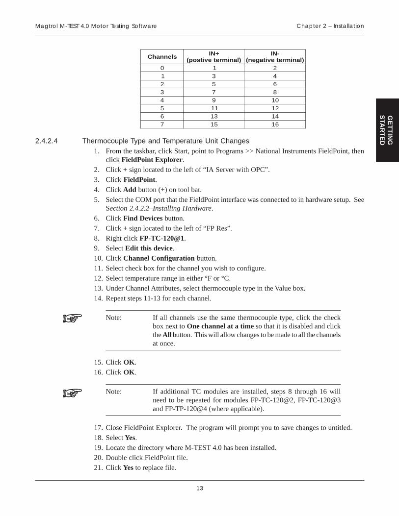
2.4.2.3 Thermocouple Connections1. Install thermocouples beginning at Channel 0.
Following is a list of channels with the corresponding terminals.
13
Magtrol M-TEST 4.0 Motor Testing Software Chapter 2 – Installation
GE
TT
ING
STA
RT
ED
slennahC +NI)lanimretevitsop(
-NI)lanimretevitagen(
0 1 21 3 42 5 63 7 84 9 015 11 216 31 417 51 61
2.4.2.4 Thermocouple Type and Temperature Unit Changes1. From the taskbar, click Start, point to Programs >> National Instruments FieldPoint, then
click FieldPoint Explorer.
2. Click + sign located to the left of “IA Server with OPC”.
3. Click FieldPoint.4. Click Add button (+) on tool bar.
5. Select the COM port that the FieldPoint interface was connected to in hardware setup. SeeSection 2.4.2.2–Installing Hardware.
6. Click Find Devices button.
7. Click + sign located to the left of “FP Res”.
8. Right click [email protected]. Select Edit this device.
10. Click Channel Configuration button.
11. Select check box for the channel you wish to configure.
12. Select temperature range in either °F or °C.
13. Under Channel Attributes, select thermocouple type in the Value box.
14. Repeat steps 11-13 for each channel.
Note: If all channels use the same thermocouple type, click the checkbox next to One channel at a time so that it is disabled and clickthe All button. This will allow changes to be made to all the channelsat once.
15. Click OK.
16. Click OK.
Note: If additional TC modules are installed, steps 8 through 16 willneed to be repeated for modules FP-TC-120@2, FP-TC-120@3and FP-TP-120@4 (where applicable).
17. Close FieldPoint Explorer. The program will prompt you to save changes to untitled.
18. Select Yes.
19. Locate the directory where M-TEST 4.0 has been installed.20. Double click FieldPoint file.
21. Click Yes to replace file.

14
GE
TT
ING
STA
RT
ED
3. M-TEST 4.0 Interface
3.1 STARTING M-TEST 4.0
From the taskbar, click Start, point to Programs >> M-TEST 4.0, then click M-Test. If youcreated a shortcut on your desktop (see Section 2.1.1–Creating A Shortcut), double-click the desktopfile and the program will automatically start.
3.2 MAIN WINDOW
When the program is open, the Main window will appear.
Figure 3–1 Main Window
The Main window contains buttons that lead to 7 different areas of the M-TEST 4.0 program.Following is a brief description of the functions of each area.
3.2.1 CONFIGURE HARDWARE
• Configures the system for the hardware being used including information pertaining to thepower supply, controller, power measurement and temperature measurement.
• Includes a link to the Advanced Configuration window for setting the type of testinginstrument(s) being used along with corresponding specifications.
15
Magtrol M-TEST 4.0 Motor Testing Software Chapter 3 – M-TEST 4.0 Interface
GE
TT
ING
STA
RT
ED
3.2.2 CONFIGURE SOFTWARE
• Configures the system for the type of test to be performed.
• Sets up the corresponding test parameters.
• Includes links to configure the display and report, and adjust the controller.
3.2.3 RUN TEST
• Executes the test after the hardware and software configuration is complete or after retrievinga previous setup.
3.2.4 SAVE SETUP
• After a test procedure has been configured, it may be saved to any chosen file for future use.
• All hardware and software settings will be stored and may be password protected if desired.
3.2.5 LOAD SETUP
• Recalls previously stored configurations.
• If a password was part of the setup, it must be entered before any editing can be done toeither the hardware or software configurations.
3.2.6 LOAD FILE
• Recalls previously stored test data.
3.2.7 EXIT
• Quits the M-TEST 4.0 program.
3.2.8 CONTROL BUTTONS
Located in the upper left corner of the Main window are two control buttons.
(1) Run
(2) Stop
3.2.8.1 Run
indicates the program is running. If the program has been stopped, a variation of the run
button will appear in its place. To start the program again, click .
Note: The Run function can only be performed from the Main window.
3.2.8.2 Stop
Click if you wish to stop the program. To quit the program, click "X" in the upper right corner
of all open windows. To resume program, see Section 3.2.8.1–Run.

16
Magtrol M-TEST 4.0 Motor Testing SoftwareChapter 3 – M-TEST 4.0 Interface
GE
TT
ING
STA
RT
ED
3.3 NAVIGATING M-TEST 4.0
The following details will assist in navigating through M-TEST 4.0.
• A mouse must be used to maneuver through the program.
• For an immediate description of any item, right-click the button or control. A drop-downmenu will appear. Click Description and a message box will appear with a description ofthe item in question.
• Navigate from window to window using the programmed buttons.
For example, when finishing a setup click OK. The window will automatically close andthe program will return to the Main window.
3.3.1 SETTING CONTROLS
Controls will be available as needed. If there is no selection needed for a specific item, the controlwill be dimmed and no access may be gained to that control.
For example, when “None” is selected as the Power Source in the Power Supply section of theConfigure Hardware window, there is no further input needed. Therefore, the remainder of thecontrols in that section are inaccessible to the user. See Figure 3-2 Inaccessible Controls Example.
Figure 3–2 Inaccessible Controls Example
• For text controls, there are two ways to make a selection:
(1) Click inside the box and drag down to the item of choice OR
(2) Click the up and down arrows to the left of the box until the desired option isreached.
• For numeric controls, click the up and down arrows to the left of the box (pressing theSHIFT key will simultaneously speed up the rate of increments) or double-click inside thebox and type the desired value. If a value is already entered and you wish to change it, dragthe pointer to select what you would like changed then type the new value.
Note: When using the up and down arrows, the program will not allowthe numbers to leave the specified range. If typing a value, anynumber can be used but those out of range will be ignored.

17
TE
ST
SE
TU
P
4. Hardware Configuration
Once the M-TEST 4.0 product software and GPIB components have been installed, the software isready for configuration. The software needs to be programmed with information pertaining to thehardware being utilized in the test setup.
Note: The hardware and software must be configured before a test maybe run.
4.1 STANDARD HARDWARE CONFIGURATION
Beginning from the Main window, click Configure Hardware to configure the system for thehardware being used. The Configure Hardware window will appear.
Figure 4–1 Configure Hardware Window
The Configure Hardware window is where power supply, power measurement and controller data isentered. There are also optional password and temperature measurement features available. Forspecific instructions on how to set controls, see Section 3.3.1–Setting Controls.

18
Magtrol M-TEST 4.0 Motor Testing SoftwareChapter 4 – Hardware Configuration
TE
ST
SE
TU
P
4.1.1 PASSWORD PROTECTION
Optional to the user is the Password Protection feature. This feature is used to secure the configurationfrom any unauthorized tampering. To enable, click inside the Password box and type the desiredpassword.
Note: The Password Protection feature will only protect a specificconfiguration that has been saved. It will not prevent starting M-TEST 4.0 to set up a new program.
4.1.2 POWER SUPPLY
Tells the system which DC power source is being used and sets the corresponding attributes.
Note: “None” is defined as any AC or DC external power source notcontrolled by the system. DC is a DC power source that is controlledby the system.
LORTNOC NOITCNUF SEULAV/SNOITPO
eciveD
gniebecruosrewopfoepytehtstceleS.desu
tceles,senilCAmorfgninnurfI:ETONenognisufI.ecruosrewopruoysa"enoN"
eb,seilppusrewopCDdenoitnemehtfootsdnopserrocsserddaBIPGstitahterus
sserddABIPGehtnitesevahuoytahw.lortnoc
,Ax306PH,IME,enoN,syseneGadbmaL,Axx66PHPHDnesneroSdnaneTrewoP
sserddABIPGrewopCDehtrofsserddaBIPGehtsteS
.ylppus23ot1
egatloVdetaRdedeenebyamtahtegatlovdetarehtsteS
noitcnufotgnimmargorpBIPGrofredroni.ylppusrewopCDahtiwylreporp
ynA
tnerruCdetaRdedeenebyamtahttnerrucdetarehtsteSnoitcnufotgnimmargorpBIPGrofredroni
.ylppusrewopCDahtiwylreporpynA
teSegatloV .egatlovCDderisedsteS ynA
teStnerruCCDehttahttnerrucmumixamehtotsteS
.reviledotsdeenylppusrewopynA

19
Magtrol M-TEST 4.0 Motor Testing Software Chapter 4 – Hardware Configuration
TE
ST
SE
TU
P
4.1.3 POWER MEASUREMENT
To read amps, volts, watts, power factor and system efficiency data, a separate device is needed.
LORTNOC NOITCNUF SEULAV/SNOITPO
eciveD
.atadehtdaerotdesuecivedehtstceleS
desuebyamylppusrewopCDehT:ETONyletulosbafistlovdnaspmakcabdaerot
wolsahyllacipyttirevewoh,yrassecensetarrefsnartatadwolsyrevdnaycarucca
stniopatadforebmunehttceffahcihw.deriuqca
enoN•IME•
Ax306PH•Axx66PH•
neTrewoP•PHDnesneroS•
0015•)esahp3dna1(0035•
0156•0156• e0356•
,.w3.hp1,.w2.hp1(dna.w4.hp3,.w3.hp3
)A3V3.hp30556•
,.w3.hp1,.w2.hp1(dna.w4.hp3,.w3.hp3
)A3V3.hp3013GML•
,.m2.w3.hp)2(3,.w2.hp1(,rats.m3.w3.hp3
dnaatled.m3.w3.hp3).w4.hp3
0061TW•,.w3.hp1,.w2.hp1(
dna.w4.hp3,.w3.hp3)A3V3.hp3
sserddABIPGsserddaBIPGgnidnopserrocehtstceleS
.ecivedtnemerusaemrewopehtrof23ot1
stinU
si0015ehttahtstinurewopehtsteS.gniyalpsid
nehwdedeenylnosilortnocsihT:ETONnahtiwrezylanarewop0015agnisutnerrucemosesuacebtnuhslanretxe
rewopdaerotecivedehtesuacsegnar0.4TSET-M.sttawoliknidemusnoc
ehtfI.sttawnirewopsyalpsiddnasdrocerlortnocsiht,Wknirewopgniyalpsidsi0015
.Wkottesebtsum
Wkdnasttaw

20
Magtrol M-TEST 4.0 Motor Testing SoftwareChapter 4 – Hardware Configuration
TE
ST
SE
TU
P
4.1.4 CONTROLLER
Used with a Magtrol DSP6000/6001, 5240 or 4629B Programmable Dynamometer Controller, M-TEST 4.0 provides the control of any Magtrol Dynamometer and runs test sequences in a mannerbest suited to the overall accuracy and efficiency of the Magtrol Motor Test System.
LORTNOC NOITCNUF SEULAV/SNOITPO
ledoM .desugniebledomrellortnocehtstceleS
dna0006PSD,B9264/04251006PSD
:ETON 0425,0006PSDehTelbitapmocylnoeraB9264dna
siseretsyHlortgaMhtiw1006PSDehT.sretemomanyD
lortgaMhtiwelbitapmocsidna,tnerruC-yddE,siseretsyH,sretemomanyDekarBredwoP
euqroTeniL-nIlortgaMyrailixuadnasrecudsnarT
.noitatnemurtsni
euqroTyalpsiD
.stinueuqrotehtstceleS
ehtsaemasehtebyamsihT:ETONrehtootdetrevnocro,stinuretemomanyd
.stinu
,mc.g,tf.bl,ni.bl,tf.zo,ni.zom.Ndnam.Nc,m.Nm,mc.gk
epyTecafretnIneewtebgnicafretnifodohtemehtstceleS
.retupmocehtdnarellortnocehtlaireSdnaBIPG
sserddABIPG
.rellortnocehtrofsserddaBIPGehtsteS
sahtahtsserddaehthctamtsumtI:ETONMOClenaptnorfehthguorhtputesneeb
.rellortnocehtnounemPUTES
23ot1
troPlaireSnehwrebmuntropretupmocehtstceleS
.noitacinummoclairesgnisu4ot1
etaRduaB
lairesrofetarduabehtsteS.snoitacinummoc
duabehthctamtsumeulavsihT:ETONMOClenaptnorfehthguorhtputesetar
.rellortnocehtnounemPUTES
,0084,0042,0021,006,003002,91dna0069
eriuqcA2CST/xuA
ehtnotupniyrailixuaehtgnisufIlanoitiddanadaerot1006/0006PSD
uoyfi"seY"otlortnocsihttes,retemarapdnadeyalpsidatadehtevahoterised
.atadderiuqcarehtohtiwderots
morfputesebtsumgnilacsreporP:ETONehtnounemPUTESXUAlenaptnorfeht
.rellortnoc
oNdnaseY
21
Magtrol M-TEST 4.0 Motor Testing Software Chapter 4 – Hardware Configuration
TE
ST
SE
TU
P
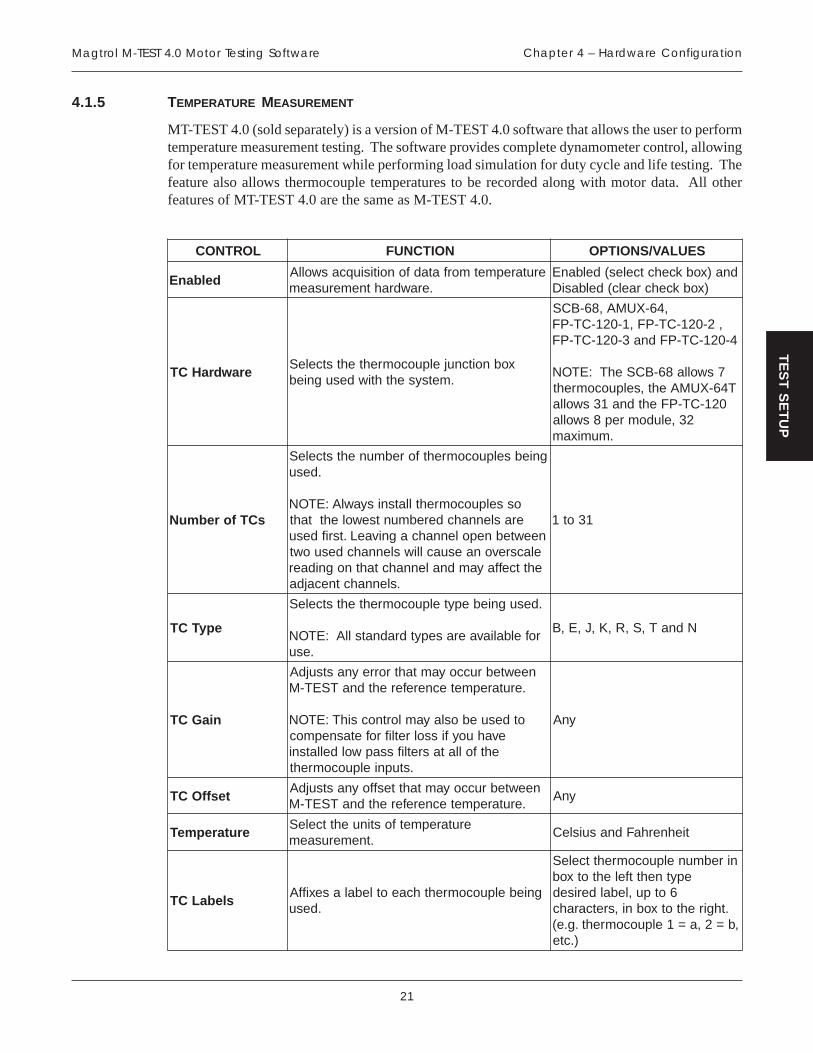
4.1.5 TEMPERATURE MEASUREMENT
MT-TEST 4.0 (sold separately) is a version of M-TEST 4.0 software that allows the user to performtemperature measurement testing. The software provides complete dynamometer control, allowingfor temperature measurement while performing load simulation for duty cycle and life testing. Thefeature also allows thermocouple temperatures to be recorded along with motor data. All otherfeatures of MT-TEST 4.0 are the same as M-TEST 4.0.
LORTNOC NOITCNUF SEULAV/SNOITPO
delbanEerutarepmetmorfatadfonoitisiuqcaswollA
.erawdrahtnemerusaemdna)xobkcehctceles(delbanE
)xobkcehcraelc(delbasiD
erawdraHCTxobnoitcnujelpuocomrehtehtstceleS
.metsysehthtiwdesugnieb
,46-XUMA,86-BCS,2-021-CT-PF,1-021-CT-PF
4-021-CT-PFdna3-021-CT-PF
7swolla86-BCSehT:ETONT46-XUMAeht,selpuocomreht
021-CT-PFehtdna13swolla23,eludomrep8swolla
.mumixam
sCTforebmuN
gniebselpuocomrehtforebmunehtstceleS.desu
osselpuocomrehtllatsnisyawlA:ETONeraslennahcderebmuntsewolehttaht
neewtebnepolennahcagnivaeL.tsrifdesuelacsrevonaesuaclliwslennahcdesuowtehttceffayamdnalennahctahtnognidaer
.slennahctnecajda
13ot1
epyTCT
.desugniebepytelpuocomrehtehtstceleS
rofelbaliavaerasepytdradnatsllA:ETON.esu
NdnaT,S,R,K,J,E,B
niaGCT
neewtebruccoyamtahtrorreynastsujdA.erutarepmetecnereferehtdnaTSET-M
otdesueboslayamlortnocsihT:ETONevahuoyfissolretlifrofetasnepmoc
ehtfollatasretlifssapwoldellatsni.stupnielpuocomreht
ynA
tesffOCTneewtebruccoyamtahttesffoynastsujdA
.erutarepmetecnereferehtdnaTSET-MynA
erutarepmeTerutarepmetfostinuehttceleS
.tnemerusaemtiehnerhaFdnasuisleC
slebaLCTgniebelpuocomrehthcaeotlebalasexiffA
.desu
nirebmunelpuocomrehttceleSepytnehttfelehtotxob
6otpu,lebalderised.thgirehtotxobni,sretcarahc
,b=2,a=1elpuocomreht.g.e().cte
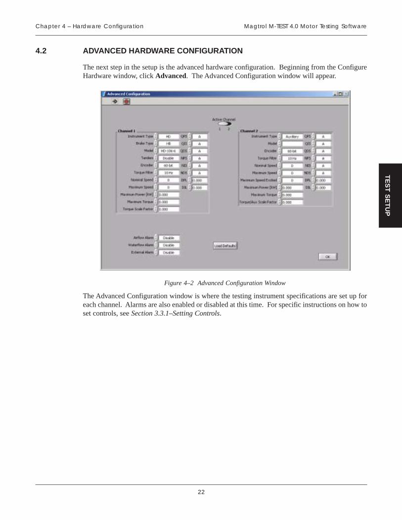
22
Magtrol M-TEST 4.0 Motor Testing SoftwareChapter 4 – Hardware Configuration
TE
ST
SE
TU
P
4.2 ADVANCED HARDWARE CONFIGURATION
The next step in the setup is the advanced hardware configuration. Beginning from the ConfigureHardware window, click Advanced. The Advanced Configuration window will appear.
Figure 4–2 Advanced Configuration Window
The Advanced Configuration window is where the testing instrument specifications are set up foreach channel. Alarms are also enabled or disabled at this time. For specific instructions on how toset controls, see Section 3.3.1–Setting Controls.
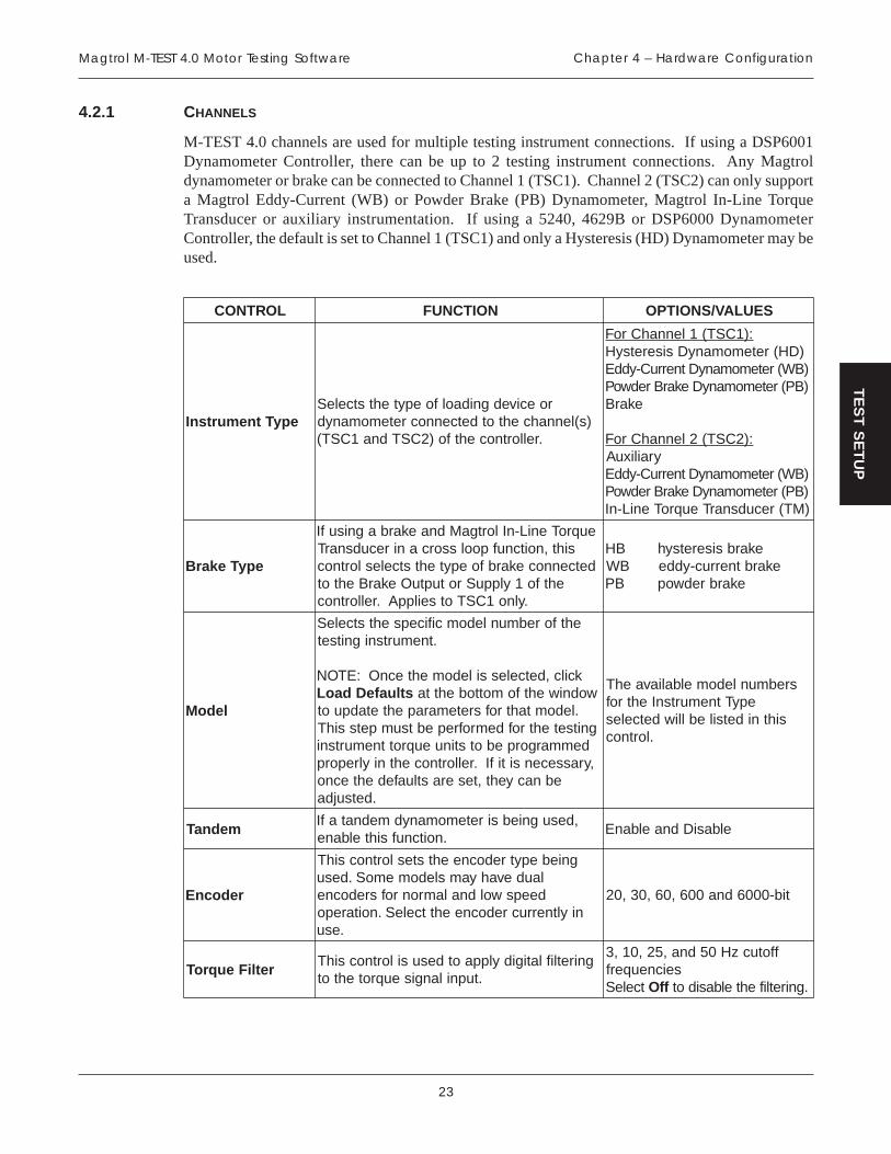
23
Magtrol M-TEST 4.0 Motor Testing Software Chapter 4 – Hardware Configuration
TE
ST
SE
TU
P
4.2.1 CHANNELS
M-TEST 4.0 channels are used for multiple testing instrument connections. If using a DSP6001Dynamometer Controller, there can be up to 2 testing instrument connections. Any Magtroldynamometer or brake can be connected to Channel 1 (TSC1). Channel 2 (TSC2) can only supporta Magtrol Eddy-Current (WB) or Powder Brake (PB) Dynamometer, Magtrol In-Line TorqueTransducer or auxiliary instrumentation. If using a 5240, 4629B or DSP6000 DynamometerController, the default is set to Channel 1 (TSC1) and only a Hysteresis (HD) Dynamometer may beused.
LORTNOC NOITCNUF SEULAV/SNOITPO
epyTtnemurtsnIroecivedgnidaolfoepytehtstceleS
)s(lennahcehtotdetcennocretemomanyd.rellortnocehtfo)2CSTdna1CST(
:)1CST(1lennahCroF)DH(retemomanyDsiseretsyH)BW(retemomanyDtnerruC-yddE)BP(retemomanyDekarBredwoP
ekarB
:)2CST(2lennahCroFyrailixuA
)BW(retemomanyDtnerruC-yddE)BP(retemomanyDekarBredwoP)MT(recudsnarTeuqroTeniL-nI
epyTekarB
euqroTeniL-nIlortgaMdnaekarbagnisufIsiht,noitcnufpoolssorcanirecudsnarT
detcennocekarbfoepytehtstceleslortnocehtfo1ylppuSrotuptuOekarBehtot
.ylno1CSTotseilppA.rellortnoc
ekarbsiseretsyhBHekarbtnerruc-yddeBW
ekarbredwopBP
ledoM
ehtforebmunledomcificepsehtstceleS.tnemurtsnignitset
kcilc,detcelessiledomehtecnO:ETONstluafeDdaoL wodniwehtfomottobehtta
.ledomtahtrofsretemarapehtetadpuotgnitsetehtrofdemrofrepebtsumpetssihT
demmargorpebotstinueuqrottnemurtsni,yrassecensitifI.rellortnocehtniylreporp
ebnacyeht,teserastluafedehtecno.detsujda
srebmunledomelbaliavaehTepyTtnemurtsnIehtrof
sihtnidetsileblliwdetceles.lortnoc
mednaT,desugniebsiretemomanydmednatafI
.noitcnufsihtelbaneelbasiDdnaelbanE
redocnE
gniebepytredocneehtsteslortnocsihTlaudevahyamsledomemoS.desudeepswoldnalamronrofsredocne
niyltnerrucredocneehttceleS.noitarepo.esu
tib-0006dna006,06,03,02
retliFeuqroTgniretliflatigidylppaotdesusilortnocsihT
.tupnilangiseuqrotehtot
ffotuczH05dna,52,01,3seicneuqerf
tceleS ffO .gniretlifehtelbasidot
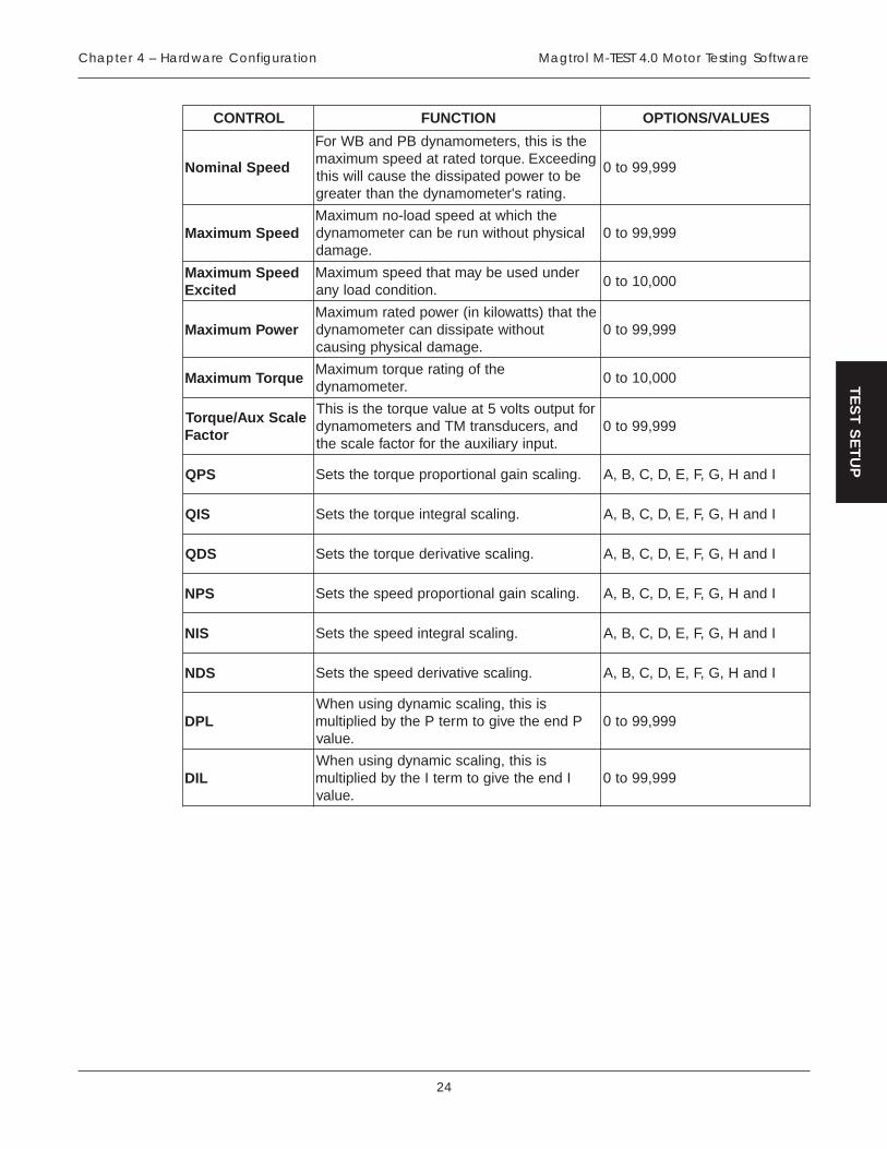
24
Magtrol M-TEST 4.0 Motor Testing SoftwareChapter 4 – Hardware Configuration
TE
ST
SE
TU
P
LORTNOC NOITCNUF SEULAV/SNOITPO
deepSlanimoN
ehtsisiht,sretemomanydBPdnaBWroFgnideecxE.euqrotdetartadeepsmumixam
ebotrewopdetapissidehtesuaclliwsiht.gnitars'retemomanydehtnahtretaerg
999,99ot0
deepSmumixaMehthcihwtadeepsdaol-onmumixaM
lacisyhptuohtiwnurebnacretemomanyd.egamad
999,99ot0
deepSmumixaMdeticxE
rednudesuebyamtahtdeepsmumixaM.noitidnocdaolyna
000,01ot0
rewoPmumixaMehttaht)sttawolikni(rewopdetarmumixaM
tuohtiwetapissidnacretemomanyd.egamadlacisyhpgnisuac
999,99ot0
euqroTmumixaMehtfognitareuqrotmumixaM
.retemomanyd000,01ot0
elacSxuA/euqroTrotcaF
roftuptuostlov5taeulaveuqrotehtsisihTdna,srecudsnartMTdnasretemomanyd
.tupniyrailixuaehtrofrotcafelacseht999,99ot0
SPQ .gnilacsniaglanoitroporpeuqrotehtsteS IdnaH,G,F,E,D,C,B,A
SIQ .gnilacslargetnieuqrotehtsteS IdnaH,G,F,E,D,C,B,A
SDQ .gnilacsevitaviredeuqrotehtsteS IdnaH,G,F,E,D,C,B,A
SPN .gnilacsniaglanoitroporpdeepsehtsteS IdnaH,G,F,E,D,C,B,A
SIN .gnilacslargetnideepsehtsteS IdnaH,G,F,E,D,C,B,A
SDN .gnilacsevitavireddeepsehtsteS IdnaH,G,F,E,D,C,B,A
LPDsisiht,gnilacscimanydgnisunehW
PdneehtevigotmretPehtybdeilpitlum.eulav
999,99ot0
LIDsisiht,gnilacscimanydgnisunehW
IdneehtevigotmretIehtybdeilpitlum.eulav
999,99ot0

25
Magtrol M-TEST 4.0 Motor Testing Software Chapter 4 – Hardware Configuration
TE
ST
SE
TU
P
4.2.2 ALARMS
Only for use with the DSP6001 Dynamometer Controller.
LORTNOC NOITCNUF SEULAV/SNOITPO
wolfriArofnoitcnufmralawolfriaehtselbanE
kcalagnitacidni,sretemomanydsiseretsyh.wolfriafo
elbasiDdnaelbanE
wolfretaW
rofnoitcnufmralawolfretawehtselbanEekarbredwopdnatnerruc-ydde
retawfokcalagnitacidni,sretemomanyd.wolf
elbasiDdnaelbanE
lanretxEynarofnoitcnufmralalanretxeehtselbanE
desabmelborpagnitacidni,retemomanyd.tupniresulanoitiddano
elbasiDdnaelbanE
Note: For more information on Alarms, see Chapter 6 – Alarm System inthe DSP6001 Dynamometer Controller User's Manual.
4.2.3 ACTIVE CHANNEL
• Selects the channel on which the control loop is closed when using a DSP6001.
• Click inside the Active Channel box to select the channel.
Note: Certain load device/dynamometer combinations will not permitchanging channels. See Section 4.2.1–Channels.
4.2.4 LOAD DEFAULTS
• Loads default values for all parameters from the M-TEST Defaults.txt file after a model hasbeen selected.
• Click Load Defaults and the values will automatically update.
Note: This step must be completed for the testing instrument torque unitsto be programmed properly into the controller. If necessary, oncethe defaults are set, they can be adjusted.
4.2.4.1 Updated M-TEST Defaults File
The M-TEST Defaults file is subject to change as ratings on Magtrol’s Motor Test Equipmentchange. If you have purchased any Magtrol Dynamometers or In-Line Torque Transducers sinceinitially installing M-TEST 4.0, visit www.magtrol.com/support/downloads.htm#mtestdefaults onMagtrol’s web site to ensure that you have the most recent M-TEST Defaults.txt file available.Simply click the link to connect you directly or type the web address into your browser. Please feelfree to contact our sales department at 1-716-668-5555, if you should have any questions or concerns.

26
TE
ST
SE
TU
P
5. Selecting a Test
Before any further setup is completed, a test type must be chosen. M-TEST 4.0 offers 4 methods oftesting: ramp, curve, manual and pass/fail. This chapter will provide all the information needed tomake a test selection.
5.1 RAMP TESTING
5.1.1 OLD MEASURING METHODS
Years ago, motor performance was determined by loading a motor to a specific speed and recordingthe torque data. This was repeated at a number of points until sufficient data was acquired to constructa curve. While the method produced accurate data at each point, the time to accomplish this wasexcessive and the motors tended to heat up severely, causing a shift in the data.
5.1.2 NEW MEASURING METHODS
Methods were developed to quickly ramp a motor from free run to locked rotor, negating the heatingeffects. However, along with the ramping came inertial effects on the data.
When a motor is accelerating or decelerating:
Measured Torque = True Motor Torque ± Inertial Torque (stored energy)
Unless inertial torque is excluded, motor performance data will be in error since the measuredtorque will vary in proportion to the rate of acceleration or deceleration. This type of error canproduce startling results. For example, during rapid deceleration, system inertia can produce apparentefficiency greater than 1. This may occur as output power is divided by input power without extractingthe stored energy of the system. M-TEST 4.0 provides two methods of measuring inertiallycompensated data, Average-D/U (Down/Up) and Dynamic-CF.
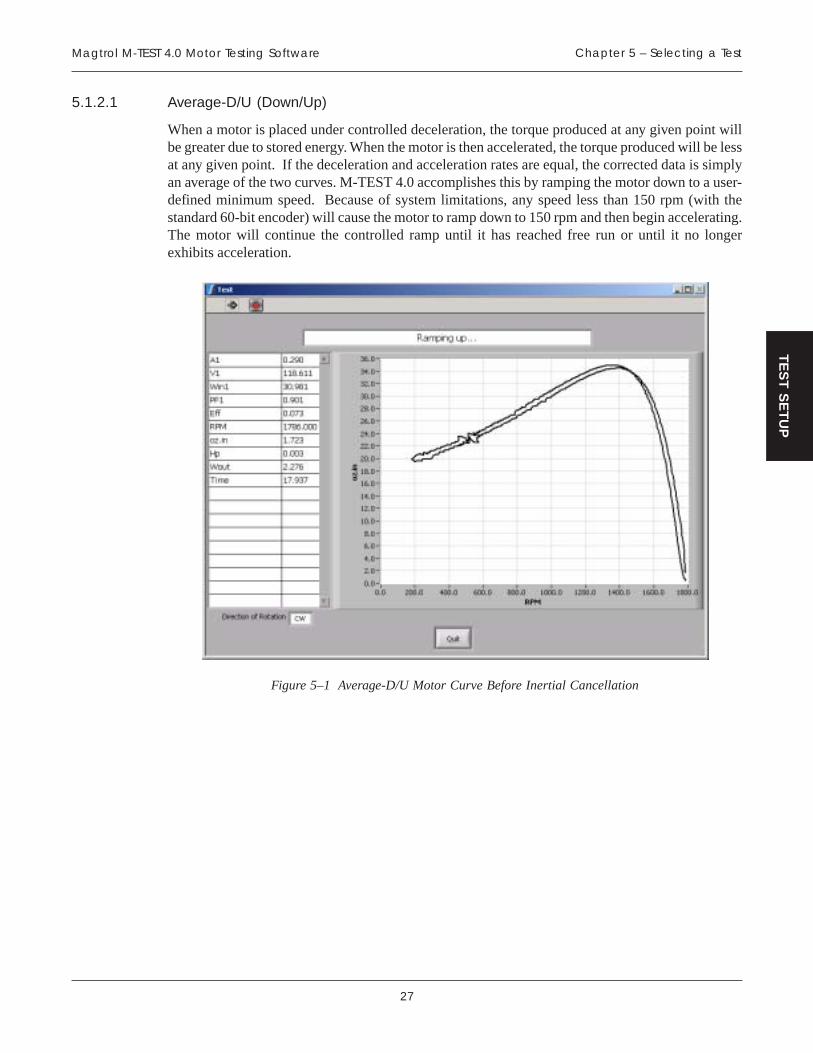
27
Magtrol M-TEST 4.0 Motor Testing Software Chapter 5 – Selecting a Test
TE
ST
SE
TU
P
5.1.2.1 Average-D/U (Down/Up)
When a motor is placed under controlled deceleration, the torque produced at any given point willbe greater due to stored energy. When the motor is then accelerated, the torque produced will be lessat any given point. If the deceleration and acceleration rates are equal, the corrected data is simplyan average of the two curves. M-TEST 4.0 accomplishes this by ramping the motor down to a user-defined minimum speed. Because of system limitations, any speed less than 150 rpm (with thestandard 60-bit encoder) will cause the motor to ramp down to 150 rpm and then begin accelerating.The motor will continue the controlled ramp until it has reached free run or until it no longerexhibits acceleration.
Figure 5–1 Average-D/U Motor Curve Before Inertial Cancellation

28
Magtrol M-TEST 4.0 Motor Testing SoftwareChapter 5 – Selecting A Test
TE
ST
SE
TU
P
If locked rotor is specified as a minimum speed, the controller will run a separate procedureimmediately after the acceleration ramp that will quickly take the motor to stall and record the data.The amount of time to wait at stall before taking data is defined by the Locked Rotor Dwell control,found under Ramp Test Parameters in the Configure Software window. See Section 6.6–Ramp TestParameters. Several seconds at locked rotor may be necessary for the system to stabilize (withstored energy and the load cell acting as a spring, there may be some bounce). After acquiring thelocked rotor data the motor will accelerate to its free run speed.
The inertially corrected curve is produced by matching a speed from the deceleration curve with thesame speed from the acceleration curve and averaging the associated torque data. This continues forevery point on the curve. If no exact matching speed is found on the acceleration curve, the data willbe interpolated to create a match. If requested, the locked rotor point will be added to the end of thedata array to construct the complete curve.
Figure 5–2 Average-D/U Motor Curve

29
Magtrol M-TEST 4.0 Motor Testing Software Chapter 5 – Selecting a Test
TE
ST
SE
TU
P
5.1.2.2 Dynamic-CF
Since "inertial effect" is only a factor as speed is changing, and inertial torque is proportional to therate of change, inertial value may be expressed as a unit of torque per change in rpm in a givenperiod of time. The DSP6000 and 6001 accumulate data at intervals of approximately 10 milliseconds.With data rates this fast, the amount of speed change from reading to reading is too small to be usedaccurately in the correction. Therefore, M-TEST 4.0 inserts a wait state of 100 ms between eachreading in order to allow a reasonable speed change.
In order to create a torque correction factor (CF), a torque value equal to the inertial torque and thedifference in rpm (per 100 ms) that created that value is needed. In the following example, we havedecelerated the motor from free run (FR) to some minimum speed value. A speed equal toapproximately 75% of FR is selected from the curve. One speed point either side of that point isused to obtain an average speed change that produces that torque. That value is now programmed asa static speed point. We now have data from the deceleration curve at 75% of FR and data from astatic point at 75% of FR. The difference in torque divided by the change in speed produces thetorque correction factor.
DYNAMICTORQUE VALUE
STATICTORQUE VALUE
AVERAGE THE CHANGEIN SPEED BETWEEN
THESE POINTS
TORQUE
SP
EE
D
CF = DIFFERENCE IN TORQUECHANGE IN SPEED
DIFFERENCEIN TORQUE
DECELERATION SPEEDvs. TORQUE CURVE
FR
0
}0.75 OF FR
Figure 5–3 Correction Factor Calculation

30
Magtrol M-TEST 4.0 Motor Testing SoftwareChapter 5 – Selecting A Test
TE
ST
SE
TU
P
The test sequence is to ramp a motor down from its free-run speed to a user-specified minimumspeed or maximum torque. The ramp is then terminated and the motor is allowed to accelerate.When the motor nears free-run speed, it is loaded to a static speed (approximately 75% of free run).When ten readings are acquired within ± 0.3% of the target speed, loading is removed and the motormay be turned off. The correction factor is then calculated.
Figure 5–4 Dynamic-CF Test Before Inertial Cancellation

31
Magtrol M-TEST 4.0 Motor Testing Software Chapter 5 – Selecting a Test
TE
ST
SE
TU
P
The correction can now be applied to the entire deceleration curve. For any point on the curve, thecorrected torque is the measured torque minus the CF value times the speed difference between thispoint and the previous point. Because there is no deceleration at free run and locked rotor, torquecorrection is not applied to these points.
Figure 5–5 Dynamic-CF Test
5.2 CURVE TESTING
M-TEST 4.0 can be used in a way that simulates complex load profiles. This may be for heat run orendurance testing, simulating a real life usage, or just for checking a few specific data points.Loading may be accomplished by closing a control loop on Speed, Torque, or Output Watts, plusAmps or Input Watts if a power analyzer is incorporated into the system. Because closed loop speedand torque are internal functions of the dynamometer controller, the control loops are very fast andhighly controllable. The remaining functions use a routine in M-TEST 4.0 to close the loop andprovide control. These will not provide the tight control as the internal functions but are quitesatisfactory for most applications.

32
Magtrol M-TEST 4.0 Motor Testing SoftwareChapter 5 – Selecting A Test
TE
ST
SE
TU
P
Loading can be accomplished by either stepping or ramping to the desired point. If you wish to stepto a load point, enter a time of “0” (zero) for that point. If you wish to ramp to a load point, enter thenumber of seconds (or minutes, depending on the timebase setting) for the controller to ramp fromthe starting point to the ending point. To remain at a fixed load for a period of time, use the samevalue for "From" and "To". To obtain free-run or locked rotor data use the following values:
retemaraP nuReerF rotoRdekcoL
spmA 0 99999
sttaWtupnI 0 99999
deepS 99999 0
euqroT 0 99999
sttaWtuptuO 0 99999
In the example below we will perform a Torque Curve test that will:1. Ramp the torque from zero to 10 in 5 seconds2. Dwell at 10 for 5 seconds3. Step to 20 in zero seconds4. Dwell at 20 for 5 seconds5. Ramp to zero in 3 seconds6. Dwell at zero for 5 seconds7. Repeat the cycle a second time.
Figure 5–6 Torque Curve Setup Example

33
Magtrol M-TEST 4.0 Motor Testing Software Chapter 5 – Selecting a Test
TE
ST
SE
TU
P
Figure 5–7 Torque Curve Test Example
5.3 MANUAL TESTING
In this mode of operation, the computer is being used only as a data acquisition device. No controlis performed by M-TEST 4.0.
5.4 PASS/FAIL TESTING
Pass/Fail motor testing provides production line testing of motors at specified load points, testspecification comparisons and a quick pass or fail indication to the operator. Up to five parameterscan be tested simultaneously and checked against values entered by the user. Testing at free run andlocked rotor can also be performed. The user determines the length of time to hold at each particularload point. Test runs and their associated data may be stored in any user defined directory (passedmotor data in one, failed motor data in a separate directory) for future reference. This data caneasily be exported to a Microsoft® Excel spreadsheet.
Loading can be accomplished by either stepping or ramping to the desired point. If you wish to stepto a load point, enter a time of "0" (zero) for that point. If you wish to ramp to a load point, enter thenumber of seconds (or minutes, depending on the timebase setting) for the controller to ramp fromthe starting point to the ending point. To remain at a fixed load for a period of time, use the samevalue for "From" and "To". To obtain free-run or locked rotor data use the following values:
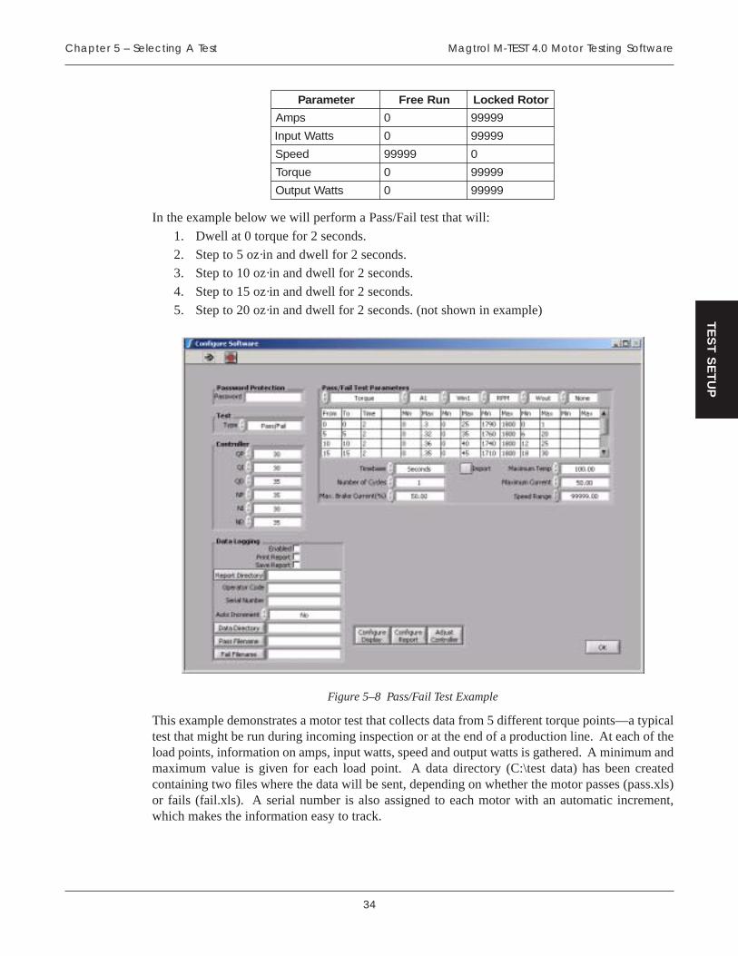
34
Magtrol M-TEST 4.0 Motor Testing SoftwareChapter 5 – Selecting A Test
TE
ST
SE
TU
P
retemaraP nuReerF rotoRdekcoL
spmA 0 99999
sttaWtupnI 0 99999
deepS 99999 0
euqroT 0 99999
sttaWtuptuO 0 99999
In the example below we will perform a Pass/Fail test that will:
1. Dwell at 0 torque for 2 seconds.
2. Step to 5 oz·in and dwell for 2 seconds.3. Step to 10 oz·in and dwell for 2 seconds.
4. Step to 15 oz·in and dwell for 2 seconds.
5. Step to 20 oz·in and dwell for 2 seconds. (not shown in example)
Figure 5–8 Pass/Fail Test Example
This example demonstrates a motor test that collects data from 5 different torque points—a typicaltest that might be run during incoming inspection or at the end of a production line. At each of theload points, information on amps, input watts, speed and output watts is gathered. A minimum andmaximum value is given for each load point. A data directory (C:\test data) has been createdcontaining two files where the data will be sent, depending on whether the motor passes (pass.xls)or fails (fail.xls). A serial number is also assigned to each motor with an automatic increment,which makes the information easy to track.

35
Magtrol M-TEST 4.0 Motor Testing Software Chapter 5 – Selecting a Test
TE
ST
SE
TU
P
When the test is running, the data will appear as follows.
Figure 5–9 Pass/Fail Test Run Window
Once the test is completed, a window will appear that indicates the results of the test.
Figure 5–10 Pass/Fail Test Results Window

36
Magtrol M-TEST 4.0 Motor Testing SoftwareChapter 5 – Selecting A Test
TE
ST
SE
TU
P
In this example all parameters passed the test as indicated by the green PASS bar in the upperportion of the window. In the event that at least one parameter fails, a red FAIL bar will appear inthe window and the parameter that fails will be indicated with an asterisk (*) on either side of thevalue as demonstrated in the following example.
Figure 5–11 Failed Test Example

37
Magtrol M-TEST 4.0 Motor Testing Software Chapter 5 – Selecting a Test
TE
ST
SE
TU
P
The data from the passed test will be sent to the pass.xls file that was set up at the beginning of thetest.
Figure 5–12 Microsoft Excel Data File
The data file contains the date and time of the test run, the serial number of the motor and the datathat was collected during the test. The order in which the data is displayed from left to right isdetermined by the order of parameter selection in the Configure Display window during initialsetup. See Section 6.7–Configure Display.

38
TE
ST
SE
TU
P
6. Software Configuration
Once the hardware configuration is complete and the testing options have been reviewed, the softwaremust be configured. Beginning from the Main window, click Configure Software. The ConfigureSoftware window will appear.
Figure 6–1 Configure Software Window
The Configure Software window is where the software is programmed for the type of test to beperformed. For specific instructions on how to set controls, see Section 3.3.1–Setting Controls.
6.1 PASSWORD PROTECTION
Optional to the user is the Password Protection feature. This feature is used to secure the configurationfrom any unauthorized tampering. To enable, click inside the Password box and type the desiredpassword.
Note: The Password Protection feature will only protect a specificconfiguration that has been saved. It will not prevent starting M-TEST 4.0 to set up a new program.

39
Magtrol M-TEST 4.0 Motor Testing Software Chapter 6 – Software Configuration
TE
ST
SE
TU
P
6.2 TEST
• Selects the type of test you wish to perform.
• Options include Ramp, Curve, Manual and Pass/Fail tests.
As different tests are selected, the required controls for that test will become active.
Note: For detailed information on Ramp, Curve and Manual testing, seeChapter 5 – Selecting a Test.
6.3 CONTROLLER
LORTNOC NOITCNUF SEULAV/SNOITPO
PQotgnittesniaglanoitroporpeuqrotehtsteS
.rellortnocehtottneseb99ot0
IQeuqrotehtsteS largetni ottnesebotgnittes
.rellortnoceht99ot0
DQtnesebotgnittesevitaviredeuqrotehtsteS
.rellortnocehtot99ot0
PNotgnittesniaglanoitroporpdeepsehtsteS
.rellortnocehtottneseb99ot0
INottnesebotgnitteslargetnideepsehtsteS
.rellortnoceht99ot0
DNtnesebotgnittesevitavireddeepsehtsteS
.rellortnocehtot99ot0

40
Magtrol M-TEST 4.0 Motor Testing SoftwareChapter 6 – Software Configuration
TE
ST
SE
TU
P
6.4 DATA LOGGING
Data Logging allows M-TEST 4.0 to automatically store acquired data at the end of each test. A filename will be created under the path that you have entered using the serial number with a MicrosoftExcel (.xls) extension.
LORTNOC NOITCNUF SEULAV/SNOITPO
delbanE .noitcnufgniggolatadselbanEdna)xobkcehctceles(delbanE
)xobkcehcraelc(delbasiD
tropeRtnirP
retfatroperdetnirpmotsucasetareneG.tsethcae
.tsrifderugifnocebtsumtroperehT:ETONehtkcilC tropeRerugifnoC ehttanottub
.wodniwerawtfoSerugifnoCfomottob
dna)xobkcehctceles(delbanE)xobkcehcraelc(delbasiD
tropeRevaS .tsethcaeretfatropermotsucasevaS
dna)xobkcehctceles(delbanE)xobkcehcraelc(delbasiD
ebtsumtroperehT:ETONnottubehtgnisutsrifderugifnoc
.neercsehtfomottobehttaehtnidevaseblliwtroperehT
ehtnideretneemanelif/htapnacdna,dleifyrotceriDtropeRdetnirpdnadeweiv,dellacereb
erastropeR.emitretalatatpr.ahtiwdevasyllacitamotuaotyrassecensisihT.noisnetxetsetmorftroperaetaitnereffid
ehtotnignillacernehwatad.margorp
yrotceriDtropeRagnitcelesrofxobgolaidelifehtsesseccA
.egarotstroperrofyrotceriddnaevirdynA
edoCrotarepOerehslaitiniroemans'rotarepoehtretnE
.mroftroperehtnotuognitnirprofynA
rebmuNlaireS
gniebrotomehtrofrebmunlairesaretnEehtnognitnirprofdesueblliwsihT.detset
atadfinoitarenegemanelifdnatroper.delbanesigniggol
ynA
tnemercnIotuA
ehttnemercnilliwerutaefsihtgnilbanEhcaefodneehttaenoybrebmunlaires
fomrofehtnisirebmunlairesehtfI.tsetskoolmargorpeht,gnirtsciremunahplanafI.gnirtsehtniretcarahcahplatsalehtrof
eblliwrebmuntaht,tiswollofrebmuna.tsetehtfodneehttaenoybdetnemercni
ahplatsalehtswollofrebmunonfIdnadeddaeblliwrebmuna,retcarahc
.tsethcaeretfadetnemercni
oNdnaseY

41
Magtrol M-TEST 4.0 Motor Testing Software Chapter 6 – Software Configuration
TE
ST
SE
TU
P
LORTNOC NOITCNUF SEULAV/SNOITPO
yrotceriDataD
atadrofyrotceriddnaevirdehtseificepS,stsetlaunamropmar,evrucroF.gniggol
detarenegyllacitamotuasiemanelifeht.rebmunlairesehtmorf
rofxobgolaidelifehtsseccaoT:ETONatadrofyrotceriddnaevirdagnitceles
.nottubyrotceriDataDehtkcilc,egarots
A/N
emaneliFssaP
emanelifdnayrotcerid,evirdehtseificepSylnodesusisihT.gniggolatadssaProf
ehT.gnitsetrotomliaF/ssaPgnirudemit,etadehtfotsisnoclliwelifdetarenegehtdna,wortsrifehtnirebmunlairesdna
.)s(worgniwollofehtniatadworaevahlliwtniopkcehcliaF/ssaPhcaEdedroceratadlautcaehtsihcihw,atadfo
ehteblliwelifehtniatadehT.tnioptahttaehtnidetceleserewtahtsretemarap
niredroehT.enituor"yalpsiDerugifnoC"emasehtnieblliwraeppayehthcihw
noitcelesehtniraeppayehtsaecneuqeselifemasehtgnisustsetlanoitiddA.xob
ehtotdedneppaatadriehtevahlliweman.elif
rofxobgolaidelifehtsseccaoT:ETONemanelifdnayrotcerid,evirdagnitceles
ssaPehtkcilc,gniggolatadssaProf.nottubemaneliF
ynA
emaneliFliaF
emanelifdnayrotcerid,evirdehtseificepSylnodesusisihT.gniggolatadliaFrof
ehT.gnitsetrotomliaF/ssaPgnirudemit,etadehtfotsisnoclliwelifdetarenegehtdna,wortsrifehtnirebmunlairesdna
.)s(worgniwollofehtniatadworaevahlliwtniopkcehcliaF/ssaPhcaEdedroceratadlautcaehtsihcihw,atadfo
ehteblliwelifehtniatadehT.tnioptahttaehtnidetceleserewtahtsretemarap
niredroehT.enituor"yalpsiDerugifnoC"emasehtnieblliwraeppayehthcihw
noitcelesehtniraeppayehtsaecneuqeselifemasehtgnisustsetlanoitiddA.xob
ehtotdedneppaatadriehtevahlliweman.elif
rofxobgolaidelifehtsseccaoT:ETONemanelifdnayrotcerid,evirdagnitceles
emaneliFliaFehtkcilc,gniggolatadliaFrof.nottub
ynA

42
Magtrol M-TEST 4.0 Motor Testing SoftwareChapter 6 – Software Configuration
TE
ST
SE
TU
P
6.5 CURVE/MANUAL TEST PARAMETERS
When a Curve Test has been selected as the Test Type, the window will appear as follows.
Figure 6–2 Curve Test Setup Window
When a Manual Test has been selected as the Test Type, the window will appear as follows.
Figure 6–3 Manual Test Setup Window

43
Magtrol M-TEST 4.0 Motor Testing Software Chapter 6 – Software Configuration
TE
ST
SE
TU
P
The following parameters may be used when running a Curve or Manual Test.
LORTNOC NOITCNUF SEULAV/SNOITPO
tropmI
namorfelbatlaunam/evrucrofatadstropmI.eliftxetdetimiled-batlanretxe
esoohcdnaxobgolaidelifehtsseccaoT:ETON.nottubtropmIehtkcilc,elifetairporppaeht
A/N
lortnoCretemaraP
sadesuebotretemarapderisedehtstceleS.lortnoceht
,euqroTrodeepSybgnillortnocnehW:ETONesolcotyrtiucriclanretnistisesurellortnoceht
DIPehT.tnioptesderisedehtnopoolehtesnopsermetsysrofevitcaylluferaslortnoc
tupnI,spmAgnisunehw,revewoH.gninutrellortnoceht,lortnocsttaWtuptuOro,sttaW
sipoolehtdnaedompoolneponanisetareposihT.margorp0.4TSET-Mehthguorhtdesolcebtonylbaborplliwpoollortnocehttahtsnaem
ehT.sedomeuqroTrodeepSehtsathgitsasielbaliavalortnocgninutmetsysylno
.niaglanoitroporp
,3spmA,2spmA,1spmAtupnI,1sttaWtupnI,muSspmA
tupnI,3sttaWtupnI,2sttaW,euqroT,deepS,muSsttaW
.pooLnepOdnasttaWtuptuO
stinuehtnieblliweuqroT:ETONyalpsiDehtnidetcelesylsuoiverp"rellortnoC"rednulortnoceuqroT
erawdraHerugifnoCehtnitupnIdnaspmAroF.wodniw
otsreferrebmuneht,lortnocsttaWesahp-eerhtafoesahpeht
esahp-elgnisagnisufI.metsys."1"ahtiwnoitponatceles,ecruos
egnaRdeepS
retemomanydehtrofegnardeepsehtsteS.rellortnoc
ylthgilsebdluohsderetneeulavehT:ETON.rotomehtfodeepsnureerfehtnahtretaergeviglliwylreporpegnaRdeepSehtgnitsujdA.sgnittesDIPehtrofegnarcimanydtsebeht
mednatahtiwdesuylnosiretemarapsihT.putesretemomanyd
999,99ot0
esabemiT ehtniseulavemitehtllarofesabemitehtsteS.elbatlortnoc setuniMdnasdnoceS
gnilpmaS)ces(etaR
lliwtniopatadahcihwtalavretniemitehtsteS.derotsdnadelpmaseb
demitdnatseTlaunaMehtgnisunehW:ETONtayllacitamotuaderotseblliwatadeht,egarots
001sietartsetsafehT.erehdetcelesetareht.)s10.0(dnocesrepselpmas
ynA
etartsetsafehT:ETON01sitseTevruCanidewolla.)s01.0(dnocesrepselpmasredroniyrassecensietarsihTrofgnimitetaruccaniatniamot
.sretemarapllewddnapmarehtylnoataderiuqcaothsiwuoyfI,doirepllewdhcaefodneehtta
."99999"epyt
forebmuNselcyC
daolehttaeperotsemitforebmunehtstceleS.elcyc 76723ot1
ekarB.xaMtnerruC
tnereffideriuqersretemomanydezistnereffiD,euqrotllufecudorpottnerrucCDfostnuoma
rotomaforotorehtkcoloteuqrothguoneros'retemomanydsiseretsyhehT.detsetgnieb
sitnerrucfidezitengamemoceblliwrotorsihT.gninruttonsitfahsehtelihwdeilppa
asanwonkosla,msitengamlaudisersecudorppmubeht,deilppasitnerruchcumootfI.pmub
ehtwollatonotsaegralyltneiciffusebyamlortnocsihT.niagagnitatornigebotrotom
fotnuomamuminimehttesotdesuebdluohsfirotorehtkcolllitslliwtahtyrassecentnerruc
.ecneuqestsetehtgnirudderised
siht,derisedtonsirotordekcolfI:ETON.tnavelerrisilortnoc
%99.99ot0

44
Magtrol M-TEST 4.0 Motor Testing SoftwareChapter 6 – Software Configuration
TE
ST
SE
TU
P
LORTNOC NOITCNUF SEULAV/SNOITPO
mumixaMpmeT
erutarepmetrofteseboteulavmumixamaswollA.erawdrahnoitisiuqcaerutarepmetgnisunehw
ehtsdeecxeelpuocomrehtynafI:ETONnitseteht,eulaverutarepmeTmumixaM
.troballiwssergorp
ynA
ehterastinuerutarepmeT:ETONrednudetcelessawtahwsaemas
ehtnitnemerusaeMerutarepmeT.wodniwerawdraHerugifnoC
mumixaMtnerruC
.tnerrucrofteseboteulavmumixamaswollA
eulavehtsdeecxetnerrucderusaemehtfI:ETON.troballiwssergorpnitseteht,lortnocsihtybputes
ynA
6.5.1 CONTROL DATA
• Used for entering a load profile for curve tests.
• Table includes the following items:
From: The starting load value.
To: The ending load value.
Time: The number of seconds or minutes to achieve the series.
Volts: Sets the voltage for each step when using a DC power supply. The power supplywill be programmed to the voltage desired at the beginning of each step.
Note: Volts are only applicable when using a DC Power Supply and willnot be visible to the user during AC operation.
• To set, type values in the table and use the TAB key or mouse to move from cell to cell. Thetime units are set by the Timebase control to the right and are applied to all time values inthe table. Any values entered in the “From” and “To” columns will be in the units specifiedby the control parameter. To clear the table, right-click inside of it and select Empty Table.
Note: If a certain profile is repetitive, enter the basic sequence in thetable once and use the Number of Cycles control on the right torepeat that sequence any number of times.
The following is an example of using the Control Data while running a torque curve with an ACPower Supply.
ecneuqeS morF oT emiT noitpircseD
1 0 0 2 .sdnoces2rofeuqrotorezhtiwrotomehtdaollliwsihT
2 0 01 01 .sdnoces01nistinueuqrot01ot0morfdaolehtpmarlliwsihT
3 01 01 5 .sdnoces5rofstinueuqrot01tallewdlliwsihT
4 01 0 0 .sdnoces0ni0ot01morfgnippetsybhsiniflliwsihT
Note: When loading by Amps, Input Watts, Torque, or Output Watts, avalue of 0 (zero) will obtain free-run data. A value of 99999 willobtain locked rotor data.
Note: When loading by Speed, a value of 99999 will obtain free-run data.A value of 0 (zero) will obtain locked rotor data.

45
Magtrol M-TEST 4.0 Motor Testing Software Chapter 6 – Software Configuration
TE
ST
SE
TU
P
6.6 RAMP TEST PARAMETERS
When a Ramp Test has been selected as the Test Type, the window will appear as follows.
Figure 6–4 Ramp Test Setup Window

46
Magtrol M-TEST 4.0 Motor Testing SoftwareChapter 6 – Software Configuration
TE
ST
SE
TU
P
The following parameters may be used when running a Ramp Test.
LORTNOC NOITCNUF SEULAV/SNOITPO
aitrenInoitallecnaC
gnirudatadrewopdnaeuqrotetaruccasedivorPgnitatorehtfoygrenederotsehT.tsetpmara
rotomehtekamotsdnetmetsysehtnissamagnirudsiyllautcatinahtregnortskool
sevomernoitallecnacaitrenI.pmarnoitarelecedafisaatadsevigdnatnenopmoclaitrenieht
.nekaterewstniopdezilibatsetercsidforebmun
N doogasiti,secnatsmucrictsomrednU:ETO-cimanyDaecnO.noitallecnacaitreniesuotaedi
,noitallecnacaitrenihtiwnurneebsahtsetFCemasro,rotomemasehtnostsettneuqesbusstneiciffeocehtgnisunurebyamrotomfoepyt
tceleS.nurtsrifehtmorfdeniatbo suoiverPeulaV yllautcatuohtiwstneiciffeocesohtesuot
ehT.enituornoitallecnacaitreniehtgnimrofrepaitrenisahyltnerehnienituorU/D-egarevA
.nursitiemityrevenoitallecnac
otrefer,noitamrofnieromroF 1.5noitceSgnitseTpmaR– .
eulaVsuoiverPdnaoN,seY
dohteMpmaRehttsetotdesudohtempmarehtstceleS
.rotom
U/D-egarevA foegarevanA:dnanoitarelecedeht
yllacipyT.sevrucnoitareleccaetaruccatsomehtsecudorp
tahwemossidnastluserrellortnocehtnotnedneped
aitrenI.gninutpmar.citamotuasinoitallecnac
FC-cimanyD : senimreteDnodesabrotcafnoitcerroc
dnaevrucnoitarelecednoitcerrocehT.tniopdezilibats
ehtotdeilppanehtsirotcafsihtrofredronI.tesataderitne
metsyseht,ylreporpkrowot.lacitircylhgihsigninut
etaRpmaRmprnipmarehtfoetarnoitarelecedehtsteS
.dnocesrepynA
mumixaMdeepS
pmarehtfotratsrotimilreppuehtsteS
ehterehwsesacnilufplehebyamsihT:ETONylbissop,deepshgihyrevatasnipsrotomA.rofdetarsiretemomanydehtnahtretsaf
ehtottnessidnammocdezilibatsdeepserofebeulavsihttarotomehtdlohotrellortnoc,ylreporpnoitcnufotredronI.snigebpmarehtroeulavelbanosaeraottesebtsums'DIPeht
.ruccolliwgnidaolon
000,001ot0

47
Magtrol M-TEST 4.0 Motor Testing Software Chapter 6 – Software Configuration
TE
ST
SE
TU
P
LORTNOC NOITCNUF SEULAV/SNOITPO
muminiMdeepS
.pmarehtfotimilrewolehtsteS
ynA
ebnac)0(oreZ:ETON,rotordekcolotnurotdeificeps
ehT.tahtevobadeepsynarotahthcussiesnopsermetsysnoitarepodellortnocyletarucca
simpr001–1foegnarehtnifoesuehttuohtiwelbissopton
.redocnedeepslanoitponaseodlortgaM,nosaertahtroF
niatbootgniyrtdnemmocerton.sdeepsesohttaatad
mumixaMeuqroT
sahtimileuqrotcificepsanehwpmarehtspotS.dehcaerneeb
ynA
ehtnieblliweuqroT:ETONehtnidetcelesylsuoiverpstinu
rednulortnoceuqroTyalpsiDerugifnoCehtnirellortnoC
.wodniwerawdraH
rotoRdekcoL)ces(llewD
a,tsetpmarU/D-egarevAehtgninnurnehW)rotordekcol(orezfognittesdeepSmuminiMatallatsotdedaolebotrotomehtesuaclliwdeificepssawtahwnahtretaergsemitnetetar
ehtniecnuobaesuacyamsihT.tsetehtrofgnitiawybdevomerebtsumtahtgnidaereuqrottesotlortnocsihttsujdA.emitfodoireptrohsa
.gnidaeragnikaterofebemitgniltteseht
ynA
ekarB.xaMtnerruC
tnereffideriuqersretemomanydezistnereffiD,euqrotllufecudorpottnerrucCDfostnuoma
rotomaforotorehtkcoloteuqrothguoneros'retemomanydsiseretsyhehT.detsetgnieb
sitnerrucfidezitengamemoceblliwrotorsihT.gninruttonsitfahsehtelihwdeilppa
asanwonkosla,msitengamlaudisersecudorppmubeht,deilppasitnerruchcumootfI.pmub
ehtwollatonotsaegralyltneiciffusebyamlortnocsihT.niagagnitatornigebotrotom
fotnuomamuminimehttesotdesuebdluohsfirotorehtkcolllitslliwtahtyrassecentnerruc
ecneuqestsetehtgnirudderised
lortnocsiht,derisedtonsirotordekcolfI:ETON.tnavelerrisi
%99.99ot0
DIPcimanyDgnilacS
eulavllufmorfseulavDIPehtfognilacsswollAehttaegatnecrepaotpmarehtfotratsehtta
.pmarehtfodnenOdnaffO
tropmI
namorfelbattsetpmarrofatadstropmI.eliftxetdetimiled-batlanretxe
esoohcdnaxobgolaidelifehtsseccaoT:ETON.nottubtropmIehtkcilc,elifetairporppaeht
A/N
ataDlaicepSstnioP
ehttuohguorhtstniopatadcificepsstceleS.rotomehtfoevrucecnamrofrep
gnivaselifdnagnihparg,yalpsidllA:ETON.ylnostniopesehtnodesabeblliwsnoitceles
esuacebdetpurrocebyamenituorgnihpargehT.stnioplaicepsforedrolarutannuehtfo
seYdnaoN
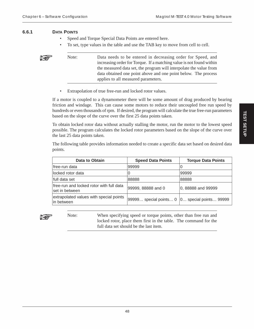
48
Magtrol M-TEST 4.0 Motor Testing SoftwareChapter 6 – Software Configuration
TE
ST
SE
TU
P
6.6.1 DATA POINTS
• Speed and Torque Special Data Points are entered here.
• To set, type values in the table and use the TAB key to move from cell to cell.
Note: Data needs to be entered in decreasing order for Speed, andincreasing order for Torque. If a matching value is not found withinthe measured data set, the program will interpolate the value fromdata obtained one point above and one point below. The processapplies to all measured parameters.
• Extrapolation of true free-run and locked rotor values.
If a motor is coupled to a dynamometer there will be some amount of drag produced by bearingfriction and windage. This can cause some motors to reduce their uncoupled free run speed byhundreds or even thousands of rpm. If desired, the program will calculate the true free-run parametersbased on the slope of the curve over the first 25 data points taken.
To obtain locked rotor data without actually stalling the motor, run the motor to the lowest speedpossible. The program calculates the locked rotor parameters based on the slope of the curve overthe last 25 data points taken.
The following table provides information needed to create a specific data set based on desired datapoints.
niatbOotataD stnioPataDdeepS stnioPataDeuqroT
atadnur-eerf 99999 0
atadrotordekcol 0 99999
tesatadlluf 88888 88888
atadllufhtiwrotordekcoldnanur-eerfneewtebnites
0dna88888,99999 99999dna88888,0
stnioplaicepshtiwseulavdetalopartxeneewtebni
0…stnioplaiceps…99999 99999…stnioplaiceps…0
Note: When specifying speed or torque points, other than free run andlocked rotor, place them first in the table. The command for thefull data set should be the last item.

49
Magtrol M-TEST 4.0 Motor Testing Software Chapter 6 – Software Configuration
TE
ST
SE
TU
P
6.7 PASS/FAIL TEST PARAMETERS
When a Pass/Fail Test has been selected as the Test Type, the window will appear as follows.
Figure 6–5 Pass/Fail Test Setup Window
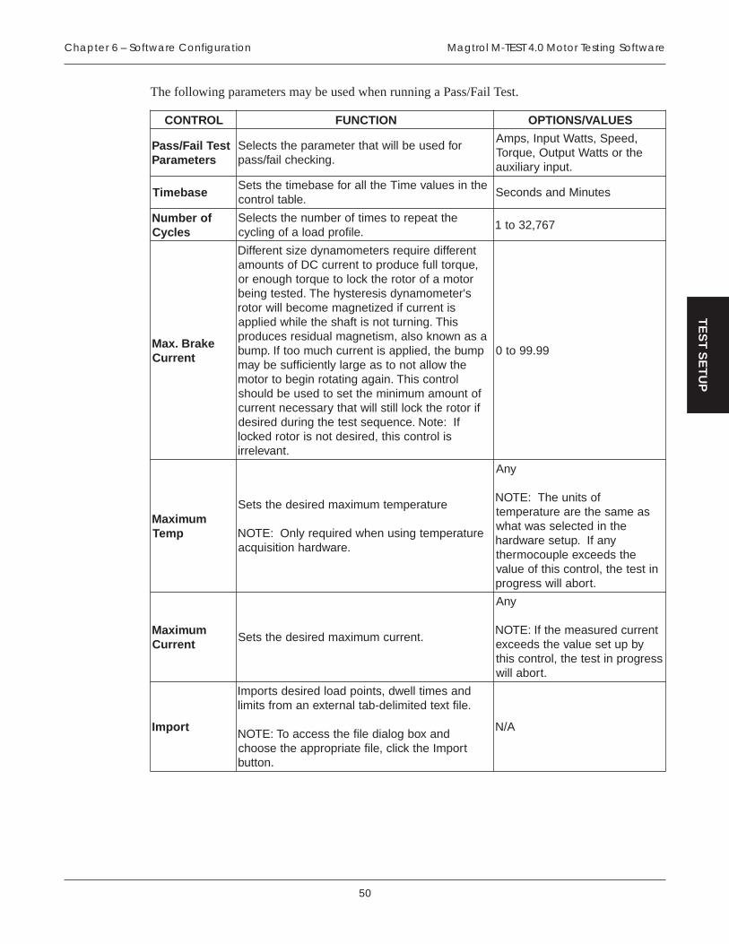
50
Magtrol M-TEST 4.0 Motor Testing SoftwareChapter 6 – Software Configuration
TE
ST
SE
TU
P
The following parameters may be used when running a Pass/Fail Test.
LORTNOC NOITCNUF SEULAV/SNOITPO
tseTliaF/ssaPsretemaraP
rofdesueblliwtahtretemarapehtstceleS.gnikcehcliaf/ssap
,deepS,sttaWtupnI,spmAehtrosttaWtuptuO,euqroT
.tupniyrailixua
esabemiTehtniseulavemiTehtllarofesabemitehtsteS
.elbatlortnocsetuniMdnasdnoceS
forebmuNselcyC
ehttaeperotsemitforebmunehtstceleS.eliforpdaolafognilcyc
767,23ot1
ekarB.xaMtnerruC
tnereffideriuqersretemomanydezistnereffiD,euqrotllufecudorpottnerrucCDfostnuoma
rotomaforotorehtkcoloteuqrothguoneros'retemomanydsiseretsyhehT.detsetgnieb
sitnerrucfidezitengamemoceblliwrotorsihT.gninruttonsitfahsehtelihwdeilppa
asanwonkosla,msitengamlaudisersecudorppmubeht,deilppasitnerruchcumootfI.pmub
ehtwollatonotsaegralyltneiciffusebyamlortnocsihT.niagagnitatornigebotrotom
fotnuomamuminimehttesotdesuebdluohsfirotorehtkcolllitslliwtahtyrassecentnerruc
fI:etoN.ecneuqestsetehtgnirudderisedsilortnocsiht,derisedtonsirotordekcol
.tnavelerri
99.99ot0
mumixaMpmeT
erutarepmetmumixamderisedehtsteS
erutarepmetgnisunehwderiuqerylnO:ETON.erawdrahnoitisiuqca
ynA
fostinuehT:ETONsaemasehteraerutarepmet
ehtnidetcelessawtahwynafI.puteserawdrah
ehtsdeecxeelpuocomrehtnitseteht,lortnocsihtfoeulav
.troballiwssergorp
mumixaMtnerruC
.tnerrucmumixamderisedehtsteS
ynA
tnerrucderusaemehtfI:ETONybputeseulavehtsdeecxe
ssergorpnitseteht,lortnocsiht.troballiw
tropmI
dnasemitllewd,stniopdaolderisedstropmI.eliftxetdetimiled-batlanretxenamorfstimil
dnaxobgolaidelifehtsseccaoT:ETONtropmIehtkcilc,elifetairporppaehtesoohc
.nottub
A/N

51
Magtrol M-TEST 4.0 Motor Testing Software Chapter 6 – Software Configuration
TE
ST
SE
TU
P
6.8 CONFIGURE DISPLAY
From the Configure Software window, click Configure Display. The Configure Display windowwill appear.
Figure 6–6 Configure Display Window
The Configure Display window is where desired parameters to be displayed during the test andshown on the graph are set up. For specific instructions on how to set controls, see Section 3.3.1–Setting Controls.

52
Magtrol M-TEST 4.0 Motor Testing SoftwareChapter 6 – Software Configuration
TE
ST
SE
TU
P
LORTNOC NOITCNUF SEULAV/SNOITPO
sretemaraP
eblliwtahtsretemarapehtstceleSgnirudelbatehtnideyalpsiddnaderusaem
.nurtseta
ehtnognikcilcybmetinatceleS:ETONelpitlumtcelesoT.eciohcforetemarap
elihwyekTFIHSehtnwoddloh,smeti.sretemarapderisedehtnognikcilc
,3spmA,2spmA,1spmA,2stloV,1stloV,muSspmA
sttaWtupnI,muSstloV,3stloV,3sttaWtupnI,2sttaWtupnI,1rotcaFrewoP,muSsttaWtupnI
rewoP,2rotcaFrewoP,1,muSrotcaFrewoP,3rotcaF
stinUeuqroT,deepS,ycneiciffE,rewopesroH,)ni.zo.g.e(
dnaemiT,sttaWtuptuOtupnIyrailixuA
otrefersrebmunehT:ETONesahp-eerhtafoesahpeht
-elgnisagnisufI.metsysnoitponatceles,ecruosesahp
."1"ahtiw
elbisiVhparG
otputesebyamneercsyalpsidtsetehT.tsetehtgnirudhpargemit-laerawohs
noitcnufhpargehtnrutotlortnocsihtesU.fforono
oNdnaseY
sixa-Y-YehtnohpargotretemarapehtstceleS
.tsetehtgnirudsixa
tahtsretemaraPehtfoynAehtmorfdetcelesneebevah
tfelehtottsil
sixa-X
-XehtnohpargotretemarapehtstceleS.tsetehtgnirudsixa
,demrofrepgniebsitsetevrucafI:ETONselpmasehtottluafedlliwsixa-Xeht
.delbasideblliweroferehtdnaderiuqca
tahtsretemaraPehtfoynAehtmorfdetcelesneebevah
tfelehtottsil

53
Magtrol M-TEST 4.0 Motor Testing Software Chapter 6 – Software Configuration
TE
ST
SE
TU
P
6.9 CONFIGURE REPORT
From the Configure Software window, click Configure Report. The Configure Report windowwill appear.
Figure 6–7 Configure Report Window
The Configure Report window is where the desired parameters and overall layout of the customprinted report is selected. For specific instructions on how to set controls, see Section 3.3.1–SettingControls.

54
Magtrol M-TEST 4.0 Motor Testing SoftwareChapter 6 – Software Configuration
TE
ST
SE
TU
P
The following parameters may be used when configuring a report.
LORTNOC NOITCNUF SEULAV/SNOITPO
eltiTtseTfopotehttadecalpeboteltitehtsyalpsiD
.tropereht.eltitderisedepyT
snoitcnuFnodetnirpebotsnoitcnuflaicepsstceleSebnacsnoitcnuftnereffid7otpU.troper
.detceles
,emiTtseT,etaDtseT,enoN,edoCrotarepO,rebmuNlaireS
mumixaM,tnerruCmumixaMmumixaM,ycneiciffE
tupnImumixaM,rewopesroH,sttaWtuptuOmumixaM,sttaW
mumixaM,euqroTmumixaMfonoitceriDdnadeepS
noitatoR
stnemmoCnidedulcniebotstnemmocehtsyalpsiD
.tropereht.stnemmocderisedepyT
hparGwohS .troperehtnohpargswohSwohsotxobkcehcehttceleSotxobkcehcraelc,hpargeht
.tropermorftimo
sixa-Y-YehtnohpargotretemarapehtstceleS
.sixa
sretemaraPehtfoynAehtnidetcelesylsuoiverpwodniwyalpsiDerugifnoC
sixa-X-XehtnohpargotretemarapehtstceleS
.sixa
sretemaraPehtfoynAehtnidetcelesylsuoiverpwodniwyalpsiDerugifnoC
tiFevruC
lacitamehtamasahtolpgnitluserehtfIybdehtoomsebyamepahssti,noitcnuf
lliwmargorpehT.gnittifevrucgnilbaneenituortifevruclaimonyloplarenegaylppa
.atadehttolp-erdnatesatadehtot
hpargehtotseilppatifevrucehT:ETON.atadralubatehttondnaylno
dna)xobkcehctceles(delbanE)xobkcehcraelc(delbasiD
redrOlaimonyloPevrucehtnislaimonylopforedroehtsteS
.enituorgnittif
001ot0
"2"fotluafedehT:ETONtsomroftneiciffusebdluohsdesaercniebyamtub,sevruc
reurtaeveihcaotsitI.noitatneserper
uoytahtdednemmocerneercSehthtiwtnemirepxe
tiftsebehtdnifotenituortolPeulavemasehtesunehtdna
.troperehtrof
hparGYXsretemarapehtgnisutolpelgnisasyalpsiDerasexaehT.sixa-ydnaxehtrofdetceles
.noitulosertsebrofdelacsotua
sretemaraPehtfoynAehtnidetcelesylsuoiverpwodniwyalpsiDerugifnoC
deriseDtceleSsnmuloCataD
atadehtnitnirpotsretemarapstceleS.troperehtfosnmuloc tnereffid9otpU
.detcelesebnacsretemarap
sretemaraPehtfoynAehtnidetcelesylsuoiverpwodniwyalpsiDerugifnoC

55
Magtrol M-TEST 4.0 Motor Testing Software Chapter 6 – Software Configuration
TE
ST
SE
TU
P
6.9.1 SAMPLE REPORT
Following is an example of a customized report generated by M-TEST 4.0
Magtrol, Inc.
40
0
5
10
15
20
25
30
35
20000 500 1000 1500
Test Time:
Serial Number:
Operator Code:
Maximum Efficiency:
Maximum Torque:
Direction of Rotation:
This page displays a typical report that can be generated from M-TEST.
Comments
OzIn
RPM
Test Date:
Speed OzIn Amps 1 Volts 1 Input Watts 1 Power Factor 1 Efficiency Output Watts Horsepower
1795.304 0.000 0.290 119.358 27.245 0.793 0.000 0.000 0.000
1770.000 5.151 0.311 119.235 32.172 0.868 0.210 6.741 0.009
1699.000 18.960 0.383 119.070 43.508 0.954 0.548 23.821 0.032
1648.000 26.276 0.451 118.904 51.474 0.960 0.622 32.022 0.043
1598.000 30.918 0.509 118.775 57.909 0.959 0.631 36.536 0.049
1545.000 33.810 0.558 118.658 63.425 0.957 0.609 38.628 0.052
1500.000 35.310 0.593 118.607 67.254 0.957 0.582 39.167 0.053
1452.000 36.045 0.622 118.573 70.778 0.960 0.547 38.703 0.052
1403.000 36.300 0.649 118.573 72.616 0.944 0.519 37.661 0.051
1358.000 36.157 0.673 118.591 74.454 0.933 0.488 36.310 0.049
1314.000 35.733 0.688 118.517 76.293 0.936 0.455 34.721 0.047
1261.000 35.121 0.712 118.517 78.131 0.927 0.419 32.750 0.044
1213.000 34.316 0.727 118.371 79.969 0.929 0.385 30.782 0.041
1159.000 33.462 0.743 118.389 80.889 0.919 0.355 28.680 0.038
1111.000 32.631 0.757 118.426 81.808 0.912 0.328 26.809 0.036
1069.000 31.924 0.769 118.446 82.727 0.908 0.305 25.236 0.034
1012.000 31.030 0.775 118.573 84.565 0.920 0.275 23.222 0.031
963.000 30.076 0.794 118.573 84.565 0.898 0.253 21.418 0.029
905.000 29.151 0.798 118.610 85.301 0.901 0.229 19.509 0.026
854.000 28.080 0.808 118.609 86.404 0.902 0.205 17.733 0.024
793.000 27.100 0.821 118.573 86.404 0.888 0.184 15.892 0.021
745.000 26.055 0.824 118.371 86.404 0.886 0.166 14.354 0.019
690.000 25.165 0.826 118.316 87.323 0.894 0.147 12.840 0.017
627.000 24.272 0.830 118.371 87.323 0.888 0.129 11.254 0.015
563.000 22.927 0.845 118.426 88.242 0.882 0.108 9.545 0.013
509.000 22.047 0.847 118.371 88.242 0.881 0.094 8.298 0.011
445.000 21.927 0.849 118.334 88.242 0.879 0.082 7.216 0.010
394.000 21.225 0.850 118.352 88.242 0.878 0.070 6.184 0.008
328.000 20.502 0.853 118.444 89.162 0.883 0.056 4.973 0.007
256.000 19.581 0.855 118.426 90.081 0.890 0.041 3.707 0.005
204.000 19.340 0.859 118.426 90.081 0.885 0.032 2.918 0.004
0.000 17.558 0.870 118.379 92.395 0.897 0.000 0.000 0.000
5/8/01
12:18:22 PM
0001
TRW
0.633271
36.330000
CW
Figure 6–8 Sample Motor Test Report

56
Magtrol M-TEST 4.0 Motor Testing SoftwareChapter 6 – Software Configuration
TE
ST
SE
TU
P
6.10 ADJUST CONTROLLER
From the Configure Software window, click Adjust Controller. The Adjust Dynamometer Controllerwindow will appear.
Figure 6–9 Adjust Dynamometer Controller Window
The Adjust Dynamometer Controller window is where PID setup routines are provided. For specificinstructions on how to set controls, see Section 3.3.1–Setting Controls.
In order to assist the operator in adjusting the PID values, there are two setup routines:
(1) Ramp Test Setup Routine: The deceleration curve is shown against an ideal curve andPID's are adjusted until the curves align with each other.
(2) Curve Test Setup Routine: A step function is sent to the controller and the system responseis plotted against it. Adjust PID values on the fly until desired response is obtained.
Adjustments made to the PID values during a Ramp and Curve Test Setup Routine are automaticallytransferred to the Configure Software and Advanced Configuration windows.
Note: When a manual test is being performed, the Adjust DynamometerController window is disabled.
Note: For more detailed information, see Appendix A – PID/Scaling andSection 7.3–Adjusting the Controller.
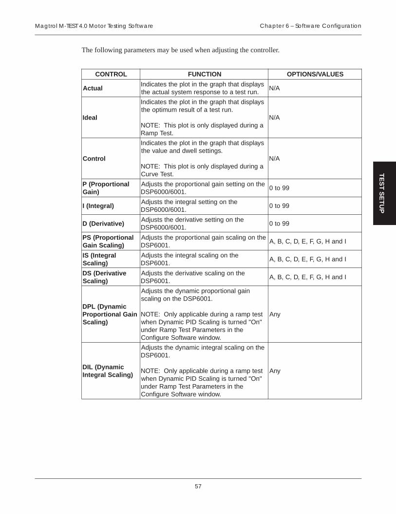
57
Magtrol M-TEST 4.0 Motor Testing Software Chapter 6 – Software Configuration
TE
ST
SE
TU
P
The following parameters may be used when adjusting the controller.
LORTNOC NOITCNUF SEULAV/SNOITPO
lautcAsyalpsidtahthpargehtnitolpehtsetacidnI
.nurtsetaotesnopsermetsyslautcaehtA/N
laedI
syalpsidtahthpargehtnitolpehtsetacidnI.nurtsetafotlusermumitpoeht
agniruddeyalpsidylnositolpsihT:ETON.tseTpmaR
A/N
lortnoC
syalpsidtahthpargehtnitolpehtsetacidnI.sgnittesllewddnaeulaveht
agniruddeyalpsidylnositolpsihT:ETON.tseTevruC
A/N
lanoitroporP(P)niaG
ehtnognittesniaglanoitroporpehtstsujdA.1006/0006PSD
99ot0
)largetnI(IehtnognitteslargetniehtstsujdA
.1006/0006PSD99ot0
)evitavireD(DehtnognittesevitaviredehtstsujdA
.1006/0006PSD99ot0
lanoitroporP(SP)gnilacSniaG
ehtnognilacsniaglanoitroporpehtstsujdA.1006PSD
IdnaH,G,F,E,D,C,B,A
largetnI(SI)gnilacS
ehtnognilacslargetniehtstsujdA.1006PSD
IdnaH,G,F,E,D,C,B,A
evitavireD(SD)gnilacS
ehtnognilacsevitaviredehtstsujdA.1006PSD
IdnaH,G,F,E,D,C,B,A
cimanyD(LPDniaGlanoitroporP
)gnilacS
niaglanoitroporpcimanydehtstsujdA.1006PSDehtnognilacs
:ETON tsetpmaragnirudelbacilppaylnO"nO"denrutsignilacSDIPcimanyDnehw
ehtnisretemaraPtseTpmaRrednu.wodniwerawtfoSerugifnoC
ynA
cimanyD(LID)gnilacSlargetnI
ehtnognilacslargetnicimanydehtstsujdA.1006PSD
tsetpmaragnirudelbacilppaylnO:ETON"nO"denrutsignilacSDIPcimanyDnehw
ehtnisretemaraPtseTpmaRrednu.wodniwerawtfoSerugifnoC
ynA

58
Magtrol M-TEST 4.0 Motor Testing SoftwareChapter 6 – Software Configuration
TE
ST
SE
TU
P
LORTNOC NOITCNUF SEULAV/SNOITPO
eulaVhgiH
derisedehtrofeulavmumixamehtsteSmargorpehT.tnemtsujdaesnospermetsys
sihtdnaeulavwolehtneewtebelcyclliw.eulav
ynA
eulaVwoL
derisedehtrofeulavmuminimehtsteS.tnemtsujdaesnospermetsys margorpehT
hgihehtdnaeulavsihtneewtebelcyclliw.eulav
ynA
llewD
ehtsteslortnocsiht,stsetevrucgnisunehWehtrofdaoltadnadaol-ontaemitllewd
nisiemitehT.erudecorptnemtsujda.sdnoces
767,23ot0
nuR
kcilc,derugifnoceraslortnocehtnehWnuR .erudecorptnemtsujdaehtnigebot
ehtfotnemsujdawollastsetevruC:ETONnurlliwtsetpmarehT.ylfehtnoseulavDIP
ebyamsgnittesehtnehtdna,ecno.niaganurtsetehtdnadegnahc
A/N
tiuQ/potS
tnemtsujdaehtpotsotnottubpotSehtkcilC.tiuQsemocebnottubpotSehT.enituor
tnemtsujdaehttixeotnottubtiuQehtkcilCderrefsnarteblliwseulavDIPehT.enituor
.neercsputeserawtfosehtot
A/N

59
TE
ST
RU
N
7. Running A Test
Following are step-by-step instructions for setting up and running a basic curve, ramp and manualtest from beginning to end.
7.1 HARDWARE TEST CONFIGURATION
The following hardware configuration is common for each test. For detailed descriptions of eachcontrol and option, see Chapter 4 – Hardware Configuration.
1. From the Main window, click Configure Hardware.
2. Select your Power Source and corresponding parameters.
3. Select your Power Measurement Device and corresponding parameters.
4. Select your Controller and corresponding parameters.
5. Click Advanced.
6. Select Instrument Type and Model for Channel 1 (TSC1).
7. If using, select Instrument Type and Model for Channel 2 (TSC2).
8. Click Load Defaults.
9. Make any necessary changes to settings, if needed.
10. Select Active Channel (channel that the test will be running on).11. Click OK to return to Configure Hardware window.
12. Wait for M-TEST 4.0 to send setup information to the controller.
13. Click OK to return to the Main window.
7.2 SOFTWARE TEST CONFIGURATION
The software configuration for each test varies. Following are step-by-step instructions for settingup and running a curve, ramp and manual test. For detailed descriptions of each control and option,see Chapter 6 – Software Configuration.
7.2.1 CURVE TEST
Curve testing is best used for heat run or endurance testing simulating a real life usage or just forchecking a few specific data points.
1. From the Main window, click Configure Software.
2. Under Test, select Curve for the Type.
3. Under Curve/Manual Test Parameters, select Control Parameter.
4. Enter values in Control Data table.
5. Click Configure Display.
6. Select parameters to record and/or display during test.
7. Select Y-axis parameter.
8. Click OK to return to Configure Software window.9. Click OK to return to Main window.
10. Click Run Test. The Test window will appear based on the Configure Display setup.

60
Magtrol M-TEST 4.0 Motor Testing SoftwareChapter 7 – Running A Test
TE
ST
RU
N
Figure 7–1 Test Window Example
11. When the test run is complete, select desired Data Output option. (For a detailed description,see Chapter 8 – Data Output.)
Note: If results are undesirable, see Section 7.3.1–Adjusting the Controllerfor a Curve Test.
7.2.2 RAMP TEST
Ramp testing is best used for obtaining a full performance curve in a short period of time.
1. From the Main window, click Configure Software.
2. Under Test, select Ramp for the Type.
3. Under Ramp Test Parameters, select Ramp Method.
4. Set Ramp Rate to approximately 1/10th of free-run speed of motor.
5. Set Minimum Speed.
Note: For initial test, achieving locked rotor is generally not desirable.
6. Click Configure Display.7. Select parameters to record and/or display during test.
8. Select Y-axis parameter.
9. Select X-axis parameter.
10. Click OK to return to Configure Software window.

61
Magtrol M-TEST 4.0 Motor Testing Software Chapter 7 – Running A Test
TE
ST
RU
N
11. Click OK to return to Main window.
12. Click Run Test. The Test window will appear based on the Configure Display setup. SeeFigure 7–1 Test Window Example.
13. When the test run is complete, select desired Data Output option. (For a detailed description,see Chapter 8 – Data Output.)
Note: If results are undesirable, see Section 7.3.2–Adjusting the Controllerfor a Ramp Test.
7.2.3 MANUAL TEST
Manual testing is best used for a quick check of a parameter.
1. From the Main window, click Configure Software.
2. Under Test, select Manual for the Type.
3. Under Curve/Manual Test Parameters, set Sampling Rate.
4. Click Configure Display.
5. Select parameters to record and/or display during test.
6. Select Y-axis parameter.
7. Select X-axis parameter.
8. Click OK to return to Configure Software window.9. Click OK to return to Main window.
10. Click Run Test.11. Select Data Output option. (For a detailed description, see Chapter 8 – Data Output.)
7.2.4 PASS/FAIL TEST
Pass/Fail testing is best used for checking a few data points at the end of a production line orincoming inspection.
1. From the Main window, click Configure Software.
2. Under Test, select Pass/Fail for the Type.
3. Under Pass/Fail Test Parameters, select Control Parameter.
4. Enter values in data table.
5. Select Pass/Fail Parameters (up to 5) and enter minimum and maximum values for each ofthe load points.
6. Click Configure Display.
7. Select parameters to record and/or display during test.
8. Select Y-axis parameter.9. Click OK to return to Configure Software window.
10. Click OK to return to Main window.
11. Click Run Test. The Test window will appear based on the Configure Display setup. Oncethe test has completed its sequence, the test results will appear indicating whether the motorwas PASS or FAIL. The failing data points will be indicated with an asterisk (*).
12. Test saves automatically to pre-selected filename.
13. Select Next Test to run the same test for a new motor.

62
Magtrol M-TEST 4.0 Motor Testing SoftwareChapter 7 – Running A Test
TE
ST
RU
N
14. Once all of the motors have been tested, click Quit to return to the Main window.
7.3 ADJUSTING THE CONTROLLER
If results of a test are undesirable, the PID values will need to be adjusted. For more information onPID, see Appendix A – PID/Scaling.
1. From the Main window, click Configure Software.
2. Click Adjust Controller.
7.3.1 ADJUSTING THE CONTROLLER FOR A CURVE TEST
1. Set P to 35.
2. Set I and D to 0.
3. Set PS, IS and DS to A.
4. Set High Value to the highest load used on the motor during testing.
5. Set Low Value to the lowest load used on the motor during testing.
6. Set Dwell to 2 or 3 seconds.
7. Click Run. The result will appear similar to the following example.
Figure 7–2 Curve (no I or D)

63
Magtrol M-TEST 4.0 Motor Testing Software Chapter 7 – Running A Test
TE
ST
RU
N
8. Increase PS until actual value is approximately ¼ of ideal value. If one PS value is too lowand the other is too high, use the lower setting and increase the P value until optimal settingis reached. When optimal setting is reached, the result will appear similar to the followingexample.
Figure 7–3 Curve (P at ¼)
9. Set I to 35.
10. Start increasing IS until actual value reaches ideal value. If one IS value is too low and theother is too high, use the lower setting and increase the I value until optimal setting isreached. When optimal setting is reached, the result will appear similar to the followingexample.
Figure 7–4 Curve (with P and I)
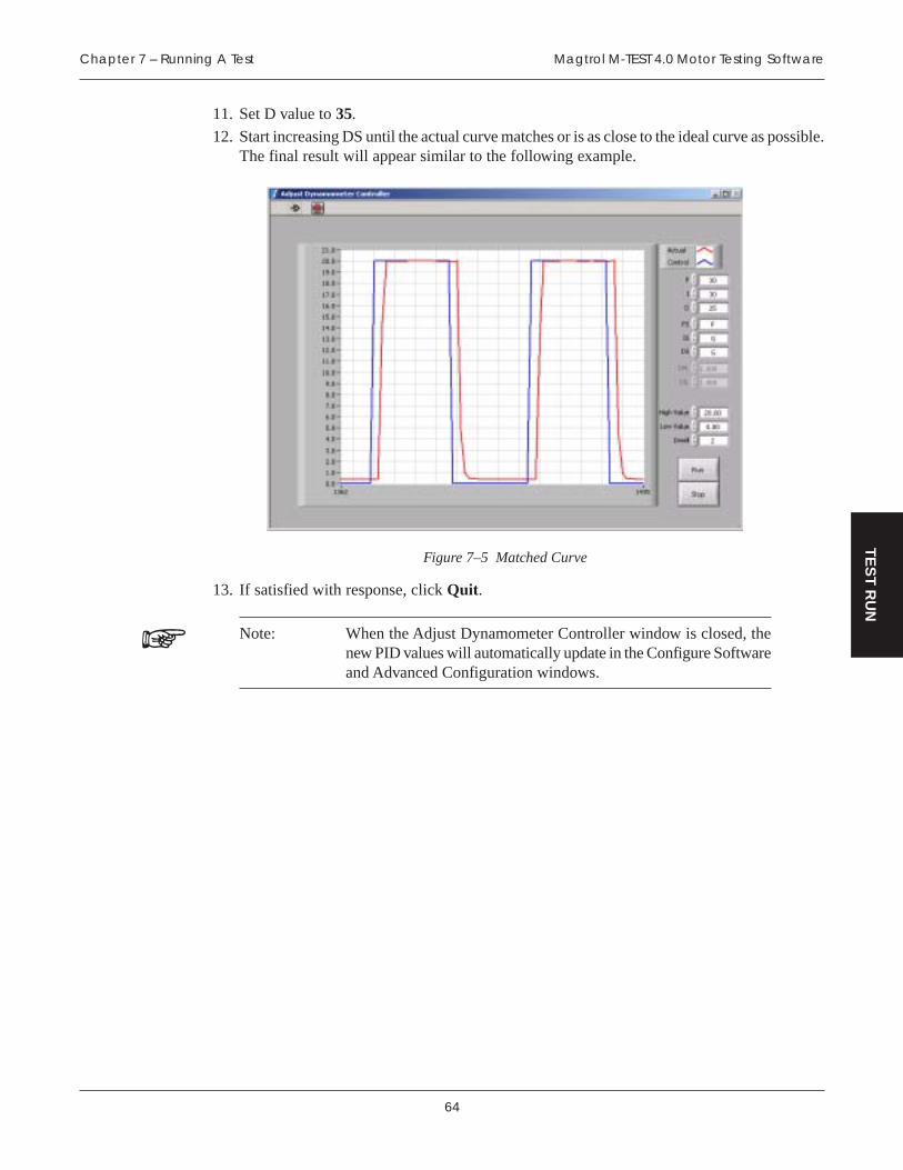
64
Magtrol M-TEST 4.0 Motor Testing SoftwareChapter 7 – Running A Test
TE
ST
RU
N
11. Set D value to 35.
12. Start increasing DS until the actual curve matches or is as close to the ideal curve as possible.The final result will appear similar to the following example.
Figure 7–5 Matched Curve
13. If satisfied with response, click Quit.
Note: When the Adjust Dynamometer Controller window is closed, thenew PID values will automatically update in the Configure Softwareand Advanced Configuration windows.

65
Magtrol M-TEST 4.0 Motor Testing Software Chapter 7 – Running A Test
TE
ST
RU
N
7.3.2 ADJUSTING THE CONTROLLER FOR A RAMP TEST
1. In the Configure Software window under Ramp Test Parameters, turn Dynamic PID ScalingOn.
2. Click Adjust Controller.
3. Set P to 35.
4. Set I and P to 0.
5. Set PS, IS and DS to A.
6. Set DPL, DIL and DDL to 1.
7. Click Run. The result will appear similar to the following example.
Figure 7–6 Ramp (with bump and offset)

66
Magtrol M-TEST 4.0 Motor Testing SoftwareChapter 7 – Running A Test
TE
ST
RU
N
8. If the actual response is not consistent with the ideal response and there is a bump as seen inFigure 7–5, set I to 35. For more information on ideal and actual response, see Section 6.9–Adjust Controller.
9. Click Run. The result will appear similar to the following example.
Figure 7–7 Ramp (with bump)
10. Increase IS value until bump diminishes. While adjusting, click Run between eachadjustment to see results. When optimal setting is reached, the result will appear similar tothe following example.
Figure 7–8 Ramp (no bump but unstable)
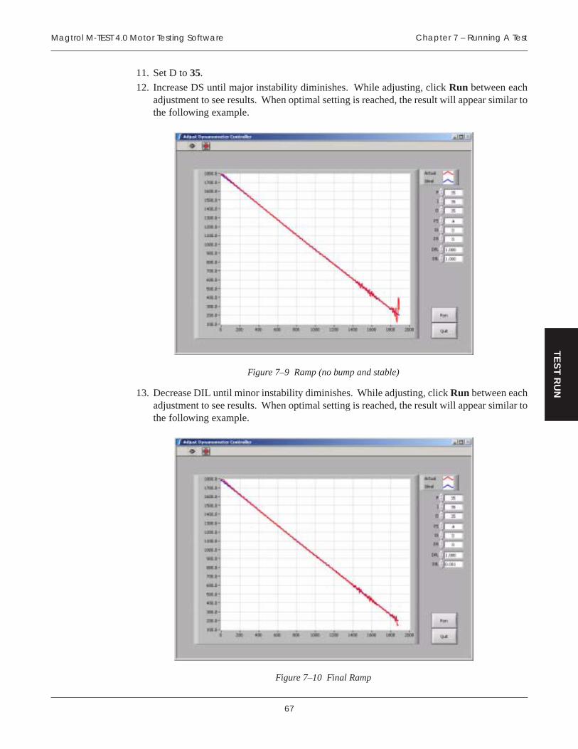
67
Magtrol M-TEST 4.0 Motor Testing Software Chapter 7 – Running A Test
TE
ST
RU
N
11. Set D to 35.
12. Increase DS until major instability diminishes. While adjusting, click Run between eachadjustment to see results. When optimal setting is reached, the result will appear similar tothe following example.
Figure 7–9 Ramp (no bump and stable)
13. Decrease DIL until minor instability diminishes. While adjusting, click Run between eachadjustment to see results. When optimal setting is reached, the result will appear similar tothe following example.
Figure 7–10 Final Ramp
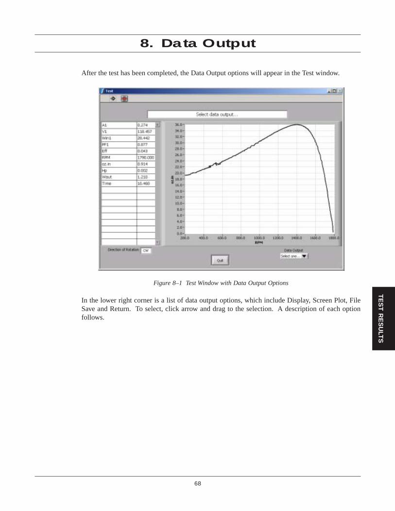
68
TE
ST
RE
SU
LTS
8. Data Output
After the test has been completed, the Data Output options will appear in the Test window.
Figure 8–1 Test Window with Data Output Options
In the lower right corner is a list of data output options, which include Display, Screen Plot, FileSave and Return. To select, click arrow and drag to the selection. A description of each optionfollows.

69
Magtrol M-TEST 4.0 Motor Testing Software Chapter 8 – Data Output
TE
ST
RE
SU
LTS
8.1 DISPLAY
Displays the acquired test data in a tabular format.
Figure 8–2 Display Window
The data can be reviewed by using the scroll bars to the right and at the bottom of the data table.

70
Magtrol M-TEST 4.0 Motor Testing SoftwareChapter 8 – Data Output
TE
ST
RE
SU
LTS
To customize the data, click Configure Print and the following window will appear.
Figure 8–3 Configure Print Window
Select your Desired Data Columns and click OK to automatically return to the Display Window.
Click Print and the customized data that was selected in the Configure Print Window will be sent toyour local printer.
Note: M-TEST 4.0 only has the capability to print 9 columns at a time.If printing more than 9 columns, it is suggested that the file besaved and then printed from another program. The file is formattedas a tab delimited text file that can be easily opened in anyspreadsheet program. For instructions on how to save a file, seeSection 7.3–File Save.
To return to the Test window, click OK.
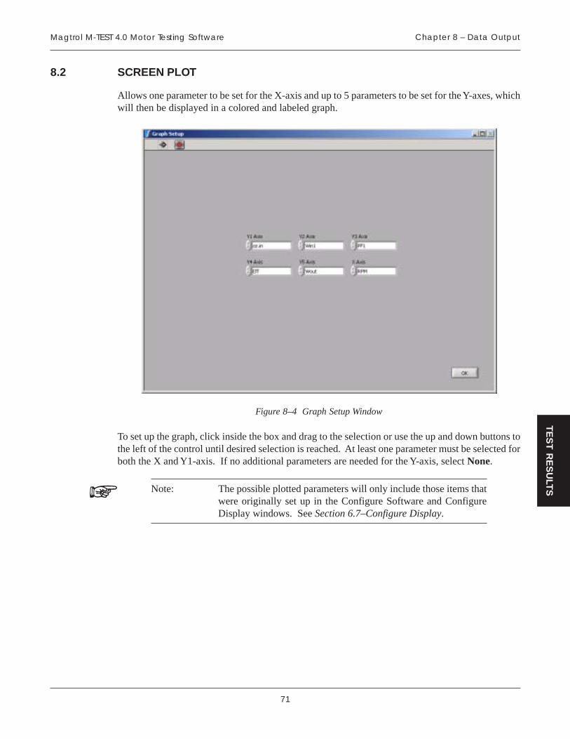
71
Magtrol M-TEST 4.0 Motor Testing Software Chapter 8 – Data Output
TE
ST
RE
SU
LTS
8.2 SCREEN PLOT
Allows one parameter to be set for the X-axis and up to 5 parameters to be set for the Y-axes, whichwill then be displayed in a colored and labeled graph.
Figure 8–4 Graph Setup Window
To set up the graph, click inside the box and drag to the selection or use the up and down buttons tothe left of the control until desired selection is reached. At least one parameter must be selected forboth the X and Y1-axis. If no additional parameters are needed for the Y-axis, select None.
Note: The possible plotted parameters will only include those items thatwere originally set up in the Configure Software and ConfigureDisplay windows. See Section 6.7–Configure Display.
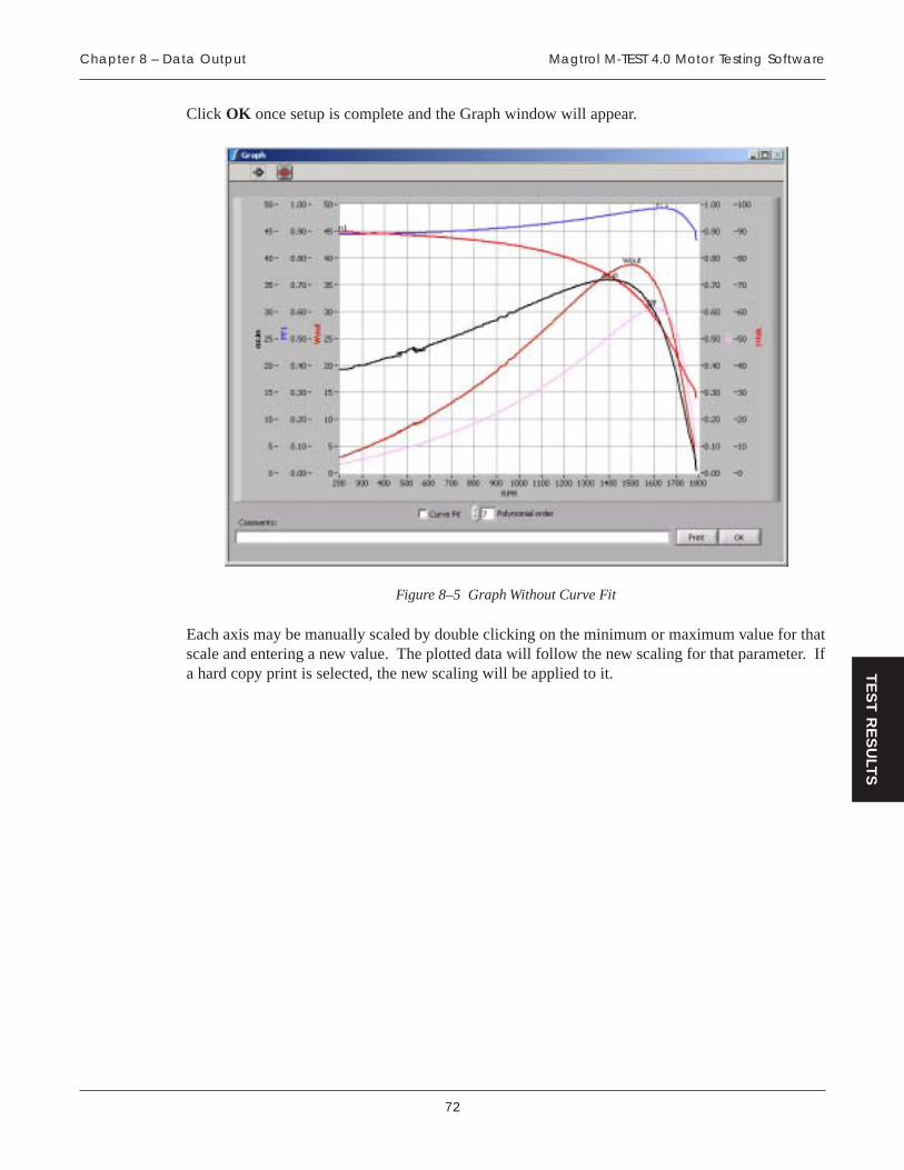
72
Magtrol M-TEST 4.0 Motor Testing SoftwareChapter 8 – Data Output
TE
ST
RE
SU
LTS
Click OK once setup is complete and the Graph window will appear.
Figure 8–5 Graph Without Curve Fit
Each axis may be manually scaled by double clicking on the minimum or maximum value for thatscale and entering a new value. The plotted data will follow the new scaling for that parameter. Ifa hard copy print is selected, the new scaling will be applied to it.

73
Magtrol M-TEST 4.0 Motor Testing Software Chapter 8 – Data Output
TE
ST
RE
SU
LTS
If a smoother curve is preferred, select the Curve Fit check box and adjust the Polynomial order bytyping the value or clicking the up and down arrows to the left of the box. The Polynomial order isadjusted based on appearance and how well the curve approximates the actual data. When the curvereaches desired appearance, the Graph window will appear as follows.
Note: When enabled, the fitted data will be shown with narrow, dashedlines and the raw data will be shown with wide, solid lines.
Figure 8–6 Graph With Curve Fit
Type desired notes into the Comments box and they will appear on the printed document and savedin the data file.
Click Print to send information to printer. If curve fitting is enabled, only the fitted data will beprinted.
To return to the Test window, click OK.

74
Magtrol M-TEST 4.0 Motor Testing SoftwareChapter 8 – Data Output
TE
ST
RE
SU
LTS
8.3 FILE SAVE
When the File Save option is selected, the Save As dialog box will appear.
Figure 8–7 Save As Dialog Box
Select the location where the file should be saved and type the desired File name. Any files savedwill be able to be retrieved at a later date and used for further testing.
8.4 RETURN
Selecting Return will end the Data Output options and return the program to the Main window.
Note: All data from the test will be lost unless the File Save option waschosen or the Data Logging feature was enabled in the SoftwareConfiguration setup. See Section 6.4–Data Logging.

75
Magtrol M-TEST 4.0 Motor Testing Software Chapter 8 – Data Output
TE
ST
RE
SU
LTS
8.5 LOAD FILE
Click Load File from the Main window to retrieve previously stored test data. Open the desiredfile and the Main window will appear with the Data Output option list.
Figure 8–8 Load File Data Output
The Data Output options include Display, Screen Plot and Return. They all function the same asdescribed in Sections 8.1, 8.2 and 8.4. The only Data Output option that is not offered is the FileSave option. The file is already saved, so it is not necessary.

76
HE
LP
9. Troubleshooting
MELBORP NOSAER NOITULOS
kcilC tseTnuR erehtdna.esnopseronsi
neebtonsah0.4TSET-M.derugifnocylreporp
ebtsumerawtfosdnaerawdrahehT.nurebyamtsetaerofebderugifnoc
tnemurtsnignitsetehTehtnidegnahcsawledom
noitarugifnoCdecnavdAdidseulavehtdnawodniw
.etadputon
.stluafeddaoltondiD
kcilctsuM stluafeDdaoL otnottubdnaseulavllaetadpuyllacitamotua
ehtotnistinueuqrotehtmargorp.rellortnoc
ehtecno,yrassecenfI:ETON.detsujdaebnacyeht,teserastluafed
,0.4TSET-MgnitratsnehWegassemgniwollofeht
derrucco7rorrE":sraeppanepO:iv.+eliFnepOta
."eliF
sieliftxt.stluafeDtseT-MehTgnikrowehtnidnuofton
.yrotcerid
kcilC potS yb0.4TSET-MesolC.thgirreppuehtni"X"gnikcilc
-MehtdniF.wodniwehtforenrocehtotevasdnaeliftxt.stluafeDtseT
si0.4TSET-Merehwyrotcerid.detacol
noitacinummoclairesoN.rellortnochtiw
erawdrahro/dnarorreputeS.tluaf
dnaetaRduaB,gnilbackcehC.rellortnocfotropMOC
rezylanarewopesahp-3lliw)0035ro0356,0556(-elgnisniataderiuqcaton
.edomesahp
tonsahrezylanarewopehT.detcennocylreporpneeb
rewopesahp-3agnisunehW-elgnisniataderiuqcaotrezylana
sitahtyrtiucriceht,edomesahpotdetcennocebtsumdetsetgnieb
ehtfolenapraerehtno1esahp.rezylanarewop
-MfonoisivertnerrucehTylreporptonsi0.4TSETredlomorfsputesgnidaol.0.4TSET-Mfosnoisiver
TSET-MfonoisivertnerrucehTputestnereffidevahyam0.4
sawtahwnahtsretemarap.snoisiverredlonidesu
ebotdeenlliwsputestsetweNfonoisivertnerrucehtrofdetaercthgimatadesuaceB.0.4TSET-Mdlognidaolnwodnehwdetrotsideb,noisivertnerrucehtnisputestset
noisiverdloehtnitsetehtnepotnatropmiynadrocerottsrif
daoL,gnilacS,DIP.g.e(sretemarapawoN.).cte,semiTllewD,seulaVehtnidetaerc-erylisaeebnactset
.0.4TSET-Mfonoisivertnerruc
kooltonseodtolpneercSehtgniruddidtisayltcaxe
.tsetevruc
deriuqcasiatad,tsetehtgniruDmumixamehttadettolpdna
siatadtubetarelpmasmetsys.etardenifed-resuehttaderots
lliwetarelpmasehtgnisaercnItolpehtdnastniopataderomerots
.lanigiroehtekileromkoollliw
snmuloCataDderiseDehTtropeRerugifnoCehtni
euqroTwohsylnowodniw.deepSdna
ebotsdeenerawtfosehTehtotgnidroccaderugifnoc
dnaderiuqcaebotatad.deyalpsid
,wodniwerawtfoSerugifnoCehtmorFdloH.nottubyalpsiDerugifnoCkcilc
ehtkcilcdnayektfihSehtnwod.KOkcilC.sretemarapderised
,tsetevrucagninnurelihWsawtahtdoirepllewdehtotmargorpehtdesuactessawtsetehtnehwpukcol
.detrats
gnimitasesuerawtfosehTgnolwohenimretedotnoitcnufegralafI.deriuqcaebnacatad
999,99.g.e(deretnesirebmunelbanusimargorpeht,)setunim
.hsarclliwdnatidaerot
fodoirepgnolaroftsetanuroT.elacsemitelbanosaeraesu,emit
.nim063=sruoh6,elpmaxeroF
If you require additional assistance, please contact Magtrol Customer Service at +1 716-668-5555in the United States or +41 26 407 30 35 in Switzerland.

77
AP
PE
ND
IX
Appendix A: PID/Scaling
A.1 ABOUT THE PID LOOP
The DSP6001 has PID adjustment capability for both the speed and torque modes to provide thebest system response. The PID Loop comprises the following three variables:
P = proportional gain
I = integral
D = derivative
Other important variables include:
• Set point - desired load or speed
• Error - difference between the set point and the actual measurement
A.1.1 P (PROPORTIONAL GAIN)
With proportional gain, the controller output is proportional to the error or to a change in measurement.Deviation from the set point is usually present. Increasing the proportional gain will make the PIDloop unstable. Increasing the integral value will eliminate this instability. For best loop control, setthe proportional gain as high as possible without causing the loop to become unstable.
A.1.2 I (INTEGRAL)
With integral, the controller output is proportional to the amount of time the error is present. Increasingthe integral value eliminates the offset from the set point. If the response becomes oscillatoryincrease the derivative value.
A.1.3 D (DERIVATIVE)
With derivative, the controller output is proportional to the rate of change of measurement or error.Derivative can compensate for a changing measurement. Derivative takes action to inhibit morerapid changes of the measurement than proportional gain.

78
Magtrol M-TEST 4.0 Motor Testing SoftwareAppendix A: PID/Scaling
AP
PE
ND
IX
A.2 HOW THE PID LOOP WORKS
The following diagram demonstrates the correlation between the variables in the PID Loop.
Derivative Proportional
Integral
Set Point
Reading
-
e(t) Yd(t) Yp(t)
Yi(t)
Yt(t)Ys(t)
+ +Scale
A/DPower
AmplifierBrakeCoil
TSC Load CellAmplifier
Amplifier
TORQUE
RPM
SpeedCorrection
Yswb(t)OR
HYST & PB
WB
IIR Filter
Figure A–1 System Block Diagram
A.2.1 PID SCALING FOR HYSTERESIS, EDDY-CURRENT AND POWDER BRAKE DYNAMOMETERS
Yt(t) Ys(t)Scale
TORQUE: TSC1 Ys(t) = Yt(t) / 1.725 * 2
TSC2 Ys(t) = Yt(t) / 1.725 * 2 * 1.6623
SPEED: TSC1 & TSC2 Ys(t) = Yt(t) * 5319.93 / MAX SPEED
A.2.2 SPEED CORRECTION FOR WB (EDDY-CURRENT BRAKE) DYNAMOMETERS
Ys(t) Yswb(t)Speed Correction
The WB Dynamometer follows the same scaling as the HYST and PB with the addition of onecalculation for both torque and speed. This calculation is due to the fact that for a given current thetorque changes with speed. This is referred to as speed correction.
Yswb(t) = (Ys(t) + Ys(t) / speed correction factor) / 2
The speed correction factor is calculated on each entry into the PID loop equations.
Speed Correction Factor = - .0001 x 2 + .0203 x + .005 limited to .051 to 1
where x = RPM / NOMINAL SPEED * 100
NOMINAL SPEED is set by the user and obtained from the data sheets for the dynamometer orbrake.

79
Magtrol M-TEST 4.0 Motor Testing Software Appendix A: PID/Scaling
AP
PE
ND
IX
A.2.3 EQUATIONS
Where Skp, Ski and Skd are system coefficients…
Yd(t) = (e(t) - e(t-3) + 3 * (e(t-1) - e(t-2))) * (10/Skd) * D%
Yp(t) = (e(t) + Yd(t)) * (10/Skp) * P%
Yi(t) = Yi(t-1) + (e(t) + Yd(t)) * (10/Ski) * I%
Yt(t) = Yp(t) + Yi(t)
Ys(t) = Scale * Yt(t)
A.3 PID SCALING
PID Scaling is a multiplier of the P, I or D term. Due to the fact there are so many differentdynamometer types and motor combinations, this multiplier is needed to extend the range of thePID. The letters represent the following:
A = 0.001 F = 0.5
B = 0.005 G = 1
C = 0.01 H = 5
D = 0.05 I = 10E = 0.1
In using the multiplier, the user can input PID numbers from .001 (.001 x 1%) to 990 (10.0 x 99%)with good resolution.
A.4 DYNAMIC PI SCALING
In some cases, PI values that have been fine-tuned for best system response at higher speeds will notbe suitable at lower speeds. The DSP6001 allows the use of dynamically changed PI values tocorrect this. When the DPL or DIL controls are set at 1.000, the PI coefficients remain constantbetween the free run speed and minimum speed. Changing any control to a value less than 1.000dynamically changes the P or I from 1.000 at free run to the control value times the starting value,at minimum speed.
For example, a DIL of 0.010 produces an I term of 1/100th the starting value at the end of the ramp.
Note: This feature is available only during a Ramp Test.
A.4.1 SETTING THE PID FOR RAMP DOWN
It is nearly impossible to select a PID value that optimizes the control loop over a wide range ofspeed. With Magtrol's experience in motor testing, our engineers have developed a dynamic PIDalgorithm. The PID values change with the Speed Set Point. In most cases, the PI values are highwhen the motor is lightly loaded and tend to decrease at higher loads.
M-TEST 4.0 provides a setup PI function in the setup for the ramp test. In the program, the dynamicscaling can be enabled or disabled and the span of the scaling can also be selected. See Section 6.6–Ramp Test Parameters.

80
Magtrol M-TEST 4.0 Motor Testing SoftwareAppendix A: PID/Scaling
AP
PE
ND
IX
Figure A–2 Ramp Down Low I
Ramp shows low value for I term. Note “bump” at beginning of ramp and good results toward endof ramp.
Figure A–3 Ramp Down High I
Ramp shows higher value for I term. Note “bump” at beginning of ramp has been reduced but thereare poor results toward end of ramp.

81
Magtrol M-TEST 4.0 Motor Testing Software Appendix A: PID/Scaling
AP
PE
ND
IX
Figure A–4 Ramp Down Dynamic I
Ramp shows Dynamic Scale effect. Note “bump” at beginning of ramp has been reduced and thereare good results toward end of ramp. DIL was set to 0.01. At the end of the ramp, the I term is 1/100th of the starting value.

82
APPENDIX
Ap
pe
nd
ix B
: M-TE
ST 4
.0 F
low
Ch
art
The follow
ing flow chart is a representation of how
M-T
ES
T 4.0 is organized and show
s, at a quick glance,w
here all the main features are located w
ithin the program.
ADVANCED
CONFIGUREHARDWARE
CONFIGUREDISPLAY
CONFIGUREREPORT
ADJUSTCONTROLLER
CONFIGURESOFTWARE
CONFIGUREPRINT
PRINTDISPLAY
CONFIGUREPRINT
PRINTDISPLAY
DISPLAY
PRINTGRAPH
GRAPH
GRAPHSETUP
SCREENPLOT
FILESAVE
PRINTGRAPH
GRAPH
GRAPHSETUP
SCREENPLOT
RETURN
RETURN
RUN TEST SAVE SETUP
DISPLAY
LOAD SETUP LOAD FILE EXIT
M-TEST 4.0MAIN WINDOW

83
AP
PE
ND
IX
Appendix C: Software Revision History
Release Date Revisions
1.0 04/27/2001 Initial release.
1.1 05/02/2001 Disable Max. Temp if no TC HW.Disable Max. Current if no PA.Disable LR Dwell if Dyn-CF.Set Dyn-CF if IC = Prev. Val or No.Disable unused PID controls if not Torque or Speed Curve.Increased range of Max. Temp and Max. Current controls.Coordinated graying out of PID controls to test type.Fixed range of some controls mysteriously reset to 100 max.Added DC power supply control in Adjust Dyno Controller.Changed timer from counting seconds to horizontal slide bar.Changed background color of Adjust Dyno Controller curve graph.Fixed efficiency and time showing >0 at free run.Config Report wasn’t recalled.
1.2 05/14/2001 Added Recalculate Data.vi so PF, Eff, Wo and Hp are shown properly.Added 6530 programming and calculations.Grayed PS, IS, DS in Adjust Dyno when using Amps or Watts Curve.Fixed Max. Current control not showing in Config. SW.Reset Load with ‘R’ for Amps or Watts curves.Coerced I to 0 if calculated to be >99.99.
1.3 05/17/2001 Fixed report sometimes showing extra blank line.Changed to Waveform Graph if Manual Test selected with X-axis = Time; This fixed graph buffer
being overloaded and slowing down screen response.Added ‘Test Running’ message to Manual Test.
1.4 05/30/2001 Fixed File Open inserting extra blank data column.Edited descriptions of Avg-D/U and Dyn-CF ramp tests.Added Serial Port Init to Advanced Initialization.Fixed baud rate settings.Made serial port reads more robust.
1.5 06/04/2001 Advanced Config would not show last HD dyno model.
1.6 06/14/2001 Fixed serial port control not allowing COM1.Added absolute value to Eff, Wout, and Hp.Removed -1 function for serial port in Output Raw Ramp Data.vi.Copied serial port read routine to Aux. input.
1.7 06/27/2001 Changed waveform chart to scope update mode.If curve test is N or Q stabilized, send command only on change of value.Added 500mS GPIB timeouts to Send Command and Read Instruments.Use I99.99 to lock rotor after fast ramp down in Avg D/U test.Fixed column headers not coming back correctly from file.
1.8 09/25/2001 Added Max Brake Current control to Avg D/U ramp test.If maximum torque limit is reached in Avg D/U ramp, cancel locked rotor test.On report printout, limited special fields to 3 digits of precision.Added ramp start speed to ramp up in Avg D/U.Removed line feed from serial commands for DSP6000.

84
Magtrol M-TEST 4.0 Motor Testing SoftwareAppendix C: Software Revision History
AP
PE
ND
IX
Fixed File Save adding extra tab, and File Open deleting last column. Now, file may be edited inExcel, saved as tab delimited text, and recalled OK.
Added Zimmer LMG310 to power analyzer menu.Fixed TC labels not showing up properly on graph.Added curve fit option for graph on generated report.Set power analyzer to local after adjust dyno routine.Added ability to select column parameters for printout.Fixed curve test where requesting a torque going from some value to zero stayed at that value.
1.9 02/20/2002 Added Pass/Fail testing.Fixed Graph Visible control.Added Fieldpoint hardware selection for temperature measurement.Fixed Manual Test - Quit - Cancel function not canceling.Made thermocouple label name show up on test-graph axis instead of just “Thermocouple”.Made graph update on screen after Ramp, Dynamic-CF, Previous Value test.Fixed quit from adjust dyno controller dropping motor to stall temporarily.Added Maximum Speed for Ramp test. This keeps motors from running away at free run. PID’s must
be set to reasonable value first since this is a speed stabilized function.Removed unused columns from printout of data if there are less than nine.In Configure Display, made the torque selection show the units selected.Generated, one page report can now be saved and recalled for viewing and printing.Added 6510e.Made sampling rate entry of 0.01 seconds in manual test default to fastest possible acquisition.Added 5240/4629B controllers.Added Open Loop Curve test.Changed defaults on Config SW to Torque Curve.Added description of scaling letters for QPS-QDS and NPS-NDS.Added second control in Adjust Dyno Controller so that you can step between two load points
instead of just no-load and some load.Changed Pre-Test Init. so that Max Speed Excited values are recalled when using PB’s.Added 3 Hz filter selection.Fixed curve test so that if you are in a torque or speed dwell period, the command is sent just once.Changed format of saved data in Pass/Fail test so it is easier to work with in Excel.Changed torque units for SI to mN.m, cN.m and N.m.Fixed Curve and Pass/Fail tests where not ending with a zero load value caused no loading the next
time the test was run. Shift register was not being re-initialized.
2.0 03/15/2002 Added absolute value to Graph and Print Graph so negative values can be plotted.Otherwise, they disappear from the plot.
Fixed Channel 2 Torque/Aux Scale Factor not being pulled from defaults file.Added capability of up to 4 FP modules (32 thermocouples).Re-wrote Average Down/Up Array with better programming, and to eliminate any data below minimum
speed.Fixed a minor problem with report graph not showing data properly unless the selection was first
changed to something else.
2.1 07/24/2002 Re-sized Curve Test graph so Y-axis values greater than 9999.9 don’t have the MSD cut off.Programs re-compiled in LabVIEW 6.0.2.Fixed logic error when entering special speed or torque points in Ramp Test.LV 6 conversion problems: Spreadsheet String to Array functions differently.LV 6 conversion problems: Pass/Fail table didn’t scroll.
2.2 08/02/2002 After many problems surfaced with LV6, went back to LV5. Need to make it workwith FP3.0.1

85
Magtrol M-TEST 4.0 Motor Testing Software Appendix C: Software Revision History
AP
PE
ND
IX
2.3 10/01/2002 Re-compiled with FP 3.0.1 and NI-DAQ 6.9.1 drivers.Re-wrote File Open.vi with better programming.Added Yokogawa WT1600 power analyzer.Stopped Manual Test from sending any hidden PID values to controller.Saves graph axis settings.Added offset control for DAQ temperature measurement.Added ability to select special torque and speed points during ramp test at the same time.
2.4 03/06/2003 Updated Sorensen DCS to DHP.Changed quit from ramp so locked rotor is not performed.Fixed bug in wiring mode for LMG310 in 3ph. 3w. 3m. star and 3(2)ph. 3w. 2m.Added any comments from screen plot to the saved file.Show both raw data plot and curve fit at the same time on display only, not on print.Changed report path to report directory and used serial number + .rpt for filename. Access filedialog with a button next to field.Added button next to data directory to access file dialog. This now becomes active when data
logging is enabled but not in Pass/Fail test.Added buttons next to pass filename and fail filename to access file dialog. This now becomes the
drive/path/filename for Pass/Fail data storage.Added button for file dialog to import data from tab-delimited text file in the following tests:Curve
-control data, Ramp - special speed and torque points, Pass/Fail - control data and limits.Enlarged white fields in data logging and control data.Improved quit function from adjust controller routine. One press stops routine, another press quits.Modified code so correct maximum power and maximum torque get sent to DSP6001 when using
tandem dyno.Added Volts column to Pass/Fail table for controlling power supply at different levels (just like the
curve test).Added delay after turn on of DC power supply before software checks for shaft rotation.Fixed “Ramp Test Parameters” label to 13 point application font. Caused small text on Win2k OS.When waiting for motor to reach freerun, you can use the Quit button to stop the procedure.Made screen plot Y1 and X axis selectors default to “None” to correct LabVIEW quirk.Fix special torque and speed points routine so program doesn’t lock up if value is outside data set.Fixed File Open from pulling in last data point as a comment if file didn’t contain one.Made 6510, 6510e, 6530 and 6550 power analyzers auto-range on Volts.Added HP66xx series power supplies.Fixed appearance of some text and buttons when using Win 2000.Changed to short data labels for column headers.Changed report path to accept multiple points (.) in name, not just the file extension.
2.5 06/23/2003 Rewrote M-TEST using LabVIEW 6.1Changed 6510 so volts does not autorange during test. This is because it can't do this!Changed graphing routine so that you may rescale any axis to your liking. The rescaled axes willbe plotted as such, if selected.Fixed freerun data not being included in complete data set.Removed the CJC reading from the data display when using multiple FieldPoint modules.Added Tandem code.Changed Adjust Dynamometer routine so that you can pre-set controls before starting motor.
2.6 07/21/2003 Added command to turn power supply back on after Next Test is selected in Pass/Fail mode.Added check for RPM if using a tandem dynamometer and changing the advanced configuration.Added Lambda Genesys power supply.Added tip strips to all front panel controls.

86
Magtrol M-TEST 4.0 Motor Testing SoftwareAppendix C: Software Revision History
AP
PE
ND
IX
2.7 02/03/2004 Fixed last line of data not being recalled if no comment was added to data file.Added color to printed plots.Fixed Gain and Offset being reversed in Read Instruments DAQ vi.Configuration Save and Load using keys. Allows existing configurations (starting in Rev. 2.7) to be
used in future program revisions.Added programmable external shunt support for 6510e and 6530.Added gear box ratio.Fixed PF calculation for 6530 and 6550 when in 3ph. 3w. and 3ph. 3V 3A modes.Pass/Fail window now shows actual measured load point value, not the requested value.Pass/Fail failure is now flagged by a white on red highlighted cell instead of asterisks.Removed "Recalculate Data.vi". Not needed after PF was fixed. Caused bad Eff. calculation.
2.8 5/13/2004 Changed "Please Start the Motor…" routine to wait until a speed signal is generated and the buttonis pressed.
Added Pass/Fail checking for direction of rotation.Added Sorensen DCS to power supply list.Removed tip strips (more annoying than helpful).Fixed Y-axis label not indicating thermocouple name on test graph.Added dynamometer pre-load function for DSP6001. Open loop value stays active at all times.Fixed a bug in the configuration save/load where tables that contain more than nine columns were
not being recalled properly.
2.81 5/19/2004 Allows 5300 to be used as three single phase analyzers. Efficiency is calculated from Watts onphase 1 only.
2.9 8/12/2004 Fixed 4629B/5240 torque conversion on writes during Curve and Pass/Fail tests.Added Output kW to displayed and control parameters.Changed mechanical action on Config HW and Config SW buttons so they don't latch down with
fast computers.
3.0 11/03/2004 Changed order of N and F commands in ramp test and adjust dyno controller routine to solveproblem with maximum speed being limited incorrectly on the DSP6001.
Fixed quit during ramp down from resetting the maximum speed command.Another bug fixed in 4629B/5240 torque conversion on writes.Added Staco control as standard feature.
3.1 11/24/2004 Corrected efficiency calculation for 6530 and 6550 1-phase 2-wire.Added two button dialog for "Please start the motor…". Allows you to cancel out of the loop.No longer resets the High Value, Low Value and Dwell upon entry into Adjust Dyno Controller.

87
Index
AActive Channel 25Adjust Controller 56Adjust Dynamometer Controller Window 56Advanced Configuration Window 22Alarms 25AMUX-64T 12Average-D/U (Down/Up) 27
BButtons 15
CChannels 23Configure Display 51–52Configure Display Window 51Configure Hardware 14Configure Hardware Window 17Configure Report 53–55Configure Report Window 53Configure Software 15Configure Software Window 38Control Data 44Controller Adjustment 62–67Controller Setup 20, 39Controls
Inaccessible 16Setting 16
Correction Factor Calculation 29Curve Test
Configuration 59Controller Adjustment 62–64Description 31Parameters 42Setup Routine 56
DDAQ Board 10Data Logging 40Data Output
Graphical 71–73Tabular 69
Data Points 48Data Sheet 3Derivative 77. See also PIDDisplay 69Display Window 69Dynamic PI Scaling 79Dynamic-CF 29
EExit 15
FFeatures 2FieldPoint. See National Instruments FieldPointFile Save 74
GGPIB Board 8GPIB Driver Software 7GPIB Interface 7Graph Setup Window 71Graphical Data Output. See Screen Plot
HHardware Configuration 17–21
Advanced 22–25
IInstallation
GPIB Board 8GPIB Driver Software 7M-TEST Software 6Procedure 6Temperature Board 11, 12Temperature Driver Software 10, 12
Integral 77. See also PID
LLoad Defaults 25Load File 15, 75Load Setup 15
MM-TEST Defaults File 25Main Window 14Manual Test
Configuration 61Description 33Parameters 42
Menus. See WindowsMT-TEST 4.0. See Temperature Measurement Option
NNational Instruments FieldPoint 12National Instruments NI-DAQ 10National Instruments PCI-6024E Multifunction I/O b 11network interface 12NI-488.2 Software 7NI-488.2 Troubleshooting Wizard 8

88
Magtrol M-TEST 4.0 Motor Testing SoftwareIndex
NI-DAQ for Windows 10
PPass/Fail Test
Configuration 61Description 33Parameters 49–50
Password Protection 18, 38PID Loop 77, 78PID Scaling 78, 79PID Settings 77, 79, 82Power Measurement Setup 19Power Supply Setup 18Proportional Gain 77. See also PID
RRamp Down 79Ramp Test
Configuration 60Controller Adjustment 65–67Description 26Parameters 45Setup Routine 56
Report Configuration 53–55Reports
Sample 55Return 74Revision History
Software Program 83User's Manual ii
RS-232 Interface 7, 10Run Button 15Run Test 15
SSave Setup 15Saving Files 74SCB-68 11Screen Plot 71–73Setting Controls 16Software Configuration 38Software Installation 6, 7, 10Software Revision History 83Speed Correction 78Stop Button 15System Requirements 1
TTabular Data Output. See DisplayTemperature Board 11, 12Temperature Driver Software 10, 12Temperature Measurement Option 10Temperature Measurement Setup 21Temperature Unit Changes 13
Test ConfigurationHardware 59Software 59
Test ParametersCurve 42Manual 42Pass/Fail 49–50Ramp 45
Test Setup 39Test Window 60Tests
Average-D/U 27Curve 31Dynamic-CF 29Manual 33Pass/Fail 33Ramp 26
ThermocoupleConnections 11, 12Input Module 12Type 13
Troubleshooting 76
WWindows
Adjust Dynamometer Controller 56Advanced Configuration 22Configure Display 51Configure Hardware 17Configure Report 53Configure Software 38Display 69Graph Setup 71Main 14Test 60

Magtrol, Inc. warrants its products to be free from defects in material and workmanship under normal use andservice for a period of one (1) year from the date of shipment. Software is warranted to operate in accordance withits programmed instructions on appropriate Magtrol instruments. This warranty extends only to the original purchaserand shall not apply to fuses, computer media, or any other product which, in Magtrol’s sole opinion, has beensubject to misuse, alteration, abuse or abnormal conditions of operation or shipping.
Magtrol’s obligation under this warranty is limited to repair or replacement of a product which is returned to thefactory within the warranty period and is determined, upon examination by Magtrol, to be defective. If Magtroldetermines that the defect or malfunction has been caused by misuse, alteration, abuse or abnormal conditions ofoperation or shipping, Magtrol will repair the product and bill the purchaser for the reasonable cost of repair. If theproduct is not covered by this warranty, Magtrol will, if requested by purchaser, submit an estimate of the repaircosts before work is started.
To obtain repair service under this warranty, purchaser must forward the product (transportation prepaid) and adescription of the malfunction to the factory. The instrument shall be repaired at the factory and returned topurchaser, transportation prepaid. MAGTROL ASSUMES NO RISK FOR IN-TRANSIT DAMAGE.
THE FOREGOING WARRANTY IS PURCHASER’S SOLE AND EXCLUSIVE REMEDY AND IS IN LIEU OFALL OTHER WARRANTIES, EXPRESSED OR IMPLIED, INCLUDING BUT NOT LIMITED TO ANY IMPLIEDWARRANTY OF MERCHANTABILITY, OR FITNESS FOR ANY PARTICULAR PURPOSE OR USE.MAGTROL SHALL NOT BE LIABLE FOR ANY SPECIAL, INDIRECT, INCIDENTAL, OR CONSEQUENTIALDAMAGES OR LOSS WHETHER IN CONTRACT, TORT, OR OTHERWISE.
CLAIMS
Immediately upon arrival, purchaser shall check the packing container against the enclosed packing list and shall,within thirty (30) days of arrival, give Magtrol notice of shortages or any nonconformity with the terms of the order.If purchaser fails to give notice, the delivery shall be deemed to conform with the terms of the order.
The purchaser assumes all risk of loss or damage to products upon delivery by Magtrol to the carrier. If a productis damaged in transit, PURCHASER MUST FILE ALL CLAIMS FOR DAMAGE WITH THE CARRIER to obtaincompensation. Upon request by purchaser, Magtrol will submit an estimate of the cost to repair shipment damage.
Magtrol Limited Warranty
89

www.magtrol.comTesting, Measurement and Control of Torque-Speed-Power • Load-Force-Weight • Tension • Displacement
MAGTROL INC70 Gardenville ParkwayBuffalo, New York 14224 USAPhone: +1 716 668 5555Fax: +1 716 668 8705E-mail: [email protected]
MAGTROL SARoute de Moncor 4B1701 Fribourg, SwitzerlandPhone: +41 (0)26 407 3000Fax: +41 (0)26 407 3001E-mail: [email protected]
Subsidiaries in:• Germany• France• Great Britain
Worldwide Networkof Sales Agents ISO 9001
CE
R
T IFIC ATI ON
SWISS
Magtrol SA ISO 9001:2000 certified
Related Documents


