21 COLLET HOLDER Hi-ART MILLING CHUCK DETa-1 Collet Holder DTA DTB DTE CTH CTA ART Pull collet type collet chuck Taper collet chuck Needle-roller type chuck Retension knob P. 64 RED SCREW arbor RSG The arbor for screw-in End Mill SUMMIT SLZ End-mill holder for ultra-heavy duty application FMH RIGID type FMH-H The face mill arbor for through-spindle coolant P. 22 P. 32 P. 40 P. 48 P. 43 P. 46 Carbide integral type Carbide core M /C Tool MICRO HEAD MFA MBH MBJ Fine adjustment boring holder P. 55 FMH P. 53 Cutter arbor with spindle-through coolant

Welcome message from author
This document is posted to help you gain knowledge. Please leave a comment to let me know what you think about it! Share it to your friends and learn new things together.
Transcript
21
COLLET HOLDER
Hi-ART MILLING CHUCK
DETa-1 Collet Holder
DTADTBDTE
CTHCTA
ART
Pull collet type collet chuck
Taper collet chuck
Needle-roller type chuck
Retension knob
P. 64
RED SCREW arborRSGThe arbor for screw-in End Mill
SUMMITSLZEnd-mill holder for ultra-heavy duty application
FMH RIGID typeFMH-HThe face mill arbor for through-spindle coolant
P. 22
P. 32
P. 40
P. 48
P. 43
P. 46
Carbide integral type
Carbide core
M / C Tool
MICRO HEADMFAMBHMBJ
Fine adjustment boring holder
P. 55
FMH
P. 53
Cutter arbor with spindle-through coolant
Tech
nica
lIn
form
atio
nW
ire
EDM
fixt
ure
Mai
nten
ance
Too
lM
easu
ring
Equi
pmen
tJI
GG
ener
al P
urpo
se T
ool
HSK-
T To
olin
g Sy
stem
sfo
r Tur
ning
Mill
M/C
Too
l
A
NG
LE H
EA
D
Tech
nica
lIn
form
atio
nW
ire
EDM
fixt
ure
Mai
nten
ance
Too
lM
easu
ring
Eq
uipm
ent
JIG
Gen
eral
Pur
pose
Too
lHS
K-T
Tool
ing
Syst
ems
for T
urni
ng M
illM
/C T
ool
AN
GLE
HE
AD
Coolant-throughCoolant-through
22
DE
Ta-1
CO
LLE
T H
OLD
ER
DTA
Spanner
Wrench
Nut-tightening type of easy operation
DTBFor high-speed cutting, High cost performance
DTEFully applicable for coolant-through Wrench
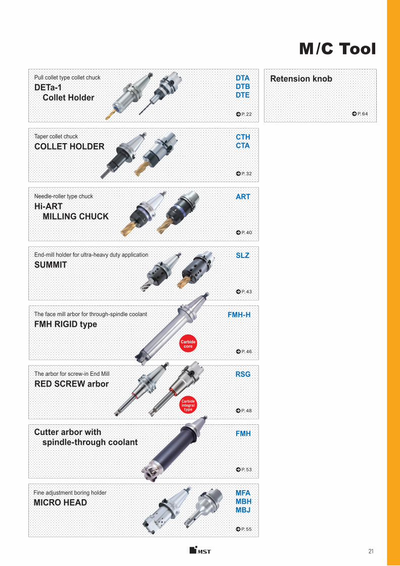
Just 6 collets is all it takes to chuck 106 sizes of drills. Slim design due to no tightening nut at the tip of holder. Compatible with synchronized tapping.
Provides simple tooling lay-out.
DETa-1 Collet Holder
Drill TapEndmill
2mm collapsibility with just one collet !!
Pull collet design
φD
DTE 7 29DTE12 40
The elastic deformation portion that achieves large collapsibility
Collet guide
12 segments precise chucking
2Collapsibility
mm
Pull collet type collet chuck
Draw nut
Pin
Rod
Ring
DETa-1 ColletDETa-1 Collet
Rod
Draw bolt
Retention knob with hole
3 types of coolant- through systems available using coolant cap & spacer P. 30
D
DETa-1 Collet
DTA12DTB12DTE12
DTA7DTB7DTE7
DTA3DTB3
Longer cutter life using through-spindle capability
L
D
Tech
nica
lIn
form
atio
nW
ire
EDM
fixt
ure
Mai
nten
ance
Too
lM
easu
ring
Equi
pmen
tJI
GG
ener
al P
urpo
se T
ool
HSK-
T To
olin
g Sy
stem
sfo
r Tur
ning
Mill
M/C
Too
l
A
NG
LE H
EA
D
Tech
nica
lIn
form
atio
nW
ire
EDM
fixt
ure
Mai
nten
ance
Too
lM
easu
ring
Eq
uipm
ent
JIG
Gen
eral
Pur
pose
Too
lHS
K-T
Tool
ing
Syst
ems
for T
urni
ng M
illM
/C T
ool
AN
GLE
HE
AD
DE
Ta-1
CO
LLE
T H
OLD
ER
23
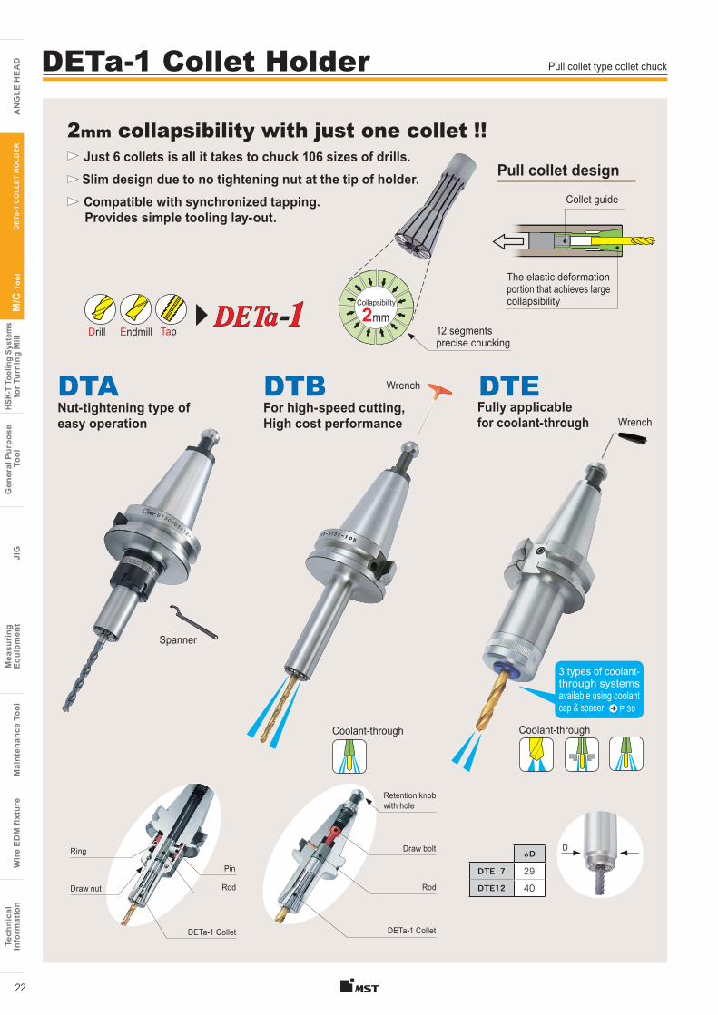
ColletRun-out accuracy(μm)
D3 D7/D12Precision Collet
Standard Collet
Highest guaranteed accuracies throughout entire chucking range (100% inspection).
※Accuracy of collet alone, ( ) means collapsibility usable.
70
50
φ2.5〜13
Multiple coolant supply systems. The best methods can be chosen from three options.
Slim and compact without the nut at the tip.
Coolant-through system
For a cutting tool with oil holes. The shank of the cutting tool is sealed with an O-ring, enabling reliable coolant supply. Compatible with small-diameter cutting tools starting from 3 mm.
Coolant is supplied through the slits in the collet. No dedicated optional parts are required.
Coolant-through cutter
Coolant-through collet
DTB typeDTE type
High-pressure coolant performance can be obtained even when using a cutting tool without oil holes.
“SUKIMA-through” coolant-around tool
DTE type
DTE type
DTA type DTB type
Reduces the number of conventional collets needed by 90% (in-house comparison)
Only one collet!
(D12-8)
Ten collets
φ1〜7
40
φ0.5〜3.175
φ6〜8
Fewer collet types
means easier collet
management !
Uses a maraging steel.
Initial accuracy lasts
for a long period
of time.
6 pcs.
8 pcs.
8 pcs.
3 ( 6)
10 (15)
5 (10)
5 (10)
Size φD 3 type 10 7 type 2112 type 30
Using a high-precision collet will increase the life of your tools.
P. 117
P. 117
7 Mpa
Pressure
φD
φD
D12 Collet
D7 Collet
D3 Collet
The collet holder is pre-balanced by previously designing the holder to be as axisymmetrical as possible. When used with the precision collet, it enables stable machining during high-speed machining.
Both large collapsibility and precise chucking achieved by the pull collet design.
Pre-balanced design (DTE type)
D L〜10 4×D
10〜13 40
Tech
nica
lIn
form
atio
nW
ire
EDM
fixt
ure
Mai
nten
ance
Too
lM
easu
ring
Equi
pmen
tJI
GG
ener
al P
urpo
se T
ool
HSK-
T To
olin
g Sy
stem
sfo
r Tur
ning
Mill
M/C
Too
l
A
NG
LE H
EA
D
Tech
nica
lIn
form
atio
nW
ire
EDM
fixt
ure
Mai
nten
ance
Too
lM
easu
ring
Eq
uipm
ent
JIG
Gen
eral
Pur
pose
Too
lHS
K-T
Tool
ing
Syst
ems
for T
urni
ng M
illM
/C T
ool
AN
GLE
HE
AD
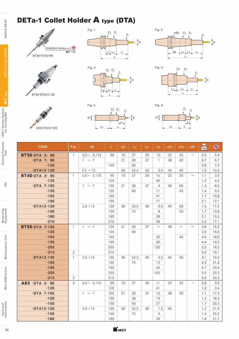
CODE Fig. φD L φC L1 L2 L3 φC1 φC2 φD1
BT30-DTA 3- 90 1 0.5〜 3.175 90 10 27 26 15 22 25 ー 0.5 2.4-DTA 7- 90 1 〜 7 21 30 37 1 38 42 0.7 6.7
-120 120 60 0.8 7.9-DTA12-120 2.5 〜13 30 52.5 42 3.5 45 45 1.0 10.4
BT40-DTA 3- 95 1 0.5〜 3.175 95 10 27 26 15 22 25 ー 1.1 3.9-125 125 45 1.2 4.3
-DTA 7-105 1 〜 7 105 21 38 37 3 38 60 1.3 8.5-135 135 60 11 43 1.4 9.5-165 165 41 1.7 10.8-195 195 71 2.1 12.1
-DTA12-120 2.5〜13 120 30 52.5 40 0.5 45 58 1.5 11.6-150 150 75 8 50 1.7 13.8-180 180 38 2.1 15.5-210 210 68 2.6 17.1
BT50-DTA 7-105 1 1 〜 7 105 21 30 37 ー 38 ー ー 3.8 15.5-135 135 60 3.9 16.6-165 165 30 43 4.0 18.0-195 195 60 4.4 19.5-255 255 120 5.0 18.2-315 2 315 5.9 19.1
-DTA12-135 1 2.5〜13 135 30 52.5 40 4.5 45 50 4.1 19.4-165 165 75 12 4.3 21.6-195 195 42 4.7 23.4-255 255 102 5.5 22.3-315 2 315 6.6 23.3
A63 -DTA 3- 90 3 0.5〜 3.175 90 10 27 26 11 22 25 ー 0.8 3.0-120 120 41 1.0 3.4
-DTA 7-105 1 〜 7 105 21 30 37 12 38 50 1.1 17.3-120 120 38 19 1.3 18.3-150 150 60 27 1.7 20.3
-DTA12-120 2.5〜13 120 30 52.5 40 1.5 45 1.2 21.9-150 150 75 9 1.4 25.2-180 180 39 1.8 27.7
DETa-1 Collet Holder A type (DTA)
24
DE
Ta-1
CO
LLE
T H
OLD
ER
S32ーDTA12ー100
C2 C1C
L3L
D
L2 L1
Fig. 3 Fig. 4C2 C1 C1
C C
L3L
D D
L2 L1
Fig. 5 Fig. 6C2 C1 C1
D1 D1
C C
L L
D D
L2 L2L1 L1
C2 C1C
L3L
60
D
L2 L1
φ60
BT50ーDTA12ー135
NP. 118
C2
L3LL2 L1
Fig. 1 Fig. 2
BT30ーDTA3ー90
Imbalance value(g・mm)
Tech
nica
lIn
form
atio
nW
ire
EDM
fixt
ure
Mai
nten
ance
Too
lM
easu
ring
Equi
pmen
tJI
GG
ener
al P
urpo
se T
ool
HSK-
T To
olin
g Sy
stem
sfo
r Tur
ning
Mill
M/C
Too
l
A
NG
LE H
EA
D
Tech
nica
lIn
form
atio
nW
ire
EDM
fixt
ure
Mai
nten
ance
Too
lM
easu
ring
Eq
uipm
ent
JIG
Gen
eral
Pur
pose
Too
lHS
K-T
Tool
ing
Syst
ems
for T
urni
ng M
illM
/C T
ool
AN
GLE
HE
ADCODE Fig. φD L φC L1 L2 L3 φC1 φC2 φD1
A100 -DTA 7-135 3 1 〜 7 135 21 30 37 39 38 50 ー 2.7 33.8 -165 165 60 2.8 35.5 -225 225 99 3.7 33.6
-DTA12-135 2.5〜13 135 30 52.5 40 13.5 45 2.7 37.1 -165 165 75 21 2.9 40.4 -225 225 81 3.8 39.7E32 -DTA 3- 75 4 0.5〜 3.175 75 10 27 26 2 22 25 ー 0.2 1.8E40 -DTA 3- 75 4 0.5〜 3.175 75 10 27 26 2 22 25 ー 0.3 1.7E50 -DTA 3- 80 4 0.5〜 3.175 80 10 27 26 1 22 25 ー 0.5 2.1F63 -DTA 3- 90 4 0.5〜 3.175 90 10 27 26 11 22 25 ー 0.8 2.3 -120 120 41 27 26 0.9 2.7DN40A-DTA 3- 95 1 0.5〜 3.175 95 10 27 26 10.8 22 25 ー 1.1 4.6 -125 125 40.8 1.2 5.0
-DTA 7-105 1 〜 7 105 21 30 43.8 12.1 38 45 1.2 11.9 -135 135 60 37 18.9 1.3 14.4
-DTA12-130 2.5〜13 130 30 52.5 56.9 ー 45 ー 1.5 18.0 -160 160 75 66.4 1.7 20.0DN50A-DTA 7-135 1 1 〜 7 135 21 60 37 3 38 50 ー 3.4 20.1 -165 165 33 43 3.6 20.0 -195 195 63 3.9 20.6
-DTA12-135 2.5〜13 135 30 52.5 40 7.5 45 50 3.6 21.5 -165 165 75 15 3.8 25.8 -195 195 45 4.2 26.4CT40 -DTA 3 - 95 1 .02〜.13 3.74 0.39 1.06 1.02 .28 .87 .98 ー 2.4 4.4
-125 4.92 1.46 2.7 4.8-DTA 7-102 .04〜.28 4.01 0.83 1.18 1.46 .63 1.49 1.75 2.8 8.1
-132 5.19 2.36 2.9 9.3-DTA12-130 .10〜.51 5.11 1.18 2.08 1.57 1.77 3.3 11.7
-152 5.98 2.95 .61 3.8 13.5CT50 -DTA 7-102 1 .04〜.28 4.01 0.83 1.18 1.46 .63 1.49 2.75 ー 7.1 11.8
-132 5.19 2.36 7.3 13.0-152 5.98 .71 1.69 7.7 13.9-203 7.87 2.71 8.6 14.0
-DTA12-130 .10〜.51 5.11 1.18 2.08 1.57 .73 1.77 ー 7.7 15.6-152 5.98 2.95 .71 7.9 17.5-203 7.87 2.09 1.97 9.3 18.3
ST16 -DTA 3 5 0.5〜 3.175 60 10 27 60 ー 22 25 16 ー ーST20 -DTA 3 5 0.5〜 3.175 60 10 27 60 ー 22 ー 20 ー ーST32T -DTA 7- 75 6 1 〜 7 75 21 31.5 100 ー 38 ー 32 ー ー -105 105 61.5
-DTA12-105 2.5〜13 30 52.5 45 -135 135 75S32 -DTA 7- 75 6 1 〜 7 75 21 31.5 70 ー 38 ー 32 ー ー
-DTA12-100 2.5〜13 100 30 52.5 45
Rod (DTA3 type)
CODE Holder type Q’ty
PRーDTA3 DTA3 2pcs.
These are necessary when attaching a collet to the holder (DTA3).
Holder
M4
195 Rod Collet
■Option●DETa-1 collet→P.31 ●Spanner→P.31 ●Retention knob ( BT) →P.64●Cleaning tool→P.31
■Std. Access.●Coolant duct (Fixed)( HSK-A )→P.104 ●Rod ( DTA3 )
■Note● Swing type coolant ducts are available upon request(HSK-A).
For details, please contact us.■Caution
●HSK-E and F shank don't come with a coolant duct and cannot be attached.●ATC may not be possible for some machining centers with BT30-DTA12-120.●For precautions and maintenance, refer to page 115.
Cutting dataP. 29
DE
Ta-1
CO
LLE
T H
OLD
ER
25
DIN
DIN
CAT.
CAT.
Tech
nica
lIn
form
atio
nW
ire
EDM
fixt
ure
Mai
nten
ance
Too
lM
easu
ring
Equi
pmen
tJI
GG
ener
al P
urpo
se T
ool
HSK-
T To
olin
g Sy
stem
sfo
r Tur
ning
Mill
M/C
Too
l
A
NG
LE H
EA
D
Tech
nica
lIn
form
atio
nW
ire
EDM
fixt
ure
Mai
nten
ance
Too
lM
easu
ring
Eq
uipm
ent
JIG
Gen
eral
Pur
pose
Too
lHS
K-T
Tool
ing
Syst
ems
for T
urni
ng M
illM
/C T
ool
AN
GLE
HE
AD
CODE Fig. φD L φC L1 L2 L3 L4 φC1 φD1
BT30-DTB 3- 90 1 0.5〜 3.175 90 10 27 13 28 ー 25 ー 0.6 1.7-DTB 7- 75 1 〜 7 75 21 53 ー ー ー 0.5 2.4
-105 105 83 3.4 -DTB12- 75 2.5〜13 75 30 53
-105 105 83 0.7 5.6 BT40-DTB 3- 80 1 0.5〜 3.175 80 10 27 13 13 ー 25 ー 1.3 2.8
-110 110 43 1.4 3.2-110L 57 13 1.3 2.8
-DTB 7- 60 1 〜 7 60 21 33 ー ー ー 1.0 3.7 -105 105 78 1.1 4.8 -135 135 75 11.8 21.2 30 1.3 5.2 -165 165 75.5 35.3 27.2 40 1.6 5.4 -195 195 57.2 1.9 5.6
-DTB12- 90 2.5〜13 90 30 63 ー ー ー 1.2 5.3 -120 120 93 1.3 7.6 -150 150 105 11.8 6.2 40 1.5 8.4 -180 180 36.2 1.8 8.7 -210 210 66.2 2.1 8.9
BT50-DTB 7- 75 1 1 〜 7 75 21 37 ー ー ー ー ー 3.5 11.7 -105 105 67 3.7 12.3 -135 135 75 11.8 10.2 30 3.8 18.6 -195 195 58.8 23.2 50 4.6 25.0 -255 255 75.5 82.3 59.2 60 6.1 27.6 -315 2 315 75 58.8 43.7 99.5 50 7.4 33.9
-DTB12- 75 1 2.5 〜13 75 30 37 ー ー ー ー 3.7 12.5 -105 105 67 3.9 14.8 -135 135 97 4.0 15.3 -195 195 105 35.3 16.7 50 4.7 24.3 -255 255 58.8 53.2 60 5.9 28.4 -315 2 315 50.2 63 7.5 34.1
A63 -DTB 3- 75 3 0.5〜 3.175 75 10 27 13 4 ー 25 ー 0.8 6.9-105 105 34 0.9 7.5-105L 57 4 0.8 7.0
DETa-1 Collet Holder B type (DTB)
BT40ーDTB7ー105
E40ーDTB3ー70
Fig. 1 Fig. 2
Fig. 3 Fig. 4
Fig. 6
S32ーDTB7ー15
C1 C1
C1
D1D1
C1
C
C C
C
C
C
D
D
D D
D
D
L1 L1
L1L1
L1
L2 L2
L2
L2
L3 L3L4
L3
L
L
L
L
L
L
L1L2L3
φ70
Imbalance value(g・mm)P. 118
N
Fig. 5
26
DE
Ta-1
CO
LLE
T H
OLD
ER
Tech
nica
lIn
form
atio
nW
ire
EDM
fixt
ure
Mai
nten
ance
Too
lM
easu
ring
Equi
pmen
tJI
GG
ener
al P
urpo
se T
ool
HSK-
T To
olin
g Sy
stem
sfo
r Tur
ning
Mill
M/C
Too
l
A
NG
LE H
EA
D
Tech
nica
lIn
form
atio
nW
ire
EDM
fixt
ure
Mai
nten
ance
Too
lM
easu
ring
Eq
uipm
ent
JIG
Gen
eral
Pur
pose
Too
lHS
K-T
Tool
ing
Syst
ems
for T
urni
ng M
illM
/C T
ool
AN
GLE
HE
ADCODE Fig. φD L φC L1 L2 L3 L4 φC1 φD1
E25 -DTB 3- 58 3 0.5〜 3.175 58 10 27 16 4.6 ー 18 ー 0.1 0.4E32 -DTB 3- 65 3 0.5〜 3.175 65 10 27 16 4.5 ー 20 ー 0.2 0.6
-DTB 7- 65K 4 1 〜 7 21 30 14.2 10.8 26 0.9E40 -DTB 3- 70 3 0.5〜 3.175 70 10 27 13 ー ー 20 ー 0.3 0.9
-DTB 7- 95 4 1 〜 7 95 21 50 11.8 13.2 30 0.4 1.6-DTB12-110 2.5〜13 110 30 90 ー ー ー 0.5 2.8
E50 -DTB 3- 75 3 0.5〜 3.175 75 10 27 16 1.5 ー 20 ー 0.5 1.7-DTB 7-100 4 1 〜 7 100 21 50 11.8 12.2 30 0.6 3.2-DTB12-115 2.5〜13 115 30 89 ー ー ー 0.8 4.2
F63 -DTB 3- 75 3 0.5〜 3.175 75 10 27 13 4 ー 25 ー 0.8 2.1-105 105 34 0.9 2.5-105L 57 4 0.8 2.1
F63M-DTB 7-100 4 1 〜 7 100 21 50 11.8 12.2 ー 30 ー 0.9 3.3 -DTB12-120 2.5〜13 120 30 70 40 1.1 4.8
DN40AD-DTB 3- 80 1 0.5〜 3.175 80 10 27 13 18.8 25 ー ー 1.2 3.5 -110 110 38.8 1.3 3.6 -110L 57 18.8 1.2 3.9 -DTB 7-105 1 〜 7 105 21 74 ー 12.1 ー 44.45 1.1 4.8 -135 135 75 11.8 17 30 1.2 5.0 -DTB12-105 2.5〜13 105 30 74 ー 12.1 44.45 1.2 5.7 -135 135 104 1.3 8.0DN50AD-DTB 7-135 1 1 〜 7 135 21 75 11.8 13.2 15.9 30 ー 3.3 14.9 -195 195 58.8 26.2 50 4.1 21.5 -DTB12-135 2.5〜13 135 30 100 ー ー ー 3.5 11.7 -195 195 105 35.3 19.7 50 4.2 20.8CT40 -DTB 3- 80 1 .02〜.13 3.15 .39 1.06 .51 .20 .98 ー ー 2.4 3.3 -110 4.33 1.38 2.7 3.7 -110L 2.24 .20 2.4 3.3 -DTB 7-105 .04〜.28 4.13 .83 2.76 ー .63 ー 1.75 2.4 4.6 -135 5.31 2.95 .46 .52 1.18 2.9 5.2 -DTB12-120 .10〜.51 4.72 1.18 3.34 ー .63 1.75 1.3 7.5 -150 5.91 3.66 .88 .62 3.5 8.5CT50 -DTB 7-135 1 .04〜.28 5.31 .83 2.91 .46 .52 ー 1.18 ー 7.3 14.8 -195 7.68 2.31 1.03 1.97 9.0 21.4 -DTB12-135 .10〜.51 5.31 1.18 3.94 ー .63 2.75 7.7 11.6 -195 7.68 4.13 1.39 .78 1.97 9.0 20.8ST12 -DTB 3 5 0.5〜 3.175 29 10 25 61 ー ー ー 12 ー ーST16 -DTB 3 5 0.5〜 3.175 38.5 10 27 81.5 ー ー ー 16 ー ーST20 -DTB 3 5 0.5〜 3.175 48 10 27 102 ー ー ー 20 ー ーST25T -DTB 7- 15 6 1 〜 7 15 21 110 ー ー ー ー 25 ー ー - 45 45 - 75 75ST32T-DTB 7- 15 6 1 〜 7 15 21 92 ー ー ー ー 32 ー ー - 45 45 - 75 75 -DTB12- 15 2.5〜13 15 30 - 45 45 - 75 75S32 -DTB 7- 15 6 1 〜 7 15 21 70 ー ー ー ー 32 ー ー -DTB12- 40 2.5〜13 40 30
Retention knob for BT30-DTB12 ■Option●DETa-1 collet→P.31 ●Wrench→P.31 ●Retention knob ( BT ) →P.64●Cleaning tool→P.31
■Std. Access.●Coolant duct(Fixed)( HSK-A ) →P.104
■Note● Swing type coolant ducts are available upon request(HSK-A).
For details, please contact us.●BT30-DTB12 requires the dedicated retention knob,which has the feature of draw bolt. Please choose P-538 or P-535.
■Caution●For the E32-DTB7-65K, collet collapsibility is not available. The clamping diameter applies only to nominal end-mill shank size.●HSK-E shank doesn't come with a coolant duct and cannot be attached.●For precautions and maintenance, refer to page 115.
CODE φD φd θ Note
Pー538 8 4 45 In accordance with MAS-1
ー535 7.5 2.5 60 In accordance with MAS-2
62
5 513
11
θ D
dM8
Cutting dataP. 29
DE
Ta-1
CO
LLE
T H
OLD
ER
27
DIN
DIN
CAT.
CAT.
Tech
nica
lIn
form
atio
nW
ire
EDM
fixt
ure
Mai
nten
ance
Too
lM
easu
ring
Equi
pmen
tJI
GG
ener
al P
urpo
se T
ool
HSK-
T To
olin
g Sy
stem
sfo
r Tur
ning
Mill
M/C
Too
l
A
NG
LE H
EA
D
Tech
nica
lIn
form
atio
nW
ire
EDM
fixt
ure
Mai
nten
ance
Too
lM
easu
ring
Eq
uipm
ent
JIG
Gen
eral
Pur
pose
Too
lHS
K-T
Tool
ing
Syst
ems
for T
urni
ng M
illM
/C T
ool
AN
GLE
HE
AD
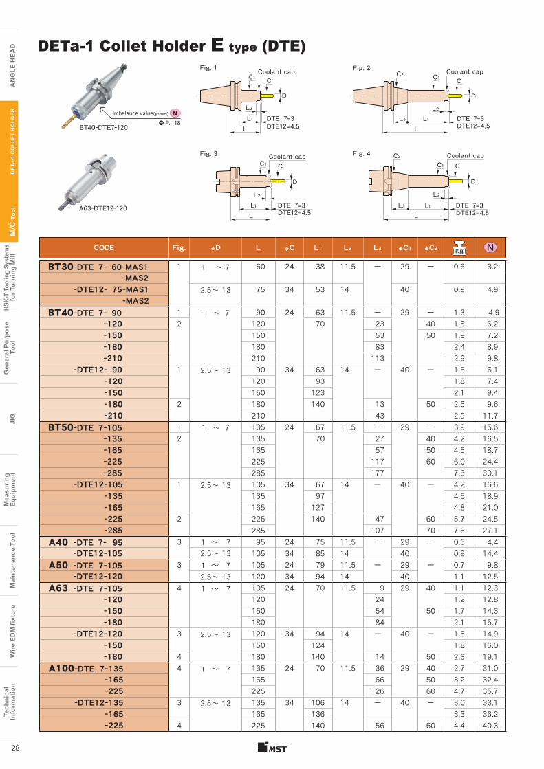
CODE Fig. φD L φC L1 L2 L3 φC1 φC2
BT30-DTE 7- 60-MAS1 1 1 〜 7 60 24 38 11.5 ー 29 ー 0.6 3.2 -MAS2
-DTE12- 75-MAS1 2.5〜 13 75 34 53 14 40 0.9 4.9 -MAS2
BT40-DTE 7- 90 1 1 〜 7 90 24 63 11.5 ー 29 ー 1.3 4.9-120 2 120 70 23 40 1.5 6.2 -150 150 53 50 1.9 7.2 -180 180 83 2.4 8.9 -210 210 113 2.9 9.8
-DTE12- 90 1 2.5〜 13 90 34 63 14 ー 40 ー 1.5 6.1 -120 120 93 1.8 7.4 -150 150 123 2.1 9.4 -180 2 180 140 13 50 2.5 9.6 -210 210 43 2.9 11.7
BT50-DTE 7-105 1 1 〜 7 105 24 67 11.5 ー 29 ー 3.9 15.6 -135 2 135 70 27 40 4.2 16.5 -165 165 57 50 4.6 18.7 -225 225 117 60 6.0 24.4 -285 285 177 7.3 30.1
-DTE12-105 1 2.5〜 13 105 34 67 14 ー 40 ー 4.2 16.6 -135 135 97 4.5 18.9 -165 165 127 4.8 21.0 -225 2 225 140 47 60 5.7 24.5 -285 285 107 70 7.6 27.1
A40 -DTE 7- 95 3 1 ~ 7 95 24 75 11.5 ー 29 ー 0.6 4.4 -DTE12-105 2.5〜 13 105 34 85 14 40 0.9 14.4
A50 -DTE 7-105 3 1 ~ 7 105 24 79 11.5 ー 29 ー 0.7 9.8-DTE12-120 2.5〜 13 120 34 94 14 40 1.1 12.5
A63 -DTE 7-105 4 1 ~ 7 105 24 70 11.5 9 29 40 1.1 12.3 -120 120 24 1.2 12.8 -150 150 54 50 1.7 14.3 -180 180 84 2.1 15.7
-DTE12-120 3 2.5〜 13 120 34 94 14 ー 40 ー 1.5 14.9 -150 150 124 1.8 16.0 -180 4 180 140 14 50 2.3 19.1
A100-DTE 7-135 4 1 ~ 7 135 24 70 11.5 36 29 40 2.7 31.0 -165 165 66 50 3.2 32.4 -225 225 126 60 4.7 35.7
-DTE12-135 3 2.5〜 13 135 34 106 14 ー 40 - 3.0 33.1 -165 165 136 3.3 36.2 -225 4 225 140 56 60 4.4 40.3
DETa-1 Collet Holder E type (DTE)
A63ーDTE12ー120
Coolant cap
Coolant cap
Coolant cap
Coolant cap
C1 C
D
L1
L3
L
C1
C2C1 C1
C
CC
D
DD
L1
L1L1L2L2
L2 L2L3
L
LL
DTE 7=3DTE12=4.5
DTE 7=3DTE12=4.5
DTE 7=3DTE12=4.5
DTE 7=3DTE12=4.5
C2
BT40ーDTE7ー120 P. 118N
Fig. 1 Fig. 2
Fig. 3 Fig. 4
Imbalance value(g・mm)
28
DE
Ta-1
CO
LLE
T H
OLD
ER
Tech
nica
lIn
form
atio
nW
ire
EDM
fixt
ure
Mai
nten
ance
Too
lM
easu
ring
Equi
pmen
tJI
GG
ener
al P
urpo
se T
ool
HSK-
T To
olin
g Sy
stem
sfo
r Tur
ning
Mill
M/C
Too
l
A
NG
LE H
EA
D
Tech
nica
lIn
form
atio
nW
ire
EDM
fixt
ure
Mai
nten
ance
Too
lM
easu
ring
Eq
uipm
ent
JIG
Gen
eral
Pur
pose
Too
lHS
K-T
Tool
ing
Syst
ems
for T
urni
ng M
illM
/C T
ool
AN
GLE
HE
AD
■Option●DETa-1 collet→P.31 ●Wrench→P.31 ●Retention knob ( BT40 / 50 )→P.64 ●Tap rod (DTE12) →P.30 ●Spacer ●Coolant cap ●Spacer set ●Coolant-through system
■Std. Access.●Coolant duct (Fixed)( HSK-A ) →P.104 ●Retention knob ( BT30 )
■Note● Swing type coolant ducts are available upon request(HSK-A).
For details, please contact us.■Caution
●A dedicated retention knob is supplied with the BT30-DTE as a standard accessory. When ordering, specify whether a MAS-1 or MAS-2 retention knob is required. To replace the retention knob, please contact us.●For precautions and maintenance, refer to page 115.
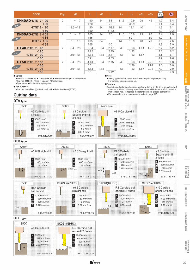
CODE Fig. φD L φC L1 L2 L3 φC1 φC2
DN40AD-DTE 7- 90 2 1 〜 7 90 24 58 11.5 12.9 29 45 1.2 5.4-120 120 70 30.9 1.4 6.4
-DTE12- 90 2.5〜13 90 34 58.8 14 12.1 40 1.3 6.1-150 150 118.8 1.9 9.3
DN50AD-DTE 7-105 2 1 〜 7 105 24 70 11.5 15.9 29 70 3.4 12.0-165 165 60 50 4.2 15.1
-DTE12-105 2.5〜13 105 34 14 15.9 40 70 3.6 12.6-165 165 130 4.2 17.0
CT40-DTE 7- 90 2 .04〜.28 3.54 .94 2.17 .45 .63 1.14 1.75 2.7 5.2-120 4.72 2.75 1.22 3.3 6.2
-DTE12- 90 .10〜.51 3.54 1.34 2.17 .55 .63 1.57 3.1 6.1-150 5.91 4.53 4.2 9.6
CT50-DTE 7-105 2 .04〜.28 4.13 .94 2.75 .45 .63 1.14 2.75 7.5 11.8-165 6.5 2.36 1.97 9.0 15.0
-DTE12-105 .10〜.51 4.13 1.34 .55 .63 1.57 2.75 7.9 12.9-165 6.5 5.12 9.3 17.3
DE
Ta-1
CO
LLE
T H
OLD
ER
29
Cutting data
BT40-DTB3-110L
min-1mm/minm/min
60006015
nVfVc
φ0.8 Straight drill
A63-DTB3-75
min-1mm/minm/min
1000040025
nVfVc
φ0.8 Straight drill
E32-DTA3-75
min-1mm/minm/minmm/rev
9000900850.1
nVfVcf
φ3 Carbide drill 3 flutes
S50C
E32-DTB3-65
R1.5 Carbide ball endmill
E32-DTB3-65
min-1mm/minm/minmm/t
600015060
0.013
nVfVcfz
φ3 Carbide Square endmill 2 flutes
S50C
E32-DTB3-65
R1.5 Carbide ball endmill
S50C
F63-DTB3-75
3715307
0.01
φ0.6 Carbide straight drill
STAVAX(42HRC)
BT40-DTB7-105
min-1mm/minm/minmm/t
50001500940.15
nVfVcfz
R3 Carbide ball endmill 2 flutes
SKD61(46HRC)
A63-DTE12-120
R5 Carbide ball endmill 2 flutes
SKD61(53HRC)
A63-DTE7-105
φ6 Carbide drillS50C
BT40-DTA12-165
φ8.5 Carbide drill
Aluminum
BT40-DTB12-90
min-1mm/minm/minmm/t
450015001410.17
nVfVcfz
φ10 Carbide endmill 2 flutes
SKD61(46HRC)
min-1mm/minm/minmm/rev
1250015601200.125
nVfVcf
min-1mm/minm/minmm/rev
1250015601200.125
nVfVcf
min-1mm/minm/minmm/rev
636915921200.25
nVfVcf
min-1mm/minm/minmm/rev
1000050002670.5
nVfVcf
min-1mm/minm/minmm/t
2000060006280.15
nVfVcfz
※234 pcs.
nVfVcf
min-1mm/minm/minmm/rev
DTA type
DTB type
DTE type
E32-DTA3-75
min-1mm/minm/minmm/t
600015060
0.013
nVfVcfz
φ3 Carbide Square endmill 3 flutes
S50C
DIN
DIN
CAT.
CAT.
A6061 A5052 S50CS50CS50CS50C
0.6 309
4 30.65
0.150.21
6
0.1511
0.4 0.20.2
18 0.5
Tech
nica
lIn
form
atio
nW
ire
EDM
fixt
ure
Mai
nten
ance
Too
lM
easu
ring
Equi
pmen
tJI
GG
ener
al P
urpo
se T
ool
HSK-
T To
olin
g Sy
stem
sfo
r Tur
ning
Mill
M/C
Too
l
A
NG
LE H
EA
D
Tech
nica
lIn
form
atio
nW
ire
EDM
fixt
ure
Mai
nten
ance
Too
lM
easu
ring
Eq
uipm
ent
JIG
Gen
eral
Pur
pose
Too
lHS
K-T
Tool
ing
Syst
ems
for T
urni
ng M
illM
/C T
ool
AN
GLE
HE
AD
Coolant cap
Spacer
DTE Holder
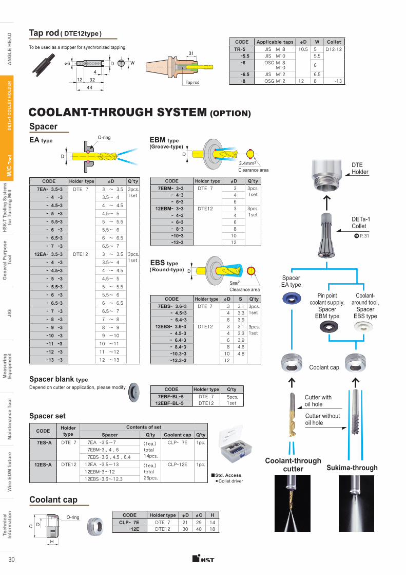
Spacer blank typeCODE Holder type Q’ty
7EBFーBLー5 DTE 7 5pcs. 1set12EBFーBLー5 DTE12
Spacer set
CODE Holder type
Contents of setSpacer Q’ty Coolant cap Q’ty
7ESーA DTE 7 7EA ー3.5〜7 (1ea.)total14pcs.
CLPー 7E 1pc. 7EBMー3 , 4 , 6 7EBS ー3.6 , 4.5 , 6.4
12ESーA DTE12 12EA ー3.5〜13 (1ea.)total26pcs.
CLPー12E 1pc.12EBMー3〜1212EBS ー3.6〜12.3
Depend on cutter or application, please modify.
CODE Holder type φD φC HCLPー 7E DTE 7 21 29 14
ー12E DTE12 30 40 18
EA type
CODE Holder type φD Q’ty7EBMー 3ー3 DTE 7 3 3pcs.
1setー 4ー3 4ー 6ー3 6
12EBMー 3ー3 DTE12 3 3pcs.1setー 4ー3 4
ー 6ー3 6ー 8ー3 8ー10ー3 10ー12ー3 12
CODE Holder type φD S Q’ty7EBSー 3.6ー3 DTE 7 3 3.1
ー 4.5ー3 4 3.3ー 6.4ー3 6 3.9
12EBSー 3.6ー3 DTE12 3 3.1ー 4.5ー3 4 3.3ー 6.4ー3 6 3.9ー 8.4ー3 8 4.6ー10.3ー3 10 4.8ー12.3ー3 12
CODE Holder type φD Q’ty7EAー 3.5ー3 DTE 7 3 〜 3.5
ー 4 ー3 3.5〜 4ー 4.5ー3 4 〜 4.5ー 5 ー3 4.5〜 5ー 5.5ー3 5 〜 5.5ー 6 ー3 5.5〜 6ー 6.5ー3 6 〜 6.5ー 7 ー3 6.5〜 7
12EAー 3.5ー3 DTE12 3 〜 3.5ー 4 ー3 3.5〜 4ー 4.5ー3 4 〜 4.5ー 5 ー3 4.5〜 5ー 5.5ー3 5 〜 5.5ー 6 ー3 5.5〜 6ー 6.5ー3 6 〜 6.5ー 7 ー3 6.5〜 7ー 8 ー3 7 〜 8ー 9 ー3 8 〜 9ー10 ー3 9 〜10ー11 ー3 10 〜11ー12 ー3 11 〜12ー13 ー3 12 〜13
EBM type
EBS type
O-ring
■Std. Access.●Collet driver
COOLANT-THROUGH SYSTEM (OPTION)
DETa-1 Collet
Coolant cap
Spacer EA type
Coolant- around tool,
Spacer EBS type
Pin point coolant supply,
Spacer EBM type
Cutter without oil hole
Cutter with oil hole
Coolant-through cutter Sukima-through
D D
C
H
D
O-ring
3pcs.1set
3pcs.1set
3pcs.1set
3pcs.1set
3.4mm2
S㎜2
Clearance area
Clearance area
D
P. 31
CODE Applicable taps φD W ColletTRー5 JIS M 8 10.5 5 D12-12
ー5.5 JIS M10 5.5ー6 OSG M 8
M10 6
ー6.5 JIS M12 6.5ー8 OSG M12 12 8 -13
To be used as a stopper for synchronized tapping.
Tap rod ( DTE12type )
44
D4
W
3212
φ6
(Groove-type)
( Round-type)
31
Tap rod
30
DE
Ta-1
CO
LLE
T H
OLD
ER
Tech
nica
lIn
form
atio
nW
ire
EDM
fixt
ure
Mai
nten
ance
Too
lM
easu
ring
Equi
pmen
tJI
GG
ener
al P
urpo
se T
ool
HSK-
T To
olin
g Sy
stem
sfo
r Tur
ning
Mill
M/C
Too
l
A
NG
LE H
EA
D
Tech
nica
lIn
form
atio
nW
ire
EDM
fixt
ure
Mai
nten
ance
Too
lM
easu
ring
Eq
uipm
ent
JIG
Gen
eral
Pur
pose
Too
lHS
K-T
Tool
ing
Syst
ems
for T
urni
ng M
illM
/C T
ool
AN
GLE
HE
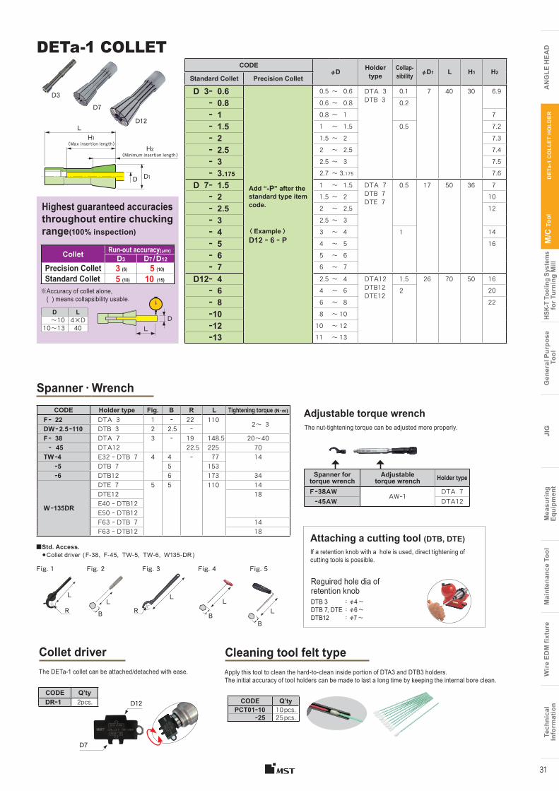
ADDETa-1 COLLET
D12
D7
CODEφD Holder
typeCollap-sibility φD1 L H1 H2
Standard Collet Precision Collet
D 3ー 0.6
Add “-P” after the standard type item code.
〈 Example 〉D12 ー 6 ー P
0.5 〜 0.6 DTA 3DTB 3
0.1 7 40 30 6.9ー 0.8 0.6 〜 0.8 0.2ー 1 0.8 〜 1 7
ー 1.5 1 〜 1.5 0.5 7.2
ー 2 1.5 〜 2 7.3
ー 2.5 2 〜 2.5 7.4
ー 3 2.5 〜 3 7.5ー 3.175 2.7 〜 3.175 7.6
D 7ー 1.5 1 〜 1.5 DTA 7DTB 7DTE 7
0.5 17 50 36 7ー 2 1.5 〜 2 10
ー 2.5 2 〜 2.5 12ー 3 2.5 〜 3
ー 4 3 〜 4 1 14
ー 5 4 〜 5 16ー 6 5 〜 6ー 7 6 〜 7
D12ー 4 2.5 〜 4 DTA12DTB12DTE12
1.5 26 70 50 16ー 6 4 〜 6 2 20
ー 8 6 〜 8 22ー10 8 〜 10
ー12 10 〜 12ー13 11 〜 13
D3
Collet Run-out accuracy(μm)
D3 D7 / D12
Precision ColletStandard Collet
Highest guaranteed accuracies throughout entire chucking range(100% inspection)
※ Accuracy of collet alone, ( ) means collapsibility usable.
3 (6)
10 (15)
5 (10)
5 (10)
LD
D L〜10 4×D
10〜13 40
Spanner ・ Wrench
Adjustable torque wrench
Collet driver Cleaning tool felt type
D12CODE Q’tyDRー1 2pcs.
The DETa-1 collet can be attached/detached with ease.
D7
CODE Q’tyPCT01ー10 10 pcs.
ー25 25 pcs.
Apply this tool to clean the hard-to-clean inside portion of DTA3 and DTB3 holders. The initial accuracy of tool holders can be made to last a long time by keeping the internal bore clean.
CODE Holder type Fig. B R L Tightening torque (N・m)
F ー 22 DTA 3 1 ー 22 110 2〜 3DW ー 2.5 ー110 DTB 3 2 2.5 ーF ー 38 DTA 7 3 ー 19 148.5 20〜40ー 45 DTA12 22.5 225 70
TW ー4 E32 ー DTB 7 4 4 ー 77 14 ー5 DTB 7 5 153 ー6 DTB12 6 173 34
W ー135DR
DTE 7 5 5 110 14DTE12 18E40 ー DTB12E50 ー DTB12F63 ー DTB 7 14F63 ー DTB12 18
If a retention knob with a hole is used, direct tightening of cutting tools is possible.
Attaching a cutting tool (DTB, DTE)
Reguired hole dia of retention knobDTB 3 : φ4 〜 DTB 7, DTE : φ6 〜 DTB12 : φ7 〜
Spanner for torque wrench
Adjustable torque wrench Holder type
F ー38AWAWー1
DTA 7 ー45AW DTA12
The nut-tightening torque can be adjusted more properly.
Fig. 3 Fig. 4Fig. 2Fig. 1 Fig. 5
L
R
LL
B L
B
RL
B
■Std. Access.●Collet driver ( F-38, F-45, TW-5, TW-6, W135-DR )
DE
Ta-1
CO
LLE
T H
OLD
ER
31
LH1
( Max insertion length )H2
( Minimum insertion length )
D D1
Tech
nica
lIn
form
atio
nW
ire
EDM
fixt
ure
Mai
nten
ance
Too
lM
easu
ring
Equi
pmen
tJI
GG
ener
al P
urpo
se T
ool
HSK-
T To
olin
g Sy
stem
sfo
r Tur
ning
Mill
M/C
Too
l
A
NG
LE H
EA
D
Tech
nica
lIn
form
atio
nW
ire
EDM
fixt
ure
Mai
nten
ance
Too
lM
easu
ring
Eq
uipm
ent
JIG
Gen
eral
Pur
pose
Too
lHS
K-T
Tool
ing
Syst
ems
for T
urni
ng M
illM
/C T
ool
AN
GLE
HE
AD
CO
LLE
T H
OLD
ER
32
Collet Run-out accuracy(μm)
Precision Collet 5Standard Collet 10
D L 〜10 4×D10 〜20 4020.5〜42 60
※Accuracy of collet alone
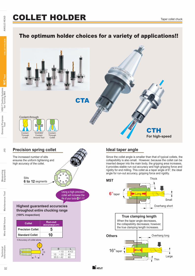
The increased number of slits ensures the uniform tightening and high accuracy of the collet.
Precision spring collet
Highest guaranteed accuracies throughout entire chucking range (100% inspection)
Ideal taper angle Since the collet angle is smaller than that of typical collets, the collapsibility is also small. However, because the collet can be inserted deeper into the main body, the gripping area increases, it provides stable run-out accuracy and high gripping force and rigidity for end milling. This collet as a taper angle of 6°, the ideal angle for run-out accuracy, gripping force and rigidity.
6 to 12 segments MST
6° taper
16° taper
Thick
Overhang long
Long
Small
When the taper angle decreases, the collapsibility decreases; however, the true clamping length increases.
True clamping length
LargeThin
Overhang short
Slits
Using a high-precision collet will increase the life of your tools.
L
D
P. 117
Others
Taper collet chuck
The optimum holder choices for a variety of applications!!
Coolant-through
Coolant-ThroughCutter
Coolant-Through
Collet
“SUKIMA” Coolant
Around Tool
CTHFor high-speed
CTA
Short
COLLET HOLDER
Tech
nica
lIn
form
atio
nW
ire
EDM
fixt
ure
Mai
nten
ance
Too
lM
easu
ring
Equi
pmen
tJI
GG
ener
al P
urpo
se T
ool
HSK-
T To
olin
g Sy
stem
sfo
r Tur
ning
Mill
M/C
Too
l
A
NG
LE H
EA
D
Tech
nica
lIn
form
atio
nW
ire
EDM
fixt
ure
Mai
nten
ance
Too
lM
easu
ring
Eq
uipm
ent
JIG
Gen
eral
Pur
pose
Too
lHS
K-T
Tool
ing
Syst
ems
for T
urni
ng M
illM
/C T
ool
AN
GLE
HE
AD
CO
LLE
T H
OLD
ER
33
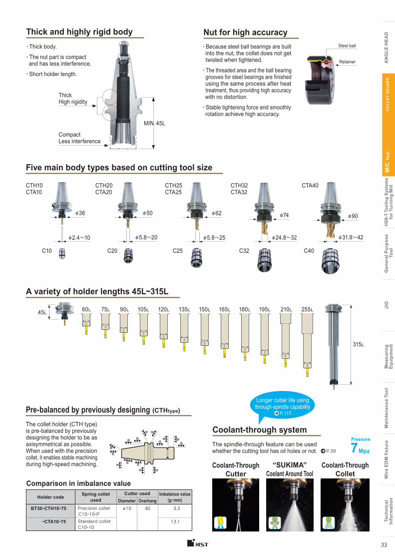
The collet holder (CTH type) is pre-balanced by previously designing the holder to be as axisymmetrical as possible. When used with the precision collet, it enables stable machining during high-speed machining.
Thick and highly rigid body
Five main body types based on cutting tool size
Coolant-Through Cutter
The spindle-through feature can be used whether the cutting tool has oil holes or not.
CTA40
φ90
CTH32 CTA32
φ74
CTH25 CTA25
φ62
CTH20 CTA20
φ50φ36
CTH10 CTA10
C10
φ2.4〜10
C25
φ5.8〜25
C32
φ24.8〜32
C40
φ31.8〜42
C20
φ5.8〜20
Longer cutter life using through-spindle capability
P. 117
P. 39
A variety of holder lengths 45L~315L
60L 255L195L180L165L150L135L120L105L90L75L 210L45L
315L
Pre-balanced by previously designing (CTHtype)
Coolant-through system
Holder code Spring collet used
Cutter used Imbalance value(g・mm)Diameter Overhang
BT30ーCTH10ー75 Precision collet C10ー10ーP
φ10 40 3.3
ーCTA10ー75 Standard colletC10ー10
13.1
Comparison in imbalance value
Thick High rigidity
Compact Less interference
Coolant-Through Collet
“SUKIMA” Coolant Around Tool
Nut for high accuracy ・ Because steel ball bearings are built into the nut, the collet does not get twisted when tightened.
・ The threaded area and the ball bearing grooves for steel bearings are finished using the same process after heat treatment, thus providing high accuracy with no distortion.
・ Stable tightening force and smoothly rotation achieve high accuracy.
・ Thick body.
・ The nut part is compact and has less interference.
・ Short holder length.
Retainer
Steel ball
7 Mpa
Pressure
MIN. 45L
CODE Fig. φD L φC L1
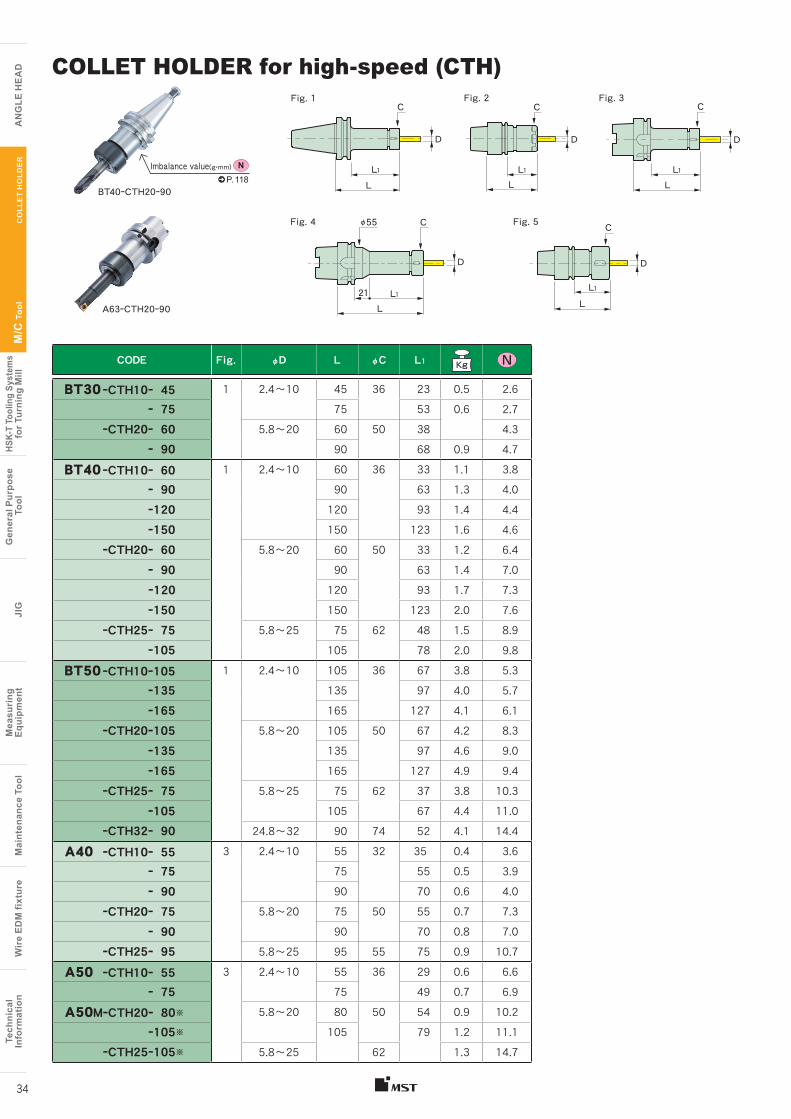
BT30 ーCTH10ー 45 1 2.4〜10 45 36 23 0.5 2.6ー 75 75 53 0.6 2.7
ーCTH20ー 60 5.8〜20 60 50 38 4.3ー 90 90 68 0.9 4.7
BT40 ーCTH10ー 60 1 2.4〜10 60 36 33 1.1 3.8ー 90 90 63 1.3 4.0ー120 120 93 1.4 4.4ー150 150 123 1.6 4.6
ーCTH20ー 60 5.8〜20 60 50 33 1.2 6.4ー 90 90 63 1.4 7.0ー120 120 93 1.7 7.3ー150 150 123 2.0 7.6
ーCTH25ー 75 5.8〜25 75 62 48 1.5 8.9ー105 105 78 2.0 9.8
BT50 ーCTH10ー105 1 2.4〜10 105 36 67 3.8 5.3ー135 135 97 4.0 5.7ー165 165 127 4.1 6.1
ーCTH20ー105 5.8〜20 105 50 67 4.2 8.3ー135 135 97 4.6 9.0ー165 165 127 4.9 9.4
ーCTH25ー 75 5.8〜25 75 62 37 3.8 10.3ー105 105 67 4.4 11.0
ーCTH32ー 90 24.8〜32 90 74 52 4.1 14.4A40 ーCTH10ー 55 3 2.4〜10 55 32 35 0.4 3.6
ー 75 75 55 0.5 3.9ー 90 90 70 0.6 4.0
ーCTH20ー 75 5.8〜20 75 50 55 0.7 7.3ー 90 90 70 0.8 7.0
ーCTH25ー 95 5.8〜25 95 55 75 0.9 10.7A50 ーCTH10ー 55 3 2.4〜10 55 36 29 0.6 6.6
ー 75 75 49 0.7 6.9A50MーCTH20ー 80※ 5.8〜20 80 50 54 0.9 10.2
ー105※ 105 79 1.2 11.1ーCTH25ー105※ 5.8〜25 62 1.3 14.7
COLLET HOLDER for high-speed (CTH)
Imbalance value(g・mm) NP. 118
A63ーCTH20ー90
Cφ55
C C
D
D D
L1
L1 L1L L
L21
C
D
L1L BT40ーCTH20ー90
Fig. 1 Fig. 2
Fig. 4
Fig. 3
Tech
nica
lIn
form
atio
nW
ire
EDM
fixt
ure
Mai
nten
ance
Too
lM
easu
ring
Equi
pmen
tJI
GG
ener
al P
urpo
se T
ool
HSK-
T To
olin
g Sy
stem
sfo
r Tur
ning
Mill
M/C
Too
l
A
NG
LE H
EA
D
Tech
nica
lIn
form
atio
nW
ire
EDM
fixt
ure
Mai
nten
ance
Too
lM
easu
ring
Eq
uipm
ent
JIG
Gen
eral
Pur
pose
Too
lHS
K-T
Tool
ing
Syst
ems
for T
urni
ng M
illM
/C T
ool
AN
GLE
HE
AD
CO
LLE
T H
OLD
ER
34
D
C
LL1
Fig. 5
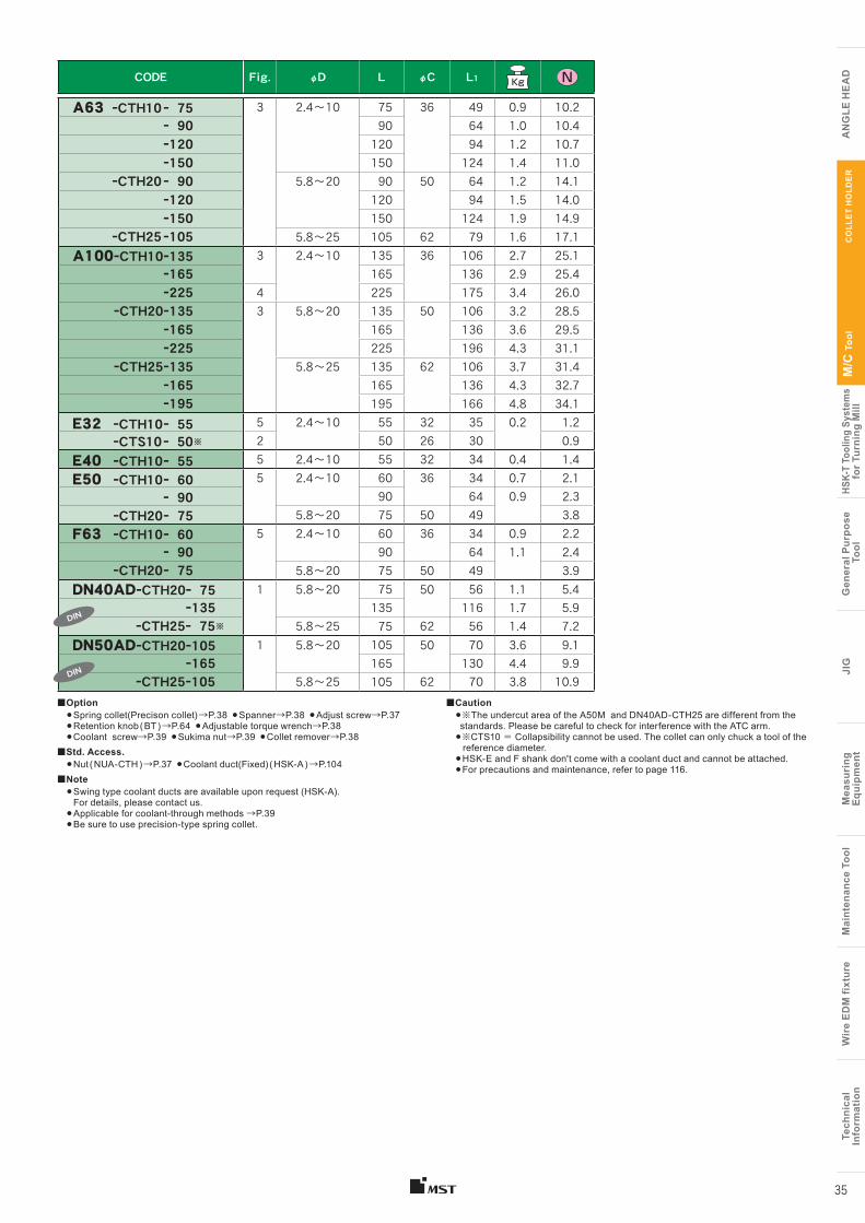
CODE Fig. φD L φC L1
A63 ーCTH10 ー 75 3 2.4〜10 75 36 49 0.9 10.2 ー 90 90 64 1.0 10.4 ー120 120 94 1.2 10.7 ー150 150 124 1.4 11.0
ーCTH20 ー 90 5.8〜20 90 50 64 1.2 14.1 ー120 120 94 1.5 14.0ー150 150 124 1.9 14.9
ーCTH25 ー105 5.8〜25 105 62 79 1.6 17.1 A100ーCTH10ー135 3 2.4〜10 135 36 106 2.7 25.1
ー165 165 136 2.9 25.4 ー225 4 225 175 3.4 26.0
ーCTH20ー135 3 5.8〜20 135 50 106 3.2 28.5 ー165 165 136 3.6 29.5 ー225 225 196 4.3 31.1
ーCTH25ー135 5.8〜25 135 62 106 3.7 31.4 ー165 165 136 4.3 32.7 ー195 195 166 4.8 34.1
E32 ーCTH10ー 55 5 2.4〜10 55 32 35 0.2 1.2ーCTS10 ー 50※ 2 50 26 30 0.9
E40 ーCTH10ー 55 5 2.4〜10 55 32 34 0.4 1.4E50 ーCTH10ー 60 5 2.4〜10 60 36 34 0.7 2.1
ー 90 90 64 0.9 2.3ーCTH20ー 75 5.8〜20 75 50 49 3.8
F63 ーCTH10ー 60 5 2.4〜10 60 36 34 0.9 2.2ー 90 90 64 1.1 2.4
ーCTH20ー 75 5.8〜20 75 50 49 3.9DN40ADーCTH20ー 75 1 5.8〜20 75 50 56 1.1 5.4 ー135 135 116 1.7 5.9 ーCTH25ー 75※ 5.8〜25 75 62 56 1.4 7.2DN50ADーCTH20ー105 1 5.8〜20 105 50 70 3.6 9.1 ー165 165 130 4.4 9.9 ーCTH25ー105 5.8〜25 105 62 70 3.8 10.9
■Option●Spring collet(Precison collet) →P.38 ●Spanner→P.38 ●Adjust screw→P.37●Retention knob ( BT ) →P.64 ●Adjustable torque wrench→P.38●Coolant screw→P.39 ●Sukima nut→P.39 ●Collet remover→P.38
■Std. Access.●Nut ( NUA-CTH ) →P.37 ●Coolant duct(Fixed) ( HSK-A ) →P.104
■Note● Swing type coolant ducts are available upon request (HSK-A).
For details, please contact us.●Applicable for coolant-through methods →P.39●Be sure to use precision-type spring collet.
■Caution●※The undercut area of the A50M and DN40AD-CTH25 are different from the standards. Please be careful to check for interference with the ATC arm.●※CTS10 = Collapsibility cannot be used. The collet can only chuck a tool of the reference diameter.●HSK-E and F shank don't come with a coolant duct and cannot be attached. ●For precautions and maintenance, refer to page 116.
Tech
nica
lIn
form
atio
nW
ire
EDM
fixt
ure
Mai
nten
ance
Too
lM
easu
ring
Equi
pmen
tJI
GG
ener
al P
urpo
se T
ool
HSK-
T To
olin
g Sy
stem
sfo
r Tur
ning
Mill
M/C
Too
l
A
NG
LE H
EA
D
Tech
nica
lIn
form
atio
nW
ire
EDM
fixt
ure
Mai
nten
ance
Too
lM
easu
ring
Eq
uipm
ent
JIG
Gen
eral
Pur
pose
Too
lHS
K-T
Tool
ing
Syst
ems
for T
urni
ng M
illM
/C T
ool
AN
GLE
HE
AD
CO
LLE
T H
OLD
ER
35
DIN
DIN
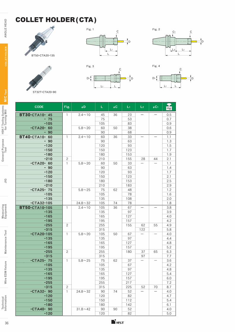
CODE Fig. φD L φC L1 L2 φC1 Kg
BT30ーCTA10ー 45 1 2.4〜10 45 36 23 ー ー 0.5 ー 75 75 53 0.7 ー105 105 83 0.9
ーCTA20ー 60 5.8〜20 60 50 38 0.6 ー 90 90 68 0.9
BT40ーCTA10ー 60 1 2.4〜10 60 36 33 ー ー 1.1 ー 90 90 63 1.3 ー120 120 93 1.5 ー150 150 123 1.7 ー180 180 153 1.9 ー210 2 210 155 28 44 2.1
ーCTA20ー 60 1 5.8〜20 60 50 33 ー ー 1.1 ー 90 90 63 1.4 ー120 120 93 1.7 ー150 150 123 2.1 ー180 180 153 2.5 ー210 210 183 2.9
ーCTA25ー 75 5.8〜25 75 62 48 1.2 ー105 105 78 1.6 ー135 135 108 2.0
ーCTA32ー105 24.8〜32 105 74 78 1.8 BT50ーCTA10ー105 1 2.4〜10 105 36 67 ー ー 3.8
ー135 135 97 3.9 ー165 165 127 4.0 ー195 195 157 4.2 ー255 2 255 155 62 55 4.9 ー315 315 122 5.8
ーCTA20ー105 1 5.8〜20 105 50 67 ー ー 4.0 ー135 135 97 4.4 ー165 165 127 4.8 ー195 195 157 5.2 ー255 2 255 180 37 65 6.3 ー315 315 97 7.7
ーCTA25ー 75 1 5.8〜25 75 62 37 ー ー 3.6 ー105 105 67 4.2 ー135 135 97 4.8 ー165 165 127 5.4 ー195 195 157 6.0 ー255 255 217 7.2 ー315 2 315 225 52 70 8.7
ーCTA32ー 90 1 24.8〜32 90 74 52 ー ー 4.0 ー120 120 82 4.7 ー150 150 112 5.4 ー180 180 142 6.1
ーCTA40ー 90 31.8〜42 90 90 52 4.0 ー120 120 82 5.0
COLLET HOLDER ( CTA )
C
DD1
L1 L
Fig. 3C
D
L1
D1
L
Fig. 4
C
D
L1L
Fig. 1
ST32TーCTA20ー90
BT50ーCTA20ー135
Fig. 2C1 C
D
L1L
L2
Tech
nica
lIn
form
atio
nW
ire
EDM
fixt
ure
Mai
nten
ance
Too
lM
easu
ring
Equi
pmen
tJI
GG
ener
al P
urpo
se T
ool
HSK-
T To
olin
g Sy
stem
sfo
r Tur
ning
Mill
M/C
Too
l
A
NG
LE H
EA
D
Tech
nica
lIn
form
atio
nW
ire
EDM
fixt
ure
Mai
nten
ance
Too
lM
easu
ring
Eq
uipm
ent
JIG
Gen
eral
Pur
pose
Too
lHS
K-T
Tool
ing
Syst
ems
for T
urni
ng M
illM
/C T
ool
AN
GLE
HE
AD
CO
LLE
T H
OLD
ER
36
CODE Fig. L φD L1 J K G Holder typeAJCーM14 1 22 10 8 1.5 3 M14×1.5 CTA10
ST25T-CTA20
ーM24 27 20 13 5 4 M24×1.5 CTA20 (※1)BT40-CTA25- 75BT40-CTA32-105
ーM28 25 M28×1.5 CTA25 (※2)ーM18 24 15 8 M18×1.5 BT30-CTA20 ,
ST32T-CTA20
ーM18L 2 43 23 BT50-CTA32 , CTA40※1 : Except BT30, SE30M, ST25T and ST32T ※2 : Except BT40−CTA25−75
Nut Adjust screw
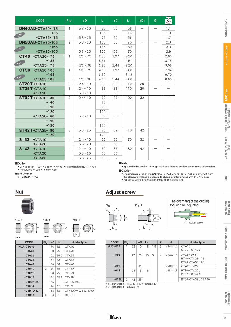
CODE Fig. φD L φC L1 φD1 G
DN40ADーCTA20ー 75 1 5.8〜20 75 50 56 ー ー 1.1 ー135 135 116 1.9 ーCTA25ー 75 5.8〜25 75 62 56 1.7 DN50ADーCTA20ー105 2 5.8〜20 105 50 70 ー ー 2.3 ー165 165 130 3.0 ーCTA25ー105 5.8〜25 105 62 70 2.9 CT40 ーCTA20ー 75 1 .23〜.79 2.95 1.97 2.20 ー ー 2.65 ー135 5.31 4.57 3.75 ーCTA25ー 75 .23〜.98 2.95 2.44 2.20 3.09CT50 ーCTA20ー105 1 .23〜.79 4.13 1.97 2.68 7.94 ー165 6.50 5.12 9.70 ーCTA25ー105 .23〜.98 4.13 2.44 2.68 8.60ST20TーCTA10 3 2.4〜10 35 36 110 20 ー ーST25TーCTA10 3 2.4〜10 35 36 110 25 ー ー
ーCTA20 5.8〜20 60 50ST32TーCTA10ー 30 3 2.4〜10 30 36 100 32 ー ー ー 60 60 ー 90 90 ー120 120 ーCTA20ー 60 5.8〜20 60 50 ー 90 90 ー120 120ST42TーCTA25ー 90 3 5.8〜25 90 62 110 42 ー ー ー120 120S 32 ーCTA10 4 2.4〜10 30 36 70 32 ー ー
ーCTA20 5.8〜20 60 50S 42 ーCTA10 4 2.4〜10 30 36 80 42 ー ー
ーCTA20 5.8〜20 35 50 ーCTA25 5.8〜25 80 62
■Option●Spring collet→P.38 ●Spanner→P.38 ●Retention knob(BT) →P.64 ●Adjustable torque wrench→P.38
■Std. Access.●Nut ( NUA-CTA )
■Note●Applicable for coolant-through methods. Please contact us for more information.
■Caution●The undercut area of the DN40AD-CTA25 and CT40-CTA25 are different from the standard. Please be careful to check for interference with the ATC arm.●For precautions and maintenance, refer to page 116.
CODE Fig. φC H Holder typeNUAーCTA10 1 36 18 CTA10
ーCTA20 50 25 CTA20ーCTA25 62 28.5 CTA25ーCTA32 74 32 CTA32ーCTA40 90 36 CTA40ーCTH10 2 36 18 CTH10ーCTH20 50 25 CTH20ーCTH25 62 28.5 CTH25ーCTH25ー55 55 CTH25 (A40)ーCTH32 74 32 CTH32ーCTH10ー32 32 18 CTH10 (A40, E32, E40)ーCTS10 3 26 21 CTS10
HHH
C CC
Fig. 1 Fig. 2 Fig. 3
Fig. 1 Fig. 2K K
GG
JJ DD
L1L1L L
Tech
nica
lIn
form
atio
nW
ire
EDM
fixt
ure
Mai
nten
ance
Too
lM
easu
ring
Equi
pmen
tJI
GG
ener
al P
urpo
se T
ool
HSK-
T To
olin
g Sy
stem
sfo
r Tur
ning
Mill
M/C
Too
l
A
NG
LE H
EA
D
Tech
nica
lIn
form
atio
nW
ire
EDM
fixt
ure
Mai
nten
ance
Too
lM
easu
ring
Eq
uipm
ent
JIG
Gen
eral
Pur
pose
Too
lHS
K-T
Tool
ing
Syst
ems
for T
urni
ng M
illM
/C T
ool
AN
GLE
HE
AD
CO
LLE
T H
OLD
ER
37
DIN
DIN
CAT.
CAT.
The overhang of the cutting tool can be adjusted.
Adjust screw
CODEφD Holder
typeCollapsi-
bility L φD1 HStandard Collet
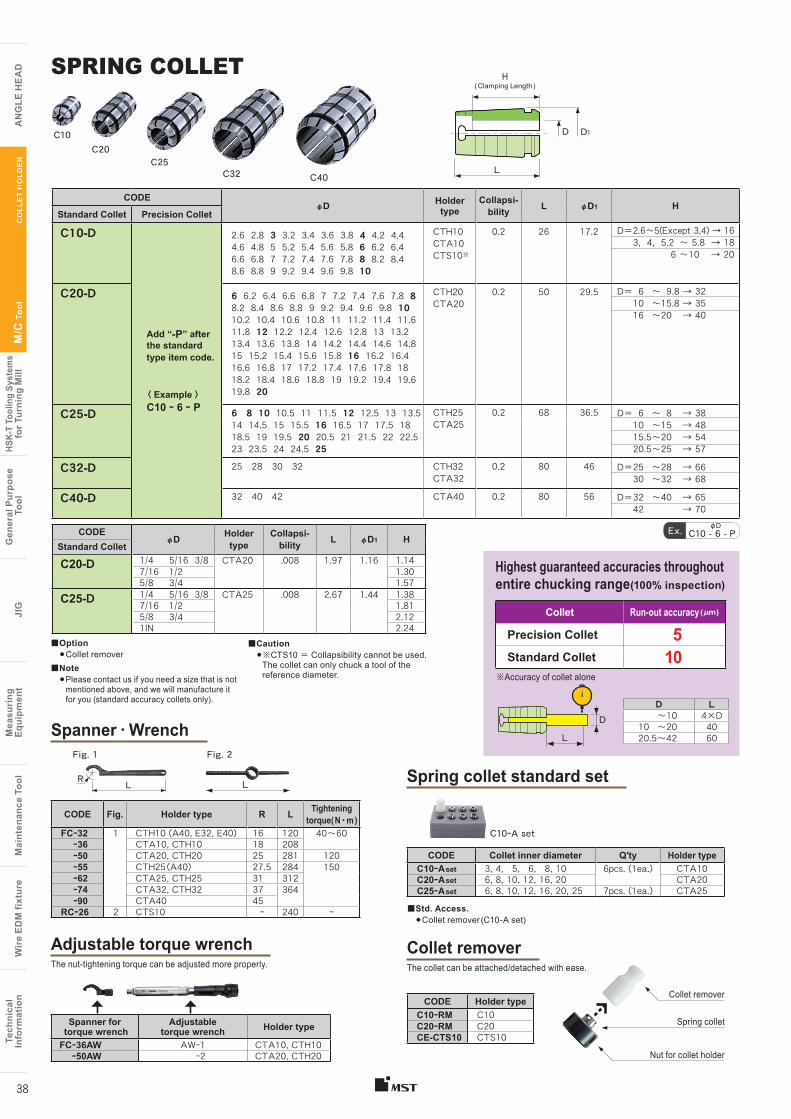
C20-D 1/4 5/16 3/8 CTA20 .008 1.97 1.16 1.147/16 1/2 1.305/8 3/4 1.57
C25-D 1/4 5/16 3/8 CTA25 .008 2.67 1.44 1.387/16 1/2 1.815/8 3/4 2.121IN 2.24
CODEφD Holder
typeCollapsi-
bility L φD1 HStandard Collet Precision Collet
C10-D
Add “-P” after the standard type item code.
〈 Example 〉C10 ー 6 ー P
2.6 2.8 3 3.2 3.4 3.6 3.8 4 4.2 4.4 4.6 4.8 5 5.2 5.4 5.6 5.8 6 6.2 6.4 6.6 6.8 7 7.2 7.4 7.6 7.8 8 8.2 8.4 8.6 8.8 9 9.2 9.4 9.6 9.8 10
CTH10CTA10CTS10※
0.2 26 17.2 D=2.6〜5(Except 3,4) → 16 3, 4, 5.2 〜 5.8 → 18
6 〜10 → 20
C20-D 6 6.2 6.4 6.6 6.8 7 7.2 7.4 7.6 7.8 8 8.2 8.4 8.6 8.8 9 9.2 9.4 9.6 9.8 10 10.2 10.4 10.6 10.8 11 11.2 11.4 11.6 11.8 12 12.2 12.4 12.6 12.8 13 13.2 13.4 13.6 13.8 14 14.2 14.4 14.6 14.8 15 15.2 15.4 15.6 15.8 16 16.2 16.4 16.6 16.8 17 17.2 17.4 17.6 17.8 18 18.2 18.4 18.6 18.8 19 19.2 19.4 19.6 19.8 20
CTH20CTA20
0.2 50 29.5 D= 6 〜 9.8 → 3210 〜15.8 → 3516 〜20 → 40
C25-D 6 8 10 10.5 11 11.5 12 12.5 13 13.5 14 14.5 15 15.5 16 16.5 17 17.5 18 18.5 19 19.5 20 20.5 21 21.5 22 22.5 23 23.5 24 24.5 25
CTH25CTA25
0.2 68 36.5 D= 6 〜 8 → 3810 〜15 → 4815.5〜20 → 5420.5〜25 → 57
C32-D 25 28 30 32 CTH32CTA32
0.2 80 46 D=25 〜28 → 6630 〜32 → 68
C40-D 32 40 42 CTA40 0.2 80 56 D=32 〜40 → 6542 → 70
Tech
nica
lIn
form
atio
nW
ire
EDM
fixt
ure
Mai
nten
ance
Too
lM
easu
ring
Equi
pmen
tJI
GG
ener
al P
urpo
se T
ool
HSK-
T To
olin
g Sy
stem
sfo
r Tur
ning
Mill
M/C
Too
l
A
NG
LE H
EA
D
Tech
nica
lIn
form
atio
nW
ire
EDM
fixt
ure
Mai
nten
ance
Too
lM
easu
ring
Eq
uipm
ent
JIG
Gen
eral
Pur
pose
Too
lHS
K-T
Tool
ing
Syst
ems
for T
urni
ng M
illM
/C T
ool
AN
GLE
HE
AD
CO
LLE
T H
OLD
ER
38
Nut for collet holder
Spring collet
Collet remover
Collet Run-out accuracy (μm)
Precision Collet
Standard Collet
D L 〜10 4×D10 〜20 4020.5〜42 60
※Accuracy of collet alone
105
Fig. 2Fig. 1
SPRING COLLET H ( Clamping Length )
D D1
L
D
L
C10C20
C25C32 C40
CODE Collet inner diameter Q'ty Holder typeC10ーA set 3, 4, 5, 6, 8, 10 6pcs. (1ea.) CTA10C20ーA set 6, 8, 10, 12, 16, 20 CTA20C25ーA set 6, 8, 10, 12, 16, 20, 25 7pcs. (1ea.) CTA25
C10ーA set
CODE Fig. Holder type R L Tightening torque( N ・ m )
FCー32 1 CTH10 (A40, E32, E40) 16 120 40〜60ー36 CTA10, CTH10 18 208ー50 CTA20, CTH20 25 281 120ー55 CTH25 (A40) 27.5 284 150ー62 CTA25, CTH25 31 312ー74 CTA32, CTH32 37 364ー90 CTA40 45
RCー26 2 CTS10 ー 240 ー
CODE Holder typeC10ーRM C10C20ーRM C20CE-CTS10 CTS10
The nut-tightening torque can be adjusted more properly.
Spanner for torque wrench
Adjustable torque wrench Holder type
FCー36AW AWー1 CTA10, CTH10ー50AW ー2 CTA20, CTH20
LR
The collet can be attached/detached with ease.
■Option●Collet remover
■Note● Please contact us if you need a size that is not
mentioned above, and we will manufacture it for you (standard accuracy collets only).
■Std. Access.●Collet remover (C10-A set)
Spring collet standard set
Collet remover
Spanner ・ Wrench
Adjustable torque wrench
L
φDEx. C10 - 6 - P
Highest guaranteed accuracies throughout entire chucking range(100% inspection)
■Caution● ※CTS10 = Collapsibility cannot be used.
The collet can only chuck a tool of the reference diameter.
d (Cutter shank)L S mm2Clearance area
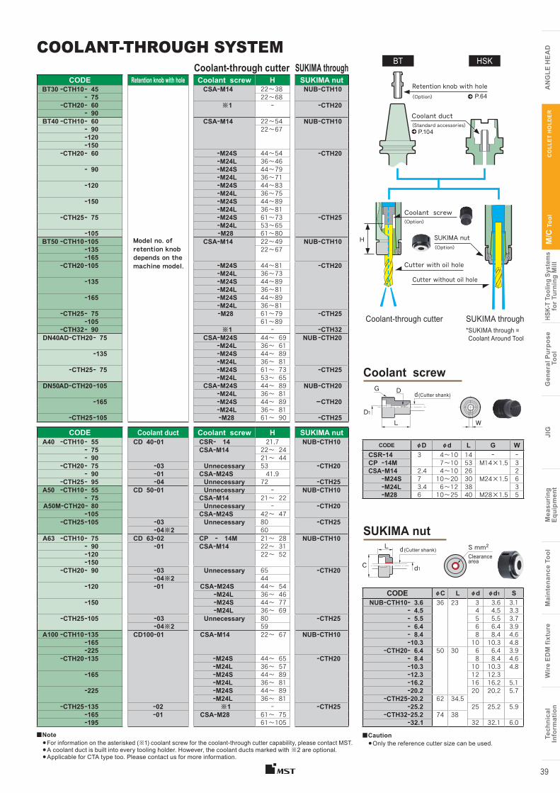
COOLANT-THROUGH SYSTEMCoolant-through cutter SUKIMA through
CODE Retention knob with hole Coolant screw H SUKIMA nutBT30 ーCTH10ー 45
Model no. of retention knob depends on the machine model.
CSAーM14 22〜38 NUBーCTH10ー 75 22〜68
ーCTH20ー 60 ※1 ー ーCTH20ー 90
BT40 ーCTH10ー 60 CSAーM14 22〜54 NUBーCTH10ー 90 22〜67ー120ー150
ーCTH20ー 60 ーM24S 44〜54 ーCTH20 ーM24L 36〜46
ー 90 ーM24S 44〜79 ーM24L 36〜71
ー120 ーM24S 44〜83 ーM24L 36〜75
ー150 ーM24S 44〜89 ーM24L 36〜81
ーCTH25ー 75 ーM24S 61〜73 ーCTH25 ーM24L 53〜65
ー105 ーM28 61〜80BT50 ーCTH10ー105 CSAーM14 22〜49 NUBーCTH10
ー135 22〜67ー165
ーCTH20ー105 ーM24S 44〜81 ーCTH20 ーM24L 36〜73
ー135 ーM24S 44〜89 ーM24L 36〜81
ー165 ーM24S 44〜89 ーM24L 36〜81
ーCTH25ー 75 ーM28 61〜79 ーCTH25ー105 61〜89
ーCTH32ー 90 ※1 ー ーCTH32DN40ADーCTH20ー 75 CSAーM24S 44〜 69 NUB ーCTH20
ーM24L 36〜 61ー135 ーM24S 44〜 89
ーM24L 36〜 81ーCTH25ー 75 ーM24S 61〜 73 ーCTH25
ーM24L 53〜 65DN50ADーCTH20ー105 CSAーM24S 44〜 89 NUBーCTH20
ーM24L 36〜 81ー165 ーM24S 44〜 89 ーCTH20
ーM24L 36〜 81ーCTH25ー105 ーM28 61〜 90 ーCTH25
CODE Coolant duct Coolant screw H SUKIMA nutA40 ーCTH10ー 55 CD 40ー01 CSRー 14 21.7 NUBーCTH10
ー 75 CSAーM14 22〜 24 ー 90 21〜 44
ーCTH20ー 75 ー03 Unnecessary 53 ーCTH20ー 90 ー01 CSAーM24S 41.9
ーCTH25ー 95 ー04 Unnecessary 72 ーCTH25A50 ーCTH10ー 55 CD 50ー01 Unnecessary ー NUBーCTH10
ー 75 CSAーM14 21〜 22 A50MーCTH20ー 80 Unnecessary ー ーCTH20
ー105 CSAーM24S 42〜 47 ーCTH25ー105 ー03 Unnecessary 80 ーCTH25
ー04※2 60A63 ーCTH10ー 75 CD 63ー02 CP ー 14M 21〜 28 NUBーCTH10
ー 90 ー01 CSAーM14 22〜 31 ー120 22〜 52ー150
ーCTH20ー 90 ー03 Unnecessary 65 ーCTH20ー04※2 44
ー120 ー01 CSAーM24S 44〜 54 ーM24L 36〜 46
ー150 ーM24S 44〜 77 ーM24L 36〜 69
ーCTH25ー105 ー03 Unnecessary 80 ーCTH25ー04※2 59
A100 ーCTH10ー135 CD100ー01 CSAーM14 22〜 67 NUBーCTH10ー165ー225
ーCTH20ー135 ーM24S 44〜 65 ーCTH20 ーM24L 36〜 57
ー165 ーM24S 44〜 89 ーM24L 36〜 81
ー225 ーM24S 44〜 89 ーM24L 36〜 81
ーCTH25ー135 ー02 ※1 ー ーCTH25ー165 ー01 CSAーM28 61〜 75ー195 61〜105
■Note●For information on the asterisked (※1) coolant screw for the coolant-through cutter capability, please contact MST.●A coolant duct is built into every tooling holder. However, the coolant ducts marked with ※2 are optional.●Applicable for CTA type too. Please contact us for more information.
■Caution●Only the reference cutter size can be used.
Tech
nica
lIn
form
atio
nW
ire
EDM
fixt
ure
Mai
nten
ance
Too
lM
easu
ring
Equi
pmen
tJI
GG
ener
al P
urpo
se T
ool
HSK-
T To
olin
g Sy
stem
sfo
r Tur
ning
Mill
M/C
Too
l
A
NG
LE H
EA
D
Tech
nica
lIn
form
atio
nW
ire
EDM
fixt
ure
Mai
nten
ance
Too
lM
easu
ring
Eq
uipm
ent
JIG
Gen
eral
Pur
pose
Too
lHS
K-T
Tool
ing
Syst
ems
for T
urni
ng M
illM
/C T
ool
AN
GLE
HE
AD
CO
LLE
T H
OLD
ER
39
CODE φC L φd φd1 SNUBーCTH10ー 3.6 36 23 3 3.6 3.1
ー 4.5 4 4.5 3.3ー 5.5 5 5.5 3.7ー 6.4 6 6.4 3.9ー 8.4 8 8.4 4.6ー10.3 10 10.3 4.8
ーCTH20ー 6.4 50 30 6 6.4 3.9ー 8.4 8 8.4 4.6ー10.3 10 10.3 4.8ー12.3 12 12.3ー16.2 16 16.2 5.1ー20.2 20 20.2 5.7
ーCTH25ー20.2 62 34.5ー25.2 25 25.2 5.9
ーCTH32ー25.2 74 38ー 32.1 32 32.1 6.0
CODE φD φd L G WCSRー14 3 4〜10 14 ー ーCP ー14M 7〜10 53 M14×1.5 3CSAーM14 2.4 4〜10 26 2
ーM24S 7 10〜20 30 M24×1.5 6ーM24L 3.4 6〜12 38 3ーM28 6 10〜25 40 M28×1.5 5
Coolant screw
Retention knob with hole
Coolant duct
(Option)
Cutter without oil hole
Cutter with oil hole
Coolant-through cutter
BT HSK
(Option)
SUKIMA nut
Gd (Cutter shank)
D
D1L
C d1
SUKIMA through* SUKIMA through = Coolant Around Tool
P.64
(Standard accessories)
(Option)
P.104
H
W
Coolant screw
SUKIMA nut
Tech
nica
lIn
form
atio
nW
ire
EDM
fixt
ure
Mai
nten
ance
Too
lM
easu
ring
Equi
pmen
tJI
GG
ener
al P
urpo
se T
ool
HSK-
T To
olin
g Sy
stem
sfo
r Tur
ning
Mill
M/C
Too
l
A
NG
LE H
EA
D
Tech
nica
lIn
form
atio
nW
ire
EDM
fixt
ure
Mai
nten
ance
Too
lM
easu
ring
Eq
uipm
ent
JIG
Gen
eral
Pur
pose
Too
lHS
K-T
Tool
ing
Syst
ems
for T
urni
ng M
illM
/C T
ool
AN
GLE
HE
AD
Hi-
AR
T M
ILLI
NG
CH
UC
K
40
Memory line
Before tightening
After tightening
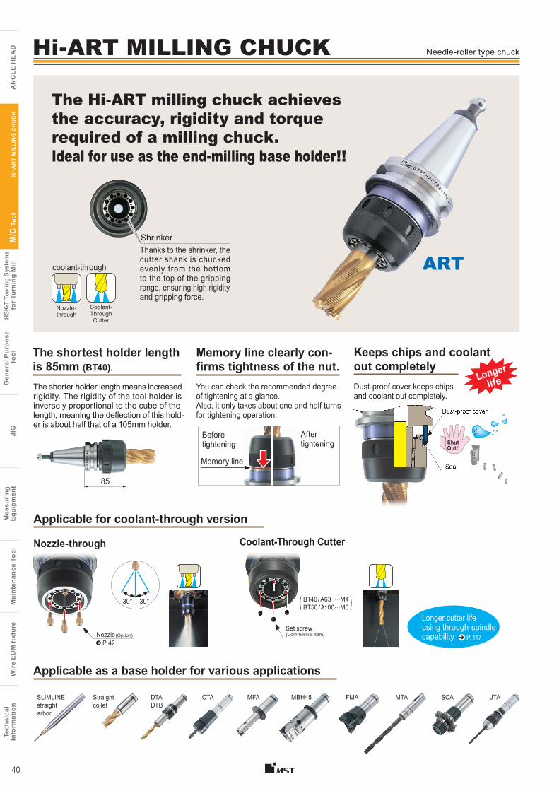
The Hi-ART milling chuck achieves the accuracy, rigidity and torque required of a milling chuck. Ideal for use as the end-milling base holder!!
Applicable as a base holder for various applications
85
Needle-roller type chuck
ShutOut!!
ARTcoolant-through
DTADTB
Straight collet
SLIMLINE straight arbor
CTA MFA MBH45
( )BT40 / A63 …M4 BT50 / A100…M6
30° 30°
Set screw (Commercial item)
Applicable for coolant-through version
Nozzle-through Coolant-Through Cutter
Seal
Dust-proof cover
You can check the recommended degree of tightening at a glance. Also, it only takes about one and half turns for tightening operation.
Memory line clearly con-firms tightness of the nut.
The shortest holder length is 85mm (BT40). The shorter holder length means increased rigidity. The rigidity of the tool holder is inversely proportional to the cube of the length, meaning the deflection of this hold-er is about half that of a 105mm holder.
Keeps chips and coolant out completely
Longer lifeDust-proof cover keeps chips
and coolant out completely.
Longer cutter life using through-spindle capability P. 117
Thanks to the shrinker, the cutter shank is chucked evenly from the bottom to the top of the gripping range, ensuring high rigidity and gripping force.
Shrinker
FMA MTA SCA JTA
Nozzle (Option)
P. 42
Coolant-ThroughCutter
Nozzle-through
Hi-ART MILLING CHUCK
CODE Fig. φD L φC L1Cutter insertion
length KgMAX.min-1
BT40ーART32 ー 85 1 32 85 72 37 66〜 88 1.9 6,000ー 95 95 47 2.1ー105 105 57 2.3ー135 135 87 3.0
BT50ーART32 ー105 2 32 105 82 ー 66〜 98 5.1 5,000ー135 135 6.4 ー165 165 7.7 ー180 180 8.4
ーART42 ー105 42 105 97 76〜108 5.4 3,000ー135 135 7.1
A50MーART32ー100 3 32 100 72 44 66〜 71 1.7 6,000A63 ーART32ー100 3 32 100 72 44 66〜 71 2.0 6,000A100ーART32ー135 4 32 135 82 ー 66〜 98 5.3 5,000
ーART42ー135 42 97 76〜 98 6.1 3,000
Hi-ART MILLING CHUCK (ART)
Fig. 4
C
A100ーART32ー135
Fig. 2Fig. 1
BT50ーART32ー105
Fig. 3 C C
C
L L
LL
D D
DD
L1
L1
Dust-proof cover
Dust-proof cover
Tech
nica
lIn
form
atio
nW
ire
EDM
fixt
ure
Mai
nten
ance
Too
lM
easu
ring
Equi
pmen
tJI
GG
ener
al P
urpo
se T
ool
HSK-
T To
olin
g Sy
stem
sfo
r Tur
ning
Mill
M/C
Too
l
A
NG
LE H
EA
D
Tech
nica
lIn
form
atio
nW
ire
EDM
fixt
ure
Mai
nten
ance
Too
lM
easu
ring
Eq
uipm
ent
JIG
Gen
eral
Pur
pose
Too
lHS
K-T
Tool
ing
Syst
ems
for T
urni
ng M
illM
/C T
ool
AN
GLE
HE
AD
Hi-
AR
T M
ILLI
NG
CH
UC
K
41
For face milling applications, combining a holder and a face mill arbor, with backup screw (ST32B, ST42B-FMA), will achieve strong gripping (Face Lock) and improve the rigidity during transverse feed milling.
Increased rigidity with the Face Lock system (BT)
Face Lock
Backup screwST32B / 42BFace mill arbor
■Option●Straight collet→P.42 ●Nozzle→P.42 ●Spanner with ejection hook→P.42●Adjust screw→P.42 ●Retention knob(BT)→P.64
■Std. Access.●Coolant duct (Fixed)( HSK-A ) →P.104
■Note●To utilize the coolant-through nozzle capability, the retention knob with hole and nozzle are required.● Swing type coolant ducts are available upon request(HSK-A).
For details, please contact us.
■Caution●For BT40 type, the outer diameter of the nut is larger than that of the V-flange. Therefore, pay close attention to possible interference with the ATC arm.●When using the straight arbor in BT40, use the S type (ex.S32-CTA10).●For A50M and A63, the coolant-through system is not available for straight collets.●Cutter-through coolant is not available for straight collets.●For precautions and maintenance, refer to page 116.
Tech
nica
lIn
form
atio
nW
ire
EDM
fixt
ure
Mai
nten
ance
Too
lM
easu
ring
Equi
pmen
tJI
GG
ener
al P
urpo
se T
ool
HSK-
T To
olin
g Sy
stem
sfo
r Tur
ning
Mill
M/C
Too
l
A
NG
LE H
EA
D
Tech
nica
lIn
form
atio
nW
ire
EDM
fixt
ure
Mai
nten
ance
Too
lM
easu
ring
Eq
uipm
ent
JIG
Gen
eral
Pur
pose
Too
lHS
K-T
Tool
ing
Syst
ems
for T
urni
ng M
illM
/C T
ool
AN
GLE
HE
AD
Spanner with ejection hook Nozzle
Straight collet
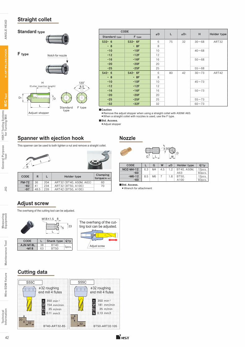
F type Notch for nozzle
CODEφD L φD1 H Holder type
Standard type F type
S32ー 6 S32ー 6F 6 75 32 30〜68 ART32ー 8 ー 8F 8ー10 ー10F 10 40〜68ー12 ー12F 12ー16 ー16F 16 50〜68ー20 ー20F 20ー25 ー25F 25 55〜68
S42ー 6 S42ー 6F 6 80 42 30〜73 ART42ー 8 ー 8F 8ー10 ー10F 10 45〜73ー12 ー12F 12ー16 ー16F 16 50〜73ー20 ー20F 20ー25 ー25F 25 55〜73ー32 ー32F 32 60〜73
Standard type
Standard type
F typeAdjust stopper
CODE R L Holder type Clamping torque( N・ m )
FMー72 36 204 ART32 ( BT40, A50M, A63 ) 60 ー82 41 234 ART32 ( BT50, A100 ) 70ー97 48.5 239 ART42 ( BT50, A100 )
This spanner can be used to both tighten a nut and remove a straight collet.
G
H(Cutter insertion length)
D1
L
D
120°8.5
L WD
±30°
■Std. Access.● Wrench for attachment
Cutting data
BT50-ART32-105
min-1
mm/minm/minmm/t
35018135
0.13
nVfVcfz
φ32 roughing end mill 4 flutes
S55C
BT40-ART32-85
min-1
mm/minm/minmm/t
35015435
0.11
nVfVcfz
φ32 roughing end mill 4 flutes
S55C
Adjust screw The overhang of the cutting tool can be adjusted.
8
23
M18×1.5
L
CODE L Shank type Q’tyAJNーM18L 38 BT40 5pcs. ーM18 63 BT50
■Caution● Remove the adjust stopper when using a straight collet with A50M/ A63.● When a straight collet with nozzles is used, use the F type.
■Std. Access.● Adjust stopper
CODE L G W φD Holder type Q’tyNOZーM4ー12 6.3 M4 4.5 1.2 BT40, A50M, 12pcs.
ー60 A63 60pcs.ーM6ー12 8.5 M6 7 1.8 BT50, 12pcs.
ー60 A100 60pcs.
L
R
2032
32
32
The overhang of the cut-ting tool can be adjusted.
Adjust screw
5
42
Hi-
AR
T M
ILLI
NG
CH
UC
K
Tech
nica
lIn
form
atio
nW
ire
EDM
fixt
ure
Mai
nten
ance
Too
lM
easu
ring
Equi
pmen
tJI
GG
ener
al P
urpo
se T
ool
HSK-
T To
olin
g Sy
stem
sfo
r Tur
ning
Mill
M/C
Too
l
A
NG
LE H
EA
D
Tech
nica
lIn
form
atio
nW
ire
EDM
fixt
ure
Mai
nten
ance
Too
lM
easu
ring
Eq
uipm
ent
JIG
Gen
eral
Pur
pose
Too
lHS
K-T
Tool
ing
Syst
ems
for T
urni
ng M
illM
/C T
ool
AN
GLE
HE
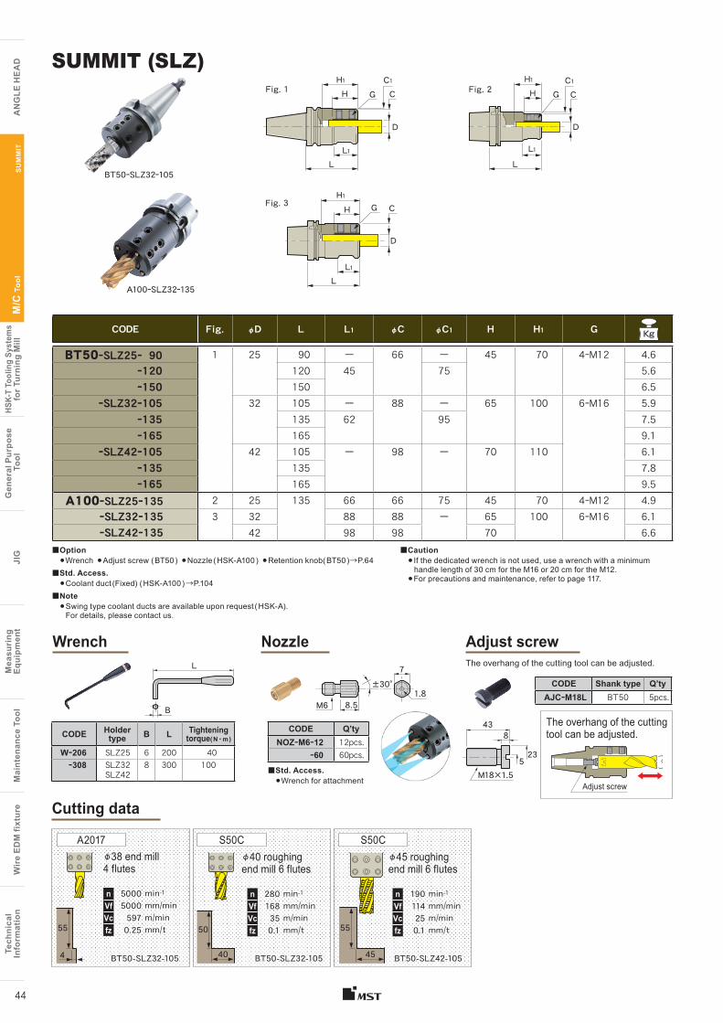
ADSUMMIT
43
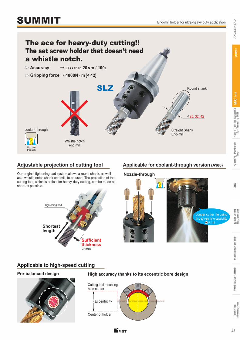
Our original tightening pad system allows a round shank, as well as a whistle notch shank end mill, to be used. The projection of the cutting tool, which is critical for heavy-duty cutting, can be made as short as possible.
Adjustable projection of cutting tool
φ25, 32, 42
SLZ
Sufficient thickness
Tightening pad
Shortest length
coolant-through
Nozzle- through
The ace for heavy-duty cutting!!The set screw holder that doesn’t need a whistle notch.
Applicable for coolant-through version (A100)
Longer cutter life using through-spindle capability
Nozzle-through
P. 117
Pre-balanced design High accuracy thanks to its eccentric bore design
Cutting tool mounting hole center
Center of holder
Eccentricity
Applicable to high-speed cutting
SU
MM
IT
End-mill holder for ultra-heavy duty application
Accuracy Gripping force
→ Less than 20μm / 100L
→ 4000N ・ m (φ 42)
28mm
Straight Shank End-mill
Whistle notch end mill
Round shank
Tech
nica
lIn
form
atio
nW
ire
EDM
fixt
ure
Mai
nten
ance
Too
lM
easu
ring
Equi
pmen
tJI
GG
ener
al P
urpo
se T
ool
HSK-
T To
olin
g Sy
stem
sfo
r Tur
ning
Mill
M/C
Too
l
A
NG
LE H
EA
D
Tech
nica
lIn
form
atio
nW
ire
EDM
fixt
ure
Mai
nten
ance
Too
lM
easu
ring
Eq
uipm
ent
JIG
Gen
eral
Pur
pose
Too
lHS
K-T
Tool
ing
Syst
ems
for T
urni
ng M
illM
/C T
ool
AN
GLE
HE
ADSUMMIT (SLZ)
A100ーSLZ32ー135
Fig. 1
Fig. 3H1
G C
C1
L1
H1H
H
G
L1
L
L
D
D
C Fig. 2
BT50ーSLZ32ー105
H1H
D
L
G
L1
CC1
44
BT50-SLZ32-105
min-1mm/minm/minmm/t
500050005970.25
φ38 end mill 4 flutes
A2017
BT50-SLZ32-105
min-1mm/minm/minmm/t
280168350.1
φ40 roughing end mill 6 flutes
S50C
BT50-SLZ42-105
min-1mm/minm/minmm/t
190114250.1
φ45 roughing end mill 6 flutes
S50C
Cutting data
SU
MM
IT
■Option●Wrench ●Adjust screw ( BT50 ) ●Nozzle ( HSK-A100 ) ●Retention knob( BT50 )→P.64
■Std. Access.●Coolant duct (Fixed) ( HSK-A100 ) →P.104
■Note● Swing type coolant ducts are available upon request ( HSK-A).
For details, please contact us.
■Caution● If the dedicated wrench is not used, use a wrench with a minimum handle length of 30 cm for the M16 or 20 cm for the M12.●For precautions and maintenance, refer to page 117.
55
4
50
40
55
45
nVfVcfz
nVfVcfz
nVfVcfz
Wrench Nozzle Adjust screw
The overhang of the cutting tool can be adjusted.
43
7
1.8M6B
L
8.5
±30°
523
8
M18×1.5Adjust screw
CODE Fig. φD L L1 φC φC1 H H1 G Kg
BT50ーSLZ25ー 90 1 25 90 ー 66 ー 45 70 4ーM12 4.6ー120 120 45 75 5.6ー150 150 6.5
ーSLZ32ー105 32 105 ー 88 ー 65 100 6ーM16 5.9ー135 135 62 95 7.5ー165 165 9.1
ーSLZ42ー105 42 105 ー 98 ー 70 110 6.1ー135 135 7.8ー165 165 9.5
A100ーSLZ25ー135 2 25 135 66 66 75 45 70 4ーM12 4.9ーSLZ32ー135 3 32 88 88 ー 65 100 6ーM16 6.1ーSLZ42ー135 42 98 98 70 6.6
CODE Shank type Q’tyAJCーM18L BT50 5pcs.
CODE Holder type B L Tightening
torque( N ・ m )
Wー206 SLZ25 6 200 40ー308 SLZ32
SLZ428 300 100
CODE Q’tyNOZーM6ー12 12pcs.
ー60 60pcs.
The overhang of the cutting tool can be adjusted.
■Std. Access.●Wrench for attachment
Tech
nica
lIn
form
atio
nW
ire
EDM
fixt
ure
Mai
nten
ance
Too
lM
easu
ring
Equi
pmen
tJI
GG
ener
al P
urpo
se T
ool
HSK-
T To
olin
g Sy
stem
sfo
r Tur
ning
Mill
M/C
Too
l
A
NG
LE H
EA
D
Tech
nica
lIn
form
atio
nW
ire
EDM
fixt
ure
Mai
nten
ance
Too
lM
easu
ring
Eq
uipm
ent
JIG
Gen
eral
Pur
pose
Too
lHS
K-T
Tool
ing
Syst
ems
for T
urni
ng M
illM
/C T
ool
AN
GLE
HE
AD
45
RED SCREW ARBOR
With a solid carbide core
For screw-in end-mills
Ideal for heavy duty roughing application at shallow and deep machining using a face milling arbor with a large size solid carbide core.
Superior Accessibility. Slim tip design of Curve minimizes cutter projection.
MAX. 340
MAX.400
Less vibration at a corner and pocket machining thanks to a solid design using a carbide shaft.
RSG
FMH
1
2
3
Long
φ40〜100 ( FMH standard )
φ16〜40 ( Screw-in cutter )
φ4〜20 ( Carbide cutter )
Carbide
Slim
MAX.400
Superior finishing
surface.
No chattering
Heavy duty rough-
ing application
Thick
RoughingSem
i-finishingFinishing
Large size solid carbide
160
400
MAX. 295
If you would like more detailed information, please contact MST and ask for a SLIMLINE catalog.
Short
Curve
FMH RIGID type
Long
The overhang of the cutting tool can be adjusted.
The solution for high-efficient machining of deep cavity application.
P. 46
P. 48
Tech
nica
lIn
form
atio
nW
ire
EDM
fixt
ure
Mai
nten
ance
Too
lM
easu
ring
Equi
pmen
tJI
GG
ener
al P
urpo
se T
ool
HSK-
T To
olin
g Sy
stem
sfo
r Tur
ning
Mill
M/C
Too
l
A
NG
LE H
EA
D
Tech
nica
lIn
form
atio
nW
ire
EDM
fixt
ure
Mai
nten
ance
Too
lM
easu
ring
Eq
uipm
ent
JIG
Gen
eral
Pur
pose
Too
lHS
K-T
Tool
ing
Syst
ems
for T
urni
ng M
illM
/C T
ool
AN
GLE
HE
AD
46
Available for FMH standard cutting tools that supplies coolant to the cutting edge properly.
Achieves higher efficiency during long gauge length machining.Achieves stable machining during long, continuous operation.
FMH standard
Machining efficiency 2 times (Compared to conventional holders)
FMH-H
L / D = 3
~ 6
Thick body shrinks strongly around the carbide core
φ40~100(FMH standard)
Under-cut design makes it ideal for vertical wall cutting
Cutting depth ap (mm) 0.5 1.0 1.5 2.0
FMH typeBT50-FMH22-60-315H
ConventionalBT50-FMH22-60-300
310 mmap
44
×Chattering
Effective length
coolant-through
The large-diameter carbide core is integrated into the thick body by shrink-fitting. Achieves less deflection and higher efficiency during long-gauge machining. Vibration-free machining leads to longer insert life and achieves stable machining during long and continuous operation.
Effective length of our line up is from 110mm to 360mm and cutter dia of our line up is from φ40 to φ100. Shorter and longer gauge length models added to our current line up. Ideal for deep cavity mold applications. Makes more efficient roughing possible.
Large dia. Carbide core
Even greater efficiency!Thickness
Carbide core
60
360
φ40〜100
with a solid carbide core
● Application Shouldering● Material S50C (Mild steel)● Cutting speed 220 m/min ( S1,112 min -1)● Feed rate 1,112 mm/min
Cutter dia. φ634-flutesRound insert
RIGID
FMH RIGID type
FMH
RIG
ID t
ype
Larg
e dia.
Car
bide c
ore
OSG KYOCERA DIJET INDUSTRIAL Tungaloy MITSUBISHI MATERIALS Mitsubishi Hitachi Tool Engineering
Works with these manufacturers’ cutting tools
NEW
RIGID
Double the Machining efficiency
Comparison test
Tech
nica
lIn
form
atio
nW
ire
EDM
fixt
ure
Mai
nten
ance
Too
lM
easu
ring
Equi
pmen
tJI
GG
ener
al P
urpo
se T
ool
HSK-
T To
olin
g Sy
stem
sfo
r Tur
ning
Mill
M/C
Too
l
A
NG
LE H
EA
D
Tech
nica
lIn
form
atio
nW
ire
EDM
fixt
ure
Mai
nten
ance
Too
lM
easu
ring
Eq
uipm
ent
JIG
Gen
eral
Pur
pose
Too
lHS
K-T
Tool
ing
Syst
ems
for T
urni
ng M
illM
/C T
ool
AN
GLE
HE
AD
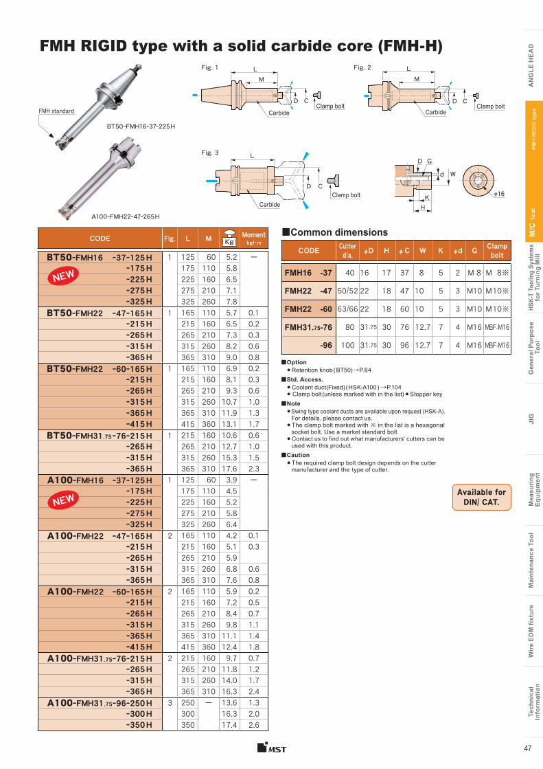
47
FMH RIGID type with a solid carbide core (FMH-H)
CODE Fig. L M Moment kgf • m
BT50ーFMH16 ー37ー125H 1 125 60 5.2 ーー175H 175 110 5.8ー225H 225 160 6.5ー275H 275 210 7.1ー325H 325 260 7.8
BT50ーFMH22 ー47ー165H 1 165 110 5.7 0.1 ー215H 215 160 6.5 0.2 ー265H 265 210 7.3 0.3 ー315H 315 260 8.2 0.6 ー365H 365 310 9.0 0.8
BT50ーFMH22 ー60ー165H 1 165 110 6.9 0.2 ー215H 215 160 8.1 0.3 ー265H 265 210 9.3 0.6 ー315H 315 260 10.7 1.0 ー365H 365 310 11.9 1.3 ー415H 415 360 13.1 1.7
BT50ーFMH31.75 ー76ー215H 1 215 160 10.6 0.6 ー265H 265 210 12.7 1.0 ー315H 315 260 15.3 1.5 ー365H 365 310 17.6 2.3
A100ーFMH16 ー37ー125H 1 125 60 3.9 ーー175H 175 110 4.5ー225H 225 160 5.2ー275H 275 210 5.8ー325H 325 260 6.4
A100ーFMH22 ー47ー165H 2 165 110 4.2 0.1ー215H 215 160 5.1 0.3 ー265H 265 210 5.9 ー315H 315 260 6.8 0.6 ー365H 365 310 7.6 0.8
A100ーFMH22 ー60ー165H 2 165 110 5.9 0.2 ー215H 215 160 7.2 0.5 ー265H 265 210 8.4 0.7 ー315H 315 260 9.8 1.1 ー365H 365 310 11.1 1.4 ー415H 415 360 12.4 1.8
A100ーFMH31.75ー76ー215H 2 215 160 9.7 0.7 ー265H 265 210 11.8 1.2 ー315H 315 260 14.0 1.7 ー365H 365 310 16.3 2.4
A100ーFMH31.75ー96ー250H 3 250 ー 13.6 1.3 ー300H 300 16.3 2.0 ー350H 350 17.4 2.6
■Option● Retention knob ( BT50) →P.64
■Std. Access.● Coolant duct(Fixed) ( HSK-A100 ) →P.104● Clamp bolt (unless marked with in the list) ● Stopper key
■Note● Swing type coolant ducts are available upon request (HSK-A).
For details, please contact us.● The clamp bolt marked with ※ in the list is a hexagonal socket bolt. Use a market standard bolt.● Contact us to find out what manufacturers' cutters can be used with this product.
■Caution● The required clamp bolt design depends on the cutter manufacturer and the type of cutter.
Available for DIN/ CAT.
FMH
RIG
ID t
ype
CODE Cutter dia. φD H φC W K φd G Clamp
bolt
FMH16 -37 40 16 17 37 8 5 2 M 8 M 8※
FMH22 -47 50/52 22 18 47 10 5 3 M10 M10※
FMH22 -60 63/66 22 18 60 10 5 3 M10 M10※
FMH31.75-76 80 31.75 30 76 12.7 7 4 M16 MBF-M16
-96 100 31.75 30 96 12.7 7 4 M16 MBF-M16
■Common dimensionsA100ーFMH22ー47ー265H
FMH standard
D G
Wd
KH
φ16
Fig. 2
C
LM
DCarbide
Clamp bolt
Fig. 3
C
L
D
CarbideClamp bolt
LM
CarbideClamp bolt
Fig. 1
CD
Works with these manufacturers’ cutting tools
BT50ーFMH16ー37ー225H
NEW
NEW
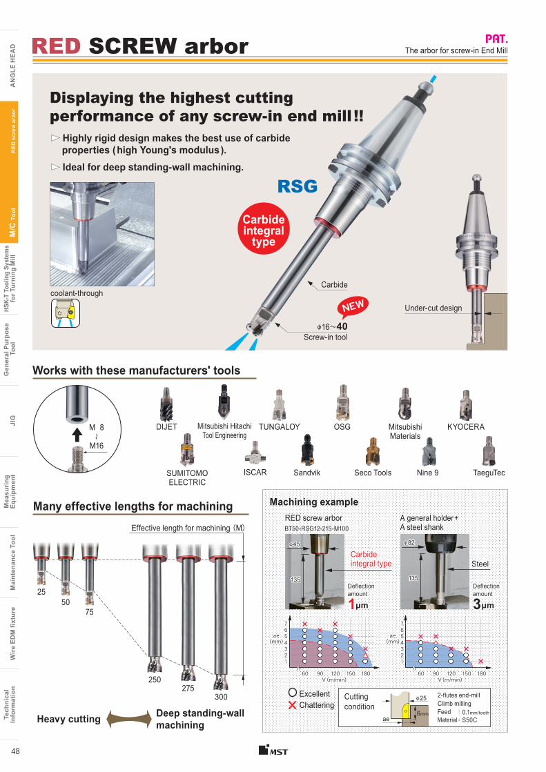
coolant-through
Tech
nica
lIn
form
atio
nW
ire
EDM
fixt
ure
Mai
nten
ance
Too
lM
easu
ring
Equi
pmen
tJI
GG
ener
al P
urpo
se T
ool
HSK-
T To
olin
g Sy
stem
sfo
r Tur
ning
Mill
M/C
Too
l
A
NG
LE H
EA
D
Tech
nica
lIn
form
atio
nW
ire
EDM
fixt
ure
Mai
nten
ance
Too
lM
easu
ring
Eq
uipm
ent
JIG
Gen
eral
Pur
pose
Too
lHS
K-T
Tool
ing
Syst
ems
for T
urni
ng M
illM
/C T
ool
AN
GLE
HE
AD
RE
D s
crew
arb
or
48
Highly rigid design makes the best use of carbide properties ( high Young's modulus ).
Ideal for deep standing-wall machining.
The arbor for screw-in End Mill
Displaying the highest cutting performance of any screw-in end mill !!
RED SCREW arbor
RSG
Many effective lengths for machining Machining example A general holder + A steel shankBT50-RSG12-215-M100
RED screw arbor
Steel135
φ82
3μm
Deflection amount
135
φ45
Carbide integral type
1μm
Deflection amount
Cutting condition
6mm : 0.1mm/toothFeed: S50CMaterialae
2-flutes end-mill Climb milling
φ25 ExcellentChattering
Carbide integral
type
Carbide
Screw-in tool
M 8 〜
M16
Under-cut design
Deep standing-wall machiningHeavy cutting
OSG KYOCERADIJET
Seco Tools
Mitsubishi Materials
SUMITOMO ELECTRIC
Mitsubishi Hitachi Tool Engineering
SandvikISCAR
TUNGALOY
TaeguTec
Effective length for machining (M)
7654321
60 90 120 150 180V (m/min)
ae(mm)
7654321
60 90 120 150 180V (m/min)
ae(mm)
NEW
φ16〜40
Nine 9
250275
300
5075
25
Works with these manufacturers' tools
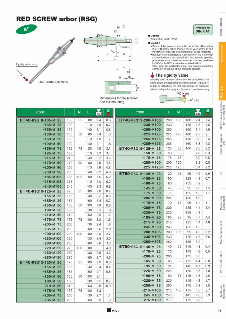
Tech
nica
lIn
form
atio
nW
ire
EDM
fixt
ure
Mai
nten
ance
Too
lM
easu
ring
Equi
pmen
tJI
GG
ener
al P
urpo
se T
ool
HSK-
T To
olin
g Sy
stem
sfo
r Tur
ning
Mill
M/C
Too
l
A
NG
LE H
EA
D
Tech
nica
lIn
form
atio
nW
ire
EDM
fixt
ure
Mai
nten
ance
Too
lM
easu
ring
Eq
uipm
ent
JIG
Gen
eral
Pur
pose
Too
lHS
K-T
Tool
ing
Syst
ems
for T
urni
ng M
illM
/C T
ool
AN
GLE
HE
AD
RE
D s
crew
arb
or
49
BT50ーRSG16ー400ーM225
RED SCREW arbor (RSG)
■Option●Retention knob→ P.64
■Caution● Some of the screw-in end mills cannot be attached to
the RED screw arbor. Please check your screw-in end mills for conformance to the dimensions, or please contact MST.
● Because cutting resistance is greater than the tool holder connection force associated with the machine spindle, please reduce the recommended cutting conditions by 50% for the RED screw arbors marked with ※. Otherwise, the tool holder shank may experience fretting corrosion or fall out of the machine spindle.
A rigidity value represents the amount of deflection for the entire holder and tool when a bending load of 1 kgf (9.8 N) is applied to the tip of the tool. The smaller the numerical value is, the higher the rigidity and the more accurate the machining.
The rigidity value
1kg (9.8N)
S (μm)Dimensions for the screw-in end mill mounting.
H
D
H110
G
Available for DIN/ CAT.
CODE L M L1 S
BT40ーRSG 8ー105ーM 25 105 25 80 1.4 0.6ー135ーM 25 135 110 1.8 0.7ー165ーM 25 165 140 2.1 0.8ー130ーM 50 130 50 80 1.4 1.5ー160ーM 50 160 110 1.8 1.7ー190ーM 50 190 140 2.1 1.8ー155ーM 75 155 75 80 1.5 3.1ー185ーM 75 185 110 1.9 3.4ー215ーM 75 215 140 2.2 3.5ー170ーM 90 170 90 80 1.5 4.5ー200ーM 90 200 110 1.9 4.8ー230ーM 90 230 140 2.2 4.9ー185ーM105 185 105 80 1.6 6.2ー215ーM105 215 110 2.0 6.7ー245ーM105 245 140 2.3 6.8
BT40ーRSG10ー125ーM 25 125 25 100 1.8 0.4ー155ーM 25 155 130 2.2 0.5ー185ーM 25 185 160 2.4 0.7ー150ーM 50 150 50 100 1.9 0.8ー180ーM 50 180 130 2.3 1.0ー210ーM 50 210 160 2.5 1.2ー175ーM 75 175 75 100 2.0 1.6ー205ーM 75 205 130 2.4 1.8ー235ーM 75 235 160 2.6 2.0ー200ーM100 200 100 100 2.0 2.7ー230ーM100 230 130 2.4 3.0ー260ーM100 260 160 2.6 3.3ー220ーM120 220 120 100 2.1 4.0ー250ーM120 250 130 2.5 4.3ー280ーM120 280 160 2.7 4.6
BT40ーRSG12ー125ーM 25 125 25 100 2.0 0.3ー155ーM 25 155 130 2.4 0.4ー185ーM 25 185 160 2.7 0.5ー150ーM 50 150 50 100 2.1ー180ーM 50 180 130 2.5 0.7ー210ーM 50 210 160 2.8 0.9ー175ーM 75 175 75 100 2.3ー205ーM 75 205 130 2.7 1.1ー235ーM 75 235 160 3.0 1.3
CODE L M L1 S
BT40ーRSG12ー200ーM100 200 100 100 2.4 1.4ー230ーM100 230 130 2.8 1.6ー260ーM100 260 160 3.1 1.9ー225ーM125 225 125 100 2.6 2.1ー255ーM125 255 130 3.0 2.4ー285ーM125 285 160 3.3 2.8
BT40ーRSG16ー125ーM 25 125 25 100 2.6 0.2ー150ーM 50 150 50 2.8 0.3ー175ーM 75 175 75 3.0 0.5ー200ーM100 200 100 3.2 0.8ー225ーM125※ 225 125 3.4 1.2
BT50ーRSG 8ー120ーM 25 120 25 95 4.0 0.6ー150ーM 25 150 125 4.3 0.7ー180ーM 25 180 155 4.8ー145ーM 50 145 50 95 4.0 1.5ー175ーM 50 175 125 4.3 1.7ー205ーM 50 205 155 4.8ー170ーM 75 170 75 95 4.1 3.1ー200ーM 75 200 125 4.4 3.4ー230ーM 75 230 155 4.9ー185ーM 90 185 90 95 4.1 4.4ー215ーM 90 215 125 4.4 4.8ー245ーM 90 245 155 4.9ー200ーM105 200 105 95 4.2 6.2ー230ーM105 230 125 4.5 6.6ー260ーM105 260 155 5.0
BT50ーRSG10ー140ーM 25 140 25 115 4.3 0.4ー170ーM 25 170 145 4.6 0.5ー200ーM 25 200 175 5.6ー165ーM 50 165 50 115 4.4 0.8ー195ーM 50 195 145 4.7 0.9ー225ーM 50 225 175 5.7 1.0ー190ーM 75 190 75 115 4.5 1.6ー220ーM 75 220 145 4.8 1.7ー250ーM 75 250 175 5.8 1.8ー215ーM100 215 100 115 4.5 2.7ー245ーM100 245 145 4.8 2.9ー275ーM100 275 175 5.8
S
Rigidity value (μm / kgf)
BTC
ML
L15
C2
Carbide
C1
S
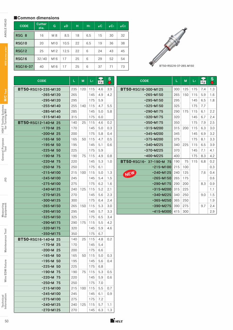
Tech
nica
lIn
form
atio
nW
ire
EDM
fixt
ure
Mai
nten
ance
Too
lM
easu
ring
Equi
pmen
tJI
GG
ener
al P
urpo
se T
ool
HSK-
T To
olin
g Sy
stem
sfo
r Tur
ning
Mill
M/C
Too
l
A
NG
LE H
EA
D
Tech
nica
lIn
form
atio
nW
ire
EDM
fixt
ure
Mai
nten
ance
Too
lM
easu
ring
Eq
uipm
ent
JIG
Gen
eral
Pur
pose
Too
lHS
K-T
Tool
ing
Syst
ems
for T
urni
ng M
illM
/C T
ool
AN
GLE
HE
AD
RE
D s
crew
arb
or
50
CODE L M L1 S
BT50ーRSG10ー235ーM120 235 120 115 4.6 3.9ー265ーM120 265 145 4.9 4.2ー295ーM120 295 175 5.9ー255ーM140 255 140 115 4.7 5.5ー285ーM140 285 145 5.0 5.8ー315ーM140 315 175 6.0
BT50ーRSG12ー140ーM 25 140 25 115 4.6 0.2ー170ーM 25 170 145 5.0 0.3ー200ーM 25 200 175 5.8 0.4ー165ーM 50 165 50 115 4.7 0.5ー195ーM 50 195 145 5.1 0.6ー225ーM 50 225 175 5.9ー190ーM 75 190 75 115 4.9 0.8ー220ーM 75 220 145 5.3 1.0ー250ーM 75 250 175 6.1ー215ーM100 215 100 115 5.0 1.3ー245ーM100 245 145 5.4 1.5ー275ーM100 275 175 6.2 1.6ー240ーM125 240 125 115 5.2 2.1ー270ーM125 270 145 5.6 2.3ー300ーM125 300 175 6.4 2.4ー265ーM150 265 150 115 5.3 3.0ー295ーM150 295 145 5.7 3.3ー325ーM150 325 175 6.5 3.4ー290ーM175 290 175 115 5.5 4.2ー320ーM175 320 145 5.9 4.6ー350ーM175 350 175 6.7
BT50ーRSG16ー140ーM 25 140 25 115 4.8 0.2ー170ーM 25 170 145 5.4ー200ーM 25 200 175 6.6ー165ーM 50 165 50 115 5.0 0.3ー195ーM 50 195 145 5.6 0.4ー225ーM 50 225 175 6.8ー190ーM 75 190 75 115 5.3 0.5ー220ーM 75 220 145 5.9 0.6ー250ーM 75 250 175 7.0ー215ーM100 215 100 115 5.5 0.7ー245ーM100 245 145 6.1 0.9ー275ーM100 275 175 7.2ー240ーM125 240 125 115 5.7 1.1ー270ーM125 270 145 6.3 1.3
CODE L M L1 S
BT50ーRSG16ー300ーM125 300 125 175 7.4 1.3ー265ーM150 265 150 115 5.9 1.6ー295ーM150 295 145 6.5 1.8ー325ーM150 325 175 7.7ー290ーM175 290 175 115 6.1 2.2ー320ーM175 320 145 6.7 2.4ー350ーM175 350 175 7.9 2.5ー315ーM200 315 200 115 6.3 3.0ー345ーM200 345 145 6.9 3.2ー375ーM200 375 175 8.1 3.3ー340ーM225 340 225 115 6.5 3.9ー370ーM225 370 145 7.1 4.1ー400ーM225 400 175 8.3 4.2
BT50ーRSG16ー 37ー190ーM 75 190 75 115 6.8 0.2ー215ーM100 215 100 0.3ー240ーM125 240 125 7.6 0.4ー265ーM150 265 175 0.6ー290ーM175 290 200 8.3 0.9ー315ーM200 315 225 1.1ー340ーM225 340 250 9.0 1.5ー365ーM250 365 250 1.9ー390ーM275 390 275 9.7 2.4ー415ーM300 415 300 2.9
CODE Cutter dia. G φD H H1 φC φC1 φC2
RSG 8 16 M 8 8.5 18 6.5 15 30 32
RSG10 20 M10 10.5 22 6.5 19 36 38
RSG12 25 M12 12.5 22 6 24 43 45
RSG16 32 / 40 M16 17 25 6 29 52 54
RSG16ー37 40 M16 17 25 6 37 71 73
■Common dimensions
NEW
BT50ーRSG16ー37ー265-M150
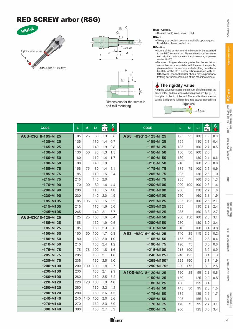
Tech
nica
lIn
form
atio
nW
ire
EDM
fixt
ure
Mai
nten
ance
Too
lM
easu
ring
Equi
pmen
tJI
GG
ener
al P
urpo
se T
ool
HSK-
T To
olin
g Sy
stem
sfo
r Tur
ning
Mill
M/C
Too
l
A
NG
LE H
EA
D
Tech
nica
lIn
form
atio
nW
ire
EDM
fixt
ure
Mai
nten
ance
Too
lM
easu
ring
Eq
uipm
ent
JIG
Gen
eral
Pur
pose
Too
lHS
K-T
Tool
ing
Syst
ems
for T
urni
ng M
illM
/C T
ool
AN
GLE
HE
AD
RE
D s
crew
arb
or
51
A63ーRSG10ー175ーM75
■Std. Access.●Coolant duct(Fixed type) → P.64
■Note● Swing type coolant ducts are available upon request.
For details, please contact us.■Caution
● Some of the screw-in end mills cannot be attached to the RED screw arbor. Please check your screw-in end mills for conformance to the dimensions, or please contact MST.
● Because cutting resistance is greater than the tool holder connection force associated with the machine spindle, please reduce the recommended cutting conditions by 50% for the RED screw arbors marked with ※. Otherwise, the tool holder shank may experience fretting corrosion or fall out of the machine spindle.
Dimensions for the screw-in end mill mounting.
H
D
H110
G
A rigidity value represents the amount of deflection for the entire holder and tool when a bending load of 1 kgf (9.8 N) is applied to the tip of the tool. The smaller the numerical value is, the higher the rigidity and the more accurate the machining.
The rigidity value
1kg (9.8N)
HSK-A
CODE L M L1 S
A63 ーRSG12ー125ーM 25 125 25 100 1.9 0.3ー155ーM 25 155 130 2.3 0.4ー185ーM 25 185 160 2.7 0.5ー150ーM 50 150 50 100 2.0ー180ーM 50 180 130 2.4 0.6ー210ーM 50 210 160 2.8 0.8ー175ーM 75 175 75 100 2.2 0.9ー205ーM 75 205 130 2.6 1.0ー235ーM 75 235 160 3.0 1.3ー200ーM100 200 100 100 2.3 1.4ー230ーM100 230 130 2.7 1.6ー260ーM100 260 160 3.1 1.9ー225ーM125 225 125 100 2.5 2.1ー255ーM125 255 130 2.9 2.4ー285ーM125 285 160 3.3 2.7ー250ーM150 250 150 100 2.6 3.1ー280ーM150 280 130 3.0 3.4ー310ーM150 310 160 3.4 3.8
A63 ーRSG16ー140ーM 25 140 25 115 2.6 0.2ー165ーM 50 165 50 2.8 0.4ー190ーM 75 190 75 3.0 0.6ー215ーM100 215 100 3.2 0.9ー240ーM125※ 240 125 3.4 1.3ー265ーM150※ 265 150 3.7 1.9ー290ーM175※ 290 175 3.9 2.5
A100ーRSG 8ー120ーM 25 120 25 95 2.6 0.6ー150ーM 25 150 125 2.9 0.8ー180ーM 25 180 155 3.4ー145ーM 50 145 50 95 2.6 1.5ー175ーM 50 175 125 2.9 1.7ー205ーM 50 205 155 3.4ー170ーM 75 170 75 95 2.7 3.1ー200ーM 75 200 125 3.0 3.4
CODE L M L1 S
A63ーRSG 8ー105ーM 25 105 25 80 1.3 0.6ー135ーM 25 135 110 1.4 0.7ー165ーM 25 165 140 1.9 0.8ー130ーM 50 130 50 80 1.3 1.5ー160ーM 50 160 110 1.4 1.7ー190ーM 50 190 140 1.9ー155ーM 75 155 75 80 1.4 3.1ー185ーM 75 185 110 1.5 3.4ー215ーM 75 215 140 2.0ー170ーM 90 170 90 80 1.4 4.4ー200ーM 90 200 110 1.5 4.8ー230ーM 90 230 140 2.0 4.9ー185ーM105 185 105 80 1.5 6.2ー215ーM105 215 110 1.6 6.6ー245ーM105 245 140 2.1 6.7
A63ーRSG10ー125ーM 25 125 25 100 1.6 0.4ー155ーM 25 155 130 1.9 0.5ー185ーM 25 185 160 2.3 0.6ー150ーM 50 150 50 100 1.7 0.8ー180ーM 50 180 130 2.0 1.0ー210ーM 50 210 160 2.4 1.2ー175ーM 75 175 75 100 1.8 1.6ー205ーM 75 205 130 2.1 1.8ー235ーM 75 235 160 2.5 2.0ー200ーM100 200 100 100 1.8 2.7ー230ーM100 230 130 2.1 2.9ー260ーM100 260 160 2.5 3.2ー220ーM120 220 120 100 1.9 4.0ー250ーM120 250 130 2.2 4.2ー280ーM120 280 160 2.6 4.5ー240ーM140 240 140 100 2.0 5.6ー270ーM140 270 130 2.3 5.9ー300ーM140 300 160 2.7 6.2
S
Rigidity value (μm / kgf)
S (μm)
S
C
ML
L15
C2C1
Carbide
RED SCREW arbor (RSG)
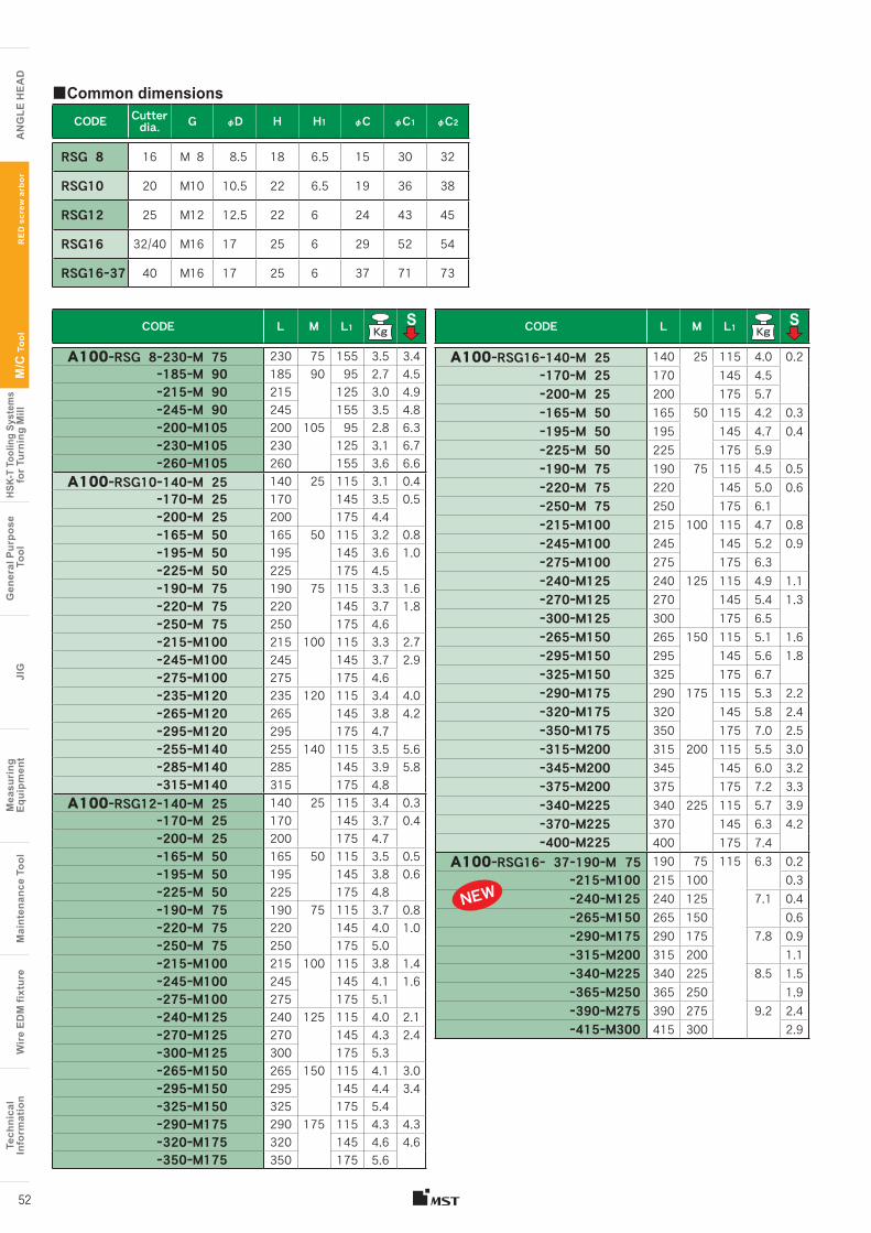
Tech
nica
lIn
form
atio
nW
ire
EDM
fixt
ure
Mai
nten
ance
Too
lM
easu
ring
Equi
pmen
tJI
GG
ener
al P
urpo
se T
ool
HSK-
T To
olin
g Sy
stem
sfo
r Tur
ning
Mill
M/C
Too
l
A
NG
LE H
EA
D
Tech
nica
lIn
form
atio
nW
ire
EDM
fixt
ure
Mai
nten
ance
Too
lM
easu
ring
Eq
uipm
ent
JIG
Gen
eral
Pur
pose
Too
lHS
K-T
Tool
ing
Syst
ems
for T
urni
ng M
illM
/C T
ool
AN
GLE
HE
AD
52
CODE Cutter dia. G φD H H1 φC φC1 φC2
RSG 8 16 M 8 8.5 18 6.5 15 30 32
RSG10 20 M10 10.5 22 6.5 19 36 38
RSG12 25 M12 12.5 22 6 24 43 45
RSG16 32/40 M16 17 25 6 29 52 54
RSG16ー37 40 M16 17 25 6 37 71 73
■Common dimensions
CODE L M L1 S
A100ーRSG 8ー230ーM 75 230 75 155 3.5 3.4ー185ーM 90 185 90 95 2.7 4.5ー215ーM 90 215 125 3.0 4.9ー245ーM 90 245 155 3.5 4.8ー200ーM105 200 105 95 2.8 6.3ー230ーM105 230 125 3.1 6.7ー260ーM105 260 155 3.6 6.6
A100ーRSG10ー140ーM 25 140 25 115 3.1 0.4ー170ーM 25 170 145 3.5 0.5ー200ーM 25 200 175 4.4ー165ーM 50 165 50 115 3.2 0.8ー195ーM 50 195 145 3.6 1.0ー225ーM 50 225 175 4.5ー190ーM 75 190 75 115 3.3 1.6ー220ーM 75 220 145 3.7 1.8ー250ーM 75 250 175 4.6ー215ーM100 215 100 115 3.3 2.7ー245ーM100 245 145 3.7 2.9ー275ーM100 275 175 4.6ー235ーM120 235 120 115 3.4 4.0ー265ーM120 265 145 3.8 4.2ー295ーM120 295 175 4.7ー255ーM140 255 140 115 3.5 5.6ー285ーM140 285 145 3.9 5.8ー315ーM140 315 175 4.8
A100ーRSG12ー140ーM 25 140 25 115 3.4 0.3ー170ーM 25 170 145 3.7 0.4ー200ーM 25 200 175 4.7ー165ーM 50 165 50 115 3.5 0.5ー195ーM 50 195 145 3.8 0.6ー225ーM 50 225 175 4.8ー190ーM 75 190 75 115 3.7 0.8ー220ーM 75 220 145 4.0 1.0ー250ーM 75 250 175 5.0ー215ーM100 215 100 115 3.8 1.4ー245ーM100 245 145 4.1 1.6ー275ーM100 275 175 5.1ー240ーM125 240 125 115 4.0 2.1ー270ーM125 270 145 4.3 2.4ー300ーM125 300 175 5.3ー265ーM150 265 150 115 4.1 3.0ー295ーM150 295 145 4.4 3.4ー325ーM150 325 175 5.4ー290ーM175 290 175 115 4.3 4.3ー320ーM175 320 145 4.6 4.6ー350ーM175 350 175 5.6
CODE L M L1 S
A100ーRSG16ー140ーM 25 140 25 115 4.0 0.2ー170ーM 25 170 145 4.5ー200ーM 25 200 175 5.7ー165ーM 50 165 50 115 4.2 0.3ー195ーM 50 195 145 4.7 0.4ー225ーM 50 225 175 5.9ー190ーM 75 190 75 115 4.5 0.5ー220ーM 75 220 145 5.0 0.6ー250ーM 75 250 175 6.1ー215ーM100 215 100 115 4.7 0.8ー245ーM100 245 145 5.2 0.9ー275ーM100 275 175 6.3ー240ーM125 240 125 115 4.9 1.1ー270ーM125 270 145 5.4 1.3ー300ーM125 300 175 6.5ー265ーM150 265 150 115 5.1 1.6ー295ーM150 295 145 5.6 1.8ー325ーM150 325 175 6.7ー290ーM175 290 175 115 5.3 2.2ー320ーM175 320 145 5.8 2.4ー350ーM175 350 175 7.0 2.5ー315ーM200 315 200 115 5.5 3.0ー345ーM200 345 145 6.0 3.2ー375ーM200 375 175 7.2 3.3ー340ーM225 340 225 115 5.7 3.9ー370ーM225 370 145 6.3 4.2ー400ーM225 400 175 7.4
A100ーRSG16ー 37ー190ーM 75 190 75 115 6.3 0.2ー215ーM100 215 100 0.3ー240ーM125 240 125 7.1 0.4ー265ーM150 265 150 0.6ー290ーM175 290 175 7.8 0.9ー315ーM200 315 200 1.1ー340ーM225 340 225 8.5 1.5ー365ーM250 365 250 1.9ー390ーM275 390 275 9.2 2.4ー415ーM300 415 300 2.9
RE
D s
crew
arb
or
NEW
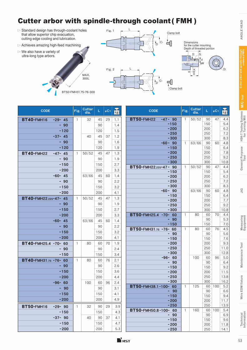
Tech
nica
lIn
form
atio
nW
ire
EDM
fixt
ure
Mai
nten
ance
Too
lM
easu
ring
Equi
pmen
tJI
GG
ener
al P
urpo
se T
ool
HSK-
T To
olin
g Sy
stem
sfo
r Tur
ning
Mill
M/C
Too
l
A
NG
LE H
EA
D
Tech
nica
lIn
form
atio
nW
ire
EDM
fixt
ure
Mai
nten
ance
Too
lM
easu
ring
Eq
uipm
ent
JIG
Gen
eral
Pur
pose
Too
lHS
K-T
Tool
ing
Syst
ems
for T
urni
ng M
illM
/C T
ool
AN
GLE
HE
AD
Standard design has through-coolant holes that allow superior chip evacuation, cutting edge cooling and lubrication.
Achieves amazing high-feed machining
We also have a variety of ultra-long type arbors.
53
W
KH
D1
d D G
D C1
Dimensions for the cutter mountingDepth of threaded portion
Clamp bolt
L
MAX.300L
Cutter arbor with spindle-through coolant ( FMH )
BT50ーFMH31.75ー76ー300
Cut
ter a
rbor
with
spi
ndle
-thr
ough
co
olan
t (FM
H)
CODE Fig. Cutter dia. L φC1 kg
BT40ーFMH16 ー29ー 45 1 32 45 29 1.1ー 90 90 1.4ー 120 120 1.5
ー37ー 45 40 45 37 1.2ー 90 90 1.6ー 120 120 1.9
BT40ーFMH22 ー47ー 45 1 50 / 52 45 47 1.3ー 90 90 1.9ー 150 150 2.7ー 200 200 3.3
ー60ー 45 63 / 66 45 60 1.4ー 90 90 2.2ー 150 150 3.2ー 200 200 4.1
BT40ーFMH22.225ー47ー 45 1 50 / 52 45 47 1.3ー 90 90 1.9ー 150 150 2.7ー 200 200 3.3
ー60ー 45 63 / 66 45 60 1.4ー 90 90 2.2ー 150 150 3.2ー 200 200 4.1
BT40ーFMH25.4 ー70ー 60 1 80 60 70 1.9ー 90 90 2.4ー 150 150 3.4
BT40ーFMH31.75 ー76ー 60 1 80 60 76 2.1ー 90 90 2.6ー 150 150 3.6ー 200 200 4.4
ー96ー 60 100 60 96 2.4ー 90 90 3.1ー 150 150 4.1ー 200 200 4.9
BT50ーFMH16 ー29ー 90 1 32 90 29 3.9ー 150 150 4.3
ー37ー 90 40 90 37 4.1ー 150 150 4.7ー 200 200 5.3
D C1
Clamp boltL Fig. 1
CODE Fig. Cutter dia. L φC1 kg
BT50ーFMH22 ー47 ー 90 1 50 / 52 90 47 4.4 ー 150 150 5.4 ー 200 200 6.2 ー 250 250 7.2 ー 300 300 8.3
ー60 ー 90 1 63 / 66 90 60 4.8 ー 150 150 6.4 ー 200 200 7.8 ー 250 250 9.2 ー 300 300 10.8
BT50ーFMH22.225ー47 ー 90 1 50 / 52 90 47 4.4 ー 150 150 5.4 ー 200 200 6.2 ー 250 250 7.2 ー 300 300 8.3
ー60 ー 90 63 / 66 90 60 4.8 ー 150 150 6.4 ー 200 200 7.7 ー 250 250 9.2 ー 300 300 10.8
BT50ーFMH25.4 ー70ー 60 1 80 60 70 4.4ー 90 90 5.3ー 150 150 7.0
BT50ーFMH31.75 ー76ー 60 1 80 60 76 4.5ー 90 90 5.6ー 150 150 7.6ー 200 200 9.3ー 250 250 11.0ー 300 300 12.8
ー96ー 60 100 60 96 5.0ー 90 90 6.4ー 150 150 9.2ー 200 200 11.5ー 250 250 13.8ー 300 300 16.2
BT50ーFMH38.1ー100ー 60 1 125 60 100 5.2ー 90 90 6.6ー 150 150 9.4ー 200 200 11.7ー 250 250 13.9
BT50ーFMH50.8 ー100ー 60 1 160 60 100 5.4ー 90 90 6.9ー 150 150 9.6ー 200 200 11.8ー 250 250 14.1
Fig. 2
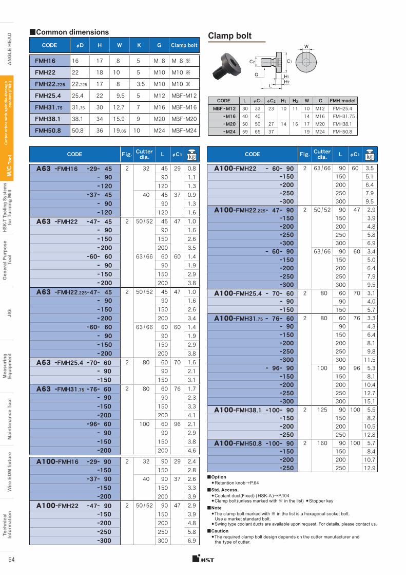
Tech
nica
lIn
form
atio
nW
ire
EDM
fixt
ure
Mai
nten
ance
Too
lM
easu
ring
Equi
pmen
tJI
GG
ener
al P
urpo
se T
ool
HSK-
T To
olin
g Sy
stem
sfo
r Tur
ning
Mill
M/C
Too
l
A
NG
LE H
EA
D
Tech
nica
lIn
form
atio
nW
ire
EDM
fixt
ure
Mai
nten
ance
Too
lM
easu
ring
Eq
uipm
ent
JIG
Gen
eral
Pur
pose
Too
lHS
K-T
Tool
ing
Syst
ems
for T
urni
ng M
illM
/C T
ool
AN
GLE
HE
AD
54
CODE L φC1 φC2 H1 H2 W G FMH modelMBF ー M12 30 33 23 10 11 10 M12 FMH25.4
ー M16 40 40 14 M16 FMH31.75ー M20 50 50 27 14 16 17 M20 FMH38.1ー M24 59 65 37 19 M24 FMH50.8
CODE φD H W K G Clamp bolt
FMH16 16 17 8 5 M 8 M 8 ※
FMH22 22 18 10 5 M10 M10 ※
FMH22.225 22.225 17 8 3.5 M10 M10 ※
FMH25.4 25.4 22 9.5 5 M12 MBFーM12
FMH31.75 31.75 30 12.7 7 M16 MBFーM16
FMH38.1 38.1 34 15.9 9 M20 MBFーM20
FMH50.8 50.8 36 19.05 10 M24 MBFーM24
■Common dimensions
CODE Fig. Cutter dia. L φC1 kg
A63 ーFMH16 ー29ー 45 2 32 45 29 0.8ー 90 90 1.1ー 120 120 1.3
ー37ー 45 40 45 37 0.9ー 90 90 1.3ー 120 120 1.6
A63 ーFMH22 ー47ー 45 2 50 / 52 45 47 1.0ー 90 90 1.6ー 150 150 2.6ー 200 200 3.5
ー60ー 60 63 / 66 60 60 1.4ー 90 90 1.9ー 150 150 2.9ー 200 200 3.8
A63 ーFMH22.225ー47ー 45 2 50 / 52 45 47 1.0ー 90 90 1.6ー 150 150 2.6ー 200 200 3.4
ー60ー 60 63 / 66 60 60 1.4ー 90 90 1.9ー 150 150 2.9ー 200 200 3.8
A63 ーFMH25.4 ー70ー 60 2 80 60 70 1.6ー 90 90 2.1ー150 150 3.1
A63 ーFMH31.75 ー76ー 60 2 80 60 76 1.7ー 90 90 2.3ー150 150 3.3ー200 200 4.1
ー96ー 60 100 60 96 2.1ー 90 90 2.9ー150 150 3.8ー200 200 4.6
A100ーFMH16 ー29ー 90 2 32 90 29 2.4ー150 150 2.8
ー37ー 90 40 90 37 2.6ー150 150 3.3ー200 200 3.9
A100ーFMH22 ー47ー 90 2 50 / 52 90 47 2.9ー150 150 3.9ー200 200 4.8ー250 250 5.8ー300 300 6.9
Clamp bolt
C1 C2
G H1H2
L
W
■Option●Retention knob→P.64
■Std. Access.●Coolant duct(Fixed) ( HSK-A )→P.104 ●Clamp bolt (unless marked with ※ in the list) ●Stopper key
■Note●The clamp bolt marked with ※ in the list is a hexagonal socket bolt. Use a market standard bolt.●Swing type coolant ducts are available upon request. For details, please contact us.
■Caution●The required clamp bolt design depends on the cutter manufacturer and the type of cutter.
Cut
ter a
rbor
with
spi
ndle
-thr
ough
co
olan
t (FM
H)
CODE Fig. Cutter dia. L φC1 kg
A100ーFMH22 ー 60ー 90 2 63 / 66 90 60 3.5ー150 150 5.1ー200 200 6.4ー250 250 7.9ー300 300 9.5
A100ーFMH22.225ー 47ー 90 2 50 / 52 90 47 2.9ー150 150 3.9ー200 200 4.8ー250 250 5.8ー300 300 6.9
ー 60ー 90 63 / 66 90 60 3.4ー150 150 5.0ー200 200 6.4ー250 250 7.9ー300 300 9.5
A100ーFMH25.4 ー 70ー 60 2 80 60 70 3.1ー 90 90 4.0ー150 150 5.7
A100ーFMH31.75 ー 76ー 60 2 80 60 76 3.3ー 90 90 4.3ー150 150 6.4ー200 200 8.1ー250 250 9.8ー300 300 11.5
ー 96ー 90 100 90 96 5.3ー150 150 8.1ー200 200 10.4ー250 250 12.7ー300 300 15.1
A100ーFMH38.1 ー100ー 90 2 125 90 100 5.5ー150 150 8.2ー200 200 10.5ー250 250 12.8
A100ーFMH50.8 ー100ー 90 2 160 90 100 5.7ー150 150 8.4ー200 200 10.7ー250 250 12.9
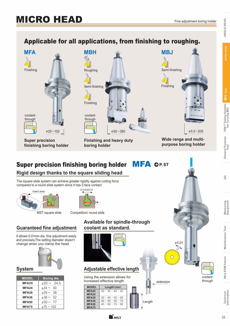
Tech
nica
lIn
form
atio
nW
ire
EDM
fixt
ure
Mai
nten
ance
Too
lM
easu
ring
Equi
pmen
tJI
GG
ener
al P
urpo
se T
ool
HSK-
T To
olin
g Sy
stem
sfo
r Tur
ning
Mill
M/C
Too
l
A
NG
LE H
EA
D
Tech
nica
lIn
form
atio
nW
ire
EDM
fixt
ure
Mai
nten
ance
Too
lM
easu
ring
Eq
uipm
ent
JIG
Gen
eral
Pur
pose
Too
lHS
K-T
Tool
ing
Syst
ems
for T
urni
ng M
illM
/C T
ool
AN
GLE
HE
AD
55
P. 57
MST square slide
Rigid design thanks to the square sliding head
Applicable for all applications, from finishing to roughing.
Available for spindle-through coolant as standard.
MODEL Boring dia.MFA20 φ20 〜 24.5MFA24 φ24 〜 30MFA29 φ29 〜 38MFA36 φ36 〜 52MFA50 φ50 〜 77MFA75 φ75 〜 102
MODEL Length(mm)MFA20 30 ・ 35 ・ 40 ・ 45MFA24MFA29 30 ・ 40 ・ 50 ・ 60MFA36 40 ・ 50 ・ 60 ・ 70MFA50 45 ・ 60 ・ 75 ・ 90MFA75
φ0.01
Competitors' round slide
U nstab l eInsert area
The square slide system can achieve greater rigidity against cutting force compared to a round slide system since it has 2-face contact.
Using the extension allows for increased effective length
Adjustable effective length
Super precision finishing boring holder MFA
Length
extension
Guaranteed fine adjustmentIt allows 0.01mm dia. fine adjustment easily and precisely.The setting diameter doesn't change when you clamp the head.
Fine adjustment boring holder
MFA MBH MBJ
Roughing
Semi-finishing
Finishing
Semi-finishing
Finishing
φ20〜102 φ50〜380 φ5.5〜205
Super precision finishing boring holder
Wide range and multi-purpose boring holder
Finishing and heavy duty boring holder
coolant-through
coolant-through
coolant-through
MICRO HEAD
Finishing
MIC
RO
HE
AD
System
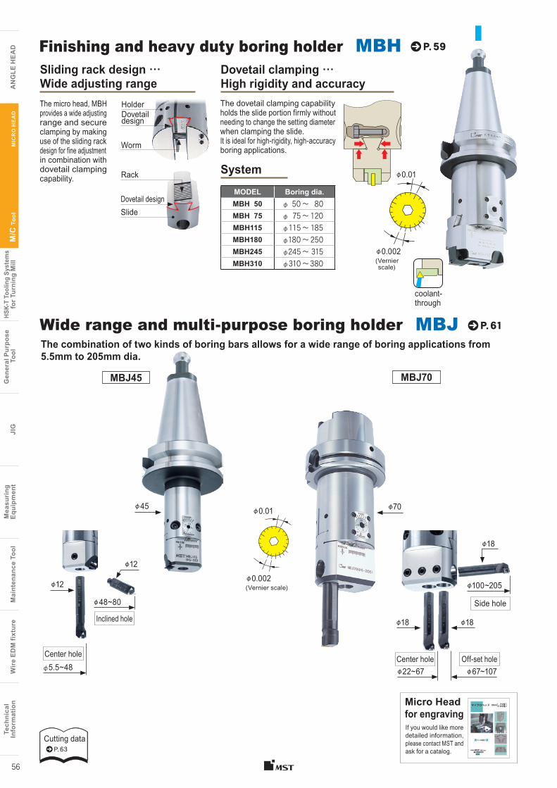
Cutting dataP. 63
Tech
nica
lIn
form
atio
nW
ire
EDM
fixt
ure
Mai
nten
ance
Too
lM
easu
ring
Equi
pmen
tJI
GG
ener
al P
urpo
se T
ool
HSK-
T To
olin
g Sy
stem
sfo
r Tur
ning
Mill
M/C
Too
l
A
NG
LE H
EA
D
Tech
nica
lIn
form
atio
nW
ire
EDM
fixt
ure
Mai
nten
ance
Too
lM
easu
ring
Eq
uipm
ent
JIG
Gen
eral
Pur
pose
Too
lHS
K-T
Tool
ing
Syst
ems
for T
urni
ng M
illM
/C T
ool
AN
GLE
HE
AD
MIC
RO
HE
AD
56
P. 59
Sliding rack design … Wide adjusting range
Dovetail design
Worm
Holder
Dovetail design
Rack
Slide
The micro head, MBH provides a wide adjusting range and secure clamping by making use of the sliding rack design for fine adjustment in combination with dovetail clamping capability. φ0.01
φ0.002 (Vernier scale)
Finishing and heavy duty boring holder MBH
φ0.01
φ0.002 (Vernier scale)
P. 61The combination of two kinds of boring bars allows for a wide range of boring applications from 5.5mm to 205mm dia.
Wide range and multi-purpose boring holder MBJ
MBJ70MBJ45
φ18
φ18
φ18
Off-set holeCenter hole
Side hole
φ100~205
φ67~107φ22~67
Dovetail clamping … High rigidity and accuracy The dovetail clamping capability holds the slide portion firmly without needing to change the setting diameter when clamping the slide. It is ideal for high-rigidity, high-accuracy boring applications.
MODEL Boring dia.MBH 50 φ 50 〜 80MBH 75 φ 75 〜 120MBH115 φ 115 〜 185MBH180 φ180 〜 250MBH245 φ245 〜 315MBH310 φ310 〜 380
System
Micro Head for engravingIf you would like more detailed information, please contact MST and ask for a catalog.
φ12
Center hole
φ48~80
φ12
φ5.5~48
Inclined hole
φ70φ45
coolant-through
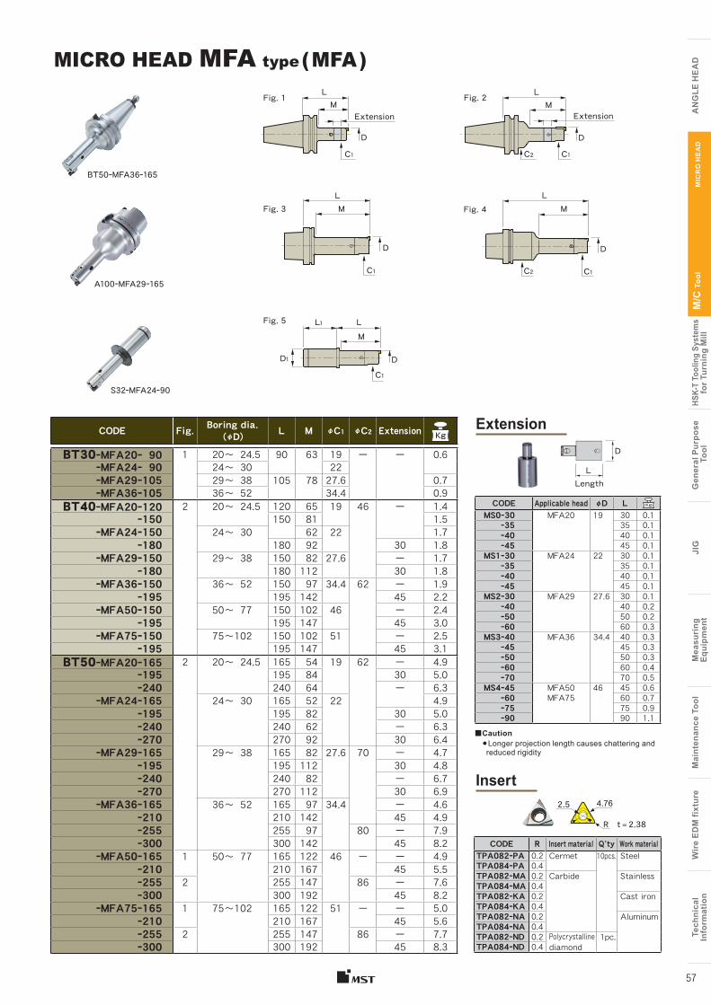
Tech
nica
lIn
form
atio
nW
ire
EDM
fixt
ure
Mai
nten
ance
Too
lM
easu
ring
Equi
pmen
tJI
GG
ener
al P
urpo
se T
ool
HSK-
T To
olin
g Sy
stem
sfo
r Tur
ning
Mill
M/C
Too
l
A
NG
LE H
EA
D
Tech
nica
lIn
form
atio
nW
ire
EDM
fixt
ure
Mai
nten
ance
Too
lM
easu
ring
Eq
uipm
ent
JIG
Gen
eral
Pur
pose
Too
lHS
K-T
Tool
ing
Syst
ems
for T
urni
ng M
illM
/C T
ool
AN
GLE
HE
AD
MIC
RO
HE
AD
57
Extension
Insert
■Caution● Longer projection length causes chattering and reduced rigidity
CODE Fig. Boring dia. (φD) L M φC1 φC2 Extension
BT30ーMFA20ー 90 1 20〜 24.5 90 63 19 ー ー 0.6ーMFA24ー 90 24〜 30 22ーMFA29ー105 29〜 38 105 78 27.6 0.7ーMFA36ー105 36〜 52 34.4 0.9
BT40ーMFA20ー120 2 20〜 24.5 120 65 19 46 ー 1.4ー150 150 81 1.5
ーMFA24ー150 24〜 30 62 22 1.7ー180 180 92 30 1.8
ーMFA29ー150 29〜 38 150 82 27.6 ー 1.7ー180 180 112 30 1.8
ーMFA36ー150 36〜 52 150 97 34.4 62 ー 1.9ー195 195 142 45 2.2
ーMFA50ー150 50〜 77 150 102 46 ー 2.4ー195 195 147 45 3.0
ーMFA75ー150 75〜102 150 102 51 ー 2.5ー195 195 147 45 3.1
BT50ーMFA20ー165 2 20〜 24.5 165 54 19 62 ー 4.9ー195 195 84 30 5.0ー240 240 64 ー 6.3
ーMFA24ー165 24〜 30 165 52 22 4.9ー195 195 82 30 5.0ー240 240 62 ー 6.3ー270 270 92 30 6.4
ーMFA29ー165 29〜 38 165 82 27.6 70 ー 4.7ー195 195 112 30 4.8ー240 240 82 ー 6.7ー270 270 112 30 6.9
ーMFA36ー165 36〜 52 165 97 34.4 ー 4.6ー210 210 142 45 4.9ー255 255 97 80 ー 7.9ー300 300 142 45 8.2
ーMFA50ー165 1 50〜 77 165 122 46 ー ー 4.9ー210 210 167 45 5.5ー255 2 255 147 86 ー 7.6ー300 300 192 45 8.2
ーMFA75ー165 1 75〜102 165 122 51 ー ー 5.0ー210 210 167 45 5.6ー255 2 255 147 86 ー 7.7ー300 300 192 45 8.3
MICRO HEAD MFA type ( MFA )
CODE R Insert material Q’ty Work materialTPA082ーPA 0.2 Cermet 10pcs. SteelTPA084ーPA 0.4TPA082ーMA 0.2 Carbide StainlessTPA084ーMA 0.4TPA082ーKA 0.2 Cast ironTPA084ーKA 0.4TPA082ーNA 0.2 AluminumTPA084ーNA 0.4TPA082ーND 0.2 Polycrystalline
diamond1pc.
TPA084ーND 0.4
CODE Applicable head φD LMS0ー30 MFA20 19 30 0.1 ー35 35 0.1 ー40 40 0.1 ー45 45 0.1MS1ー30 MFA24 22 30 0.1 ー35 35 0.1 ー40 40 0.1 ー45 45 0.1MS2ー30 MFA29 27.6 30 0.1 ー40 40 0.2 ー50 50 0.2 ー60 60 0.3MS3ー40 MFA36 34.4 40 0.3 ー45 45 0.3 ー50 50 0.3 ー60 60 0.4 ー70 70 0.5MS4ー45 MFA50 46 45 0.6 ー60 MFA75 60 0.7 ー75 75 0.9 ー90 90 1.1
2.5
t = 2.38
D
LLength
4.76
R
BT50ーMFA36ー165
L L
Extension Extension
C1 C1C2
D D
M M
A100ーMFA29ー165
S32ーMFA24ー90
Fig. 4L
C1C2
D
M
Fig. 5 LL1
C1
D1 D
M
Fig. 3L
C1
D
M
Fig. 1 Fig. 2
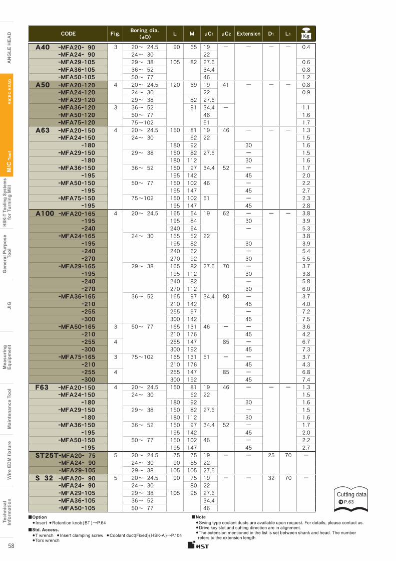
Cutting dataP. 63
Tech
nica
lIn
form
atio
nW
ire
EDM
fixt
ure
Mai
nten
ance
Too
lM
easu
ring
Equi
pmen
tJI
GG
ener
al P
urpo
se T
ool
HSK-
T To
olin
g Sy
stem
sfo
r Tur
ning
Mill
M/C
Too
l
A
NG
LE H
EA
D
Tech
nica
lIn
form
atio
nW
ire
EDM
fixt
ure
Mai
nten
ance
Too
lM
easu
ring
Eq
uipm
ent
JIG
Gen
eral
Pur
pose
Too
lHS
K-T
Tool
ing
Syst
ems
for T
urni
ng M
illM
/C T
ool
AN
GLE
HE
AD
MIC
RO
HE
AD
58
CODE Fig. Boring dia. (φD) L M φC1 φC2 Extension D1 L1 Kg
A40 ーMFA20ー 90 3 20〜 24.5 90 65 19 ー ー ー ー 0.4ーMFA24ー 90 24〜 30 22 ーMFA29ー105 29〜 38 105 82 27.6 0.6ーMFA36ー105 36〜 52 34.4 0.8ーMFA50ー105 50〜 77 46 1.2
A50 ーMFA20ー120 4 20〜 24.5 120 69 19 41 ー ー ー 0.8ーMFA24ー120 24〜 30 22 0.9ーMFA29ー120 29〜 38 82 27.6ーMFA36ー120 3 36〜 52 91 34.4 ー 1.1ーMFA50ー120 50〜 77 46 1.6ーMFA75ー120 75〜102 51 1.7
A63 ーMFA20ー150 4 20〜 24.5 150 81 19 46 ー ー ー 1.3ーMFA24ー150 24〜 30 62 22 1.5
ー180 180 92 30 1.6ーMFA29ー150 29〜 38 150 82 27.6 ー 1.5
ー180 180 112 30 1.6ーMFA36ー150 36〜 52 150 97 34.4 52 ー 1.7
ー195 195 142 45 2.0ーMFA50ー150 50〜 77 150 102 46 ー 2.2
ー195 195 147 45 2.7ーMFA75ー150 75〜102 150 102 51 ー 2.3
ー195 195 147 45 2.8A100 ーMFA20ー165 4 20〜 24.5 165 54 19 62 ー ー ー 3.8
ー195 195 84 30 3.9ー240 240 64 ー 5.3
ーMFA24ー165 24〜 30 165 52 22 3.8ー195 195 82 30 3.9ー240 240 62 ー 5.4ー270 270 92 30 5.5
ーMFA29ー165 29〜 38 165 82 27.6 70 ー 3.7ー195 195 112 30 3.8ー240 240 82 ー 5.8ー270 270 112 30 6.0
ーMFA36ー165 36〜 52 165 97 34.4 80 ー 3.7ー210 210 142 45 4.0ー255 255 97 ー 7.2ー300 300 142 45 7.5
ーMFA50ー165 3 50〜 77 165 131 46 ー ー 3.6ー210 210 176 45 4.2ー255 4 255 147 85 ー 6.7ー300 300 192 45 7.3
ーMFA75ー165 3 75〜102 165 131 51 ー ー 3.7ー210 210 176 45 4.3ー255 4 255 147 85 ー 6.8ー300 300 192 45 7.4
F63 ーMFA20ー150 4 20〜 24.5 150 81 19 46 ー ー ー 1.3ーMFA24ー150 24〜 30 62 22 1.5
ー180 180 92 30 1.6ーMFA29ー150 29〜 38 150 82 27.6 ー 1.5
ー180 180 112 30 1.6ーMFA36ー150 36〜 52 150 97 34.4 52 ー 1.7
ー195 195 142 45 2.0ーMFA50ー150 50〜 77 150 102 46 ー 2.2
ー195 195 147 45 2.7ST25TーMFA20ー 75 5 20〜 24.5 75 75 19 ー ー 25 70 ー
ーMFA24ー 90 24〜 30 90 85 22ーMFA29ー105 29〜 38 105 105 27.6
S 32 ーMFA20ー 90 5 20〜 24.5 90 75 19 ー ー 32 70 ーーMFA24ー 90 24〜 30 80 22ーMFA29ー105 29〜 38 105 95 27.6 ーMFA36ー105 36〜 52 34.4 ーMFA50ー105 50〜 77 46
■Option● Insert ●Retention knob ( BT ) →P.64
■Std. Access.●T wrench ● Insert clamping screw ●Coolant duct(Fixed) ( HSK-A )→P.104●Torx wrench
■Note●Swing type coolant ducts are available upon request. For details, please contact us.●Drive key slot and cutting direction are in alignment. ●The extension mentioned in the list is set between shank and head. The number refers to the extension length.
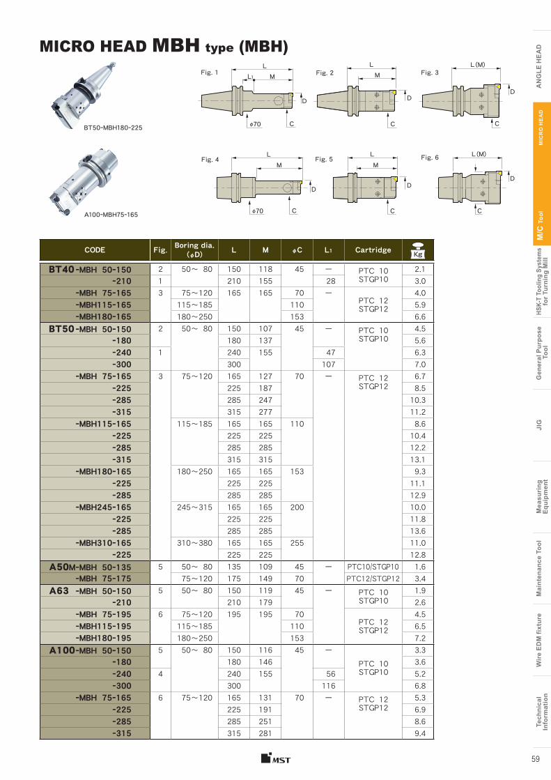
Tech
nica
lIn
form
atio
nW
ire
EDM
fixt
ure
Mai
nten
ance
Too
lM
easu
ring
Equi
pmen
tJI
GG
ener
al P
urpo
se T
ool
HSK-
T To
olin
g Sy
stem
sfo
r Tur
ning
Mill
M/C
Too
l
A
NG
LE H
EA
D
Tech
nica
lIn
form
atio
nW
ire
EDM
fixt
ure
Mai
nten
ance
Too
lM
easu
ring
Eq
uipm
ent
JIG
Gen
eral
Pur
pose
Too
lHS
K-T
Tool
ing
Syst
ems
for T
urni
ng M
illM
/C T
ool
AN
GLE
HE
AD
MIC
RO
HE
AD
59
CODE Fig. Boring dia.(φD) L M φC L1 CartridgeKg
BT40 ーMBH 50ー150 2 50〜 80 150 118 45 ー PTC 10STGP10
2.1 ー210 1 210 155 28 3.0 ーMBH 75ー165 3 75〜120 165 165 70 ー
PTC 12STGP12
4.0 ーMBH115ー165 115〜185 110 5.9 ーMBH180ー165 180〜250 153 6.6
BT50 ーMBH 50ー150 2 50〜 80 150 107 45 ー PTC 10STGP10
4.5 ー180 180 137 5.6 ー240 1 240 155 47 6.3 ー300 300 107 7.0 ーMBH 75ー165 3 75〜120 165 127 70 ー PTC 12
STGP126.7
ー225 225 187 8.5 ー285 285 247 10.3 ー315 315 277 11.2 ーMBH115ー165 115〜185 165 165 110 8.6 ー225 225 225 10.4 ー285 285 285 12.2 ー315 315 315 13.1
ーMBH180ー165 180〜250 165 165 153 9.3 ー225 225 225 11.1 ー285 285 285 12.9 ーMBH245ー165 245〜315 165 165 200 10.0 ー225 225 225 11.8 ー285 285 285 13.6
ーMBH310ー165 310〜380 165 165 255 11.0 ー225 225 225 12.8
A50MーMBH 50ー135 5 50〜 80 135 109 45 ー PTC10/STGP10 1.6ーMBH 75ー175 75〜120 175 149 70 PTC12/STGP12 3.4
A63 ーMBH 50ー150 5 50〜 80 150 119 45 ー PTC 10STGP10
1.9 ー210 210 179 2.6
ーMBH 75ー195 6 75〜120 195 195 70PTC 12STGP12
4.5 ーMBH115ー195 115〜185 110 6.5 ーMBH180ー195 180〜250 153 7.2
A100ーMBH 50ー150 5 50〜 80 150 116 45 ーPTC 10STGP10
3.3 ー180 180 146 3.6 ー240 4 240 155 56 5.2 ー300 300 116 6.8
ーMBH 75ー165 6 75〜120 165 131 70 ー PTC 12STGP12
5.3 ー225 225 191 6.9 ー285 285 251 8.6 ー315 315 281 9.4
MICRO HEAD MBH type (MBH)
BT50ーMBH180ー225
A100ーMBH75ー165
Fig. 6
LM
D
C
Fig. 2LM
D
C
Fig. 3L(M)
D
C
Fig. 4LM
D
Fig. 5LM
D
L(M)
D
CC
φ70
L1Fig. 1
Cφ70
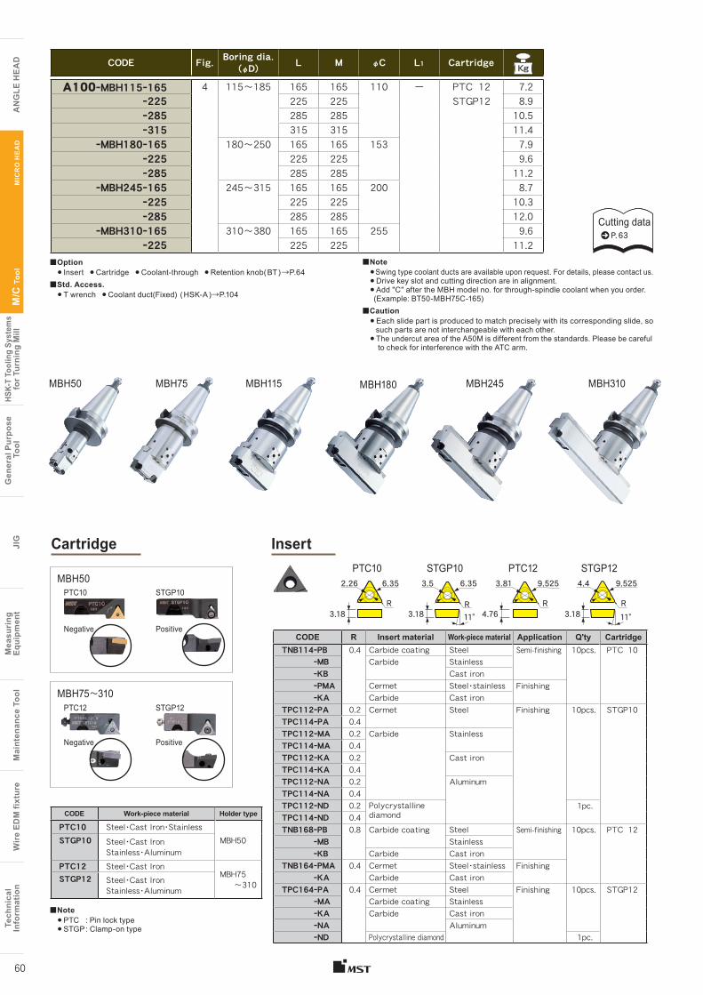
Cutting dataP. 63
MBH50 MBH75 MBH115 MBH180 MBH245 MBH310
Tech
nica
lIn
form
atio
nW
ire
EDM
fixt
ure
Mai
nten
ance
Too
lM
easu
ring
Equi
pmen
tJI
GG
ener
al P
urpo
se T
ool
HSK-
T To
olin
g Sy
stem
sfo
r Tur
ning
Mill
M/C
Too
l
A
NG
LE H
EA
D
Tech
nica
lIn
form
atio
nW
ire
EDM
fixt
ure
Mai
nten
ance
Too
lM
easu
ring
Eq
uipm
ent
JIG
Gen
eral
Pur
pose
Too
lHS
K-T
Tool
ing
Syst
ems
for T
urni
ng M
illM
/C T
ool
AN
GLE
HE
AD
MIC
RO
HE
AD
60
Cartridge
CODE Fig. Boring dia. (φD) L M φC L1 CartridgeKg
A100ーMBH115ー165 4 115〜185 165 165 110 ー PTC 12 7.2 ー225 225 225 STGP12 8.9 ー285 285 285 10.5 ー315 315 315 11.4
ーMBH180ー165 180〜250 165 165 153 7.9 ー225 225 225 9.6 ー285 285 285 11.2
ーMBH245ー165 245〜315 165 165 200 8.7 ー225 225 225 10.3 ー285 285 285 12.0
ーMBH310ー165 310〜380 165 165 255 9.6 ー225 225 225 11.2
CODE Work-piece material Holder type
PTC10 Steel・Cast Iron・StainlessMBH50STGP10 Steel・Cast Iron
Stainless・AluminumPTC12 Steel・Cast Iron
MBH75 〜310STGP12 Steel・Cast Iron
Stainless・Aluminum
■Note● PTC : Pin lock type● STGP : Clamp-on type
PTC10
Negative
Negative
PTC12
STGP10
Positive
Positive
STGP12
MBH50
MBH75〜310
Insert PTC10 PTC12STGP10 STGP12
R
2.26 6.35
3.18 3.18 3.184.7611° 11°
3.5 6.35 3.81 9.525 4.4 9.525
RRR
■Option● Insert ● Cartridge ● Coolant-through ● Retention knob( BT ) →P.64
■Std. Access.● T wrench ● Coolant duct(Fixed) ( HSK-A )→P.104
■Note●Swing type coolant ducts are available upon request. For details, please contact us.● Drive key slot and cutting direction are in alignment.● Add "C" after the MBH model no. for through-spindle coolant when you order. (Example: BT50-MBH75C-165)
■Caution● Each slide part is produced to match precisely with its corresponding slide, so such parts are not interchangeable with each other.● The undercut area of the A50M is different from the standards. Please be careful to check for interference with the ATC arm.
CODE R Insert material Work-piece material Application Q'ty CartridgeTNB114ーPB 0.4 Carbide coating Steel Semi-finishing 10pcs. PTC 10
ーMB Carbide StainlessーKB Cast ironーPMA Cermet Steel・stainless FinishingーKA Carbide Cast iron
TPC112ーPA 0.2 Cermet Steel Finishing 10pcs. STGP10TPC114ーPA 0.4TPC112ーMA 0.2 Carbide StainlessTPC114ーMA 0.4TPC112ーKA 0.2 Cast ironTPC114ーKA 0.4TPC112ーNA 0.2 AluminumTPC114ーNA 0.4TPC112ーND 0.2 Polycrystalline
diamond 1pc.
TPC114ーND 0.4TNB168ーPB 0.8 Carbide coating Steel Semi-finishing 10pcs. PTC 12
ーMB StainlessーKB Carbide Cast iron
TNB164ーPMA 0.4 Cermet Steel・stainless FinishingーKA Carbide Cast iron
TPC164ーPA 0.4 Cermet Steel Finishing 10pcs. STGP12ーMA Carbide coating StainlessーKA Carbide Cast ironーNA AluminumーND Polycrystalline diamond 1pc.
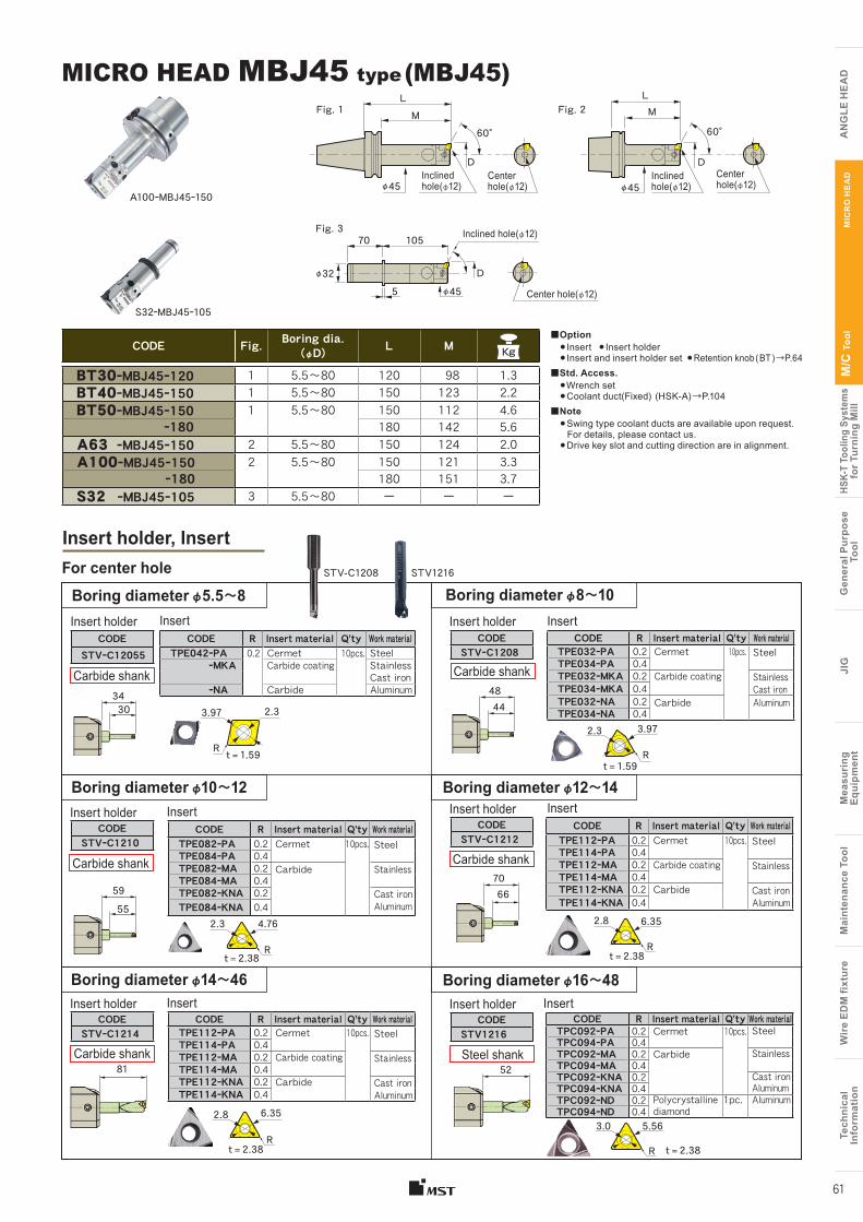
Tech
nica
lIn
form
atio
nW
ire
EDM
fixt
ure
Mai
nten
ance
Too
lM
easu
ring
Equi
pmen
tJI
GG
ener
al P
urpo
se T
ool
HSK-
T To
olin
g Sy
stem
sfo
r Tur
ning
Mill
M/C
Too
l
A
NG
LE H
EA
D
Tech
nica
lIn
form
atio
nW
ire
EDM
fixt
ure
Mai
nten
ance
Too
lM
easu
ring
Eq
uipm
ent
JIG
Gen
eral
Pur
pose
Too
lHS
K-T
Tool
ing
Syst
ems
for T
urni
ng M
illM
/C T
ool
AN
GLE
HE
AD
MIC
RO
HE
AD
61
CODE Fig. Boring dia.(φD) L M Kg
BT30ーMBJ45ー120 1 5.5〜80 120 98 1.3BT40ーMBJ45ー150 1 5.5〜80 150 123 2.2BT50ーMBJ45ー150 1 5.5〜80 150 112 4.6
ー180 180 142 5.6A63 ーMBJ45ー150 2 5.5〜80 150 124 2.0 A100ーMBJ45ー150 2 5.5〜80 150 121 3.3
ー180 180 151 3.7 S32 ーMBJ45ー105 3 5.5〜80 ー ー ー
MICRO HEAD MBJ45 type (MBJ45)
■Option● Insert ● Insert holder ● Insert and insert holder set ●Retention knob ( BT ) →P.64
■Std. Access.●Wrench set●Coolant duct(Fixed) (HSK-A) →P.104
■Note●Swing type coolant ducts are available upon request. For details, please contact us.●Drive key slot and cutting direction are in alignment.
STV-C1208 STV1216
CODE R Insert material Q'ty Work materialTPE042ーPA 0.2 Cermet 10pcs. Steel
ーMKA Carbide coating StainlessCast iron
ーNA Carbide Aluminum
CODESTVーC12055
CODE R Insert material Q'ty Work materialTPE032ーPA 0.2 Cermet 10pcs. SteelTPE034ーPA 0.4TPE032ーMKA 0.2 Carbide coating StainlessTPE034ーMKA 0.4 Cast ironTPE032ーNA 0.2 Carbide AluminumTPE034ーNA 0.4
CODESTVーC1208
CODE R Insert material Q'ty Work materialTPE082ーPA 0.2 Cermet 10pcs. SteelTPE084ーPA 0.4TPE082ーMA 0.2 Carbide StainlessTPE084ーMA 0.4TPE082ーKNA 0.2 Cast ironTPE084ーKNA 0.4 Aluminum
CODESTVーC1210
4844
For center hole
CODE R Insert material Q'ty Work materialTPE112ーPA 0.2 Cermet 10pcs. SteelTPE114ーPA 0.4TPE112ーMA 0.2 Carbide coating StainlessTPE114ーMA 0.4TPE112ーKNA 0.2 Carbide Cast ironTPE114ーKNA 0.4 Aluminum
CODESTVーC1212
CODE R Insert material Q'ty Work materialTPE112ーPA 0.2 Cermet 10pcs. SteelTPE114ーPA 0.4TPE112ーMA 0.2 Carbide coating StainlessTPE114ーMA 0.4TPE112ーKNA 0.2 Carbide Cast ironTPE114ーKNA 0.4 Aluminum
CODESTVーC1214
CODE R Insert material Q'ty Work materialTPC092ーPA 0.2 Cermet 10pcs. SteelTPC094ーPA 0.4TPC092ーMA 0.2 Carbide StainlessTPC094ーMA 0.4TPC092ーKNA 0.2 Cast ironTPC094ーKNA 0.4 AluminumTPC092ーND 0.2 Polycrystalline
diamond1pc. Aluminum
TPC094ーND 0.4
CODESTV1216
5281
7066
Insert holder Insert holder
Insert holder
Insert holder
Insert holder
Insert holder
Insert Insert
InsertInsert
Insert Insert
Boring diameter φ5.5〜8 Boring diameter φ8〜10
Boring diameter φ12〜14
Boring diameter φ16〜48
Boring diameter φ10〜12
Boring diameter φ14〜46
Carbide shank
34
59
30
55
3.97
4.76
2.3
2.3
R
R
R
R
Insert holder, Insert
t = 1.59
t = 2.38
2.8 6.35
t = 2.38
2.3 3.97
t = 1.59
2.8 6.35
t = 2.38
3.0 5.56
t = 2.38
R
R
Steel shank
Carbide shank Carbide shank
Carbide shankCarbide shank
A100ーMBJ45ー150
S32ーMBJ45ー105
Fig. 1 Fig. 2LM
D
60°
Inclined hole(φ12)
Center hole(φ12)φ45
LM
D
60°
Inclined hole(φ12)
Center hole(φ12)φ45
Fig. 3
D
70
5
105 Inclined hole(φ12)
Center hole(φ12)φ45φ32
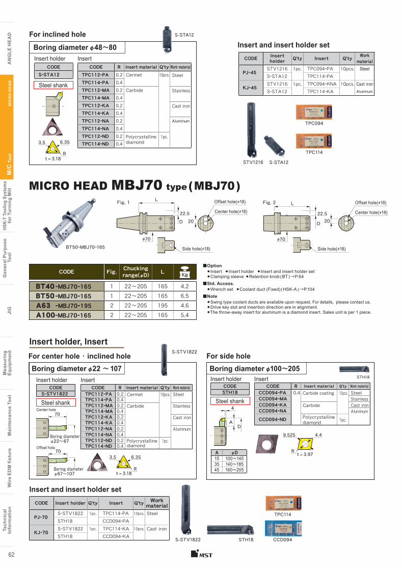
Tech
nica
lIn
form
atio
nW
ire
EDM
fixt
ure
Mai
nten
ance
Too
lM
easu
ring
Equi
pmen
tJI
GG
ener
al P
urpo
se T
ool
HSK-
T To
olin
g Sy
stem
sfo
r Tur
ning
Mill
M/C
Too
l
A
NG
LE H
EA
D
Tech
nica
lIn
form
atio
nW
ire
EDM
fixt
ure
Mai
nten
ance
Too
lM
easu
ring
Eq
uipm
ent
JIG
Gen
eral
Pur
pose
Too
lHS
K-T
Tool
ing
Syst
ems
for T
urni
ng M
illM
/C T
ool
AN
GLE
HE
AD
MIC
RO
HE
AD
62
S-STA12
STV1216 S-STA12
TPC114
CCD094
TPC094
TPC114
Insert and insert holder set
Insert holder, Insert
MICRO HEAD MBJ70 type ( MBJ70 )
For center hole ・ inclined hole For side hole
CODE R Insert material Q'ty Work materialTPC112ーPA 0.2 Cermet 10pcs. SteelTPC114ーPA 0.4TPC112ーMA 0.2 Carbide StainlessTPC114ーMA 0.4TPC112ーKA 0.2 Cast ironTPC114ーKA 0.4TPC112ーNA 0.2 Aluminum
TPC114ーNA 0.4TPC112ーND 0.2 Polycrystalline
diamond1pc.
TPC114ーND 0.4
CODESーSTA12
For inclined hole
Boring diameter φ48〜80
Boring diameter φ22 〜 107 Boring diameter φ100〜205
Insert holder Insert
3.5
t = 3.18
6.35
Insert and insert holder setCODE Insert
holder Q'ty Insert Q'ty Work material
PJー45STV1216 1pc. TPC094ーPA 10pcs. SteelSーSTA12 TPC114ーPA
KJー45STV1216 1pc. TPC094ーKNA 10pcs. Cast ironSーSTA12 TPC114ーKA Aluminum
R
CODESーSTV1822
Insert holder
Center hole
Offset hole
70
70
Boring diameter φ22〜67
Boring diameter φ67〜107
CODE R Insert material Q'ty Work materialCCD094ーPA 0.4 Carbide coating 10pcs. SteelCCD094ーMA StainlessCCD094ーKA Carbide Cast ironCCD094ーNA AluminumCCD094ーND Polycrystalline
diamond 1pc.
Insert
t = 3.97
4.49.525
R
CODE R Insert material Q'ty Work materialTPC112ーPA 0.2 Cermet 10pcs. SteelTPC114ーPA 0.4TPC112ーMA 0.2 Carbide StainlessTPC114ーMA 0.4TPC112ーKA 0.2 Cast ironTPC114ーKA 0.4TPC112ーNA 0.2 AluminumTPC114ーNA 0.4TPC112ーND 0.2 Polycrystalline
diamond1pc.
TPC114ーND 0.4
Insert
3.5 6.35
t = 3.18R
A φD15 100〜14535 140〜18545 160〜205
CODESTH18
Insert holder
DA
4
S-STV1822
S-STV1822 STH18
STH18
CODE Insert holder Q'ty Insert Q'ty Work material
PJー70SーSTV1822 1pc. TPC114ーPA 10pcs. SteelSTH18 CCD094ーPA
KJー70SーSTV1822 1pc. TPC114ーKA 10pcs. Cast ironSTH18 CCD094ーKA
Steel shank
Steel shank Steel shank
CODE Fig. Chucking range(φD) LKg
BT40 ーMBJ70ー165 1 22〜205 165 4.2BT50 ーMBJ70ー165 1 22〜205 165 6.5A63 ーMBJ70ー195 2 22〜205 195 4.6A100ーMBJ70ー165 2 22〜205 165 5.4
■Option● Insert ● Insert holder ● Insert and insert holder set ●Clamping sleeve ●Retention knob ( BT ) →P.64
■Std. Access.●Wrench set ●Coolant duct (Fixed) ( HSK-A ) →P.104
■Note●Swing type coolant ducts are available upon request. For details, please contact us.●Drive key slot and insertion direction are in alignment.●The throw-away insert for aluminum is a diamond insert. Sales unit is per 1 piece.
BT50ーMBJ70ー165
Fig. 1
2022.5D
φ70
Side hole(φ18)
Center hole(φ18)
Offset hole(φ18) Fig. 2 LL
2022.5
D
φ70
Side hole(φ18)
Center hole(φ18)
Offset hole(φ18)
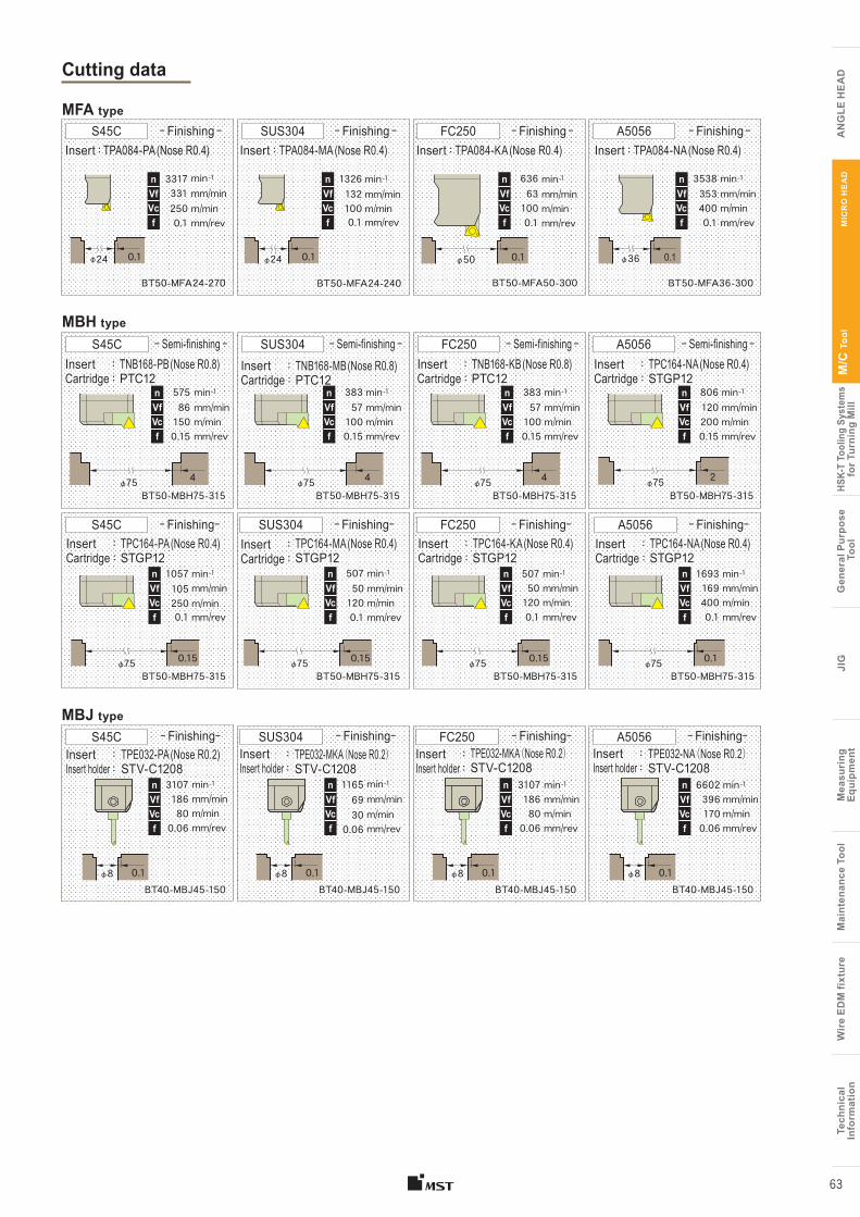
Tech
nica
lIn
form
atio
nW
ire
EDM
fixt
ure
Mai
nten
ance
Too
lM
easu
ring
Equi
pmen
tJI
GG
ener
al P
urpo
se T
ool
HSK-
T To
olin
g Sy
stem
sfo
r Tur
ning
Mill
M/C
Too
l
A
NG
LE H
EA
D
Tech
nica
lIn
form
atio
nW
ire
EDM
fixt
ure
Mai
nten
ance
Too
lM
easu
ring
Eq
uipm
ent
JIG
Gen
eral
Pur
pose
Too
lHS
K-T
Tool
ing
Syst
ems
for T
urni
ng M
illM
/C T
ool
AN
GLE
HE
AD
MIC
RO
HE
AD
63
Cutting data
MBJ type
MFA type
MBH type
BT50-MBH75-315
min-1mm/minm/minmm/rev
575861500.15
nVfVcf
TNB168-PB (Nose R0.8) PTC12
S45C
4φ75
Insert :Cartridge :
ー Semi-finishing ー
4φ75
TNB168-MB (Nose R0.8) PTC12
BT50-MBH75-315
min-1mm/minm/minmm/rev
383571000.15
nVfVcf
SUS304Insert :Cartridge :
ー Semi-finishing ー
4φ75BT50-MBH75-315
min-1mm/minm/minmm/rev
383571000.15
nVfVcf
FC250TNB168-KB (Nose R0.8) PTC12
Insert :Cartridge :
ー Semi-finishing ー
2φ75BT50-MBH75-315
min-1mm/minm/minmm/rev
8061202000.15
nVfVcf
A5056TPC164-NA (Nose R0.4) STGP12
Insert :Cartridge :
ー Semi-finishing ー
BT50-MBH75-315
min-1mm/minm/minmm/rev
10571052500.1
nVfVcf
S45CTPC164-PA (Nose R0.4) STGP12
Insert :Cartridge :
ーFinishingー
0.15φ75BT50-MBH75-315
min-1mm/minm/minmm/rev
507501200.1
nVfVcf
SUS304TPC164-MA (Nose R0.4) STGP12
Insert :Cartridge :
ーFinishingー
0.15φ75BT50-MBH75-315
min-1mm/minm/minmm/rev
507501200.1
nVfVcf
FC250TPC164-KA (Nose R0.4) STGP12
Insert :Cartridge :
ーFinishingー
0.15φ75BT50-MBH75-315
min-1mm/minm/minmm/rev
16931694000.1
nVfVcf
A5056TPC164-NA (Nose R0.4) STGP12
Insert :Cartridge :
ーFinishingー
0.1φ75
BT40-MBJ45-150
min-1mm/minm/minmm/rev
nVfVcf
S45CTPE032-PA (Nose R0.2) STV-C1208
Insert :Insert holder :
ーFinishingー
3107186800.06
φ8 0.1BT40-MBJ45-150
min-1mm/minm/minmm/rev
nVfVcf
SUS304TPE032-MKA (Nose R0.2) STV-C1208
ーFinishingーInsert :Insert holder :
116569300.06
φ8 0.1BT40-MBJ45-150
min-1mm/minm/minmm/rev
nVfVcf
FC250TPE032-MKA (Nose R0.2)STV-C1208
ーFinishingーInsert :Insert holder :
3107186800.06
φ8 0.1BT40-MBJ45-150
nVfVcf
A5056TPE032-NA (Nose R0.2)STV-C1208
ーFinishingーInsert :Insert holder :
66023961700.06
min-1mm/minm/minmm/rev
φ8 0.1
BT50-MFA36-300
min-1mm/minm/minmm/rev
35383534000.1
nVfVcf
TPA084-NA (Nose R0.4)A5056
Insert :ーFinishing ー
φ36 0.1
BT50-MFA24-240
min-1mm/minm/minmm/rev
nVfVcf
TPA084-MA (Nose R0.4)SUS304
Insert :ーFinishing ー
13261321000.1
φ24 0.1
BT50-MFA24-270
min-1mm/minm/minmm/rev
nVfVcf
TPA084-PA (Nose R0.4)ーFinishing ー
Insert :S45C
33173312500.1
φ24 0.1
BT50-MFA50-300
min-1mm/minm/minmm/rev
636631000.1
nVfVcf
FC250TPA084-KA (Nose R0.4)Insert :
ーFinishing ー
φ50 0.1
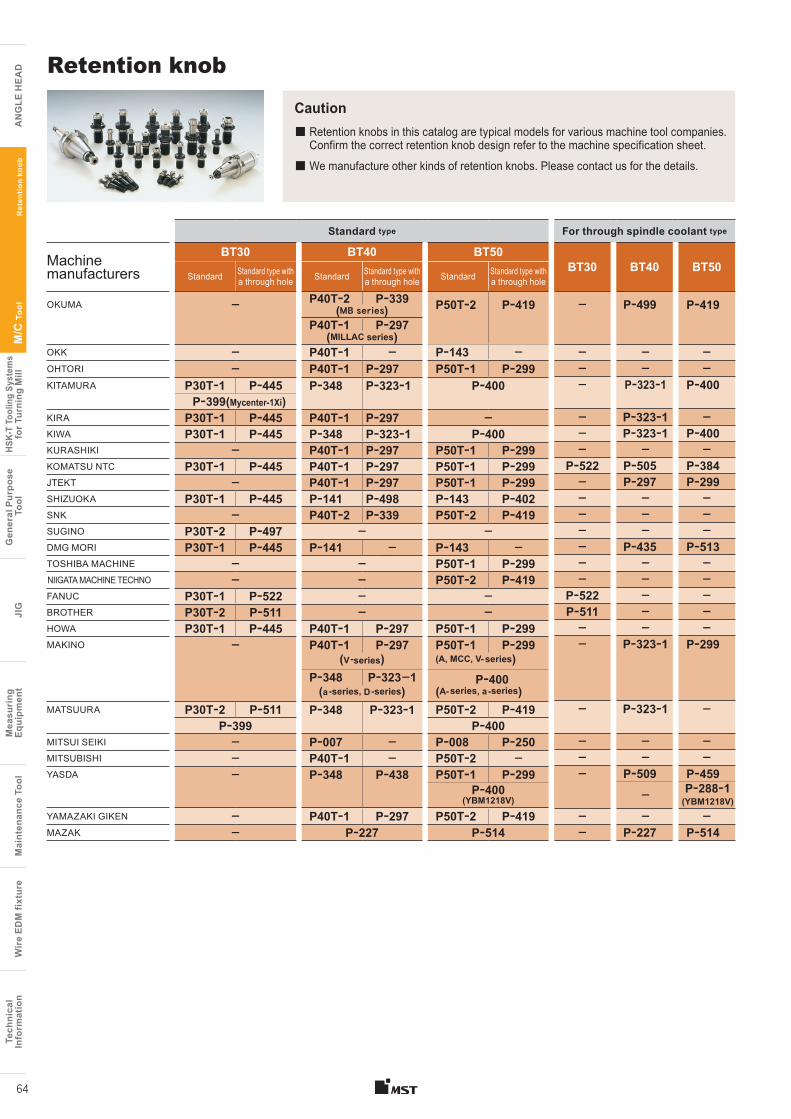
Caution
Retention knob
■ Retention knobs in this catalog are typical models for various machine tool companies. Confirm the correct retention knob design refer to the machine specification sheet.
■ We manufacture other kinds of retention knobs. Please contact us for the details.
Standard type
Machine manufacturers
BT30 BT40 BT50
Standard Standard type with a through hole Standard Standard type with
a through hole Standard Standard type with a through hole
OKUMA ー P40Tー2 Pー339 P50Tー2 Pー419(MB series)P40Tー1 Pー297
(MILLAC series)OKK ー P40Tー1 ー Pー143 ーOHTORI ー P40Tー1 Pー297 P50Tー1 Pー299KITAMURA P30Tー1 Pー445 Pー348 Pー323ー1 Pー400
Pー399(Mycenter-1Xi)KIRA P30Tー1 Pー445 P40Tー1 Pー297 ーKIWA P30Tー1 Pー445 Pー348 Pー323ー1 Pー400KURASHIKI ー P40Tー1 Pー297 P50Tー1 Pー299KOMATSU NTC P30Tー1 Pー445 P40Tー1 Pー297 P50Tー1 Pー299JTEKT ー P40Tー1 Pー297 P50Tー1 Pー299SHIZUOKA P30Tー1 Pー445 Pー141 Pー498 Pー143 Pー402SNK ー P40Tー2 Pー339 P50Tー2 Pー419SUGINO P30Tー2 Pー497 ー ーDMG MORI P30Tー1 Pー445 Pー141 ー Pー143 ーTOSHIBA MACHINE ー ー P50Tー1 Pー299 NIIGATA MACHINE TECHNO ー ー P50Tー2 Pー419FANUC P30Tー1 Pー522 ー ーBROTHER P30Tー2 Pー511 ー ーHOWA P30Tー1 Pー445 P40Tー1 Pー297 P50Tー1 Pー299MAKINO ー P40Tー1 Pー297 P50Tー1 Pー299
(V -series) (A, MCC, V- series)Pー348 Pー323ー1 Pー400
(a -series, D -series) (A- series, a -series)MATSUURA P30Tー2 Pー511 Pー348 Pー323ー1 P50Tー2 Pー419
Pー399 Pー400MITSUI SEIKI ー Pー007 ー Pー008 Pー250MITSUBISHI ー P40Tー1 ー P50Tー2 ーYASDA ー Pー348 Pー438 P50Tー1 Pー299
Pー400 (YBM1218V)
YAMAZAKI GIKEN ー P40Tー1 Pー297 P50Tー2 Pー419MAZAK ー Pー227 Pー514
For through spindle coolant type
BT30 BT40 BT50
ー Pー499 Pー419
ー ー ーー ー ーー Pー323ー1 Pー400
ー Pー323ー1 ーー Pー323ー1 Pー400ー ー ー
Pー522 Pー505 Pー384ー Pー297 Pー299ー ー ーー ー ーー ー ーー Pー435 Pー513ー ー ーー ー ー
Pー522 ー ーPー511 ー ーー ー ーー Pー323ー1 Pー299
ー Pー323ー1 ー
ー ー ーー ー ーー Pー509 Pー459
ー Pー288ー1(YBM1218V)
ー ー ーー Pー227 Pー514
Tech
nica
lIn
form
atio
nW
ire
EDM
fixt
ure
Mai
nten
ance
Too
lM
easu
ring
Equi
pmen
tJI
GG
ener
al P
urpo
se T
ool
HSK-
T To
olin
g Sy
stem
sfo
r Tur
ning
Mill
M/C
Too
l
A
NG
LE H
EA
D
Tech
nica
lIn
form
atio
nW
ire
EDM
fixt
ure
Mai
nten
ance
Too
lM
easu
ring
Eq
uipm
ent
JIG
Gen
eral
Pur
pose
Too
lHS
K-T
Tool
ing
Syst
ems
for T
urni
ng M
illM
/C T
ool
AN
GLE
HE
AD
Ret
enti
on k
nob
64
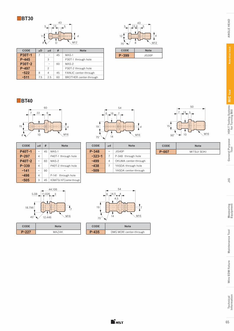
■BT40
CODE φd θ Note
P40Tー1 ー 45 MAS-1
Pー297 4 P40T-1 through hole
P40Tー2 ー 60 MAS-2
Pー339 4 P40T-2 through hole
ー141 ー 90 ー ー498 4 P-141 through hole
ー505 3 45 KOMATSU NTCcenter-through
CODE φd Note
Pー348 ー JIS40P
ー323ー1 7 P-348 through hole
ー499 4 OKUMA center-through
ー438 7 YASDA through hole
ー509 YASDA center-through
CODE Note
Pー227 MAZAK
CODE Note
Pー435 DMG MORI center-through
CODE Note
Pー007 MITSUI SEIKI
15 19
14
16227 7
60 54
6 6
d d
θ 10 M16 M1675° 90°
5
M16
15
10
7
50
13
M1645° 12.446
18.796
35.08 11.02644.106
7 7
M161475°
19
4.56
5414.5 4
■BT30
CODE φD φd θ NoteP30Tー1 7 ー 45 MAS-1Pー445 3 P30T-1 through holeP30Tー2 ー 60 MAS-2Pー497 2 P30T-2 through hole ー522 8 4 45 FANUC center-through ー511 7.5 2.5 60 BROTHER center-through
CODE Note
P ー399 JIS30P
435
8
4
513.4
75°
12
M12
435 513
M12
d
θ D
11
Tech
nica
lIn
form
atio
nW
ire
EDM
fixt
ure
Mai
nten
ance
Too
lM
easu
ring
Equi
pmen
tJI
GG
ener
al P
urpo
se T
ool
HSK-
T To
olin
g Sy
stem
sfo
r Tur
ning
Mill
M/C
Too
l
A
NG
LE H
EA
D
Tech
nica
lIn
form
atio
nW
ire
EDM
fixt
ure
Mai
nten
ance
Too
lM
easu
ring
Eq
uipm
ent
JIG
Gen
eral
Pur
pose
Too
lHS
K-T
Tool
ing
Syst
ems
for T
urni
ng M
illM
/C T
ool
AN
GLE
HE
AD
Ret
enti
on k
nob
65
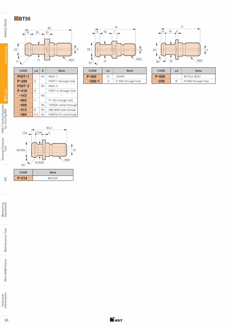
10
θ
10
17
25
d
M24
23
85
75°
85
M24
d
21
18
28
9 774
M24
d
M24
10
65.212.58 57.62
28.956
20.82845°
■BT50
CODE φd θ Note
P50Tー1 ー 45 MASー1
Pー299 6 P50Tー1 through hole
P50Tー2 ー 60 MASー2
Pー419 6 P50Tー2 through hole
ー143 ー 90 ー
ー402 7 Pー143 through hole
ー459 45 YASDA center-through
ー513 8 90 DMG MORI center-through
ー384 5.5 45 KOMATSU NTC center-through
CODE φd Note
Pー400 10 JIS50P
ー288ー1 6 Pー400 through hole
CODE φd Note
Pー008 ー MITSUI SEIKI
ー250 8 Pー008 through hole
CODE Note
Pー514 MAZAK
24
90°
188 5
18
71
Tech
nica
lIn
form
atio
nW
ire
EDM
fixt
ure
Mai
nten
ance
Too
lM
easu
ring
Equi
pmen
tJI
GG
ener
al P
urpo
se T
ool
HSK-
T To
olin
g Sy
stem
sfo
r Tur
ning
Mill
M/C
Too
l
A
NG
LE H
EA
D
Tech
nica
lIn
form
atio
nW
ire
EDM
fixt
ure
Mai
nten
ance
Too
lM
easu
ring
Eq
uipm
ent
JIG
Gen
eral
Pur
pose
Too
lHS
K-T
Tool
ing
Syst
ems
for T
urni
ng M
illM
/C T
ool
AN
GLE
HE
AD
Ret
enti
on k
nob
66
Related Documents