NOTICE OF INTENT TO COMMENCE MINING OPERATIONS KENNECOTT EXPLORATIONS (AUSTRALIO LTD. BARNEYS CANYONPROJECT SUBMITTED TO UTAHDIVISION OF OIL GAS AND MINING KENNECOTT EXPLORATIONS (AUSTRALIA) LTD. 1515 MineralSquare Saft Lake City,Utah 84112 KENNECOTT'S EXHIBIT Docket N Cause No. e o " ,r-*t M-035-009

Welcome message from author
This document is posted to help you gain knowledge. Please leave a comment to let me know what you think about it! Share it to your friends and learn new things together.
Transcript
NOTICE OF INTENT TO COMMENCEMINING OPERATIONS
KENNECOTT EXPLORATIONS (AUSTRALIO LTD.BARNEYS CANYON PROJECT
SUBMITTED TO UTAH DIVISION OF OIL GAS AND MINING
KENNECOTT EXPLORATIONS (AUSTRALIA) LTD.
1515 Mineral Square
Saft Lake City, Utah 84112
KENNECOTT'SEXHIBIT
Docket NCause No.
eo"
,r-*tM-035-009
TABLE OF CONIENTS
PAGE#
Form MR-MO
1
I
224
7
7
7
8
9
99
11L22l
?2
25E262933
vv3539
4L4346{I48
49
51
51
L.4
15
1.6
1.0
3.0
Inboduction
1.1 Locatios
13 l-and Use
L2 Land OwnershipLz.t Srrrf;& OmershioL22 Subsurface Oum'ership
Existing Facilities
Mineral Exploration
Utilities and Accass
Slte Description.
2.1 Geologr2.L.L2.t22.t32.1.4
2.4 Soils2.4.L2.422.43
Qeologrc S-rlti9g .Geology of Mii-eral DepositsSubsurface Geoloqv of Process Farueorogy oI Mtneral Depositslupsryfgce Geolog of Process Facilities SiteScisnicity.
22 Surface Water Hydrologl
23 Groundwater HydroloeY23.1 Regioial Aqlifer Characteristics232 Local Recharse Characteristics233 lncal Aquifer- Characteristics23.4 Bascline Groundwater euality
fiOnicat'Apnroachloil Qpgs ..'Topsoil Quality
2.6 Wildlife
Operation Plan
O
3.1 Description of Mineral Deposits
REVISED 9.29.89
TABLE OF CONIENTSCONTINTJEDo PAGE#
515253
56
56
6263707t
757578787878
80
80
80
81
84
85
9191y2,96
99
102
t02
103
104
104
105
33
3.4
4.4
45
MiniDg32.1322
MiniBg OpcrationsMine Pit Configurations
323 Pit Slope Srability Analltis
CtushingScreening Conveying and Stockpili"g
I*aching3.4.1 l-each Pads3,42 Solution Conrcyances.3.43 Solution Posds
35 Lcach Solution Processine .35.1 Carbon AdsorpEon?5_.? Carbou $trippi"g .1{q Electrowinnidg35.4 Carbon Rsseieration355 Gold Refinl,ag
3.6 AnciUary Facilities
3,7 Waste Disposal
3.8 Production Sc,hedule
3.9 Topsoil Maaagement
3.10 Orcrburden Disposal
3.11 Evaluation of Materials Toxicity
3.12 Runoff and Serliment Control3.r|l Rgnoff !6lrrng Esfim3ggs3.L22 Operational Runoff Control3.123 Operational Scdimcnt Coutrol
3.li} Disnnbcd Acre4ge
Impact Assessment
4.L Surfacc Water
4.2 Groundwater
43 Soil Resources
Critical Wildlife Habitats
Ait Quatity.
REVISED 9-29-89
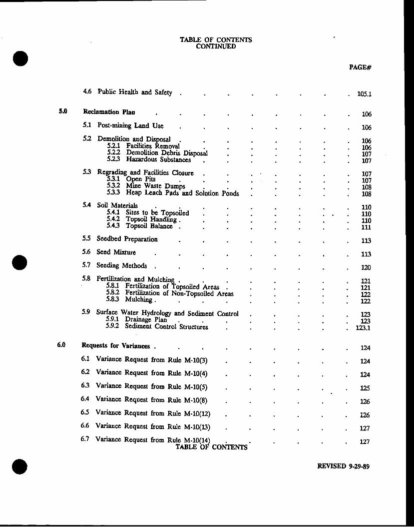
TABLE OF CONIENTSCONTINT'ED
4.6 Public Health and Safety
PAGE#
105.1
5.0 Rcclcnadon Plan 106
106
1061061071ffi
107107108r08
110110u0111
11:}
113
120
72tLzL722122
123L23
12!!.1
LU
7Zl
t2A
125
,26
726
rTl
lIl
5.4
5.1 pssl-rnining knd Use
52 Demolition and Disposal52.1 Facilities Removal5-.22 Dsmolition Debris Disposal523 Hazardous Substances'
53 Rcgra<li"g and Faeilities Closure53.1 Open Pits53.2 Minc Waste Dn'nDs533 Hcap Lcach Pads'and Solution ponds
Soil Materials5.4.1 Sites to be Topsoiled5.42 Topsoil Haadline5.43 Tolsoil Balance-
55 Seedbed Preparation
5.6
5.7
5.8
Seed lvlirure
Seedi"g Metbods
Fertilization and Muuziauon anq MuIcuIIlq .{.q.1 fgltilizafies of Topsoiled Areas
ulchine .
l.q2 Fertilization of No'u-Topsoiled arcas5.8.3 Mulchi'g
Requests for Varianccs
Surface_ W_ate1 Hy&ology 6ad gg.tirnsnt Control5.9.1 Drainage Plan5.9.2 Sedi-eat Control Structures
6.1 Variance Request &om Rule M-f0(3)
62 Variance Request from Rule M-10(4)
63 Variance Requxt &om Rule M-10(t
6.4 Variance Requesr from Rule M-10(g)
6.5 Variance Request from Rule M-10(12)
6.6 Variance Request &om Rule M-10(li})
6.7 Variance Request uo- *urfry,,log?
"o*rrooSREVISED 9.29.E9
oCONTINT'ED
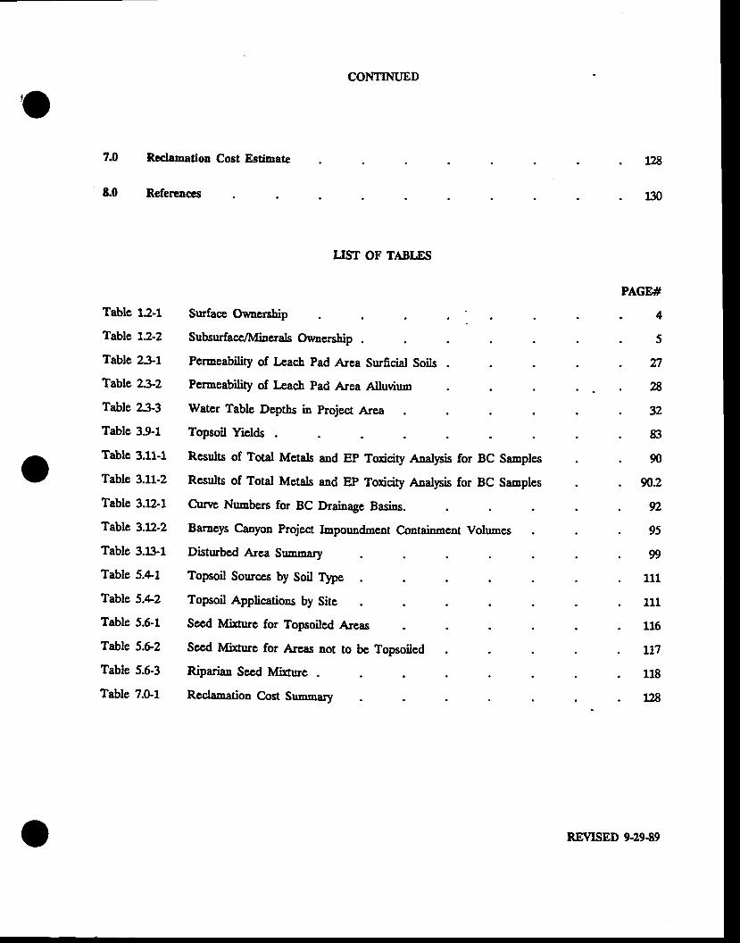
7.0 Recle'-a66o Cost Estimate
LIST OF TABLES
Surface Ouncnhip
Subsuface/Miaerals Owuership
Permeability of Lcach Pad Arca Sruficial Soils
Permeability of l-eacb Pad Area Alluviun
Water Table Deptbs in Project Area
Topsoil Yiel&
Rcsults of Total Metals and EP Toxicity Anal1nis for BC Sanples
Results of Total Metals and EP Toxicity Anal!6is for BC Sanples
Cuwe Numbers for BC Drainage Basins.
Barneys Canyon Project Impoundmenf Q611[einmgst Volumes
Disturbcd {396 grrrrrmar.y
Topsoil Souces by Soil Tlpe
Topsoil Applications by Site
Sccd Mirturc for Topsoiled Areas
Sccd Mixture for Arsas not to be Topsoiled
Riparian Secd lvlirure
ReClamatiOn Qgg[ grrrnrnsry
E.0 Refercncts
128
130
PAGE#
Table 12-1
Table t2-2
Table 2-$1
Table 23-2
Table 233
Table 3.9-1
Table 3.11-1
Table 3.11-2
Table 3.12-1
Table 3.12-2
Table 3.ljl-1
Table 5.41
Table 5.4-2
Table 5.6-1
Table 5.62
Table 5.6-3
Table 7.0-1
4
o
5
n28
32
83
90
902
92
9s
I
111
111
116
L17
118
128
REVISED 9.29-89
oTABLE OF CONIENTS
CONTINTJED
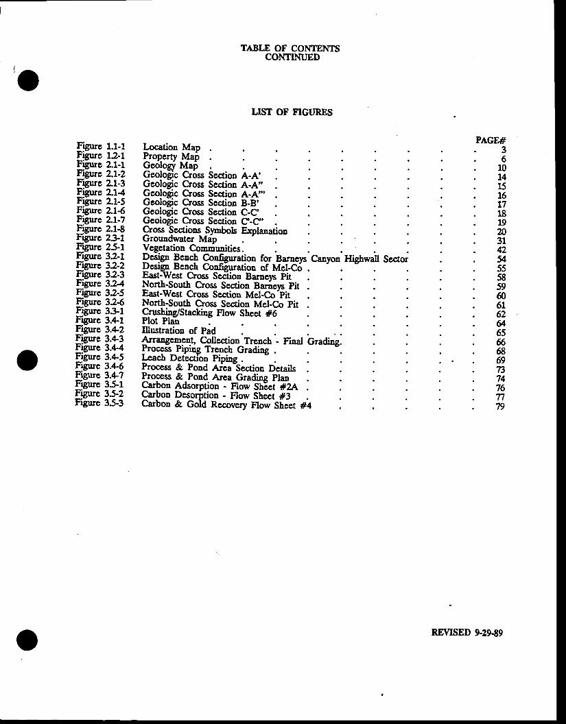
LIST OF FIGI'RES
PAGE#Figrue 1.1-1Figurc 1.?-1Figue 2.1-1Ftgurc 2.1-2Frgrue 2"1-3Ficure 21.{Fifirc 2.1-5Figure 2"16Figure 2.1-7Figure 2.1-8Figurc 231Figuc 25-1Figue 32-1F:rnre 3.2-2Filure 32-3Figure 32aFigure 32-5Figrue 326Figure 331Figure 3.+1Figue 3.42Frgure 3.4-3Filure 3.+aFigurc 3.11-5Figue 3.zt-6Fisure 3.4-7Filure 35-lFigure 35-2Figure 35-3
Location Map 36
10t41516t718192D3142v555859606162&6566869737476n79
Propertv MaiGetitosy lvlaDGeoloSc Crix
Map6i5n ie.tioo A-a'
Gcolo$c Cross Section A-A"Geologic Crms Scction A-A','Geologic Cross Section B-B'Geologic Cross Section C-C,Geologic Cross Section C-C'Cross Sections -Slmbols Expla"ation9roundwatef MdpVegetation Co--unities.Pd1glE*.h 9""!*ation for'Baraeys'Canyon' HghwaU SectoiDesip-Be'lh Configrration of Mel-C6Desip Bench ConfiEuration of Mel,East:West Cross Sedion Barneys pitNorth-South Cross Section Barievs pitEast-West Cross Section Mel-C.o-pitNorth-South Cross Section Mel-Co pitCrushing/Stacking Flow Sheet #6Plot Plai .Illustratioq of Pad*-"ogrg:ol Qfection Treach - nna
-Oraaing.
Process_Piping T1e-nct QlsdingF"d Detection PipingProcess & Pond aieaTection DetailsProCess & Pond Area Gradino PlanCarbon Adsorption - Flow ShEet #2ACarbon Desorption - Flow Sheet #3Carbon & Gold Recovery Flow Sheet #4
o REVISED 9-29-89
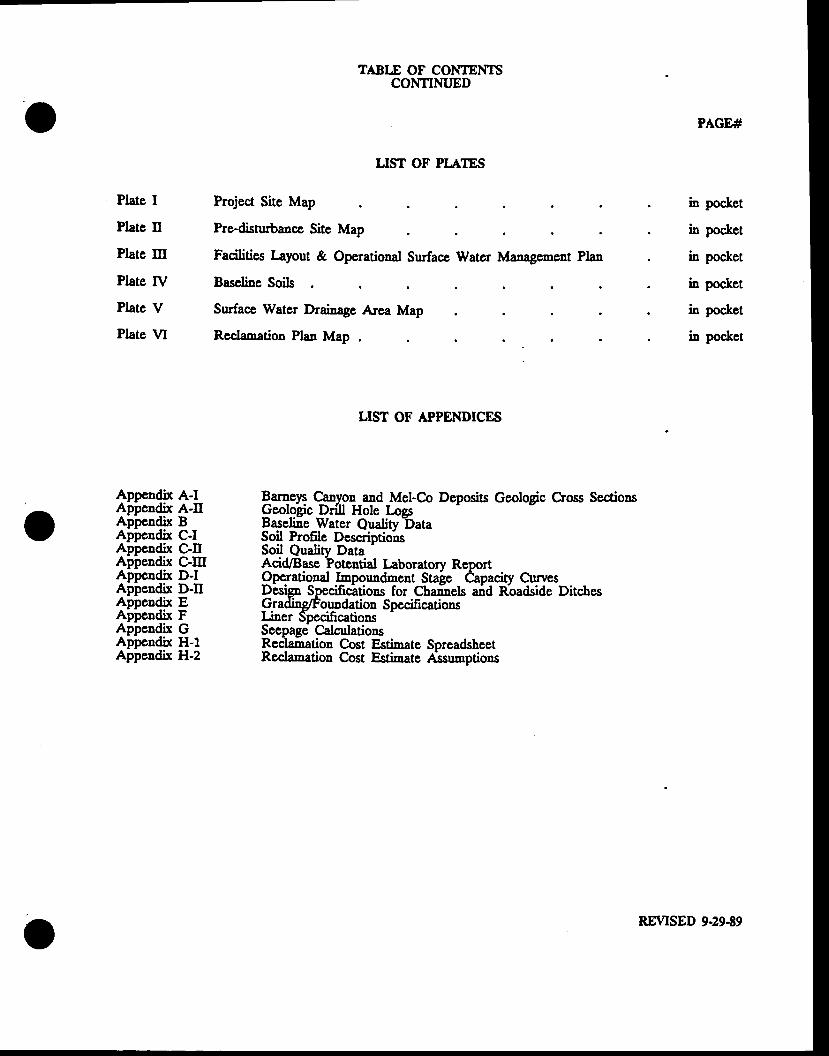
Plate I
Platc tr
Plate Itr
Plate tV
Plate V
Plate VI
Appendix A-IAppendix A-trAppendix BAppeudix C-IAppendix C-trAppendix C-ItrAppcndix D-IAppendix D-trAppendix EAppcndix FAppcndix GAppendix H-1Appendix H-2
TABLE OF CONIENTSCONTINT,ED
LIST OF PI"ATES
Project Site Map
Pre-disrurbaacc Site Map
Facilities Iayout & Operational Surface Water [danegemGtrt Plan
Baseline Soils
Surface Watcr Drainage Area Map
Rcclamation Plan Map
LIST OF APPENDICES
PAGE#
. in pocket
. in pocket
. in pocket
. in pocket
. h pocket
. in poc&et
oEat_oen Canyon and Mel-C.o Deposits Geologic Cross SectionsGeolo$c Dri[ ltole Logslageline _Water Qrrality DataSoil Profle DescriotionsSoil Qualitv Data
'
Acid/Base ?otential l-aboratorv ReoortOperational Imooundment Stale eanaciw CtnesDtsip Specificitions for Chainels and nbadsiae DitchesGrading/Follodation SpecificationsI-i"er SpecificationsScepage CalculationsReclamation C.ost Estimate SpreadsheetRecla-ation Cost Estinate 4tssumptions
..-,
UREVISED 9.29.89
FORM MR-MO(Rev i sed 7 /87)
- a
-2-
Deta i l ed I n fo rma t i on p resen ted i no f f n ten t and app rop r l a te sec t i ons
t h e a b t a c h e d N o t i c ea r e r e f e r e n c e d h e r e i n .
NOTE:
I . GENERAL INFQBMATI0[ (Rule R6t3-OO5-' t04)
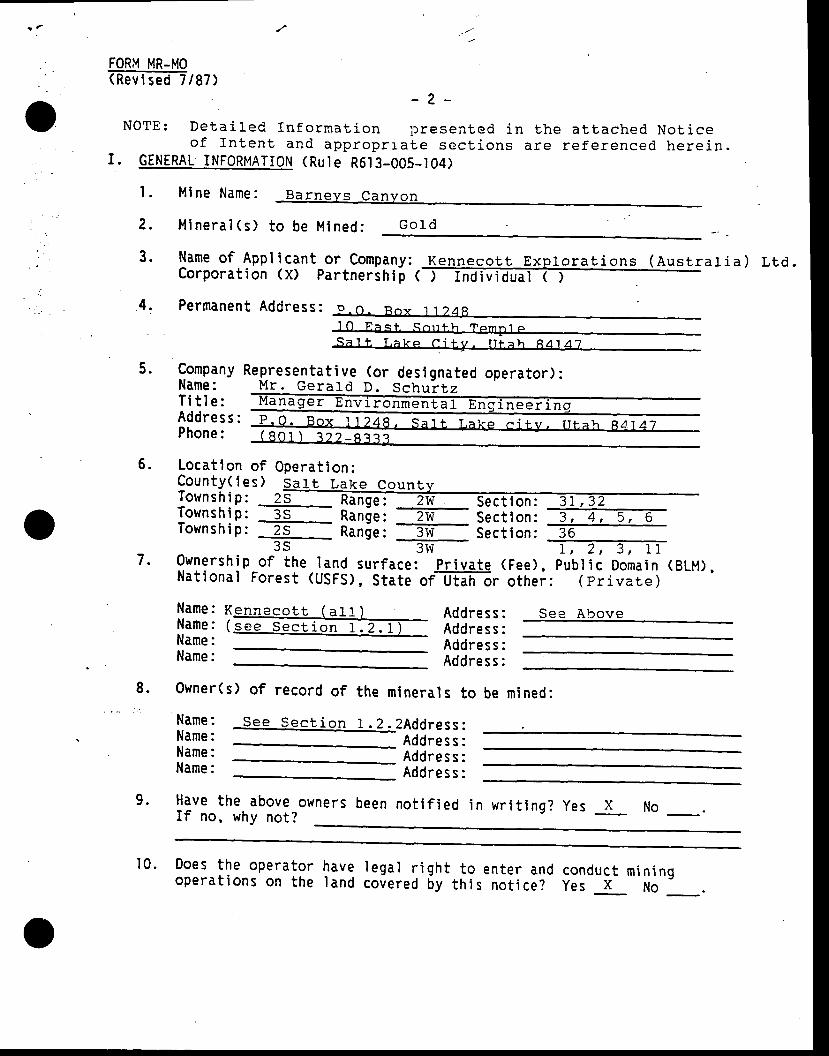
I . M i ne Name:
Minera l (s ) to be Mined : G o l d
Name of Appl icant or company: KenJrego!,! , Explgrat ions (Ausrrat ia) r , ta.Corporat ion (X) partnership <ff i
Permanen t Address : p - r \ - Roy 1 I 48' l
O F a s t S o r r t h T c m F t p
S - a ' l t T , a k e C i t v . I i t a h A A 1 A - 7
2.
3 .
4.
5. CompanyName:T i t l e :Addres s :Phone:
Representa t ive (o r des ignated opera tor ) :_Mr . Gera ld D. Schur tz
5 .
7 .
Locat ion of Operat ion:County ( ies ) sa l t Leke Coun lvTownsh ip : z sec t ion : TTownsh ip : Ran le : Tw Sec t ion : 3 , 4 , 5 , 6Townshto, E- nander -- Section:
-T6---3s ---3w-
1;-Z;-TnOwnersh !p o r the land sur face : p r iva te (Fee) , pub l i c Domain (BLM) ,Nat ional Forest (usFs), state orT[I i i6r other: ( pr ivare )
Name:Name:Name:Name:
K e n n e c o t t ( a l l _ )( s e e S e c t i o n 1 . 2 . 1 )
AddressAddres sAddres sAddres s
See Alrove
8. 0wner(s) of record of the minerals to be nr ined:
See Sec t i on 1 .2 .2Add ress :Address :Address :Addres s :
Have the aboveIf no, why not?
owners been no t i f ied in wr i t ing? yes _x No
Name:Name:Name:Name:
9 .
manager Envi ronmentEl ErJgl lneer in !
10. Does the operatoropera t ions on the
have I ega ' l r i gh tI and covered by
to enter and conductth i s no t i ce? Yes x
min ingNo
FORM MR-MO(Rev i sed 7 187 )
-3 -
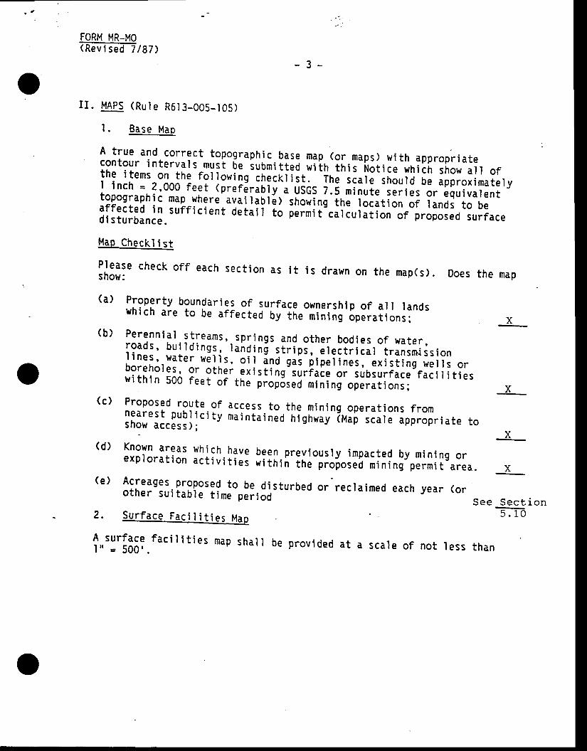
oI I . i , lAPS (Rute R6t3-005- t05)
l . Base Map
A t rue and cor rec t topograph ic .g l tq map. (o r maps) w i th appropr ia tecontour in te rva ls must be submi t tec w i ln ' i r , i t Not ice wh ich show a l ] o fthe i tems on the fo l tow ing iheck t is t . - i f , r " i . . le
shou ld b ; ipprox imate lyI i nch = 2 '000 fee t (p re r6 r i l t v . u i cs z . i r i nu te se r ies -o r -equ iva len ttopograph ic map-where .ua i l iu r i l - s r lon ing ' i t . to . . t ion o f lands to be; i lff:;:,
i n. surri ci ent detair io i.iri t '.. i iur i i ion-or-p.oioseo surrace
P' lease check of f each sect ionshow:
(a) Ploperty boundar ies of surface ownership of a i l rands' 'h ich are to be a f fec t .o -oy i te - tn in ing 'Sp i i . t ions :
(e ) Acreages proposed to be d is tu rbed or recra imed each yearo ther su i tab le t ime p . i i oO-
as i t i s d rawn on the map(s) . Does the mao
X(b ) Perenn ia l t i i : 1Tr , , sp l ]ngs and o ther bod ies o f wa te r ,roads ' bu i ld ings , rand in ! s t r ips , e r . i i i r i i r t ransmiss ionl ines , wa te r w i t i s , ; i i " i no g . r p ipe r ines , ex is t ing we i l s o rboreho l€s , o r o the i e r i s t ing su r face o r subsur face fac i r i t . i esw i th in 500 fee t o f tn . p ioposed min ing opera t ions i x(c ) Proposed rou te-o f access to the min ing opera t ions f romneares t pub l i c i t y ma in ta ined h ighway iu i [ - r . . r . app .opr ia te tos h o w a c c e s s ) ;
" ' r " n s J \ ' ' s F J L q I s q P P r v P r I c r l t
x(d ) Known areas wh ich have been.prev ious ]y impacted by min ing orexp lo ra t ion ac t i v i t i e i
" i i n in the p roposed min ing permi t a rea . x
(orS e e S e c t i o n
5 . 1 02. Surface Faci I i t i es Map
f , , t : t133?. fac i l i t ies map sha l l be prov ided a t a sca le o f not . tess than
[QgM MR-Mo(Revi sed 7 187)
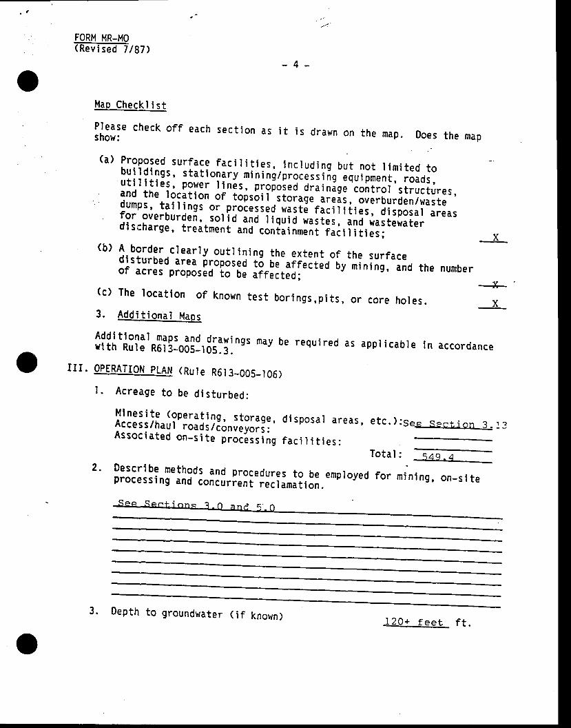
Map Checkl i st
lH: . check of f each sect ion as i t is drawn on the map. Does the map
(a) Proposed sur face fac i r i t ies , . incrud ing but not r imi ted tobui ld inss, s ta t io lyy r in in i rp i ; ; ; ; ; ;s 'J iu ipment , roads,ut i l i t ies , ?gyer r in is , propoi .d dra in ige- iont ror s t ructures,and the rocati :n^9r-toisbi i .storage areas, overburden/wastedumps, ta i r ings or -processed was i i - r i i , i i i i ies , d isposar areasfor overburdei, sor i o inj- i iqr io -r. i i i i
i ' i .o
wastewaterdl s;harge, treatment -anJ-contai
nmeni - i i i i
i i r .u i x
-4 -
d isposa l a reas ,
fac i I i t i es :
etc. ) :see-Sec$.-qn .L 13
:. E,fl---min ing , on-s i te
(b) A border c lear ly ou t l in ing the ex ten t o f the sur facedlsturbed area proposed t6 be af fected by mining, andof acres proposbd lo oe jiri.t.o; the number
+(c) The locai lon of known test bor i ngs,pi ts, or core hol es . x3. Add i t iona l Maos
l f l l ' f f i l : t*[ i ! ]0311,3I: l :nes mav be required as appricabre in accordanceI I I . OPERATION PLAN (Ru le R6. t3_005- l05)
l . Acreage to be d is tu rbed:
Mlnes i te (opera t ing , s to raqeAcces s/haul ' roads / ; ; . ; ; ; ; ; ; ; 'Assoc ia ted on_s i te p ro i i ; ; i ;g
Descr ibe methods and procedures to beprocessi ng and concurrent reclamat ion.
2.Total
employed for
3. Depth to grounduater ( i f known) 120+ f ee t ' ; 1 .
FORM MR-MO(Rev i sed 7 187)
-5 -
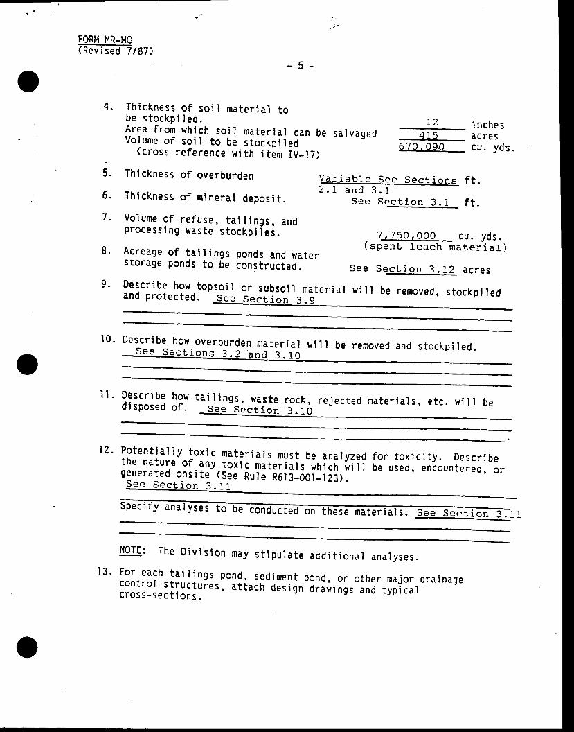
4 . Th ickness o f so i l mater ia l tobe s tockp i I ed .Area f rom wh ich so i l mater ia l can beVo lume o f so i l to be s tockp i led
(c ross re fe rence w i th i t im IV_I7)
5 . Th ickness o f overburden
6 . Th ickness o f m inera l depos i t .
7 . Vo lume o f re fuse , ta i I i ngs , andprocess i ng waste s tockp i ie i .
8 . Acreage o f ta i l ings ponds and waterstorage ponds to be constructed.
sa1 vagedL2 i nche s
475 acres670 .09o cu . yds .
@t ions2 . I and 3 .1
S e e S e c t i o n 3 . i
f t .
f t .
. l r_ lSO , OOO_ cu. yds .( spen t l each ma te r i a l )
See Sec t i on 3 ._12_ ac res9 ' Descr ibe how. topso i l o r subso i l mate r ia l w i l l be removed , s tockp i ledand p ro tec ted . See Sec t ion 3 .9
10. Descr ibe how.overburden mater ia l w i l l be removed and s tockp i red .
I I . Descr i be howdi sposed o f .
ta i l i ngs , was te rock , re jec ted mate r ia l s , e tc . w i l l beSee Sec t ion 3 .10
12 . Poten t ia l l y tox i cthe nature of anygenera ted ons i te
mate r ia l s mus t be ana lyzedtox ic mate r ia l s wh tcn i r i l t(See Ru le RE l3 -O0t - l23 ) .
fo r tox ic i t y . Descr ibebe used, encountered , o r
S e e S e c t i o n 3 . 1
ec i f y conducted
t3 .
NOTE: The D iv is ion may s t ipu la te acd i t i ona l ana lyses .For each ta i l i nos pond , sed iment pond , o r o ther ma jo r d ra inagecon t ro l s t ruc tu ies , a t tach Oes ign d raw ings and typ ica lc ross -sec t ions .
FORM MR-MO(Rev i sed 7 /87)
-6 -
15 .
14 . Descr ibe any proposed e f f luen t d ischarge po in ts (NP0ES) and showthe i r l oca t ion -on the map p rov ided und6r i tu le R6 l8 -oo5-105 .2 . G ivethe proposed-d ischarge ra te and expec ted water gua l i t y . n i i i c r rchemica l ana lyses o f such d ischarge i f ava i f .b ld - rvJu : " . r , io . i s
Vegeta t ion - The opera tor i s requ i red to re tu rn the land to a use fu lcond i t ion and rees tab l i sh a t leas t 70 percent o r i l re p ie r in lng-vegetat ion ground cover (as measured oh si te before mining oi 'ons im i la r ad jacen t a reas i f a l ready mined) :
- - -
The ground cover percentage f igure is de termined by sampl ing andaverag ing the vegeta t ion type( i> on the areas to b i m inbo < ieeattachment I for sampl i ng miltfroOs I .
(a ) Veqe la t ion , Survev The fo ] low ing in fo rmat ion needs to becompte ted based upon the vegeta t ion survey :
Sampl i ng method used See Sect io-n 2 . 5
Number o f p lo ts o r t ransec ts See Seer i on - .5
Ground Cover
Vegeta t i .on (perenn i a l g rass ,Toro and shrub cover)
L l t te r
Rock/rock fragments
Bare ground
Revegeta t ion Requ i rement _ 70 percentor above vegeta t ion f igure)
" t l t ln ln l r : : : r
t4) predominant perenniar species of vesetat ion srowinsSee Sec t i on 2 .5
Perce n t
S e e S e e t i e n 2 . 5
l l I t
l00z
See Sec t i on . 2 .5
FORM MR-MO(Rev i sed 7 /87 )
-7 -
(b ) ?hotograohs^ : .T !e opera tor may submi t photographs (p r in ts ) o fthe s i te su f f i c ien t to show e l i i i i ng -v lge ta t ion
cond i t ions .These photosraphs shourd snow th; ; ; r ; ; ; r ipp. . r inr . ' inocondit ion of the area to be affectid ino may'ue ui i . i i ied forcompar ison upon recramat ion of the i i i . . Ff io i ;g; ; i l ; -snouro be' c lear ly marked as to the loca t io r , o i i in ta t ion and the da te tha tthe p ic tu res were taken.
16 ' So i l s - The p lan sha ' l l i nc lude an o rder 3 So i l Survey (o r s im i la r )and map ' Th is in fo rmat ion is needed to Je ie rmine wh ich so i l s a resu i tab le fo r s tockp i I ing fo r - revegeta t ion . Th i s so i r -Ja t i 'may
beava i lab le f rom the roca i so i r con ie iv ; i i ; serv ice o f f i ce , oF i f onpub l ic lands , f rom the rand management agency . The map needs to beof such sca lg ; f l ra i to r r - i yp . t can be acc i ra ie ry de termined on theground (see a t tachment I ) - . '
(a ) Each so i l t ype to be d is tu rbed needs to be f ie ld ana ' l yzed fo rthe fo l low ing :
0epth o f so i l mater ia lVol ume ( for stockpi I i ng)Tex tu re ( f i e ld de te rmina t ion )pH ( f i e ld de te rmina t ion )
(c ross re fe rence w i th i tem(b) h lhere there^are problem soi l areas (as determined f rom the f ie ldexaminat ion) laboratory analy i is - rav-ue- i . . . r r . ry for some ora l l o f the fo l lowing p i r i r . t . . r ,
Elec t r i ca l Conduc t i v i t ySod ium Adsorp t ion Rat i6Saturat ion 19rg* i c -mat te r percentageAva i lab le PAva i lab le N-NOrpH ( laboratorviTexture ( laboiatory)
S e e Se^ctj-o'J*.4i. nche sr r r r C U . y d S .
1 t
I t t ! I tTr r t r \
_ S e e S e c t i o n ? - 4
l l
NoTE: Soi l samples to be sent to the laboratory for analys is need tobe about one p in t - i ! s iz i , -p ro ier rv . i .o . ieo , " ino in pras t ic bags. Each o f thesoi l hor izons on some s i t6s-mi ! need to be sampred.
nar ra t i ve descr ip t ion o f the georogy o f the area and/or ac ross sec t ion . See Sec t ion 2 .L
17 . Prov ide ageol ogi c
EORM MR-MO(Rev i sed 7 187)
-8 -
V. RECLAMATION PLAN (Rule R6.t3_005_l09)
l . L i s t cu r ren t land use(s ) o ther than min ing : See Sec i . i on I .3
2 , L i s t fu tu re pos t - rec lamat ion land_use(s) p roposed: See Secr i on 5 - .1
3 ' Descr ibe each phase o f rec lamat ion o f the m ines i te in de ta i l underthe fo l low ing ca tegor ies : -
(a) Di sposa ' l o f Trash: :? : tL : . , !? I_9! ] lo lns, foundat ions, t rash and other waste mater ia tswi I I be d i sposed o f .
IV. IMPACT ASSESSMENT (RuIe R6.I3-005.108)
P lease p rov ide a genera l na r ra t i ve descr ip t ion iden t i f y ing po ten t ia ' lsur face and/or subsur face impacts . t ^ lhere app l i cab le , i t t i i descr ip t ionshou ' ld inc ' lude sur face and g ioundwat . r sys i . r r , spec ies o f h igh in te res to r the i r c r i t i ca l hab i ta ts , gx is t ing to i l - i . ro r r . . s fo r rec lamat ion ,s lope s tab i l i t y , e ros ion con t ro t , a i r - l ua r i t y , and pubr i c hear th andsafety.
See Sec t ion 4 .0
(b) _ 9ack f i I I i nq and Grad j nq
uescr r0e equrpment and methods to be employed, amount o f mater ia ls tobe moved and f inar d ispos i t ion o i anv i loc ip i ieo mater ia rs .S e e S e c t i o n 5 . 3
- - - r ' - - '
! . ) So i I Mate r irn o rder to ree :1oep9nJi.;-";-;;mff|lli.3,ni3ii:oi:,:I;'"ll,ll,:i",|::i1yhas to be red is t r ibu ied-on the i reas to be reseeded. i f thes tockp i led so i l i sn ' t su f f i c ien t ro r tn i i , ,o i i ' bo r row a reas w i l lneed to be loca ted .
How much so i l ma. te r ia l i s p lanned to be pu t on the area to bereseeded? i nchesSec t ion 6 .? )
- 9 -
$ lhe re w i l l t h i s ma te r ia l come f rom? S p p S p n l ' i n n s ^ 4 a n r l 5 - 4
How wi ' l l i t be t ranspor ted and spread?
EQSU un-uo(Rev i sed 7 187)
_(d) Seed Bed p1gg1g!Q!Descrite-Ed-T6-e seedbed wi l.t beU S € d . s a o e a a + . i
prepared and equipment to be
( TheDivi sion-JEco6teiEr ipp ing o(e) Seed Mix tu re - L i s t the spec ies to be seeded :
Soec i es NameSeed ing Rate
( ' lbs Pure L ive Seed/Acre)
S p e s p r . t i o n q - 5
i ngin t roduced adaptabt" lp . . i i i -o iprov l de a spec i f i c spec ies I i s t
I l ) Sqedinq Methoduescr ibe method o-p lant ing the
grass , fo rb , and browse seed and w i l li f reques ted)
S g e d . S o a ( a a l- - - - . . - . , . - , , ' i n n R ?
( rhe D iv i s ion -@dr i l l . o r i f h ro^ r r t r : .+ . ^ l , r l , . , - ' L -:_?I i I broadcast sebded, nir io" or rake the
seed w i th a range land or farmv2inch into the soi r.
- i . i i- i ;- in. ' ir l i . l i . i" i ir l" io
(g ) tq r t i I i za t ionDe s c rTE-e-f:-iITilEt i on me t hod a n d r d t€ . See Sec t i on 5 .g
seed I 14 toseed )
<Tn.0 iseeding of Z0O lbs. /acre of -J i i ro ,on ium phoi ;h ; i ;(h ) 0 therReve@tr ot ' f f i i [ t io. proff iT, such as mur chi ng, i rr i gat ion, etc. ,a r e p I a n n e d , d e s c r i b e ' t h e m .
- = o - R o n r i n n i o
at the t ime oI 8-46-0)
FORM HR-MO(Rev i sed 7 187 )
( see tfifif.iti'uu.;o)
Name ( typed or p r in t ) :T i t le o f Opera tor :Date :
PLEAST NOTE:
VARIANCE (Rule R6l 3-005_l I I ) :
4ny p ]anned dev ia t ions f rom ru le R6 l3_005_007Rule R6 l3-005-010 (Recramat ion ' i rac i l ces) must
(Opera t ing Prac t ices)be iden t i f i ed be low.
T i t le /Cateqorv
-10-
vI .
M-10(3) . . r t7 t0ra t , M-10{ rM-10 (4 )u-1 .0 (5 )M-10(12)M-10( 14)
( S e l - e c t e d R r e a s )
5:i, :::1, X:'li:.:.::q::::: g:,.1!.:! "1-Ci;,j yt' ii#,en t des crr b i ns andil ;';l;i;,';: :'i #iTFrix;t h g n e e d f a r f h a r r t r i r a a a r a r r :ll.^:.:!, f?:^!h. vari inci, -ino -ii
;;r;; i rg'iit.i;i; #illlii.;rr;i;l ;il1to be u t i l i zed.
D u r n p - e d E e R o u n d i n oF l i g h r l a t 1 s g r e a t e r t h a n Z 5 d e g r e e s% V e g e t a t i v e C o v e r ( s e l e c t e i - a r e a s )T o p s o i l S a 1 \ ' a g e a n i R e p l a c e n e n t
VI I . SURETY (Ru le R6 l3_005_ l lZ )
A Rec lamat ion sure ty must be prov ided to the D iv is ion pr io r to f lna l approva lo f th is app l i ca t ion- - ln c i i c [ i i t i ng- th i t - . rount ,
the D iv i s ion w i I I cons iderthe fo l low ing major s teps , - - - -
l ) C lean-up-and remova l o f s t ruc tu res .2> Backf i I l ing, .graqi n9 ind coniorr ing.3) Soi l mater iar- redis I r iuut ion and stabi ' r izat ion.1l Revegetat io l (preparat ion, seeding, mulching)11 Safety ano renl in i .6) Mon i to r ing .
To ass is t the D iv is ion in de termin ing a reasonabre sure ty amount , p leaseat tach a rec lamat ion cos t e i i im i te r [ i ch add ie i ies eacr r 6 r tne above s teps .VII I . SIGNATURE REQUIREMENT
I hereby cert i fy that the foregoing is t rue and correct .Signature of 0perator:
r r .n ;
Sec t ion 40-8-13(2) o f the Mined Lan.d Rec lamat ion Ac t p rov ides fo rmai n tenance o f con f i dent i a r r t y -con; ; r ; ; ; ; - ;e r ta i n por t ions o f th i srepor t ' P lease check to see tha t any in io rmat ion des i red to be he ldcon f iden t la l i s so labe led and inc lu led 'on ' r .p . r . te shee ts o r maps .Slirol,lilT::g fi
,:3;l?,:;,ili ioiiiioit ;i.; ;;_n;;;;;.oi tn;.;;oo,i tconf ident ia r In fo rmat ion Encrosed: (x ) yes ( ) No0899R
LO INIRODUCIION
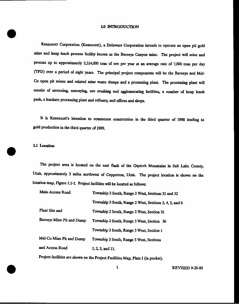
IGnnecott Corporation (IGnnecott), a Delaware C.orporation intends to operate an operr pit gold
rnins lad beap leach prooess facility known as the Barnep Canyon mine. The project q,ill mins and
process up to approximately 4314,000 tons of ore pcr ),ear at an average rate of 2,000 tons per day
CntD) over a Period of cight years. The principal project components wiu be the Barneys and Mel-
Co open pit mines and related mine waste dnmps and a processing plant. The processing plant will
oonsist of screening conveying, ore cnrshing and agglonerating facilitieg a number of heap leacb
pads, a leachate processing plant and refnery and offices and shops.
It is Kennecott's intention to commence constructioD in the third quarter of 1988 leadiag to
gold production in the third quarter of19g9.
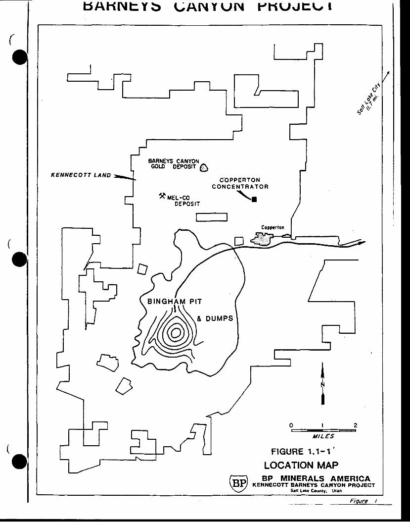
Ll location
The project area is located on the east flank of the Oquirrh Mountains in Salt Lake County,
Uta\ approximately 3 miles northwest of Coppertoq Utah. thc project location is shorm on the
location -ap, Figure 1.1-r. project facitities wiu be locatcd as follows:
MainAccessRoad To*aship 2 South, Range 2 West, Sections 31 and 32
Tomship 3 South, Range 2 West, Sections 3, a, 5, and 6
Plant Site and Township 2 South, Range 2 Wes! Section 31
Barnep Mine Pit aad Dump Township 2 south, Range 3 west, section 36
Township 3 Sout\ f,ange 3 West, Section 1
Mel-co Mine Pit and Dump Tonmship 3 sout\ Range 3 west, sections
and Access Road 1r13,and 11.
Project facilities are showu on the ptoject Facilities Map, plate I (in pocket).
1 REVTSED 9-29-89
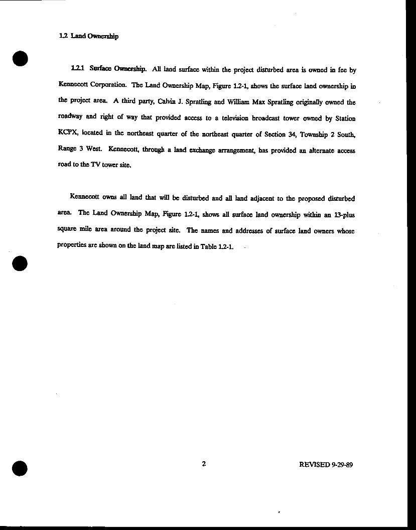
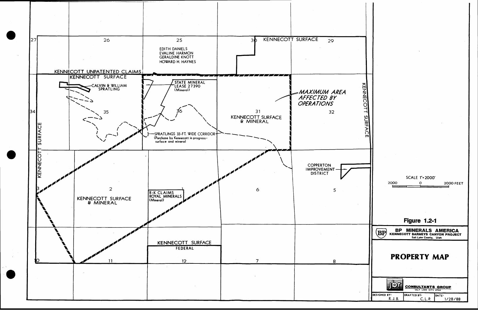
L2 LandOcrncrship
l"J Surhe Omcotttp. All land surface within the project disturbed arca is ocned in fee by
Kconccott Corporation The r -"d Onmership Map, Figure 12-1" shows the surface land oumenhip in
the project area. A third party, Calvin J. Spratting and William Max Spratling originaly oumed the
roadway and right of way that provided acoess to a television broadcast tower owned by Station
KCP& located in the northeast guartcr of the northeast guarter of Section 34, Township 2 Sout\
Range 3 West. Kcanecott, through a land exchange atrargemert, has provided an alternate acoess
road to the TV tourcr site.
IGnnecott oums all land that will bc disturbed and all land adjacent to the proposed distubed
area The l-aad o*aership Map, Figure 1?-! shoun all surface land owucrship within an lii-plus
square mile area around the prqiect site. The names and addresses of surface land o*uers whose
properties are shown on the land map arc listsd in Table 1j-1.
2o REVISED 9-29-89
6Al-tNts, Y 5 UAN Y UN F'F{tJ.rtr \, I
s$
Jo
KENNECOTT LAND
EARNEYS CANYONGOLD OEPOSIT
1l uel-coDEPOSI
C-OPPERTONC O N C E N T R A T O R
\rT
tI
UILES
FtGt fRE 1.1-1 '
LOCATION MAPBP MINERALS AMERICA
KENXECOTT BARI{EYS CANYOI{ PROJECTS.|t l*. County. Utrh
GHAM P IT
6\BIN
Fioure I
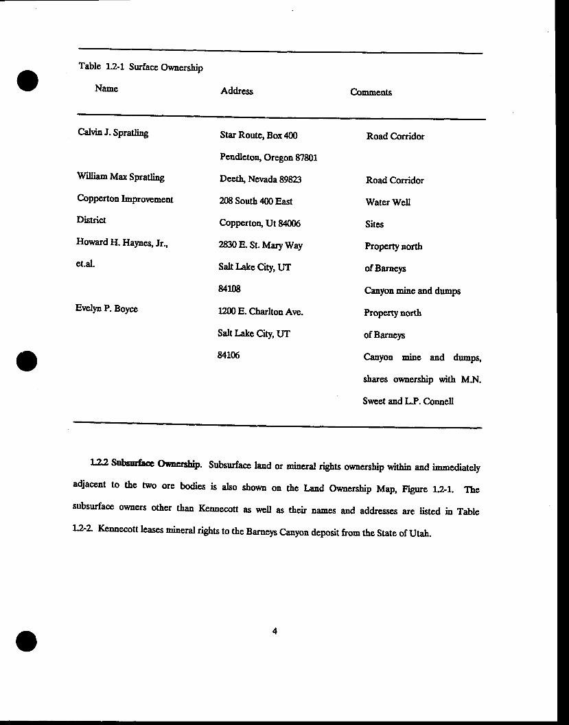
Table 1.2-1 Surface Ownership
Name Address Comments
CdvinJ. Spratling
V/illiam Max Spratli4g
Copperton Improvement
District
Howard H. Halmes, Jr.,
et.al.
Star Route, Box 400
Pendleto& Oregon 87801
Deetb Nevada 89&23
208 South 400 East
Copperton, Ut 84006
28308. St. Maryway
Salt Iake City, UT
84108
1200 E. Charlton Ave.
Salt Late City, UT
84106
Road Corridor
Road Corridor
WaterWell
Sites
Property north
ofBarncys
Canyon mins snd dunps
Property north
ofBarneys
Canyon mine and d*pr,
sharas oumership with M.N.
Sweet and L.P. Connell
Evelyo P. Boyce
122 suMce owocnstb- subsurface land or mineral rights onnership within and immediately
adjacent to tbe two ore bodies is also shown on thc Iand Ow.nership Map, Figure 12-1. The
subsurface owners otber than Kennecott as well as their nanes and addresses are listed iD Table
l'2'2' Kennecott leases mingpt rights to the Barneys Canyon deposit from the State of Utah.
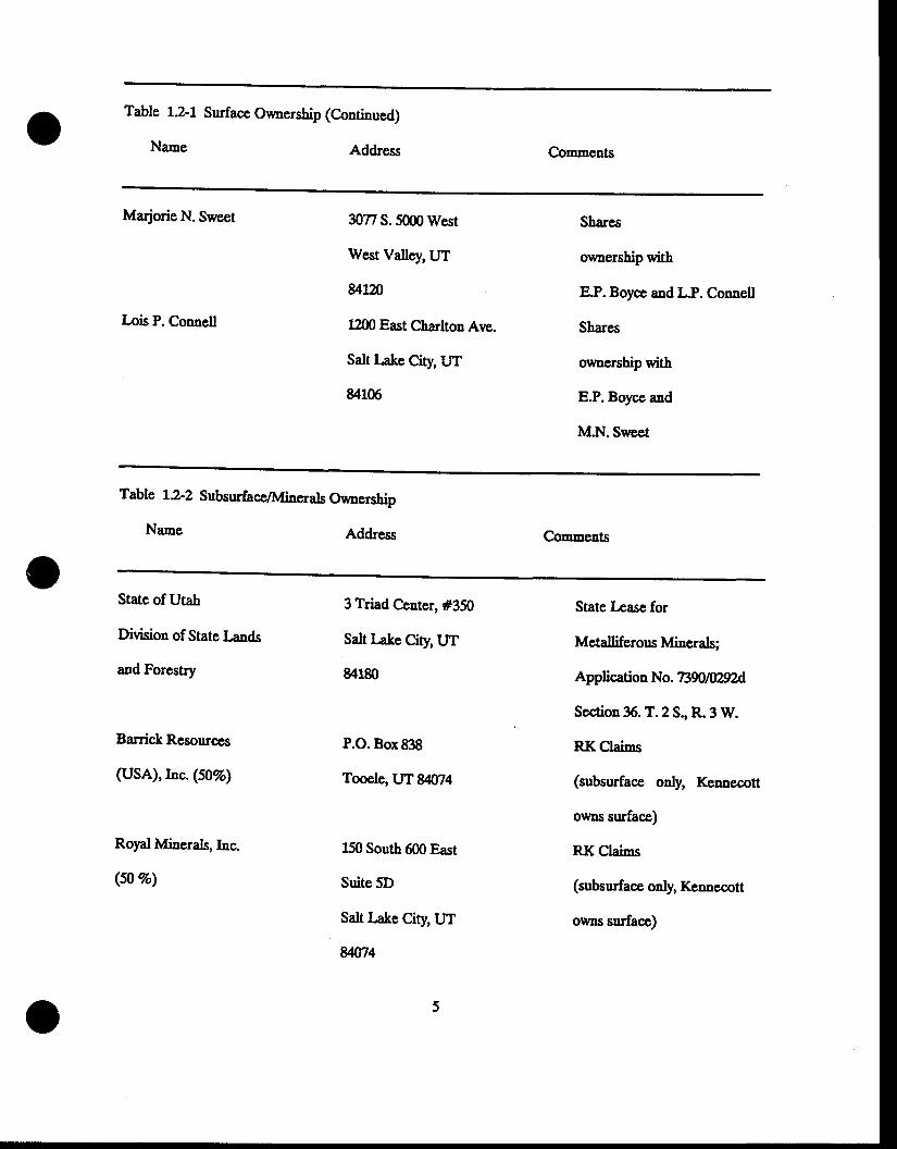
Table 1.2-1
Name
Surface Owaership (Continued)
Address Comments
Marjorie N. Sweet
Lois P. Connell
3O77S.5000Wsst
West Valley, UT
u12n
1200 East Charlton Ave.
Salt Iake City, UT
84106
Shares
ownership with
E.P. Boyce and L.P. Connell
Shares
ownership with
E.P. Boycc and
M.N. Sweet
Table t2-2
Nrme
Subsurface/Minerals Oumership
Address Comments
State of Utah
Division of State Irnds
and Forestry
Banick Resources
(USA), llic. (50Vo)
Royal Minerals,Inc.
(s0 vo)
3 Triad Center, #350
Salt Lake City,IJT
84180
P.O. Box838
Tooele, UT84074
150 South 600 East
Suite 5D
Salt Iake City, UT
8/074
State Lease for
Metalliferous Minerals;
Application N o. 73XJ N29?A
Scction %.T.2S., R.3 W.
RKClaims
(subsurface only, Kennecott
olvls surface)
RK Clains
(subsurface only, Kennecott
owns surface)
EDITH DANIELSEVALINE HARMONGERALDINE KNOTTHOWARD H. HAYNES
TT UNPATENTED CLAIM
KENNECOTT SURFACE 2e
EIF 1'Tl
om
'MAXill4Ull4 AREAAFFECTED 8YOPFRATPNS
KENNECOTT SURFA
VIN 8 WILLIAMSPRATLING
--. 35( - -5
\ l( / - - l
\ 7
31KENNECOTT SURFACE
8 MINERAL
- - _ _ _Uu-e.ftn
F.F
STATE MINERALEASE 273e0
/
(M inero l )
{u--\-: . - r l
t \
FSPRATLTNGS 33-FT. wrDE coRRlDoR(Purchose by Kennecott in progress-surloce ond minerol
COPPER,TONIMPROVEMENT
DISTRICT
2
KENNECOTT SURFACE8 MINERAL
R.K CLAIMSROYAL MINERALS(Minerol)
BP MINERALS AMERICAKENI{ECOTT BARNEYS CANYON PROJECT
KENNECOTT SURFACE
PROPERTY MAPFEDE RAL
t / 2 8 / 8 8
scALE r.2000'2000 0 2000 FEET
Figure 1.2-1
o
13 LaadUse
The lands in the project site are patent lands uader the control of Kcnnecott. The principal
land ue at the project site-proper has been for wildlife habitat. The areas that will bc developed
are ctrreutly undeveloped and wildlife usage is relatively high, slthsngh reccut exploration activity
has undoubtedly caused at least local changes in the level of wildlife usage. The wildlife in the
area is discussed in Section 2.6. The lands are presently closed to public aocess and, consequently,
little hunting occurs bere. Thqse lands also are leased for livestock ganng. An access road
through the property allows access to the KCPX TV tower on the ridge adjacent to Harkers Canyon
(Plate I). I-and adjacent to the curent and future project aocess road is under cultivation for
wheat.
L4 F isfingFacilities
The locations of existing roads are shown on the Project Facilities Map, plate I and the pre-
Disttubance Site Map (Plate II). There are no builrlings, lakes or reservoirs within the project area
or within 500 feet of it. The locations of streams, springp, and wells are discussed in Sections 2.2
and 2.3. Powerline locations are shown on Plate II, the Pre-Distrubance Site Map. There are no
other &'ansmission lines in the project area. There are oo existing mine aditg entries or open pits
in the project area.
15 MincralEploration
Kennecott commenced minslxt erploration on the project in 1981, with ddling begiming in 19g5.
A total of 215 ex.ploration drill holes ranging in depth from 35 to g76 feet were &illed using rorar!
reverse circulation and diamond core drilling machines. The Pre-Disturbancc Site Map, plate II,
shows the locations of e':rploration drill holes outsids ths n'ing developmcnt areas. This map is
Coofidential. The locations of exploration drill bole.s haw also been provided the Division in
previous submittals of oqploration Notices of Intent. Areas of more intensive dd[ing at the sites of
the proposed open pits are outlined on that map. All drill holes have been or wilt be plugged
according to regulationg unless they have been completed as piezometers as discussert in Section 2.3.
In addition to drilling, a number of trenches were dug with a backhoe, and access roads for &iling
equipment were built with bulldozers. Other exploration work consisted of geologic mapping and
sanpling.
15 UditiesandAess
The entire plant site, warehousg and truck shop will be supptied with electricity from
Kennecoft's Utah Copper Division. The Facilities Layout and Operational Surface Water
Menagement Plan map, Plate III, shows the location of the proposed powerline. Propane for heating
wiu be supplied to the site via truck. Telephone service will be supplied by Mountain Bell.
Telephone service will be brought to the site via either the powerline or aocess road corridor.
Access to the project area will be via an inproved aooess road from Highway €, s shown on
Plate I. The principal access to the Mel-Co mine pit and crusher wil be via a graveled road
planned to be constructed from Barneys canyon along the route shorm on plate Itr.
R"EVTSED 9-29,89
2(} SitcDcsaiptio
21 Gcologr
e r r Goologicscdng
The Barneys Caayon projc€t arca is located at the cast edgp of the Palcozoic core of the
Oquirrh Mormtains. The surficial gcolog of the prqiect area is sho*n oa Figrue 21-1. The
Oquirrh Mountains are comlrcsed principatty of Pennsytranian and Psrnian miogeodinal sedimentary
roels with an aggregate thickness of morc than 35,000 feet. 'Ihe principal rock typcs are limestoncs
and sandstones that wpre depositcd cydically.
The Barnep Caayon and Mcl-Co.ioe prt sites are underlain by thc Permian Kirkman-Diamond
Creck and Park City Fornations. These units are moderately to stecply dipping in directions rargiqg
fron northwest at Mel-Co to north and aortheast at Baraeys Canyon Stru*urdly, the Kirknan-
Dianond Peak Formation is patt of the footwall platc of thc Oquinh thrust fault (Figrrc ZL-L).
The Park City Formation oocurs at thc cast side of the Barneys Canyon deposit and has been
preserved in a down-faultcd block of the uppcr plate of the Oquirrh thrust fault (Swensen, 19/5), as
shoum on the gcologic map (Figpre Z1-1). In addition to thc thrusting; the Paleozoic rocks have
been faulted by a number of northeast and north-trending higb-angle normal hults @grre Lt-L).
The projcct procass facilities will be sited on Quaternary allwial sediments to the east of tbe
bedrock outcrop tine. The Pleistoccne Har&ers Formation alluvium is the dominaat alluvial tlpe;
howevcr, recent stream allwium occupies stream c,hannels. lbese alluvial t5pes ate not
difrersntiated on the geologic "'ap, Figue 21-1. Tertiary volcanic rocks, compriscd chiefly of
latitic floursr brccciaq and agglomerates crop out to the north and south of the process facilities.
- -REDACTED- -
ORIGINAL IJOeATED IN Doclt COIIFIDENTIAL FILE
2.1-1
G:n BP iilNERAIS Ar'tERtCA\E n KEI|ilEGOTT BARilEYS GAt|YOil PROJECT\-/ s.tt L*. coudn ut.n
GEOLOGY MAP
YTEE COT T'LTAIITS OFOUP- f f i
) !S|GN€O EY: IDIATIED rYr lo^I f :R.J .8 . . 1 cL .P I t / 26 /88
The Quaternary alluvium in the process area unconformably overlies the buried volcanic rocks.
t't ' GGolAg'/of ttfincralOePcits
The Barnep and Mel-C-o ore bodies will be dercloped as fiilo separate open pits. The Barnep
ore body is hosted by the lower Permian Part City and Kirkman-Dianond Creek Formations. The
host roc& litholog consists of silty dolomite with chert interbcds and calcareous sandstone,
respectively' in the two stratigraphic units. The gold-nin e:rlliz?A zole in the Barnep deposit has
bccn completely oridized aad cssentially ao sulfide minerals are prescnl The deposit is
characterizcd mineralogically b the presence of clay minerats which are hydrothermal alteratioa
products" The overburden at the Barneys pit will be comprised of dolomite with chett interbeds
and sandstone' strata dip gently to the north and the naximum ore depth is approximately 600 fect
in the northern part of the ore body. structurally, the dcposit has been faulted by both a low-
angle tbrust fault and a aumbcr of high-angle norual faults. The geologr of the Barneys deposit is
depicted in cross section on Figure A-I-1 which can be found in Appendix A-I. The conteats of
AppendixA-I is confidential and is therefore bound separatelyfrom the nainbodyof this document.
The Mel'co ore body, locatcd approximately 15 miles southwest of the Barneys deposil is
hosted alnost cathely by calcareous sandstoncs of the lower pennsytranian Kirha&Diamond &eek
Formatiou' Unlike the Barncp dcposit, the Mel-co ore body hrs not bccn completely oxidized and
sulfide ore, characterizcd by the prcs€noe of pyrite and marcasitg oocurs in the deeper parts of the
ore body' overburden at Mel-co will consist of sandstone and quartzite. The strata hostiag the
ore body are vertically or near rartically dipping the geolog of the Mel-co deposit is shoum in
cross section oa Fig're A I-4 crhi.h can arso bs found in Appendix A-I.
11
e.r q Subsurh€ ereoQg of the pr,oess Facilities Site
The p,rocess facilitie.s site is outtined on the geolqgc -ap (Figure LL-L). Dri[ing has been done
in the process site area both for the purpose of condeunation (determination that economic mineral
deposits arc not presenQ and foundation te.stin& The locations of these drill holcs and boriags are
sho*n on Plate tr and geologic logs are prcsented in Appeodix A-tr. Condemnation driling by
KsDnccott in tbe procoss plant area has consisted of threc rotary-rer€rse circulatioa &ill holes.
Geologic logs of two holeg BC-!E and BC-150 are arailable. Foundation investigation studics by
Sergenl Hauskins, and Beckwith (SIS) led to the drilling of a numbcr of test borings and test pits.
Thc locatiou of the dcepcr augcr borings are also showa on Plate tr. Additioaal geologic data
oomes from logs of water supply wclls in tbe area The locations of water suppb wclls uscd in
qraluating the site geologf are shown on Plate tr, the Pre-Distubancc Site Map. Sourccs of
grounduater information for the area are discussed in section 23.
No faule or other geologic structures have becn identified by the linited amount of drilling that
has been done in the process site area Mapped geologic structures in the Permian-aged bedrock to
the wEst of the site @gure 2.1-1) are not Lnovm to have been active since the mid-Tertiary or
before.
A number of geologic cross sections tbrough the proposed process facility area have been
prcpared rsi'g available gcologic log!. Tte lines of section are shocm on Plates I and tr. The
sections are show! on Figures ?^t-2 thtols 2"L-7. The scales, both vertical and horizonta! of the
sections are rariable depending on the leogth of the section and topographic retief along the line of
section Hence in rnalring direct comparisous between sections, the effects of scale chaDges must be
taken into account. the c':planation for thc spbols used in the cross sections is shoqm on Figure
z1-8.
12
Cross sections A-A' (Egtrre Ll-Z) atrd A-A' (Figrre 21-3) are northwest Estrding scctions
drawn thtongh the process site condemaation holes and then Eore thnn a mile southeast of the site
through wells K-405 and W-32, respectively. The lines of section for each of thcse cross sections
are shourn on Plate I. Well K-405 is a lGnnecoff water production well &illed adjaccnt to the aew
Co,ppcrton Conccntrator. Well W-32 is one of the two Copperton comnunity watcr supply wells.
These soctiors sbow that the allwial deposis near the project site were deposited on a pedinent of
uderlying volcanic rocls and that ths dominant bedrock in tbe area is Tertiary volcanic flour.
These sections also depict the aquifcr t!'pes in the project area In dril holes BC-148 ald BC-150,
the occurrence of clap identified in the rotary drill ortting are interpreted to represent air-fall
ttttr beds. In each drill hole, the groundwatcr surface is closely associated with a tuff-derived clay
layer. As discussed in Section 23, hydrogeologic data suggest that tuff beds in the volcanic flow
scquence scrvg at least locally, as confiningbeds or aquitards.
The geologic log of wcll W-32 desaibes volcanic roc\ prosumably Tertiary io age, ovcrlying
clay-dominant sediments described 3s hke bed sediments and presumably of Pleistocene age. The
nost reasonable e':rplanation of this incongnrity se€Drs to be that the volcanics were deposited on top
of the apparent Lakc bed sediments by a debris flow or other mass mowmcnt. The dcscription in
the log of "rockc in mud" within oocrulencc intcrval of the rctcanic rocts supports this contention"
Goss scction A-A"' @gure 2.14) is a northwest-trendiug section that cfcnds across the cntire
procqss area. Agai!, the relationship of the ground water surface to the volcanic tufr layers in the
volcanic 0oun is apparent. Becatse the coademnation holes were drilled by a rotary dri[ detailed
logs of the uncossolidated allwium were not prcpared- The logr of the auger holes arg as a result
of the drilling metho4 more detailed. Attempts to correlate atluvial lithologies between foundation
a
- -REDACTED- -
ORIGIIIAL LOCATED III DOGU COIIFIDENTIAL FILE
te 2.1-2lfrl BP MTNERALS AMERTCASz
xElr*Ecorr 3ii$:L?ilrrolr PRoJE*
CROSS SECTION A.A'
COXSULTATTS OROUP
ott 'onto "o., 'B' lot^tt* '
t*-Ti i i-3r /88

- -REDACTED- -
ORIGINAL LOCATED IN DOGU CONFIDEI{TIAI. FII.E
Ffgure 2.1-3r-\ BP MTNERALS AUERICA\^lty KElrxEcoTT BARLEYS CAr|yOlt pRoJEcTV S.tt !rL. Ccnty. Utrh
CROSS SECTTON A'A''
coraaulTAl{Ts oBOUP
) E S I G N E D 8 Y , I D R A F I € 0 8 Y ' l O e r t ,R.J .B . I c . r_ .p . I t r3 r l88
- -REDACTED- -
ORIGfNAIJ LOCATED IN DOGU CODIFIDEIITfAL FILE
Figure 2.14
/-;\ BP MTNERALS AMERTCA\Drl KEXNECOTT BARNEYS CANYON PROJECTV Sall Lake Conrv, Utrh
cRoss sEcTloN A-A"'
COXSULTAXTS GROUP
DESIGNED 3Y: IOTAFIED rr" IOeir i-R.J.B. l c.r_.p. 1 r /3o/88
- -REDACTED- -
ORIGINAL LOCATED IN DOGU CONFIDENTIAL FILE
BP IUIINERALS AMERICAKENTIECOTI BARNEVS CAXYO'I PROJECT
Srlt L*. Cqlnly, Ut.h
CROSS SECTTON B-B'
- -REDACTED- -
ORIGINAL LOCATED III DOGM COIIFIDENITIAL FILE
BP MINERALS AMERICAKEXXECOTT BAR}IEYS CAIIYO}I PROJECT
S.tt Lrk. Co|J||ly, Utlh
cRoss sEciloN c-c'
COTAULTAXTA OROUP
D I A F T E D B Y :C.L.P
- -REDACTED- -
ORIGINAT LOCATED Il{ DOGU CONFIDENIIAL FILE
2.1-r-\ BP MINERALS AMERICA\Df/ KExlrEcorr BARNEYS cAllvox PRoJEcr
\-/ Sall Lal" Counly, Utah
cRoss sEcrtoN c'-c"
9jCl corsulTAxrs eRoup- - f f i
D E S I G N E D 8 Y . I D R ^ f I E O 8 Y . I D A T E 'R . J . B . I C . L p . I \ / 3 O / B B
- -REDACTED- -
ORIGINAL LOCATED IN DOGM COIIFIDENTIAL, FILE
Ffgure 2.1-8I-I BP MINERALS AIIERICA\Dr/ KEr0rEcorr aARrEys caltyor pRoJEcT\-/ sdl l-.tc cqfrtv. ut.h
cEorocrc cRoss sEcnoNSYMBOLS EXPLANATION
D € 5 | G N € D g Y , I D R A F T E D 8 Y , l D ; - ER . J . B . I C . L P | 2 / 8 / 8 8
borings were made, as the section shouas; however, the drill hole density and variability in
lithologies ma&es suc.h interpretation difficult. It is rignificsjt that of the seven borinp depicted
on Section A-Ar" (Figure LL4), fir'e have clay as their uppermost lithologr. Each of these firre
borings are located on hilltops 6r hillsidss. This relationship is displayed in most bori1gs sinilarly
located in the process site area
Goss section B-B' (Figure Zl-t is a northeast-trending section through the wpstern-most
proposed leach pad site.
Cross sectious C'C (Figure 216) and C-C' (Figure 2.1-7) are, raspectively, aorthurcst and
northeast-trending sections in the area of the eastern-most leach pad sites. AgaiD, as was the co.e
in scction A-A'" (Figure 2.14),lithologic correlation bctween drill holcs is difficrttt The geologic
oacurreDae of very minor pcrched grouldwater is depicted in these cross sections. This pere,hed
grormdwater is discusscd frirther in Section 23.
ZLa Scisnicity
The site is located near the eastgrn boundary of thc seisnically actirr Basin and Range
Province. Regional scisnicity maps have bcen compiled for Utah based on historic data from 1g50 to
1980 (SHB' 1988). Small to modcrate sized carthquakes are numerous in the State and are largcly
associated with the wasatch fault zonc and Basi', and Range faults such as those on the west side
of the Oquinh Range. The closest recorded earthquake was a 1962 rnagnituds 52 errcnt in Magna
approximately 9 miles north of the site.
TVo mapped fault sptems with Holocene activity are aear the site. They are the Wasatch Fault
about 16 miles to the eas! and the frontal fault of the oquinh Range about 5 miles west of the
2L
site. Tte seisndcity in &e Mrgna area suggests the possibility of active faulting; however,
interpretation of low-sun anglc aerial pbotograpbs and aerial infrared photography indicate that
there is no surface rupture in the Magna area (SHB, 1988). This has been interpreted as evidence
that there have been ao events larger than rnagnituds 6.0 near the site area during the late
Quaternary.
The site does lie within the UBC-3 seisnic zoac and nerinurn credible earthquakes for ranious
faule in the area have been calctrlated The estimated horizontal bedroc& acceleration resulting
from a Daxinun credible carthquatc of Magnitude 7.6 fot the Wasatch Fault was ued for the
projcct site. An effective pcat horizontal ground accslcratioa of 0.189 (corresponding to a 500 year
resurreuce inter%l) was used for the carthquakc desigg evaluation The earthquake de"ign
eraluation indicated that permanent deformations rmder this design accelcration value would be lcss
than sh inches, which is cousidcred well within sxfe lirnits. It was also determined that major
earthquakes generating accele'rations of 02g to 03g would probably create slides of sufficient 'nars
is dqmage the pad liner. lte rectrrcnce interyal of these events is estimated at 600 to 1200 years;
thug a *nnll fi5ft of earthquake-induced liner damage is inherent with &e use of heap placemeut by
dumpiag (SHB,1988)
22 Surfae Watcr Hydrotqgr
The mean annul precipitation in the Barncp Caryou project area is 16 inches @amcs and
Moore, 1988). Approxinatd one third of the prccipitation fails 6s snow from December throryh
March and the remainder falls as rai4 predominately in the Spring. Summer precipitation is largely
characterized by thunderstoros influenccd by the orographic effects of the Oquinh Mountains (SCS,
194). Auual snowfall along the Oquirrh Mountain foothills is approximately 81 inches @anes and
Moore,1988).
2
Surface water drain4ge around the Barneys Canyon and Mel-Co Mine site project areas is
governed by the north-south trending Oquirrh Mountains. these mountains rise to an elevation of
9,fi)0+ feet AlvlSL (aborn mean sea level) or approximately 5,000 feet above the 4300 fcet AIT{SL
SdtkteValley.
The Barnep Canyon Project site lie.s alo4g the southeastera flanlr sf the Oquinh Mountains.
Baraep &eeb which floun from Barnep Canyoq is intcroittent at is headwaters and perennial
over a two mile reach adjaceat to the project area. Directiol of flow is from west to east where
runoff contributes to the Jordan Rivcr located roughly fine milcs away. Continuors stream gadng
has 16vg1 been performed on Baraep &eek Other cnall, intermittent and ephemeral drainages in
the project arca are localized by the topography of the Barneys Canyou project site which consists
of low hils sloping easterly at a gradient of about l0%. Elevatiors range from 5200 feet to 2000
feet alo4g these foothills. Many s-all valle],s witb watershed areas less than one square mile nrn
tbrough the site. Becarse of their smal drainage areag runoff from these cphemeral channels is
srnnll
Bancroft Spring ernanates in the srnell rnalley south of &e proposed leach pad area @late 2) and
provides a souroe of flow in that drainage for a part of the year. Only during very dry periods
does Bancroft Spring cease to f,ow.
The Mel-C-o pit site is located on the draiugc divide (eL ?6ffi top) south of Barncys Canyon
and at the head of a snall tributary to Dry Fork Dry Fork is ephemeral and the nmoff from the
watershed drains iils f,inghern Creek approximately two miles south (Figrne 1.1-1). The Mel-Co
umste dump will lie on the southeastera edge of this ridge approximatety 25fl) fect southeast of the
pit area Water frqp fhis s1.e6 {3eins into the Dry Fork basin.
B
Surfacc watcr qurlily has bccn a\aly?td from serrcral of tbc springs in the arca. Barnep Spnng
(s'318) (Figurc 231)) is locatcd approximately 12 miles southcasr of ths projca arca Warcr
quslity aral)4sis indicatc high lercls of total .ti"solrrd solids (TDS) (1 g90 _ 2& og/l), cblorides
(304 - g2 n9D, aad sulfatcs (187 - %3 rrgt[. Watcr pH ranged from 23 to 83. Barncp Spring
is bcliercd to originate from ths Tcrtiary Volcanics. Crystat Spnng (5-316) and Maple Spnng (S-
319), locatcd 2 and 45 milcs rcspcctiraly, aortbwest of tbc projca sitc, were also anatpcd for
watcr quality. Thc data indicate both spriags cmit good quality watcr wirhin thc staadigds set by
thc Utah Dcpartment of Heatth" Thesc spring appear to eEanare fron th; p-ennsflvaaian-age, whirc
Pinc Formation. Bancroft Sprrng cnanates in thc small rallcy south of tbe proposed lcach pad arca
@atc tr) and provides a sourcc of flow in that draiuagc for part of the year. Bancroft Spring
spPears to rcsult from iufiltrating subsrufacc 0ow in altuvial fi[ bcing intcrccpted by a buried
occlurcnce of quartz latite which oocurs at the locatioa of thc spring. Flow rates fre6 rhis spring
havc becn cstimatcd at 30 ealloEs pcr minute, tbougb tbc consistcng of rhit flow ratc i5 rrnknsq4l.
Aquifer rcc;harge frs6 rhiq spring is probably low due to the low permcabitity of the volcanic
aquifer' This spring bccn sampled for water quality paraneters and falls wirhin Utah Dcpartmcnt of
Hcaltb standards. Thc Baraeys C,anyou tuaael water sourcc, located approximatcly two miles
southcast of the project area (Plate n), is of drinting water quatity srld is orreutly ued as
culiaary water at thc Gcologl luilding, Prccipitation Plant, Lcad Mine townsite and tbc uanium
cnraction plant. A suEnary of this water quality anal)Eis rDay bc fouad in Appendix B @arncs and
Moore,1988).
Several suface water sites have in the past bcen analped for water qualiry downgradient of the
Mcl-co mine site. Historic concentration levers from surfacc *1s sampre sitcs s-29, s-59, s-59a,
K{l' K'78, K-?9, and K-1o2 indicatc a wide iangcr TDs (t 300 - 46J00 mg/r), surfatc (g,600-
r?,800 mg/l), copper (6 - tLz mgll), chtoride (r,g00 - aGO Eyl) aad very low pH rzlucs acar 3.0.
ro REVTSED 7-20-8f.
A cooplete fisting of ttrese valucs may be found in Appcndix B @ames and Moore, 1988). Water
quatity data for Dry Fork Crcck East (S-59) indicatc low to moderate lcvets of TI)S, sulfate and
elloride but there are uaexplained fluctuations in tbc values listcd (Appcndix B). At tbc Dry Fork
rhops site (S'29), located further dowogradient, good watcr quality gencrally cxists witb TDS from
281 - t'110 mg/l. Sulfate and chloride lcvcls were also low (Appendix B) @ancs and Moorq lgBS).
o u.7 REVISED 7-2&88
23 Grounftntcr Hydrrologt
23J R€i@alAquifcr Charaacrisics
The Barneys Canyon Pit and heap leachi"g facilities wil be located north of tbe mouth of
Baraeyc Canyoa along the castern flanlr sf the Oquirrh Mountains, Salt l,ake C.ounty, Utab.
Grotmdwater geuerally flows in an easterly direction from the Oquirrh Mountains toward the Jordan
Rircr. Depth to the water table in this part of the Salt l*ke Valley geuerally increases with the
risc in topqgraphic elevation Thereforg groundwater depths wilt be grcatest near the mountains
and shallower as distance from the mountains increases. lltis occurrence is characteristic of a
groundwater rccharge area (Wadde[ Seiler and Solomon, 19&7).
the aquifer matcrials along the nargins of the SaIt Iake Valley are charactetizrA by thick
unconsolidatsd allwial sand and grarrel deposits soafnining lenses and beds of finer gained sands,
silts and clap. the aquifers along the valley margins are generally unconfined and are recharged
from precipitation, seepage from ephemeral streams, inigation ditches, pond6 and resenoirg and
secpage from be&ocll Recharge from the bedrock is bclieved to contribute the greatest volume of
water (approxiBately 45% of. total recharge) to the ralley-fill aquifer. The bedrock is predominantly
recharged in the upper cleviations of the oquirrh Mountains (waddell ct 4 19g7).
Pump tests have bccn performed ou the ooarse grained rmconsolidated aquifer beneath the valley
benc,h aear Bingham Canyon The hydraulic conductivity of the aquifer -aterial has been estimated
to range from 1.0 x 10⁴ to 35 x t04 feet per second. Hydraulic gradients are estimated at 0.063
and substratum porosity is approxinatety 30 pcrcent. Usiag these figrres as a basis for the Barnep
Canyon area' average linear groundwater rrclocities could range from @ to 2300 feet per year
(Waddelt Seiler and Solomon, 1987).
Groundwater quality hes also been characteiznd at several locations downgradient and north of
Barnep Canyon- \ilatcr analyses show a total dissolwd solids conccutration rangilg fron 430 to 910
nilligrans per liter. These dissolved constituents are dominated by calcium, nagnesiun, bicarbonate,
and chloride.
The proposed Mel-Co Pit and waste dump is located near the topographic divide bctween Barnep
Canyon on tbe north and Dry Fork on tbc soutb- Dircction of groundwater flow froa this ridge is
crpecred to bc generally subparallel to the groud surface. As an upland rccharge area, groundwater
depths are great (approxinately 600 feeQ and hydraulic gradieats would bc cxpected fs gs highgl
than gradieuts on the bench" Tte bedrock aquifer is comprised of &actured sandstone and
limestone.
233 Local Recharge (aaraasisics
The rate of groundwater recharge is dependent on the hydraulic e.haracteristics of the surfcial
soif underlying rmconsolidated sediments and bedroclc Dcscriptions of the surficial soils by tbe Soil
Conservation Service (SCS) indicate clay and silt loams are present in the Baraep Canyon project
arca. Infiltration rate is modcrate (05 - Z0 inches per hour) and permeability is slo\il to moderately
slow (SCS, ln4). Runofr from precipitation cwnts is rapid as these fine-grained soil layers linit
the infiltration and percolatioa of watcr do*lward into the soil horizon Laboratory permeability
tests were also conducted on samples of compacted surficial soils obtained from the leach pad areas;
Table 2-11 lise the results of these tests. The soils from the surface to a depth of 3 fcet wsrc
clas"cified as silty to gravelly clay with compacted permeabilitics ranging from 1.1 x 10'5 to lass than
lxt0'7 oy'sec"
?6
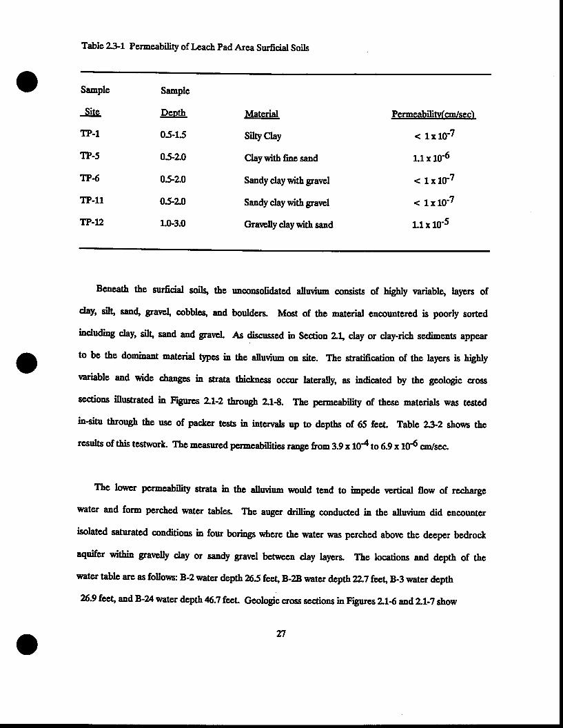
Table 231 Permeability of Leach pad Area Surficial Soils
Sanple
Site
TP-1
TP.5
TP6
TP.l1
TP-U2
Sample
Deoth
05-15
05-20
052.0
05-e0
1.0-3.0
Material
Silty Ctay
Ctaywith fine sand
Sandy claywith gravel
Saady day with grarrel
Gravelly claywith sand
Permeabiliw(.cn/sec)
< 1r10-7
1.1x 10⁶
< 1x10⁻⁷
< 1x10⁻⁷
1.1x 10⁻⁵
Beneath the surficial soils, the rmconsolidated altwium consisc of highly variable, layen of
clay' silq san4 gavel, cobbles, aad boulders. Most of thc -aterial cncountered is poorly sorted
including clay' silg sand and gravel As discussed in Section 2.1. clay or clay-rich sediments appear
to be the dominant material types in the alluvium on site. The stratification of the layers is higbly
variable and wide changes in strata thic.kne.ss occur laterally, as indicated by the geologic cross
sectious illustrated in Figures 21-2 througb 2"1€. The permeability of these materials was tested
in-situ through the use of packer tests in interrals up to dcpths of 65 fecL Terblrc 232 shou6 thc
results of this tcstwork. The mcasured permeabilities range from 3.9 x 10⁴ to 6.9 x 10⁶ on/see
The lon'c'r pcrncability strata in the alluvium would tcnd to irnpede vertical flow of rechargc
watcr and form perched water tables. The auger drilling conducted in the alluvium did encounter
isolatcd satruated conditions in four borings where the water was perc,hed above the deeper bedrock
aquifcr within grarrelly clay or sandy gravel between clay layers. The locatiors and depth of the
water table are as follovn: B-2 water depth 265 fee! B-28 water depth 2,.7 feo\B-3 water depth
%.9 fee\ andB'24 water depth 6.7 fceL Geologic cross sections in ngures ?^!-6 and21-? show
n
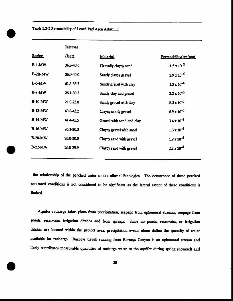
Table2}2Permeability of Lcach Pad Area Allwium
Borins
B-l-lvfw
B-28-lvfW
B-s-lvfW
B€.MW
B-10-tvIW
B-lllvf\il
B-l|.lvfw
B-16lvfw
B-Z)-lvflil
B-22-lvf\il
Interval
(feet)
x3-40,.6
36.0-,CI.0
615653
26J-n2
2L.U25.0
&.8452
41.H55
26J-3/J,3
26.0-30.0
76.V29.9
Material
Gravelly clayey saad
Sandy clayeygravel
Sandygravelwith day
Sandy cJay and gravel
Sandygravelwith day
Claycy sandygrarrcl
Grarclwith sand and clay
Claycygravelwith sand
Clayey sand with gravel
Clapysand with gravel
Permeabilitv(cn/sec)
15 r 10-5
3.9x 10⁴
13x 104
32x 10-5
85x 10-5
6.9x 10⁶
3.4x 10⁴
13x 104
1.9 x 10⁴
22xt04
the relationship of the perched water to the allwial lithotogies. The occurrence of these perched
saturated conditions is not cousidcred ts be signific'nt as the latcral ctrent of these conditions is
limited
Aquifer recharge takes place fron precipitatio4 seepage from ephemeral strcamg seep4ge from
ponds, rescrvoirq irrigation ditches and from spring. Since no pordE rcservoirs, or irrigation
ditches are located within the project area, precipitation events alone defne the quantity of water
available for recharge. Barneys Creek ruDning from Barneys Canyon is an ephemeral stream and
likely coaributes measurable quantilies of recharge water to the aquifer during spring snoumelt and
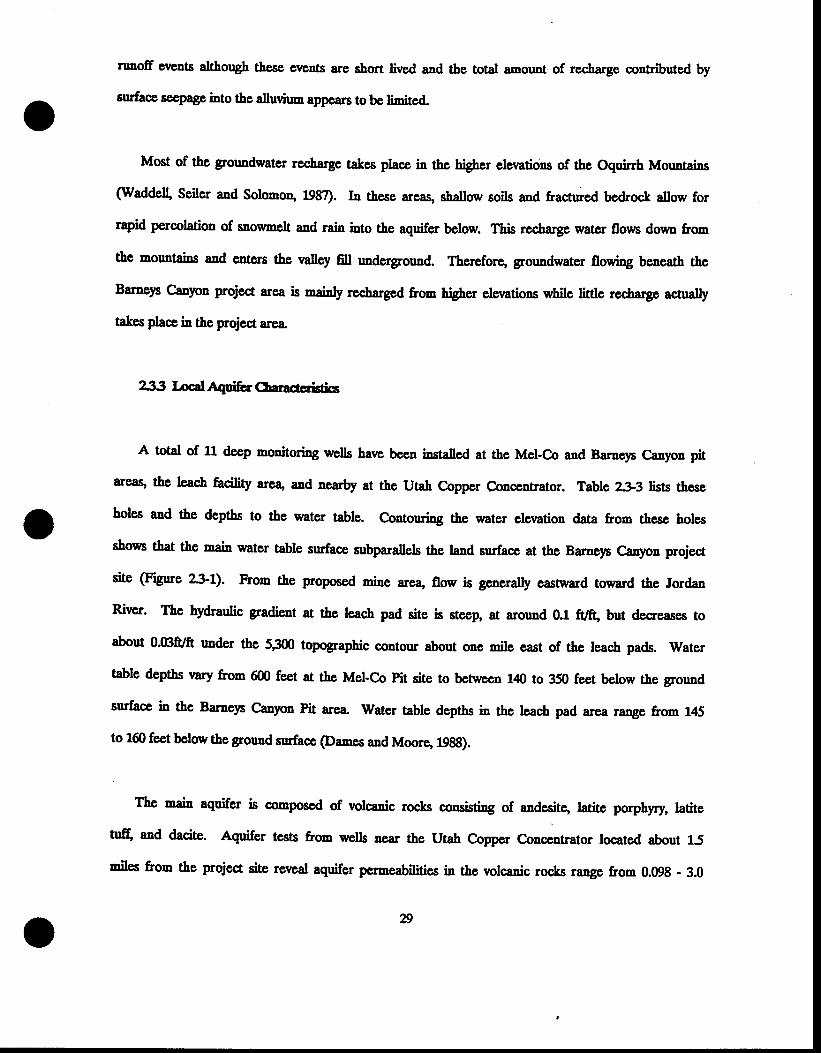
ntnoff Gvents atthough these events are short lived and the total anount of rccharge contributed by
surhce sccpage into the dlwiun appcars tobe linited-
Most of the groundwater rcclarge takes place in the higber ele\Etions of the Oquirrh Mountains
(Waddell' Seiler and Solomoo, 1987). Ia thcse areas, shallow soils and fractured bedrock allow for
rapid percolation of snownelt and rain into the aquifer below. ltis recharge water floun dovm from
the motmtains and entcrs the rnalley fill underground. Therefore, grormdwater flowing beneath the
Barneys Canyon project area is nainty recharged fr66 highsl elerations while little rec,harge actually
takes plae in the project area
233 LocalAquier Cbaractccigi,cs
A total of 11 decp monitoring welts harre been installed at the Mel-Co and Barneys Canyon pit
areag the leach facility area, and nearby at the Utah Copper Concentrator. Table 233 lists these
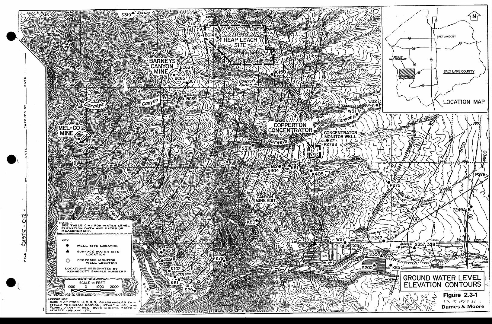
holes and the depths to the water table. Contoruing the water clevation data from these holes
shows that the rnain watcr table surface subparallels the land suface at the Barncys Canlon projecr
site @grue z3it). From the proposed mine arean flow is generally eastc/ard toward the Jordan
River. The hydraulic gradient at the leac,h pad site is steep, at around 0.1 ft7ft, but decreases to
about O.Bff/ft under the 53ffi topographic coutour about one mile cast of the leach pads. Water
table deptbs vary from 600 feet at the Mel-Co Pit site to betwcen 140 to 350 feet below the ground
surface in the Barnqn Canyon Pit area. Watcr table deptbs in tbe leach pad area rangp from 145
to 160 feet below the ground surface (Damcs and Moorg 19gg).
Tbe main aquifer is composed of volcanic rocks consisting of andesitg latite porphyry, latite
tu$ and dacite. Aquifer tests fron wells near the Utah Copper Conceutrator tocated about 15
miles from the project site reveal aquifer permeabitities in the volcanic rocls range from 0.098 - 3.0
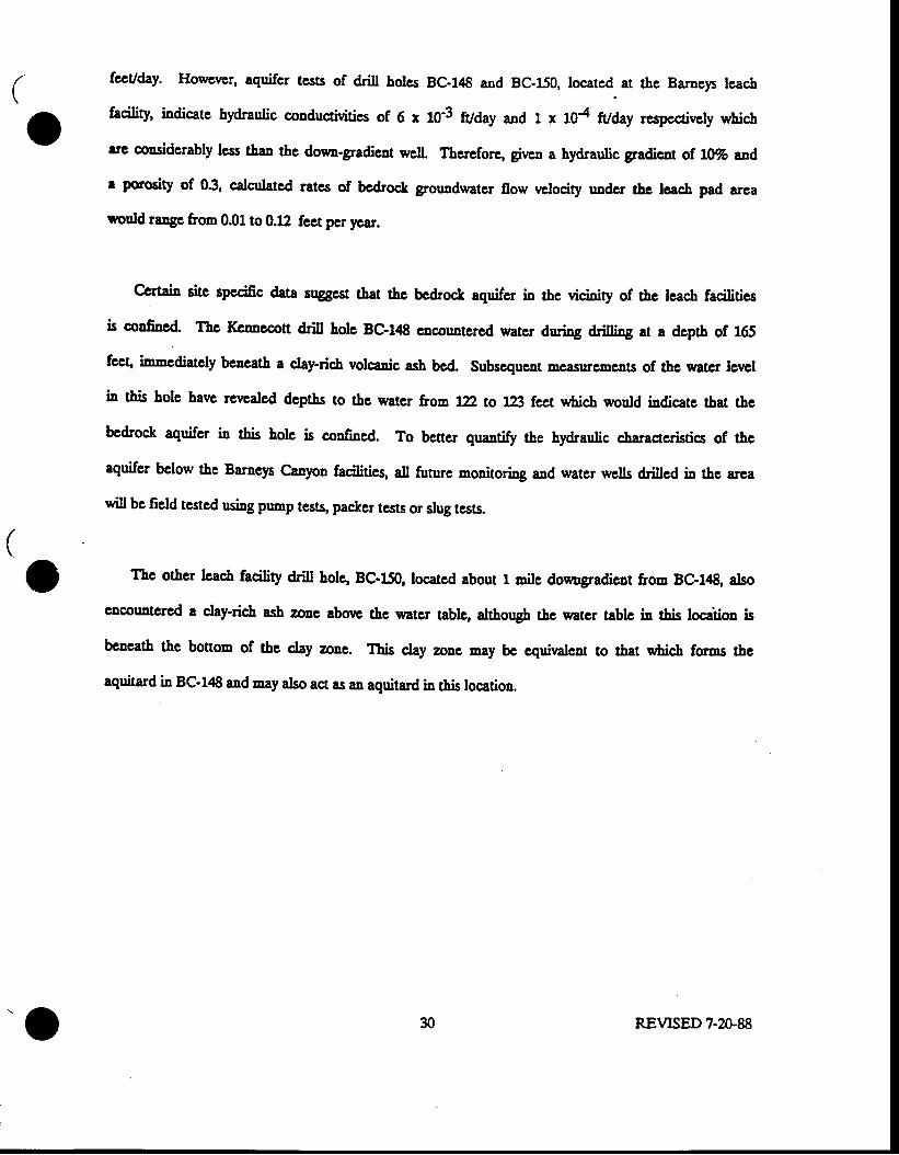
feUday. Howener, aquifcr tesg of drill holcs BC-14 and BC-150, locatcd. at the Barnep lcacb
facility, indicate hydraulic conductivitics of 6 x m'3 fl/day and 1 x 104 ft/day rcspcaively uAich
arc considcrably lcss rhrn 1f,s dowu-gradicnt well. Thercfore, givcn a hydraulic gradicot of,lT% and
e porosity of 03, calculatcd ratcs of bc&oce grouadwater 0ow rdocity undcr tbc lcacb pad arca
*onld range &om 0.01 to 0.12 feet per '€,ar.
certaiD site spccific data suggcst tbat thc bedrock aquifer in thc vicinity of thc lcacb facilities
is confiacd. Tbc Kcnnecon drill hole BC-!|8 enooultcrcd watcr druing driltirg ar a dcptb of 165
fceg immediatcly bcacath a c;lay-rich volcaaic ash bcd. Subsequent EeasurcEents of thc cater lewl
iD this hole havc rcwaled dcpths to ths water froE lD, to lB flx:t u&ich would indicatc tbat thc
bcdrock aquifcr i! this bolc is confincd. To bencr quartr$ the hydraulic charaacristics of tbe
aquifer bclow the Baraeys Canyon facilities, all future mouitoring and watcr wells drillcd in thc arca
will bc ficld tcstcd n<ing pnrnp tesq packcr tests or slug tests.
The othcr lcach facility drill hole, BC-150, locatcd about 1 mile dowogradieut froo BC-148, also
cncouatcred a clay*ich ash zoae aborc thc watcr tablc, althougb tbc water tablc ia rhic tosiliss ig
beneath thc bottom of thc clay zoue. This clay zone Eay bc cquiralcnt to that c,ticl forEs the
aquitard i! Bc-l/E and may also act as an aquitard ir' this location.
REVTSED 7-20-8830
llF
o
ooLlxuld
u
ltF
o
NOTE -SEE TABLE C. I FOR W.ATER LEVELELEVATION G,ATA AND DATES OFM E A S U R E M E N T .
'/r.0//z(esv\=:1\\\ut\\\-//,__\\\\\))\\\\SCALE IN FEET
rooo o rooo 2o9o NNN\-/.tttt,
'//za?)lltlltt,l,tK\\\\\5tllltru(KA,R€FERENCE
A A ' S E M A P F R O M U . S . G . 5 . Q U A O R A ' N G L S S E N -T I T U D n B t N G H A M C A ' | , r y O N , U T A H n - 1 9 5 2 . ^ N OtL .ARK" UT^Hn - t952. go lx g reeTs f ,HoTo -RE\ / ISED t969 A.NO r975.
GROUND WATER LEVELELEVATION CONTOURS
Figure 2.3-15 1 \ r w L i l I
Dames & MooreS-
ol
\N*
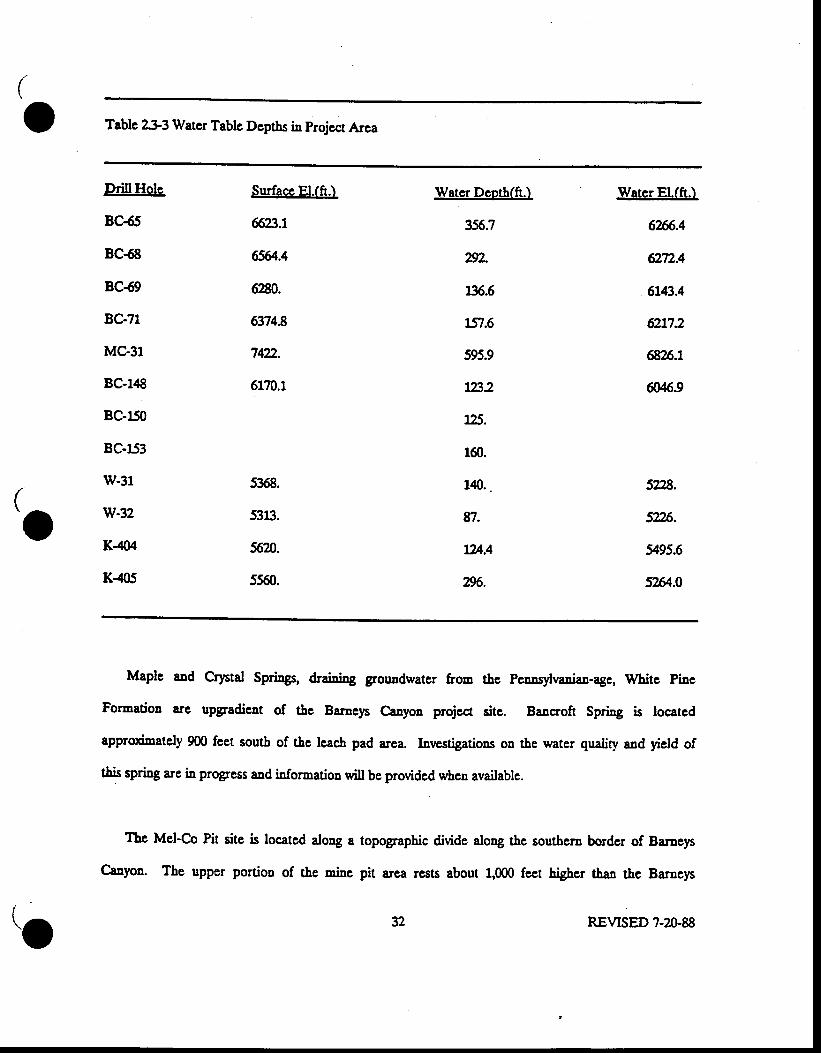
Table 2$3 Watcr Tabtc Dcptbs in projcct Area
DrillHole
BC{5
BC{8
BC69
BC-?1
MC€r
BC-148
BC-150
BC-153
w-31
w-32
K-404
K-405
Surface El.(ft.)
66,23.t
6564.4
6?N.
63748
742-
6170.1
5368.
$a.
fi20.
5560.
Water Deoth(ft.)
356.7
2v2.
136,.6
751.6
595.9
r23.2
125.
1@.
140..
&7.
724.4
2:!96.
Warer El.(ft.)
6?6.4
6Tn.4
6143.4
6217.2
6826.7
M.9
5228.
5n6.
1495.6
52&.0
Maple and Cqrtal Springs, d3aining grouadwater from tbe Pcunsylraniaa-age, Whitc Pine
Formation are upgradient of the Baruep Canyoa projea sitc. Bancroft Spti"g is locatcd
approximately 900 feet soutb of the lcach pad area. Investigations ou the water qualiry and yield of
tbis spnng are in progress and information will be providcd when available.
Thc Mel'Co Pit site is located along a topographic divide along &e southera border of Baraeys
C;anyon. The upper portion of the rnins pi1 area rcsts about 1,000 fect higber thqn 1f,s Barnep
II
\ ^-.
v32 REVISED 7-20-8
Canyon Pit sitc. Thc Potcntiometric surfacc bcnca& thc ridge lies at a dcpth of approximately 600
fcct bclow thc surfacc. Thc aquifcr is madc up of Kirkman, Cfinfer and Curry Formatious wLich
typically have perocabilitics tbat are quitc low. Sincc no aquifer tcsts haw bcco done at this site,
pcrmeabilitics 31'g gstimalcd to be the sanc 8s the aquifer bcneatb Barneys projca sitc. Assuming a
hydraulic gradicnt of l}.Vo and a porosity of 30Vo, grouudwatcr f,ow rrclocitics would aot significantly
dificr from tbose calculated at the Barncp Canyon project arca.@anes and Moore, 1988)
L3.4 Bascli"c Grouadratcr Ouality
Rcccut c,baractcrization of the grouadwatcr quality from wclls and springs uear thc Baracp
Canyon Projcct area bas beea performed. Sincc few activities harr occurrcd nortb of Bingbam
Canyon along the basc of tbe Oquirrb ldsusrainc, grouadwater qualiry has likety remaincd unaffectcd
by man's activities.
Water quality aaalpcs performcd on thc wclls at thc aew Utab C,opper Conccntrator (W-31 and
w'32-A), thrcc monitoring welts located 1 to 3 miles dormgradieat of the projcct site (p-225, p-n6,
and P'2788) and Barncp Spring (5'318), indicate that groundwatcr qualiry dow4gradicnt is gcocrally
good with tbe cxceptios sf high conccntrations of citoridcs (200 - 500 nfi) Eod high 161at
di"sohrcd solids CIDSXT()39 - 1650 ng[) (appeadix B). Valucs grcatcr thaa 500 mg/l cxcced
sccondary &isJHDg water stasd&rds. Water quality analpes from samplcs tateu from aouitoriag
wclls BC ' 1tl8 aad BC ' 150 west 8.ud south of tbe lcach pad arca iadicatc grouodwatcr quality is
good. TDS ralues rangc from 825 to 9U rrgl. Ficld elccrrical conductivity mcasucmenrs ir thcse
wclls werc 1100 and tStQ *rnhss (see Appendix B). Watcr qnality analpes wcrc conductcd on
samplcs for Bancroft Spring, locatcd soutb of thc proposcd lcacb pads. Watcr quality in rhis spring
sc0c{ls many of the samc gcneral chemical conccntrations as was fonnd in the otbcr spring and
c/clls. Thc results of thi< anatysis may be found in Appendix B.
REVISED 7-20-8f,
Baseline grouadwater quality paranctcrs have aot bcco cxamined at tbe Mcl-Co Pit sitc. The
Deatcst locatioos from which water quality data has bccu inrrcstigatcd is L3 rnilcs d6**"dient of
thc pit in the Dry Fork Crccl &ainage basin (Figurc 23.1), sourheast of the Mel-Co pit site.
I! 196, conccatratioa lewls of fDS (1,300 - 46500 mgll), sulfatc (8,600 - 17,8m mg/l), coppcr (6-
lU Egn), c,bloride (1,g00 ' ?:1n rugn) and vcry tow pH ralucs near 3.0 wcrc cnoountcrcd @amcs
aad Moore, 198s). A complete listiDg of tbese ralucs oaybe fouad in Appendix B.
?.4 Soils
?-4.1 Tcctsical epproach
A soil sun'ey was conducted in October-Novcmbcr, 198? at tbe Baroeys Caayou projcct site.
The SCS Soil Sun'ev of Salt Lalc Area. Utah was ucd as &c basis for tbc gronad suwey. Pits or
&esh road cuts wcrc rscd to obtain proElc descriptions and dc6ne thc actual soit boundaries on the
projcct sitc. Soil sanples c,crc obtaincd aad sent to a conncrcial laboratory for fcrtitity aaalyses.
v REVTSED 7-U-88
The averagc surface lapr and subsurface layer thicknesses were used to define potential naxinun
topsoil depths.
242 Soilrypcs
lto soils on the east slope of the Oquinh Ratge are derived from mixcd sedimcntary rocks or
the allwium and colluvium from mircd sedimentary roc,ks. The soils of the projcct area all lie above
the 5100 foot cleration an4 thnq 8re not influenced by the prehistoric Lake Bonncville. The soils
are calcareous througbout with additional but variable, Iime acanmulation in the C horizons. The B
horizons arewell developed in the deeper soils of the lower slopes.
Plate IV presents the soil nap for the prqject area Five soil associations occur within the
projcct area" The Agassiz-Bradshaw Association is found on steep slopes in the Mel-Co pit area.
Thc Fiegcrald soils arc found on the north-facing slopes with ft forests. The Gappmayer-Wallsburg
Association is found on ridges along the Mel-Co haul road. The Harker soils arc found in the
Barncys Canyon pit and dump areas. The Dry Crcek-Copperton Association is found on the lowcr
slopcs where the leach pads will be sited.
The frrll profile descriptions for tbe soil associations can be found in Appendix C-tr. Detailed
descriptions of each soil association are presented below.
Bradshaw-Agassiz Association
Asassiz
The Agassiz soils occur on the steep ridges around the Melco pit and dump. They are
35
sballow (<20 inches), well-drained soils over bedrock Thc surface layer is very cobbly silt
loam' and the subsurface layer is also rrcry cobbly silt loam that is slightly calcareou. The
average topsoil depth is 12 inches but numerou rock outcrops wilt linit thc actual anount
salwged The SCS describes the potential for erosion gs high.
Bradshaw
The Bradshaw soils occur in association with Agassiz soils in thc Mcl-Co pit and dump area but
are usually found in concaw positions of the slopes over colluvium- the surface layer is very
cobbly silt loam as is the ligbter colored subsurface lalcr. The horizons are weakly dcrreloped.
The substratum is collwium developed from limqstone and quartzite. The average topsoil depth is
20 inche.s but some sites will contain topsoil to fl) inches or more. The potential for erosion is
higb, accordingto the SCS.
Fitzserald
ltis soil is found on the nortl border of the Mel-Co pit on the north slope of the ridge.
The vegetation is a spruce-fir forest with limited understory. Ite surface layers are dark
grayish-brovm gravelly loam and the subsurface layers are yellowish-brown gravelly silt
loam- The substratum is colluvium ald rcsiduum from mixed sedimentary rocla. The topsoil
depth averages 18 inches. The scS lists the potential for erosion 6s high for this soil t1pe.
36
Gaopmaver-Wallsbure Association
Gaoomaver
The Gappmayer soils are located on north-fac-irg slopes along the Mel-Co to Barneys haul road
route. The parent material is colluvium and residuum from mixed sedimentary rocts. The
surface layer is rrery cobbly loam and gaveUy silt loan and the subsurface layers are rrcry
gravelly silt loam- Tte depth of topsoil is Z inches. The SCS states that the potential for
erosion is moderate.
Walsbure
This soil occurs with the Gappmayer soits uually occupying the ridge tops and upper parts of
the stccp slopes. The parent natedal is cotlwium and rcsiduun from mixed sedimentary roctrs.
The surface lalcrs are very cobbly loam while the subsurface layers are very cobbly silty loam.
Bedrock is present at 1? inches. lte deptb of topsoil is about 15 inches. The potential for
erosion is described as high by the SCS.
Drv Creek-Coooerton Association
Coooerton
The Copperton soils are fouod in association with the Dry Creck and Harkcr soils and occur on
nalro\il ridges and drainagcs that traverse the loqg allwial fans. The soils formed over alluvium
derived from mixed sedimentary roclc The surface layers are very gravelly and very cobbly
loan and the subsurfacc layers are rrcry cobbly fiae sandy loam characterized by lime
n
accumulations. The topsoil depth arrcrages 18 inches. The potential of erosion is moderate,
according to the SCS.
Drv Cteek
These soils are on the easterly slopes of high alluvial fans- in the Barney Canyon pit and dump
area aad in the leach pad sites. The surface layers are silt loam and the subsurface layers silty
clay loan to silty clay. A distinct lime accumulation oocurs bclow the subsurface la,,ers. The
topsoil deptb can be up to 40 inc,hes. The SCS reports that tbe erosion potential is modcrate.
Harker-Drv Geck Association
Harker
The Harkcr soils are in association with the Dry Creck and Copperton soils in the Barneys
Canyon pit and dump area and occur on the higher elevations of the fans and drainages. The
surface layers are heary loan rvtile the subsurface lalcrs are gave[y clay loam to gravelly
clay. Tte substratum is vety gravclly clay loam- fhe topsoil dcpth arcrages 40 inches. The
for erosion is described as moderate by the SCS.
Outcroos and Talus Slooes
these arsas on ridge-tops and on stecp sropcs are gcnerally devoid ofsoils.
38
RoclrvVariant
this soil oocurs on the south slope of the Baraep pit site. It is a very sballow soil of
about 6 inches over rock unli&e the surrormding Harler soils. It would not be suitable for
u,se as topsoil because of the e,xtreme roc,kiness.
Z43TopsoilOuafty
All the soil materials are very gravelly and/or cobbly and are, therefore, dominated by coarse
particlcs. The soil tcxturcs range from tsarns [s silt or clay loams to silty cla]6. The organic
mattcr is utully above LA% x'hich is higber tbal that normatly found in f,esin asd Range soils.
Sufficient plant macronutrients of nitrateg calciuq potassium aad magnesium are present for plant
grouth- Phosphonrs is deficient as is rsually thc case in Basin and Range soils. This wi[ require
fertilization to correct the deficiency.
Laboratory reports for soil ferdtity and chenistry are prescnted in Appendix c-tr.
The eoil quality for each of tbe principal soil qpcs identified in the soil survey are described
below:
Bradshaw-Aeassiz Soils
Thqse cobbly silt loams are slightly acidic with a high percentage of organic matter in the
surface and subsoil horizons. The cation exchange capacity is moderate. The phosphates levets
are low as e,:rpected"
39
Fitzeerald Soil
This acidic soil is cobbly and coarse. It has a moderate to low potential for nutrients. The
organic mattcr level is moderate. fhese soils will probably be only sllghtty disnrbed by the
rrining operation"
Gaoomaver-Wallsbrug Soils
These soils are neutral and noderately fertile. The organic matter is about LSVo.T\e phosphates
are low. Some highcr-than-normal copper and sulfate levels are found in the surface horizons.
C.oooerton Soils
The relatively shallon, Copperton soits are sligbtly acidic with moderatc fertility. Ttere is a
moderatc amount of organic matter is the topsoil materials. The coppcr contcnt is relatively
high ia the surface layer.
Harker-Drv Creck Soils
These soils are generally decper than othcr soils of the arca and will provide the bulk of the
topsoil material This is cspecially truc for the Harker soils rvtie;h are the deepest soils and
occllpy much of the distubed areas of the Barney Pit and dumps. The soil tetrure raries from
loan to clay loam with clan in the lovrcr B horizons.
The soils are aeutral to slightly nllralino with moderate fertility. The perceat of organic matter
varies but is gcnerally lower tban the other soils in the area. Phosphates arc low 8s cryected-
,10
one incident of high copper levers in the sruface horizons was formd.
25 Vqrtatim
The Barnep Canyon area of the oquirrh Mountains ranges from an clevation ot g242 fcet at
Baraep Pcat to 5,100 fcct at state Highway 111 on the cast slopcs. Gcncrally all of the major
plant commuaities are nariants of thc oa&doninatcd mountain shrub plant The ganbel
oak (OuercuS. sambeliil occurs gs :rnnlt shrubs on the higher c4osed ridgpE as tall shrubs on srnnll
trccs on the protcctcd upp€r stopcg as medium shrubs at mid-slopcs, and as *nrlt shrugs in
scatterpd cl.mps on the rourcr alwiar, sagsbrush-dminatcd slopes.
The steep tcmain cmphasizes thc difrcrcnce in aorth and south aspects. Conifen and heavy
stands of sbnrbe charactcrize north aspects rvtile south and west aspects support pure oak stands
and curleaf nahogany (Ccrcocamus tedifolius) stalds on the rocky soils and outcrops. Sagebnrsh(Artemisia tridentata) atso edsts at all elerations aad in most of the plant commrmities but bccones
doninant only on the lower alluvial slopas and ridgc tops.
A vegetation conmunity map was dcvcloped for all thc arca affectcd by thc o|I,erall mining
project' This map is prcseotcd on Figurc 25-1. The arca was surrrcyed on thc gropnd and
comumity boundarics drawn onto topqgraphic naps. one hundred-foot, line-point transects werc
run in cach major plant conmrmity on the sites of proposcd mining activity.
The rregetatira napping arbitrarily established boundaries for the rlarious oak sbrub communitics
as dcscribed aborrc' In reality thcse communitics do aot harrc dcfinite boundaries but grade from
me community to the ner. Thug many connunity bormdaries or e,rtremities are charactcrizcd by
ccotoDes' AIso many subcomnunities or cscnsions of a-djaceat commrmities can exist within the
4l
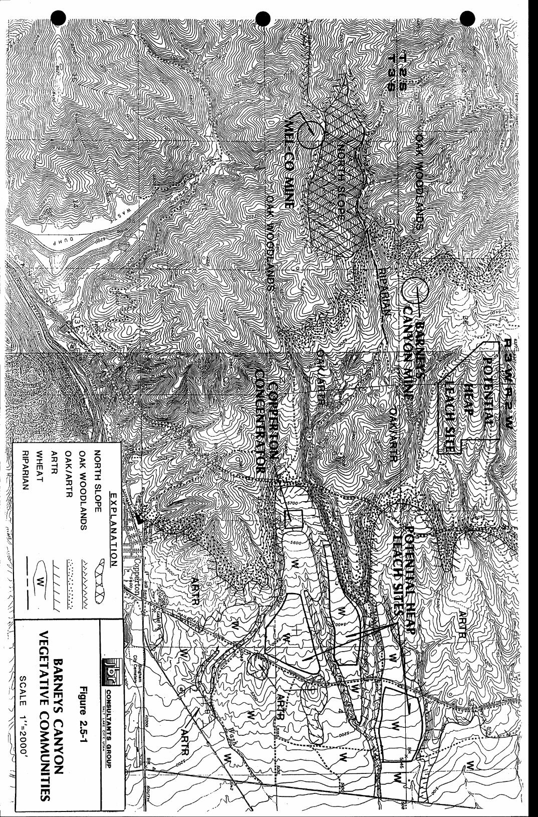
k-///,vi
major com'nunities rsually due to terrain aberrations.
25J Oat Woodlaads/hfiourtain Brosh Cmmty
This plant ranges in eleratiou from 6800 feet to 8200 feet. It is characterized by
oak woodlands composcd of rrnnll trees on favorable sites but can be oak shrub stands on less
favorablc sitos. The opcn arcas bstwscn shnrb and trcc stands are rrcgetatcd with grasscs and smrll
sbnfts. ltc north slopc vcgctatiou can cxist within the general arca 8s snall stands in pockets or
as commrmities covering large steep aorth slopc ueas. grnnll stands of aspcns (beulus tremuloides)
occrr in thc dccper soils of stccp drainagcs or qfictp thc melting of snow ba*s keeps the soil
noist. Therockykuollsofshallonreoilareasmaybavestandsoforleafmabogany.
This comormityoovett dl the Mel-Co pit and dump site areas.
The rrcgetatirc corrr for this plant communityis summarized as folloq6:
Groud Correr, percent:
Bare soil 14, me,as 2.7
Rock $.6, mean 3.0
Litter $-48. mean 28.2
TotalNon-vegetatiw D49,me.an?43
Vegetative 51-?& mean65.?
Overstory 6[ mean3g3
Vegetatirc Cover, species ranked byperceat:
Ouercus sambeti
Aproowon soicatum
B alsamorhiza sacittata
(Gambel oak)
(blue-bunch wheaSrass)
@alsanroot)
43
20.0r
153
13J
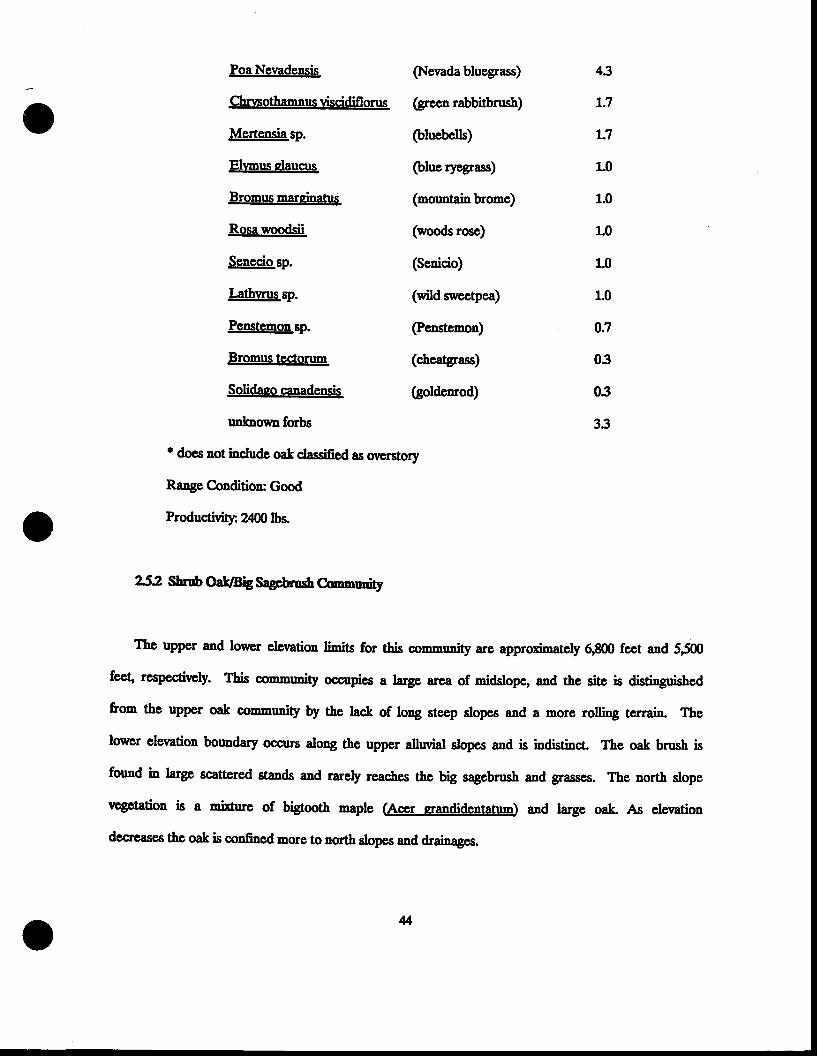
oPoa Nevadensis
Chrvsothamnus viscidifl onrs
Mertensia sp.
Elrmus daucts
Bromus marcinatus
Rosa woodsii
Senecio sp.
Lathvnrs sp.
Penstemon ep.
Bromus tcctorum
Solidaso canadensis
rrnlcnowa forbs
(Nevada bluegrass)
(greco rabbitbrush)
(bluebells)
(blue ryegrass)
(mountainbrome)
(woods rose)
(Scnicio)
(wild sntectpea)
@enstcmon)
(goldenrod)
43
L:7
L7
LO
1.0
1.0
1.0
1.0
0:l
03
03
33
' docs not include sa! classified as oveEstory
Range Condition: Good
Productivitlr 24m lbs.
252 Shn$ Oa&tsig Sagrnmsh C@nudty
The uppcr and lourcr elevatioa limie for this coumunity are approximately 8800 feet and 5500
feet respectinely. This conmrmity occupies a large arca of midslope, and the site is distinguishcd
from the uPper oak commuaity by the lac.k of long steep slopes and a more rolling terrain. The
lower elevation bormdary oocurs along &e uppcr allwial slopes and is indisthct. The oak brush is
formd in large scattered stands and rarely reaches the brg sagebnrsb and grasses. The nortl slope
vtgctation is a mixture of bigtooth maple (Accr crandidentatum) and large oak" As elevation
dccreases the oak is confiaed Eoro to north slopcs and drainages.
4
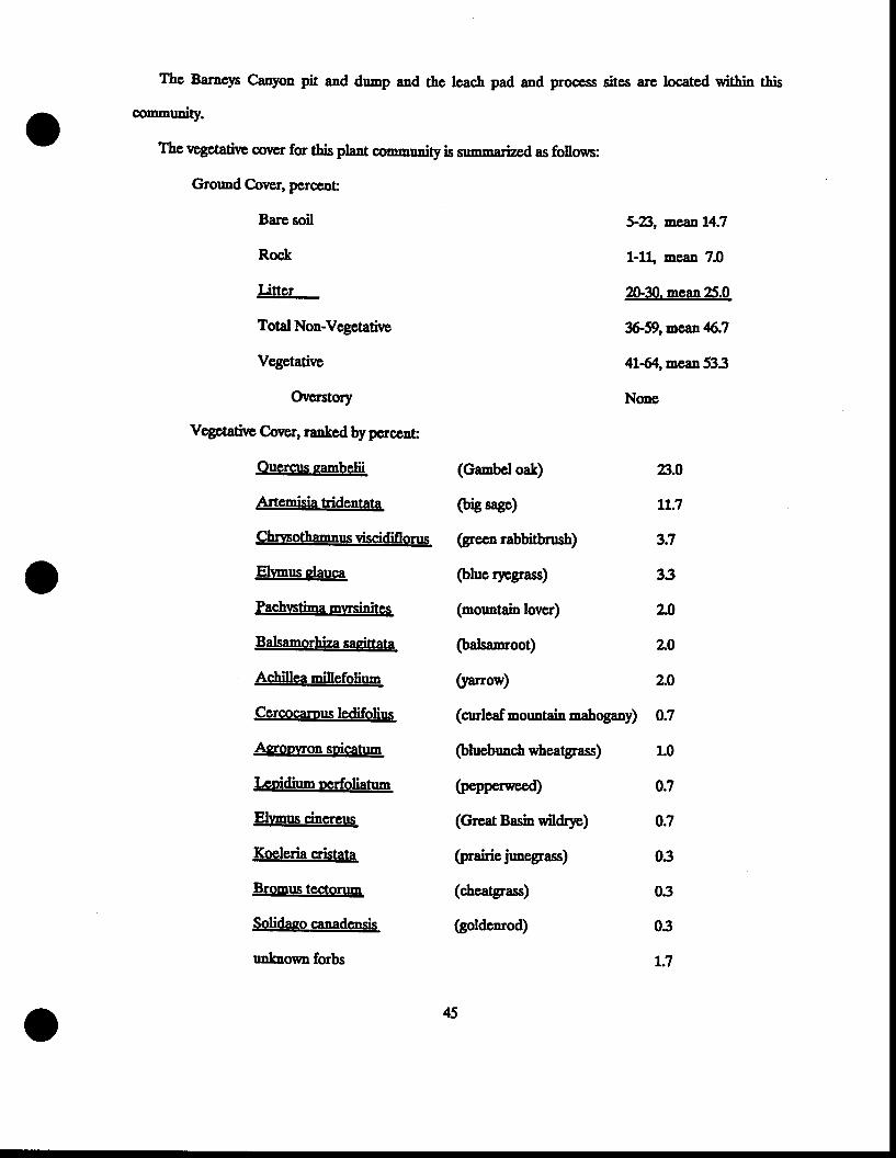
The Barncp C;anyon pit and dunp and the leach pad and proccss sites arc located within this
comnuity.
The rrcgetativc covcr for this plaot conmrmity is snnnarizod as fo[ou6:
Groud Cor€r, pcrceng
Bare soil
Rock
Litter
Total Non-Vegetatirrc
Vegetative
Overstory
Vegctatiw Cover, ranked by pcrcent:
Ouercrs eambelii
Artcmisia tridentata
Chnnsothamaus viscidiflonrs
Elvmus dauca
Pachvstina mwsinites
Balsanorhiza sagittata
Ac,hillea millefolium
Cercocamus ledifolius
Asroovron soicatum
Lcoidium oerfoliatum
Elvmu cinereus
Koeleria cristata
Bromus tectorum
Solidaqo canadensis
unknoum forbs
(Ganbel oat)
(brg sagc)
(gecn rabbitbrush)
(blue $cgrass) 33
(mountain lover) 23
(balsanroot) L0
@rros') L0
(orlcaf mormtain nahogany) 0J
(bluebune,h wheatgrass) 1.0
(pepperweed) 03
(Great Basin wildrye) 0:7
(prairie jrmegrass) 03
(cheatgrass) 03
(goldenrod) 03
LJ
45
5-8, aeant4.7
1-1t mcan 7.0
2&30. mean 25.0
*59,meat46J
4L-64.,mean533
None
8.0
LL:I
3J
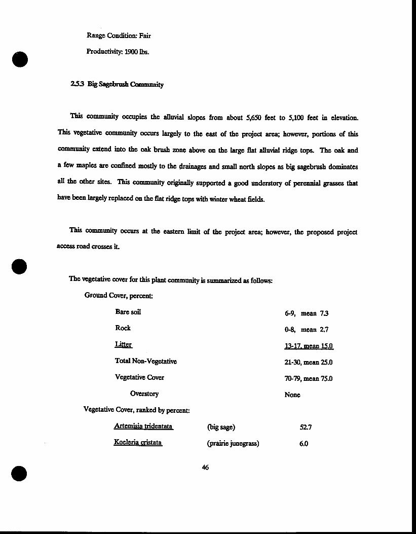
Range Condition: Fair
Productivity 19mb6.
53 Big Sagcbrush Cb''-nin''rly
This connrmity occupics the alluvial slopes from about 5,650 feet to 5,1fl) feet in eleration
Ttis vcgetative oommrmity occuts latgely to tbe cast of thc project area; horercr, portions of this
community erCend into the oak bnrsh zonc aborr on the large flat alluvial ridgc tops. The oak and
a few maples are confined mostly to thc drainages and snall north slopcs 8s big sagebnrsh dominatcs
all thc other sites. ltis comnrmity originaly supported a good of percnnial grasses that
hare bccn largely replaced on the flat ridgp tops with winter u&eat fields.
This conmunity occurs at the eastera linit of the project area; however, the proposed project
aooess road crosses iL
The rrcgetative cover for this plant conmrmityis summarized as folloc,s:
Grormd Cover, percent:
Bare soil 69, mcan 23
Rock 0-g, mean 2.?
Litter tl-12. mean t5.o
TotalNon-Vegetatirc 21-30, mean 25.0
Vegetative Correr 7F7g,mean ?5.0
Orrerstory None
Vegetative Cover, ranked by perceut:
Artemisia tridentata
Koeleria ETistata
(big sage)
(prairie junegrass)
s
5L7
6.0
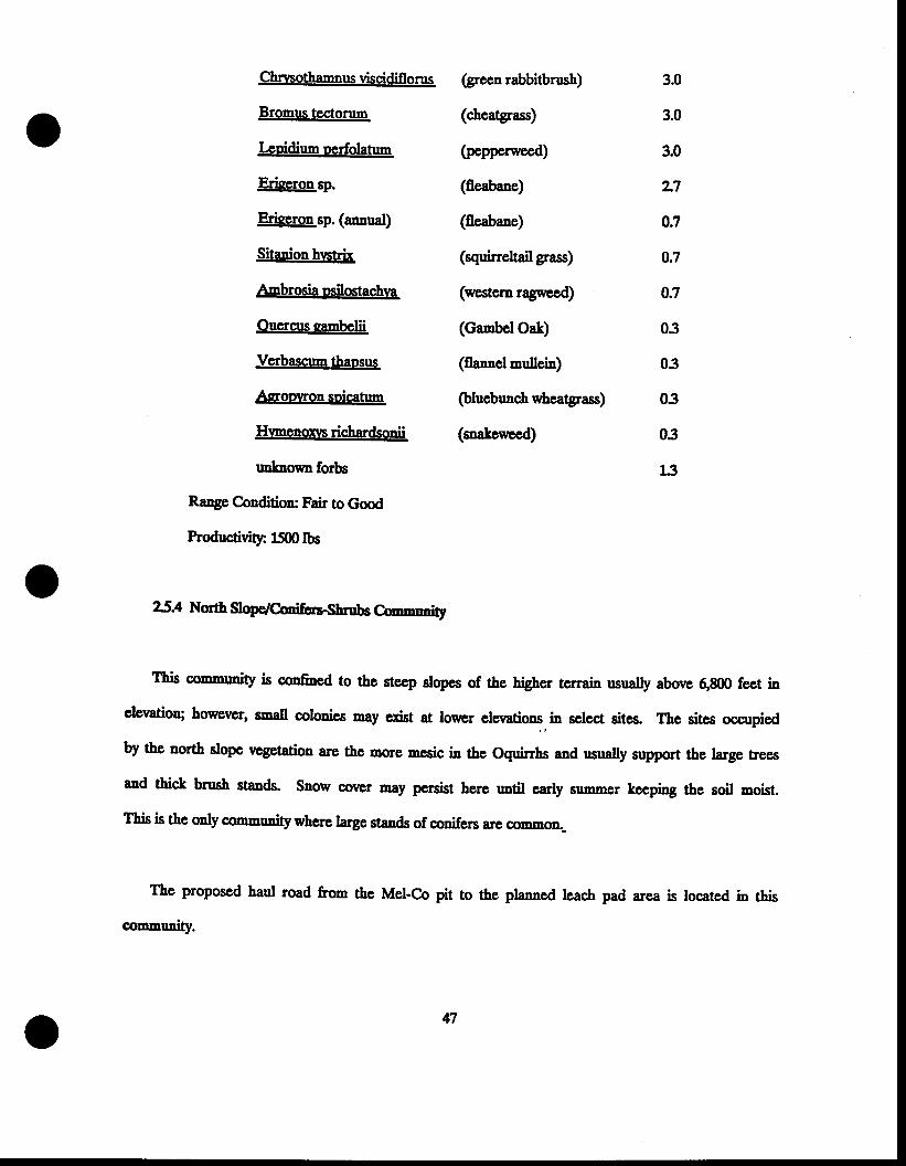
Chrsothamnus viscidif, onrs
Bromus tectorum
Lcoidium oerfolatum
Eriqeron sp.
Erieeron sp. (annual)
Sitanion hvsEh
Ambrosia osilostachva
Ouercrs eapbelii
Verbascum thaosrs
Asoovron soicatun
Hvmenoxn richardsonii
un&no*n forbs
Range Condition: Fair to Good
hoductivitlr 1500lbs
(gr.eeo rabbitbrush)
(cheagrass)
(pepperweed)
(fleabane)
(fleabane)
(squirreltail grass)
(western ragweed)
(canbel Oak)
(flannel mullein)
@luebunch
(snakevteed)
3.0
3.0
3.0
z7
OJ
OJ
OJ
03
03
03
03
L3
25.4 Nortt Soge/CoonhsSnrobs Car'rrnrmitt
This conmrmity is confilred to the steep slopas of the higher terrain rsually above 6,800 feet in
cleration; bowever, snatl coloaies may cxist at lowcr in select sites. The sites occupied
by thc north slope rcgetation are thc mone mesic iu the Oquinbs and rsually support the largc trees
and thick brush stands. Saon' oover may persist here rmtil carly sumner keeping the soil noist.
This is the only communitywhere large stands of conifers are oommo'-
The proposed haul road from the Mel-Co pit to the planned leach pad area is located iD this
n
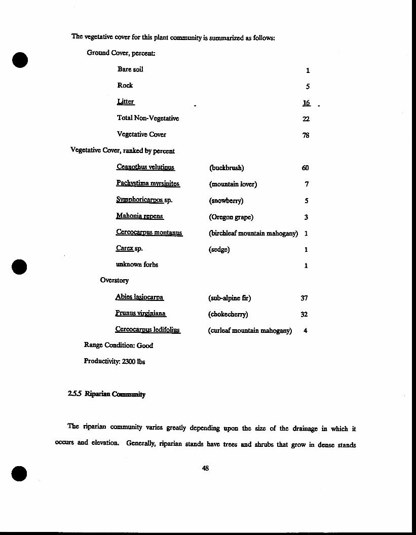
The vcgetative corrcr for this plant communityis summarized as follows:
Ground Correr, perccDt:
Bare soil
Rock
Litter
Total Non-Vegetative
Vegetative Corrcr
Vegetative Cover, rantcd by pcrceat
1
5
!6.
2,
78
Ceanothus \rclutiils
Pachrntina mvrsinites
Svmohoricamos qp.
Mahonia rcoens
Cercocarons montanus
Carex sp.
rnknoqm forbs
Ovcrstory
Abies lasiocama
Prunus virsiniana
Cercocamus ledifolius
RangeCondition: Good
Productivitlr 2300lbs
(buckbrush) 60
(mountain lovor) 7
(soovberry) 5
(Orcgon gape) 3
@irc.hleafmountainnahogary) 1
(sedge) 1
1
(subalpine fir)
(chokcclerry)
(arleaf mountain nahogany)
37
32
4
255 RiparianC@'''lrr'"t
The riparian comrnunity varies greatly dcpcnding upon the size of the drainage in which it
oosurs and elerration- Generally, riparian stands have trees and shrubs that grow in deuse stands
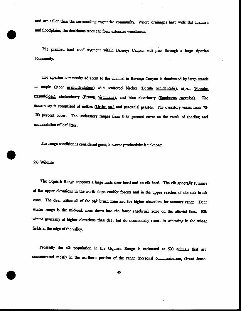
and are taller tha" the surrounding rrcgetatirc commrmity. Whcre drainages harrc wide flat c,hannels
atd floodplains, tbe deciduoru trces cqn form crensive woodlands.
The plaaned baul road segmeot within Barneys C;anyon will pass throryh a large riparian
community.
Thc riparian comnuity adjaceat to the chanel in Barneys Canpn is doninated by large stands
of maple (Acrlt sandidentatum) with scattered birches (@lt occidentalis), spon fpooulus
tre'muloides). chokecherry (Pnmrs drgipiana), and bluc clderberry (Sambucrs caerulca). The
undcrstory is conprised of nettles furtica g&I and pcrcnniat grassos. Thc overstory rmries from ?&
100 percent oovcr. Tte rmdcrstory rangcs &om G,35 pcrcant oovcr as the result of sbading and
acsrmulation of leaf litter.
Thc rango conditioa is considered good howe'er productivity.is'nknown
2.6 f,iitdtift
The oquirrh Range supports a large mule dccr herd and an elk herd. The elt generally sunmcr
at the upper clerations in the north slope conifer forcsts and in the upper reachcs of the oak bnrsh
zone' The deer utilize all of thc oak brush zone and the higher elernrtions for summer range. Deer
winter range is the mid'oat zone doum into the lower sagebnrsh zoDs on the alluvial fans. Elk
winter generally at higber elenations than deer but do occasionally resort to wintering ia the wheat
fields at the edge of the rralley.
Ptesently the elk population in the Oquirrh Range is estimated at 500 enimrlc that are
conceatrated nostly in the northern portion of the range (pcrsonal commrmication, Graat Jensg

oUtah Division of Wildlife Resources).
The deer density is about 0.17 deer per acre q 6 acres per deer. Othcr commoa rnernmrls is 1f,s
aroa are coyote.s,lagomorp\ badgerg skunes and the less common bobcat.
Raptors use the Oquirrh RaDge for aesting siteg summcr fe€ding areas on the upper slopes and
sintcr fecding areas along the lower slopes. Golden cagles nest in the cliffs on the crest of the
range. Cooper's hawks nest in the oak bnsh zone wcre small birds are plentiful and red-taited
hawks nest in 1f,s cliffs and large trces in thc canyong as does the great-horned owl Harriers are
common year-around in nct of thc habitats. A fall sureey following leaf fall did not rcveal any
raptor nests within the spccific proposcd disturbcd areas of thc project
Barnep Canyon and tributary streams support a riparian comnrmity of trees and shnrbs. Large
trees of maple and oak are used as nesting sites by many bird species and the sbrubs of
chokecherry, elderberry, serviceberry and others provide food for them.
50
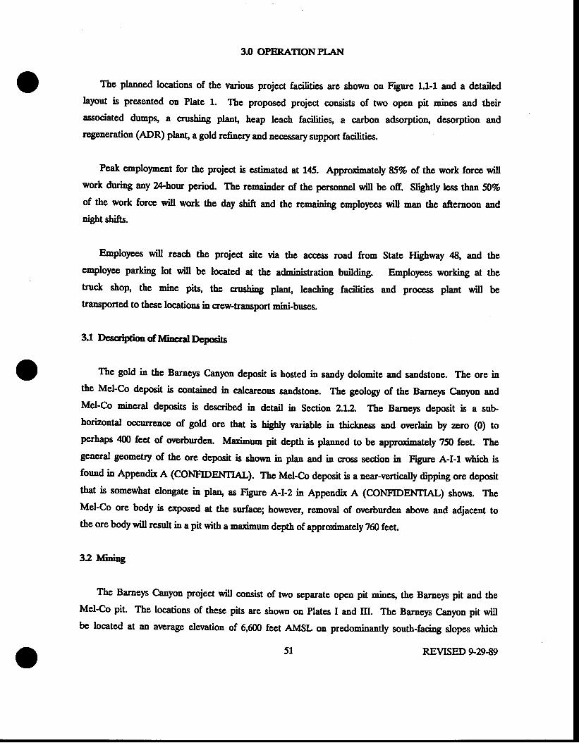
3I} OPERATIONPI.AI{
The planned locations of the rrarious project facilities are shown on Figure 1.1-1 and a detailed
layout is presented on Plate 1. The proposed project consists of nx,o open pit mines and their
associated d-pq a crushing plant, heap leach facilitieg a carbon adsorption, desorption and
regeneration (ADR) plant a gold refinery and necessary support facilities.
Peak cnplolmcnt for the project is cstimated at 145. ety 85Vo of the work fore will
work druing any Z-hour period. lte remainder of the penonnel will be off. Sligbtly lcss tha' 507o
of the work force will work the day shift and the remainiag employecs will -a. the afternoon and
nigbt shifrs.
Enployees will reach the project site via the access road from State Highway 48, and thecmployee parkiag lot will be located at the administration building. Enployees working at thetruck shop, $e mins pis, the cnshing plan! leaching facilities and process plant will betransported to these locations in crew-transpsrt minlguses.
3J Dcscripim of trfincml Dcpcits
The gold in the Barneys Canyon deposit is hosted in sandy dolomite and sandstone. The ore in
the Mel-Co deposit is contained in calcareou sandstone. The geologl of the Barnep Canyon andMel-Co mineral deposits is described in detail in Section 212. Tbe Baraeys deposit is a sub-horizontal oocurrenoe of gold ore that is highly variable in thickness and overlain by zso (0) toperhaps 4{D feet of owrburden. Maximum pit depth is planned to be approximately ?50 feet. Thegeneral geonetry of the ore deposit is shown io plao and in cross section in Figrre A-I-1 which isfound in Appendix A (CONFIDEI{"flAL). The Mel-Co deposit is a near-r,ertically dipping ore depositthat is somewhat elongate io plaq as Figure A-I-2 in Appendix A (CONFIDENTIAL) shoun. TheMel-Co ore body is e':rposed at the surface; however, removal of owrburden above and adjacent tothe ore body will result in a pit with a maximnm depth of approximately 760 feet.
32 Mning
The Bar:reys Canyon project will consist of nvo separate open pit nines, the Barneys pit and theMel-Co pit. The locations of these pits are shoum on Plates I and III. The Barneys C.anyon pit willbe located at an averqge elevation of 6,600 feet AIr{SL on predominantly sou&-faciag slopes which
51 REVISED 9-29-89
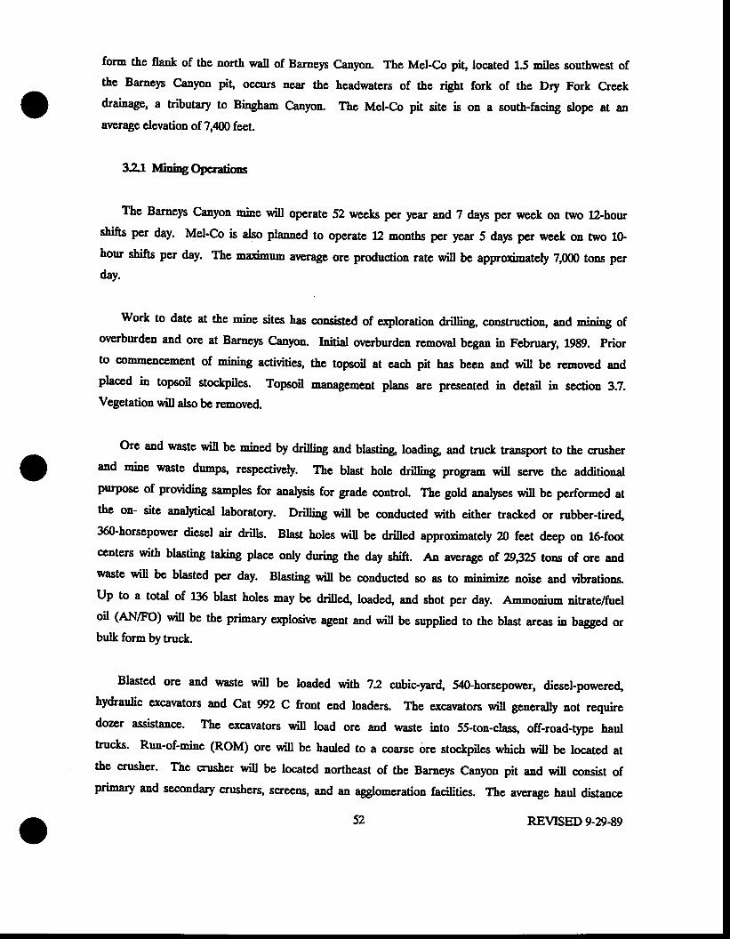
form the flent< of the north wall of Barnep Canyon- The Mel-Co pit, located 15 miles southwest ofthe Barneys Canyon pit, occurs near the headwaters of &c right fork of the Dry Fork Creek1ft'ainege, a tributary ts f,inghap Canyon. ThE Mel-Co pit site is on a south-facing slope at an
average elevation of 7,{69 ;"",.
321 Irrfiningapcmtims
The Barncp C;anyon rnins will operate 52 weeks per year and ? dap per week on two 12-hourshifts per day. Mel-Co is also planned to operate 12 montbs per ),ear 5 days per urcek oa two lGhour shifts per day. The madmum average ore production rate will be approximately 7,000 tons pcrday.
Work to date at the mine sites has consistcd of oploration drilling, construction, 6ad mining oforarburden and ore at Barneys Canyon. rnitial overburden removal began in February, 1989. Priorto commencement of mining activities, thc topeoil at each pit has been and will be removed andplaced in topsoil stoclpiles. Topsoil rn'nagenent plans are presented in detail in section 3.2.Vegetation will also be removed.
Ore and waste will !s rnined by dri[ing and btasting loadi'& and truck transport to the crusher6d rnins waste dumpg respectively. The blast hole drilling prqgram will serve the additionalpurpose of providiag sanples for analpis for grade control. the gold analyses will be performed atthe on- site analytical laboratory. Dri[ing wiil be conducted with either tracked or rubber-tired,360-horsepower diesel air drills. Blast holes will be drilled approximately I feet deep on 16foot@nters with blasting faking placc only during the day shift. An average of. 29i?S tons of ore andwaste will be blasted per day. Blasting will be coaducted Eo as to rninirnize aoise and vibrations.Up to a total of 136 blast holes may be drilled, loaded and shot per day. Amnoniun nitrate/fueloil (Al'I/Fo) will be the primary explosivc agent and will be supplied to the blast areas in bagged orbulk form by truck.
Blasted ore and waste will be loaded wlth 72 cubic-yard, 540-horsepower, diesel-powerdhy&aulic excavators and Cat W2 C front end loaders. The excavators will generalty not requiredozer assistance- The excavators will load ore and waste into Ss-ton-clasg off-road-t1pe haultrucks. Run-of-rnine (RoM) ore will be hauled to a coarse ore stockpiles which will be located atthe crusher. The crusher will be located nor&east of the Barnep Canyon pit and will consist ofprimary and secondary ansherq screens, and an agglomeration facilities. The ararage haul distance
52 REVTSED 9-29-89
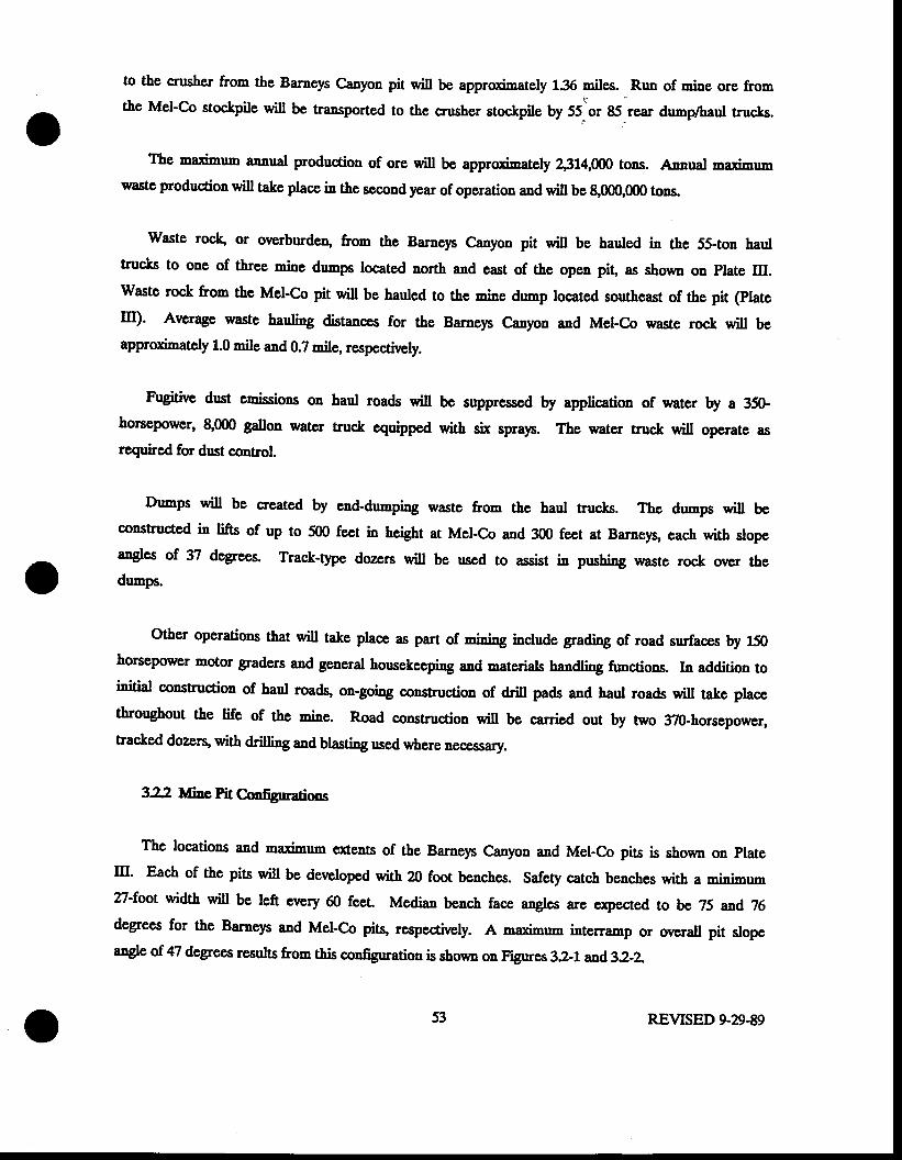
oto the crusher from the Barneys Canyon pit will be approximately 135 miles. - Run of mins s1s frs6the Mel-Co stockpile will be transported to the crusher stockpile by 55^or 85 rear dunp/baul trucks.
The maximum ennglt production of ore wi[ be 2314,ffi tons. Annual maximumwaste production will take place in the second year of operation and wil be 8,0(X),0(X) tons.
Waste rock, or overburden, from the Barnep Canyon pit will be hauled in the 55+on haultrucks to one of three rnins dumpg located north and east of the open piL as shown on plate ltr.Waste rock from the Mel-Co pit wiU be hauled to the mins dnmp located southeast of &e pit (platem). Average waste hauling distances for the Barnep Canyon and Mel-Co waste rock wi[ beapproximately 1.0 mile and 0.2 mile, respectively.
Fugitiw dust emissions on haul roads will be supprcssed by application of water by a 350-horsepower, 8,000 gallon water truc,k cquipped with six spra),s. The water truck will operate asrequircd for drst coutrol.
Dumps will be created by end-dumping waste from thc haul aucks. The dnrnps will bcconstructed in lifts of up to 500 fect in heigbt at Mel-co and 300 fcet at Barneys, each with slopeangles of 37 degrees. Trac;k-6,pe dozers will be used to assist in pushing waste rock over thedumps.
Other operations that will talc place as part of rnining include grading of road surfaces by 150horsepower motor graders and general horsekeeping and materials handling functions. In addition toinitial construction of haul roadg on-going construction of drill pads and haul roads wiu take placcthroughout the life sf ths mins. Road constructioa will be carisd out by two 37Ghorsepower,tracked dozers, with dd[ing and blasting ued where neoessary.
322 Nfme fit Cmfigurations
The locations and maximum ercents of the Barneys Canyon and Mel-Co pits is shown on plate
m' Each of the pits will be developed with 20 foot benches. Safety catch benches with 6 minirnsp27-foot width will be left every 60 feet. Mediatr bench face n,,gtcs are e:rpected to be 25 and T6degrees for the Barneys and Mel-Co pits, respectively. A maximum interramp or overall pit slopeangle of 47 degrees rqsults from this configuration is shown on Figures 32-t arrd32-L
53 REVTSED 9-29-89
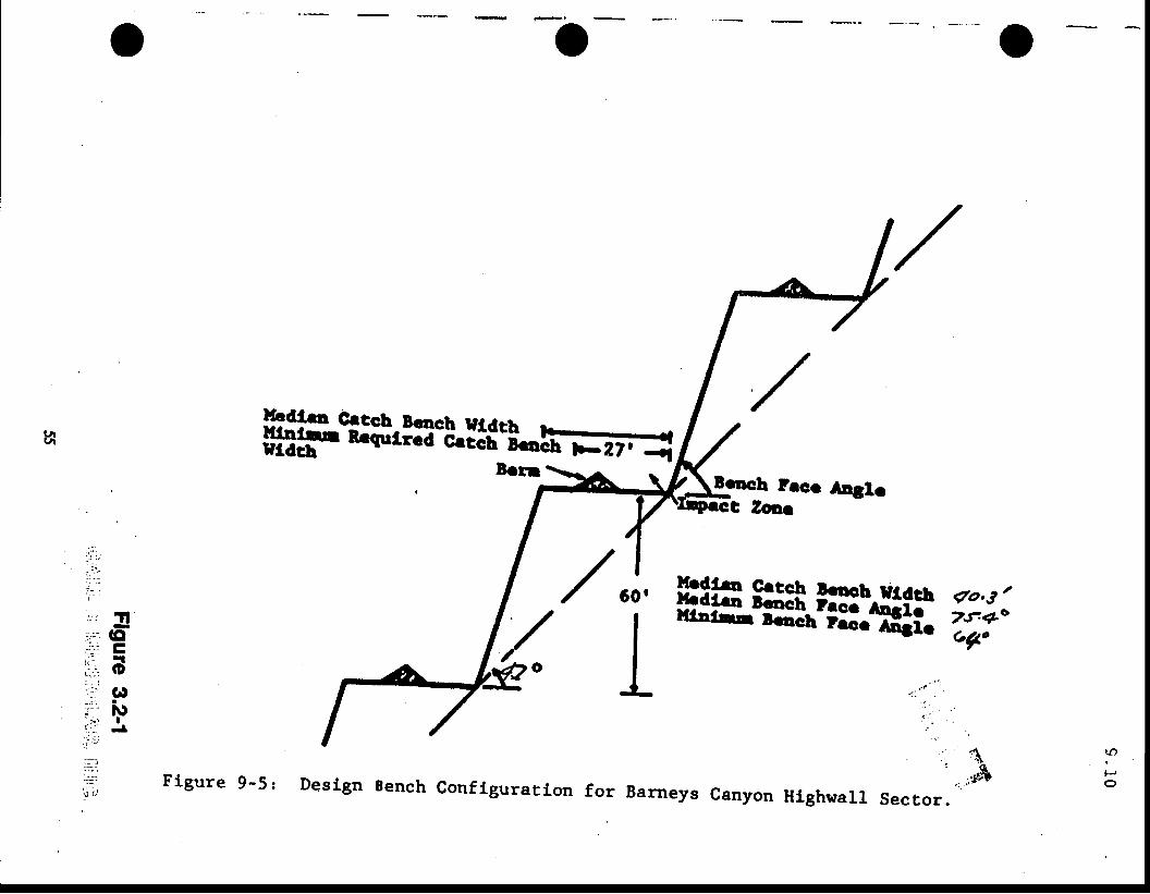
t,tt, Hl$tffi'm"Lllf 'l-*-;E
lcrr \--r. rgrncb lecr Aqh
C Zoar
: l ' ' ;t . - 1! .-,
'-:;r 1f-:'.. lGl-l= trrl: 't
..r', O; . . )'::r (t:.' ilt' i r
Ic:. -- rli : i
::-l
,=t
l ' . ' - . ,
/
HRffiLH.#T i?i:
, .
t ,, rnfrfor Barneys Canyon HighwalL sector.
iJ)
l J
oFigure 9-5: DesLgn Bench Configuratlon
s $ii$'i:il*l:i"Ll:f, 'l*"*EEBench pecc Anglc
t Zoaa
f r60 '
I; -l ,:.: -f -d--
nr 'llE ; E
_(o,2. C= : -C' oi:;:; Gll=l iur '- r;*' N.? t ; ,e ' ! '
:-j
=L:-
:()]t '
HR8ffii,.{i:ifiii ?i,,n
Figure 9-4 : Des i6n Bench conf igura t ion fo r Me l -co .
The interramp slope design at the Barnep Canpn pit wiU range from 38 degrees to 47 degrees; theMel-Co pit is designed at a uniform 47 degree interranp angle. Present surface topography andultimate pit cross sections for the Barneys and Mel-Co pits are shown in Figures 32-3 & 4, asd 32-5 & 6, respectively.
323 fr. Sloec Stability AnalJris
Pit slope stability has becn analyzed based on the pit configuration discussed in section 322.Rock fall and large-scale slope failures were considered (Call and Nicholas, Lgt37). As a result of thisanal)'sis, the safety benches described aborre, combined with safety berms, were designed for controlof rockfalls. The bsnches will be constructed with berms located Tl feet from the bench face toprovide a 14 foot wide impact zone. The berms will be 5 feet high, 13 feet widc at the base andhave slopes of 13 to 1.
The stability anal)rsis indicates that large-scale slope failures 6rs untikely. ffus mins witl beoperated in accordance with all Federal Mine Safety and Health {rtminisrstisa (MSI{A) guidetinesand standards for nine safety, whic.h include reguircments for pit slope stability.
33 Croshing Scrccring, Conseying aDd Stoctgiling
The crushing plant receives run-of-mine ore and delivers crushe4 agglomerated ore forconstructing heaps. The crushing operation is depicted on the flow diagram in Figure 3-11. Thelimia of the cnrshing plant etrend from the stockpile to the heaps constructed by the radialstacker. Fifty-five-ton ore haulage trucks trsnsport ors to a stoclpile located a-djacent to theprinary sprshing plant. A rock breaker is used to break oversized rocks. ore is reclaimed from thestockpile by a Caterpillar 9888 front-end loadcr and placed in a 35-ton crusher fecd hopper whichdischarges to a vibrating grlzz:ly feeder.
GtizJy oversize @ar separation is 6ve inches) fals througb an enclosed chute directly into a42-inch x 48-inch prinary jaw cnrsher. In the pringa'-y crusher cavity, ore up to three feet in sizeis crnshed to ninus nine inches. Grirzily undersize is aiiscnargcd through an encloscd chute onto atl&inch x 232-foot belt conveyor le6rling to the secondary cnrshing plant. Size reduction in theprimary jaw cruher oocurs at a four-inch closed-side sening. Jaw crusher and grizzly rmdersize
56 REVTSED 9-29-89
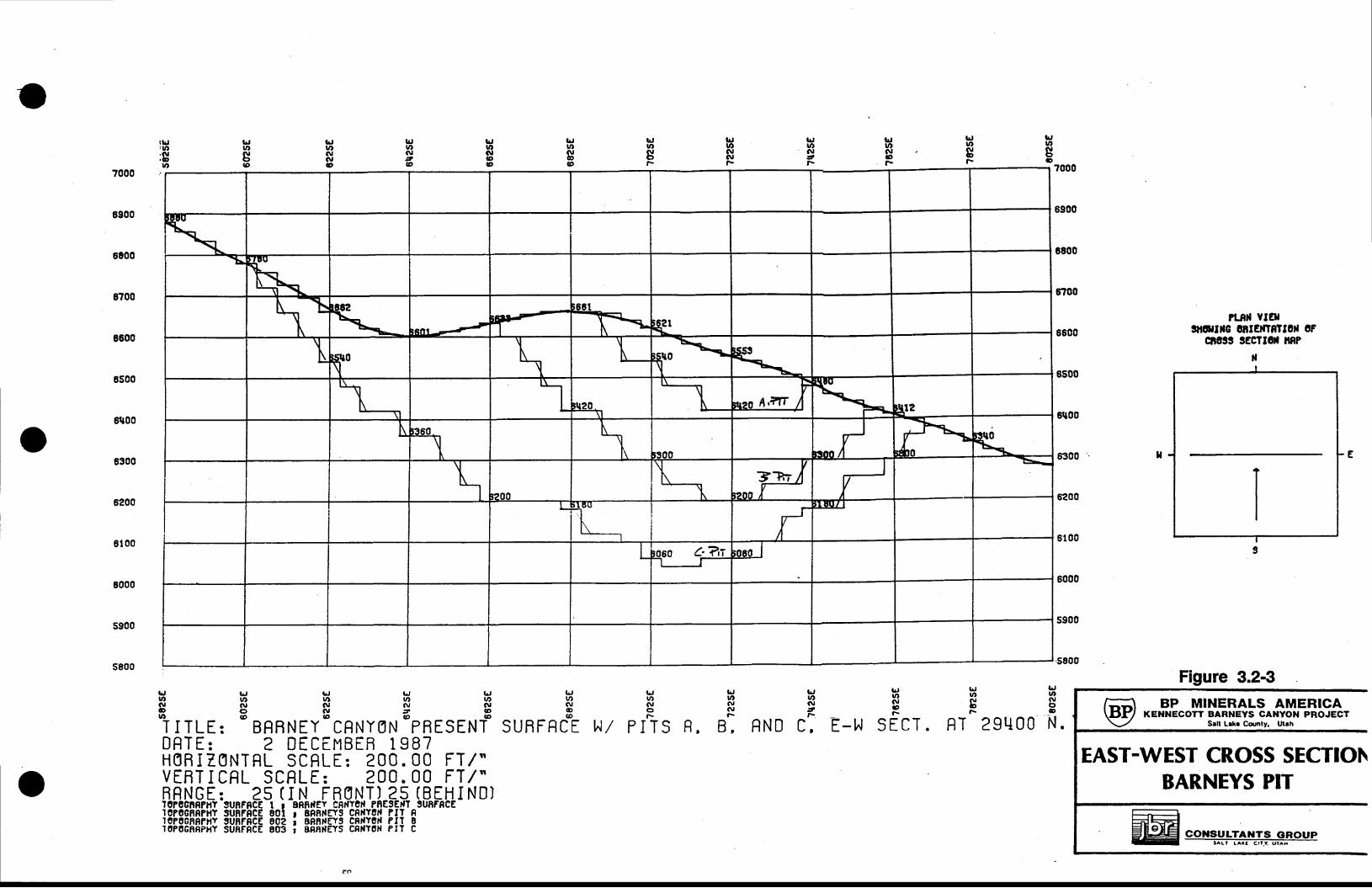
tr,tnl\lor-
Il,utolo
lgwGIN
tt tg,\
lrJu,GI6@
t JU'G|@o
lrjtt,a\lt@
t Jutg@
llrl:ut.|\|, ovt
G'w(\lolao
VEBT I CRL SCRLE: 200. 00 FT /"BRNGE: 25 ( I N FR0NT) 2s (BEH I ND)IoP0GnSPHY
-3t nF8CE t I ERFrfEv ggpvod PnESErfT 9U8r8CE
I0P068e?llY SU8FRCE 801 r EFBTIEYS CRilYON PIT RIo?ocRFFltY 9UnFFCE 00? i BBnfEYS CFrfYorl PII B]OPOGR8PHY SUNFRCE 803 ; ARRFEYS CNiYON PIT C
tr,wNJt-
?LRil VTAIs|attrc ontt|ffnrl0rl 0F
cao$ legrtar ilRP
5200
8100
6000
5S00
s800
6200
5100
6000
5900
.5800
LJlrln,t)o
l ! a
lrjt )(uo
lr,tO(\IJ
nt v 9
LJ u lJ lrJ LJu, v, rD u, lr)( \ | N O t a \ r n ,o c ) a \ r t @U . ' @ . o @ @
T I TLE: BRRNEY CRNYON PBESENTDFTE: 2 DECEI"IBER 1987H0R I Z0NTRL SCf;LE: 200. 00 FT /"
f.Jt to,oao
SURFRCE
L,u'.\Jot\
IA/ PITS
l^Jv,No,F
R, B, RND
lr,ui,(\l
ot\- F r l e r n T
L - ] ^ I J L L I r
o
\
h=\-
K*-cos-l
\ i-' \
q=-_
\\ l
"l',zo A,ilz
t\ sr2
\ *rrf F Blr0\q
\ 1200 fl rL] ' I 0 ( J
:i
i\ ftr-Elll_l
Lboso ?din_t-
tlI
3
Figure 3.2-3BP MINERALS AMERICA
KE}INECOTT BARNEYS CANYON PROJECTSetl L.k. Corrnty. Utlh
EAST-WEST CROSS SECT!O[\BARNEYS PIT
RT 29U00
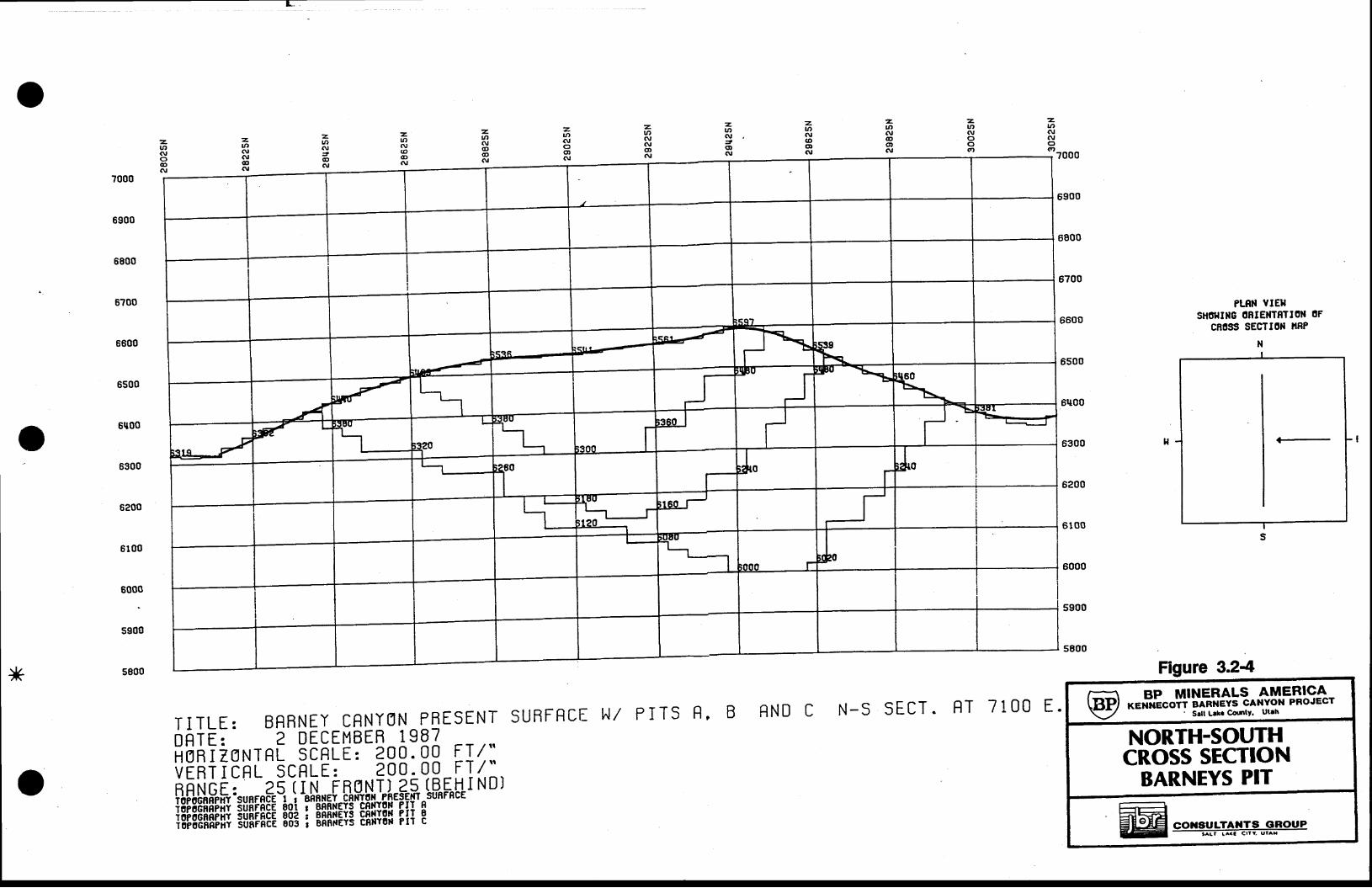
?000
zrn(\,Jo(\l
zrt(\l(Do(\,
z.t to,oct(.I
zat,AJcto(\l
ztt'GI(\,o
lzooo
6?00
6900
6800
6600
6500
6300
6200
6100
roo:
5900
5800
PLRT{ VIEIISHOfltilG ONTENT8TION OF
cn0ss sEcTIoN tlRPNI
<l-
I
s
Figure 3.24
6U00o
T I TLE: BRBNEY CRNI0N PnESENT sURFRC|:ONTE; 2 DECEMBER 1987HijAizsNTnt- 5cRt-r ' 2oo - oo F-.!/.:VEHiIcnl 5cnLE: ?oo - oq -F\1:
ftftHhftft ,urrfi*i*ik#,*tHl*i'*ffu*nl N D
IA/ PiTS R, B RND C N-5 SECT . RT 7 1 OO E.BP IiJ|INERALS AME_EIC.A-
xex-xicoif banxevs cANYoN PRoJEcr' S.lt L.k Cor,ntY. Utth
NORTH-SOUTHCROSS SECTTON
BARNEYS PIT
@| coxs#;tr+Erert u*rou P
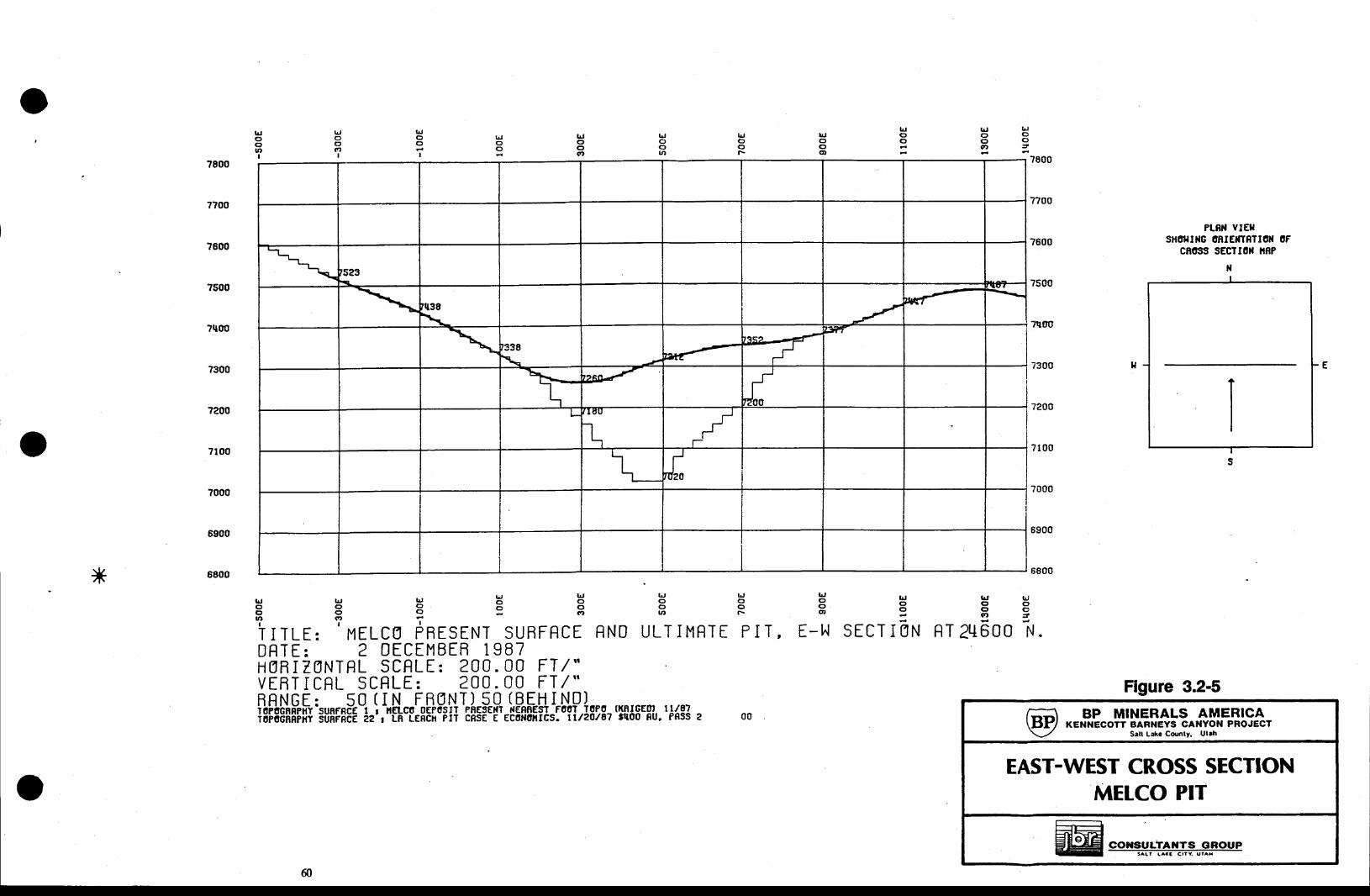
oi^J lrJo C )c r og r =-
trloo
tocttt,I
luooo
trJoo(r,I
ldoot\
LJooIrt
lrlooqt
lrJoo
lr,oo
I78007800
7?00
7600
?500
?qo0
7300
7200
7100
7000
6900
7?00
7600
?500
Trltlo
7300
7200
7100
?000
6900
PL8}I YIETIsHor{tt{G 0RrErTSTI6[ 0F
cR0:t!t sEcItoN i8F
Figure 3.2-5
r d l . l . t L , u Jo o o c ' oc r g o o c tftt g, a
{q}
t l l
T I TLE: MELCg PRESTNT SURFRCE RNDDf;TE: 2 DECEMBER 1 987
ULTII,IRTI PIT, E-t^I SECT I ON NT 2LI
tr/87PRSS 2
lr, lrjc, (fc t o( t t 3
a
A n n r lO U U I \
kctoa,
frjoou,
frJc,o
HORIT1NTRL SCf;LE: 200.00 FT/"VTRTICRL SCFLE: 200.00 FI/"RRNGT: 50 (IN FR0NT)-s-0- (BE-ttI-N0l--- . .-^----ioFitbhnletri'sunFnclEt i rEtco oEPoSIT PhEstrr lqnaEsr-Fool TqPo- (l.$tqEofi;F66HHhiii stiHFHfE ia-r--LB-IEAcil etr cnsE E Ecailotlcs. rr/20/87 tq00 8u,
L
t--1_
\ '523a
\ 'q38
\ -'t--
't{'''r
\ 1338
\tal1'.
t3<" {
{
,ffi
h-1
ngf -
ilL
l_I
-
'r-'l -tdza
NI
s
BP MINERALS AMERICAKENIIECOTT BARNEYS CA}IYOII PROJECT
Salt Lak. Co(rlty, Ul.h
EAST-WEST CROSS SECTIONMELCO PIT
COIISULTAIITS GROUP
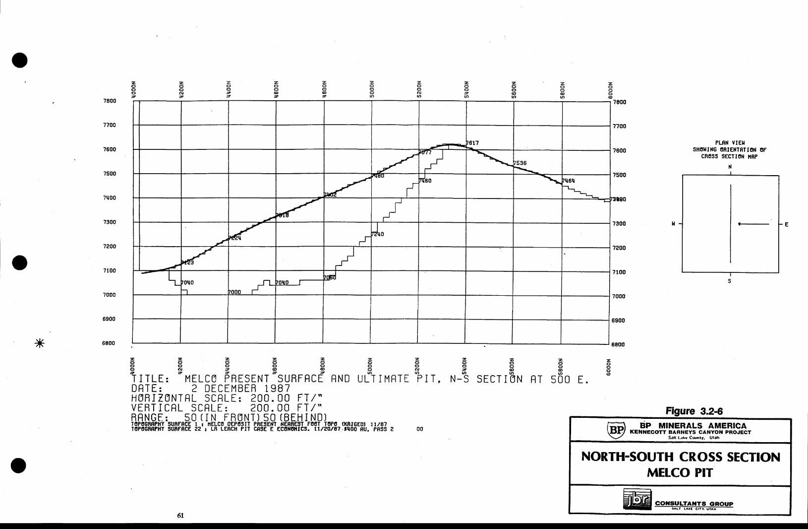
l
z.oo:tLO
z.(fc,c,
z.oo(\l
tt)
z.o
ott)
z.ooG'
z.C)oat
z.oo
z,oo(\,
z.oocE!ln
z.oo@tlt,
z,ooc)6
?700
?800
?600
7500
7q00
7300
?200
?000
6900
6800
7100
PLRN VIEIISTIOI{IIG ORIENISTION OF
CROSS SECTION IIRP
NI
s
|(
z, z, z. z, z,c ) o o o oo o o c r oo $ r = @ @J = = = =
T I TLE: MELCO PRESENT SURFRCE RND
z.oooll)
ULT IMRTT
z.oo.D(rt
SECT I g
2oo(\'rt)PITr I t ,
z,octltt
N-S
z,(3oort)
N RT 5OO E.
z,octc,@
DRTE: 2 DECEMBEB 1 987HgfiITANTRL SCFLE: 200.00 FI/"VERT I CRL SCRLE : 200 . 00 FI / "BRNGE: 50(IN FR0NT) 50(BEHIND)T0POGiR?HY SUAFRCE t r iELCO 0EPOSIT PfiESENT NEB8EST F06T T0P0 (KRIGEOI rr/87I0P0GnRPtlY SUffFeCE 2? r LR LERCH PIT C8SE E ECOlf0lllCS. tl/2tt87.fl00 8U. PRSS
Figure 3.2-GBP MINERALS AN'IERICA
KENNECOTT BARNEYS CANYOH PROJECTSalt l-;rlc Cwrly, Ulah
NORTH-SOUTH CROSS SECTIONMELCO PIT
FE <EE COilSULTAXTS OROUP-- f f i
00
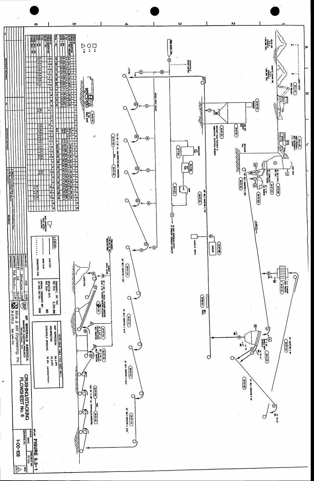
ooCD
it Bi tiEl on!
\
tllitrr6i ry
TEJ\Bu'
Biu
giflrI t
8EfiilE T
1flE-
I
PI
d3 B**E *EF; FI; !
N g
L arHb
I t
i li lrllEpt
=Ea7Bi:EI
ocBHr
8Fr tHH;1 8 .
n
B
HEE3E$i n i F i' 0egqezo
BFF( l o !r q q
t;t!
{3
ml
L=
e{
I3.tl
oc8m(!a(oi ll r
nlAE
lFli v l
'+i-l( tri i: i
fi::FIEHInt
EE:Bslo l
I
Ao lI
rnf,(of,oo
-(o
o
ooBEroooa
iI
FIta
6tfr
prducts are conbined and transported via a 48-inch oonvcyor to an eigbt-foot x 2Gfoot double-deck vibrati'g screen Capacity of the crushiqg facility is 650 &y sbort tons per hour. oversizefrom both Ecreien declG is conveyed by a serias of 36inch coaveyors to a five-and-one-balf-footstandard cone crusher which is operated in closed circuit with the scrscn to producc minus one-andone-half-inch product.
Ccmeat &om a 15&ton capacity silo is dumped at a controllcd nominal ratc of around tsnpounds p€r toB to the minus-one-and-oue-half-inch screen undersize product. Tte combined ore-ccment Eirlue is transportcd via a conveyor to the fiw 36inch x ZL,foot agglomeration oonveyors"watcr is added by spraln on the fir,c conrclors to produce an agglomeration product suitable forheap coustruction" Agglomcratioa is a technique that conobines the water and fine cerncnt wi& theorc to facilitate inprorrcd leaching and gold csraction" The moistue content of tbc agElomeratcdore is controlled to approximatcly 10 to 12 percent. The agglomerated ore is transferred from thecrushing plant to the upper cdgc of &e teach pad area via interconnecting 36inch overlandconveyor belts. The last overland oonveyor discharyes ooto the first of a series of 28 portable 10sfoot-long @nveyors for subsequent feed to a 100''foot radial arm stacker via the transfer conwyorand a shuttle type stacker feed conveyor. The stac&cr progressively retreats up the leach pad tospread ag9omerated ore evcnly on top of the overliner blanket or previors lift. Clanide solution isspraycd on the ore to initiate the lcaching of gold.
Initial plans call for the crushed and agglomerated ore to be stacked in threc lifts of 17 twteach to a total heigbt of 51 feet. The specified lift hcigbt Eay be inceased or decreased in thefuture depending on metallurgical results. The maximum ore heap height is linited to l25 feet.
To ensure heap stability, ." or*iro [fts arc stacked, thc toe of each new lift is set back apre-detcrmined distance from the crest of the prior lift around the fuIl periphery of tbc pad.
Watcr spra'6 at conveyor transfcr points are patt of the dust suprassion system that controlsboth moisture content and air quality.
3.4 Irachiqg
Ore will be transferred from the aushing arca to the leach pads in a serias of fixed overlandoonveyors' Thc rarlial stacker will stack the ore into l7-foot-high lifts on the previously preparedleac'h pads. The ore will then be sprinkled with a weak (1 pound NaCN per ton of leach solution)
62 REVISED 9.D.89
sodium cyanide and sodium hydroxide (NaOH) solution. Wobbler-t1pe spray heads will be used. The
solutions wi|l leach the gold from the ore as they percolate tbrouoh the heaps. The resulting
"pregnant solution" wilt be collected on the pad and piped to a lined pregnant solution pond located
adjacent to the process plant at the east end of the property. Pregnant solutions from the pond
will be pumped to carbon columns located within the process building, rvhere carbon adsorption will
tate place. The loaded carbon columns will then be processed further thtough desorption,
elccuowinniag aad 36fining. Tte leach pads, solutioo ponds, aad process luilding locations are
shoc/D on Plate ltr.
3.4I lrac[Pads
A total of approximately 170 acres of pad area is required owr the life of the projec! assuning
that three l7-foot tifts of ore will be placed on cach pad- The pads haw been designed and
approrred by BWPC for a maximum orc heigbt of I25 feet. To rcduce capital outlay, thc pads wi[ be
constructed sequeatially as nceded with the BC-l leach pad constructed in 1989. Other pads will be
constructed in later years. The general arrangement of the leaching facility is sho*u on Figures
3.+1. A generalized drawing depictiag itre rnajor oonponents of leach pads is shorm on Figrre 3.*,
Z Leach pads will be sized and arranged on the site to reduce the amount of grading required forpad foundations
Leach Pad Foundations
Each pad will first be graded to produce a firm foundation. Grading wiU be preceded byvegetation and topsoil removal. The topsoil wil be placed in stockpiles for frrtrue use inreclamation of the facilities. The pad foundations will be built with cut and fill techniques wherethe alluvial soils will be excavated from the tidges and placed in the low spots as engineered 6lts.The backfills wiu be raised in horizontal lifts not s:lc€€ding &inches in thickness, conditioned withmoisture and compacted to W95Vo of na:rimum dry density (see Appendix E for full specification).The general grade of the pad foundations will slope along their long dimensions at 6% naximun andless than LVo along their short dimensions so tbat each pad will have its lowest poiat in a corner for
ef6cient solution collection (Figure 3.+3). Stability analyses performed by Sergent, fhuskins sndBeclnilith (1988) indicate that the heaps will be stable. fte detailed grade of the pad surfaces willtypically accomnodate the topography through the use of long terraces which themselves have slopesalong their long and short .linensions for drainage of solutions (Figure 3.+3). The fi'ral foundationgrade forms a sub'base with a permeability of less rhaa s;. equal to 1 x 10⁻⁶ cm/sec upon which aleak detection slatem is placed"
63 REVISED 9-29-89
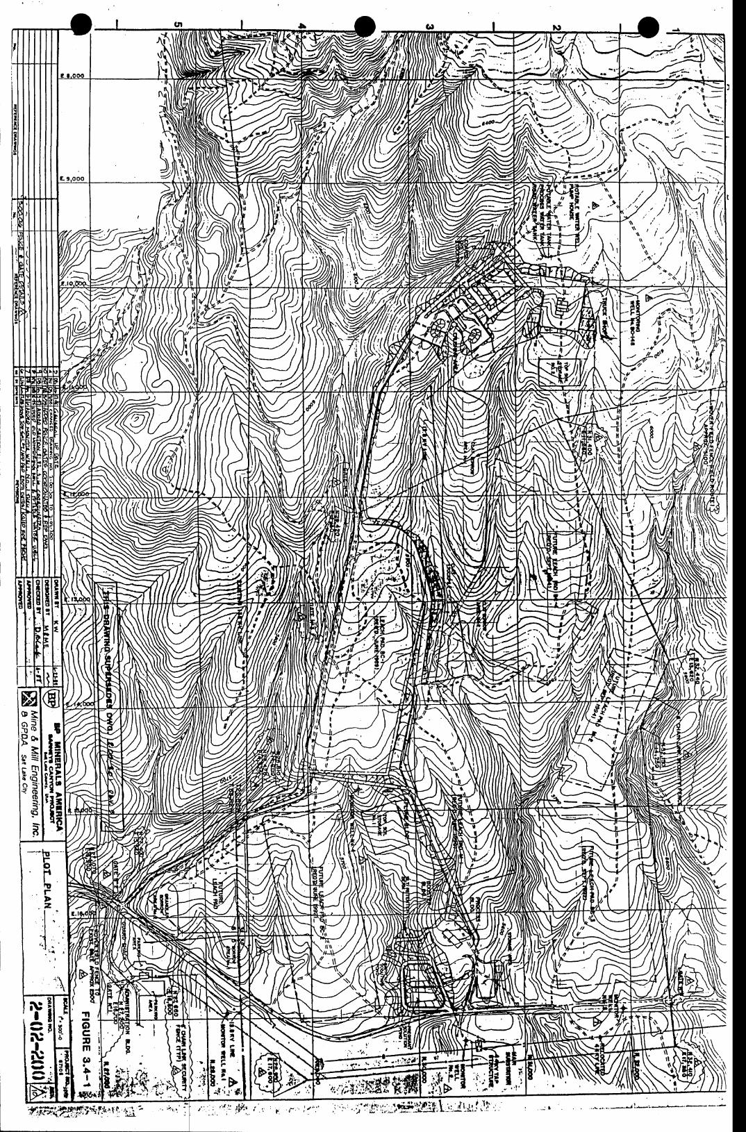
N
Nffi
NI
- :Y E
i \ : '
*Fb r,y d
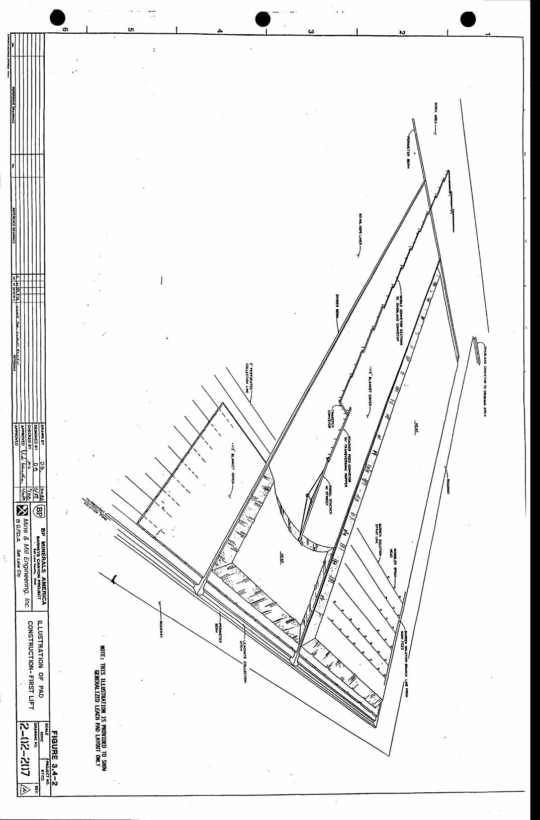
octl
o-
{c;
ItIIG{aoaI
IIF:Tr_ta
{
sf,oOo
R=rnf,ef,oos(o-f,s)
s9l
B
rt
FLl.o
aq
O FO FZ Fq64ni!-99
3q. 7 gB
E( '-rl{
NI
NI
N
{
sf,T >-r-l
n{I
Et
;na* -r t FS FF Ei r (4
EEF=O -
EAEE6 OF,a* l
loC!m
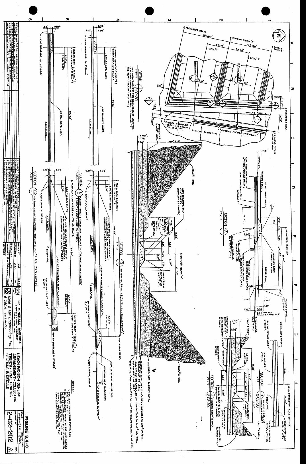
cC Q ( L .
?
illniild t
o
1aai l tt oI t
i iF O
tq
dI
. o
I: tt,oF
Frtt
obo -
izes,Fiiq4o.oo
il
t3IeF
bfntlro.J
{B
:apzt3oF
t$toito
TEto6F
d
I]
,r,oilcxAF
'rto.0|n
zmP 6i;t
f r' < !
2,.o
8r
inef,
l . ! o
EHFa
f r gzrEZe o
Poj
t
EIt|not
ot,t|l.
I
Fi, c
;IS FF.9"^ - n? t
Fcran
tttItoFotl
,
co,rao!ar
J
F
c517FE;n'r Ei
ii"g7ni " 'tatn
tiG@o
Ef it .
Fra
;n
o
II
ra
aca
Filri^Ioit.
InI|o
FoRaron(irr(
a1.,oF
t,
tf,
roItp
I,r
3q?5:.
iiiFgf;ilflii
\i953
ililiifllr
{ .9,zad r l
fFr , |d '
, > ld(|I t d
i",f F 't!
" .li$iHiiii
ififf1'iH
!oF
tItnP1'F,,t!z('
nlpa|r,
a
Hl6lz
I4:|Ltotoatala,.P
r
El 9l!,I nI tt >I t
IFllt ot | !l >l ^ '
t\,2;ie rSei'sEFF:^!? r .s - l^ lo n
a9!;9Ea 1o o
1.\ii*F/r
q7II,!
I,noJo
6,t
,lnPt
Pfi7c
7oF6
rt^Ja,'oo
rtotcInrt
ftva
Totr
c.Fr.0d,9
lP,I
;\coo,,o,r
o Bc iC 6< l
,.ct6)0
3octmC'a
II
C!
c,Fi71 0t \
4
6z
z
c Fi 7,, ,
otnP
i6a tt 7
cPi v6 ora
odI
k'l
Hp
tI m
F.N
on
,cu6<oEo9z,<gtAr
!rIt r IP l *a;.9r. f
ii iqc!22
lu'l'rs
7n
4ery
,,ll;
llsrlr rre {
'-\'5s "'","? t|};
Wriii',t t _
z.oo
!:9't.5d
3:i"l,?fiiJ. ,.'.
Io-
EAa6ie
[\e
EP('F
/-
P oJ,q
;6- e 6r Z
<lf,oh
=rnf,
Qf,oo=.f,
If,!-,
s9)
Bv,b-rso
oq
gHHiHF? Ff;frP8;3p
z
NI
y
NI
NAv
N
IoJ.
!'z
At the doqmhil margins of the pads, the pad surface will terminate in a solution collectiontrench that is ll-feet wide at the crest and 2 feet deep. Outside of the trend there will be apcrimeter berm that is 2-feet high v,,ith an 8-foot wide toe (Section d Figure 3.+3). The bottomcorner of each leach pad cell will be equipped with a leachate collEction pipe erending through theperimeter bern @etail 6, Figure 3.U). This pipe will be made of welded HDPE and will tnnsportthe collected solutions to the leach pads.
Liner Irak Detection Srntem
A Six-inch-thidq high permeability pad drainage s),stem is installed above the compacted low-permeability subgrade. The purpose of the leak detection s)4stem is to alert operations personnel tosolution losses thro'gh the HDPE and clay liners. T:pical cross sections of the pad lining and leakdetection system are shown on Figure 3.43.
Irak detection under all areas of the pad is accomplished by monitoring the presence of anysolution 0ow in a closed HDPE collector pipe which connects to a series of two- or three-inch-dianeter comrgated polyethyelene pipes resting on the subgrade (Figure 3.+t. Each pipe exits atthe side of the pad- The leak detection pipes are factory-miilsd with 0.66_inch-wide slots placed ontl0-foot centers. .d rninimsn slope of one perccnt is maintained on the leak detection pipes. Eachsix-inch HDPE collection pipc at the margin of the leach pads is joined to the non-perforated endof the leak detection pipe by a polyehtylene snap adapter. The other end of the non-perforatedleak detection pipe is joined by a pipe sleeve to its perforated equivalent that rests on thc leakdetection layer.
Leach Pad Liners
The secondary earth liner will be placed on top of the lea& detection system. This will be afine-grained clay soil borrowed from &e property near the leach pads. It will be spread in layersthat when compacted will be approximately 6 inches thid conditioned with water and compacted to95Vo of $e 6315fuarrm dry density as determined under ASTM-D698 (see Appendix E). Two layers willbe placed for a total compacted thiclness of 1 foot. The permeability of this compacted soil liner isexpected to be 1.0 x 10⁻⁷ cm/sec whicb combined with the design thickness, will assure that anyEeePage thtough the primary platic liner will be essentially stopped by the secondary liner. Thisliner will be erended to the perimeter berms as shown on Figures 3.4-3.
67 REVTSED 9-29-89
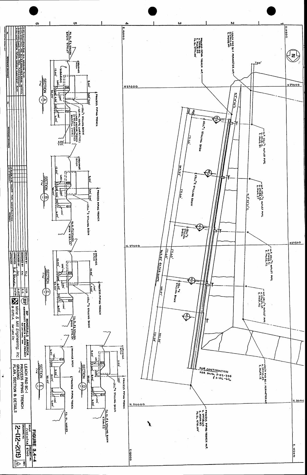
Srr l
iiiri r8IE_6
1,
tF
{ r ir;6gr;' ^o Duoo
FI
!n!j
IFF
tg
I
8ta|ottaG
iC
tFiiie3it5?
r-l 1t l
tNl,
ELcct
6'z
t
8Ittttt3o.{,aalrz,
9 gA 't 9
ott
ffi otoF
tt,
r.Ece
vz
n
F,D
9f?to9
t a
t8,r(,r
Itto{tanFt
IoC!m
I$
i'I
o'6.cb
tIt,co2t
t
6tlo
!t6I6
8t
I n | l| ' - N P
! F i r| {lib J-vt
P g{7ile
ttft
-_-____.I
t ' i z t' - i t
i ipi?- ,6'^t t
J ocrn/
r P l lirinI o d oo s @ od 3b:s_t
It2:o
o
Nlt 500
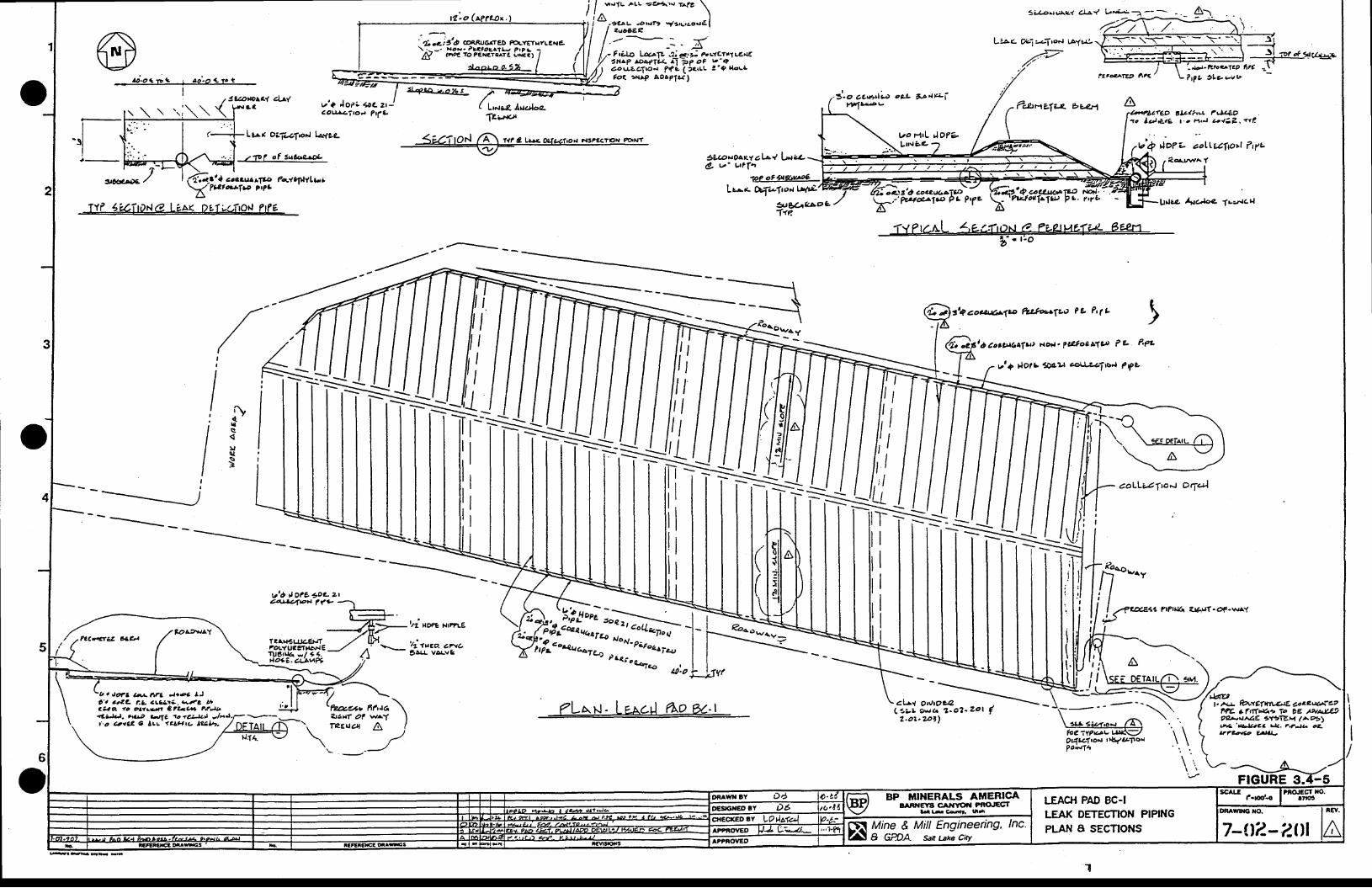
< - a . 2
. c..e;ttd coRRrJGrteD a\TETHYLcNe\1-- . xax. ?3uocr1ie ?r?r
N aate tOPCx(TnaTt, r.r{€a)
Lnrr*' lrraloe
ao< )x^P AoAPls)
3i-/€ta^zi a.bl
L'*L *-i-Arorr t.Ayrrg
?aFsfE.it A?e
ftanztiz buJa AJ-o ce.*i.eo astY4b.isv
,4,attLiv'Q Aott loLzt-aote.-i|o'. ?tfL
L a^ ( OaT...,I ,Firl layee-
.1rl of 3$b9^DL
lt 1 ccerl.;r. r7p ?4.ttfilla..-?tltosf.p ?t?3
fzr,:.t<tt
<'"nprl 6 t,ar*wt*rr"-
szrotgaztalsl lazl4L t 'v t?( . ,
ptg!3@-Lzt* Drf*lroaltfiL'
+?^o''4
a2ot,taeltt) lvti.l'{loelLT',) p'.. 7ryL
l -
; - \
foe'il?t/)v
'4.,+LlfCP alzl?tt ?J.;ttO1c lu ) l€ : te r . . r1 ,J - {37 ,a le
v'Q ioez aollezlptt l17a?errnaY
aoLLrZTtoJ Ot-t4)
. ; )
T'ff 4zTt,ile. Le^K Dtl'^Litot! ?fe
/
,lHnIII
skcow*1e ftslootlto ?L hlL
o)l'bcot,,('aft|) Hoil' ?a4oc^19 ?e' P'PL
rr'; rlolr eu 4l,'4ilo"l Pfc
!I
IIl
-.i
FaAt^.,rAY
ry{.st:<l\tes
?a(6net 4,b1
F.S.-iF-= I
I
I- r
t l
l\--
_ _ _
vt6 | O?e 3oz zr
ifiiltii;1;:J /, >\_ ;'.U.,LiE
Ao9e.aluft .7-
1z 'ac l . - | r ??e - \
a - i --=g:>tti toee pt'zre
-E/TrAN;ul4.E|JT ./ lFl;oxiter-vale _,/ r- \.-- !a-!!1o.:.?.?c
:ir;;"b"7^4 ca^.
- ' , coL?T,c;
tti:: ;::: N o N - P eF o 4^ i4,_t. t )
pr .areCe7?-o
UiO ,I
l ,,II
: t
fLrrl- Lararl 6o e t ctJt ovto;4L t t . c , s . . ? -o? -Zo l F
gt4u-1to/ trtq,'4lloi
?o.fTt,
6
o
-*YL ^Lt =E 4"'" t^fe
\
lA,-o*r -,.tr t.,...o.a1I I 2so6€?
| -NETAIL /.1-\ \
-lt1.4,.-E-/
v * - 4 / \(*o'u" nnuo\
2r.Ht aF w .( I'i Ta€lat a t\---^I',.
-.-z
l ' a
rJdEt. t+ dt efn a-elE .-c a elala?
?E +rffrr'4,'' 1o be AfuAY*9?gr.r r\a1e 3.(91EFt ( %>!+e,'J*tZa t4.
".?-f4 cZ-
LfTbt@ g,t{J..
LEAC}I PAD 8C.ILEAK DETECTION PIPINGPLAN A SECTIONS
BP }iINERALS ATIERICAAAR'|EYS CAIi]TOAI FFIO'ECT
adl-Coda t,ti
7-1.12-2lrlMine & Mill Engineering, lnc-& GPDA s;,tt uke city
/ - ' -">. - . / ' \'(i)-g Loc,tlL ei *:>- p'L'tEtrIL€,{€:xrP roa+1ix. ^-7ip oF b'Qlatlzalrod Pf a itcrrL ! '9 {ora
.Ja?3 caA"j e.ea LJO-a a.az t3. a!c3r3. L"2 Bta?e ao ?L1ren c?2-a4 ?it/l,,i{'3)d. ho.9 btlz 1o <b).) .lFJ...'-o Qrat e lrr a^ceto t91Yt. /
2.o2 .?pr )
The clay for the secondary liner will be recovered from borrow pits on the Baroeys Canyon
Property. Three borrow souroes have been identified thus far and their locations are shown on
Plate III. Further pit development will depend on the resources available at each of the existr4g
sites. Clay pits 1 and 2 have been partially developed. The esent of current development and
esrirnated ultimals pit size is shorm on Plate Itr. Pits will be expanded or developed as demand for
liner materials arise.
The primary liner will immsdhlely be placed on top of the earth secondary liner. The primary
liner will be 60 mil HDPE installed according to the manufacturer's recomnendations (see Appendix F
for full specification). This material will cover all interior areas of the pads, as shown of Figures
3.42and3.{3.
Solution Collection
The final step in pad construction will be the installation of the crushed ore blanket, oroverliner, on top of the primary liner. Solution collection piping will be installed on each cell prior
to covering the liner with overliner. The piprag will consist of a tbree-inch-diameter comrgated"perforated polyethylene pipe spaced at zl&foot centers (Figure 3.+2). These pipes will connect toan eight-inch-dianeter polyethylene collection main which will run downslope to the discharge endof each cell. The blanket will be minus 3/4_inch cnrshed ore, produced at the plant crushingfacility, which will be trucked or conveyed to the pad and spread to a thickness of approximately 3feet. The overliner will function as a protective cushion separaring the primary plastic liner fromthe overlying ore. The crushed and agglsmssated ore will then be stacked on top of the cushion.
3.42 Solution Conveyanes
Lcach solutions drainiqg from the bottoms of the heaps will llow in pipes in the solutioncollection tre'nches along the margins of the pads to the low points of each cell where the solutionswill be routed into HDPE pregnant solution pipes. The pregmnt and barren solution pipes will havesecondary 5pn[ainmsal a lined ditch which flows toward the process solution ponds. pregnant
solutions entering the ponds will be routed through measuring flumes that will record the flow rates.
The collection trenches will be HDPE lined ditches from the pads to the solution ponds tocollEct any leaks of solutions from the pipes, as shown on Figure 3.zt-4. These collection trencheswill be separated from the general site drainage by their lateral berms and will be carried under all
70 REVISED 9.29-89
road crossings with culverts. Thc layout of the trenches will provide suitable grade (LVo rninimum)
so that any leakage will be conveyed in the trenc,hes back to the process solution ponds (Figure 3.+4).
The barren solution piping s'sten on the heaps will co'sist of a l2-inch HDPE pressure main oneach cell' a network of six-inch PVC branch lines, and a network of three-inch spray PVC linesspaced at 4&foot intenals. InitiallX the sprinklers will 6s igsnninger-Wobblers" spray heads. The$snninger-Wobbler sprinkler is highly resistant to corrosion which reduces the risk of plugging orstalliry. Since it has a single moving part, the Wobbler also resists wear.
The spray heads operate between 15 aad 25 ponds per square inch and provide a solutionappilcation rate of .0025 to .gg+ gallons per minuts per square foot of pad area. yelomine SDR-21PVC is enployed rrring spline connections. The piping s),stem will be inspected daily by the leaching
crew. The Wobblers require occasional un-blocki"g of orifices. The leaching crew will survey thespray pattern and note non-performing sprinklers. After shutting docm the fsgdlineE the sprinklerwill be unplugged or replaced. The sprinkler system will be restarted after maintenance iscompleted.
Solution punping will be accomplished with submersrble-type pumps in the solution ponds.Outside of the solution pro@ss building pumped solution pipes will be equipped with pressuresensors which will irnrnsdhtgty and automatically shut down the pump should there be a break in thepipeline.
3.43 SohrrionPords
The process solution ponds are HDPE-lined bacin( located at the lowest point in the processarea (Figure 3.41). The ponds will have a total capacity sufEcient to contain the followingvolumes:
The working inventory of lEach solution. This is the combined vol,rr'e of solutions in thepregnant and barren ponds. Normal volume will be 150,000 gallons in each pond (300,000gallons total).
The drainage of leach solution from the connected heaps during a Z hour shutdown of theleach pr'-ping system. The calculation assumes a 2Lhour draindown volurne enters the
1)
2)
77 REVISED 9-29-89
ponds at the prevailing barren solution pumpng rate to the heaps. For cxample, at apumpiry rate of 2000 gpm, the calculated vol,mc would be 2"880,000 gallons.
The volume of runoff from the exposed, lined pad and trench areas that occurs during thelCI-n 24-hour precipitation event. Thrs is based upon 3.5 inches of rain. This runoff will
be a variable and will equal 218,200 gallons for each 100,000 square feet of bare plastic. .
The runoff from the leach pads. Due to the water storage capacrty of the heaps, it is655rrrns4l that runoff will occur only from areas under active leach. Runoff from the 100-year storm Q W inches sf irin) would providc 218,2N gallons for each 100,000 squarefeet under active leach.
The direct precipitation on the ponds during the 100-yr 2A-hour precipitation event. Thiswill equal 283,600 gallons based on 35 inches of rain falling on the 13),000 square footpond area.
A freeboard value of at least 2 feet above the level for volumes 1) througb 5) above.
The combined capacity of the barren and pregnant solution ponds is available for the draindown and51636 inflsws. The total capacity of the process solution ponds is 10,285p00 gallons.
The ponds will -have 3h:1v sideslopes and bottoms that are sloped to one low corner (Figure 3.a-6 and' 3'47). The bottoms of thc ponds will have a rectangular configuration and will be inclined at2'0Vo, then graded to one oorner where the pond leak detection collection sump will be placed(Figure 3.+7).
Ponds will first be excavated to approximate final grade. TWelve inches of secondary linermaterial material will then bc applied in nro 6inch compacted lifts (Figure 3.+6). Thepermeability, material t1pe, and placement techniques for this liner material will be identical tothose described for the leach pads in Section 3.4.1. A geote*ile followed by a drainage g:ldmaterial will then be placed on the secondary liner (Figure 3.+6). The primary liner of 60 DdlHDPE will then be placed on top of &e drainage grid and anchored in trenches along the margin ofthe ponds (Figure 3.+6).
3)
4)
t
6)
T2 REVISED 9-29-89
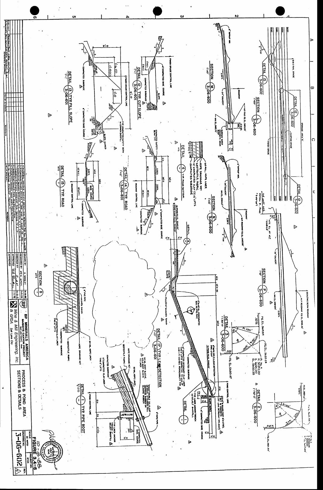
O,oo)
i3Ig.tp5
I"H
tr
E3iaq6
1
( in r
fgEAFH
I
EI
' t rsE
i?iiiilt,frF
i 'l:6sl
t n = l':i-61
g;ll ' t ! l
toI,EIFv
ulo' l$
$"li
l o- . t m
6.lc;
dPl{ 'o l<ol:!-h
l8
IEIpf
a
III!
P
F
I
f;z2
E
r l o' l$l F(Pl {t < .
lxl ot >l o
I , .
$llp' a
a
t r !I
f{gtsnItH rrc
1h r
,/
o
C
!
\_\
la? tm6 l o' lJ
lolzqD
glo lo l
t)
"1o
I2gt
o
!3do{
t{do{
F
rtN-
F
"EBo_
r
proI
I
2,. o
N . O" 1 ,o
TFFrEto{
mrhGNpNo
!fl pr" zp
k6 Erg8H"
FoN
I$
liilll: t !< 7 c
iht
--/ n96x
E
*
-.u)
tr
lI\
1 qi t' ! li t n- ' o
PE
ao
t$Et,
tBIhE
I!I,
I
IqpF
' r ' " i !, i * l i :i - oo; , o q
bo
Frgho
oIo!
?oI
R
omnF
N
1li0lotc
t;IElm
e'E ' it tliio =
RI5 ' lo laolR I-- trnf,(o5ooI .
g)
5o
s
$E-Fo
o
tqal"
U ) Tr n Eo o{ og86 a3 p O
R3t663
rrl
lrlI
rA
gfI
5)y
N
I
f
Do.
omIviflg.
Inil IInE
a
Iong
F' f l
iirlE1
fiit
D0I
ss
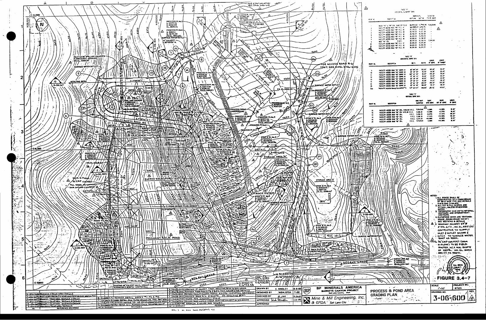
l id , .
Fa3. a2'atdL^n-q ! r a 6 i l b - r -
1:J ' r '
. : i : : r - : r . r - :1 .$ ' ) r r
3t:r.rj ::r.i:t(::::i {':{ 'r:9 a::s:: ' :>
t r : ! ' r ' a ' ! ' l r r F ! ! ! r . ? . :
. { : : : n E : I t r : ' i ' t . ; . . '
,E:: : - g= a: . r ' r . : . r :
t(::i: eg a: 'd' t t. t!
r ( ' . rn rC!: ! E'ra ' t . t . c
r f : : ! i ct t a: ' t ' ' t c
f(::!t E!5 a: 'lt' t.l. r'g t ' l ' t l r t . 0 . !r(r l t r ra: !s 4' i ' t . l - l :
r ( [ tn €rs 4 'n ' t . l . t l
rrlrm (:ls3 4 'X' t.t- 8t
,a. . ! f r .s.*
s: ! ! t : ,sr . t rr . : r : . : : x r : - :: l . x t . ; 1 . t : tn . r u . l { . : ! . rI . : ; .a x. I l . tt3. t l . r x. : t l .3rl . t l l . r l l . l l l , l tn. :r t -- l . ! r : .*x. tn.r n-x! .n! . t r-r n. I : . r
A
A
,{t[ln E-
tgj 'r
ntpll ill DutltE t$D
E!5 'gn ! t lF t
Il t
, l l
t ;
tIttlItl
$n- I-.
, l o'!/fl
it .t??
: .
J . .
ttll l
I tuta
L,!
t9
t r l l t t g s ' t t '6! r l, E t ! t [ E U ' ! ' m etgl l t gu' t 'q[ otrlun (:t! u 'L' dl rr&trtn Els s 'lr git Etantn G!!l D'!' ql rrat l rnEs.f qtr t ! !
ra:ll'' lClS O'!' Eil tsrgsbDtrou' l
{ 'ot ' r f t .B',f n' r d.s'
rf at' rr [.t't f n ' t r ' s . l l 'tt t' !' 6.e'il' tt' !' 6.t't f c ' r d. ! 'tt l'' r il.r'
ra aytr' ns'
n.n' l l . t 'r - t ' u. . l '
r t t .x ' t t . t 'n. t l ' la. l t 't .3r l l - f r 'r . r f r . l l '
til.n' rrt.tr'$.x ' l . l l '
,r.rt nf'
,/-
lt!o l t i l l
t'3na &
-l.L I.l'
{.nn r.n'.l,l.ll I.l'
ue! =i[t4 Eil lL
riiirn s s'r' :rr rrr.l t.t.l. r-s'r 4-ar&ilt g ta'!' rtr. t.t.:- l-ltl.n i.E
rnn lu.llrno r! cl
iiiiiii nas si.r. r^. t.t.l- t.s.! .t.tr[ .r..ri n'{iii i i i ieoiitt^. t.t.t- l.rtr'! ' i '6 r'L!l !'":iiiiin mrs s 13 tr. t.t-t- is lF .rr.x,l r.t'
, f ii /,'A
. : i . . -
!::*. :'; ..
?- \ , t r< D- - SU Ar l *< S<
The function of tbe drainage grd wilt be to capture any leeks 931 rrighl occur through ghs
prinary liner and allow leakage to be drained to the low point of the pond bottom for removal.
fhe bw point of the tcak detection s),stem will be equipped with a snall sump to collect the
socpage. pight-inch rlinmetff standpipes will be used to monitor the leak detection sumps forleakage (Fgure 3.+6). A probe inserted in the standpipe will detect any solution accumulated in
the leak detection sump. If confirmed that the solution is leakage from the ponds, the BWPC will
be notified as required in their construction permit.
35 lJach Solution Processing
Leach solutions will be processed in the process building. The buildingis location is shoum onPlate Itr. I-cach solution processing is depicted on the flow sheets shorvn on Figures 35-1 and 3-5-2).
35.1 CarbmAdsorption
Tbe carbon adsorption process is depicted on Figure 35-1. The leach solution from thepregDant solution ponds will be pumped to carbon columns, each filled with granulated" activatedcarbon, and locatcd in the process building. The gold-ganide complex will be adsorbed on thecarbon as the prepant solution passes through the columns. The solution coning from the carbonsslrrmns is the barren solution and will be refortified with solutions of NaOH and NaCN and recycledto the barren solution pond. The barren solution will then be pumped back to the heaps tocomplete the leach cycle. Fresh water as needed will be added to the barren ponds to make up forevaporative losses from the leach heap and the leach solution ponds.
When the gold content of the carbon is suf6cient for stripping the loaded carbon will go tothe carbon processing plant. The carbon will be pumped to an acid wash tank whcre the loadedcarbon will be treated with a 57o solution of hydrochtoric acid (HCl) to remove any minsla[ scaltbuild-up Ftgute 3.5-2). Acid soluble metals will also be washed from the carbon i1 this s1sp. Theacid wash solution will be neutralized in the acid wash tank by reaction with the natural carbonateminslxl5 on the carbon The metals that were dissolved from the carbon will therefore beprecipitated as hydroxide sludges within &s tnnk. This dilute sludge will be rinsed from the carbon,passed over a fine carbon screen, and pumped to the chemical waste sump. Fron the chemical wastesump, the sludge will be pr'-ped to the active barren pond where the sludge will bo mixed andpumped to the heap. If the acid is not adequately neutralized in the acid wash tank, washed carbon
75 REVTSED 9-29-89
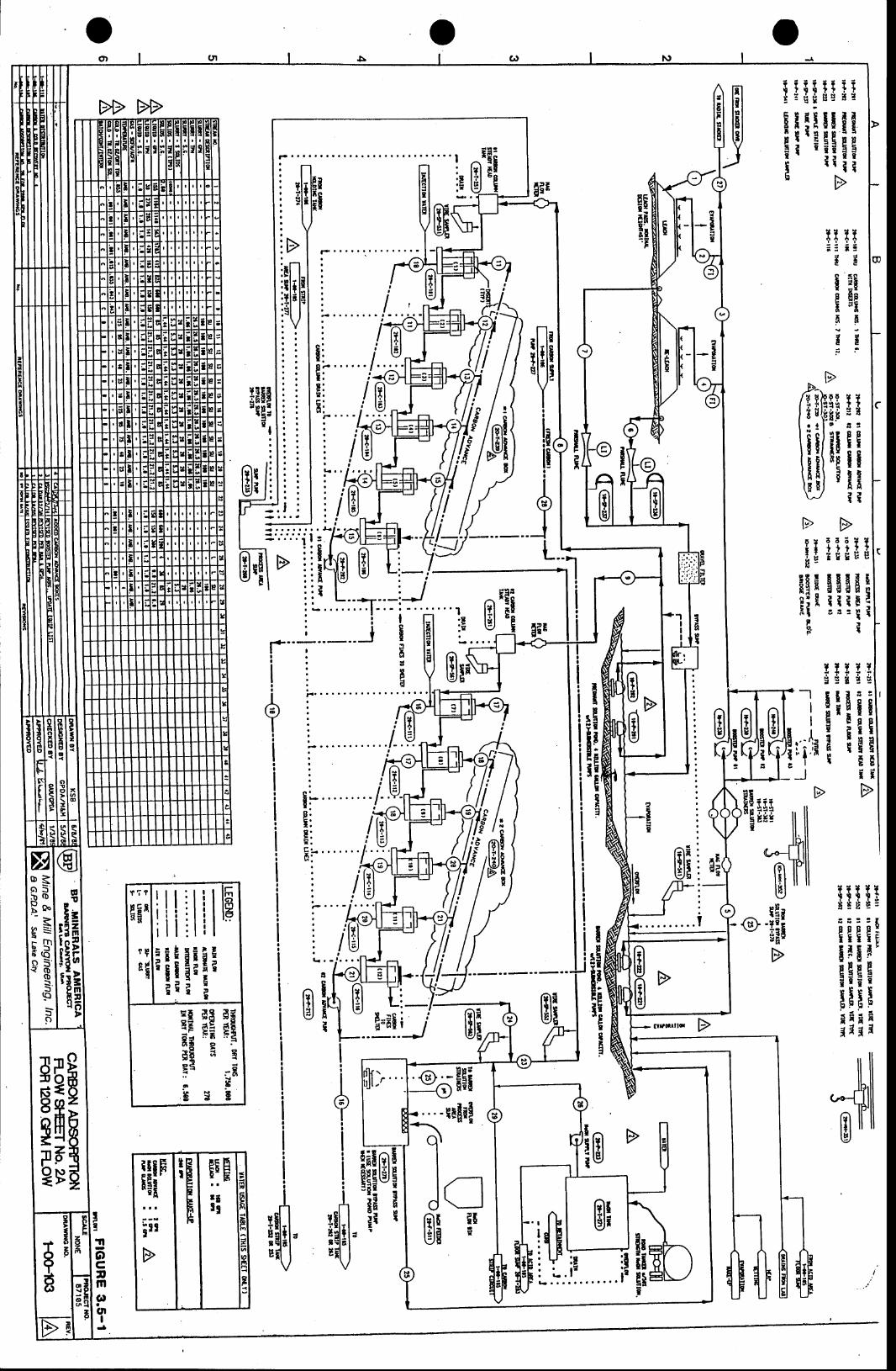
og)
t i lEi i i ii : t * r s31
Elrlltlii I ' : : E II t r I I
gE;
uHil " pr I
B* l=I
gEEHH!.F
I
:l
,
I
6 6 6 T ?
l leilsgEEil[l t rF:a a : I l
tt
t>? ?I IE q
init ; t; l
F3-
E II9 FTT
EEEET I
II i IT*g$t :
9 F F P :l r r IFI IEi l 'EcE ciiii;*xxr l r i
i lTtIE
! :EPgPtd Ii tt tn . '
t>
IIIIID ! :
i!!!I i lE
l l
$liifiEI t l
ir/Lll
ItI
ITE
IH
#Et'tg:t l
:n - l il i l r f :\9IJ:
? ? t ? lsg{ig
B;
!'iI
rilE 'Ei
giB
' 6
: i t
ra!
Ia!
( 6 )
II!
Ia!
III
I
II!
II!
II
!
II!
Ia!
II
rlEf
tEIIaa
--l
II
... l.r i. ' iJ
HEiii il il
ffrl€ l
-?e rr!il
L:-;!!r
t
BB EiH"
#rI'r
!
!i
I!ir-l
lllil'lni(J ,
EIEBIiir
I3iEfiHEI r"E
t
3a
;$t-!
tr!
E=itF1li
<lf , lo lh
=rnf,
_4.f,ooI .(o-o
ooBD
rFbl
ooq
iFE
:elgia;A;E:= iEbs's
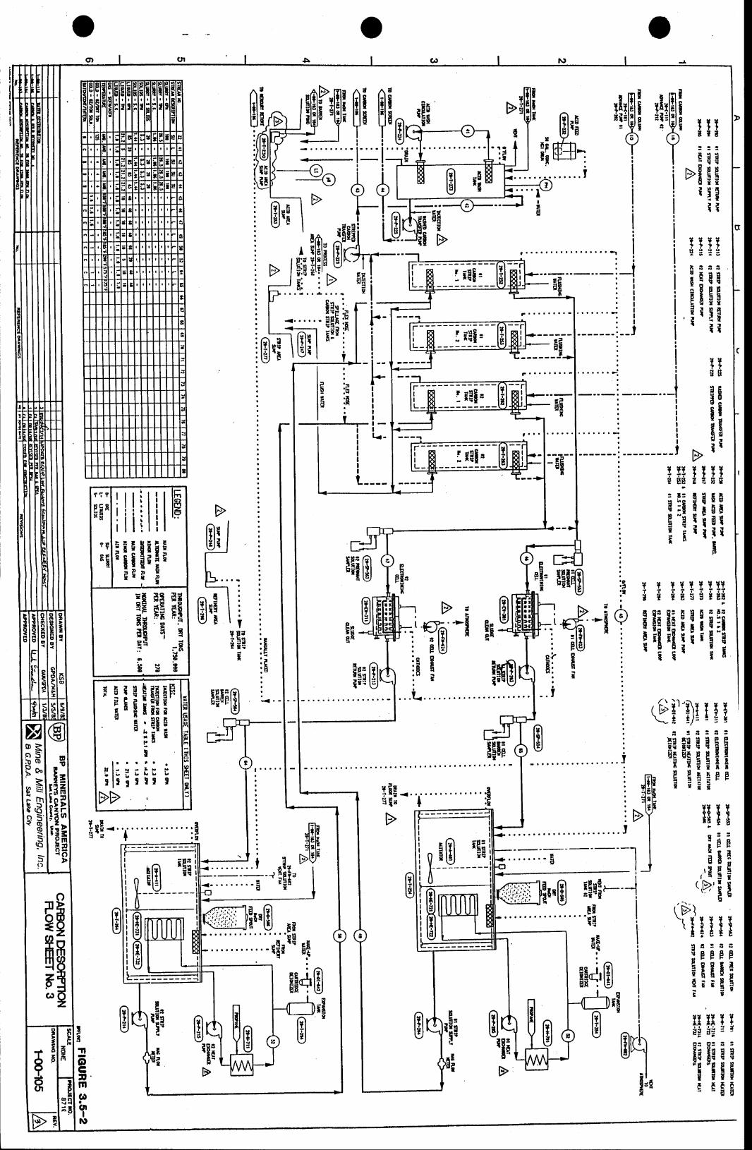
ElIi t3 l
3
Il
iIpT
'!'$iTTTt t t: : :E g g
'EEErl!
t t
3 r ra
EEgH: I I3" l l
T T ? i T I ? T II { { E { g ltg
tEitiiiil,l,ilI I !I
3 ! t : 3 :
EiIAEET i E i T
Erlppe i a
rrHll*g* ; : :
niniiiq IgE
[iI,;ii ffi:
: " I
:r 5 l5E'Bd:. . .L .
1 . . . . . . . . . -
I
d
T T TT
,eEE
--!ilB B
iEE!ig
I I lTa a t s 5
ilgglill
E
J!
t_-rI't!' I,
I
tHu*a :
: !g
;
r'di'\ !
x !l l
EE;
, pl r 5F I
I,iI
:3p5!tfflr
B"*l:E=EEIffiH!E
Itig
:5. t
:I
t o ,YE
:E. F. t r' r
: h
Yp d:3t i
I
E
tTilf ru t8
:EF
,.IEEr,E'i E'ii int
iH*!--.-lI.......-t
'!ll"EIt?ffili"BgFs*:
ffi4'Bdui
n lt ? ll ? l
r3
9 ! : : l 3
:pppp
iE!EEB
BliE
:Fcat
-l.
B
Fit?
Eg9 aFN
B Bqi:'
,
rIIL
r iB '8.[ -
1rr....i
:EigiEsEii:5 .;*- 8'ssE
=EtEilii'' ti;uE
i
!l!ititio 1
I;]!frfrIgB136'HE
slJ I$ lao l
I
s(o5ooI -5If,()
ooIp
ErD-o
o
rla
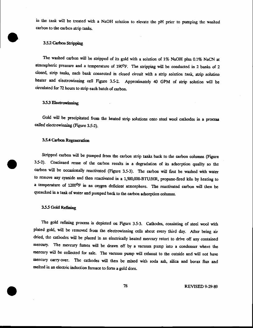
in the tank will be treated with a NaoH solution to elevate the pH prior to pumping the washedcarbon to the carbon strip tanks.
352 Carbon Strbping
The washed carbon will be stripped of its gold with a solution of.lVo NaOH plus 0.12o NaCN atatmospheric pressnre and a temperature of 190h. The stripping will be conducted in 2 banks of 2closed, strip tanks, each bank connected in closed circuit with a strip solution tan\ strip solutionheater and electrowinning cell Figure 3.5-2. Approximately 40 GPM of strip solution will becirculated for 72 hours to strip each batch of carbon.
3-53EteCrwinning
Gold will be precipitated from the heated strip solutions onto steel wool cathodes in a procasscalled electrowindng (Ftgute 3S-Z).
35.4 CarbonRqencratim
Stripped carbon will be pumped from the carbon strip tenks back to the carbon gslurnns (F gute3S-2), Continued reuse of the carbon results in a degradation of its adsorption quality so thecarbon will be occasionally reactivated (F gure 35-3). The carbon will first be washed with waterto remove any cyanide and then reactivated in a 1,500,00GBTUIHR, propane-fired kjlo by heating toa temPerature of 1200oF in an oxygen deficient atmosphere. The reactivated carbon will then bequenched i161ank of water and pumped bac& to the carbon adsorption sslrrmns.
355 GoldRefining
The gold refining Process is depicted on Figure 3.5-3. Cathodes, consisting of steel wool withplated gold, will be removed from the electrowinning cclls about every third day. After being airdried, the cathodes will be placed in an electrically heated mercury retort to drive off any containedmercury' The mercury fumes will be drawn off by a vacuum pump into a condenser where theaercury will be collected for sale. The nacu,- pump will exhaust to the outside and will not havemercury c'arry-over. The cathodes will then be mixed with soda as\ silica and borax flux andmelted in an electric induction furnace to form a gold dore.
78 REVISED 9-29-89
f;rp l,,
I!
!
I
*t$l'ryigiE;
T ? I991E ! !
:!E0!aii
i l$E $ 9
IEHniiEEg: nI!i
EJ
EB!IE
iEIiEt
EIUr i l d
l;iisg
t
+EI
B
- t *f;'u
Gt
\mffi ril
t#iilt!1
B@lqg TTTTT; i E S E
BEe@,;E
itBil
p*;l
J
1 T 1T T 111 t d E ! i - E
I E Ig f; EElgH;i!:
.ll
oCtmC!t?J|I
(t
e6i- 'Effiu *i'ii ' .s-|[*E'gql E
B]tr E[iF
iz6
titEtfr
I i ,H i t
- q l
U T,:E
!,.*c's
ilI!E!IEF
$fiFE
€
=l3 =< F
dt* *;gi
'u
I
f r ?
HFf p
sH
IIEI!EF; ; i i l E5:q l r"'3ll
Igr il r r r r t r
l l : - - - i -!Ftr iJ i
<lrlool
I
<lrn(oJoof,sf,.o
ooTtrb
Er$o
I- D3mgo
o
8B=r
ffigiB
rilgf i i t t '. H
r t l 3!9 t r
-lt
KltE!I
6:tI
Br!
3.6 ArcillaryFacilities
Aocillary or support facilities for the Barneys Canyon Project will consirt of an analyticallaboratory, a truck shop and warehouse, erplosives storage, fuel storage facilities, parking areas, and3i lrlminisf;ation building. The locations of most of these facilities are shown on Plate III. Thetotal laboratory facility will include a sample preparation room with drying and cnrshing equipment,wet chemistry laboratory fire-assay laboratory, a metallurgical testi.g laboratory and an atomicadsorption analytical room. The truck shop will be used to service and maintain all mining
eqrripment. The warehouse will be used for storage of parts and equipment for the shop. The fuelstorage facilities will be sited as appropriate for efficient operations. Fuel spill control Eeasuresissluding safety berms will be installed at each fuel storage site. A Spill prevention Control andCountermeasures Plan (SPCC) has been prepared and implemented as required by Federal law. Theadministlstiea luilding will house offrces for management personnel. Parking lots for employees willbe located at the xdminis6sfiea [uilding. Parking for company-owned eqrripment and man-carryingrahicles will be provided adjacent to the truck shop, process luilrling 6sd sdninistration building.
3.7 WasteDftpcal
Waste materials generated by the activities at the Barneys Canyon Project will consist of minewaste rock, spent ore on the leach pads, and trash. Mine waste rock will be disposed in the wastedumps, as described in Section 3.2. Spent ore will be reclaimed in place. Trash will be hauled to anearby, permitted municipal laDdfill. Waste solutions from the labs and process buildings will behandled in the process s)4stem in accordance with BWPC permits.
3.8 ProductionscLeduls
Waste rock removal began in the Barneys Canyon pit in the first quarter of 1989 and in theMel-Co pit in late 1989. Nearly J milliea tons of ore and waste will fs minsd from Barnep Canyonin 1989 and about QJ rnilliql tons of waste will be pre-stripped frorn Mel-Co in 1989. Barneyscanyon and Mel-co pits will be mined concurrently in 19g9 and 1990, by which rime ths fust phaseof Mel-Co will be minsd 6ut. Barneys Canyon operations will continue, exclusively through 1991,l9{2, and 7ryB. Beginning in 1994, pre-stripping for the second phase of the Mel-Co pit willoourmerce and Barneys Canyon and Mel-Co pits will !e minsd concurrently thtough 1994, 1995, and1996.
80 REVISED 9-29.89
The Barneys Canyon ming will operate two 12-hour shifts per day,7 days per wee\ 52 weeksper year. Because of limitations imposed by severe weather conditions, Mel-Co operations may becurtailed during the worst winter montbs; however, if conditions pernit, mining will proceed Zhours per day and 52 weeks per yqr. tfte 665hing plant and pro@ss plant are scheduled tooperate Z hours per day and up to 365 days per year. The laboratory and tnrck shop will beoperated year-round in support ofboth ths mining and process operations.
39 TopsoilUanagenent
Available topsoil naterials at the Barneys Canyon mining site will be stripped with dozers andscrapers placed in storage piles on sites protected from excessive surface runoff. Plannecl topsoilstockpile sites are shown on Plate III. The topsoil portion of &e soil profile, gsnsisting, onaverage' of the upper 12 inches, will be salvaged. In areas underlain by Copperton soils no morethan ftg upper 12 inches of topsoil will be salvaged. The Soil Conservation Servicc has determinedthat these soils are less thap ideal for use as topsoil. Facility sites having Copperton soils includeall the leach pads, the solution pon&, process building; substation, lclminisftnties building, srushingand screening are4 the eastern 3.8 acres of the shop building area, and the eastern L6 aqe,s of theore stockpile area. All other facilities are covered with Harkers-Dry Creek associatioq Dry Creek-Copperton association or Bradwhaw-Agassiz association soils which the SCS recognizes as suitable foruse as topsoil. For these soil tlpes, borrow deptbs may exceed 12 inches to meet topsoil yslrrmsneeds, if necessary.
Recoverable soil vol'-es for eac.h @mponent of the project are s'mmarized in Table 3.9-1. Inthe event that areas currently identified for topsoil salvage are found during reoovery operations tolack the 12 inches of topsoil ne@ssary, the balance of the soil necessary to carry out the topsoilredistribution plan desoibed in Section 5.4 will !s meinlained by borrowing additional soils fromother areas having greater tha! 12 inches ofsoil.
In the Mel-Co atea, total available toposoil e:rceeds the anticipated topsoil demand forrecl'-ation by approximately 28,000 cubic yards, as described in Table 3.9-1 and section 5.4.Becaue of the steep terrain and resultant difEculties in removing andl trenRporing the materia!only a sufficient volumE of toposoil to accomplish the plar,r,ed reclamation worh will be recoveredand stockpiled from the pit and dunp sites.
81 REVISED 9-29-89
The topsoil recovery plan wil include nixing the e:risti.g vegetation into the soils which will
provide additional organic matter to the salvaged soils. The topsoil storage piles will be protected
from wind erosion and slope drainage by seeding with 6 lbs per acre of annual rye to protect the
surface with a quick growing vegetative cover. In additio4 Kennecott will apply the permanent
reclamation seed mix to those topsoil stockpiles or parts of topsoil stockpiles which will not receive
future contributions of topsoil. Stockpile surfaces that will receive additional topsoil as part of
ongoing mins gxpanslon will be vegetated with the interim seed mir
82 REVISED 9-29-89
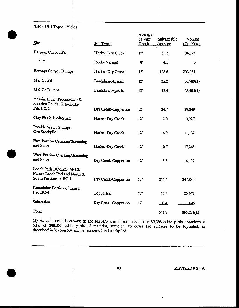
Table 3.9-1 Topsoil Yields
Site
"T": canyon Pit
Barneys Canyon Dumps
Mel-Co Pit
Mel-Co Dumps
Admin. Bldg., Process/Lab &Solution Ponds, GraveVClayPits 1& 2
ClayPits2&Alternate
Potable Water Storage,Ore Stockpile
East Portion Crushing/Screeningand Shop
Pad BC-4
Substation
Total
Soil TVoes
Harker-Dry Creek
Rocky Variant
Harker-Dry Creek
Bradshaw-Agassis
Bradsha*Agassis
Dry Crcc&€opperton
Harkcr-Dry Creek
Harker-Dry Creek
Harker-Dry Creek
AverageSalvage SalvageableDepth ,Acreaee
11 523
0n 4.1
125.6
35.2
42.4
24.7
2.0
6.9
r0.7
Vohrme(Cu. Yds.)
u3n
0
?n46F.s
56,789(1)
68,,105(1)
t2n
IT
L2'
LT
t7
West Portion Crushing/Sg1'ssningand Shop Dry Creek-Copperton 12n g.g
I*ach Pads BC-1,2,3; M-l,2;Future l-each Pad and North &South Portions of BC-4 Dry Creek-Copperton l2n 215.6
f,s6aining Portion of l*ach
39,U9
3,m
Ll,l32
17,?63
14,197
y7,835
m,167
g5
866,521(1)
Copperton LT 725
Dry Creek-Copperton 72' 0.4
54L.2
(1) Actual topsoil borrowed in the Met-Co area is estimated to be 97,353 cubic yards; therefore, atotal of 100,000 cubic yards of material, sufficient to cover the surfaces to be topsoiled,-asdescribed in Section 5.4, will be recovered and stockpiled.
83 REVISED 9.N-89
3.10 OrerbudcnDispoal
Salvaged topsoil will be stockpiled and managed in the manner described above in Section 3.9.
All other overburden will be hauled to the mine ch,mps shown on plate trI and dumped.
The dumps will be constructed with top surfaces sloprng gently back toward the natural hitlsidss
for the purpose of drainage control. Dudng rnining, the dump outslopes will have a slope nngls 6f
approximately 37 degrees. The waste will be spd-drrmped from the haul trucks and dozers will be
used to push the waste over the dump outslopes as Decessary. The geologl of the overburdEn is
described in Section 2.1. The chemical characteristics of the orrerburden material regardi'g the
potential for toxicity, are discussed below in Section 3.11.
Dump slope stability analyses have been performed by Sergent, Hauskins & Bechpith for the the
large Mel-Cs drrmp and the Barnep Canyon 6300 and 6JQQ rnine dumps. Analpes were performed in
those parts of the planned dumps where the most critical natural slope conditions were encountered.
The plarrngd drrmP configurations for this project, includi'g placement of the dump material at the
angle of rePose (37 dogrees) were used in the calculations. Stability analpes performed for the
proposed dumps resulted in the following r:rnges of factors of safety (F.S.) under static conditions:
Barnep Canyon Dumps
Mel-Co dump
A safety factor of 1.0 or nore indicates that a slope is stable; therefore, the Barneys Canyon and
Mel-Co dumps are predicted to be stable.
Sergent Hauskins and Beckwith also conducted dynamic stability analyses for the clt,-ps. These
calculations indicate that "...permanent defornations under horizontal accelerations of .2 to 3 g for
F.S. : 1.05 to 133
F.S. = 1.1to 1.4
84 REVTSED 9-29-89
the critical failure zones would be less than 2 feet."(Sergent Hsrrskins and Beckwith, 1983) Further
details can be found in &s drrmp stability analpis report which has been separately submitted.
3.11 Evaluation of lvlafcrials Tuicity
In order to respond to the Division's rule regarding identification 6a61 [gndling of toxic
materials, analyses of waste rod ore, and leached ore were performed lsing ono or more analytical
techniques that are accepted means of determining toxicity of waste materials that are either
naturally occurring or have been disposed in the natural environment. Waste rock was analped for
total content of seleded metals, weak-acid-soluble metals @P toxicity test), and acid-base potential.
Raw ore was analped for total metals. Spent leach material Qeached ore) was analyznd for total
metals and EP toxic metals.
85 REVISED 9.29-89

This page is intentionally lsft Uank.
REVISED 9.29-89
Thc EP toxicity tcst involvcs a 2d-hour leach of solid matcrial in a solution of acctic acid with
a pH of 55. Thc ratio of lcachate to sample is 20:1. The EP toxicity rcst was designed to simulate
rcatly acid conditions that can cxist in landfiX envirouments, and under which mrny tDetsls may bc
dissoh'ed aad mobilizcd Thc EP toxicity tcsr was sclcacd bccaue it is aa acccptcd US. EpA
tldytical protocol and is a worst c'<c tcst for minc-relatcd material. lv{iaing of the Mcl-Co dcposit
will rcsult in thc disposal at tbe rning duap of a small aDrount of pyritic wastc rock in comparison
to tbc total wastc volune. It is important to point out thx1 mining wastes arc curreutty cxemptcd
by Fcderal ald Statc law from rcgulatioa undcr tbc laws and rcgulations that established thc Ep
toxicity tcsts and for which EP toxicity o'aj),ses have rcgulatory impact.
Thc acid-base potential test was dcveloped for craluation of coal mine wastcs. Each sanple is
aaalpcd for acid-gcasr3ting potential aad neutralization potcutial. Acid-geacrating potential is
based oa the total sutfur coatcut of the sample. Ncu6alizalien potcntial is bascd priacipally upon
the carbonate content of tbc sampte; howcvcr, tbe affcct of tbe ioo-cxchange capacity of clap are
also t"kcn into account. Thc rcsults of acid-gcncpring and neutralization tests arc catculated in
tons of Ca@g per 1000 tons of material. In the case of acid potenti4 thc result is e,:rpresscd as a
ucgative number cquivalcnt to thc toDs of CaCO3 required to Ecutralize the amount of acid
gencrated. Neugrli'ation poteutial is exprcsscd as tbe tons of CaCO3-cquivalcnt matcrial pcr 1000
tons of waste. The results of cach separate test are thcn added together. A positivc rcsult
indicates that the samplc i5 ssu6ali'ing, a acgativc aumber indicatcs that it is potcntialty acid
Eencrating. This rcsult is rscd to dcterminc the amouil ef sgutreli#ng material (soil or overburdeu
with neutraliri"g potentiat or additivcs like agricultural line) Dcccssary to neutralizc acid-generari',g
waste.
o gl REVTSED ?-20-88
Acid basc potcutial analpcs for one Barncp Canyon rcprcscntatiw waste rock compositc sanple
and nro Mcl-C-o rcPrcscDtatirc composite waste rock samples yiclded the fotlowing rcsults:
Samole
Baraep Canyon (BC-85,
compositc)
Mcl-Co (MC-25, f, to
255'compositc)
Mcl-Co (MC-25,3?5'
to 570' composite)
lEt
8.9
8.6
63 .f T/10007
4Tl10007
Acid-Basc Potential
+556 T/10007
Thc full laboratory rcPort is arailable in Appcndix C-Itr. Thc anatytical laboratory has determincd
that the Mcl-Co saoplcs are ooly slightly acid-forning aad thcrcforc aon-toxic. Tbis is due to the
rclativcly low pyrite coateut of the orc and waste samplcs. Thc samplcs selcctcd for analysis rrcre
from &ill holes coataining botb oxide and snlfidc oatcriats and wcre sclcctcd as rcprcscntativc of
zones of mixed ore and wastc that wiU bc eacountcrcd drrring mining of tbc orc body. Most of thc
ore body 6ssfainc only oxide orc and waste. The cstimated total quantity of sulfide-bearing ore and
waste in tbe Mcl'Co pit is 65,000 tons; the snlfids orc fractioo is estimatcd at approximatcly
300,000 tons. Total wastc for Mcl-Co is 14,000,000 toas; thcrcfore, tle total sulfide-bcaring material
comprises only 45 Perccnt of the 1e1st rrring wastc to be rcmowd from the Mel-Co pit. The mine
dumps wi[' thc!' contair a like proportioa of s,rrlfidg waste. Therefore, tbc dumps will not gcncrate
acid solutioDs as a rcsult of pcrcolaring rain watcr. The abscucc of low pH waters in the duops
will grcatly rcducc the potential for rlisolution and melilizalisa of most potcntieny toxic metals,
sincc these metals arc solublc at low pH's.
Thc only signifigaa1 srrlfidg mineral prcsent in the ore and waste at Barnep Canyou is pyrire.
88 REVISED 7-20-88
to
Pyrite in qrranliligs 5rrffisigs1 to gercrate sipificaar acid will be rcadily ideatifiabte by visual
DcaDs' In additioA as patt of gold assaying fel rning ore gradc coutro! 1f,e rnin6 aralyticat
laboratory will dctcrmine aot oaly gold content but also cficther or lot the orc aad adjaccat rods
arc sulfide beatilg or oxidized. Tbc laboratory aaalpis wiu bc pcrforocd on dccly spaccd btast
holcs' ff,s rning gcotogist or othcr pcrson rcsponsible for orc gradc coatrot in thc pit will bc
responsiblc for dclincating aad marking tbc pyritic waste rock in thc pit througbour the life of tbe
niae. Dudlg ovcrburden remora! ppite-bcariry waste will bc identificd botb from the blast hole
alalyttcal rcsuls aad by visual mcals, martced with 0ags and loadcd in separate trucls for hautagc
to the wastc dump cfierc it wi[ bc dumped such that aoa-sulfitic wastc cal hter corer it. If
Dcccssary at thc cnd of iaslath6ss of a dump, nou-sul6tic wastc rcck wi[ bc stoctpilcd oa the top
of the dump for usc as 6nal cover material for sulfidc-bearing roc,k. Thc thickness o; sss-snr6dc.
bcaring waste rock coracr will bc ao less rhan t\ps fssl
The Mcl-Co ore body s6arain< idcatificd zones of sulfidi ninglalizatios as shown oD cross
Scctions A-I'3 - 5 which are includcd Appcndix A-I, the Confidentiat Appcndir Somc of the
sulfide'bcaring material oocurs in isolatcd and incgular pods wirhin in rhe niddle aad uppcr parts of
thc ore body. The reviscd rnining plan for the Mel-Co deposit has rcsulted in a larger pit tha', had
originally bceu coutcnplatcd. As a result, a discretc sulfidc zoue at the base of tbe orc body and
acar tbe pit bonom wiU bc rcnovcd. Thc sulfide-bcaring waste in the uppcr portioos of thc pit
*ill' by virtuc of ia irrcgutarity, be nixcd with non-sutfitic waste duriDg ovcrburdcn rcmoral aad
d-pto$ &erefore, Do conceDtratioos of sulfide waste will be deposited in thc druep from thesc
zoles. The sulfidc-bcarit€ rock at the basc of the orc body, though sesleining gold rnineratiuatien,
docs not lcnd itsclf to bcap t6ching and will not be rnins4t with tbc oxide orc. It is cnrrcntly
trGnnecott's intcation ts ming the ore fraction of rhi< material and haul it to its Magna smelter
rvtcrc, bccause of its high silica contcnt, it wiU be rscd as flu and the sentrins4t gold will bc
recowred. The uscftrloess of rhiq sulfids ore as a 0ux caDnot be dctcrnincd rrntil gs rnining
89 REVISED 7-2&88
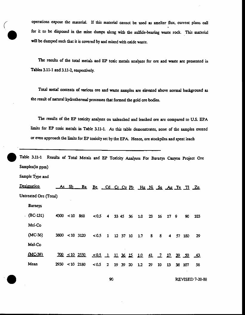
oPcrations cryosc the matcrial. If this matcrial carnot bc uscd as sneltcr llu:g current plans call
for it to be disposcd in thc .ios drnnps along with tbe sulfidc-bcaring wastc rock This material
wiu be duped such tbat it is covcrcd by aad mixcd with oxide waste.
lbc rcsuls of the total mctals aad EP toxic mctals aaalpx for orc and waste are prcscntcd in
Tablcs 3.11-1 and 3.L1-\ rcspectivcly.
Total metal conteats of variors orc and wastc samplcs arc clewcd above aormal background as
thc rcsult of aatual bydrotbcrmal proc*scs that formed the gold ore bodies.
The results of &e EP toxicity aaalyses on unlcached and le,ached orc are compared to US. EPA
limi6 fs1 EP toxic mctals in Table 3.11-1. As this table demonstrates, DoDe of the saraplcs cxcced
or cvc! approach t[s li'nits for EP toxicity sct by the EPA. Hcacc, ore stockpiles aad spent lcach
Baracp
. (BGal)
Mel-Co
o{c-36)
Mcl-Co
fMc-38)
Mcan
u.4L 7g
L2n10 l : }
1
2
90
3g _s. -s-3{t rm 58
REVISED 7-20.88
I f"Ufe 3.11'1 Rcsults of Total Mctals and EP Toxicity Analyses For Baraep Canpa Project Orc
Samples(ia ppn)
Sanplc Tlpe and
Dcsiqpation As Sb Ba @ Cd Cr Ctr Ib. He Ni _S9. ls, _&. n A
Untrcatcd Ore (Iotal)
4300 <10 860 <05 4 33 45 % 1.0 A 16 fl 9 90 103
3800 <10 3120 <05 t L2 37 10 1.7 4 57 180
aq <10 2550 <05
Dn <10 2180 <05
11 tE t5
1939m
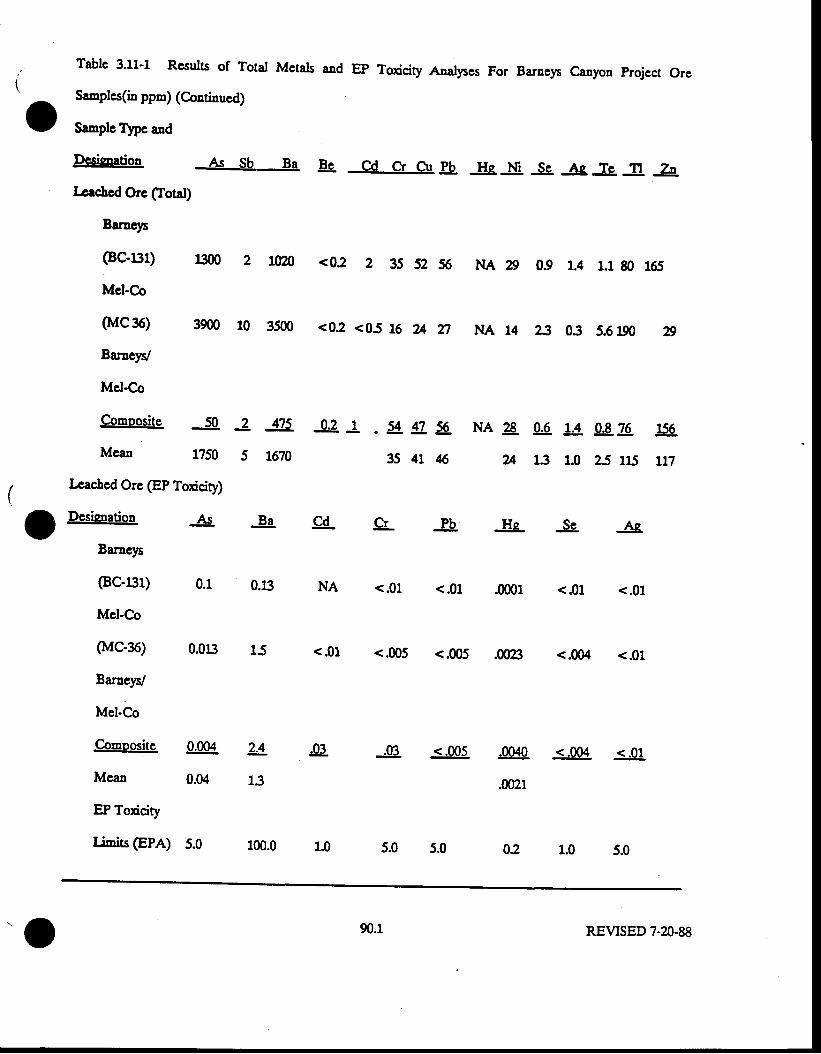
Tabls 3'11-1 Rcsults of Total Mctats aad EP Toxicity Analpes For Barncp caayon project ore
Sanples(in ppn) (Coatinucd)
Sample Tlpe and
Dcsinoation As Sb Ba & Cd Cr Or !L He _l$. Se Aq _I9. Jt Zn
Irrchcd Ore (fotal)
Baracys
(Bc-[}1)
Mcl-Co
0{ca6)
EaracyV
Mel-Co
uno 2 LAm <02 2 35 52 56 NA 29 0.9 r.4 r.1 80 165
3900 10 3500 <02 <05 16 U n NA 14 23 03 5.6190 A
C-omoosite 50
Mean 1250
I-cacled Orc (EP Toxicity)
!58
tt7
2
5
os _q?. _L . 5{. tZ 50. NA 28 gg. !t gg.?0.
t670 35 41 $ U 13 1.0 2j u5
g{ PbSL Hs -Ss. AcI
Desienation
Ba-elr
(Bc-a1)
Mcl-Co
(l"tC-36)
BarneyV
Mel-Co
Comoosite
Mcan
EP Toxicity
Iimis (EPA)
As -&
0.t:}
0.01:}
0.m4
0.04
<.01 <.005
<.01 <.01 <.01 <.01
<.005 .0@ <.m4 <.01
2-4 J3.
13
-!9. <.005 .0040 <.004 <.01
.m2t
5.0 5.01.0
90.1
02
REVTSED 7-20-88
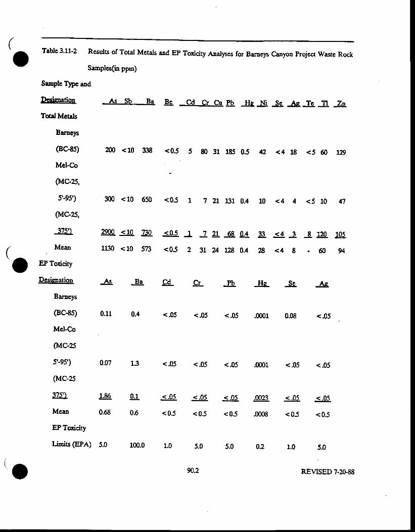
to
Table 3'11'2 Rcsults of Total Metals and EP Toxicity Aaalyses for Baraeys Canyon projcct wastc Rock
ga,nplcs(in ppm)
Sanple Tlpc aad
Dcsiaation As Sb Ba & Cd Cr Crr !h Hs _!g. lg As _&. _g _Zg
Total Mctals
Barnep
(BC{s) m <10 338 <05 5 80 31 185 05 42 <4 18 <5 60 :f2s
Mcl-Co
(l*lC-2S,
t'95) 300 <10 650 <05 t 7 21 ljll 0.4 10 <4 4 <5 10 47
(l"tC-25,
37s') 2e00 <10 Eg <0.s J J 2r _gg. gL 33. <4 3 3 J2q $5.Mean n30 <10 ST3 <0-5 Z 3t U t2g 0.4 ZB <4 g - 60 94
EP Toxicity
Desienation
Baraeys
(Bc-8t
Mcl-Co
(MC-25
t-95')
(lvlC-25
375')
Mcan
EP Toxicity
I inrils (EPA)
<.05 <.05 <.05
1.0 5.0
REVISED 7-20-88
As -&.
0.11 0.4 <.05 <.05 <.05 .0001
gL -Se.is-lb. Ascd
130.07
0.08 <.05
.0001 <.05 <.05
1.86
0.68
<.05
<05
<.05
<05
<.05
<05
.0023
.m08
0.1
0.6
<.05 <.05
<05 <0.5
5.05.0 100.0 1.0
90.2
5.0 02
I'o
I'o
Eaterials in the heaps arc rrot aaticipated to provide a sourcc of soluble Drctals to the cnviroDgrent.
Tbc rcsults of EP toxicity analyscs on Barneys Canyon and Mel-Co wastc rod aloqg with EpA Ep
todcity limits arc prcscnted ia Table 3.11-2. As in the case of thc orc sanples, thc rcsults of tbese
tlsllscs indicate Do gn'ntitics of solublc metals iu cxccss of tbc EPA statdards for thc EP toxicity
proedurc. In additioD, sincc, as tbc acid-base poteutial analpcs indicate, tbe waste rock dumps will
Dot substsltidly lower the pH of water pcrcolating througb thcn, the pH 55 conditions sinnlatcd in thc
EP todcity tcst should not be approached 8t the sitc. Ttcrcforc, evcn the lcrc,ls of metals rcportcd out
of tbe EP toxicity tcsts Eay lot be reached in watcrs percolaring throryb gg rnins dpnps.
90.3 REVTSED 7-20-88
3J2 Runofi and Sedimcnt Control
3 lt 1 R1ngffVotumes Fcrirrreres
Runoff volumes and peak flows in and around the project area wEre calculated usi"g the SoilConservation Service (SCS) Curve frf'mles technigue, utilizing a conputer program developed byHawkins aad Marshall (1980). Precipitation depths for the 10-year, 2S-year and 100-year, 2ahourrainfall events were used in the calculations to determine the nrnoff peals and volumes for eachevenl The precipitation depths were obtained from the National Oceanic and AtmosphericAdministration Precipitation Frequency Atlas for Utah (LgR). The precipitation depths for theseevents were found to be 2.7 inches, 3.0 inchcs, and 3.7 incheg respectively. Runoff pcaks weregenerated usi4g the SCS $pe II rainfall distribution which is gpical for the westerD United States.
The curve numbers used in these calculations were based on local soil hydrologic characteristicsand vegetation tlpes. Soils were grouped according to infiltration c,haracteristics, hydrologic soilgroup A having &s highest infiltration rates and group D having the lowest infiltration rates.Thcre are two main f,ydlstogic soil groups in the project area. Soils of group C are found largelyin the valley alluvium and colluvium beneath tbe Barnep Canyon project area. Soils of hydrologicgroup B are predominantly found in the higher elevations. The vegetation gpes are largelysage/grass co--unig in the lower elevations and gambel oaks on the low elevation north faorgslopes and in tls highel elevations. Based on this and other information e[tainsd over one year ofwork at the site, the base curve numbers bave been revised to better re0ect actual runoffconditions at the project site.
Vegetation tlpe
Sagebrush (fair)
Oak/Aspen (fair)
Source: Van Havern, 1986
Soil Group B
CN=48
CN=47
Soil Group C
CN=65
CN=64
since each watershed tiss within a predominant soil t1pe, the curve numbers were weightedaccordiqg to the a.Eount of area containing oak forest and sagebrush in each drainage basin. Acurve number of g9 was used for calculating runoff yslrrmss and peaks fron the compacted wastedumps surfaces. A high curve number was intentionally selected to provide a conserrrative ssrimxteof runoff from waste dumps; the actual nrnoff would be cxpected to be less than that predicted.The assumptions used in these calcurations may be found in Table 3.12-1belo$,.
9r REVISED 9.D.89
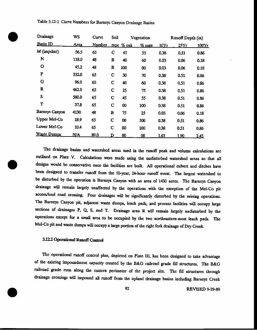
Table 3.12-1 Curve Numbers for Barneys Canyou Drainage lasins
Drainage WS Curve Soil Vegetation RunoffDepth (in)Basin ID Area Number nnre 7o oak d saee 10yr afyr 100yrM (inpdnt)
N
oP
oR
sT
Baruep Canyon
Upper Mel-Co
Iower Mel-Co
565 65
118.0 ,18
452 ,18
33L0 65
96.0 65
462.0 65
580.0 65
37.8 65
4130 ,18
18.9 65
10.4 65
c45
Bq
Blm
c30
C ,10
c25
c45
c00
B75
c00
5sffi
00
70
60
75
55
100
E
100
100
038
0.03
0.(B
038
038
038
038
038
0.(B
038
038
051
0.06
0.06
051
051
051
051
051
0.06
051
051
0.86
0.18
0.18
0.86
0.86
0.86
0.86
0.86
0.18
0.86
036
The drainage basins and watershed areas used in the runoff peak and volume calculations areoutlined on plate V. Calculations were made 's,i'g the undisnrbed watershed areas so that alldesign" would be consenrative once the facilities are built. All operational culvert and ditches bavebeen designed [6 [rancfsl runoff from the 10-year, 2ahour runoff event. The largest watershed tobe disturbed by the operation is Barneys Canyon with an area of 1430 acres. The Barneys Canyondrainage will remain targely unaffestsd by the operations with the exception of the Mel-Co pitaccess&aul road crossing. Four drainages will be sipificantly disturbed by the rnining operations.The Barneys Canyon pit, adjacent waste dumps, leach pads, and process facilities will occupy largesections of drainages P, Q, s, and T. pleinage area R will remain largely undisturbed by theoperations cxcept for a snall area to be occupied by the two northeastern-most leach pads. TheMel-Co pit and waste dumps will occupy a large portion of the right fork drainage of Dry Creek.
3J22 Operational Runotr Control
The operational runoff control plan" depicted on Plate m, has been designed to take advantageof the existing impoun'lment capacity created by the B&G railroad grade fill structures. The B&Grailroad grade nrns along the eastern perimeter of the project site. The fill structures throughdrainage crossings will impound all runoff &om the upland drainage basins ia4lu.ring Barneys Creek
y2 REVISED 9.29.89
(Plate III). Approximately 60 years ago when the railroad was constructd culverts were placed in
the stream channel at thE bottom of the railroad 6ll to allow runoff water to 0ow through this
s6lanlrmslt. Since that ti-e, these culwrts haw become partially or completely 6lled with
scdiments rendering them ineffective and carsing ths qaganlcment to act as an impounding structure.
In 1985, eacb impoundment was 6tted with a spillway culvert approximately !5 feet bclow the grade
elevation in each drainage to permit impounded water to drain through the impoundm:nt without the
likelihood of overflow. The spillway culverts were designed to pass the SGyear flood event or
larger and were placed high enough in the sp[ankrngsts to provide significant storege capacities
below the spillways. All spillway culverts arc A inches or greater in diameter to meet rninimal
design criteria by the Utah State Fngineu. These spillway culverts are in place and the calculated
capacity of each impoundment is based on the invert elevation of the these spillway culverts. Water
is not routinely impounded behind these structures. A diagram illustrating the placement of theseculverts may be found in Appendix D-I. The stage/capacity curves for all impoundmeng located inthe project area rnay be found in Appendix D-I. The nrnoff volunes from the watersheds upgradient
of these inpoundments were calculated using undisturbed acreages. Usi"g this technique, the nrnoffvolumes calculated should be in excess of the actual runoff volumes after all facilities areconstructed, because precipitation faling on active leach pads will be directed to the solution pondsand inactive, ore-covered pads will have substantial moisture retention capacity.
Most haul roads have been designed to allow water runoff from both road surfaces and theupgradient watersheds to Eove along or beneath them with minimal impacts from erosion (Plate m;.the 6ll material from the landbridge haul roads southeast of waste dumps 6400 and 6500 will createthree temporary i"'poundments which will latcr be filled with dump materials. Culverts will not beinstaled in the road fill matcrials that create these temporary impoundments. The roads wi[ besloped away from the road fill slope so all precipitation water falling on the road surface wil draintoward roadside ditches. Roadside ditchEs will run the length of the haul roads througb the projectarea and will be placed along the roadside cut slope to collect all runoff from the watershedsupgradient before the water floun onto the road surface. The roadside ditches will be triangular inshape and x rninirnrrm of 1.75 feet deep. The ditches will have a 2h:1v sideslope from the roadsurface and th:1v from the cut slope. These ditches will be placed at the sane gradient as theroad" Many of the haul roads will be excavated into the bedrock adding stability to these ditchesduring high nureff events. AII roadside ditches will drain to corrryated metal pipe culverts totransfer the water below the road and into impoundments or natural stream channels below (plate
m).
93 REVISED 9-29-89
Comrgated metal pipe culverts will divert runoff water beneath the road at selected 6sssings.These cuhrerts have been desiped to pass runoff from the lo-year, 2A-hour runoff event. Theculverts will be placed along the natural channel gradient [s minirni'c erosion. Desigp specificationsfor &ese culverts may be found in Appendix D-tr.
During operations, all waste drhps wi[ bo constructed so that the dump surface slopes fron thedump crest toward the natural hillside from which it projects to control nrnoff dowa the outslope ofthe dunp' Safety berms will be placed around the top perimeter of the waste du-ps as needed toprevent runoff flow &om 1tr" drrrnp crest dowo the dump face. ,Ite dpmps will thcn be sloped sothat runoff draiDs toward one @rner of the dump for removal to either a drainage shennet or to animpoundment.
Runoff from the snal drainage area upgradient of the Barnep Canyon pit waste rock dumps andfrom the adjacent waste rock dump surfaces will be diverted fu1e rmpoundment M located upgradientof the lower elevation haul road leading &om the Barneys Canyon pit to the waste dump (plate Itr).Runoff from the undisturbed watershed area upgradient of the haul roads will drain onto theuppermost haul road and will be diverted along a roadside ditch and thtough a culvert forcsafainrnsaf in Impoundment M. Runoff &om dump 6500 will also drain through a cu&,ert forcollection in Impoundmett M. In addition, runoff from the y6ste drrmp 6400, adjacent to theBarnep Canyon pit, will drain into rrnpouadment M. The 1fi)-year, 2ghour runoff volume from thethree waste dumps and the upper watershed witl be 103 acre-feet and will be easily containedsithin the 47 acre-feet capacity of Inpoundment M (Table 3:r.-z). Current Utah DoGM regulationsrequire that the impoundments Bust contain the lGyear, ?*howrunoffvorr,-e.
Before the waste dumps arc builg the haul road to the truck shop will create threcimpoundmeuts in the area to later be occupied by the waste dumps. The impoundment to beoccupied by dump 6400 will have a capacity in excess of 80 acre-feet and will only receive runoff&om the 15 acre sasin i1 which it occupies. This i'npoundment will not receirre runoff from beyondits perimeter. The other two impoundments, designated D'r-p 6500 A for the nefr impoundment tothe north and Dump 6500 B for the north impoundmenf will be used to contain runoff from thewatershed above until the waste dumps are completed. These impoundments are not shown on plateIrI' The capacity ef prrmp 6500 Impoundments A and B will contain the full runoff vol,,me from thelfl)-year, 2#hour runoff event from the upland drainage basins.
94 REVISED 9-29-89
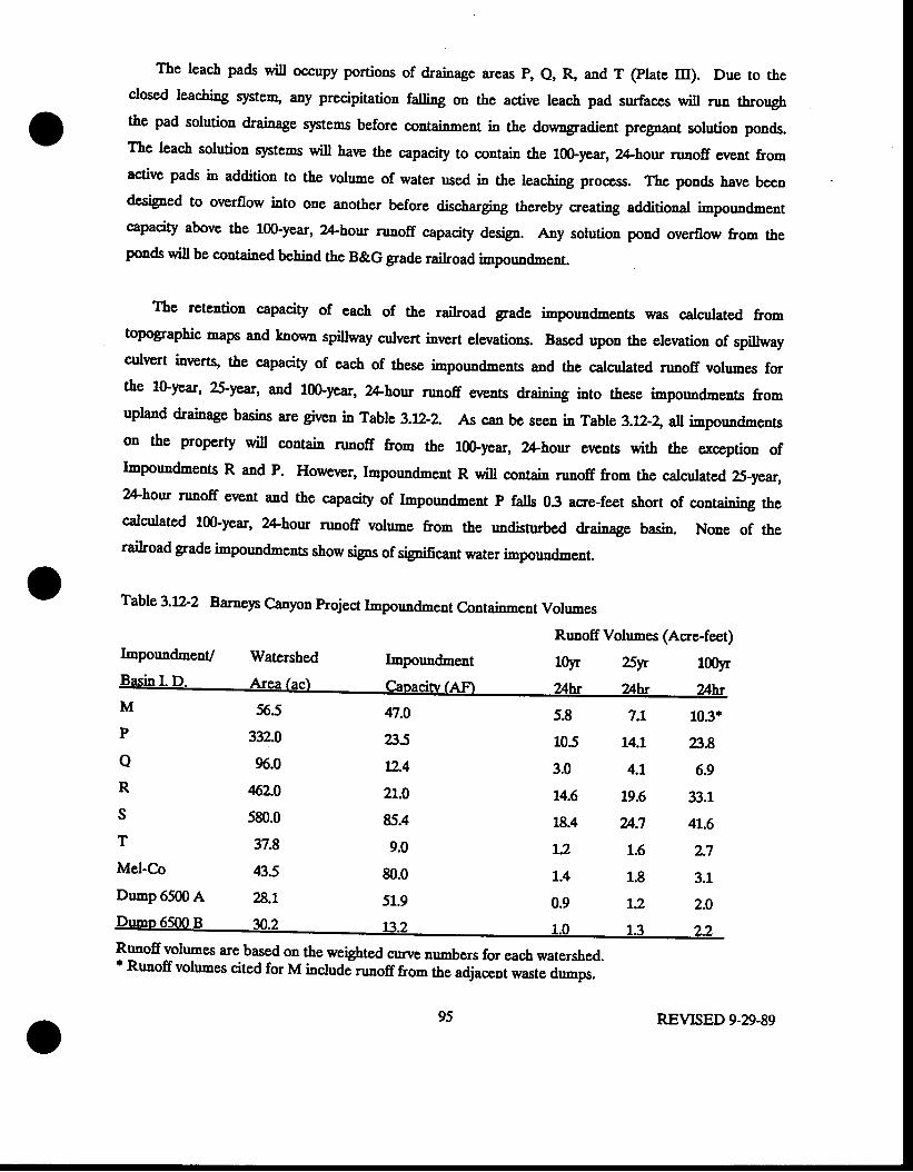
The leach pads will occupy portions of drainage areas P, Q, & and T (Plate m). Due to theclosed leachi'g system, any precipitation falling on the active leach pad surfaces will nrn throughthe pad solution drainage s)Etems before cssfainmss[ in the doumgradient pregnart solution ponds.The leach solution qatems will have the capacity to contain the l0Gyear, 24-hour runoff event &omactive pads in addition to the yslrrrne of water psed in the leaching process. The ponds have beendesiFed to overflow into one another before discharging thereby creating additional irnpoundnentcapacity above the lfl)-year, 24-hour runoff capacity desigD. Any solution pond overflow from thepo'ds will be contained behind the B&G grade railroad impoundment.
The retention capacity of each of the railroad grade impoundments was calculated fromtopqgraphic maps and knocn spillway culvert invert elevations. Based upon the elevation of spillwayculvert inverts, the capacity of each of these irnpoundments and the calculated runoff volumes forthe lGyear, ?S-year, and 100-year, 24-hour runoff evelts draining into these irnpoundments fromuplaad drainage basins are given in Table 3.12-2, As can be seen in Table 3.12-z,all impounrtmentson the proper$ will contain runoff &om the l0G.year, 24-hour events with the exccption ofImpoundments R and P. However, Impoundnent R will contain nrnoff from the calculated 25-year,2ahour runoff event and the capacity of Impoundment P falls 03 acre-feet short o1 sopgrining thecalculated 100-year, 24-hour nrnoff volume from the undisnrbed drainage basin. None of therailroad grade impoundnrents ghgs, sig,ns of significant water impoundment.
Table 3.12-2 Barnep canyon project Impo'ndrnent eelltainmsnt Vorumes
r-poundmenU Watershed Impoundment
Runoff Volumes (Acre-feet)
lqr ?Syr 1005rr
M
P
oR
sT
Mel-Co
Du-p 6500 A
565
332.0
!)6.0
46'2.0
s80.0
37.8
43.5
?3.L
47.0
a5t2.4
2L.0
85.4
9.0
80.0
51.9
5.8
105
3.0
14.6
18.4
L.2
L.4
0.9
7.1
14.1
4.L
19.6
u.71.6
1.8
r.2
103.
a86.9
33.1
41.6
2.7
3.1
2.0
R'noffvolumes are based on the weighted curve numbers for each watershed.'Runoffvolumes cited for M includJrunofffrom the a_djacent**t" au-pr.
REVISED 9-29-89
o
The placement of the Mel-Co pit and mins dumps will impact the natural surface water dreinage
characteristics of a tributary watershed of Dry Fork Canyon (Plate m). Precipitation and
upgradient runoff in the pit wiU be contained wirhin the pit (Plate m;. Water will not drain from
the pit into the Dry Fork drainage. Mine dump 7100 will fill the upland drainage area of the Dry
Fork basin creating the Mel-Co impoundnent. This dump will be constructed by filt;ng the drainage
with waste rock across fts gfuannst so that some impoundment capacity will be lsnlized almost
immediately and the capacity will increase with time. 1a;5 impouodment will have the capacity to
coltain 35 acre-feet of runoff volume upon completion and will easily contain runoff from the 10G
year, 2Ahour storm event as Table ?.L2-2 demonstrates. The watersheds that will discharge water
into the Mel-Co impoundment include runoff from tbe drainages impacted by the lower elevatioo
Mel-Co haul roads and from the 23 acre uadisturbed &ainage basin to the wqst of the impound"'ent
and &om the Mine Dump 7100 surfacc. Any water released from the Mel-co impoundnent will be
contained doumstream in a much largcr impoundment that has been created by mine dumps placcd
across Dry Fork as part of Ksnnecott's Utah Copper operations.
The Mel-Co pit haul roads will carry runoff water along a series of roadside triangular ditchesto be routed around the rnine dumps before release into either the Mel-co impoundment or a snallchannel east of the waste dumps (Plate ltr). Comrgated metal pipe culverts will be placed in areaswhere drainage will cross the roads. The haul roads will be excavated into bedrock srsating stableroadside ditches. A triangular c,hannel has been designed to carry water from the eastern part ofthe Mel-Co mins drrrnp are4 including areas occupied by haul roads of Mine Dump 73(X), to an areasoutheast of the nine dumps for discharge into Dry Fork Creek. This channel will be constructed ata gradient of lVo or less along the geaerally undisturbed section sf csennel placement so inliltrationand evaporation will be maximized- This channel was desiped to maximize seepage 61d minimize
runoff from this steep area. These ditch designs are illustrated in Appendh Dtr.
3.f2jl Qperational Sedincnt C,rmtrol
The nature and placement of the mine pits, waste dumps and leach pads will potentially increase
the erosion and sedi-entation rates in the project area. Much of tbe rock and alluvium exposeddtui4g rnining will increase the potential for serli-ent movement both on the site and to locationsoff site. To control this process, a number of sediment control features will be placed on site toinhibit tle movement of sediment. These structures include detentioa lasins to contain sediment,
diversion channels to divert the flow of water around areas having 3 high potential for sedimentmovement, and silt fences placed below potentially erosive areas to control gsdi'nsat movement into
96 REVISED 9-29-89
nearby sfuanngl5. Hay bales will be placed in areas recognized as having excessive sedimentmovement dndng operation for additional control of erosion.
ffis dssilting pond" located imrnsdialsly west of the solutions ponds, is designed to contain stormrunoff from the l(X)-year, 2Ahoru event in the upland watershed. This desigD is based on BWpCapproved criteria. The discharge from the pipe spillway serving the sedimEnt control inpoundment iscollected in a bifurcated pipe that is counected to a 3Ginch dianreter CMP storm drain. This pipeblpasses the solution pond area aad dischargas into an existi4g 4S-inch diameter culvert whichpasses under the B&G grade east of the solution ponds. This storm drain will pass the flow from al(X)-year, 6hour precipitation eveut. The najority of the runoff from the small &ainage areasurrounding the solution ponds themselves is collected in a concrete sump just west of the pondsand is plrnped into &s dssilring basin.
The abaadoned B&G grade railroad embankmcn! located along the eastern edge of project site,creates a number of impoundments which will bc used to eliminate sediment release fron the site.These wilt atso be used as cmergency 6ppfainmsaf for solution pond owrflow (plateuD' The designed SG'year event capacity emergency culvertg described above, provide the onlydischarge Points from the impoundments. These sedinent storage lacinr will be maintained asneeded by periodic remoral of the collected ss.ti'nsnts to maintain the existing capacities of theimpoundments. Stage capacity curves (Appendix D-I) for each of thase inpoundments have beenproduced to veri$ that the impoundnents have adequate capacities to contain the lo-year, 2A-hourrunoff volt""es from the upstream dvainage are6. Sincc rhis railroad grade cuts across all of thedrainages donmgradient of the project site, any s,sdimsnl not contained by upstream sediment controlstructures such as silt fences or hay bales would ultimately be contained within lgsss impoudments.
TVo forms of sediment control will be implemented to controt sediment nrnoff from the wastedumps, the largest potential souroes of scdiment on the property (plate III). Waste dump surfaceswill be sloped away fron the d"-p margins. gerlimsat barriers wi[ be placed dowagradient of thetoe of the dumps where needed to provide protection against sediment movement from these drrrnps.Any serliment not contained by tbese forms of sediment control will be deposited either in thecpbemeral shannsls or behind the impoundments. Natural vegetation in areas undisturbed byopcrations will also retard sedimeat movenent dounward.
The Mel-Co Pit and waste dumps are situated near the ridge of the Dry Fork drainage basin
Ghte m). t[g mining disturbances that could potentially increase sedimentation rates include haul
REVISED 9-29.89
roads and wastes drrrnPS. $s.limgnt will be controlled by usi'g ssdimgnt barriers and the Mel-CoirnPoundnent [9 rnininriz€ sediment movenent from the site. All uncontrolled sediment will becontained by the dowqgradient waste dump impoundment operated by Kennecott's Utah Coppe,Division.
The haul roads connecti4g the waste dumps to the Mel-Co Pit will be slopcd such that runofffrom the road surface and the uphill watershed area will nrn along a series of connecting roadsideditches bcfore being spilled into Dry Fork below. The ditches wiu be crcavated into bedrocktberefore, the erosive forces of gully erosion during ditch runoff pitt !s srnatt. The roadside fillslopes ofrer the greatest potential for erosion as these slopes wi[ be nuch steepcr rhrn 1trs hiilsidson which they lie. Sediment from these slopes will be caried alo4g the roadside ditches to bedeposited behind silt fences or the Mel-Co impoundment. These structures will be placed in thelower elevation of the Dry Fork channst @ate ltr). The natural vegetation in the area will alsoretain some sedi'nent as it moves from the disturbed areas.
Othcr operational sources of scdimeat would be from the fill slopes created by the haul roads,leach pads, and process areas. This sediment will move down into the drainage channels and willeventually be carried to the railroad impoundments where sediment build-up will be monitored andcleaned out when neoessary.
The potential impacts to Barneys Creek &om the proposed rnining facility will be caused mainlyfrom haul roads and the Barnep C;anyon pit (Plate III). The largest potential inpacts to BarneysCreek will be from the erosion of haul road fill material during construction increasing sedimentationrates into the stream channel. This impact should be of short time frame. g1tr"1 impacts toBaruep Creek could occur &om haul road placenent across the stream channel potentially causiagdegradation or aggradation of the streanr cfuanngt upgradient and downgradient of the crossing. Anyadditional sediment loads cntering the stream chennel will be impounded bchind the railroadimpoundment downstream and wilt not leave Kcnnecott property. Due to tbe location of thisimpoundmeDt' wNter quality stream flow monitoring is not planned. There will be no impact onBarneys Creek &om Barnep Canyon open pit due because the pit itself will prevent any dischargefrom occurring.
Topsoil stockpiles will atso be potentiat sources of sediment release (plate Itr). The topsoilstockpiles will be located on the ridge+ops away fron &e stream channels [s minimioe topsoildischarge into the channel. To prevent the topsoil from washing away during heavy rainfall events,
REVISED 9-D-89
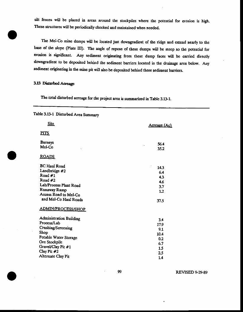
silt fences wiil be Placed in areas around the stockpiles where the potential for erosion is high.These structures will be periodically checked and maintained when needed.
The Mel-Co mins dumps will be located just downgradient of the ridge and cxtend nearly to thebase of the slope (Plate ltr;. The a"gle of repose of these durnps will be steep so the potential forerosion i5 signifigant. Any s,E.limsat originating from these dump faces will be carried directlydowngradient to be deposited behind the sediment barriers located in the drainage area below. Anysediment origbating in the rni"e pit will also be deposited behind thcse sediment barriers.
3.1!l DisturbedAcreagc
The total disturbed acreage for the project area is summarized in Table 3.ui-1.
Table 3.1i1-1 Disturbed Ar:s3 gumrnary
S!!e.
EITS
BarneysMel-Co
ROADS
BC Haul RoadLandbridge #2Road #1Road #2Iab/Process Plant RoadRunawayRampAccess Road to Mel-C-oand Mel-Co Haul Roads
ADMINIPROCESS/SHOP
{rlmining{ion BuildirgProcess/LabCrushing/SoeeningShopPotable Water StorageOre StockpileGraveVClay Pit #1ClayPit #2Alternate ClayPit
Acreaee (Ac)
375
56.435.2
1436.4434.63.71.2
3.417.99.1
10.40.26.t15251.4
99 REVISED 9-29-89
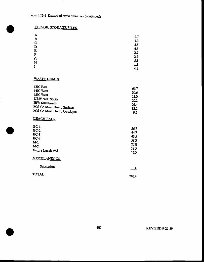
Table 3.L11 Disturbed .fusx grrm,nary (continued)
TOPSOILSTORAGE PILES
WASTE DUMPS
6300 East6400 West6500 WestUBW 6600 SouthIBW 6400 SouthMel-Co Mine Dr"'tp SurfaceMel-Co Mine Dump Outslopes
LEACH PADS
BC-1BC-2BC-3BC-4M-1M-2Future Leach pad
MISCEI.ANEOUS
Substation
TOTAL
2.71.05543z72.755154.1
6.730.611.0m226.433292
fi.74.7435583n.8185165
ABcDEFGHI
.4
7L0.4
100 REVISED 9-29-89
THIS PAGE INTENTIONALLY LEFT BI.A}TIC
PAGES lOl.lAND 101.2 HAVE BEEN ELIMINATED.
101 REVISED 9-n-89
4O IMPACTASSESSMENT
The predicted impacts of the Barnep Canyon Projoct ou the environment are eirmmarizcd below.
4I Surfref,rahr
Barneys Geak vrhich florm from Baraep Caayon is intermittcat * ie hcadwaters and percnnial
ot'€r a mile reach adjacent to the south side of the Barneys Canyon open pit and mine dgmp. The
location of Barneys Creek is shoc/tr in Ptate I. It is anticipated that the project will hara no
impact on Baraeys Creek" Other naturat drainages in the arca contain intermittent streams. The
rnining operations will intemrpt sermal of the intermittent drainages in the area The major
wi[ be located at the mine waste drrmps whic,h will fill areas cfiere natural drainages
currcutly cxisr Additioaal project facilities influenciag surface water runoff from the site include
haul roads, oper pit$ the cnrsher sitg and the leach facilities.
The opcrational runofr control plan has been designed so that the site will have zero discharge
during storm events with a l$'year, 2#hour recurreac€ interval. Hencc, ns impact to offsite
surface water is anticipatcd"
Despite the modifications that the project will make to the locat cpheneral ard intsrgittent
drainage pattern, these modifications will have no effect on existing non wildlife water use. The
creation of impoundments on the site nay harrc a beneficial afrect on wildlife and liwstock that will
use the area following recramation by providing seasouar water supplies.
Lgz
42 CroundWarcr
The Barncp Canlon rnining projcct is anticipatcd to haw os i'npact on grormdsratcr quality
bccausc all lcach solutions will be coataincd on sitc in tincd nufacc impoundmcnts or within thc
liacd heap lcach pads.
ltc groundwatcr quastity Eay bc altcred by dcwatering of tbs Barucp Caayon pit during rnining
opcratious Bccauc of the ptanned dcpth of thc Baracys caryoa pit, -i',i'g bclow thc water tablc
is e'ryccred to occ[r. To coatrol watcr in thc pig dewatcring will be rcquircd usi,'g dccp
pcnetration production *dls placcd arouod thc circumfcrcacc of thc pir Ttis puurpiag will rcnorr
watcr Aom thc bcdrock aquifcr creating a oone of dcprcssion bclow thc pit arca 1tis couc of
dcprcssiou is aot anticipatcd to influence ncarby watcr urc\ giwu thc long distaacc and thc low
permeability of the aquifer. All intcrccptcd pit watcr will be utitizcd as neccssary for dust control
on thc roadg ald for proccss rnrkggp watcr. Watcr dghts wiu bc 6lcd with thc Division of Water
Rights for the rolumc of water to be ucd duri4g opcratioos. It is aot anticipatcd rhal inflsw ts
the pit wi[ yield more watcr than s3s bc uscd dudng opcratious, howcver, if this tatcs place,
cxccss water will bc dischargcd into one or Eors ucarby drainagps whcrc &c watcr qrill i'npound
bchitld thc railroad impouadacats on thc castcru cdgc of the property. No dischargc into the tirre
strc^aE channel of Barncp Gcck will take place. thc water will infiltratc into the groqnd bchind
the gradc. No discharge pcrnit wiu be accdcd bccause rhic q6tsl will not lcaw tbc propcrty.
The Mcl'Co Mine Pit and adjaccnt waste dump will also f,gys Erinimal impacts on the
groundwater. Darncs and Moore (1988) determind based upon piezomcters conpleted in cxploration
dri[ holes' that tbe approxinatc clcration of the watcr table bcueath Mel-C.o to bc 6800 feet
(AI\'rsL)' c\rrent miac plo'q rcflect the maxinum possible pit dcpth and indicate that the clcvatioa
of thc pit bonom will aot exoccd a dcpth of 6900 fcct. Thercfore, no impact upon grouldwatcr
1(B REVISED 7.2G88
quantity or qrtaliSy from the Mel-Co pit is anticipatcd.
43 SoilRcsourccs
Opcrational and post-opcrational nmoE control plans prcrrcut the crosion of in-place and
stoc&Pilcd topsoils. Duc to stccp slopcs and relatcd workcr safcty requircncats, vzrianccs for
topsoil salvaging aad rcplacencat arc bcing songhq as disossed in Sccion 6.0. With tbc cxocption
of arcas proposcd for narianccg topsoil wi[ bc sahagcd from all other disturbcd arcas. Su6cisnt
topsoil will bc salragcd to insrue that all nrfaccs rcccivirg topsoil dudng rcclanation wiu bc
covcrcd by at lcast onc foot of topsoil Reptaced topsoil wi[ bc rcrrgetated with an appropriate
sced mix both for the purpose of erosion prcrcation and for wildlife and cattle forage. Soil
stockpilcs wiU bc protcctcd &om crosion with an intcrim corcr of grass. Soil resoruces witl,
thcrcforg bc protectcd to tbe maximum cscnt that prudcnt and safc rnining praaiccs allow.
4.4 Gitical Wildlifc llabitats
The open pits will be thc onty parts of the disturbcd areas that will not be rcclaimcd and,
thcrcforc, will not bc arailablc as highquality wildlifc habitat as thcy arc now. The project arca is
importaat habitat to both decr and ct\ howcrcr, &c toss of forage and covcr will be rninimal in thc
oontcs of tbe proicct as a wholc. Possiblc changcs in rigratioa routcs will only be temporary
gircn thc short lifc of the rninc. tf,is ninimal impact to tbc wildlifc habitat will bc mitigatcd
somewhat by thc crcation of wildlife watering sites in impoundmeuts in the Barneys Canyon pit and
behind mine dumps. In addition, Kcnaecott's practice of allowiog ao hunti'g on its property will
climinatc the impacts of combined [nnting prcssure and babitat loss on the herds.
thc Division of Wildlife Rcsources (D\lR) has becn informed of the Barucp C-anyon project
REVISED 7-2A-8
rclcing for tbcir reconncDdations oolcaraing clk catving habitat and c& and dccr winter mnge.
Kcanccott and the Division of OiL Gas and lfining harc bccu informcd by thc DWR that the projcct
opcrations will not adrrcrscly affcct clt calving hsbitat and rhat thc only r,,irigqtio lcccssary will
bc to rcducc travel in thc main brarch of Dry Fork and that portion of Baracp Canlou above thc
ffi foot clcratioa as much as possiblc dndDg calving 6casoD. Ncithcr thc Mcl€o or Barucys
Caapn opcrations will rcquire aoccss to thcsc areas. Kcnnccott crnnot of coursc rcsaia acccss to
priratc landowncrs or lcasc holdcn rvho uay rcquirc a@css to propcrties il thcsc cantoss or to its
o*a pcrsoaacl nrho any harrs to entcr tbc nqin fuassfi of Dry ForL for thc purposcs of property
amintcnancc or water monitoriag.
45 AirQoality
4i1 smiscioss rculting from thc rnining opcrations wi[ bs ftrgtirc dust and dicscl cmissions. A
aumber of point Eolltcc air cmission Bourccs will occur within thc proccss plaat area Thc principal
point eourcc cnissions will bc dust from thc cnrshing aad scrccning opcrations Dstailcd air
earissioas calcolations arc incorporated in tGonccotfs T.Ioticc of Istcnt to Commcace lvfining aad
Gold Proccssing opcratioaq Barnep Canyon Projccq Salt Late County, Utall Subnincd to Utah
Burcau of Air Oualiy (AONOD.
Ifuunccott's cnission control plals for thc projcct will incorporatq as Utah Burcau of Air
aua[ty rcgulations rcquirc bcst arailable control tcc.hnolog for supprcssion of cmissious. Thc
controllcd cEissioas calculations in the above.rcfcrcnccd AQNOI indicate that thc Baruep Canyon
projcct will not bc a -ajor cmission souroe undcr Fcdcral Prcrcutiou of Significant Dsterioration
(PSD) rcgulations. Thercforc it is concluded that &c project will not causc a significant
dctcrioration of air qudity in thc area.
105 REVTSED 7-20-88
46 hblic l{calrh a"dsaf*y
.[ll rrrining and proccss opcr,ations will bc opcratcd iD firll aocordance with safcty rcgutations
administcrcd by thc Fcdcral Minc Safcty and Hcatth drftninirtration (MSILd). The ocaryational safcty
rnd hcalth Program will aot only protcct worlccr safcty and hcatt\ but also tbat of mcobcrs of the
gcncral public tbat will visit tbc propcrty. Maintcnancc of a safc on-sitc work cnvironmcnt and
adhcrcne to tbc air cnission control progran will iuure that no harnful airborne particulatc or
elcnical cmissions will lcaw thcpropcrty.
IGnaccotf by virtuc of ie cacDsive land ouruenhip in the area, coatrols all acccss to the
propcrty. Hcnce, an cffcctive safcty buffcr zonc is adjaccat to the projca sitc. In additiou to
otrcrall controlled acccss aad the site safcty prqgam, other specific safcty Bsasurcs wiu be takcn to
firthcr insruc public safcty. Ttesc mcasurcs will iacludc loc&cd gatcs at all acccss poina ufrcn
opcrations arc dormant, fcnccs around all proccss arcaE and scclrity grurds to controt public acccss
at all timcs dndng the tifc of the project Warning cignc ajd safcty bcrns wiU bc installcd
adjacent to pit highwa[s following complction of nining Es part of rcclamation In additioq all
Proccss facilitics wiu bc rsdaimcd aftcr any qanide-bcaring or othcr toxic-materials-bearing wastes
are ueutralizcd or safclyrcnovcd from thc proparty.
105.1 REVISED 7-20.,88
5J RECXAMAIIONPI.AI{
5J Pd-niningLandUsc
The post-mining land use for the rcslaimsd rnins dunps and leach pads will be for wildlifc
habitat and livestock g;azing. The post-rnining land use for the open pits wi[ be ss.timeaf control.
The pits will contain sediment eroded from the open pit walls. The Barncys Canyon pit wiu serve a
secondary purpose ofproviding a souroe ofwater for wildlife.
52 Demolitim andDispcal
521 FaciliticsRclnoval
AII non-earthen facilities will either be transported from the site for rse elsewherg salvaged, or
demolished if necessary. Any paved surfaces will be removed and handled as demolition debris as
described below. The various facirities will be removed or disposed as follows:
will be salvaged s1 6encported from the site for use
elsewhere;
buildines win be salraged or demolished and removed from the site, untess they are required for
o11"1 nsp-hining use.
oowerlines and substations will be removed and salvaged upon completion of the operations,
unless they are preserved for a continued non-mining usei
fuel and explosives storaee facilities will be salvaged or transported off-site for disposal; and
fences will be removed and salvaged or jn,,ked following completion of reclamation.
Necessary security meastues will be maintained until satisfactory reclamation has been achieved.
106 REVTSED 9-29-89
522 DcmolitionDebris Dlpcal
Demolition debris that cannot be salvaged will be deposited in a permitted solid waste lan.rfin.
523 llazardous Substanccs
As the data presented above in Section 3.11 demonstrate, it is not anticipated that materials left
on site following reclamation will be hazard6us. As discussed below, each heap leach installation
will be rinsed and have its cyanide neutralized prior to regrading and reclo-ation. Mine dumps will
not be toxic. Any other process waste materials that accumulate on site, either in containers or
impoundments will be disposed of propcrly, taking into account potential hazardous characteristics.
53 Rcgrading and hoess Facilities Ctosnre
Proposed procedures fel rnins dump and process facilities regrading and/or closure are presented
below.
53.1 OpenPits
Open pits will not be used as sites of rnine dumps and" therefore, will not be backfilled. The
pits will serve as catchment basins and prevent release of sediment eroded from the pit walls. The
pits will not be revegetated or topsoiled. Pit stopes will reach 47 degrees and, therefore, slightly
exceed thc Division's maximum slope requirement of 45 degrees. Variances to acco'n,,,odate plans for
the final condition of the open pits are requested in Section 6.0. Safety berms or fences will be
installed along the margins of all pit highwals.
r07 REVTSED 9-29-89
532 lvfineWasteDunps
Waste dump outslopes will be developed during mining at a slope of approxim ately 37 degrees.
All Barneys Canyon pit mi"e dumps wiil be regraded to a slope of 2h:lv (22 degrees). The regraded
bench outslopes will be terraced for the purpose of runoff and erosion control. Teraces will be
approximately 10 feet in width and will be constructed at vertical intervals of 100 feet. The
regraded Barnep Canyon dumps will be covered with approximately one foot of topsoil and
revegetated accordi'g to the revegetation plan presentcd in Section 5J througb 5.g.
The configurations of the Mel-Co rnine dumps have been revised as a result of the decision to
increase the size of the Mel-Co open pit. The outslopes of the small dumps or fills above tbe 7200
drrrnp will be regraded to a slope of 2h:1v (Zl degrees). The outslopes of the Zl00 and ?200 dumps
will not be regraded because doings so would result in additional disturbance of the watershed
includi"g adjacent hillsidss' and the ephemeral channel in the canyon below the dumps. Sufhcient
topsoil to cover the regraded slopes of the upper Mel-Co dumps and all dump surfaces will be
borrowed and stockpiled from the Mel-Co site.
533 Hcap I-each Pads and Sohrtion ponds
When a leach pad is completed" it will be rinsed to remove the cyanide solutions, draine4 and
left for recla-ation at the close of all operations. The neutratization criteria will be determined by
the Water Pollution Control Committee or the Bureau of Water pollution Control (Bwpc) at the time
of decommissisning. fr" oeut tlioution criteria will ensure that no degradation of the surface or
groundwater quatity or beneficial uses thereof takes place following regarling and revegetation of
the heaps.
108 REVISED 9-29-89
The closure Process *iU bcg" by terminating thc addition of NaOH and NaCN to the barren
pond water and allowing the pH of the circulating leach solutions to gradually adjrst to a natural
pH of about 7. The neutral solution pH wiU cause the CN in the wet ore to gradually be converted
to volatile HCN which will be liberated to the air-filled voids within the heap. This HCN will
gradually and harmlessly diffirse to the surface of the heap where it will be released into the
atmosphere. The final neg6nlizali6n procedures will be described in a closure plaa to be reviewed
and approved by BWPC six montbs prior to beginning neutralization of any pad.
When the heap har lssn asutratize{ ifus maksup water flow to the barren pond will be turned
off and the water in the pregnant and barren ponds will either be pumped to another active leach
pad or evaporated. The ponds will then be allowed to dry ssd lgneining sludges will be sampled for
EP toxicity characteristics. All solid wastes will be properly disposed of taking into account their
chemical characteristics. The poud liners will then be removed from the anchor trenches and folded
into the ponds. The pond areas will then be backfilled with earth, and topsoil from nearby
stockpiles will be spread evenly over the regraded surface.
The leach heaps will be re-contoured to gradually rounded slopes of 2h:1v or less. The re-
contouring process will include pushing neutralized heap material over the pad narginal dikes to
cover ttre cxposed liner. Topsoil from the stockpiles will then be spread evenly over the re-
contoured surface and the specified vegetation mixfue will be established.
The rinsed leach solution pipelines will be taken up and removed from the site. The liners in
the pipeline trenches outside of the leach pads will be removed from the trenches, rolled up, and
disposed in the solution pond excavations prior to their being backfilled. The trenches will then be
regraded, topsoiled" and revegetated.
109 REVISED 9-29-89
5.4 SoilMatcrials
5.41 TopsoilApdicatim
During reclamation" all disturbed areas, with the exceptions of the open pits, the clay borrow
pits, and the Mel-Co 2100 and 72gg drrmps, will be covercd with topsoil having s sqminal thickness
of 12 inches; areas to receive topsoil are described in section 5.4.3.
Kennecott commits to placement of one foot of topsoil on all distrubed slopes having an
outslope of 2hl1v or less. A revegetation test plot progrem, designed to determine if the Met-Co
drrmp material can be ditectly revegetated will be developed; however the design sf this progran will
not be included ii 1f,s rnining and reclamation plan at rhis time.
5.42 TopsoilHandlhg
The topsoil redistribution will be carried out during the su--er in anticipation of fall seedi,g.
Thus the soil will be relatively dry and compaction minirnized. Minimidng topsoil compaction is very
important considering the clays and clay teams presosl is many of the soil tlpes, especialty the
Harker and Dry Creek soils. Topsoil materials will be noved with a scraper or loader-d'rnp truck
operation and will require some sprearling with a blade. The contractor will be cautioned to keep
tbe soil suface rough and to avoid blading to obtain a smooth surface. Evenness of depth will be
sacrificed fq1 lenghnsss of surface.
To relieve compaction all topsoiled areas will be ripped to a depth of 12" with the rippers set at
12n spaci"g.
110 REVISED 9-29-89
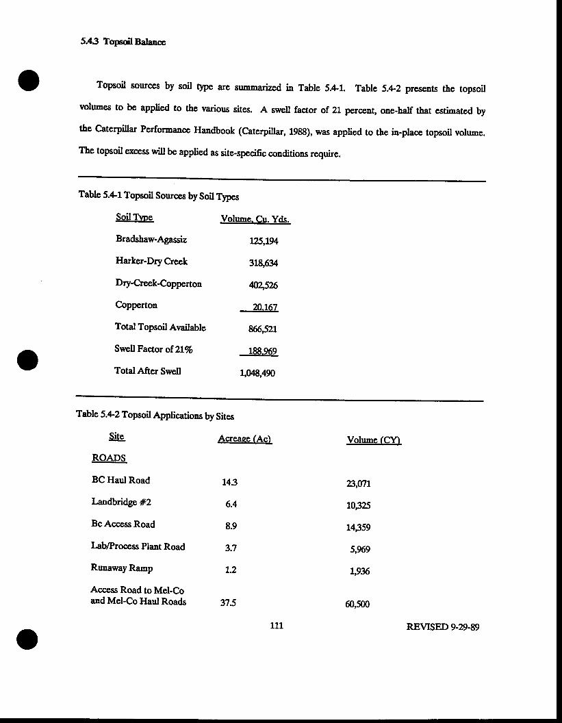
5.43 TopsoilBalancc
Topsoil sour@s by soil tlpe are sn,nmarized in Table 5.4-1. Table 5.42 presents the topsoil
rolumes to be applied to the rarious sites. A swell factor of 21 perceng one-half tbat estimated by
the Caterpillar Performance Handbook (Caterpillar, 1988), was applied to the in-place topsoil vol,,-e.
The topsoil excess will be applied as site-specific conditions require.
Table 5.4-1 Topsoil Sources by Soil T!'pes
SoilTbe
Bradshaw-Ag;assiz
Harker-Dry Creck
Dry-Creek-Copperton
Copperton
Total Topsoil Available
Swell Factor of.ZL%
TotalAfter Swell
Volume. Cu. Yds.
l?l'Lg4
319,63
q2,5%
nJ67
ffi,521
188.969
1,049,490
Table 5.4-2 Topsoil Applications by Sites
&.ROADS
BC Haul Road
Landbridge #2
BcAccess Road
LablProcess Plant Road
RunawayRamp
Access Road to Mel-Coand Mel-Co Haul Roads
Acreaee (Ac)
143
6.4
8.9
3.7
t2
n5
Volume (CY-)
23,07L
10,325
r4359
5,969
1,936
60,500
111 REVISED 9-D.89
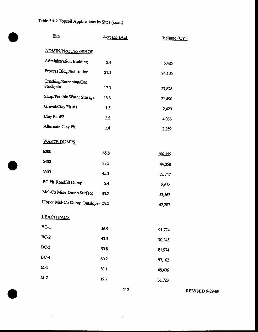
Table 5.*2 Topsoil Applications by Sites (cont.)
S!!e.
ADMIN/PROCESS/SHOP
{drninistl{ion Building
Process Bldg"/Substation
Crushing/S oeening/OreStockpile
ShoplPotable Water Storage
GraveVClay Pir #1
ClayPit #2
Alternate Clay pit
WASTE DUMPS
6300
ffi
6500
BC pit Roadfill D,rmp
LEACH PADS
BC-1
BC-2
BC-3
BC-4
M-1
M-2
Mel-Co Mine Dump Surface 33.2
Upper Mel-C.o prrmp Outslopes 262
Acreaee (Ac)
3.4
2L.l
173
l:}.3
15
25
t.4
65.8
273
45.1
5.4
Volune (C\t)
5,485
34,105
n,876
21,490
44n
4033
2,89
56.9
43.5
50.8
ffi2
30.1
19.7
106,159
44,059
72,747
&658
53,563
44247
e\n4
70,v+5
81,974
n,L62
4,496
31"tls
L12 REVTSED 9-29-89
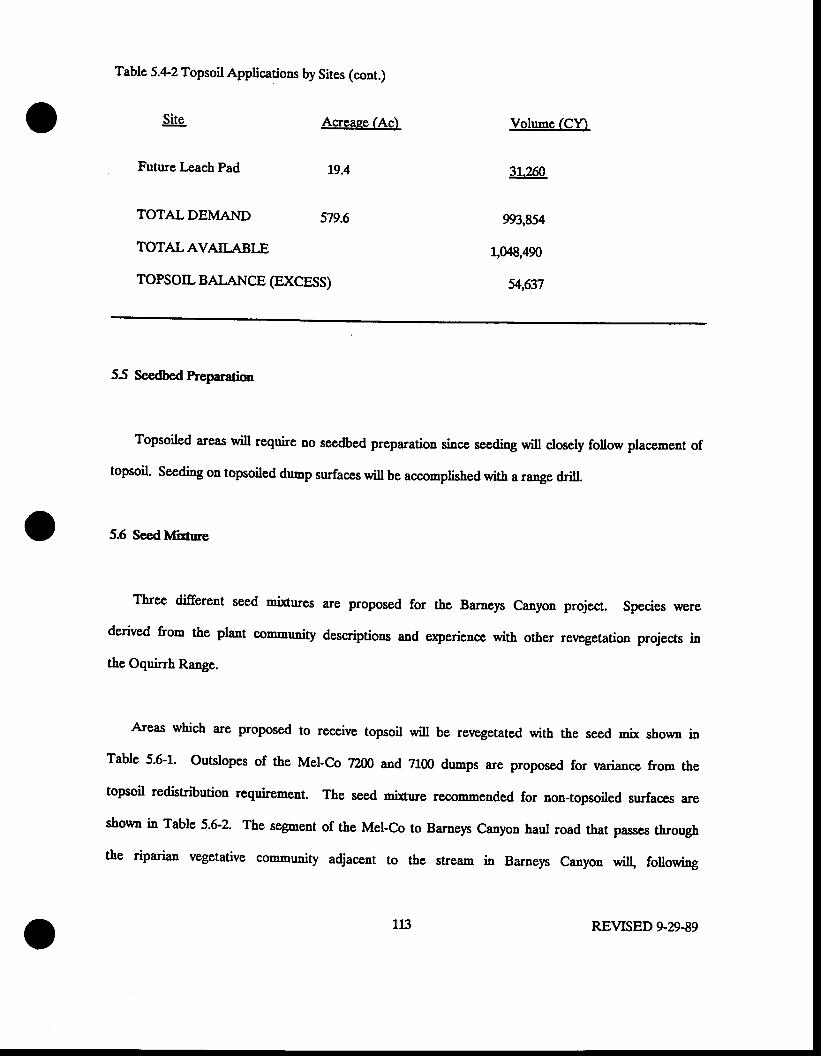
Table 5.4-2 Topsoil Applicarions by Sites (cont.)
S!!s.
Futue l-each Pad
TOTAL DEMAND
TOTALAVAII.ABLE
TOPSOI BAT.ANCE (EXCESS)
Acreaee (Ac)
19.4
579.6
Volume (CY)
3L.zffi
993,954
1,048,490
y,637
55 SeedbedPreparation
Topsoiled areas will require no seedbed preparation since seedi.g will closely follow placement of
topsoil. seedi'g on topsoiled dr"np surfaces will be 6scomprishgd with 6 yarrge drill.
5.6 S€edleure
Three different seed mixtures are proposed for the Barneys Canyon projecl Species were
derived from the plant cs-"'unity descriptions and experience with other revegetation projects in
the Oquirrh ftange.
Areas which are proposed to receive topsoil will be revegetated with the seed mix shown in
Table 5'6-1' Outslopes of the Mel-Co 7200 and 71gg drrmps are proposed for variance from the
topsoil redistribution requirement. The seed mirure recornmended for non-topsoiled surfaces are
shown in Table 5.62. The segment of the Mel-Co to Barnep Canyon haul road that passes througb
tbe riparian vegetative community a-djacent to the streem in Barneys Canyon wi[ following
lUi REVISED 9-29-89
aPplication of topsoit be revegetated using the proposed riparian seed mixture which is presented in
Table 5.63.
An even mirrue of Gambel oalg rabbitbnrsh and snowberry tube stock planted in clumps of 3 to
5 each will be planted at a rate of ti5 plants per acre, three times tle application rate proposed
for the topsoiled surfaces. The planting procedure for each clu-p will begin with excavation of an
over-sized hole which will be lined with mulch. A slow-release fertilizer pellet will be placed at the
bottom of each hole. The tube stock will be then planted and the hole filled sad larnped. A
mircure of legume seed will be hand-applied to the surface of each planring site for enhancement of
nitrogen development in the planting nefirrm. The Division will establish a survival rate, as a
percentage of total seedlings planted for the un-topsoiled drrmpS surface. This suwival rate is
currently ssririlatsd to be 30 perceat. ltis survival rate will be achieved at the end of the three
year period following completion of reclamation.
As a result of discussions with DwR personne! it has been agreed that additional legumes and
forbs will be added to the revegetation seed mix to improve the spring forage for deer and elk in
the reclained areas of the Project. DWR personnel feel that the addition of these species ts this
large reclaimed area wi[ significantly improve the early spring forage above what is currently
present' This improved forage over this large reclaimed area will provide enhanced habitat to both
deer and elk' Therefore, the current reclamation plan with the modified seed mix is, according to
DwR, the best means of enhancing the post-rnining use of the reclaimed area.
Kennecott understands that the need for topsoil on the tops of benches cut into Mel-Co mine
dunp outslopes will be based upon the suc@ss of revegetation test plot work on tle dumps to be
conducted during operations. Kennecott will stockpile sufEcient additional topsoil to handle this
possible need. The benches will be topsoiled only if the revegetation test plot program indicates
REVISED 9-29-89

that direct revegetation of the d'mp materials will not be successful. To the ercent possible, the
dump outslope size will be minirnizcd by co,,fir,i'g waste as close as possible to the Mel-Co pit in
the drainage occupied by the ?100 dump and by mini'niing to the e*ent possible, the amount of
waste rock placed on the 7200 dump. It is not possible to reduce the size of the Mel-Co dump.
115 REVISED 9-29-89
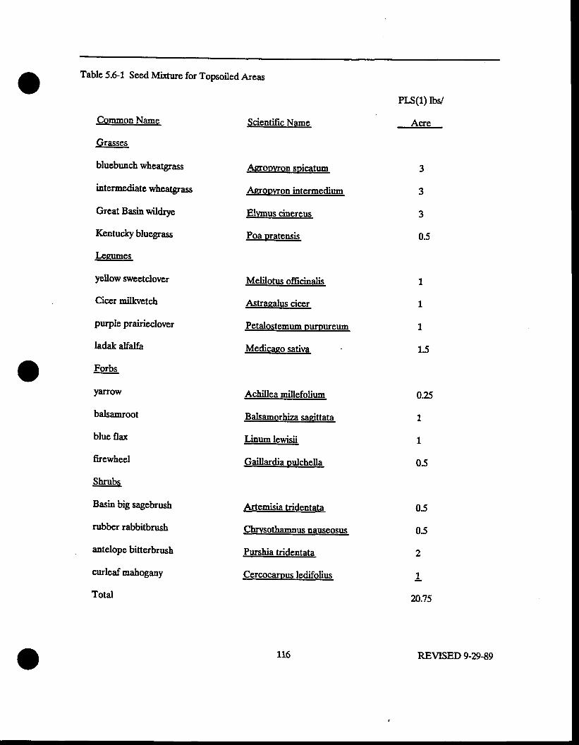
Table 5.6-1 Seed Mi*ure for Topsoiled Areas
Common Name
Grasses
bluebunch wheatgrass
intermediate wheatgrass
Great Basin wildrye
Kentuclry bluegrass
Legumes
yellow sq'eetclover
Cicer milkvetch
purple prairieclover
ladak alfalfa
Forbs
yarrow
balsamroot
blue fla:r
firewheel
Shrubs
Basin big s4gebrush
rubber rabbitbrush
antelope bitterbrush
curleaf mahogany
Totd
Scientific Name
Asroowon soicatum
Asoowon intermedium
Elvmus cinereus
Poa pratensis
Melilotus officinalis
Astrasalus ciccr
Petalostemum oumureum
Medicaeo sativa
Achillea millefolium
Balsamorhiza sasittata
Linum lewisii
Gaillardia oulchella
Artemisia tridentata
Chrrnothannus nauseosus
Purshia tridentata
Cercocamus ledifolius
Prs(l) rbv
Acre
I
1
1
1.5
0.25
1
1
0.5
05
05
2
1
20.75
3
3
3
0.5
116 REVISED 9-29-89
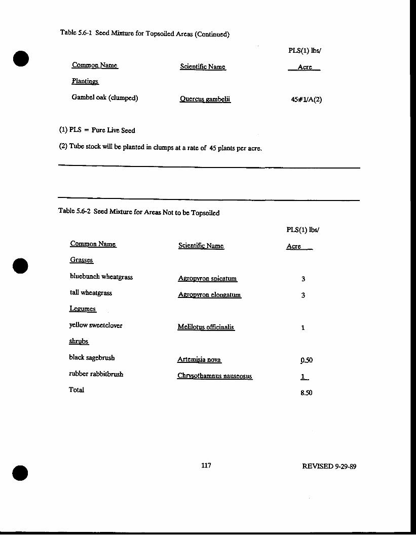
Table 5.61 Seed Mirure for Topsoiled Areas (Continued)
Common Name
Plantinss
Gambel oak (clumped)
(1) PIS = Pure Live Seed
Scientific Name
Ouercus sambelii
(2) Tube stock will be planted in clumps at a rate of 45 plans per acre.
PIs(l) rbv
Acre
4s#uA(2)
Table 5.62 Seed Mi:Crue for Areas Not to be Topsoiled
CommonNane
Grasses
bluebunch wheatgrass
tall wheatgrass
Legumes
yellow sweetclover
shrubs
black sagebrush
rubber rabbitbrush
Total
Scientifrc Name
Agoowon spicatum
Agroowon eloneatum
Melilotus officinalis
Artemisia nova
Chnaothamnus nauseosus
PH(l) rbv
Acre
-050
I
8.50
tn REVTSED 9-29-89
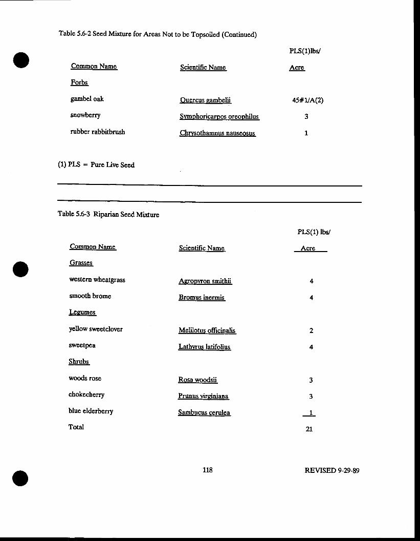
Table 5.6-2 Seed Mixnre for Areas Not to be Topsoiled (Continued)
Common Name
Forbs
gambel oak
snowberry
rubber rabbitbrush
(1) PIS = Pure Uve Seed
Scientific Name
Ouercus sambelii
Srmaohoricamos oreophilus
Chrvsothamnus nauseosus
PIs(l)lbv
Acre
4s#u^Q)
3
1
Table 5.6-3 Riparian Seed Mixrure
Common Name
Grasses
western wheatgrass
smooth brome
Lezumes
yellow sweetclover
sweetpea
Shrubs
woods rose
chokecherry
blue elderberry
Totd
Scientific Name
Aeroo\Ton smithii
Bromus inermis
Melilotus offrcinalis
Lathwus latifolius
Rosa woodsii
Prunus viroiniasa
Sambucus cerulea
P$(1) lbv
Acre
3
3
1
2l
2
4
118 REVISED 9-29-89
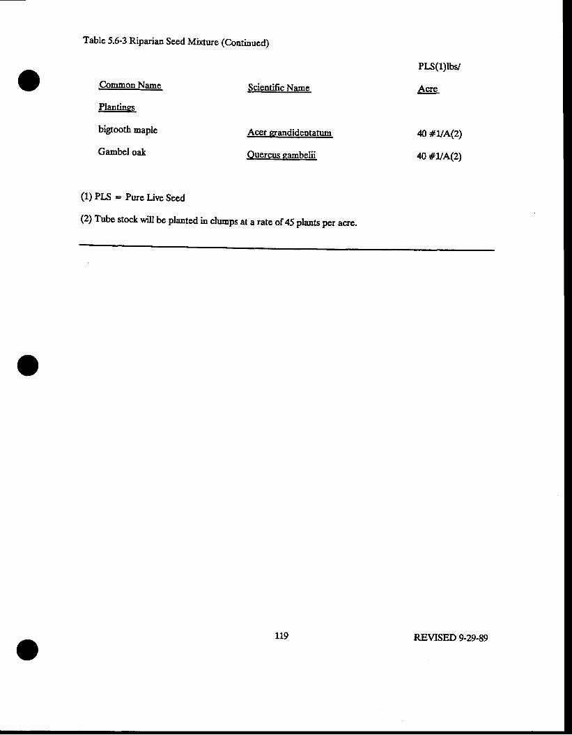
Table 5.6-3 Riparian Seed Mlcure (Continued)
Common Nane
Plantines
bigtooth maple
Gambel oak
Scientific Name
Acer prandidentatum
Ouercus sambelii
PIs(l)lby
Acre
n #uA(z)
q #uA(z\
(1) PLS = Pure Live Seed
(2) Tube stock will be planted in clumps at a rato of 45 plants per acre.
119 REVISED 9-29-89
5.7 ScedingMethods
Topsoiled dump top surfaces will be seeded with a range drill and topsoiled dumps slopes will be
seeded with a hydroseeder. $ss.ling will take placc in the fall prior to snowfall The seeding depth
for drill-placed seed will be 054.75" at the rate of application specified in the seed mirures
presented in Section 5.6. Since the seed drilling will be the last step in revegetation, the fertilizer
and mulch will be turned into the soil by ths .tisks on the drill
Variances from the requirements for both vegetative diversity and percent vcgetative cover for
the outslopes of the Mel'Co ?100 and 7200 dunp sites harre been requested and are discussed in
Section 6.0.
Keunecott will use the Division's recommended methodologt for hydroseerting the steep, non-
topsoiled slopes of the Mel-Co ?100 and 7200 slopes. These slopes wi[ bs hydroseeded in two steps.
The seed nix will be applied first; then, in the second application, the fertilizer and hydromulch wiu
be applied. A tackifier, included in the second application will be used to hold the seed and mulch
in place after drying. Kennecoft prefers to retain the existi'g proposed sse.ting method for the
regraded, topsoiled 2.h/1v slopes.
The planting stock will be tube stock and wiu be hand planted in early spnng at snowmelt.
Planting will be in clumps of three in sites with aspect and slope to maxinize moisturc enrrapnent.
The three plants will be located in the ccnter of a small basin
r20 REVISED 9-29-89
5a Ferdizatim and Mulcting
54.1 Fcrtilizatim ofTopsdcdAr€as
The goal 6f fsltilization is to raise the available phosphorus and nitrogen concentrations to 25
ppq and 0.@ respectively and to maintain the organic Eatter at 15 pcrcent. This will be
accomplished by utilizing green alfalfa hay io combination yigfu rtiamnonium-phosphate fertilizer in
the fall seeding schedule. This fertilizer will provide the nitrogen required for seedling gronth in
the first gfowing EeasoD-
The hay at 4,000 pounds per acre will provide nitrogen, phosphons, and potassium at the rates
of 100 poun& per acre, 20 po'nds per a.'e, and 94 pounds per acre, respectively.
The diammoniun-phosphate fertilizer 18460 at 310 pounds per acre will provide 49 pounds per
acre ofnitrogen and 64 lbs per acre ofp205.
The diarnrnonium-phosphate fertilizcr will be applied in dry-pellet form with a cyclone spreader
uit following disking of topsoil and prior 1e s6e.ling. A spring application of urea will be by dry
pellet either rrsing a helicopter or a cyclone spreader unit.
During the planting of the sbrubs specieq a fertilizer tablet of 2&lG5 will be inserted in the
hole at root deptb and irrigated. These slow release tablets are designed to provide fertilization to
the ssedlings for two years.
127 REVTSED 9-29-89
5a2 Fcrtilization of Nm-Topsoiled Arcas
Fertilization of non-topsoiled areas (Mel-Co 7100 and ?200 dump outslopes) will be identical in
chemical fertilizer tlpe and quantity as described for the topsoiled area, in Section 5.8.1. Fertilizer,
Eulch' and tackifier will be applied in a slurry by hydroseedi"g methods.
5S3Mulching
Green alfalfa hay will be applied to all topsoiled surfaces and dump tops surfaces. As a mulch
it wi[ increase the organic content of the soils, increase the soil moisture holdi.g capacity, and
provide nutrients for microorganie,rn colsnizatisn. The buildup of microorganismc and the resultant
increase in nutrient cycling capability in the soils facilitates plant establishment and growth.
The hay mulch will be applied at the rate of 4,000 lbs/acre following tippi"g and prior to
sssding. The use of a mulcher or mulch chopper to blow in the hay will allow for even distribution
and dismemberment of stems to allow the disks on the seed drill to turn in the hay particles.
On sites where the seed ddll is unable to function and broadcast seediqg is used the hay will
need to be covered with soil by backdragging or raking.
1?2 REVISED 9-29-89
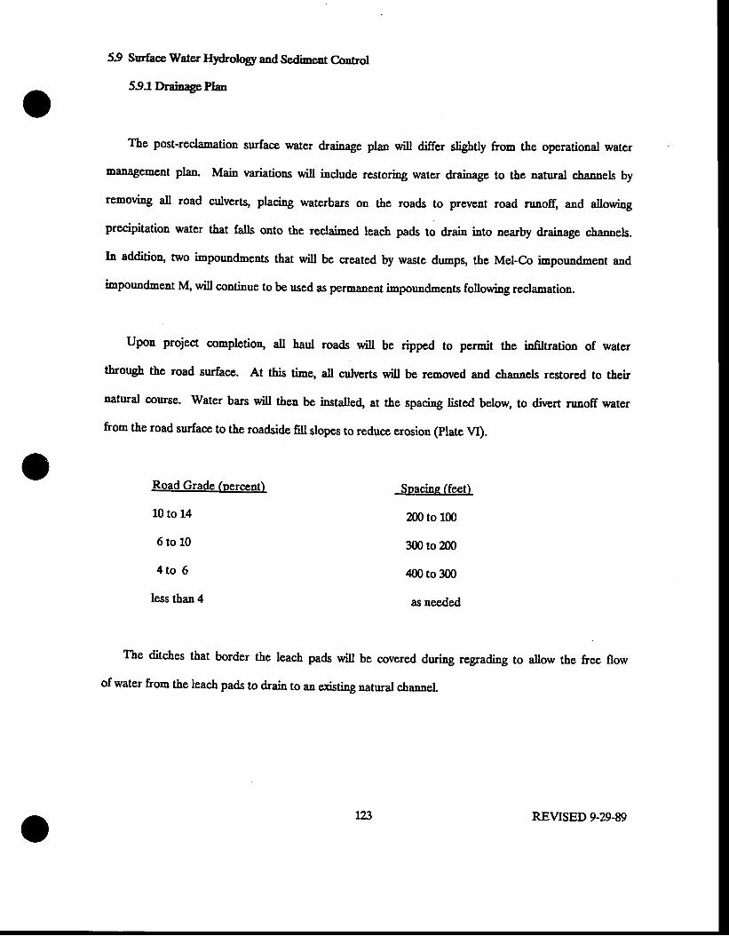
59 Surhce Water Hydrolqg and Sedimcnt Control
59JDrainage Plan
The post-reclanation surface a,31g1 drainage plan will differ slightly from the operational water
rnanagement plan. Main variations will include restoring water drainage to the natural channels by
removing all road culverts, placing waterbars on the roads to prevent road nrnofr, and allowing
precipitation water that falls onto the reclaimed leach pads to drain into nearby drainage sfuanngls.
In addition, two impoundments that will be created by waste dumps, the Mel-Co impoundment and
inpoundment M, will continue to bE used as permanent impounrl-ents following reclamation.
Upon project completion, alt haul roads will be ripped to permit ifug infil6dion of water
through the road surface. At this tims, 4tt culverts will be removed and channels restored to their
natural course. Water bars will then be installe4 at the spacing listed below, to divert runoff water
from the road surface to the roadside fill slopes to rsduce erosion (ptate vI).
Road Grade (percent)
10 to 14
6 t o t 0
4 t o 6
less than 4
Snacine (feet)
200 to 100
300 to Zfi)
zl00 to 300
as needed
The ditches that border the leach pads will be covered during regrading to allow the frce flow
of water from the leach pads to drain to an exisring natural channel.
123 REVISED 9.29-89
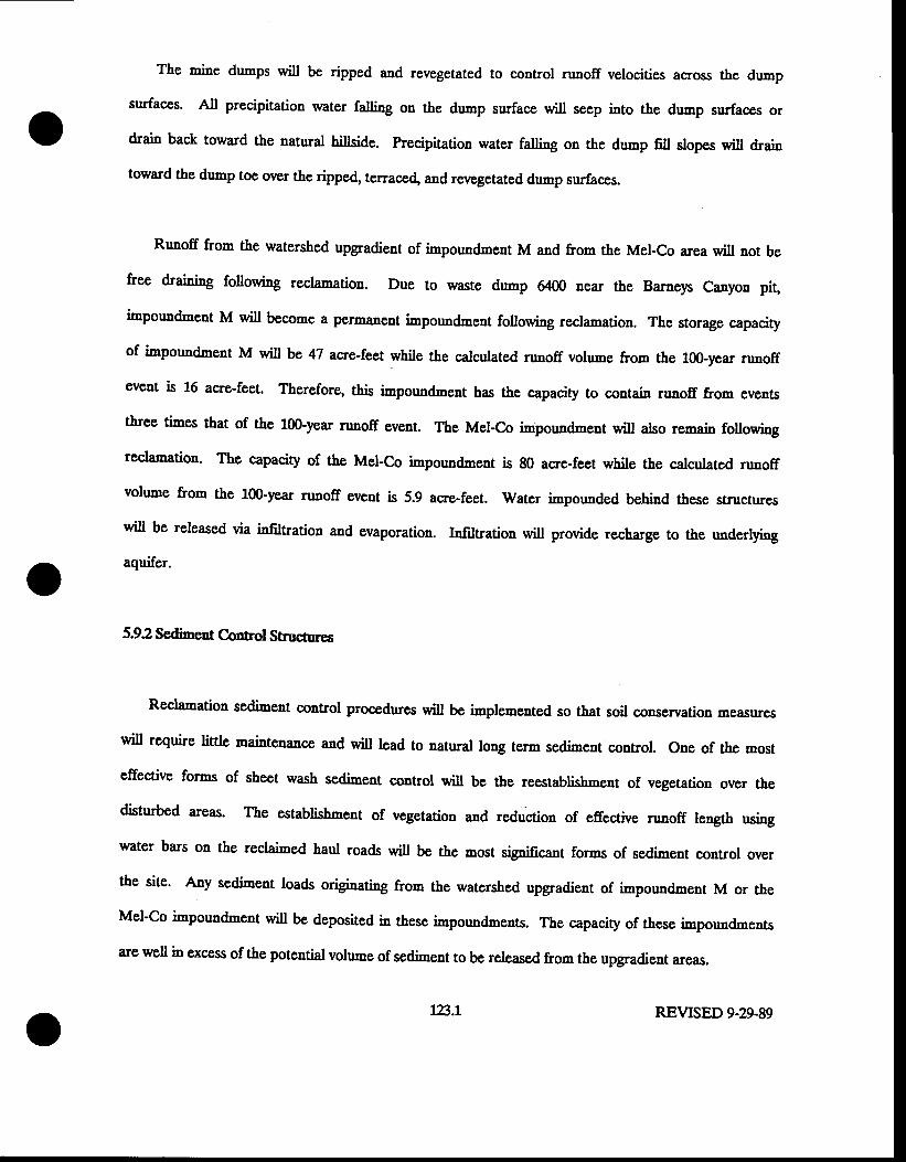
The mine d'mpS will be ripped and revegetated to control runoff velocities across the dump
surfaces. All precipitation water faling on the dunp surface will seep into the drrmp surfaces or
drain back toward the natural hiilcids. precipitation water falling on the d,mp 6ll slopes will drain
toward the dump toe over the ripped terraced and revegetated dump surfaces.
Runoff from the watershed upgradient of impoundment M and from the Mel-Co area will not be
free draining followiag reclamatiou. Due to waste dnnp 6400 near the Barneys Canyon pit,
impoundment M will become a permanent impoundmeut following rcclamation. Thc storage capaciry
of impoundment M will be 47 aqe-teet while the calculated runoff volume from the 100-year runoff
event is 16 acre-feet. Therefore, this impoundment has the capacity to contain runoff from events
tbree times that of the 100-year runoff event. The Mel-Co i,,,pouodment will also remain following
reclamation. The capacity of the Mel-Co impoundment is 80 acre-feet while the calculated runoff
volune from the 100-year runoff event is 5.9 acre-feet. Water impounded behind these structures
will be released via infiltration and evaporation. Infiltration will provide recharge to the underlying
aquifer.
592 Sediment C-onnol Structures
Reclamation ssdirnsnt control procedures will be implemented so that soil conservation measures
will require little maintenance and will lead to natural long term sediment control. one of the most
effective forms of sheet wash sedimest control will be &e reestablishment of vegetation over the
disturbed areas. The establishment of vegetation and reduction of effective runoff length usi,,g
water bars on the reclaimed haul roads will be the most sig,nificanl forms of sediment control over
the site' Any serliment loads originating &om the watershed upgradient of inpoundment M or the
Mel-Co impoundment will be deposited in these impoundments. The capacity of these impounrrments
are well in excess of the potential volume 6f ssdimsnt to be released from the upgradient areas.
13.1 REVTSED 9-29-89
lfts sxisting impoundments crsated by the B&G railroad grade will remain after reclo-ation and
oontinue to fuuction 6s sedimssl control structures.
REVISED 9-29-89
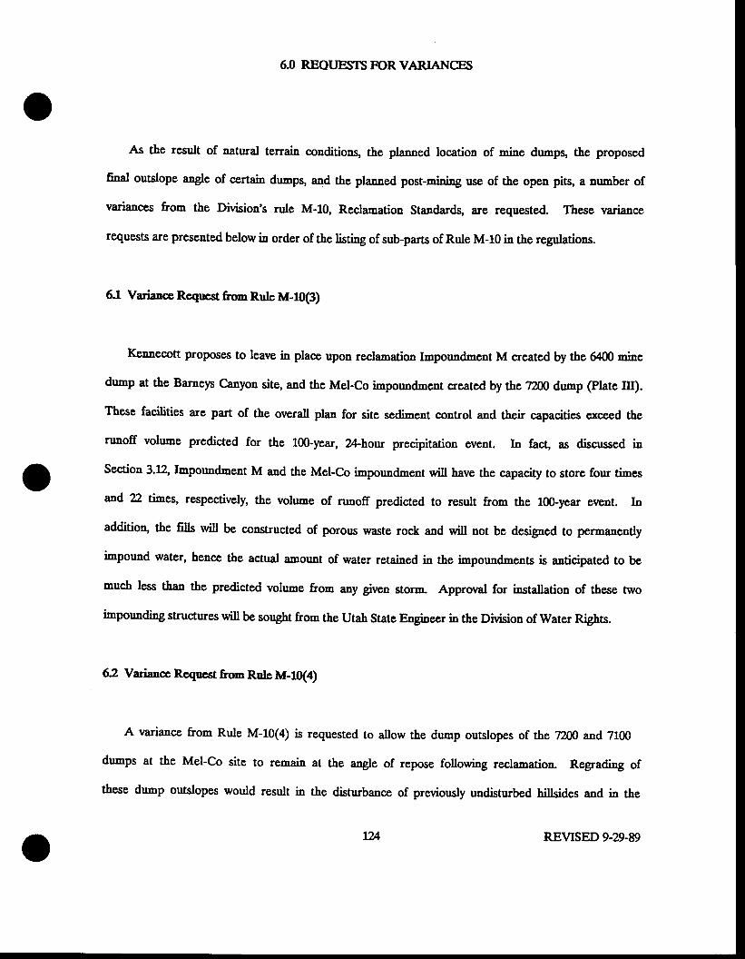
6J REQI.]ESTS F]OR VARIANGS
As the result of natural terrain conditions, the planned location 9f rnins dumps, the proposed
final outslops rngls sf seltain drrmps, and the planned post-mining use of the open pits, a number of
variances from the Division's nrle M-10, Reclamation Standards, are requested. These variance
requests are Presented below in order of the listing of sub-parts of Rule M-10 iD the regulations.
6.1 Variance Request fron Rulc M-10(3)
Kennecott proposes to leave in place upon reclanation Impoundment M created by the f{)0 rnins
dump at the Barneys Canyon site, and the Mel-Co impoundment created by the ?200 dump (Plate III).
These facilities are part of the overall plan for site sediment control and their capacities exceed the
runoff volu"'e predictcd for the lfi)-year, 2Ahour precipitation event. In fac! as discussed in
Section 3.12, Impoundment M and the Mel-Co inpoundment will have the capacity to store four ti-es
and 22 rirnss, lgs,psctively, the volume of runoff predicted to result from the lfi)-year event. In
addition, $s fills will be constructed of porous waste rock and will not be designed to permanently
impound water, hence the actual amount of water retained in the inpoundments is anticipated to be
much less than 1f,s predicted vslrrms from any given storm. Approval for installation of these two
impounding structures will be sought from the Utah State Fngin6er in the Division of Water Rights.
62 Variance Requcst from Rule M-il(a)
A variance from Rule M-10(4) is requested to allow the dump outslopes of the T2D0 and 7L00
dumps at the Mel-Co site to renain at the a"gle of repose following reclamation. Regrading of
these dump outslopes would result i! the disturbance of previously undisturbed hiltsidss and in the
tu REVTSED 9-29-89
disnrrbance of an additional segnent of the ephemeral drainage into which both mine dumps toe out.
Furthermore, these outslopes are situated such that they will not be visible to the general public.
In additioq benches will be constructed every one hundred vertical feet along the dump outslopes to
allow easy access for the hydroseeder and control slope erosion. The dump slopes will be
hy&oseeded to establish minimal vegetative cover. Slope stability analpes presented in Secrion 3.10
demonstrate that the mine dump outslopes are stable.
63 Vadane R€qpcstfrmRule M-10(t
Kennecott does not propose to back-fi!|, rcgradq topsoil or revegetate fts mine open pits.
As discusscd in Secrion 53, Kennecott proposcs to leave highwals in both the Barneys Canyon
and Mel-Co pits which will have an overall slopc angle of 47 degrees; 2 degreas greater than the
mCIdnunr highwa[ angle required by this rule. Stability analyses prepared by lGnnccott and
discnssed in Section 3.7 of this document have demonstrated that the open pit slopes will be stable.
A variance is therefore requestcd. The approrral of the nariance request for pit topsoili'g and
revegetation has been granted in the Division,s May 25letter.
In addition to a varianc€ for slope angtes, Kennecott also requess that rariances for impounding
water ir pits, application of topsoi! and revegetation be granted.
fv[ining operations that consist of nultiple, adjacent, open pits lend themselves to placement of
waste from pits nined late in the life of the operation in pits that were earlier mined 6uL The
Barnep canyon projec! however, does not appear to be such an opcration at this tine. Current
plans call for the Barnep Canyon and Mel-Co pits to be rnined concurrently. Fruthermoys rnins
economics prohibit lsnling of waste from one pit to another. In addition, the geometry of both
REVISED 9-A.89
open pits Prevents $lclcfilling of the pits with rnins qrasfs during fts mining operation. Partial or
complete Sackfilling with waste previously placed in mine dumps is not feasible economically.
As the statements presented above demonstrate, open pit -i"i"g of isolated ore bodies
necessitates tbat this activity Ss n sonsrrmFtive land use. This has been the case historicslly in the
rnining indrstry, and continues to be the case in currently operating and developing rninss itr ths
West today. The lower portions of both pits will be below local grade which will allow them to
serve as sediment retention basins thereby preventing the release of sodiment eroded from the pit
walls.
As has becn previorsly pointed out, the Barnep Canyon nine pit may serve a secondary benefit
to wildlife by providiag a watering site in thtough collection of runoff from the pit walls. Were the
pit to be partiallyback6lle4 this potential source of water would be eliminated.
6.a Variance Rcqrrcst from Rulc M-10(g)
For the reasons discussed above in Section 6.1, Kennecott seeks a variance from this rule to
enable Impoundment M aad the Mel-Co impoundmcnt to remain following reclamation.
65 Variane Rcqucst fronRulo M-10(U)
A variance from parts M-10(12)(a) and M-10(U)@) is requested for the outslopes of the 7200
and 7100 nring dnmps at Mel-Co. The steepness and porous nature of the outslopes and the inability
to topsoil them makes achieving 70 percent of the surface cover found in the adjacent, undisturbed
plant communities ocremely unlikely, especially over a three-year time period.
726 REVISED 9.D-89
6.6 Variance Request from Rulc M-10(B)
For the reasons discussed above in Section 6.1, Kennecott seeks a variance frq6 rhis rule to
enable Tmpounrlrnent M, behind mins dump 6400 and the Mel-Co impound'nent to remain fo[owing
recla-ation.
6.7 Variance Roqpest from Rule M-1O(14)
Kennecott requests a variance from the requirement of re-application of topsoil to the 7200 and
7100 dump outslopes at the Mel-Co site because sprearling topsoil on the 37 degree outslope will
present a safety hazard.
tTl REVISED 9.29-89
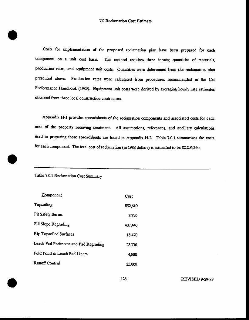
7.0 Reclamation Cost Estimate
Cosg for irnplementation of the proposed reclamation plan have been prepared for each
componeat on a u"it cost basis. This method requires three inputs; qu""tities of materials,
production rates, and equipment rrnit costs. euantities were determined from the reclamation plan
presented above. Production rates were calculated from procedures rscorr,,r,ended in the Cat
Performance Handbook (1989). Equipment unit costs were derived by avereging hourly lsts ssrimxtss
obtained from three local construction contractors.
Appendix H-1 provides spreadshccts of the reclamation components and associated costs for each
area of &e property receiving treatment. All assumptions, references, and ancillary calculations
used in preparing these spreadsheets are found in Appendix H-2. Table 7.0.1 srrmmarizes the costs
for each component. The total cost of reclamation (in 1988 dollars) is ssri'natsd to be $2,206,30.
Table 7.0.1 Reclamation Cost Sumnrary
Comoonent
ToPsoili"g
Pit Safety Berms
Fill Slope Regrading
Rip Topsoiled Surfaces
Leach Pad Perimeter and Pad Regrarting
Fold Pond & Lcach pad r.inEls
RunoffControl
Cost
852,610
3,370
4o7,m
18,470
23,T10
4,990
25,000
128 REVISED 9-29-89
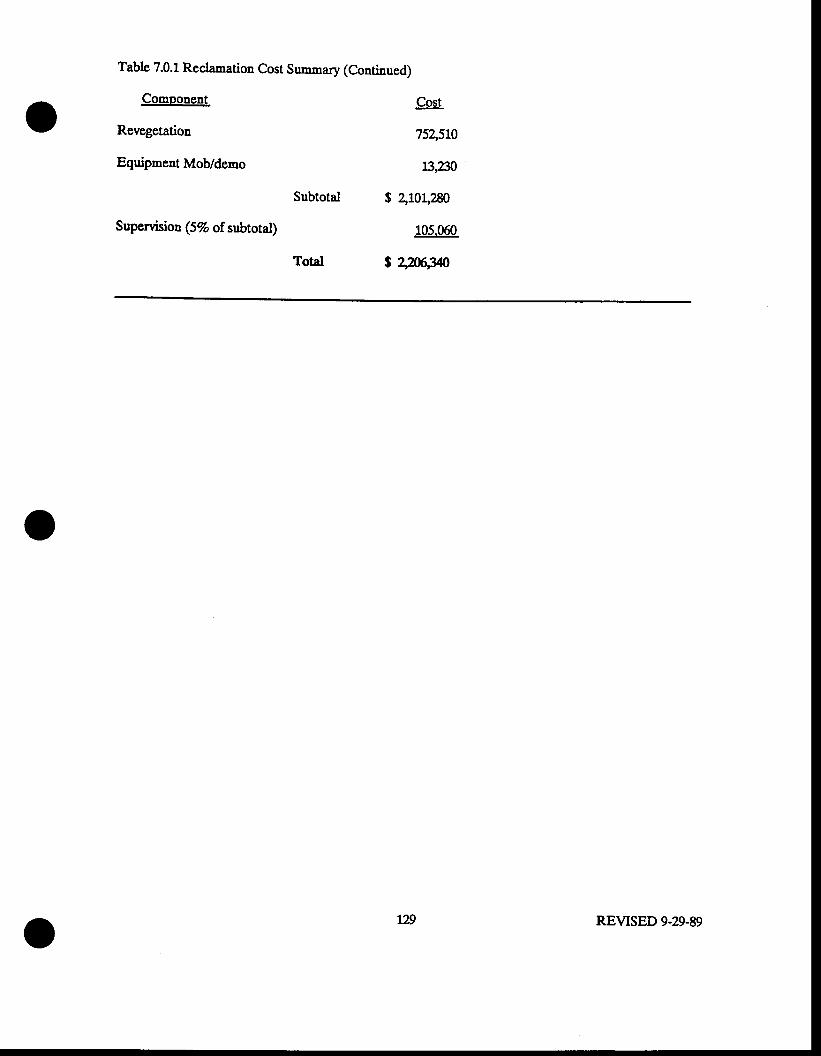
Table 7.0.1 Recl"mation Cost Summary (Continued)
Component
Revegetation
Equipment Mob/demo
Cost
7s4sil0
L3,2n
$ 2,101,280
105.060
j 2wN
Supervision (5% of subtotal)
Total
IE REVISED 9-29-89
8.0 Refcrcnccs
C"ll and Nicholas, 1987, Barnep Canyon and Mel-Co Slope Design Prepared for BP MineralsAmerica
Caterpillar,Inc., 1988. Capterpillar Performance Haadbook, Caterpillar Inc., Peoria,Ill.
P-o & Moore, 1988. Surface Water and Groundwater Assessnent for the Baraeys Canyon GoldProject Sdt kke County, Utab. prepared for Bp Minerals.
Hawking R.H. and K-4. Marshall, 1980. Storm Hydrograph Program, Final Report to the UtahDivision of oil" Gas and Mining. utah State university i.ouoaatioq t,ogao, utal"
National Oceaaic and Atmospheric Administration, LyB. Precipitation - Frequency Atlas of theWestern United States: Volume VI, Utah- NOAA Atlas Z
Sergent, Hauskins & Bechrit\ 1988. Geotechnical Investigations R"porq Heap Leach Padg Barnepcanyon Projecl Salt Lake county, utah. prepared for Bp MLeraIs america.
Scrgent, Hauskins & Bechrit\ 1988. Geotechnical Investigations R"potq Waste Rock Dumps,Baruep Canyon Project, Salt lake Couuty, Utah. Prepared for BF Minerals America.
Soil Conservation Service, 19t2. National Fngrneering Handbook Section IV - Hydrologl.
Soil Consenration Service, 194. Soil Survey of Salt Lake Are4 Utah- U.S. Department ofAgriculture.
!Y^:q AJ-, Compiler, Lns. Geologic Map of &s gingham Disrrict" in Bray, E. R. and Wilson,J.C., eds., Guidebook 1s ths gingham Ml"tqg District Soc. Ein. Geologisq plate i.
Van Haveren, Bruce, P., 1986. Water Resource Measurcments, American Water Works Assog Denver,Co.
Y4a"U KM., Seiler, R!, and DJC Solomon, 1987. Chemical Quality of Ground Water in Salt Lakevalley, utah, 1969 - &5. Tech. pub. No. 99, utahDepartmcnt of Nattual Resourccs.
!V1dde4fU., Seiler, RJ-., Srntini, Melissa, and DJL Solomoq 1987. Ground-Water Conditions inldJ Lake Valley, Utah 1%9-83 and Predicted Effecs of Increased Withdrawals from Wells. Tec,h.Pub. No. 87, Utal Department of Natural Resources.
APPEI{DIXA.I
(CDNFTDETSTAL - BOUND SEPARAIELY)
- -REDACTED- -
ORIGTNAIJ IJOCATED TN DOG}T CONFTDENTIAI' TILE
FIGURE A-I-1
BARNEYS CANYON DEPOSITGENERALIZED GEOLOGIC MAP
AND CROSS SECTION
CONFIDENTIAL
- -REDACTED- -
ORIGINAL LOCATED IN DOGt,t COIIFTDENTIAL FII,E
FIGURE A-T- 2MELCO DEPOSIT
GENERALIZED GEOLOGIC MAPAND CROSS SECTION
CONFIDENTIAL

APFEII{DTXA.tr
GEOII)GIC II)GS OF DRILL HOLES AIiID WELI,S
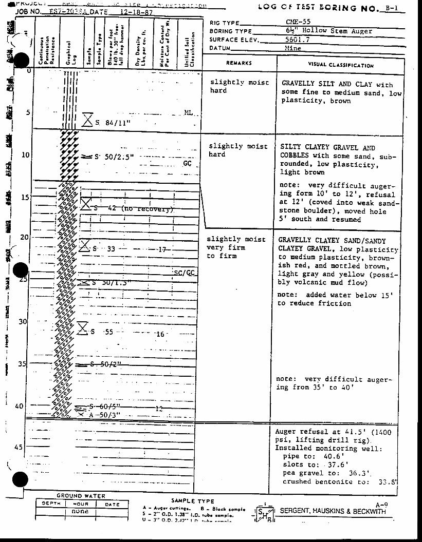
f f K U J g \ - : - - - i r i : i c ; . " - . : . ' . 1 r e I r : . . . , L - . 1 . - r i . C t r
JOB NO.LQG Cf rEs? EOR, ING NO. B-1
Rrc rypE CI'!E-55E O R I N G T Y P Et.
t \
f
1fl
II
{
Id!sII
flII
flII
{
- - S' 5012;5".GQ
III
rl
tigi
It
i
I
S A H P L E T Y P E I
A u g e r r e f u s a l a r 4 1 . 5 r ( i 4 0 0ps i , l i f r ing dr i l l r ig ) .Instal led nonicoi j .ng wel l :
p i p e c o : 4 0 . 6 's l o t s r o : . 3 7 . 6 'p e a g r a v e l t o : 3 6 . 3 ' -c rushed bencon ice co : 3_1. .
A-9SERGENT. HAUSKINS & EECKWITH
r C rr o o
: o c
: : :G C 'o a a
9 A r
_: i3s Eiitti 3 ii ! !
3 sa a
o a- i: i
O J
- ;! r: o
l J oa :i :: Uo ato .
co
o o
1 Sa :
? J: U vtSuAL CLaSst FtcA TtOll
lrIIIII
I s 8L/Lt ,
sl ighcly moisrhard
CRAVELLY SILT AhtD CLAy wic.hsone fi.ne to nediun sand, lowplasr ic i ty, brown
s l igh t ly mo ischard
SILTY CI.AYEY GRAVEL A}:DCOBBLES uit,h some sanci, sub-rounded, low plast ic icy,light brornr
note: very di f f icul t auger-ing fo rn l0 ' to l2 ' , re fusa lat Lzf (coved into weak sand-stone boulder), moved hole5' south and resumed
slighcl-v moiscvery firrnto f irm
GSAVELLY CL{YEY SAIID/SAITDYCLAYEI GRAVEL, low plascici.ryco uediun plasticity, brown-ish red, and Dott led brorcn,l ight gray and yel low (possi-bly volcanic snrd flow)
note: added water below 15 I
to reduce fr ict ion
note : very d i f f i cu l t auger -i n g f r o m 3 5 ' c o i 0 '
.)< A.+0/.3',
suRFAcE e lev . 5601 .7 -DATUM- } I ine
G P O U N D W A T E R
A - Asgcr cunangr. B - Blccl roaplc r[C:7fs - 2" o.D. l .3s'. t .D. robr ronote. - ' lJt+' l .u - 3 " o .D. 2 . r2 . . I n . , , r - . - - - r - i , r ' t sk
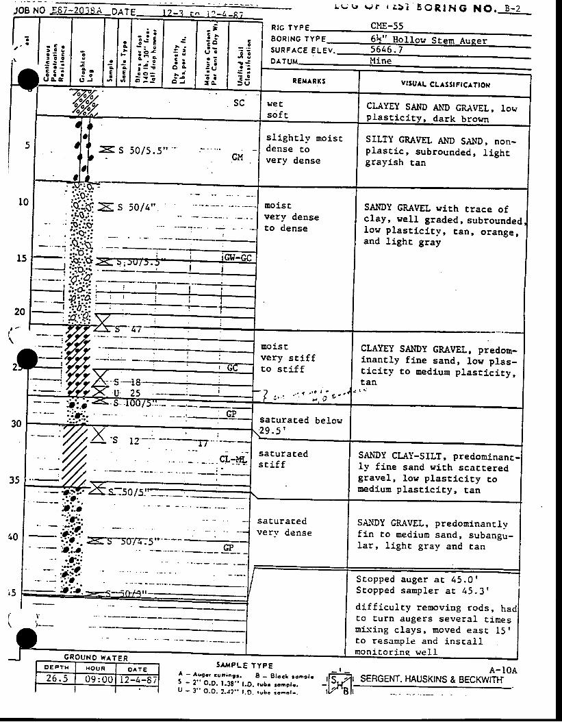
JOE NO
G R O U N o W A T E R
L ( - ( ' ( r r I r 5 t BORIHG NO. B_2
clE-55
ffiffiJ:tD A
S c o p p e d a u g e r a t 4 5 . 0 1S c o p p e d s a m p l e r a t 4 5 . 3 '
di f f iculcy removiug rods, hadEo Eurn augers several Eimesn ix ing c lays , moved easE IS 'co resample anci inscal lmon icor ine we l l
R I G T Y P €
co
o o
! : -a ' :
€ r- - o
: ) g
: 5 to = -l o os::c c .o a a
u c c
fI
SAr,tpLE TypEA - Av9r. cur iagr. B - Slocl roaclr5 - 2" O.D. 1.3g. . t .D. rvbc ronpto.U - 3 " O .O . 2 . J? . . t .D . r ub r r oao t - .
A- IOASERGENT. HAUSKINS & BECKWIT}f!,TMi,
aa
acE0
_! !3 : E- : o
i i ;; 3 i
"r : !
C -a a
o a- i
oo
ca
U
ao. vlsu^L CL SStFtclttox
CLAYEY SAI{D At{D GRAVEL, towplast ic i ty, dark brown
sl ight l ; r rnoiscdense Eovery dense
SILTY GRAVEL AI{D SAND' oon-p lasr ic , subrounded, l ighcgrayish tan
eoistvery denseto dense
SAI{DY GRAVEL wich rrace ofclay, wel l graded, subroundedlow plast ic l t l r , tan, orange,and Light gray
CLAYEY SAI|DY GRAVEL, predom-inantly fine sand, low plas-ciciry to medium plast ic i ty,Ean
noi.stvery sri f fro sr i f f
/ . . { r ' c t l g - .
, a t l . _
, < : i
t : . i .<srcsaturated below' 2 9 . 5 '
s--50/5j'-
sat,uraceds r i f f
SANDY CLIY-SILT, predominanc11r fine sand wj.ch scatteredgravel, lon plascici ty couediun plast ic i ty, tan
saE.uratedvery dense
S&\DY GRAVEL, predominanclvf in to medium sand, s,rbangu-lar, l ight gral ' and tan
o€P tH H O U R O A T E
26 .5 09 :00 L2-4-87rV '8h
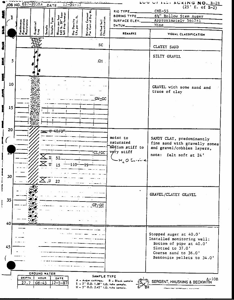
- l l \ v r S v .-JOB pg- 867-2039i. Olr i - l2:6.a-rf L W \ J \ . z l l r r r N O . B - 2 B-
, o f B-2)s ( . . ) X l t i G
( 2 5 ' E
T1li
ia
r t
ar C r
i ! i, 3 0
€ : !C C 'a a a( , a c
o
9 oJ O
( ' J
l i. l :c t q€ t Eo l o
- i !3 s E
:i;i 3 ii :=
C ra a
o sa i
O J
_ t: lE o
r J oa :: -: Ut :- c
co
o €
1 €. : :? l) U
nrc rvpe CME-55EoR|NG rVpesuRFAcE e lev .orruu lt in
REH RKS vtSu^L CL^SStFrCaTtox
5
sc CLAYEY SA,ND
.cltSILTY GMVEL
'.6-
v,.?,
- lo,
l0
l5
itQh-t',:d.C.]i:-q
CRAVEL wich sone sandtrace of c lay
I tol(tlI;I
l,o
II noisr roI sacuracedfur?$iurn sriff ro
rv sEiff
\ H. o S- ..-- ,<.
SAIIDY CLAY, predomJ.nanrlyfine sand L'it,h gravelly zonesand gravel/cobbles 1ayers,
no te : fe l r so f r ac 241
35
40
GRAVEL/CLATEY GRAVEL
45
(
S c o p p e d a u g e r a c 4 0 . 0 'Instal led noniror ing r ,-el l :
B o c t , o m o f p i p e a c 4 0 . 0 'S lo t rec i ro 37 .0 '
C o a r s e s a n d c o 3 5 . 0 'B e n t o n i c e p e l l e r s c o 3 4 . 0 1
S A H P L E T Y P EA - Augr r conangr . I - S lock toap l rS - 2 " O.D. 1 .38 ' . l .D . fubc roae le .U - 3 " O.D. 2 .12" t .D . rubc ioao lc .
_ t _
iffi1sERGENT, HAUsKTNS & BEcKwr+illoB
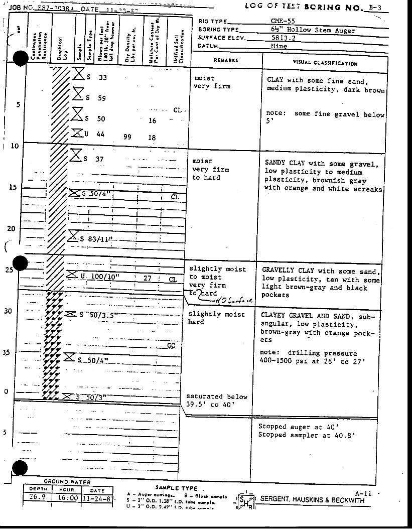
J OB N O.1"9-L.193S..1,_ D
! t t5 = -t c c
: : :c c .o a a
t J G C
- i !t s Ei it-i 3 i.3!!
: !
C sO a
O A
- iO J
_ t5 .? o
lrJ o
a :i :
: e; ;= o .
co
o a
1 Sa ' :
€ r= o= U vtsu^L CLaSStFtcAt tox
T33 . .
59
cL . .50 16
44 gg 18
moiscver]' firn
CLAY with some fine sand,nediun plascici ty, dark bror,rn
noCe: sone f ine gravel below5 '
noistver:/ firnto hard
sl ight l l ' moisrto moistver-\r firmo?rard
--i{c !..{.,c
CRAVELLY CLAy wirh some sand,low plast ic i ty, tan tr i th somelighr brown-gray and blackPockeEs
-11a1-,r1rr-) v t )
sl ighr ly moisEhard
saturaced below3 9 . 5 ' r , o 4 0 t
Scopped auger ac 40 '
S c o p p e d s a m p l e r a E 4 0 . 9 '
LOG Of IE5 ; ECRING NO. B -3
RIG TYPE gME-55q 6 6 . \ t ^ ? v a -BoRING TYPE 61" l tol l - E: AugerSURFACE ELEV.
SANDY CL{Y wirh some gravel,low plastici.ty to mediumplast ic i ty, brocnish grayrith orange and white streaks
u 100
C R O U N D w A T E R
CLAYEY GRAVEL AllD SA-r\D: sub-angular, low plast ic i ty,brown-gray with orange pock-e t s
note: dr i l l ing pressure400-1500 ps i a r 26 I to 27 ,
SERGEI.IT. HAUSKINS A EEC*W#'' I
SAfiPLE TYPE
| - Aogrr curtaag3. I - glocl rooplc
? -
?" O.O. 1.38'. r .O. rubo :onplr.U - 3 " O . D . 2 . . ? . . t . O . , u b - . ^ - - t -
OE PTI { H O U R O ^ T E
: 6 . 9 t 6 : 00 t i-24-8_ t _:,ffi);
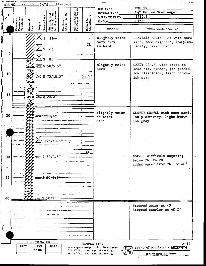
a ' n g J g ! ' -
199 19. ES7- j03bn DATE r l -23 -E7
' ) { 'r C o
3 : :t 3 0
i - . ic c .o a au c s
0
1 o; o
O J
ac€o
aA
ao€o
- i !3s E
:i;i e€i3!
: :- eC -a a
o g> 1
O J
- t5 l? ou oa :: :: U: := c
co
o o
a ' ;. E J3 ( J
p15 lypg CllE-55
BSRING lypE 6:1" Hollow Ste:n Auger
suRFAcE e lev . 5785 .9DATUM } t ine
:{
IIlsIIl ro
l5
20
(l
\:'l"l.'lI
( )
REXARKS vrsu^L cL^ssrFrcATtoN
2*
CL63
o l
slighcly rnoistvery firmco hard
GRA\TELLY SILTY CLAI wich sosresand, some organ ics , lowp las-t i c icy , dark b rown
s l igh t ly mo ischard
SAIIDY GRA\IEL with trace cosome clay binder, Bap graded,low plascicic.v, l ight brown-ish gray
50 /3 .5 "
slighcly aroistto uoisthard
CLAYEY GRAI/EL sith soue sand,low plasticicy' light brorlrt-ish gray
noce: d i f f i cu l t auger ingb e l o w 2 6 ' t o 2 8 'addec r raEe: f rom 26 ' to 40 '
Scopped auger ac 40 'S c o p p e d s a a p l e r a c 4 0 . 3 '
G E O U N D W A T E RSATiPLE TYPE
A - Ag9rr suning3. B - Blocl rcoglrS - 2" O.D. 1.38" t .p. rubc rooolr .U - 3" O.D. : .42" l .D. tube ronolc.
A-12SERGENT. HAUSKINS & BECKWITH
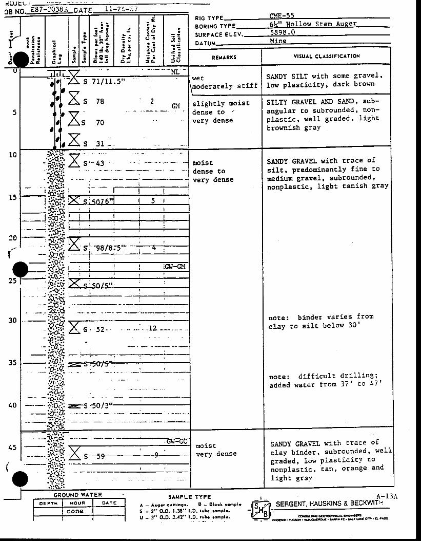
r((JJEL t
ce xo._Eg-t:038n orTE = t!;?.i:iZcuE-55
f'' r€iiai;
o
39 o: o
O J
aAEo
ac
aAEo
:iii i ;i 4€; : !
2 )- g3 :a a
o .- i; i
O J
_=3 .E o
( J l oC ?: a: e; :J O .
Cc
o o
€ r
: JJ 9
R tG TYPE , LNT , - JJ
BoRtNG tvpE 5k" Hollow Stem Auger
suRFAcE euev . 5898 '0DATUu Mine
R€rt^RX5 vrsulL cLAsslFlcATloN
5
t0
-1 i l ;v ' ' - - - - - - I rL ' -
lJEE
lraoderatel)' stiffSANDY SILT wich some gravel,
low plast ic i tY, dark brownA s z i r t t .s"
X, za , *,vAs 70
vA- s 3r - .
s l ighc ly mo is tdense tover.v dense
SILTY GMVEL A!(D SAIID, sub-
angular to subrounded, non-p lasc ic , we l l g raded, l igh t
brownish gra-v
;t 'i r l l l
'.'rttsi:
*ii:X
rci.stdense tovery dense
SAIIDY GRAVEL with trace of
silt, predorninanclY fine to
medium gravel, subrounded,nonplascic, Iigbc tanish graY
note: binder var ies from
c lay co s i l r be low 30 '
no te : d i f f i cu l t d r i l l i ng ;a d d e d w a c e r f r o n 3 7 ' t o 4 7 '
l ) '.1#FFiurr 5a
:0
I
ffi
30
35
40
l'
I2s lE
- -
45
I
l:-It - - - - -
)-
moiscvery dense
SAbIDY GMVEL wich trace of
clay binder, subrounded, wel l
graded, Iow Plast ic icY co
nonplascic, lan, orange and
l ighc gray
cRouNo wATER .. sAmPL TYPE , A -13
A - A!9t cut lang. . I - Blocl :cmPb
S - 2" O.D. 1.38" l.D. rubc rcnpb.U - 3" O.D.2.{2" l .D. rgbr rcnple.
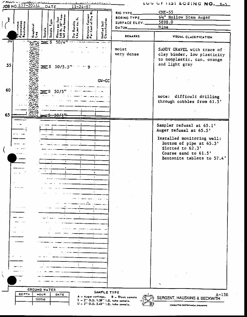
- - K I J J ! - ,
.log xo.:37:?91:A -o^t. rr-za-s; =_-- L 9 , r u t i i , 5 1 B ( ) i l i l G N O . n _ s
r SERGENT, HAUSKTNS & BECKwtfr-l3BSA^{PLE TYPE
I - Ag9or €unaa9.. I - Elocl tono[5 - 2" O.O. 1.38" t .O. rgbc rone|r .U - 3" O.O. 2. / t2" t .D. rubc goaelc.
i l
i t ; !g\ r o o
- : : .c
3l o- o
( ' J
acEo
aA
JaEo
_: i3 s I
:ii; 3 ii :=
: t
C -a a
o 4; i
A J
_ -3 l: ou t oo ?: -: ui a= o .
3o
o o
a :S e
? JD|J
ps6 lyps Cl4-55BoRtNG 1yp6 6k" Hol low Steur AugerS U R F A C E E L E V .Dltuu lline
C 'a a
c c R€xAnxs vlsu^L CLaSSrFlcATtox
55
60
65
so l4
s0 /5 .5 '
moistvery dense
SAI.IDY GRAVEL wich crace ofclay bi .nder, low plascici tyto nonplast ic, canr orangeand l ight gray
note: di f f icul t dr i l l ingth rough cobb les f rosr 61 .5 '
(
f:
Sanpler refusal at 65. I I
Auger refusal ac 65.51
Installed uonitoring well:B o c t o m o f p i p e a t 6 5 . 3 1S l o c t e d t o 6 2 . 3 'C o a r s e s a n d t o 6 1 . 5 'Benton i te tab le ts to 57 .4 '
CHmG€otO*a C.G{€B
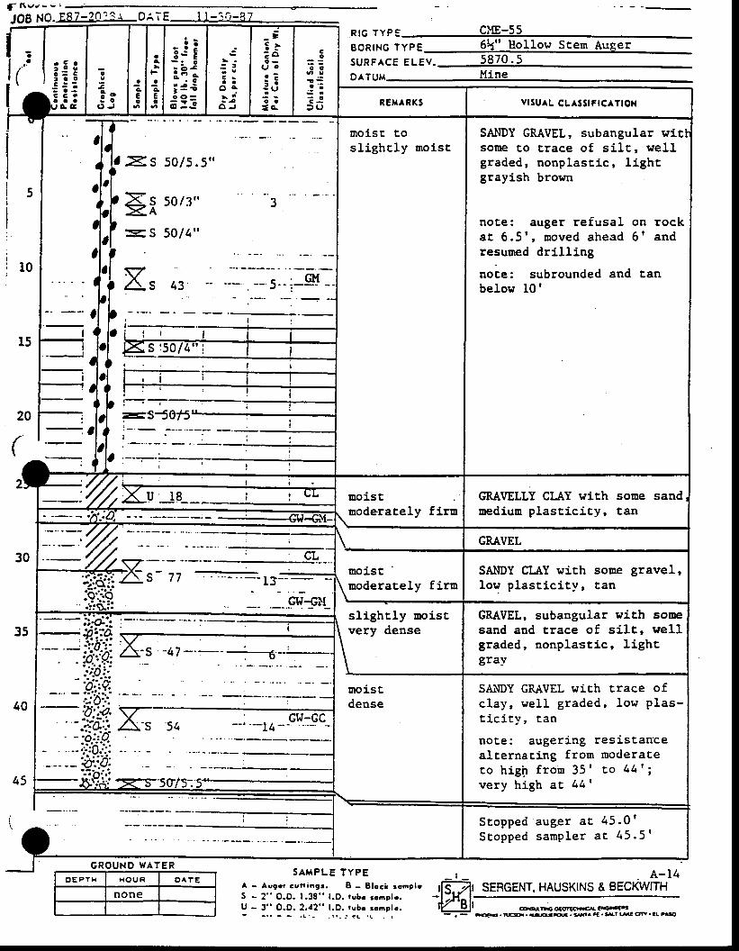
f , t s J - - |
aa
t
JOB NO. E87-2o?3r O; , ;E I l - _10 -3 7
a: s 50 /5 .5 , '
trt so/3": s 50 /4 "
X'
G R O U N D W A T E R
O E P T H H O U R O ^ T E
none
a,ot
!
€o
o o
a ' :€ r
: J: ( J
g .
a o
c -a a
A C
n tc r vp :BoRTNG lypg 6k" Hollow Scern Augers u R F A c E e l e v . 5 8 7 0 . 5DATUM UiNE
43
S A H P L E T Y P EA - Asgoc cvt l iagr . I - Slocl :cnole5 - 2" O.O. 1.38" l .D. robr rcnplr .U - 3" O.O. 2.a2" l .D. rubr romolc.t - . t - - . L . - - t r - j ? t . ! t
aa
aAEo
E j ii i;; = €; : !
C ra a
o aa 4
6 J
_ =5 .E o
(.it o
a - -: :: e? i: o . REH^RK5 vrSuAL CL SStFtCATtOll
moisc t,osl ighcly moist
SAI'IDY GRAVEL, subangular witsome to Crace of s1lC, wel lgraded, nonplast ic, l ightgrayish brown
noce: auger refusal on rockat 6 .5 ' , noved ahegd 6 t andresuned drill ing
note: subrounded and tanbelow l0 '
.:-i l . l e GRAVELLY CI.AY wlCh
nediun plast ic i ty,some sandtan
L D t tmoi.stmoderat,ely firn
SAl.lDY CLAY with some gravel,low plast ic i ty, tan
slighcly moi.stvery dense
GRAVEL, subangular with somesand and trace of silt, wellgraded, nonplastic, lighcgray
Stu\DY GRAVEL wich crace ofc lay , we l l g raded ' low p las-t i c i t y , tan
note: augerj .ng resistancealternacing frorn moderaE,ec o h i g h f r o n 3 5 ' E o 4 4 ' ;very high aE 441
Stopped auger a t 45 .0rS t o p p e d s a m p l e r a t 4 5 . 5 1
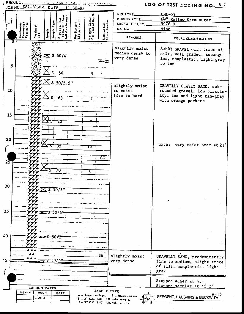
o E P T H I x o u n O A T E
noneI
SATPLE TYPEA - Augr r cs r ing t . 8 - B loch rono lcS - 2" O.D. 1.38" l.D. rubc rcncle.U - 3 " O . O . 2 . ! 2 " l . D . r u b . r a - - r .
tOG OF TTST gCRIHG NO. B -7
SERGENT. HAUSKINS & BECKI^f#5
('l;:g.jjj
o
; oJ O
( , J
l : .t >l F
a l .c l aE t €o t o
- i !t s E
i itt; = i
; : =
3 -a t
o aa i
O J
_ t3 t: ou o. 7i :: Ut :=c.
Co
o o
! €a ' :
: J= U
Ptc TYP F er,fF-q q
B O R T N G ' ' "
S U R F A C E E t . ' U .
DATUM I\TiNE
RE,{ARKS YTSUAL CLlSStFtcATtox
5
-:Fr--
i?..i.s' a'.-.I-
$:i:g >< s 5o/4"tt'O:'. GW-CttF::-t:;i$.i: vjqi,gAs s6 s
sl ighcly moi.srmedium dense Covery dense
SANDY GRAVEL sirh crace ofs1l t , wel l graded, subangu-la r , nonp las t ic , I igh t g rayto tan
' ffiXs so/s.s,'sl ieht ly moist GRA\'ELLT CLAYEY SAND srrhto moistf i ru to hard
rounded gravel, lou plascic-i ty, tan and l ighr tan-graywith orange pockets
20
(
Tnote: very moist a r 2 l '
40
r5
(
- o o co o :
.s l igh t ly no iscvery dense
GRAVELL:- SAI{D, predominanclyf ine to medium, sl ighc E,raceo f s i l r , n o n p l a s E i c , l i g h rgray
G R O U N O W A T E R
S E o p p e d a u g e r a r 4 5 'S c o o n e d s a m o l e r a c 4 5 . 3 '
t,W
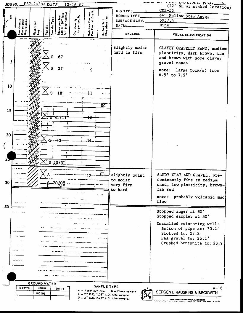
Jo8 NO. E87-20jSA D,ATE- - v v . . - - .
( 22 ' -:i' ^_r nB \r t\l \J o -- -Nr or sE,aked locacion)
('l-
: 5 :t o o
: : :< c .o a a
u G c
! l .
"t; 13
ac
aAEo
i i ;:i"ii =€i : t
C -a a
o c- | is i
O J
- ;5 .E ou oa :: a: U; a=c.
Co
o e
a i ia ' :
: o
D U
Rtc rYPE cME_55E O R I N G T Y P E
S U R F A C E E L E V .
Drruu )tine
REXARXS v6uAL CL.rSsrFtc.rTtox
t0
l5sc
sl ighr ly moischard co firra
CLAYEY GR"IVELLY SAl,tD, mediusrplascici ty, dark brorrn, tanand browr with some clavevgravel zones
not,e: large rock(s) frour6 . 5 ' r o 7 . 5 '
20
(
t t l
:
F
:/%oZot \ S _5
30
slightly moisrto trois8very firrato hard
SAI{DY CI-AY AIID GMVEL, PTe-doninantly fine to nediugrsand, low plast ic i ty, brown-
red
note: probabllr volcanic oudflowt
I-J J
I
Scopped auger at 301Scopped sarnpler at 30'
Instal led noincoring wel l :Bo t to rn o f p ipe a t : 30 .2 '
S l o c t e d ' t o z
2 7 . 2 'P e a g r a v e l t o : . 2 6 . L 'C r u s h e d b e n c o n i E e r o : 2 3 . 9 '
SAI{PLE TYPEA - Aggcr cun ing3. I - B loc l ronp l rS - 2" O.O. 1.3S" l.D. rube ronolr.U - 3 " O . D . 2 . ! 2 " l . D . r u b r . r c a s l r .
A-16SERGENT. HAUSKINS & BECKWITH
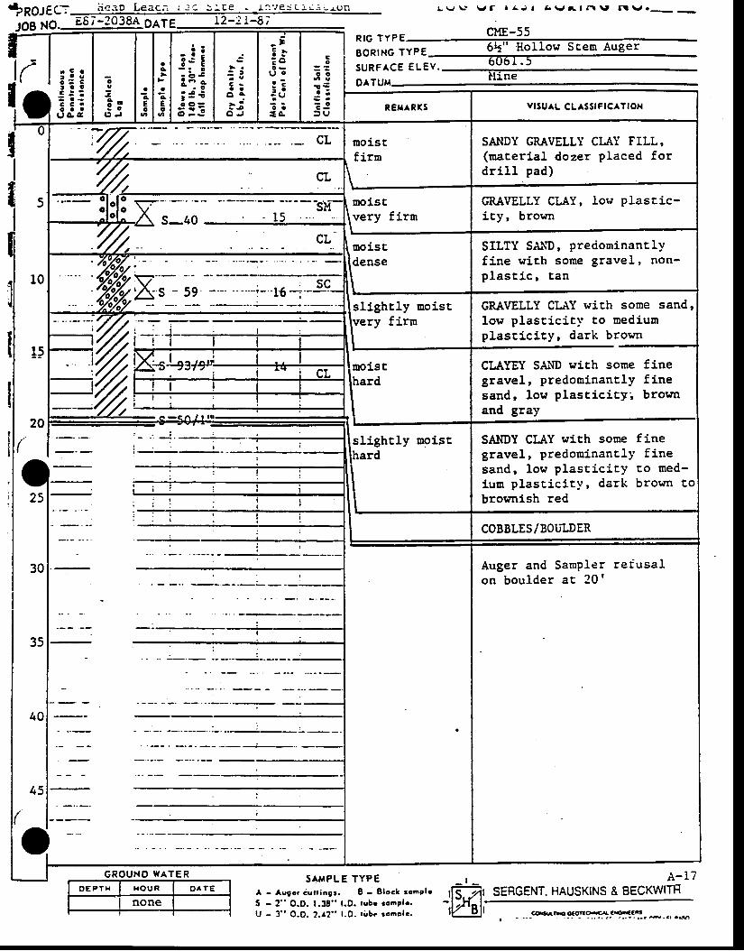
- i !3 c E
ii;; 4 €i :=
: !C ra a
o A- a 'a - j
O J
_ =5 .: ou oa ?: a: ( J
r iI O .
SAI.IDY GRAVELLY CLAY FILL,(rnaceri.al dozer placed fordr i l l pad)
moistfirn%noistvery fir$l
GMVELLY CLAY, Iow Plascic-icy, brown
rtroistdense
SILTY SAliD, preciorninantlYf ine wich some gravel, non-p las t ic r !3o
sl ight ly Doist GRAVELLY CLr\Y with some sand,low plast ic ic l ' co mediumplast lc i ty, dark brown
CLAYEY SA,r\D with some finegravel, predoninantly finesand, low plascicity'' brownand gray
SANDY CIAY with some finegravel, predomJ.nancly finesand, low plasciciry co med-iun plast ic i ty, dark brown tobrownish red
Tslightly noist
COBBLES/BOULDER
Auger andon boulder
Sampler re fusa la t 2 0 r
G R O U N O W A T E R
O E P T H H O U R O A t E
none
SAUPLE TYPEA - Asocr dur iagr. B - Bloc& ronPleS - 2" O.D. 1.38" l .D. tubr rcaglr .U - 3" O.o. 2. t2" l .D. t i rbc ronclc.
A - I 7SERGENT. HAUSKINS & BECKWITH
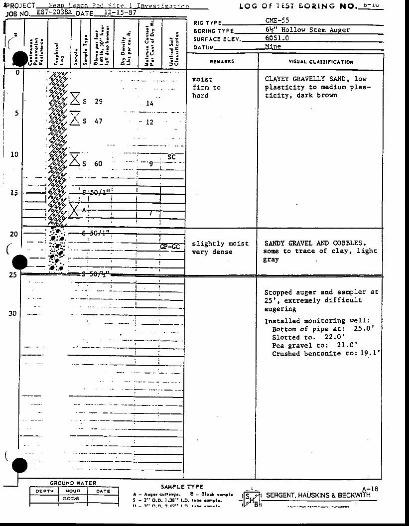
f f t Q J f f J F e a o r e a c h " . c q ' r e I T n v e s : ; o ' " . , . n
1gg ;19. E87-2038A p116 t2-I5-87t Q G O f ] 8 , 5 I E O T , I N G N O . D - l U
l_ll( l::rI'ri:;
o
3* o; o
O J
ac€o
aG
tA€o
- i !t s E
:i;; f €
r r :3
C -a a
o c- r ': - j
O J
_=E}E ou c
c - -: a: U? ar 4
ao
o 6
! sa ;
S r? Jt u
Rtc rYPE cl IE-55
BoRtNG lypg 6k" Hol low Stern Augers u R F A c E e u e v . 6 0 5 1 ; 0oATuM ---, ---,-- irle
REH RKS vrSu^L cL^sstFtcATtox
5
t0
li
20
(
(
t s
\ 7
Z\.:;
A. 47
/ \s
moiscf irrahard
t oCI-AYEY GRAVELLY SAlfD, lowplasticity co nedium plas-Elcity, dark brown
sl ight ly moi,stvery dense
SAI{DY GRAVEL A}ID COBBLES,sotre to ttace of clay, lighcgray
30
{\ t .
Stopped auger and saupler at25' , extreuely di f f icul taugering
InstalLed monitoring weII:B o t c o n o f p i p e a c : 2 5 . O 'S lo t ted co . 22 .O 'P e a g r a v e l t o : 2 1 . 0 'Crushed benton i te co : 19 . l '
G R O U N O W A T E R
O E P T H I H O U R I O ^ T E
none
S^HPLE TYPEA - Asgr r cuna693. B - B loc l 3ong leS - 2" O.D. 1.38" t.D. robe ronplo.t t - 1 " l ' . | i . 1 . t ' r " I n i r .h - . . - - r -
- r - - A - I 8tls7t SERGENT, HAUSKTNS & BECKWTTH-,Wel
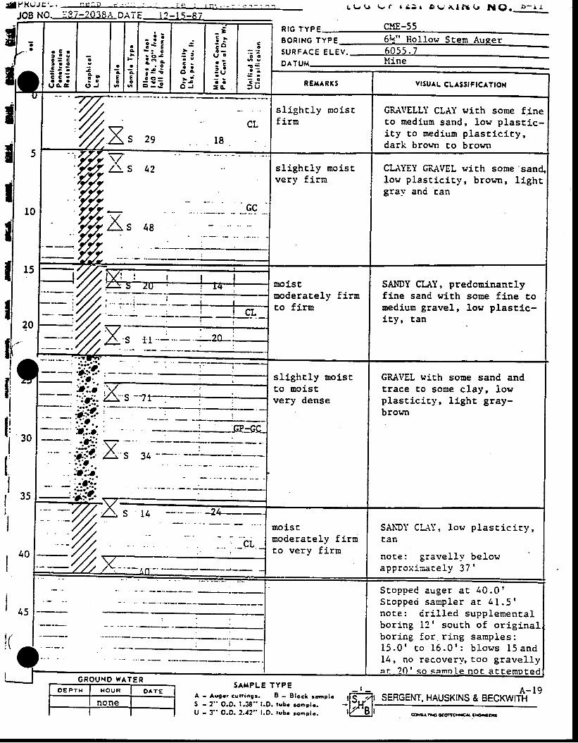
{ l t /KuJtr ' - .JOB NO.--9J:?03.8I.-DATE i2-1s-87
L t r t r \ . r r a : t D t - ' X l a t ( . r N ( ) . D - r r
SERGENT. HAUSKINS &A - 1 9
BECKWITH
S A H P L E T Y P E _ r _
A - Avgor curingr. B - Elock romplc ffq-,)ltS - 2" O.O. 1.38" l .D. tvbr rcoelr . - l - . ) {^ l :U - 3" O.D. 2.12" l .D. tubc roaslc. lY Ol l
,L,ro
r C r! o a
t c o
: : !C C .o a au c c
o
I
* o. o
O J
l t. l :c l eE I Ec t o
iiili:i : ! I i i
_ =5 tE o
Q ' Or ?: :: U? :=c ,
Co
o o
a ' :
: :' U
R I G T Y P E
EoRrNG rV"esuRFACE eUev.oaruu
REXARTS vrsuAL CLASS| FtCATtOt{
5
l0
t5
?o
%x, CL) a t o
a 9
s l ighc ly mo isEfirn
GRAIIELLI CLAY wich some flneto mediun sand, low plasci .c-i ty Eo uredium plast ic i ty,dark brown Eo brovn
GC
48
s l igh t ly mo iscvery fj.rm
CLAYEY GRAVEL with some'san4low p lasc ic icy , b rown, l ighrgral' anci can
moistooderately firnto firn
SAIIDY CIAY, predominanrlyfine sani with some fine tomediuo gravel, low plastic-i ty, tan
ilIIri,,llIl ' 3si
II
loo
lo,
slighcly rnoistto Eoistvery dense
GRA\IEL wich some sand andt,race to sotre clay, lowplascicic_v, l ight gray-brown
-' --7/t {'' s ta
%_%,r:
moiscmoderately f i rnto very fi.rn
SANDY CLAY, low plascicicy,tan
not ,e : g rave l l y be lowapprox iaace ly 37 '
: i
S t o p p e C a u g e r a c 4 0 . 0 'S c o p p e d s a u p l e r a c 4 I . 5 rnoEe: <ir i l led supplementalboring 12 | sourh of or iginalboring for. r ing samples:1 5 . 0 ' c o 1 6 . 0 ' : b l o w s 1 5 a n d14, no recovery, too gravel lya t 20 t so samnle no t ac temDted
G R O U X O W A T E R
CO.rl Ea cf GtrCCa..cA lg:€r3
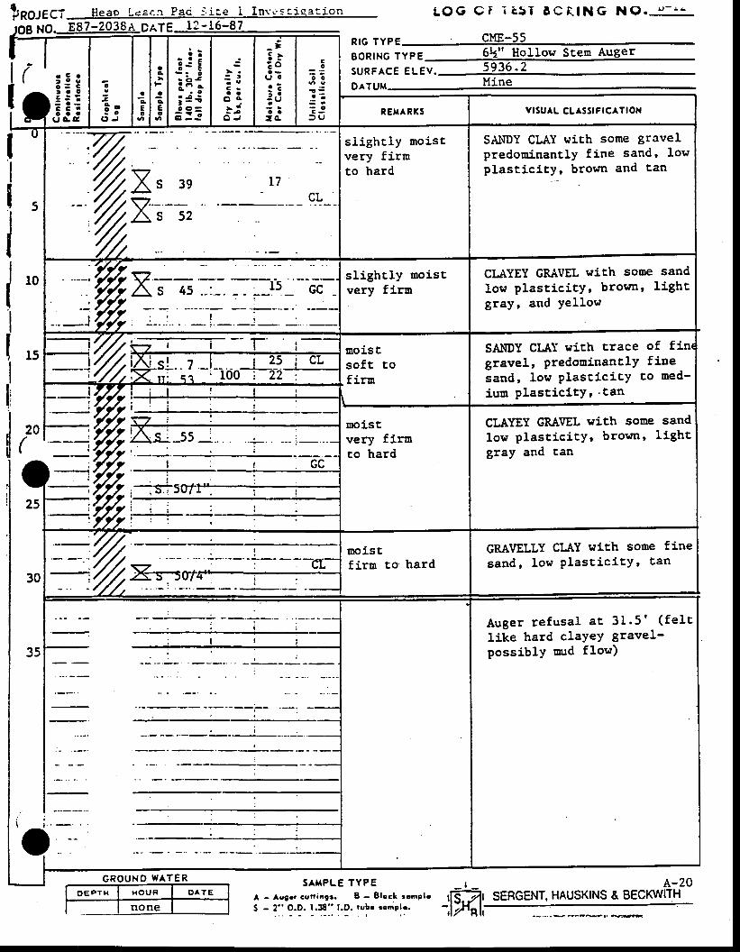
t.r,ROJECT Heao Leac-n Pac : - . !c ,e I Invt 'sc iqa! lq-n
O*_-Eg7-2038A-DATE 12-15-87
A - Acar r cur iagr . B - E lcc l romPlo
S - 2 " O.D. 1 .38" t .D . rubr romple .
LOg Cr r r5 r t cE lNG N0.s1_
_ t _ A.:SERGENT. HAUSKINS & BECKWITH
NR I G T Y P E
BoRING lypE 6L" Hol low Stem Auger
SURFACE ELEV.orruu
( : i !
tj:io
Z9 o; o
( , J
a4Eo
ac
Jg
E!
i j i;i;i 4 ii :5
: t
C ra a
o c- | jL - j
O J
_ t5 rzou oo ?i -: Uo a
: a
Co
o o
a ' :
= O
> U RE'TARXS VISUAL CL SSIFICATION
5
t0
t5
20(
25
30
35
f,r 3esz-- --.As s2
L7- a t
v g
sl ighcly moistvery firmto hard
SAI{DY CLAY uich some gravelpredominantly fine sand, lowplast ic ic] , brown and tan
sl ighcly moistvery firu
CIAYEY GRIIVEL with sone sand
low plast ic i ty, brown, I ightgray, and yellow
12.-W.Xias : ls cc
_im7/t- r r moist
soft tofiru
SAI{DY CLAT with crace of finrgravel, predouinancly fiDe
sand, Iow plasticicY to med-
ium p las t ic i tY ' . tan%P+ri -!-'ooj41,2,
!
I
' ;t : 7*
moistvery firuto hard
CLAYEY GRAVEL rrith some sand
low plast ic i tY, brown, l ightgray and tan
: lelr
noisrfirru to hard
GRAVELLY CLAY with some fine
sand, low p las t ic i tY ' tan
Auger refusal ac 31.5 ' ( fe l tlike hard cIaYeY gravel-possiblY mrd flow)
sAi lPLE TYPE -20G R O U N O W A T E R
:,Ifri,
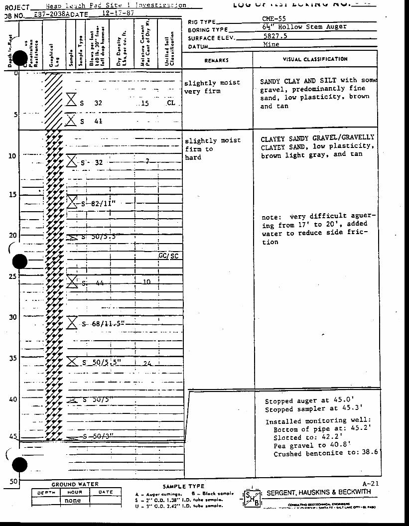
R O J E C T S e a D L c : i ; h F a c S i E c I i n v e s E r e : : : o n
lB XO. aE7-2038AC.rtE 12- !?-i ]7
o E P r H l x o u n I o ^ t E
none
L U ( J ' \ r r . ! > l t i \ / \ l 3 r v a t v o 3
cME-55
A - Augrr cunangt. B - Block ronelc {Sr j SERGENT. HAUSKINS & BECKWTTHt,wiu
GOanDOo:OFSO.-a cro-c€--+. . l Jaea*. 5^.C. 3t WC CR.€, l .Sat
S - 2" O.D. 1.38" l.p. rube rcap|r.
7-'t
1r ;!!
3r;:0
9 o- a
O J
Jc€e
aI
aAEc
_: !t s E;i;i 3€; :=
: iC ra a
o c- di i
O J
- :E }; ot l oo ?i :: U: a:o .
Co
o o
a ' :
? l3 9
RtG TYPE " i . i - "
BoRtNG lypg 6N" Hol lo l t Scen Auger
s u R F ^ C E E L E V . 5 8 2 7 - 5
9A1gM )line
REf .ARXS vlsuAL cLASslFlcATlox
sl ight lY moistvery firm
SANDY CIAY Al{D SILT with some
gravel' PredotrinanBly fine
sand' low Plast ic i tY, brown
and Ean
10
r5
20
(
25
30
35
40
4
(
50
s 32
'Ult 4L
sl ight lY moisEfirm tohard
CI.AIEY SAI{DT GRAVEL/GMVELLTCI"A,YEY SAI{D, low PlasticitY,browa lighc $ralr and tan
noEe: verY difficulc aguer-
ing f roa 17 ' to 20t , addedr"ier to reduce side fric-gion
/.2/-i ,'y'y't V .: '.1 r n I','t/1./-m'
+%;" --n,'-- -7/r
S c o p p e d a u g e r a c 4 5 ' 0 '
S topped samPler a t 45 ' 3 '
Instal led monitor ing wel l :
B o c t o m o f P i P e a t : 4 5 ' 2 '
S l o c t e d c o : 4 2 - 2 'P e a g r a v e l t o 4 0 ' 8 q
Crushed bencon i te so : 38 '6
G R O U N D W A T E R SAtrPL TYPE r A -2 I
u - 3" o.o. 2.r2" t.D. t"ir t.-or.. lreJl
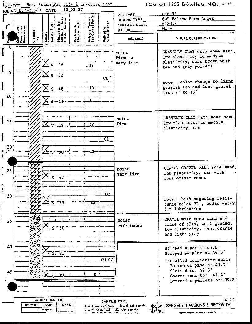
l*ortct' LCG C t 7E5 i BC t IHG NO. b - r ' +
cYE-s5IOB NO*Ed7-2038a DATE 1242-87
O € P T H H O U R OA?E
noneSERGENT. HAUSKINS & BECKWITH
i^i€:f
c
3* r: a
c , J
ag
Eo
ac
aA€o
-a!3sE-ii;
; 3 €i :=
C -a a
o aa - j
O J
- ;: .E ou l oa - -i :: U? i= o .
Co
o !
S o
E JD 9
RIG TYPE LXI . -T)
BoRlNc TvpE 6Lr" Hol low Scen Auger
sURFACE eUev.palgg lline
Io
c .a a
a gR E T A R X 5 . YISUAL CL^SSIFICATIOX
IIII
30
0
5
10
25
35
40
45
l5
20('
I
moistfiru covery firm
GMVELLY CLAY wich some sand
low plasticicY to mediumplascic5.tY, dark brown with
tan and gral ' Pockets
note: color change co l ignt
grayish tan and less gravel
f ro ra 7 t Eo 13 '
26 . I7X'X,t 32 cL.I
)! s 48 :- -
. .- - ro'-:-. -
t.%moistflrn
GMVELLY CLrIY wich some sand
low plasticic-v Eo nediumplasc ic i tJ r Ean
uoistvery firn
CI-AYEY GRIJEL wich some sand
low p las t ic i tY , tan w i th
some orange zones
noce: high augeri 'ng rgsis-
tance belos 35' , added water
for lubr icasion
moist,very dense
- GRA\IEL ryich sooe sand and
ttace of c1a1', wel l graded'
low p las t ic icY ' can ' o range
and lighc gral'
P. . tg l ; : :
S E o p p e c i a u g e r a c 4 5 . 0 '
S t o p p e d s a m P l e r a t 4 6 ' 5 '
Inscal led ooniror ing weI l :
B o c t o n o f P i P e a c 4 5 ' 5 '
S l o c t - e C r o : 4 2 . 5 '
C o a r s e s a n d E o : 4 l ' 4 '
Bencon i te Pe l lecs ag : 39 '8.i':. 7'rg+--r
GROUNO WATER N-22sAi lPLE TYPEA - Avgrr curi .gr. B - Elocl roaplr lE' jJS - 2" O.D. 1.38" l.D. robr rcnplc. -,l.y''li. . - . . ^ A . . a . . l h . . , t - . - _ _ l - t v g t l GTEGX''EO'GA C|...CTS
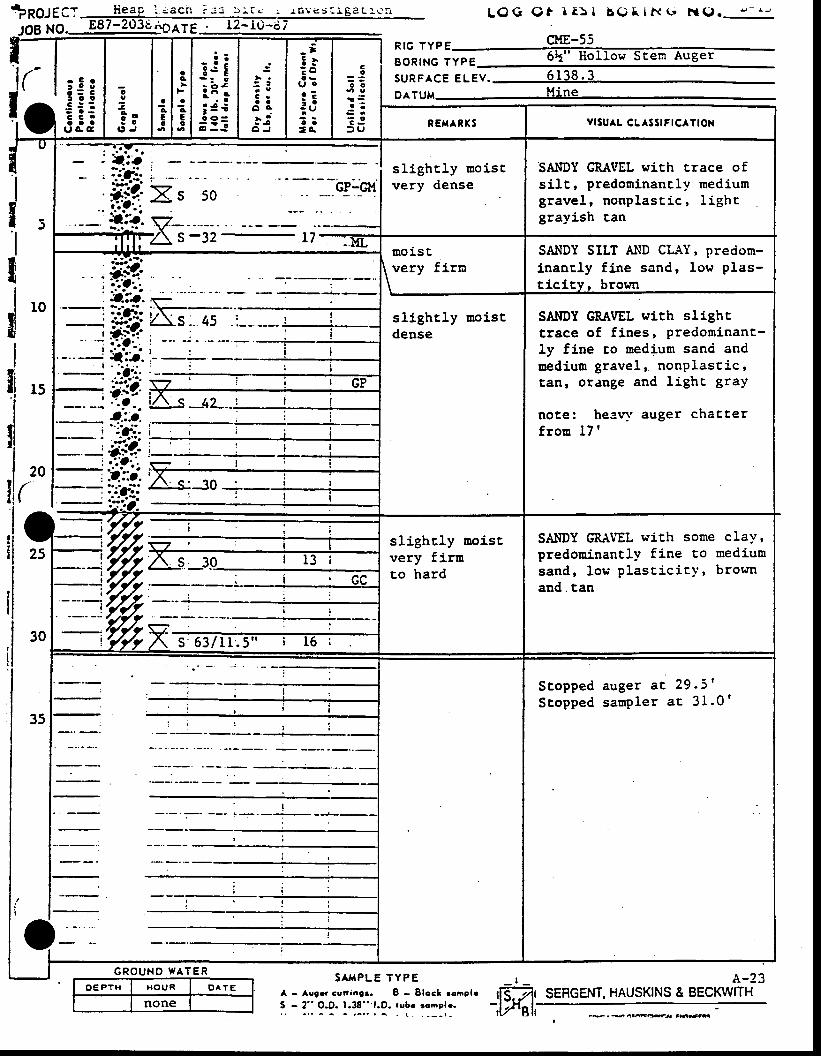
* p O t E C l l i e a p i . = a c n i . : : 5 : . r . : r s v e s i J , g d L l v \ nr n v J b v
y6g 1q9. 887-203u.lOay6 . l2-I0-tl7
O E P T H H O U R D ^ T E
none
S A , { P L E T Y P E . _ r _A - Asga GU6r6e 3 . B - S loc l rompie {A l
:. - i::9-9. 1.T:::.?.:"f-::::l:. -,wel,
L O G Q t r & > l E ( ) t i t ( G l r a g . ! - r J
A-23SERGENT. HAUSKINS & BECKWITH
tiitiI
l lt l
. a - - a v - v a
{;
; 53t g o
i : :C C 'o a a
u G a
o
a1 o: o
O J
ac€o
ac
aAEo
: j i:iii 4€;3!
C ra a
o a- it - j
O J
_ t: t? o
l J oa ?: -: Uo a= c
co
o o
S r
T J= U
R I G T Y P E -
8 O R I N G " "S u R F A C E E L E V . 6 1 3 8 . 3
DATUM
REHARI (S v l tU^L CL SStFICATION
J
I!
10
I
l5
20(
I
: t : i ; -
,#i!{,_*'"v^
sl ight ly moistvery dense
SAIIDY GRAI'EL with trace ofsi.lt, predoninancly rnediumgravel, nonplascic, l ighrgrayish tan
a \ D ) z L tmoiscvery firn
SAl.lDY SILT AND CL{T ' predom-inanrly fine sand, low plas-t ic i ty, broun
sl ight ly noistdense
SANDY GRAVEL ttith slighEtrace of f ines, predominant-ly flne to nedium sanci anduediun gravel, . nonPlascic 'Ean, orange and lighc graY
note: heeq' auger chaEt,erf ron 17 '
:-3O
I ,ryJJ
. l
slighcly moistvery firnto hard
SAI{DY GS.IYEL with sorne claY 'predorainantly fine to mediumsand, 1or, ' p last ic i t .v, brownand. tan
,JJIz)
30
35
I
aI
i
I
'ffi:3-Q I3
;
StoppedStopped
auger a t 29 .5 's a m p l e r a E 3 1 . 0 '
G R O U N O W A T E R
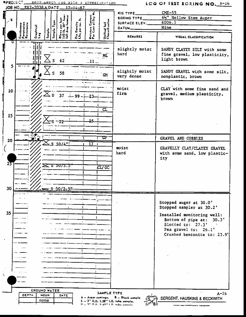
rPRO ' : i -T he3. , . / -eacn r ' i iO b : - :e r I rvesC iss : . ] .On t cc o f IEST EcRtNG NO. t s - r6JOB NC._E8-Z4S8ADATE | ?_r6_87
''-' | ;: coj;i
o
at o: o
O J
ac€o
ac
aq
€o
- : !3-- E:i;; 4 +d:=
: t
C -a a
o a
r iO J
-.;: .E ou | .c 7i :: Uo a= s
Co
c o
! sa ' :
S .? Jt u
p16 1yp6 CME-55E o R r N G r V e esuRFAcE euev . 6006. IDATUM Mine
RET^RXS vtsu^L cLAsStFtCATtOX
Il lt l
Il lt i
t - -I;V . -YLiAs 62 - l l - -
sl ight ly moisrhard
SAIIDY CLAYEY SILT wi.th sonef ine gravel, low plast ic icy,light brown
5
10
l5
20
(
2
o{sl ight ly sroiscvery dense
SAIIDY GRAVEL stch some silr,nonplastic, brown
moiscfirn
CLAY wich sone fine sand andgravel, oedium plasticlty,brown
GRAVEL A}ID COBBI.ES--j //t '-s.5o/-4j: i____L-:Ll
r--- '/ l :uoisthard
GMVELLY CI.AY/CI.AYEX GMVELwith sone sand, 1ow plascic-ity
30 =r=,
35
Stopped auger a t 30 .0rScopped sanpler ar 30.2'
Installed nonitoring well:B o t t o m o f p i p e a r : 3 0 . 3 tS l o t t e d r o : 2 7 . 3 'Pea grave l to : 26 .L 'Crushed bencon ice co : 23 .9 '
G R O U N D W A T E RsAI{PLE TYPE
A - Avger cuat ia l t . 8 - Elccl rcnelrS - 2" O.D. 1.38" l.D. rube roaote.l r - " . . O i 1 t 7 . . I n r f i h . < a a r t - -
' .^-2+SERGENT, HAUSKINS & BECKWITH
_ t _ffiI l n o n e I I-
t,ffi|,
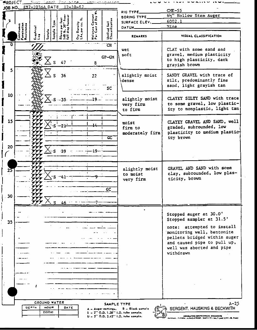
l Q Q J f f T L ' . . . ; . , r r i r ' = . ' ' , - r e I r n " . - ' - ' 1 . . . n r
JOE NOt v v v l . r - . - Y 6 a a t v a ! v . : -
55
t*:;c9 o: o
O J
acEo
!A
aAEo
- : ;3s E
:i;; r€; : =
: t
C -a a
o e: i
O J
- t3 :; ou oa ?: -- Lil
o a= A
Go
o o
1 Sr ' l
: J> U
RIG TYPEBORTNG lypg 6k" Ho11ow Stem Auger
suRFACE eUev .DATUM-YI
REXARKS vrsuaL cLAsstFrcATloN
IIl5IIItoIIl t tIIl tol(j!I
30
35
,rr' "cH -weE,so f t
CLAI wich some sand andgravel, medium plascici tyto high plascj .c i ty, darkgrayish brorm
:ilt-..ii*:'j <z GP-GM
nr''. \./
ip i .As 47 8
I
\ s l ight ly noist\dense
\
SANDY GRAVEL wirh crace ofsi l t , predominantl l ' f inesand, Iighc grayi.sh tan
slightly moist,very firm
uolstfiru tonoderacely fira
CLAYEY SILTT SAI{D with traceto sone gravel, low Plastic-icy to nonplastic, lighc tan
CLAYET GRAVEL AND SAIID, wellgraded, subrounded' lowplastici.cy co oediun Plasticity brown
/o7j1 I :
slightly uoistto Doistvery firu
CRAVEL AIID SAI{D ttit'h soneclay, subrounded' low Plas-t ic i ty, brown
Scopped auger ac 30 .0 'Stopped saurpler ac 3I .5 '
noEe: atcempced to instal lmonitor ing wel l , benEsnitepel lets br idged within augerand caused pipe to PuII uP'wel l was aborted and PiPewichdrawn
I\Ia
S A M P L E T Y P EG E O U N O W A T E R A-9 E p - x I x O u n O ^ T E
none
S A M P L E T Y P EA - Avgcr Grrniogt . I - Elock ronclcS - 2" O.D. 1.36" l .O. lubc ronpb.U - 3" O.D.2.{2" l .D. tvbc rooelc.
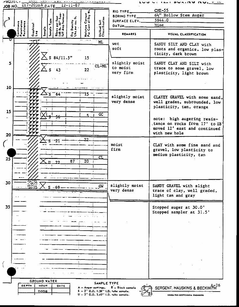
L \ J \ t r v a r A - l I ) \ r { r f l \ f ( \ l \ r . e ^ e
ir' I ,,,a;:i
c
3 o: o
O J
aaEo
ag
agEoiifliii : ! | ; i
_ =: t: o( r ca ?: :: Uo a= o ,
Co
o o
a ' :€ r
= J3 U
p16 lypE CME-55B6RING TypE 6k" Hol low Scem Augers u R F A c E e l e v . 5 9 4 4 . 0DATUu )line
RE|rARXS Yrsu^L cLAsstFtC ttOx
5
10
15
20
(
30
35
I'C E
\ s o f tI\
SAI{DY SILT AND CLAY wirhroots and organics, low plastlcicy, dark browr
TX'At
84 /11 .5 " 15
CL-ML43 22
sl ighcly moiscto moisiverv firm
SAI{DY CLAY A}ID SILT wichtrace to sone gravel, lowplast ic i . ty, l ighr brown
sllghcly moistvery dense
CLAYEf, GR.tt/EL with sooewell gradeo, subrounded,plasci.city, tag, orange
sandlow
note: high augering resis-: tance on rocks froq 17t co I8uoved 12' east and continuedwith new. hole
=%= moistfirn
CLAY wlrh soue fine sand andgravel, low plast ic i ty couediuo plascici ty, can'.//,:
t .///., , . n . l Z 87 i 20 i
% I
I
t
S -69- -- ; - -.- --GI{ - sl ighcly moi.stvery dense
SAI'IDY GMVEL wich slighctrace of c lay, wel l graded,light tan and gray
Stopped auger atStopped sampler
30.0 'a t 31 .5 '
G R O U N D W A T E R
o E P T H I H O U F I O A T ESAMPLE TYPE
A - Aogrr cct tangr. 8 ' - Elocl :onp|rS - 2" O.D. 1.38" l .D. rubc ronelr .U - 3" O.O. 2.a2" l .D. tubi rooolc.
- ' - A=26r[$*]r SEHGENT. HAUSKINS A BECKWIIH
- l H l -
tV 'Bl t m**f tca.-EsG
i r R O J t L r . - = , . .
,Orng. I: i-20:.:eOAfE_
o E P T H I H O U R O A I ES^TPLE TYPE
A - Augrr Gutti.gr. I - Slocl rooolcS - 2" O.D. lJg" l.D. tobo rompb.U - 3" O.D. 2-a2" l.O. tobc ronclc.
\ v \ J v a r t - l & \ r , ( . t f l \ , t N V o ! - ' . ,
L-?7I SERGENT. HAUSKINS & BECKWTTH
i,,r € r
3 :3t ! a
: c .c a aJ A C
c9
33 o. c
O J
ac€c
aA
aeEo
- i !3s E
ii;i 3€i : !
s
: iC -a a
o a- . .L 4
O J
- ;! r: a( r ca :i :
: ui :=o .
Ca= :
c o
a :3 r
? Jf ( J
R I G T Y P EB O R I N G T Y P E -SURFACE ELEV.DATUM
RElrARXS vrsuAL cL SS|FtCATtON
:-:--
:- : .; l i
I , t il l lt l t i l l l
OT DRILLED
i It i , ! i
I II
( '
(
I
F! l
II
i t ,
-l i
r l
G R O U N O W A T E R
coaaEcGcoltc€{ cKeG
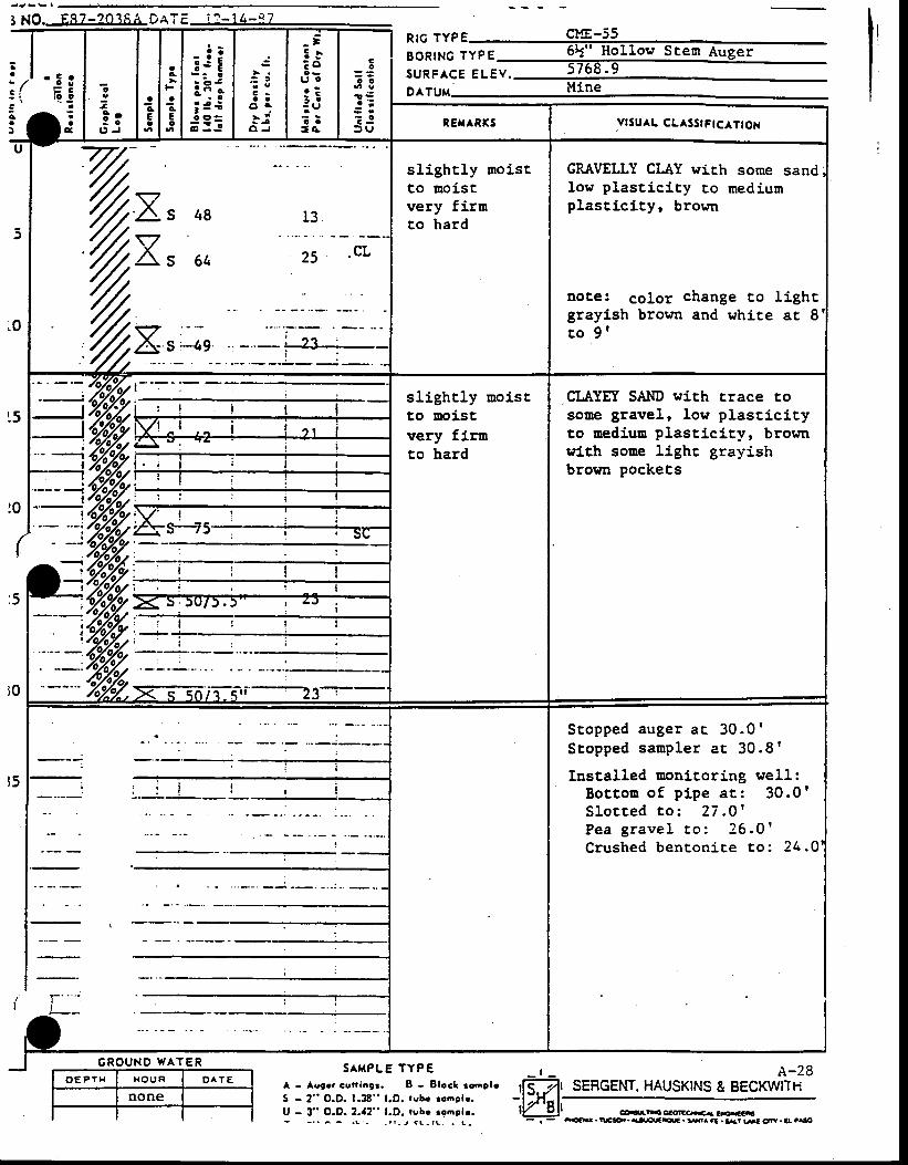
I NO.--E8-Z=203,54DA T E i ? - 1 4 - - c 7
i r ' 'EEl i: : l c o I . e
\ \ - IC ' I J
i- j l;;aAEc
ac
aAEo
EJE:i;i f €; : =
.i
: t
C ra a
o a; i
O J
_ ]: iE ou oa :i a: ei := G
Co
o c
a :
? l= ( J
p16 1yp6 Cl9-55
BoRtNc lypE 6L" Hol low Stesr Augsr
S U R F A C E E L E V . 5 7 6 8 . 9
ortuu Mine
REfTARXS YISU^L CLASSIFICATIOX
U
)
0
5
5
I
r3fr?
. t q . v !
, L J -
sl ight ly uroiscto moistvery firnto hard
GRAVELLY CLAY wich some sandlow plastici.ty ro mediumplast ic icy, brown
note: color change to l ightgraylsh brorm and whire at 8t o 9 t
- -' , %%y i--:-slighcly moistto oolstvery firuco hard
CLAYEtr SAI{D with Erace tosooe gravel, Iow plasticityto mediuu plasticity, brownrith sooe light grayishbroqm pockecs
t / -: l
vt ^a .-.-l ) l{ J e . i a
I
i . i l i I! l I
II
)aJ
\ !t- i
4 SC
ffiT_--..t{-
I
I
!
II
Stopped auger ac . 30 .0 'S topped sampler ac 30 .8 '
Installed monicoring well:Bo t tou o f p ipe ac : 30 .0 fS l o r r e d r o : 2 7 . O 'P e a g r a v e l t o : 2 6 . 0 'Crushed benton ice to : 24 .O
AI{P TYPG R O U N O W A T E R
!0
|0
r5
A - Aoger cuningi . I - Elcc l ronpleS - 2" O.D. 1.38" l.O. rubc rcosh.U - 3" O.D. 2.a2" l.D. tubc rooelr.- - r r ^ ^ . L _ _ r r , J < L - r L . . _ ! -
A-28SEFGENT. HAUSKINS & EECKWITIit,w),
- . - m. wggo.. {rtffts|* . 5^ .t . EAr lst cfr . e! ,.lo
! P R O . r s ' - r - - - n l L : 1 , ' : . :'JO8 NJ. E87-203E4 DATE
o E P Y H I x o u n I o e t eSAMPLE TYPE :
Lg ( i o r r e5T Ec& . lHG No . p -a r
A-29SEFGENT, HAUSKINS & BECKWITH
(' I ,i, l =ajjjl;;
a
A
Eo
ac
aAE0
- : !t€ Eii',; 4 ii3=
C -a a
o e
- 4O J
- ;5 .: ou t co Z: ::(,o a
T C
cc
o o
1 3a ' :
5 r
: J> U
RIG TYPEEORING TYPES U R F A C E E L E V . ,D^TUM
REHARKS Yrsu^L cLASS!FtCA?tOx
r lF
Fl l- : r
F
IIlI
r ! l' -'--
G R O U N O W A T E R
A - Aogre cuftangr. 8 - Elcal :6nelr : l<-.}tS - 2" O.D. 1.38" l .D. rubg.ronolr. ; l : f i^| .U - 3 " O . O . ? - 1 2 " l . O - r u b c r o a o l c - l V O l l
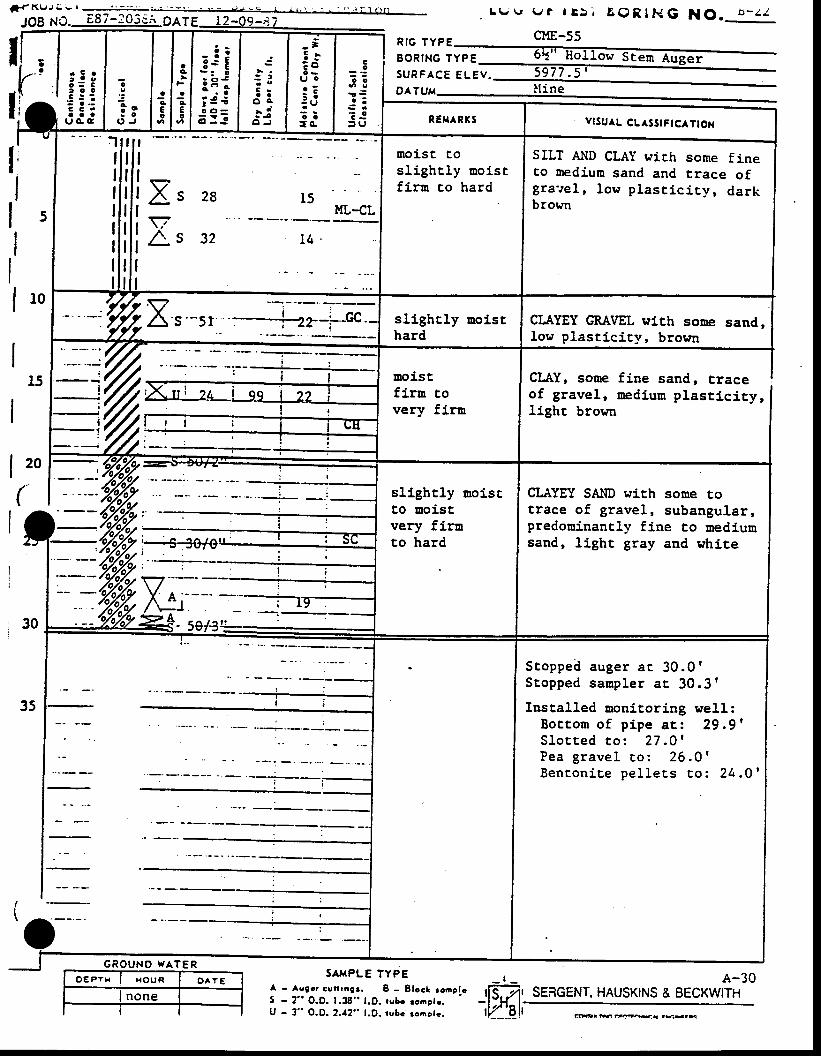
: 5 t, a o. : : :C C 'c a a
U C E
Rlc rYPE cME_55
E O R I N G T Y P E
. L e t e t l t > ; E O R I H G N O . b - z l
SURFACE CUEV.
CLAY, sooe fine sand, craceof gravel, uedium plast ic i . ty,light brown
20
(
i i
SATPLE TYPE A-30SENGENT, HAUSKINS & BECKWITH
aa
aaEo
_! i3s E
:i;i 3 €i : !
C ra a
o a- da i
O J
_ t: l; ou o
o - -: :: ( ,t ::o .
co
o o
a :€ r
T J: U vlSuaL cLASStFtcATtOx
l q
ML-CL
moisc t,osl ighcly moistf i rn co hard
SILT AIID CLAY crich some fineto mediun sand and trace ofg ra i re l , low p las t i c i t y , darkbrown
i i r,..'s'-sr ', --i-z2.j--Gc' sllghcly troisthard
CLAYEY GRAVEL nirh sone sand,low plast ic i ty, brown
%moiscfiru tovery firu
slighcly aolsrto aoistvery firuto hard
CLAYEY SAIID with sone cotrace of gravel, subangular,predonj.nantly fine to uedLumsand, llght gray and whi.re
Stoppe i l auger a r 30 .OlStopped sanp ler a r 30 .3 f
Inscalled monitoring well:Boc tom o f p ipe a t : 29 .9 'S l o t t e d t o : 2 7 . 0 'Pea grave l co : 26 .O 'Benton iLe pe l le ts to : 24 .0 '
G R O U N O W A T E R
A - Aogcr cufrrng3. B --8tocl ,o-pl. , fFb,5 - 2" O.O. 1.38" l .D. rubr rcostr. : l l ){^|U - 3" O.O. 2.!2" l .D. rubc :oaotc. lY_6ll GrE@ry{ a* - rG
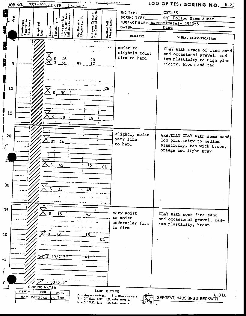
. loa No. F87-i03i OT TEST BORING NO. B -23-t Q G
XJA- - -rj8-* -
R I G T Y P E
EORING TYPESURFACE ELEV.D A T
SA^{PLE TYPE
o{E-55co
o o
j €a ' :
: o
> 9
l5ItJtoIIIttIIi tol
tr I
s; 33
sERcENr. HAUSKTNS r ,..**fiit to
r C r
3: gt 3 c. : : - 'C C 'o a a
U G C
aa
JcCo
- : it s E- : o
i i ;; r iO O -
o- I !
: t
C sa a
o c- i
O J
_ =: .E o
U Or ?i a: U; :ro . YlsuAL CLasslFtcATtOx
VAs. 16X U JO. .
molst tosl ighrly moisrf irn to hard
CLAT wich trace of fine sandand occasional gravelr f l€d_iuur plast ic i ty co high plas_cicic)r , brown and E.an
slighrly moisrvery firrnto hard
CRAVELLY CLAY wirh sonelow plastlcity co mediumplast ic icyr tan with brown,orange and light gray
very noistco moistmoderat ley f i rnto firur
CI"AY wich some fine sandand occasional gravel, med-iun p las t i c i t y , b rorm
S cern
q q n / < < r l- . J v t J . J
| - A.ugrr cuniogr. 8 - gtoct ronplc ,[T?fs - 2" o.D. 1.38" l .D. tsbo ronote. - t -Lr t .
u - 3 " o .o .2 . r 2 ' , j . o . r vbc roao r r . i l , / ' 8h
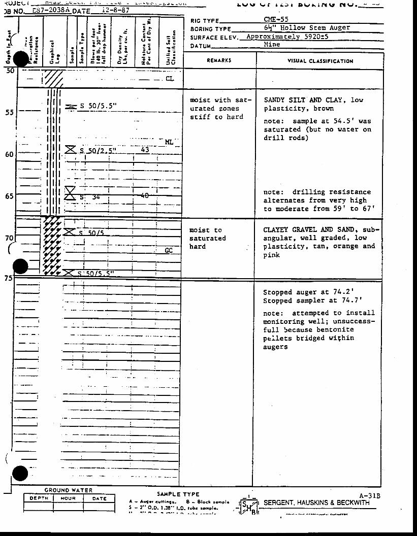
a4
aAEo
- i it€ E:ii; 3 ii : !
: t
C -a t
o ca i
O J
_ =5 .: o
l | €a - -: :: vi ::o .
Co
o o
a ' ;
t J3 s vrsu L cL sstFtcATtox
!
I CL
50 /5 .5 "
- ' - - M L "
X. sLsolz-s:: ' :-lJ:-_
-' : i ! i ! a
noist wich sac-urated zonesst i f f to hard
SAI{DY SILT AI'ID CLAY, lowplast ic icY, brown
note : sanp le aE 54.5 ' wassacurated (but no water ondri l l rods)
not,e: dri l l ing resistancealternates froo very highto moderate frou 59' co 67 |
%moist tosaturatedhard
CI.AYEIY GRA\IEL Al{D SAI{D ' sub-angular, well graded, lowplasti.city, tan' orange andpink
Stopped auger ac 74 .21Stopped saup ler a t 74 .71
note: at tenpted to instal luonitori.ng well; unsuccess-full because bentoni.tepel.lecs bridged wiqhinaugers
L \ r \ , \ , / f r . A r t D v A l n l \ r N \ l o - - J
p16 lypg cuE-55BoRtNG TvpE 5k" Hol low Steu AugersURFASE e lev . Approx ina te ly 5920t5911gM ltine
' : r
G R O U N O W A T E R
O E P T H X O U R O ^ T ESAI{PLE TYPE
A - Aggor cun iogr . I - S loc l roap lcS - 2 " O.D. t .38" l .O. tubc :onp le .i l a . . A r ^ . , , ! - - _ _ - t -
A-3 IBSERGENT. HAUSKINS & BECKWITFi
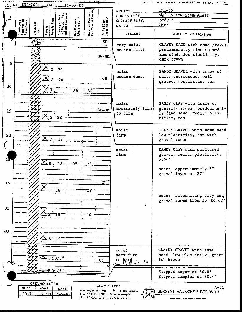
a f f \ v , - Y I +
JoB NO. E8; -20 : i$ - : . DATE t2_n5_87, . - - r > y 4 . . \ \ t r r t V o
i
I :5 tt c o
: : :C C 'o a a
U G gI€
3 o: c
| , J
acEo
aa
acEo
- i !t s E
i i ii 3€;:t
| - ;
,i | :i;l | :jr - i I i :
o J | : c
co
o q
a Sa :
E J3 U
Rtc rYPE cME_55
EoRrNG l vp g
SURFACE ELEV.orruM
REl|^RXS vrsuAL CL^SStFtc T|OX
zFF very moistmediun st i f f
CLAYEY Stu\D wich some gravelpredorninancly fine to med-iun sand, lo r l p lasc ic i ty ,dark brown
5
l0
t5
20
(
I
3C
35
40
%X' 30%,Xu 24 cs
- .V Y',- .- --uu-jr-.'---
noistmediun dense
SAIIDY GRAVEL with crace ofs i l t , subroundec i , we l lgraded, nonplast ic, tan
moistuoderately firnco firn
SA,NDY CL{I with trace ofgravel ly zones, predominant-ly f i.ne sand, medium plas-t ic i t ]" Ean
\ noist
\t"'
CLAYEY GRAVEL with some sandlow plascicicy, tan withgravel zones
moistfiru
SANDY CIIY wicb scatteredgravel, neci ium plast! .c i ty,brown
note: approximately 5"gravel la1'er ac 27'
noce: alcernat lng clay anci.gravel zones frorn 33' Eo 421
CLAYET GRAI'EL wich somesand, 1or " ' p ias t i c icy r g !€€o-ish brown
moisEver;- f irnt o h a r d - A -
* H t Q J o ' ' o '
\S c o p p e d a u g e r a c 5 0 . 0 'S topped s : rmp ler ac 50 .4 '
G R O U N D W A T E RSA^{PLE TYPE
A - Augrr curt ingr. I - Bloc! ronplqS - 2" O.D. 1.38" t.D. rvbc ronolo.U - 3" O.O. 2.12" l .D. robj roaote.
SERGENT. HAUSKINS & BECKWI]H
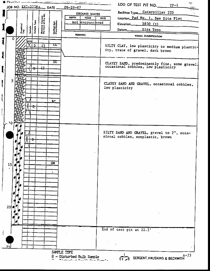
I Pi \vJ:L I
JO8 NO. FF7-? t i 8A OO*
GROUND WATER
tOG OF TE5T PII NO. TP. I
Elevario
Backhoe Tyot CaterPillar 235 :-
16g61;6n Pad No. l , See Site planoE?n{ HOUR OAIE
not encounE red
SILTY SAI'ID AI.IDsional cobbles,
GRA\IEL, gravel to 2'f , occa-nonplast ic, brown
l !'|,
SNMPI.E I.:IPED - Dish:rbed BuIk Sar.ole- n t - ! . _ L - J ^ _ _ t t B _ _ F _ _ .
SILTY CLAY, 1ow plast ic icy co medium plasr iciEy, t race of gravel, dark brown
CLAYEY SAllD, predonipantly fine, some graveloccaslonal cobbresr low plast ic icy
CLAYEY SAIID A]ID GMVEL, occasional cobbles,low plascici ty
End o f r es r p i r ac 22 .3 '
I e-3:G2, SERGENT. HAUSKTNS & EECKWITH
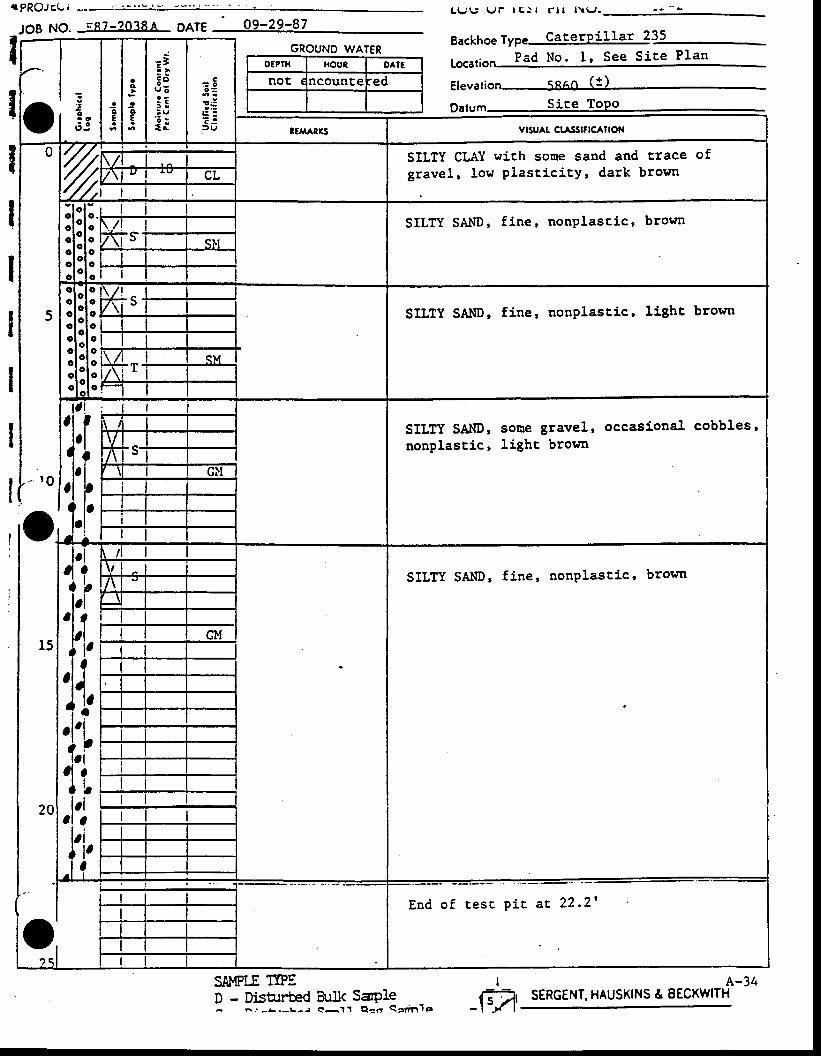
r PROJEL I
Backhoe Type CaterPillar 235 -
Lo..rion
Elevat ion Snen (!)
DatumIIIIIII
SILTY SAl.lD, fine, nonplascic, brown
SILTY SAI{D, sone gravel'nonplasti.c, light brown
If-r
-1'A
occasional cobbles'
SA},IPLE TIPED - DisUrrH Btrlk
A-34SERGENT. HAUSKINS & EECKWITHSaple
Elaa Sann'le
L U g V r l c l l r l r l \ \ J .
O€PIH HOUT DAIE
noE ncounEe ed
oi s'l:SILTY CL,{Y wich sone sand and trace ofgravel, low plascicicY, dark brosn
SILTY SA.tlD, fi.ne, nonplastic, brownoooo
SILTY SAI{D, fine, nonplasti'c, light brown
It?qi .
E n d o f t e s t p i t a r 2 2 - 2 '

O€PTH HOUT o^lg
n . l r Lcounte ed
f | 1 \ r r J i - e | - -
JOB NO. EE7-2038A 9ATE 09-24-87
SAMPI.E TI"E
LOG OF TEST ?IT NO.
Eackhoe fype Caterpll lar 235
1o."1;on Pad No. 1, See Sire p lanGROUNO WATER
Elevatio
! - Pi"ur"bed tulk Sapleq _ h s - L . - L ^ , < r _ t i h _ _ a - _
SILTY SAIID AND GRAVEL, gravel !o l,', occa-si.onal cobbles, nonplastic, brown
SILTY SAIID ANDplast ic, broun
GRAIfEL, some cobbles, non-
A-35SERGENT, HAUSKINS & EECKWITH
Site Topo
YtSUAt Ctast;tcAtroN
CLAYEY SILT wich sone sand and crace ofgravel. low plast ic i tv. dark brown
SAI{DY CIAY, uediuu plastj.cir}, Iighc brown
SILTI SAIID AIID GRAI|EI", gravel ro 3',r occs-sional cobbles, .nonplastic, browr
End o f tes t p i t ac 24 '
I
- \s -Ar
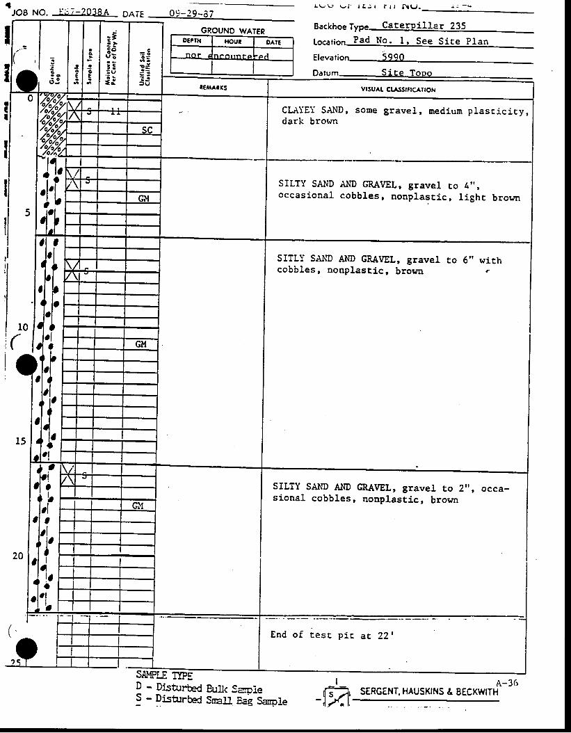
GROUNOWATER
L \ - ' L , U f l t r j l f r t N \ J .
SITLY SA\!D Al[D GRA\IEL, gravelcobbles, nonplascic, brown
Backhoe fype CaterPillar 235
to."tion
Elevat ion 5Qa0
Dalum
Iia
I
to 6" withe
l0
(
SILTY SAND ANDsional cobbles,
CRAVEL, gravel to 2", occa-nonplastic, brocln
(
')
SAMPLE TIPEI-FaD - DisturH Bull< Sale
! - Dlsb:rbed Srnat'r eai Sanofe
A-3(rSERGENT. HAUSKINS & EECXWITH
o€Prx HOUI OAIE
n . | t n a n t t n l ' a ' e A
CLAIEY SAI{D, some gravel, medium plascicicy,dark brown
SILTY SAND AllD GRAVEL, gravel co 4',,occasional cobbles, nonplast ic, l ighc broun
End o f tesc p i r a t 22 t
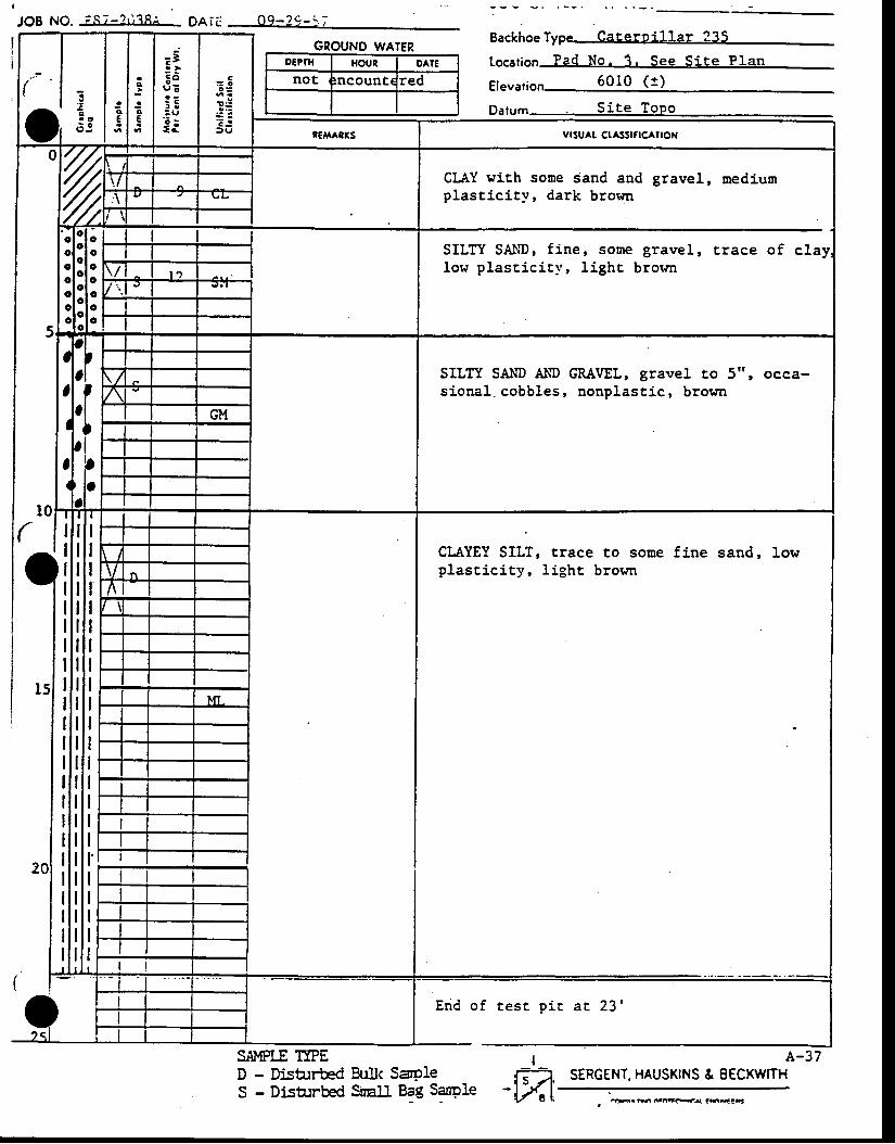
JOg NO. ;S7 -? r "?8^ l DA IC Oq-2q - : ;: - - -
Backhoe Type Cateroillar 235
Lo."tion
Elevati 6010 (1 )
Datum Si te Topo
WATEROEPIH HOUR OATE
not Incount( red'.1 :, 1; vrsu^t cl^ssrfrcAltoN
CIAY wi.th some sand and gravel, mediumplast ic i ty, dark brown
SILTY SAltD, fine, some gravel, trace of claylow plascici ty, l j .ght brown
SILTY SAIID Al{D CRAVEL, gravel to 5", occa-sional. cobbles, nonplast ic, brorrn
CLAYEY SILT, traceplast ic i ty, l ight
to sotre f i.ne sand,brown
Erid of test pic at 23'
SA},IPIJ Tl"ED - DisUrrH Bulk SryleS - DisUrrbed Sralt Bag Sarole
A-37STRGENT. HAUSKINS & BECKWITH
I-ffi:rGrr6@G6{ CS{EG
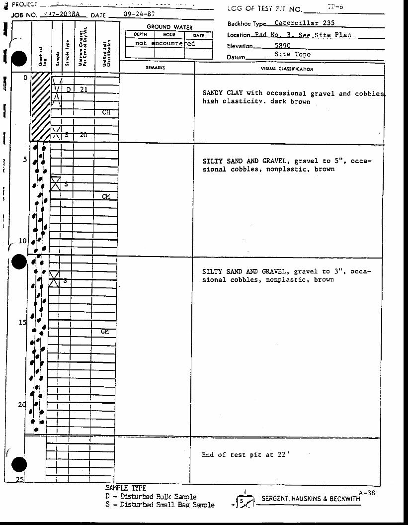
OEPIH HOUI DATE
noc lCOUnCe ed
.l
{
IIlII
I
rx l rJ c ' - I
JO8 NO.rcc oF TEsi PtT NO. : t -o
Beckhoe ttp"
Locafion
El"r"tio.r . r r r r ra S i te Topo
09-24-8;
GROUNO WATER
SILTY SAI{D ANDsional cobbles,
GRAVEL, gravel to 5", occa-nonplastic, brown
SILTY SAI{D A]{Dsional cobbles,
GRA\aEL, gravel to 3", occa-nonplast ic, brown
,'fI
?II
bI
ir
End o f ces t p i t a t 221
SAMPLE TPED - Disb:rH Sull( S41eS - Disturbed SreIL Bae SanDle
A-38SERGENT. HAUSKINS & EECKWITH
I-m,
= 5o :
: :'a:f r,,
SAI'IDY CLAY wich occasional gravel and cobblehieh plasEici tv. dark brown
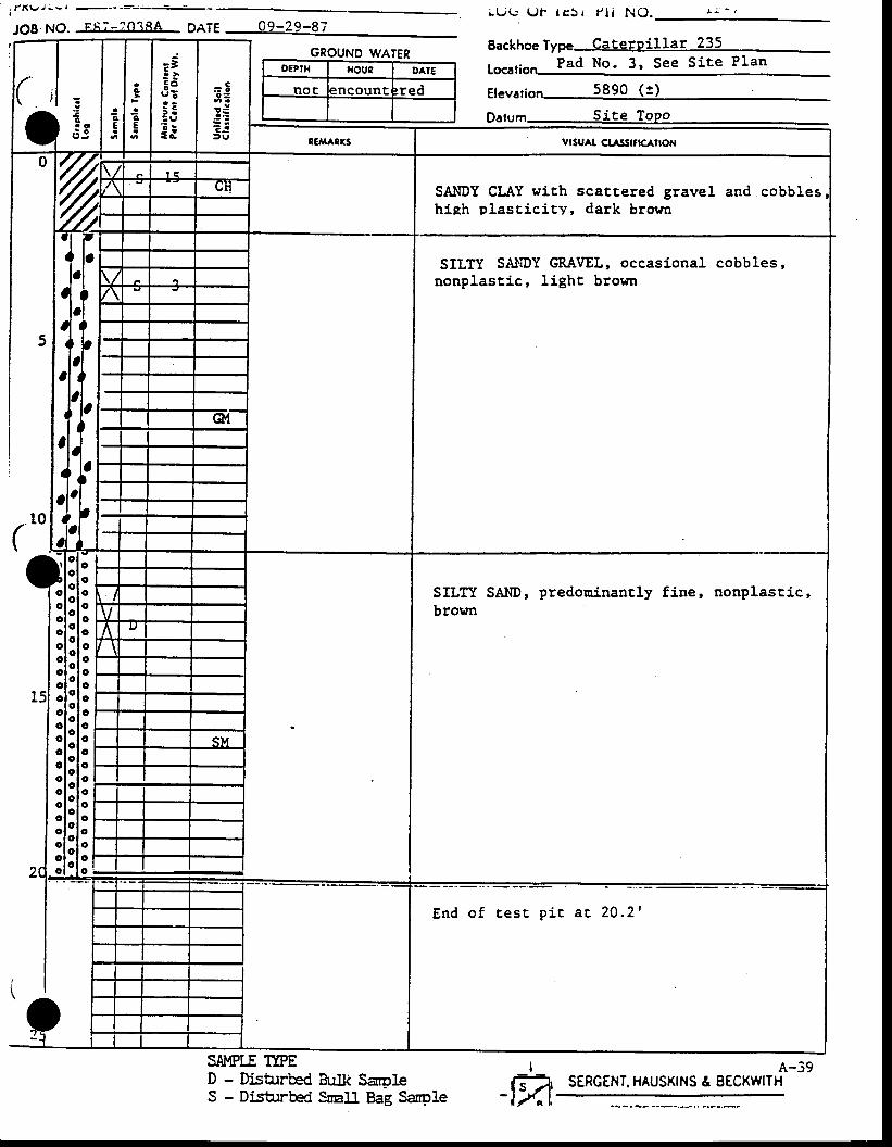
! f X L / J l - l - - ' - : r : - -
JOB NO. FA;-?niRA OATE 09-29-87L U G ( J I I E 5 i P I ' N O .
Backhoefype Cateroillar 235Pad No. 3 , See S i te P Ian
g1",r"1;6,., 5890 (t)
p61urn Site ToPo
SILTY SA}IDYnonplast ic,
GRAVEL, occasional cobbles,light brown
GROUND WATERO€PIH f{out OAIE
noE 3ncount red
vrsu^t ctastrK^troN
SAIIDY CLAY with scattered gravel and.cobbleshieh plast ic i ty, dark brown
SILTY SAND, predouinantly fine, nonplast,ic,brown
End o f Ees t p ic a t 20 .21
SAMPIJ Tt"ED - Disturbed tsulli SanpleS - Distrrbed SnalL Bag Sanp1e
A-39SERGENT. HAUSKINS & EECKIYITH
I-ffi:,
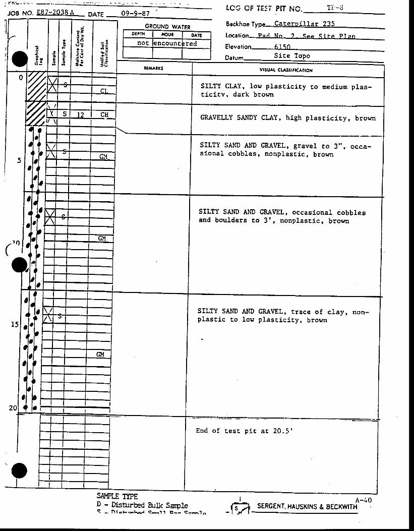
JOB No. E87-2038A pals
GROUNO WATER
SAI,{PLE TPED - Disarrbed BuIk SaroleS - l . \ i< { . r rh6 / eq l1 E l - ' - ( : * ]o
tCG OF TESI PIT NO. r l - o
Eackhoe fype Caceroillar 235
Lo..tion
Elevat ion 6l 5OSice Topo
I
-1"4'A-40
SERGENT, HAUSKTNS & EECKWITH
DEPTH fiout OAIE
noc 3ncount red
SILTY CLAY, low plasticicy ro medium plas-t ic i tY. dark brown
GRAVELLY SAI{DY CLAY, high plasciciry, brown
SILTY SAIID AND GRAVEL, gravel co 3,', occa-sional cobbles, nonplast ic, brown
SILTY SAI{D A}lD GRAVEL, occasional cobblesand boulders to 3r, nonplast ic, brown
SILTY SAI{D AIVD GMtfEL, rrace of clayr Don-plast ic to low plast ic i ty, brown
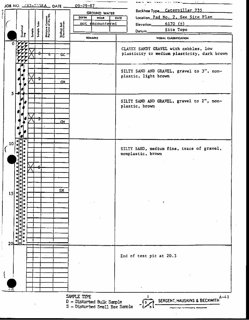
GROUND WATERDEPIH HC'UT OATE
not t lcounte :ed
JOB NO. ; :A?_?.^, iRA oare 0g_29_97
SAI,IPLE TTPED - DisArrbedS - Disturbed
SILTY SAI{D, mediuu fine,nonplastic, brown
Eackhoe Type Cateroillar 235
tocarion Pad No. 2. See Site Plan
ElevarioSite Topo
trace of gravel,
IBr: lk Sa.oie f f i ,SrnaIl gal Sarole
-L,/al'
A-4 ISERGENT. HAUSKINS & BECKWITH
vlsu^t ct^Ssrflc^rtot{
CLAYEY SANDY GRAVEL wi.ch cobbles, Iowplast ic i t .v to nedium plast ic i ty, dark bropn
SILTY SAND AND GMVEL,plasr ic, l ight brown
SILTY SAND AIID GRA\IEL,plast ic, brown
gravel to 2", non-
E n d o f t e s t p i c a t 2 0 . 3
* .v<4du ' * *3G
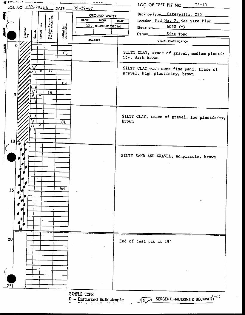
IOG OF TE5T PIT NO.JOB NO. ,E87-203SA na16
GROUND WATER Backhoe Type Cateroillar 235
!lr lil
SILTY CLAY, r tace of gravel, nedium plasr i :_ity, dark brown
SILTY CLAY wich some fine sand, trace ofgravel, high plast ic ir j , brorrr
SILTY CLAY, trace of gravel, low plasrlci.t3,brown
SILTY SAr\D AllD GM\|EL, nonplastic, brown
OIPTX HOUN DAIE
noc encount rred
SIMPLE T1PED - DisturH B:lk SaoleF
I
-1"4 SERGENT. HAUSKINS & EECK\{ITfi-i:
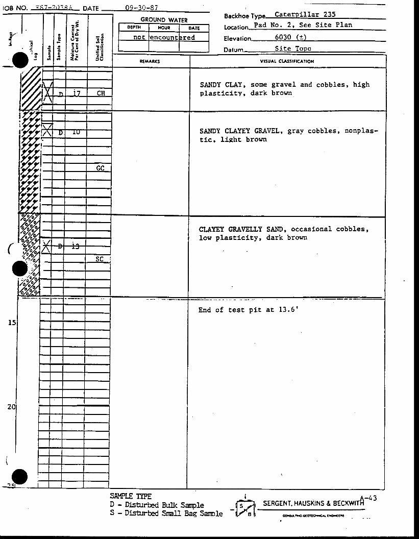
v'Ia
_o
tgg NO. ;s7_?i ' t i i i Oafe 09_30_97
GROUNO WATERO€PTH rKtut OATE
noc encount :red
Backhoe Type CacerPillar 235
1o."1;o,., Pad No. 2, See Site Plan
E1.r"116n 6030 (t)
Datum Site ToPo, o
o
12
SAMPLE IIPED - Disturbed BuIk SaoleS - DisArrbed SnaMag Sarole
I-m
vrsu^t ctastftc^noN
SAl.lDY CLAY, sotre gravel and cobbles, highplast ic icy' dark broun
SAIIDY CLAYEY GRAVEL' gray cobbles, nonplas-tic, lisht browa
CI,AYEY GTAI/EI.LYlow plasticity,
SAI{D, occasi.onal cobbles,dark brown
End o f tes t p i t a t 13 .6 '
!r sERGENT. HAUSKINS & EECXWIA-43
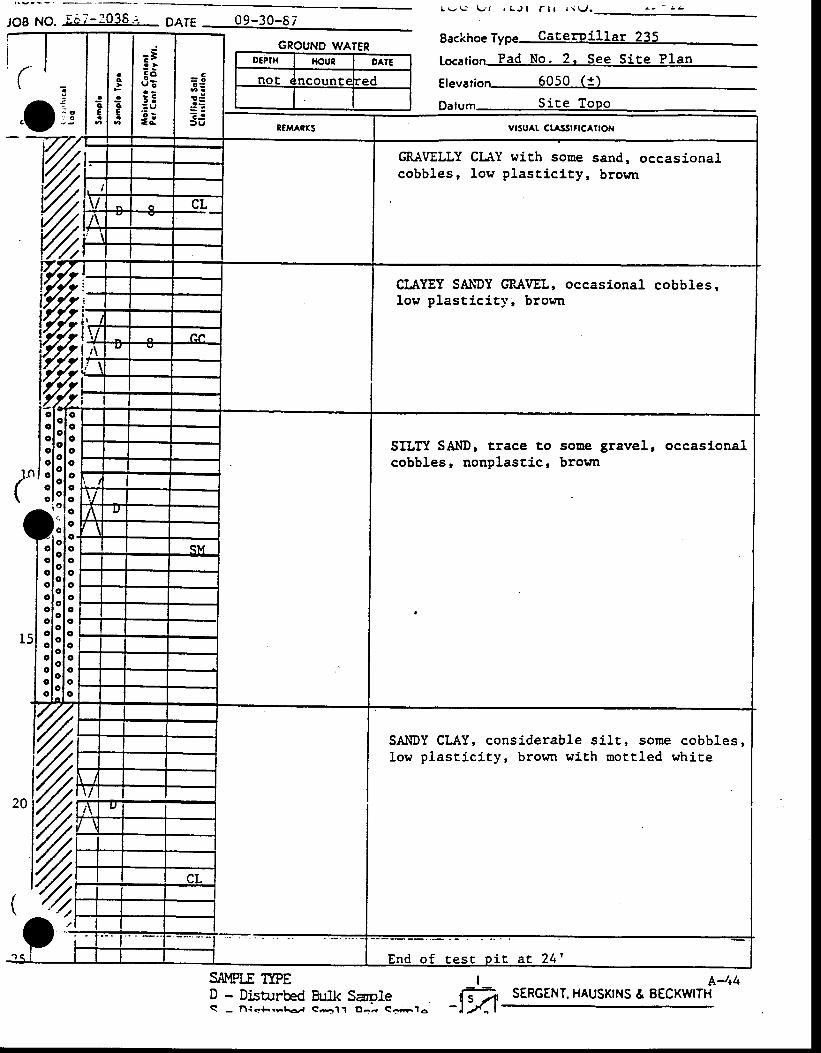
JOB NO. Ec7-3036.; DA1E
GROUND WATERO€PIX r|out OAIE
noE ncount€ :ed
t v ! - l - , t r C J l l - l t l \ \ r f .
Eackhoe Type CaterPillar 235
1s661;en Pad No. 2. See Site Plan
g1Ey31;en 6050 ( i )
pulr' '. ' Site Topo- . :- I : t'v"-
SILTI SAIID, Erace tocobbles, aonplast j .c,
sone gravel, occasionalbrown
%SIMPLE TTPED - Disbrrbed BuIk SaoleQ - l. l iaJ-rrr€J eEl1 O-- So;f o
SAI{DY CLAY, considerable siLt , some cobbles,low plast ic i ty, brown with nott led white
A-t+4SERGENT. HAUSKINS & EECKWITH
I-m,
GRAVELLY CLAY wich sonecobbles, low plast i .c i . ty,
CIAYEY SAIIDY GP"AVEL, occasional cobbles,low plast ic i t .v, brosn
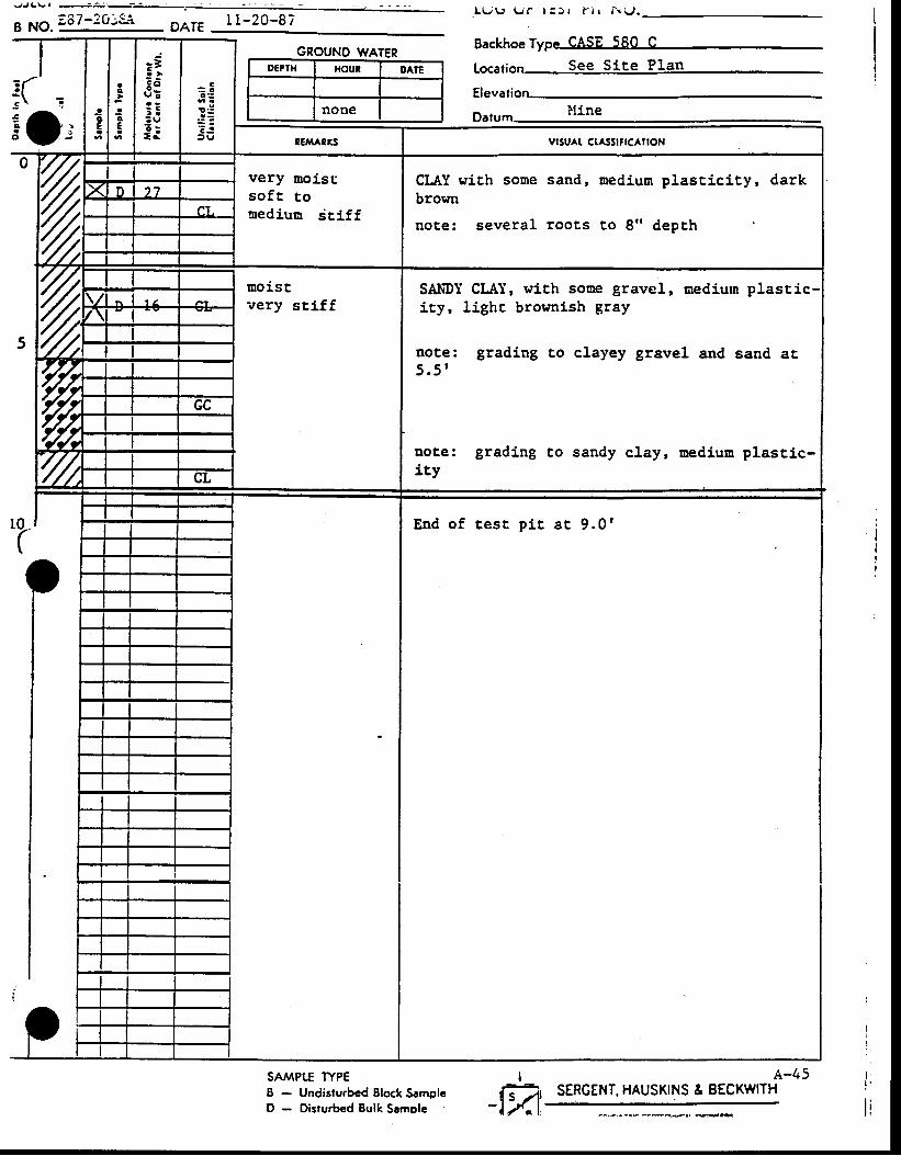
! . rJL\.1 ---
I NO.;87-20:Si DAT€ I 1 -20-87
GROUND WATERD€PTH HOUN DAlE
none
SA/vlPt^E WPEB - Undisturbcd Elock SamplcD - Disturbed Bulk Sarnple
L L / \ , U | - t ! , ) | f l r N v l .
Backhoe Type CASE 580 C
16661;e6 See Site Plan
Elevati: ( zso, l f i n a
Datum "-"-
t e s t p i t a t 9 . 0 r
A-45SERGEI{T. HAUSKINS & EECKWITH
Imt
vrsu^t ct^ssrflc^noN
very moistso f t tonediun sriff
CLAY rdth some sand, nedium plascicity, darkbrosn
uote: several roots to 8" depth
moistvery sri.ff
SNDY CLAI, wi.th sone gravel, nedium plasticity, lighc brownish gray
note: grading to clayey gravel and sand at,5.5 '
Dote: grading Co sandy clay, uedium plastlc-ity
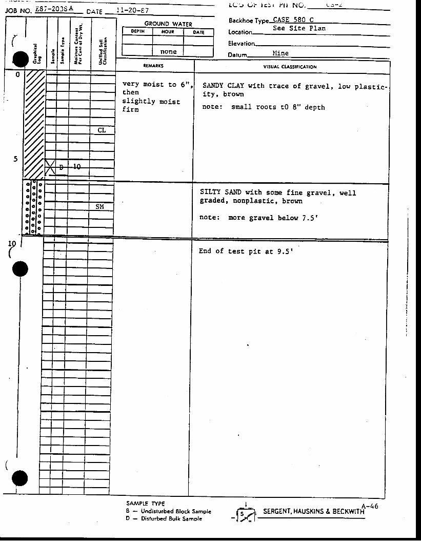
JOB NO. ;8;-20354 crie l t -20-t7 L U ' J ( . l l l i S r f l l N O . L ) - a -
Eackhoe Type CASE 580 CSee Slte Plan
GROUND WATERO€PTH fioun OAIE
none
SAAAPE TYPE8 - Undisturbcd Block SamplcD - Disturbed Eulk Samole
Elevation
End of test p i r ar 9 .5r
SERGENT. HAUSKINS & EECKWIT#-46I-FA
l:, It
7%
very noi.st to 6"thensl ighr ly noisrf irrn
SAIIDY CLAY with r,race of gravel, low plasric-i ty, brown
note: snal l rooEs t0 8" depth
SILTY SAI.ID with sone fi.ne gravel, wellgraded, nonplastlc, browa
note: Eore gravel below 7.5'
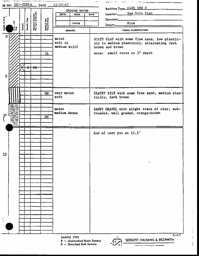
l . o1 : O
.(s3
! l
)8 NO. E87-2038A DATE r i -20-5 7
GNOUNO WATERO€PIH '{OUR OATE
none
SAAAPTE WP€B - Undisturbed Elock SamplcD - Disturbcd Eulk SamPle'
Backhoe Type CASE 580 C
tocati See S i te P lan
Hine
I-ffi:^
SILTY CLAY with sone fine sand, low plastic-i ty co medium plast ic i ty, al ternat ing darkbrown and brown
note: srual l roots co 3" depch
uoiscsof t touediuu stiff
CLAYET SILT wich.soue fine sand' mediuu ptl.cityr dark brown
very uoistsoft
SAI'IDY CRA\IEL lrith slight trace of clay, sub-rounded, well graded' orange-brown
uol.sguedluu dense
E n d o f t e s t p i t a t 1 1 . 5 r
SERGENT. HAUSKINS & EECKWITH
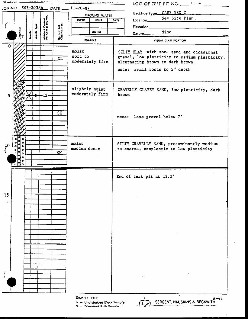
JoB No. iE7-20384 DaTE
GROUNO WATERO€PTH XOUT OAIE
none
SAAAPTE WPEB - Undisturbcd Elock Samplen - h : . . . . ,L -J o , . l t , < 'a^ f -
TOG OF TE5T PIT NC.
Backhoe Type cAsE 580 Cc a a $ i g s P I a n
Locaf ion ---
.:ao. o6J
SILIT GRAVELLY S&\D,to coarse, nonplast ic
pre<iominantly mediuuto low plast ic j . ty
End o f tes t p i t aE 12 .31
I
-1"1'A-/r8
SERGENT. HAUSKINS & BECKWITH
moistso f t tomoderately firm
SILIY CLAY with sone sand and occasionalgravel, 1or, ' p last ic i tv to mediurn plast ic iry,alternacing brown to dark brown.
note: snal l . rooc,s t ,o 5" depch
GRAVELLY CLITYEY SAI{D, lowbrowu
p lasc ic i ty , dark
note: less gravel below 7'
slightly moisrmoderately firn
uoistmediun dense
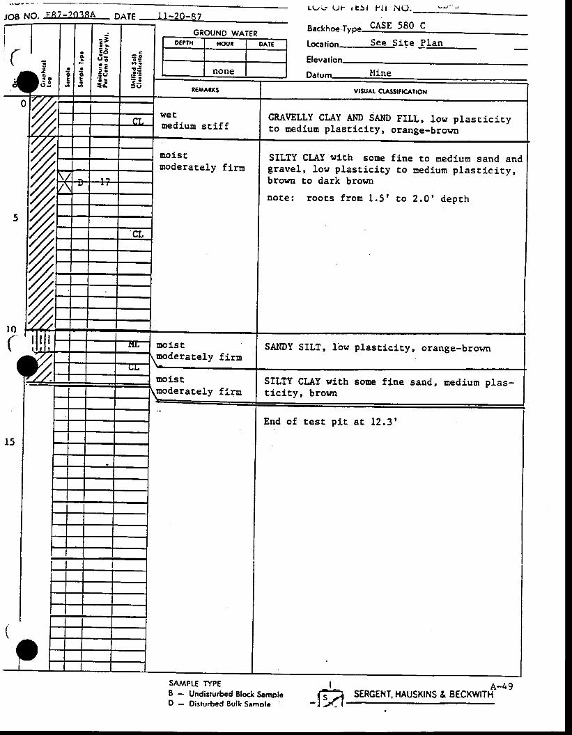
JOB NO. FR7-?O?8A DaTEL 9 v . U t _ r E 5 t P l l N U . v ! - - J
GROUND WATER Eackhoe Type CASE 580 C
r0(
r5
O€PTH HOUi I OAIE
none
SAAAPIf TYPEI - Undisturbcd Block SamplcD - Oisturbed Bulk Samolc
1o."11on See Site Jlan
Elev
SAIIDY SILT, 1bw plasticity, orange-browr
End o f tes t p i t a t 12 .3r
I
-ffi SERGENT. HAUSKINS & EECKWIT'f-4,
hreturediun sriff
GRAVELLY CLAY Al.lD SAIID FILL, low plasricicyto aedium plasticity, orange-brown
,%
aoistuoderat,ely flrn
SILTY CLAY wlth somegravel, low plasticicybrorn co dark brorlrr
note: roocs f rou 1.5 '
fine to nedium sand andto eed ium p lasc ic i ty ,
t o 2 . 0 ' d e p t h
uoistmoderaLely fi.rn
moderarel,y firaSILTY CLAY wlth soae flne sand, medium plas-tlci.ty, brown
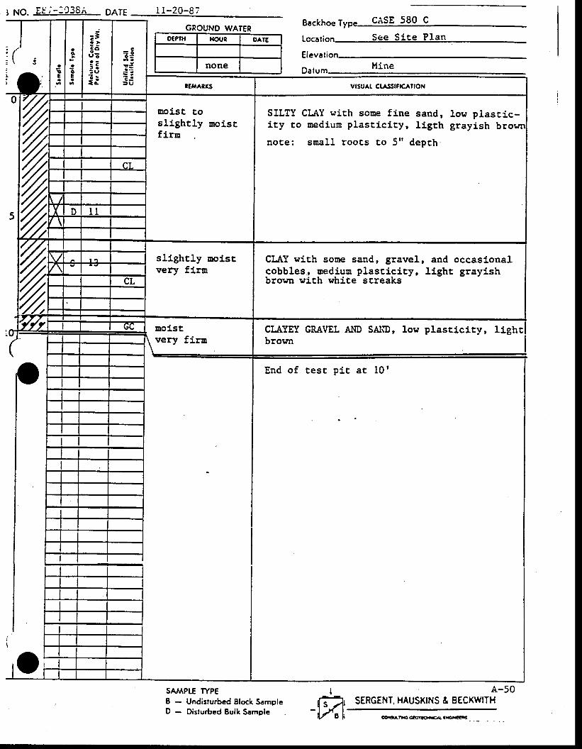
I NO. E! i -1C36; palg i l -20-87
GROUNO WATERO€PIH I{C'UR OATE
none
SA'IPTE WPE8 - Undisrurbed Elock SamplcD - Disturbed Bulk Semple
Eackhoe T cAsE 580 c
1ss61ie6 See Si te Plan
Elevati
Da
End of test pi t at 10 |
A-50SERGENT. HAUSKINS & EECKWITH
I-ffi:,
vrsu^t ctastfrclroN
ooist toslightly moisrfirn
SILTY CLAY with sone fj-ne sand, low plastic-i ty co medium plast ic i ty, l igrh grayish b
note: snal l roocs to 5" depch
sllghtly ooisrvery flrn
CI*AY wich some sandr gravel, and occasionalcobbles, uediuu plasticicy, Ilght grayishbrown with white streaks
uoistvery firu
CI.AYEY GRAVEL AllD SAlCI, low plasticity, lighbroun
oo.glnll cGcFCo-ca c.a..ccr3
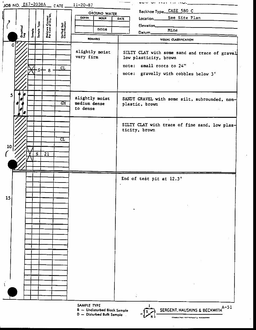
slighrly uoistvery firn
SILTY CLAY with some sand and rrace of grav6low plasticicy, brown
note: sroal l rooEs to 24"
note: gravel ly with cobbles below 3r
slighrly moistnedium denseto dense
SAI{DY GRAVEL eith soue sllr, subrounded,plast ic, browr
SILTY CLAY with crace of fine sand, low plasticity, brown
CnOUr.rO WAIER Backhoe Typg CASE 580 C
o€Prx HOUE OAIE
none
SATVIPLE fYPEI - Undisturbed Block SamplcD - Disturbed Eulk Srmple
Locali See Site PIan
E n d o f t e i t p i t a t 1 2 . 3 '
I-ffir SERGENT. HAUSKINS & EECKWITHA-51
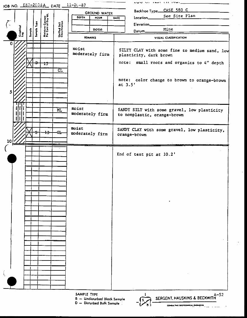
,OB NO. ES7-203SA p46
(,
I I -2r-a7
GROUNO WATERD€PTI{ lrout OATE
none
t v g 9 l l L J r I l a r ! v .
Eackhoe Type CASE 580 C
Lo.atior,
z{, . o. : o
I l i n aDafum
SAIIDY CI.AY withorange-brown
soEe gravel, low Plasticity,
vrsu^r ct^lslflcAtloN
lDoistmoderately fj.ra
SILTY CLAY with sone fine to trediutr sand,plascici ty, dark brown
note: saal l roots and organics co 4" depch
not,e: color change to brown to orange-browra r 3 . 5 '
uoistuoderacely firu
SANDY SILT with soue gravel, low plasti.cicyto nonplastic, orange-brotfir
Doi.stmoderately firn
End o f t es r p i r a r 10 .2 r
SA,lPtE TYPEI - Undisturbcd Elock SamplcD - Disrurbed Bulk Samole
A-52SERGENT. HAUSKINS & BECKWITH
I-m,eoalE GE<tTEOC4 Cr€.aCC
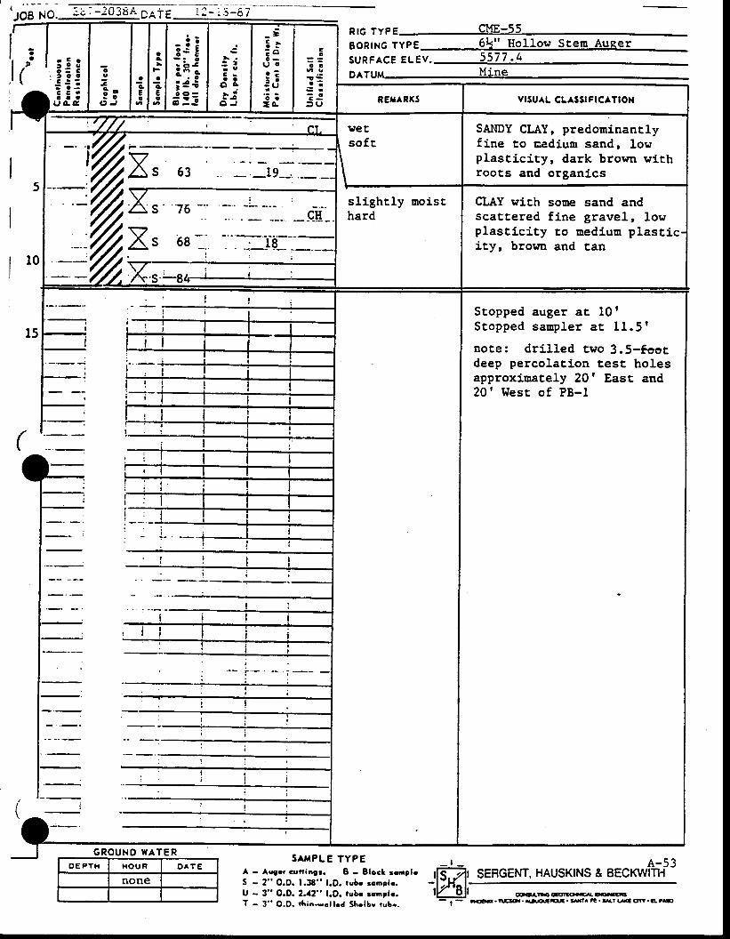
tJ;; No- :r -:0384 pAiE lI i t-'s'
r E o
3 :3' t a a
: i :c c .o a a
u g c
aa
I
\
nrc rvpeSBoRtNc TypE 6L" Hol low Scem AugerSURFACE ELev. 5577 ' (+
DATU
SAI{DY CLAY, predourinanrlyfine co aedium sand, lowplascicity, dark brown withroots and organi.cs
sl ight ly moisEhard
CLAY wich sone sand andscattered f ine gravel, lowplasticity to nediurn plastity, browa and can
Stopped auger at 10 t
S topped sanp ler a t 11 .5 f
note: dr i l led tvo 3.S-foocdeep percolation test holesapproxj.nately 20' East and20 ' West o f PB- l
G R O U N O W A T E RO E P t H H O U R D A T E
none
SAI{PLE TYPEA - Augrr cuni6!r. I - Elocl rcnploS - 2" O.D. 1.38" l.D. rsb. rcnrlo.U - 3" O.O. 2.a2" l.O. tubr rmplr.T - 3" O.O. i lr ia.rclled Sholbv rubr.
I SEFGENT. HAUSKINS & BECKWITI{
coatrFS oaolto.cr cr€..aCt
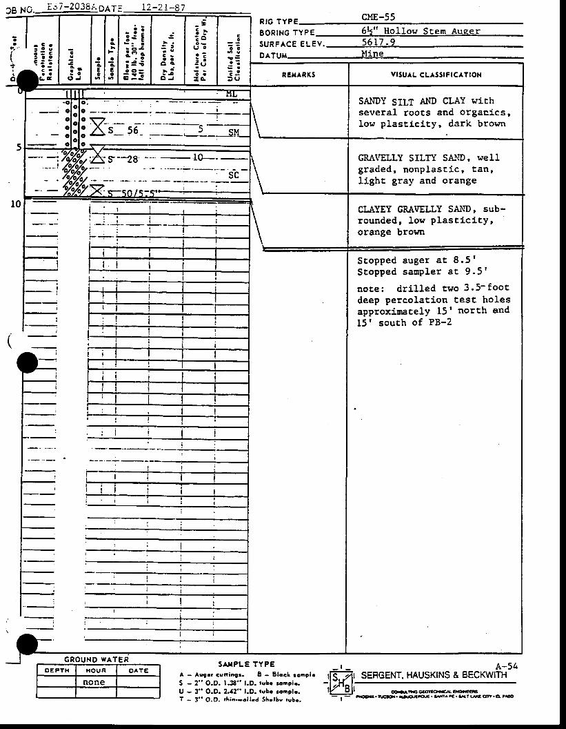
39 p6. ic7-29?8a9a1s 12-21-87RIG TYPE clrE-55BORING TYPE 6L" Hol low SEem Auqer
a,l.z
2
SURFACE ELEV. 5617 .9Co
c
aca
totC
a
cc
ac
D^TUM-
t t
! . i: .
G R O U N D W A T E R
O E P T H I{OUR OAtE
none
s TPLE TYPEA - Auger cuniagr. 8 - Slocl ronplrS - 2" O.O. lJ8" l .D. tobe rcnclo.U - 3" O.D.2.42" l .D. rcbe rcnglr .T - 3" O.O. rAio-rcllcd Shclbv rubc.
A-54SERGENT. HAUSKINS & BECKWITH
VISU^L CLASSIFICATION
SANDY SILT AND CLAY withseveral roocs and orgaEics,low plast ic i ty, dark brown
GRIVELLY SILTY SA:\D, wellg raded, nonp las t ic , lan ,light gray and orange
o v. \ t - - F
: As- s6-
. l
; s-28 l0---
CLAYEY GRAVELLY SAI\D, sub-rounded, low plast ic i ty,orange brorn
Stopped auget aE 8 .5 fScopped sanp ler a t 9 .5 r
no te : d r i l l ed two 3 .5- foo tdeep percolat ion tesc holesapProxiuBce1Y 15f north and15' south of PB-2
oo.llEa oao|to-r cxncclla.e'ar.l\G5r. {r.O.aE./€. 5^.C. !\t lsA Cn.O' t O
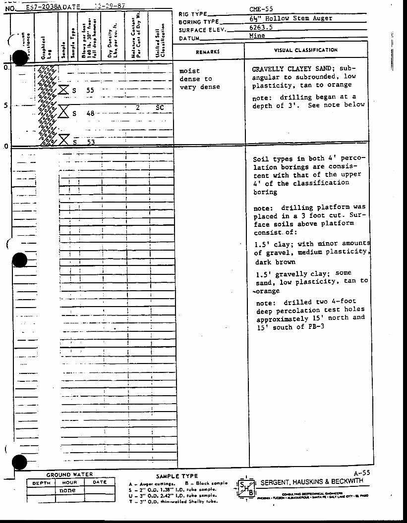
XO EST-2038eOel= cuE-55
' : !: 3
-. :
o
1 o= o
0 J
acE0
6
aA
aAEo
3 j i:i;; 3 io o =
; : J
: 6a a
o a- i; i
O J
_=E}: ou oo ?: a: Ut := G
C- 3o o
r ZS r
t J3 U
RIG TYPEBoRtNc 1yp6 6k" I lo l low Stem Auger
S U R F A C E e U e v . 6 2 6 3 ' 5
DATUM UiNC
REX^R(S vttuaL cLatslFlcATlox
[loistdensevery
E O
dense
GRAVELLY CLIYEY SAND; sub-angular to subrounded' Iowplast ic i ty ' tan co orange
noce: drill lng began ac a
depth o f 3 r . See no te be low
0. !t fi/^y'o1iI1t
i
) < c q sZ J Y
) l-"- '6/,xyY: ^ 2 sc^/ \ a, .te
\i7< ?X
0-
l_rl=l-
l:r:l-l-
(
..-' r l i
: ! i, : . : i l
i r ! r l il i l l l l:-. ! i i a!l i r i i ir r . t l . t
: ;: l ir . . l li ! ! l_:_i-
i i : : ! l: ! ! l. ; : i i
Soi l tyPes Ln boch 4' Perco- |lacion borlngs are consis- Icenc wiEh that of the uPPer I4 t of the classif j.cation
Iboring
Iuoce: dri l l ing Placforn was Iplaced in a 3 fooc cuE. Sur- 1iace soils above Platform Iconsist. of:
I1.5t claY; wich uinor amountiof gravel, mediuo elascicicV'ldark brown
I1.5t gravellY cIaY; some Isaud, low PlasticitY' tan Eol
-orange I
note: drj-I led two 4-fooE Ideep Percolation tesc holes IapProxi.oatelY l5r norEh and I15 | souch of PB-3 |
III
I
FI : l I
l=t--_t-lt--t-It--t - - -
t--t---t-
GROUND WATER SArrPTErYPE - r - f . 55A - Aggrr Gsatinit. B - Elocl ronplo
S - 2" O.D. 1.38" l.O. rube ronple.U - 3- O.D- 2.a2" l.O. lube rcnPle.T - 3" O.D. r{ria-rclled Shrlby rubr.
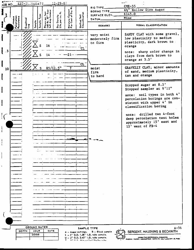
a a v , - - - : : - . . : - - : _
lOg NO__9S ;-z'- --.r aOl; = ! 2 - 2 9 - 8 , 1*-ss!. Id 'i€g
c
I
9 o: o
( , J
ag
€o
aA
JcEo
:ii:i;; 3 €f :=
? t
a oo a- ia 5
O J
=3 :; ou cr ?: :: U; :I G
Co
o o
a ' :
: l) U
RrG TYPE uf t - r r ,BoRtNG lypg 6t" Hol1ol t Scem Auger
S U R F A C E E L E V . 6 1 4 5 . 0
911gM Hine
€ : :. i E .l r a at a . E
RET RTS vrsu^L cLAssrFlcATlox
. 5
very moistmoderalely f i rnto fi.rm
\
SAI{DY CLAY with some gravel,
low plasticity t,o mediunplascj.ci.ty, dark brorm toorange
noce: sharP color change in
clays fron dark brown too r a n g e a c 5 . 5 '
='z,Xr- io - -21--
t0
.7/t:7/ lv
- .-
---!--- /,/,/. x s g5 / 1I .5" I moist
firu\ ro hard\
GMVELLY CLAY; uinor anountsof sand, medium PlasticitYrEan and orange
---- -_-.;---i-: ! l -
r!
(
l-=l-
trl-t---
t----:l=Ft--:
trl=Fl -
i i
l i
I I
i
q D , - i +
Scopped auger a t 8 -5 '
S topped samPler a t 9 '11"
note: soi l tYPes in boch 4l
percolacion borings are con-
si.stent with uPPer 4' in
classi f icacion boring
notb: dr i l led two - fooc
deep percolat ion test holes
appioxiuaceJ'Y 15' east and
15t west o f PB-4
S A $ P L E T Y P E A-56G R O U N D W A T E R
A - Acea cctr ingr. 8 - 8 lo6! rcoPlr
S - 2" O.D. 1.38" l .D. lubr rcnplr .U - 3" O.O. 2.a2" 1.D. tubr rooplr .t r . . ^ ^ . \ i - . . - - l l - l < l - l \ - . , . L -
SERGENT. HAUSKTNS & BECKWITH
a.tLr . tLcs.,r . rtilloJc ' 35^ tC . Ell !.{E Cfr ' a' ".*)

( i
oI
K4 0'l{
ct t$}h'o.
TEST WELL No. I
art^! 1\tt. uaa.atLa aoyr63 91.COaOJS .iO 3r.O. ..t,Orrr Clactt laaoi
TEST WELL No. I rcorurrNuEDt
acctor.trratc. taaof.r rttLy rrottfTttQtrnyav. tiot|! ro.ar|.f rrOC arOC3''G?ctrll?tY. rca^tc|'t tc. l?xctt o.q-aYC. {O{.:t tO 0.rr a!!,ttx gr.y
ll?Cl LtrGL rt rg.a tfF O. |-D-r,
Cgtrtfz'lg €a.gEl r.EOt ra o|^rgaalobr. SlLlleu.rtzt' la €r.!c5 !Ea? a.l lota rolrttilttf ca.ca {cotur cr.|<fa t - iCu.rt:tt[ CI^OES C|'t^r..l. t.rtlO ..C Orr.. Ca.t
ca.oft Lta3 rer?xgrco rrtiaor.
"cc35 O.utl?c arrxirv
rralSrt rcrxYft. !E{? t(rt|.t3 ca^vlcq-oyct^tc. rtaoor.|r^r.'|'t .r,|errTt
tFrF rV rfi|. fCtttr .xcrralt OF!"a, Ce.r tO a!.Cr .|.t'Gi,'t. r:Orl^arhlt
cr,.rl,ll|lS t63aacoofo rrtr cl-l.vw|i. O.ra ft5. raCCliu Oa^.ct - lt DOtSraaor
C. vCL
aea-trctatl
?trt
r'.oatttE tctr{vrl
EIt
E
.!t!rll rcr'aYrr. ^rx^rr?r. ,rr3.ir|c, Lrtl.r trtctttSo. rad?tt loElAt4trltLtatt ca/.y
axocil?l tdlrxtty- r.arEo tofa.Yr'?€tf rtlrC. tfl. rfEcr^ft|-t tc.tl{taGD.LEa?to|.oturacaY
-^o3t LrLt!. crlY
at^83 LAat 't/rrl-Elr aaorxar.oclt?t. ..|c.cEr"tlt{t-r|t. rG^rHtrGO.
9JltY. LafitoraDt1jtOrv
a(€tlt,aatl.aLtr.ta lrof,3t"C. rolrralrr|G.latrrEtto, crr"aY. r3otur to oltraa*a.
|.l?tl.E r6r6a1. tta...af?€. trE't|.Ylf.tHtltO. Ltc|{t crctir!.t Cr.r. ra?tt_ag DOC D t f"i
"U.F^ctO,rS SaDr{tx?3.
CI.'VEY
a^ots 'taa|.t3. ca^Y. cLrvl:'Clx?tzt?t. tit|.t. €*t Frr.r fO Ftf.E ca.rrao.
tli tO LtCr{.t Cr^y
^t6ttt xcratjroc
L^?t?l act-{Yrl
CU^.?Z|?E
cljvtroc
XEY TOWELI- CONSTRUCTTON
3'runrtol Catttl!r!t'! Clsr.a
a..ELEt t ta
O. lO F a9r{!
ltt rcrr cors?rrfiro srrcrt,cr?rc,rsFal 3.iO '.cr ra?tlv^!s.
LOG OF BORING
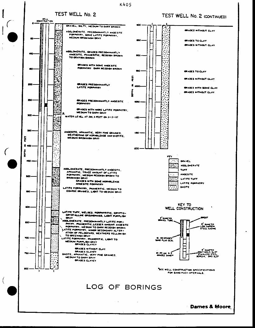
(
o
(
r(tr6fttir?|0r
KEO5
TEST WELL No. 2
gt.tt!. lrrv. rr:rrq ro osr la*i
TEST WELL No.2 (@NTTNUED)
^Catoatatt. ?aglxlmr|?l.y ^iE Snf"crittY.
ta.c L^t.rc toarYrt.racor,t atclr(a.r ea/ry
adLo.gar?t. cr.Cs 'tEoor.ri^i rt.vlrr3l'?:. ai^ratttt. atootSr ta*itO Ca^lt-{ at(ttr
-^r3 r,t|l tolS 11656a. trttxYt{Y ortr lggpa3a iaql
-ao3t ttcr.|,|.XTLYtjtm rcrr{rrr
l-/.4S rltE rraiTLt ^r.c3frEfgr'rlvrY
caoct rt?x t Glc tttttt ,oi?xtrY.raol,|a ?o c.|r ca^Y
rr?af t.tlc! .? ttr. t rt!? or '- t- 3t
li?i_!n'E: rrx^rrr€. rcrr rt.3 cr^i|€o.llft.crhc r r.c..r-^txr eno rrotrig.ICOarra atOr.t3,, Clrt
.a_olcrr?E. ticr..r^ra?|_y ^raoc3rrt.atxaaaf?.c. taact rIou,{t o3 LllrrG,€r,|fvtt. r.aot|.r| rtoorS. aaor( ro!l*it3. a^Y
c..ct rti. taaa aron LtxrEar.ocaftt tqtafYtY
L tt?t "ot
YFY. tt .rttr"|G. tf,orus roco^t3c c^r.to. LE}ft to ra9.rrr. ca^Y
ulrtlr''. rl:r.co. rriliavrrr. crvrro-crY'?rtlil'. cq,EAae. L3a' ar;Lt3f\ c/tY
^dl-o.Et.?c. ;r3F.rffiLt LArrG 'O_tiaytt, ataareart|c.!tt$t arq,/na? ^rr3tt!
\. rolrtavry. rctnr. tO ortr tcootll{ ararLa"r?E rcri{rtr. a.|rc|l lcc€r.o.,,l, ^LtGt-
rt|ot A tEl.u3t^rs. rctrxars tttlcsJ.\ tO ttctxrt.. clry
Ll?t?E ttrxr'tv. -.^.€lt?E. LOt? ?o*oxJU a'!}.t.|jr C..Y
rCttOat 4^Vfy
caoE3 ff?a.Gttt cl_lYAI.ofS Cr-tyat
olcttt. lrra^rrfttc. rttv ttrtG Gal|rto..aD||Jr
"o otrr cr^v
et^OCS 4^vat'
aoc -
r@-
Ert
rI
c^att:fixq,tt cr-.Y
-.oc3 to cr.rv-afi r|'|.crt Cr-^l
erott to Gl..Y
-^c3 f|?hqtt cr.rY
c.c3 r,?r telc c!.t-^r5:ttxqJ? c!^Y
EBa
EE
carr/tL
rc€!a.cl|"g
tt at
^r.ot3a"t
|.ltt?t tuat
LAtltS 'carxltt
o.cf"E
XEY TOWEII CONSTRUCTION
E - a .lro
lCt rtr-r- co{:ttrlctt€'r 3recr7|cry|Gb.37C 3.aao 'rcr tYtcava_3_
BORINGS
Gt-
LOG OF
Darncs & tloorc-
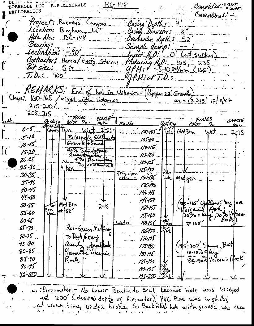
i jG lqg. ..&uy/Xrd-"'.,?Slrn
' Cqutq/tl"rt:
(rot.t"I
T - 7s'rn
| "- " ' ' f '10' ' 't-'-'1 1o-tf- -I ( /f.2D-.
t! -;:h,... g-sf ..
sf-fo. lo.rr
4f'rotr.tfSS'$oColfcf'70?o.l{ .-zf '7o90'Efgf-f o?o-t{
' ea,+S€
1:tS
L|-oClu+M;i,,r"AU
rq
Clr
lLQno -mh{/7t-t0
.-. rbttf- /gf-/to
sLzor''to- ,SZ
gg '
1$no'nk
yTrnfJ1{-@
^v
. . ?
.rs, .&*"*1**,- rV" I'I;tl*.lI{tA;i--G;;? holr ',^r,.s brrlTd
*r! ?oo' ( &:il"d ctp.S d Q;rz*.{.'} pva prer was \nsLtfud,. ,.,^i uktt .{ i,-r.r., bri.lgl t=;r{r, S" &*Lirfto}-Ut" r^ri.ft^, trrorrl-j LLs *us^
J \ t r i L - r . r . g
, ^ I - - | , r d ,
; tcrrvr---._!
I J-ZrlgEI lGra"elI f e'tET
{#Ic-'-
Ivled Brn*l'sz'
to-?*t ,&r&A,.&rH;l
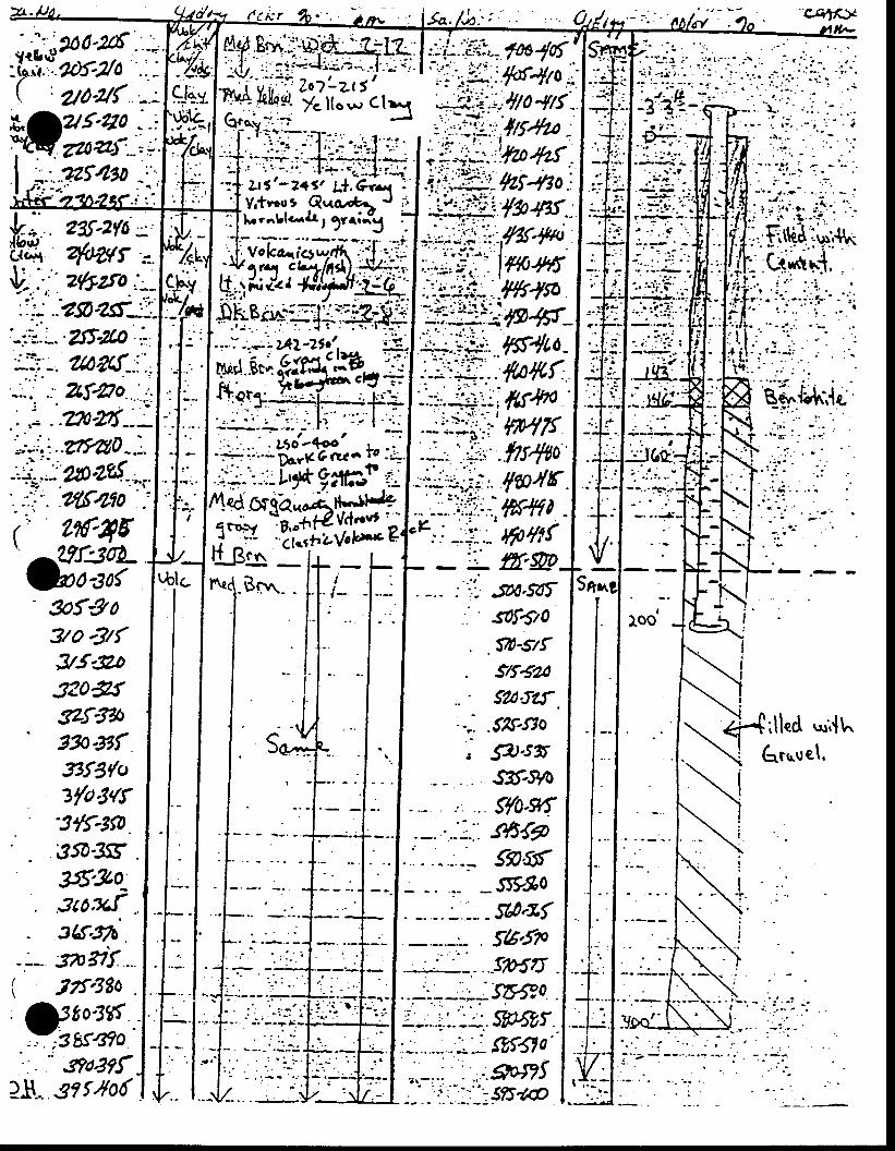
f tk r
- - . - ' . { .1:3. . : ' : i .
i i1 . r l
itit:
--,M-
. : a
:J'6t', J 1 ; -
--. . . . :J.
( l{-16'6t:t?' 9f9o
7o -3K95'go320&fszttT' 7fr-Rf
. 5DA.5A,' sof€/o.90-srfs/t5asa0.Jtf, .
.52&s7ow.s5slt-ryo
. S{o-s*f
E - r
*,{t^6,t,^uet.j3f3{ct
7{ct3'{f'3tT-3t0.
3sD3gU5'303cox.{
. 3Lf.th .-:. stuif .( nragoj"i'{,:
s+5{?5e-ftr
_s5?905t0.af56.5P
:
. - 3?8?r2$.... s?f'{06
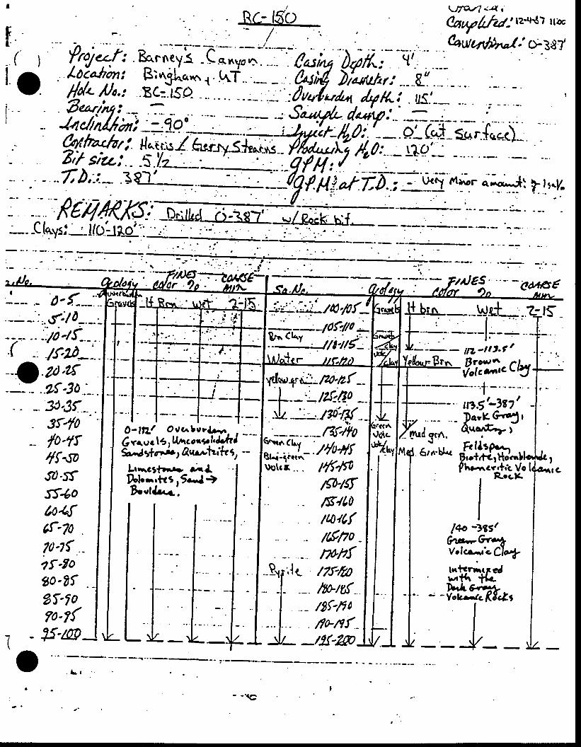
\)7Vl <4 t'(au7/rhz: rz'rt{? rtir(autuvLl-/.' c>-387
I
f. ( )lai_
'(:''-t'ii'i:l
9;:;, t- 3c3f --' 3r4o
lo-tf4f 'soJt''5.fSf'6oto4fcf'707o-t{ .?fEogo-Ef?f-f 0?o-{
i - 1s'/@^
v
v*Iygnc. m*(---l-_-- /?-f:O:o _.rL._': ..tgo.Rf ._
^Jet "- -eus€
- l : - : - ",ttr.f '
::,.clJt -"--- -; t-)8?'u&*3t'€nr I
Ph1 ,,/77,40
Lirrctr\r01s
f-b* --r'-tl.---- tt7
f9,fiF:;;k,;; 8i'ra e,l-ut* fi
O-ttZl Ovcrbcr&,!t. , _-_6vruc 15, lfnccr.*.1',Jc/l Jgrael6bre,u*inJk1 -
L.*.rt-r- ;1Dlor.tri .9.-l th"t{r..t'.
-I-llt- lwrGi.i.. . /ff.$o
'+irHor.llacrrfrL Vo
I *"*
I/Ehlsf/g'/t0/4rLr
' /Lft7o -tph{
I tqo 3ss/I Ov.--k4I v.lcr-.'c. CWII t.tcrnuall' sttr *{o
i '-v.\n%*,:lr /7t-/t0
. -l- .-. rbrtS.- /8f-lr0
tfo-nf .
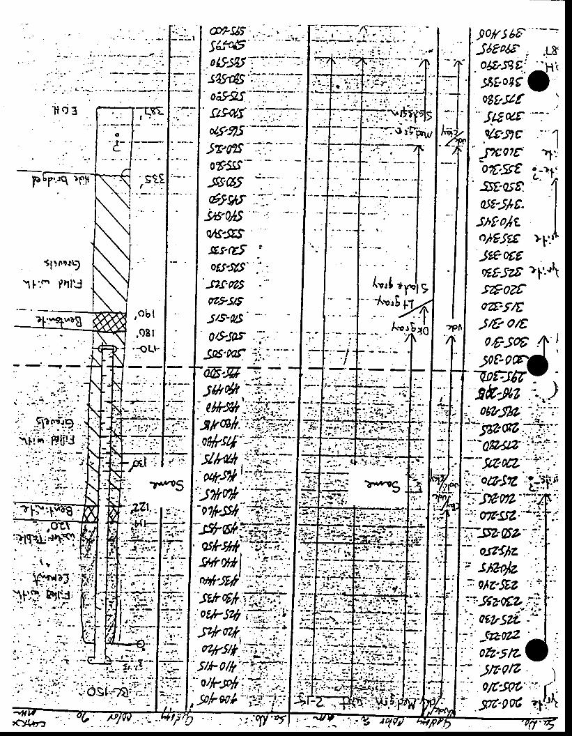
A"t
9o/ts 6FJ68qEA ;0$159q:
58t0gc IoSt s/t- JuwW'8c
JZo?toC'Sst-Btar8d5t'5r+t-shr-oltolgSEeJtE ot6
F .q )fl
5l)oD.!9
1l:(. Prll:J
,'B
oes-s:/s' ..-.Jzs.ms7?,95/5
S/S-0/S' -'
6-EF =.-ltr& f:i
-ek6l,
w-flz| >l:u\("rl ty.'f
" -Avit H_
,ob lA'181i1 T{1
08
t' 9 zt
:.
; . -
1 : i i. :'.';.
1 ' - .
t : ' - -: -': .r'
'|-tgtz''i
o9{lz? stuo/z
1.
'c'{.aa
0rz-5t7
APPENDD(B
BASETINE U/ATR, QUALITT DATA
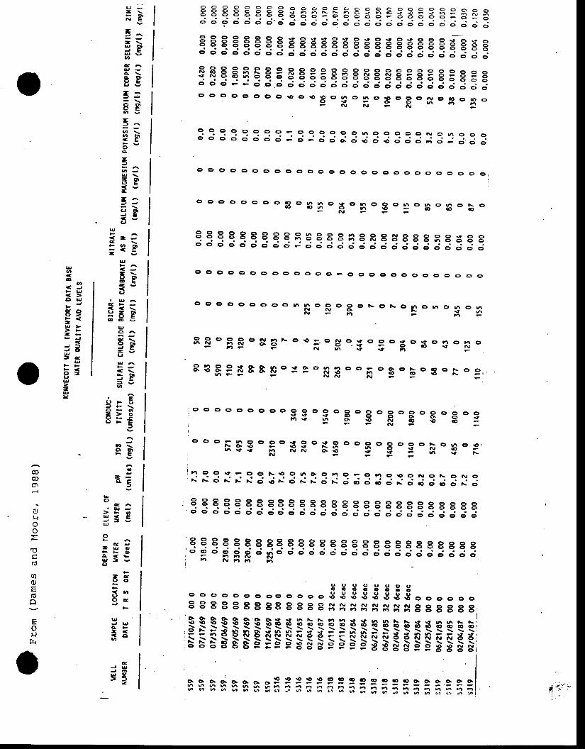
o o o o o o o cr o cr c) o (t o c> o o 0 G' 0 0 c, o €, e e c)
9 9 O o o o c r o rd - ' o ' d ; ; ; : : : : : : : : : : : : :3 : : : 3 : :
qq eq qq88qqqq88B8R8s888s8 3 3 3e; d c; d d d d o' o' - ' d d d d d ; d ; d ;; ; I d I ; ;
c o o o o o o o o o o g ? o c , c o S o e c o o o o o oo o o o c o o o e h h t s t ; . h 6 i - n c 1 r $ = > - ; ; H r y ao o o o o o o o 6 c r i i _ o d 5 6 b
; ; F ; : ; ; - : ; ; : ; ; ; : : : : : : : : : d : d :
q q q q q E E E g EEEEE E E EE gg g E E'E E Ed d d d d d o ' o ' ; d d ; d ; d ; ; ; ; ; ; ; ; ; i ; ;
qEqqqEEE 8EEEEEE8E8EEE3E3E3 Ed o ' d J J d o ' d ; ; d ; ; d ; ; ; ; ; ; ; ; ; ; i ; ;o o o c ' o c ) o o r o o . p o 3 o
H - E o F o s o S o
F o
c o o ct o ct ct oo c, o c) o cr o o c,- ;Y - ; -F -EOFOE 'EOEO3F f t p \ o E ' =
o ooFggof ' rs 'xg'oEog'goF o€' :AJ
: : 3 : : : ;? :: 3:: 3: : ; 3 I : :3i: : 3::e q q q e E a 8q q q q q q I I I r I I I I I I I3 3c; c; c; d o' c; c; dd c; d c; - ' - ' ; . ' ; ; ; ; ; : ; : i ; ;
u - -- \;E5^- \3Bo
A \* E 'E gJ -
e l PV E
5^?BoA
5
EB-r ^. + 9= go
U( l r4 \
a ! 4 q |= - g
g
6 ;6 E
C'
< < \
:EEgO ^
6 ;Egg
} P5 g
3r€O - 6- > oE ; f
5
A
U I \o bF E
I
- -o . C
3
oC ^
JH ;- 3SgU
oF
Q v- u 0F F I ,
A < !p I vCI
F
65Fqc u,(Jc , E
F
u,J UC F- << c t
EJ UJ Q
s5-
@
ofJ
r0
ordo
orjt&
o C ) o o o o o o g o g n o H
o n o 3 c , I o B o 3 o E oN
O O Ct Ct Ct Ct O O ct O Ct et O F O E Gr ct Ct ct O C, O O C, o g
Ct Ct O O g g O O .5 |'r n o !? G) g c' ts c) r\ c| t^ ct tr o| h o 6N s g - : - - - . -E -5
9 9 O c ) o o i r h ih - - F F
- ; F -
o . i . oH o .E . 3
oH o3 o 3 o !
o
t €F:FB&E' : eoFF -oF og.Eo3 o r . : ,
U
.DU'
< . JF g
O l g
ca c)9 -F a (-> F- -J 5J OUt a
U
F <o tIg--g
L
q q q q q e q qq q q e q E E q I I I I I I I I I3 r- : . F $d " $ t
c ; d d c ; c ; c ; d d dd ; ; ; ; ; d ; d
E3333gtso c t o o o . o o o o o o o € 3 € g 3 g € g o c , c , o c , c ,t I t I t I I 88 t I I B s S s H H H s g I I I I I8 ;
3 333 3S3 g* *_aF i ! ! t { e aQ! r { Q Q QQ,i t E p P S F FS S F F F F a F xt F F g B- S S r- n- B- SrB B- B- B- B- B- 3- is- p- 8- g- g- e- e- s'e- 5 5 s= E5 E 5 5 F *-;I
II
ts E S S A S A r;;;;;;;;;;;;;;;::;;i
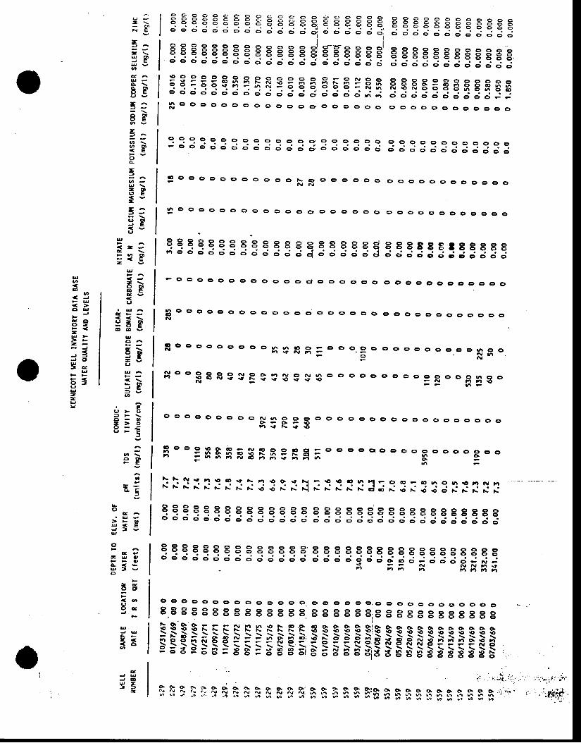
:i: i ieq e € eq E g E, €e e EEE EsEsssEEEsEEo e - o o o - e ; d c ; c ; d e ; " , { "
c ; c ; d c ; d d ; ; ; d d ; ; ; : ; ;
qEEqEqEEqEqEq EqEEqEE qEggEEggggEBd c ; c ; d d d ; ; ; ; ; ; d d d ; ; _ . ; ; ; ; : l I ; d d d d d c ;
_ 9 : : : ? ? q ? ? o o o o o o o o q 9 o 9 o o o o o o o o o o o- o o o d o o d c ; c i c ; d d 6 ; d d d c ; d d ; ; ; ; d ; ; ; ; : :
€I;qEqEqqEqE EE EEqqEfi E€EB3E8FgF88d d d d d d d d c ; ; ; ; ; ; ; ; ; a ; ; ; i : l i ; d d o . d ; in o o o c r o o o o o o o o o o o o o o o o o o o o o o o o o o o
qqqqeeqEqqqeqqqqqqeq eqqqsqrEqEEs; d d d e ; c ; d d d o o o o q o o o . j ; J ; ; ; ; : ; ; ; ; l ; ;
qqqqqeqEe r88 88 8r 88q8E8888r888888d d d d d d o ' c ; c ; ; ; ; ; ; ; ; ; d d ; ; ; ; ; ; ; ; ; ; ; ; ;
qqqqqeErrE I 8r I Br I qeqqqqqqqqqqqqEo d d d d d c ; c ; d c ; c ; d d d d e i e i o 9 o o o < , o - ; ; ; ; : ; :
; ; ; g ggB ;
3 o o o o o o o o ( > o o F g o o o o o o c , o e c , < , o o o o o o o
3 O O o o o o o o o G r o o c , o o c , o o c D o c r 0 o o o o o c r o o o
e ct c, o o cr o o c) o o 0 0 c, o o o o c, c, c, 0 0 0 0 c, c)o o G, c, c,
q o o o o o o o o o o G) O O o c, c, o O 0 o c, o o c, G' C' c' G) G' L O
t ! o o o o o o o o o R 3 F g = o o o .g o o c , o o o . ) c ) c , o 9 ! o oo l! h
!Y O O cr c) o o N o q 6 ry O N .4 0 0 0 0 I Gr O c' c, o o c, o o h c, c,3 6 * o o E - s G g . i 6 - - F N i r n e
n F
o o o o o o o o o g p t p g o o o o o o o o ( > c r c ) o c , o o o c r ot'l \t t\ rt rO
gl o o o 9 e o - 6y !o o o io o - cr er o cr ero o e, o ol i = ! 4 o 6 o g E h - F 6 = - - h= - b ' t N o n n € n r ' r 6 o o o 9 g E o o
6
\ \ ^ , . t F t r O O 9 a \ F 6 6 { N F € € 6 6 E r^: t ' i i r : : : : : : : :x: : : : :3; : : : :3: : : : : :
O Ct Ct O Ct O Gt O O C, cr G> O O' O Gt Cr O O O,O gr 6r g, e, e, c, c, G, C, c, O8.8 t I I I t B I B I I B r ' I t I r t 8; t t a a s c s t t t I teReQrrr t !!*Fs s 3 = =i$$$$FF$g$i$$$FFSqi{Q€t=irQ€::ei:83968=8ts=BSBEi Bag
:i- ;'r'i :;1
"
'""
R 9 9 i I q q o G 6 o o . G o r . o o . > o G > c > t 6 d a a a -: r : i : a; I : f i l g t t f I T, 5 5 n A $ f i '$f i $ i$ $f i$;q Be * ' : , ' : , ' ;
u '-)
- \; g
5^- \5 g
e c tO F6 v
r ^8B
5:?Foa.
5
AB-5:3B(,
U
( ! ;
> q 6- < e-U
- \g P
C'
: 69E E v
E
c \9 q '- e
L)
: P5 ga
. Eo > q) F \o - o- > ov - E
9B
o- -o 5
o
> F O
3 i5u
oe e
- u . ,F F O
u t vo
- Ec, ct
;< . aC'O a
UJ UA FI << c !o
U
oo
< , JF U
C ' U
e 6c r -F < (-> F- -J fJ C 'Ut r
UF FF <o tL)r-zg)<
c
J @
YE-
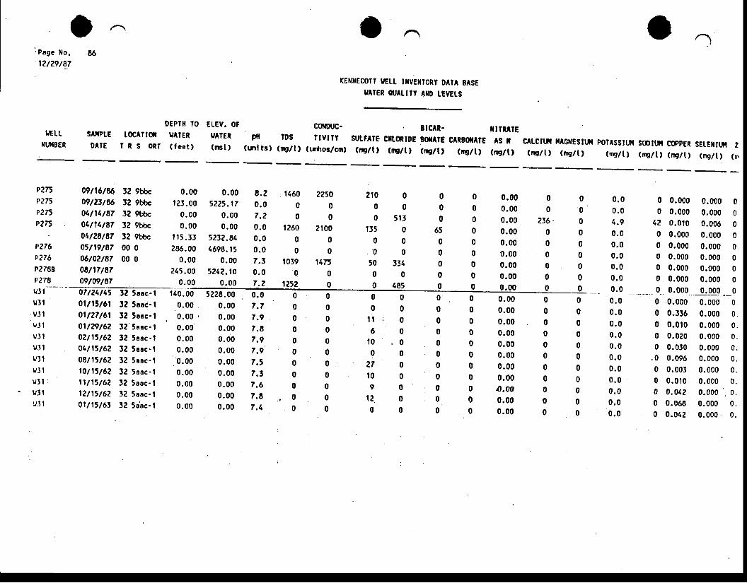
i Pege [o.
12t29/87
IJETT
XUil8ERsAftPtE loc^TtoflO A T E T T S O R T
DEPTI TO EIEV. OF9AIER y tE[( feet , ( rnst )
rE[[EColl uE[! mvEilroRy DAIA BASE9 rEn ou^Lnt anD tEvEts
Slc R- X I TRATEpfi rDs lrvny slrLi^t8 ciltontDE BOnrE CARBO|IATE AS I(tnlts) (ng/t) (tdros/cm) (rE/t, (l 'E/t, (q/l) (mg/t) (mg/t)
c tcltfi HAGltESltfi pol^sstu!,t soDttH coppEn sEtEntut z(ntg/t, (ntglt) ( i !g/t) (nElt) (r,9/ i) (rE/t) (m
P2nP275P27tP2n
P276p276
P?788P278
0 .00t 2t .00
0 .000 .00
f i 5 .33286.00
0 .00215.00
0 .00
0 .005225.17
0 .000 .00
5232.841698. t5
0 .005242.1o
0 .009228.00
0 .000 .000 .000.000 .000 .000 .000 .000 .000 .00
2?5000
210000
147500
0.000.000.000.000 .000.000.000.000.00
09116186 32 gbbc
oglztl$ 12 9bbc04t11t87 3? 9bbc01111187 32 9bbc04128187 12 9bbc0rn9/87 00 006t02t87 00 008n7t8709ts9t87
8 .20 . 07 .20 . 00 . 00 . 07. t0 . 07 .2
2 1 0 0 00 0 00 5 | ] 0
t35 0 650 0 00 0 0
50 3t1 00 0 00 1 8 5 0
116000
t26000
10390
1252
00000000
000000000 _ -00000000000
00
236.000000
0 . 00 . 01. .9
0 . 00 . 00 . 00 . 00 . 00.0 __ *-_0 . 00 . 00 . 00 . 00 . 00 . 00 . 00 . 0 .
0 . 00 , 00 . 0
0 0.0000 0.000
12 0 .0 t00 0.0000 0.0000 0.0000 0.0000 0.0000-- 0.000.0 0.0000 0.3360 0 .0 t00 0.0200 0.0t0
.0 0.0960 0.0030 0 .0100 0.0120 0.0680 0.042
0.000 00.000 00.006 00.000 00.000 00.000 00.000 00.000 0
_o_,_qgg _00 .000 0 .0 .000 0 .0.000 0.0 .000 0 .0.000 0.0 .000 0 .0 .000 0 .0 .000 0 .0 .000 , 0 .0 .000 0 .0 .000 0 .
utt ----
otnu|, 3iliaca 110.00ul lvJ lI,rJ IvJ lv t lrJl IvJ lv l tv t luJ l
01l15l6 l t2 5aac- l0 l lz f161 32 5aac. tUl8f t2 12 5aac- lOZl lS162 32 5aac. lOt,l l t162 32 5aac.l0811t162 12 5eac- l10115162 32 5ooc- l11115162 32 5aac- l' l2 l1 t l62 t2 5aac. t01l15l6t 32 5aac. l
0 .00
, 0 . 0 0 ,0.000 .000 .00
. 0 . 0 00 .000 .000 .000 .00
0 . 07 . 77 .97 .87 .97 .97 .57 . t7 .67 .87.4
0 0 00 0 0
l i i o o6 0 0
l 0 0 o0 0 0
2 7 0 0tooo9o :o
1 2 0 00 0 0
0 00 00 00 00 00 00 00 00 0
, 0 00 0
00000000000
00000000000
0.000.000.000.000.000.000.000.00o.000.000.00
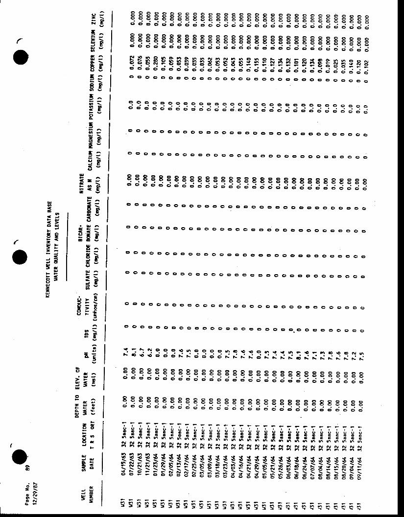
qqEqq€EEqEEEEEEEEEEEEEEEEE E gggEo - c ; d d d d d c ; d ; ; ; d ; ; ; ; ; ; d ; ; : : ; ; ; ; : ; :
qqqqqqEEEqqEqqEEq qqqEEEEEE E gEEEo - d d d d o ' d d d ; ; ; ; ; d ; d ; ; ; : ; ; ; d d d c . d d d
qEqEeqqEaEgEqEEgEE!iqFFEEsEEsFHd d c; d d d o' d d ; ;.' ; d ; o' d d .. -. d ; ; -. ; ; : : : : :o cl ct o o ct o o c) c) c, .:) o o o o I o o o c, c, c, G) e, c o o €| o c,
I 9 e q q o o o g g o o o c) o (r o cr e o o o e oc ; d d ; ; ; ; ; ; ; d : ; ; ; ; ; ; ; ; ; ; ; : : : : : : : :
33333:3:33333::3:E::::3:::3::3S
o c ) o o o g o o o o c o o o o o o o o o o g o c r e o o o o o c l
o o ( : ' 0 0 c ) 0 0 0 0 c o o o c o o o o o c e e , o c , 0 0 0 0 0 0
I O o cr o (t c) o e o o (f o o o o o o o o cr a:) o o G' o o o o c, o
c ) o o o o c r o o o o o o o o o o ( : ' o ( , o o o o o o o o o o o o
o o o o o o o o o o o c c o o o o o e o c r o o o c , o g o c ) o g
o c t o o ( > o o o o o o o o o G ) o c ' o o o o o o o o o o o e o o
c, o o o ct o o cr o o o o o o o o G' o o c' c, o o G' e, c, o o o o o
g o o c, o o o o o o o o c, o e o o o c, c G' (f-o o e, c o o o o o
:;: i3:3::3::::::: : i::::::::::;:qqqqeeEEqqqeqqEBqqeeEEEBBEEErEEd d d d d d c ; d d ; ; ; d d ; ; ;
" ; ; ; : ; ; d d d d d c ; d
qqqqqeEsqqeeqErEqqqEEBEEBErErrEd d d c; c; c; d d d.. ; d ; d ; J ; ; d d d d d d c; d ci c; d c; c;
777 ;?T ; : r r : = : : -;;;;;;;;;;;f; f ;i;I;;I; j; jili;;;'qggggsggHggggggggggggsgsgsgsggsg
x3333RI!p ! $ $ $ $ $ $ _QIt{{ { { { { { r { { {rF S FF R $ 5ni-Q-e FFF-F-€- F & p F F ts p x E r : e R B =s- b- s- =- E- E- s- B- != g' a= 5 e' 5 5 5 S 5 "-
.- 6 S S 5 S ; =- B- $ ; ;
Fs gFFFFiFEEE!!EFE!FiEEEEE EaEEa6
a ) -- \FB
E:- \3gUI
C I A
gg5:8g
5:?EoA
5
Eg-3:3gC'
t , -
?sI'
- \rgE v
C'
6gE Y
g,C ! A
t \9 A= gC'
< \5ga^
E> ( ,
> o;E
9g
3'
- -A C I
r'
o
lt
E
-
ae.
C'
.D
C'Do-C'
IJa
!oU'
r ( J
O r !
5eF . (-ar, >> FI r
J U
H-g
F <I tg--pv
(
o
oc ^
> > o
ssgg
o4 e
- u oA < $s r t vo
- eo c t
.E U,
t -
g,
A F- <; o
c
J G Og5-
o c o2 \
o.c , r vt ' r \o a\J
A e
(
-'vB

o1rExtEcotr tGlt ntrGxroR? DAIA BASE
U TER ot^l t rY AID tEVEtS
oaPsge lfo.
12t29t87
UETIltt r{8ER
s^'|PtEDAIE
DEPIH IOtoc^ilor u rER
r n S o R t ( f e e t )
EtEv. 0F coilDUC-v rEn pfl rDS ttv|ly(nst) (| '1its, (ng/t) (urfios/cn)
BtcAR- r trnl tEsut_FAtE C[toRtDE Boil^lE CARsOtAtE ls x(ttrg/i, (nElt ) (nE/t, (mslt, (qr/t,
c^[cruil ilAGilEStUil pollsstur soorut| 0DPER SEtEltni il,rr(mg/t ) (nglt ) (DS/t ) (rQlt ) (rE/l ) (,,'9/1, (rnql r
r{ttu3lt,Jls3lt l tvttuIv3lvJlvttr4tlu3tv3lr{ttr{tlvllr{tlr{tlr{ltrJllr{tlutlr{ttytl|aIuJlutlvJlul lvJlv31
0 .000.000.000 .000.000.000.000.000.000 .000.000 .000.000.000.000.000.000.000.000 .000.000.000.00o. oo0 .000.000 .000 .000 .000 .000.00
0.000.000.000.000.000.000.000 .000.000.000.000.000.000.000.000.000.000.000.000.000.000.oo0.000.000.000.000.000.000.000.000.00
0 . 00 . 00 .00 .00 .00 .00 .00 .00 . 00 . 00 . 00 . 00 .00 . 00 .00 .00 . 00 . 00 . 00 . 00 . 00 .00 .00 .00 . 00 . 00 . 00 .00 . 00 . 00 .0
0et18t6109t2tt&10t01t64t1to l t&12t01t640t t15t65o?t1tt6503ntt6,04t1rt6505t1tt6,06/trt6t07t15t6508/ttt6509t15t6510n5t65l1nrt651?t1rt6501t1r t60?nrt66ott15t6604t15t605t15t6607t05t6609t07t6610t27t(611t tgt612t20t66
. 02to2t6702t2tt67ot/17t6704/26t61
l2 5aac- l32 5aac- l32 5aac- l12 5aae-t32 Jaac-f12 5ooc- l12 5aoc- l32 5aac- lt2 5oac- l32 5aoc- f52 5aac- lt2 5aac- l32 5aac- l12 5aec- t32 5aac- i32 Saac- t32 5aac- t32 5aac- t12 5coc- l12 5aec- lt2 5aac- l!2 Saac- lt2 5aac- l12 5acc- f32 5aac- l12 5aac- l!2 5aoc- l32 Soac- l32 5aac- l32 Soac- l32 5aac- l
0.00 7.60 .00 6 .60 .00 7 .30 .00 7 .70.00 7.40.00 7.40 .00 6 .50 .00 7 .10 .00 7 .70 .00 7 .90.00 7.60.00 7.60 .00 7 .50.00 6.80.00 7.20.00 6.70.00 7. t0.00 7.90.00 7.90 .00 7 .70 .00 7 .80 .00 7 .90.00 7.80 .00 7 .80.00 7. t ,0 .00 6 .30 .00 8 .00 .00 7 .80 .00 7 .80 .00 8 .00 .00 7 .9
0 0.0950 0.9020 0 .1000 0 . t 580 0.0530 0.0000 0 .1?00 0.0500 0 .1820 0 . t 200 0.0650 0 . t 000 0.0010 0 . | ] 20 0.02t0 0.0740 0.00t0 0.0t50 0.0010 0.2500 0.0800 0 .2100 0 . i l 00 0.0330 0. i lo0 0 . t 260 0.0760 0.0700 0.0300 0.0300 0.320
0.000 0.0{0.000 0.0r0.000 0.0(0.000 0.0(0.000 0.0(0.000 0.0 '0.000 0.nf0.000 0.0(0.000 0.0(0.000 0.0(0.000 0.000.000 0.0r0.000 0.000.000 0.000.0q1 0.0n0.000 0.000.000 0.000.000 0.000.000 0.0r0.000 0.000.000 0.0r0.000 0.0r0.000 0.0n0.000 0.0r '0.000 0.0'r0.000 0,or0.000 0.0r ,0.000 0.000.000 0.0010.000 0.0010.000 0.00(
0 0 0ooo0 0 0ooo0 0 00 0 00 0 00 0 0oooooo0 0 00 0 0ooo0 0 00 0 00 0 0ooo0 0 0ooo0 0 00 0 00 0 00 0 00 0 00 0 00 0 00 0 00 0 00 0 00 0 00 0 0
0 00 00 00 00 00 00 00 00 00 00 00 00 00 00 00 00 00 00 00 00 00 00 00 00 00 00 00 00 00 00 0
0000000000000000000000000000000
0000000000000000000000000r000000
0000000000000000000000000000000
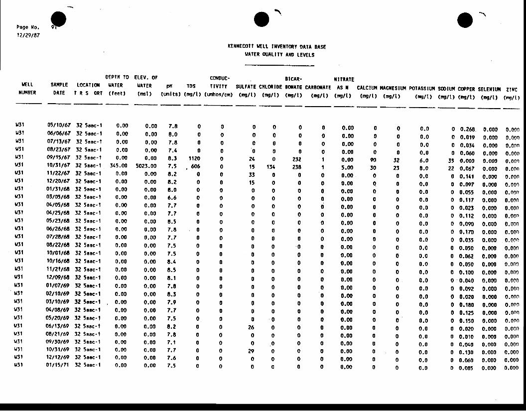
p O.rE[ilECOtt lGtt nfl/Eflloty 0AlA BASE
u rER oir^ulY AID tEvEts
E[EV. OF coflDuc- BICAR- XnRATEUAIER pil ros ilvtly sut^lE crtontDE 0ilArE cAREilArE AS X(ml) (tnlts) (ms/t) (rrhos/cn) (nElt) (rE/l) (rE/t, (ng/t) (nrs/t)
Page l lo.
12t29t87
IJETT
XI,I{BER
s^fiPIEDAIE
DEPTI IOloc^ltof yAIER
t R S o R l ( f e e t )c^tctut ilAGxEStrnt pot^sstut sotur copER SEtEfttil u txc(qr/t) (ms/l) (m9/t, (irg/t) (nE/t, (nrs/t, (r,9/t)
vllrlSti/JtnlIutlvtluJlvllu3let tv3lv:tluJlvltr{tllIJlr{ll|{llutlt/3trJltrJ3tItttt{ttuttu3tu3lv l te] lv3lu l l
05t10t6106twt6707ntt6708t2tt6709t|st6710tt1t671lt22t6f12t20t6701tt1t6€ottott6'804to't6ao4tztt6a0rt23t6a06t26t6,807t28t6a08t?2t6'|10t01t6'd10t16t6811t2lt6,c12t09t6'8ott07t6902/l0t69ottl0t6901t08t690tt20t6906t1tt6908tzlt6909ttot6910tt1t6912t12t6901 t15 t7 l
3? 5eac- l32 5eac- t32 5aoc- lt2 5aec- l32 Saoc-132 5eac- l32 5aac- t52 Soec- tl? 5aac- l32 5aoc- lt 2 5aec - t32 Saac - l32 5aec- lt2 5eoc- l32 Sacc-ll2 5aac- l32 5oac- l32 5aac- t52 5aoc- l32 5aac- l32 5eac- lt2 Saac- t32 5aac- lf2 5rac-t32 Sacc- l32 5eoc - t32 Saec- l32 Saac - l32 5eoc- l32 5aac- t12 l aac - l
0.00 0.000.00 0.000 .00 0 .000.00 0.000.00 0.00
115.00 5023.000.00 0.000,00 0.000.00 0.000.00 0.000.00 0.000 .00 0 .000.00 0.000.00 0.000.00 0.000.00 0.000 .00 0 .000.00 0.000.00 0.000 .00 0 .000.00 0.000.00 0.00
. 0.00 0.000.00 0.000.00 0.000.00 0.000.00 0.000 .00 0 .000 .00 0 .000.00 0.000.00 0.00
0 0.2680 0.0190 0.0140 0.060
3t 0.00022 0.0670 0 . t a l0 0.0970 0.0550 0. i l70 0.0230 0 . t t 20 0.0900 0. t700 0.0350 0.0500 0.0620 0.0500 0 .1000 0.0400 0.0920 0.0200 0. tEo0 0 . t ?50 0 . t 500 0.0200 0.0 ' t00 0.0100 0 . t 300 0.0600 0.085
0.000 0.0000.000 0.0000.000 0.00n0.000 0.0000.000 0.0000.000 0.0000.000 0.0000.000 0.0000.000 0.0000.000 0.0000.000 0.0000,000 0.00n0.000 0.0000.000 0.0000.000 0.0000.000 0.0000.000 0.0000.000 0.0000.000 0.0000.000 0.0000.000 0.0000.000 0.0000.000 0.0000.000 0.0000.000 0.0000.000 0.0000.000 0.00n0.000 0.0000.000 0.0000.000 0.0000.000 0.000
7.88 . 07.87.48 . t7 .58 . 28 .28 .06 .67 .77 .78 . 57 .87 . f7 .57 .58 .48 .58 . 17.88 .37.97 . 77 .38 . 27.87 . 17 . 77 .6? .5
0 0 0 00 0 0 00 0 0 00 0 0 0
2 4 0 2 t 2 ttt tl4 238 |3 3 0 0 01 5 0 0 00 0 0 00 0 0 0o0o00 0 0 00 0 0 00 0 0 00 0 0 00 0 . 0 00 0 0 00 0 0 00 0 0 00 0 0 00 0 0 00 0 0 00 0 0 00 0 0 00 0 0 0
2 6 0 0 00 0 0 00 . 0 0 0
2 9 0 0 00 0 0 00 0 0 0
0 00 00 00 0
t t20 0606 0
0 00 00 00 00 00 00 00 00 00 00 00 00 00 00 00 00 00 00 00 00 00 00 00 00 0
0.000.000.000.000.005.000.00 .
0.000.000.000.000.000.000.000.000.000.000.000.000.000.000.000.000.000.000.000.000.000.000.000.00
0 . 00 . 00 . 00 .06 .08 .00 . 00 .00 .00 . 00 . 00 . 00 . 00 . 00 . 00 . 00 . 00 . 00 . 00 . 00 .00 .00 .00 .00 . 00 .00 . 00 . 00 . 00 . 00 . 0
0000
90300q
00000000000000000000000
0000
t22t0000000000000000000000000
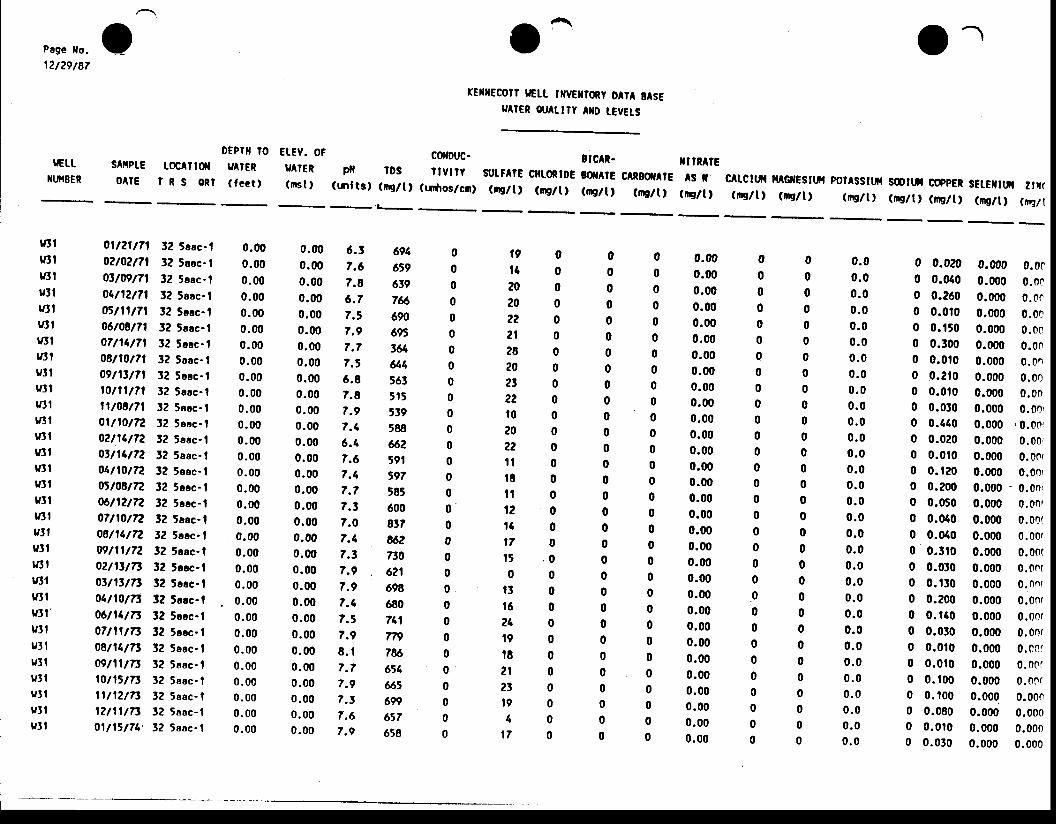
Page lto.
r?/29/87
uEttXt,IIBER
sArtPtE0AlE
oEpril totoc^ilil UAIER
I R S o R l ( f e c t ,
E[Ev. 0F co[DUC-luAtER p{ lDs IMt?(mst ) (inl ts, (mg/t ) (rrfios/cn)
o-TEIIECOTI |Gtt tflvEltoRy DtrA ElsE
eAtER orr^ttrY ilD t€vEts
ucAR- rnn^lEsutFAtE ctftoRtDE 8OtAtE CARBflAtE AS I(ns/t) (mg/t) (nglt, (rB/t, (,n9/1,
c^tcttfi il G|rEsrur polAsstufr soortil coppER sEtEfttfr zr{((qr/t) (rE/t) ("8/t) (iE/t, (,,E/t) (r,g/t) (rEll
t{tty3l
rl3lutlr{tft{tlr{ttr{llu l Iu l lnJlv:tlv3lr{llu3lvilytl
r{llrrtfvi lv:tlr4rr{ttvlt 'u3tv3trJl tultv3 lv3lv3l
0.000.000 .000.000.000.000.000 .000 .000.000.000.000.000.000 .000.000.000.000.000.000 .000.000.000.000 .000 .000 .000 .000 .000 .000.00
0.000.000.000.000.000.000.000.000.000.000.000.000.000.000.000.000.000.000.000.000.000.000.000.000.000.000.000.000.000.000.00
0000000000000000000000000000000
0 .00 .00 .00 .00 .00 . 00 . 00 . 00 .00 .00 . 00 . 00 .00 .00 .00 .00 .00 .00 .00 . 00 . 00 .00 .00 .00 . 00 . 00 . 00 . 00 . 00 .00 . 0
ott?rtTl02t0?t7l0ttogt7l04t12t7105tltt7l06t08t7l07t14t71o8n0t7l09nttfllonltTlll to$t7l01t10t7202n4t720tt14t7201t10t72o5to8t7206t12t7207n0t7208t11t7209nlt7202tIttitotnttftoLtlgtTt06t14t7307t11t73ogtl4t7309t11t7510t1ttTt1tt t2t7t12n1tTt01 t1rt74'
32 5aoc.l32 5aac- l32 5sac- t32 5aac- l32 5ecc-l3? 5aac-l3? 5esc- l32 5oac- lt2 5aec- l32 5aec- l32 5aoc- l12 5aac- t32 5aac- l32 5eec- t32 5aec-l32 5eec- l32 5aoc- l32 5cac- l32 5acc-f32 5aac-l32 Srac- lt2 Scac- l32 5acc-l12 5aae-l32 5acc- l32 5eec- t3? 5aac- l32 5aac- l32 5aac- tJ2 Soac- l32 5aac- l
0.00 6.30.00 7.60.00 7.80.00 6.70.00 7.50.00 7.90.00 7.70.00 7.50.00 6.80.00 7.80.00 7.90.00 f .40.00 6.40.00 7.60.00 7.40.00 f .70.00 7.30.00 7.00.00 7.40.00 7.t0.00 7.90.00 7.90.00 7.40.00 ?. ,0.00 7.90 .00 8 .10 .00 7 .70 .00 7 .90.00 7. t0.00 7.60.00 7.9
0 0.0200 0.0400 0.2600 0.0t00 0 . r500 0.3000 0.0100 0 .2 f00 0.0t00 0.0300 0.1400 0.0?00 0 .0100 0 .1?00 0.2000 0.0500 0.0400 0.0100 0.3t00 0.0!00 0 . | ]00 0.2000 0 . tao0 0.0300 0 .0100 0 .0 t00 0 .1000 0 . t000 0.0800 0 .0100 0.030
0.000 0.0f0.000 0.0c0.000 0.0e0.000 0.000.000 0.000.000 0.000.000 0.0n0.000 0.000.000 0.000.000 0.00r0.000 ,0.00r
0.000 0.00,0.000 0.00{0.000 0.00t0.000 0.00r0.000 0.onf0.000 0.00(0.000 0,.00(0.000 0.00(0.000 0.ont0.000 0.0n{0.000 0.00r0.000 0.00f0.000 0.00r0.000 0.cof0.000 0.0010.000 0.00r0.000 0.0000.000 0.0000.000 0.0000.000 0.000
6 9 4 0 1 9 0 06 5 9 0 t 4 0 06 3 9 0 2 0 0 07 6 6 0 2 0 0 06 9 0 0 2 2 0 06 9 5 0 2 t 0 03 6 4 0 2 8 0 06 1 4 0 2 0 0 05 6 3 0 ? l o 05 r 5 0 2 2 0 05 3 9 0 t 0 0 05 8 8 0 2 0 0 06 6 2 0 2 2 0 0t 9 1 s i l o 05 9 7 0 t E 0 05 8 5 0 f l 0 06 0 0 0 1 2 0 08 1 7 0 1 4 0 0u 2 0 l 7 o 07 f0 0 t 5 , 0 o
, 6 2 1 0 o o 0698 0 . t 3 0 o6 8 0 0 t 6 0 07 4 1 0 2 4 0 0T n 0 t 9 0 o7 8 6 0 1 8 0 06 1 4 0 2 t 0 06 6 5 0 2 3 0 06 9 9 0 1 9 0 06 5 7 0 4 0 06 5 8 0 t 7 0 0
0000000000000000000000000000000
0000000000000000000000000000000
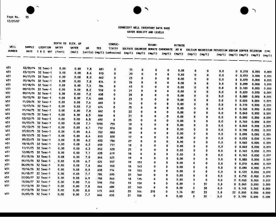
O- o\rE[IECOrl |Gtt tilrGrrony DAIA BASE
e TER Ot^urt ^ID tErGrs
frPage tlo.
12t?9t87
tGttxutEER
sAffPIc0AlE
oEPllt loLoc^ltoil y tER
I R S O n f ( f e e t t
EtEV. oF co0fouc-e rER pil tDS ilvtty(nsl) (mlts) (mS/tt (uhos/cm)
Etc^t- t t rMlEsuF^rc crtoRtDE BilAl€ c RBOffAtE ls I(ngli, (rnglt, (rE/t, (mE/tI (mc/t)
c^tcrtfi [AGrfEsrtil por^ssrur sortfi c(ppER SEr.Elttil 2f[c(n9/t) (nE/t , (rE/t , (qr/ t ) (qr/ t , ("8/ t) (nsl t)
tIJlu3ltftletlvl lrJ3 |UttIr{llvJlv:ttyttt
vJlITJIlf,t1I3t'yJl
i{tl16lvt1t{tlutlyJl
vJt
.v3l'v3l
1J3lv3lv3lv3l
r/3l
0.000.000 .000.000 .000 .000.000.000 .000.000.000.000.000.000.000.000.000.000.000.000.000.000.000.000.000.000.000.000 .000.000.00
0.000.000.000.000.000.000.000.(n0.000.000.000.000.000.000.000.000.000.000.000.000.000.000.000.000.000.000.000.000.00t . t 40.00
00000000000000000000000000000
820
000000000000000000000000000
3 t383!t0
0 .00 .00 .00 .00 .00 .00 .00 .00 .00 .00 .00 .00 . 00 .00 .00 .00 . 00 . 00 .00 .00 .00 .00 .00 .00 . 00 .00 . 00 .00 .05 . 00 . 0
02t20t740yl2t740t l l l1740stl6t7t,07t1ct7108^2t7409t11t?410t1il741l t20t7112tt7t?401t16t7502^9t150tt lun$tlttn05nttr'07t22t7508n2t7509tlttntott6tTtn t l l tnl2t09tT501t19tf604n5t7606tTrt?610t14t760t,118177oft?0t7?10t26t77ol | 12t780t tltt7801t05t78
32 5eoc- l32 5aac-112 5eac- t32 Saac- l32 5oac- ll2 5eac- l12 5aac- l3? 5aac- l32 Saac- l3? 5eac- l12 5aec- tt2 5ecc- ll2 5aac- l32 5aac- lt2 Saec- t32 Sacc- l32 5aac- t!2 5acc- l32 Saoc- l32 5acc- l32 Jaac- tt2 Scac- l!2 5cac- t12 5occ- l12 5aac- lt2 5aac- lt2 5oac- l12 5sac- l!2 Saac- l32 5aac- l32 5aac- l
0.00 7.80 .00 8 .60 .00 6 .00 .00 7 .80 .00 7 .50 .00 8 .20.00 7.20.00 7.40.00 7.40.00 7. ,0.00 7.00.00 6.50 .00 6 .80 .00 7 .10 .00 6 . I0 .00 6.40.00 6.40 .00 6 .20.00 6.20 .00 6 .30 .00 7 . 10.00 7.00 .00 6 .70.00 7.60 .00 0 .00 .00 7 .70 .00 6 .90 .00 7 .00.00 7.80.00 8.00 .00 7 .7
1 5 0 02 0 0 0? t 0 02 6 0 04 0 0 02 1 0 02 0 0 02 t 0 0t 4 0 0n 0 02 t 0 02 1 0 02 t 0 0t 9 0 02 0 0 01 9 0 01 7 0 02 7 0 01 8 0 02 5 0 0' t 8 0 0
1 9 0 019 t53 016 143 019 t33 020 t60 018 t75 019 t50 02? t40 020 144 2152 t t 50 0
68t 08 t0 066? 0814 07 8 4 0t50 0608 0668 0660 0674 0662 06 0692 0
f090 15,712 8t6762 8608t0 820602 7t!6650 7t l6t2 628638 619646 6256?4 597& 760638 71176 690700 t!40598 750646 680415 U.0646 630
0000000000000000000000000000000
0 0.210 0.000 0.0000 0.050 0.000 0.0000 0.070 0.000 0.0000 0.090 0.000 0.0000 0.t00 0.000 0.0000 0.020 0.000 0.0000 0.060 0.000 0.0000 0.020 0.000 0.0000 0.i l0 0.000 0.0000 0.t60 0.000 0.0000 0.040 0.000 0.0000 0.080 0.000 0.0000 0.140 0.000 0.0000 0.010 0.000 0.0000 0.t90 0.000 0.0000 0.090 0.000 0.0000 0.050 0.000 0.c000 0.060 0.000 0.0000 0.040 0.000 0.0000 0. t40 0.000 0.0000 0.140 0.000 0.00n0 0.080 0.000 0.0000 0.010 0.000 0.0000 0.080 0.000 0.0n00 0.120 0.000 0.0000 0.750 0.000 0.0n00 0.060 0.000 0.0000 0.040 0.000 0.0000 0. t40 0.000 0.000
22 0.000 0.000 0.0000 0. t90 0.000 0.000

OlPoge lfo.
12t29t87
IJETT
xuHE€n
DEPIil l0 Et Ev. otgATER UAIER(feet) ( rBt ,
xE|fflEcolr tGl_t_ mvElroty oAtA E^SEu rER ot^urY AilD lErGts
EtcAR-cofDuc-pll tDS I tvt ry
(tnlts, (rE/1, (urftos/cn)
lt TnAtEsArPtE toc^ltorlD A I E I R S E R T
suLFllE cfltoiloE oOlAlE clRoiltrE AS t ClLctuil lt^GttEstut porAssttil s@ttil coppER sEtEiltfi zntc(tnO/t' (ns/t) (nE/t) (os/t) (ng/t, (rw/t) (mg/t) (rp/t) (ng/t) ("relt) (rp/tt (rns/ll
taIIIJIy:tty:tt
etle51vllr{tlvl lutlvtlv3lr{nITJ Iy:tt
s3tu:tIr{tlrJStv3l
r{ltr{ttv3l
0.000.000 .000 .000.000.000 .000.000 .000 .000 ,000 .000 .000.000.000.000.000 .000.000.000.000.000.000.000.000.000.000.000.000.000.00
0.000.000.000.000.000.000.000.000.000.000.000.000.000.000.000.000.000.000.000.000.950.000.730.00t .00t.800.000.000.000.000.00
0000000
100000
99000000
1000
l800
92000
8285
t5t0
27363600
t l0000000000000
l l260000
3200000
0 .00 .00 .00 .00 .00 .00 .00 . 00 .00 .00 .00 .00 . 00 .00 .00 . 00 .00 . 00 .00 .0a.ti0 .00 .05 . 00 .00 . 00 . 06 .00 . 0
20 .00 .0
vttv3lu:tlull1l]tv3t
O8l0tl78 32 Saac.lO7l1ll7\, 3? Saac-lOTlll lT, 32 5aoc.t07ll1lf, 32 5aec-t021?418? 32 5eac.t02121182 32 5oac.l02121182 32 5aac.l02121182 32 5aac-l02121182 32 Soac-l02124182 32 5aac-l02124t82 32 5aoc.l02124182 32 5aac-lbztzqnz !Z 5aac-t0212a182 32 5cac.l02124182 32 5oac-l02124182 52 5aec-t02124182 32 5aac-l02124182 32 5rac-t02124182 t2 5coc-t02124182 32 5aac-l08124182 32 5aac-l0 l l l l l& 32 5aec- l0 l l l l t84 12 5aac. l0ll l l l8I. 32 5aac.l'0tl07l85 32 5aac-t0t107185 12 5oac-t10l23l8t 32 5aac-l10l2tl0t 32 5aac-l09105186 12 Sacc-l0tl1Ol87 32 5aac-lOtll0l87 32 5aoc-l
0.00 7.10 .00 a . l0 .00 0.00.00 0.00.00 0.00.00 0.00.00 0.00.00 0.00.00 0.00 .00 0 .00.00 7.40.00 0.00.00 7.40.00 0.00.00 0.00.00 0.00.00 0.00.00 0.00.00 0.00.00 0.00.00 7.90.00 0.00.00 0.00.00 6.50.00 0.00.00 7.10.00 0.00.00 7.10 .00 7 .10.00 7.10.00 0.0
0 0.0500 0.0000 0.0300 0.0300 0.0000 0.0000 0.0000 0.0000 0.0000 0.0000 0.0000 0.000
29 0.0000 0.0400 0.0000 0.0t0
26 0.000?6 0.0000 0.0000 0.000
a 0.0000 0.0000 0.000
!l 0.0200 0.000
27 0.0t00 0.000
34 0.02030 0.0t069 0.0t00 0.000
0.000 0.00n0.000 0.0000.000 0.0000.000 0.0000.000 0.0000.000 0.0000.000 0.0000.000 0.0000.000 0.0800.000 0. i l00.000 0.0800.000 0.0000.000 0.0000.000 0.0000.000 "0.000
0.000 0.0000.000 0.0000.000 0.000o.o0o 0.0000.000 0.0000.000 0.0000.000 0.0r00.000 0.0000.004 0.0000.000. 0.0000.004 0.0r,t0.00d 0.0/,00.004, 0.050
,,0.001t 0.010,0.004, 0.1200.000 0.270
6& 600 t9 120 0$ 2 5 5 0 t 6 0 0
0 0 0 0 00 0 0 t i 3 0
7 0 0 5 0 0 0 0 00 0 0 0 0
7 0 0 0 t 8 0 00 0 0 1 4 7 00 0 t 8 o o0 0 0 0 00 0 0 0 00 0 0 0 00 0 0 0 00 0 0 0 00 5 0 0 0 0 . o0 0 0 1 1 ? 00 0 0 0 00 0 0 0 00 0 0 0 00 0 0 0 0
536 799 27 l2' 2246 0 6 0 2 t 0 0
0 0 0 0 00 0 0 t 1 7 0
525 0 26 t6t 0,52t 1600 26 t65 0
5n 92t 2t 0 1900 0 0 . 1 5 7 0
1 9 t 0 0 t z t 00 0 0 t 6 t o
548 860 28 O too
0000000000000000000000000000000
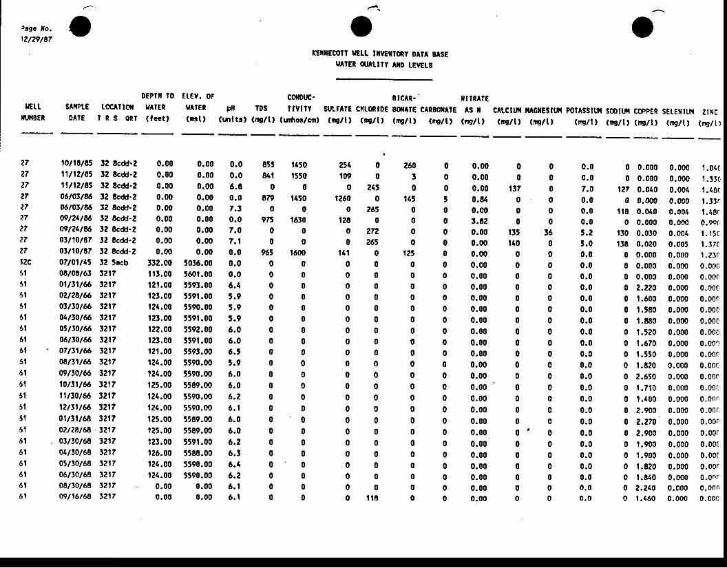
trga fo.t2/29/87
--
sAilPtE toc^ilolD A I E I R S o n l
orEx[Ecolt iGt! tflrclroRy DltA EASE
u lEt otlulY lltD [EvEts
BICAR- ' xtrn^tEsutFAlE cllLoRlDE BOIAI€ cARBoffAl€ AS X CltCttfi lt G[Esttft potAsstu sootut coppER sEtE[ttf{ lmc(ns/tl (nE/t, (ttE/t) (ip/lt (rE/t) (rp/t, (ms/t) (ms/t) (irg/t) (rr/t) (ms/t) (mglt I
o
rGttIIIJT4BER
oEP?[ lo E[ev. oF9ATER gATER(fect) (nst)
cofDuc.ptl rDS f lVl?Y
(tnltrt (nu/l) (urfior/cnl
2?2727272727272727t2c3l3 l6t6 l6 l6 l6 l6 l6 l6 l5 t5 l5 l5 l5 l6 l6 l6 t6 l6 l6 l
10lt8l8t 32 8cdd-211112183 32 8cdd-2lll l2lSS 12 8cdd-206103186 12 Ecdd-zO6l0tl86 !2 Scdd-209124186 12 Scdd-Z09l24l$ 12 Scdd-2Orl10l87 32 8cdd-20tll0l87 32 Scdd-?0710114t 12 5acb08t08t6t 321701ttlt6 t21702t28t66 t217otn0t66 321704ttot66 32170Jt30t66 321706tt0t66 l2l?
' 0ftt1t6 321708n1t66 t2t709t30t66 t2l?10t3lt6 tzt?||t30t66 t21?12tt1t6 t2170lt31t8 t21702t28t68 .3217
. 03t30t68 1217o1tl0t68 t21705t30t68 l21l06t30t68 3217o8/tot68 t21709t16t68 3217
0.00 0.000.00 0.000.00 0.000.00 0.000.00 0.000.00 0.000.00 0.000.00 0.000.00 0.00
332.00 5036.00il1.00 560t.00t2r.00 5593.00t?1.00 5591.00126.00 t590.00r?3.00 559t.00122.00 5592.00r23.00 559t.00rzf.00 5593.00124.00 5590.00t24.00 5590.00r25.00 5589.00t24.00 5590.00124.00 5590.00r25.00 5589.00125.00 5589.00121.00 5591.00126.00 5588.00r26.00 5590.00124.00 5590.00
0.00 0.000.00 0.00
0.00 .06 .A0.07.t0 .07.07 .10 .00 .00 .06 .45 . 95 . 95 .96 .06 .06 . t5 . 96 .06 . 06 . 26 . t6.06 .06 .26 .36 .46 .26 . 16 . t
85t t150841 t550
0 0879 t450
o 09E t630
0 00 0
965 16000 00 00 00 00 00 00 00 00 00 00 00 00 00 00 00 00 00 00 00 00 00 0
2r4 0t09 0
0 24J1260 0
0 265t28 0
o 27;2o 265
111 00 00 00 00 00 00 00 00 00 00 00 00 00 00 00 00 00 00 0
. 0 00 00 00 i l 8
0 0.0000 0.000
127 0.0400 0.000
il8 0.0400 0.000
t30 0.030l3t 0.020
0 0.0000 0.0000 0.000o 2.2200 1.6000 t .5800 1.8800 t .5200 r.6700 t .5500 t .8200 2.6500 r . 7 1 00 t .1000 2.9000 2.2700 2.9000 t .9000 t .9000 1 .8200 1 .8400 2.2100 t .460
0.000 , | .04c
0.000 l .3Jc0.004 1.48C0.000 f .3Jr0.004 l .48(0.000 0.9ec0 .001 t . ' t 5c0 .005 t . 3700 .000 1 .2 t00.000 0.0000.000 0.0000.000 0.0000.000 0.0000.000 0.0000.000 0.00c0.000 0.0000.000 0.0000.000 0.0000.000 0.00c0.000 0.0000.000 0.00c0 .000 0 .00 r0.000 0.00c0.000 0.00r0.000 0.00c0.000 0.00r0.000 0.00t0.000 0.00r0.000 0.onr0.000 0.00n0.000 0.000
26030
t1t0000
t250000000000000000000000
0.000.000.000.840.003.E20.000.000.000.000.000.000.000.000.000.000.000.000.000.000.000.000.000.000.000.000.000.000.000.000.00
000000
36000000000000000000000000
0.00 . 07.00 .00 .00 . 0t . 23 . 00 . 00 .00 . 00 .00 .00 .00 .00 .00 .00 . 00 .00 .00 . 00 .00 .00 .00 . 00 . 00 . 00 . 00 .00 . 00 .0
00
137000
t3tt40
000000000000' 0
0000 '000000
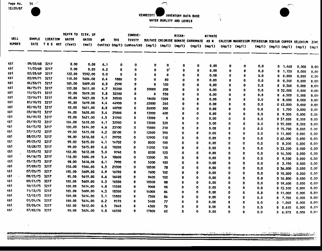
Page lfo.
12t29t8754 '"
osArPtE toclilolD A I E I R S O R I
rEilrEcorfl txvErfloRy DA1A o^sE9A!ER Ar^[trt Axo LEvt[s
v
tttRArEAS I C tcttil fi GXCSttil po?Assttil Sootut coppEt sEtEiltuf{ ztilc
(tns/t) (nc/t! (nS/t) (mg/tl (np/t, (ng/U (nrE/t) (rp/l
tGttNNBER
DEPfil tO EIEV. OigATER YAICR( fcat) (mt )
coflDuc.pll IDS llvnt
(tnltt) (mc/tl (urfios/cnl
8tcAR.slrtF^tE ciltoRtoE toilAtE clREof tc(Ds/ll (ng/t) (ms/tt (ng/t)
16t16t16l16l16l16l(6t
16l(61(61(61
<61(6t(6.|(61
K6l(6t(6t(61(61(61
16l(61(61(61(61(6,|
16lx6lr6lx6t
.wtt0t68 tzr?1ltt0t68 t2l702t28t69 t217ott09t7l 3217o4t30t7l t21706tltt7l t?r?rvtztTr 3?t7l2t14t7l t2t70ltl9t72 321702t10t72 3217ott10t72 321704t19t72 321705t19t72 t2l706t15t72 t2t707n1t72 t2l708t31t72 t21?09t2tt72 t2t710t28t72 t21712t05t72 321704n6tTt 32170stl'tTt t2l707twtT3 321?07t20tn 32r?08t2tt73 t2l709t21t73 tzl?ron7t73 l2t71lt13t7t t2l712t12t|t 121?01t21t74 t21703t26t74 321?07t02t76 t2l7
0.00 0.000.00 0.00
r22.00 5592.00ilo.00 5604.0010t.00 J609.00103.00 56fl.0095.00 56t9.009t.00 562t.0095.00 5619.009t.00 562t.0094.00 5620.0091.00 562t .oO
104.00 5610.00t00.00 5614.0099.00 5615.0098.00 5616.0099.00 5615.0099.00 5615.00
r02.00 5612.00fi0.00 5604.0098.00 t6t6.00
t50.00 5564.00105.00 560{r.0095.00 5619.00
105.00 5609.00r00.00 5614.00t05.00 5609.00r00.00 5614.00100.00 56t4.00r0?.00 56t2.0090.00 5624.00
6 . t 06 .2 00 .0 06.4 t8806.0 25904.7 352005.t 32200t.9 305004.4 a49006.0 407005.4 258004.5 1t9004.1 329004.6 231004.2 28t004.1 297004.1 117004.6 t82005.0 97405.4 t86006.t 7?904.5 213004.9 t67004.6 t64004.1 t63004.8 t55004.3 t83005.1 t58006.2 9t706.5 76404.8 16500
000o '0 00 8 00 120
30000 2000 550
18400 |l0022000 260?6000 300t3000 400ll000 013000 32015000 210t2000 39012900 fiz8000 100
It200 fio8200 tzt
t3000 335000 t00
f0500 787600 t029400 t02
10500 88m00 98
f4000 a7300 865600 774300 70
17800 6!
0 1 .4600 t . r 5 00 0.0000 0.?400 0.3600 12.0000 6.5000 8.0000 43.0000 t .7200 9.3000 37.0000 55.0000 . |5.700
0 11 .0000 62.0000 8.?000 33.2000 14.3000 9.5000 2 .1900 36.0000 10.0000 t0.8000 19.6000 t3 . t000 t t .0000 7.7000 t .0600 0 .6100 6.070
0.000 0.00{0.000 0.0010.000 0.00{0.000 0.0010.000 0.00r0.000 0.00r0.000 0.00r0.000 0.00r0.000 0.00 '0.000 0.00r0.000 0.00,0.000 0.0010.000 0.00r0.000 0.00(0.000 0.00(0.000 0.00(0.000 0.00(0.000 0.00r0.000 0.00(0.000 0.00(0.000 0.00r0.000 0.00r0.000 0.00r0.000 0.00(0.000 0.00(0.000 0.00r0.000 0.00(0 .000 0 .00 (0.000 0.00(0.000 0.Onr0 .000 0 .00 '
00000000000000000000
. 00000000000
0.000.000.000.000.000.000.000.000.000.000.000.000.000.000.000.000.000.000.000.000.000.000.000.000.000.000.000.000.000.000.00
0 . 00 .00 .00 . 00 .00 .00 .00 .00 .00 .00 .00 . 00 . 00 . 0 '0 . 00 . 00 . 00 .00 .00 . 00 . 00 .00 .00 .00 .00 .00 . 00 . 00 . 00 . 00 . 0
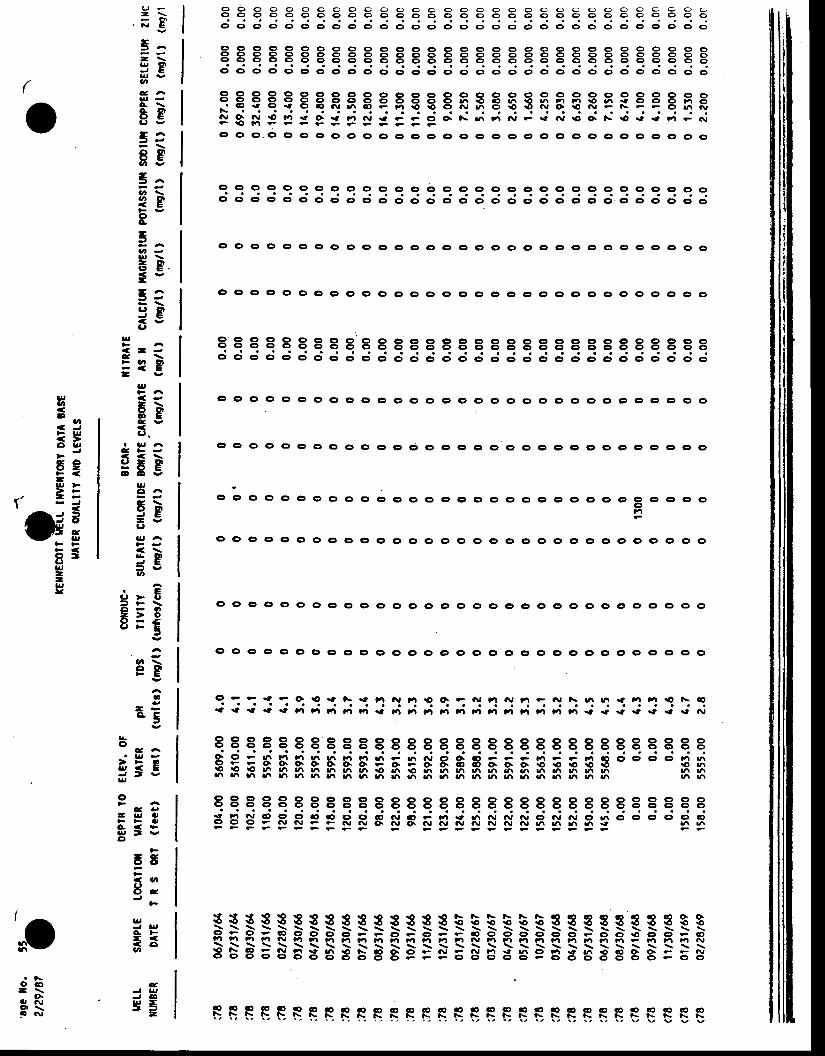
c ) o o o o o e o o e o o o c o o c o o c ) o o o o o o o a o o ao o o o o e o o o o o o o o o o o o c | o o C ) o c ) o e o o o c ) oo o o o o o o o e o o o C , o o o c ) C ) o o o o o o o o o c ) o o o
I I I I I O O O e C ' C ) O c ) C ) O O C r C ' O O O O O O O O O O C r O c )9 9 9 Q | 9 9 O O O O O O C ) c ' O O O O O O O O O O O O e O O O 6c t o o c r o o o o o o 6 6 6 6 6 C ' e C ) o o o o o o o o o o o o o
o c t o o o e o o o c r c r o o o o o o o o o o o o o o o o o o o o
t t t t88r8t r r r r8833B333ss333rr838-. € € e rt Gt € a\J 6 aO F t.l rO € C, .\, Itr O rO € .\i O € (\J - f\ F F O h irF
.\l q ry 9 Fl .t o. { '.| .\, rt ? ? c| O. t\ rn tr t\, ? ra n, rO o. F tO ra rt rA F (\iF € F r - ? - r e r r i
ct o ct e o o o cr o o o cr o cr c) c, C) cr cr o o (! cr o o cr o o cr o o
a -- \. ;g5:- \s8oC A
tg3=8g
5=tgR3
EE.< v-5:9B6 -
a!
< , - -e \> a ^ l l- < E- v
lt
- \8ge v
C ' .
< < \sEgE E V
lr,o AE \
9P- vC'
< \5 0 1J E= vat
3-E= t s \C l - . '- > o8 = f
5
ego
! -a5
(
o9 9 O 9 O o o (t o cr o o ct c' o cr o o (t o o o cr o o o cr cr o o oo o ct o o cr c! c) o c, o cr ct o o c| e o o o o cr o cr o.9 ct o o o cr
Et t888r88888888t88t88888888888ro o o o o o o c , o o o d o d o d o o o c i o c t o o o o o o o c t o
o o C, (t o g o o Ct o o o o (o o o O o o Gr o Ct Cr o Ct o c o o o o
c, o o o o o o 0 0 0 c, cr o o cr o o ct ct cr c, o o o o o o o o o o
o o ct: o o o o o 0 o o o o o o o o cr o o cr o cr e, o o c) o o c'
ct o e o cr o o o o o o Gl G) G) o c, o ct o o o o e Gt cr cr o er er ct ct
o t o ct g o c o o o o o cr .' cr o e, o cr o c) Gr o c) o o o o cr o o€t
0 0 0 0 0 0 0 c, cr o o cr o o o o o o o o c, o o cto o o o o o n
c, c) o o o o cr o o o o o cr o o o o cD o o o o c) cr o o o cr o (t o
ct ct e o o o o c, ct o cr o cr o C) o cr o o o ct c, o o o c, o o cr o c
a!U'
. t Do
a a JF ll,
cl L,J
6eF <-u >> F
7 ' = =
G3F F
o tC'gJt-l!!
q - - rt F o € ia t\ rt f.t ^| ''| ro o. I Gt Ft it tt ? Gr t\ rf| at! rt tt '| ro a\ ct{ { it € rt lA Ft Ft Fl tA rt F| F| fa il 't F| tA rr Ft tl Ft tl rt { rt rt .t rt .t f\l
888888t t888t t t t888t88t8 t t8Br8t rd d J ci ri ?i ei,!i ; ;.'i J
"i d d d ro' J i i ri J : ; d d c; G; c; ;
"iE E 6 A B h B B B8 5 g 5 S S n 3 g h S I3 3 I3 n nh h h n h h ati at! 6 |tr g\ Itt |tr |tr a/l ttt ttt tn art ttr ttr |'t 6 an rfr ta |/r
t888t t8 t88t t t tg t888B8t t t t8 t t t t8EBg9RRPpRRgsgEnFrc$Ns3f i f r 33oo o o3nF F C ? F F F F E F F ? ?
Eo
C A
z= 2= t sU
0a a Y
- s J O
a < >a r r t vC'
g5<' vtt n
ar,A F- << aU'
4
J @f r E- - -
o c o- \G
ar .\J
a t !
$$$ss333 8338838b555bi3333333 3S$BigF-Fg-g-HB-r -E- iE-g- i ; -R-g-g-B-g-g-g- ; -B-B-p-g-g- ; -F-> . ^ \ : , \ : \ f \ \ \ \ \ \ \ \ \ \ \ \ \ \ \ \ \ \ \ \ \ \ \ \ \ \
3535383885899=rEgBSEeBtBt tB g=Eg.rf-
EEEEEEEEBsEEETTEEESEEESEESE€€EE
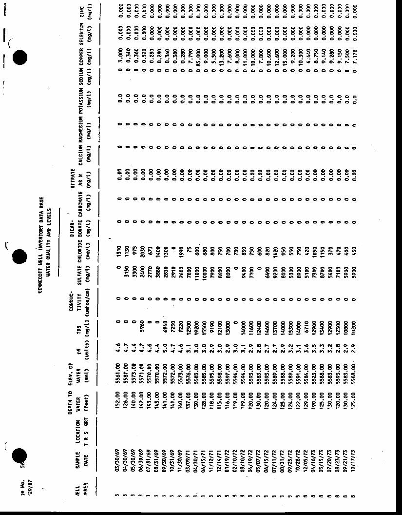
9 9 o o o O o o o o o O o o o o o o c ) O o o o O o o O q e c o9 9 9 o o o e o o o o o o o O o o o C ) O o o o o o O 9 o o c oe 9 0 0 0 0 0 0 0 0 0 0 c ) o o C ) C ' o c | e o c ' o o o o o o o o oo o c t o t S 0 0 0 0 0 0 0 0 0 0 0 0 c ' 0 0 0 0 0 0 0 0 0 0 0 ( > o
Q I I 9 O o O O O O O O ct ct O o O ct ct O O O O ct Ct O O O O O c'at t t t t8 t t t t8 t t8888888 t tB8 t t t883ct o o o o c) o o ct o c, o o c, o cr o c, o o o cr o ct o cr o o o o o
I e I 9 e o ct o cr o cr cr c) cr c, o o o c, o o cr o o o cr c) o o o 6!i !! fq N <, G, tO C, <, O. O O O g O O O ct o O O o O ct € 6 € Gt h o Le F n h hr a\r Fl Ft .\, t\ o o arr .\t .o o o cr ct <l ro e .\, Ft € f\ F |\t F 6 -m C> O O O Ct O Cr c) a\ t'| Or 6 rA t\ aO F C' 0\ O .\, |'r O. O rt O O. Or O\ |\ N
o ?ct o c, o ct o cr o (t cr o cr o o o o o o cr o ct ct o cr o cr cr o o cr o
o 0 c, o cr o o c, c) oo o I o o o c c, o rt o o o ct o o o o o c o
o o o o ct o o (t o o o o 0 0 0 0 C' G' o o c, o o cr cr o c, c, cr o o
c, o at cr o o ct o o ct o o cr c, c, o cr o o o o o I cr o o o ct o o o
o o Gt o o G, ct o o o o o ct o o cr G' e, cr 0 0 cr 0 Gr o ct Gr e o tD 0
q I 9 O O C' rO C' Ct o c) o o o o o o o o cr o cr o c) o o o o o o ec, o o c oo o o o et cr cr c) o o o o o o o o o (f o cr o o o o o d
t8888 t8 t88 t tEB8gBtB I 8888S888888o o o o o o o c , o o o o o o o o o o c ) e o o o o o c r o o o o o
0 o o Q o o o o G) G) G) Gr G' Cr C' G, cr c) c) c) c) O O 0 c' O Cr c) cr O Gt: 9 ! t r t r n , O g C t O . C t C , O O C ) O O C ) O O F O O O O C T OI q l v N r t r f \ r . t r ? F C t O r O r r € F C ' F t C ) l s O r t O . F l ( r ^ Jn € F f \ g 9 F o I B : = E : = : F : . o S 3 S g 9 9
9 \ .t 0\.O { o t\ rO e Ct O o| C) O. C' F Or G t\ t\ O N ; € a'| '| r\r 6 O o.ia ra rt { { € 6 { r' Ft ''t ''| N |'t 6r tt r.t G| N n, (\r N ra rt |.| |,i tt Fr N G, f\l
EFFFEgEeERSEEFFFEF€E gFfi ESEESEeE' 888Ft8e8888888088ot888888 t8888
;NXF*FEFFPEFSE 8= TFBFg;FEI -gF
t88 t88888883S8888888888889r 88r rd lj ri ; d d r{ rJ ; d J,,i yi d lj j= :-J !: r: F F F ts ts ts e.o o. o. o. o t B ts B S I $ e t F I B I ts 3!4 !4 !r_r !{r vt ul yr rn t'i 6 rft ur ur |'t rn |/! ur |,r ari atr |'r a'r |/r ari tfr rtt ati an h a^ ur6 h h h l/\ 6 ati |'t an |'r |fr |'r yi 6 tn |'r gr .,t t't |tr att ati atr yr a/r 6 ui rtt yr .'t 6
888t88t8888888888888rr r888S8888!! 9 I a! rr tl ? ? Ct ls O aO O ur !O Or O O O O rt Ur rt f\t O. O ./i O C, O hh a Y Y rt rt it tt rt Fl Ft .\, F F F F - .\J tl a\, a\t .\t nJ a\, .\, o .\, t'| n rrl N
G F F F F F F F F F F F F F F G F G E ? E ? F F F F G ?
o o ct o c) o o o o o o at o c, c, o o c> o o o o o o o cr o o o o o
$3$$SS$$8 f , EF=FNNNNSNNSSNSRRRRt rFg- i g- g- -- -- o- -- o- o.- o- -- *- o- o.- o- o- 6- r-- -- -- ) ^- e- -- .o- -- o- -- -- *-f. !-r fr fim Fl Fl ttl f4 c) Ft F C, e - ',| it .\r Ct F ? .\r ^, .\rc
BB83E88e=838=g5gB3 gES gges tES 8Be
6 6 6 - - - - - a - 6 6 6 6 6 6 6 6 6 6 a 6 6 O 6 O 6 € 6 l t t c f t
= \;E
5=- \3go
Eg- A= -8E
3^
?goA
5
Eg-- A= r
9gC'
tl,
< . - -e \> u r d r- < E- v
lg
- \g gC YC'
. C < \c r - o l- O Ea D & Y
ua Ag \
o g )- v(,
B g t- t EU'
6-E' F \c ) - ' |- > o8=€
5
ego
! -o . 5
|r,v,.D
t6. C J
ct lr,
6eF <-u, '.Z a
=eS-
g
a tu,--ltv
to
Il(
G A
3s&o
g
g
o
etrjCI
e . ua! l,r ( 5l v
- eC ' O
<, g,(,O c
|r,E F- << aU'
eJ 6t g =
3ess
a
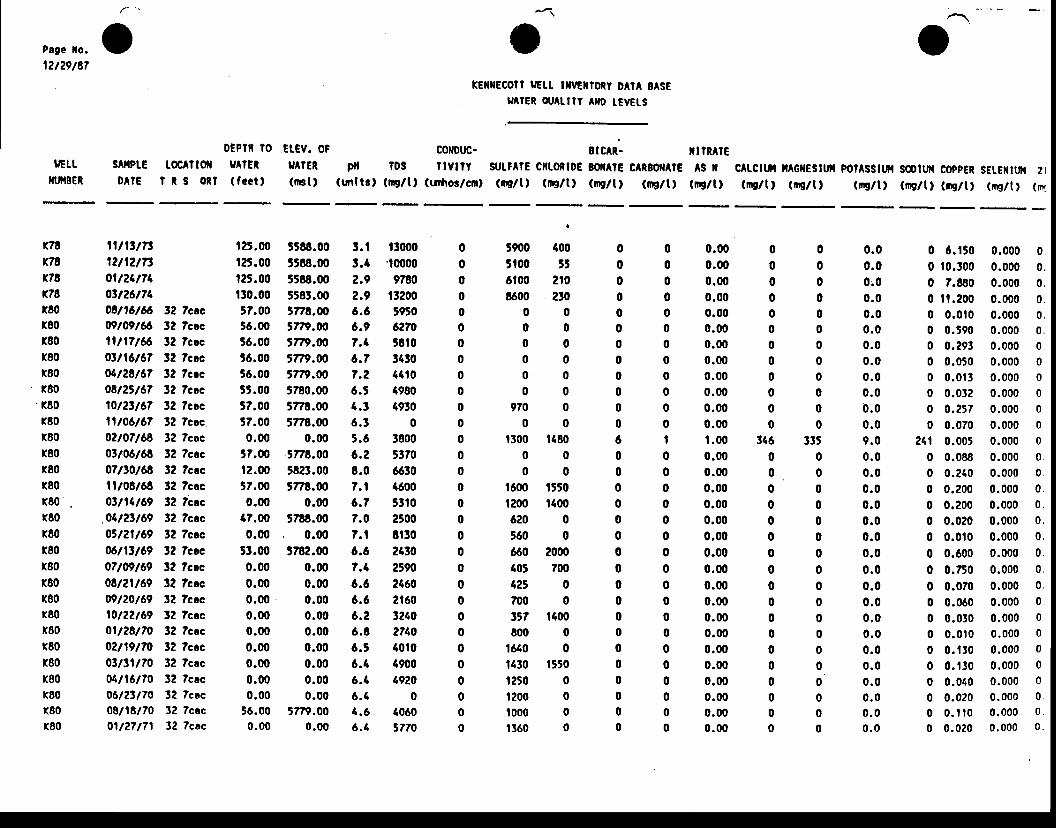
v otEil[ECOI? UELL mrclroRy 0AlA BASE
gAIER otAulY AXo tEvEts
c0[0uc- 8tclR. xllRArEptl tos llvtlY SULFAIE CilLoRtDE sonrE CARBO|AIE AS tl
(mltr, (rallt (urfior/crnt (nsltl (mE/tt (ng/l) (rng/tl (rng/t)
o
c^tctuil i^GxEstw pot^sstur sotw coppEn sEtEutt| 2r(qt/t, (qt/lt (rig/t) (ms/l) (nglt, (mglt) (nr
IGLTXUIBER
DEPlft lo Et-Ev. 0Fs^ltP[€ toc ltoft 9A!ER rJ tERD A I E I R S o n l ( f c c t , ( n s t l
t900 400 05100 55 06100 210 0t600 230 0
0 0 00 0 00 0 00 0 00 0 00 0 0
9 7 0 0 00 0 0
1300 t180 60 0 00 0 0
1600 t550 01200 t100 06 2 0 0 05 6 0 0 0660 2000 0{05 700 04 2 t 0 07 0 0 0 0ttt t100 08 0 0 0 0
1610 0 0t430 t550 01250 0 0t200 0 0t000 0 0| 1 6 0 0 0
x78x78r78x78r80r80180r80r80
' r80180x80x80r80180180r80x80r80r80x80(80x80x80r80x80r80x80x80r80r80
l l t l ttTt12t12t7301t24t74ott26t740El16l6 t2 ?ccc@109166 12 Tcacll l lT166 t2 Tcac0t116167 32 lccc04128167 12 Tccc08125167 32 Tcacl0l2tl67 32 Tccc11106167 32 Tcac0210716o 32 Tcoc0tl06l66 32 Tcac071t0168 32 Tcacll/08/68 t2 Tcac0tll4l69 32 Tcac
.04123169 32 Tcac03121169 32 Tcec06111169 !2 Tccc07109169 32 Tccc0El2ll69 t2 ?csc09120169 t2 Tcac10122169 12 Tccc0ll28l70 32 Tcac02119170 32 Tccc0tlt1l70 32 Tccc04116170 32 Tcac06121170 32 Tcac08118170 32 Tccc01127171 3? Tcac
r25.00 5588.00125.00 5588.00t25.00 5588.00[0.00 5583.00,7.00 tn8.0056.00 t7t9.0056.00 t7t9.0056.00 5279.0056.00 t7m.0055.00 5780.0057.00 528.0057.00 5778.000.00 0.00
57.00 528.00t2.00 5823.0057.00 528.000.00 0.00
{7.00 5ru.000.00 0.00
53.00 5782.000.00 0.000.00 0.000.00 0.000.00 0.000.00 0.000.00 0.000.00 0.000.00 0.000.00 0.00
56.00 5779.000.00 0.00
3.t 130003.4 -t0000
2.9 97802.9 132006.6 59506.9 62m?.4 58t06.7 34307.2 44106.5 49804.t 49106.3 05.6 38006.2 53708.0 66307.1 46006,7 53t07.0 25007.1 Er306.6 24307.1 25906.6 21606.6 2t606.2 32106.8 27406.t 40106.{ 49006,4 49206.4 01.6 40606.4 5770
0.000.000.000.000.000.000.000.000.000.000.000.001 .000.000.000.000.000.000.000.000.000.000.000.000.000.000.000.000.000.000.00
000000000000
346000000000000000000
000000000000
3r5000000000000000000
0.00 .00 ; 00 .00 .00 . 00 .00 .00 .00 .00 .00 .09 . 00 . 00 . 00 .00.00 .00 .00 .00 . 00 .00 .00 .00 . 00 .00 . 00 . 00 . 00 . 00 . 0
0 6.150 0.000 00 10.300 0.000 00 7.880 0.000 0.0 11.200 0.000 00 0 .0 t0 0 .000 0 .0 0.590 0.000 0.0 0.291 0.000 00 0.050 0.000 00 0.013 0.000 00 0.032 0.000 00 0.257 0.000 00 0.070 0.000 0
211 0.005 0.000 00 0.088 0.000 00 0 .?10 0 .000 0 ,0 0.200 0.000 0,0 0.200 0.000 0,0 0.020 0.000 0.0 0.010 0.000 0.
0 0.600 0.000 0.
0 0.750 0.000 0,
0 0.070 0.000 0.0 0.060 0.000 0,0 0.010 0.000 00 0.010 0.000 00 0.130 0.000 00 0 .1 !0 0 .000 00 0.010 0.000 00 0.020 0.000 00 0 . 1 1 0 0 . 0 0 0 0 .0 0 .020 0 .000 0 .
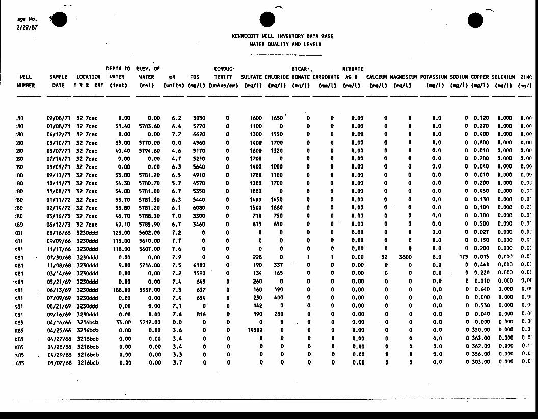
tgc tfo.
2t29t87
tGU.luil8ER
ooEPl[ to ctEv. oF
sA[PtE t oc^ilor u rER u^rEto l l E I R S o R f ( f e c t l ( m r t )
--'
(EllEcotr 9Et[ txvcrftoRt oAtA SASEultER otAUIY AilD [EvEt-s
corDuc- 0 lcAR. . ulRAtEpfl IDS tlvllY suttltE Cllt0RlDE lOxAtE CAREolAl€ As ll
(mltrl (tng/t, (Ldror/crn, (nrglt) (mg/t) (ip/t ' (q/t) (ru/ltc tctm mcflEsltit po?^ssltil soltI CoPPER sEr.Extuil 2txc(ne/tl (mc/tt (mE/t) (ms/t) (mslt, (iE/t) (ris/l
5030 0 t600 1650 05 n 0 0 r 0 0 0 06620 0 1300 1550 04560 0 t400 1700 05170 0 1600 1320 05 2 t 0 0 1 7 0 0 0 05610 0 1400 1000 049t0 0 1700 il00 04170 0 1300 1700 05 1 5 0 0 1 8 0 0 0 03440 0 t(00 1450 06080 0 1500 1660 03300 0 710 750 03160 0 615 650 0
0 0 0 0 00 0 0 0 00 0 0 0 00 0 2 2 8 0 t
6t80 0 190 337 0t590 0 131 t65 06 4 5 0 2 6 0 0 0617 0 t60 190 0656 0 230 400 0
0 0 1 4 2 0 08t6 0 190 280 0
0 0 0 0 00 0 1 4 5 0 0 0 00 0 0 0 00 0 0 0 00 0 0 0 00 0 0 0 0
:80:80:80:80:80:80:80:80:80:80.80i80(80(80(81(81(81(81(8t(81
-(81(81(8t(81(8t(8t(85r85r85r85k85
0210E171 32 Tcac03108171 32 Tcac041121?1 32 Tccc0Jl10l7l 32 7cac.06107171 12 TcccO?l14l7l 12 Tcec08109171 32 TcacWl13l71 t2 Tcec10l1ll7l 32 Tccc11108171 32 Tcac0ll1ll72 32 Tcac02114172 32 Tcac05l16lTt 32 7mc06l12lTt 32 Tcac08tl6t66 3230ddd09t09tc6 3230ddd11t17t66 l230ddd07ttot68 3230ddd1lt08t6tr 32l0ddd01t14t69 3230ddd0il21t69 3230ddd06t'ltt69 3230ddd07t09t69 32!0dddo8t2lt69 3230ddd09t16t69 l230ddd01l16166 32t6bcb04125166 32l6bcbO1l2716 32t6bcb04128166 32t6bcb01129166 32l6bcbOrl02l66 32l6bcb
0.00 0.0051.10 5783.600.00 0.00
65.00 5770.0040.40 5794.600.00 0.000.00 0.00
53.80 578t.2054.30 5780.7054.00 578t.0051.70 578t.1051.E0 578r.2016.70 5788.3019.t0 5785.90
123.00 5602.00i l5.00 5610.00il8.00 5607.00
0.00 0.009.00 5716.000.00 0.000.00 0.00
r88.00 5537.000.00 0.000.00 0.000.00 0.00
31.00 52r2.000.00 0.000.00 0.000.00 0.000.00 0.000.00 0.00
6.26 .47.20 .04 .64 . 76 .16 . t, . 76 .76 .36 . 17 .06 . 77 .27 . 77.67 . i7.57 .27 .17 . t7 .47 . 17.60 . 03 .63 . 43 . 43 .33 . 7
0.000.000.000.000.000.000.000.000.000.000.000.000.000.000.000.000.000.000.000.000.000.000.000.000.000.000.000.000.000.000.00
0.00 .00 .00 .00 . 00 . 00 . 00 .00 .00 .00 . 00 .00 . 00 . 00 .00 .00 . 0E.00 . 00 . 00 . 00 .00 .00 .00 . 00 .00 .00 . 00 . 00 . 00 . 0
0 00 00 00 00 00 00 00 00 00 00 00 00 00 00 00 00 0
52 38000 00 00 00 00 00 00 00 00 00 00 00 00 0
0 0.120 0.000 0.000 0.270 0.000 0.000 0.400 0.000 0.000 0.800 0.000 0.000 0.010 0.000 0.000 0.200 0.000 0.000 0.010 0.000 0.000 0.010 0.000 0.000 0.200 0.000 0.0c0 0.a50 0.000 0.0r0 0 .130 0 .000 0 .0 r0 0 .100 0 .000 0 .0 r0 0.300 0.000 0.0c0 0.500 0.000 0.0(0 0.027 0.000 0.0t0 0.150 0.000 0.0r0 0.200 0.000 0.0(
175 0.015 0.000 0.0r0 0.410 0.000 0.0r0 0.220 0.000 0.0t0 0.0. |0 0.000 0.0t0 0.640 0.000 0.0r
0 0.000 0.000 0.0r
0 0.530 0.000 0.0(
0 0.010 0.000 0.0r0 0.000 0.000 0.0(0 350.00 0.000 0.010 363.00 0.000 0.0(0 362.00 0.000 0.0 '0 156.00 0.000 0.0 '0 303.00 0.000 0.0 '
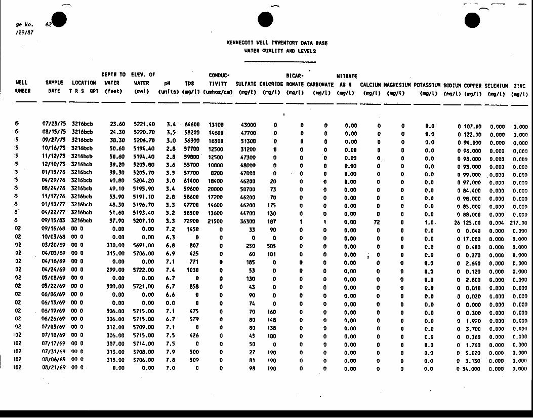
.o orElx€cotl tGLt tlwxtoRy oAtA 'ASE
u tEn ou utY AID tEVEtS
stc^i- TITRAIEpfl lDs tlvlrr slrt?AlE ctltoRlDE oolAlE cARBfiltE AS r CAtCttt{ lt^GrfEsttn pottssttfi sootut coppER sEtEiltw 2txc
(tnltl) (rEltt (tafror/crnl (rns/t) (nc/t) (ng/t, (mg/l) (rE/t, (rrrg/t, (m9l1, (mg/t) (ns/t) (ru/t) (iE/t) (rE/t)
9c fo.
t29/87
rGu.IU{gER
s^rPt EDAIE
DEPTII IO CI.EY. OFtoc^Tto t 9 lEn HIER
I R S oRt (fectt (rBt)
000000000000
72000
; 000000000000000
0 00 00 00 00 00 00 0
2 0 0T t 0m 0
175 0130 0187 I9 0 00 0
505 0tot 0
0 00 00 00 00 00 0
t60 0148 0t38 0lB0 0
0 0t90 0190 0190 0
r5r5r5t5;J
,5;!
r!
i5
i t
' ,5t0202020202020202020z020202t02t02t02t02t02
07lztl7S 12l6bcb0811517, 32t6bcb09127175 32l6bcb10116175 32t6bcb1ll12lI5 Set6bcbl2ll0l75 32l6bcb01ll5l?6 32l6bcb04129176 32l6bcb08124176 32l6bcb1ll l7176 32t6bcbOlllt l7T 32l6bcb04l2un 32t6bcb09lltl&t 32'l6bcb09t16t68 00 010/01/68 00 00tt20t69 00 004t03t69 00 004t16t69 00 004t21t69 00 005t08t69 00 005t22t69 00 006t0d,t69 00 0o6tllt69 00 0o6n9t69 00 006t26t69 oO O07/01t69 00 007t10t69 00 007t17t69 00 007t31t69 00 008t06t69 00 0o8t2tt69 00 0
2t.60 5221.1024.t0 5220.7038.30 5206.m50.60 5t94.4050.60 5194.40t9.20 5205.8019.30 5205.7040.E0 5204.2049.r0 5r95.9053.90 5r9t. t018.10 5196.7051.60 5193.4017.90 5207.t00.00 0.000.00 0.00
330.00 569r.003r5.00 5706.00
0.00 0.00299.00 3722.00
0.00 0.00300.00 5t2r.00
0.00 0.000.00 0.00
306.00 57t5.00106.00 57t5.001,|2.00 5709.00306.00 5715.00!07.00 57t4.001r3.00 5708.003r5.00 5706.00
0.00 0.00
t.4 646003.5 582003.0 563002.E 577002.C t98003.6 557003.5 577001.0 6t400t.{ 596002.8 58600l.l 177001.2 585003.3 729007.2 t1506 .3 06.8 E076.9 42t7.r n11.4 10306 .? 06.7 8586 .6 00 . 0 07.1 1756.7 5V'7 . 1 07.3 1267 .5 07.9 5007.8 5097 .0 0
0 t07.000 t22.000 94.0000 96.0000 98.0000 93.0000 99.0000 97.0000 84.1000 98.0000 85.0000 88.000
26 't25.00
0 0.0100 17.0000 0.1800 0.2700 2.6400 0 .1200 2.E000 0.0t00 0.0200 0.0000 0.3000 t .9200 3.7000 0.3600 t . 7600 5.0200 3 . t 3 00 31.000
0.000 0.0000.000 0.0000.000 0.0000.000 0.0000.000 0.0000.000 0.0000.000 0.0000.000 0.0000.000 0.0000.000 0.0000.000 0.0000.000 0.0000 .004 2 t7 .000.000 0.0000.000 0.0000.000 0.0000.000 0.0000.000 0.0000.000 0.0000.000 0.0000.000 0.0000.000 0.0000.000 0.0000.000 0.0000.000 0.0000.000 0.0000.000 0.0000.000 0.0000.000 0.0000.000 0.0000.000 0.000
t l t0011600t630012500t2500108008200
t810020000t720014600t360021500
000000000000000000
4300047t005t300312004730048000(7000462005070046200462004470036300
330
25060
18553
t30tt9074708080I550278l98
0.000.000.000.000.000.000.000.000.000.000.000.000.000.000.000.000.000.000.000.000.000.000.000.000.000.000.000.000 .000.000.00
0.00 .00 . 00 .00 . 00 .00 . 00 . 00 .00 . 00 . 00 . 0t . 00 . 00 . 00 .00 .00 .00 .00 . 00 .00 . 00 . 00 . 00 . 00 . 00 . 00 . 00 . 00 . 00 . 0
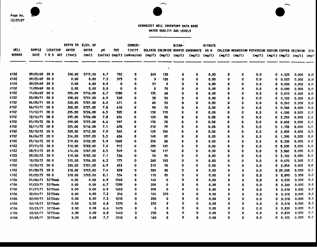
Page llo.
12t29/87
rGttNfiBER
j
sAilPtE t oc^ilolD A I E l t s o R l
DEPflt l0 Et EV. OF9 lER 9 lEn( fect l (nst )
corDuc-pll tDS llvl lt
(tnltt) (n9/t, (uTfiG/cm,
xE[[ECOtt tGt[ llrGiltony 0AlA BASE9 lcn ou^ulY AtfD tEvELs
ilcAR. iltrR^tcslrt?AlE crtoRlDE BoilArE GARBOfATE AS tl(nc/tl (De/t) (ne/lt (ms/t) (Ds/tl
o
cltcttil ltAGxEstur PotAsstut s00ttil coppEt sEtEiltf{ ltN((nc/t) (rp/ t) (ng/t) (w/t) (ms/t l (ng/t) (n9/ l
n02fi02rt02n02n02rl02rl02n02n02n02Kl02rt02ff02(,|02n02n02rt02n02fi02r102xl02(102(,|06( t06(106
r l06xr06K'.|06r l06Kl06r l06
09t0rt69 00 009t2tt69 00 009t29t69 00 011t09t69 00 0llt24t69 00 00tt09t7l 00 004ttot?l 00 006t15t71 00 0lln2tTl 00 012tr4t7l 00 001t19t72 00 0o2n1t72 00 003n0t72 00 004t24t72 00 005t16t72 00 007t11t72 00 008t11t72 00 009t2il72 00 010t28t72 00 012t03t72 00 00lt08t7t 00 00tt20t7t 00 001106171 l2lSbcb01120171 12lSbabOll27l? l !2 l5bab02lo417l 3?t9bab02109171 32l5bab02118171 1213bab02t2tl71 32l5babOltOztTl 32l5bab03lO8l71 3215beb
306.00 5715.00 6.70.00 0.00 ?.t0.00 0.00 0.00.00 0.00 0.0
!o5.oo 57t6.00 6;.??90.00 573t.00 6.9320.00 5701.00 6.2300.00 572t.00 7.t295.00 J7Z6.O0 6.5295.00 5726.00 7.E299.00 5722.00 6.6305.00 57t6.00 7.1309.00 57t2.00 7.9314.00 5707.00 5.t3t9.00 570?.00 5.9318.00 5703.00 7.0il4.00 5707.00 6.5319.00 5702.00 7.1315.00 5706.00 6.3320.00 5701.00 6.93r8.00 5703.00 7.13r8.00 5703.00 E.t
0.00 0.00 6.90.00 0.00 6,70.00 0.00 6.90.00 0.00 7.20.00 0.00 7.t0.00 0.00 6.80.00 0.00 6.60.00 0.00 6.80.00 0.00 7.7
702tt3
00
t5803204?l4t0505634591678563636
10609t l549536775652828534
15601390t640346
t2 t0t37011701610r5 l0
0000000000000000000000000000
. 0
00
0.000.000.000.000.000.000.000.000.000.000.000.000.000.000.000.000.000.000.000.000.000.000.000.000.000.000.000.000.000.000.00
0 . 00 .00 .00 . 00 . 00 .00 . 00 . 00 .00 .00 .00 .00 . 00 . 00 . 00 . 00 . 00 .00 . 00 . 00 .00 . 00 .00 . 00 . 00 .00 . 00 . 00 . 00 . 00 . 0
240 tto0 . t 2 0
5 t 00 7 0
t35 68l8 5060 5090 70
130 flot20 90t30 702t0 tI)t20 t00t40 92150 88280 105160 il750 95
260 t003r0 90380 80ilo 85140 0?00 0290 0r24 370200 0230 0
0 0230 0t60 0
0 1.2200 0.0200 0.0000 0.0000 0 .0100 0 . t200 0.2400 0.3600 4.3000 3.2000 0.6000 t . t 5 00 2.0t00 1.1900 8.3000 t .5000 3.c600 1 . t600 0.4700 2.8500.29 .0000 4.c900 0 .0 t00 0.2600 0 .0100 0 . 0 r 00 0 .0 t00 0 .0100 0.8390 0.8390 0 . 1 2 0
0.000 0.0{0.000 0.010.000 0.0r0 .000 0 .010.000 0.0 '0.000 0.0,0.000 0.0,0.000 0.0 '0.000 0.00.000 0.00.000 0.0,0 .000 0 r00.000 0.0 '0.000 0.00 .000 0 .00.000 0.0r0 .000 0 .0 '0.000 0.010.000 0.010 .000 0 .00 .000 0 .00 .000 0 .00 .000 0 .00 .000 0 .00 .000 0 .00 .000 0 .00.000 0.00 .000 0 .00 .000 0 .00 .000 0 .00 .000 0 .0
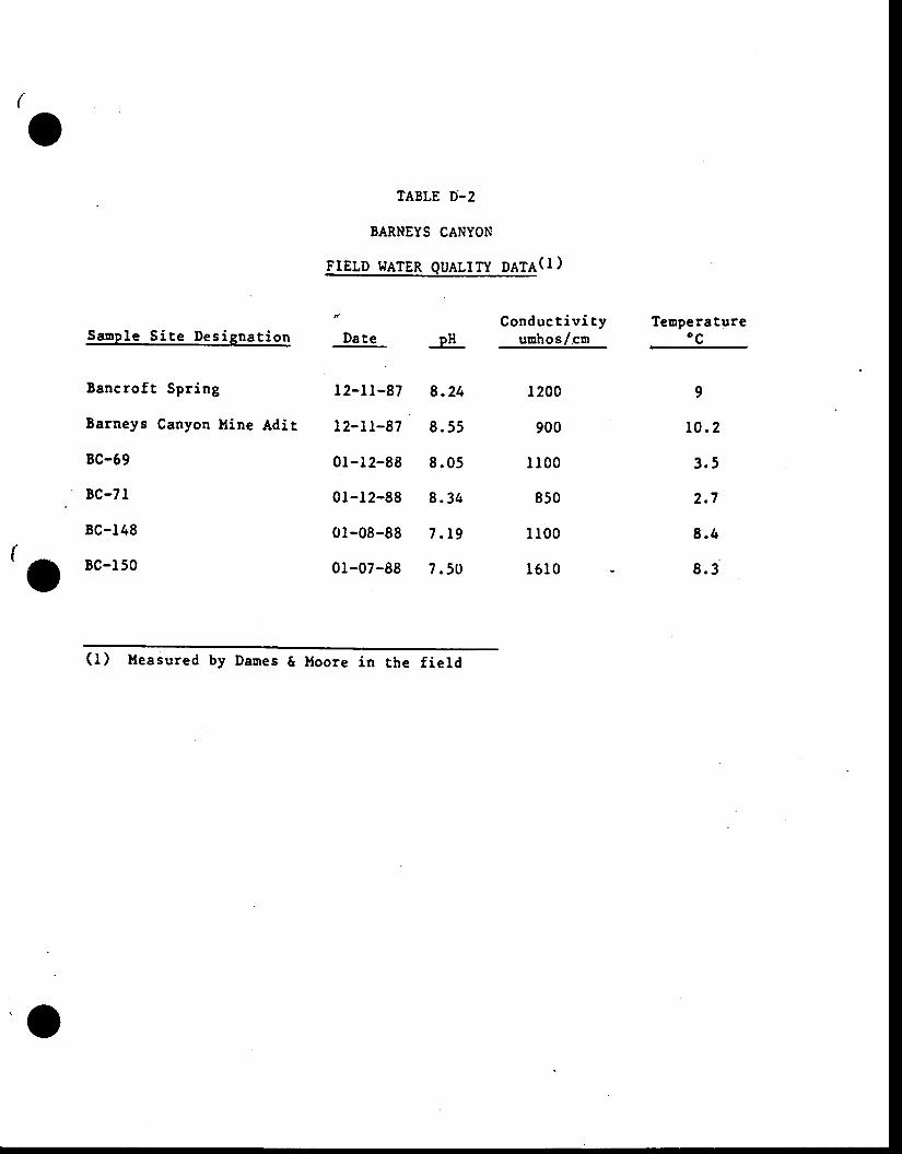
TABLE D-2
BARNEYS CANYON
FIELp l.rATER QUALTTY pATA(l)
,o
S a n p l e S i t e D e s i g n a t i o n
Bancro f t Spr ing
Barneys Canyon Mine Adit
BC-69
BC-71
BC-148
BC-l 50
Date
I 2- l l -87
I 2-l r-87
01-12-88
0l -12-88
0l-08-88
0l -07-88
Conduct iv i t yuuhos/cn
1200
900
I 100
850
I100
161 0
Tenperature,oc
9
10 .2
3 .5
2 .7
8 .4
8 .3
OH
8 .24
8 .55
8 .05
8 .34
7 . t 9
7 .50
( f ) l leasured by Daures & Moore in the f ie ld
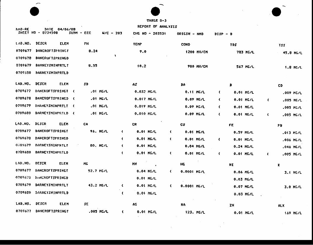
v
hnD".RESHEET
l . r i [ r . N0.
0709677
0?096?8
0709679
07096S0
LA8 . NO.
o?oj677
0?096?8
07a9679
0?09680
LAt r . N0 .
0709677
07g967B
o'iotI,79
0?b9600
I A I r . NO.
07096?7
07096i 'u
0?096?9
0709680
DAtE Oa/O6/OgN0 - 0734509 SUttH -
DESCR ELEI,I
BANCROFTST.RT NCT
BANCRUT'TSPR I NG D
BARNEYSTI I NPRTL T
SARNEYS}I I NPRTL D
DESCR Et.Etl
EEC
FH
8 . ? 4
0 . 5 5
u/c - 203
COND
| 200 lilt/cll
900 liltlcll
EA
0. | | i lGlL
0.09 l t6lL
0.09 l tc l l
0.09 l tc l l
CU
0.ot ] tGlL
0.ot i r6lL
o.oa l tc lL
o.ol i tc lL
l{c
0.000t i lc lL
0 .000t l tG/L
D I S P - D
(
(
(
(
TDS
?et n6/L
J67 NG/L
0.0 t l t c lL
o .0 l l t c lL
0 . 0 1 H G I L
o . 0 t H 6 l L
0.59 l tc lL
o.0t l tc lL
o .21 nGlL
0.0f l tc lL
0.06 l , tc lL
0.03 t tc lL
0.0? l tc lL
0.03 l,tclL
TSS
4 5 . 9 H G I L
1 . 8 i t c l L
.00? rc lL
.005 HGIL
.005 l {G/L
.oo5 rG lL
.01 3 l tc lL
.006 l tc lL
.046 hc lL
.oo5 nG/L
3. I l,rclL
3.0 l , rc lL
s8 CD
TTANCROFTSF.RING T
EANCROFTSPft INGD
II' iRNgYS}tI NPRTLT
SAnNEYSl,n Nr,riTr-D
DESCR ELEh
gANCROFTSPRINGT
t 'ANCROFTSFRINGD
TARNEY.IH I NF.RTLT
EARNEYSIII NPT{TLD
DE.SCR ELEII
TIANCROFTSPRI NGT
Lt l f lCR0Ff SPRINGD
BARNEYSI{I NF.RILT
t'AKilEYSll INFRTLI)
.o t nG/L
.01 l t6lL
.0 t HGlL
.01 lrc lL
96. nG/L
00. HGIL
52.7 t1G/L
43. ? ] tGlL
(
(
(
(
PEFECA
(
(
(
(
NTltG
(
(
LA8.NO. DESCR ELEII
0709677 IIANCROFTSPRIN6T
oTABLE D-3
REPORT OF ANALYSIS
cl rc No : 10353t ORtGtN - NHD
TETIF
9 . 0
t o . t
AS
0.03? r,rG./L
0.0 | 7 l tc lL
o .o t I i l c l L
o .0 lo l , t c l L
CR
o.ot l tc lL
o.0t l tG. /L
o .o t i l 6 l L
0.ot i rc lL
llN .
o .04 HGIL
o .0 t HGIL
0 .0 t l r c l L
0.0t l , tc lL
A6
0.ot l t6 lL
SE
.005 lt6lL
NA
| 23. ltclL
ZN
0.0 t HGIL
ALK
169 nG/L
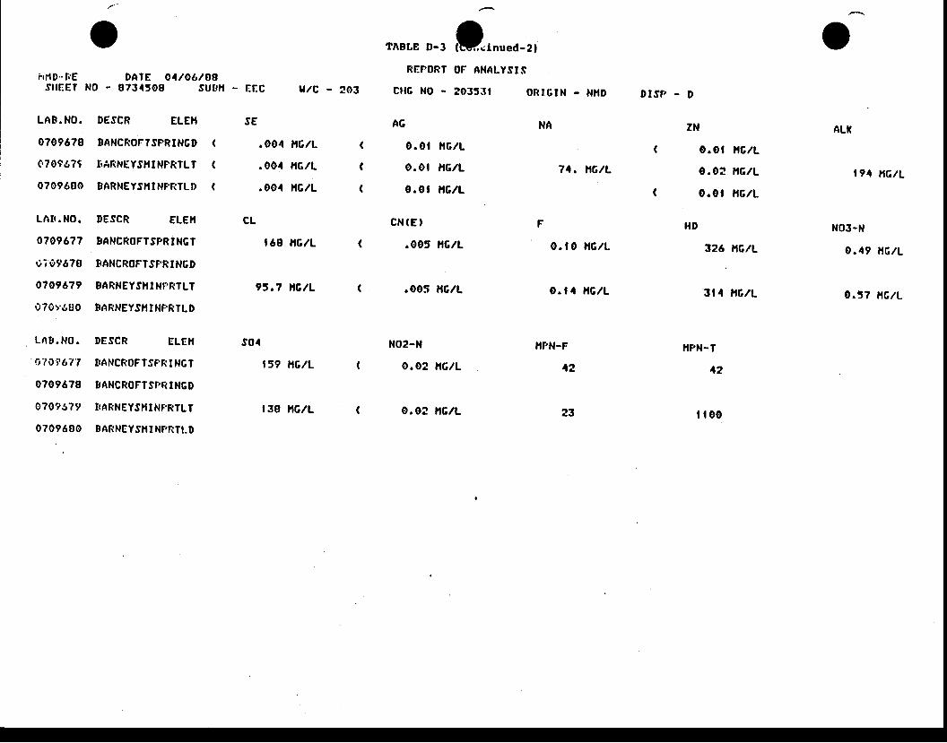
hrtD- IrEsilEgt
LAB.NO.
07096?0
e?0eg?t
0?09680
LATI . NO.
o?0967?
t)? 0t6?B
0?096?9
070r.s00
L A B . N O .
o7 ir'it 67'l
0?09678
0709!r79
0709680
^
v
DATE O4/06/88N0 - 0?3450S Sutr l l
DESCR ELEII
EANCROTTSPRINGD
T.ARNEYS}I T NPRTLT
9ARNEYSIII NFTTTLI)
DESCR ELEh
EANCROFTSPRTNGT
BANCROFTSPRINGD
SARNEYS}I I NT.RTLI
BARNEY.S}I tNI'RTLD
DESCR ELEII
TTANCROFTSPR I NGT
BANCROFI SPI I NGI)
TTARNEYSHI NF.RTLT
BARNEYS}II NPTITLD
(
(
(
- EIC
SE
.004 l tc lL
.004 ttc./L
.004 HGIL
CL
| 68 lt6lL
?J .7 NG/L
s04
159 nc/L
| 38 itcll
u/c - ?o3
(
(
(
I^BLE o-t rilnued-2tREPORT OF ANALYSI. f
c l rc No - ?035.r t o f t tc tN - Ni tD
74, nG/L
0 . |0 i lG lL
o. | 4 ir6ll
DISF, - D
ZN
o.0t l tc l l
o.02 i f6l l
o .0 l HGIL
HI'
326 nc/L
3t 4 ltclL
}IPN-T
42
i l00
oAG
o.ot l tclL
o.ot l,tclL
0.0t l t6lL
C N ( E '
.005 ltclL
.005 ftclL
NO?-N
0.02 l,tclL
o. 02 il6lL
NA ALI(
194 nc /L
NO3-N
0 .49 i lG /L
o.37 Ac/L
}IPN-F
12
23
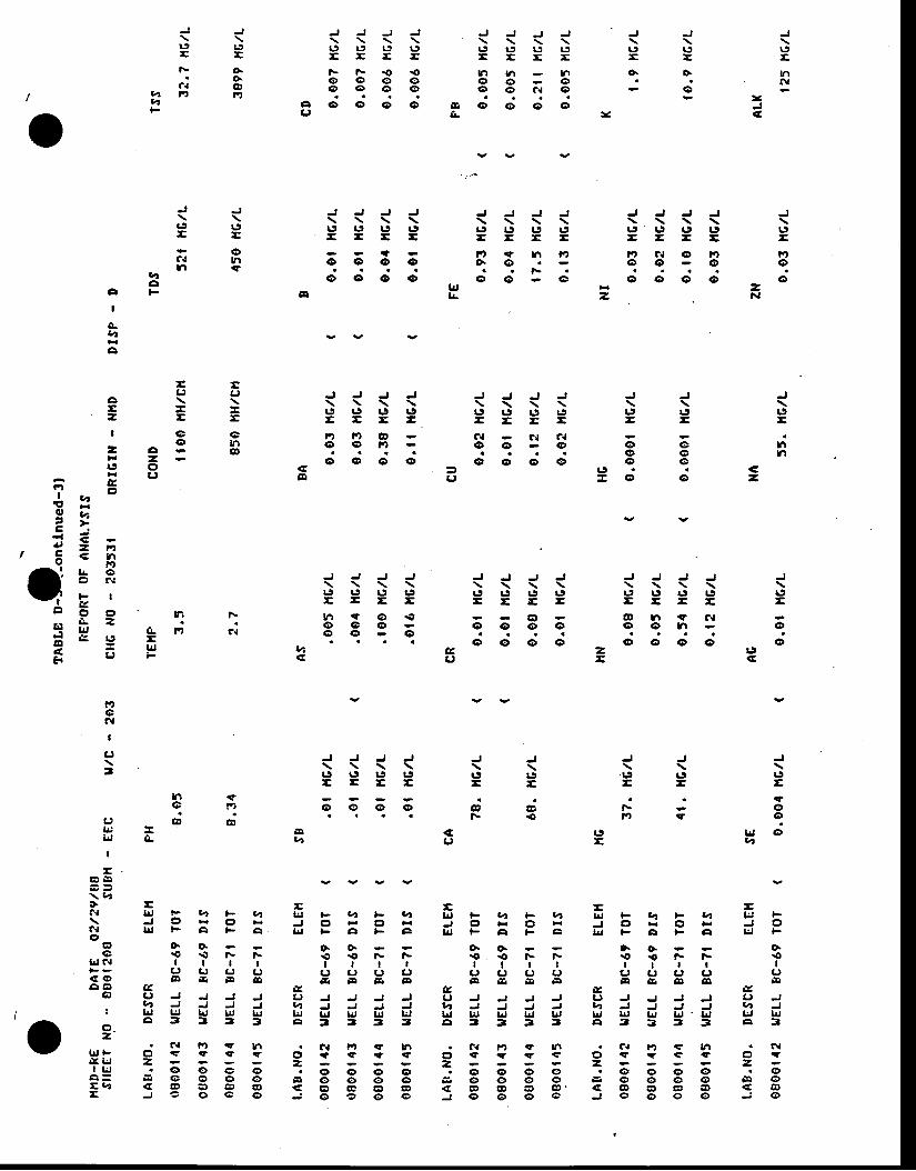
J
uE
tt\l
-
J J J J J J J J J J\ \ \ \ \ \ \ \ \ \IJ I.' L' I' IJ I.:' L' L' IJ t5t a - E - - E = = E
F F . O r O t r . r u . t l | 1 O . O .o o o o o o o . .o o o o o o a { o o -
c o o o o & < D o o oq r a - -
J J\ \r J L tE E
t\ o.. o \
a { @? r F , | 1 tv,
J ! ' J J J J J J J J J J J\ \ \ \ \ \ \ \ \ \ \ \ \r.9 19 rJ |J r5 !9 tl t9 tJ lJ rt rt u- a = - = E = = - - = = =
a - F ' . ? t . l t t l n c { o F t i t( D O ( D ( D O . O O ( D ( D O
FO ( D ( D ( D C G r ? O O O O ( D O
.DH=F
J J\ \t J u- =- ( DC.l Yrt . t ( r
,ao
A F
I
o-a4
c
L'=
rth
€-
J J J J J J J J J J\ \ \ \ \ \ \ \ \ \Lt !f Lt rt t:r r.t Lt Lt u u- = = - = = = - = -ri, Fit o c{ c,t c{o o r o o o o o o. . . . O e
_ o o o o ( D o o o c e< 3 = t J . .E O - o o
J J J J J J J . J J J J J J\ \ \ \ \ \ \ \ \ \ \ \ \r J l t r J r 9 L 5 t j | t 9 t 5 r J l J t . ' L t 1 9= - = - - - r E - = t E - -
& . t s o r O G l @ l . t r l c {O ( D O ( D O O ( D O O I . r - ( DO e ( D . . . . . .. . o o o o o o o o o
4 E z t j< 3 c r = < E
19E
q'oo
lr, Ola
J J\ \.L' IJ- -
FF, rl
19E
J J\ \1.' r.'- -
@ @F . O
€CJ
J J J J\ \ \ \r J r S | 9 | . 9- E - -
t )ocl
I
CJ
3
n €e F '
a ) 8 6i . ' , -li, A-
I
E -l ! F t r F v , I J FJ o H o F J oI J , | F A F A I i I
o . o o .r O . O F F . or a t t l
!, (, L' C' L'E a q J g d q d D
E gL I J J J J t J JV ' J J J J I 4 Jl! lrJ lr, LJ lr,l U, lrJA 7 3 3 3 4 3
- =f J F e ' t F u r t l J F v r F 1 4J O t s c , E J C I H O FL J F A F F I | T F A F C
O . O . 6 6€ . o F F . O . o F Ft r t r r t l t
c . ) L r L r t , c , ( ) L r c ,E E E F F d q E "
E EL ' J J J J C ' J J J JI 4 J J J J V I J J J Jl! LJ t, uJ l, lr, u lrJ lrJ lrjo 3 3 3 3 A 3 3 3 3
-E E
+ -i . f l d ! e 1 F u ,\ J O H C ' ;C . T b , F A F Ao
E O . o .O € . O F F
|JJft | | | |E: L' Ct ct Lt< o F E ! o -A A U
O C ' J J J JV , J J J J
I lrJ lJ lrJ Lu t!a 3 3 3 3
-
Iv
= actq= = *I ( D G
- ag gF r =t 5 0
= c ,F t =
* 2 v! u ,z, it = =| 6 aH
^-,r- L oI o r {- i , t I
E l F g r n Fi L Z
- l, f! llt c{= e , s =z = u JF U F
o o o o
ttaa
v Y v v
. f.l lt <? h . C{ fO t? h . C{ tif rr n . a{ F) € tn . N9ll- e <i ir (r rr g - s ? <t c, s i <r € Oc i r = - -1 uE- E g O O O to o o o o ii o o o o tr o o o o cr O8 , 1 4E J e 0 e o J 6 € ! o o J o o € ' a J o o o o j o
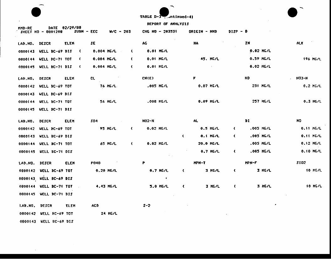
otfl,tD-RE DATE O2/29/8e
.silEET N0 - 0001208 suDll - EEC u/c - 203
'ABLE '_t;rnued_'REPORT OF NNALYSIS
cllc No - ?03531 oRtGtN - NlrD
o-DESCR ELEil
UELL EC-69 DIS (
UELL 8C-?I TOT (
uEt .L BC-?t Dl . l (
SE
0.004 l r6 lL
o.004 i r6 lL
0.004 l rc lL
CL
?6 NG/L
56 nG/L
9s nc/L
65 nGlL
F O40
0.20 l tc lL
4 .43 ] tC lL
ACD
AG
0.0t i lGlL
0.ot t ' r6lL
o .o t l rc lL
C N ( E '
.005 ltclL
.008 HGIL
NO2-N
o.o2 i lGlL
o.o2 l,rclL
o.7 l lG/L
I
5.0 l tc lL
s-?
NA
45. nG/L
0 .07 HGIL
0.09 l rc lL
AL
o . 5 h 6 l L
o. I lrclL
20 .0 xG lL
o.? l l6 lL
HPN.T
3 lrcll
3 itclL
- l )
ZN
O.O? XGIL
o.J9 l r6lL
0.0? l , tc lL
HD
23t l r6lL
257 nC/L
E I
.005 l,lclL
.oo5 t{G/L
.005 lrclL
.005 l lc/L
}IFN.F
3 ltclL
3 lr6/L
196 AG/L
NO3-N
0 .2 l r c l L
o . 3 H G I L
lr0
o. | | l rc lL
0. | | rc lL
0. | 2 lr6lL
0. | 0 l,rclL
s l02
I O HGIL
l0 H6 lL
DISP
LAB.NO.
08001 43
0so0 l 44
0800t 45
LAB. NO.
0800 t 4 t
os00l 43
00001 44
0000 t 45
LA8 .NO.
otr00t 42
0000 t 43
oB00r {4
0800 | 45
LA! . NO.
0000t 42
oB00t 43,
os00t 44
o8o0t 45
DESCR
UELL BC-69
[,ELL 8C-69
UELL EC-?I
L'ELL 8C-?I
DESCR
UELL 8C-69
UELL BC-69
UELL 8C-71
UELL BC-?I
ALT
(
(
(
ELE}I
TOT
Dts
T0'r
D T S
ELEI'I
t0T
D t s
TOT
Dts
s04
DESCR ELEI,I
UELL 8C-69 TOT
uEt-t- gc-ar ors
UELL EC-7I TOT
I,ELL 8C-?t DIS
P
I.,18. NO. DESCR ELEII
0800t42 UELL I rC-69 T0T
0800t43 UELL r ,u-69 Dt .S
?4 lrG/L
(
o
A
I
gVt
c
GE=I
zr9
E? 4 ot , F
975d, D z t tc € h
( g b.q
tt-Fltt9
o F lr go ??
S E u c . lr o = l4 L r v ,F
F'oft
L'
3
(., aL.' i)IJ
I
EE E
$ =i l l ! F U ,\ J Of t l d F , ao
aG F F
I|Jc{ | |F? ( t L t€o E &r la 6 e
o & r - t J' , 4 - : JI lrj tr: lr,
. c , a t 3z
. € t . tlrJl- Ct q ?g a =la: , i . €r O
o = - q o otaa G o GrE J G @
l ^ r .v
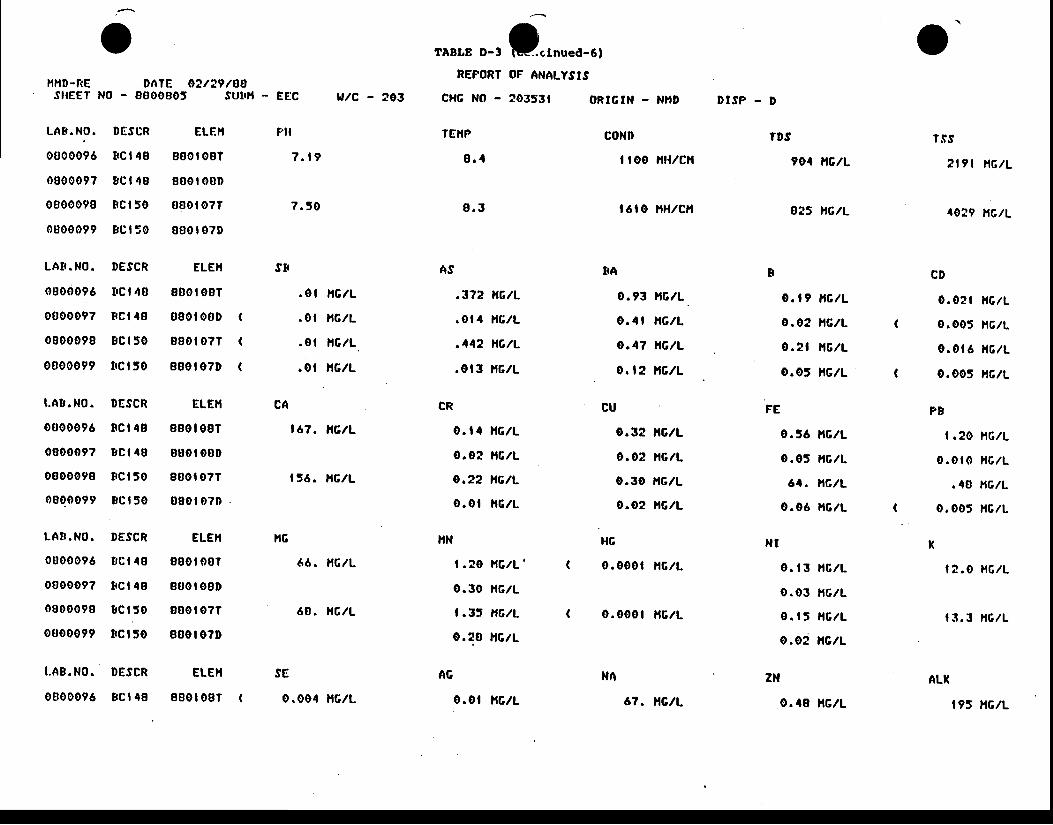
v
l ' fHD-f{E DnT[ O2/29/8ASIEET N0 - 8000s05 sutrH
LA8. N0. I IESCR
0800096 8cl 49
0800097 8c t 48
0800098 8c t50
0800099 Bc t 50
LAB.NO. DESCR
0800096 t tct 48
000009? Bc l48
0800098 Bct 50
0800099 trct 50
I.AB. NO. DESCR
0000096 8c t4s
080009? Bct 40
0800098 8ct50
0000099 tc t50
LAII . NO. DESCR
0000096 t ,C | 48
0800097 tc t4s
0800098 8Ct50
0800099 8ct50
t.A8. N0. DESCR
0800096 Bct 48
ELE}t
880t 087
g00r o0l)
s00t 07t
800t 070
ELE}I
8B0t 007
080t o0D
880t 077
880t 07D
ELE}I
880t 081
890t 08D
ssot 0?T
080t 071)
ELEII
800t 007
s00r osD
oB0t o?T
88ot 0?t)
ELE}I
880t 087
(
(
(
. EEC
Pll
7 . t 9
7 . 5 0
.01 nc /L
.0t l tc lL
.0t l lc lL
.0 t xGlL
167. Ac/L
| 56. tt6lL
66. l tc lL
60. nGlL
SE
0.004 l tc lL
u/c - 203
IABLE o-, O"rnued-6tREFORT OF ANALYSIS
ORTGIN - NI,ID DTSP . D
coNn
| | oo ltH./cll
t6to l tHlclt
FA
0.93 HCIL
o.q l nc lL
o.4? ?IG/L
o, l2 nc /L
CU
0.3? trclL
o.0? lrc lL
o.30 HGIL
0.o2 l t6lL
HG
0.000t l tc lL
o.000t l tc lL
TDS
90' AG/L
425 nc/L
0. | 9 l tc lL
o .o2 nc /L
0 .2 t l t6 lL
0.05 lrG./L
0.56 l tc lL
0.05 l tc lL
64. nc/L
0.06 l tc lL
o . |3 i l c lL
o.o3 l , r6lL
o . | 5 | l c / L
o.02 l tc l l
ASstl
cH6 NO - ?03531
TEIIP
8 . 1
9 . 3
.372 nG/L
. ol4 ltG./L
.442 nGlL
.0t 3 i t6lL
CR
0. | 4 ltclL
o .e? H6 lL
o.22 nc/L
o .0 t l t c lL
lrN
| . ?o itclL '
o.3o ltc./L
f . l t H 6 l t
o.28 l lc l l
AG
0.ot l tc l l
FECA
N Ih6
o't.ts
? l9 l nG/L
4029 HGIL
CD
0.0?t l tc lL
0.005 l t6lL
0 .0 t 6 l t c lL
0.005 l l6 lL
PB
| .20 l t6lL
o . o t 0 I t G l L
.48 l , tc lL
0. 005 l tc lL
x1 2 . 0 H 6 l L
| 3. 3 l rc lL
ALI(
I9J NG|L
NN
67. nc/L
ZN
o.48 l tc l l
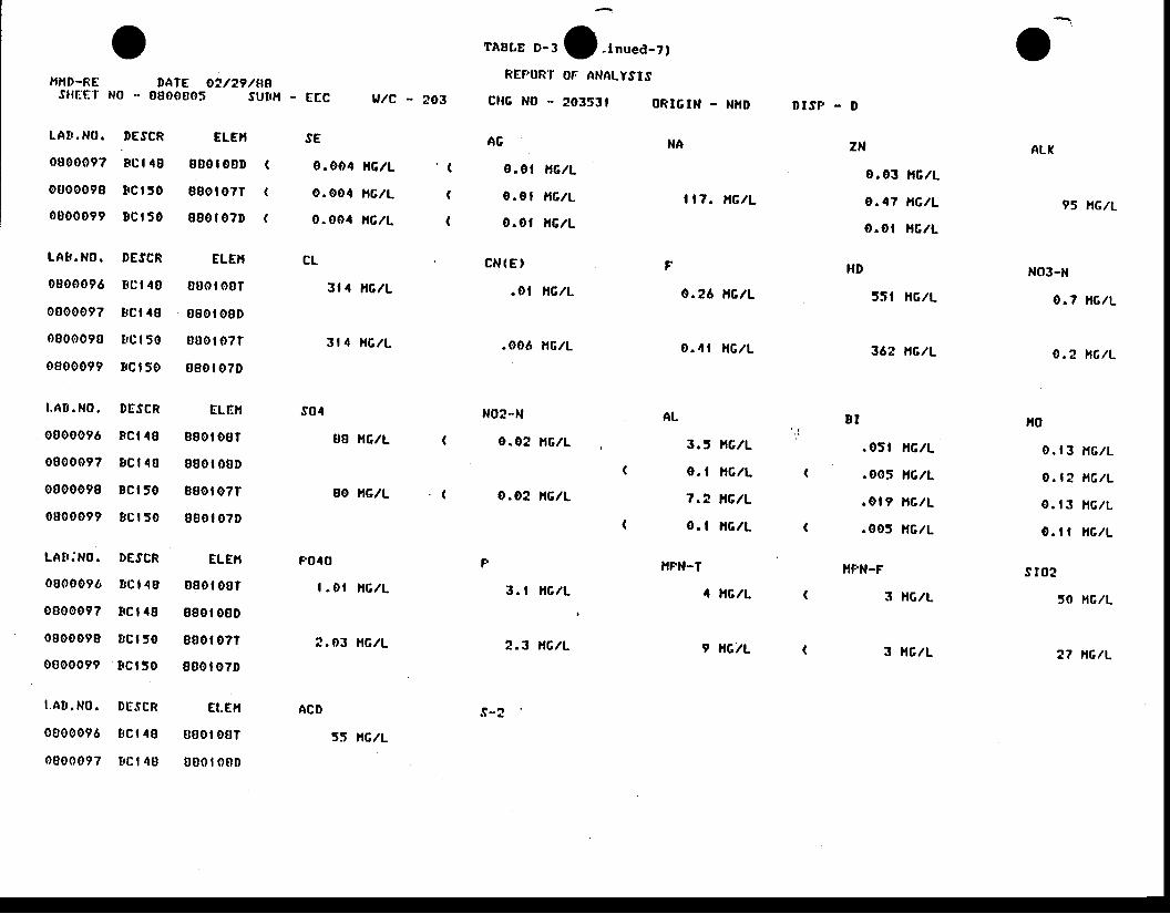
lf lrD-RE DATE O?/29/ensilfitiT No - 0800s05 surH - E IC u/c - ?03
rABLE o-, O-tnued-?tREF,ONT Or ANALYSIS
orc No - 2035t t 0Rt6tN - NHD D I S P - D
LAtt . NO. DESCR
080009? Bct 48
otr00098 8ct 50
0800099 Bct 50
LAB.NO. DESCR
0800096 Fc t 48
0000097 t tc t 48
0800090 t rc | 50
0800099 t c t50
I .AB . NO. DESCR
00000?6 Bct 48
0800097 8ct 40
0800098 Ec t50
0800099 BCt 50
LAII : NO. DESCR
0000096 BCt 40
0800097 8Ct 48
0800098 BCt 50
0 8 0 0 0 9 9 ' 8 c t 5 0
1 .A8 . N0 . DE . iCR
0800096 t rc t 4B
0800097 t 'C | 4B
ELEII
800 t 00D
880t o7T
880t 07D
ELE}I
000 | o8T
080 t 08D
B00 t o?T
B80 t 07D
ELIII
s8o t os t
800 | 00D
880t 07T
800 | 07D
ELEI,I
000 t oo t
880t 00D
800t 0?T
800t o?D
Et.Ell
0Bo t 007
0 0 0 r o B D
SE
0.004 l lc lL
o.oo4 l {c /L
0 .o04 HGIL
CL
3t 4 l tc lL
31 4 HGIL
T'B H6lL
80 ll6./L
FO40
| . 0 r l t c l L
2 .03 l t c l L
ACD
AG
0 . 0 1
o . 0 l
o . o l
C N ( E '
. o l
.006
NG/L
NE/L
NG/L
NG/L
NG/L
N02-l,l
o.02 l tc lL
o .o2 nG/L
F
3. I l tc lL
2 .3 l r c l L
.s-2
NA
I t7 . nc/L
0.26 nG/L
o . 4 l n c / L
ZN
0.03 i lc lL
o .47 nG/L
o.o t l l6 lL
HD
55t ltclL
362 l{cll
E I
.05t t rc lL
.005 H6lL
. ol 9 i lclL
.005 HclL
I,IFN.F
3 HGIL
3 ltclL
95 nG/L
NO3.N
0 . 7 n G / L
o . 2 n c / L
|l0
0. | 3 HG./L
o. | 2 l tc/L
o. | 3 t16lL
0. t | |,tGlL
s I 0 2
50 r,rclL
27 xc /L
ALI((
(
(
(
(
(
s04 AL
3 . 5
0 . 1
7 . 2
o . l
}IPN-T
NG/L
NG/L
NG/L
NG/L
4 UC/L
9 NG/L
55 l\GlL
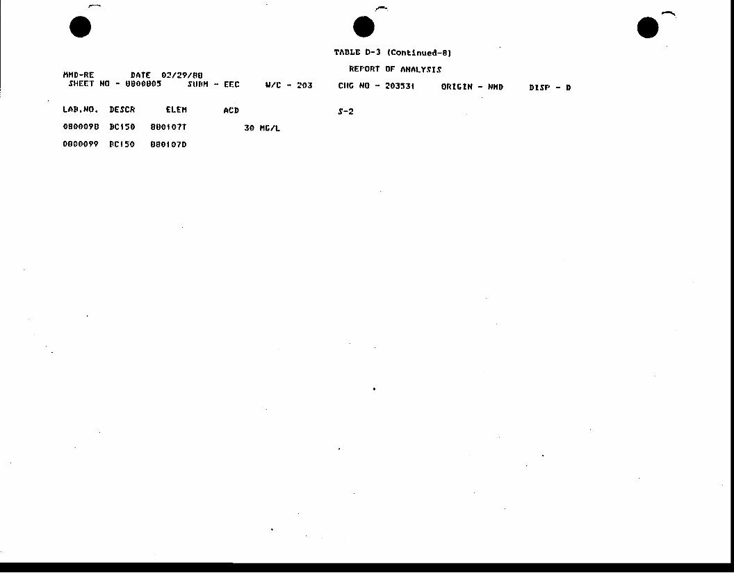
il,tD-RESHEEI' NO
LAT.NO. DESCR ELE}I
08000?0 sc t50 800t0?T
0800099 tc t50 0so to?D
DAIE O?/29/88- 0800805 Stllr l l
TABLE D-3 lcont lnued-Bl
REFORT OF ANAT.Y.fI.S
f l tG NO - 20353t oRlcIN
s-2
- EEC
ACD
u/c - to3 - NHD DlSf , - D
30 r{G/L
APPENDIX GI
SOIL PROFILE DES(RIPUONS
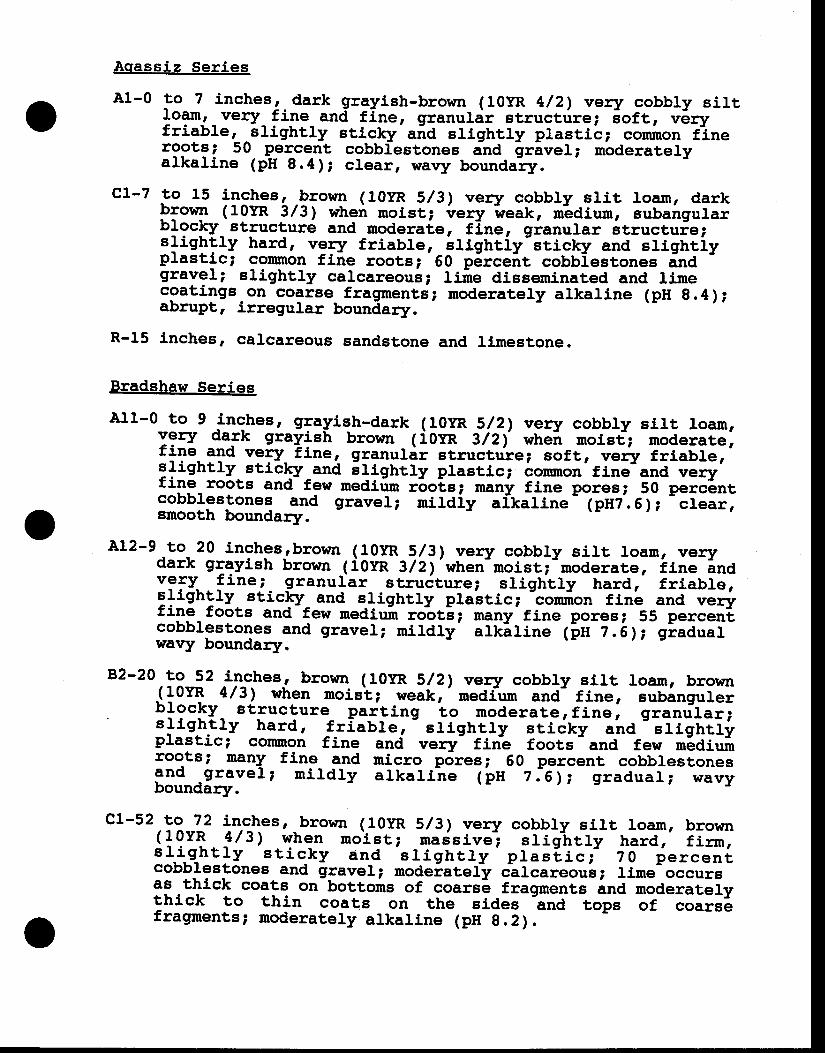
Aqassiz Series
A1-0 to 7 inchesr- dark grayish-brown (10yR 4/21 very cobbly sirtlo"t,, very_ fine and fine, granular structrire; 6oft, v6ryfriable' ^slightly sticklr ana slightly plastiti conmon finergotst 50 p__elcent, cobbrestones and grivel; noderatelyalkaline (pH 8.4); clear, wavy boundail.
-
c1-7 to 15 inches, _brown (10yR s/3, veqz cobbly slit roam, d,arkPT"op ( 10YR 3l3!- when moist; i'"ry i,veak, dedium, subairgulaiu19clv_ structur6 and moderaie, fine, granurar structuie;srightty hard, vgry friable, irightiy-sticky and slightiyplastici conunon fine rootst 50 p5rceit cobbiestones indgravel; slightly calcareous; line disseminated and rirnecoatings on coarse fragmentj; moderatery alkaline (pH g.4);abrupt, irregular boundary.
R-15 inches, carcareous sandstone and limestone.
Bradshaw Series
All-0 to 9 inches, grayish-dark (10yR s/21 very cobbty silt loam,yery da.rk grayish brown ( i0y:n 3/21' whei uroisf; moderate,fine and very- tiner_ granulir structure; soft, verir friabler'stightly. sticky and stigfrtty plastic; conunon'fine'ana v-ry'fine roots and-few mediirn r6ois; .any fine to"""t 50 p"i-6ttcobblestones and graver; mildiy afkaline- (pttz'.51 ;
-.i"ii,smooth boundarT.
A12-9 to 20 inchesrbrown (10yR s/31 very cobbry sirt loam, vea?dark grayish brown lion 3l2y'when-moist; 'nod-rare, i ine inavgII f ine;- granular struiture; slightly hard, friable,slightly. sticklz_ and s_lightly plaitic;
-cornf,on ffrrb and veri
fine foots and-few nediuir robtii nany fine porest 55 percenicobblestones and graver; rnildly atkil ine 1in z.e1; giadoai-wa\ry boundarl.
92-20 to 52 in^ches, brown (10yR s/2,t very cobbly sitt loan, brown_(IOYR 4/3, when nroiet; weakr'nediurn and- fine, sulingur-rbLgclry_ gtructure_ par!,ing to moderate, f ine, granrif aiJsrrghlry hard, fr labre,
- sl ightty sridkt aira
- srighir i ,
plastici conmon fine anci very fini foots -
and few tn6aiurirrootsi manY fine and micro porest 60 percent cobblestones3nd -gravel ; n i rd ly arkat i -ne t bn z i e y; graduar ; *"rvboundary.
c1-52 to 72 inches, brown (10r'R s/3) very cobbty siLt loam, brown(1gY l 4 /3 , qhgn mo is t ; ma is ive - ; s l i g i t l y ha rd , ' f i nn ;s r_ i_g_ht ry s t i c_ky and
-s t ighr ly p tas i , rc ; ' 7 o f e rcen i
cobblestones and gravel; modeiatef-y cifcareouli lime occursas thLck coats on-bottoirs of coars6 fragments ind noaeriiEfythick to thin coats on the sides
-and top" of coar"6
fragnnents; moderately alkal ine (pn g.2).---- - -5-
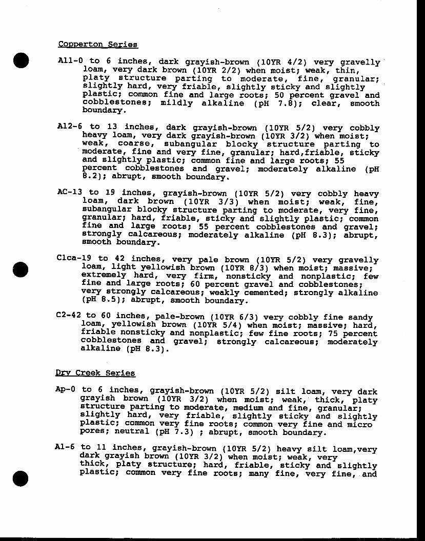
Copperton Series
All-0 to 6 inches, dark grayish-brown (10yR 4/2) very gravellyl9*, vety dark brown- (ftyR 2/2) whdn moist; weakr- tf,in,Pl?t^V _ structure pard, ing to moderate, f ine, l l ranular;slightly hard, very friabie, slightly sticky and'srlghtlyprastici conmon fine and rarge iootJ; 50 percent grivel-andcobb les tones ; n i ld ly a lka f ine (p l t 2 .6 ) ; c rea t , smoothboundary.
A12-5 to 13 inches, dark grayish-brown (roy-R s/2, vea^lz cobblyheavy loam, very dark grayistr-brown 1iotr, 3/2r'when
-uroist;
weakr coar€e, subanguJ.ar blocky -
structuie parting to'moderate, fine and verT fine, granular; hardrfriable, sticky
and slLghtJ.y -plastic; -onunon fine and large rootst 55percent cobbrestones and gravel; moderateLy arkaline (pltg.2r; abrupt, smooth boundary.
Ac-13 to 19 -inches, grayish-brown (toy-R s/2) very cobbty heavylo_arn, dark brown
- ( 1OyR 3/3\ when io ist i weak,- f inel
subangular blocklz stiucture paiting to moderate, very fine,granular_; hard, friabre, sticky and slightly plastici-conmonfine and large rootst 55 perlent cobblestbn-es and gravel;strongly carcareousp noderitely arkarine (pH 9.3); ibrupt,smooth boundary.
clca-l9 to 42- inches, veafz pale brown (10yR s/2) very gravellyroam, l ight yellowish bt'own (10yR ei:1 rvhen moist;-mSssive;-extrenely_ hard, very firm,
'nonsticky and nonplastic; f6w
fine and large rootsi go percent grav6l and cob6lestones;veraz strongly calcareousl weakly ienrented; strongty alkaline(pH 8.5); abrupt, smooth boundailr.
c2-42 to 60 inchesr_pale-bro!i ln (l0yR 6/31 very cobbly fine sandy1o?r-'_yerlowish brown (10yl' s/4') wlien n6ist; missive; har&,friable nonsticklr and nbnplastici few fine rootsl. 75 percenicobblestor-re_g _ald graveli strongJ.y calcareous; modSratelya lka l ine (pH 8 .3) .
Drrr Creek Series
Ap-O to 6 inches, gray_ish-brown (l0yR s/21 sirt loam, very darkgrayish brown - ( lOYR 3/2, when uroisi,l weak, thick,
- platy
Etructure -parting to modeiate, rnediun and flne, granulai;slightly hard, verar friable, slightly sticky' jnd sligfrtfyplastici common very fine roots; c'ornmo-n very iine and micro-pores; neutral (pH 2.3) ; abrupt, smooth boundary.
A1-5 to 11 inchesr- grayish_-brown (lOyR S/2) hearryr silt loamrvery9-"Tk- grayish brown ( 10yR 3 / 2,)' when rnoi'st; weik, vea-lztttick, platy struct'ure; har6, friable,
-sticky and-srightly
plastici cormon very fine roiltsi many fine, -r"ry
finei .tt&
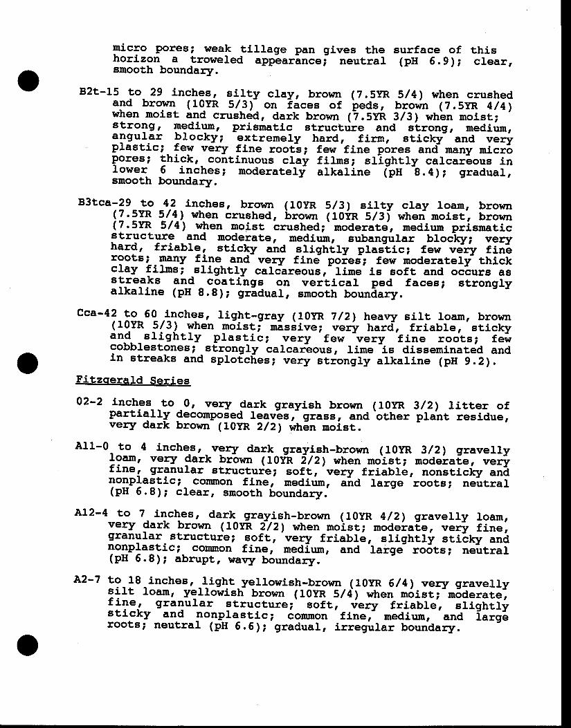
micro poresi weak tillage pan gives the surface of thishorizon a troweled appearancei neutral (pn G.9); clear,snooth boundary.
B2t-15 to 29 inctres, si. lty clay, brown (?.5y-R s/4) when crushedand brown (10.yR 5/_3)- on l ices of ieds, brorin (?.5yR 4/4,when nroist and crushdd, dark brown 1?.svi 3/31 whbn moist;
'strongr medium, prismatic structure and etrong, mediurn,angular blocky; extremery hard, f irm, eticky' and vea?prastici- f"y very fine rootl; few fine pores and many rnicr6Pores; thickr continuous clay filrns; slightly calcar6ous inlower 5 inches; noderaterli arkaline ipn i.e); gradual,smooth boundary.
B3tca-29 to .4.?.inches, brown (10yR s/31 silty clay roam, brown(Z.IYR 5_/!-l w\en crushed, brown (loiR s/3, wheri'noist, brown(7.5YR 5/4't wlren moist crushed;'noderate, medium prisrnaticstructure and moderate, mediun, eubangular broc-lqr; veryhard, friable, sricky airA slighily plasltc; few veii ftn6rootsi nany fine and vealz fine poiee; few moderately-thickclay fi lms; slightly calcireousr l irne-is soft and occurs asstreaks and coatings on vertical ped faces; stronglyaLkaline (pH 8.8); grldual, surooth boun&ary.
cca-42 to 50,inches, l ight-gray (10yR 7/21 heavy silt loam, brown(10yR S/3) yhen rnoist; mlsiive; ved, hard, friable, srickyand sl ight ly prast ic i very few very f ine roots; fe icobblestones; strongly calcarlous, lirne is disseminated andin streaks and sprofcf,es; very strongry alkaline (pH 9.2).
Fitzoerald Series
02-2 inches to.0, very fark grayish brown (10yR 3/2,) l i tter ofpartially
9ecornposgd leav-es, grass, and'other plaht residue,vea'lz dark brown (10yR 2/Z) wfr5n moist
All-0 to 4 inche,s, - vgry dark grayish-brown ( lOyR 3/2,) gravellylo*' vea'rz fark brown (10fr itzy when noist; modela[e, n;+fine, granuJ.ar structuie; soft,'ver7 friabli, nonsticliy an&nonprastic; cornmon fine, nedirim, a-nd large roots; ne-utrar(pH 6.8); c lear, smooth boundary.
412-4 to 7 ilches, dar_k- grayish-brown (10yR 4/2,) gravelly roam,very 9ark prown (10yR f/zy when moist; modeiaf,e, veri fine,granular- structure; soft, veaar friable, slightly stiify ininonplastic; corunon fine. medlum, and
'large- ro6ts; ne-utral
(pH 6.8); abrupt, wary boundary.-
A2-7 to 18 inchesr -light-yerlowish-brown (10yR 6/4y very gravellysilt loam, yellowish brorsn (10YR Sldy when m5ist;-n5derate',f lT"r granurar structure; soft, r"ry friabls, srighirj,sticky and 3ongla-slic; iomnon finer- nedium,
'and i irg6
roots; neutral (pH 6.6); gradual, iregular boundary.
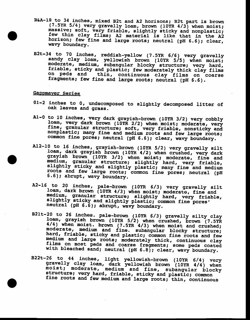
B&A-18 to 34_ilches, nixed B2t and A2 horizonsi B2t part is brown(7.5YR 5/41-very gravelry roam, brown (tOilR 4/3-,, when moistjmassivei eoft, v-e-ry friaLre, siigtrtty itictcy an6 nonprasticifew thin clay filhs ? A2 nateriil is like that in- ttre A2hor izoni fewt ine and rarge roots; neutral (pu 6.5); creai ,wav1r boundary.
B2t-34 to 70- inches, reddish-yerlow (z.5yR 6/61 very graverlysandy clay l-9*, yellowi-sh bror"ir ( 10yR SlSl wf,eri nroist';moderate, ng{iun, subangular blocky' structur6; very hard,friable, sticJcy and pras[,ic; few moderarery ittiir. cla:y fil;;on peds and thin, cont inuous clay
- f i rms on coarse
fragments; few fine and targe root'; neulrar (pH G.G).
Gappmaver Series
0L-2 inches to 0r undecomposed to elightly decomposed litter ofoak leaves and grass.
A1-0 to 10 inchee., yeTy dark grayigtr-brown (10y-R g/2,) very cobbryl9*' very $ark brown (ftyf ?/2') when'noistl-m6deraie, n;+fine, granular structuie;- eoft,'ver1, friabl6, nonsticf.y a"lnonprastic; nany fine and mediun roots and f6w riige i'.r"i";cormron fine pores; neutral (pH G.G); clear, waqr uoindary.-'
A12-10 to 15 inchesr.g-ra_yish-brown (lOyR s/2,) very gravelry siltloam, dark grayiJh 6ror,m ( royR' 4rr) whei .ro'"rrEa, .r;+ d;;igray- ish brown_ ( l0yR 3/21' when noist; moderate, f in--e andutg{iun, granulai structu're; slightry' il;d;- .r"ry friable,slightry
.stic\r- and slightty pia6tici nany'fine Lnd mediumroots and few large rools;-c6rnnron fine p-ores; neutrar (pn6 . 6 ) ; abrupt, wavy-boundarlr.
A2-15 to 20 _inches, p_ale-brown (10yR 6/3,) very gravelly sirtroam, dark brown [rovr, 4/31 *ir"n-r"ist;'nodeiat-e, fine andng9ignr granuJ.ar
'EtructurAi eltghtry' r,"ta,
-.;'ty friable,
slightly."_!f9*y and sltghtfi plas€ici common fine pores,neutral (pH 6.6); abrupt, wavi boundiryo
B21t-20 ro 26 i:n*":. pale-!,rown {10yR 6/31 gravelly silty clay*9?T, __glaVish brown ( 10IF _S/2,, .qt "t
crushed, 6ro*n 12. svi1l4l when moiet. brorin (7.5yR 'Q/3,
when noisl and crrished;moderate, medium and t'tne. subairg"Iii tG-.Ly Etructureihard, friablg, etic\r and prastic; common fine roots and fewmedium and large robte; ioderat_ely thick, continuous .l;tfilms on lnos_t peds and coarse frigments; Bome peds coai"&with bleached sind; neutral (pH 6.gi; clear, navt' boundary.-
B22i-26 to 44 _inch_es, l ight yellowish-brown (loyR 6/4,) vezygravelly cl.ay loam, aelt -yellgwigfr
brown '(-t-0y-R
l ti\ ,orr.i.moist; noderat_e, nedium- and f ine. J"ui"g"rai -6r;; i t
structure; very-hard, friabJ.e, sticky ind plasfic; conmonfine roots and-few nidiun and large ioots;-thin, continuous
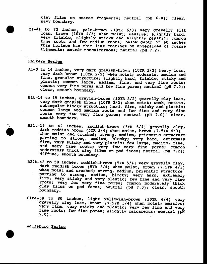
o
clay fi lsrs on coarae fragments; neutrar (pn G.8); crear,wa\4y boundary.
c1-44 to 72 inches, pale-brown (10yR 6/31 ver1' gravelry siltloarn, \qg ( 10Yr 4/ 3l when inoist; maisive;- siightrf hard,Ygry friable' etightl i sticklz and slightly-plastici- conmonfine roots and few nreaium r5ots; belo-w a6p€n of 50 inchesthis horizon has thin lime coatings on und6rsides of coarsefragments; matrix noncalcareoua; n-eutral (pH ?.2).
Harkers Series
A1-0 to 14 Lnches, vea? dark grayish-brown (10yR 3/21 heavy roam,Ygry dark h_rovm (10YR 2I2)
-when moistj moderat5, medlun and
fine'^granular stiucture; 'stigrrtty
harb, friablel sticklz andplastici cormron rarge, irediuin, f-ine, ind verlz fine r6ots;conmon very. 5$" pores and few fine pores; neudral (pH ?.0 );clear, smooth boundary.
Blt-14 to 19 inches, grgyish-brown (loyR s/2,t gravelry clay roarn,vely dark glgyish biown (t0yR itzy when'n5ist; wlak, rtediurn,subangular blocky structrire; hard, firrr, sticky and plasticiconnon large_ and mediun roots aira few fine
-and v5ry fini
roots vetaz -few veqr fine pores; neutral (ptt ?.0), ?lear,smooth boundary.
B21t-19 to !?. inches, reddish-brown (5yR sl4) gravelly cray,dark reddish brown (5YR 3/4, when nioist, ur6nri fz.sra' 4lat''when moist and crushed; stiong, nediun, pii"rrad,ic structrireParting to B-tTong, medium,
-btocky; ti.w hard, extremery
firm, very gticky lnd very plastic;'ie, la?ge, ,"di.-, fine',and vea? f ine roots t vary few very f irie pores i cotnmonmoderatery thi-ck- clay-fitrnj on ped fales; neutlral tpn 7.2ridiffuse, smooth boundary.
B22t-42 to 58-.inches, reddish-brown (5yR s/4,) very gravelly clay,dark reddish brown-(5-yR 3/41 wiren moist, bioil ir (z.siR 4/giwhen nroist and crushid; etrong, nediun, prismatic-structureparting to i!"grg, medium,
-61ocky;-v6ry hard, extremery
f itmr very sticky- and vely -plastic-;
f ew iine an'a vearz f in6rootst Y"ty few verfz fine poresi cotunon moderately thick-clay _ fi lns on ped ftces; n6utrai (pH 2.0 ); crearr- smoothboundary.
clca-58 to 80 _inches, lJ.ght yellowish-brown (tOyR 6/4y verygravelJ.y clay loamr- biown I z . 5tr sl 4l when
' moist; nissive';
ygry f irur, v_eafz qticky and ' plastic; {rery few f in6 and ve+
fine roots; few fine liores; irigltry calJareous; neutrar (pir7 .0 ) .
'
I{allsburq Series
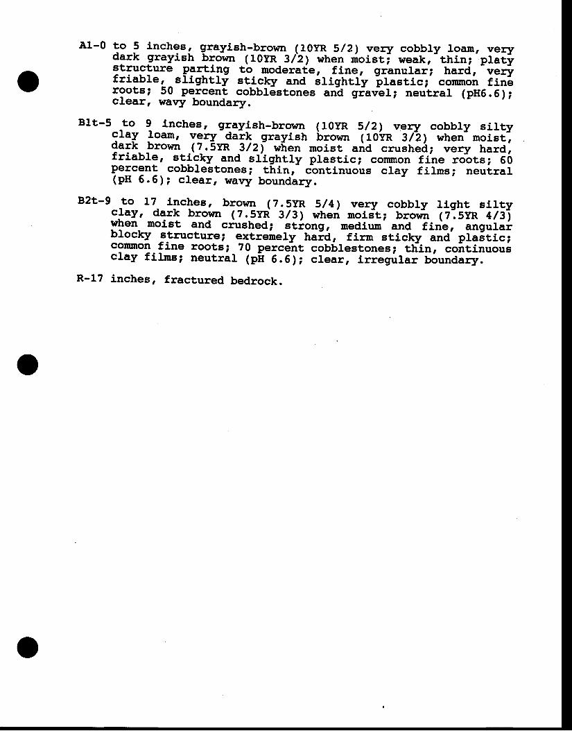
A1-0 to 5 inches, grayish-b_rown (10yR s/2,) very cobbry loam, verydSrk grayish blown (10yR sizy when ioisti weakr-rhin;'prit istructure p+ilg to noderate, fine, glranular; hard,
-vef
friable, _ slightly stj.cky and ifightfy -ptastici'
corunon fin6rootst 50 percent cobbrestones and giavLt; neulrar (pH6.G);clear, wavy boundary.
B1t-5 to 9 Lnchesr 9{a}ish-brorm (10yR s/2, very cobbly sittygray lo*' vgry
-dark grayish trown ( 10vR sliy wheri morsi',
dark brown -(].5tr 3/21 wlren moist aria crushedi very hard,friable' sgigky and slightry prastic; conmon tihe rdotsr 50percent cob_blestones; thinr- cbntinuous cray films; neutrar(pH 5.6); clear, wavy boundary.
B2t-9 to t7 Lnclres, brown (?.5yR sl4) very cobbly tighr silty"1"y,
dqrT brown (?._syB 3/31 wheri noiit; brow?r (?:5y? itsiwhen moLst and cirshed; stiong, med,ium and fin'e, anguraiblocky structure; extrenely rraii, firm
"ti.ry-and' praitic;
coMlon fine roots, 70 percent cobblestones; thin, coirtinuouiclay films; neutral lptt e .e 1; clear, irregular u6unaaraz.
R-17 inches, fractured bedrock.
Harker-Dry Creek

CHEMTECHCHEM I CAL AND BACTER IO LOG I CAL ANAITS€S
367 SOUTH COMMERCE LOOPOREM. UTAH 84057
(801) 226-8822
2875 MAINSUITE #101
SALT LAKE CrTl gt46 3a11t(801 ) 483-1162
CLIENT : JBR Consu l t an t s865 So . Ceda r . Kno l l s Wes tCeda r C i t y , UT e47ZO
LAB NO. UO234A4
LOCATION: Ba r .ney ' s Canyon - BC-RAP- 11
CERTIFTCATE OF ANALYS-IS
PARAHETER
p H U n i t s
CEC t1eqt1OA9
C h l o r . i d e a s C l , m g / l ( g
O n g a n i c H a t t e r . , %
N i t r a t e a s N O g , - N , m g / K g
P h o s p h o r u s a s P O . c - p , m g / K g
P o t a s s i u m a s K , m g / K g
C a l c i u t m a s C a , n g / R g
Magnes i un as Hg, rng . /Kg
Z i n c a s Z r t , m g / K g
C o p p e r a s C u , m g / K g
S u l { a t e a B S O . a r m g / K g
S o d i u m a s N a , m g / K g
f r o r r a s F e , m g / K g
C o n d u c t i v i t y , u m h o s / c n t
? 6 S a t u r a t i o n
LEVEL
7.2e
2 6 , 6
l 0 6
r .31
9 9 0
t . 9
t 9 4
t ,o2o809
o.g
5 . 1
1 r 7 3 O
t 8 l
244
4 1 6
€ 4 . 5
N o t e : l Y ' l e t a l s ( C u , F e , Z n , - C a , K , I ' t g ) d e t e r m i n e d o n D p T A e x t r . a c t .
{&.=-.---R e x H e n d e r s o n
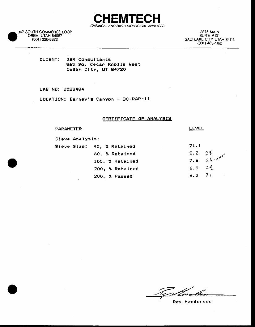
GHEMTECHCH EM ICAL AND MCTEH I OLOG ICAL ANATYSES
367 SOTJTH COMMERCE LOOPOREM, UTAH 84057
(80112264822
2875 MAINSUITE #101
SALT TAKE CITY UTAH 84115(801) 483-1162
CLIENT : JBR Consu l t an t s865 So . Cedar Kno l l s t r l es tCedar C i t y , UT 84720
LAB NO: UO234B4
LOCATION: Ba rney ' s Canyon - BC-RAP-11
CERTIFICATE OF ANALYSIS
PARAHETER
S i e v e A n a l y s i s :
S i e v e S i z e : 4 0 ,
6 o t
1 0 0 .
2 O O ,
2 O O ,
% R e t a i n e d
% Reta i r red
% R e t a i n e d
% R e t a i n e d
% Passed
LEVEL
7 l . t
a.2 3 ( . ( .7 .6 lu " , r / "
6 .e t tL
6 .2 2 r
' Rex Herrder 'son
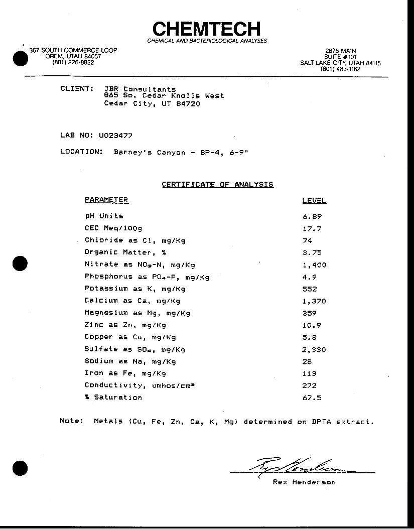
CHEMTECHCHEM ICAL AND BACTERIOLOGICAL ANATYSES
367 SOUTH COMMERCE LOOPOREM. UTAH 84057
(8O1) 22G8822
2875 MA|NSUITE #101
SALT LAKE CITY UTAH 84115(801 ) 483-1162
CLIENT: JBR Cor rsu t t an ts865 So . Ceda r Kno l lE Wes tCeda r C i t y , UT e47ZO
LAB NOi UO23477
LOCATION! Ba r ' ney ' s C a n y o n - B P - 4 , 6 - 9 "
CERTIFICATE OF ANALYSIS
PARAFlETER
pH Un i t s
CEC t ' leq/ lOGg
Ch lon ide as C1 , r ng /Kg
Or .gan i c Ha t te r . , %
N i t r a te as NOg-N , ng lKg
Phosphorus as PO4-p , mg /KgPo tass iun as K , mg /Kg
Ca lc i um as Ca , ng lKg
l ' lagnes iurn as l ' lg , mglKg
Z inc as Zn , mg /Kg
Coppen as Cu , rng /Kg
Su l {a te as SO. , ng lKg
Sod iu rn as Na , rng /Kg
f r ' on as Fe , mg /Kg
Conduc t i v i t y , umhos . / c r r r s
1 Sa tu ra t i on
LEVEL
6 .e9
17 .7
74
3 . 75
l r 4OO
4 .9
552
1 r37O
359
10 .9
5 .9
2 r33O
2A
113
272
67 .3
No te : l ' l e t a l s ( cu , Fe , zn , ca , K , F , l g ) de te rm i r r ed on DPTA e : x t r . ac t .
R e x H e r r d e r ' s o n
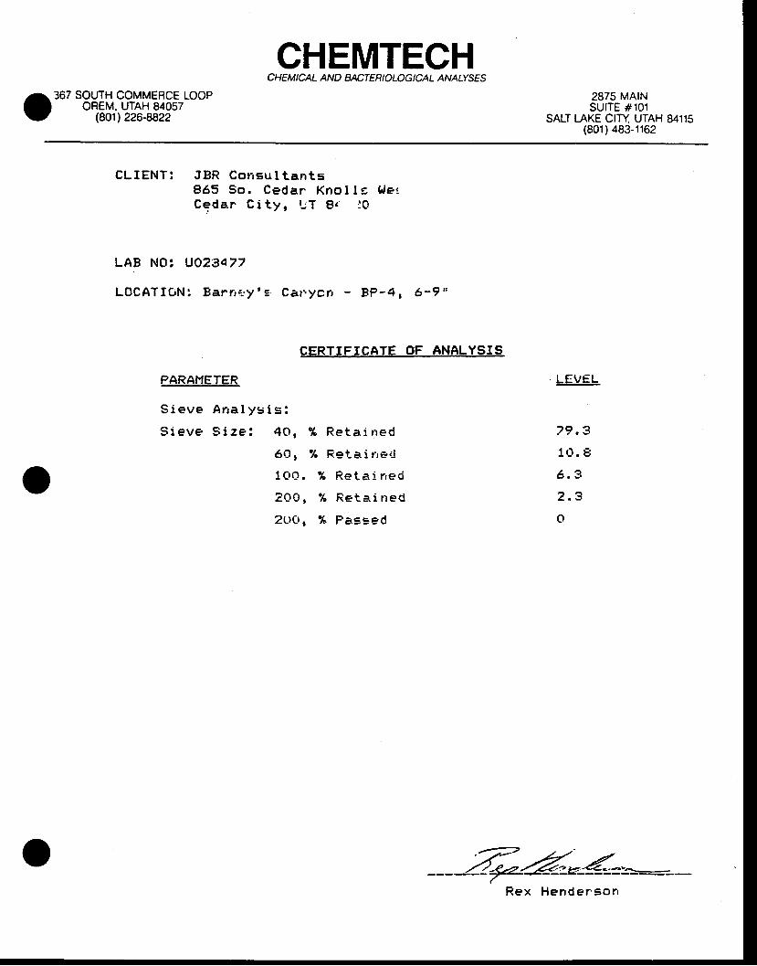
CHEMTECHCHEM I CAL AN D BACTER I OLOG I CAL ANATYSES
367 SOUTH COMMERCE LOOPOREM. UTAH 84057
(801) 226-8822
2875 MAINSUITE #101
SALT I.AKE CITY UTAH 84115(801) 483-1162
CLIENT : JBR Consu l t an t s865 So . Cedar Kno I l = b le tCedan C i tY r rrT f lr ' :0
LAB NOi UQ2:3477
L O C A T I G N : E a r n i - . y ' s C a r . y c n - B P - 4 , 6 - 9 "
CERTIFICATE OF ANALYSIS
PARAHETER
S ieve Ana l ys i s :
S ieve S i ze : 40 ,
6 Q t
100 ,
20O,
2LtO r
% R e t a i n e d
% Fe i -a i r re t l
% R e t a i n e d
% R e t a i n e d
% P a E s e d
LEVEL
79 .3
10 . E
6 ,3
2 .3
o
R e x

CHEMTECHCHEMICAL AN D BACTEB IOLOG ICAL ANATYSES
367 SOUTH COMMERCE LOOPOREM, UTAH 84057
(801',) 226-8822
2875 MAtNSUITE #101
SALT I.AKE CITY UTAH 84115(801) 483-1162
CLIENT : JBR Consu l t an t s865 So, Cedar . Kno l l s t r f estCeda r C i t y , UT e472O
LAB NO: UO2347A
LOCATI0N i Bar . r tey ' = C a r r y o n B P - 1 , Q - 4 I '
CERTIFICATE OF ANALYSIS
PARAI'IETER
p H U n i t s
C E C M e q / l O O 9
C h l o r i d e a s C 1 , m g / l ( g
O r g a n i c F l a t t e r . , %
N i t n a t e a s N O a - N , m g / K g
P h o s p h o r u s a s P O € - p , m g l K g
P o t a s s i u m a s K , n g / K g
C a l c i u m a s C a , r n g l K g
l ' lagnesi l tm as l . lg, rnglKg
T i n c a s Z n , m g / K g
C o p p e n a s C u , m g / K g
S u l { a t e a E S O . , m g / K g
S o d i u r n a s N a , m g / K g
I r o n a s F e , m g / K g
C o n d u c t i v i t y , u m h o s l c m .
I S a t u r a t i o r r
N o t e : N e t a l s ( C u , F e , Z n , C a , K , F l g ) d e t e r ' m i n e d
LEVEL
6 . 5 5
2 4 . 3
l g o
1 . 6 4
7 r 2 7 Q
t t , 7
588
1 , 2 1 O
3 4 9
1 6 . 6
6 5 . 2
9 0 4
4 4
l g o
1 8 3
5 9 . 3
o h D P T A e x t r ' a c t ,
R e x H e n d e r s o r r
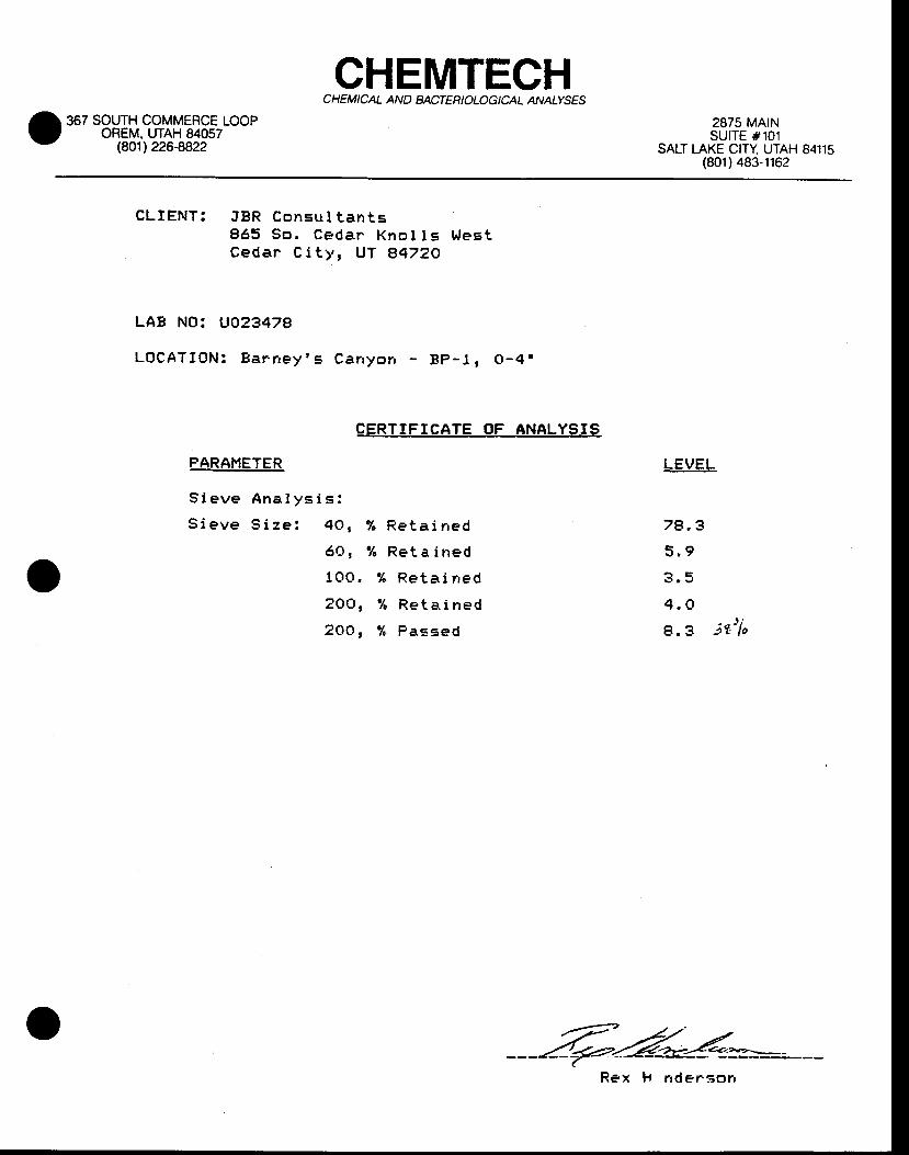
CHEMTECHCH EM ICAL AN D BACTER I OLOG I CAL ANATYSE'S
367 SOUTH COMMERCE LOOPOREM. UTAH 84057
(8O1) 226-8822
2875 MAINsurTE #101
SALT I-AKE CITY UTAH 84115(801) 483-1162
CLIENT : JBR Consu l t an t s865 So . Cedar Kno I I s h tes tCedar C i t y , UT A4ZZO
LAB NOz UO2347A
LOCATION: Ba r r rey ' s Canyo r r - Bp -1 , O -4 ,
CERTIFICATE OF ANALYSIS
PARANETER
S i e v e A n a l y s i s :
S i e v e S i z e : 4 0 ,
6 Q t
100 .
2OO,
2OO,
% R e t a l n e d
% R e t a i n e d
% R e t a i n e d
% R e t a i n e d
% P a s s e d
LEVEL
78 ,3
5 .9
3 .5
4 .Ol l
8 .3 i t ' l o
R e x H n d e r : ' o n

CHEMTECHCHEM I CAL AN D BACTER I OLOG I CAL ANATYSES
367 SOUTH COMMERCE LOOPOREM. UTAH 84057
{8O1) 226-8822
2875 MA|NsutTE #101
SALT I-AKE CITY UTAH 84115(801) 483-1162
CLIENT : JBR Consu l t an t s865 So . Cedar Kno l l s t r l es tCedar . C i t y , UT 84720
LAB NO; UO2348O
L O C A T I 0 N : B a r . r r e y ' s C a n y o n - B C - L e a c h P a d S u t b s o i l
CERTIFICATE OF ANALYSIS
FARANETER
p H U n i t s
C E C H e q / l O O g
C h l o r i d i a s C l , m 9 / K 9
0 r . g a n i c l ' l a t t e r , %
N i t r ' a t e a s N O g - N , m g / K q
P l ' r c s p l r o r u s a s P O r - P , m g / K g
F o t a s s i u m a s K , m g / K g
C a l c i u n a s C a , n g l K g
I ' t a g n e s i u m a s M g , m g / H g
T i n c a g 7 n , m g / K g
C o p p e r ' a s C u , m g / K g
E u t l { a t e a s S O . l r n g / R g
Sod iu tm as l . la , mg/Kg
f r ' o n a s F e , m g / R g
C o n d u c t i v i t y , u m h o s / c n r g
% S a t u r a t i o n
LEVEL
7 . 7 3
7 . 4 9
1 2 5
o , 605
745
1 .1
32
l r28O
263
o ,8
2 .2
505
30
13 .4
311
47 .2
N o t e : H e t a l s ( C u , F e , Z n , C a , K r F l g ) d e t e r m i r r e d o n D P T A e x t r ' a c t ,
Rex Hende rson
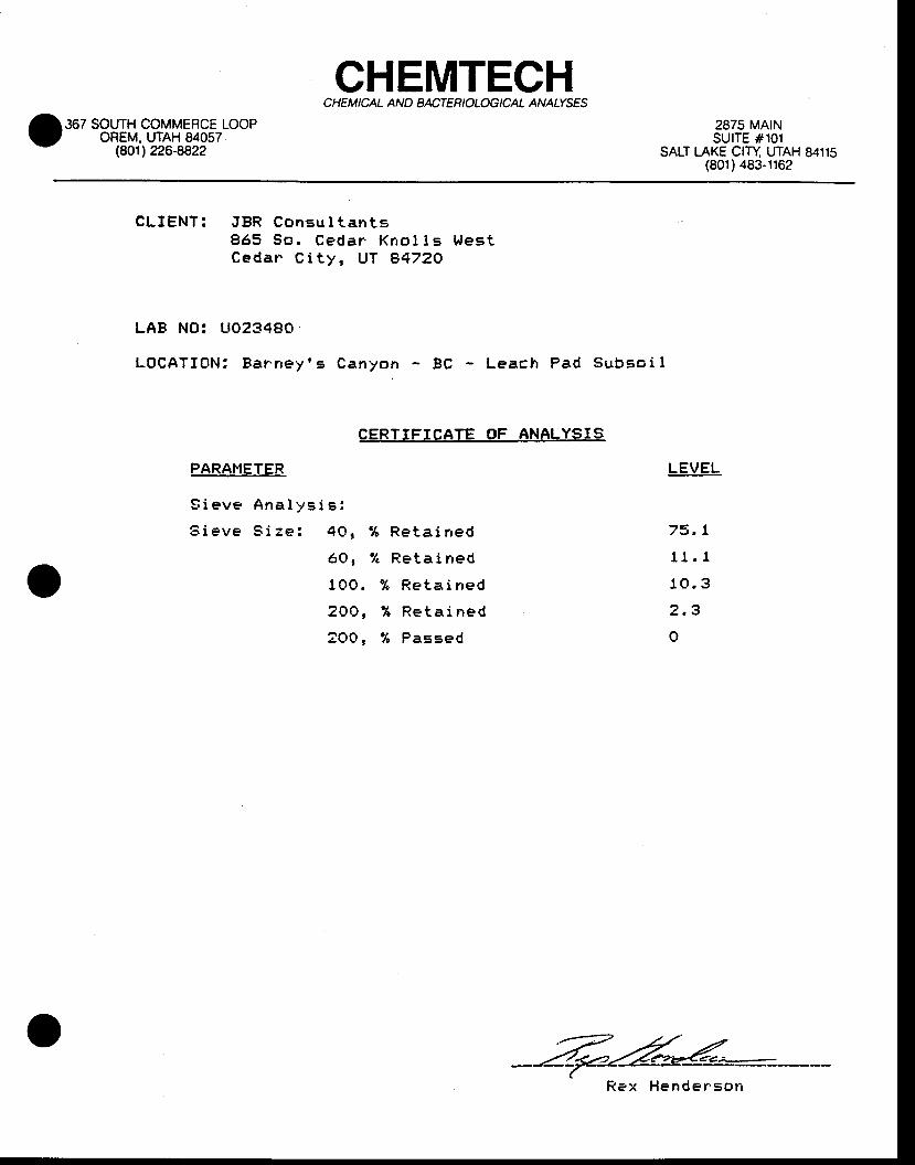
CHEMTECHCHEMICAL AND MCTERIOLOG ICAL ANAIYSES
367 SOUTH COMMERCE LOOPOREM, UTAH 84057
(801',) 226-8822
2875 MArNSUITE #101
SALT I-AKE CITY UTAH 84115(801 ) 483-1162
CLIENT : JBR Consu l t an t s865 So . Ceda r Kno l l s t l eE tCeda r C i t y , UT A472O
LAB NO: UO2348O
LOCATION: Ba rney ' s Canyon - BC Leach Pad Subso i l
CERTIFICATE OF ANALYSIS
PARAI"IETER
S i e v e A n a l y s i s :
S i e v e S i z e : 4 0 , % R e t a i n e d
6 Q , % R e t a i n e d
1 O O . % R e t a i n e d
2 0 O , % R e t a i n e d
2 O O , % P a = s e d
LEVEL
73 . t
11 .1
to .3
2 .3
o
Rex Hender ' son
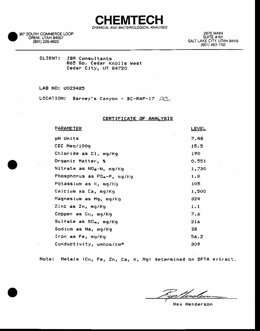
CHEMTECHCHEMICAL AND BACTERIOLOGICAL ANATYSES
367 SOUTH COMMERCE LOOPOREM. UTAH 84057
(8O1) 226-8822
2875 MAINSUITE #101
SALT LAKE CITY UTAH 84115(801) 483-1162
CLIENT : JBR Consu l t an t s865 So. Cedar . Knol I s t r festCeda r C i t y , UT e47ZO
LAB NO: UO23485
LOCATION: Ea rney ' s Canyon - BC-RAP-17 .W_
EERLIFICATE OF ANALYSIS
PARANETER
p H U n i t s
CEC l' ' leq/ I CtOg
C h l o r i d e a s C l , m g / K g
O r g a n i c F l a t t e r ' , %
N i t n a t e a s N O g - N , m g l K g
Phosphonus as FOr-p 1 t *g l f ig
Potass i urm a.s l ( , nrg/Kg
C a l c i n m a . s C a , m g / K g
H a g r r e s i u m a s M g , m g / K g
Z i n c a s Z n , m g / K 9
C o p p e r . a s C u , m g / K g
S u l f a t e a s S O a r m g / K g
S o d i n m a s N a , m g / K g
f r ' o n a s F e , m g l K g
C o n d u c t i v i t y r u n h o s / c r n 3
LEVEL
7 .48
15 . 5
190
o ,551
l r73O
1 .8
105
l r5OO
324
r ,17 .6
216
38
36 .2
309
N o t e : F l e t a l s ( C u , F e , Z n , C a , K , l ' , t g ) d e t e r m i n e d o n D P T A e x t r a c t .
R e x H e n d e r ' s o n
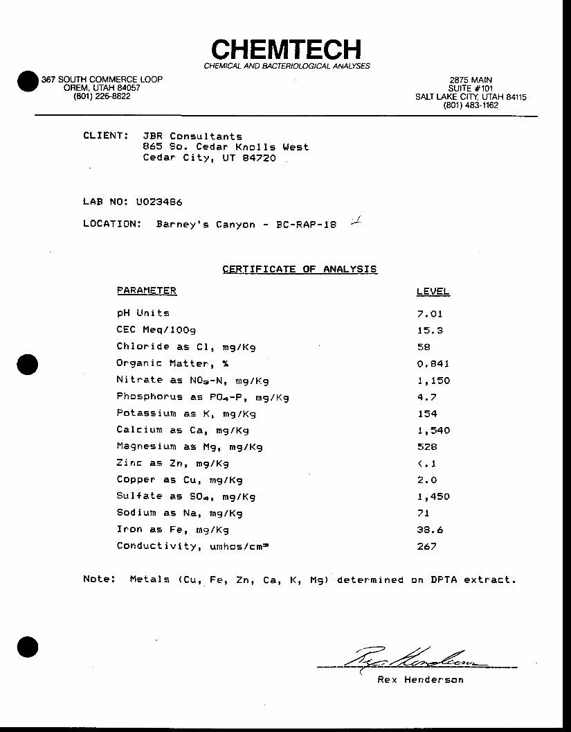
CHEMTECHCHE M ICAL AN O BACTER I O LOG I CAL ANALYSES
367 SOUTH COMMERCE LOOPOREM. UTAH 84057
(w1) 226-8822
2875 MA|NSUITE #101
SALT LAKE CITY UTAH 84115(801) 483-1162
CLIENT : JBR Consu l t an t s865 So . Ceda r Kno l l s Wes tCeda r C i t y , UT E47ZO
LAB NO: UO23486
L O C A T I O N : B a r h e y ' s C a n y o n - B C - R A P - t B /
CERTIFTCATE OF ANALYSIS
FARAHETER
p H U n i t s
C E C H e q / l O O 9
C h l o n i d e a s C l , m g / K g
O r . g a r r i c M a t t e r . , %
Ni t r .a te as NOs-N , mgtK.g
P h o s p l . f o r u s a s P O a - P , m g / R g
Potass iu t r r r as Kr mg/Kg
C a l c i u n a s C d , m g / K g
Hagnes ium as I ' tg , mg/Kg
Z i n c a s Z n , m g l K g
C o p p e r a s C u , m g / K g
S u l { a t e a s S O a r n g l K g
S o d i u m a . s N a , m g / K g
f r o n a s F e , m 9 / K g
C o n d u c t i v i t y , u r i l h o s / c m s
N o t e ! | ' l e t a l s ( C u , F e , Z n , C a , K , H g ) d e t e r . m i n e d
LEVEL
7 , O t
1 5 , 3
seo . 8 4 1
1 r 1 5 O
4 . 7
1 5 4
t r 3 4 O
52e( . 1
2 .O
1 , 45O7 t
38 .6
267
on DPTA ex t rac t .
Hender 'son

Fitzegerald
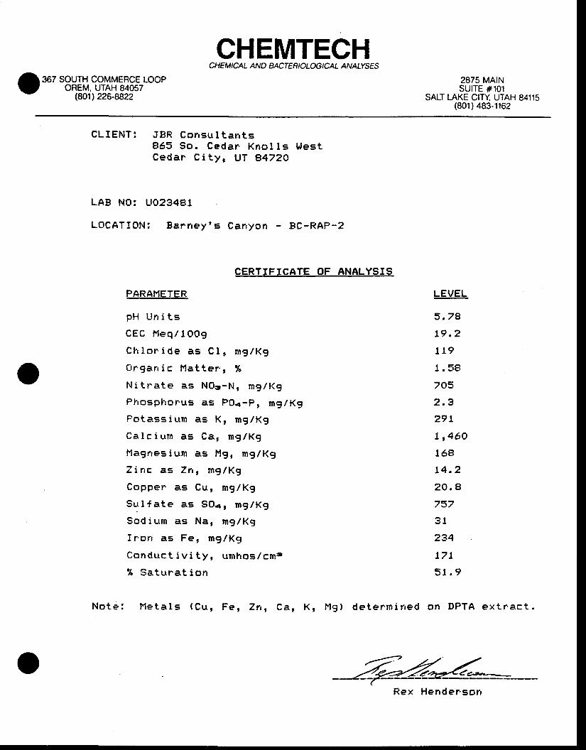
CHETT'ITECHCHEM I CAL AND BACTER I OLOG I CAL ANATYSES
367 SOUTH COMMERCE LOOPOREM. UTAH 84057
(8O1) 226-8822
2875 MAtNSUITE #101
SALT LAKE CITY UTAH 84115(801) 483-1162
CLIENT : JBR Consu I t an t s865 So . Cedar . Kno l l s h les tCedar C i t y , UT e47ZO
LAB NO: UO23481
LOCATICTN: Ba rney ' s Canyon - BC-RAP-2
CERTIFICATE OF ANALYSIS
PARANETER
pH Urr i ts
C E C H e q / 1 O O 9
C l i l o n i d e a s C I , m g l K g
C t r g a n i c I ' t a t t e r . , %
N i t r a t e a s N O g - N , m g l K g
P h o s p F f o r ' u s a s P O < - P , m g / K g
P o t a s s i l t m a s K , m g / K g
C a l c i u m a s C B , m g / K g
Hagrres i um as l , lg, mg / Kg
T i n c a s 7 n , m g l K g
C o p p e r a s C u , m g / K g
S u l { a t e a s S O a , m g / K g
S o d i u m a s N a , m g / K g
f r .o r r as Fe, mg lKg
C o n d u c t i v i t y , u n r h o s / c m e
% S a t u n a t i o n
LEVET
3.7e
19 .2
t 19
I . 59
705
2 ,3
29 t
I , 460
168
t4 .2
20 . 4
757
3 l
234
17 t
5 l . 9
No te : Me ta l s (Cu , Fe , 7n , Ca , K , Mg ) de te rm i r red on DPTA ex t r ' ac t .
Rex Hender ' son
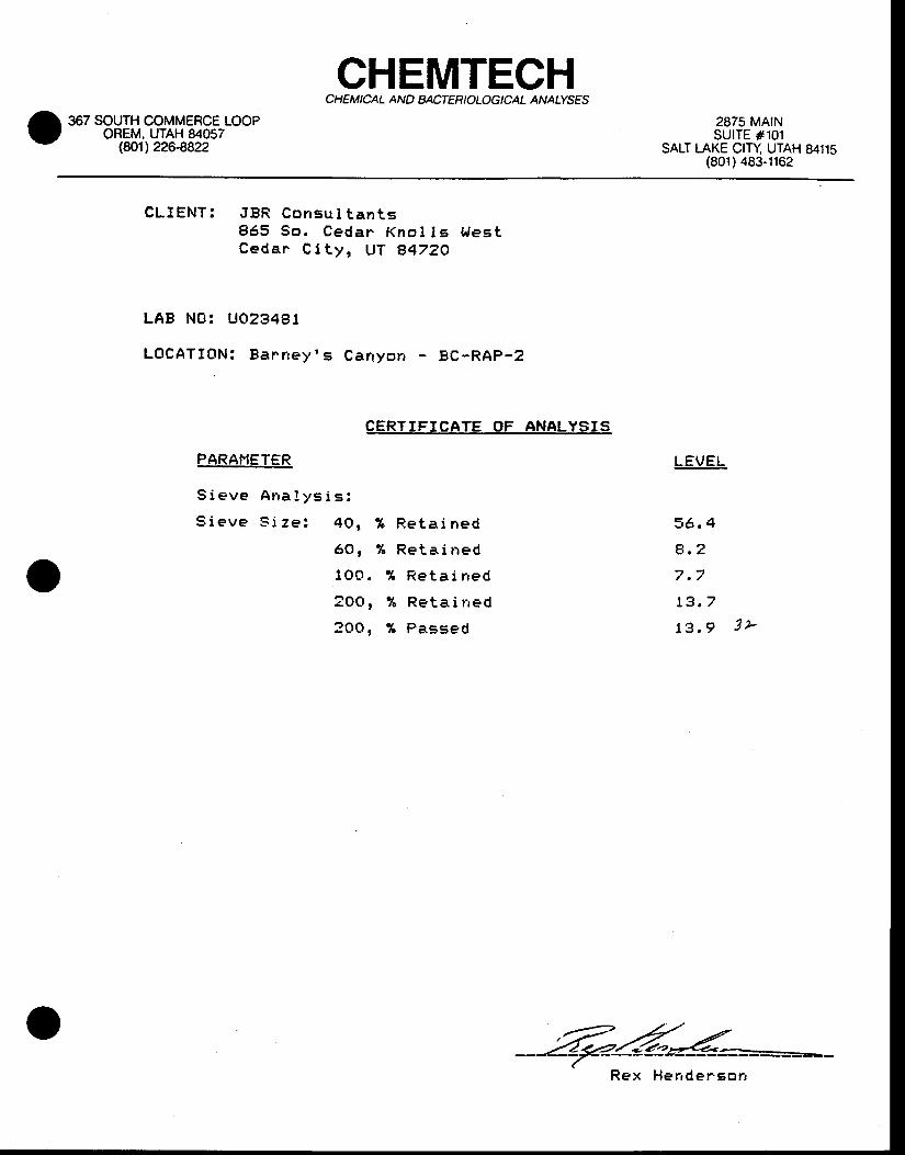
CHEMTECHCHEM ICAL AN D BACTER I OLOG I CAL ANATYSES
367 SOUTH COMMERCE LOOPOREM, UTAH 84057
(8O1) 226-8822
2875 MAINSUITE #101
SALT [-AKE C|TY UTAH 84115(801) 483-1162
CLIENT : JBR Consu l t an t s865 5o . Cedar Kno I l s t r l es tCeda r C i t y , UT A4ZZO
LAB NO: UO234ST
LOCATION: Banney ' s Car ryo r r - BC-RAp-z
CERTIFICATE OF ANALYSIS
PARAI"IETER
S i e v e A r r a l y s i s :
S i e v e S i z e : 4 0 , % R e t a i n e d
6 0 , % R e t a i n e d
l O O . % R e t a i n e d
2 O O , % R e t a i r r e d
? O O , % P a s s e d
LEVEL
36 .4
4 ,2
7 .7
t3 .7
13 ,9 3 ,
4tuR e x H e n d e r s o r r
Copperton
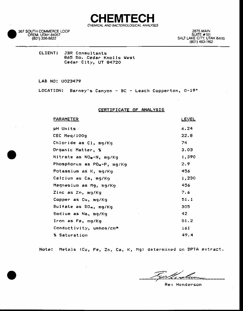
CHEMTECHC HEM ICAL AND BACTER I OLOG I CAL ANATTSES
367 SOUTH COMMERCE LOOPOREM. UTAH 84057
(801122c.8822
2875 MAINSUITE #101
SALT IAKE CITY UTAH 84115(801) 483-1162
CLIENT : JBR Consu l t an t s865 5o . Ceda r Kno I l s L fes tCeda r C i t y , UT e472O
LAB NOi VO23479
LOCATION: Ba rney ' s C a n y o n - B C - L e a c h C o p p e r ' t o n r O - 1 9 '
CERTIFICATE OF ANALYSIS
PARAI'IETER
pH Un i t s
CEC l l eq / lOOg
Ch lo r . i de as C l , mg /Kg
Or .gan i c Ha t t e r , %
N i t r a te as NO= , -N , mg lKg
P l rosp l i o rus as POa-P , ng /Kg
Pote,ss i u t rn as K, mg/Kg
Ca l c i l tm as Ca , mg /Kg
l ' lagnesium as I ' lg , mg/Kg
Z inc as 7n , mg /Kg
Coppen as Cu , mg /Kg
9u l {a te as SOor mg /Kg
Sod ium e .s NB, m9 /K9
I ron as Fe , mg /Kg
Conduc t i v i t y , umhos I cm?
% Sa tn ra t i on
N o t e : N e t a l s ( C u , F e , Z n , C a , K , M g ) d e t e r ' r n i n e d
Ll:VEL
6 .24
22 . 4
74
3 . 03
1 , 390
2 .9
456
1 r23O
456
7 .6
51 . I
305
42
e t . 2
te t
49 . 4
cn DPTA ex t r ' ac t ,
R e : < H e n d e r . s o n
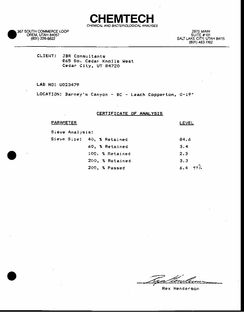
CHEMTECHCHEM ICAL AND BACTER IOLOG ICAL ANALYSES
367 SOUTH COMMERCE LOOPOREM, UTAH 84057
(eol') 226-8822
2875 MAINSUITE #101
SALT I-AKE CITY UTAH 84115(801) 483-1162
CLIE I {T : JBR Consu l t an tsP65 So , Ceda r ' Kno l l s Wes tCedan C i t y , UT B4ZZO
LAB NOi UO23479
LOCATION: gaFne :v ' s Ca r r yon - BC - Leach Coppe r ton , O -19 '
CERTIFICATE OF ANALYSIS
PARAMETER
S i e v e A n a l y s i s :
S i e v e S i z e : 4 0 ,
LEVEL
84 , 6
3 .4a 't-
3 .3o :
6 .4 4a [ ,
6 0 t
100 ,
?oo,2 O O ,
% R e t a i n e d
% R e t a i r r e d
% R e t a i r r e C
% R e t a . i n e d
% P a s s e C
Rex Hender 'sorr
Bradhsaw-Agassiz
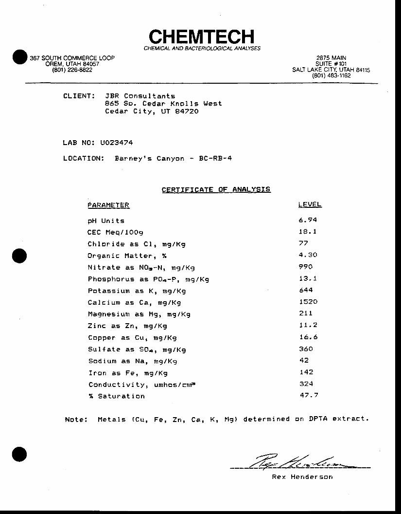
CHEMTECHCHEM ICAL AN D BACTER IOLOG I CAL ANAIYSES
367 SOUTH COMMERCE LOOPOREM. UTAH 84057
(8O1) 226-8822
2875 MA|NSUITE #101
SALT LAKE CITY UTAH 84115(801) 483-1162
CLIENT : JBR ConEu l t an t s865 So . Ceda r Kno l l s h l es tCedar C i t y , UT 84720
LAB NO: UO23474
LOCATION! Ba r ' ney ' s Carryon BC-RB-4
CERTIFICATE OF ANALYSIS
FARAI"IETER
p H U n i t s
CEC F leq / 1Oo9
C l i l o r . i d e a . s C l , m g / K g
O r g a n i c H a t t e r , %
N i t r a t e a s N O g - t ' | , m g / K g
P h o s p l r o r u s a s P O a - P , m g / K g
P o t a s s i u m a s K , m g / K g
C a l c i u r n a s C a , n g / K g
H a g n e s i u m a s l ' , 1 9 , m g / K g
Z i n c a s Z n , m g / K g
C o p p e r a s C u , m g / K g
S u l f a t e a s S O a r m g / K g
S o d i u r n a s N a , n g l K g
f r ' o n a s F e l m g / K g
C 6 n d u c t i v i t y , u m h o s l c r r r s
% Satura t i o r r
LEVEL
6 . 9 4
1 9 . 1
7 7
4 , 3 0
9 9 0
1 3 . 1
644
1 5 ? O
z tL
17 .?
t6 .6
360
42
14"
324
47 .7
N o t e : I 1 e t a l s ( C u , F e , Z n , C a , K , l ' t g l d e t e r m i r r e d o n D P T A e x t r ' a c t .
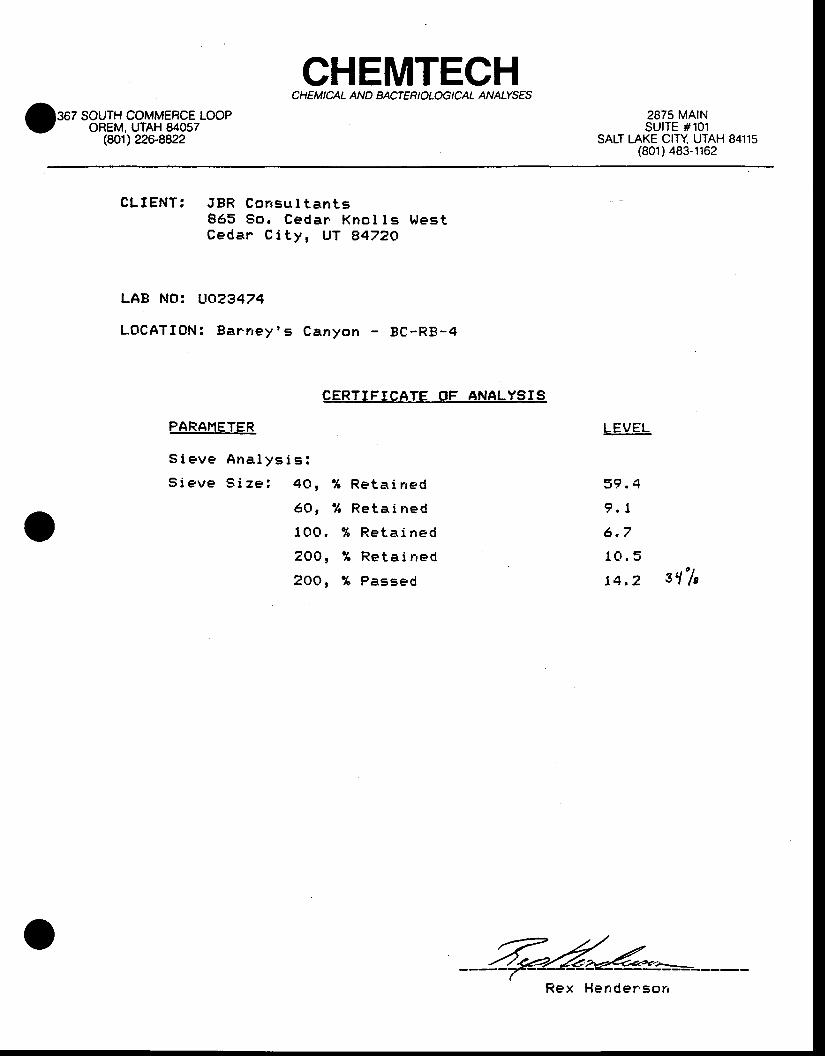
CHEMTECHC HEM I CAL AN D BACTER I OLOG I CAL ANAIYSES
367 SOUTH COMMEBCE LOOPOREM, UTAH 84057
(eol) 226-8822
2875 MAINSUITE #101
SALT LAKE CITY UTAH 84115(801) 483-1162
CLIENT : JBR Consu l t an t s865 So . Cedar Kno l l s Wes tCeda r C i t y , UT A472O
LAB NOr UO23474
LOCATION! Ba r r rey ' s Canyon BC-RB-4
CERTIFICATE gF ANALYSIS
PARAHETER
S i e v e A n a l y s i s :
S i e v e S i z e : 4 0 , % R e t a i n e d
6 O , % R e t a i n e d
1 O O . % R e t a i n e d
Z O O , % R e t a i n e d
2 O O , % P a s s e d
L E V E L
5 9 . 4
9 , 1
6 , 7
1 0 . 5
t4.z 3 ' l ' /e
Rex Hender ' son
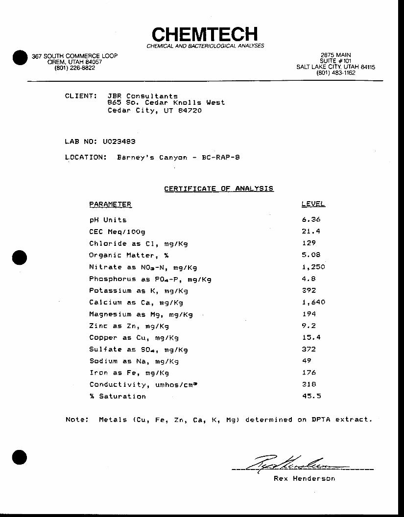
CHEMTECHCHEM ICAL ANO BACTER I OLOG I CAL ANAIYS€S
367 SOUTH COMMERCE LOOPOREM, UTAH 84057
(8O1) 226-8822
2875 MArNSUITE #101
SALT LAKE CITI 9146 3A11U(801) 483-1162
CLIENT : JBR Consu l t an t s865 So . Cedar Kno l l s t r l es tCedan C i t y , UT A472O
LAB NO: UO23483
LOCATION: Ba rney ' s Canyor r - BC-RAP-B
CERTTFICATE OF ANALYSIS
PARAHETER
p H U n i t s
C E C F l e q / l O A g
C h l o n i d e a s C l , r n g / K g
O r g a n i c H a t t e r , %
N i t n a t e a s N O 3 - N , m g / K g
P l . r o s p h o r u s a s P O a - P , m g / K g
P o t a s s i u m a s K , m g / K g
C a l c i u m a s C a , m g / K g
Hagnes ium as f r , lg , mg/Kg
T i n c a s Z n , m g / K g
C o p p e n a s C u , m g / K g
9 u l { a t e a E S O e r m g / K g
S o d i l t m a s N a , m g / K g
f r ' o r r a s F e , m g l K g
C o n d u c t i v i t y , u n h o s / c m s
% S a t u n a t i o n
N o t e : N e t a l s ( C u , F e , Z n , C a , K , H g ) d e t e r m i r r e d
LEVEL
6 . 3 6
2 t . 4
129
5 . 0 8
1 r 2 5 O
4 , 8
?92
1 r 6 4 O
1 9 4
9 . 2
1 5 . 4
372
4 9
1 7 6
? 1 8
4 5 . 5
o r r D P T A e x t r ' a c t .
R e x H e n d e r E o n
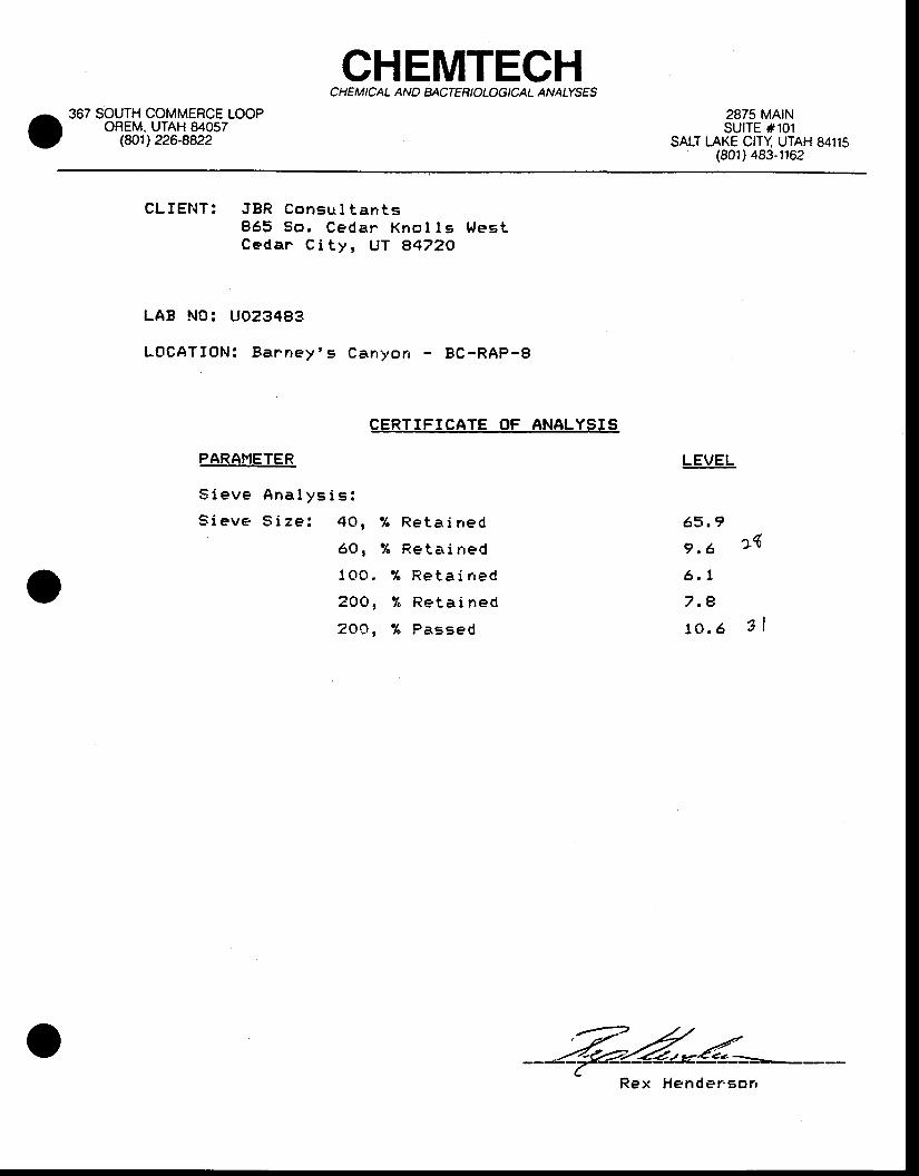
CHEMTECHCHE M I CAL AND BACTER I OLOG I CAL ANATYSES
367 SOTJTH COMMERCE LOOPOREM, UTAH 84057
(8O1) 226-e822
2875 MAINSUITE #101
SALT t AKE CrTl g14g 3a1t,(801) 483-1162
CLIENT : JBR Consu l t an t s865 So . Cedar Kno l I s l Jes tCeda r C i t y , UT A472O
LAB NO: UO23483
LOCATIC IN : Ba r r rey ' s canyon - Bc -RAp-8
gERTIFICATE OF ANALYSIS
PARAFIETER
S i e v e A n a l y s i s :
S i e v e S i z e : 4 0 , % R e t a i n e d
6 O , % R e t a i n e d
1 O O . % R e t a i n e d
2 O O , % R e t a i n e d
2 O O , % P a E s e d
LEVEL
6 5 . 9
9 . 6
6 , 1
7.e10 .6
"4
3l
Rex Hender 'sorr
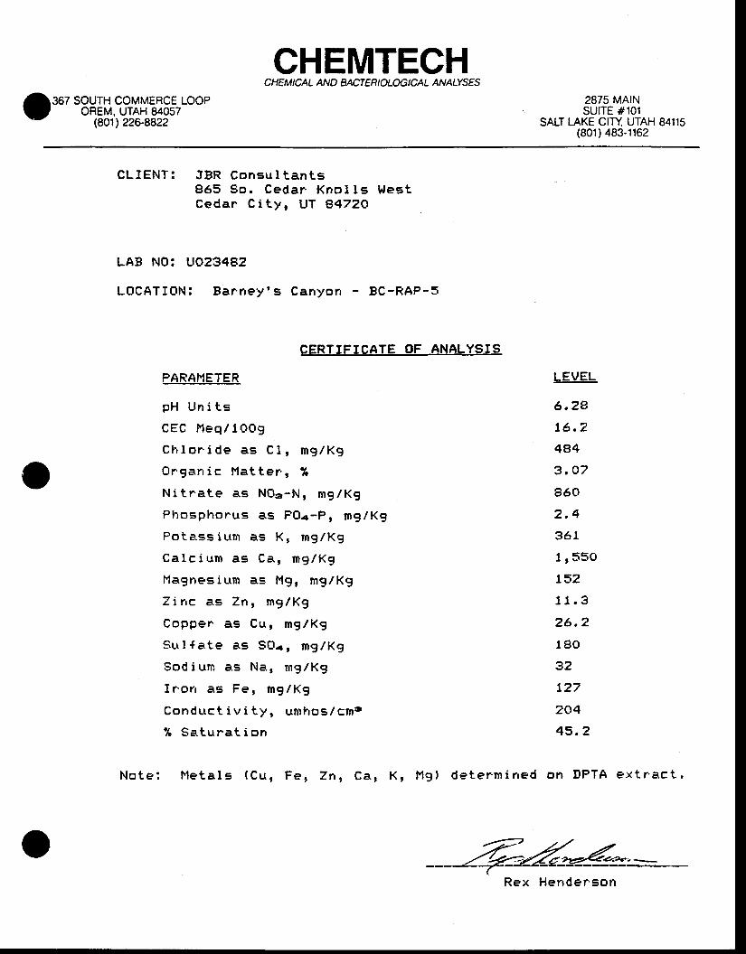
CHEMTECHCHEM ICAL AND BACTER I OLOG ICAL ANAIYSES
367 SOUTH COMMERCE LOOPOREM. UTAH 84057
(801) 226-8822
2875 MAINsulTE #101
SALT I-AKE CITY UTAH 84115(801) 483-1162
CLIENT : JBR Consu l t an t s865 $o . Ceda r Kno l l s t l es tCedan C i t y , UT A472O
LAB NO: UO234g2
LOCATIBN: Ba rney ' s Canyon - BC-RAP-S
CERTIFICATE OF ANALYSIS
PARAHETER
p H U n i t s
C E C F l e q / l O O 9
C h l o r i d e a s C 1 , m g / K g
O r g a n i c M a t t e r . , %
N i t r a t e a s N 0 a - N , m g / K g
P l r o s p h o n u s a s P O a - P , m g / K g
P o t e . s s i u t m a s K , m g / K g
C a 1 c i u m a E C a , n g / K g
Magnes ium as l , tg , mg/Kg
Z i n c a E Z n , m g / K g
C o p p e r a s C u , m g / K g
S u l { a t e a s S O a r m g / K g
S o d i u n a s N a , m g / K g
I r ' o n a s F e , m g / K g
C o n d u c t i v i t y , u m h o s / c m t
% S a t u r a t i o n
N o t e : H e t a l s ( C u , F e , Z n , C a , K , H g ) d e t e r ' m i n e d
LEVEL
6 .24
t6 .2
4e4
3 .07
860
2 .4
361
1 r550
152
11 .3
26 .2
180
32
t27
2c|4
43 .2
on DPTA ex t r ' ac t ,
Rex Herrder 'son
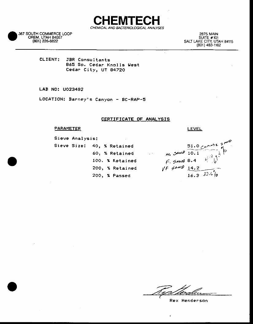
CHEMTECHCHEM ICAL AND BrcTERIOLOG ICAL ANATYS€S
367 SOUTH COMMERCE LOOPOREM, UTAH 84057
(80',t) 226.8822
2875 MAINSUITE #101
SALT LAKE CIry UTAH 84115(801) 483-1162
CLIENT : JBR Consu l t an t s865 So , Cedar Kno I I s l r l es tCeda r C i t y , UT B4ZZO
LAB NO: UO23482
LOCATIONT Ba rney ' s Canyon BC-RAP-5
CERTIFICATE OF ANALYSIS
PARAFIETER
S i e v e A n a l y s i s :
S i e v e S i z e : 4 0 , % R e t a i n e d
6 0 , % R e t a i n e d
1 O O , % F , e t a i n e d
2 O O , % R e t a i n e d
2 O O , % P a s s e d
M' ' i *J0
€'1*n'o/ f ttto
LEVEL
51 .O /o^ * i ' 2 r / '---'- --- -' '-* - - ln10. I , : , \ "
, . . i I ^ ,
8 .4 ^ : 6 i
!3:3---o.--16.3 33 'c 1 ,
Rex Hender ' son

CHEMTECHCHEM ICAL AND BACTER I OLOG I CAL ANAIYSFS
367 SOUTH COMMERCE LOOPOREM, UTAH 84057
(8011226-8822
2875 MAtNSUITE #101
SALT I-AKE CITY UTAH 84115(801) 483-1162
CLIENT: JBR Cor rsu l t an ts865 So . Cedar Kno l l s l , t es tCedar * C i t y , UT A47ZO
LAB NO. LtO23476
LOCATION: Ba r .ney ' s Canyon - BC-RB-9
CERTIFICATE OF ANALYSIS
PARAF,IETER
pH Un i t s
CEG Heq /14O9
C l r l o r i de as C l , mg /Kg
Or .gan ic l ' l a t t e r , %
Ni tna te as l . l 0o -N , mg /Kg
PFrosphorus as PO. r -P , mg lRg
Po tass ium as Ke mg /Kg
Ca lc i un as Ca , r ng /Kg
l ' l agnes ium as Mg , mg /Kg
Z inc as 7n , mg /Kg
Copper as Cu , mg /Kg
Su l {a te as SOar mg lKg
Sod ium as Na , mg /Kg
I r ' on as Fe , mg /Kg
Conduc t i v i t y , umhos . / cng
% Satunat i or r
N o t e : F l e t a l s ( C u , F e , Z n , C a , K , H g l d e t e r m i n e d
LEVEL
6 . 1 5
2 5 , 6
244
1 . 9 1
I r l 4 0
4 . 1
356
1 r 8 3 O
I r g 6 0
9 . 6
23. 6
389
4 1
1 7 6
2= t
50 . 3
on DPTA ex t r . ac t .
Rex Her rde rson
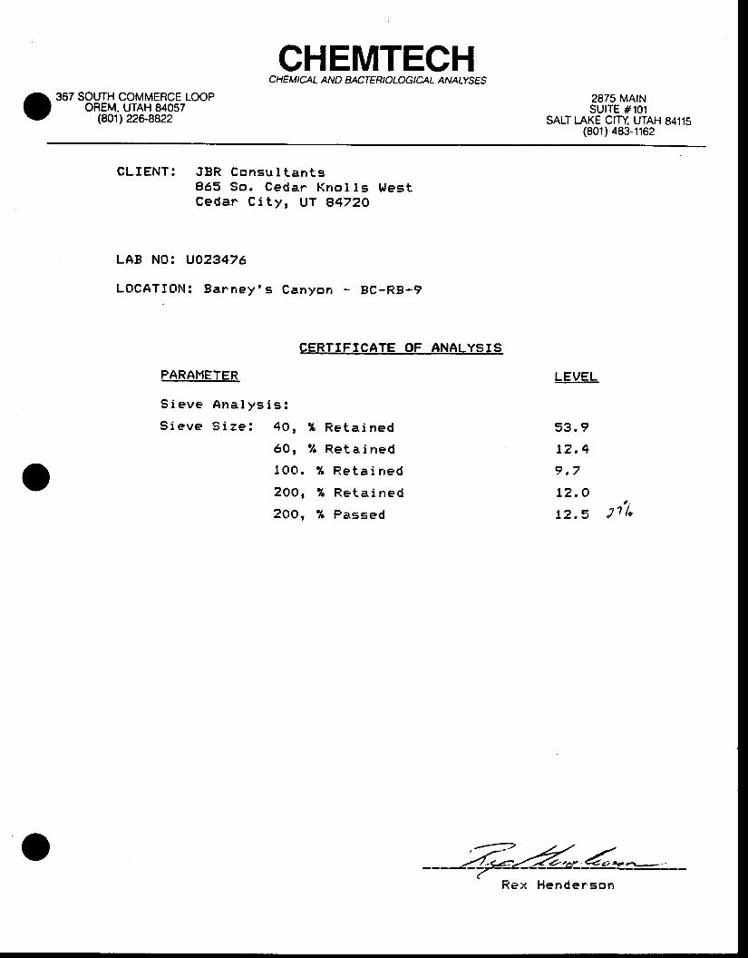
CHEMTECHCHEMICAL AND BACTERIOLOG ICAL ANAIYSES
367 SOUTH COMMERCE LOOPOREM. UTAH 84057
(801) 226-8822
2875 MA|NSUITE #101
SAUT LAKE CITY UTAH 84115(801) 483-1162
CLIENT : JBR Consu l t an t s865 So , Ceda r Kno l l s Wes tCeda r C i t y , UT g47ZO
LAB NOi UO23476
LOCATIONT Ba rney ' s C a n y o n - B C - R B - 9
CERTIFICATE OF ANALYSIS
PARAI.lETER
S i e v e A n a l y s i s :
S i e v e S i z e : 4 0 , % R e t a i n e d
6 O , % R e t a i n e d
1 O O , 9 6 R e t a i n e d
2 0 O , % R e t a i n e d
2 O O , % P a s E e d
LEVEL
53 . I
t 2 . 4
9 .7
t2 . ot t
1 2 , 5 J l l o
Hender 'son

Gappnayer-tfal lsburg
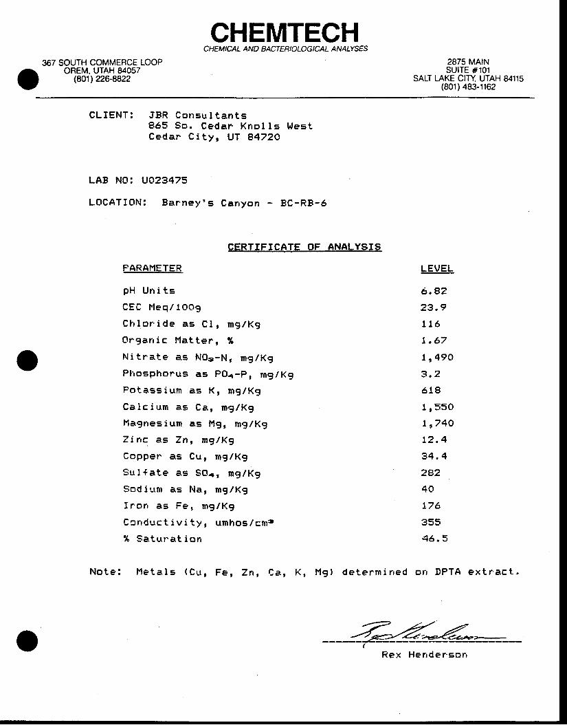
CHEMTECHCHEMICAL AND EACT ER I OLOG I CAL ANATYSES
367 SOUTH COMMERCE LOOPOREM. UTAH 84057
($O1) 226-8822
2875 MA|NSUITE #101
SALT LAKE CITY UTAH 84115(801) 483-1162
CLIENT : JBR Consu l t an t s865 So . Ceda r Kno l l s Wes tCedan C i t y , UT A47ZO
LAB NO: UO23475
LOCATION: Ba r .ney ' s Canyon - 8C-RB-6
CERTTFICATE OF ANALYSIS
FARAFIETER
p H U n i t s
C E C H e q / l O O g
C h l o r ' i d e a s C l , m g / K g
O r g a n i c H a t t e r , %
N i t r a t - e a s N O ' - N ; r n g / K g
Pl ' fosphorus as POa-P, rng lKg
P o t a s s i u m a s K , m g / K g
C a 1 c i u m a s C a , n g l K g
M a g n e s i u m a s l ' l g , m g / R g
7 i n c . a s Z n , n g / K g
C o p p e r a s C u , r n g / K g
S u l f a t e a s S G e r m g / K g
S o d i l t m a s N a , m g / K g
f r ' o n a s F e , m g l l t g
C c n d u c t i v i t y , u n h o s / c n s
% S a t u n a t i o n
N o t e : I ' l e t a l s ( C l t , F e , Z n , C a , K , l . 1 g ) d e t e r m i r r e d
LEVEL
6 . a2
23 .9
116
r .67
1 r49O
3 .2
618
1 r55O
L r74O
12 .4
34 .4
2P2
40
176
355q6 . 5
orr DPTA ex t r 'ac t .
R e x H e n d e r ' E o n
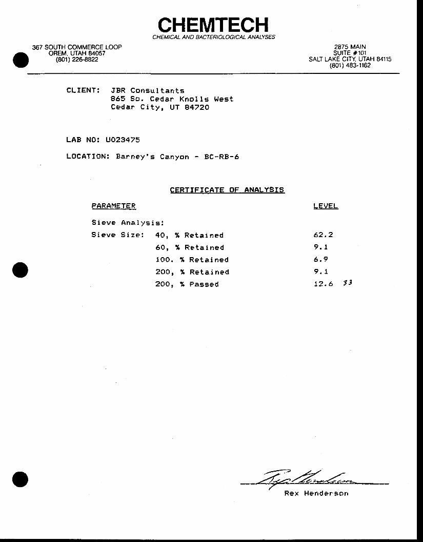
CHEMTECHCHEMICAL AND BACTERI OLOG ICAL ANATYSES
367 SOUTH COMMERCE LOOPOREM, UTAH 84057
(8O1) 226{,822
2875 MAINSUITE #101
SALT LAKE CITY UTAH 84115(801) 483-1162
CLIENT : JBR Consu l t an t s865 So . Cedar Kno l l s t , l es tCeda r C i t y , UT A472O
LAB NO'. UO23473
LOCATION: Ba rney ' s Canyon BC-RB-6
CERTIFICATE OF ANALYSIS
PARANETER
9 ieve Ana l ys i s :
S ieve S i ze : 40 ,
6o t
100 .
200 ,
zOQ,
% R e t a i n e d
t R e t a i n e d
? t R e t a i n e d
I R e t a i n e d
% Passed
LEVEL
62 .2
9 .1
6 .9
9 ,7
12 .6 1t
Rex Her rder 'son
APFENDIXGIII
AqD/BASE POTE{IIAL IABOR.AT{)RY REFORTIS
u}5
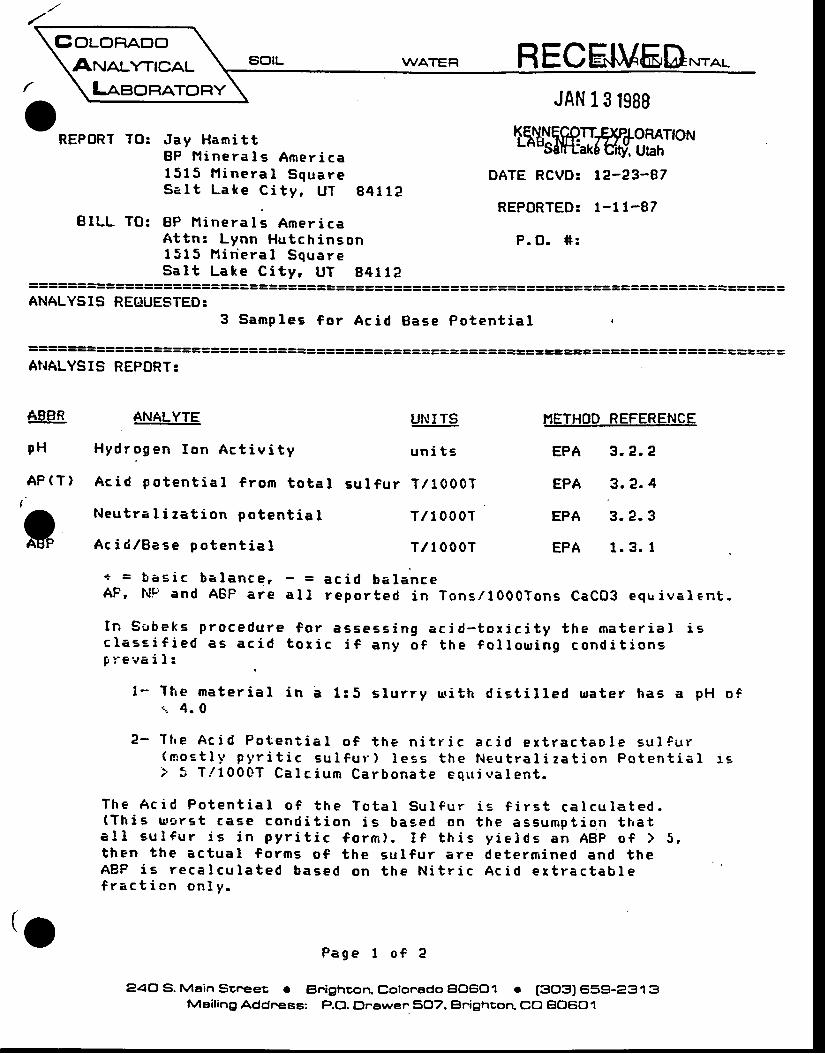
GolonAooAruaunrcAL
LasonAToRYRECE.IU6D
oREPORT TO: Jay Hami t t
BP l ' l i ne ra l s Amer i ca1513 l ' l i ne ra l Squa reSa l t La le C i t y , UT g4 t1e
BILL TO: BP I ' l inera I s Amer i caA t t n : Lynn Hu tch inson1515 l ' t i r i e ra l Squa reSa l t Lake C i t y , UT g4 l lA
======================================================================= =====: =ANALYSIS REGUESTED:
3 Samp les f o r Ac id Base Po ten t i a t r
DATE RCVD: t2-23-87
REPORTED: l -1 t -87
P .O . * :
================================
AT{ALYSIS REPBRT:
ABBR
pH
AP(T}
ANALYTE
Hyd rogen I on Ac t i v i t y
Ac id po ten t i a l f r om to ta t
t l eu t ra I i za t i on po ten t i a I
UI{ITS
un i t s
su l f u r T /10007
T /10007
T / I 0007
''IETHOD REFERENCE
EPA 3 . e .2
EPA 3 .2 .4
EPA 3 . e .3
EPA 1 .3 . I; Ac i d lBase po ten t i e l
+ = t r as i c ba lance ,AF, l t t r ' and ABP are
In Sgbeks p rocedu rec lase i f i ed as ac idg reva i I :
t - The rna te r i a l i n ar . 4 .0
1 :5 s l u r r y r r r i t h d i s t i l l ed ua te r has a pH s f
2 - The Ac id Po ten t i a l o f t he n i t r i c ac i d ex t rac tao le eu l f u r(mo : t l y py r i t i c su l f u r ' ) l e ss t he l l eu t ra l i za t i on Po ten t i a l i si ' 3 f / 1000T Ca l c i um Ca rbona te eq r r i va l en t .
The Ac id Po ten t i a l o f t he To ta l su l f u r i e f i r s t ca l cu la ted .(Th i s L r s r s t caEe cond i t i on i s based on t he assump t i on t ha ta !1 su l f u r i s i n py r i t i c f o rm) . I f t h i s y i e l ds an ABp o f > S ,t hen t he ac tua l f o rms o f t he su l f u r a re de te rm ined and t heABP i s r eca l cu la ted based on t he N i t r i c Ac i d e r t r ac tab lef r ac t i on on l y -
Page 1 o f 2
eao S. Mein Scr.eet . Elnighcon. Cotonado BO6OI e [3O3J 659-231 3Meiling Addr.ess: P.O. Dnewer5,OT. Elnighcorl CO El(]60'l
- = ac i d ba lancea l l r epo r ted i n Tons /1000Tons CaCO3 equ i va len t .
f o r asse : s i ng ac id - t ox i c i t y t he ma te r i a l i st o r i c i f any o f t he f o l l o r r r i ng cond i t i ons
tj
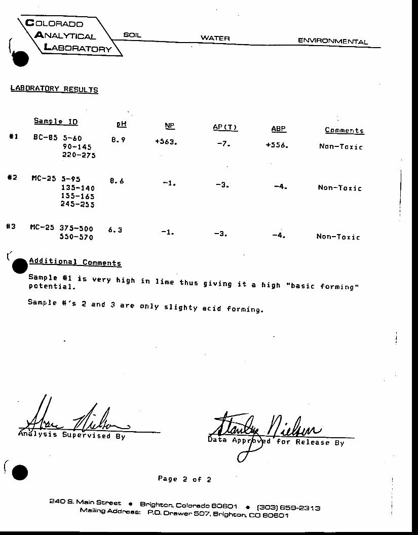
EouoRp.ooAnJauntcAL SOIL
( . \
t.^ \LaeoRATonyI
sld
8 .9
Ne.+563 .
AP (T )
-7.
*2
s3
[ iaoo i t ionar co*e. ts
Samp le *1 i spo ten t i a l .
Samp le * , s e
{1p a g e e o f ?
44., s' Mein srr-er . Bnighron coronedo .,0601 . t3031659-2313Meiling Addr.eee: p.O. Dnerryen5O7. BFighcorr. CO Et06C)I
LABORATORY RESULTS
Samole IO
8C-85 5-6090_1452a0-275
t'tc-2S 5-951 35_140I 55_ t 65?45_e55
f. tc-25 375-500550-570
8 .6 -1 . -3 .
6 .3
ve ry h i gh i n l ime t hus
and 3 a re on l y s l i gh t y
\^/ATER
-4.
-4.
g i v i ng i t a h i gh
ac id f o rm ing .
ABP
+556 .
ENVIRc)NMENTAL
Cornmen t s
Non-To r i c
Non-To r i c
Non-To x i c
"bas i c f o rn i i ng . ,
I y s i s Sup e l v i sed ta App Re lease By
APFEhIDD(I).I
OPERAIIO}.IAL IMFOTJNDMH{r SrAGE CAPACIIY CI,'RVES
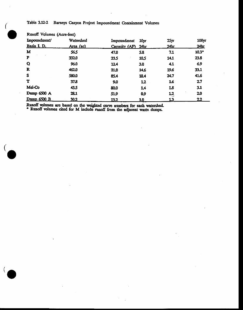
Tablc 3.XL-2 Bameys Canyon Projcct Imponndmcnt Containmcnt Volumcs
Runofr Volumcs (Acre.fect)
ImpouadnrcnU WatcrshcdBasi! L D. Arca (ac)
Impormdmcnt l0Jrr 25yrCanacitv (AF) z}hr ?l'hr
100yr2Ahr
MP
oRsTMcl€o
qnB5xL42L085.49J
800519
5a1053014.61&4t2L409
7J,14J4t
19.62A:7lsL8
103.a86.9
B,L415IT3.1
565&096.0
46'2JJsgtof la435
DuEp 6fln A AlDumo 6$0 B n2
yL 20132 LO ljl 22
RunoE rclumcs !rc bascd on thc creicttcd cnrtc aumbcc for cach watcEshcd.' RunoE volumes citcd for M indudc-ruaoff from thc adjaccot wastc duraps
(IO
'o
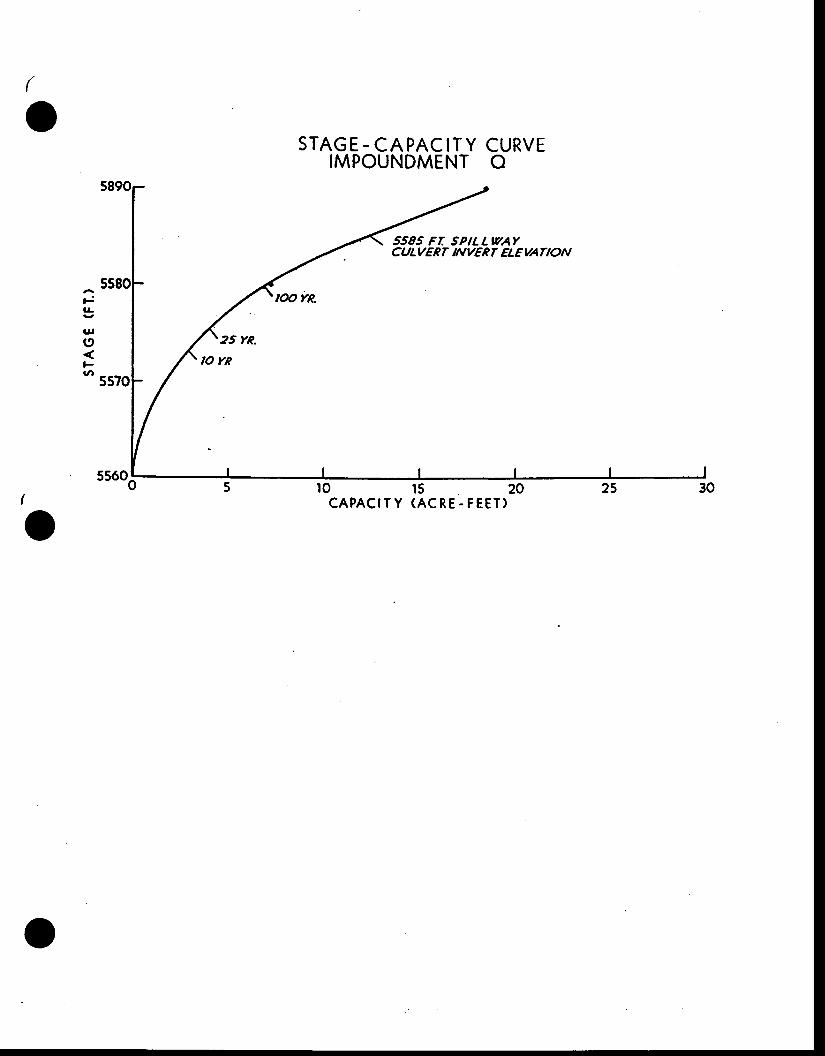
(
oSTAGE.CAPACITY CURVE
IMPOUNDMENT O
5585 FT SPILLIVAYCULVERT NVERT ELEUANON
Fl!
gl
I
g,
{
OCAPACITY (ACRE.FEET)
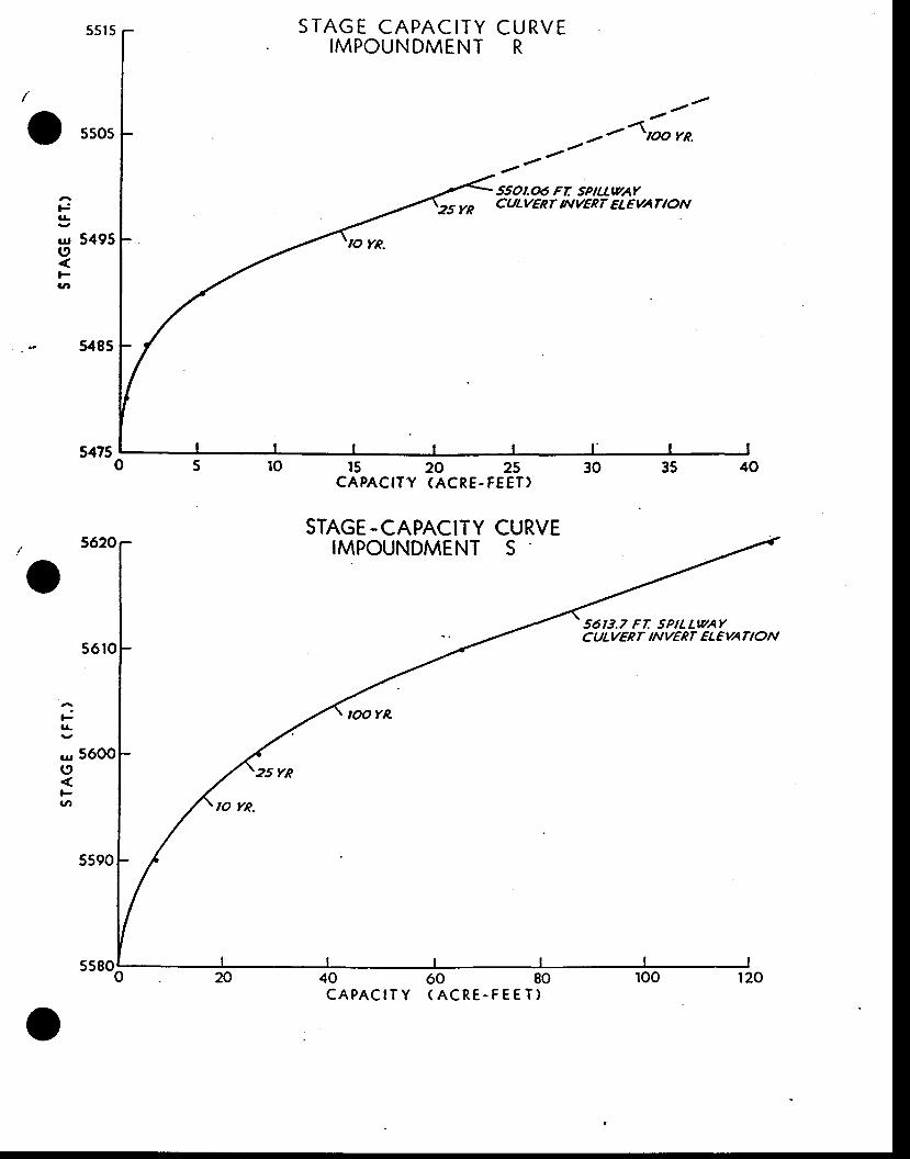
^rt
55r 5
5505
5495
FG
ur 5600(9
v,
S TAG E CAPAC ITYIMPOUNDMENT
CURVER
- /
--4po rn.. - /'''
550r.06 Fr sPtuvArCULUERT NVERT ELEUANONts
tL
|rII
vl
ss8o5
ro 15 20 25 30CAPACITY (ACRE.FEET)
STAGE -CAPACITY CURVEIMPOUNDMENT S
40 60 80CAPACITY (ACRE-FEET)
56t3.7 Fr SPTLLwAYC ULVER T N VER T EL E VATI ON
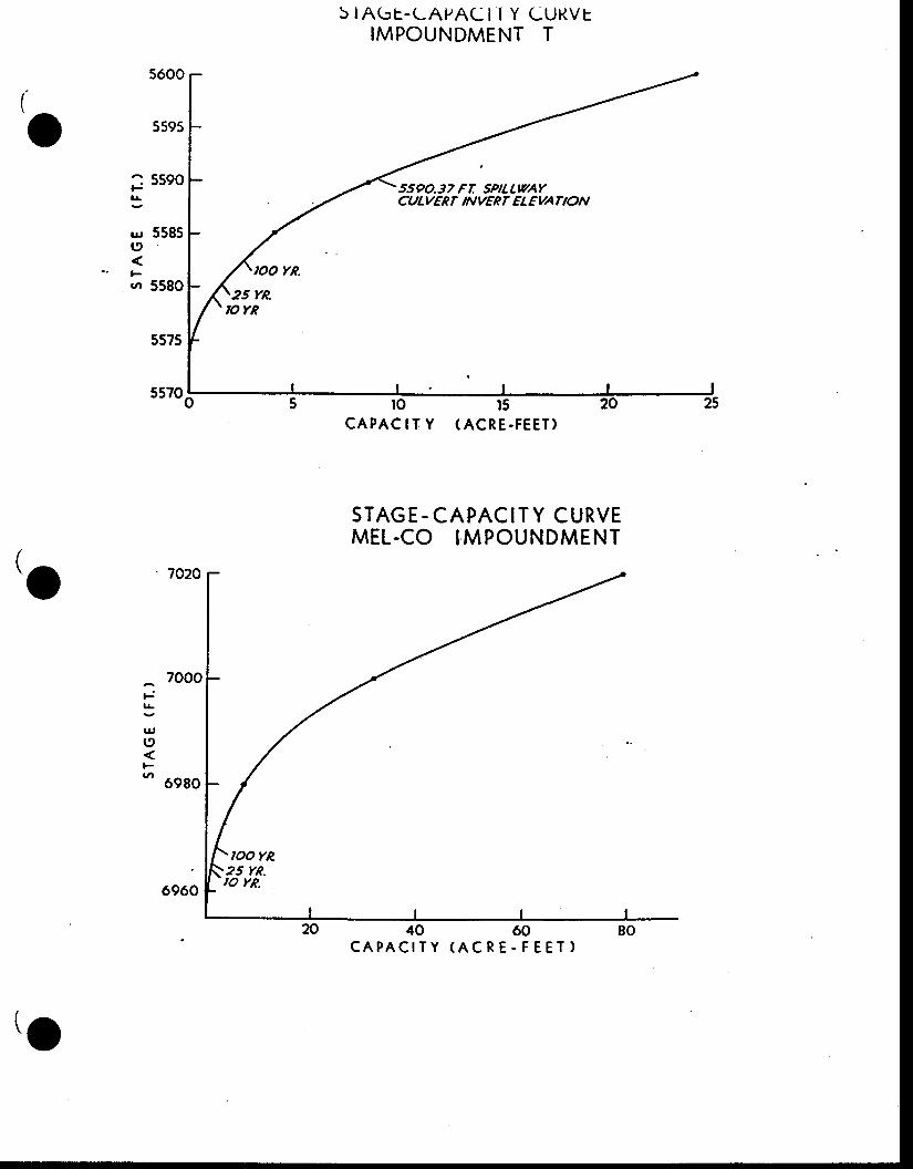
(I' ^ - ,
-
5600
5595
5590
558s
5580,OO YR.
5IAbL.LAPACI I Y CURVTIMPOUNDMENT T
--
5500.37 FT SPILL\TAYCULVERT NVERT ELEVANON
ro 15CAPAC IT Y (ACRE-FEET)
STAGE-CAPACITY CURVEMEL.CO IMPOUNDMENT
40 60CAPACITY (ACRE.FEET)
Ft!
g,
('
.tl
(.O
6960
25 YR.,orR
,OOYR.25 YR.,o rR.
F
u,19
Fv,
\O
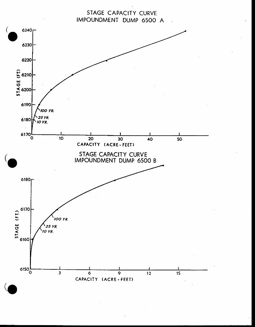
62Fl!
u,(9
Fv,
STAGE CAPACITY CURVEIMPOUNDMENT DUMP 6500 A
CAPACITY (ACRE - FEET)
STAGE CAPACITY CURVEIMPOUNDMENT DUMP 6500 B
6 9
C A P A C I T Y ( A C R E . F E E T )
6170
6r50;
o
(o
^6 'F
3u,c
-6r
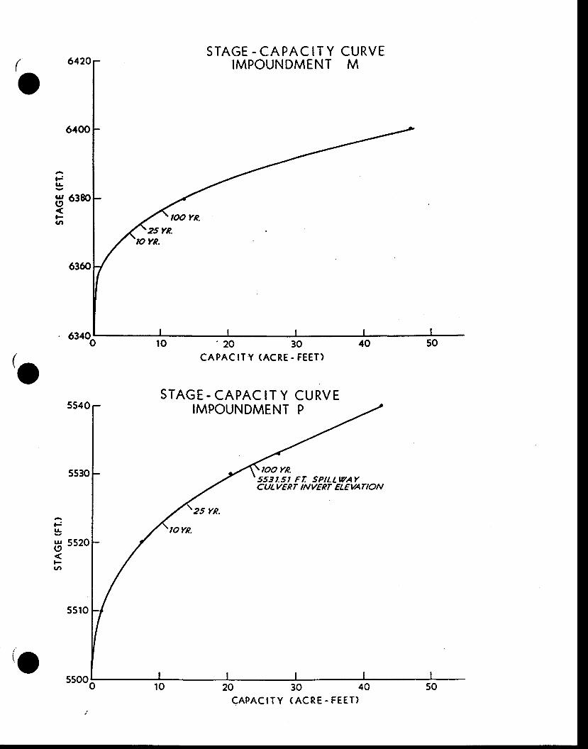
STAGE - CAPACITY CURVEIMPOUNDMENT M(
o
,o
t-l!
!{ 6380s,,
vr
' 20 30CAPACITY (ACRE. FEET)
STAGE - CAPAC IT Y CURVEIMPOUNDMENT P
553t.5t FT SPtLLtvAYCULVERT NVERT ELEVATION
20 30CAPACITY (ACRE.FEET)
F
|rI(oFVr
(ossoo6
ATPENDIX l>tr
DESTGN sPtsclrlcJrfllol{ls FoR clIANNErs AI.ID ROADSIDE DrrGrEs
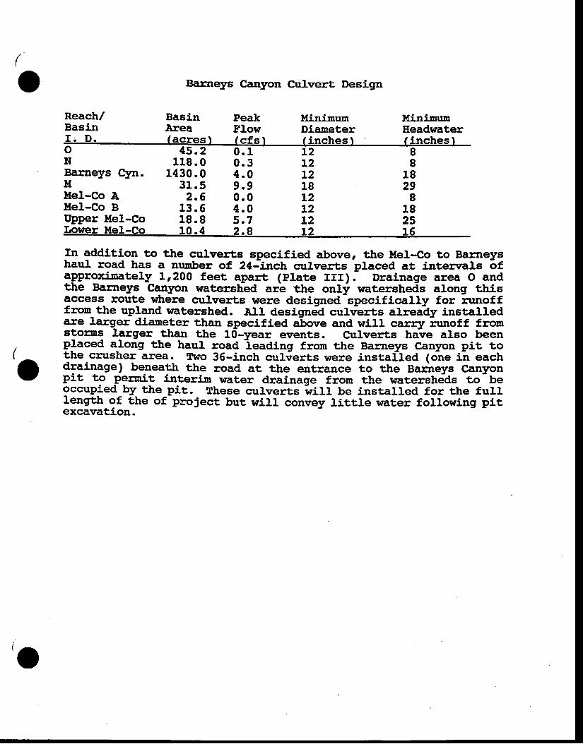
(
v Barneys Canyon Culver:t Design
Reach/Basin
BasinArea
PeakFlowf r : f s l
llinimunDianeter/ i nrrhaq I
llininunEeadrsaterI i nnhas If . D . f ae res l
Barneys Clm. 1430.0
88
1829
8182516
L2L2L218L2L2L2L2
oN
45.2119 .0
0.10.34.09.90.04.05.72.8
utfel-Co At{el-Co BUpper Mel-Co
31.52.6
13.518.9
Lower Mel-Co 10.4
(-v
Xn addition to ttre culverts specified above, the tIel-Co to Barneyshaul road has a number of, 24-inch culverts placed at interrrals ofapproximately 11200 feet apart (Plate rrr).- DraLnage area o andthe Barneys Canyon watershed arb ttre on{ rvatersheds along ttrisaccess route where culverts were designed specifically for nurofffrom_the upland watershed. All designed culvLrts alreaEy installedare larger dianeter than specified above and wirl cararz nrnoff froms9orns lerger than ttre 10-year events. Culverts hJve also beenplaced a_long ttre haul road
-leading fron the Barneys Canyon pit to
the c:rrsher area. TrMo 36-inch culierts were installed (one ilr' eachdrainage ) beaeath ttre road at the entrance to the narireys CanyonPit to _perait interim rfiater drainage frorn the watershelds to
- be
occupied by ttre Pit. These culverts wiff be installed for the fulllengrth of the of proJect but will convey little water following pitexcavation.
o
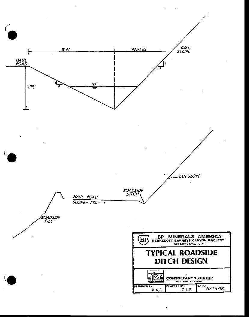
(
o
I'o
ROADSIDEDIfiCH t
uut RaADsloPE_ 27o _
r-\ BP MINERALS AMERICAUtf/ KENNEcorr BARI{EYS cANYol{ PRoJEcr
\-/ S.|t Ldc Cdnrt. Ul.n
TYPICAT ROADSIDEDITCH DESIGN
AE;,|{Y4EI 66ISULTAHTS GROUP- h l t a { ( C . l ! u l -x
xsrGN€D tt*.^.o. Io8^rrcD
tf-t-o- lo^t" 6t26/89
(o
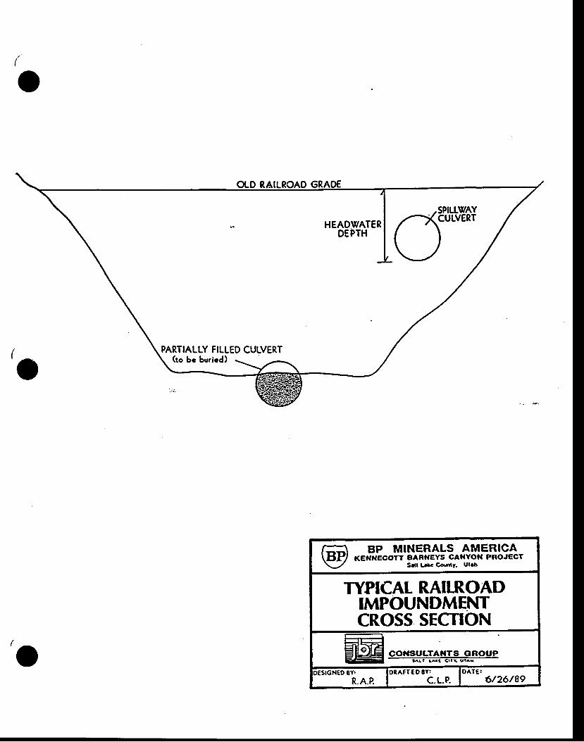
(
I' ^-v
PARTIALLY FILLED CULVERT
v
r-\ BP MINERALS AMERICA\tl.H/ KEI{fl€corr BARITEYS cAfiYota PRoJEcr\-/ Sdr L*. C..rtY. utrh
TYPICAT RAILROADIMPOUNDMENTCROSS SECTIONr + |-^-qA: I.EI COIISiULTAI{TS GROUP: - I l l a We <r l ! s l . r
>esrcxgo ov. lorerr€o av' IDATC:R.A.P. I c.t-.p. 1 6/26/8e
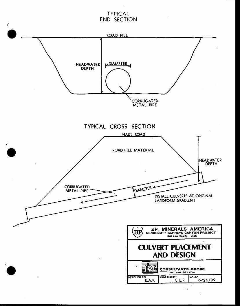
(
-v
TYPICALEND SECTION
ROAD FILL
CORRUGATEDMETAL PIPE
TYPICAL CROSS SECTION
(
o ROAD FILL MATERIAL
METAL PIPE
DWATER
TNSIALL CULVERTS AT ORIGINALLANDFORM GRADIENT
I-I BP MINERALS AMERICA\tl.F/ KElrflEcorr BARI{EYs cANYofl.PRoJEcr\-/ srlt L.k. co.nty. Ut.h
CULVERT PIACEMENTAND DESIGN
r€SrGt{€O gvt lOref feO gv. IOATEIR.A.P. I c.t-. p. | 6/26/89
{
^v
TIME OF CONCEMRATION CAIfT'IAIIONS
BENrs FORMT'IA
i^
-

^v
Time of Concentration (Kent's)
WS ldent=Barneys Canyon S
55 : CIIR\,IE NITMBER7160 = MAX ELEV5570 = UIN ELETf1590 = ELEV DIF
580 = wS AREA (ACRES)14OO = I.IENGTH OF THE LONGEST CIIA}INEI, (ft)
LCtcLC
255075
EI,EV CONTOI'R IENGTH5957.5 6600
535s 34806762.5 1960
0 .187856 = y0 .146161 = L ,0 .243601 = Tc
WS Ident=Barneys Canyon O
48 = CUR\IE NIIIIBER7657 = MAX EfrEV6720 = MIN EtEiV
937 = E[,EV DfF45.2 = WS AREA (ACRBS)2000 = LENGTE OF TIIE LONGEST CEAIINET, (ft)
EI,Eil/ COIITOI'R IJENGTH25 6954.25 1600s0 7188 .5 140075 7 422.75 400
0 .404513 = y0 .20407 = L
0 .340117 = Tc
tcLCrc

Time of Concentration (Kent's)
WS fdent=Barneys Canyon P
Iv
656s005520
980332
7440
6558605540
32095
2540
0.1461590.2668670 .444779
CT'RVE NT'MBERuA'( EtgffMIN ELEVELE|V DIFws aREA (ACRES)LENGTH OF THE I,ONGEST cHAtINEr, (ft)
LC 25&c 50rc 75
EI.,E|V CONTOI'R I,BNGM5765 37205010 48606255 1440
CI'RVE NT'MBER
Time of Concentrat ion (Kent,s)
WS Ident=Barneys Canyon N
(
^v
48770063001400
1183200
= CUR\IE NUMBER= MiA)( ELEV= MIN EIE[/= ELE1I DIF= WS AREA (ACRES)= LENGTH OF THE I€NGEST CHA}INEL
ELE\T COIITOI'R LENGTHT*, 25LC 50LC 75
66s070007350
235030s01350
( f t )
( f r )
0.4596230 .2799310 .464719
WS Ident=Barneys Canyon R
65 = CttR\rE NIIMBER8436 = t{,AX EfrEiV5475 = 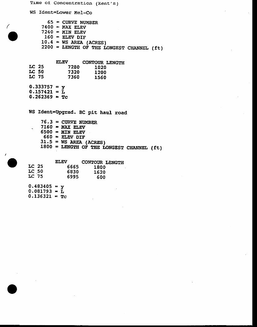
I
o
Trme of Concentratj_on (Kent,s)
WS ldent=Lower Mel-Co
65 = CIIRVE NT'ITBER7400 = MNK ELEX/7240 = MIN ELEV
150 = ELETV DIF10.4 = WS AREA (ACRES)2200 = LENGTTT OF THE ipNeesr crrAtrNEL ( f r )
ELE|I/ CONTCIIIR LENGTHLCLCI.,c
255075
' 16 .3
71606s00
65031.51800
0.48340s0.0817930.135321
728073207360
55555830599s
102012001560
18001620
600
0.3337570.1574210.262369
WS fdent=Uggrad. BC pit haul road
=y= f ,=Tc
= CITR\ZE NT,!4BER= MAX EtrEIf= !!IN EfrgV= ET,EV DIF= WS AREA (ACRES )= I.,ENGTE OF 8EE I.IoNGEST CIIAI{NEI,
ELE|V CONTOTIR LENGTH
( f t )
Le 25rc 50LC '?5
=y= f ,= T c
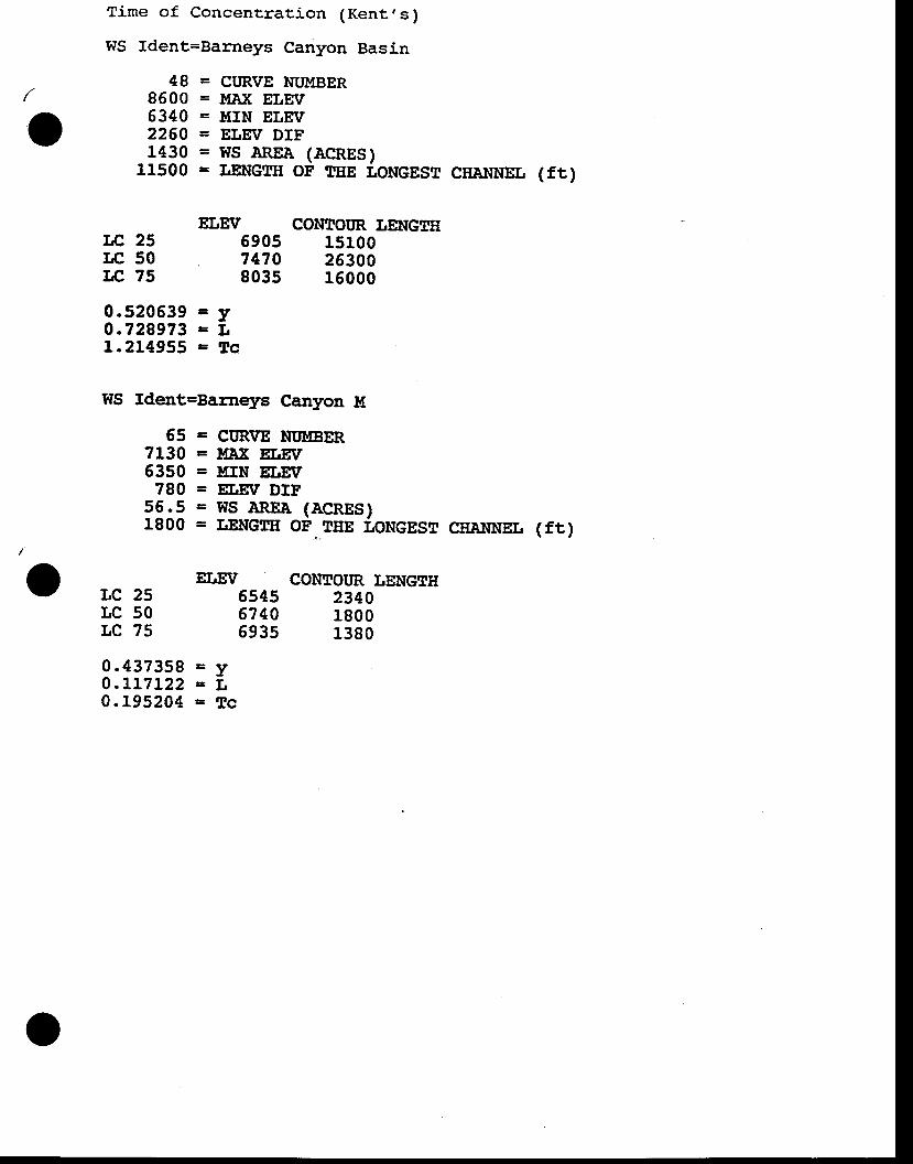
Time of Concentration (Kent's)
WS Ident=Balcneys Canyon Basin
-v
= CURVE NUMBER= }fNK ELE:V= MTN ELE[/= ELE\I DIF= WS AREA (ACRES )= I,ENGEII OF TEE TONGEST CEA}INET,
ET.,EV CONTOI'R LENGTH6905 151007470 26300803s 15000
WS Ident=Barneys Canyon t{
488600634022601430
11500
0.5205390.7299731.214955
5571306350780
55', .51800
0.4373s80.LL7L220. t95204
TE 25rc 50Tfr, 75
( f r )
( f r )
=y=t ,=Tc
= CT'R\IIE NI'}TBER= t llX ELEV= TIIN ELEIT= EI,EV DIF= WS AREA (ACRES)= LENGTE OF._TEE LONGEST CEANNEL
ELEit/ coNToItR TENGTHLC 25rc 50LC 75
6s4567 40693s
234018001380
=y= t t=Tc
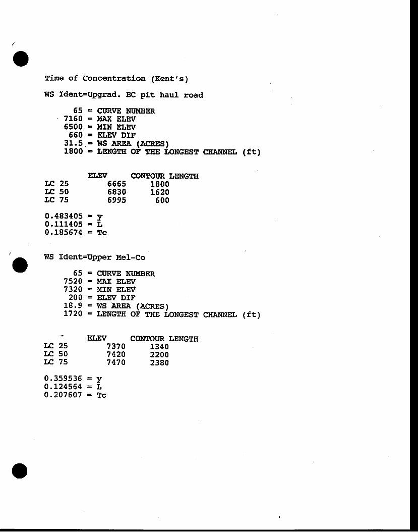
^f
fine of Concentration (Kent,s)
WS ldent=Upgrad. BC p.lt haul road
LC 25rc 50TE 75
6571506500
66031.51800
5575207320
20018.9L720
0.3s9s360.L245640.207607
= CIJRVE NT'MBER= t{AX EIJEV= I[[N EfJEiV= ELEV DIF= WS AR'EA (ACRES)= LEIIG|IE OF :tEE IIONGEST
ErrE[l CONEOITR ITENGTH
cEA}rNEr, (ft)
( f r )
655s6830699s
18001520
500
134022002380
0.4834050 .1114050 .185674
WS ldent=Upper Mel-Co
= CIIR\IE NT'MBER= l{ltiE ET,E|V= }IIN ELE|I/= ELEV DIF= WS AREA (ACRES)= LENGTII OF THE TONGEST CAANNEIJ
EIJE|I/ CONTOI'R IENGTH
=y= t t=Tc
r,c 25LC 50LC 75
737074207470
=y= l=Tc
(^
-
'o
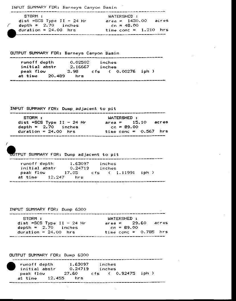
INti 'UT SUHMAF-:Y FOF;: Eartiel,s t latry,:,rr l iasirr
-v
sToF:t'l :d is t =Sr : :5 Type I I - t4 Hrdept t r = 2 .71 : t inc l ' r *sd u r a t i c , n = : 4 . O ( : r l r r s
t.JATEF;SHED :a r e a = 1 4 3 0 . O i J a € r e s
cn = 48. OCtt i r i re C': ' t lC = 1 .31(J hrS
OUTFUT SUMI{AF:Y FOF:: Earneys Eanyon Basin
runo f f dep t t ri n i t i a l abs t rpeak f l ew
at t i r r re 2O.4Bg
O. CtzSCt? i nclres2. 1F-€,67 i nclres
3 .98lrr s
c f s ( 0 .A0276 i ph )
INFUT SUI'IMARY FOR: Durnp. adjacent tc, pit
STORM zd is t =SCS Type I I - 24 Hrd e p t h = 2 . 7 O i n c h e sd u r r a t i e n = 2 4 . C l O h r g
TdATERSHED :a ree = 15 .10 ac res
cn = A9 .OOt i rne co t r c = 0 .367 h rs
VfpUf SUMMAEY FOR: Durrrp adjacerrt tc, pi t
r u n c , f f d e p t h 1 . 6 3 0 5 7i n i t i a l a b s t r O . : 4 7 1 ' 3p e a k f l a w 1 7 . O E
at t i r r ie 1 : . -J47 l r rs
i n c t r e si rrcfres
c f s t 1 . 1 1 9 9 1 i p h )
II{FUT 5Ut'11'lAF.:Y FOF.:: Dctrrrp 6300
STORI'I :d is t =St lS Type I I - t4 Hrd e p t h = ? . 7 1 : t i n c l r e sdur at i c'tr = !4. t-ttlt lrr s
WATEFTSHED !ar ea = 2-J.61_, ar: r eg
c n = 8 9 . O Otirr ie c, : ,n ' : = t- t .7E]3 l rrs
OUTFUT SUI{MARY FOF:: Dutrrrp 6300
r u r n o f f d e p t t ri n i t i a l a b s t rp e a k f l o w
at t i rrre L'.' .433
I .E3Ct '37Cr.?47 !- t
2 7 . E C llrr s
i n c l r e si nc l res
c f s ( O . - t 4 4 7 3 i p t r )
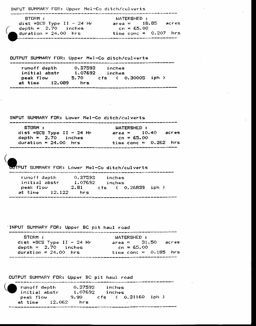
I t l f -UT SL l l ' lMAFiY FOF. : : Upper l ' l e1- f , , r d i tc l r /cur lver ts
(oSTOF:H :
d is t =Sr l :S Type I I - ?4 Hrd e p t l r = 2 . 7 C t i n c h e sdur at i c.tr = :4 . (-lO [r r g
T^IATEFJST{ED 'a r € a = 1 8 . 4 5 a t r e s
cr1 = 65. CtOt i rire c --,rlf = Ct . ?CJ7 [r r s
OUTFUT SUMI{ARY FOR: Upper Me l -Cc, d i tc t r /cu lver ts
runc , f f dept l ri n i t i a l a b g t rpea l r f low
at t i r r re L? .OB9
o .37993t . o7a92
5 . 7 C t c f slrr E
i n c h e sinc l res
( o .30005 i p h )
INFUT SUMMARY FOF:: Lower Mel-Co ditclr/culverts
sToRt't :dis t =SCS Type I I - 24 Hrdep th = 2 .7O inchesdura t i on = 24 .OO h rs
WATERSHED :a r € a = 1 C t . 4 O a c r e s
cn = 65. OCIt i rne co l l c = CI .2€ ,2 h rs
(Q"rt
sur l l rAqy FoR: Lc,wer Met- t r ,= di tch/curverts
r u n r , f f d e p t l ri n i t i a l e b s t rpeal': f l c,ur
at t i r r ie 7i ;- .7iJ2
r_r .37593L.Cr7A9?
: . 81 r f sh r s
i n r l resi nches
( o . 2 6 8 3 9 ip l r )
INFUT SUMMAF:Y FOF:: Upper Btr pi t l raul rc,ad
STOF:M :dist =St lS Typc. I I - - . '4 Hrd e p t h = 2 . 7 C t i n c t r g . sdutr at j. c,tr = !.{. tlttlt hr s
I fATEFISHED !a r € a = 3 1 . 5 0 a ' : r e g
C11 = €,5. t-lot i rrie ': t:'t1c = O. l Bg lrr s
OUTFUT SUMMAF.:Y FOR: Upper Ft l : pi t l raur l raad(oru t l r - , f f dep t t ri t r i t i a l a b s t rp e a k f l . = w
at t i r rre 1=. 06-,
Ct.373-Ji i t rc lresL . Q 7 A 9 2 i n c h e s
9 . 9 O c f = ( ( r . 3 1 1 6 0 i P t r )lrr s
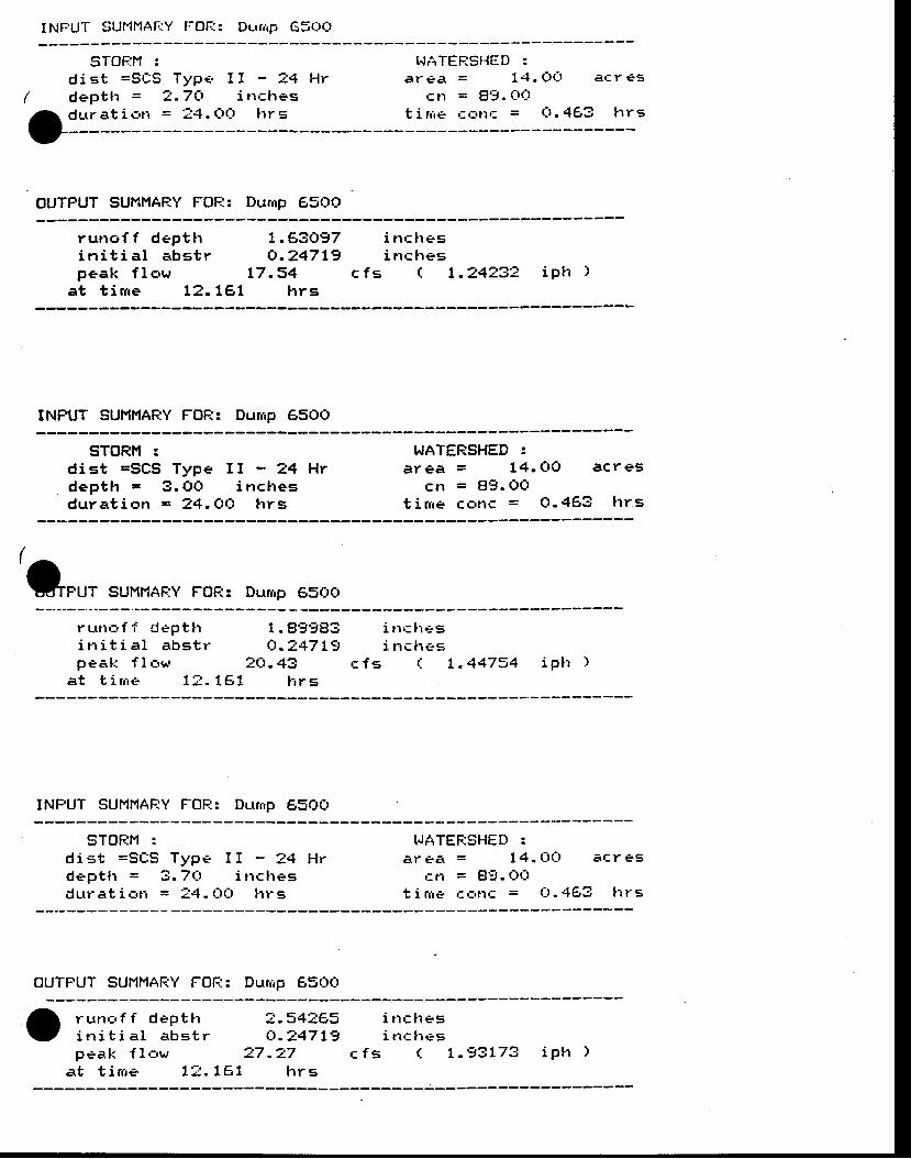
INFUT SUI'1MAf.:Y FOF.I: Dutrrrp G5(J(J
STOF;M :di st =Sr:S
d e p t h =Type. I
2 - 7 C l= t{. tltt-l
I - 3 4 H ri rrc lres
h r s
T.JATEF:SI{ED :ar ea = 1.+. CrO ac r €5
cn = Elg. CIQt i n ie can€ = (J . 463 l r rs
oi::::1::OUTFUT SUI'|MARY FOF:: Dunrp 65OC,
runof f dept l ri t r i t i a l a b s t rPeak f lc,w
a t t i n r e 1 2 .
7.F-3{J97o ,247 t9
L7 .34LEL h rs
i n c l r e si trclres
c f s ( 1 . 2 4 ? 3 2 ip l t )
INFUT SUMI'IAF;Y FOF:: Durrrp 6500
STORM :d is t =SCS Type I I - 24 Hrdept l r = 3. OO i nchesdura t i c rn = ?4 .QQ h rs
WATEF:SHED !area = 14 . CrCt acres
cr1 = 89. tlOt i rne cr3t lc = O. 463 lrrs
't"u,
suMHAFTY FoFr: Dunrp 6soct
r u n a f f d e p t t ri n i t i a l a b g t rpeak f I or^'
a t t i r r t e 1 : . 1 6 1
1 . 9 9 9 8 3o.3+7 L9
2(-1.43t ' i rs
i t rc l r*gi n c h e e
c f s ( 1 . 4 4 7 5 4 i p t t )
INFUT SUNf'{AFIY FOR: Dunrp 6500
STOF;M :d i s t = S C : S T y p e I I - ? 4 H rdept l r = 3 .7Ct i t rc l resdur at i orr = !4. t-tt:t lrr g
TJATEF:SHED :ar eei = 14. (J(J ai: r eg
cr-r = 89.(:rOt i r i re c ' : , i l c = Q.463 l r rs
OUTFUT SUMHAFiY FOI--.:: Durrip 65t-ttlt
r u n . r f f d e p t t ii t r i t i a l a b s t rp e a k f l o w
a t t i n r e 1 3 .
2 . 5 4 = 6 9Cr.247 t-j
2 7 . 2 71 6 1 f r r s
i t rc l resi n c h e s
c f s ( L . 9 3 L 7 3 ip t r )
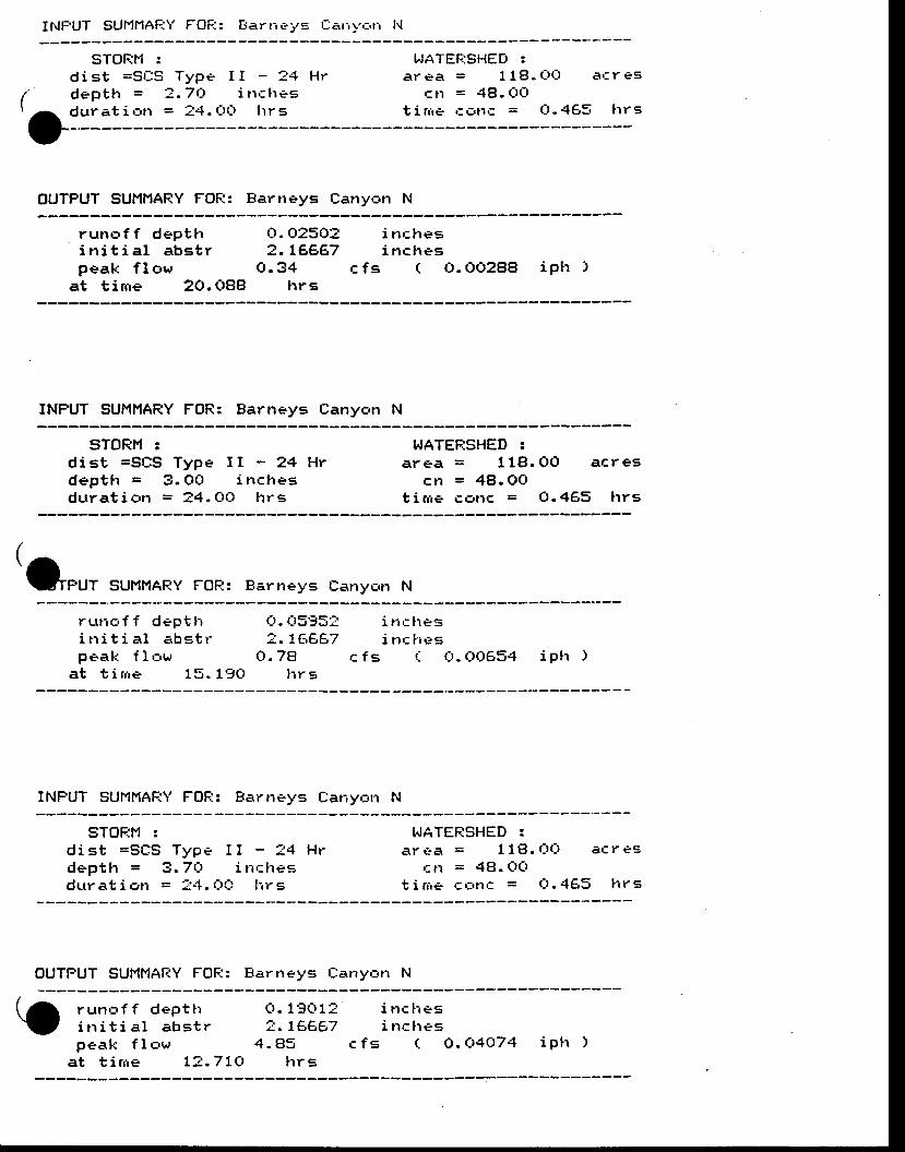
I l . lFUT SUl"l l ' lAFiY FOF.I: Eiarrreys Carir-,:r, t{
STOEH :d i s t = S E S T y p e Idepttr = a' .7(7
dur at i arr = 24. O(_l
I - 2 4 H ri rrc [res
t r r s
T,JATEF:SHED :a r e a = l l E } . C t L t a c r e s
cn = 48 . t l0t i r r ie cr3pf = Ct. 465 lrrs
(
OOUTPUT SUMNARY FOR: Bartreys Cany,=tr N
run|-a f f dept l ti n i t i a l a b s t rpeak f low
at t i rne 20. O88
i nc l resi nc l reg
c f s ( O. OO2BB iPtr )
rl. O25O22. LA6AT
o .34]rrs
INFUT SUMI''IARY FOR: Barneys Canyon N
STORM !d is t =St rS Type I I - 24 Hvdepth = 3. OCt i nclresdura t i on = ?4 . 0O t r rs
WATERSHED :a rea = 118 .OO ac reg
c]r = 4B.OOt i rrre cc.t lc = O.465 lrrs
(tef*u,
suMNAF:y Fot-':: Eartreys Earyc,n N
ru r rc , f f dep t t ii r r i t i a l a b s t rpea[ ' : f l '=ur
a t t i r r re 15 . 1gO
i t r r l regi t ' rct ' ieg
c f s r . O. CtO654 ipl t )
r-!. 0595"7- LEAAT
(1 .78l r r s
INFUT gUMf'lAFiY FOFI: Earneys tlar,yrrn tl
STOF;H :d i s t = S L I S T y p e I I - 1 4 H rdepth = 3 . 7 t l i nc l resdur at i on = t4. tlr0 t'rr e
I.JATEF:SHED :ar €.a = I 18. (J0 ac r eg
cr1 = 4f}. CrCtt i rrie c t:rn': = Q. 4€,5 lrr s
OUTf'UT SUI'IMARY FOl--;: Barneys Llanyc,rr N
run€ ' f f dep t f ti r r i t i a l a b s t rp e a k f I c , w
at t in re L? .7LCI
o. 1go 1?2. LAA67
4 . 8 5 c f slrr s
i n c t r e si n c h e s
( A.Cr4O74 ip t r )
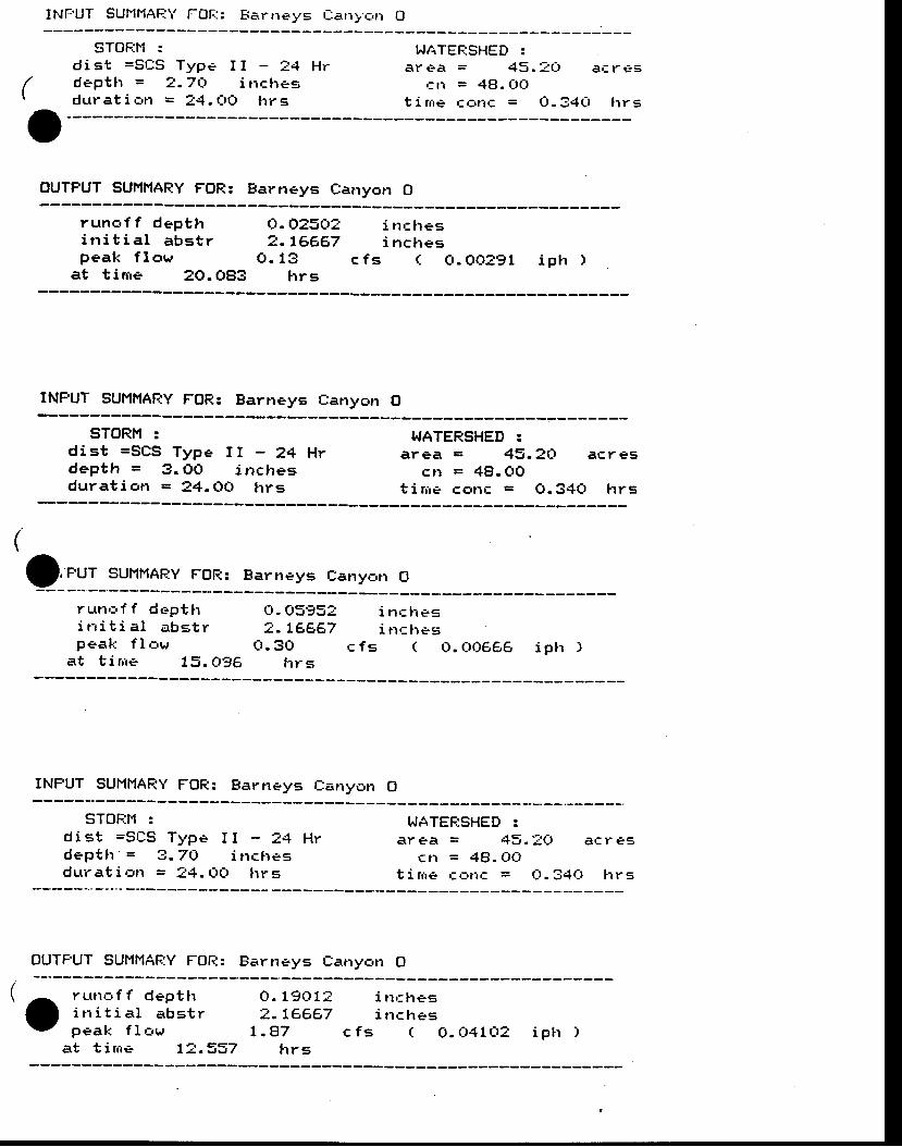
INFUT SUl.ll1AF:Y FOfi: E:arneys rl:arry.,:n O
STOF{M :d i s t = S t l S T y p e I I - ? 4 H rdept l r = 2 .7 ( r inc l rs .gdur at i arr = 24. t -r0 l rr s
T^,ATEFjSHED :a r e a = 4 5 . 1 0 a f , r e s
.:n = 48. CtOt i rrie r:L-inc = O. 34Q trrE
(
OOUTPUT SUMMARY FOR: Barneys Canyotr O
runc , f f dept l ri n i t i a l a b s t rp e a k f l o w
at t i rcre 20. OBg
O. O25Cr22. L6Ae7
O . 1 3 c f slrrs
i nc l resi n c h e s
( CI. OO291 iptr )
INPUT SUMt'lAFdY FOR: Barneys Canyon O
STORM :d is t =SCS Type I I - 24 Hrd e p t h = 3 . O O i n c h e sdura t ion = 24 . r lo l r rs
TTATERSHED :area = 43.2Cr acres
c l r = 4B.CIOt i rrre €or1tr = O. 340 hrs
(
f,'"u, sul,tHARy FoF:: Earneys canyc,rr o
ru t l ' 3 f f dept l ti t r i t i a l a b s t rpea[ , : f law
at t i rne 73. Q'JE
C). Cr595l2 . L A E 6 7
O . 3 O c f gfrr s
i n r l r esi nr l res
( O. t )06g6 ip l r )
INFUT SUMMAFIY FOFI: Earneys Earryotr 0
STOF:I'I :d i st =SrlS Type I I - 24 Hrd e p t l r ' = 3 . 7 1 - , i r r c h e sdur at i crrr = 14. CIC) lrr s
I^JATEF;SHED :a r e a = 4 5 . : Q a c r e E
cri = 4fi. (rrilt i r r ie c r , l r ' : = tJ .34O l r rs
OUTFUT SUMHAf.;Y FOI-r: Earneys Earryc,tr 0
runc , f f dept l ri r r i t i a l a b s t rpea l t f l rw
at t i r r ie L? .337
C,. 1g(r1?2 .7€687
t .B7 c f sh rs
i nr t resi trclres
( O. Oj l lO? i p t r )
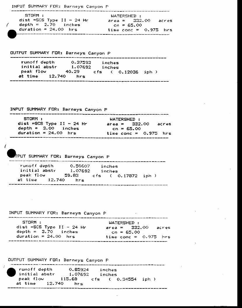
I l ' . lFUT SUf'1MAF;\' FGF.i: Barrieys Catryon F
(
trt
STOF;H :d i st =sr ls Typedept t r = 2 .7 { td u r a t i c , r r = ? 4 .
I I - ! 4 H ri n c h e s
CttJ hr s
I.JATEF;SHED :ar ea = 332. Crr_r ar r es
cr1 = 95 . OOt i lrie € r-.nt = t:t .973 lr r s
OUTFUT SUi{I4ARY FOR: Barneys Canyr:tr F
runc , f f depthi t r i t i a l a b g t r
O. 37593 i nclresL .O7E92 i nc l res
peak f l c ,w 4C) .29at t inre L2.74O lrrs
c f s ( 0 .1?036 i ph )
INPUT SUMMARY FOFi: Earneys Eanyon F
sToRf't :dist =SCS Type II - 24 Hrdept l r = 3. OO i nchesdura t i an = 24 .0 ( t l r r s
I",ATERSHED :area = 332. Ot l a€res
cn = 65. OCtt i n r e c o n c = Q . 9 7 3 h r s
O*u, suHr4AF:y FoR: Barneys Eanyc,n p
rLtr ic ' f . f dept l ' ri t r i t i e r l a b g t rpeal': f I ,:'w
O.scrge7 i nr l rest. t)7F-'g:l i trches
59.83 r fg ( ( r . 17a72 i p l r )a t t i r r i e 1 ? . 7 4 O l r r s
INFUT SUMI'IAF"'Y FOFI: Barneys Earryc,n F
STOF;M :d is t =Sr l :S Type I I - 24 Hrdept t t = 3 .7Ct i t rc l resdurat i c,ri = 14. t-tt-t lrrs
I^'ATERS}{ED :ar ea = 331. t]t] atr r es
Crl = f;,$. (t(t
t i r r ie , :a r lc = Ct . ' -J73 [ r rs
OUTF,UT SUMMAFiY FOF;: Barneys [ :any,=n F
otffil:,':E:';,peal: f I oqr
c ! .959:41 .Ct7A92
1 1 5 . 6 8
i t rc lresi trc lres
c f s ( 0 . 3 4 5 5 4 i p h )a t t i r r ie L2 .74O l r rs
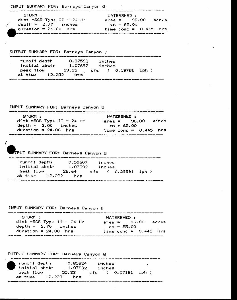
It{FUT SUI'IMAF;Y FOF:: Fa.rne-ys rl:arryc,ri G!
(
O
STOF:r'l :d is t =Sr :S Type Idept l r = 2 .7Crdurat i c,rr = i4. tltl
I - 3 4 H ri n c l r e g
h r s
I.JATEF:SJI-IED :a r e a = 9 6 . C t 0 a t r r e s
c n = 6 5 . O Ot i rr ie ctrr l ' : = t- t .4 '15 l rrs
OUTPUT SUI'II'IARY FOR: Earneys Canyon Gl
runo f f dep t l ri n i t i a l abs t r
O .37593 inches1 .u .7692 inches
p e a k f l o w 1 9 . 1 5 c f sat t inre L2.2BZ lrrs '
( O. L97eE iph )
INPUT SUMI',IARY FOR: Barneys Eanyc,n A
STORl"l zd is t =SCS Type I I - 24 HYdeptlr = 3. OO i nclregdura t i on = 24 .OO h rs
T^'ATERSHED 3area = 96 . Ot l ac r es
c n = 6 5 . 0 0t i rne con€ = O. 445 lrrs
O**t suHNARy FoR: Ear'eys cany,=n o
run l . f f dep t t ri t r i t i a l a b s t r
Ct.5(J6(:)7L .Ct7697
peak f l ,=ur 28 . 64at t i rrie 1-J. =8? tir e
i t r t l - resi t t c l t t - "s
c f s ( 0 . : 9 5 9 1 i p l t )
INPUT SUMMAFiY FOF;: Barneys Eanycrr G
STOFJN :d is t =St lS Type I I - ?4 Hrdept lr = 3. 7(! i r lc l -resdur at i urrr = ?4. Ct{t lrr s
I.IATEF.:SHED :ar ea = 96. e(: ! af ,r es
Cl'l = 85. f-r(,t i r r ie €.: , t - . r ; = Q-4.+5 lrrS
OUTFUT SUMf'lAf-.:\ ' FOF:: Earneys Eanyrrn O
rLr t l ' : r f f dept t ti t r i t i a l a b s t r
O.859{*4t .c rTega
peal ' : f l , rur 55. 33at t i r r ie L: ' .2?3 lrrs
i t rc lresi nc f res
(c f s C t . 3 7 t A L i p t i )
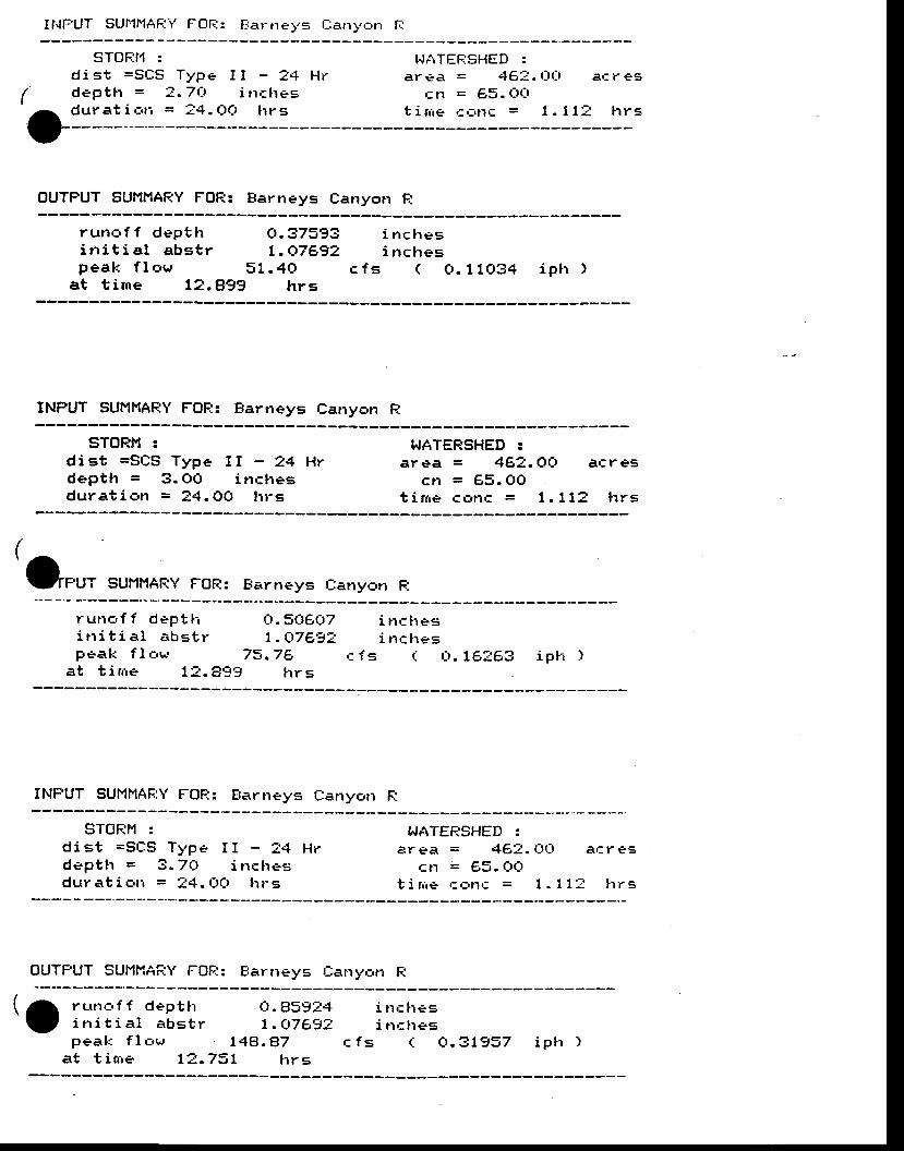
It{f-UT SU|'1MAF;Y FOI--;: t iartreys Canyc'n f-i
(
-17
STOFit'l :d i st =St lS Type Id e p t h = ? . 7 r 7durat i . i r , = !4. t )O
I - 2 4 H ri n r l res
trr s
T.,ATEF:SHED :ar ea = 46:. O() a, : r es
Cr-l = 65. Ot_tt i r r i e r * r r c = 1 . 1 1 t l r r s
OUTFUT SUtltlAF:Y FOR: Earneys Canyotr F;
runc, f f depthi n i t i a l abs t rpeak f I c,w
at t ime L2.A99 hrs
Ct .37593 i nchesl. t"r^7492 i nclres
5 1 . 4 C 1 c f s ( O .11034 i ph )
INFUT SUMMARY FOE: Earneys Canyc,n R
sToRH :d is t =SCS Type I I - ?4 Hrdept l r = 3. OO inc l resdu ra t i on = 34 .OO l r r s
WATERSHED :area = 4g?. Crt l atrres
c r l = 6 5 . 0 0t i n r e c t r r l c = 1 . 1 1 2 h r s
(
O"rt sullttAey FoR: Earrreys Eanyen F..
ru r l r - r f f dept l - r 0 .5CI6e7 i r rc l resi n i t i a l e r b s t r 1 . t 7 A - i ? i n c l . r * speak f l , rw 73 .7A c fs ( : C) . t1?6e ip t - r )
a t t i r r re 72 .A- i9 h rs
INFUT SUMMAF"Y FOFI: Eartreys C:anyerr R
sToFiH :d is t =St lS Type I I - " r4 Hrd e p t l r = 3 . 7 Q i n c l r e sdur at i c,ti = ?4. Crf_r trr s
T,,ATEFjSHED :area = 4€,t . Ot_t a ' : res
cn = €,5. CxJt i r r ' , r+ ' : r : , t l t r = 1 .11 : l r rS
OUTFUT SUMI"IAFIY FOF.;: Barneys Eany,:n R
tjlffil:,':i:';,'pea[ : f lo r , r 148.87
a t t i m e L ? . . 7 3 L l r r g
cl . BS9:41 . Q 7 6 - J z
i n c l r e si nc l res
(c f s Ct.3L937 iplr ' ,
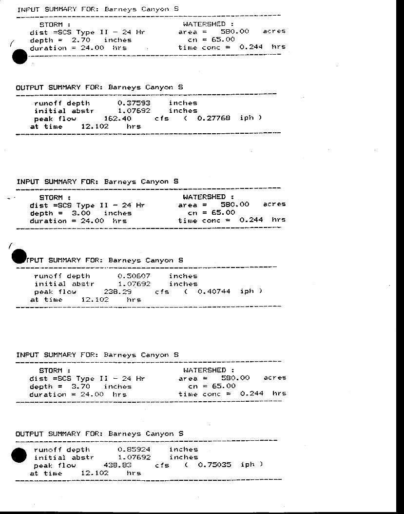
IIIFUT SL,MfiAfiY FOF-;: f ' ts.rrleys Ilatryarr 5
9TOFit4 :d is t =Sr l :S Type Id e p t l r = 2 . 7 Qdurat i c,rr = !4. tJt-t
I - ? 4 H ri t rches
l i r s
I.JATEF:SHED :ar ea = sEl(_l . (:x-r a€ r eS
c n = 6 5 . O Otirr ie cFi ' lc = O. - /44 trrs
OUTFUT SUI'IMARY FOF:: Barneys Canyc,tr S
runc ' f f dep thi n i t i a l a b s t rpeak f l sw
at t i t r ie 12 .
o.37593t . U.7692
1 6 2 . 4 C 11O2 l r rs
i n c h e si nc l res
c f s ( O. 277AA iP l t )
INFUT SUI'IMAF:Y FOR: Barneys Catryotr S
sToRl'l :d ist =SCS Type I I - 24 Hrdepth = 3 . OO i r rchesdur at i ott = 14. CIC) l', r g
WATERSHED 3area = 5gQ. r)Ct acres
cr1 = 65. OOt i rrre cc,tl€ = 0.244 lrrs
/ _
-[FUT SUilt' lAF:Y FOF:: Earneys E:any6p S
r uttr,i f f dept lti t r i t i . r l a b s t rpeal l f l , : ,w
at t i r , ie 1 - . ' ,
(:,. 565rr-17i . t 7 6 - J 2
' :38. ?910: l r r s
i n c l r e gi nci-res
c f s ( C I . 4 Q 7 4 4 i P t r )
INFUT SUt'll ' lAFjY FOF:: Eartreys f:any,:,tr S
STOF:M :d i s t = S t l S T y p e I i - 3 4 H rd e p t h = 3 . 7 C t i r r c l r e sdurat i r-r t r = ?.1 . t - t i - t l r rs
I.IATEFTSHED :area = sg t l . OO ar res
cr l = 65. t1Ot i tne r : ' f t t t r = O. t44 l rr=
OUTFUT SUHMAFjY FOF:: Fartreys tlatry,=tr S
run , : , f f dep t l ti t r i t i a l a b s t rp e a k f l a w
at tirrie L'r..
t_ r .859141 - CrTE-tZ
4 3 8 . 8 3LOZ lrrs
i t rc l resi trc lr es
c fs ( C I .73 i t33 ip l ' t )
APPENDD(E
GRADING FOT'NDATION SPECIFICATIONS
BP MINERALS AMERICABARNEYS CANYON PROJECT
Salt Lake County, Utah
T9CHNfCAL SPECIFfCATfON - No: 87105-01
STTE WORKS
LEACH PAD AND POND CONSTRUCTION
ACCESS ROADS
A. PATWARDHANENGTNEERTNG, INC.
PREPARED BY:MTNE AND MILLJune 27, 1988
Reviewed: Paul Kaplan - (SHB)
Zip Zavodni - (BPMA)
Rober t Parker - (BPMAI
Approved:BP M:nerals America
l r t l l lr f r l l lr t l l l l
Rel .eased for Construct
Revis :ons
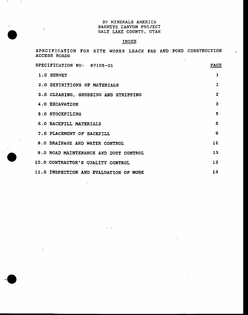
o3P MINERALS AMERICA
BARNEYS CANYON PROJECTSALT LAKE COUNTY, UTAH
rNDEX
SPECIF ICATION FOR STTE WORKS LEACHACCESS ROADS
SPECIF ICATfON NO: 8?1O5-O1
1.O SURVEY
2.O DEFINITIONS OF MATERIALS
3 . O CLEARING, GRUBBIT{G AND STRIPPING
4.O EXCAVA?rON
5.O STOCKPILING
6.0 BACKFILL MATERIATS
7. O PLJICEMENT OF BACKFTIL
8.O DRAINAGE AND WATER CONTROL
9.O ROAD MAINTENANCE AND DUST CONTROL
10.O CONTRACTOR'S QUALITY CONTROL
11.O INSPECTTON AND EVALUATION OF TiTORK
PAD AND POND CONSTRUCTION
PAGE
1
1
2
3
5
t2
13
13
13
5
9
o
o
BP MINERALS AMERICABARIIEYS CANYON PROJECTSALT LAKE COUNTY, UTAH
SPECIFTCATTON FOF. ST?E } 'ORKS LEACH PAD AND POND CONSTRUCTTONACCESS ROADS
1 .O SURVEY
1.1 The Contractor wiL l establ ish the contro l , l ines basedon benchnarks and nonuments shown and shal l beresponsS.ble for al l surveying to control the work.
1.2 All su:rvey work wil l be subJect to checking by theOwner I s Representative.
DEFINITTONS OF IIATERTALS
The naterials for earthwork and enrbankment construction aredefined in detai l as fol, lows:
2.7 Rock: A solld nass of material exceeding one cubicyard in volume, which cannot be effectively loosenedor broken down by rlpping in a single pass with alate nodel dozer mounted hydraullc r ipper equippedw i t h a s i ng le d i gg ing po ln t ; o f s t anda rd manu -facturers desigm adequately slzed for use with andra ted a t a rn in imun 41O-ne t f l ywhee l ho rsepoweroperating Xl low gear.
2.2 Sol l : The super f lc ia l mant le of unconsoJidated orpa r t i a l l y conso l i da ted na te r i a l t ha t nea r l yeveglnrhere covers the rock rnay be of natural or man-nade o r i g in ( f i l ] ) .
2 .O
2 .3 So i l Componen ts :
2 .3 .1 C lay : P las t i c so l , l wh lchStandard *2OO sleve.
Nonplastlc sol l whlchStandard #2OO sieve.
passes a U.S.
passes a U.S.2 .3 .2 S i l t :
2 . 3 .3 Sand : Solid mineral grains whlch Pass aU.S. Standard #4 sieve and retainedon a #2OO sieve, non cohesive.
o
3 .O
2 . 3 . 4 G r a . z e l : S o l . i d n i : : e : a l . : : a s s e s w h i c h a r er e t a i n e d o n a U . S . S t a n d a r d # 1s i e v e , a n d a r e L e s s t h a n t h r e einches in maxinum dimensions.
2 .3 .5 Cobb l .es : So l iC m ine ra l . r asses wh ich a re no tg rea te r t han 12 i nches bu t a relarger than three inches in rnaxiroum
. d inensions.
2.3.6 Boul .ders: Sol id n inera l l lasses which are notg rea te r t han one cub i c ya rd i nvo lume , bu t a re l a rge r t han t 2inches in naximum dimension.
2 .4 Topso i l
For purposes of this Speclf ication, topsoil shall bede f l . ned as so i l o f any g rada t i on o r deg ree o fp last ic i ty which conta ins s lgn i f icant quant i t ies ofvisually-identl, f iabl.e vegetative matter, sod, roots,or humus. As a miniynun, the upper six inches of soilbelow the natural. ground surfaCe shar,J. be consideredtopsoil- Topsoit depths sharl be as defined in theGeotechnica l . Repor t , o ! as def ined by the OwnerfsRepresen ta t i ve . Topso i l as de f i ned he re in i s no tsu i t ab le f o r use as cou rpac ted eubankmen t f i l rrnaterial, , and shal, l be str ipped frorn al l f oundationsurfaces.
CLEARTNG, GRUBBTNG AND STRTPPING
3 .1 Clearing, grubbing and stripping shal.l be perfornedas regui red and as d i rected by Ownerts Represen-tat ive.
clearing wil l , censist of removal and dlsposar of altt r ees , b rgsh , l ogs , L imbs , wood , g rass , rubb ish ,structures and al l other obstructionJ resting on thesurface of the original ground. Also incl,uded ls theremova l o f b rush and g rass roo t rna te r i a l wh ichcompose approxirnately the top 6 inches of surfacena te r i a l i n some non-ag r i cu l t u ra l a reas . UnJessotherwise shown, clearingr shall be perforned withinthe fo l l .owing l in i ts :
Wi th in the l in i ts o f and 10 f t . outs ide thel i n i t s o f t he excava t i on , f i l l s ands tockp i l es .
3.2
4 . O
Along roaCways 30 feet mjn i rnun on each s ideof the center . l ine or 5 f t . beyond the cutshoul .der or toe of f i11.
3, .3 Grubbi .ng wi l l consis t o f the renoval . and d isposal o fa l l 's tumps, bur ied logs, s tubs and roots large= than7- t /Z inch ln d ianeter wi th in the areas c leared to adep th o f 2 .O f ee t be low o rS .g ina l g round . g l i t h inareas to be f:.1,1ed, stunp holes and depressions shal.Ibe back f i l l ed and compac ted . W i th in a reas to beexcavated, stunp holes may be left open.
3.4 Stripping wil l consist of the removal of the topsoilas def ined in paragraph 2.4.
3.5 All clearing, grubbing and str ipping operations shal. linclude the preservation from injury or defacenent ofa]l . trees, vegetation and objects Jocatcd beyond oroutside the work l irnits.
SXCAVATTON
4 . t Scorre of Wot&
This Speci f icat ion covers the requi red excavat ion,the removal and ptoper uti l ization or disposal of al lexcavated material and the shaping and finishing ofafl excavation work to the reguired l j .nes, glades,and cross sections as shown on the drawings.
4.2 Cl,assif ication of al. l excavated materia. l .s shall beincl,uded ln the fol lowing:
a. Cornnon excavat ion shal ] inc lude a] l mater ia lsexcept those defined as rock or topsoil .
b . Rock excava t i ons i nc lude a l l , ma te r i a l . s wh ichcanno t be removed as de f i ned . l n sec t l on 2 . texcept by blastlng and al,t detached aasses ofth i s ma te r ia l exceed tng one cub l , c ya rd each .The presence of such boul,ders or rock fragnentssha l , l . no t l n l t se l , f be cons ide red su f f i c i en tcause t o change t he cJass i f i ca t i ' on o f t hesurroundlng naterial.
The cl.ass of excavation shall be determined by theOwner or i ts designated representative on the basiso f h i s de te rm ina t i on o f t he cha rac te r o f t hemate r ia l s t o be excava ted and the p reva i l i ng s i t econdi t ions.
4 .3
'o
4 . 4
4 .5
Su i t ab le e : : cava ted na te r i a ] s sha l f be u t i l ' i zed i nbackf i l ls . Unsui tab le or excess excavatec l mater ia fshal.- be disposed of at waste locatj.ons :ndicated bythe Owner ' s Represen ta t i ve .
Pockets of unsui tab le mater ia ls wi th in the l in i ts o fexcava t i on sha l . l be renoved and was ted . Theexcavat ion shal l be f in ished to the l , lnes, grades,and typ icat sect ions shown on the drawings ot asdi rected by the Owner 's Representat ive.
The nethod of excavation shall not weaken surroundingareas or danage structures or parts thereof that areconpleted or under constructlon. Exist ing structuresand u t i l . i t i e s ad jacen t t o excava t i ons sha l l beprotected and supported to prevent sett lement.
Du r i ng g rad ing ope ra t i ons , t he su r f ace o f t heexcavated area sha.l l be maintained in such condit ionso as t o ensu re adegua te d ra i nage . Wa te r i nexcava t i ons sha l , l be con t ro l , l , ed and removed .D5.scharge from pumps shal,l be wasted at Jocations asdirected. Springs or seepage encountered shall ' bereported inmediately and controJled as directed.
Af ter ln i t ia l c lear ingr and grubbing, excavat ion ofany sof ter so i ls to the contact o f re la t ive ly f i rnsoils shal. l . be performed only at the dlrection of theOwnerrs representation. If required, overexcavationshall be perforued in ernbankroent foundations and baseareas for the Jeach pad, ponds, a:rd perirneter dikefound ,a t i on a reas . Con f i rma t ion o f adegua te sub -excavation and exposure of firn soil,s shall be madeby the Ownerts Representative
Except as otherwise showtr, gradi.ng tolerances shaLlbe zero to Binus o.1 ft . for horizontal, and slopedplanes of common excavatlon and zero to minus O.5 ft.for borlzontal and sloped planes of rock excavation.Rock cut 'slopes shall be seal.ed of all loose rocksand f r ag rnen t s , and l e f t l n a nea t , ' sa f e andworknanlike condition.
4 .7
4 . 6
4 . 8
4 . 9
-(a
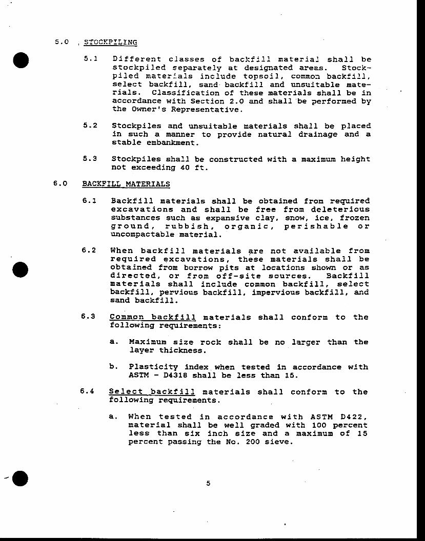
5 . O , STOCKPILING
5 .1 D i f f e ren t c f asses o f back f 1 l l , r na te r i a l shaL l bestockpi l .ed separate ly at des ignated areas. Stock-p i l ed ma te r - : , , a l s i nc l . ude topso i l , comn,o : t back f i l . l ,se lect backf i l l , sand.backf i l l , and unsui tabJe mate-r ia l ,s . Class i f icat ion of these rnater ia ls shal l be inaccordance with Section 2.O and shall , be performed bythe Ownerrs Representat ive.
5 .2 Stockpiles and unsuitabl.e material,s shall be placedin such a manner to provide natural, drainage and astable embankment.
Stockpiles shall be constructed with a rna:rimum heightnot exceeding 40 ft.
6.0 BACKFTLT MATERTATS
6 .1 Backfi l l , naterj,al,s slral l be obtained fron requiredexcava t i ons and sha l l . be f , ree f ron deJ .e te r i oussubstances such as expansive cJ,ay, snow, ice, frozeng i round , r ubb i sh , o rgan i c , pe r i , shab le o ruDcomPactabl,e material, .
When back f i l l ma te r i a l s F re no t ava i l ab le f r onregu i red excava t i ons , t hese ma te r j . a l s sha . } l . beobtained from borrow pits at locations shown or asd i r ec ted , o ! f r o rn o f f - s i t e sou t ces . Back f i l lmater ia l ,s shal l inc lude coBtron backf i l . l , se lectbackfi l l , pervious backfi l , l , i rnpervious backfi l l , andsand backf i l , l . .
Connon back f i l l . ma te r i a l s sha l l con fo rm to t hefoll.owing reguirements :
a. Maximun size rock sbal, l be no larger tban thelayer thickness.
b. Plasticity index when tested in accordance withASTM - D4318 shal, l be Less than 15.
Se l . ec t back f i l l na te r i a l s sha f l con fo rn t o t hefollowing requirenents .
a . g fhen t es ted i n acco rdance w i t h ASTM D422 ,naterial shall . be well graded witb 1OO percentless than s ix inch s ize and a naxi rnum of 15percent pass ing tbe No. 2OO s ieve.
6 .2
6 .3
5 .3
6 .4
-O
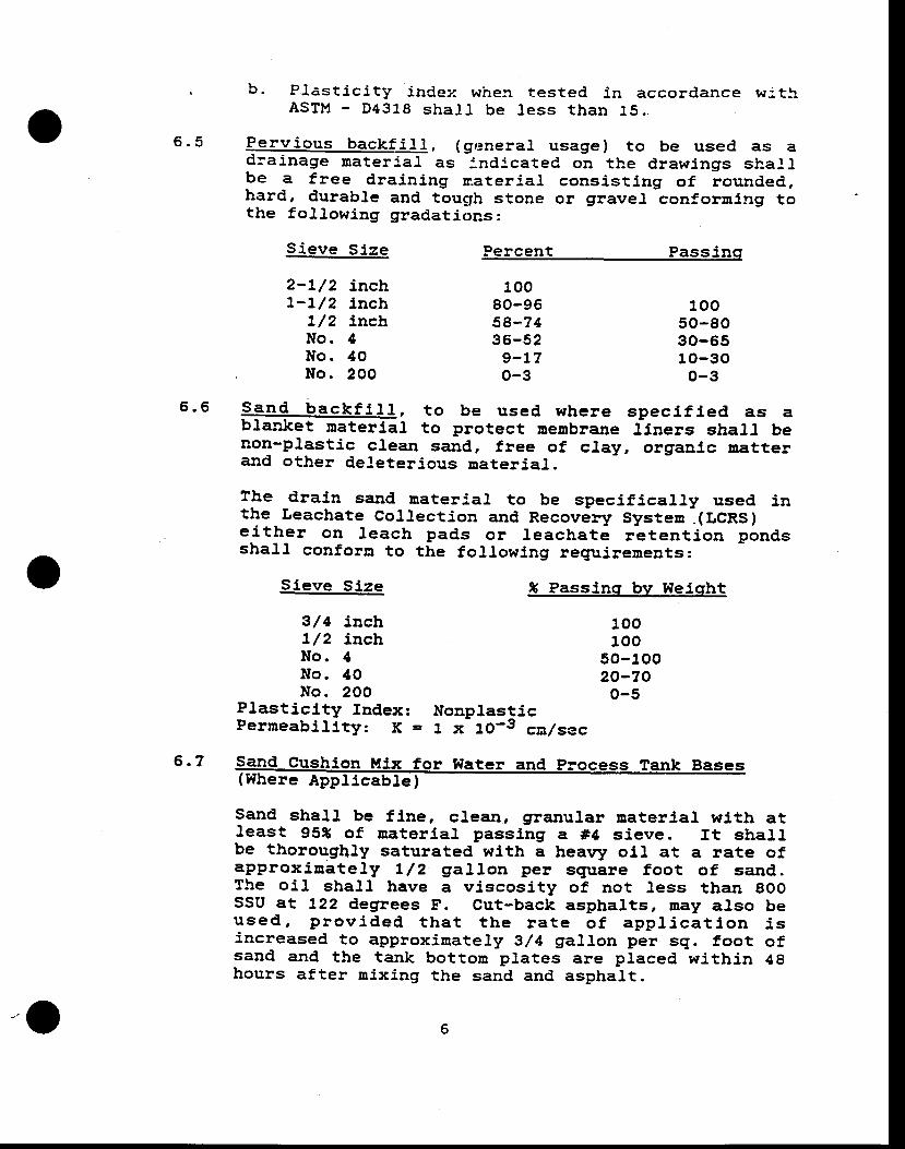
6 . 5
b. Plast ic i ty inCez when tested in accordance w: . t lASTM - D4318 sha l t be l ess than 15 . .
Perv ious backf i l l . (genera l . usage) to be used as adlainage nateri.al. as :nd:cated on the drawings shallbe a free draining naterj.al consist ing of rounded,,hard, durable and touglh stone or grave! conforning tothe f ol. l .owing gradations:
Sieve Size
2-L/2 inchl -L /2 i nch
7/2 inchNo . 4l{o. 40No. 2OO
Sieve Size
3/ 4 incht /2 inchNo . 4No . 40No. 2OO
Plasticity Index:Perneabil i ty: K =
Percent Passinq
10080-9658-?436-52
9-17o-3
10050-8030-6510-30o-3
* Passinq bv l{eicrht
100100
50-10020-70o-5
6 .6 @, t o be used whe re spec i f i ed as abl'anket roaterial to protect menbrane Liners shal,t benon-plastic clean sand, free of clay, organlc matterand other deleterious material.
lhe drain sand nateria. l . to be specif ical ly used inthe Leachate collection and Recovery systen.(r.cns)e i ther on leach pads or Leachate retent ion pond,sshall conforn to the foJ,lowing requirements:
Nonplastic1 x 1O-3 cnlsec
6 .7 s(Where Appfi-E e
!)
Sand shal, l be f ine, clean, granul.ar material wlth atleast 95S of material passing a #4 sieve. It shallbe thoroughly saturated with a hearry oll at a rate ofapprox i t ra te l ,y L /2 gal lon per square foot o f sand, .The oi l shall have a viscosity of not less than gOOSSU at L22 degrees F. Cut-back asphaltsr Der! also beused , p rov ided t ha t t he ra te o f app l i ca t l on i sincreased to approximately 3,/4 gallon per sq. foot ofsand and the tank botton plates are placed within 48hours after nixing the sand and asphalt.
-O
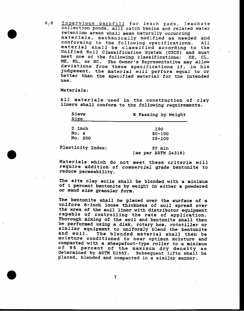
6 . 8 f n_p -e rv i ous back f i f l . f o r . l . each paCs , f eacha tecol lect ion ponds, mi l f catch baslns and reJ.ated waterretention areas shal.L mea,n natur;r lJ.y occurringna te r i a l s , r nechan i caJ ! y : nod , : f i ed as needed andcon fo rn i ng t o t he f o l l ow ing $pec i f i ca t i ons . A l lna te r i a l sha l l . be c j . ass i f i ed acco rd ing t o t heUn i f ; ed So i l C lass i f i ca t i on Sys ten (USCS) and mus tneet one of the fo l lowing c lass i f icat j ,ons: CH, CL.M8, ML, or SC. The Ovrnerrs Representative may al lowdev ia t i ons f r o rn t hese spec i r i ca t i ons i f , i n h i sjudglenent , the nater ia l wi l ,1 per f orn equal to orbetter than the specif ied material, fcr the intendeduse .
Ma te r ia l s :
A l t na te r i a l s used l n t he ccns t ruc t i on o f c l ayliners shall. couforrn to the following requirements.
SleveS ize
X Passing by lleight
3 inchNo . 4No. 2OO
Pl.asticity Index:
10050 -10025-100
2O min(as pe r ASTM D4318)
Mate r ia l . s wh ich do no t mee t t hese c r l , t e r i a w i l l .requi re addi t ion of commercJal grade bentoni te toreduce perneabil i ty.
The site clay sol,ls shall be blended with a minimurnof 1 percent bentonite by weight ln either a powderedor sand sl,ze granular forn.
lhe bentonite shall be placed over the surface of aunl ' forn 8-inch loose thickness of soi l spread overthe area of the soil liner with dlstributor equipnentcapab le o f con t ro l l i ng t he ra te o f app t i ca t i on .Thorough nixing of the soil. and bentonite shar.] tbenbe perforned usl,ng a disk, rotary hoe, rototi l ler orsini lar eguipnent to uniforrnly blend the bentoniteand so i I . The b !ended ua te r l a l sha l l t hen benois ture condi t l ,oned to near opt imun nois ture andcompacted with a sheepsfoot-t1pe rol ler to a minimumo f 95 pe rcen t o f t he max imum d ry dens i t y asdeterrnined by ASTM D1552. subseguent l i f ts shal, l beplaced, b.l .ended and compacted in a simil.ar manner.
7
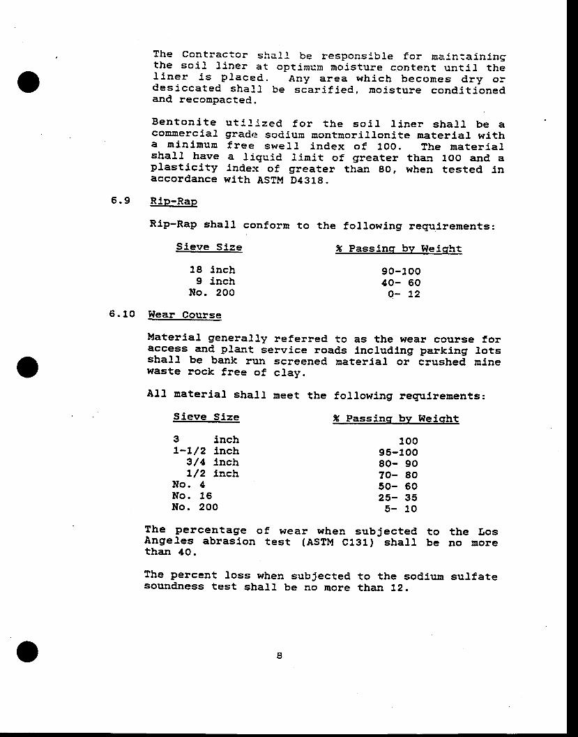
The contractor shaf l be respons:b1e for malnta in ingthe so i l , L iner at opt imum noi ,s ture content unt i l , thel i ne r i s p l aced . Any a rea wh i ch becomes d ry o rdes i cca ted sha l l be sca r i f i ed , rno i s tu re cond i t i onedand recompacted.
Ben ton i t e u t l f i zed f o r t he so i J . l i ne r sha l l be acommercial gradr: sodium montnori l lonite naterial witha m in imum f ree swe l l . i ndex o f 1oo . The ma te r ia l .shal ' l have a l iguid l irnit of g'reater than loo and aprast ic i ty index of greater than go, when tested inaccordance wi th ASTM D4318.
5.9 Rip-Rap
Rip-Rap shall conform to the fol lowing reguirements:
6.10 Wear Course
Materiar general ly refered to as the wear course foraccess and plant service roads including parking lotsshall be bank run screened nateriar or Crushea minewaste rock free of clay.
Al,l naterial, shalJ, rneet the foll.owing requlrements:
Sieve Size
18 inch9 inch
No. 2OO
Sieve Size
3 lnchl - l /2 inch
3/4 lncht/2 inch
No . 4l { o .16l{o. 2OO
* Passinq bv 9feicrht
90 -10040- 60
o - 72
S Passinq bv Weisht
10095-10080- 9070- 8050- 5025- 35
5 - 10
The percentage of wear when subjected to the LosAngeles abrasion test (Asll , t C1g1)
- shall . be no Dore
than 4O.
The percent loss when subjected to the sodium sulfatesound,ness test shal.l be no more than 12.
o
6 . 1 ,1 A11 back f i 11 sha l . f con f o rn w i i h i n t he t o Le=3 -cesspec i f 1ed t o t he l i nes , g=ades , sec t i ons ; r ndelevat ions shown.
6 .12 Except as otherwise shown , grading tof erances sia.l Ibe p lus or minus o.2 f t . for a l l exposed sur faces ofback f i l l .
6 .13 Backf i t l mater ia ]s shal . l not be p laced on snow, iceo r f r ozen g round su r f aces . A l . 1 excava t i ons t oleceive backfi l l shall be cleaned of al. l trash anddebris. Al l f oundations for embankments shal ' l ' bef r ee f r o rn any o rgan i c r na t t e r . A l l f ounda t i onexcava t i ons s r ra r r be app roved by t he owne r I sRepresentative prior to placing any f i l t roaterial.
7.O PLACEMET{T OF BACKFTTL
Enbankrnents and fitls shall be constructed to the Lines andgrrades strown on the constructlon drawings.
The f i f t shatl, be placed in approxiuately horizontal, layersno t exceed ing e i gh t i nches i n Joose t h i ckness . Thedis t r ibut ion of mater ia l ,s wi th in the f i l l shal , l . be suchthat no I 'enses, pockets, or streaks of materia.I d' i f feringsubstant ia l ly in gradat ion or texture f rom surroundingmateria] in the f i l l zone exist. The various f i l l zones inthe embankment shall be carried up together such that thesurfaces of the zones at adjacent sections do not vary inelevatl,on by Dote than three feet. If the surface of thefi l l becones too dry or bard to permit suitable bondingwith the subsequent layer, the naterial shall be Loosenedby scarifying or disc harrowingr, noistened, and recompactedbe fo re an add i t l ona l l t f t l s p l aced . Unde r noc l . rcunstances shal l any f i l l be p laced in s tandl 'ng orponded water . F i t l shal l , not be p laced upon a f rozensu r face , no r sha l . l snow , 1ce , oB f r ozen so l l belnco rpo ra ted l n to the f i l l . Du r ing cons t ruc t l on , t hesurface of the fill shall be nal,ntained with a cro$rn orcross-slope that wit l ensure effective surface drainage.
I{trere fill is to be placed against existing slopes steeperthan 6 to 1 (hor lzonta l . to ver t lca l ) , the s lope shal l bebenched at least I feet horizontal ly. for every 2 feet off i l l height so as to prevent a weakened sflp plane betweenthe f i l l and natural ground.
o
t ' , ' l
7.2
P:: l ish Gradinq Tolerances
Fin ish grading and excavat ion shal l be per forned towi th in p lus or minus O. 1 f t . o f the L ines, gr rades,elevations, and sections sbown except that subgradesof roads and parking areas shal. l be graded to withinO .OS f t . o f t he J i nes , g rades , e l eva t i ons r iDdsections shown.
Moisture Contro l
During the cornpactj,on operation of al l f i l t materia. l ,the surface of the f i l . l and the material being placedwil,l be rnaintained within the moisture content r€rngerequLred to peruit proper conpaction to the specif ieddensl ty . lhe moisture content wi l l be d is t r ibutedunifornly tbroughout each layer of f i l l . Averageplacernent moisture wil, l be at or sl ightly above theop t imum mo l , s tu re con ten t . The mo is tu re con ten tdu r ing compac t i on sha l l be na in ta ined w i th in thel i n i t s o f lX beJow to 3 t above op t imum uo is tu recontent as deternined in accordance with ASTM D155?.Any ma te r ia l co rnpac ted d r i e r t han th i s w i l l besca r i f i ed r l no i s t u re cond i t i oned t o t be p rope tnoisture content, and reconpacted,. Material. to beaerated by bladlng, discing, harrowing or as apprcvedto hasten the drying process. Conpaction tests wilJ.be made by the Owner t s Representat ive dur lng thep lacemen t o f t he f i l l , and op t imuu mo is tu re andMorinun Dry Densities will be determined. Iilater maybe added to the material. by sprinkling on the placedfill material, and shall, be mixed unifornly throughoutthe lay'er innediately prior to conpaction. ff anyadmixtures are used, the optluum noJsture content andMaxl , rnum Dry Densi ty wi l l be deteru, ined wi tb tbeadmlxtures in the sol, l .
Compac t i on t es t s w i l l be made by t he Owner I sRepresen ta t i ve du r ing p lacenen t o f t he f i l t . f nplace testing of compacted fills may be perforned bythe l{ucl,ear l'lethod in accordance wlth ASTM D3O17 andASrM 2922.
10o
' 7 . 3 Compac t i cn
The Con t rac to r sha l l f u rn i sh and ope ra te t henecessary t ' /pe of eguipment required to obtain thecompacted densi ty speci f ied here:n. Af ter each layerof f i l l nater ia l has been p laced and conta ins therequired ruoisture content, i t shall be compacted bypassing com.gaction equipnent over the ent:re surfacea suf f ic ient nunber of t ines to obta in the densi tyspec i f i ed . Tes t s o f o r i g i na l g round , f i l l ,ernbankrnent, and soil l iner materials wi]] be made atthe fol l .owing suggested mininun rates:
1) One f ield denslty test for each 15OO square yardsof original grorrnd surface prt,or to placing fillor f . loor slab constlucti .on.
2't One f ield density test for each 5OO cubic yardsof f i l l p laced or each layer of f i l l for eachwork area, ,whXchever is the greater number oft es t s .
3 ) One mo is tu re -dens i t y cu rve fo r each t ype o fmaterial, used, as indicated by sieve analysis andplast ic i ty index.
Each l aye r o f comnor r back f i l l , se l ec t back f i l f ,pervious and impervious backfill., and sand backfil.l,sand cushion mix and wear course shall be coropactedto 1rot Jess than the percent of maximurn dry densityset
' forth bel.ow:
Percent ofMaxinun Drv
Eaqkf l l l Mater la l Densitv to ASTM D-15.9J
Conmon Backflll,Sel,ect Backfi l lPervious Backfi l lInpervious Backfl l lSand Backfi l lSand Cushion MixI{ear Course
2 .4
90959095909590
-o1 1
, ? .5 Spec ia l a t ten t i on mus t be g i ven to a reas des :gned asheap leaching pads and so. lu t lon conta inrnent pondsp ro tec ted w i t h syn the t i c nembranes . A l I suchsu r facss wh i ch sha l l come i n con tac t w i t h t heseliners, shoul.d be f ree of al.f angrular gravel, gravelove r t - t / z i nches , s t i cks , r co ts , sha rp ob jec ts anddebris of any kind.
7.6 Improvenent to exist ing roadways, shoul,ders, parkingJots as ind icated on the desigrr drawings shal l beundertaken as foJ.lows:
The upper 6" shall be thoroughly broken up with adisc p low or harrow and the so i l , recompacted wi thwater addition to 90 percent of maximum dry densityas deternined by ASTM D1557.
7.7 Wear course shall be a norainal. I ' thick, spread andcornpacted to 90 percent of rna>cimum dry density asdeternined by ASTM D1557.
8.O DRAINAGE AND WATSR CON?ROt
8.1 Pipes for cu lver ts shal l be as shown on drawings.Material and tnstal lat ion requirements for culvertsshall be in accordance with specif ication for "Supplyand I ns ta l l a t i on o f Cu l ve r t s and M isce l , l aneousDrainage ltems,,.
8 .2 Con t rac to r sha l , l t ake Deasures to con t ro l so i l ,erosion frorn the construction areas for the durationof the Contract. Such Deasures shall include berms,dikes, dams, sediment basins, f iber Bats, nett ing,g rave l ' mu lches , e t tasses , s loPe d ra ins and o the rerosion control. devices or methods.
gfater in excavattons shall be controlled and removed.Discharge fron purps shall be wasted at locations asdirected. Sprlngs or seepage encountered shall bereported lnnediately and control led as directed.
Con t rac to r sha l l , ma in ta l n l n a c l ean and soundcond l t i on a l l cu l , ve r t s , d i t ches and t empora rydralnage features for the duration of the Contract.
8 .3
8 .4
L2
9 . O ROAD MA:N?ENANCE AND DT'ST CO}I?R!L
9 .1 Con t rac to r sha l l ensu re tha t roads c :oss ing and tothe site are kept passable and shall be responsiblefor repai r lng damage to these roads caused by i ts
. operatibns. Repair materiaJ.s and workrnanship shall'conform to the ex is t ing construct ion.
9.2 Contractor shall perf orm al. l . work in such a Banner asto n in in ize fug i t ive dust emiss ions, inc lud ing butnot necessar i ly l in i ted to appl icat ion of water toroads. Fai l .ure to contro. l fug i t ive dust en iss ionscould result in a stop worl< order from the State ofUtah, Salt Lake County, o! the Ownerrs Representativeunti l adequate control,s are insti tuted. Such works toppage sha l , I no t re l i eve the Con t rac to r o f i t scontractual. responsibi l i t ies nor be cause for claimsagainst Owner rs Representative.
10.O CONTRACTORIS QI,ALTrY CONTROL
10 . 1 Withtn 20 calendar days of Contract award, Contractorsha l l sub rn i t f o r app rova l i t s P ro jec t sPec i f i cquality control, proglan. The progran shall inc.ludethe fol lowing data.
10.1.1 Surveying Speci fy eguipnent to be used and'genera l procedures to be fo l lowed.
10 .1 .2 Co rnpac t l on Con t rac to r sha l l subu i t aDacceptable plan to achieve f i l l compaction asspec i f i ed he re in . The p lan sha l l i nc ludeProposed eguipment and procedures for rollingand noisture condit ioning.
Contractor shall desigrrate i ts representative withdl,rect responsibtl l ty f or quali ty control.
11.0 TNSPECTTON AND EVATUATTON OF 9IORK
11 .1 lhe work will be inspected ln progress as well as atcomp le t i on o f va r i ous ope ra t i ons by the Owner rsRepresentative as foJ,lows:
11 .1 .1 To i nspec t and app rove founda t ion su r facepr ior to p lacernent of f i l l .
to .2
13o
l L . L . 2 To arrange forcon ten t t es t scon fo rnance too the r f i e ld o rrequi red.
in-place densS.t '1r and moistureon compac ted f i t l t o ve r i fY
th i s spec i f i ca t i on and anYlaboratorY testing as may be
l 4-o
APPE}'TDI'(F
LINERSPEdFICATIO}TS
BP MINERALS AMERICABARNEYS CANYON PROJECT
. Salt Lake County, Utah-.. -.:'. : '.
TECENICAL SPECfFfCATION - No: 8?1O5-O4
HTGH DENSITY POLYETHYIENE LTNING
(EDPE)
PREPARED BY: A. PATWARDIIANMTNE AND MTLI ENGINEERING, INC.June 28, 1988
Reviewed: Robett parker - (BPMA)
Paul Kaplan - (SHB)
Z. Zavodni - (BPMA)
Approved:BP Minerals Amer
I
o
t l
;
v
BP MINER.ALS AI{ERTCABARNEYS CAI{YON PROJECT
: SALT LAKE COSNTY, I'TAIT
rNDEX
SPECIFICATTON FOR HIGH DENSTTY POLYETIIYLENE LINING
SPECIFICATION NO: B?1OS-O4
1.O GENERAT
2.O LINING MATERIAL
3.O INSTATLATION
4. O FIETD SEAII! TESTING/QUALITY coNTRoL
(HDPE)
PAGE
1
1
4
5
)
-
I
--
BP MINERALS AMERICABARNEYS CAI{YON PROJECTSALT LAKE COUNTY, UTAA
SPECIFICATION FOR HDPE LINING MATERIAL INSTALLATION
1.O GENERAT
1.1 Thls spect f lcat ion def lnes the regutrenents for HighDens l t y Po l ye thy lene (HDPE) l i n t ng menb ranes 'mater l .a ls , lnsta l la t lon and qual l ty contro l . .
1 .2 L ln lng mater ia ls sanples, manufacturerrs cer t i f ica, teso f co rnp l l ance fo r ma te r ia l . s and spec l f l ca t i ons fo rinsta l la t ion, shal l be subni t ted wi th the Contractor tsbid for review. A copy of the nanufacturerrs QualityCon t ro l Manua l sha l l be submi t ted fo r app rova l o ra l terat lons.
Recommenda t ion fo r me thods and equ ipu ren t t o p lacenater ia ls on top of the HDPE l in ing mater ia ls shal . lalso be included.
1 .3 Any a l t e rna t i ves o r excep t i ons to th i s spec i f i ca t i onshall be submitted in writ ing to Owner's Representativeand shal l . recelve Ownerrs wr l t ten approval pr ior toinplementation in the work.
1 .4 A t Leas t two weeks p r i o r t o commencemen t o f L i ne rlnstal lat ion, the contractor shal. l . subnit shop drawingsshowing as a mlninurn:
A. Layout of l lner systen.
B . De ta i l s o f Jo i n i ng l i ne r sys ten and L i ne ranchorage.
2.O LINING MATERIAT-2.L The nembrane ltner shall be a high quali ty fornuJation,
conta in ing approx inate ly 97X polyner and 2X carbonb lack w i th an t l -ox idan ts and hea t s tab t l . l ze rs . I tshal. l be reslstant to ultra violet rays.
.2.2' The mernbrane l iner shal. l be comprised of BDPE naterialmanufactured of new, f i rs t -qual i ty products des ignedand nanufactured speclf ical ly for the purpose of l iquidcontainnent ln hydraulic structures.
o
)2-3 The Liner naterial shall be so produced as to be free
of lroles, bl l ,sters, undispersed raw material.s, or anys l gn o f con tam l ,na t t on by f o re i gn na t t e r . Thecontractor sball be responsible for visually inspect5,ngthe sheet surface during unrol l ing. Any faulty areasor defects shall . be rnarked. Any such defect shal. l berepaired using the extrusion fusion welding techniqueapproved by the Ownet's Representative.
2 .4 The ma te r ia l p rov lded as h igh dens i t y po l ye thy lene(HDPE), 60 ui l l lner shall rneet or exceed the minirnurnrequ i renen ts as s ta ted i n t he Na t iona l . San i ta t i onFoundat lon (NSF) Standard Number 54 as wel l , as theBanu fac tu re r s pub l i shed n i n imun spec i f i ca t i ons .Cer t i f i ca t i on sha l l be p roved o f co rnp l i ance to thefollowing nininun standard,.
2 .5 Pr ior to del . ivery of the HDpE rnater ia l . to the job s i te ,the fabr icator or manufacturer shal t subni t cer t i f i -cates of compliance with the IIDPE material, propert iesrequi rements of th is speci f icat ion, for conpl iance andacceptance, to the Ownerrs Representat ive.
I
v2
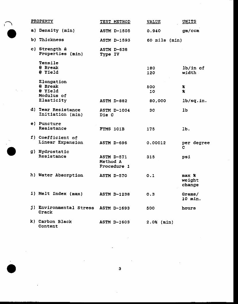
oPROPERTY
a) Densi ty (u in)
b) Thickness
c) Strength &Proper t ies (n ln)
Tensi le0 BreakG Yie ld
Elongation@ Break@ Yle ldModuJ.us ofE las t i c i t y
d) Tear Resl.stanceIn i t i a t i on (n in )
e) PunctureResis tance
f ) Coe f f i c i en t o fLinear Expansion
g) Hydrostat icResistance
h) Water Absorption
X) Mel.t Index (nax)
J) Environmental. StressCrack
k) Carbon BlackContent
TEST METHOD
ASTM D-1505
ASTM D-1593
ASTM D-638Type IV
ASTM D-882
ASTM D-1OO4Die C
FTMS 1O1B
ASTM D-696
ASTM D-571Method AProcedure I
ASTM D-57O
ASTM D-1238
ASIM D-1693
ASTM D-16O3
VALUE UNITS
O.94O gmlccn
60 rn i ls (n in)
o
180120
50010
80 ,00o
30
t75
o . 00012
315
o.1
500
2 .o% (n i n )
lb , / in ofwidth
xxl b l sg . i n .
lb
] b .
per degreec
Ps i
nax Iweightchange
Gramsr/1O n in .
hours
o.3
o
,a 3 .O TNSTALLATTON
3 .2
3 .1 Subgrade p repa ra t ton fo r t he . l each pads and pondsshal.l be undertaken by the contractor who nust insurethat the surfaces to be rined shal. l be snooth and freeof a l l rocksr s tones, s t icks, sharp objects and debr is .The contractor shall cert i fy that the surface on whichthe membrane Ls to be instal led Ls acceptable beforecornmencl,ng work. rnstal lat ion shall be performed underthe dl.rection of a Field Engineer who has instafled am in funum o f 2 , soo ,ooo sgua re f ee t o f HDPE f l ex i b l el ining material, . The Fietd Engineer shall be providedby the contractor, and shall be in abso]ute charge ofthe instal lat ion
To compensa te f o r w r l nk l es , sh r l nkage , / expans ion ,material overlap, Contractor nust indicate at t ime oft ende r i ng a pe rcen tage a l J , owance conpu ted i n h i snater ia l take-of f .
F ie ld Seans
3 .2 .7 fnd i v i dua l pane l s o f HDPE l i ne r na te r i a lshaJ. l be la id out and over lapped pr ior towelding. Extrene care shall be taken by theinstal. ler in the preparation of the areas tobe welded. The atrea to be wel,ded shall bec l eaned and p repa red acco rd , i ng t o t hep rocedu res l a i d down by t he na te r i a lmanufacturer. Al l sheeting shall be wel.dedtogether by an extrusion fusion process or anapp roved equ l va len t me thod . Con t rac to rshall define and detait rnethod used Ln fusionof panels proposed for Liner instal lat ion. Asamp le we l .d sha l l be made by each we lde rprior to conmencernent of f ield weldlng eachday. The weld samples shal l be tested inshear and peel. Two samples mininum shall. betaken durlng each shift .
The welding equipnent used shall be capableo f con t l nuous l y non i to r i ng and con t ro l l l ngthe temperatures in the zone of contact wherethe mach ine i s ac tua l l y f us ing the l l n l ngmaterial, to ensure changes in environraentalcondi t ions wl l . l not a f fect the ln tegr i ty o fthe weld.
3 .2 .2
)
o 4
i - )3 .2 .3 No lf ish nouths" shall be aLlowed within the
sean area. . Where " f ish Douths" occut , thenater la l shal l be cut , over lapped, and anoverlap extrusion weJd shall be applied. Altwelds on cornplet ion of the work shal , l betightly bonded. Any membrane area showinginjury due to excessive scuffJ.ng, puncture,or dlstress from any cause shall be replacedor repaired with an additlonaf piece of tsDPEmembrane at the expense of the Contractor.
The Contractor shall take into account thatrap id wea the r changes a re ve ry poss ib le ,result ing in delays in constructlon of f ieldseams. Fusion of panels and repal rs wi l lonly be permitted under weather condit ionsallowlng such work, and within the warrantylinits inposed by the liner rnanufacturer.
3 .2 .4
4.0 FTELD SEAM TESTING/QUAtITY CONTROL
4 .1 The i ns ta l l e r sha1 l enp loy on -s i t e phys l ca l . non -destructive testing on att welds to ensure watert ighthomogeneous seatns on a continuous basis as instal.lationproceeds. Each seam shall , under the observation ofthe Ownerts Representative, be testeC by vacuun method,swith a nininun vacuurn pressute of 6 psi, by etectr icala rc tes t i ng , o r by an app roved equ iva len t me thod .Visual inspection al.one is unacceptable.
4.2 A Qual i ty-Contro l Technic ian or F ietd Engineer shal . linspect each seam. Any area showing a defect shall bemarked and repaired in accordance with approved IIDPErepair procedures.
4 .3 A t es t we ld t b ree (g ) f ee t l ong f r om each we ld i ngnachine shall be run each day prior to liner welding.The tes t we ld sha l . l be na rked w i th da te , amb ien ttemperature, and wel.ding nachine number. Sanpfes ofthe weld shall . be cut from the test weld and tested inshear and peel. Welds shall have se€rm strength of 90percent of the tensl, le strength of the parent material.PeeJ tes ts sha l . l have a f i l n t ea r ing bond fa i l u re .
. : Seans shall be stronger than the material, . The weldsamp le sha l . l be kep t f o r subsequen t t es t i ng onlaboratory tensometer equipnent ln accordance with theapplicable ASTM standards. Random weld samples nay beremoved f r on t he Lns ta l l , ed we lded shee t . l ng a t afrequency of 1 foot per 5OO l lneal feet of seam andshall be tested ln accordance with the aforementionedprocedures.
o
i
v
o
.o
tsP MINERALS AMERICABARNEYS CANYON PROJECT
. Salt Lake County, Utah
TECHNICAL SPECIFICATION - No: 8?105-02
}TON-$TOVEN GEOTSXTILE I''.ATERIAL
AND
GEOGRID DRATNAGE NETTING
PREPARED BY: A. PAT!{ARDHANMINE AND I ' I ILL ENGfNEERfNG, INC.June 28, 1988
Reviewed: Paul Kaplan - SHB
Robert Parker - BPMA
Zip Zavodni BPMA
Approved:BP Minerals America
t t t lt r r l
t t lt t l
lRev . I
-a REVIEV{eEa 6 ql
No. Date v i s i
ruct ion
3P MINERALS AMERICABAF:NEYS CAt[YoN PROJECTSAtT LAT|E COUNTY, UTAH
rNDEX
GEOTEXTTLE MATERIALSPECTFICATTON FOR NON-WOVENDRAINAGE NETTTNG
SPECIFTCATfON NO: 8?1O5-O2
1.O GENERAL
2.O APPLICABLE SPECIFICATIONS
3.O MATERIAL PROPERTIES
{.O TESTTNG ArO iNSPECTTON
5.O SUBMTITALS
5.O SHIPPING AND UARKTNG
AND GEOGRID
AND REGULATIONS
PAGE
1
1
1
3
4
4
--o
oBP MINERALS AMERICA
BARNEYS CANYON PROJECTSALT LAKE COUNTY, UTAII
SPECIFTCATION FOR NON-WOVEN GEOTEXTTLE. MATERTAL AND GEOGRTDDRATNAGE NETTING
1.O GENERAL
1 .1 Th is spec i f i ca t i on de f i nes the regu l renen ts fo r non -woven geotexti le materiaf, including needled, spun orheat bound, s tap l ,ed, and for geogr id naterJa l .
2.O APPLICABLE SPECTFTCATIONS AND REGULATIONS
2.1 The fo l lowlng publ icat lons of the la test lssue are apar t o f th is speci f icat ion, except where nodi f ied orreplaced by l ,ocal codes or ord l ,nances havlng Jur ls-d i c t i on , i n wh l ch case t he more s t r i ngen t sha l . lgovern.
2 .1 .1 Occupa t iona l Sa fe ty and Hea l th Adn in i s - t ra t i on ,General. fndustry and Health Standards OSHA 22OG129 1910 ) .
2 . t . 2 M ine Sa f e t v and Hea l t h Adn in i s t r a t i on (MSHA) -
Code of Federa l Regru lat ions T i t le 30 (Minera lResources) .
2 .1 .g Amer i can Soc te t y f o r Tes t i ng and Ma te r i aLs(ASrM)
2 . I . 4 FederaL Tes t Me thod S tandards (FTMS) .
2.7.5 Arny Corps of Engineers Test Methods.
2.1.6 AASHTO-AGC-ARTBA-Task force 25
3.0 I,IATERIAL PROPERTTES
3 .1 Ma te r i a l supp l i ed as a geo tex t l t e sha l . l be o f newfirst-quali ty non-eroven (needled, heat of spun bound,o r s t ap led ) po l yne r o f 1OOt po l ye thy lene , lOOSPo lyes te r , l ooS po t yP roPy lene , o ! po l yes te r /Po l yp ropy lene b l . end , des igned and l oanu f ac tu redspecl f ica l ly for the purpose of tens l le re in forcement ,p lanar f low, and f i l t ra t lon. Uater laJ. conposi t ion tobe such as to inhibit deterioration by UV radiatlon.
-a
3.2 Geotext i l .e nater ia l . shaf l be produced so as to be f reeof ho les, undispersed raw mater ia l ,s , broken needl .es, oTany sigm of contamination by foreign Eatter.
3 .3 Geo tex t i Je and geogr id ma te r ia l sha l , J . be un i fo rm incolor , th ickness, s ize, and textufe.
9.4 Geogr id suppl led for use as dra inage net t lng shal l benon-deforned nets constructed of extruded and,/or formedpolyethylene rods. Geogrid sraterlal shal ' l be of new,first quali ty pure low or high density polyethylene, UVs tab i l i zed w i l f r ca rbon b lack . The na te r i a . l may beextended by frothlng with air.
3 .5 The f in ished product shal ] be suppl ied as prefabr icatedro l l s cus tom des igned f , o r t h i s p roJec t so as t on in ln ize f ie ld sea- ing.
3.6 Geotexti le materl.al, supplied shalt meet or exceed thefolJ.owlng tninirlutr standards:
Propertv
Fabric weight D-3776
:( s e e n o t e 3 )
Test Method(see no te 1 )
Units(see Do te 2 )
oz /sq yd 4 . O
Value
8 .0 12 .o
Grab StrengthElongationBurstTrap TearPuncture
D-4632D-4632D-3786D-4533D-3787 (Mod)
coE-cr{o2215D-4491
I lydraulic Properties :
EOS/AOSWater Pern
fbs%
psi1bslbs
sleve sl,zecmlsec
9050
2504570
70-100o.2
18050
42575
130
70 -100o.2
27550
600105140
70-100o.2
-o
3 .8 Geogr id mater ia l suppl iedshal] meet or exceed the
ErgJ:erly
ThicknessWeightSpeci f ic Grav i tyTensil .e strength(mach. . /cross d i rect lon)Elongation @ BreakPoros i tyCarbon BlackMelt Index
Notes:
for use as a hydraulic nediursfol lowi-g rninimurn standards :
Value Un i t s
. 20
.16
.9470 /55
100.80
l2 .o - 3 .o). 26
inches
:: 'pPi
xx
(1) Test nethods are ASTM or Corps of Engineers, asnoCif ied by AASHTO Task Force 25.
(2 ) M in iuun va lues l o t mean rn inus two s tandarddeviations when sarnpled and tested according toAASHTO-AGC-ARTBA-Task Fo rce 25 Reco rn rnendedGuidel ines.
(3) Mlniurun of nachine and cross-nachine direction.
4.O TESTING AND INSPECTION
The suppl ier o f geotext i les used ln th js work shal ltake randon sanples from the roll goods in a quantitysu f f i c i en t t o show comp l , l , ance w i t h t he rna te r i a lproper t ies sect ion of these speci f icat ions. Sanplesshall be tested by a quali f ied laboratory by methodsspec i f i ed i n Sec t i on 3 .O o r we igh t and g rab , t ea r ,burst , and puncture s t rength. Sarnpl ing and test ingshal.l conform to the Reconnended GuideJines of AASHTO-AGC-ARTBA-Task Fo rce 25 . Con t rac to r sha l l subn i tresults of al l testing to Ownerrs Representative.
At t ro l l goods shat l be lnspected on both s ides forunnixed or poorly dispersed ingredients, the Presenceof contaminants or foreigm part icles, broken needles,ho les , o r any o the r de fec t s and a l l de fec t s o rt npu r i t i e s sha l l be removed o r t ePa i red be fo reshipnent .
4.3 A log shall be maintalned of al l , above and addlttonal 'testing performed showing Lot nunber, rol l number, andresu l t s . Th i s l og sha l f be made ava i l ab le t o t heOwner I s Representative.
4 ,7
4.2
-(a
o
5.O SUBMTTTALS
5.1 The fo l l ow lng i t ens w i l l be submi t ted to the Owner t sRepresen ta t i ve fo r app rova l p r i o r t o accep tance o fp roposa l :
5 .1 .1 Samp le o f t he geo tex t i l , e and geog r i dma te r i a l . s show ing seam ing me thods . ( I fapp l l cab le ) .
5 .L .2 De ta i l ed schedu le o f f ab r i ca t i on and ro l lw id th .
5. 1 .3 Shop Drawings showing as a ninlrnum the layoutof the geotexti l ,e system and detai ls of over-l ap , Jo in t i ng and anchorag re me thcds . ( I fapp l i cab le ) .
5 .1 .4 De ta i l s o f r ecommended i ns ta l l a t i onp rocedures , l nc lud ing seaming Ee thods andtenporary anchorage against wind.
5. 1.5 Manufacturer af f idavit that the roaterial. heoffers to furnish wilt meet in e'rery aspectt he regu i re rnen t s se t f o r t h i n t hesespec i f i ca t i ons .
5.2 Pr ior to del ivery of the geotext i l .e or geogr l ,d uater ia lt o t he j ob s i t e , t he f ab r i ca to r sha l , l subn i tcert i f icates of compliance with the geotexti le materialp rope r t i es r egu i remen ts o f t h i s spec i f i ca t i on , f o rconpl iance and acceptance, to the Ownerts Represen-tative
6.0 SHTPPING AND MARKTNG
6.1 Prominent and tndellble marklngs or labeJ,s on each rol lshal, l ldentlfy the manufacturer, rol l number, lengthand wldth of rol l , and rnaterial. thlckness.
6.2 Each rol. l . shall be securely packaged for shlpuent so asto prevent the unraveling of material during handlingand shipping.
-o
BP MINERALS AMERICABARNEYS CANYON PROJECT
Salt Lake County, Utah
TECI:NICAL SPECfFICATfON - No: 87105-03
FTETD QUALITY CONTROL FOR EARTHWORK ANDSLEXTBLE MEMBRANE TTNER (FT''L)
A. PATWARDHANENGINEERING, INC.
Revlewed: Z. Zavodnl - BPMA
Paul. Kapl.an - SHB
R. Parker - BPMA
Approved:BP Minerals America
o
PREPARED BY:MTNE AND MTLLJune 28, 1988
O
t t lt t l
roved
REVIEWDEC 61988
'(ased for t ruc t i
BP MII{ERALS AMERICABARNEYS CANYON PROJECTSALT LAKE COUNTY, UTAH
INDEX
sPECTFTCATTON FOR F rELD QUALTTY CONTROL FORFLEXTBLE MEMBRANE LINER (rur1
SPECfFICATION NO: 8?1OS-O3
1 .O SCOPE
2.O SUBGRADE REQUTREMENTS
3.0 TESTING PROGRAI.{
3 .1 Pe r lod i c Tes ts3.2 Ear thwork3 .3 L ine r Tes t i ng
EARTHWORK AND
PAGE
1
1
1
123
oBP MINERALS AMERICA
BARNEYS CAI{YON PROJECTSALT LAKE COUNTY, UTAH
SPECTFTCATTON FOR FrELD QUALITY CONTROL FOR EARTHWORK ANDTLEXTBtE MEMBRANE LINER (E'Mt)
1 .O SCOPE
In addi t ion to the manufactur ing fac l l l t ies gual l ty contro lprograq, ?s established by the fabricator, a comprehensiveprogram for f ietd guali ty control shall be Provided. Thtsprogram is in contlnuation of and supplements the plants
Progran. All f ield sarnpling and testing shall be done bythe lnstal ler as dlrected by the Ownerrs Representatlve andunder the dlrect supervision of the Ownerts Representative.
SUBGRADE REQUTREUEIrIS
Liner lnstal lat lon shall not begln urt l l the subgrade hasbeen approved by the Ownerrs Representative. The acceptancecr i ter ia shal l be as f o l l ,ows:
The subgrade shal l consis t o f a snooth, un i forn sur facefree of gravel, roots, and other i tens which nay puncturethe l l ne r . Su r f ace roughness l n excess o f L /2 i nch(ve r t i ca f f y ) pe r 2 l nches (ho r i zon ta l ) sha l l no t beal lowed. The sur face of the subgrade shal l be f in ishedro l led wi th a smooth s teel . drum ro l ler .
Al l f i l l placed below a FML and the upper 12 inches in cuta reas sha l l be compac ted t o a t l eas t 95X re l a t i vecompaction, as deternined by the ASTM D155? test nethod.
TESTTNG PROGRAM
The f i e ld i ns ta l l , a t l on tes t p rog ran cons i s t s o f pe r iod l cvtsual. observations, continuity and strength tests.
3 .1 Pe r lod i c Tes ts
These tests are to be nade rout lne ly and are autornat icregardless of the test level 'required. The procedure is asdescribed bel,ow:
2 .O
3 .0
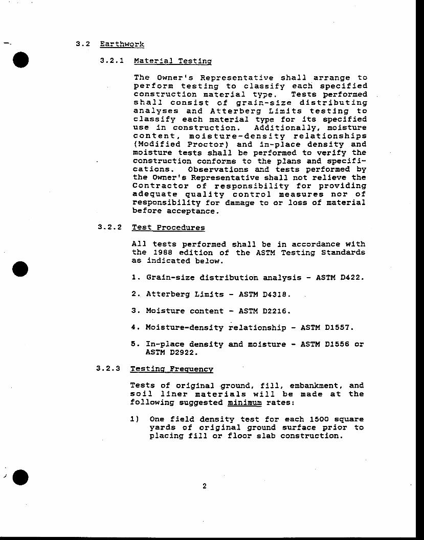
3 .2 Ear thwork
3 .2 .7 Ma te r : a ] Tes t i nq
The Owner r s Rep resen ta t : ve sha l l a r range t ope r fo r ra t es t i ng t o c l ass i f y each spec i f i edcons t ruc t i on na te r ta l t ype . l es t s pe r fo rmedsha l l cons i s t o f g ra i n - s i ze d i s t r i bu t i ngana l . yses and A t t e rbe rg L l n i t s t es t i ng t oc lass i fy each mater ia l type for i ts speci f ieduse i n cons t ruc t l on . Add l t i ona l l y , mo i s tu recon ten t , no i s tu re -dens l t y r e l , a t i onsh ips(Mod i f i ed P roc to r ) and l n -p l ace dens i t y andmoisture tests shall be performed to verify theconstruction conforms to the plans and specif i-cat ions. Observat ions ard tests per forned bythe Ownerrs Representative shall , not rel ieve theCon t rac to r o f r espons lb i l i t y f o r p rov id i ngadegua te qua l i t y con t l o l Deasu res Do r o fresponsibi l l ty for damage to or Loss of materialbefore acceptance.
3 .2 .2 Tes t P rocedures
Al t tests per fornedthe 1988 ed i t i on o fas indicated bel,ow.
shall be in accordance withthe ASTM Testing Standards
1. Grain-size d,istr ibution analysis - ASTM D422.
2. At terberg L in l ts - ASTl . t D4318.
3. Moisture content - ASTM D2276.
4. t ' loisture-density reJ.ationship - ASTM D155?.
5. fn-piace denslty and nolsture - ASTM D1556 olASTM D2922.
3 .2 .3 Tes t i ns F remrencv
Tests of original .ground, f i l . l , embankment, andso i l l i ne r na te r i aJs w i l l be nade a t t hefol lowing suggested minlnurn rates:
1) One f ie ld densi ty test for each 15Oo squareyards of or ig ina l ground sur face pr ior top lac ing f i l l or f loor s lab construct ion.
,a
2) One f i e l , d dens i t y t es t f o r each 5OO cub icyards of f i l l p laced or each layer of f i l lfor each work area, whichever is the greaternunber of tests .
3) One moisture-density cuive for each type ofrna te r i a l used , ES i nd i ca ted by s i eveanalys is and p last ic i ty l ,ndex.
The Owner I s Represen ta t i ve w i l l submi t t heresuJ , t s o f f i e l d dens i t y t es t s r egu i red bythese speci f icat ions,
3 .3 L ine r Tes t i nq
3 .3 .1 F ie l d i ns ta l l a t i on , H€ ld i ng and seam tes t i ngsha l l , be pe r f o rmed unde r t he f u l l t j 'meobse rva t i on o f t he Owner ' s Rep resen ta t l ve .Suspected discrepant areas shatf be ldentif iedwith a contrasting marker.
Des t ruc t i ve shea r anC pee l t es t s sha l l beperforned on fJeld seans every 5O0 l ineaf feetof seam. Actual locat ion of seam tests wi l l berandornly deternined in the f ield by the OwnelrsRepresentat ive. Copies of the resul ts of thesetests shatl be subnitteC to the Contractor andthe Ownerts Representative prior to coverage otthe L iner by over l lner uater ia ls .
The Contractorts inspector shall . mark, log andidentify each type and Jocation of the repair tob€ nade at al l discrepant areas.
The Ownerrs Representative shall have the rightto reject any f iel.d made seam for cause. Causeshall be def ined to incl,ude poor workrnanshlp,de fec t i ve we lds and i nsu f f i c i en t ove r lap o fpanels. Any f, leld uade sean reJected for causesha l l be repa i red o r r ep laced t o t hesat is fact lon of the Owner 's Representat ive.
The en t i re l eng th o f each f i e ld we l .ded seFmsha l l , unde r t he obse rva t i on o f t he Owner r sRepresentative, be tested by vacuum nethods witha uinirnum vacuun ptessure of 6 psi, by electr lcarc testing or by an equivalent nethod approvedby the Ownerrs Representative.
.-o
o3 .3 .2 P rocedure fo r non -pass inq seams
Visually lnspect the entire seam for excessj.veove r lap , poo r sgueeze ou t , w r ink les , o r o the ritens which may indicate poor seam quali ty. f fr up tu re i s Loca ted , pa t ch and re tes t . I fluPture cannot be located v isual l ,y , the leakrnust be isol,ated by sealing port lons of the seaEand repea t i ng t he t es t . A l t e rna t i ve l y , t heen t i r e sea rn can be rewe l ded and re tes ted .Coupon sample and peel test the sean in at l ,eastthree (3) locat ions wi th in the repai red a!ea.
4

APPENDD( G
SEPAGE CAIfI,'IAIIOI{S
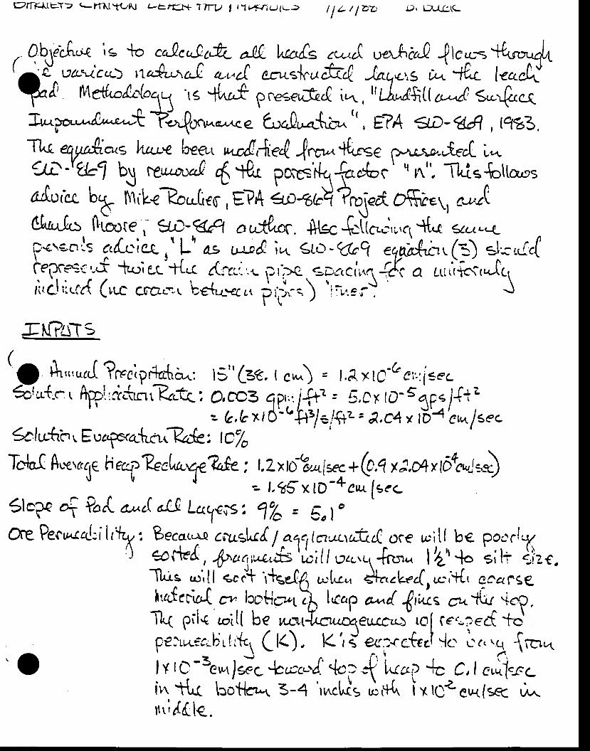
E2rrts{tcY> q-rm.l!N t-E tflr+ ITW t I lrfrrlJ{r> I f L / lbb {). tf,-(c.\c
, Ab,\ecA,N is {o co.Qc,,-Qttc a& t^cofs ,w,A ""rActL
-0lco=+{*rr.rqlttrd^ vaicq-) n,A,,',aL or^cI crr.sjc,, frr!. -tatoc,s ; -+lt lec.fr?f rv\e&.lo(o11 'rE *t^r,f gcese,"fr.e i,,^., l,ri"r+itr u-^/ s-rfzrelr'^M?"{0. w-,<e fuo0.'*-{.-b^ ", E?4 flD- qA, Ftz3 .t,
Tl^r eryali*s h"cwe beo, ,t&,{i.ert {rvr +{r"se r}-Lr-\4-,{rd L*'J.l -'tb'i \ 6,"ru"tr 6 r& potrs'il.q&".t".' * A". TltiE{ottars
c,rotct b,*- iliiL<?o,'ti.cl E?'{ €,o€bq ?q\"rt osi.1 , ,url0[.r.^fu llLrr., W-gA rodoc. S{Ec$t*;,;,,c1 *t.( 3ct.4Dc..go':s c^r0cie ,' L' * .i-p&. i< €Lu'r -q"q eqab!.b. (:) slc ,i,l\Cep,c*':,..f -hc; gq'{< rttl.-,. p r,>g c-DrrCii n", -{i o r,,.,ii,Jc,ri,cl,i.cr{ (r,r- (fi@ca.\ bedr.<cct ptj.-.)
'ilr:eij J
.rtt?a-ts
13" (=6, I e*) = l,l, x rc'G e',-'.i.ecrclirr_c, hirri.rurr Kr.rc:
?f:r,3uffi.t:.T g_:gE i::;r".Scltl-dn r Euagxa{rcr.?ck : tC/o
ll-lc.( ffLsr(({€ h eef ?<rL,t"^qe?ree : t.Zxtrjbort[trc, * b,q y :,*, fch:=J{ -- t.tg x tD -+ ci [se.-Slcpa4?"d. a,uc(aL!Lc\€isz f7o, 5,|"
L
One Pec,r"ctd:ilrlzy: Becot..^l caus[r[. 1a.q",la.-q,-t;.d oce p.it{ be ecc.r!,-t71) €oftrd , $ar1,*,..S 'l;l/
eacrcl +Ro. | 2,', .'l. ei l+ {}.e ,T[^is .^',ll e..1 l+ge04 t-1.,, *fr..Lr4.o.,{, ecarggh,ateda[]k p;lc t.,it( be ru-rtJ,orro.t€u-ccu-> to[ cer,r".t'to*p€)rr.c€ribr{.{ci Ct<) " Ki d qg..ctn.t ..1.. L...g -[*".
o [-ilo;j-aY;"l"ht,li"i-"1t''l*trrri l4le.
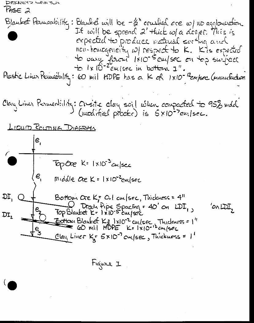
PrrF.l\l\e't> q\u{\Lj.r
?ite. A
€,lar^Letfun'*oh.i{t.: 8..,.*[e{ r"itt tce -ht\ cn J^rd €.ce s.r/ ru"- ^.,.,lo.sra{
o J ll;*|,"*.rJJ:iflY*:k:{ilL:i';trc,i- hn ale',ei\ tcl r=.-;t 4.lr> K. Kti= ex?€ r"['{o oc.,.uK "lo-o^t litr.- s en.lsc &t {ep u.'-)iectc I x ttj
-z"c*igec i^ botla,nt L', .
f \ I | - n , . ,
' ' f r t v b n l - \ > J 7 \ Y t - ' r r v T l L ' & t tl'{aehe L,inr-r /rr,,.rdb,l,\ t (fr n il t1?PE h.es c,. K q( lxro-'zcnlq-(^o^ui'A*
J
ro
DT,
K= lxlD 5cr.. l*c
Cte K= lxlo-zsur(t"c
Claq L,',,-cr ?*.,*.JJ,l;(: O'+r1< eh1 soit Lf,lul,,- ea,,Br,cter|:r qs|vrlrl'' J (r*rt(;{e.J p*"fr.) iE 5 x tol)eu,;!ser-.
I rGu r'ir ?nrsrr tr r-.' TrrAf-Rfft
Dr.
e,
k0e0t,ld(e
Bottor,n Cce Ki o,l c,..fs.c,l1i&es< = 4tl
GE*$* Ym' g ffi'sr- 4D' on Dr''Bb.tef Ka -l xlO-z cut(sec ,
-l'lntd.,^ass ' I "(A nril FDPE (= lxlo''Lcrq(*cLi,aer K; SxtDt cr+lsec, Thiclar^ess = | |
'ou, LDIa
taFt* a
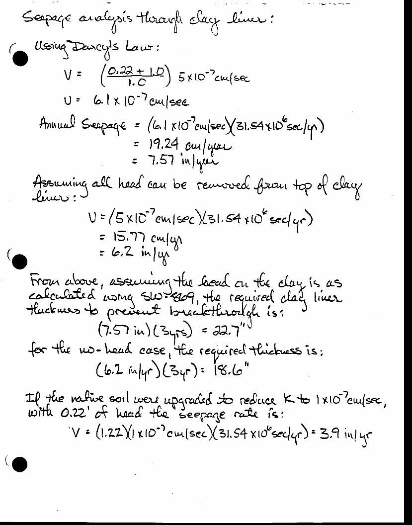
('o
r Ugt',,ta>,Aa.dt l-,'u:'oJ\,,/ = ("#) srto-)e*[s"c
!) : 6. I x t0 -) et*lsee
Snu*J Sqag"1q =
/r;r-tt-,t,l.r,q a-flL-Quno', t J
( 1", t r I ote*r{*.Ya r,s4 ttDbsa/il11,?4.tut1f*-1,51 i^lt*
l^*t c:u^ be rrr,.^.,,"*d Wt].? rt "hV
u = /Sxti7c,*ls.c){er .slrtoa s.()= 15.-l-) c,,^lqn= b,7 i"lT
Rqt^ e.ht te , Lgr urr/;r^.({u Aefcu. {< c/rrq- [q aic$crgrftc"A
'ar-crn( 1Jr)ca"q , ++p ceqai,rec{ l^t t,Lr-
Jt*.I..**o + p*J"^^* t""".A+L-'ry. {. i J(r.n i,^) t31*) = ,a,l" J
+* f{t u,r)- L""d ca:e , \fu reXuireJ ff.LIr..sE -.s I
Lb,L t^ltitgt") . it ,(n"
t{ & *+- eo,[ ryL!^uplc,dcd yo reJ..cr K*o lxto?cu{ser,t l'r'th O,?Z' C l^-artt +0"
o d,..6*5e c"14 ie I
'V s (t.zz{r r rD-)eu-r1se.)(s t.S4 xtou*<llJ = 33 i,tf ,1r
to
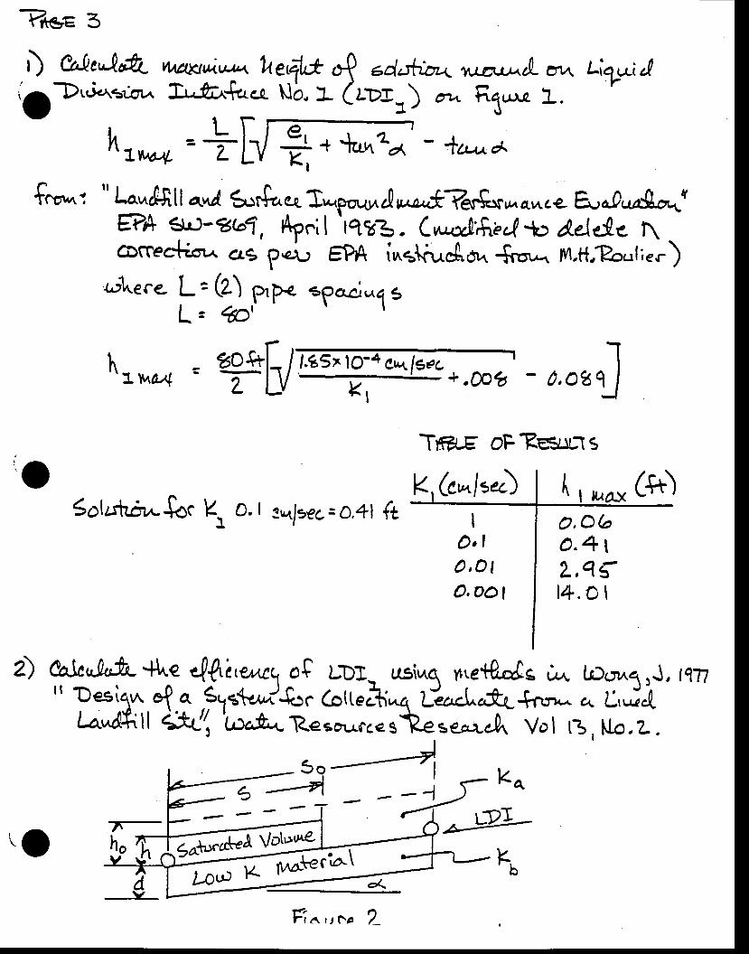
?ttes 3
D &'!e"l,&t- vtaanuv*+ tr"r4* 4 edahbr+ u-o,-ruL or, Liq-*il{ODt.i.a3;ot, !,-fa{t,cl, Nb, I (mf=) oat trX* 1.-
hronr=| - lc,-,^a
$*^': " Lo,,nAtl anl fur$ou* T*p,ooln/r,^r**%F$rc vaawcLfu.0.,Ag-*{Qh sr)- zb1, h"i |
'r??3 . C,"..zjifiar{ t Adege \ -
COCCea*isr,,. 619 p€r.r EPA i"g\n^dr,Jk {,.u1*. ;14,ft,?o,.f;.r)rptuece. L = (Z)
f- : ,*YW egaciul s
htrn* 3 ?h/ 0,oztl.g5>lo'4 ew.ls€c .;;
Kl
Tm-^g oF?suu.ts
Soluhrlw$oc E o. I tulxec= o,4l (t
eak.lttfi.'flne 4,lrle.w\ oS LDJ- usi*q r.etP,-As rr^ l.D.;,^q,J, ri?lf Desilun ef a 3,1rt^,,/f.rc 6ttecti*q t"rs***{nrr^ a. t';iLa"d*ll 1illrtor&*Resa o.o*t"=*J., Vol tj, No .L.
3o--4i ,.I ! rko
o0a{"tWho
Kb
(e*"ltDO,Obo.4 |2-,q{14.ol
<. 1furzl€ctat
tfdv
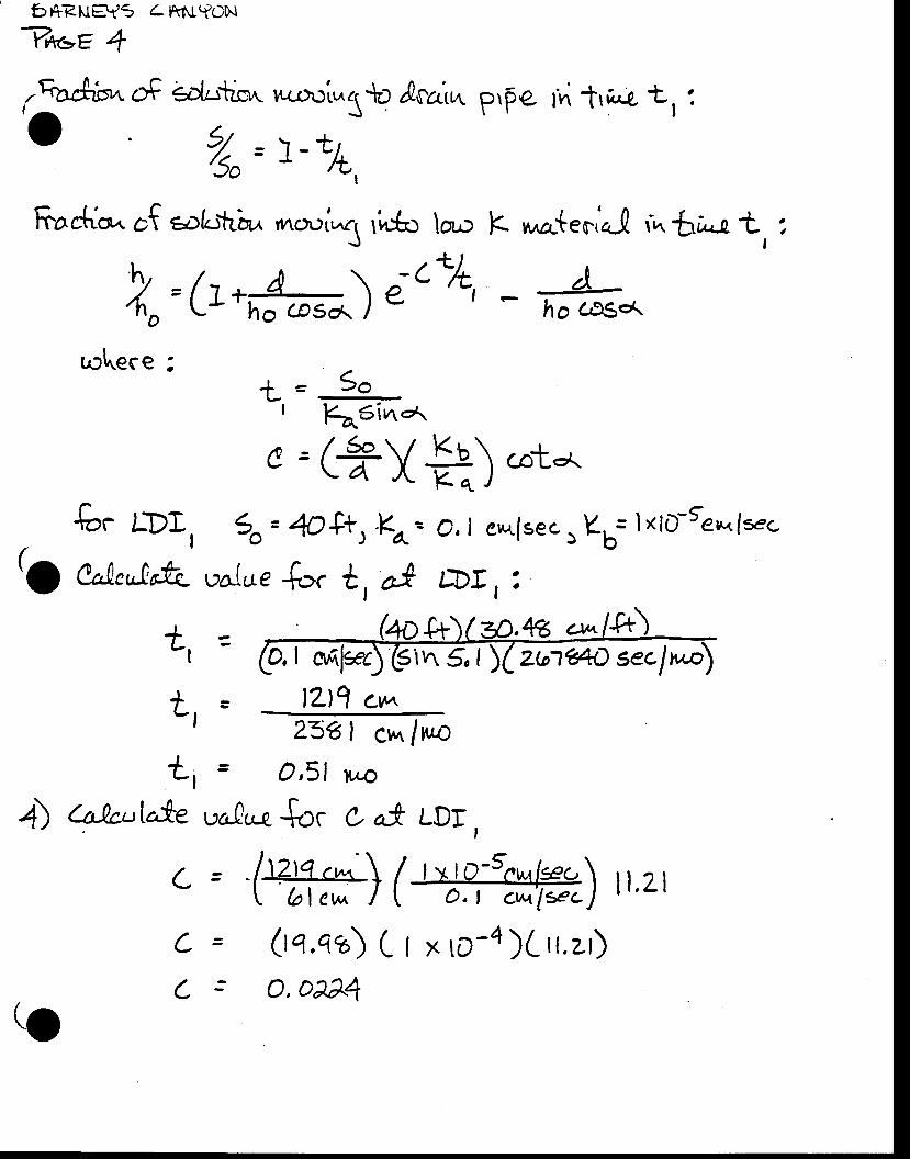
bl+RuryS 4itNYON
V*<=e 4
,%&{swoF €,j,..tc',t r^ro.:l*1to /oaiut p,pe tn tr u,ua. L t io t/ = )-r-i/So r ,L,
Fach*. cf eof.rtrirr. rn o.ri*1 rio*o lao K ,,no-t.a.,o-0 r,^ 6r,-o t, ',
vY=/tna \;c7t, A4o L! 'c -s^ ) e | - T'-o c,rs.<.
t= So' Eo.SivroA,
o=(*-Vb\cot-r.rv 14 ^r l \A, i
fo. LDI , 3o= 4O$t, .f-- o,| ew,.fse.,Kb= IxfD-Sen fsec
(a Colteul&- ua(ue {oc tr aI rDrr :
ohece t
tl
+- f
ti4) (t-Qcutofe
cC
,& r*14o,l anfsec)$rvr 5 | Zb1e4D secln"a
23f.1 cr^r /t,,r:= O '51 rt,o
valu-n-{o. c a-* LDr,
= Er"'s\ / ,"lq-tt'/ft\ p.zlt blew I \ o,t cwt' ls"J I
= (tq.q?) C I x to-4Xrr,zr): O, oe&
lzll cw
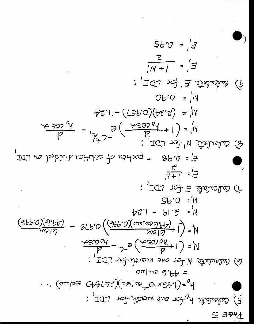
sb,Qz
;N +ll
"'JQ? "+,9'JW?rnOb'Q '= ,'lV
bY'l - (ts ao)@v'v) = irY
Y 'T*?"S-.)='1Y: Tql '$,{ ll:rI'rIW
IIq1 "tp )'rI?.,Y lr:+r"lQe
f r.ryc = ?b,o ='3
" - - l -l{+l -3
: '1e: rt 3 zffinaqgb'o ='N
W'l - bl'€ =1V
sLb,oVoX*r"HWLt) =h
ry- ,_,(Y:s#*r) ='N:' rqt Tr
x:; :: =r voTvDTw
l 4= 1
l -
I -,.= -l
r-
a
Q
o(L
ao
(qav'C(t,rv) _@
. t (c-r lzs TL%)Q*lnanor
xs,t)--rtl
: '1q? -l1f We-vo r?foY Wv?6n (5
9 3+{d_
Or
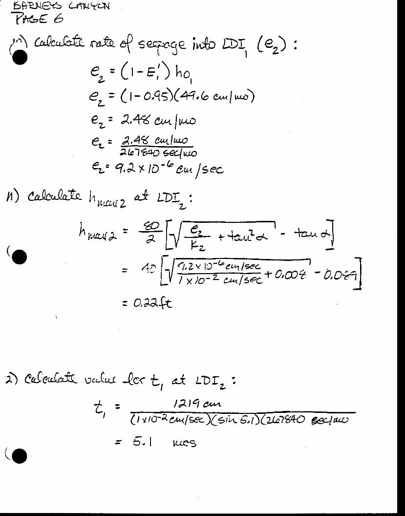
6DRS!.€!5 (-rtruYcx
Vx-e 6
,'A cilct'kfu.O
n) %tkJtIL h w,c*iz 4* lD!r:
r- @-ll , Ihvaa(L = 7bl t tte',,}+'- +,*:l. t t l
= 4a l . l ' t 'zu !)-ecc'1lxc y h ro,L' - . - - - IL1, t*[email protected],@?
-0,Dfi1J
= am+t
{vfq 4 s€'Frte i^{p /El G) :
(r - Fj) ho,(t-o,qs)(4,b o' l*)2,4< oAlv-a
&4< 04lua)2b1?i+O gelLtto
q,Jx /D -o cu, f sec
,o tl d* LDTL'.
la,cl otn.( I v ro-a ou<l *c)( erie, t
o-a
e=L
O=-L
a
cu
{j
,1) CaJc"Glt pc-Qr-(
I -L, -
(o = 5, I u,e3
2Jn1g4O #,lau:
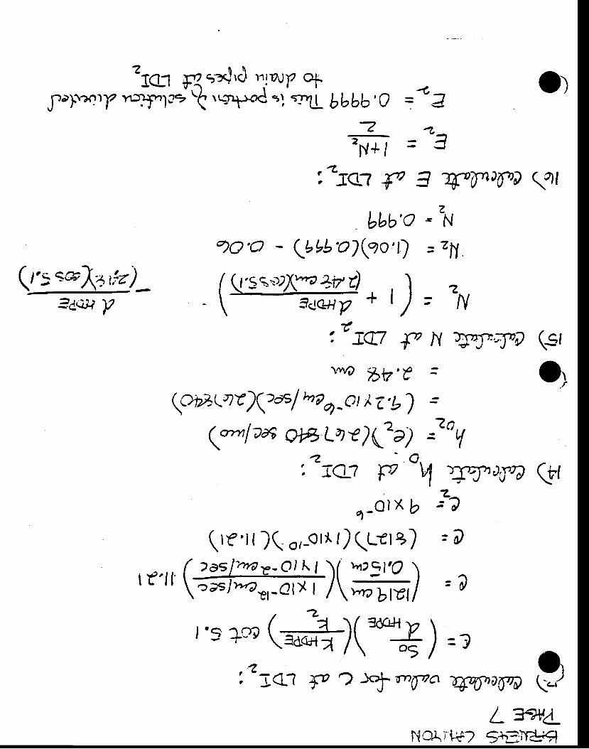
7 $ \'1C:1 flta$tc/ ttlrrJ)z +
J-o).rqry r:t+.'1d't 'q"pod =l''-11 bbbb,O =-- Z-
fr =--ai'rsrl dv A 4.1pa[n (41
bbb'oaO'o lbbb'o)lto't)
,,tj,q7 ry
oY
1-olx b
(,r'r{ )(. o,-orr t) qutr +)
r y.r1 ( '::/-"t-ot I t 11 targt?
)I L rr \E;slrar,-olX | /\r,r"bla/
z€N
= tN.
w),fQ (ffla=Q
=a
L7a/LNclif$? S*El€#l
(Q'sq=uX:o+izr) , , I\ 3ccrrYt* l)= =N
:trq7 f N 51yryl] 'dv' bV,€ =
(cbE( nv)7>csl ,rq-et i.e ,b)
qo,,r I aa afrL? r2(tr) l, V
(st
o;
,.5 an@)(=?):litj< .rt {a
" \l tr7va -rffidayrp
Cq
"cuit Y
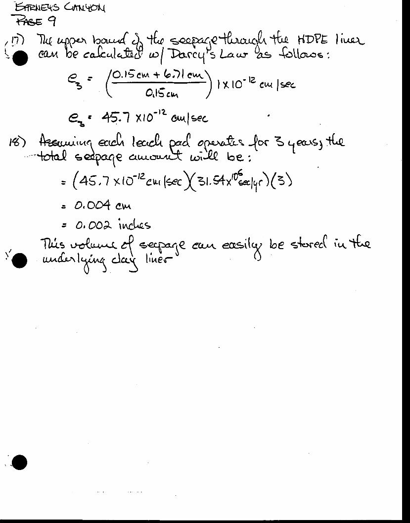
-6er*s Cru\p't.{
?eE 1, n) lk rr{roca lca"A ).. lfu €capar,a{u-,.0, tb, h(t>PE li"q-Ia ae^ Ue .o,.b*1"t8 -/D".l.{Ps l--,^, 0e {>ttr^'" t
o.t5eru + b)la-3-
PG-B
I x lo- tz c* ln.O,l5 crrt
8.1 xlo''t t,f sec
rg) %{rr*i,"tc1 atcla lq',cA yrI agxa"fr* J* 3 1ars3 ttc.
=Ua! edlo1e o,^.*-It ari)& be. :'
= (os,J x tutzcwr {eecX=,. *x'LhJ(s)s D,O4 ev,t
3 O, OOA inclcE
. Tlrr.s .rotr--r a? €€cFa.4q ect*\ ecq-+i[q/ be s{=*".( ;.^ d^e, O un't"t,,l\,{r,u1 .l^\ li,^}.,- $ 0
0) J
,o
t'o
APPEIT{DIX H.1
RECXAMA^TION @ST ESTIMATts SPREADSHEET
('o
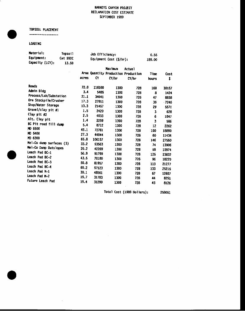
TOPSOIT PLACETIEIIT
LOADIIIG
llaterial: TopsollEqulpnnt: Cat 992CCapaclty (LCY): 13.50
RoadsAdnln BldgPrccess/Lab/Substat lon(he Stockpile/CrusherShop/Hater StorageGravel/clay plt tfClay plt f2Al t . Clay p l tBC Plt road fl l l dunpilD 6500ilD 6400lrD 6300tlel-Co dunp surfaces (3)llel-Co Ounp 0utslopesLeach Pad BC-lLeach Pad BC-2Leach Pad BC-3Leach Pad BC-4Leach Pad il-tLeach Pad il-2Future Leach pad
EARIIEYS CA'IYOII PROJECTRECLA}TATIOII COST ESTIIT'IATE
SEPTEI{BER 1989
Job Efflciency;Equlpmnt Cost (g/hr):
0.56189.00
llaxlm,rm ActualArea Quantlty Productlon productlon Tlre
acnes CY C'tlhr Cy/hr hours
728 160728 8728 47728 38728 29728 3728 6728 3728 t2728 100728 60728 146728 74728 58728 126728 96728 113728 133728 67728 U728 43
Costt
30157142488387246557t628
tM7586
2262r8890rr43427560139061097{2fi3218220212772521512607825r8r26
258051
72.0 116160 13003.4 5485 1300
zt.t 34041 1300r7.3 27911 1300r3.3 2t457 1300r.5 2420 13002.5 4033 13001.4 2259 13005.4 87t2 1300
45.1 72761 130027.3 44044 130065.8 106157 130033.2 53s63 130026.2 42269 130056.9 91799 130043.5 70180 130050.8 81957 130060.2 97123 130030.1 {8561 130019.7 31783 130019.4 31299 1300
Iotal Cost (1989 Dollars):
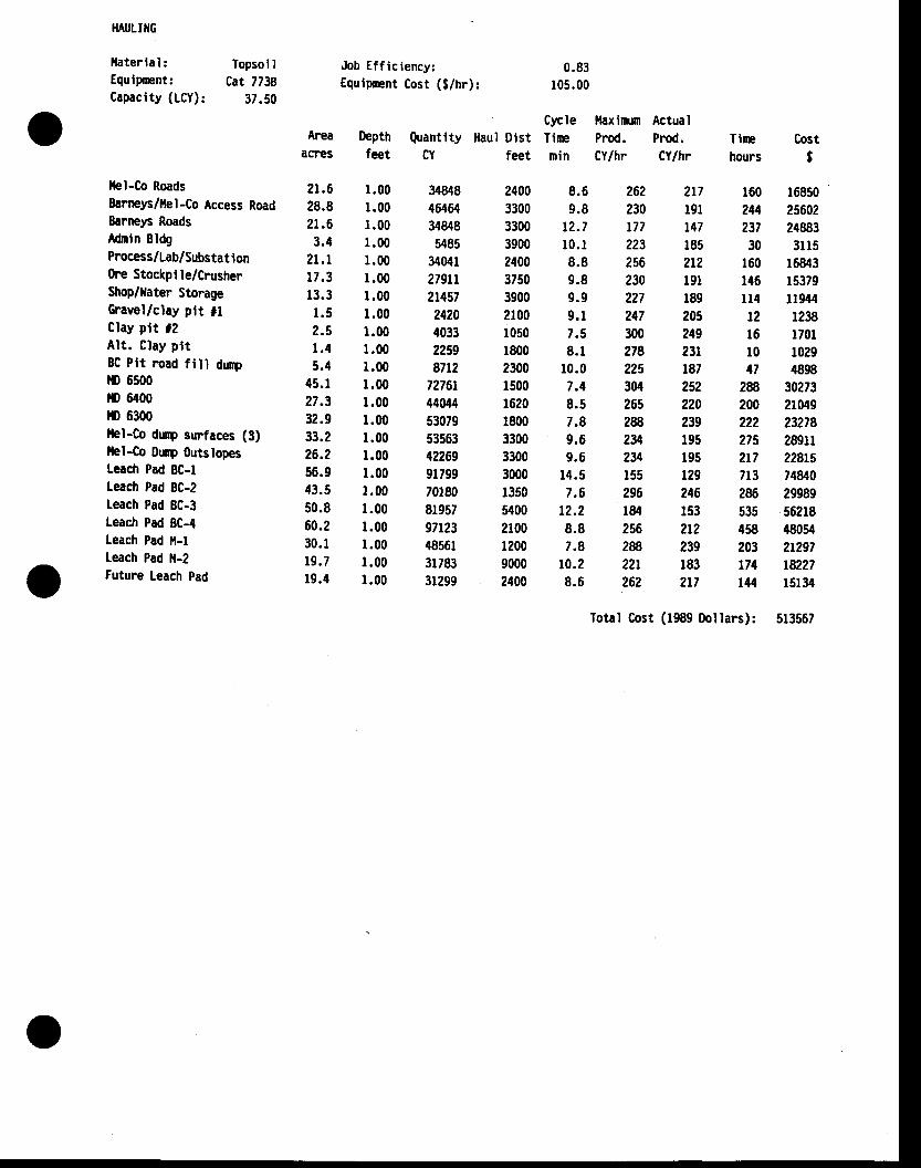
}IAULTIIG
llaterlal: Topsol IEqulpmnt: Cat 7738Capacity (LCY): 37.50
llel-Co RoadsSarneys/tlel -Co Access Road8arrcp RoadsAdnln EldgProcess/Lab/ Substat I on(he Stockpl le/CrusherShop/llater StorageGravel/clay plt flClay plt f2Alt . Clay ptt8C Plt road fill rtrrylrD 6500lrD 6400ro 6300llel-Co dunp surfaces (3)llel-Co Dnnp OutslopesLeach Pad BC-lLeach Pad BC-2Leach Pad BC-3Leach Pad 8C-4Leach Pad l,l-lleach Pad ll-2Future Leach Pad
Job Efficiency:Equlpnent Cost (g/hr):
0.83105.00
Areaactes
2r .6 1 .0028.8 1.002r .6 1 .003.4 1 .00
21.1 1 .0017.3 1 .0013.3 1.001.5 1 .002.5 1 .001.4 1 .005.4 r .00
45.1 1 .0027.3 1.0032.9 r.0033.2 1.0026.2 1.0056.9 1.0043.5 1.0050.8 1.0060.2 r .0030.1 1.00r9 .7 1 .0019.4 1 .00
34848 240046464 330034848 33005485 3900
34041 240027911 375021457 39002420 21004033 1050z?59 18008712 2300
72761 150044044 162053079 180053563 330042269 330091799 300070180 135081957 540097t23 210048561 120031783 900031299 2400
8.6 2629.8 230
t2.7 L7t10.1 2238.8 2569.8 2309.9 2279.1 2477.5 3008.1 278
10.0 2257.4 3048.5 2657.8 2889.6 2y9.6 234
14.5 1557.6 296
t2.2 1848.8 2567.8 28
10.2 22r8.6 262
Tlm Costhours t
160 16850244 25602237 2488330 3U5
t60 16843146 15379u4 1t94412 123816 1701l0 102947 4898
28 30273200 21049222 23278275 289112t7 22815713 7{840zffi 29989535 56218458 48054203 21297174 ta27144 15134
Cycle ilaxim,m ActualDepth Quantlty ]taul Dist Tirc Prod. prod.feet CY feet min Cy/hr Cylhr
217r9l147r8521219118920524923r187252220239195195r292461532r2239r832r7
Total Cost (1989 Dollars): 513567
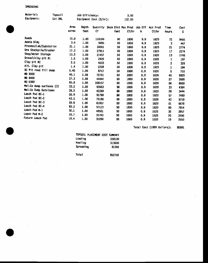
SPREADIIIG
llaterial:Equlprent:
Topsoi ICat D8L
Job Efficiency:Egulpmnt Cost (f/hr):
0.90r32.00
Areaacnes
Oepthfeet
Quantity Doze Dlst tlax Prrod Job Eff Act Prod TinpCY feet CY/hr t CY/hr hours
Costt
RoadsAdmin BldgProcess /Lab/Substat i onOre Stockpi le/CrusherShop/llater StorageGravel/clay ptt t lClay plt f2Al t . Clay pt tBC Ptt road ft l l dunpI'O 6500tI) 6400ilD 6300llel-Co dunp surfaces (3)llel-Co ounp 0utslopesLeach Pad BC-lLeach Pad 8C-2Leach Pad BC-3Leach Pad BC-4leach Pad ]l-lLeach Pad l,l-2Future Leach pad
72.0 1.003.4 1.00
zt.t 1.0017.3 r .0013.3 r .001 . 5 1 . 0 02.5 1 .001.4 1 .00
5.40 1.0045.1 1 .0027.3 r .0065.8 r .0033.2 1.0026.2 1.0056.9 1.0043.5 r .0050.8 1.0060.2 1.0030.r 1.0019.7 1 .0019.4 r .00
1800 0.91800 0.91800 0.91800 0.91800 0.91800 0.91800 0.91800 0.91800 0.91800 0.91800 0.91800 0.91800 0.91800 0.91800 0.91800 0.91800 0.91800 0.91800 0.91800 0.91800 0.9
1161605485
3404r279172t4572420403322598712
7276t44044
106157535631226991799701808r95797r23485613178331299
16201620r62016201620r6201620t62016201620r62016201620162016201620r62016201620r620r620
505050505050505050505050505050505050505050
72 94653 447
2t 2174t7 227413 1748I 1972 329I 1845 710
45 592927 358966 865033 436426 344{57 74W43 571851 667860 791430 395720 2s9019 2ss0
Total Cost (1989 Dollars): 80991
TOPSOIL PTACE}IEIIT COST SUiI}IARYLoadingHaul irySpreading
Total
25810051360081000
8s2700
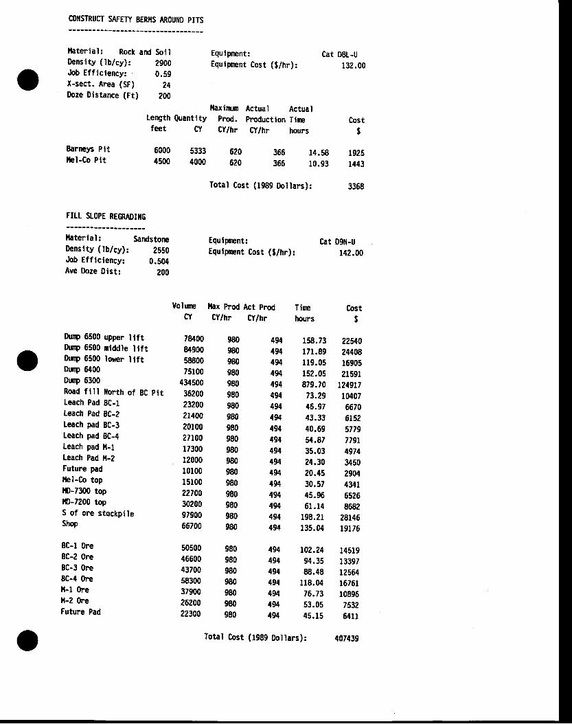
COflSTRUCT SAFETY 8ER}IS AROUIID PITS
llaterial: RockDenslty (lb/cy):Job Efflclency:X-sect. Area (SF)Doze Distance (Ft)
Earne)6 Pltllel-Co Plt
Equipmnt:Equipnnt Cost (g/hr):
Total Cost
Cat D8L-U132.00
Costt
and Soil29000.59
24200
llaxinrun Actual ActualLength Quantity prod. production Tirefeet CY Cy/hr Ct/hr hours
60004500
53334000
620620
366 14.58 1925366 10.93 1443
(1989 Oollars): 3368
FILI SLOPE REMruIilG
lhterlal: SardstoneDenslty (lb/cy): 2550Job Efficiency: 0.504Ave Doze Dist: 200
Equipmnt:Equlpnent Cost (l/hr):
Cat 091r|-U1{2.00
Tirn Costhours $
Uolurc llax prod Act prodCr CY/hr Cy/hr
thry 6500 upper ilftDurp 6500 mtddle llftOunp 6500 lorer ltftDup 6400Dunp 6300Road fll l i lorth of BC pttLeach Pad BC-lteach Pad 8C-2Leach pad BC-3Leach pad BC-4Leach pad il-lLeach Pad il-2Futune padllel-Co top10-7300 topf0-7200 topS of ore stockpileShop
8C-l Ore8C-2 OreBC-3 Ore8C-4 (heil-f Orell-2 (heFuture Pad
78400 98084900 98058800 98075100 980
434s00 98036200 98023200 98021400 98020100 98027100 98017300 98012000 98010100 98015100 98022700 98030200 98097900 98066700 980
50500 98046600 98043700 980s8300 98037900 98026200 98022300 980
Total Cost
494 158.73 22il0494 171.89 24408494 U9.05 16905494 152.05 21591494 879.70 1249t7494 73.29 10407494 46.97 6670494 43.33 6152494 40.69 5779494 54.87 779r494 35.03 4974{94 24.30 3450494 20.45 2904494 30.57 4341494 45.96 6526494 61.14 8682494 198.21 28146494 135.04 19176
494 102.24 14519494 94.35 13397494 88.48 12564494 118.04 1676r494 76.73 10896494 53.05 7532494 45.15 641r
(1989 Dollars): 407439
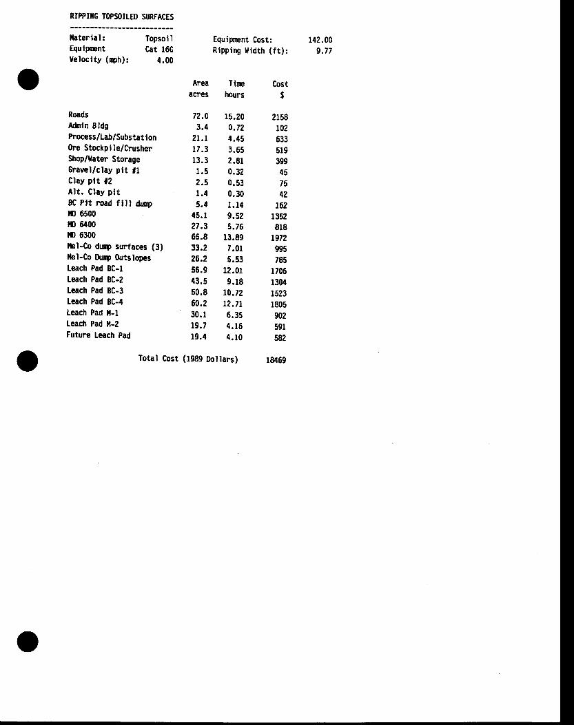
RIPPIIIG TOPSOILED SURFACES
l laterlal:EqulpmntVeloclty (ryh):
Topsol ICat l6G
4.00
Equipnent Cost: f42.00Rlppi rq l l id th ( f t ) : 9 .77
RoadsAfiln BldgPrccess/Lab/Substat I onOrc Stockplle/CrusherShop/llater StorageGravel/clay ptt flClay plt 12Alt . Clay pl t8C Ptt mad fll l dr4r{) 6500lrD 6400l,D 6300flel-Co dunp surfaces (3)llel-Co Dunp OutslopesLeach Pad BC-lLeach Pad 8C-2Leach Pad BC-3leach Pad BC-4Leach Pad ll-lLeach Pad ll-2Future Leach Pad
Areaacres
72.03.4
21 .117.313.31 . 52.st .45.4
45.127.365.833.226.2s6.943.550.860.230. I19 . 719.4
Tlrchours
r5.200.724.453.652.810.320.530.30l . t49.525.76
13.897.0r5.53
12 .0r9 . r8
r0.72t2.7t6 .35t l . l64 . 1 0
Cost$
2r58t02633519399457542
t62r352818
t972995785
170613041523180590259r582
r8469Total Cost (f989 Dollars)
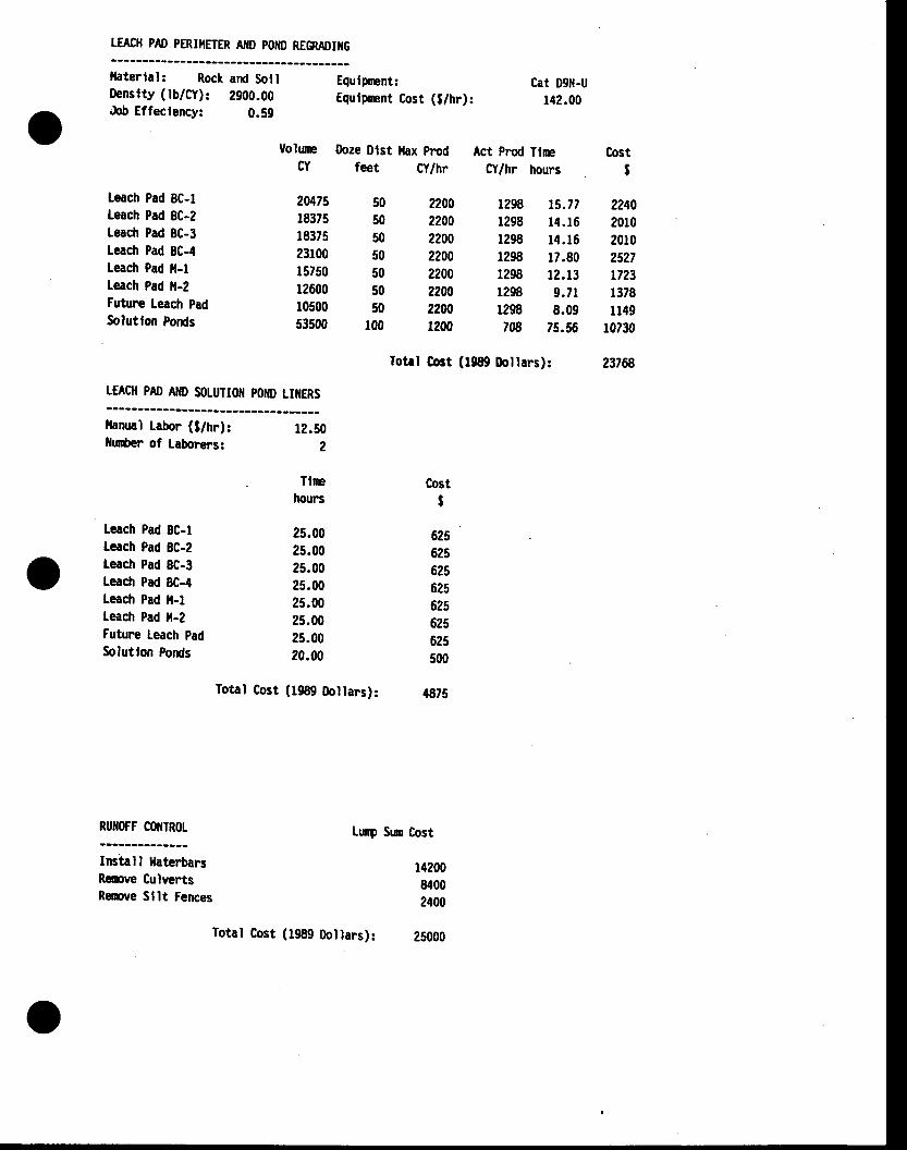
TEACH PAD PERIIIETER A'tD POIID REGRAOIIIG
llaterlal: Rock and SollDenslty (lb/Cy): 2900.00&b Effeclency: 0.59
Equlpmnt:Equlpmnt Cost (g/hr):
Cat 09il-Ur42.00
Volurp Doze Dlst llax prodCY feet Cy/hr
Act Prod TlrnC'Y/hr hours
Cost$
Leach Pad 8C-1teach Pad 8C-2Leach Pad 8C-3Leach Pad BC-4Leach Pad ll-1teach Pad it-2Futune Leach PadSolutlon Ponds
20p.75 5018375 5018375 5023100 5015750 5012600 5010500 5053500 100
1298 t5.77 22401298 14.16 20101298 14.16 20101298 U.80 25271298 12.13 n231298 9.7r 13781298 8.09 114978 75.56 10730
2200220022002200220022002200tzo0
Totrl Gost (1989 Dollars): 23768
LEACII PAD AIIO SOLUTIOII POIIO LI]IERS
lhnual Labor (l/trr):llu$er of Laborers:
Leach Pad BC-lteach Pad 8C-2leach Pad 8C-3Leach Pad 8C-4leach Pad ]t-1Leach Pad il-2Futurne Leach pad
Solutlon Ponds
RUIIOFF COIIIROL
lnstall lfaterbarsRemve CulvertsRemve Sllt Fences
Total Cost (1989 Doltars): {875
Lrq Srn Cost
12.502
Tlrehours
25.0025.0025.0025.0025.0025.0025.0020.00
Cost$
625625625625625625625500
1420084002400
Total Cost (1989 Dollars): 25000
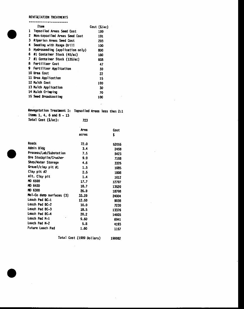
REVEGETAT IOII IREAAEilTS
ItemI lopsotled Areas Seed Cost2 llon-topsolled Areas Seed Cost3 Rlparlan Areas Seed Cost4 Seedlng wlth Range Drill5 lltdroseeClry (appllcation only)6 fl Contatner Stock (aslac)7 fl Contalner Stock (f35/ac)8 Fertlllzer Cost9 Fertll lzer Appllcatlonl0 Urea Costll Urea Appltcatlon12 llulch Cost13 llulch Appllcattonl{ llulch Crlnplngf5 Seed Broadcasilng
Reuegetatlon Treamnt I:Iteus l. 4. 6 and I - t3Total Cost ($/ac):
Topsolled fteas less than 2:l
723
Cost (g/ac)199l9l203100800180608473022l5
1003070
100
Ar€aacres
72.03.47 . 59 .94 . 61 . 52 . 51 . 4
t7.718.726.0
33.2012.5010.018.520.29.605.8
1 .60
520562458il237158332610851808t0l2
t2797r3520187982400490:t87230
r$76l/t605694r41931157
199982
CostI
RoadsMmln BldgProcess/Lab/Substat i on(he Stockpile/CrusherShop/tfater StorageGravel/clay ptt llClay plt f2Alt . Clay pl tto 6500lD 6400rt) 6300thl-Co dunp surfaces (3)Leach Pad 8C-lLeach Pad BC-ZLeach Pad BC-3Leach Pad BC-4Leach Pad it-lLeach Pad ll-2Futune Leach Pad
Total Cost (1989 Doltars)
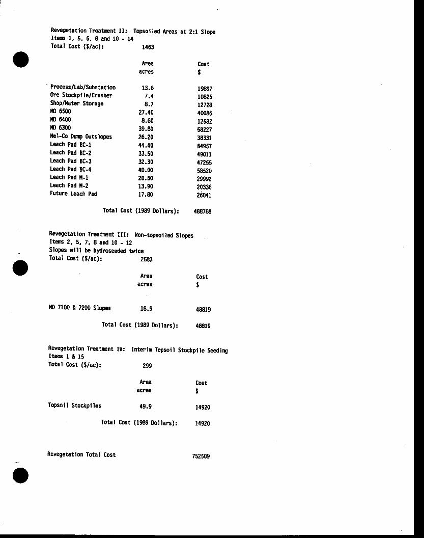
Revegetatlon Trcatrnt II: Topsolled Ar€as at 2:1 SlopeItem l. 5. 6. 8 and l0 - l{Total Cost ($/ac): 1463
ft=aacres
13.67 .48 .7
27,408.60
39.8026.2044.f033.5032.3040.0020.5013.9017.80
r9897r0826t2728400861258258,2273833164957490114725558520299922033626041
488788
Cost$
Total Cost (1989 Doltars):
Revegetatlon Treatnent III: llon-topsol led SlopesIters 2. 5, l. 8 and t0 - 12Slopes rlll be hydroseeded twlceTotal Cost ($/ac): ZS83
Process /[ab/Substat I on(he Stockplle/CrusherShop/Iater Storagero 6500!I) 6400r|) 6300]lel-Co Durp 0utslopesLeach Pad 8C-tLeach Pad 8C-2Leach Pad BC-3Leach Pad BC-4Leach Pad il-lLeach Pad ll-2Future Leach pad
lD 7100 & 7200 Slopes
Revegetation Treatrcnt IU:IteG I t 15Total Cost ($/ac):
Topsoll Stockptles
Areaacnes
r8.9
Total Cost (1989 0ollars):
AreaacFes
49.9
Total Cost (1989 tloilars):
Interlm Topsoil Stockpile Seeding
299
o Cost$
48819
48819
Cost$
14920
14920
oRevegetation Total Cost 752509
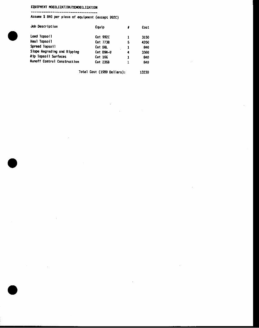
EQUIPT|EilT fioEIrIZATIot{/DEtoEILIZATI0ll
Assnnp $ 840 per plece of eguiprcnt (except 992C)
Job lbscrlption
Load Topsoilllaul lopsoilSpread TopsollSlope Regradtry and RippirBRlp Topsoll SurfacesRumff Control Construction
Cat 992C ICat 7738 5Cat D8L ICat 09il-U 4Cat l6G ICat 2358 I
Equip
31504200840
3360840840
Iotal Cost (1989 Dollars):
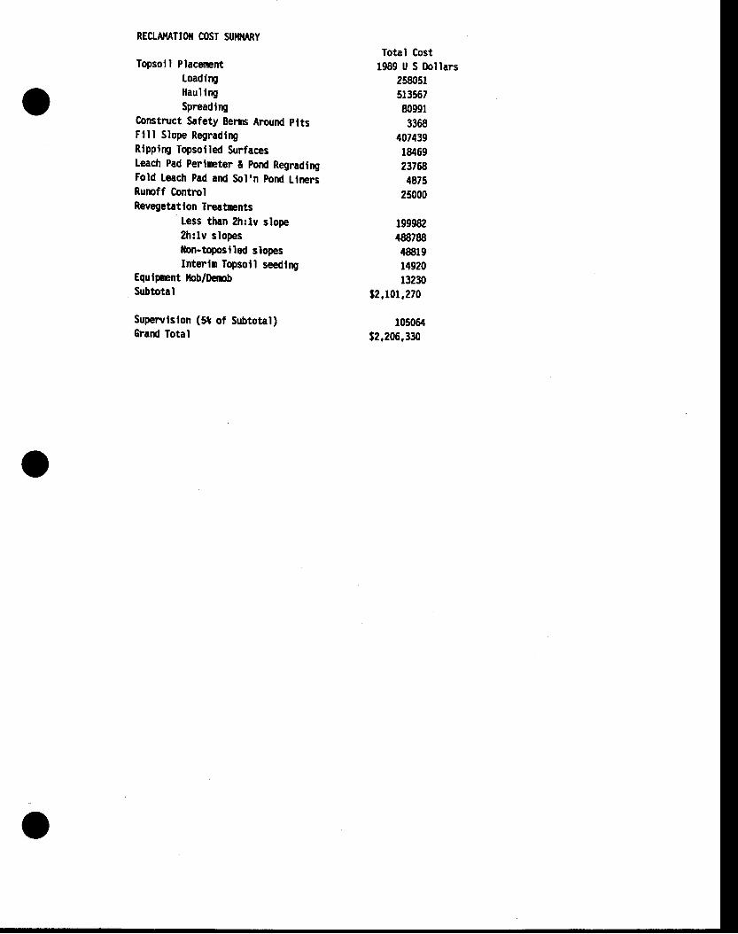
RECLA}IATIOII COST SUISIARY
Topsoll PlacemntLoadlryHaul l rySpreadtry
Construct Safety Eems Around pltsFlll Slope RegradlngRlppirp Topsoi led SurfacesLeach Pad Perlnpter t pod RegradtngFold leach Pad and Sol'n pond LlnersRumff ControlRevegetatlon Trcaftnts
Less than 2h:lv slope2h:lv slopesllon-toposlled slopesInterln Topsoll seedlry
Equlpmnt llob/DembSubtotal
Supewlslon (tt of Subtotal)Grard Total
Iotrl cost1989 U S Dollars
258051513567809913368
407439r8469237ffi4875
25000
1999824887884881914920r3230
s2.101.270
r05064t2.206,330
o
I
-v
APFEIITDIXH.2
R,ECXATII^TION @ST ESTIMATts ASST'MPNONS
(
o
t'o
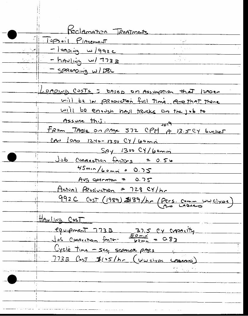
-o\ * , / 9o tZ C-
.'1_ 1]l_e_L
w"t I b e, tF, PR "o-rgtlor. Svtl t1t; fi-a th+1- th€-rLi i
. i , ls, I I ba e"t"r"t" htUi tfe.r.k< o,-, troJ.b to
5?z e
= 1J . Sr "
9S^n ,n /Lo* ,
€ralToa
, ; Oo': r r"C C.sf Cgg:t) frB"t. /h. (?ers. c.=:=__r,rpclyoc)Lfi-o Lne,r6-el -/
' r n' {le,Na I ftsctv.t\on a ') z3 QY / h'.-
l lZg C-t-r f i /oS/h- Gu.rcr,e. t r to, .rr*c)
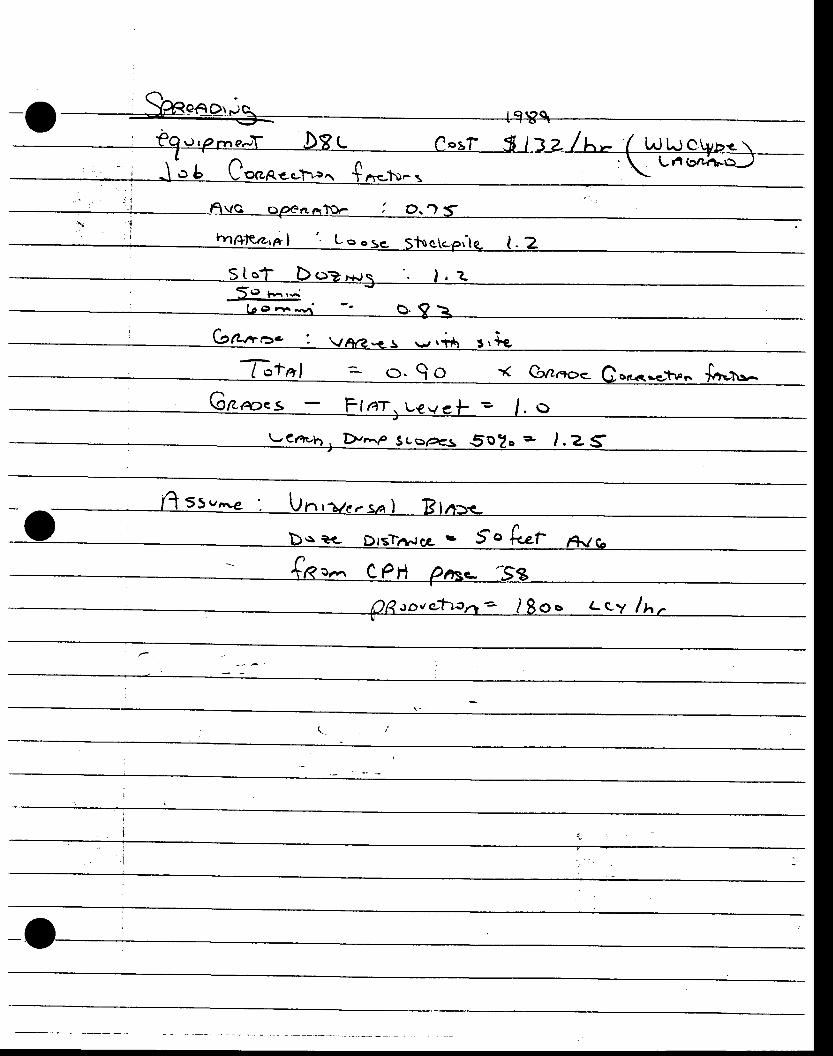
-o
o1L -zr' O
%t,al =_o. go d Gnnoe Co,.,,<..,1.".. fr-r.^/-\oBoes - Ff at . uevef e l . o
DnP 3e opgs 5o?o - l .Z
QRtoue. t - : r .n ' - )8o" Lc-v lx rU
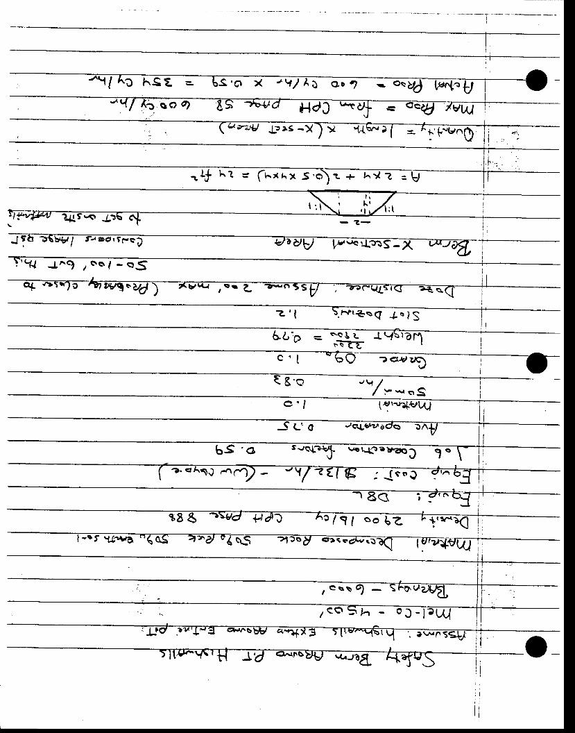
C hSZ e S 'O X "1 / A l o r ?
HarJr-A laeS -Xl ><
vw) l i.'F*trnQ
q{t<r J
-. t tat l t-S? .,,c lt36S _
? J^9 r ss , - s j i
z ' l . r i t t < . s ( + " tg
5tb = sQ U L -L V\lam" : :E t
c' t
E'o
? A-t/UD
' t \ // :- *, etS
t&,\.r"F.rW
bS 'o s-/<rtauJ:
c/ l f oob! '
,Q= \1 -
z ca 5, .
o_
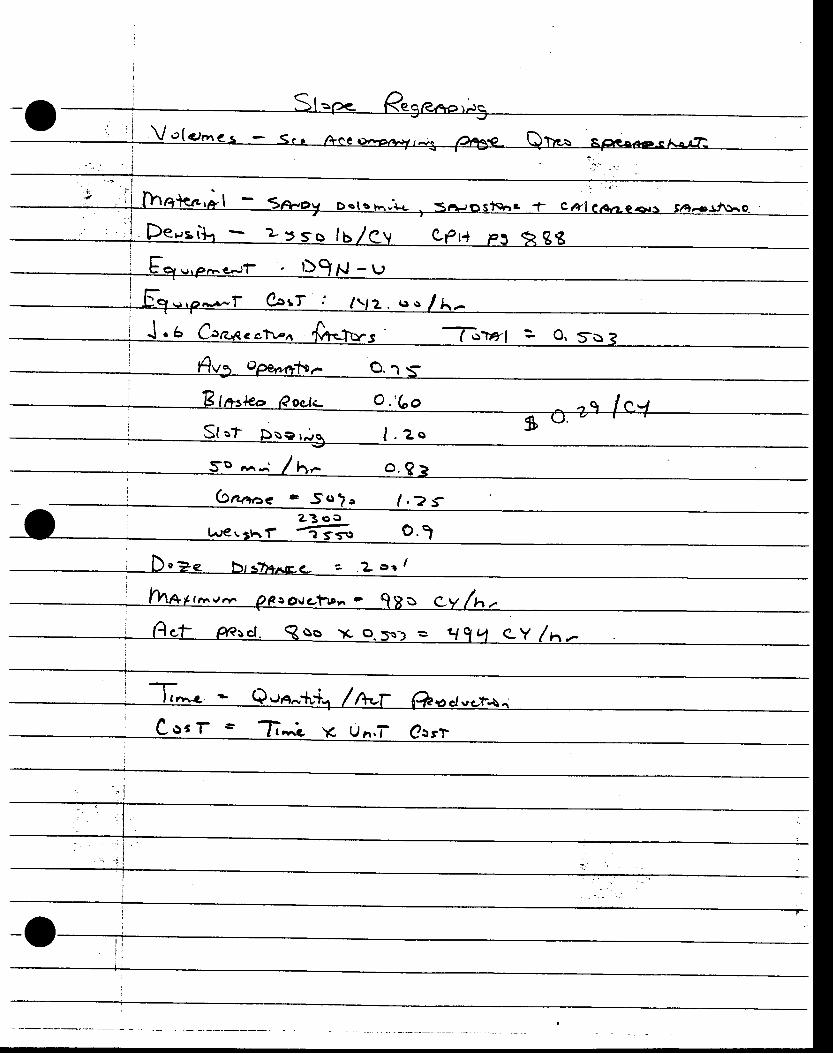
r '+n - 25so ls
i ', 1 , / t ni J . 5 LbR,qe ctr.'n 'f,n<Iq.S '
Ji)Trrf = O. S:o a-I' . t1
Chnoe - 5o?o / . ? t
Ls€s;trf €s,
, l \ /l
' h4r+rar-.,r,- pF.o,rc.trrr. ' gFo gy 4r.;i Act ffrcj. R ss rc o. so: = at 1 q C-Y /h.-I-i
; C oe r t fl; \c U n,T' @rrl
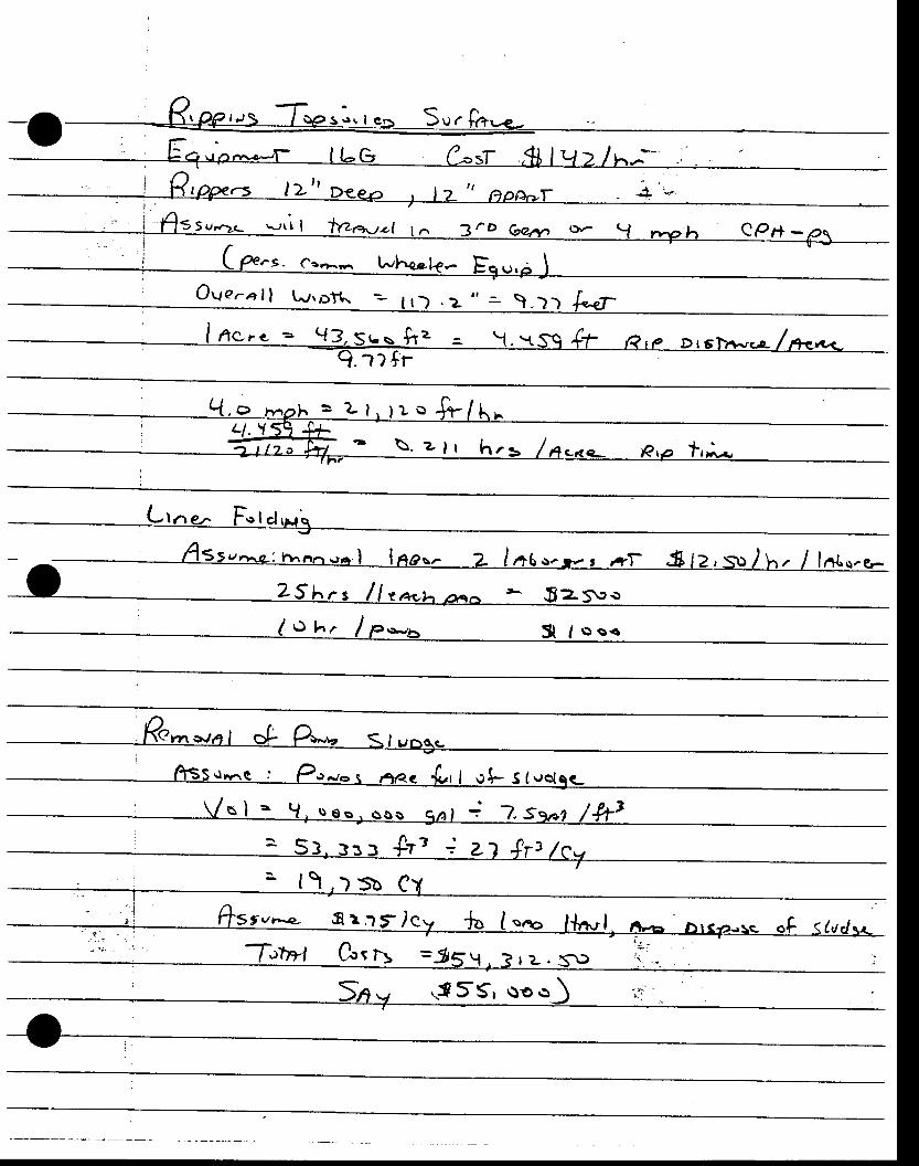
r )€-^
v
1 O r r l r - . r - t t
- i 1455v,2q ,- l t l t ta, ,q.-rz. l r^ -ro Gar,- r : , r ( .J ----u eOrr-==
. : Assr " . ,c - :n^a, - . ro . l Inao. - 2- /a6o. . - r ,+ l - .$12,S: /hr / ln t ,o .e-\
(-(ernwal oL P*ro qlvog.-
, I
- f , , )5b C
s rvr-.e.- s r .r E&v -ht I "^o l+,.b., I
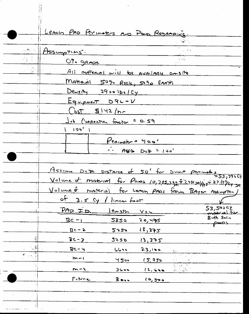
De*" 29oo lbs /C
Eo, b9t - -V
| ' o o l I
o. 5ol
,^a l t r= t l ss '
ftUe-
f t t ,-
ol u,-'e- rf t'v'tr+*rtg1 -R.
ol r *& tgrra\ &.
"l 3. { Cy / 1,.,...- {.-r
=_S:le?-f-ctizz
"? tlSS
53rsot '
?c - : l ) . 3?
n r - l
ZJ , t o s
f 5. +tb
lna -'L ( L , ( t r
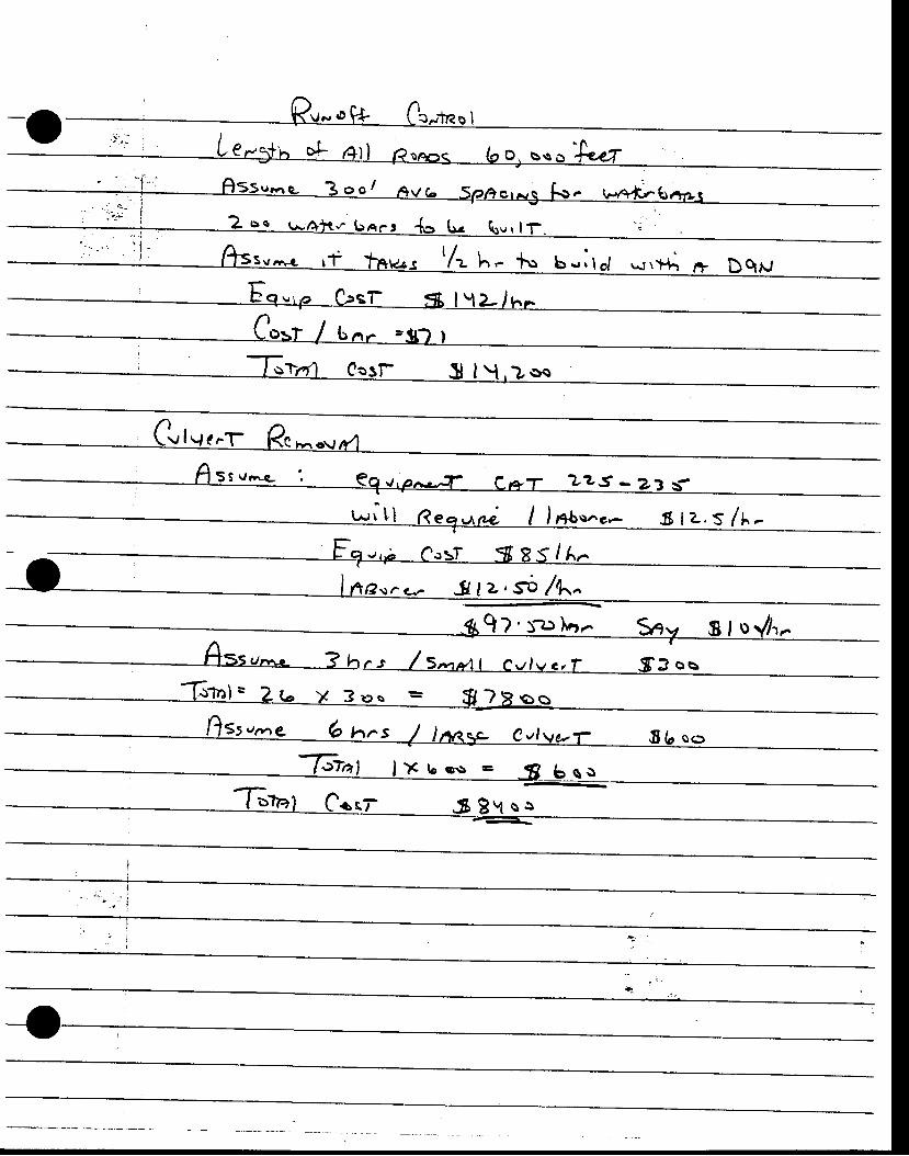
n t .
a_t
+5 ss
t o-t C..t g
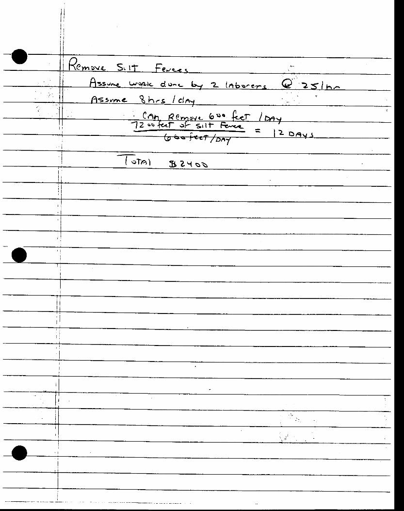
I
III
:
-oLrrotZlc d o-t-
evn t l Rh-s l c l
.c-?z
"o
/^'s -e f3 € 2 :s ln - .
flr,"r $ Zv ss
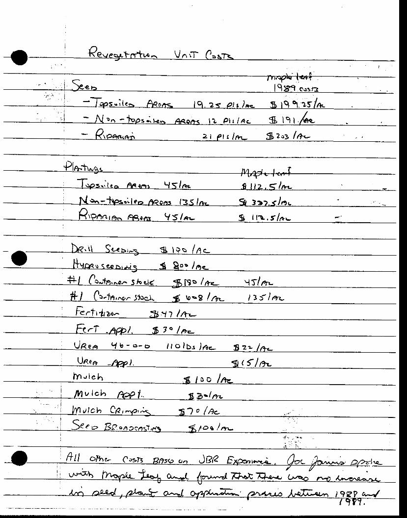
' - i A r - {. . , r -Non- ' fops . , te . .4cor+< l zp t r /ac $ lg l .:
r't. - Ktoe*,+i zt et s lrr- fllo> lrl- . . _
r r, l \ps . . le^ raqr-n t {S/ r* . , f l l z .< / r r . - _
Ne ' . -+ps. ' ,1?- r *? .o , rs l35 /n- g33?. .< /a . : - ._
Rrprrara,^ Re,e,^r. V5/*- g ttt,f/a-. --
, Ne.\ \ Srx>,rs $ Ies /nc_-O----l ,nr*o.*^, ., u *o. r"-
*f l Cr-tn,^a.^Shc.i< g, lg>/ry.- ! f /ag
.ln,*.J1'ocj. 4 toog ln- l3{lar-
. l - t rT -nft | . f i7"/a._URea 1b-o-o l to lbs)a+ f rz - / r+_
t' ftll otlu C*n BlTso ct., Jge
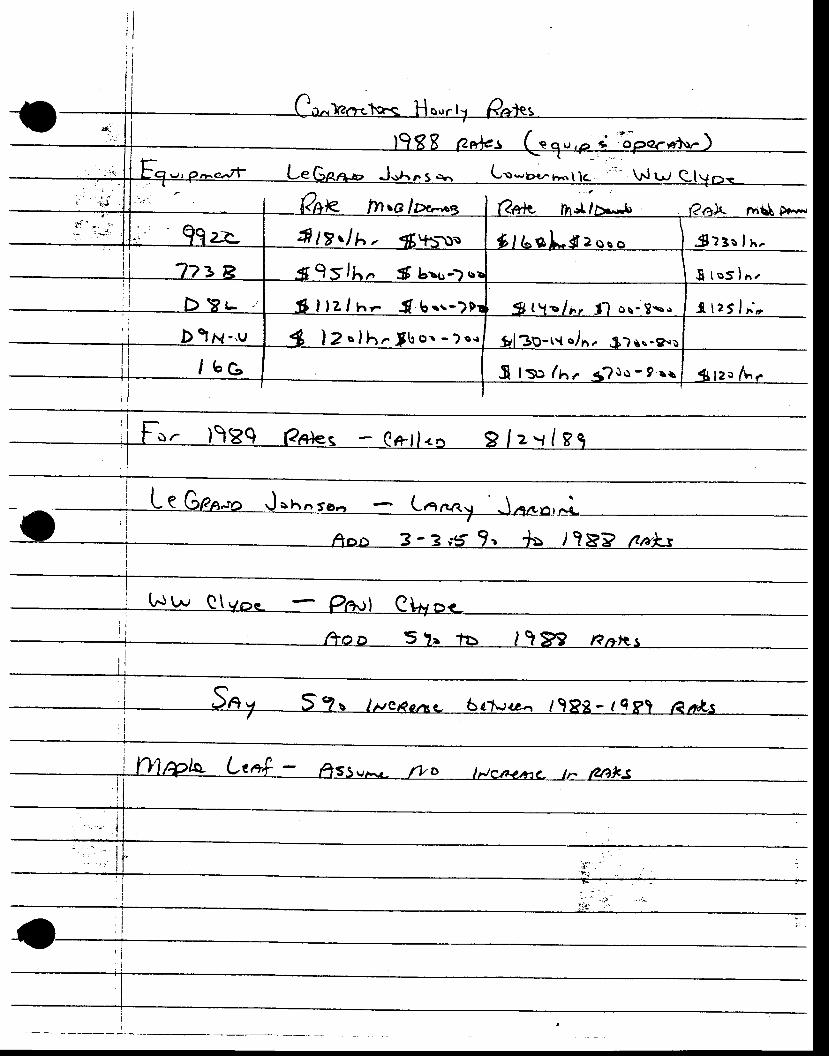
Lo-g*,^*.1 - \r.l r.t
. :X:3s lx .
I t q s ) h ,
- l l :5 f ; ,
zo /L r
fr tz.l
lz I n- . f b. . , - o s - 8 s "
2o lh . fbo . - )o . r t { c /6 '
S ts> / t . { ro -9 r r
I
- -REDACTED- -
ORIGINAL LOCArED IN DOGU CONFIDENIIIAL FILE
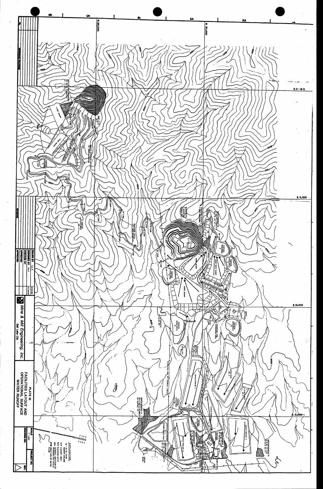
ffi:-1- - - . - . ) \ (
4,1 ((
[KSN
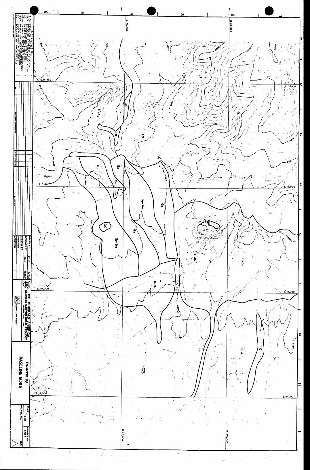
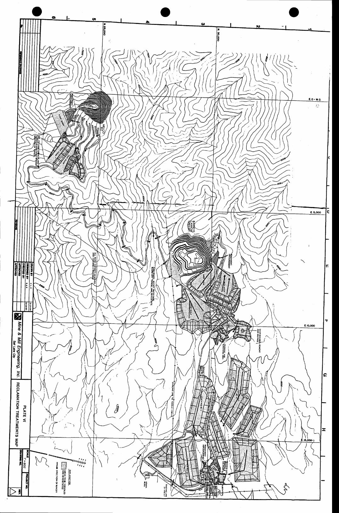
$l,\d '; [ \
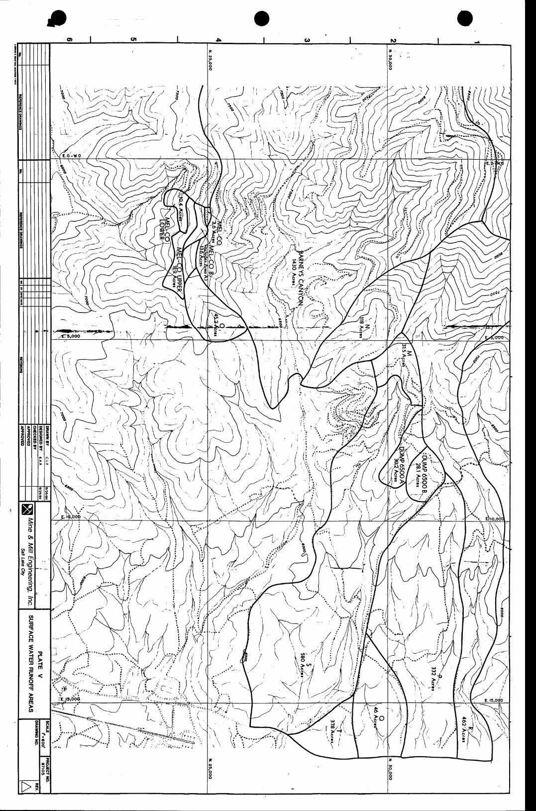
I
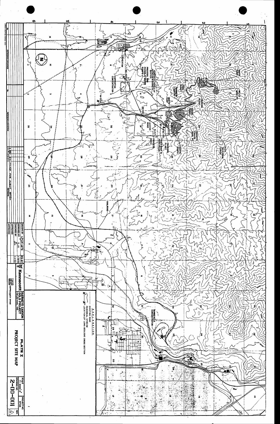
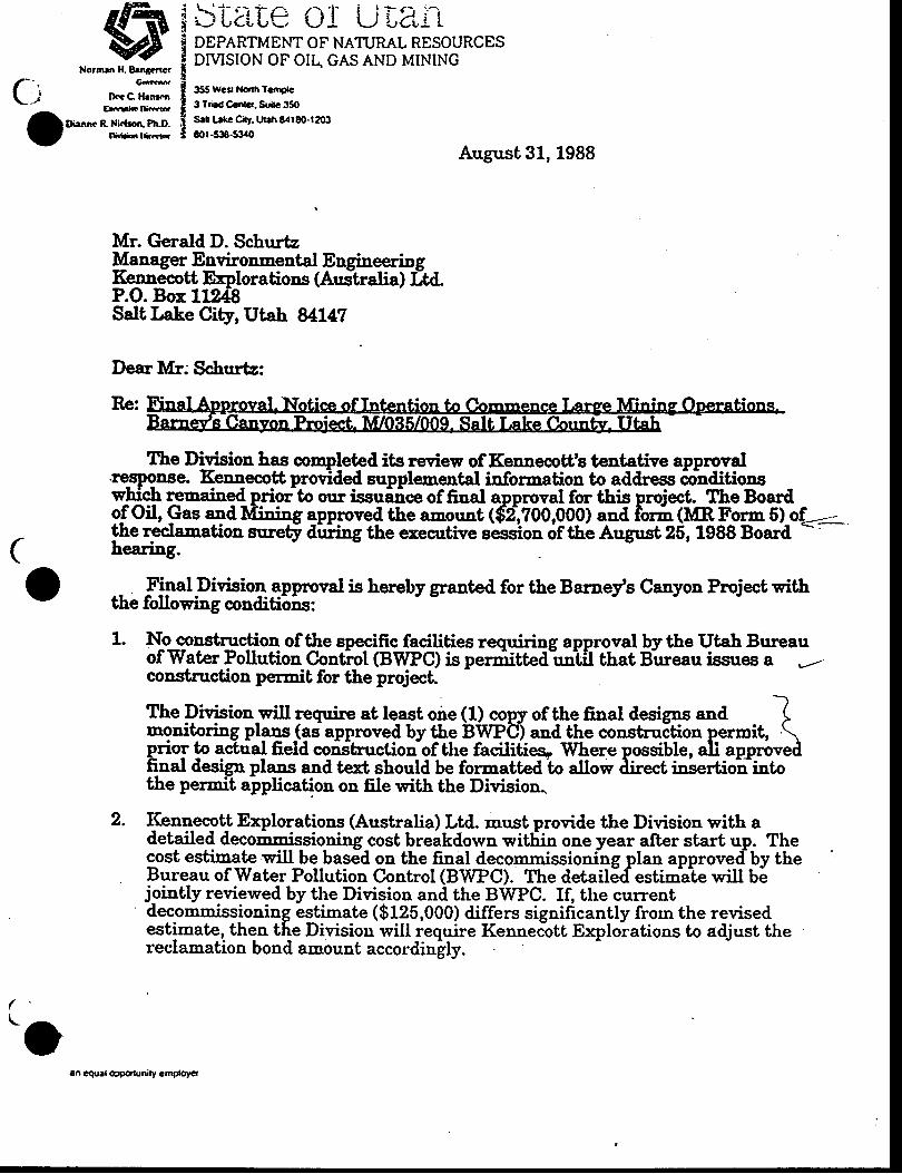
gTStAle OI U|3"itDEPARTMENT OF NATI.JRAL RESOURCESDMSION OF OII+ GAS AND MINING
355Wcsl Ndhfctngle
3 Trbd Ccnrcr. &itc 35OSet trrc Cty. uah 8rlr80-t2cBEOr -538-53.0
August 31, 1988
Norrnrn H. Een4encrl- Gmma .
L j lltcC Hen:mEKirtIGd
IDiennc R Ni.{tocP!LD.- Oirinrfimr-
Mr. Gerald D. SchurtzManager Environmental EngineeringI(enDecltt Explorations (Australia) I;td-P.O. Bor 11?;48Salt Lake City, Utah 84L47
Dear l[r; Schurtz:
Re:
The Division has completed,its review of Keunecott's teutative approvd-tresponse. Kennecott protfded suprlemental inforuation to address 6oidifionswhich reueined priorto our issuaice of final apprpval for this proiect. The Boarilo-f Oil, Gas and Mining approved the amount ($'2',?00,000) and foIn (MR Form 6l of-.--the reclamation eurety diriiDg the exesutive session 6f tUe Angust 25, 1988 Board,
- -
hearing.
- FiptlDivision approval is lrereby granted for the Barne/s Canyon Project withthe following conditions:
1. No constnrction of the specific facilities requirine approval by the Utah Bureauof
'Water Pollution Contiot (BWPC) is perniitted-unlil that B-ureau issues a L-,-
coDstruction pemit for the projecL
I(ennecott Explorations (Australia) Ltcl. must provid.e the Division with adetailed decornrnissioning cost breakd.own witf,in one year after start up. Thecost estimate will be basdd on the final decommissioning plan approoed'by theBureau of Water Pollution Control (BWPC). The detailE<f estimlle wilt b6jgintly reviewed by the Division and the BWPC. If, the currentdec-ommissioning estimate ($125,000) differs significantly frorn the revisedestimate, then the Divisiou will require Kennedott Explorations to adjust thereclamation bond amouut accordingly.
'oan Gqual ocportunity cmployer
Page 2Mr. Gerald D. SchurtzMt035t009August 29, 1988( .
o3. The Board has requested that Kennecott complete a new reclamation contract
form- The older form (MR Form E), s submi€ted, will provide adeqrratecoverage until the new forms become available. ihe re-vised formsihould befrnalized soon- A new surety bond will not have to be obtained for this project.
The Division appreciates Kennecott's patience and cooperation in completingt*.pSt-ltting activity. Plgase feel free ti coot"ct G at aiy tine shotrlit-iou h"?"additional permitting questions or coDcens.
Sincereln
-L* /Ar+4Iowell P. BraxtouiAdninistratorMineral Resource Developmentand Reclanation Prognin
'e, Barney'g Cauyoa Mine, JBR0o-nsriltaits ,
Steve Ha:ris, Magna Area Etected CouncilJerry Mansfield, State LandsP_laingJvf ilnel_OoppergellTrnprovementDistrictsraule lYluler, \rOpperEOD Ulfprovement l.ristnct$"pt Min-er, Salt Lake City/Gtuty Health Dept.Rober0 Morgan, Water niehtsDon Osler, BTII'PCWilliam lhurman, Mcl(ay, Burton and Tlurrman\Malme Iledbers
_ - _Ilolland ShephErd3/16-16
Related Documents