we give you a clearer vision LYYN Hawk Board LYYN Hawk Integration Kit Manual 2011-03-09

Welcome message from author
This document is posted to help you gain knowledge. Please leave a comment to let me know what you think about it! Share it to your friends and learn new things together.
Transcript
we give you a clearer vision
LYYN Hawk Board LYYN Hawk Integration Kit
Manual 2011-03-09
Hawk product documentation 2011-‐03-‐09 Page 2 of 36
Contents 1. The Hawk board at a glance ................................................................................................................ 5
1.1. Description ...................................................................................................................................... 5 1.2. Hawk features ................................................................................................................................ 6 1.3. Documentation and intellectual property ................................................................................ 7 1.4. Support information ...................................................................................................................... 7
2. Revision histories .................................................................................................................................... 8 2.1. Documentation revisions ............................................................................................................. 8 2.2. Hardware & Software revisions .................................................................................................. 8
3. Controlling the Hawk board ................................................................................................................ 9 3.1. Overview ......................................................................................................................................... 9 3.2. Important notes ........................................................................................................................... 10 3.3. Keypad functionality ................................................................................................................... 10 3.4. Keypad introduced mid 2010 ................................................................................................... 11 3.5. Original keypad ............................................................................................................................ 12 3.6. Definition of the position and size of the lyynification window ....................................... 13 3.7. Inverted lyynification window .................................................................................................. 14
4. Serial control commands ................................................................................................................... 15 4.1. Command summary ................................................................................................................... 15 4.2. Serial examples ............................................................................................................................ 15 4.3. Saved settings ............................................................................................................................... 15 4.4. Control panel command/setting vs. serial command/settings .......................................... 15 4.5. Default values and ranges of parameter settings ................................................................. 15 4.6. Troubleshooting .......................................................................................................................... 16
5. Kit illustrations ..................................................................................................................................... 17 5.1. Main board .................................................................................................................................... 17 5.2. Main board ribbon cable connection ...................................................................................... 18 5.3. Connector board ........................................................................................................................ 19 5.4. Control panel ............................................................................................................................... 20 5.5. Assembly ....................................................................................................................................... 21
6. Miscellaneous ........................................................................................................................................ 22 6.1. RS485 ............................................................................................................................................. 22 6.2. Video signal cables ...................................................................................................................... 23 6.3. Video synchronization ................................................................................................................ 24
7. Specifications ........................................................................................................................................ 26 8. Notices and warranty ......................................................................................................................... 28 9. Regulatory notices ............................................................................................................................... 29 10. Control reference ............................................................................................................................... 30
10.1. BRIG ............................................................................................................................................... 30 10.2. BYPA .............................................................................................................................................. 30 10.3. CHUE ............................................................................................................................................. 30
Hawk product documentation 2011-‐03-‐09 Page 3 of 36
10.4. CONT ........................................................................................................................................... 31 10.5. INVE ............................................................................................................................................... 31 10.6. LYYN ............................................................................................................................................. 31 10.7. OUTP ............................................................................................................................................. 32 10.8. POSN ............................................................................................................................................. 32 10.9. REST ............................................................................................................................................... 32 10.10. RVID ............................................................................................................................................ 33 10.11. SATU ........................................................................................................................................... 33 10.12. SERN ........................................................................................................................................... 33 10.13. SHRP ............................................................................................................................................ 34 10.14. SIZE .............................................................................................................................................. 34 10.15. SYDH ........................................................................................................................................... 34 10.16. SYDL ............................................................................................................................................ 35 10.17. SYNC ........................................................................................................................................... 35 10.18. TEST ............................................................................................................................................ 36 10.19. TOPL ........................................................................................................................................... 36
Hawk product documentation 2011-‐03-‐09 Page 4 of 36
Illustrations and tables Figures Figure 1. The Hawk board ............................................................................................................................ 5 Figure 2. Additional material in Hawk Integration Kit ........................................................................... 6 Figure 3. Controlling the Hawk board ...................................................................................................... 9 Figure 4. Keypad (mid 2010) functionality ............................................................................................. 11 Figure 5. Keypad functionality .................................................................................................................. 12 Figure 6. Position setting ........................................................................................................................... 13 Figure 7. Position & size of a selected image area ............................................................................... 14 Figure 8. Position & size of an inverted lyynification window ........................................................... 14 Figure 9. Hawk board illustration (not to scale) .................................................................................. 17 Figure 10. Hawk board layout (not to scale) ........................................................................................ 18 Figure 11. Detail of power supply connector ....................................................................................... 18 Figure 12. Location of PIN no 1 on keypad connector ...................................................................... 18 Figure 13. Hawk board with attached ribbon cable ............................................................................ 18 Figure 14. Control panel, FPC cable and ribbon cable “bottom” .................................................... 20 Figure 15. Control panel, FPC cable and ribbon cable “top” ............................................................ 20 Figure 16. FPC cable on control panel ................................................................................................... 20 Figure 17. Assembled kit with length indication ................................................................................... 21 Figure 18. “Folded” assembled kit ........................................................................................................... 21
Tables Table 1. Operating systems and communications & control alternatives ......................................... 9 Table 2. Keypad (mid 2010) functionality .............................................................................................. 11 Table 3. Keypad functionality .................................................................................................................... 12 Table 4. SIZE and POSN values ............................................................................................................... 13 Table 5. Serial examples ............................................................................................................................. 15 Table 6. Default values and ranges .......................................................................................................... 15 Table 7. SYDH & SYDL examples ........................................................................................................... 24 Table 8. Specifications ................................................................................................................................ 26
Hawk product documentation 2011-‐03-‐09 Page 5 of 36
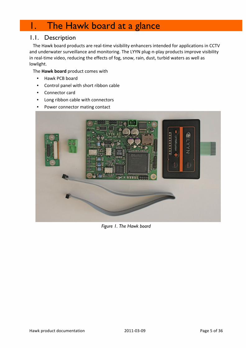
1. The Hawk board at a glance 1.1. Description The Hawk board products are real-‐time visibility enhancers intended for applications in CCTV
and underwater surveillance and monitoring. The LYYN plug-‐n-‐play products improve visibility in real-‐time video, reducing the effects of fog, snow, rain, dust, turbid waters as well as lowlight. The Hawk board product comes with
• Hawk PCB board • Control panel with short ribbon cable • Connector card • Long ribbon cable with connectors • Power connector mating contact
Figure 1. The Hawk board
Hawk product documentation 2011-‐03-‐09 Page 6 of 36
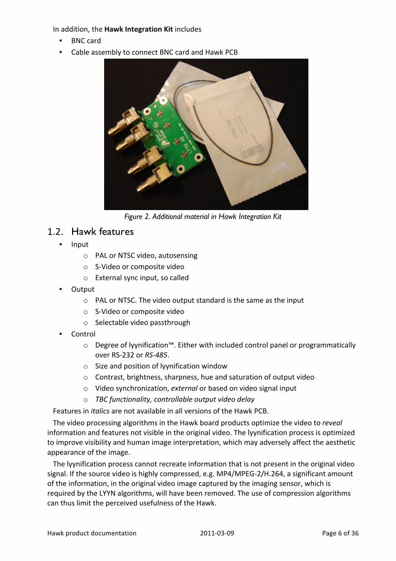
In addition, the Hawk Integration Kit includes • BNC card • Cable assembly to connect BNC card and Hawk PCB
Figure 2. Additional material in Hawk Integration Kit
1.2. Hawk features • Input
o PAL or NTSC video, autosensing o S-‐Video or composite video o External sync input, so called
• Output o PAL or NTSC. The video output standard is the same as the input o S-‐Video or composite video o Selectable video passthrough
• Control o Degree of lyynification™. Either with included control panel or programmatically
over RS-‐232 or RS-‐485. o Size and position of lyynification window o Contrast, brightness, sharpness, hue and saturation of output video o Video synchronization, external or based on video signal input o TBC functionality, controllable output video delay
Features in italics are not available in all versions of the Hawk PCB. The video processing algorithms in the Hawk board products optimize the video to reveal
information and features not visible in the original video. The lyynification process is optimized to improve visibility and human image interpretation, which may adversely affect the aesthetic appearance of the image. The lyynification process cannot recreate information that is not present in the original video
signal. If the source video is highly compressed, e.g. MP4/MPEG-‐2/H.264, a significant amount of the information, in the original video image captured by the imaging sensor, which is required by the LYYN algorithms, will have been removed. The use of compression algorithms can thus limit the perceived usefulness of the Hawk.
Hawk product documentation 2011-‐03-‐09 Page 7 of 36
The degree of enhancement achievable through lyynification depends on the input image quality. When the input video has low levels of visual disturbance the Hawk will make the image slightly clearer, similar to replacing poor optics with better. At larger degrees of lyynification the Hawk may amplify previously invisible image noise or somewhat exaggerate some colors in the input video to make objects and details more visible.
1.3. Documentation and intellectual property This document is the complete Hawk product documentation. The description and
specifications of this product are subject to future change without notice. This document is intended for users capable of performing basic PC, TCP/IP network and
video equipment operations. Analysis, reverse engineering, decompiling and disassembling of the software, hardware or
manuals that accompany this product, and all other related products including miscellaneous supplemental items, is prohibited
1.4. Support information Address LYYN AB
IDEON Science Park, Scheelevägen 17 S-‐223 70 Lund Sweden
Contact www.lyyn.com/support, [email protected] LYYN and its logo are registered trademarks of LYYN AB. Other product names and related
items are trademarks or registered trademarks of their respective companies. © 2010, LYYN AB
Hawk product documentation 2011-‐03-‐09 Page 8 of 36
2. Revision histories 2.1. Documentation revisions
Manual revision Comment/Changes
R1.0 2008-‐03-‐28 First complete draft
R1.1 2008-‐04-‐16 First release to customers
R1.2 2008-‐05-‐08 Minor corrections
R1.3 2008-‐05-‐19 Minor corrections
R1.4 2008-‐05-‐20 Minor corrections and correct RS485 info, i.e. RS485 not implemented
R1.5 2008-‐09-‐23 Current version. Released for HW 1C with RS485 support and new panel button functionality
R1.6 2008-‐10-‐06 Updated revision history due to new SW revisions
R1.7 2008-‐10-‐22 Added missing information about flow control for RS232/RS485 connections
R2.0 2008-‐10-‐30 Revised HW and SW revision information, merged manual versions for the HW branches
R3.0 2009-‐02-‐19 Revised document structure. Added information related to new product(s)
R3.1 2009-‐03-‐09 Changed formatting and made small corrections
R3.2 2009-‐06-‐18 Added missing commands in command reference
R4.0 2010-‐06-‐08 Added documentation about inverse lyynfication selection window
R4.1 2010-‐08-‐30 Revised outline of document and command table
R4.2 2010-‐11-‐23 Added info on REST command
2011-‐03-‐09 Updates after latest software revisions
2.2. Hardware & Software revisions There are 2 hardware versions of the Hawk board
• R1B hardware. This is the original Hawk hardware without RS-‐485 support. • R1C and R1D hardware. Improved Hawk hardware version with RS-‐485 support.
Comment FPGA revision PIC revision FPGA version PIC version Current SW for R1B hardware 2009-‐02-‐11 2009-‐02-‐11 Current SW for R1C hardware 2009-‐02-‐05 2009-‐02-‐11 Current SW for R1D hardware 2011-‐02-‐17 or 2011-‐03-‐06 2010-‐12-‐13
Hawk product documentation 2011-‐03-‐09 Page 9 of 36
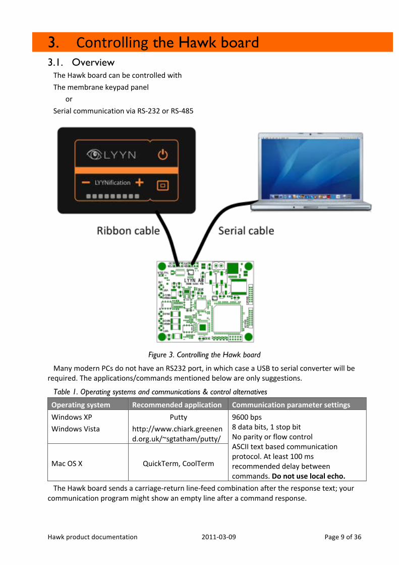
3. Controlling the Hawk board 3.1. Overview The Hawk board can be controlled with The membrane keypad panel
or Serial communication via RS-‐232 or RS-‐485
Figure 3. Controlling the Hawk board
Many modern PCs do not have an RS232 port, in which case a USB to serial converter will be required. The applications/commands mentioned below are only suggestions.
Table 1. Operating systems and communications & control alternatives
Operating system Recommended application Communication parameter settings Windows XP Windows Vista
Putty http://www.chiark.greenend.org.uk/~sgtatham/putty/
9600 bps 8 data bits, 1 stop bit No parity or flow control ASCII text based communication protocol. At least 100 ms recommended delay between commands. Do not use local echo.
Mac OS X QuickTerm, CoolTerm
The Hawk board sends a carriage-‐return line-‐feed combination after the response text; your communication program might show an empty line after a command response.
Hawk product documentation 2011-‐03-‐09 Page 10 of 36
There is no prioritization between keypad and serial port, i.e. the latest command overrides previous ones. All settings are retained when the power is turned off. Note: factory default settings are used the first time the unit is powered up.
3.2. Important notes The DC power input is not polarity protected. Please take care to check the polarity of your power source before connecting it to the Hawk
board. The Hawk can switch between composite and S-‐video, it cannot convert PAL to NTSC or vice-‐
versa. The first time a Hawk board is powered, and after a REST command, it selects composite NTSC output.
3.3. Keypad functionality A thin “membrane” keypad panel is supplied with the Hawk board. It can be mounted on a
flat surface with the adhesive backing. If the application requires a watertight seal we recommend extra sealant. The panel is connected to the HAWK BOARD with a flat cable (included) and there are 4 buttons on the panel.
Hawk product documentation 2011-‐03-‐09 Page 11 of 36
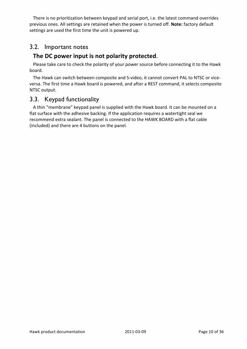
3.4. Keypad introduced mid 2010 A new keypad was introduced in mid 2010. The physizal size, the symbols and the placement
of LED indicators have been changed.
Figure 4. Keypad (mid 2010) functionality
Table 2. Keypad (mid 2010) functionality
Button Function
Lyynification on/off. Lyynification OFF = analog bypass
Successive clicks cycle through lyynification windo sizes
Click to decrease degree of lyynification
Click to increase degree of lyynification
Press and hold + click Cycle through lyynification window positions
Press and hold + click Switch between normal and inverse selection rectangle. Available from SW rev 20100607
!""#$%&'()#*)#+),
-.&/.'0.**1.2/..*)3*4""#$%&'()# 5#&/.'0.**1.2/..*)3*4""#$%&'()#
67&&.00$8.*&4$&90*&"&4.0:;/)72;*4""#$%&'()#*<$#1)<*0$=.0
>/.00*'#1*;)41***********?*&4$&9**********@*A"&4.*:;/)72;*4""#$%&'()#*<$#1)<*B)0$()#0
>/.00*'#1*;)41*************?*&4$&9**********@*C)224.*#)/D'4*'#1*$#8./0.*4""#$%&'()#*<$#1)<
!""#$%&'()#*0:/.#2:;*$#1$&':)/
Hawk product documentation 2011-‐03-‐09 Page 12 of 36
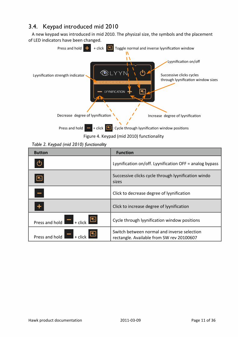
3.5. Original keypad
Figure 5. Keypad functionality
Table 3. Keypad functionality
Button Function
Lyynification on/off. Lyynification OFF = analog bypass
Successive clicks cycle through lyynification window sizes
Click to decrease degree of lyynification
Click to increase degree of lyynification
Press and hold + click Cycle through lyynification window positions
Press and hold + click Switch between normal and inverse selection rectangle. Available from SW rev 20100607
!""#$%&'()#*)#+),
-.&/.'0.**1.2/..*)3*4""#$%&'()# 5#&/.'0.**1.2/..*)3*4""#$%&'()#
67&&.00$8.*&4$&90*&"&4.0:;/)72;*4""#$%&'()#*<$#1)<*0$=.0
>/.00*'#1*;)41***********?*&4$&9**********@*A"&4.*:;/)72;*4""#$%&'()#*<$#1)<*B)0$()#0
>/.00*'#1*;)41***********?*&4$&9**********@*C)224.*#)/D'4*'#1*$#8./0.*4""#$%&'()#*<$#1)<
!""#$%&'()#*0:/.#2:;*$#1$&':)/
Hawk product documentation 2011-‐03-‐09 Page 13 of 36
3.6. Definition of the position and size of the lyynification window
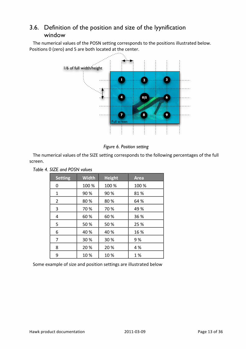
The numerical values of the POSN setting corresponds to the positions illustrated below. Positions 0 (zero) and 5 are both located at the center.
Figure 6. Position setting
The numerical values of the SIZE setting corresponds to the following percentages of the full screen.
Table 4. SIZE and POSN values
Setting Width Height Area 0 100 % 100 % 100 % 1 90 % 90 % 81 % 2 80 % 80 % 64 % 3 70 % 70 % 49 % 4 60 % 60 % 36 % 5 50 % 50 % 25 % 6 40 % 40 % 16 % 7 30 % 30 % 9 % 8 20 % 20 % 4 % 9 10 % 10 % 1 %
Some example of size and position settings are illustrated below
Full screen
1 2 3
4 0|5 6
7 8 9
1/6 of full width/height
Hawk product documentation 2011-‐03-‐09 Page 14 of 36
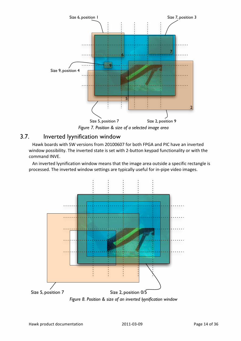
Figure 7. Position & size of a selected image area
3.7. Inverted lyynification window Hawk boards with SW versions from 20100607 for both FPGA and PIC have an inverted
window possibility. The inverted state is set with 2-‐button keypad functionality or with the command INVE. An inverted lyynification window means that the image area outside a specific rectangle is
processed. The inverted window settings are typically useful for in-‐pipe video images.
Figure 8. Position & size of an inverted lyynification window
5
6
2
9
7
Size 2, position 9Size 5, position 7
Size 9, position 4
Size 6, position 1 Size 7, position 3
Size 2, position 0/5Size 5, position 7
Hawk product documentation 2011-‐03-‐09 Page 15 of 36
4. Serial control commands 4.1. Command summary Each command consists of a 4-‐character command name followed by a question mark (?), 1-‐3
digits or nothing. A question mark indicates a query concerning the current value of the specified command; digits indicate the setting of a command. A command is terminated/sent by pressing the Return/Enter key denoted <cr> below.
4.1.1. Serial port responses • There is no prompt character. • The response to a parameter change command is a LFCR followed by parameter value
followed by a LFCR. • The response to a query command is a LFCR followed by parameter value followed by a
LFCR. • The normal power up serial port output is Lyyn...Mem OK • The serial port output after a REST command or at initial power up is Lyyn...Mem OK
4.2. Serial examples Table 5. Serial examples
Command Meaning and/or expected response LYYN3<cr> Set the degree of lyynification to 3 for the selected channel BRIG?<cr> Retrieve the current brightness setting for the selected channel SERN? Retrieves current serial numbers
4.3. Saved settings All settings are automatically saved when the power is turned off, i.e. the last values used are
retained. This applies to settings made via the serial port and using the control panel. Note: factory default settings are used the first time the unit is powered up..
4.4. Control panel command/setting vs. serial command/settings There is no difference in priority between a setting made with the control panel and one
made via a serial interface. The lyynification display LEDs, for example, will thus reflect the most recent value of the degree of lyynification regardless of whether it was set via the control panel or the serial port.
4.5. Default values and ranges of parameter settings Table 6. Default values and ranges
Setting/command Default Comment Range Color standard NTSC Controlled by jumper setting internally. Only
applicable at first power-‐on and after reset. N.A
BRIG 128 128 = no modification 0 – 255 BYPA 0 lyynification on 0 – 1 CHUE 128 128 = no modification of color hue 0 – 255 CONT 128 128 = no modification of contrast 0 – 255 LYYN 0 Zero lyynification 0 – 9 OUTP 0 Auto switching 0 -‐ 2 POSN 0 Center position of lyynification window 0 -‐ 9 SATU 128 Color saturation 0 – 255
Hawk product documentation 2011-‐03-‐09 Page 16 of 36
SHRP 0 0 = no modification of sharpness 0 – 3 SIZE 0 Size of lyynification window = full screen 0 – 9 SYNC 0 Synchronized by incoming video signal,
maximum delay approx. 140 µs 0 -‐ 1
TEST 0 Test image shown if there is no input signal 0 -‐ 2 TOPL 4 This has been found to be a suitable value 0 – 30
4.6. Troubleshooting Test image visible: If a test image is visible on the output you have either lost your input signal
or the input signal quality has been severely degraded. Dark/black image visible: This might depend on the use of an external sync signal. Use of a
TBC might correct the problem. Black & white image visible: Check that you are using the right combination of composite or S-‐
video connections. Symptom Remedy The test image is shown If a test image is shown at the output there is no input signal, or the
quality of the input signal is too low to be lyynified. The outout image is dark or black
This may be due to the use of an external sync signal. Using a TBC may correct the problem.
The output image is in black & white
Check that you are using the right combination of composite or S-‐video connections.
Please point your browser at http://www.lyyn.com/support for more troubleshooting tips. The Hawk has professional grade components with high tolerance to different video sources
and signal. However, a number of factors may affect its performance. • The signal loss in a long cable, or a bad connection, may reduce the signal so the color
burst is lost or too weak to be interpreted correctly. • Low-‐quality video signals or low-‐quality sync signaling will result in degradation of the
Hawk output or loss of the output video. • In a large system setup, i.e. multiple sources and one viewing station, it is advantageous
if a common time base is used.
Hawk product documentation 2011-‐03-‐09 Page 17 of 36
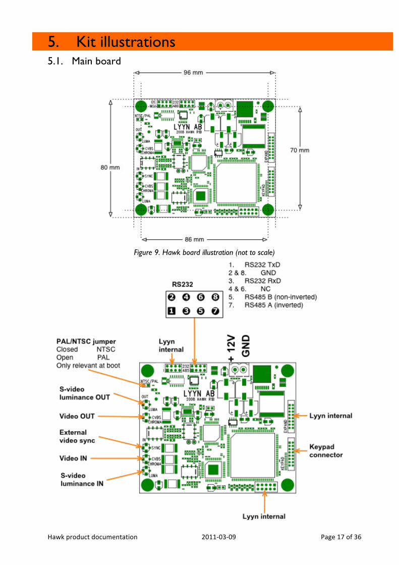
5. Kit illustrations 5.1. Main board
Figure 9. Hawk board illustration (not to scale)
Hawk product documentation 2011-‐03-‐09 Page 18 of 36
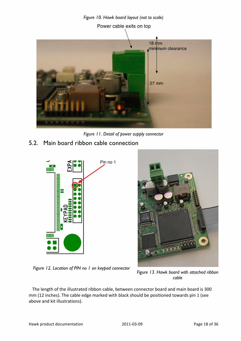
Figure 10. Hawk board layout (not to scale)
Figure 11. Detail of power supply connector
5.2. Main board ribbon cable connection
Figure 12. Location of PIN no 1 on keypad connector
Figure 13. Hawk board with attached ribbon cable
The length of the illustrated ribbon cable, between connector board and main board is 300 mm (12 inches). The cable edge marked with black should be positioned towards pin 1 (see above and kit illustrations).
Hawk product documentation 2011-‐03-‐09 Page 19 of 36
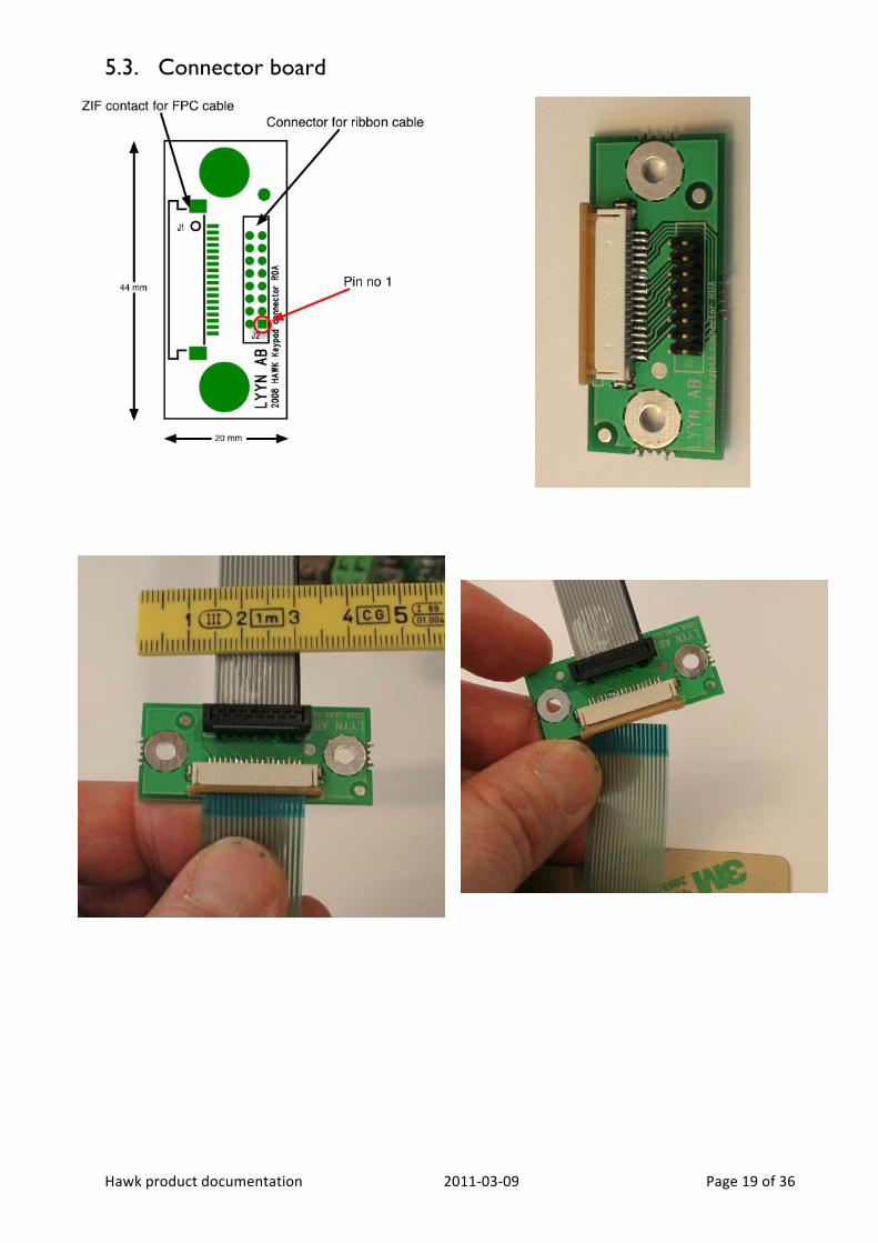
5.3. Connector board
Hawk product documentation 2011-‐03-‐09 Page 20 of 36
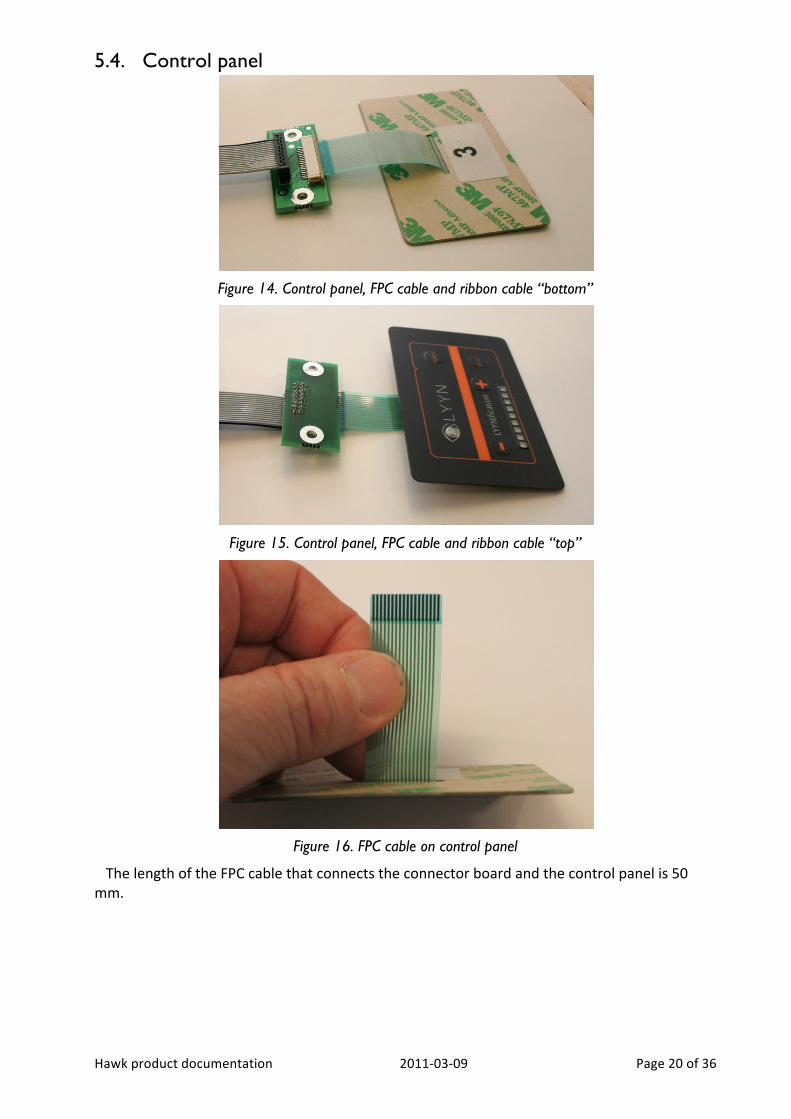
5.4. Control panel
Figure 14. Control panel, FPC cable and ribbon cable “bottom”
Figure 15. Control panel, FPC cable and ribbon cable “top”
Figure 16. FPC cable on control panel
The length of the FPC cable that connects the connector board and the control panel is 50 mm.
Hawk product documentation 2011-‐03-‐09 Page 21 of 36
5.5. Assembly
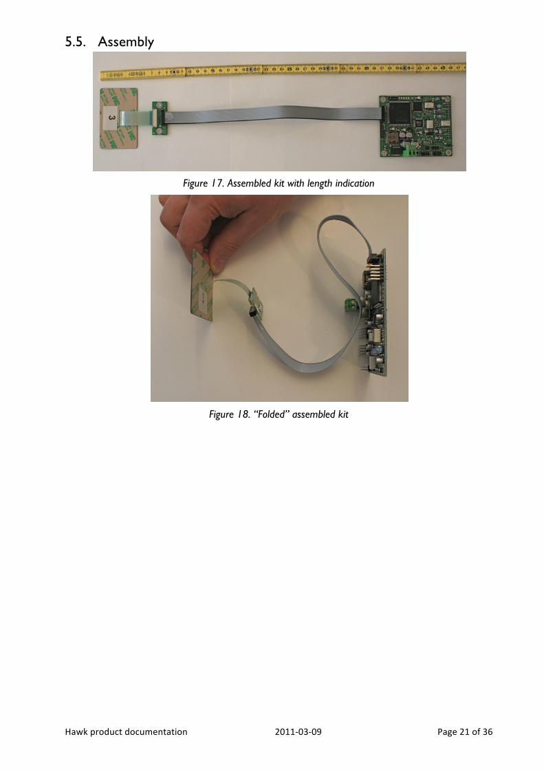
Figure 17. Assembled kit with length indication
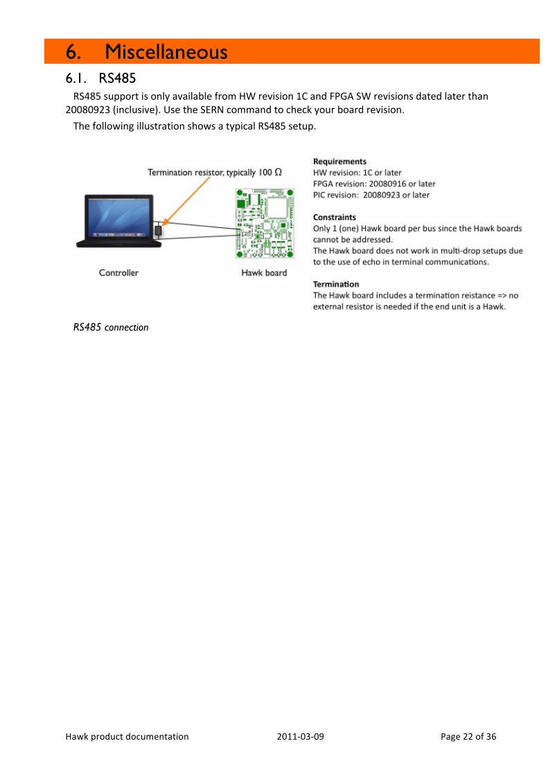
Figure 18. “Folded” assembled kit
Hawk product documentation 2011-‐03-‐09 Page 22 of 36
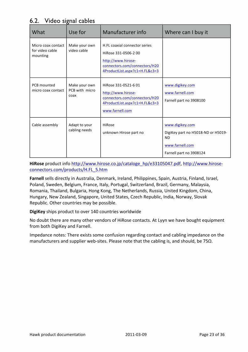
6. Miscellaneous 6.1. RS485 RS485 support is only available from HW revision 1C and FPGA SW revisions dated later than
20080923 (inclusive). Use the SERN command to check your board revision. The following illustration shows a typical RS485 setup.
RS485 connection
Hawk product documentation 2011-‐03-‐09 Page 23 of 36
6.2. Video signal cables
What Use for Manufacturer info Where can I buy it
Micro coax contact for video cable mounting
Make your own video cable
H.FL coaxial connector series
HiRose 331-‐0506-‐2 00
http://www.hirose-‐connectors.com/connectors/H204ProductList.aspx?c1=H.FL&c3=3
PCB mounted micro coax contact
Make your own PCB with micro coax
HiRose 331-‐0521-‐6 01
http://www.hirose-‐connectors.com/connectors/H204ProductList.aspx?c1=H.FL&c3=3
www.farnell.com
www.digikey.com
www.farnell.com
Farnell part no 3908100
Cable assembly Adapt to your cabling needs
HiRose
unknown Hirose part no
www.digikey.com
DigiKey part no H5018-‐ND or H5019-‐ND
www.farnell.com
Farnell part no 3908124
HiRose product info http://www.hirose.co.jp/cataloge_hp/e33105047.pdf, http://www.hirose-‐connectors.com/products/H.FL_5.htm
Farnell sells directly in Australia, Denmark, Ireland, Philippines, Spain, Austria, Finland, Israel, Poland, Sweden, Belgium, France, Italy, Portugal, Switzerland, Brazil, Germany, Malaysia, Romania, Thailand, Bulgaria, Hong Kong, The Netherlands, Russia, United Kingdom, China, Hungary, New Zealand, Singapore, United States, Czech Republic, India, Norway, Slovak Republic. Other countries may be possible.
DigiKey ships product to over 140 countries worldwide
No doubt there are many other vendors of HiRose contacts. At Lyyn we have bought equipment from both DigiKey and Farnell.
Impedance notes: There exists some confusion regarding contact and cabling impedance on the manufacturers and supplier web-‐sites. Please note that the cabling is, and should, be 75Ω.
Hawk product documentation 2011-‐03-‐09 Page 24 of 36
6.3. Video synchronization The Hawk board has 3 video synchronization modes 1. Internal synchronization whereby the output video signal follows (= is synchronized to)
the input video signal with a 140 µs delay. 2. External synchronization whereby the output video signal follows (= is synchronized to)
an synchronization signal at the external sync connector. 3. Controlled delay whereby the output video signal follows (= is synchronized to) the input
video signal with a 140 µs + a controllable number of microseconds delay. The lyynification process is a computationally intensive process and unavoidably introduces a
delay of 140 µs (microseconds). Controlled delay is not available on some combinations of hardware and software. See Figure
1.
6.3.1. SYDH & SYDL commands The range of synchronization time delay is 0 – 20 000 microseconds thus requiring a two-‐byte
representation. The value is given by the following expression
SYDHx * 256 + SYDLy µs The table below exemplifies two cases
Table 7. SYDH & SYDL examples Time delay Commands Explanation
1537 SYDL1 Integer remainder of 1537/16 (1537 modulo 256) = 1 SYDH6 Integer result of 1537/256 = 6
12049 SYDL17 Integer remainder of 12049/16 (12049modulo 256) = 17 SYDH47 Integer result of 12049/256 = 247
6.3.2. Internal sync Sending the SYNC0 command to the selected channel sets internal synchronization. The SYDH
& SYDL commands have no effect if the channel is set to internal synchronization. The total delay for internal sync mode is
140 µs
6.3.3. External sync The Hawk board does not, by itself, support line-‐sync. An external sync signal must be
supplied. Sending the SYNC1 command to the board sets external synchronization. The SYND command
can be used in combination with external sync thus adding a controllable additional delay to the output. The total delay for external sync mode is
140 + 1 full frame (40 ms for PAL and 33 ms for NTSC) + SYDHx * 256 + SYDLy µs 6.3.4. Controlled delay (TBC functionality) Sending the SYNC2 command to the board sets controlled delay synchronization. The SYDH
and SYDL commands can be used in combination with “controlled delay sync” thus adding a controllable delay to the output. The total delay for “controlled delay sync” mode is
140 + SYDHx * 256 + SYDLy µs
Hawk product documentation 2011-‐03-‐09 Page 25 of 36
6.3.5. External sync waveform requirements The Hawk board accepts a so-‐called VD sync signal, sometimes also called a vertical blanking,
vertical sync etc. A VD signal could be a pulse with the repeat rate of 20/16.7ms ( 50/60 Hz) a pulse width of ≈ 10 µs at 1 Vpp. A vertical blanking sync pulse from a composite video signal is perfect.
Hawk product documentation 2011-‐03-‐09 Page 26 of 36
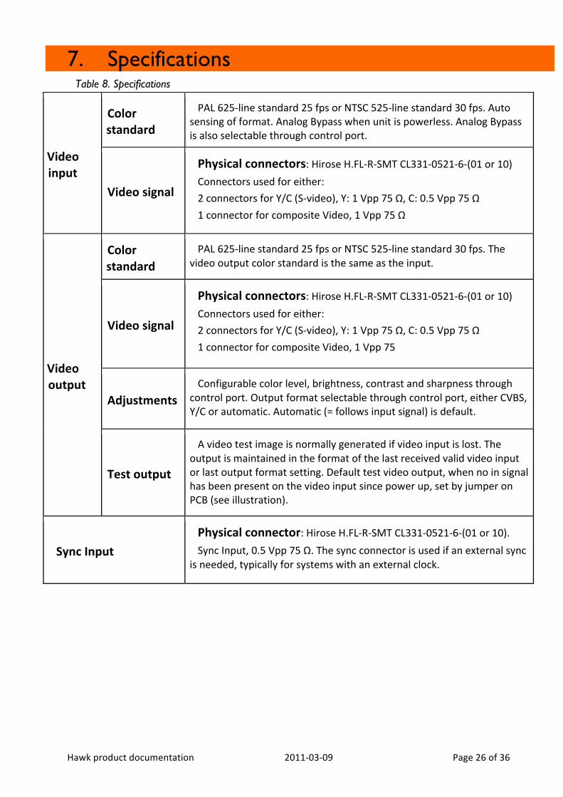
7. Specifications Table 8. Specifications
Video input
Color standard
PAL 625-‐line standard 25 fps or NTSC 525-‐line standard 30 fps. Auto sensing of format. Analog Bypass when unit is powerless. Analog Bypass is also selectable through control port.
Video signal
Physical connectors: Hirose H.FL-‐R-‐SMT CL331-‐0521-‐6-‐(01 or 10) Connectors used for either: 2 connectors for Y/C (S-‐video), Y: 1 Vpp 75 Ω, C: 0.5 Vpp 75 Ω 1 connector for composite Video, 1 Vpp 75 Ω
Video output
Color standard
PAL 625-‐line standard 25 fps or NTSC 525-‐line standard 30 fps. The video output color standard is the same as the input.
Video signal
Physical connectors: Hirose H.FL-‐R-‐SMT CL331-‐0521-‐6-‐(01 or 10) Connectors used for either: 2 connectors for Y/C (S-‐video), Y: 1 Vpp 75 Ω, C: 0.5 Vpp 75 Ω 1 connector for composite Video, 1 Vpp 75
Adjustments Configurable color level, brightness, contrast and sharpness through
control port. Output format selectable through control port, either CVBS, Y/C or automatic. Automatic (= follows input signal) is default.
Test output
A video test image is normally generated if video input is lost. The output is maintained in the format of the last received valid video input or last output format setting. Default test video output, when no in signal has been present on the video input since power up, set by jumper on PCB (see illustration).
Sync Input Physical connector: Hirose H.FL-‐R-‐SMT CL331-‐0521-‐6-‐(01 or 10). Sync Input, 0.5 Vpp 75 Ω. The sync connector is used if an external sync
is needed, typically for systems with an external clock.
Hawk product documentation 2011-‐03-‐09 Page 27 of 36
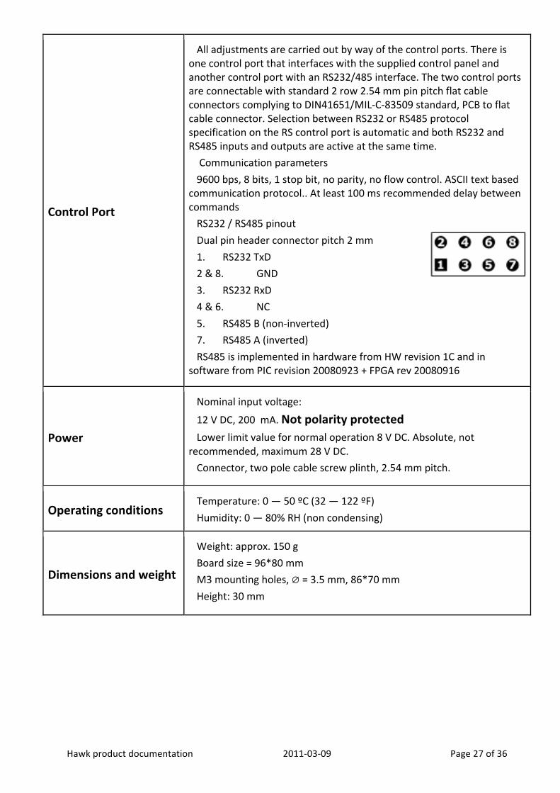
Control Port
All adjustments are carried out by way of the control ports. There is one control port that interfaces with the supplied control panel and another control port with an RS232/485 interface. The two control ports are connectable with standard 2 row 2.54 mm pin pitch flat cable connectors complying to DIN41651/MIL-‐C-‐83509 standard, PCB to flat cable connector. Selection between RS232 or RS485 protocol specification on the RS control port is automatic and both RS232 and RS485 inputs and outputs are active at the same time. Communication parameters 9600 bps, 8 bits, 1 stop bit, no parity, no flow control. ASCII text based
communication protocol.. At least 100 ms recommended delay between commands RS232 / RS485 pinout Dual pin header connector pitch 2 mm 1. RS232 TxD 2 & 8. GND 3. RS232 RxD 4 & 6. NC 5. RS485 B (non-‐inverted) 7. RS485 A (inverted) RS485 is implemented in hardware from HW revision 1C and in
software from PIC revision 20080923 + FPGA rev 20080916
Power
Nominal input voltage:
12 V DC, 200 mA. Not polarity protected Lower limit value for normal operation 8 V DC. Absolute, not
recommended, maximum 28 V DC. Connector, two pole cable screw plinth, 2.54 mm pitch.
Operating conditions Temperature: 0 — 50 ºC (32 — 122 ºF) Humidity: 0 — 80% RH (non condensing)
Dimensions and weight
Weight: approx. 150 g Board size = 96*80 mm M3 mounting holes, ∅ = 3.5 mm, 86*70 mm Height: 30 mm
Hawk product documentation 2011-‐03-‐09 Page 28 of 36
8. Notices and warranty
Date: 10 February 2009
POST AND VISITING ADDRESS
LYYN AB, Ideon Science Park, Scheelevägen 17, S-223 70 Lund, Sweden PHONE NO: +46 46 286 57 90; E-MAIL: [email protected]; WEBSITE: www.lyyn.com
NOTICES AND TERMS OF WARRANTY – LYYN PRODUCTS
1. Validity and scope The warranty is effective and valid for twelve months commencing at the time of purchase from LYYN or an authorised LYYN agent or distributor (the “Warranty Period”). LYYN shall hereunder remedy any defect or nonconformity (hereinafter termed defect(s)) resulting from faulty manufacture, design, materials or workmanship!provided that the product has not been subjected to misuse, abuse or non-LYYN authorized alterations, modifications and/or repair. This warranty is in lieu of all other warranties of merchantability and fitness for any particular purpose. The below shall be the sole remedy of the Customer for any defects or breach of warranty. 2. Warranty Repair Service LYYN undertakes to repair all defects appearing in the purchased LYYN product and reported to LYYN during the Warranty Period to which these Terms of Warranty apply. All and any warranty claim shall include a dated bill of purchase or corresponding document evidencing the vendor and the time of he purchase by the party making the warranty claim. LYYN shall ensure that the handling time be held as short as possible and that every reasonable effort is made to have the problem resolved within a reasonable time of receiving contact from the Customer informing LYYN of a problem and delivery of the warranty object. LYYN and its affiliates will maintain a sufficient stock of all parts required to service the warranty object during the Warranty Period. Warranty repair shall be carried out at the place where the product or system is located unless LYYN deems it appropriate that the defective part or object as such is returned to LYYN for repair or replacement. Terms for shipping and freight are specified under paragraph 5 below. LYYN will respond to any reported warranty claim and will undertake to implement a repair in its best and most cost effective way available, reasonable and possible. If the warranty claim is shown to be an actual failure of the LYYN unit, which can be proved to be caused by faulty manufacture, design, materials or workmanship, then the cost of repair will be borne by LYYN. On the other hand, if the problem provoking the warranty claim is shown not to be caused by faulty manufacture, design, materials or workmanship, then the Customer is liable and the repair will be made against a purchase order for such repair and all costs associated with the matter shall be borne by the Customer. LYYN will undertake such non-warranty repair under the above conditions against a Customer purchase order as per LYYN valid pricing and conditions at the time of the repair. LYYN will also charge any and all travel, living costs and freight at cost. 3. Exceptions The warranty shall not include defects resulting from:
(a) Acts of violence or deliberate damage, (b) Incorrect maintenance or handling, (c) Repair of, or alterations to the service object carried out by other
than those authorized by LYYN, (d) Omission to report in writing damages to LYYN within 2 weeks, (e) Fire, explosion, flood, mechanical, chemical, or molten metal
damage and/or similar events, (f) Excessive wear or damage caused by Customer use.
LYYN will undertake repair of defects resulting from the above (a)-(f) only against a Customer purchase order as per LYYN valid pricing and conditions at the time of the repair. LYYN will charge any and all travel, living costs and freight at cost. 4. Safety Information Always protect your LYYN product against static electricity. An electrostatic discharge may damage components of this product. Do not directly touch any of the connectors or component surfaces. Static electricity can be generated on clothing and on people. Before handling the product, discharge static electricity from your body by touching a grounded metal surface. Do not disassemble. Do not operate at other than the specified voltage. Operation at other than the rated voltages may result in fire or malfunction. Failure to follow these user guidelines qualifies as misuse. 5. Freight Packing and shipping the service object is the responsibility of the Customer for the freight to LYYN. LYYN carries this responsibility for the return of the service object to the Customer. All shipping and associated costs are at the cost and risk to the Customer unless it can be shown that the repair was due to a problem caused by faulty manufacture, design, materials or workmanship on the part of LYYN, with the exceptions stated above.
6. Responsibility for the service performed LYYN warrants its repair work for three months, or for the duration of the initial warranty period, whichever is the longest. Any repair performed as a result of faulty service is subject to the same rules as for any other warranty repair under this warranty. Faulty service or warranty repair is to be reported immediately to LYYN.
7. Discharge of Liability LYYN assumes no responsibility or liability for personal injuries even if it can be proven that the injury was caused by negligence in connection with the performance of LYYN' service or warranty undertakings. LYYN will not, in any case, be liable for damage to Customers or any third party’s property, real or moveable estate, machinery, or instrument of any kind, which applies also to cases of practical application of any LYYN product.! LYYN is explicitly not liable in contract, tort or otherwise for incidental, consequential, special or indirect damages, including without limitation, lost business profits, arising out of the use of, or inability to use, the LYYN product. 8. Fees Fees for services provided by LYYN under this warranty and not covered by the warranty are as per quotation/invoice issued for each occasion based on the LYYN price list applicable at the time. Changes to the LYYN price lists become effective as issued by LYYN. 9. Payment Fees for repair services not covered by the warranty are to be paid in arrears as per the terms of the respective LYYN invoice. 10. Grounds of exemption from liability (force majeure) The following circumstances shall be deemed as grounds for exception from liability: labour disputes and all other circumstances beyond the control of the parties, such as fire, war, mobilization or unforeseen military call-up of corresponding scope, requisition, seizure, currency or exchange restrictions, uprising, riots, general shortage of goods, as well as faulty, or delayed deliveries from sub-contractors owing to circumstances listed immediately above. It is incumbent on the party desiring to refer to circumstances as specified in the above paragraph to so inform the other party, in writing, indicating the occurrence in question, as well as to inform the other party of the discontinuance of such circumstances. 11. Disputes and governing law Swedish law shall govern the warranty and these Terms of Warranty. Any dispute, controversy or claim arising out of, or in connection with, the agreement to which these Terms of Warranty apply, or the breach, termination or invalidity thereof, shall be finally settled by arbitration in accordance with the Arbitration Rules of the Arbitration Institute of the Stockholm Chamber of Commerce. The arbitral tribunal shall be composed of three arbitrators and the seat of the arbitration shall be Malmö, Sweden. If nothing to the contrary is specified in any written and by LYYN signed agreement, the terms and regulations of LYYN’ General Conditions shall apply. 12. Cautions The products may not be used in environments requiring a high degree of reliability and safety. LYYN products are intended to be visual aids only and shall at no time replace the responsibility of the Customer or user to ensure the security of personnel, equipment or machinery. The product is not to be used in manned vehicles, nuclear or other power generating facilities, medical devices or life support systems, or any other inherently dangerous application, when failure to perform can reasonably be expected to result in a significant injury to the user or to equipment in, or for which the LYYN product is used. The product is not intended for use with such systems. The analysis, reverse engineering, decompiling and disassembling of the software, hardware or manuals that accompany the LYYN product, and all other related products including miscellaneous supplemental items, are prohibited. The description and specifications of this product are subject to future change without notice. Every effort has been made to ensure that the description of the LYYN product and manuals are as complete as possible. If the reader is aware of any questionable points, errors or omissions, please contact LYYN immediately. LYYN and its logo are registered trademarks of LYYN AB. HAWK and
T38 are acquired and claimed trademarks of LYYN AB. Other product names and related items are trademarks or registered trademarks of
their respective companies.
Hawk product documentation 2011-‐03-‐09 Page 29 of 36
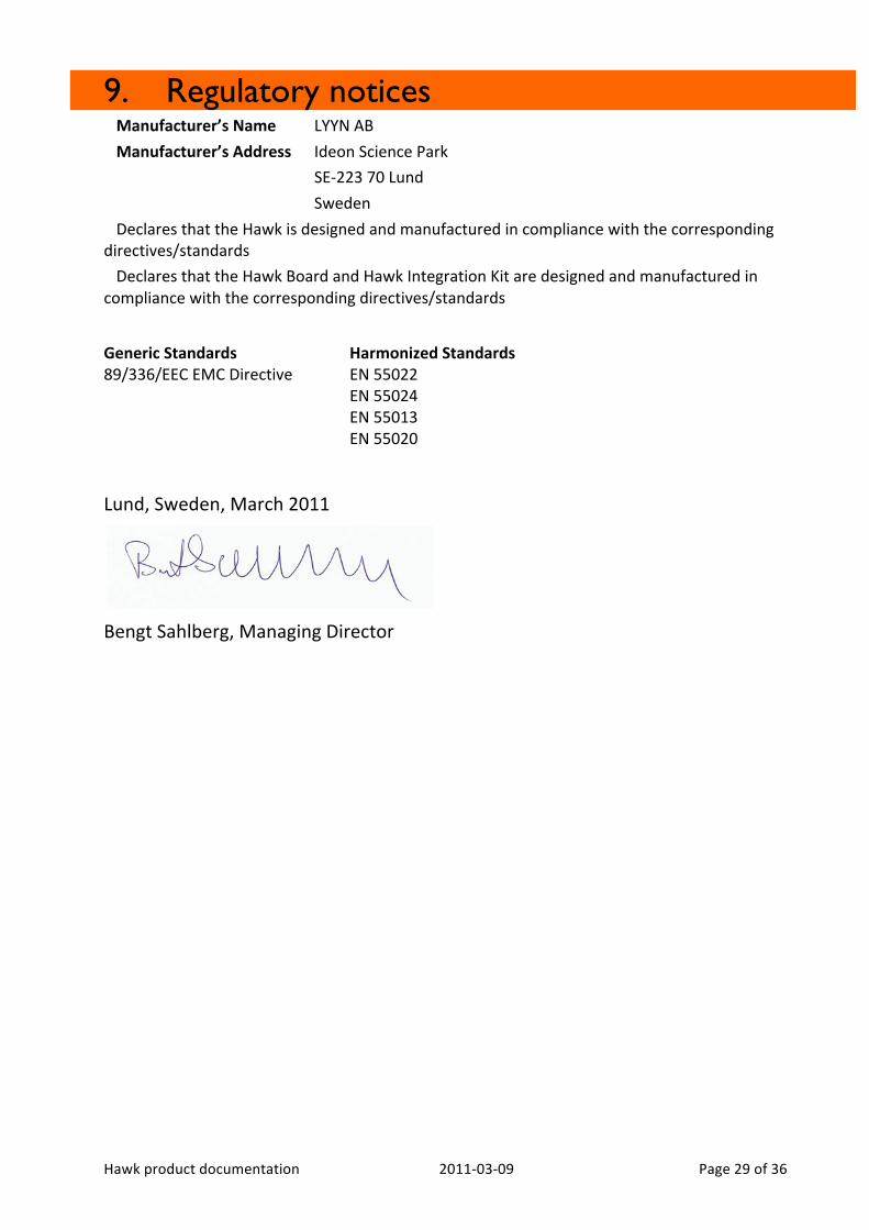
9. Regulatory notices Manufacturer’s Name LYYN AB Manufacturer’s Address Ideon Science Park SE-‐223 70 Lund Sweden Declares that the Hawk is designed and manufactured in compliance with the corresponding
directives/standards Declares that the Hawk Board and Hawk Integration Kit are designed and manufactured in
compliance with the corresponding directives/standards
Generic Standards Harmonized Standards 89/336/EEC EMC Directive EN 55022
EN 55024 EN 55013 EN 55020
Lund, Sweden, March 2011
Bengt Sahlberg, Managing Director
Hawk product documentation 2011-‐03-‐09 Page 30 of 36
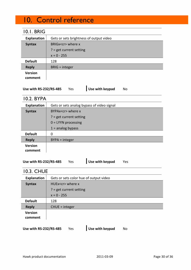
10. Control reference 10.1. BRIG Explanation Gets or sets brightness of output video Syntax BRIGx<cr> where x
? = get current setting x = 0 -‐ 255
Default 128 Reply BRIG = integer Version comment
Use with RS-‐232/RS-‐485 Yes Use with keypad No
10.2. BYPA Explanation Gets or sets analog bypass of video signal Syntax BYPAx<cr> where x
? = get current setting 0 = LYYN processing 1 = analog bypass
Default 0 Reply BYPA = integer Version comment
Use with RS-‐232/RS-‐485 Yes Use with keypad Yes
10.3. CHUE Explanation Gets or sets color hue of output video Syntax HUEx<cr> where x
? = get current setting x = 0 -‐ 255
Default 128 Reply CHUE = integer Version comment
Use with RS-‐232/RS-‐485 Yes Use with keypad No
Hawk product documentation 2011-‐03-‐09 Page 31 of 36
10.4. CONT Explanation Gets or sets contrast of output video Syntax CONTx<cr> where x
? = get current setting x = 0 -‐ 255
Default 128 Reply CONT = integer Version comment
Use with RS-‐232/RS-‐485 Yes Use with keypad No
10.5. INVE Explanation Toggles between a standard or inverted lyynification window Syntax INVEx<cr> where x
? = get current setting 0 = Standard window 1 = Inverted window
Default 0 Reply INVE = integer Version comment
Available from version 20100607 on HW rev D
Use with RS-‐232/RS-‐485 Yes Use with keypad Yes
10.6. LYYN Explanation Gets or sets the degree of lyynification Syntax LYYNx<cr> where x
? = get current setting 0 -‐ 9 = degree of lyynification 0 = no lyynification, 9 = max lyynification
Default 0 Reply LYYN = integer Version comment
Use with RS-‐232/RS-‐485 Yes Use with keypad Yes
Hawk product documentation 2011-‐03-‐09 Page 32 of 36
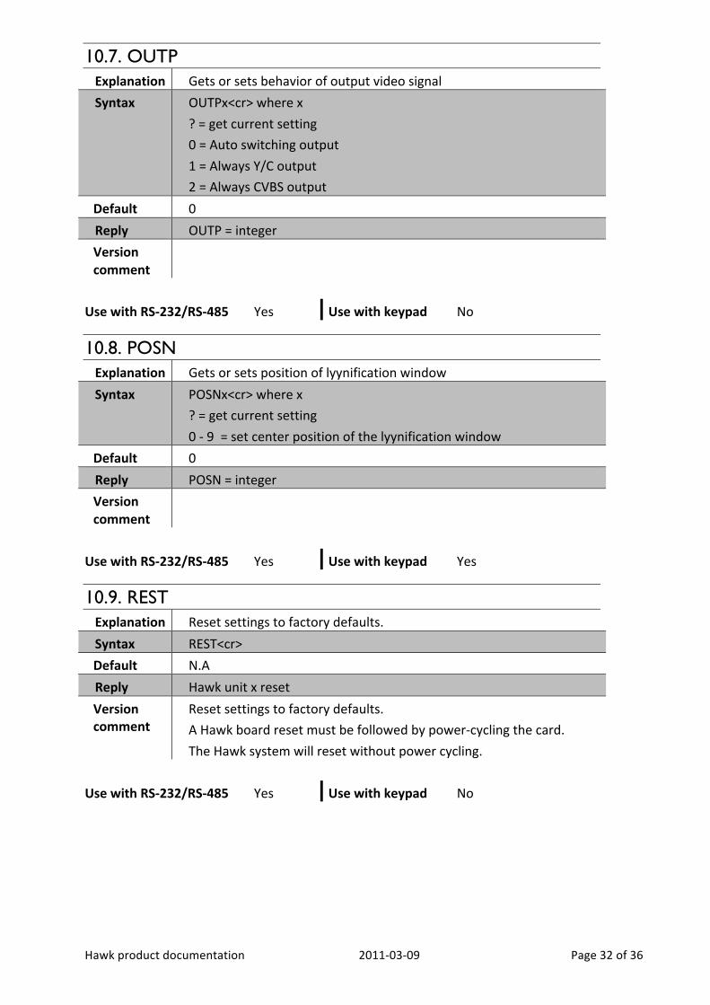
10.7. OUTP Explanation Gets or sets behavior of output video signal Syntax OUTPx<cr> where x
? = get current setting 0 = Auto switching output 1 = Always Y/C output 2 = Always CVBS output
Default 0 Reply OUTP = integer Version comment
Use with RS-‐232/RS-‐485 Yes Use with keypad No
10.8. POSN Explanation Gets or sets position of lyynification window Syntax POSNx<cr> where x
? = get current setting 0 -‐ 9 = set center position of the lyynification window
Default 0 Reply POSN = integer Version comment
Use with RS-‐232/RS-‐485 Yes Use with keypad Yes
10.9. REST Explanation Reset settings to factory defaults. Syntax REST<cr> Default N.A Reply Hawk unit x reset Version comment
Reset settings to factory defaults. A Hawk board reset must be followed by power-‐cycling the card. The Hawk system will reset without power cycling.
Use with RS-‐232/RS-‐485 Yes Use with keypad No
Hawk product documentation 2011-‐03-‐09 Page 33 of 36
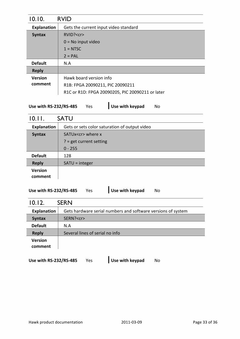
10.10. RVID Explanation Gets the current input video standard Syntax RVID?<cr>
0 = No input video 1 = NTSC 2 = PAL
Default N.A Reply Version comment
Hawk board version info R1B: FPGA 20090211, PIC 20090211 R1C or R1D: FPGA 20090205, PIC 20090211 or later
Use with RS-‐232/RS-‐485 Yes Use with keypad No
10.11. SATU Explanation Gets or sets color saturation of output video Syntax SATUx<cr> where x
? = get current setting 0 -‐ 255
Default 128 Reply SATU = integer Version comment
Use with RS-‐232/RS-‐485 Yes Use with keypad No
10.12. SERN Explanation Gets hardware serial numbers and software versions of system Syntax SERN?<cr> Default N.A Reply Several lines of serial no info Version comment
Use with RS-‐232/RS-‐485 Yes Use with keypad No
Hawk product documentation 2011-‐03-‐09 Page 34 of 36
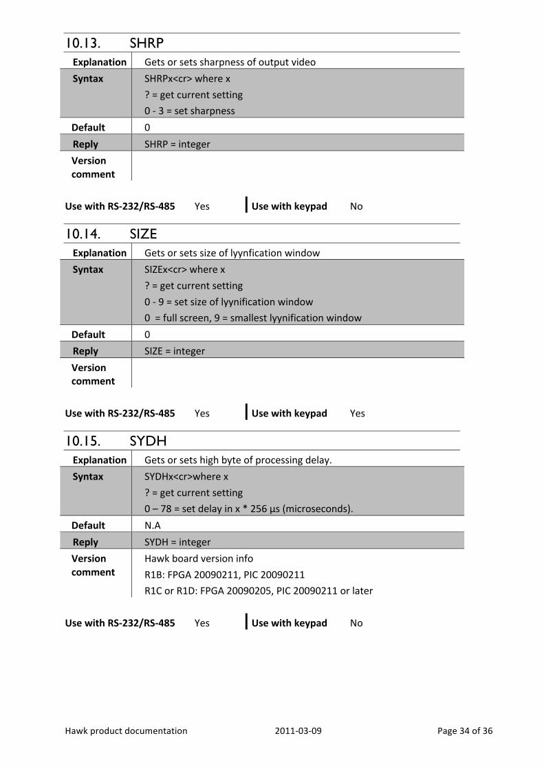
10.13. SHRP Explanation Gets or sets sharpness of output video Syntax SHRPx<cr> where x
? = get current setting 0 -‐ 3 = set sharpness
Default 0 Reply SHRP = integer Version comment
Use with RS-‐232/RS-‐485 Yes Use with keypad No
10.14. SIZE Explanation Gets or sets size of lyynfication window Syntax SIZEx<cr> where x
? = get current setting 0 -‐ 9 = set size of lyynification window 0 = full screen, 9 = smallest lyynification window
Default 0 Reply SIZE = integer Version comment
Use with RS-‐232/RS-‐485 Yes Use with keypad Yes
10.15. SYDH Explanation Gets or sets high byte of processing delay. Syntax SYDHx<cr>where x
? = get current setting 0 – 78 = set delay in x * 256 µs (microseconds).
Default N.A Reply SYDH = integer Version comment
Hawk board version info R1B: FPGA 20090211, PIC 20090211 R1C or R1D: FPGA 20090205, PIC 20090211 or later
Use with RS-‐232/RS-‐485 Yes Use with keypad No
Hawk product documentation 2011-‐03-‐09 Page 35 of 36
10.16. SYDL Explanation Gets or sets low byte of processing delay. Syntax SYDLx<cr> where x
? = get current setting 0 – 255 = set delay in x µs (microseconds).
Default N.A Reply SYDL = integer Version comment
Hawk board version info R1B: FPGA 20090211, PIC 20090211 R1C or R1D: FPGA 20090205, PIC 20090211 or later
Use with RS-‐232/RS-‐485 Yes Use with keypad No
10.17. SYNC Explanation Gets or sets synchronization mode. Syntax SYNCx<cr>where x
? = get current setting 0 = Normal mode. Synchronized/follows incoming video. The delay
approximately 140 µs 1 = External sync mode. Synchronized to signal at external sync input.
The delay is 1 frame + delay set with SYND command. 2 = Controlled delay (TBC) mode. Should be used in combination with
SYND, SYDH and SYDL commands. The delay is 140 µs + delay set with SYND command. Sync modes 1 and 2 can be used in combination with the SYND, SYDH
and SYDL commands. Default 0 Reply SYNC = integer Version comment
Hawk board version info SYNC0 and SYNC1 on all versions SYNC2 on the following versions R1B: FPGA 20090211, PIC 20090211 R1C or R1D: FPGA 20090205, PIC 20090211 or later
Use with RS-‐232/RS-‐485 Yes Use with keypad No
Hawk product documentation 2011-‐03-‐09 Page 36 of 36
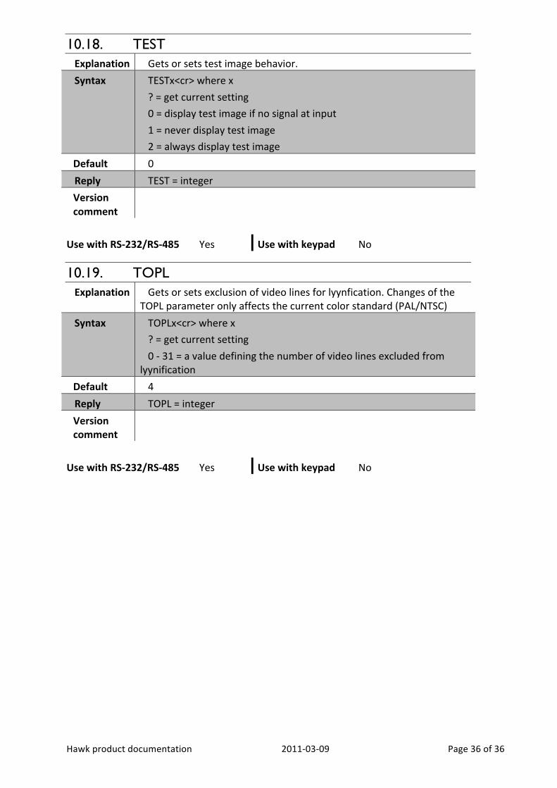
10.18. TEST Explanation Gets or sets test image behavior. Syntax TESTx<cr> where x
? = get current setting 0 = display test image if no signal at input 1 = never display test image 2 = always display test image
Default 0 Reply TEST = integer Version comment
Use with RS-‐232/RS-‐485 Yes Use with keypad No
10.19. TOPL Explanation Gets or sets exclusion of video lines for lyynfication. Changes of the
TOPL parameter only affects the current color standard (PAL/NTSC) Syntax TOPLx<cr> where x
? = get current setting 0 -‐ 31 = a value defining the number of video lines excluded from
lyynification Default 4 Reply TOPL = integer Version comment
Use with RS-‐232/RS-‐485 Yes Use with keypad No
Related Documents