CS REVISION TABLE NUMBER DATE REVISED BY DESCRIPTION SHEET: SCALE: T.M.P. 52-10-93 HECKLER TRACT WEST ROCKHILL TOWNSHIP BUCKS COUNTY 735 Minsi Trail Perkasie, PA 18944 Phone: 215-794-5391 Email: [email protected] DATE: AS NOTED SEAL Ridge Valley Road Residence LOT #3 RIDGE VALLEY RD A.P. ACCESS PANEL LIN LINEN LAMINATED VENEER LUMBER ORIENTED STRAND BOARD OVERFLOW SCUPPER OVERFLOW RAIN WATER CONDUCTOR OWNER FURNISHED OWNER INSTALLED RAIN WATER CONDUCTOR REINFORCED/REINFORCING UNLESS OTHERWISE NOTED UNDERWRITERS LABORATORIES VINYL COMPOSITE TILE POLYVINYL CHLORIDE PAPER TOWEL DISPENSER PENETRATION PLATE POWDER DRIVEN FASTENER SOLID CORE WHERE OCCURS WATER RESISTANT WORK POINT WATER PROOF WITHOUT VERTICAL VACUUM WAINSCOT WOOD WITH STORAGE SUSPENDED STRUCTURAL STORAGE STANDARD SQUARE STEEL SCHEDULE SQUARE FEET SPECIFICATION SIMILAR SHEET SHELVES SECTION SCHEDULE SINK ON CENTER POINT ROUGH OPENING 3/15/2017 ROUND REQUIRED RESISTANT RESILIENT ROOM REFRIGERATOR RECTANGULAR ROOF DRAIN RETURN AIR RADIUS PARTITION PANTRY PREFABRICATED PANEL PLYWOOD PEG BOARD PLATE OPENING OPTIONAL OPPOSITE OPENING OPPOSITE HAND MINIMUM NOT TO SCALE NOMINAL NUMBER NOT IN CONTRACT MICROLAM METAL MANUFACTURER MEDICINE CABINET MANUFACTURER MEMBRANE MECHANICAL MAXIMUM MATERIAL METAL LIGHT/LIGHTING LOW POINT FTG. FOOTING GYPSUM WALL BOARD GROSS SQUARE FEET GYPSUM WALL BOARD INT. GYP.BD. JT. J.B. INTER. INSUL. GYP. G.W.B. G.S.F. GRD. GL. GALV. GA. INTERIOR JUNCTION BOX INTERIOR INSULATION JOINT GROUND GYPSUM GALVANIZED GAUGE GLASS W.P.T. W.R. VERT. W.O. W.P. W/O WD. WANS. W/ STRUCT. U.O.N. V.C.T. VAC. STOR. U.L. SUSP. DTL. DETAIL PLYWD. FLUSH (FRAMING) FACE OF MASONRY FACE OF CONCRETE FINISHED OPENING FIRE EXTINGUISHER CABINET FIRE EXTINGUISHER EXTERIOR INSULATED FINISH SYSTEM EXPANSION JOINT FL FT. F.O.M. F.O.F. F.O.C. F.O. FLR. FLUOR. FLEX. FIXT. FIN. F.E.C. F.E. FDN. F.D. FAST. F.A. FLUORESCENT FOOT/FEET FACE OF FINISH FLOOR FLEXIBLE FIXTURE FINISH FOUNDATION FLOOR DRAIN FASTENED FIRE ALARM EXT. EXP. EXH. EXIST. EQUIP. EQ ENCL. ELEV. ELECT. ELEC. EL. E.J. E.I.F.S. EA. DW DWR. DWG. ELEVATION EXTERIOR EXPANSION EXHAUST EXISTING EQUIPMENT EQUAL ENCLOSURE ELECTRICAL EACH ELECTRICAL ELEVATION DISH WASHER DRAWER DRAWING S.F. SHLVS. STL. STG. STD. SQ. SPEC. SK. SIM. SHT. SCHED. S.C. SECT. SCH. R.W.C. R.O. RND R. REQ'D. RESIST. RM. RESIL. REINF. REF. REC. R.D. R.A. PREFAB. PT. PVC PTN. P.T.D. P.P. PNL. COUNTERTOP SEAM CONCRETE MASONRY UNIT CLEAR/CLEARANCE BOTTOM OF JOISTS CONTROL/CONSTRUCTION JOINT CONT. CS CONTR. DN. DISP. DIM. DIA. DEPT. CL CONC. C.O. CMU CLR. CLG. C.L. C.J. CONTINUOUS CONTRACTOR DISPENSER DIMENSION DIAMETER DEPARTMENT DOWN CEILING CONCRETE CLEAN OUT CLOSET CENTER LINE BLDG. BRKT. B.O.J. BLKG. C.I. CER. CEM. CAB. BDRM BETW BD. @ & BUILDING BRACKET BLOCKING CAST IRON CERAMIC CEMENT CABINET BEDROOM BETWEEN BOARD ANGLE AND AT NOM. O.R.W.C. PL. P.D.F. P.B. PAN. OSB OPT. O.S. O.F.O.J. O.C. OPNG OPP. OPN'G O.H. N.T.S. MEMB. MIN. MTL. NO. N.I.C. M.L. MET. MFR. MANUF. LVL M.C. MECH. MAX. MATL. LT. L.P. KNEE SPACE KICK PLATE LAVATORY LAMINATE ABOVE FINISHED FLOOR AIR CONDITIONING ALUM. A.F.F. ACOUST AC AB ALUMINUM ACOUSTICAL ANCHOR BOLT KS K.P. LAV. LAM. SHEET NO. INTERIOR ELEVATION ELEVATION NO. UA-3 2 1 3 VOID SPECIFICATION TAG 14 6 DETAIL ENLARGEMENT X-X SECTION NUMBER SHEET NUMBER XX X-X DIVISION ITEM NUMBER SHEET NO. BUILDING CORE & SHELL RIGID INSULATION WINDOW SYMBOL HORIZONTAL SIZE (FEET, INCHES) REVISION NUMBER DOOR SYMBOL VERTICAL SIZE (FEET, INCHES) 2 2868 ALUMINUM, ETC. METAL, BATT OR BLOWN BACKFILL EARTH: UNDISTURBED INSULATION EARTH: LIGHTWEIGHT CONCRETE CAST STONE CONCRETE CAST IN PLACE OR BRICK CONCRETE MASONRY UNIT PRE-CAST XX XX X-X DETAIL LARGE SCALE SMALL SCALE GLASS: DATUM ELEVATION FINISH CHANGE OF FLOOR C.T. CPT. FLAGSTONE OR SLATE CUT STONE, BLUESTONE, GRAVEL OR POROUS FILL SECTION NUMBER NUMBER SHEET NUMBER SECTION WOOD BLOCKING CERAMIC TILE: CERAMIC TILE: GLASS: AND PAD LARGE SCALE PROFILE PLYWOOD: LARGE SCALE CARPET STONE: ROUGH-CUT OR RUBBLE WOOD: FINISH WOOD: ROUGH RESILIANT FLOORING PLASTER CEMENT, CRUSHED STONE, SAND, GROUT STONE ROCK OR STUCCO REINFORCED STEEL METAL: SMALL SCALE SMALL SCALE WALL BOARD GYPSUM PLYWOOD: = 300 POUNDS / 4 SQUARE INCHES AT CENTER = 60 P.S.F. (LIVE LOAD) + 10 P.S.F. (DEAD LOAD) = 40 P.S.F. (LIVE LOAD) + 10 P.S.F. (DEAD LOAD) = 40 P.S.F. (LIVE LOAD) + 10 P.S.F. (DEAD LOAD) = 30 P.S.F. (LIVE LOAD) + 10 P.S.F. (DEAD LOAD) = 20 P.S.F. (LIVE LOAD) + 10 P.S.F. (DEAD LOAD) = 50 P.S.F. (LIVE LOAD) + 50 P.S.F. (DEAD LOAD) = 20 P.S.F. (LIVE LOAD) + 10 P.S.F. (DEAD LOAD) = 1150 PSI (REPETITIVE MEMBER USAGE) = 2000 POUNDS / 20 SQUARE INCHES WIND LOAD IMPORTANCE FACTOR (I) = 1.00 * WIND DESIGN PRESSURE (P) * FOR ALL WALLS AND ROOF (ANY WIND DIRECTION) WINDWARD OR LEEWARD WIND EXPOSURE CATEGORY WIND DIRECTION = 10 P.S.F. = EXPOSURE B = VARIES F .9500 .8282 .7550 .5000 .6875 ROOF SLOPE FACTOR (C ) SLOPED ROOF SNOW LOAD (P ) GROUND SNOW LOAD ( P ) FLAT ROOF SNOW LOAD (P ) SNOW EXPOSURE FACTURE (C ) SNOW IMPORTANCE FACTOR (I) WIND LOADS 7.5:12 9:12 10:12 12:12 11:12 BASIC WIND SPEED MAX. TOTAL LOAD DEFLECTION ALLOWED DEFLECTION ALLOWED MAX. LIVE LOAD SNOW LOADS MICROLAM = b F b = 0.7 Abbreviations = 90 M.P.H. 15.9 10.5 14.4 = 1.00 19.9 17.4 = L/360 (HABITABLE SPACE) = L/240 (ROOF) Architectural Symbols = 2925 PSI = 30 P.S.F. = 21 P.S.F. CONCENTRATED LOAD DESIGN VALUES UNIFORMLY DISTRIBUTED LOAD DESIGN VALUES F DESIGN VALUES WHIRLPOOL TUB LUMBER = PARALLAM = GARAGE FLOOR STAIR TREADS b ROOF b F SLEEPING ROOMS GARAGE DECKS FIRST FLOOR SECOND FLOOR ATTIC = 55 POUNDS PER SQUARE FOOT = 2900 PSI OF TREAD P.S.F. P.S.F. P.S.F. P.S.F. P.S.F. Load Calculations CS COVER SHEET A-1 FOUNDATION PLAN A-2 FIRST FLOOR PLAN A-3 SECOND FLOOR PLAN A-4 EXTERIOR ELEVATIONS A-5 FRAMING PLAN A-6 FRAMING PLAN (CON'T) A-7 LVL FASTENING SCHEDULE A-8 TYPICAL WALL SECTION A-9 GENERAL CONSTRUCTION NOTES P-1 PLUMBING PLAN E-1 FOUNDATION, FIRST & SECOND FLOOR ELECTRICAL PLAN H-1 FOUNDATION, FIRST & SECOND FLOOR HVAC PLAN 1146 S.F. * SECOND FLOOR: * TOTAL LIVABLE: 2295 S.F. GARAGE: SPACE * FIRST FLOOR: AREA (S.F.) 435 S.F. 1149 S.F. BASEMENT: 1213 S.F. Square Footages Drawing List Contact Persons Construction Information BUILDER LYNN BUILDERS LLC STEPHEN C. YATES, P.E. LOCATION: USE GROUP: CONSTRUCTION TYPE: PROJECT NUMBER: APPLICABLE CODE: ISSUE DATE: REVISED:

Welcome message from author
This document is posted to help you gain knowledge. Please leave a comment to let me know what you think about it! Share it to your friends and learn new things together.
Transcript
CS
RE
VIS
ION
TA
BL
EN
UM
BE
RD
AT
ER
EV
ISE
D B
YD
ES
CR
IPT
ION
SHEET:
SCALE:
T.M
.P.
52
-10
-93
HE
CK
LE
R T
RA
CT
WE
ST
RO
CK
HIL
L T
OW
NS
HIP
BU
CK
S C
OU
NT
Y
73
5 M
insi T
rail
Pe
rka
sie
, P
A 1
89
44
Ph
on
e: 2
15
-79
4-5
39
1E
ma
il:in
fo@
lyn
nb
uild
ers
llc.c
om
DATE:
AS NOTED
SE
AL
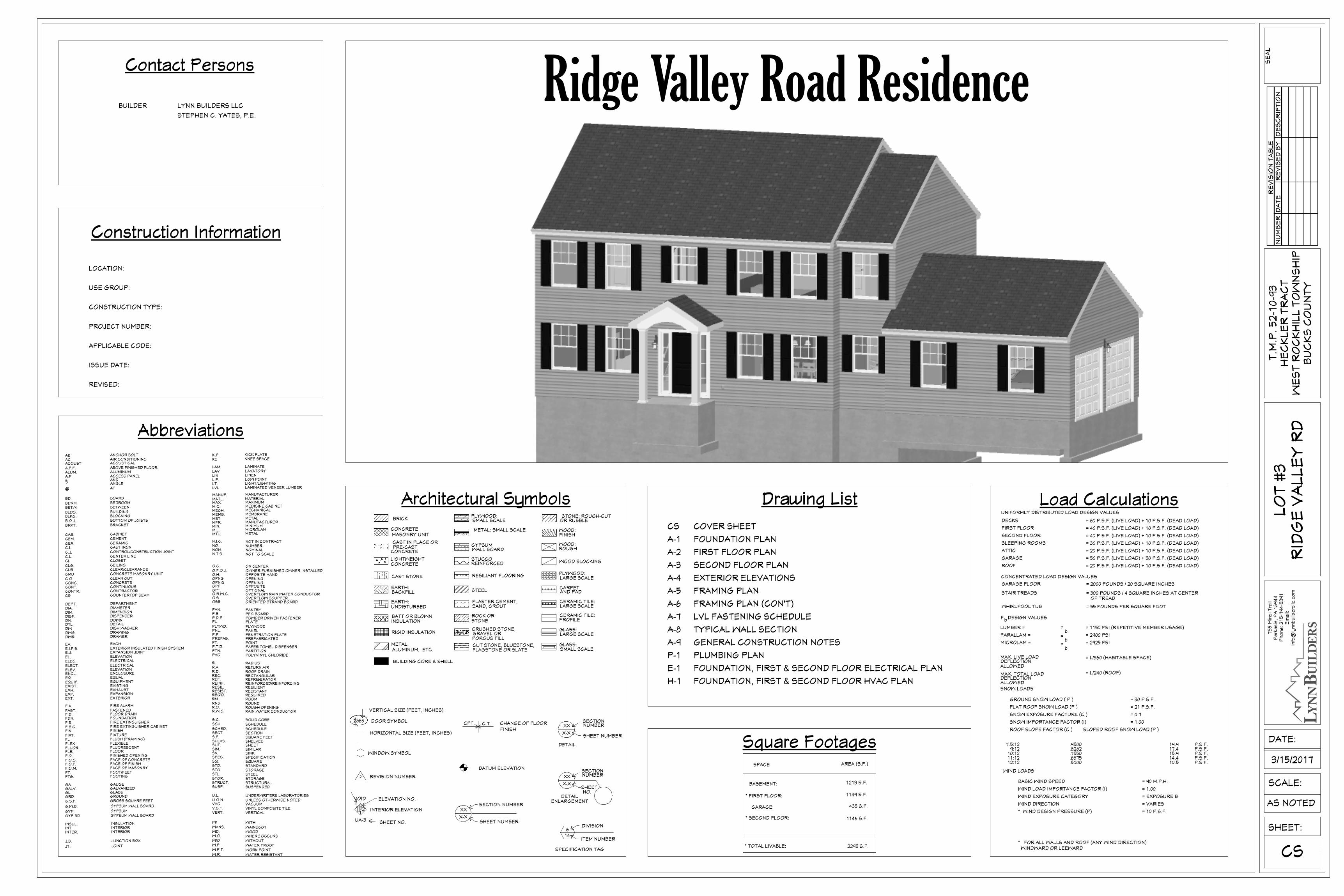
Ridge Valley Road Residence
LO
T #
3R
IDG
E V
AL
LE
Y R
D
A.P. ACCESS PANEL LIN LINEN
LAMINATED VENEER LUMBER
ORIENTED STRAND BOARDOVERFLOW SCUPPEROVERFLOW RAIN WATER CONDUCTOR
OWNER FURNISHED OWNER INSTALLED
RAIN WATER CONDUCTOR
REINFORCED/REINFORCING
UNLESS OTHERWISE NOTEDUNDERWRITERS LABORATORIES
VINYL COMPOSITE TILE
POLYVINYL CHLORIDE
PAPER TOWEL DISPENSER
PENETRATION PLATE
POWDER DRIVEN FASTENER
SOLID CORE
WHERE OCCURS
WATER RESISTANTWORK POINTWATER PROOFWITHOUT
VERTICAL
VACUUM
WAINSCOTWOOD
WITH
STORAGE
SUSPENDEDSTRUCTURAL
STORAGESTANDARDSQUARE
STEEL
SCHEDULE
SQUARE FEET
SPECIFICATION
SIMILARSHEETSHELVES
SECTION
SCHEDULE
SINK
ON CENTER
POINT
ROUGH OPENING
3/15/2017
ROUND
REQUIREDRESISTANTRESILIENT
ROOM
REFRIGERATORRECTANGULARROOF DRAINRETURN AIRRADIUS
PARTITION
PANTRY
PREFABRICATED
PANELPLYWOOD
PEG BOARD
PLATE
OPENING
OPTIONALOPPOSITEOPENING
OPPOSITE HAND
MINIMUM
NOT TO SCALENOMINALNUMBERNOT IN CONTRACT
MICROLAMMETAL
MANUFACTURER
MEDICINE CABINET
MANUFACTURER
MEMBRANEMECHANICAL
MAXIMUMMATERIAL
METAL
LIGHT/LIGHTINGLOW POINT
FTG. FOOTING
GYPSUM WALL BOARD
GROSS SQUARE FEET
GYPSUM WALL BOARD
INT.
GYP.BD.
JT.
J.B.
INTER.
INSUL.
GYP.
G.W.B.
G.S.F.GRD.GL.GALV.GA.
INTERIOR
JUNCTION BOX
INTERIOR
INSULATION
JOINT
GROUND
GYPSUM
GALVANIZEDGAUGE
GLASS
W.P.T.W.R.
VERT.
W.O.
W.P.W/O
WD.WANS.W/
STRUCT.
U.O.N.
V.C.T.VAC.
STOR.
U.L.
SUSP.
DTL. DETAILPLYWD.
FLUSH (FRAMING)
FACE OF MASONRY
FACE OF CONCRETEFINISHED OPENING
FIRE EXTINGUISHER CABINETFIRE EXTINGUISHER
EXTERIOR INSULATED FINISH SYSTEMEXPANSION JOINT
FL
FT.F.O.M.F.O.F.F.O.C.F.O.FLR.FLUOR.FLEX.
FIXT.FIN.F.E.C.F.E.FDN.F.D.FAST.F.A.
FLUORESCENT
FOOT/FEET
FACE OF FINISH
FLOOR
FLEXIBLE
FIXTUREFINISH
FOUNDATIONFLOOR DRAINFASTENEDFIRE ALARM
EXT.EXP.EXH.EXIST.EQUIP.EQENCL.ELEV.ELECT.ELEC.EL.E.J.E.I.F.S.EA.
DW
DWR.DWG.
ELEVATION
EXTERIOREXPANSIONEXHAUSTEXISTINGEQUIPMENTEQUALENCLOSURE
ELECTRICAL
EACH
ELECTRICALELEVATION
DISH WASHER
DRAWERDRAWING
S.F.SHLVS.
STL.STG.STD.SQ.SPEC.SK.SIM.SHT.
SCHED.
S.C.
SECT.
SCH.
R.W.C.R.O.RND
R.
REQ'D.RESIST.
RM.
RESIL.REINF.REF.REC.R.D.R.A.
PREFAB.PT.
PVCPTN.P.T.D.
P.P.PNL.
COUNTERTOP SEAM
CONCRETE MASONRY UNITCLEAR/CLEARANCE
BOTTOM OF JOISTS
CONTROL/CONSTRUCTION JOINT
CONT.
CSCONTR.
DN.DISP.DIM.DIA.DEPT.
CL
CONC.C.O.CMUCLR.CLG.
C.L.C.J.
CONTINUOUSCONTRACTOR
DISPENSERDIMENSIONDIAMETERDEPARTMENT
DOWN
CEILING
CONCRETECLEAN OUT
CLOSETCENTER LINE
BLDG.
BRKT.B.O.J.BLKG.
C.I.CER.CEM.CAB.
BDRMBETW
BD.
@
&
BUILDING
BRACKET
BLOCKING
CAST IRONCERAMICCEMENTCABINET
BEDROOMBETWEEN
BOARD
ANGLEAND
AT
NOM.
O.R.W.C.
PL.P.D.F.P.B.PAN.
OSB
OPT.
O.S.
O.F.O.J.O.C.
OPNG
OPP.OPN'G
O.H.
N.T.S.
MEMB.
MIN.
MTL.
NO.N.I.C.
M.L.
MET.MFR.
MANUF.
LVL
M.C.MECH.
MAX.MATL.
LT.L.P.
KNEE SPACEKICK PLATE
LAVATORYLAMINATEABOVE FINISHED FLOOR
AIR CONDITIONING
ALUM.A.F.F.ACOUSTACAB
ALUMINUM
ACOUSTICAL
ANCHOR BOLTKSK.P.
LAV.LAM.
SHEET NO.
INTERIOR ELEVATION
ELEVATION NO.
UA-3
213
VOID
SPECIFICATION TAG
146
DETAILENLARGEMENT
X-X
SECTION NUMBER
SHEET NUMBER
XX
X-X
DIVISION
ITEM NUMBER
SHEETNO.
BUILDING CORE & SHELL
RIGID INSULATION
WINDOW SYMBOL
HORIZONTAL SIZE (FEET, INCHES)
REVISION NUMBER
DOOR SYMBOL
VERTICAL SIZE (FEET, INCHES)
2
2868
ALUMINUM, ETC.METAL,
BATT OR BLOWN
BACKFILL
EARTH:UNDISTURBED
INSULATION
EARTH:
LIGHTWEIGHTCONCRETE
CAST STONE
CONCRETE
CAST IN PLACE OR
BRICK
CONCRETEMASONRY UNIT
PRE-CAST
XX
XX
X-X
DETAIL
LARGE SCALE
SMALL SCALEGLASS:
DATUM ELEVATION
FINISHCHANGE OF FLOORC.T.CPT.
FLAGSTONE OR SLATECUT STONE, BLUESTONE,
GRAVEL OR POROUS FILL
SECTIONNUMBER
NUMBER
SHEET NUMBER
SECTION
WOOD BLOCKING
CERAMIC TILE:
CERAMIC TILE:
GLASS:
AND PAD
LARGE SCALE
PROFILE
PLYWOOD:LARGE SCALE
CARPET
STONE: ROUGH-CUTOR RUBBLE
WOOD:FINISH
WOOD:ROUGH
RESILIANT FLOORING
PLASTER CEMENT,
CRUSHED STONE,
SAND, GROUT
STONEROCK OR
STUCCOREINFORCED
STEEL
METAL: SMALL SCALE
SMALL SCALE
WALL BOARDGYPSUM
PLYWOOD:
= 300 POUNDS / 4 SQUARE INCHES AT CENTER
= 60 P.S.F. (LIVE LOAD) + 10 P.S.F. (DEAD LOAD)
= 40 P.S.F. (LIVE LOAD) + 10 P.S.F. (DEAD LOAD)
= 40 P.S.F. (LIVE LOAD) + 10 P.S.F. (DEAD LOAD)
= 30 P.S.F. (LIVE LOAD) + 10 P.S.F. (DEAD LOAD)
= 20 P.S.F. (LIVE LOAD) + 10 P.S.F. (DEAD LOAD)
= 50 P.S.F. (LIVE LOAD) + 50 P.S.F. (DEAD LOAD)
= 20 P.S.F. (LIVE LOAD) + 10 P.S.F. (DEAD LOAD)
= 1150 PSI (REPETITIVE MEMBER USAGE)
= 2000 POUNDS / 20 SQUARE INCHES
WIND LOAD IMPORTANCE FACTOR (I) = 1.00
* WIND DESIGN PRESSURE (P)
* FOR ALL WALLS AND ROOF (ANY WIND DIRECTION) WINDWARD OR LEEWARD
WIND EXPOSURE CATEGORY
WIND DIRECTION
= 10 P.S.F.
= EXPOSURE B
= VARIES
F
.9500
.8282
.7550
.5000
.6875
ROOF SLOPE FACTOR (C ) SLOPED ROOF SNOW LOAD (P )
GROUND SNOW LOAD ( P )
FLAT ROOF SNOW LOAD (P )
SNOW EXPOSURE FACTURE (C )
SNOW IMPORTANCE FACTOR (I)
WIND LOADS
7.5:129:12
10:12
12:12 11:12
BASIC WIND SPEED
MAX. TOTAL LOAD
DEFLECTIONALLOWED
DEFLECTIONALLOWED
MAX. LIVE LOAD
SNOW LOADS
MICROLAM =b
Fb
= 0.7
Abbreviations
= 90 M.P.H.
15.9
10.514.4
= 1.00
19.917.4
= L/360 (HABITABLE SPACE)
= L/240 (ROOF)
Architectural Symbols
= 2925 PSI
= 30 P.S.F.
= 21 P.S.F.
CONCENTRATED LOAD DESIGN VALUES
UNIFORMLY DISTRIBUTED LOAD DESIGN VALUES
F DESIGN VALUES
WHIRLPOOL TUB
LUMBER =
PARALLAM =
GARAGE FLOOR
STAIR TREADS
b
ROOF
bF
SLEEPING ROOMS
GARAGE
DECKS
FIRST FLOOR
SECOND FLOOR
ATTIC
= 55 POUNDS PER SQUARE FOOT
= 2900 PSI
OF TREAD
P.S.F.
P.S.F.P.S.F.
P.S.F.P.S.F.
Load Calculations
CS COVER SHEET
A-1 FOUNDATION PLAN
A-2 FIRST FLOOR PLAN
A-3 SECOND FLOOR PLAN
A-4 EXTERIOR ELEVATIONS
A-5 FRAMING PLAN
A-6 FRAMING PLAN (CON'T)
A-7 LVL FASTENING SCHEDULE
A-8 TYPICAL WALL SECTION
A-9 GENERAL CONSTRUCTION NOTES
P-1 PLUMBING PLAN
E-1 FOUNDATION, FIRST & SECOND FLOOR ELECTRICAL PLAN
H-1 FOUNDATION, FIRST & SECOND FLOOR HVAC PLAN
1146 S.F.* SECOND FLOOR:
* TOTAL LIVABLE: 2295 S.F.
GARAGE:
SPACE
* FIRST FLOOR:
AREA (S.F.)
435 S.F.
1149 S.F.
BASEMENT: 1213 S.F.
Square Footages
Drawing List
Contact Persons
Construction Information
BUILDER LYNN BUILDERS LLC
STEPHEN C. YATES, P.E.
LOCATION:
USE GROUP:
CONSTRUCTION TYPE:
PROJECT NUMBER:
APPLICABLE CODE:
ISSUE DATE:
REVISED:
WH
2810AW
404
0LS
UP
5'-1
"
13'-5 1/2" 7' 13'-5 1/2"
29'-5 1/2" 4'-5 1/2"
22'-6
1/2
"7
'-5
1/2
"
9'-8"
38'-8 1/2"
11'-6 1/2"
2'
3'-1"
3'-1
1 1
/2"
14'-7
"1
3'-9
"
23'-0
1/2
"
9'-8" 9'-8" 9'-8"
30'
61'
33'-11" 6'-5 1/2" 20'-7 1/2"
3'-3
1/2
"5
'-8
1/2
"2
1'
61'
20'-4"6'-9"33'-11"
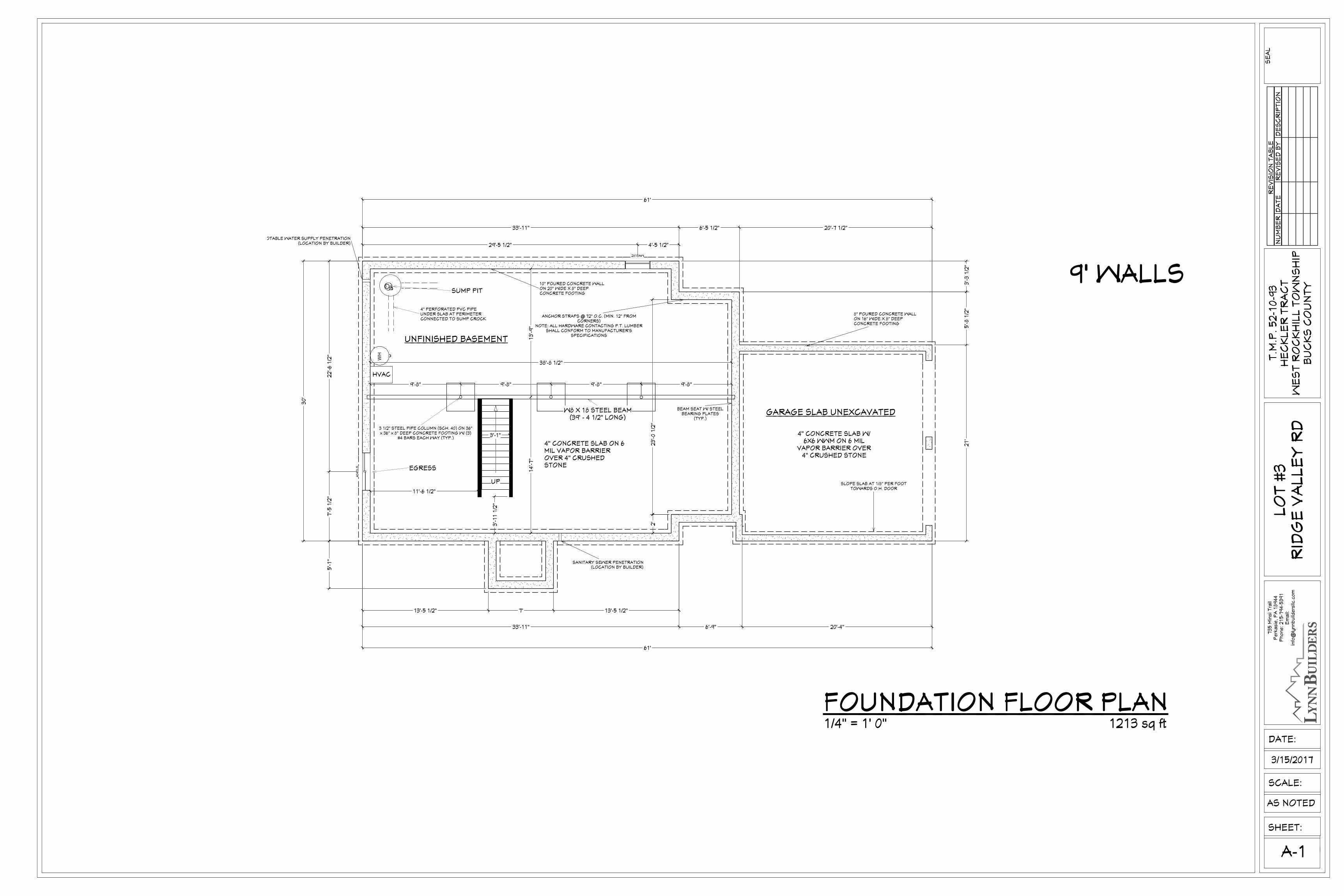
SUMP PIT
UNFINISHED BASEMENT
GARAGE SLAB UNEXCAVATED
4" CONCRETE SLAB ON 6MIL VAPOR BARRIEROVER 4" CRUSHEDSTONE
4" CONCRETE SLAB W/6X6 WWM ON 6 MIL
VAPOR BARRIER OVER4" CRUSHED STONE
W8 X 18 STEEL BEAM(39' - 4 1/2" LONG)
10" POURED CONCRETE WALLON 20" WIDE X 8" DEEPCONCRETE FOOTING
8" POURED CONCRETE WALLON 16" WIDE X 8" DEEPCONCRETE FOOTING
4" PERFORATED PVC PIPEUNDER SLAB AT PERIMETERCONNECTED TO SUMP CROCK
POTABLE WATER SUPPLY PENETRATION(LOCATION BY BUILDER)
SANITARY SEWER PENETRATION(LOCATION BY BUILDER)
HVAC
ANCHOR STRAPS @ 72" O.C. (MIN. 12" FROMCORNERS)
NOTE: ALL HARDWARE CONTACTING P.T. LUMBERSHALL CONFORM TO MANUFACTURER'S
SPECIFICATIONS
3 1/2" STEEL PIPE COLUMN (SCH. 40) ON 36"x 36" x 8" DEEP CONCRETE FOOTING W/ (3)
#4 BARS EACH WAY (TYP.)
BEAM SEAT W/ STEELBEARING PLATES
(TYP.)
EGRESS
SLOPE SLAB AT 1/8" PER FOOTTOWARDS O.H. DOOR
RE
VIS
ION
TA
BL
EN
UM
BE
RD
AT
ER
EV
ISE
D B
YD
ES
CR
IPT
ION
SHEET:
A-1
SCALE:
T.M
.P.
52
-10
-93
HE
CK
LE
R T
RA
CT
WE
ST
RO
CK
HIL
L T
OW
NS
HIP
BU
CK
S C
OU
NT
Y
73
5 M
insi T
rail
Pe
rka
sie
, P
A 1
89
44
Ph
on
e: 2
15
-79
4-5
39
1E
ma
il:in
fo@
lyn
nb
uild
ers
llc.c
om
DATE:
AS NOTED
SE
AL
LO
T #
3R
IDG
E V
AL
LE
Y R
D
3/15/2017
1213 sq ft
9' WALLS
FOUNDATION FLOOR PLAN1/4" = 1' 0"
DN
SB3636
B183
6L
B1836L
B303
6
B4836
B4836
SB3636
B183
6L
B1836L
B303
6
B4836
B4836
W362424
W3024
W4842
W3042
W3042
DCW2442LW3342
3056SH 3056SH 6068 3030SH
3040SH
30
68
24
68
30
68
80
70
80
70
2040SH
2268
3056SH3056SH
2868
24
68
24
68
60
68
6068 2468 4168 3068
36
68
3056SH3056SH5468MU3056SH3056SH
36
30
UP
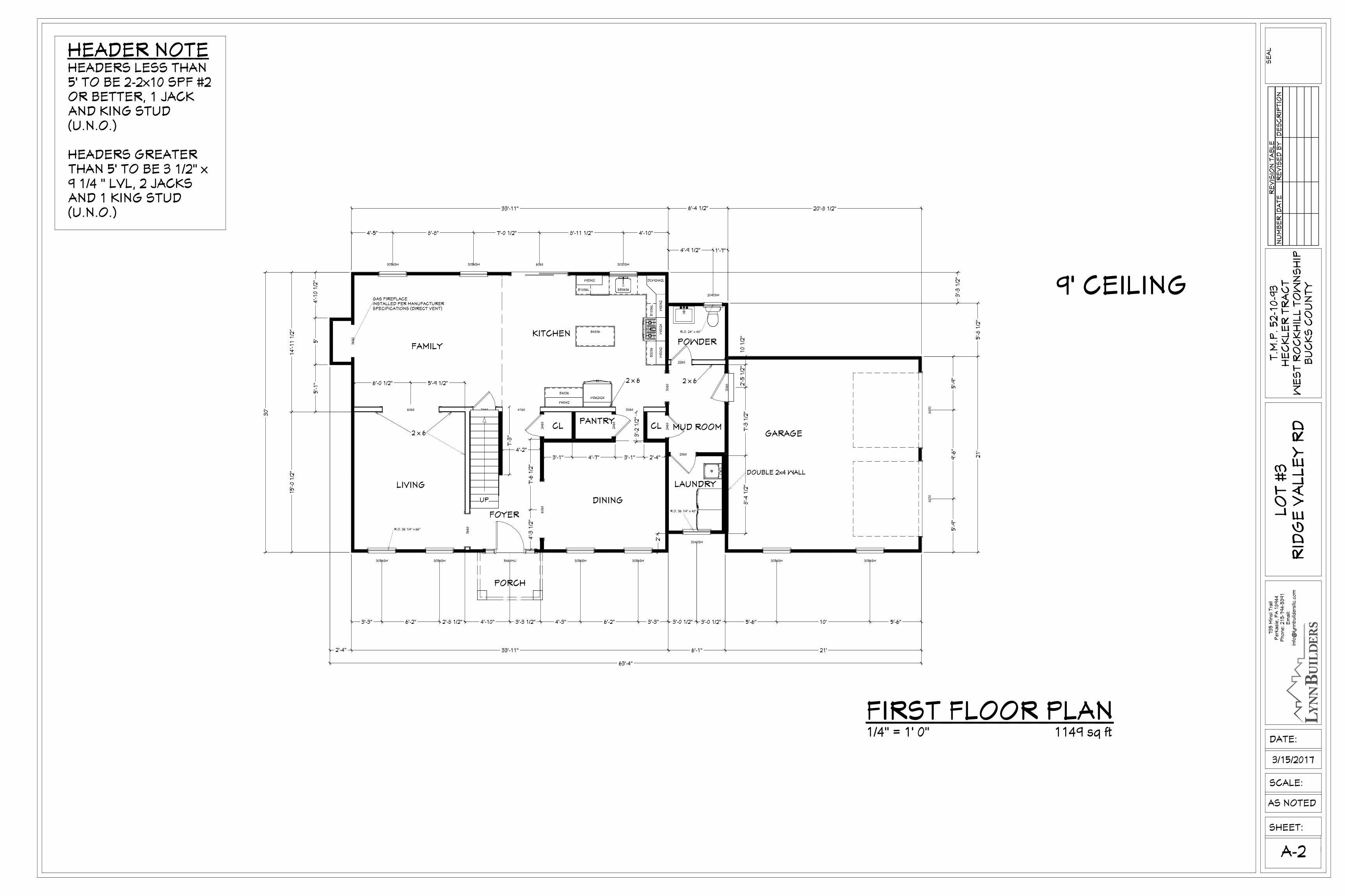
GAS FIREPLACEINSTALLED PER MANUFACTURER SPECIFICATIONS (DIRECT VENT)
5'-6"10'5'-6"3'-0 1/2"3'-3" 6'-2" 2'-8 1/2" 4'-10" 3'-3 1/2" 4'-3" 6'-2" 3'-3" 3'-0 1/2"
5'-9
"9
'-6
"5
'-9
"
14
'-1
1 1
/2"
15
'-0
1/2
"
8'-4
1/2
"7
'-3
1/2
"2
'-5
1/2
"1
0 1
/2"
4'-2"
3'-2
1/2
"
3'-1" 4'-7" 3'-1" 2'-4"
4'-9 1/2" 1'-7"
4'-5" 8'-8" 7'-0 1/2" 8'-11 1/2" 4'-10"
7'-3
"
4'-3
1/2
"7
'-6
1/2
"
6'-0 1/2" 5'-9 1/2"
3'-3
1/2
"
30
'
5'-1
"5
'4
'-1
0 1
/2"
2'
5'-8
1/2
"2
1'
33'-11" 6'-4 1/2" 20'-8 1/2"
63'-4"
21'6'-1"33'-11"2'-4"
GARAGE
DINING
LIVING
FAMILY
KITCHEN
MUD ROOM
POWDER
R.O. 36 1/4" x 66"
R.O. 24" x 48"
R.O. 36 1/4" x 48"
2 x 6
PORCH
DOUBLE 2x4 WALL
PANTRYKIT CHEN
LAUNDRY
CL CL
2 x 6
2 x 6
FOYER
HEADER NOTEHEADERS LESS THAN5' TO BE 2-2x10 SPF #2OR BETTER, 1 JACKAND KING STUD(U.N.O.)
HEADERS GREATERTHAN 5' TO BE 3 1/2" x9 1/4 " LVL, 2 JACKSAND 1 KING STUD(U.N.O.)
RE
VIS
ION
TA
BL
EN
UM
BE
RD
AT
ER
EV
ISE
D B
YD
ES
CR
IPT
ION
A-2
SHEET:
SCALE:
T.M
.P.
52
-10
-93
HE
CK
LE
R T
RA
CT
WE
ST
RO
CK
HIL
L T
OW
NS
HIP
BU
CK
S C
OU
NT
Y
73
5 M
insi T
rail
Pe
rka
sie
, P
A 1
89
44
Ph
on
e: 2
15
-79
4-5
39
1E
ma
il:in
fo@
lyn
nb
uild
ers
llc.c
om
DATE:
AS NOTED
SE
AL
LO
T #
3R
IDG
E V
AL
LE
Y R
D
3/15/2017
1149 sq ft
9' CEILING
FIRST FLOOR PLAN1/4" = 1' 0"
DN
SB
3036
SB
3036
SB
3636
SB
3636
SB
3036
SB
3036
SB
3636
SB
3636
5068
306
8
3050SH
3050SH3050SH3040SH3050SH3050SH
3050SH 3050SH 2640SH
2868
24685068 2868
2668
206
8
2668
2868
286
8
2868
466
8
4'-4 1/2"
6'-1
1 1
/2"
2'-5
1/2
"9
'-8
1/2
"
6'-10"
3'-8" 2'-1"
3'-1"
2'-9
1/2
"
8'-1
"3
'-8
1/2
"
5'-1
1/2
"6
'-4
1/2
"
1'-7"3'-6 1/2"3'-3 1/2"
1'-6 1/2"
5'-1
1"
3'-7
"
9'-11"
10'-5
"
4'-2"1'-8"1'-11"
4'-0 1/2"
3'-6 1/2"
11'-7" 14'-3 1/2" 3'-8" 4'-4 1/2" 6'-4 1/2"
8'-7" 3' 11'-3 1/2" 3'1'-8 1/2"
1'-11 1/2"
30'
11'-9
1/2
"
2'-3
1/2
"2
'-3
1/2
"
13'-7
1/2
"
3'-3
1/2
"1
5'-1
1/2
"9
'-7
"2
'
40'-3 1/2"
6'-4 1/2"12'-1 1/2"9'-1 1/2"12'-8"
3'-4"3'-0 1/2"
3'-3"6'-2"2'-8 1/2"4'-9 1/2"4'-4"3'-3"6'-2"3'-3"
135°
135°
135°
135°
135°
135°
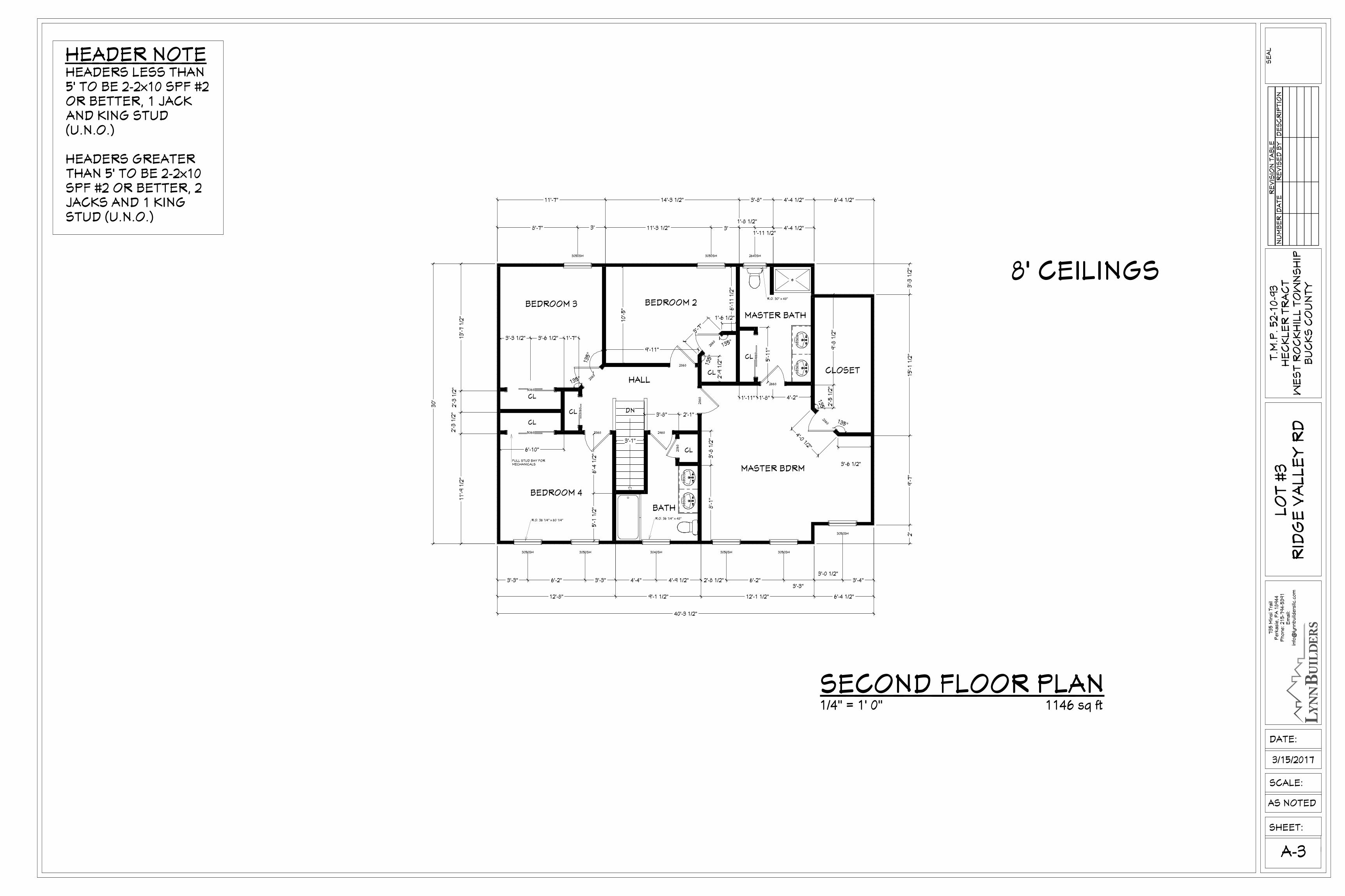
MASTER BDRM
CL CLOSET
BEDROOM 2BEDROOM 3
BEDROOM 4
HALL
BATH
CL
FULL STUD BAY FORMECHANICALS
R.O. 36 1/4" x 60 1/4" R.O. 36 1/4" x 48"
R.O. 30" x 48"
MASTER BATH
CL
CL
CL
CL
HEADER NOTEHEADERS LESS THAN5' TO BE 2-2x10 SPF #2OR BETTER, 1 JACKAND KING STUD(U.N.O.)
HEADERS GREATERTHAN 5' TO BE 2-2x10SPF #2 OR BETTER, 2JACKS AND 1 KINGSTUD (U.N.O.)
RE
VIS
ION
TA
BL
EN
UM
BE
RD
AT
ER
EV
ISE
D B
YD
ES
CR
IPT
ION
SHEET:
SCALE:
A-3
T.M
.P.
52
-10
-93
HE
CK
LE
R T
RA
CT
WE
ST
RO
CK
HIL
L T
OW
NS
HIP
BU
CK
S C
OU
NT
Y
73
5 M
insi T
rail
Pe
rka
sie
, P
A 1
89
44
Ph
on
e: 2
15
-79
4-5
39
1E
ma
il:in
fo@
lyn
nb
uild
ers
llc.c
om
DATE:
AS NOTED
SE
AL
LO
T #
3R
IDG
E V
AL
LE
Y R
D
3/15/2017
1146 sq ft
8' CEILINGS
SECOND FLOOR PLAN1/4" = 1' 0"
44"
RE
VIS
ION
TA
BL
EN
UM
BE
RD
AT
ER
EV
ISE
D B
YD
ES
CR
IPT
ION
SHEET:
SCALE:
A-4
T.M
.P.
52
-10
-93
HE
CK
LE
R T
RA
CT
WE
ST
RO
CK
HIL
L T
OW
NS
HIP
BU
CK
S C
OU
NT
Y
73
5 M
insi T
rail
Pe
rka
sie
, P
A 1
89
44
Ph
on
e: 2
15
-79
4-5
39
1E
ma
il:in
fo@
lyn
nb
uild
ers
llc.c
om
DATE:
AS NOTED
SE
AL
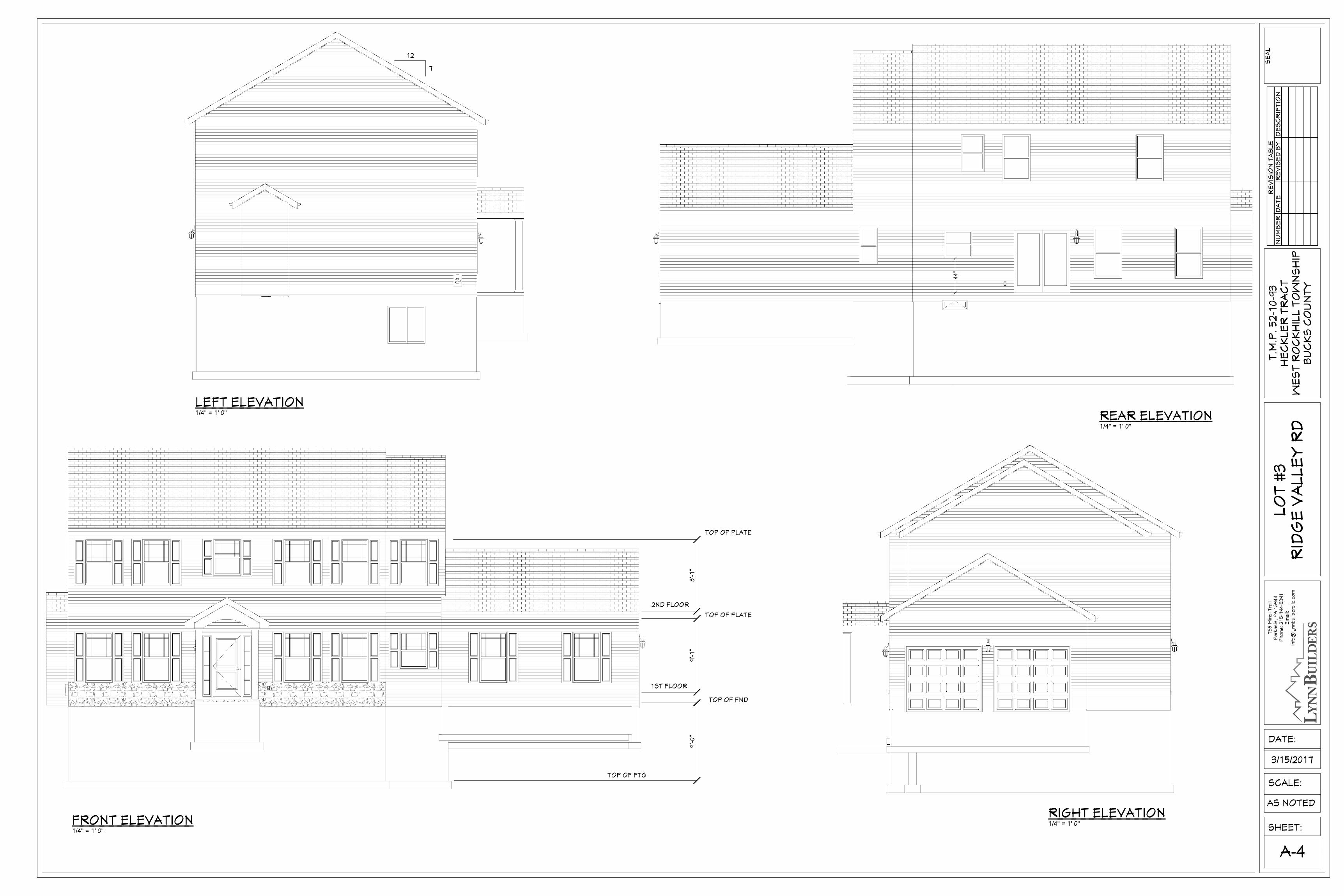
1/4" = 1' 0"
1/4" = 1' 0"
LO
T #
3R
IDG
E V
AL
LE
Y R
D
3/15/2017
1/4" = 1' 0"
7
12
1/4" = 1' 0"
TOP OF FTG
TOP OF FND
1ST FLOOR
2ND FLOOR
TOP OF PLATE
TOP OF PLATE
9'-0
"9
'-1
"8
'-1
"
LEFT ELEVATION
RIGHT ELEVATION
REAR ELEVATION
FRONT ELEVATION
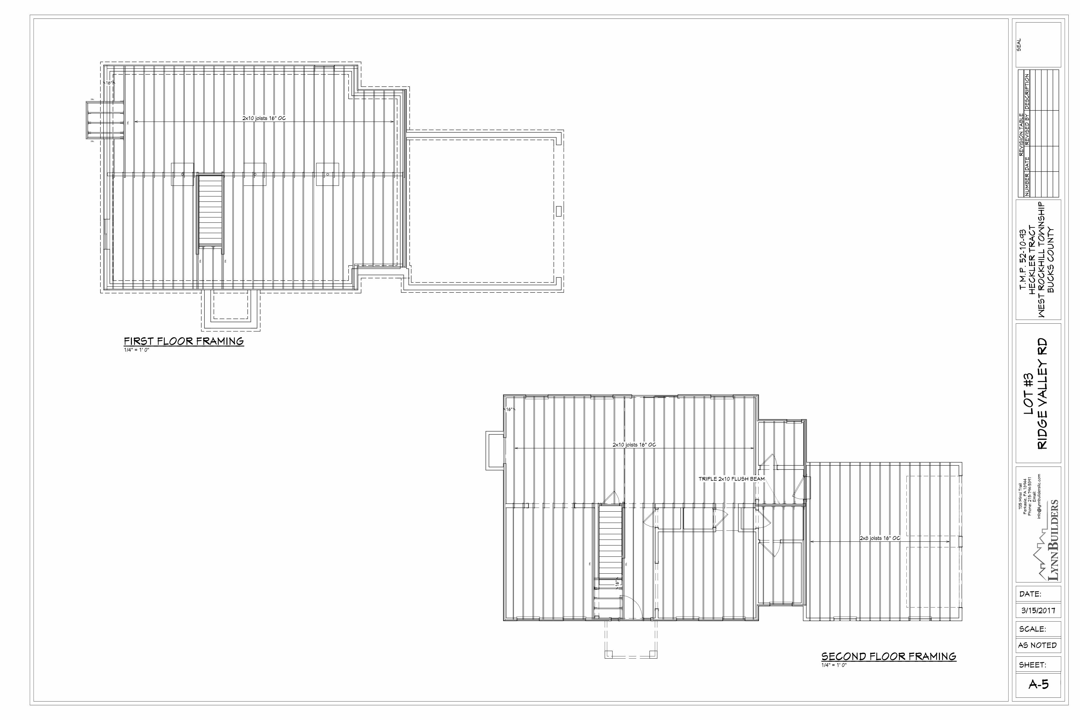
16"
16"
2x8 joists 16" OC
2x10 joists 16" OC
DB
L
TRIPLE 2x10 FLUSH BEAM
DB
L
16"
2x10 joists 16" OC
DB
L
DB
L
DBL
DBL
DB
L
RE
VIS
ION
TA
BL
EN
UM
BE
RD
AT
ER
EV
ISE
D B
YD
ES
CR
IPT
ION
SHEET:
SCALE:
T.M
.P.
52
-10
-93
HE
CK
LE
R T
RA
CT
WE
ST
RO
CK
HIL
L T
OW
NS
HIP
BU
CK
S C
OU
NT
Y
73
5 M
insi T
rail
Pe
rka
sie
, P
A 1
89
44
Ph
on
e: 2
15
-79
4-5
39
1E
ma
il:in
fo@
lyn
nb
uild
ers
llc.c
om
DATE:
AS NOTED
SE
AL
LO
T #
3R
IDG
E V
AL
LE
Y R
D
3/15/2017
1/4" = 1' 0"
FIRST FLOOR FRAMING
1/4" = 1' 0"
SECOND FLOOR FRAMING
A-5
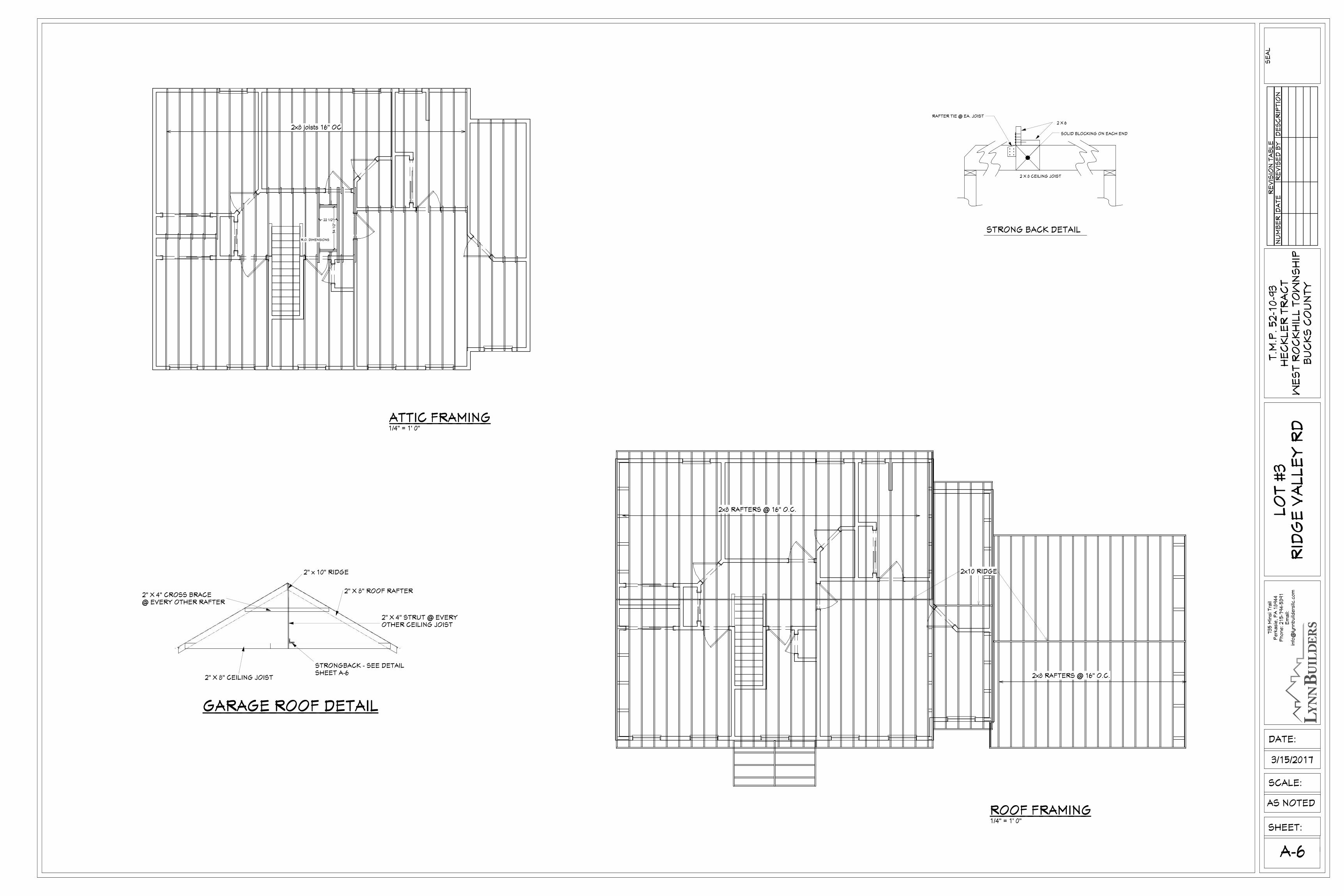
2x8 RAFTERS @ 16" O.C.
2x8 RAFTERS @ 16" O.C.
2x10 RIDGE
54 1
/2"
22 1/2"
2x8 joists 16" OC
R.O. DIMENSIONS
2 X 8 CEILING JOIST
STRONG BACK DETAIL
2 X 6
SOLID BLOCKING ON EACH END
RAFTER TIE @ EA. JOIST
RE
VIS
ION
TA
BL
EN
UM
BE
RD
AT
ER
EV
ISE
D B
YD
ES
CR
IPT
ION
SHEET:
SCALE:
T.M
.P.
52
-10
-93
HE
CK
LE
R T
RA
CT
WE
ST
RO
CK
HIL
L T
OW
NS
HIP
BU
CK
S C
OU
NT
Y
A-6
73
5 M
insi T
rail
Pe
rka
sie
, P
A 1
89
44
Ph
on
e: 2
15
-79
4-5
39
1E
ma
il:in
fo@
lyn
nb
uild
ers
llc.c
om
DATE:
AS NOTED
SE
AL
LO
T #
3R
IDG
E V
AL
LE
Y R
D
3/15/2017
1/4" = 1' 0"
ROOF FRAMING
1/4" = 1' 0"
ATTIC FRAMING
GARAGE ROOF DETAIL
2" x 10" RIDGE
2" X 4" CROSS BRACE@ EVERY OTHER RAFTER
2" X 8" ROOF RAFTER
2" X 4" STRUT @ EVERYOTHER CEILING JOIST
2" X 8" CEILING JOIST
STRONGBACK - SEE DETAILSHEET A-6
5.
9.
10.
8.
7.
6.
4.
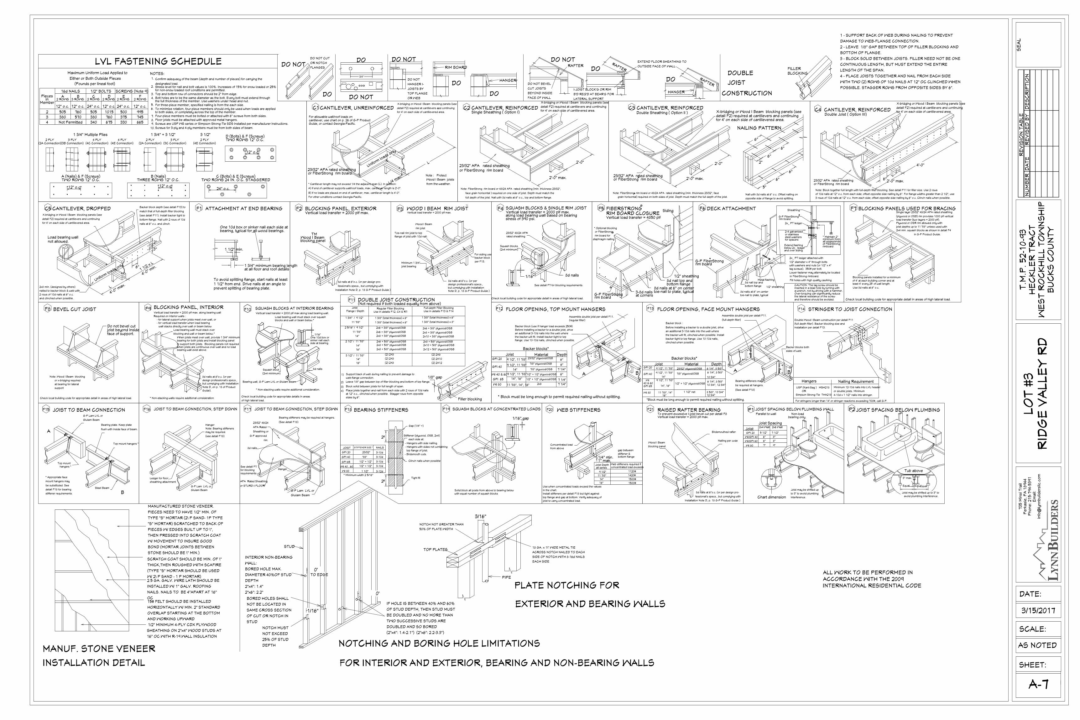
15# FELT SHOULD BE INSTALLED
HORIZONTALLY W/ MIN. 2" STANDARD
OVERLAP STARTING AT THE BOTTOM
AND WORKING UPWARD
MANUFACTURED STONE VENEER.
PIECES NEED TO HAVE 1/2" MIN. OF
TYPE "S" MORTAR (2\ P SAND- 1P TYPE
"S" MORTAR) SCRATCHED TO BACK OF
PIECES W/ EDGES BUILT UP TO \",
THEN PRESSED INTO SCRATCH COAT
W/ MOVEMENT TO INSURE GOOD
BOND (MORTAR JOINTS BETWEEN
STONE SHOULD BE \" MIN.)
SCRATCH COAT SHOULD BE MIN. OF \"
THICK,THEN ROUGHED WITH SCAFIRE
(TYPE "S" MORTAR SHOULD BE USED
W/ 2\ P SAND - 1 P MORTAR)2.5 GA. GALV. WIRE LATH SHOULD BE
INSTALLED W/ 1" GALV. ROOFING
NAILS. NAILS TO BE 4"APART AT 16"
OC
1/2" MINIMUM 4-PLY CDX PLYWOOD
SHEATHING ON 2"x4" WOOD STUDS AT
16" OC WITH R-19 WALL INSULATION
MANUF. STONE VENEER
INSTALLATION DETAIL
TM
for 4' on each side of cantilevered area.
detail F2) required at cantilevers and continuing
X-bridging or Wood I Beam blocking panels (see
L
L/4 max.*
Wood I Beam joists
Note : Protect
from the weather.
C1
For allowable wall/roof loads on
CANTILEVER, UNREINFORCED
cantilever, use chart on p. 26 of G-P ProductGuide, or contact Georgia-Pacific.
Uniform
loads only
or FiberStrong rim board.23/32" APA rated sheathing
B) If no loads are placed on end of cantilever, max. cantilever length is 4'-0".
For other conditions contact Georgia-Pacific.
A) If end of cantilever supports wall/roof loads, max. cantilever length is 2'-0".
* Cantilever length may not exceed 1/4 the adjacent span (L). In addition:
full depth of the joist. Nail with 8d nails at 6" o.c., top and bottom flange.
face grain horizontal ) required on one side of joist. Depth must match the
Note: FiberStrong rim board or 48/24 APA rated sheathing (min. thickness 23/32",
or FiberStrong rim board23/32" APA rated sheathing
Single Sheathing ( Option I)CANTILEVER, REINFORCED C2
2'-0" max.
2'-0"
X-bridging or Wood I Beam blocking panels (see
detail F2) required at cantilevers and continuingfor 4' on each side of cantilevered area.
joist to carry concentrated load.
top flange and gap at bottom. Verify adequacy of
Use when concentrated loads exceed the values
Install stiffeners per detail F18 but tight against
in the chart.
from above
Concentrated load
WEB STIFFENERSF20
concentrated load exceedsWeb stiffeners required if
1500#
1500#
1420#
1120#
all series
16"
14"
11 7/8"
9 1/2"
1" max.1/4" min. bottom flange
stiffener &
gap between
Joist Depth
WOOD I BEAM RIM JOIST
joist bearing
Minimum 1 3/4"
flange of joist with 10d nail:
Toe-nail rim joist to top
Vertical load transfer = 2000 plf max.F3
Wood I Beam
rim joist
TM
Note D, p. 18 G-P Product Guide.)
design professional's specs.,but complying with installation
8d nails at 6"o.c. (or per
For siding use backer block
per F13.
(2) 2X8(2) 2X83 1/2" / 11 7/8"
at 12" o.c., clinched when possible. Stagger rows from opposite
Block solid between joists for full length of span.
Leave 1/8" gap between top of filler blocking and bottom of top flange.
Place joists together and nail from each side with 2 rows of 10d nails
Support back of web during nailing to prevent damage to
4)
sides by 6".
3)
2)
1)web-flange connection.
16"
14"
(2) 2X8
(2) 2X8
(2) 2X12
(2) 2X10
2x8 + 3/8" plywood/OSB
1 3/8" (total thickness) x 6"
Use in details F12, C4 & R7Regular Filler Blocking
1 3/8" (total thickness) x 6"
2x8 + 5/8" plywood/OSB
2x8 + 5/8" plywood/OSB
2x6 + 5/8" plywood/OSB
2x6 + 3/8" plywood/OSB
2x6 + 3/8" plywood/OSB
11 7/8"
2 1/2" / 11 7/8"
2 5/16" / 9 1/2"
14"
16"
11 7/8"
14"
Flange / Depth
1 3/4" / 9 1/2"
Joist
1 3/8" (total thickness) x 8"
2x10 + 3/8" plywood/OSB
2x10 + 5/8" plywood/OSB
2x12 + 5/8" plywood/OSB
2x8 + 5/8" plywood/OSB
2x8 + 3/8" plywood/OSB
2x6 + 3/8" plywood/OSB
1 3/8" (total thickness) x 6"
Use in details F13 & F14Full-depth Filler Blocking
1/8" gap
12"
(Not required if both loaded equally from above)DOUBLE JOIST CONSTRUCTION
Filler blocking
F11
23/32"
* Minimum width 2 5/16"
WI 40 , 60
GPI 65
GPI 40
WI 80 1 1/2"
1/2" + 1/2"
1/2" + 1/2"
7/8"
2"
3-12d
3-10d
3-10d
3-10d
BEARING STIFFENERS
STIFFENER SIZE *JOIST
GPI 20
F18
2"
3-10d
NAILS
- Birdsmouth cuts.
Clinch nails when possible
Tight fit
Stiffener (plywood, OSB, 2x4)
- Hangers with side nailing.
- Hangers with sides not containing
top flange of joist.
each side at:
Gap (1/4" +)
Check local building code for appropriate detail in areas of high lateral load.
support
at bearing for lateral
or x-bridging required
Note: Wood I Beam blocking
BEVEL CUT JOISTF8
joist beyond insideface of support.
Do not bevel cut
* Non-stacking walls require additional consideration.
Load bearing wall must stack over
Vertical load transfer = 2000 plf max. along bearing wall
BLOCKING PANEL, INTERIOR
blocking and wall or beam below.*
8d nails at 6"o.c. (or per
Note D, on p. 18 of Product
but complying with Installationdesign professional's specs.,
Guide).
- for lateral support when joists meet over wall, or - for vertical load transfer when load bearing
wall stacks directly over wall or beam below
Required on interior walls :
F9
bearing wall exist above.
When joists meet over wall, provide 1 3/4" minimumbearing for both joists and install blocking panel
to support both joists. Blocking panels not requiredwhen joists are continuous over wall and no load
Load bearing wall must stack over squash
* Non-stacking walls require additional consideration.
blocks and wall or beam below.*
Vertical load transfer = 2000 plf max along load bearing wall.
SQUASH BLOCKS AT INTERIOR BEARING
of high lateral load.
Check local building code for appropriate details in areas
Bearing wall, G-P Lam LVL or Glulam Beam
(2x4 minimum)
Squash block
F10
8d nails
1/16"
side at bearing.sinker nail eachOne 10d box or
G-P Lam LVL or
Glulam Beam
JOIST TO BEAM CONNECTION
stiffener requirements.
detail F18 for bearing
be substituted. See
mount hangers may
* Appropriate face
hangers *Top mount
A
F15
Steel Beam
B
flush with inside face of beam.
Bearing plate. Keep plate
Top mount hangers *
JOIST TO BEAM CONNECTION, STEP DOWN
APA Rated Sheathing
or STURD-I-FLOOR
requirements.for blockingSee detail F7
Hanger
G-P approved
Sheathing or
APA Rated
23/32" 48/24
8d nails.
rim.
F17
Glulam Beam
G-P Lam LVL or
Bearing stiffeners may be required at hangers.
(See detail F18)
JOIST TO BEAM CONNECTION, STEP DOWN
sheathing attachment
Ledger for floor
F16
G-P Lam LVL or
Glulam Beam
Note: Bearing stiffeners
(see detail F18)
may be required.
Hanger
4'-0" m
ax.2x8 min. (designed by others)
nailed to backer block & web with
2 rows of 10d nails at 6" o.c.
and clinched when possible.
L
Uniform
loads only
Load bearing wallnot allowed.
X-bridging or Wood I Beam blocking panels (see
detail F2) required at cantilevers and continuing
for 4' on each side of cantilevered area.
CANTILEVER, DROPPEDC5
6"1 1/2 x L
4'-0" m
in.
Backer block depth (see detail F13) to
match that of full-depth filler blocking
(see detail F11). Install backer tight to
bottom flange. Nail with 2 rows of 10d
3"
2"
nails at 6" o.c. and clinch.
NOTES:
1 3/4" + 3 1/2"
Screws for 3-ply and 4-ply members must be from both sides of beam.
Screws are USP WS series or Simpson Strong-Tie SDS installed per manufacturer instructions.
B (Nails)THREE ROWS 12" O.C.
LVL FASTENING SCHEDULE
Confirm adequacy of the beam (depth and number of pieces) for carrying the
designated load.Stress level for nail and bolt values is 100%. Increases of 15% for snow loaded or 25%for non-snow loaded roof conditions are permitted.Top and bottom row of connectors should be 2" from edge.Bolt holes are to be the same diameter as the bolt. Every bolt must extend throughthe full thickness of the member. Use washers under head and nut.For three-piece member, specified nailing is from the each side.To minimize rotation, four-piece members should only be used when loads are appliedto both sides, or completely across the top of the member.Four-piece members must be bolted or attached with 6" screws from both sides.Floor joists must be attached with approved metal hangers.
1 3/4" Multiple Plies
TWO ROWS 12" O.C.A (Nails) & F (Screws)
12" o.c.
2 PLY(2A Connection)(3B Connection)
3 PLY 4 PLY(4E Connection)(4C Connection)
4 PLY 2 PLY(2A Connection)
Either or Both Outside Pieces
Maximum Uniform Load Applied to
(Pounds per lineal foot)
Pieces
Member2 ROWS
12" o.c.
505
380
Not Permitted4
3
2
570
3 ROWS
12" o.c.
760
16d NAILS
inA B
SCREWS (Note 9)
2 ROWS
24" o.c.
500
375
330
380
340
2 ROWS
24" o.c.
505
675
760
2 ROWS
12" o.c.
1015
1/2" BOLTS
C D
665
745
995
2 ROWS
12" o.c.
FE3.
2.
1.
TWO ROWS 12" O.C.D (Bolts) & F (Screws)
C (Bolts) & E (Screws)TWO ROWS 24 IN. O.C. STAGGERED
12" o.c.24" o.c.
(4E Connection)3 PLY
(3C Connection)2 PLY
3 1/2"
12" o.c.
bearing, typical for all wood bearings.
1 1/2" from end. Drive nails at an angle to To avoid splitting flange, start nails at least
One 10d box or sinker nail each side at
ATTACHMENT AT END BEARING
prevent splitting of bearing plate.
F1
1 1/2" min.
at all floor and roof details1 3/4" minimum bearing length
BLOCKING PANEL, EXTERIOR
blocking panel
Vertical load transfer = 2000 plf max.
Wood I Beam
F2
TM
fessional's specs., but complying with
Installation Note D, p. 18 G-P Product Guide.)
8d nails at 6"o.c. (or per design pro-
3 rows of 10d nails at 12" o.c. from each side; offset opposite side nailing by 6" o.c. Clinch nails when possible.
of 10d nails at 12" o.c. from each side; offset opposite side nailing by 6". For flange widths greater than 2 1/2", use
Note: Block together full length with full-depth filler blocking. See detail F11 for filler size. Use 2 rows
or FiberStrong rim board23/32" APA rated sheathing 6"
Double Joist ( Option III)CANTILEVER, REINFORCED C4
2'-0" max.
4'-0"
X-bridging or Wood I Beam blocking panels (see
detail F2) required at cantilevers and continuingfor 4' on each side of cantilevered area.
Check local building code for appropriate detail in areas of high lateral load.
BLOCKING PANELS USED FOR BRACING
Use 8d nails at 6" o.c.
least 4' every 25' of wall length.of 4' at each building corner and atBlocking panels installed for a minimum
F7
(plywood or OSB) rim provides 1000 plf vertical
2x4 min. squash blocks as shown in detail F4
joist depths up to 11 7/8" unless used with
Plywood or OSR rim allowed only withload transfer (two layers = 2000 plf).
in G-P Product Guide.
Single layer 23/32" 48/24 APA rated sheathing
JOIST SPACING BELOW PLUMBINGP2
Tub above
avoid plumbing interference.
Joist may be shifted up to 3" to
Equal
3" max.
Equal
(regular filler)
Assemble double joist per detail F11.
Depth Material Joist
9 1/2", 11 7/8"
9 1/2", 11 7/8"
9 1/2", 11 7/8"
11 7/8", 14", 16"
* Block must be long enough to permit required nailing without splitting.
WI 40 & 60
WI 80
GPI 65 14", 16"
GPI 40
GPI 20
14"
1/2" + 1/2" plywood/OSB
1/2" + 1/2" plywood/OSB
2x8
7/8" plywood/OSB
7/8" plywood/OSB
23/32" plywood/OSB
6"
7 1/4"
7 1/4"
6"
7 1/4"
6"
FLOOR OPENING, TOP MOUNT HANGERSF12
Backer block (use if hanger load exceeds 250#)
the backer will fit. Install backer tight to top
Before installing a backer to a double joist, drive
flange. Use 10-10d nails, clinched when possible.
an additional 3-10d nails into the web where
Backer blocks*
A B
(full-depth filler)
Assemble double joist per detail F11.
1/2" + 1/2" plywood/OSB
*Block must be long enough to permit required nailing without splitting.
14", 16"GPI 65
WI 8016"
11 7/8", 14"
GPI 40
GPI 20
40 & 60
9 1/2", 11 7/8"
14"
9 1/2", 11 7/8"
9 1/2", 11 7/8"WI
Joist
10 3/4", 12 3/4"
12 3/4"8 5/8", 10 3/4"1 1/2" net
10 3/4"
6 1/4", 8 5/8"
6 1/4", 8 5/8"
6 1/4", 8 5/8"
23/32" plywood/OSB
7/8" plywood/OSB
Material
Backer blocks*
Depth
FLOOR OPENING, FACE MOUNT HANGERSF13
the backer will fit, clinched when possible. Install
Before installing a backer to a double joist, drive
backer tight to top flange. Use 10-10d nails,
an additional 3-10d nails into the web where
clinched when possible.
Backer block :
sides of web.
(See detail F18)
be required at hangers.
Bearing stiffeners may
A B
Backer blocks both
Minimum 12-10d nails into LVL header
Nailing Requirement
STRINGER TO JOIST CONNECTION
For stringers longer than 14' or stringer reactions exceeding 700#, call G-P.
Simpson Strong-Tie THA218
USP (Kant-Sag ) MSH218
Hangers
OR
4-10d x 1 1/2" nails into stringer.
or double joists. Minimum
Double Wood I Beam construction per detail F11
(full depth filler). Backer blocking size and
installation per detail F13.
F14
To prevent excessive I-joist bevel cut per detail F8
Wood I Beam
blocking panel
RAISED RAFTER BEARING
Vertical load transfer = 2000 plf max.
F21
Nailing per code
8d nails at 6"o.c. (or per design pro-
Installation Note D, p. 18 G-P Product Guide.)
fessional's specs., but complying with
Birdsmouthed rafter
SQUASH BLOCKS AT CONCENTRATED LOADS
Solid block all posts from above to bearing belowwith equal number of squash blocks
F19
1/16" gap
Chart dimension
Joist Spacing
Parallel to wall
JOIST SPACING BELOW PLUMBING WALL
WI/GPI 60
WI 80 7"
GPI 20
WI/GPI 40
Joist 5 1/2"
6"
6"
2x4 Wall
P1
interference.
to 3" to avoid plumbing
Joist may be shifted up
9"
7 1/2"
8"
8"
2x6 Wall
bearing only.Non-load
grain horizontal) required on both sides of joist. Depth must match the full depth of the joist.
Note: FiberStrong rim board or 48/24 APA rated sheathing (min. thickness 23/32", face R
or FiberStrong rim board23/32" APA rated sheathing
R 2'-0" max.
CANTILEVER, REINFORCED C3Double Sheathing ( Option ll )
Nail with 8d nails at 6" o.c. Offset nailing on
opposite side of flange to avoid splitting.
5"
2'-0" 2"
6"
6"
6"
for 4' on each side of cantilevered area.
6"
NAILING PATTERN
X-bridging or Wood I Beam blocking panels (seedetail F2) required at cantilevers and continuing
6"
3-8d nailsat corners
rim board G-P FiberStrong
R
RIM BOARD CLOSUREVertical load transfer = 4850 plf
FIBERSTRONG
diaphragm nailing
rim board for
or FiberStrong
* Optional blocking
R
F5R
bottom flange8d nail top and
toe-nail to plate, typical8d nails at 6" on center
1/2" sheathing
Siding
Check local building code for appropriate detail in areas of high lateral load.
See detail F7 for blocking requirements.
SQUASH BLOCKS & SINGLE RIM JOIST
(2x4 minimum)
1/16"
F4
rated sheathing
23/32" 48/24 APA
Squash blocks
R
along load bearing wall based on bearing Vertical load transfer = 2000 plf max.
stress of 390 psi.
8d nails
8d nail top and
toe-nail to plate, typical
8d nails at 6" on center
rim board G-P FiberStrong
bottom flange
R
DECK ATTACHMENTF6
and over siding
Fill holes with high quality caulking.
in FiberStrong rimboard.
and therefore should be avoided.the lateral resistance of the screwOver-torquing can significantly reducea wrench, not by driving with a hammer.inserted in a lead hole by turning withCAUTION: The lag screw should be
lag screws). 350# per bolt.with washers and nuts (or 1/2" x 4"1/2" diameter x 4" through bolts
2x_ PT ledger attached with
Lower fastener may alternately be located
1/2" sheathing
flashingMetal
2" (min.)
Extend flashingbelow 2x_ ledger
steel washersfor spacers
2-4 galvanizedor stainless
2x_ PT ledger
rim boardG-P FiberStrong
Sheathing
R
* Maintain 2"
rimboardof FiberStrongall edges/ends minimum from
NOTCH NOT GREATER THAN
50% OF PLATE WIDTH
TOP PLATES
PIPE
PLATE NOTCHING FOR
EXTERIOR AND BEARING WALLS
18 GA. x 1\" WIDE METAL TIE
ACROSS NOTCH NAILED TO EACH
SIDE OF NOTCH WITH 8-16d NAILS
EACH SIDE
STUD
TO EDGE
INTERIOR NON-BEARING
WALL:
BORED HOLE MAX.
DIAMETER 40%OF STUD
DEPTH
2"x4": 1.4"
2"x6": 2.2"
NOTCH MUST
NOT EXCEED
25% OF STUD
DEPTH
BORED HOLES SHALL
NOT BE LOCATED IN
SAME CROSS SECTION
OF CUT OR NOTCH IN
STUD
IF HOLE IS BETWEEN 40% AND 60%
OF STUD DEPTH, THEN STUD MUST
BE DOUBLED AND NO MORE THAN
TWO SUCCESSIVE STUDS ARE
DOUBLED AND SO BORED
(2"x4": 1.4-2.1") (2"x6": 2.2-3.3")
NOTCHING AND BORING HOLE LIMITATIONS
FOR INTERIOR AND EXTERIOR, BEARING AND NON-BEARING WALLS
1 - SUPPORT BACK OF WEB DURING NAILING TO PREVENT
DAMAGE TO WEB-FLANGE CONNECTION.
2 - LEAVE 1/8" GAP BETWEEN TOP OF FILLER BLOCKING AND
BOTTOM OF FLANGE.
3 - BLOCK SOLID BETWEEN JOISTS. FILLER NEED NOT BE ONE
CONTINUOUS LENGTH, BUT MUST EXTEND THE ENTIRE
LENGTH OF THE SPAN.
4 - PLACE JOISTS TOGETHER AND NAIL FROM EACH SIDE
WITH TWO (2) ROWS OF 10d NAILS AT 12" OC CLINCHED WHEN
POSSIBLE. STAGGER ROWS FROM OPPOSITE SIDES BY 6".
DO NOT
DO
DO
DO
DODO NOT
DO NOT
DOUBLE
JOIST
CONSTRUCTION
DO
DO
DO NOT
DO NOT BEVEL
CUT JOISTS
BEYOND INSIDE
FACE OF WALL
RAFTER
I-JOIST BLOCK'G OR RIM
B'D REQ'D AT BEAR'G FOR
LATERAL SUPPORT
EXTEND FLOOR SHEATHING TO
OUTSIDE FACE OF WALL
RAFTER
RAFTER
HANGER
FILLERBLOCKING
DO NOT
HANGER I-
JOISTS BY
TOP FLANGE
OR WEB
RIM BOARD
HANGER
DO NOT CUT
OR NOTCH
FLANGES
ALL WORK TO BE PERFORMED INACCORDANCE WITH THE 2009INTERNATIONAL RESIDENTIAL CODE
3/16"
1/16"
0'
0'
3/4"
0'
RE
VIS
ION
TA
BL
EN
UM
BE
RD
AT
ER
EV
ISE
D B
YD
ES
CR
IPT
ION
SHEET:
SCALE:
T.M
.P.
52
-10
-93
HE
CK
LE
R T
RA
CT
WE
ST
RO
CK
HIL
L T
OW
NS
HIP
BU
CK
S C
OU
NT
Y
A-7
73
5 M
insi T
rail
Pe
rka
sie
, P
A 1
89
44
Ph
on
e: 2
15
-79
4-5
39
1E
ma
il:in
fo@
lyn
nb
uild
ers
llc.c
om
DATE:
AS NOTED
SE
AL
LO
T #
3R
IDG
E V
AL
LE
Y R
D
3/15/2017
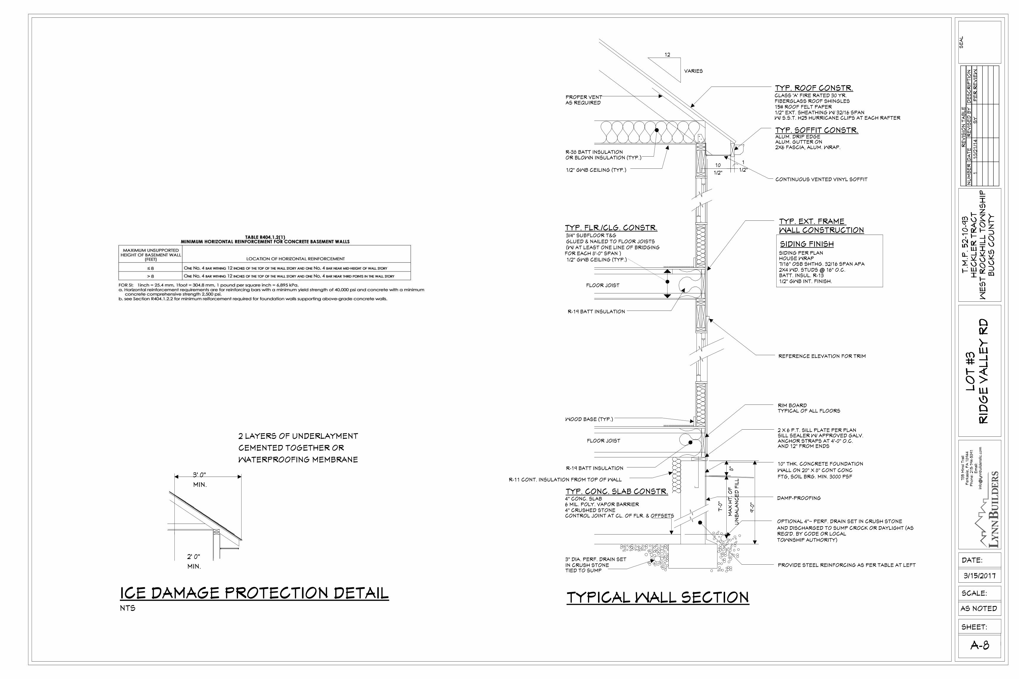
10" THK. CONCRETE FOUNDATION
IN CRUSH STONETIED TO SUMP
3" DIA. PERF. DRAIN SET
4" CRUSHED STONE6 MIL. POLY. VAPOR BARRIER
TYP. CONC. SLAB CONSTR.4" CONC. SLAB
CONTROL JOINT AT CL. OF FLR. & OFFSETS
TOWNSHIP AUTHORITY)REQ'D. BY CODE OR LOCALAND DISCHARGED TO SUMP CROCK OR DAYLIGHT (AS
OPTIONAL 4''~ PERF. DRAIN SET IN CRUSH STONE
DAMP-PROOFING
WALL ON 20" X 8" CONT CONCFTG, SOIL BRG. MIN. 3000 PSF
UN
BA
LA
NC
ED
FIL
L
MA
X H
T.
OF
VARIES
WOOD BASE (TYP.)
GLUED & NAILED TO FLOOR JOISTS
1/2" GWB CEILING (TYP.)
R-19 BATT INSULATION
FOR EACH 8'-0" SPAN )(W/ AT LEAST ONE LINE OF BRIDGING
FLOOR JOIST
1/2" GWB CEILING (TYP.)
3/4" SUBFLOOR T&G
TYP. FLR./CLG. CONSTR.
AS REQUIREDPROPER VENT
OR BLOWN INSULATION (TYP.)R-38 BATT INSULATION
12
ANCHOR STRAPS AT 4'-0" O.C.
2 X 6 P.T. SILL PLATE PER PLANSILL SEALER W/ APPROVED GALV.
REFERENCE ELEVATION FOR TRIM
AND 12" FROM ENDS
TYP. EXT. FRAME WALL CONSTRUCTION
SIDING FINISH
HOUSE WRAP7/16" OSB SHTHG. 32/16 SPAN APA2X4 WD. STUDS @ 16" O.C.BATT. INSUL. R-131/2" GWB INT. FINISH.
ALUM. GUTTER ON2X6 FASCIA, ALUM. WRAP.
TYP. ROOF CONSTR.
TYP. SOFFIT CONSTR.ALUM. DRIP EDGE
CLASS 'A' FIRE RATED 30 YR.FIBERGLASS ROOF SHINGLES15# ROOF FELT PAPER1/2'' EXT. SHEATHING W/ 32/16 SPAN
FLOOR JOIST
R-19 BATT INSULATION
CONTINUOUS VENTED VINYL SOFFIT
10
1/2"
1
1/2"
9'-0
''
7'-0
''
8''
TYPICAL WALL SECTION
W/ S.S.T. H25 HURRICANE CLIPS AT EACH RAFTER
TYPICAL OF ALL FLOORSRIM BOARD
SIDING PER PLAN
R-11 CONT. INSULATION FROM TOP OF WALL
PROVIDE STEEL REINFORCING AS PER TABLE AT LEFT
RE
VIS
ION
TA
BL
EN
UM
BE
RD
AT
ER
EV
ISE
D B
YD
ES
CR
IPT
ION
SHEET:
SCALE:
T.M
.P.
52
-10
-93
HE
CK
LE
R T
RA
CT
WE
ST
RO
CK
HIL
L T
OW
NS
HIP
BU
CK
S C
OU
NT
Y
A-8
73
5 M
insi T
rail
Pe
rka
sie
, P
A 1
89
44
Ph
on
e: 2
15
-79
4-5
39
1E
ma
il:in
fo@
lyn
nb
uild
ers
llc.c
om
DATE:
AS NOTED
SE
AL
LO
T #
3R
IDG
E V
AL
LE
Y R
D
3/15/2017
2' 0"
MIN.
2 LAYERS OF UNDERLAYMENT
CEMENTED TOGETHER OR
WATERPROOFING MEMBRANE
ICE DAMAGE PROTECTION DETAILNTS
11
0/2
1/1
4S
YP
ER
RE
VIE
W
3' 0"
MIN.
ALL WORK TO BE PERFORMED INACCORDANCE WITH THE 2009INTERNATIONAL RESIDENTIAL CODE
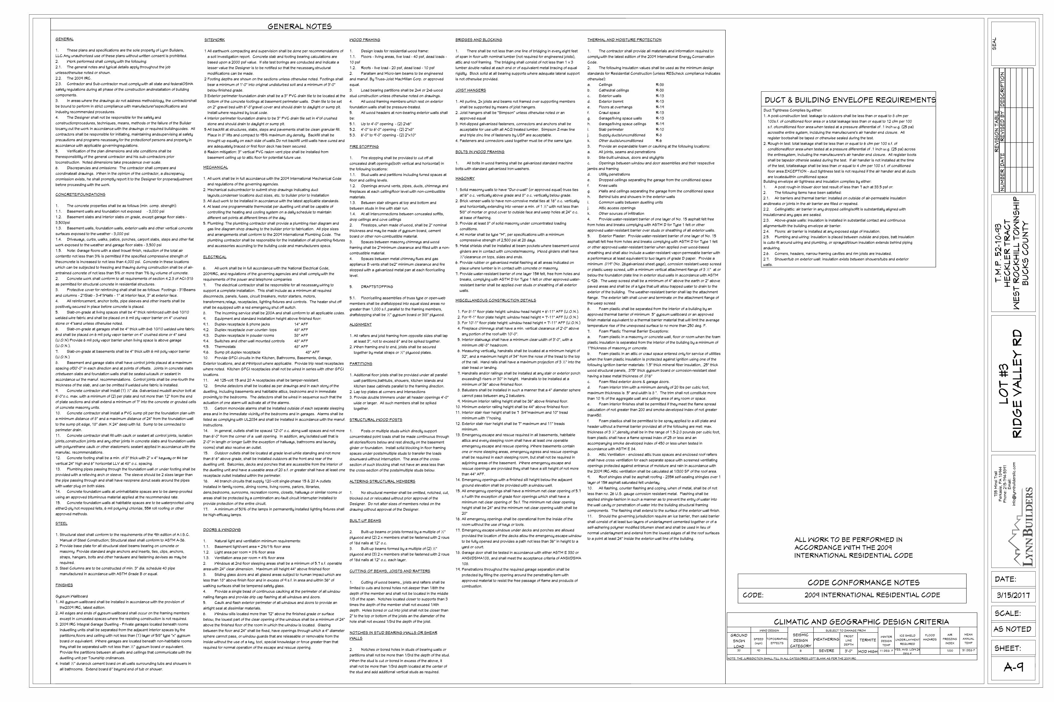
SITEWORK
1 All earthwork compacting and supervision shall be done per recommendations of
a soil investigation report. Concrete slab and footing bearing calculations are
based upon a 2000 psf value. If site test borings are conducted and indicate a
lesser value the Designer is to be notified so that the necessary structural
modifications can be made.
2 Footing depths are shown on the sections unless otherwise noted. Footings shall
bear a minimum of 1'-0" into original undisturbed soil and a minimum of 3'-0"
below finished grade.
3 Exterior perimeter foundation drain shall be a 3" PVC drain tile to be located at the
bottom of the concrete footings at basement perimeter walls. Drain tile to be set
on 2" gravel bed with 6"-8"gravel cover and should drain to daylight or sump pit.
Install where required by local code.
4 Interior perimeter foundation drains to be 3" PVC drain tile set in 4"of crushed
stone and should drain to daylight or sump pit.
5 All backfill at structures, slabs, steps and pavements shall be clean granular fill.
Place in 8" lifts and compact to 95% maximum dry density. Backfill shall be
brought up equally on each side of walls.Do not backfill until walls have cured and
are adequately braced or first floor deck has been secured.
6 Radon mitigation: 3" vertical PVC radon vent pipe shall be installed from
basement ceiling up to attic floor for potential future use.
CONCRETE/FOUNDATIONS
1. The concrete properties shall be as follows (min. comp. strength):
1.1. Basement walls and foundation not exposed - 3,000 psi
1.2. Basement slabs and interior slabs on grade, except garage floor slabs -
3,500psi
1.3. Basement walls, foundation walls, exterior walls and other vertical concrete
surfaces exposed to the weather - 3,000 psi
1.4. Driveways, curbs, walks, patios, porches, carport slabs, steps and other flat
work exposed to the weather and garage floor slabs - 3,500 psi
1.5. Note: Garage floors with a steel trowel finish, reduction of the total air
contentto not less than 3% is permitted if the specified compressive strength of
theconcrete is increased to not less than 4,000 psi. Concrete in these locations
which can be subjected to freezing and thawing during construction shall be of air-
entrained concrete of not less than 5% or more than 7% by volume of concrete.
2. Concrete work shall conform to all requirements of section 4.2.3 of ACI-318
as permitted for structural concrete in residential structures.
3. Protective cover for reinforcing shall shall be as follows: Footings - 3"/Beams
and columns - 2"/Slab - 3-4"/Walls - 1" at interior face, 3" at exterior face.
4. All reinforcement, anchor bolts, pipe sleeves and other inserts shall be
positively secured in place before concrete is placed.
5. Slab-on-grade at living spaces shall be 4" thick reinforced with 6x6 10/10
welded wire fabric and shall be placed on 6 mil ply vapor barrier on 4" crushed
stone or 4"sand unless otherwise noted.
6. Slab-on-grade at garages shall be 4" thick with 6x6 10/10 welded wire fabric
and shall be placed on 6 mil poly vapor barrier on 4" crushed stone or 4" sand
(U.O.N) Provide 6 mil poly vapor barrier when living space is above garage
(U.O.N.).
7. Slab-on-grade at basements shall be 4" thick with 6 mil poly vapor barrier
(U.O.N.)
8. Basement and garage slabs shall have control joints placed at a maximum
spacing of30'-0" in each direction and at points of offsets. Joints in concrete slabs
orbetween slabs and foundation walls shall be sealed w/caulk or sealant in
accordance w/ the manuf. recommendations. Control joints shall be one-fourth the
thickness of the slab, and can be omitted if welded wire fabric is installed.
9. Concrete contractor shall install (1) ½" dia. Galvanized mudsill anchor bolt at
6'-0"o.c. max. with a minimum of (2) per plate and not more than 12" from the end
of plate sections and shall extend a minimum of 7" into the concrete or grouted cells
of concrete masonry units.
10. Concrete contractor shall install a PVC sump pit per the foundation plan with
a minimum distance of 8" and a maximum distance of 24" from the foundation wall
to the sump pit edge, 18" diam. X 24" deep with lid. Sump to be connected to
perimeter drain.
11. Concrete contractor shall fill with caulk or sealant all control joints, isolation
joints,construction joints and any other joints in concrete slabs and foundation walls
with polyurethane caulk or other elastomeric sealant applied in accordance with the
manufac. recommendations.
12. Concrete footing shall be a min. of 8" thick with 2" x 4" keyway or #4 bar
vertical 24" high and 6" horizontal LLV at 48" o.c. spacing.
13. Plumbing pipes passing through the foundation wall or under footing shall be
provided with a relieving arch or sleeve. The sleeve should be 2 sizes larger than
the pipe passing through and shall have neoprene donut seals around the pipes
with water plug on both sides.
14. Concrete foundation walls at uninhabitable spaces are to be damp-proofed
using an approved bituminous material applied at the recommended rate.
15. Concrete foundation walls at habitable spaces are to be waterproofed using
either2-ply hot mopped felts, 6 mil polyvinyl chloride, 55# roll roofing or other
approved methods.
MASONRY
1. Solid masonry walls to have "Dur-o-wall" (or approved equal) truss ties
at16" o.c. vertically above grade and 8" o.c. vertically below grade.
2. Brick veneer walls to have non-corrosive metal ties at 16" o.c. vertically
and horizontally extending into veneer a min. of 1 ½" with not less than
5/8" of mortar or grout cover to outside face and weep holes at 24" o.c.
at base of flashing.
3. Provide at least 8" of solid masonry under concentrated loading
conditions.
4. All mortar shall be type "M", per specifications with a minimum
compressive strength of 2,500 psi at 28 days.
5. Metal shields shall be installed at beam pockets where basement wood
girders are in contact with concrete/masonry. Wood girders shall have
½"clearance on tops, sides and ends.
6. Provide rubber or galvanized metal flashing at all areas indicated on
place where lumber is in contact with concrete or masonry.
7. Provide water-resistant barrier of one layer 15# felt, free from holes and
breaks, complying with ASTM D for Type 1 felt or other approved water-
resistant barrier shall be applied over studs or sheathing of all exterior
walls.
STEEL
1. Structural steel shall conform to the requirements of the 9th edition of A.I.S.C.
Manual of Steel Construction; Structural steel shall conform to ASTM A-36.
2. Provide base plate for all structural steel beams bearing on concrete or
masonry. Provide standard angle anchors and inserts, ties, clips, anchors,
straps, hangars, bolts and other hardware and fastening devises as may be
required.
3. Steel Columns are to be constructed of min. 3" dia. schedule 40 pipe
manufactured in accordance with ASTM Grade B or equal.
FINISHES
Gypsum Wallboard
1. All gypsum wallboard shall be installed in accordance with the provision of
the2009 IRC, latest edition.
2. All edges and ends of gypsum wallboard shall occur on the framing members
except in concealed spaces where fire resisting construction is not required.
3. 2009 IRC Integral Garage Dwelling - Private garages located beneath rooms
indwelling units shall be separated from the adjacent interior spaces by fire
partitions,floors and ceiling with not less than (1) layer of 5/8" type "x" gypsum
board or equivalent. Where garages are located beneath non-habitable rooms
they shall be separated with not less than ½" gypsum board or equivalent.
Provide fire partitions between all walls and ceilings that communicate with the
dwelling unit per Township ordinances.
4. Install ½" durarock cement board on all walls surrounding tubs and showers in
all bathrooms. Extend board 6" beyond end of tub or shower.
MECHANICAL
1. All work shall be in full accordance with the 2009 International Mechanical Code
and regulations of the governing agencies.
2. Mechanical subcontractor to submit shop drawings indicating duct
layouts,condenser locations duct sizes, etc. to builder prior to installation
3. All duct work to be installed in accordance with the latest applicable standards.
4. At least one programmable thermostat per dwelling unit shall be capable of
controlling the heating and cooling system on a daily schedule to maintain
different set points at different times of the day.
5. Plumbing: The plumbing contractor shall provide a plumbing riser diagram and
gas line diagram shop drawing to the builder prior to fabrication. All pipe sizes
and arrangements shall conform to the 2009 International Plumbing Code. The
plumbing contractor shall be responsible for the installation of all plumbing fixtures
and accessories according to the building code and manufacturers specs.
ELECTRICAL
6. All work shall be in full accordance with the National Electrical Code,
2009IRC, and regulations of the governing agencies and shall comply with the
requirements of the power and telephone companies
7. The electrical contractor shall be responsible for all necessary wiring to
support a complete installation. This shall include as a minimum all required
disconnects, panels, fuses, circuit breakers, motor starters, motors,
transformers,relays, receptacles, lighting fixtures and controls. The heater shut off
shall be equipped with a red emergency shut off switch.
8. The incoming service shall be 200A and shall conform to all applicable codes.
9. Equipment and standard installation height above finished floor:
9.1. Duplex receptacle & phone jacks 14" AFF
9.2. Duplex receptacle over counter- tops 48" AFF
9.3. Duplex receptacle in powder rooms 38" AFF
9.4. Switches and other wall mounted controls 48" AFF
9.5. Thermostats 48" AFF
9.6. Sump pit duplex receptacle 48" AFF
10. Provide GFCI circuits in the Kitchen, Bathrooms, Basements, Garage,
Exterior locations, and at Whirlpool where applicable. Provide trip reset receptacles
where noted. Kitchen GFCI receptacles shall not be wired in series with other GFCI
locations.
11. All 125-volt 15 and 20 A receptacles shall be tamper-resistant.
12. Smoke detectors shall be located as per drawings and in each story of the
dwelling, including basements and habitable attics, bedrooms and in immediate
proximity to the bedrooms. The detectors shall be wired in sequence such that the
actuation of one alarm will activate all of the alarms.
13. Carbon monoxide alarms shall be installed outside of each separate sleeping
area and in the immediate vicinity of the bedrooms and in garages. Alarms shall be
listed as complying with UL2034 and shall be installed in accordance with the manuf.
instructions.
14. In general, outlets shall be spaced 12'-0" o.c. along wall spaces and not more
than 6'-0" from the corner of a wall opening. In addition, any isolated wall that is
2'-0" in length or longer (with the exception of hallways, bathrooms and laundry
rooms) shall also receive an outlet.
15. Outdoor outlets shall be located at grade level while standing and not more
than 6'-6" above grade, shall be installed outdoors at the front and rear of the
dwelling unit. Balconies, decks and porches that are accessible from the interior of
the dwelling unit and have a useable area of 20 s.f. or greater shall have at least one
receptacle outlet installed within the perimeter.
16. All branch circuits that supply 120-volt single-phase 15 & 20 A outlets
installed in family rooms, dining rooms, living rooms, parlors, libraries,
dens,bedrooms, sunrooms, recreation rooms, closets, hallways or similar rooms or
areas shall be protected by a combination arc-fault circuit interrupter installed to
provide protection of the entire circuit.
17. A minimum of 50% of the lamps in permanently installed lighting fixtures shall
be high-efficacy lamps.
THERMAL AND MOISTURE PROTECTION
1. The contractor shall provide all materials and information required to
comply with the latest edition of the 2009 International Energy Conservation
Code.
2. The following insulation values shall be used as the minimum design
standards for Residential Construction (unless REScheck compliance indicates
otherwise):
a. Ceilings R-38
b. Cathedral ceilings R-38
c. Exterior walls R-13
d. Exterior bsmnt R-13
e. Floors at overhangs R-19
f. Crawl space R-13
g. Garage/living space walls R-13
h. Garage/living space ceilings R-19
i. Slab perimeter R-10
j. Supply ducts/unconditioned R-8
k. Other ducts/unconditioned R-6
3. Provide an expandable foam or caulking at the following locations:
a. All joints, seams and penetrations
b. Site-built windows, doors and skylights
c. Openings between window and door assemblies and their respective
jambs and framing
d. Utility penetrations
e. Dropped ceilings separating the garage from the conditioned space
f. Knee walls
g. Walls and ceilings separating the garage from the conditioned space
h. Behind tubs and showers in the exterior walls
i. Common walls between dwelling units
j. Attic access openings
k. Other sources of infiltration
4. Provide water-resistant barrier of one layer of No. 15 asphalt felt free
from holes and breaks complying with ASTM D for Type 1 felt or other
approved water-resistant barrier over studs or sheathing of all exterior walls.
5. Exterior Plaster: Provide water-resistant barrier of one layer of No. 15
asphalt felt free from holes and breaks complying with ASTM D for Type 1 felt
or other approved water-resistant barrier when applied over wood-based
sheathing and shall also include a water-resistant vapor-permeable barrier with
a performance at least equivalent to two layers of grade D paper. Provide a
minimum .019" (No. 26galvanized sheet gage), corrosion resistant weep screed
or plastic weep screed, with a minimum vertical attachment flange of 3 ½" at or
below the foundation plate line in exterior stud walls in accordance with ASTM
C 926. The weep screed shall be a minimum of 4" above the earth or 2" above
paved areas and shall be of a type that will allow trapped water to drain to the
exterior of the building. The weather-resistant barrier shall lap the attachment
flange. The exterior lath shall cover and terminate on the attachment flange of
the weep screed
6. Foam plastic shall be separated from the interior of a building by an
approved thermal barrier of minimum .5" gypsum wallboard or an approved
finish material equivalent to a thermal barrier material that will limit the average
temperature rise of the unexposed surface to no more than 250 deg. F.
7. Foam Plastic Thermal Barrier Exceptions:
a. Foam plastic in a masonry or concrete wall, floor or room when the foam
plastic insulation is separated from the interior of the building by a minimum of
1"thickness of masonry or concrete.
b. Foam plastic in an attic or crawl space entered only for service of utilities
when the foam plastic insulation is protected against ignition using one of the
following ignition barrier materials: 1.5" thick mineral fiber insulation, .25" thick
wood structural panels, .375" thick gypsum board or corrosion-resistant steel
having a base metal thickness of .016"
c. Foam filled exterior doors & garage doors.
d. Foam interior trim with a minimum density of 20 lbs per cubic foot,
maximum thickness is .5" and width is 8 ". The trim shall not constitute more
than 10 % of the aggregate wall and ceiling area of any room or space.
e. Foam interior finishes shall be permitted if they meet the flame spread
calculation of not greater than 200 and smoke-developed index of not greater
than450.
f. Foam plastics shall be permitted to be spray applied to a sill plate and
header without a thermal barrier provided all of the following are met: max.
thickness of 3 ¼",density shall be in the range of 1.5-2.0 pounds per cubic foot,
foam plastic shall have a flame spread index of 25 or less and an
accompanying smoke developed index of 450 or less when tested in
accordance with ASTM E 84.
8. Attic Ventilation - enclosed attic truss spaces and enclosed roof rafters
shall have cross ventilation for each separate space with screened ventilating
openings protected against entrance of moisture and rain in accordance with
the 2009 IRC.Attic ventilation shall be calculated at 1/300 SF of the roof area.
9. Roof shingles shall be asphalt roofing - 235# self-sealing shingles over 1
layer of 15# asphalt saturated felt underlay.
10. All flashing, counter flashing and coping, when of metal, shall be of not
less than no. 26 U.S. gauge corrosion resistant metal. Flashing shall be
applied shingle-fashion in such a manner as to prevent the entry of water into
the wall cavity or penetration of water into the building structural framing
components. The flashing shall extend to the surface of the exterior wall finish.
11. Should the governing jurisdiction require an ice barrier, then said barrier
shall consist of at least two layers of underlayment cemented together or of a
self-adhering polymer modified bitumen sheet and shall be used in lieu of
normal underlayment and extend from the lowest edges of all the roof surfaces
to a point at least 24" inside the exterior wall line of the building.
DOORS & WINDOWS
1. Natural light and ventilation minimum requirements:
1.1. Basement light/vent area = 2%/1% floor area
1.2. Light area per room = 8% floor area
1.3. Ventilation area per room = 4% floor area
2. Windows at 2nd floor sleeping areas shall be a minimum of 5.7 s.f. operable
area with 24" clear dimension. Maximum sill height 44" above finished floor
3. Sliding glass doors and all glazed areas subject to human impact which are
less than 18" above finish floor and in excess of 9 s.f. in area and within 36" of
walking surfaces shall be tempered safety glass.
4. Provide a single bead of continuous caulking at the perimeter of all window
nailing flanges and provide drip cap flashing at all windows and doors.
5. Caulk and flash exterior perimeter of all windows and doors to provide an
airtight seal at dissimilar materials.
6. Window sills located more than 72" above the finished grade or surface
below, the lowest part of the clear opening of the windows shall be a minimum of 24"
above the finished floor of the room in which the window is located. Glazing
between the floor and 24" shall be fixed, have openings through which a 4" diameter
sphere cannot pass, or window guards that are releasable or removable from the
inside without the use of a key, tool, special knowledge or force greater than that
required for normal operation of the escape and rescue opening.
WOOD FRAMING
1. Design loads for residential wood frame:
1.1. Floors - living areas, live load - 40 psf, dead loads -
10 psf
1.2. Roofs - live load - 20 psf, dead load - 10 psf
2. Parallam and Micro-lam beams to be engineered
and manuf. By Truss-Joist MacMillan Corp. or approved
equal.
3. Load bearing partitions shall be 2x4 or 2x6 wood
stud construction unless otherwise noted on drawings.
4. All wood framing members which rest on exterior
foundation walls shall be pressure-treated.
5. All wood headers at non-bearing exterior walls shall
be:
5.1. Up to 4'-0" opening - (2) 2'x6"
5.2. 4'-0" to 6'-0" opening - (2) 2"x8"
5.3. 6'-0" to 9'-0" opening - (2) 2"x10"
FIRE STOPPING
1. Fire stopping shall be provided to cut off all
concealed draft openings(both vertical and horizontal) in
the following locations:
1.1. Stud walls and partitions including furred spaces at
floor and ceiling levels.
1.2. Openings around vents, pipes, ducts, chimneys and
fireplaces at each ceiling/floor level with non-combustible
materials.
1.3. Between stair stingers at top and bottom and
between studs in line with stair run.
1.4. At all interconnections between concealed soffits,
drop ceilings and cove ceilings
2. Firestops, when made of wood, shall be 2" nominal
thickness and may be made of gypsum board, cement
board or other non-combustible material.
3. Spaces between masonry chimneys and wood
framing shall be 2"minimum clearance and filled with a non-
combustible material.
4. Spaces between metal chimney flues and gas
appliance B vents shall be2" minimum clearance and fire
stopped with a galvanized metal pan at each floor/ceiling
level.
5. DRAFTSTOPPING
5.1. Floor/ceiling assemblies of truss type or open-web
members shall be draftstopped into equal sized areas no
greater than 1,000 s.f.,parallel to the framing members,
draftstopping shall be ½" gypsum board or 3/8" plywood.
ALIGNMENT
1. All rafters and joist framing from opposite sides shall lap
at least 3", not to exceed 6" and be spiked together.
2. When framing end to end, joists shall be secured
together by metal straps or ½" plywood plates.
PARTITIONS
1. Additional floor joists shall be provided under all parallel
wall partitions,bathtubs, showers, kitchen islands and
kitchen base cabinets parallel to the framing direction.
2. Lap top plates at corners and intersections
3. Provide double trimmers under all header openings 4'-0"
wide or larger. All such members shall be spiked
together.
STRUCTURAL WOOD POSTS
1. Posts or multiple studs which directly support
concentrated point loads shall be made continuous through
all stories/floors below and rest directly on the basement
girder or foundation. Install solid blocking in floor framing
spaces under posts/multiple studs to transfer the loads
downward without interruption. The area of the cross-
section of such blocking shall not have an area less than
the cross-section of the posts/multiple studs below.
ALTERING STRUCTURAL MEMBERS
1. No structural member shall be omitted, notched, cut,
blocked out or relocated without prior approval of the
Designer. Do not alter sizes of members noted on the
drawing without approval of the Designer.
BUILT-UP BEAMS
2. Built-up beams or joists formed by a multiple of ½"
plywood and (2) 2 x members shall be fastened with 2 rows
of 16d nails at 12" o.c.
3. Built-up beams formed by a multiple of (2) ½"
plywood and (3) 2 x members shall be fastened with 2 rows
of 16d nails at 12" o.c. each layer.
CUTTING OF BEAMS, JOISTS AND RAFTERS
1. Cutting of wood beams,, joists and rafters shall be
limited to cuts and bored holes not deeper than 1/6th the
depth of the member and shall not be located in the middle
1/3 of the span. Notches located closer to supports than 3
times the depth of the member shall not exceed 1/4th
depth. Holes bored or cut into joist shall not be closer than
2" to the top or bottom of the joists an the diameter of the
hole shall not exceed 1/3rd the depth of the joist.
NOTCHES IN STUD BEARING WALLS OR SHEAR
WALLS
2. Notches or bored holes in studs of bearing walls or
partitions shall not be more than 1/3rd the depth of the stud.
When the stud is cut or bored in excess of the above, it
shall not be more than 1/3rd depth located at the center of
the stud and add additional vertical studs as required.
BRIDGES AND BLOCKING
1. There shall be not less than one line of bridging in every eight feet
of span in floor with nominal lumber (not required for engineered joists),
attic and roof framing. The bridging shall consist of not less than 1 x 3
lumber double nailed at each end or of equivalent metal bracing of equal
rigidity. Block solid at all bearing supports where adequate lateral support
is not otherwise provided.
JOIST HANGERS
1. All purlins, 2x joists and beams not framed over supporting members
shall be supported by means of joist hangers.
2. Joist hangers shall be "Simpson" unless otherwise noted or an
approved equal
3. Hot-dipped galvanized fasteners, connectors and anchors shall be
acceptable for use with all ACQ treated lumber. Simpson Z-max line
and triple zinc line of fasteners by USP are acceptable.
4. Fasteners and connectors used together must be of the same type.
BOLTS IN WOOD FRAMING
1. All bolts in wood framing shall be galvanized standard machine
bolts with standard galvanized iron washers.
MISCELLANEOUS CONSTRUCTION DETAILS
1. For 8'-1" floor plate height: window head height = 6'-11" AFF (U.O.N.).
2. For 9'-1" floor plate height: window head height = 7'-11" AFF (U.O.N.)
3. For 10'-1" floor plate height: window head height = 7'-11" AFF (U.O.N.)
4. Fireplace chimneys shall have a min. vertical clearance of 2'-0" above
any portion of the roof with 10'-0".
5. Interior stairways shall have a minimum clear width of 3'-0", with a
minimum of6'-8" headroom.
6. Measuring vertically, handrails shall be located at a minimum height of
32", and a maximum height of 34" from the nose of the tread to the top
of the rail. Hand rails shall have a maximum projection of 3 ½" into the
stair tread or landing.
7. Handrails and/or railings shall be installed at any stair or exterior porch
exceeding3 risers or 30" in height. Handrails to be installed at a
minimum of 36" above finished floor.
8. Balusters shall be installed in such a manner that a 4" diameter sphere
cannot pass between any 2 balusters.
9. Minimum interior railing height shall be 36" above finished floor.
10. Minimum exterior railing height shall be 44" above finished floor.
11. Interior stair riser height shall be 7 3/4"maximum and 10" tread
minimum with 1"nosing.
12. Exterior stair riser height shall be 7" maximum and 11" treads
minimum.
13. Emergency escape and rescue required in all basements, habitable
attics and every sleeping room shall have at least one operable
emergency escape and rescue opening. Where basements contain
one or more sleeping areas, emergency egress and rescue openings
shall be required in each sleeping room, but shall not be required in
adjoining areas of the basement. Where emergency escape and
rescue openings are provided they shall have a sill height of not more
than 44" AFF.
14. Emergency openings with a finished sill height below the adjacent
ground elevation shall be provided with a window well.
15. All emergency openings shall have a minimum net clear opening of 5.7
s.f with the exception of grade floor openings which shall have a
minimum net clear opening of 5s.f. The minimum net clear opening
height shall be 24" and the minimum net clear opening width shall be
20"
16. All emergency openings shall be operational from the inside of the
room without the use of keys or tools.
17. Emergency escape windows under decks and porches are allowed
provided the location of the decks allow the emergency escape window
to be fully opened and provides a path not less than 36" in height to a
yard or court.
18. Garage door shall be tested in accordance with either ASTM E 330 or
ANSI/DSMA108, and shall meet the acceptance criteria of ANSI/DSMA
108.
19. Penetrations throughout the required garage separation shall be
protected by filling the opening around the penetrating item with
approved material to resist the free passage of flame and products of
combustion.
Duct Tightness Complies by either:
1. A post-construction test: leakage to outdoors shall be less than or equal to 8 cfm per
100s.f. of conditioned floor area or a total leakage less than or equal to 12 cfm per 100
s.f. ofconditioned floor area when tested at a pressure differential of .1 inch w.g. (25 pa)
acrossthe entire system, inclduing the manufacruere's air handler end closure. All
register bootsshall be taped or otherwise sealed during the test.
2. Rough-in test: total leakage shall be less than or equal to 6 cfm per 100 s.f. of
conditionedfloor area when tested at a pressure differential of .1 inch w.g. (25 pa) across
the entiresystem, including the manufacurere's air handler end closure. All register boots
shall be tapedor othersie sealed during the test. If air handler is not installed at the time
of the test, totalleakage shall be less than or equal to 4 cfm per 100 s.f. of conditioned
floor area.EXCEPTION - duct tightness test is not required if the air handler and all ducts
are locatedwithin conditioned spaceBuilding envelope air tightness and insulation complies by either:
1. A post rough-in blower door test result of less than 7 ach at 33.5 psf or:
2. The following items have been satisfied:
2.1. Air barriers and thermal barrier: installed on outside of air-permeable insulation
andbreaks or joints in the air barrier are filled or repaired.
2.2. Ceiling/attic: air barrier in any dropped ceiling/soffit is substantially aligned with
insulationand any gaps are sealed.
2.3. Above-grade walls: insulation is installed in substantial contact and continuous
alignmentwith the building envelope air barrier.
2.4. Floors: air barrier is installed at any exposed edge of insulation.
2.5. Plumbing and wiring: insulation is placed between outside and pipes, batt insulation
is cutto fit around wiring and plumbing, or sprayed/blown insulation extends behind piping
andwiring.
2.6. Corners, headers, narrow framing cavities and rim joists are insulated.
2.7. Shower/tub on exterior wall: insulation exists between showers/tubs and exterior
walls.
DUCT & BUILDING ENVELOPE REQUIREMENTS
CODE CONFORMANCE NOTES
CODE: 2009 INTERNATIONAL RESIDENTIAL CODE
CLIMATIC AND GEOGRAPHIC DESIGN CRITERIA
NOTE: THE JURISDICTION SHALL FILL IN ALL CATEGORIES LEFT BLANK AS PER THE 2009 IRC
GROUND
SNOW
LOAD30
WIND DESIGN
SEISMIC
DESIGN
CATEGORY
TOPOGRAPHIC
EFFECTS
SPEED
(mph)
90 B
SUBJECT TO DAMAGE FROM
WEATHERINGFROST
LINE
DEPTH
TERMITE
SEVERE 3'-0" MOD HIGH
WINTER
DESIGN
TEMP
ICE SHIELD
UNDER-LAYMENT
REQUIRED
FLOOD
HAZARDS
AIR
FREEZING
INDEX
MEAN
ANNUAL
TEMP
11 DEG. F YES, AVG. LOW 24
DEG F1000 51 DEG F
GENERAL NOTES
GENERAL
1. These plans and specifications are the sole property of Lynn Builders,
LLC.Any unauthorized use of these plans without written consent is prohibited.
2. Work performed shall comply with the following:
2.1. The general notes and typical details apply throughout the job
unlessotherwise noted or shown.
2.2. The 2009 IRC.
2.3. Contractor and Sub-contractor must comply with all state and federalOSHA
safety regulations during all phase of the construction andinstallation of building
components.
3. In areas where the drawings do not address methodology, the contractorshall
be bound to perform in strict compliance with manufacturer'sspecifications and
industry recommended procedures.
4. The Designer shall not be responsible for the safety and
constructionprocedures, techniques, means, methods or the failure of the Builder
tocarry out the work in accordance with the drawings or required buildingcodes. All
contractors shall be responsible for initiating, maintaining andsupervising al safety
precautions and programs necessary for the protectionof persons and property in
accordance with applicable governingregulations.
5. Verification of the plan dimensions and site conditions shall be
theresponsibility of the general contractor and his sub-contractors prior
toconstruction. Noted dimensions take precedence over scale.
6. Discrepancies and omissions: The contractor shall compare and
coordinateall drawings. When in the opinion of the contractor, a discrepancy
oromission exists, he shall promptly report it to the Designer for properadjustment
before proceeding with the work.
RE
VIS
ION
TA
BL
EN
UM
BE
RD
AT
ER
EV
ISE
D B
YD
ES
CR
IPT
ION
SHEET:
SCALE:
T.M
.P.
52
-10
-93
HE
CK
LE
R T
RA
CT
WE
ST
RO
CK
HIL
L T
OW
NS
HIP
BU
CK
S C
OU
NT
Y
A-9
73
5 M
insi T
rail
Pe
rka
sie
, P
A 1
89
44
Ph
on
e: 2
15
-79
4-5
39
1E
ma
il:in
fo@
lyn
nb
uild
ers
llc.c
om
DATE:
AS NOTED
SE
AL
LO
T #
3R
IDG
E V
AL
LE
Y R
D
3/15/2017
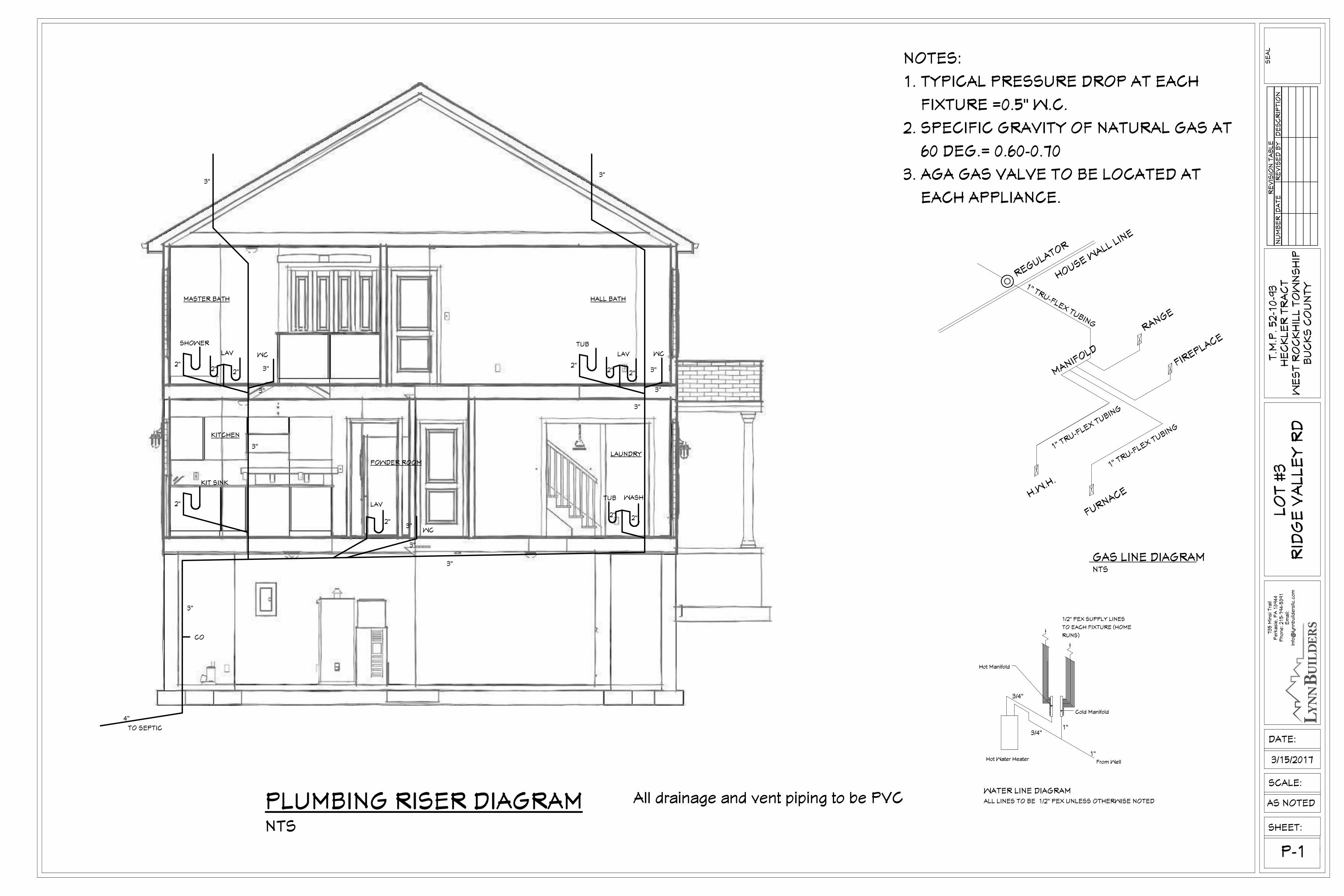
Hot Water Heater
WATER LINE DIAGRAMALL LINES TO BE 1/2" PEX UNLESS OTHERWISE NOTED
1"
1"3/4"
3/4"
Cold Manifold
Hot Manifold
1/2" PEX SUPPLY LINES
TO EACH FIXTURE (HOME
RUNS)
From Well
RANGE
H.W.H.
REGULATOR
1" TRU-FLEX TUBING
HOUSE WALL LINE
FURNACE
1" TRU-FLEX TUBING
1" TRU-FLEX TUBING
MANIFOLD
FIREPLACE
GAS LINE DIAGRAMNTS
RE
VIS
ION
TA
BL
EN
UM
BE
RD
AT
ER
EV
ISE
D B
YD
ES
CR
IPT
ION
SHEET:
SCALE:
T.M
.P.
52
-10
-93
HE
CK
LE
R T
RA
CT
WE
ST
RO
CK
HIL
L T
OW
NS
HIP
BU
CK
S C
OU
NT
Y
P-1
73
5 M
insi T
rail
Pe
rka
sie
, P
A 1
89
44
Ph
on
e: 2
15
-79
4-5
39
1E
ma
il:in
fo@
lyn
nb
uild
ers
llc.c
om
DATE:
AS NOTED
SE
AL
LO
T #
3R
IDG
E V
AL
LE
Y R
D
3/15/2017
NOTES:
1. TYPICAL PRESSURE DROP AT EACH
FIXTURE =0.5" W.C.
2. SPECIFIC GRAVITY OF NATURAL GAS AT
60 DEG.= 0.60-0.70
3. AGA GAS VALVE TO BE LOCATED AT
EACH APPLIANCE.
All drainage and vent piping to be PVCPLUMBING RISER DIAGRAMNTS
MASTER BATH HALL BATH
KITCHEN
POWDER ROOM
LAUNDRY
WC
SHOWER
LAV
3"2"
2" 2"
3"
3"
3"
TUB
LAV
2"2" 2"
WC
3"
3"
3"3"
WC3"
3"
LAV
2"
TUB
2" 2"
WASH2"
KIT SINK
3"
3"
CO
4"
TO SEPTIC
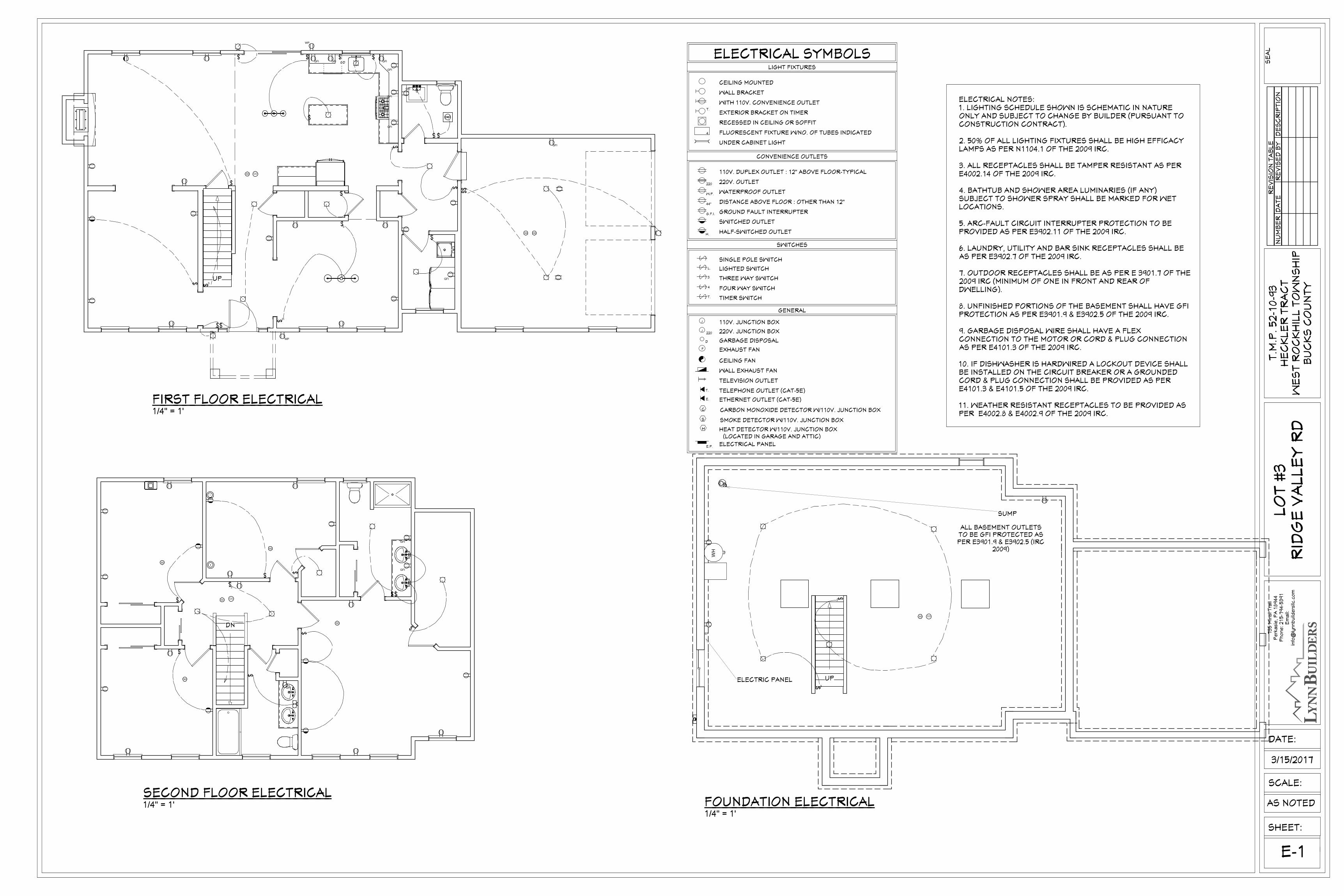
WH
UP
SD CO
3
3
EP
ALL BASEMENT OUTLETSTO BE GFI PROTECTED ASPER E3901.9 & E3902.5 (IRC
2009)
ELECTRIC PANEL
SUMP
DN
COSD
SD
SD
SD
SD
GFI
GFI
GFI
3
DN
UP
SD CO
SD HD
GFIGFI GFI
WP
GFI
3
GFI
GFI
3
GFI
GFI
3
GFI
3
3
WP
GD
RE
VIS
ION
TA
BL
EN
UM
BE
RD
AT
ER
EV
ISE
D B
YD
ES
CR
IPT
ION
SHEET:
SCALE:
T.M
.P.
52
-10
-93
HE
CK
LE
R T
RA
CT
WE
ST
RO
CK
HIL
L T
OW
NS
HIP
BU
CK
S C
OU
NT
Y
E-1
73
5 M
insi T
rail
Pe
rka
sie
, P
A 1
89
44
Ph
on
e: 2
15
-79
4-5
39
1E
ma
il:in
fo@
lyn
nb
uild
ers
llc.c
om
DATE:
AS NOTED
SE
AL
LO
T #
3R
IDG
E V
AL
LE
Y R
D
3/15/2017
FIRST FLOOR ELECTRICAL
SMOKE DETECTOR W/110V. JUNCTION BOX
D
S
J
J
TELEPHONE OUTLET (CAT-5E)
ELECTRICAL PANELE.P.
TELEVISION OUTLET
WALL EXHAUST FAN
GARBAGE DISPOSAL
220V. JUNCTION BOX
110V. JUNCTION BOX
FOUR WAY SWITCH
THREE WAY SWITCH
CEILING FAN
220
3
GENERAL
DISTANCE ABOVE FLOOR : OTHER THAN 12"
110V. DUPLEX OUTLET : 12" ABOVE FLOOR-TYPICAL
ELECTRICAL SYMBOLS
CONVENIENCE OUTLETS
FLUORESCENT FIXTURE W/NO. OF TUBES INDICATED
RECESSED IN CEILING OR SOFFIT
EXTERIOR BRACKET ON TIMER
WITH 110V. CONVENIENCE OUTLET
LIGHTED SWITCH
GROUND FAULT INTERRUPTER
WATERPROOF OUTLET
220V. OUTLET
SWITCHED OUTLET
G.F.I.
44"
W.P.
220
SWITCHES
UNDER CABINET LIGHT
WALL BRACKET
CEILING MOUNTED
4
T.
LIGHT FIXTURES
HEAT DETECTOR W/110V. JUNCTION BOXH
(LOCATED IN GARAGE AND ATTIC)
EXHAUST FANF
4
TIMER SWITCHT.
HALF-SWITCHED OUTLETH.
ETHERNET OUTLET (CAT-5E)
T.
E.
SINGLE POLE SWITCH
L.
CARBON MONOXIDE DETECTOR W/110V. JUNCTION BOXC
ELECTRICAL NOTES:1. LIGHTING SCHEDULE SHOWN IS SCHEMATIC IN NATUREONLY AND SUBJECT TO CHANGE BY BUILDER (PURSUANT TOCONSTRUCTION CONTRACT).
2. 50% OF ALL LIGHTING FIXTURES SHALL BE HIGH EFFICACYLAMPS AS PER N1104.1 OF THE 2009 IRC.
3. ALL RECEPTACLES SHALL BE TAMPER RESISTANT AS PERE4002.14 OF THE 2009 IRC.
4. BATHTUB AND SHOWER AREA LUMINARIES (IF ANY)SUBJECT TO SHOWER SPRAY SHALL BE MARKED FOR WETLOCATIONS.
5. ARC-FAULT CIRCUIT INTERRUPTER PROTECTION TO BEPROVIDED AS PER E3902.11 OF THE 2009 IRC.
6. LAUNDRY, UTILITY AND BAR SINK RECEPTACLES SHALL BEAS PER E3902.7 OF THE 2009 IRC.
7. OUTDOOR RECEPTACLES SHALL BE AS PER E 3901.7 OF THE2009 IRC (MINIMUM OF ONE IN FRONT AND REAR OFDWELLING).
8. UNFINISHED PORTIONS OF THE BASEMENT SHALL HAVE GFIPROTECTION AS PER E3901.9 & E3902.5 OF THE 2009 IRC.
9. GARBAGE DISPOSAL WIRE SHALL HAVE A FLEXCONNECTION TO THE MOTOR OR CORD & PLUG CONNECTIONAS PER E4101.3 OF THE 2009 IRC.
10. IF DISHWASHER IS HARDWIRED A LOCKOUT DEVICE SHALLBE INSTALLED ON THE CIRCUIT BREAKER OR A GROUNDEDCORD & PLUG CONNECTION SHALL BE PROVIDED AS PERE4101.3 & E4101.5 OF THE 2009 IRC.
11. WEATHER RESISTANT RECEPTACLES TO BE PROVIDED ASPER E4002.8 & E4002.9 OF THE 2009 IRC.
SECOND FLOOR ELECTRICALFOUNDATION ELECTRICAL
1/4" = 1'
1/4" = 1'1/4" = 1'
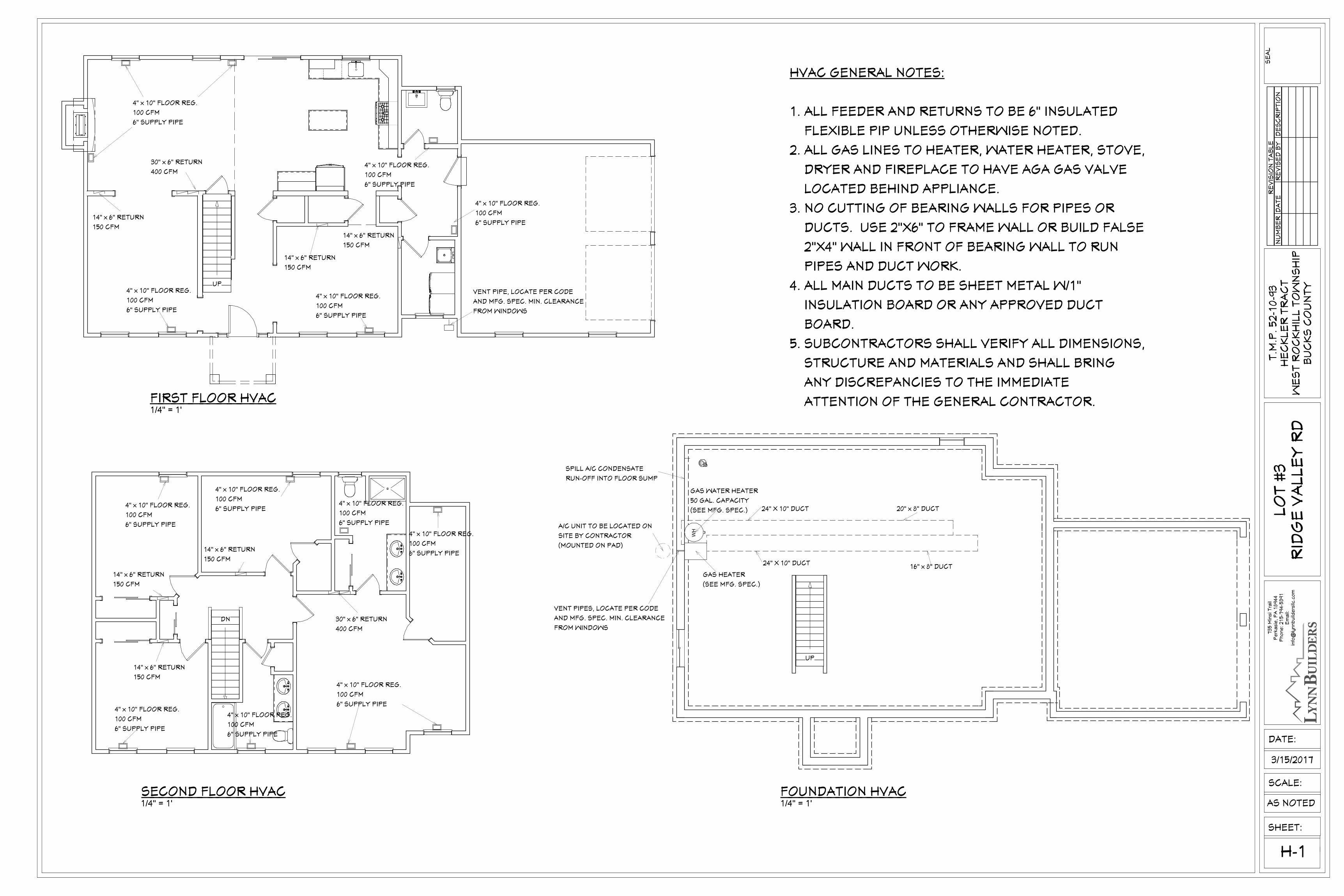
WH
UP
GAS HEATER
(SEE MFG. SPEC.)
16" x 8" DUCT
20" x 8" DUCT
24" X 10" DUCT
24" X 10" DUCT
GAS WATER HEATER
50 GAL. CAPACITY
(SEE MFG. SPEC.)
A/C UNIT TO BE LOCATED ON
SITE BY CONTRACTOR
(MOUNTED ON PAD)
VENT PIPES, LOCATE PER CODE
AND MFG. SPEC. MIN. CLEARANCE
FROM WINDOWS
SPILL A/C CONDENSATE
RUN-OFF INTO FLOOR SUMP
DN
UP
14" x 6" RETURN
150 CFM
14" x 6" RETURN
150 CFM
30" x 6" RETURN
400 CFM
14" x 6" RETURN
150 CFM
4" x 10" FLOOR REG.
100 CFM
6" SUPPLY PIPE
4" x 10" FLOOR REG.
100 CFM
6" SUPPLY PIPE
4" x 10" FLOOR REG.
100 CFM
6" SUPPLY PIPE
4" x 10" FLOOR REG.
100 CFM
6" SUPPLY PIPE
4" x 10" FLOOR REG.
100 CFM
6" SUPPLY PIPE
VENT PIPE, LOCATE PER CODE
AND MFG. SPEC. MIN. CLEARANCE
FROM WINDOWS
DN 30" x 6" RETURN
400 CFM
14" x 6" RETURN
150 CFM
14" x 6" RETURN
150 CFM
14" x 6" RETURN
150 CFM
4" x 10" FLOOR REG.
100 CFM
6" SUPPLY PIPE
4" x 10" FLOOR REG.
100 CFM
6" SUPPLY PIPE
4" x 10" FLOOR REG.
100 CFM
6" SUPPLY PIPE
4" x 10" FLOOR REG.
100 CFM
6" SUPPLY PIPE4" x 10" FLOOR REG.
100 CFM
6" SUPPLY PIPE
4" x 10" FLOOR REG.
100 CFM
6" SUPPLY PIPE
4" x 10" FLOOR REG.
100 CFM
6" SUPPLY PIPE
RE
VIS
ION
TA
BL
EN
UM
BE
RD
AT
ER
EV
ISE
D B
YD
ES
CR
IPT
ION
SHEET:
SCALE:
T.M
.P.
52
-10
-93
HE
CK
LE
R T
RA
CT
WE
ST
RO
CK
HIL
L T
OW
NS
HIP
BU
CK
S C
OU
NT
Y
H-1
73
5 M
insi T
rail
Pe
rka
sie
, P
A 1
89
44
Ph
on
e: 2
15
-79
4-5
39
1E
ma
il:in
fo@
lyn
nb
uild
ers
llc.c
om
DATE:
AS NOTED
SE
AL
LO
T #
3R
IDG
E V
AL
LE
Y R
D
3/15/2017
HVAC GENERAL NOTES:
1. ALL FEEDER AND RETURNS TO BE 6" INSULATED
FLEXIBLE PIP UNLESS OTHERWISE NOTED.
2. ALL GAS LINES TO HEATER, WATER HEATER, STOVE,
DRYER AND FIREPLACE TO HAVE AGA GAS VALVE
LOCATED BEHIND APPLIANCE.
3. NO CUTTING OF BEARING WALLS FOR PIPES OR
DUCTS. USE 2"X6" TO FRAME WALL OR BUILD FALSE
2"X4" WALL IN FRONT OF BEARING WALL TO RUN
PIPES AND DUCT WORK.
4. ALL MAIN DUCTS TO BE SHEET METAL W/1"
INSULATION BOARD OR ANY APPROVED DUCT
BOARD.
5. SUBCONTRACTORS SHALL VERIFY ALL DIMENSIONS,
STRUCTURE AND MATERIALS AND SHALL BRING
ANY DISCREPANCIES TO THE IMMEDIATE
ATTENTION OF THE GENERAL CONTRACTOR.FIRST FLOOR HVAC
SECOND FLOOR HVAC FOUNDATION HVAC
1/4" = 1'
1/4" = 1' 1/4" = 1'
Related Documents