Models all rights reserved in accordance with the law. Always mention the source when reproducing our drawings and photos. 84 Levelling elements and supports 1 2 3 4 5 6 7 8 9 10 11 12 13 14 15 RH LX Levelling elements Technopolymer base, steel or stainless steel stem BASE Polyamide based (PA) technopolymer with adjusting hexagon, black colour, matte finish. STANDARD EXECUTIONS - LX: zinc-plated steel threaded stem. - LX-S: zinc-plated steel threaded stem, base with screwdriver slot. - LX-AS: zinc-plated steel threaded stem, base with NBR rubber no-slip disk, hardness 70 Shore A, supplied assembled to the base. - LX-SST: AISI 304 stainless steel threaded stem. - LX-SST-S: AISI 304 stainless steel threaded stem, base with screwdriver slot. - LX-AS-SST: AISI 304 stainless steel threaded stem, base with NBR rubber no-slip disk, hardness 70 Shore A, supplied assembled to the base. LX - LX-S Code Description Code Description D d L L1 l l1 l2 s Max. limit static load* [N] 431001 LX.25-SW13-M6x24 431001-S LX.25-SW13-M6x26-S 25 M6 35 37 24 26 11 13 1500 8 431003 LX.25-SW13-M6x34 431003-S LX.25-SW13-M6x36-S 25 M6 45 47 34 36 11 13 1500 10 431005 LX.25-SW13-M6x54 431005-S LX.25-SW13-M6x56-S 25 M6 65 67 54 56 11 13 1500 14 431007 LX.25-SW13-M6x62 431007-S LX.25-SW13-M6x64-S 25 M6 73 75 62 64 11 13 1500 16 431011 LX.25-SW13-M8x17 431011-S LX.25-SW13-M8x19-S 25 M8 28 30 17 19 11 13 2500 10 431013 LX.25-SW13-M8x22 431013-S LX.25-SW13-M8x24-S 25 M8 33 35 22 24 11 13 2500 12 431015 LX.25-SW13-M8x32 431015-S LX.25-SW13-M8x32-S 25 M8 43 45 32 32 11 13 2500 14 431017 LX.25-SW13-M8x52 431017-S LX.25-SW13-M8x54-S 25 M8 63 65 52 54 11 13 2500 18 431019 LX.25-SW13-M8x72 431019-S LX.25-SW13-M8x74-S 25 M8 83 85 72 74 11 13 2500 22 * The max static load is the value above which the load applied to the element may cause some plastic material breakage, in particular conditions of use. Obviously, a factor that takes into consideration the importance and the safety level of the specific application must be applied to this value. STAINLESS STEEL INOX RoHS PA +100° -30° SBR +70° -30° 7/2018

Welcome message from author
This document is posted to help you gain knowledge. Please leave a comment to let me know what you think about it! Share it to your friends and learn new things together.
Transcript
Models all rights reserved in accordance with the law. Always mention the source when reproducing our drawings and photos.
84
Leve
lling
ele
men
ts a
nd s
uppo
rts
1
2
3
4
5
6
7
8
9
10
11
12
13
14
15
RH
LX Levelling elementsTechnopolymer base, steel or stainless steel stem
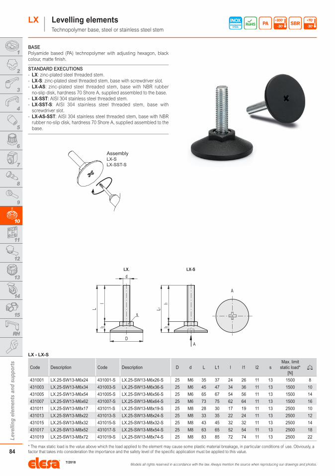
BASEPolyamide based (PA) technopolymer with adjusting hexagon, black colour, matte finish.
STANDARD EXECUTIONS - LX: zinc-plated steel threaded stem. - LX-S: zinc-plated steel threaded stem, base with screwdriver slot. - LX-AS: zinc-plated steel threaded stem, base with NBR rubber no-slip disk, hardness 70 Shore A, supplied assembled to the base.
- LX-SST: AISI 304 stainless steel threaded stem. - LX-SST-S: AISI 304 stainless steel threaded stem, base with screwdriver slot.
- LX-AS-SST: AISI 304 stainless steel threaded stem, base with NBR rubber no-slip disk, hardness 70 Shore A, supplied assembled to the base.
LX - LX-S
Code Description Code Description D d L L1 l l1 l2 sMax. limit
static load* [N]
431001 LX.25-SW13-M6x24 431001-S LX.25-SW13-M6x26-S 25 M6 35 37 24 26 11 13 1500 8
431003 LX.25-SW13-M6x34 431003-S LX.25-SW13-M6x36-S 25 M6 45 47 34 36 11 13 1500 10
431005 LX.25-SW13-M6x54 431005-S LX.25-SW13-M6x56-S 25 M6 65 67 54 56 11 13 1500 14
431007 LX.25-SW13-M6x62 431007-S LX.25-SW13-M6x64-S 25 M6 73 75 62 64 11 13 1500 16
431011 LX.25-SW13-M8x17 431011-S LX.25-SW13-M8x19-S 25 M8 28 30 17 19 11 13 2500 10
431013 LX.25-SW13-M8x22 431013-S LX.25-SW13-M8x24-S 25 M8 33 35 22 24 11 13 2500 12
431015 LX.25-SW13-M8x32 431015-S LX.25-SW13-M8x32-S 25 M8 43 45 32 32 11 13 2500 14
431017 LX.25-SW13-M8x52 431017-S LX.25-SW13-M8x54-S 25 M8 63 65 52 54 11 13 2500 18
431019 LX.25-SW13-M8x72 431019-S LX.25-SW13-M8x74-S 25 M8 83 85 72 74 11 13 2500 22
* The max static load is the value above which the load applied to the element may cause some plastic material breakage, in particular conditions of use. Obviously, a factor that takes into consideration the importance and the safety level of the specific application must be applied to this value.
STAINLESSSTEEL
INOX
RoHS PA +100°
-30° SBR +70°
-30°
LXLX
7/2018

Models all rights reserved in accordance with the law. Always mention the source when reproducing our drawings and photos.
85
Leve
lling
ele
men
ts a
nd s
uppo
rts
1
2
3
4
5
6
7
8
9
10
11
12
13
14
15
RH
2|5LX Levelling elements
LX - LX-S
Code Description Code Description D d L L1 l l1 l2 sMax. limit
static load* [N]
431051 LX.30-SW17-M6x22 431051-S LX.30-SW17-M6x24-S 30 M6 34 36 22 24 12 17 1500 14
431053 LX.30-SW17-M6x32 431053-S LX.30-SW17-M6x34-S 30 M6 44 46 32 34 12 17 1500 16
431055 LX.30-SW17-M6x52 431055-S LX.30-SW17-M6x54-S 30 M6 64 66 52 54 12 17 1500 20
431057 LX.30-SW17-M8x16 431057-S LX.30-SW17-M8x18-S 30 M8 28 30 16 18 12 17 2500 17
431059 LX.30-SW17-M8x21 431059-S LX.30-SW17-M8x23-S 30 M8 33 35 21 23 12 17 2500 18
431061 LX.30-SW17-M8x31 431061-S LX.30-SW17-M8x33-S 30 M8 43 45 31 33 12 17 2500 20
431063 LX.30-SW17-M8x51 431063-S LX.30-SW17-M8x53-S 30 M8 63 65 51 53 12 17 2500 24
431065 LX.30-SW17-M8x71 431065-S LX.30-SW17-M8x73-S 30 M8 83 85 71 73 12 17 2500 28
431067 LX.30-SW17-M10x16 431067-S LX.30-SW17-M10x18-S 30 M10 28 30 16 18 12 17 3000 21
431069 LX.30-SW17-M10x21 431069-S LX.30-SW17-M10x23-S 30 M10 33 35 21 23 12 17 3000 22
431071 LX.30-SW17-M10x31 431071-S LX.30-SW17-M10x33-S 30 M10 43 45 31 33 12 17 3000 24
431073 LX.30-SW17-M10x41 431073-S LX.30-SW17-M10x43-S 30 M10 53 55 41 43 12 17 3000 26
431075 LX.30-SW17-M10x51 431075-S LX.30-SW17-M10x53-S 30 M10 63 65 51 53 12 17 3000 28
431077 LX.30-SW17-M10x61 431077-S LX.30-SW17-M10x63-S 30 M10 73 75 61 63 12 17 3000 30
431079 LX.30-SW17-M10x71 431079-S LX.30-SW17-M10x73-S 30 M10 83 85 71 73 12 17 3000 32
431031 LX.40-SW17-M8x12 431031-S LX.40-SW17-M8x14-S 40 M8 24.5 26.5 11.5 13.5 13 17 2500 20
431033 LX.40-SW17-M8x20 431033-S LX.40-SW17-M8x22-S 40 M8 32.5 34.5 19.5 21.5 13 17 2500 22
431035 LX.40-SW17-M8x30 431035-S LX.40-SW17-M8x32-S 40 M8 42.5 44.5 29.5 31.5 13 17 2500 24
431037 LX.40-SW17-M8x50 431037-S LX.40-SW17-M8x52-S 40 M8 62.5 64.5 49.5 51.5 13 17 2500 26
431039 LX.40-SW17-M8x70 431039-S LX.40-SW17-M8x72-S 40 M8 82.5 84.5 69.5 71.5 13 17 2500 29
431041 LX.40-SW17-M10x20 431041-S LX.40-SW17-M10x22-S 40 M10 32.5 34.5 19.5 21.5 13 17 3000 24
431042 LX.40-SW17-M10x30 431042-S LX.40-SW17-M10x32-S 40 M10 42.5 44.5 29.5 31.5 13 17 3000 26
431043 LX.40-SW17-M10x40 431043-S LX.40-SW17-M10x42-S 40 M10 52.5 54.5 39.5 41.5 13 17 3000 28
431044 LX.40-SW17-M10x50 431044-S LX.40-SW17-M10x52-S 40 M10 62.5 64.5 49.5 51.5 13 17 3000 31
431045 LX.40-SW17-M10x60 431045-S LX.40-SW17-M10x62-S 40 M10 72.5 74.5 59.5 61.5 13 17 3000 34
431046 LX.40-SW17-M10x70 431046-S LX.40-SW17-M10x72-S 40 M10 82.5 84.5 69.5 71.5 13 17 3000 37
431049 LX.40-SW17-M10x100 431049-S LX.40-SW17-M10x102-S 40 M10 112.5 114.5 99.5 101.5 13 17 3000 46
431047 LX.40-SW17-M12x50 431047-S LX.40-SW17-M12x52-S 40 M12 62.5 64.5 49.5 51.5 13 17 5000 34
431048 LX.40-SW17-M12x70 431048-S LX.40-SW17-M12x72-S 40 M12 82.5 84.5 69.5 71.5 13 17 5000 40
431050 LX.40-SW17-M12x100 431050-S LX.40-SW17-M12x102-S 40 M12 112.5 114.5 99.5 101.5 13 17 5000 50
431081 LX.50-SW19-M10x46 431081-S LX.50-SW19-M10x48-S 50 M10 62.5 64.5 45.5 47.5 17 19 3000 64
431082 LX.50-SW19-M10x66 431082-S LX.50-SW19-M10x68-S 50 M10 82.5 84.5 65.5 67.5 17 19 3000 68
431083 LX.50-SW19-M10x96 431083-S LX.50-SW19-M10x98-S 50 M10 112.5 114.5 95.5 97.5 17 19 3000 75
431084 LX.50-SW19-M12x46 431084-S LX.50-SW19-M12x48-S 50 M12 62.5 64.5 45.5 47.5 17 19 5000 67
431085 LX.50-SW19-M12x66 431085-S LX.50-SW19-M12x68-S 50 M12 82.5 84.5 65.5 67.5 17 19 5000 72
431086 LX.50-SW19-M12x96 431086-S LX.50-SW19-M12x98-S 50 M12 112.5 114.5 95.5 97.5 17 19 5000 79
431091 LX.60-SW24-M12x44 431091-S LX.60-SW24-M12x46-S 60 M12 62.5 64.5 43.5 45.5 19 24 5000 67
431092 LX.60-SW24-M12x64 431092-S LX.60-SW24-M12x66-S 60 M12 82.5 84.5 63.5 65.5 19 24 5000 73
431093 LX.60-SW24-M12x94 431093-S LX.60-SW24-M12x96-S 60 M12 112.5 114.5 93.5 95.5 19 24 5000 82
431094 LX.60-SW24-M16x64 431094-S LX.60-SW24-M16x66-S 60 M16 82.5 84.5 63.5 65.5 19 24 7500 102
431095 LX.60-SW24-M16x104 431095-S LX.60-SW24-M16x106-S 60 M16 122.5 124.5 103.5 105.5 19 24 7500 132
431096 LX.60-SW24-M16x144 431096-S LX.60-SW24-M16x146-S 60 M16 162.5 164.5 143.5 145.5 19 24 7500 156
* The max static load is the value above which the load applied to the element may cause some plastic material breakage, in particular conditions of use. Obviously, a factor that takes into consideration the importance and the safety level of the specific application must be applied to this value.
LX
7/2018
Models all rights reserved in accordance with the law. Always mention the source when reproducing our drawings and photos.
86
Leve
lling
ele
men
ts a
nd s
uppo
rts
1
2
3
4
5
6
7
8
9
10
11
12
13
14
15
RH
3|5LX Levelling elements
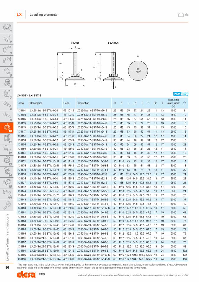
INOXLX-SST - LX-SST-S
Code Description Code Description D d L L1 l l1 l2 sMax. limit
static load* [N]
431101 LX.25-SW13-SST-M6x24 431101-S LX.25-SW13-SST-M6x26-S 25 M6 35 37 24 26 11 13 1500 8
431103 LX.25-SW13-SST-M6x34 431103-S LX.25-SW13-SST-M6x36-S 25 M6 45 47 34 36 11 13 1500 10
431105 LX.25-SW13-SST-M6x54 431105-S LX.25-SW13-SST-M6x56-S 25 M6 65 67 54 56 11 13 1500 14
431113 LX.25-SW13-SST-M8x22 431113-S LX.25-SW13-SST-M8x24-S 25 M8 35 37 24 26 11 13 2500 16
431115 LX.25-SW13-SST-M8x32 431115-S LX.25-SW13-SST-M8x34-S 25 M8 43 45 32 34 11 13 2500 10
431117 LX.25-SW13-SST-M8x52 431117-S LX.25-SW13-SST-M8x54-S 25 M8 63 65 52 54 11 13 2500 12
431151 LX.30-SW17-SST-M6x22 431151-S LX.30-SW17-SST-M6x24-S 30 M6 34 36 22 24 12 17 1500 14
431153 LX.30-SW17-SST-M6x32 431153-S LX.30-SW17-SST-M6x34-S 30 M6 44 46 32 34 12 17 1500 18
431155 LX.30-SW17-SST-M6x52 431155-S LX.30-SW17-SST-M6x54-S 30 M6 64 66 52 54 12 17 1500 22
431159 LX.30-SW17-SST-M8x21 431159-S LX.30-SW17-SST-M8x23-S 30 M8 33 35 21 23 12 17 2500 14
431161 LX.30-SW17-SST-M8x31 431161-S LX.30-SW17-SST-M8x33-S 30 M8 43 45 31 33 12 17 2500 16
431163 LX.30-SW17-SST-M8x51 431163-S LX.30-SW17-SST-M8x53-S 30 M8 63 65 51 53 12 17 2500 20
431171 LX.30-SW17-SST-M10x31 431171-S LX.30-SW17-SST-M10x33-S 30 M10 43 45 31 33 12 17 3000 17
431175 LX.30-SW17-SST-M10x51 431175-S LX.30-SW17-SST-M10x53-S 30 M10 63 65 51 53 12 17 3000 18
431179 LX.30-SW17-SST-M10x71 431179-S LX.30-SW17-SST-M10x73-S 30 M10 83 85 71 73 12 17 3000 20
431133 LX.40-SW17-SST-M8x20 431133-S LX.40-SW17-SST-M8x22-S 40 M8 32.5 34.5 19.5 21.5 13 17 2500 24
431135 LX.40-SW17-SST-M8x30 431135-S LX.40-SW17-SST-M8x32-S 40 M8 42.5 44.5 29.5 31.5 13 17 2500 28
431137 LX.40-SW17-SST-M8x50 431137-S LX.40-SW17-SST-M8x52-S 40 M8 62.5 64.5 49.5 51.5 13 17 2500 21
431142 LX.40-SW17-SST-M10x30 431142-S LX.40-SW17-SST-M10x32-S 40 M10 42.5 44.5 29.5 31.5 13 17 3000 22
431144 LX.40-SW17-SST-M10x50 431144-S LX.40-SW17-SST-M10x52-S 40 M10 62.5 64.5 49.5 51.5 13 17 3000 24
431146 LX.40-SW17-SST-M10x70 431146-S LX.40-SW17-SST-M10x72-S 40 M10 82.5 84.5 69.5 71.5 13 17 3000 26
431148 LX.40-SW17-SST-M12x50 431148-S LX.40-SW17-SST-M12x52-S 40 M12 62.5 64.5 49.5 51.5 13 17 5000 34
431149 LX.40-SW17-SST-M12x70 431149-S LX.40-SW17-SST-M12x72-S 40 M12 82.5 84.5 69.5 71.5 13 17 5000 40
431150 LX.40-SW17-SST-M12x100 431150-S LX.40-SW17-SST-M12x102-S 40 M12 112.5 114.5 99.5 101.5 13 17 5000 50
431181 LX.50-SW19-SST-M10x46 431181-S LX.50-SW19-SST-M10x48-S 50 M10 62.5 64.5 45.5 47.5 17 19 3000 64
431182 LX.50-SW19-SST-M10x66 431182-S LX.50-SW19-SST-M10x68-S 50 M10 82.5 84.5 65.5 67.5 17 19 3000 68
431183 LX.50-SW19-SST-M10x96 431183-S LX.50-SW19-SST-M10x98-S 50 M10 112.5 114.5 95.5 97.5 17 19 3000 75
431184 LX.50-SW19-SST-M12x46 431184-S LX.50-SW19-SST-M12x48-S 50 M12 62.5 64.5 45.5 47.5 17 19 5000 67
431185 LX.50-SW19-SST-M12x66 431185-S LX.50-SW19-SST-M12x68-S 50 M12 82.5 84.5 65.5 67.5 17 19 5000 72
431186 LX.50-SW19-SST-M12x96 431186-S LX.50-SW19-SST-M12x98-S 50 M12 112.5 114.5 95.5 97.5 17 19 5000 79
431191 LX.60-SW24-SST-M12x44 431191-S LX.60-SW24-SST-M12x46-S 60 M12 62.5 64.5 43.5 45.5 19 24 5000 67
431192 LX.60-SW24-SST-M12x64 431192-S LX.60-SW24-SST-M12x66-S 60 M12 82.5 84.5 63.5 65.5 19 24 5000 73
431193 LX.60-SW24-SST-M12x94 431193-S LX.60-SW24-SST-M12x96-S 60 M12 112.5 114.5 93.5 95.5 19 24 5000 82
431194 LX.60-SW24-SST-M16x64 431194-S LX.60-SW24-SST-M16x66-S 60 M16 82.5 84.5 63.5 65.5 19 24 7500 102
431195 LX.60-SW24-SST-M16x104 431195-S LX.60-SW24-SST-M16x106-S 60 M16 122.5 124.5 103.5 105.5 19 24 7500 132
431196 LX.60-SW24-SST-M16x144 431196-S LX.60-SW24-SST-M16x146-S 60 M16 162.5 164.5 143.5 145.5 19 24 7500 156
* The max static load is the value above which the load applied to the element may cause some plastic material breakage, in particular conditions of use. Obviously, a factor that takes into consideration the importance and the safety level of the specific application must be applied to this value.
LX
7/2018
Models all rights reserved in accordance with the law. Always mention the source when reproducing our drawings and photos.
87
Leve
lling
ele
men
ts a
nd s
uppo
rts
1
2
3
4
5
6
7
8
9
10
11
12
13
14
15
RH
4|5LX Levelling elements
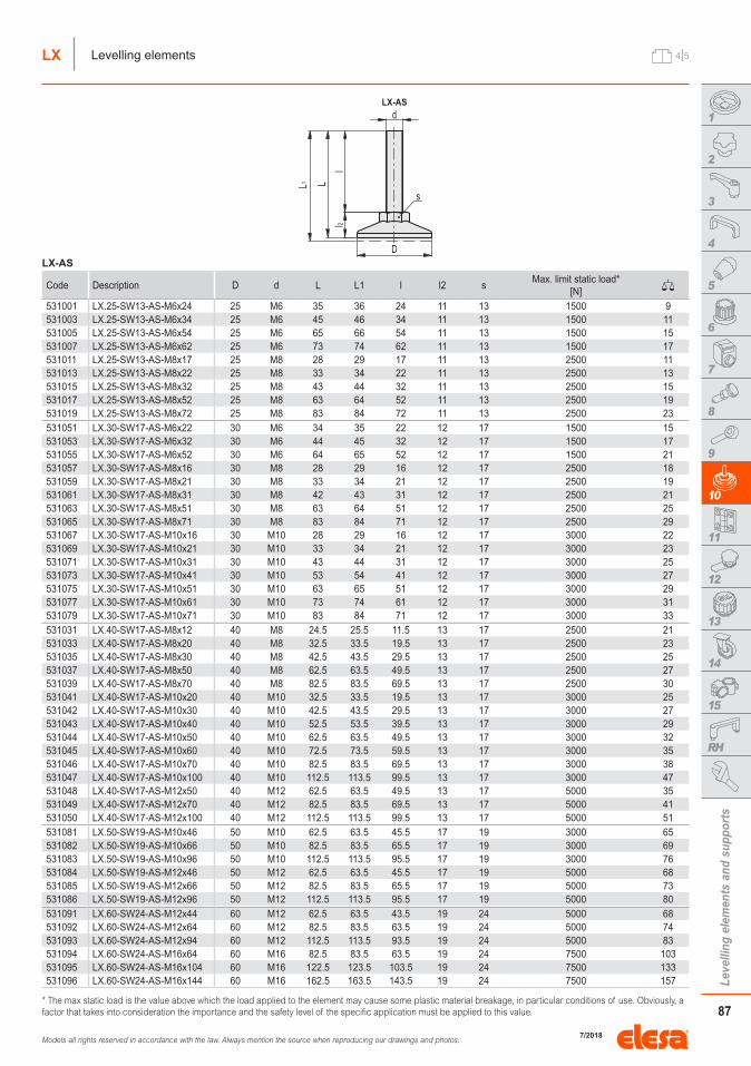
LX-AS
Code Description D d L L1 l l2 sMax. limit static load*
[N]531001 LX.25-SW13-AS-M6x24 25 M6 35 36 24 11 13 1500 9531003 LX.25-SW13-AS-M6x34 25 M6 45 46 34 11 13 1500 11531005 LX.25-SW13-AS-M6x54 25 M6 65 66 54 11 13 1500 15531007 LX.25-SW13-AS-M6x62 25 M6 73 74 62 11 13 1500 17531011 LX.25-SW13-AS-M8x17 25 M8 28 29 17 11 13 2500 11531013 LX.25-SW13-AS-M8x22 25 M8 33 34 22 11 13 2500 13531015 LX.25-SW13-AS-M8x32 25 M8 43 44 32 11 13 2500 15531017 LX.25-SW13-AS-M8x52 25 M8 63 64 52 11 13 2500 19531019 LX.25-SW13-AS-M8x72 25 M8 83 84 72 11 13 2500 23531051 LX.30-SW17-AS-M6x22 30 M6 34 35 22 12 17 1500 15531053 LX.30-SW17-AS-M6x32 30 M6 44 45 32 12 17 1500 17531055 LX.30-SW17-AS-M6x52 30 M6 64 65 52 12 17 1500 21531057 LX.30-SW17-AS-M8x16 30 M8 28 29 16 12 17 2500 18531059 LX.30-SW17-AS-M8x21 30 M8 33 34 21 12 17 2500 19531061 LX.30-SW17-AS-M8x31 30 M8 42 43 31 12 17 2500 21531063 LX.30-SW17-AS-M8x51 30 M8 63 64 51 12 17 2500 25531065 LX.30-SW17-AS-M8x71 30 M8 83 84 71 12 17 2500 29531067 LX.30-SW17-AS-M10x16 30 M10 28 29 16 12 17 3000 22531069 LX.30-SW17-AS-M10x21 30 M10 33 34 21 12 17 3000 23531071 LX.30-SW17-AS-M10x31 30 M10 43 44 31 12 17 3000 25531073 LX.30-SW17-AS-M10x41 30 M10 53 54 41 12 17 3000 27531075 LX.30-SW17-AS-M10x51 30 M10 63 65 51 12 17 3000 29531077 LX.30-SW17-AS-M10x61 30 M10 73 74 61 12 17 3000 31531079 LX.30-SW17-AS-M10x71 30 M10 83 84 71 12 17 3000 33531031 LX.40-SW17-AS-M8x12 40 M8 24.5 25.5 11.5 13 17 2500 21531033 LX.40-SW17-AS-M8x20 40 M8 32.5 33.5 19.5 13 17 2500 23531035 LX.40-SW17-AS-M8x30 40 M8 42.5 43.5 29.5 13 17 2500 25531037 LX.40-SW17-AS-M8x50 40 M8 62.5 63.5 49.5 13 17 2500 27531039 LX.40-SW17-AS-M8x70 40 M8 82.5 83.5 69.5 13 17 2500 30531041 LX.40-SW17-AS-M10x20 40 M10 32.5 33.5 19.5 13 17 3000 25531042 LX.40-SW17-AS-M10x30 40 M10 42.5 43.5 29.5 13 17 3000 27531043 LX.40-SW17-AS-M10x40 40 M10 52.5 53.5 39.5 13 17 3000 29531044 LX.40-SW17-AS-M10x50 40 M10 62.5 63.5 49.5 13 17 3000 32531045 LX.40-SW17-AS-M10x60 40 M10 72.5 73.5 59.5 13 17 3000 35531046 LX.40-SW17-AS-M10x70 40 M10 82.5 83.5 69.5 13 17 3000 38531047 LX.40-SW17-AS-M10x100 40 M10 112.5 113.5 99.5 13 17 3000 47531048 LX.40-SW17-AS-M12x50 40 M12 62.5 63.5 49.5 13 17 5000 35531049 LX.40-SW17-AS-M12x70 40 M12 82.5 83.5 69.5 13 17 5000 41531050 LX.40-SW17-AS-M12x100 40 M12 112.5 113.5 99.5 13 17 5000 51531081 LX.50-SW19-AS-M10x46 50 M10 62.5 63.5 45.5 17 19 3000 65531082 LX.50-SW19-AS-M10x66 50 M10 82.5 83.5 65.5 17 19 3000 69531083 LX.50-SW19-AS-M10x96 50 M10 112.5 113.5 95.5 17 19 3000 76531084 LX.50-SW19-AS-M12x46 50 M12 62.5 63.5 45.5 17 19 5000 68531085 LX.50-SW19-AS-M12x66 50 M12 82.5 83.5 65.5 17 19 5000 73531086 LX.50-SW19-AS-M12x96 50 M12 112.5 113.5 95.5 17 19 5000 80531091 LX.60-SW24-AS-M12x44 60 M12 62.5 63.5 43.5 19 24 5000 68531092 LX.60-SW24-AS-M12x64 60 M12 82.5 83.5 63.5 19 24 5000 74531093 LX.60-SW24-AS-M12x94 60 M12 112.5 113.5 93.5 19 24 5000 83531094 LX.60-SW24-AS-M16x64 60 M16 82.5 83.5 63.5 19 24 7500 103531095 LX.60-SW24-AS-M16x104 60 M16 122.5 123.5 103.5 19 24 7500 133531096 LX.60-SW24-AS-M16x144 60 M16 162.5 163.5 143.5 19 24 7500 157
* The max static load is the value above which the load applied to the element may cause some plastic material breakage, in particular conditions of use. Obviously, a factor that takes into consideration the importance and the safety level of the specific application must be applied to this value.
LX-AS
LX
7/2018
Models all rights reserved in accordance with the law. Always mention the source when reproducing our drawings and photos.
88
Leve
lling
ele
men
ts a
nd s
uppo
rts
1
2
3
4
5
6
7
8
9
10
11
12
13
14
15
RH
5|5LX Levelling elements
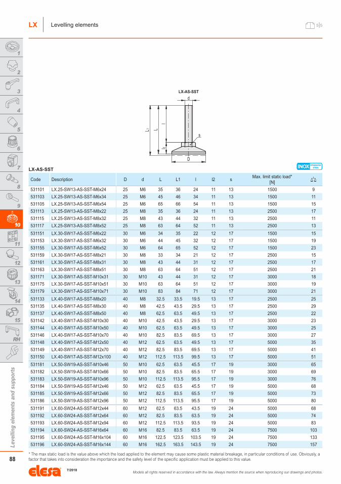
INOXLX-AS-SST
Code Description D d L L1 l l2 sMax. limit static load*
[N]
531101 LX.25-SW13-AS-SST-M6x24 25 M6 35 36 24 11 13 1500 9
531103 LX.25-SW13-AS-SST-M6x34 25 M6 45 46 34 11 13 1500 11
531105 LX.25-SW13-AS-SST-M6x54 25 M6 65 66 54 11 13 1500 15
531113 LX.25-SW13-AS-SST-M8x22 25 M8 35 36 24 11 13 2500 17
531115 LX.25-SW13-AS-SST-M8x32 25 M8 43 44 32 11 13 2500 11
531117 LX.25-SW13-AS-SST-M8x52 25 M8 63 64 52 11 13 2500 13
531151 LX.30-SW17-AS-SST-M6x22 30 M6 34 35 22 12 17 1500 15
531153 LX.30-SW17-AS-SST-M6x32 30 M6 44 45 32 12 17 1500 19
531155 LX.30-SW17-AS-SST-M6x52 30 M6 64 65 52 12 17 1500 23
531159 LX.30-SW17-AS-SST-M8x21 30 M8 33 34 21 12 17 2500 15
531161 LX.30-SW17-AS-SST-M8x31 30 M8 43 44 31 12 17 2500 17
531163 LX.30-SW17-AS-SST-M8x51 30 M8 63 64 51 12 17 2500 21
531171 LX.30-SW17-AS-SST-M10x31 30 M10 43 44 31 12 17 3000 18
531175 LX.30-SW17-AS-SST-M10x51 30 M10 63 64 51 12 17 3000 19
531179 LX.30-SW17-AS-SST-M10x71 30 M10 83 84 71 12 17 3000 21
531133 LX.40-SW17-AS-SST-M8x20 40 M8 32.5 33.5 19.5 13 17 2500 25
531135 LX.40-SW17-AS-SST-M8x30 40 M8 42.5 43.5 29.5 13 17 2500 29
531137 LX.40-SW17-AS-SST-M8x50 40 M8 62.5 63.5 49.5 13 17 2500 22
531142 LX.40-SW17-AS-SST-M10x30 40 M10 42.5 43.5 29.5 13 17 3000 23
531144 LX.40-SW17-AS-SST-M10x50 40 M10 62.5 63.5 49.5 13 17 3000 25
531146 LX.40-SW17-AS-SST-M10x70 40 M10 82.5 83.5 69.5 13 17 3000 27
531148 LX.40-SW17-AS-SST-M12x50 40 M12 62.5 63.5 49.5 13 17 5000 35
531149 LX.40-SW17-AS-SST-M12x70 40 M12 82.5 83.5 69.5 13 17 5000 41
531150 LX.40-SW17-AS-SST-M12x100 40 M12 112.5 113.5 99.5 13 17 5000 51
531181 LX.50-SW19-AS-SST-M10x46 50 M10 62.5 63.5 45.5 17 19 3000 65
531182 LX.50-SW19-AS-SST-M10x66 50 M10 82.5 83.5 65.5 17 19 3000 69
531183 LX.50-SW19-AS-SST-M10x96 50 M10 112.5 113.5 95.5 17 19 3000 76
531184 LX.50-SW19-AS-SST-M12x46 50 M12 62.5 63.5 45.5 17 19 5000 68
531185 LX.50-SW19-AS-SST-M12x66 50 M12 82.5 83.5 65.5 17 19 5000 73
531186 LX.50-SW19-AS-SST-M12x96 50 M12 112.5 113.5 95.5 17 19 5000 80
531191 LX.60-SW24-AS-SST-M12x44 60 M12 62.5 63.5 43.5 19 24 5000 68
531192 LX.60-SW24-AS-SST-M12x64 60 M12 82.5 83.5 63.5 19 24 5000 74
531193 LX.60-SW24-AS-SST-M12x94 60 M12 112.5 113.5 93.5 19 24 5000 83
531194 LX.60-SW24-AS-SST-M16x64 60 M16 82.5 83.5 63.5 19 24 7500 103
531195 LX.60-SW24-AS-SST-M16x104 60 M16 122.5 123.5 103.5 19 24 7500 133
531196 LX.60-SW24-AS-SST-M16x144 60 M16 162.5 163.5 143.5 19 24 7500 157
* The max static load is the value above which the load applied to the element may cause some plastic material breakage, in particular conditions of use. Obviously, a factor that takes into consideration the importance and the safety level of the specific application must be applied to this value.
LX-AS-SST
LX
7/2018
Related Documents