1 Paper No. 8/2017 LOCAL VESSELS ADVISORY COMMITTEE Amendment of the Codes of Practice - Safety Standards for Class I to III Vessels Purpose This paper sets out the Marine Department (MD)’s proposed amendments to the Code of Practice – Safety Standards for Class I Vessels 1 , Code of Practice – Safety Standards for Class II Vessels 2 and the Code of Practice – Safety Standards for Class III Vessels 3 (hereafter collectively referred as “CoPs”). Background 2. The abovementioned CoPs, which set out the safety standards for passenger carrying vessels, commercial vessels such as cargo vessels, etc. and fishing vessels were put in effect by gazette notices at beginning of this year. Since the CoPs are in operation MD continuously received comments from the industry and inspection personnels on the following areas: (a) certain standards are required to be modified to suit small vessels’ structural characteristics; (b) certain ambiguous provisions require clarifications; and (c) editorial errors. Proposal 3. Having consolidated and studied these comments MD proposes to amend the CoPs as set out in Annex 1; and with the draft of the involved chapters in complete in Annex 2. Sub-committee on Survey Work of Local Vessels 4. The proposed amendments to CoPs were endorsed by the Sub-committee on Survey Work of Local Vessels and Sub-committee on Class III Vessels respectively in the committee meetings on 23 May 2017 and 6 June 2017. The sub-committees agreed to submit the proposal to LVAC for deliberation. 1 http://www.mardep.gov.hk/en/pub_services/ocean/pdf/lvs_cop1.pdf 2 http://www.mardep.gov.hk/en/pub_services/ocean/pdf/lvs_cop2.pdf 3 http://www.mardep.gov.hk/en/pub_services/ocean/pdf/lvs_cop3.pdf

Welcome message from author
This document is posted to help you gain knowledge. Please leave a comment to let me know what you think about it! Share it to your friends and learn new things together.
Transcript

1
Paper No. 8/2017
LOCAL VESSELS ADVISORY COMMITTEE
Amendment of the Codes of Practice
- Safety Standards for Class I to III Vessels
Purpose
This paper sets out the Marine Department (MD)’s proposed amendments to
the Code of Practice – Safety Standards for Class I Vessels1, Code of Practice –
Safety Standards for Class II Vessels2 and the Code of Practice – Safety Standards
for Class III Vessels3 (hereafter collectively referred as “CoPs”).
Background
2. The abovementioned CoPs, which set out the safety standards for passenger
carrying vessels, commercial vessels such as cargo vessels, etc. and fishing vessels
were put in effect by gazette notices at beginning of this year. Since the CoPs are in
operation MD continuously received comments from the industry and inspection
personnels on the following areas:
(a) certain standards are required to be modified to suit small vessels’
structural characteristics;
(b) certain ambiguous provisions require clarifications; and
(c) editorial errors.
Proposal
3. Having consolidated and studied these comments MD proposes to amend
the CoPs as set out in Annex 1; and with the draft of the involved chapters in
complete in Annex 2.
Sub-committee on Survey Work of Local Vessels
4. The proposed amendments to CoPs were endorsed by the Sub-committee on
Survey Work of Local Vessels and Sub-committee on Class III Vessels respectively
in the committee meetings on 23 May 2017 and 6 June 2017. The sub-committees
agreed to submit the proposal to LVAC for deliberation.
1 http://www.mardep.gov.hk/en/pub_services/ocean/pdf/lvs_cop1.pdf
2 http://www.mardep.gov.hk/en/pub_services/ocean/pdf/lvs_cop2.pdf
3 http://www.mardep.gov.hk/en/pub_services/ocean/pdf/lvs_cop3.pdf
2
Way Forward
5. Subject to members’ views, MD will follow up the proposed amendments as
mentioned above.
Advice Sought
6. Members are invited to comment on the proposed amendments.
Local Vessels Safety Section
Marine Department
June 2017
p. I - 1
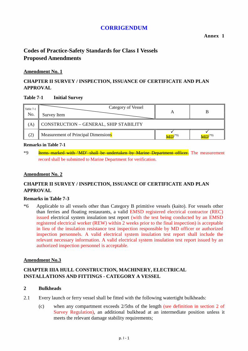
CORRIGENDUM Annex 1
Codes of Practice-Safety Standards for Class I Vessels Proposed Amendments Amendment No. 1
CHAPTER II SURVEY / INSPECTION, ISSUANCE OF CERTIFICATE AND PLAN APPROVAL
Table 7-1 Initial Survey
Table 7-1
No. Category of Vessel Survey Item A B
(A) CONSTRUCTION – GENERAL, SHIP STABILITY
(2) Measurement of Principal Dimensions MD(*9)
MD(*9)
Remarks in Table 7-1
*9 Items marked with ‘MD’ shall be undertaken by Marine Department officer. The measurement record shall be submitted to Marine Department for verification.
Amendment No. 2
CHAPTER II SURVEY / INSPECTION, ISSUANCE OF CERTIFICATE AND PLAN APPROVAL Remarks in Table 7-3 *6 Applicable to all vessels other than Category B primitive vessels (kaito). For vessels other
than ferries and floating restaurants, a valid EMSD registered electrical contractor (REC) issued electrical system insulation test report (with the test being conducted by an EMSD registered electrical worker (REW) within 2 weeks prior to the final inspection) is acceptable in lieu of the insulation resistance test inspection responsible by MD officer or authorized inspection personnels. A valid electrical system insulation test report shall include the relevant necessary information. A valid electrical system insulation test report issued by an authorized inspection personnel is acceptable.
Amendment No.3
CHAPTER IIIA HULL CONSTRUCTION, MACHINERY, ELECTRICAL INSTALLATIONS AND FITTINGS - CATEGORY A VESSEL 2 Bulkheads
2.1 Every launch or ferry vessel shall be fitted with the following watertight bulkheads:
(c) when any compartment exceeds 2/5ths of the length (see definition in section 2 of Survey Regulation), an additional bulkhead at an intermediate position unless it meets the relevant damage stability requirements;

p. I - 2
Amendment No.4
CHAPTER IIIA HULL CONSTRUCTION, MACHINERY, ELECTRICAL INSTALLATIONS AND FITTINGS - CATEGORY A VESSEL (English version only) 7.3 New main engines and gear boxes are required to be fitted on new vessels stated in section
7.1. For vessels other than those stated in section 7.1, if used engine is intended to be installed, it shall be properly stripped down and overhauled for examination. To facilitate the confirmation of the source of origin and/or the quality of reconditioning of the engines, proper document from the original engine maker or purchase document from the engine workshop shall be submitted. The data on engine model, type and identification number; the fuel injection pump model and size shall be clear and adequate for accurate assessment of the engine power. The reconditioning reports shall give adequate details similar or same as the items and format given on checklist of engine and gearbox inspection in Annex I-2 and I-3.
Amendment No.5
CHAPTER IIIB HULL CONSTRUCTION, MACHINERY, ELECTRICAL INSTALLATIONS AND FITTINGS - CATEGORY B VESSEL 2 Closing Appliances, Freeing Ports
Length (L) (m) Aggregate Freeing Port Area (m2)
L ≦12 0.0115L
12 < L < 24 (0.00146-0.006)L
L ≧24 0.029L
Amendment No.6
CHAPTER IV FREEBOARD AND STABILITY
1.5 Equivalent freeboard and stability criteria
1.5.1 Where it is not practical for any particular vessel, due to its geometric characteristics (e.g. the ratio of beam / depth is exceeding 2.5) or operating condition, to fully comply with the stipulated freeboard or stability criteria, the Department may permit the application of equivalent criteria which are at least as effective as that so specified.
1.5.2 For vessels of L<20m carrying ≤100passengers, the Department accepts the standard
applicable to vessels operating within sheltered waters, as stipulated in the Technical Regulation for the Survey of Coastal Boats promulgated by Maritime Safety Administration of the People’s Republic of China (MSA); or the equivalent. For vessels of L≥20m carrying ≤100passengers, the Department accepts the standard appropriate for vessels operating in Hong Kong waters, as promulgated by the MSA.
p. I - 3
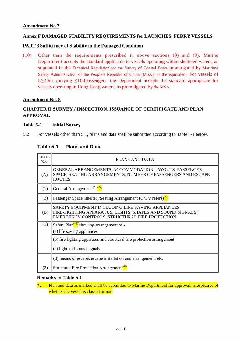
Amendment No.7
Annex F DAMAGED STABILITY REQUIREMENTS for LAUNCHES, FERRY VESSELS
PART 3 Sufficiency of Stability in the Damaged Condition
(10) Other than the requirements prescribed in above sections (8) and (9), Marine Department accepts the standard applicable to vessels operating within sheltered waters, as stipulated in the Technical Regulation for the Survey of Coastal Boats promulgated by Maritime Safety Administration of the People’s Republic of China (MSA); or the equivalent. For vessels of L≥20m carrying ≤100passengers, the Department accepts the standard appropriate for vessels operating in Hong Kong waters, as promulgated by the MSA.
Amendment No. 8
CHAPTER II SURVEY / INSPECTION, ISSUANCE OF CERTIFICATE AND PLAN APPROVAL
Table 5-1 Initial Survey
5.2 For vessels other than 5.1, plans and data shall be submitted according to Table 5-1 below.
Table 5-1 Plans and Data
Table 5-1
No. PLANS AND DATA
(A) GENERAL ARRANGEMENTS, ACCOMMODATION LAYOUTS, PASSENGER SPACE, SEATING ARRANGEMENTS, NUMBER OF PASSENGERS AND ESCAPE ROUTES
(1) General Arrangement (*1)(*2)
(2) Passenger Space (shelter)/Seating Arrangement (Ch. V refers)(*2)
(B) SAFETY EQUIPMENT INCLUDING LIFE-SAVING APPLIANCES, FIRE-FIGHTING APPARATUS, LIGHTS, SHAPES AND SOUND SIGNALS ; EMERGENCY CONTROLS, STRUCTURAL FIRE PROTECTION
(1) Safety Plan(*2))showing arrangement of - (a) life saving appliances
(b) fire fighting apparatus and structural fire protection arrangement
(c) light and sound signals
(d) means of escape, escape installation and arrangement, etc.
(2) Structural Fire Protection Arrangement(*2)
Remarks in Table 5-1
*2 Plan and data as marked shall be submitted to Marine Department for approval, irrespective of whether the vessel is classed or not.
p. II - 1
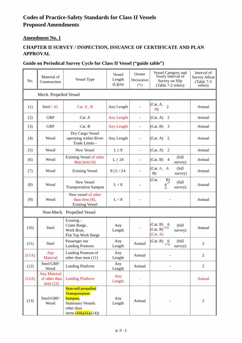
Codes of Practice-Safety Standards for Class II Vessels Proposed Amendments Amendment No. 1
CHAPTER II SURVEY / INSPECTION, ISSUANCE OF CERTIFICATE AND PLAN APPROVAL
Guide on Periodical Survey Cycle for Class II Vessel (“guide table”)
No. Material of
Construction Vessel Type Vessel Length (L)(m)
Owner Declaration
(*1)
Vessel Category and Yearly Interval of
Survey on Slip (Table 7-2 refers)
Interval of Survey Afloat
(Table 7-3 refers)
Mech. Propelled Vessel
(1) Steel / Al. Cat. A , B Any Length - (Cat. A, B) 2 Annual
(2) GRP Cat. A Any Length - (Cat. A) 2 Annual
(3) GRP Cat. B Any Length - (Cat. B) 3 Annual
(4) Wood Dry Cargo Vessel
operating within River Trade Limits -
Any Length - (Cat. A) 2 Annual
(5) Wood New Vessel L ≥ 8 - (Cat. A) 2 Annual
(6) Wood Existing Vessel of other than item (4) L ≥ 24 - (Cat. B) 4 (full
survey) Annual
(7) Wood Existing Vessel 8≤L<24 - (Cat. A, B)
6 (full survey) Annual
(8) Wood New Vessel Transportation Sampan L < 8 -
(Cat. B) 4 (*2)
(full survey) Annual
(9) Wood New vessel of other
than item (8), Existing Vessel
L < 8 - - Annual
Non-Mech. Propelled Vessel
(10) Steel
Existing - Crane Barge, Work Boat, Flat Top Work Barge
Any Length -
(Cat. B) 6 (Cat. B) (*2) (Cat. A)
(full survey) Annual
(11) Steel Passenger use Landing Pontoon
Any Length Annual (Cat. B) 6
(*2) (full
survey) 2
(11A) Any Material
Landing Pontoon of other than item (11)
Any Length Annual - 2
(12) Steel/GRP/ Wood Landing Platform Any
Length Annual - 2
(12A) Any Material of other than
item (12) Landing Platform Any
Length - Annual
(13) Steel/GRP/ Wood
Non-self propelled Transportation Sampan, Stationary Vessels other than items (10),(11),(14))
Any Length Annual - 2
p. II - 2
No. Material of
Construction Vessel Type Vessel Length (L)(m)
Owner Declaration
(*1)
Vessel Category and Yearly Interval of
Survey on Slip (Table 7-2 refers)
Interval of Survey Afloat
(Table 7-3 refers)
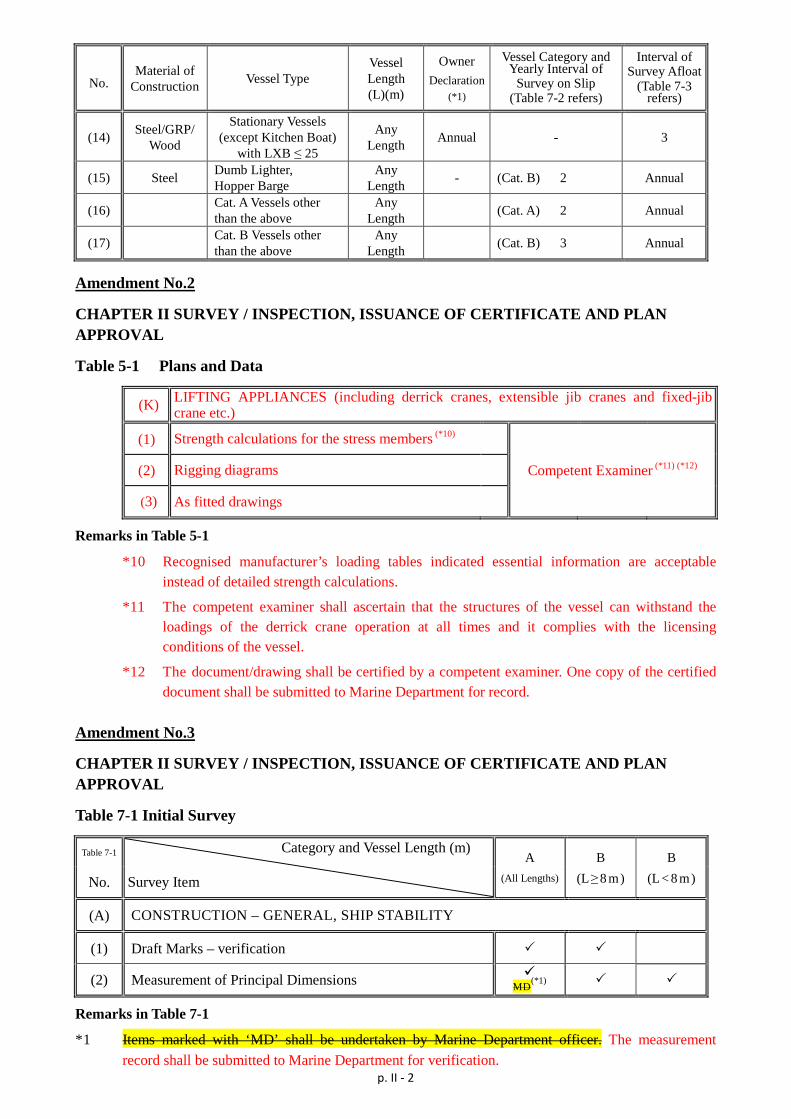
(14) Steel/GRP/ Wood
Stationary Vessels (except Kitchen Boat)
with LXB ≤ 25
Any Length Annual - 3
(15) Steel Dumb Lighter, Hopper Barge
Any Length - (Cat. B) 2 Annual
(16) Cat. A Vessels other than the above
Any Length (Cat. A) 2 Annual
(17) Cat. B Vessels other than the above
Any Length (Cat. B) 3 Annual
Amendment No.2
CHAPTER II SURVEY / INSPECTION, ISSUANCE OF CERTIFICATE AND PLAN APPROVAL
Table 5-1 Plans and Data
(K) LIFTING APPLIANCES (including derrick cranes, extensible jib cranes and fixed-jib crane etc.)
(1) Strength calculations for the stress members (*10)
(2) Rigging diagrams Competent Examiner (*11) (*12)
(3) As fitted drawings
Remarks in Table 5-1
*10 Recognised manufacturer’s loading tables indicated essential information are acceptable instead of detailed strength calculations.
*11 The competent examiner shall ascertain that the structures of the vessel can withstand the loadings of the derrick crane operation at all times and it complies with the licensing conditions of the vessel.
*12 The document/drawing shall be certified by a competent examiner. One copy of the certified document shall be submitted to Marine Department for record.
Amendment No.3
CHAPTER II SURVEY / INSPECTION, ISSUANCE OF CERTIFICATE AND PLAN APPROVAL
Table 7-1 Initial Survey
Table 7-1 Category and Vessel Length (m) Survey Item
A (All Lengths)
B (L≥8 m)
B (L< 8 m) No.
(A) CONSTRUCTION – GENERAL, SHIP STABILITY
(1) Draft Marks – verification
(2) Measurement of Principal Dimensions MD(*1)
Remarks in Table 7-1
*1 Items marked with ‘MD’ shall be undertaken by Marine Department officer. The measurement record shall be submitted to Marine Department for verification.
p. II - 3
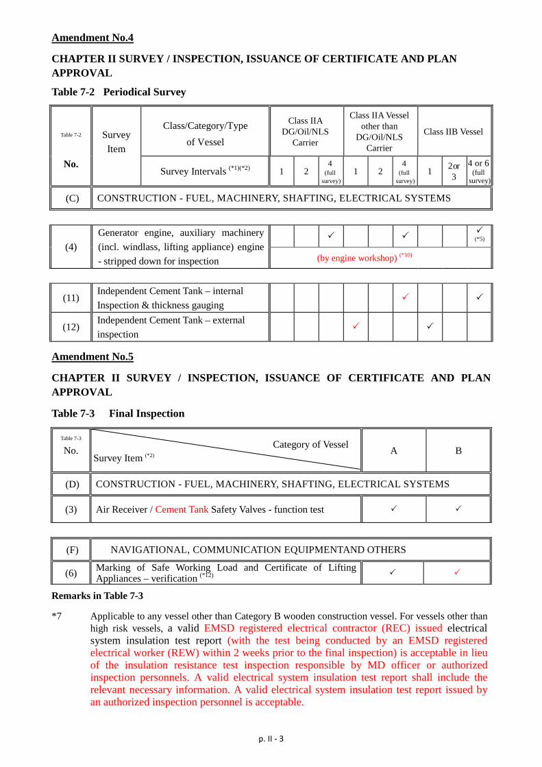
Amendment No.4
CHAPTER II SURVEY / INSPECTION, ISSUANCE OF CERTIFICATE AND PLAN APPROVAL
Table 7-2 Periodical Survey
Table 7-2 Survey Item
Class/Category/Type of Vessel
Class IIA DG/Oil/NLS
Carrier
Class IIA Vessel other than
DG/Oil/NLS Carrier
Class IIB Vessel
No. Survey Intervals (*1)(*2) 1 2
4 (full
survey) 1 2
4 (full
survey) 1 2 or
3 4 or 6
(full survey)
(C) CONSTRUCTION - FUEL, MACHINERY, SHAFTING, ELECTRICAL SYSTEMS
(4) Generator engine, auxiliary machinery (incl. windlass, lifting appliance) engine - stripped down for inspection
(*5) (by engine workshop) (*10)
(11) Independent Cement Tank – internal Inspection & thickness gauging
(12) Independent Cement Tank – external inspection
Amendment No.5
CHAPTER II SURVEY / INSPECTION, ISSUANCE OF CERTIFICATE AND PLAN APPROVAL
Table 7-3 Final Inspection
Table 7-3
No. Category of Vessel Survey Item (*2)
A B
(D) CONSTRUCTION - FUEL, MACHINERY, SHAFTING, ELECTRICAL SYSTEMS
(3) Air Receiver / Cement Tank Safety Valves - function test
(F) NAVIGATIONAL, COMMUNICATION EQUIPMENTAND OTHERS
(6) Marking of Safe Working Load and Certificate of Lifting Appliances – verification (*12)
Remarks in Table 7-3
*7 Applicable to any vessel other than Category B wooden construction vessel. For vessels other than high risk vessels, a valid EMSD registered electrical contractor (REC) issued electrical system insulation test report (with the test being conducted by an EMSD registered electrical worker (REW) within 2 weeks prior to the final inspection) is acceptable in lieu of the insulation resistance test inspection responsible by MD officer or authorized inspection personnels. A valid electrical system insulation test report shall include the relevant necessary information. A valid electrical system insulation test report issued by an authorized inspection personnel is acceptable.
p. II - 4
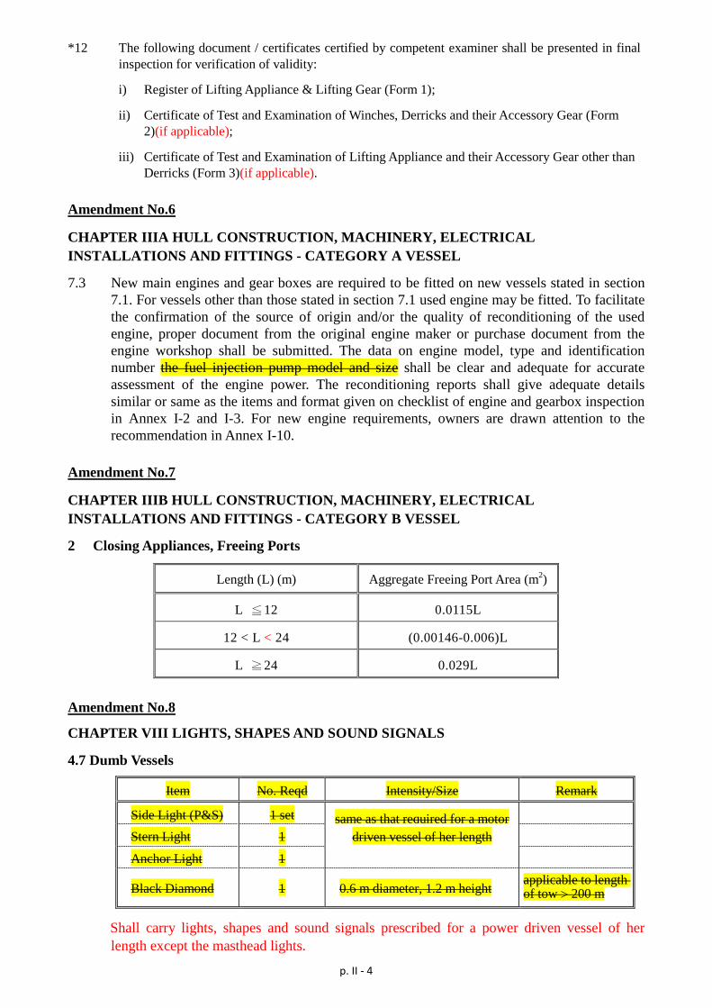
*12 The following document / certificates certified by competent examiner shall be presented in final inspection for verification of validity:
i) Register of Lifting Appliance & Lifting Gear (Form 1);
ii) Certificate of Test and Examination of Winches, Derricks and their Accessory Gear (Form 2)(if applicable);
iii) Certificate of Test and Examination of Lifting Appliance and their Accessory Gear other than Derricks (Form 3)(if applicable).
Amendment No.6
CHAPTER IIIA HULL CONSTRUCTION, MACHINERY, ELECTRICAL INSTALLATIONS AND FITTINGS - CATEGORY A VESSEL
7.3 New main engines and gear boxes are required to be fitted on new vessels stated in section 7.1. For vessels other than those stated in section 7.1 used engine may be fitted. To facilitate the confirmation of the source of origin and/or the quality of reconditioning of the used engine, proper document from the original engine maker or purchase document from the engine workshop shall be submitted. The data on engine model, type and identification number the fuel injection pump model and size shall be clear and adequate for accurate assessment of the engine power. The reconditioning reports shall give adequate details similar or same as the items and format given on checklist of engine and gearbox inspection in Annex I-2 and I-3. For new engine requirements, owners are drawn attention to the recommendation in Annex I-10.
Amendment No.7
CHAPTER IIIB HULL CONSTRUCTION, MACHINERY, ELECTRICAL INSTALLATIONS AND FITTINGS - CATEGORY B VESSEL
2 Closing Appliances, Freeing Ports
Length (L) (m) Aggregate Freeing Port Area (m2)
L ≦12 0.0115L
12 < L < 24 (0.00146-0.006)L
L ≧24 0.029L
Amendment No.8
CHAPTER VIII LIGHTS, SHAPES AND SOUND SIGNALS
4.7 Dumb Vessels
Item No. Reqd Intensity/Size Remark
Side Light (P&S) 1 set same as that required for a motor
Stern Light 1 driven vessel of her length
Anchor Light 1
Black Diamond 1 0.6 m diameter, 1.2 m height applicable to length of tow > 200 m
Shall carry lights, shapes and sound signals prescribed for a power driven vessel of her length except the masthead lights.
p. II - 5
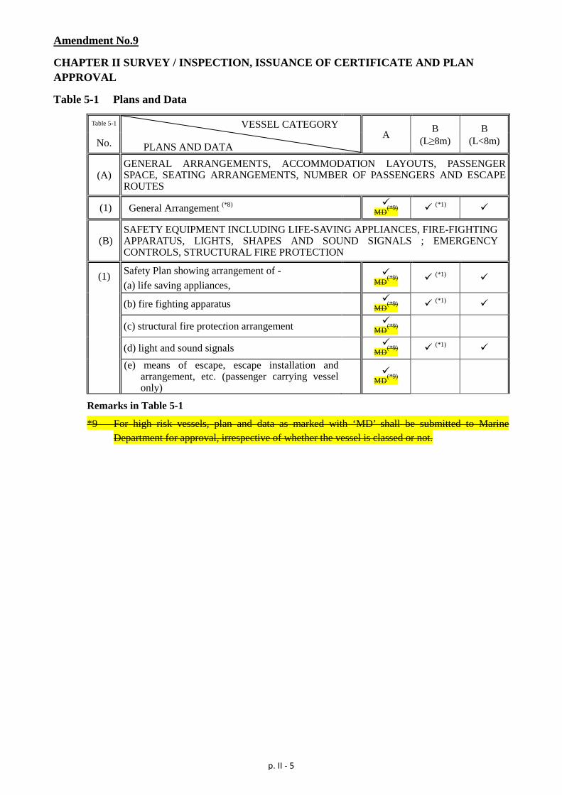
Amendment No.9
CHAPTER II SURVEY / INSPECTION, ISSUANCE OF CERTIFICATE AND PLAN APPROVAL
Table 5-1 Plans and Data
Table 5-1 VESSEL CATEGORY PLANS AND DATA
A B (L≥8m)
B (L<8m) No.
(A) GENERAL ARRANGEMENTS, ACCOMMODATION LAYOUTS, PASSENGER SPACE, SEATING ARRANGEMENTS, NUMBER OF PASSENGERS AND ESCAPE ROUTES
(1) General Arrangement (*8)
MD(*9) (*1)
(B) SAFETY EQUIPMENT INCLUDING LIFE-SAVING APPLIANCES, FIRE-FIGHTING APPARATUS, LIGHTS, SHAPES AND SOUND SIGNALS ; EMERGENCY CONTROLS, STRUCTURAL FIRE PROTECTION
(1) Safety Plan showing arrangement of - (a) life saving appliances,
MD(*9) (*1)
(b) fire fighting apparatus
MD(*9) (*1)
(c) structural fire protection arrangement
MD(*9)
(d) light and sound signals
MD(*9) (*1)
(e) means of escape, escape installation and
arrangement, etc. (passenger carrying vessel only)
MD(*9)
Remarks in Table 5-1
*9 For high risk vessels, plan and data as marked with ‘MD’ shall be submitted to Marine Department for approval, irrespective of whether the vessel is classed or not.
p. III - 1
Codes of Practice-Safety Standards for Class III Vessels Proposed Amendments Amendment No. 1
CHAPTER II SURVEY / INSPECTION, ISSUANCE OF CERTIFICATE AND PLAN APPROVAL
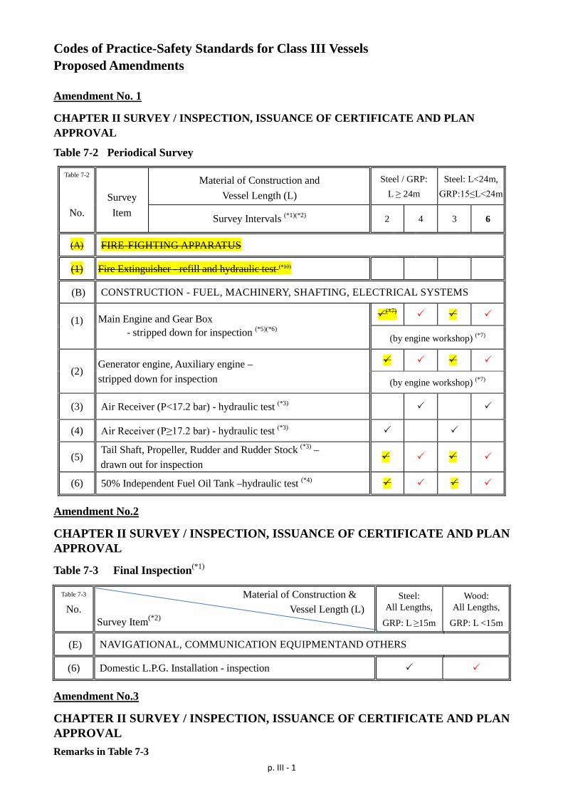
Table 7-2 Periodical Survey
Table 7-2
Survey Material of Construction and
Vessel Length (L) Steel / GRP:
L ≥ 24m Steel: L<24m,
GRP:15≤L<24m
No. Item Survey Intervals (*1)(*2) 2 4 3 6
(A) FIRE-FIGHTING APPARATUS
(1) Fire Extinguisher - refill and hydraulic test (*10)
(B) CONSTRUCTION - FUEL, MACHINERY, SHAFTING, ELECTRICAL SYSTEMS
(1)
Main Engine and Gear Box - stripped down for inspection (*5)(*6)
(*7)
(by engine workshop) (*7)
(2) Generator engine, Auxiliary engine – stripped down for inspection
(by engine workshop) (*7)
(3) Air Receiver (P<17.2 bar) - hydraulic test (*3)
(4) Air Receiver (P≥17.2 bar) - hydraulic test (*3)
(5) Tail Shaft, Propeller, Rudder and Rudder Stock (*3) – drawn out for inspection
(6) 50% Independent Fuel Oil Tank –hydraulic test (*4)
Amendment No.2
CHAPTER II SURVEY / INSPECTION, ISSUANCE OF CERTIFICATE AND PLAN APPROVAL
Table 7-3 Final Inspection(*1)
Table 7-3
No. Material of Construction &
Vessel Length (L) Survey Item(*2)
Steel: All Lengths,
GRP: L ≥15m
Wood: All Lengths,
GRP: L <15m
(E) NAVIGATIONAL, COMMUNICATION EQUIPMENTAND OTHERS
(6) Domestic L.P.G. Installation - inspection
Amendment No.3
CHAPTER II SURVEY / INSPECTION, ISSUANCE OF CERTIFICATE AND PLAN APPROVAL Remarks in Table 7-3
p. III - 2
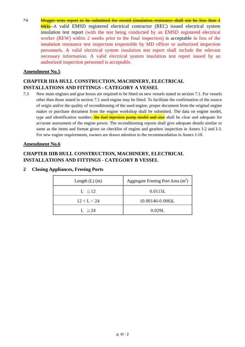
*4 Megger tests report to be submitted for record (insulation resistance shall not be less than 1 MΩ). A valid EMSD registered electrical contractor (REC) issued electrical system insulation test report (with the test being conducted by an EMSD registered electrical worker (REW) within 2 weeks prior to the final inspection) is acceptable in lieu of the insulation resistance test inspection responsible by MD officer or authorized inspection personnels. A valid electrical system insulation test report shall include the relevant necessary information. A valid electrical system insulation test report issued by an authorized inspection personnel is acceptable.
Amendment No.5
CHAPTER IIIA HULL CONSTRUCTION, MACHINERY, ELECTRICAL INSTALLATIONS AND FITTINGS - CATEGORY A VESSEL 7.3 New main engines and gear boxes are required to be fitted on new vessels stated in section 7.1. For vessels
other than those stated in section 7.1 used engine may be fitted. To facilitate the confirmation of the source of origin and/or the quality of reconditioning of the used engine, proper document from the original engine maker or purchase document from the engine workshop shall be submitted. The data on engine model, type and identification number; the fuel injection pump model and size shall be clear and adequate for accurate assessment of the engine power. The reconditioning reports shall give adequate details similar or same as the items and format given on checklist of engine and gearbox inspection in Annex I-2 and I-3. For new engine requirements, owners are drawn attention to the recommendation in Annex I-10.
Amendment No.6
CHAPTER IIIB HULL CONSTRUCTION, MACHINERY, ELECTRICAL INSTALLATIONS AND FITTINGS - CATEGORY B VESSEL
2 Closing Appliances, Freeing Ports
Length (L) (m) Aggregate Freeing Port Area (m2)
L ≦12 0.0115L
12 < L < 24 (0.00146-0.006)L
L ≧24 0.029L
DRAFT Annex 2
CODE OF PRACTICE ----
Safety Standards for Class I Vessels
(issued under Section 8 of the Merchant Shipping (Local Vessels) Ordinance, Cap 548) Local Vessels Safety Section Marine Department, HKSAR (June 2017 Edition)

Page II-1
CHAPTER II SURVEY / INSPECTION, ISSUANCE OF CERTIFICATE AND
PLAN APPROVAL
1 Survey / Inspection for Issue or Endorsement of Certificate
1.1 Any local vessel to which sections 7(1) and (3) of Survey Regulation apply when applying for an initial licence is subject to the approval of plans per items (appropriate according to category and type of vessel) indicated in Table 5-1.
1.2 Any local vessel to which Part 4 of Survey Regulation applies when applying for an initial licence is subject to the initial survey per items (appropriate according to category and type of vessel) indicated in Tables 7-1 and 7-3; and after licencing the periodical survey per items indicated in Tables 7-2 and 7-3.
1.3 Any licensed vessel of the above sections 1.1 or 1.2 intended for alteration shall be subject to the approval of plans (if section 1.1 is applicable) and survey relating to the alteration under section 76(5) of the Survey Regulation.
1.4 A replacement primitive vessel (kaito) carrying more than 60 passengers is required to comply with the standard of plan approval and survey as that for Class I vessel of type “Launch” carrying the same number of passengers.
1.5 Any vessel intended for change of the vessel’s name is subject to a survey relating to the change of name and the relevant fees.
1.6 A laid-up vessel (which is granted with a permission for laid-up) shall be subject to survey when returning to service if the Certificate of Survey previously issued has expired. If the expiry is not exceeding 2 years, the survey shall cover items due in the past 2 years as the vessel was not laid up.
1.7 Any vessel having its Certificate of Survey expired for more than 2 year but less than 8 years, the surveys shall follow the quadrennial survey programme prescribed in Table 7-2.
1.8 Any vessel having its Certificate of Survey expired for more than 8 years, it shall be subject to thorough inspection according to items of Table 7-1. If alterations had been carried out onboard vessel plans relating to the alterations shall be submitted for approval. The survey and plan approval are to comply with standards applicable to existing vessels, and the amended (if any).
1.9 When deemed necessary or at his discretion, the attending surveyor/inspector may request any other item to be presented for inspection
2 Statutory Surveys and Application
2.1 Subject to the below section 2.2 officers delegated by the Director are responsible for the statutory plan approval and survey of vessel.
2.2 The Director may delegate the statutory plan approval and surveys (items other than that marked with ‘MD’ and Table 7-3 (final inspection)) to Authorized Organization (AO)(see definition at Ch. I/3.1) as indicated in the authorization/recognition document. List of AOs will be promulgated in the Marine Department Notice issued from time to time. Vessel owner or agent, when required, may also apply to Marine Department for plan approval and surveys.
Page II-2
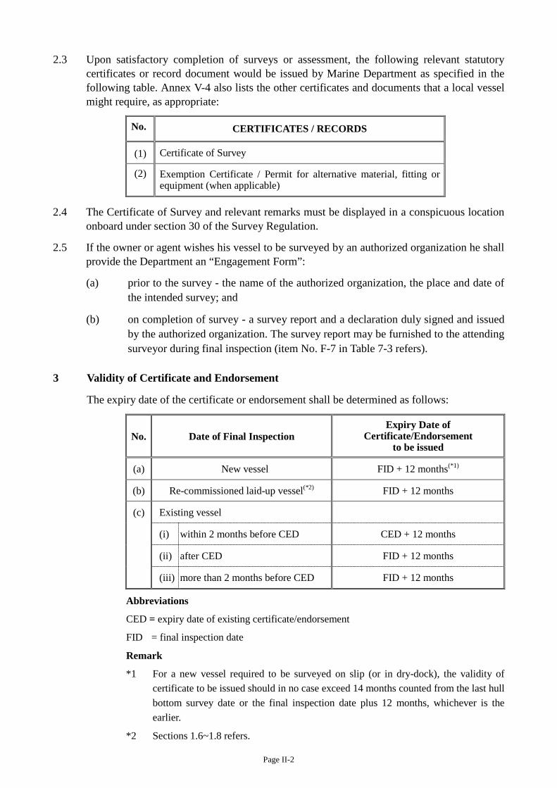
2.3 Upon satisfactory completion of surveys or assessment, the following relevant statutory certificates or record document would be issued by Marine Department as specified in the following table. Annex V-4 also lists the other certificates and documents that a local vessel might require, as appropriate:
No. CERTIFICATES / RECORDS
(1) Certificate of Survey
(2) Exemption Certificate / Permit for alternative material, fitting or equipment (when applicable)
2.4 The Certificate of Survey and relevant remarks must be displayed in a conspicuous location onboard under section 30 of the Survey Regulation.
2.5 If the owner or agent wishes his vessel to be surveyed by an authorized organization he shall provide the Department an “Engagement Form”:
(a) prior to the survey - the name of the authorized organization, the place and date of the intended survey; and
(b) on completion of survey - a survey report and a declaration duly signed and issued by the authorized organization. The survey report may be furnished to the attending surveyor during final inspection (item No. F-7 in Table 7-3 refers).
3 Validity of Certificate and Endorsement
The expiry date of the certificate or endorsement shall be determined as follows:
No. Date of Final Inspection Expiry Date of
Certificate/Endorsement to be issued
(a) New vessel FID + 12 months(*1)
(b) Re-commissioned laid-up vessel(*2) FID + 12 months
(c) Existing vessel
(i) within 2 months before CED CED + 12 months
(ii) after CED FID + 12 months
(iii) more than 2 months before CED FID + 12 months
Abbreviations
CED = expiry date of existing certificate/endorsement
FID = final inspection date
Remark
*1 For a new vessel required to be surveyed on slip (or in dry-dock), the validity of certificate to be issued should in no case exceed 14 months counted from the last hull bottom survey date or the final inspection date plus 12 months, whichever is the earlier.
*2 Sections 1.6~1.8 refers.
Page II-3
4 Submission of Plans and Data
4.1 Plans and data shall be submitted according to Table 5-1 (as marked with ""). Additional plans and data will be required when deemed necessary. The required plans and data may be consolidated into one plan (or plans) according to the size of vessel and complexities of the plan.
4.2 Except for any vessel classed with a classification society; and otherwise indicated in the table (items marked with ‘MD’), the plans and data may be submitted to any of the AO for approval at the discretion of the owner. For any vessel classed with a classification society, plans and data shall be submitted to the relevant classification society for approval.
4.3 For plans and data to be submitted for Marine Department’s approval, 3 copies of each shall be submitted for the 1st vessel of a series and 2 copies for the subsequent vessels.
4.4 One copy of such plans and data approved by AO shall be submitted to Marine Department for record. Supplementary plans and data may be required should any survey be undertaken by Marine Department.
4.5 Plans of General Arrangement, vessel construction and relevant plans shall be drawn in appropriate scale of legibly quality.
5 Plans and Data required to be submitted [Survey Regulation, section 9 refers]
5.1 For new primitive vessel (kaito) carrying not more than 60 passengers (Category B vessel), plans and data stipulated in Annex Q shall be submitted for approval.
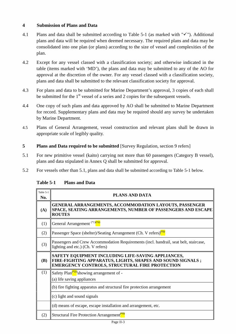
5.2 For vessels other than 5.1, plans and data shall be submitted according to Table 5-1 below.
Table 5-1 Plans and Data
Table 5-1
No. PLANS AND DATA
(A) GENERAL ARRANGEMENTS, ACCOMMODATION LAYOUTS, PASSENGER SPACE, SEATING ARRANGEMENTS, NUMBER OF PASSENGERS AND ESCAPE ROUTES
(1) General Arrangement (*1)(*2)
(2) Passenger Space (shelter)/Seating Arrangement (Ch. V refers)(*2)
(3) Passengers and Crew Accommodation Requirements (incl. handrail, seat belt, staircase, lighting and etc.) (Ch. V refers)
(B) SAFETY EQUIPMENT INCLUDING LIFE-SAVING APPLIANCES, FIRE-FIGHTING APPARATUS, LIGHTS, SHAPES AND SOUND SIGNALS ; EMERGENCY CONTROLS, STRUCTURAL FIRE PROTECTION
(1) Safety Plan(*2))showing arrangement of - (a) life saving appliances
(b) fire fighting apparatus and structural fire protection arrangement
(c) light and sound signals
(d) means of escape, escape installation and arrangement, etc.
(2) Structural Fire Protection Arrangement(*2)
Page II-4
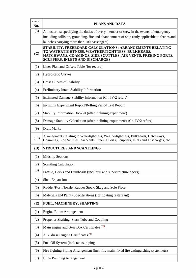
Table 5-1
No. PLANS AND DATA
(3) A muster list specifying the duties of every member of crew in the events of emergency including collision, grounding, fire and abandonment of ship (only applicable to ferries and launches carrying more than 100 passengers)
(C) STABILITY, FREEBOARD CALCULATIONS; ARRANGEMENTS RELATING TO WATERTIGHTNESS, WEATHERTIGHTNESS, BULKHEADS, HATCHWAYS, COAMINGS, SIDE SCUTTLES, AIR VENTS, FREEING PORTS, SCUPPERS, INLETS AND DISCHARGES
(1) Lines Plan and Offsets Table (for record)
(2) Hydrostatic Curves
(3) Cross Curves of Stability
(4) Preliminary Intact Stability Information
(5) Estimated Damage Stability Information (Ch. IV/2 refers)
(6) Inclining Experiment Report/Rolling Period Test Report
(7) Stability Information Booklet (after inclining experiment)
(8) Damage Stability Calculation (after inclining experiment) (Ch. IV/2 refers)
(9) Draft Marks
(10) Arrangements relating to Watertightness, Weathertightness, Bulkheads, Hatchways, Coamings, Side Scuttles, Air Vents, Freeing Ports, Scuppers, Inlets and Discharges, etc.
(D) STRUCTURES AND SCANTLINGS
(1) Midship Sections
(2) Scantling Calculation (3) Profile, Decks and Bulkheads (incl. hull and superstructure decks)
(4) Shell Expansion
(5) Rudder/Kort Nozzle, Rudder Stock, Skeg and Sole Piece
(6) Materials and Paints Specifications (for floating restaurant)
(E) FUEL, MACHINERY, SHAFTING
(1) Engine Room Arrangement
(2) Propeller Shafting, Stern Tube and Coupling
(3) Main engine and Gear Box Certificates (*2)
(4) Aux. diesel engine Certificates(*2)
(5) Fuel Oil System (incl. tanks, piping
(6) Fire-fighting Piping Arrangement (incl. fire main, fixed fire extinguishing system,etc)
(7) Bilge Pumping Arrangement
Page II-5
Table 5-1
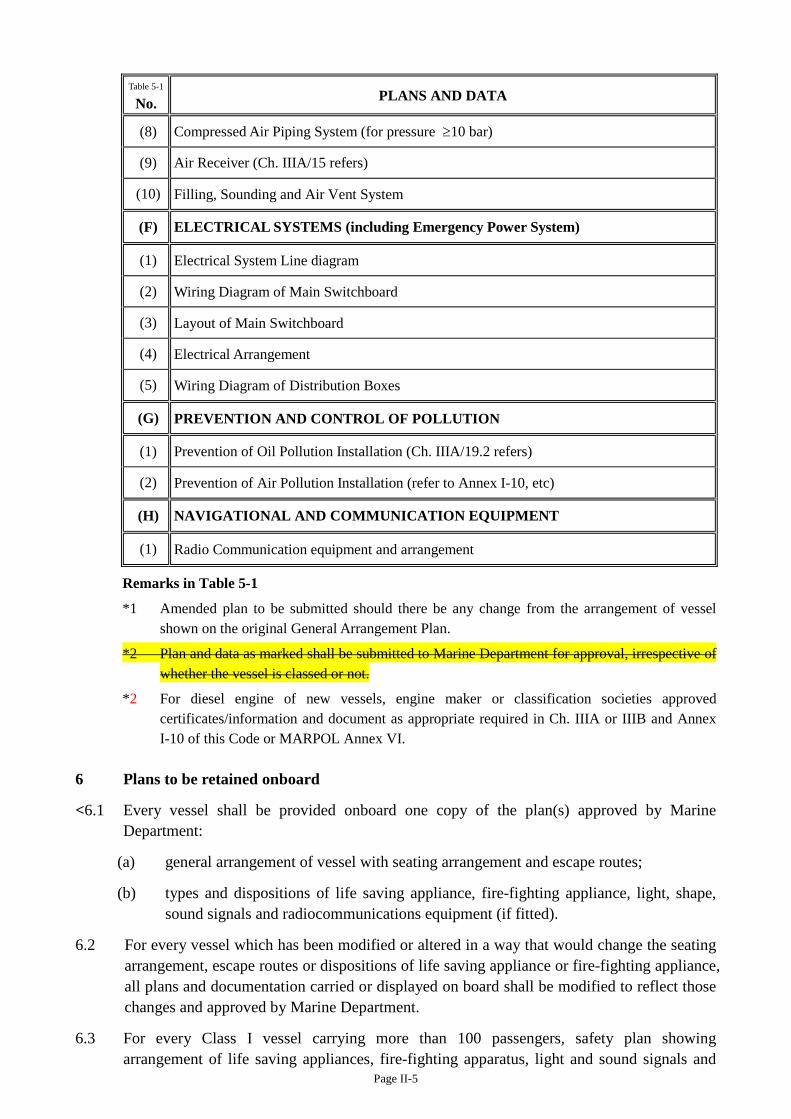
No. PLANS AND DATA
(8) Compressed Air Piping System (for pressure ≥10 bar)
(9) Air Receiver (Ch. IIIA/15 refers)
(10) Filling, Sounding and Air Vent System
(F) ELECTRICAL SYSTEMS (including Emergency Power System)
(1) Electrical System Line diagram
(2) Wiring Diagram of Main Switchboard
(3) Layout of Main Switchboard
(4) Electrical Arrangement
(5) Wiring Diagram of Distribution Boxes
(G) PREVENTION AND CONTROL OF POLLUTION
(1) Prevention of Oil Pollution Installation (Ch. IIIA/19.2 refers)
(2) Prevention of Air Pollution Installation (refer to Annex I-10, etc)
(H) NAVIGATIONAL AND COMMUNICATION EQUIPMENT
(1) Radio Communication equipment and arrangement
Remarks in Table 5-1
*1 Amended plan to be submitted should there be any change from the arrangement of vessel shown on the original General Arrangement Plan.
*2 Plan and data as marked shall be submitted to Marine Department for approval, irrespective of whether the vessel is classed or not.
*2 For diesel engine of new vessels, engine maker or classification societies approved certificates/information and document as appropriate required in Ch. IIIA or IIIB and Annex I-10 of this Code or MARPOL Annex VI.
6 Plans to be retained onboard
<6.1 Every vessel shall be provided onboard one copy of the plan(s) approved by Marine Department:
(a) general arrangement of vessel with seating arrangement and escape routes;
(b) types and dispositions of life saving appliance, fire-fighting appliance, light, shape, sound signals and radiocommunications equipment (if fitted).
6.2 For every vessel which has been modified or altered in a way that would change the seating arrangement, escape routes or dispositions of life saving appliance or fire-fighting appliance, all plans and documentation carried or displayed on board shall be modified to reflect those changes and approved by Marine Department.
6.3 For every Class I vessel carrying more than 100 passengers, safety plan showing arrangement of life saving appliances, fire-fighting apparatus, light and sound signals and
Page II-6
means of escape, escape installation and arrangement shall be exhibited in conspicuous places throughout the vessel.>
6.4 All ferries and launches carrying more than 100 passengers should have on board the muster list as stated in item (B)(3) of Table 5-1.
6.5 An emergency drill shall be practised by crewmembers at least once every two months. Records of emergency drills are to be kept onboard for at least one year for inspections by a MD officer.
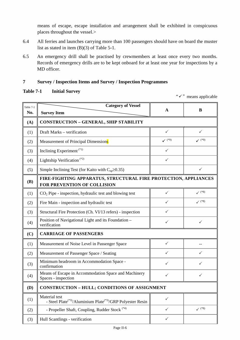
7 Survey / Inspection Items and Survey / Inspection Programmes
Table 7-1 Initial Survey “”means applicable
Table 7-1
No. Category of Vessel Survey Item A B
(A) CONSTRUCTION – GENERAL, SHIP STABILITY
(1) Draft Marks – verification
(2) Measurement of Principal Dimensions (*9) (*9)
(3) Inclining Experiment (*1)
(4) Lightship Verification (*2)
(5) Simple Inclining Test (for Kaito with Cnp≥0.35)
(B) FIRE-FIGHTING APPARATUS, STRUCTURAL FIRE PROTECTION, APPLIANCES FOR PREVENTION OF COLLISION
(1) CO2 Pipe - inspection, hydraulic test and blowing test (*8)
(2) Fire Main - inspection and hydraulic test (*8)
(3) Structural Fire Protection (Ch. VI/13 refers) - inspection
(4) Position of Navigational Light and its Foundation – verification
(C) CARRIAGE OF PASSENGERS
(1) Measurement of Noise Level in Passenger Space --
(2) Measurement of Passenger Space / Seating
(3) Minimum headroom in Accommodation Space - confirmation
(4) Means of Escape in Accommodation Space and Machinery Spaces - inspection
(D) CONSTRUCTION – HULL; CONDITIONS OF ASSIGNMENT
(1) Material test - Steel Plate(*3)/Aluminium Plate(*3)/GRP Polyester Resin
(2) - Propeller Shaft, Coupling, Rudder Stock (*4) (*8)
(3) Hull Scantlings - verification
Page II-7
Table 7-1
No. Category of Vessel Survey Item A B
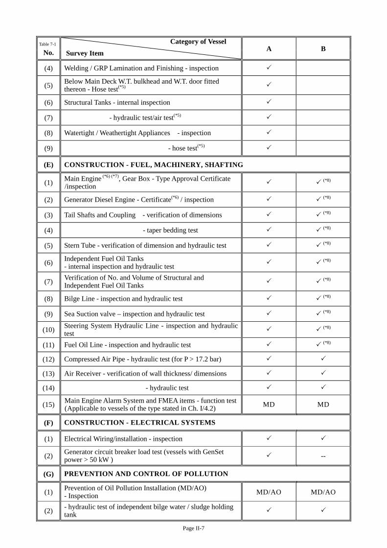
(4) Welding / GRP Lamination and Finishing - inspection
(5) Below Main Deck W.T. bulkhead and W.T. door fitted thereon - Hose test(*5)
(6) Structural Tanks - internal inspection
(7) - hydraulic test/air test(*5)
(8) Watertight / Weathertight Appliances - inspection
(9) - hose test(*5)
(E) CONSTRUCTION - FUEL, MACHINERY, SHAFTING
(1) Main Engine (*6) (*7), Gear Box - Type Approval Certificate /inspection (*8)
(2) Generator Diesel Engine - Certificate(*6) / inspection (*8)
(3) Tail Shafts and Coupling - verification of dimensions (*8)
(4) - taper bedding test (*8)
(5) Stern Tube - verification of dimension and hydraulic test (*8)
(6) Independent Fuel Oil Tanks - internal inspection and hydraulic test (*8)
(7) Verification of No. and Volume of Structural and Independent Fuel Oil Tanks (*8)
(8) Bilge Line - inspection and hydraulic test (*8)
(9) Sea Suction valve – inspection and hydraulic test (*8)
(10) Steering System Hydraulic Line - inspection and hydraulic test (*8)
(11) Fuel Oil Line - inspection and hydraulic test (*8)
(12) Compressed Air Pipe - hydraulic test (for P > 17.2 bar)
(13) Air Receiver - verification of wall thickness/ dimensions
(14) - hydraulic test
(15) Main Engine Alarm System and FMEA items - function test (Applicable to vessels of the type stated in Ch. I/4.2) MD MD
(F) CONSTRUCTION - ELECTRICAL SYSTEMS
(1) Electrical Wiring/installation - inspection
(2) Generator circuit breaker load test (vessels with GenSet power > 50 kW ) --
(G) PREVENTION AND CONTROL OF POLLUTION
(1) Prevention of Oil Pollution Installation (MD/AO) - Inspection MD/AO MD/AO
(2) - hydraulic test of independent bilge water / sludge holding tank
Page II-8
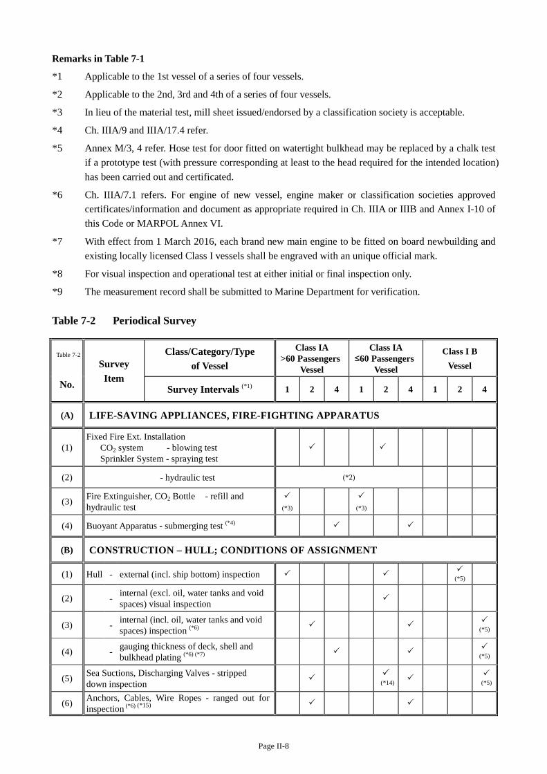
Remarks in Table 7-1
*1 Applicable to the 1st vessel of a series of four vessels.
*2 Applicable to the 2nd, 3rd and 4th of a series of four vessels.
*3 In lieu of the material test, mill sheet issued/endorsed by a classification society is acceptable.
*4 Ch. IIIA/9 and IIIA/17.4 refer.
*5 Annex M/3, 4 refer. Hose test for door fitted on watertight bulkhead may be replaced by a chalk test if a prototype test (with pressure corresponding at least to the head required for the intended location) has been carried out and certificated.
*6 Ch. IIIA/7.1 refers. For engine of new vessel, engine maker or classification societies approved certificates/information and document as appropriate required in Ch. IIIA or IIIB and Annex I-10 of this Code or MARPOL Annex VI.
*7 With effect from 1 March 2016, each brand new main engine to be fitted on board newbuilding and existing locally licensed Class I vessels shall be engraved with an unique official mark.
*8 For visual inspection and operational test at either initial or final inspection only.
*9 The measurement record shall be submitted to Marine Department for verification. Table 7-2 Periodical Survey
Table 7-2 Survey Item
Class/Category/Type of Vessel
Class IA >60 Passengers
Vessel
Class IA ≤60 Passengers
Vessel
Class I B Vessel
No. Survey Intervals (*1) 1 2 4 1 2 4 1 2 4
(A) LIFE-SAVING APPLIANCES, FIRE-FIGHTING APPARATUS
(1) Fixed Fire Ext. Installation CO2 system - blowing test Sprinkler System - spraying test
(2) - hydraulic test (*2)
(3) Fire Extinguisher, CO2 Bottle - refill and hydraulic test
(*3)
(*3)
(4) Buoyant Apparatus - submerging test (*4)
(B) CONSTRUCTION – HULL; CONDITIONS OF ASSIGNMENT
(1) Hull - external (incl. ship bottom) inspection (*5)
(2) - internal (excl. oil, water tanks and void spaces) visual inspection
(3) - internal (incl. oil, water tanks and void spaces) inspection (*6)
(*5)
(4) - gauging thickness of deck, shell and bulkhead plating (*6) (*7)
(*5)
(5) Sea Suctions, Discharging Valves - stripped down inspection
(*14) (*5)
(6) Anchors, Cables, Wire Ropes - ranged out for inspection (*6) (*15)
Page II-9
Table 7-2 Survey Item
Class/Category/Type of Vessel
Class IA >60 Passengers
Vessel
Class IA ≤60 Passengers
Vessel
Class I B Vessel
No. Survey Intervals (*1) 1 2 4 1 2 4 1 2 4
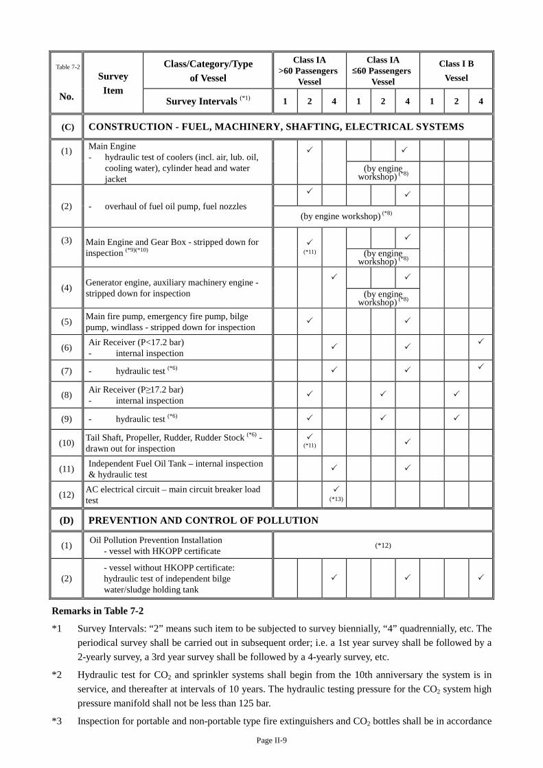
(C) CONSTRUCTION - FUEL, MACHINERY, SHAFTING, ELECTRICAL SYSTEMS
(1) Main Engine - hydraulic test of coolers (incl. air, lub. oil,
cooling water), cylinder head and water jacket
(by engine workshop) (*8)
(2) - overhaul of fuel oil pump, fuel nozzles
(by engine workshop) (*8)
(3)
Main Engine and Gear Box - stripped down for inspection (*9)(*10)
(*11) (by engine
workshop) (*8)
(4) Generator engine, auxiliary machinery engine - stripped down for inspection
(by engine workshop) (*8)
(5) Main fire pump, emergency fire pump, bilge pump, windlass - stripped down for inspection
(6) Air Receiver (P<17.2 bar) - internal inspection
(7) - hydraulic test (*6)
(8) Air Receiver (P≥17.2 bar) - internal inspection
(9) - hydraulic test (*6)
(10) Tail Shaft, Propeller, Rudder, Rudder Stock (*6) - drawn out for inspection
(*11)
(11) Independent Fuel Oil Tank – internal inspection & hydraulic test
(12) AC electrical circuit – main circuit breaker load test
(*13)
(D) PREVENTION AND CONTROL OF POLLUTION
(1) Oil Pollution Prevention Installation - vessel with HKOPP certificate
(*12)
(2) - vessel without HKOPP certificate:
hydraulic test of independent bilge water/sludge holding tank
Remarks in Table 7-2
*1 Survey Intervals: “2” means such item to be subjected to survey biennially, “4” quadrennially, etc. The periodical survey shall be carried out in subsequent order; i.e. a 1st year survey shall be followed by a 2-yearly survey, a 3rd year survey shall be followed by a 4-yearly survey, etc.
*2 Hydraulic test for CO2 and sprinkler systems shall begin from the 10th anniversary the system is in service, and thereafter at intervals of 10 years. The hydraulic testing pressure for the CO2 system high pressure manifold shall not be less than 125 bar.
*3 Inspection for portable and non-portable type fire extinguishers and CO2 bottles shall be in accordance
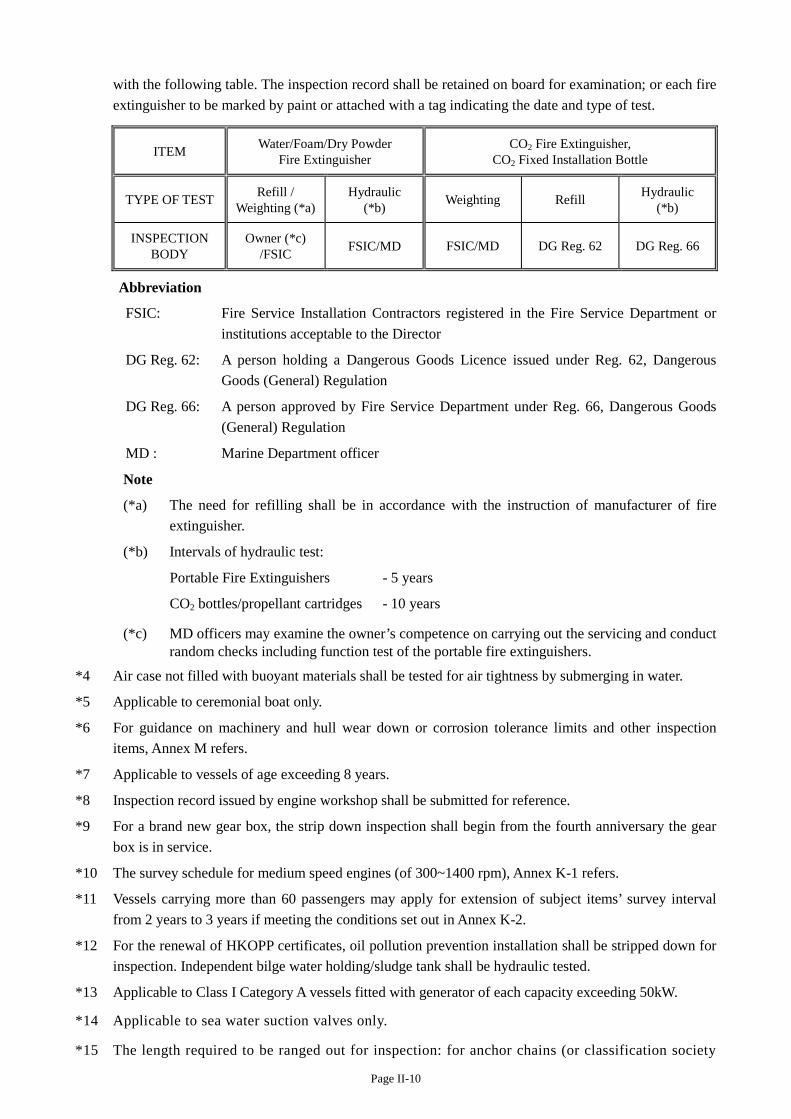
Page II-10
with the following table. The inspection record shall be retained on board for examination; or each fire extinguisher to be marked by paint or attached with a tag indicating the date and type of test.
ITEM Water/Foam/Dry Powder Fire Extinguisher
CO2 Fire Extinguisher, CO2 Fixed Installation Bottle
TYPE OF TEST Refill / Weighting (*a)
Hydraulic (*b) Weighting Refill Hydraulic
(*b)
INSPECTION BODY
Owner (*c) /FSIC FSIC/MD FSIC/MD DG Reg. 62 DG Reg. 66
Abbreviation
FSIC: Fire Service Installation Contractors registered in the Fire Service Department or institutions acceptable to the Director
DG Reg. 62: A person holding a Dangerous Goods Licence issued under Reg. 62, Dangerous Goods (General) Regulation
DG Reg. 66: A person approved by Fire Service Department under Reg. 66, Dangerous Goods (General) Regulation
MD : Marine Department officer
Note
(*a) The need for refilling shall be in accordance with the instruction of manufacturer of fire extinguisher.
(*b) Intervals of hydraulic test:
Portable Fire Extinguishers - 5 years
CO2 bottles/propellant cartridges - 10 years
(*c) MD officers may examine the owner’s competence on carrying out the servicing and conduct random checks including function test of the portable fire extinguishers.
*4 Air case not filled with buoyant materials shall be tested for air tightness by submerging in water.
*5 Applicable to ceremonial boat only.
*6 For guidance on machinery and hull wear down or corrosion tolerance limits and other inspection items, Annex M refers.
*7 Applicable to vessels of age exceeding 8 years.
*8 Inspection record issued by engine workshop shall be submitted for reference.
*9 For a brand new gear box, the strip down inspection shall begin from the fourth anniversary the gear box is in service.
*10 The survey schedule for medium speed engines (of 300~1400 rpm), Annex K-1 refers.
*11 Vessels carrying more than 60 passengers may apply for extension of subject items’ survey interval from 2 years to 3 years if meeting the conditions set out in Annex K-2.
*12 For the renewal of HKOPP certificates, oil pollution prevention installation shall be stripped down for inspection. Independent bilge water holding/sludge tank shall be hydraulic tested.
*13 Applicable to Class I Category A vessels fitted with generator of each capacity exceeding 50kW.
*14 Applicable to sea water suction valves only.
*15 The length required to be ranged out for inspection: for anchor chains (or classification society
Page II-11
accepted alternatives fitting) – whole length; for steel wire ropes – the whole length or a minimum length of 50m, whichever is the less. More or the whole length to be ranged out for inspection should there be major defect is found.
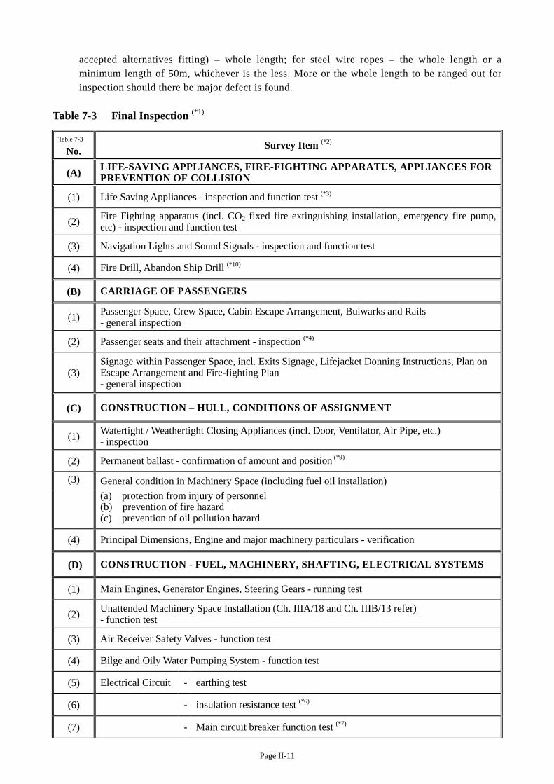
Table 7-3 Final Inspection (*1)
Table 7-3
No. Survey Item (*2)
(A) LIFE-SAVING APPLIANCES, FIRE-FIGHTING APPARATUS, APPLIANCES FOR PREVENTION OF COLLISION
(1) Life Saving Appliances - inspection and function test (*3)
(2) Fire Fighting apparatus (incl. CO2 fixed fire extinguishing installation, emergency fire pump, etc) - inspection and function test
(3) Navigation Lights and Sound Signals - inspection and function test
(4) Fire Drill, Abandon Ship Drill (*10)
(B) CARRIAGE OF PASSENGERS
(1) Passenger Space, Crew Space, Cabin Escape Arrangement, Bulwarks and Rails - general inspection
(2) Passenger seats and their attachment - inspection (*4)
(3) Signage within Passenger Space, incl. Exits Signage, Lifejacket Donning Instructions, Plan on Escape Arrangement and Fire-fighting Plan - general inspection
(C) CONSTRUCTION – HULL, CONDITIONS OF ASSIGNMENT
(1) Watertight / Weathertight Closing Appliances (incl. Door, Ventilator, Air Pipe, etc.) - inspection
(2) Permanent ballast - confirmation of amount and position (*9)
(3)
General condition in Machinery Space (including fuel oil installation) (a) protection from injury of personnel (b) prevention of fire hazard (c) prevention of oil pollution hazard
(4) Principal Dimensions, Engine and major machinery particulars - verification
(D) CONSTRUCTION - FUEL, MACHINERY, SHAFTING, ELECTRICAL SYSTEMS
(1) Main Engines, Generator Engines, Steering Gears - running test
(2) Unattended Machinery Space Installation (Ch. IIIA/18 and Ch. IIIB/13 refer) - function test
(3) Air Receiver Safety Valves - function test
(4) Bilge and Oily Water Pumping System - function test
(5) Electrical Circuit - earthing test
(6) - insulation resistance test (*6)
(7) - Main circuit breaker function test (*7)
Page II-12
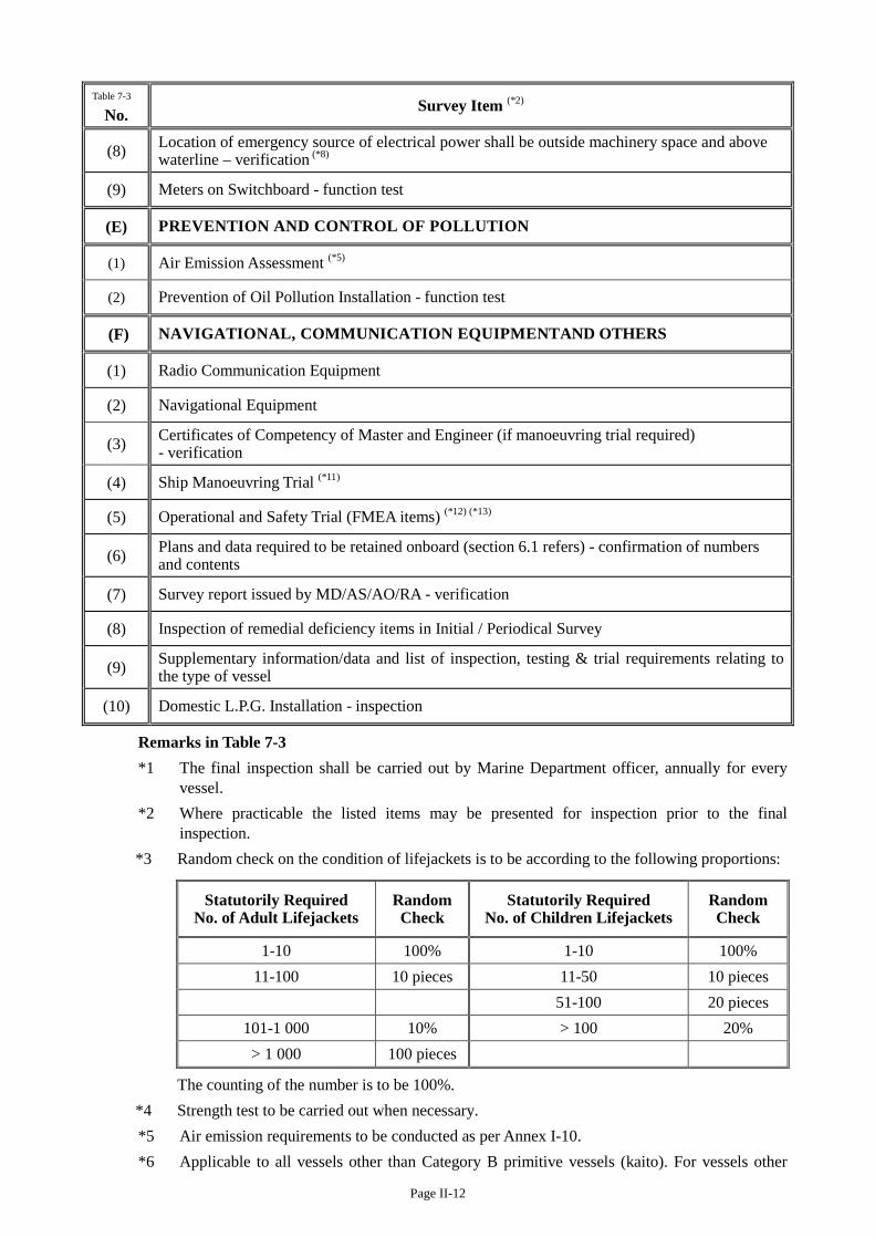
Table 7-3
No. Survey Item (*2)
(8) Location of emergency source of electrical power shall be outside machinery space and above waterline – verification (*8)
(9) Meters on Switchboard - function test
(E) PREVENTION AND CONTROL OF POLLUTION
(1) Air Emission Assessment (*5)
(2) Prevention of Oil Pollution Installation - function test
(F) NAVIGATIONAL, COMMUNICATION EQUIPMENTAND OTHERS
(1) Radio Communication Equipment
(2) Navigational Equipment
(3) Certificates of Competency of Master and Engineer (if manoeuvring trial required) - verification
(4) Ship Manoeuvring Trial (*11)
(5) Operational and Safety Trial (FMEA items) (*12) (*13)
(6) Plans and data required to be retained onboard (section 6.1 refers) - confirmation of numbers and contents
(7) Survey report issued by MD/AS/AO/RA - verification
(8) Inspection of remedial deficiency items in Initial / Periodical Survey
(9) Supplementary information/data and list of inspection, testing & trial requirements relating to the type of vessel
(10) Domestic L.P.G. Installation - inspection
Remarks in Table 7-3 *1 The final inspection shall be carried out by Marine Department officer, annually for every
vessel.
*2 Where practicable the listed items may be presented for inspection prior to the final inspection.
*3 Random check on the condition of lifejackets is to be according to the following proportions:
Statutorily Required No. of Adult Lifejackets
Random Check
Statutorily Required No. of Children Lifejackets
Random Check
1-10 100% 1-10 100% 11-100 10 pieces 11-50 10 pieces
51-100 20 pieces 101-1 000 10% > 100 20%
> 1 000 100 pieces
The counting of the number is to be 100%. *4 Strength test to be carried out when necessary. *5 Air emission requirements to be conducted as per Annex I-10. *6 Applicable to all vessels other than Category B primitive vessels (kaito). For vessels other
Page II-13
than ferries and floating restaurants, a valid EMSD registered electrical contractor (REC) issued electrical system insulation test report (with the test being conducted by an EMSD registered electrical worker (REW) within 2 weeks prior to the final inspection) is acceptable in lieu of the insulation resistance test inspection responsible by MD officer or authorized inspection personnels. A valid electrical system insulation test report shall include the relevant necessary information. A valid electrical system insulation test report issued by an authorized inspection personnel is acceptable.
*7 Applicable to any vessel fitted with generator of each capacity exceeding 50 kW. *8 Applicable to only a vessel which is still a new vessel when the reference to “the
commencement date of the Survey Regulation” in the definition of “new vessel” under Ch. I/3.1 is substituted by “29 November 2014”.
*9 In addition to the visual inspection, owner’s declaration on the amount and disposition of the ballast weights to be furnished to Marine Department for record.
*10 Applicable to launches, ferries and floating restaurants. The exact crew number indicated on the muster list shall participate in the drill.
*11 Applicable to ferry vessels only. The trial shall include crash ahead and astern running, turning and windlass operation test.
*12 Applicable to vessels of the type stated in Ch. I/4.2. *13 For vessels of the type stated in Ch. I/4.2, the certificate of competence or an eyesight
certificate (issued by a registered medical practitioner or registered optometrist) of the designated look-out (Ch. XII/11.1 refers) also to be verified.
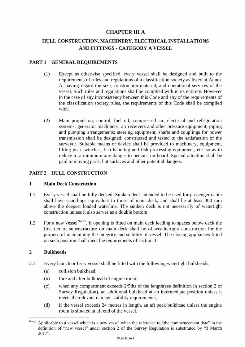
Page IIIA-1
CHAPTER III A
HULL CONSTRUCTION, MACHINERY, ELECTRICAL INSTALLATIONS
AND FITTINGS - CATEGORY A VESSEL
PART 1 GENERAL REQUIREMENTS
(1) Except as otherwise specified, every vessel shall be designed and built to the
requirements of rules and regulations of a classification society as listed at Annex
A, having regard the size, construction material, and operational services of the
vessel. Such rules and regulations shall be complied with in its entirety. However
in the case of any inconsistency between this Code and any of the requirements of
the classification society rules, the requirements of this Code shall be complied
with.
(2) Main propulsion, control, fuel oil, compressed air, electrical and refrigeration
systems; generator machinery; air receivers and other pressure equipment; piping
and pumping arrangements; steering equipment, shafts and couplings for power
transmission shall be designed, constructed and tested to the satisfaction of the
surveyor. Suitable means or device shall be provided to machinery, equipment,
lifting gear, winches, fish handling and fish processing equipment, etc. so as to
reduce to a minimum any danger to persons on board. Special attention shall be
paid to moving parts, hot surfaces and other potential dangers.
PART 2 HULL CONSTRUCTION
1 Main Deck Construction
1.1 Every vessel shall be fully decked. Sunken deck intended to be used for passenger cabin
shall have scantlings equivalent to those of main deck, and shall be at least 300 mm
above the deepest loaded waterline. The sunken deck is not necessarily of watertight
construction unless it also serves as a double bottom.
1.2 For a new vesselNote1
, if opening is fitted on main deck leading to spaces below deck the
first tier of superstructure on main deck shall be of weathertight construction for the
purpose of maintaining the integrity and stability of vessel. The closing appliances fitted
on such position shall meet the requirements of section 3.
2 Bulkheads
2.1 Every launch or ferry vessel shall be fitted with the following watertight bulkheads:
(a) collision bulkhead;
(b) fore and after bulkhead of engine room;
(c) when any compartment exceeds 2/5ths of the length(see definition in section 2 of
Survey Regulation), an additional bulkhead at an intermediate position unless it
meets the relevant damage stability requirements;
(d) if the vessel exceeds 24 metres in length, an aft peak bulkhead unless the engine
room is situated at aft end of the vessel.
Note1
Applicable to a vessel which is a new vessel when the reference to “the commencement date” in the
definition of “new vessel” under section 2 of the Survey Regulation is substituted by “3 March
2017”.
Page IIIA-2
2.2 In double-ended vessels, collision bulkheads shall be fitted at both ends.
2.3 On a motor vessel other than launch and ferry vessel, the dispositions and construction of
watertight bulkheads shall meet the relevant requirements of classification societies.
2.4 On all vessels other than wooden vessels, and as far as practicable on wooden vessels,
bulkheads shall be of watertight construction.
2.5 Access openings fitted in watertight bulkheads shall be equipped with effective
watertight closing appliances and shall meet the requirements of section 2.6.
2.6 The design of the watertight doors shall comply with the following requirements:
(a) The dimension of the watertight doors shall suit the design of the vessels;
(b) The warning “Door must be kept closed when underway” shall be marked on both
sides of the watertight door;
(c) For hinged type watertight door, they shall be opened outward except those doors
in high flooding risk spaces shall be opened into the space; and
(d) Watertight doors to be fitted with visual and audio alarms in the wheelhouse to give
alerts when watertight doors are open.
3 Closing Appliances, Freeing Ports
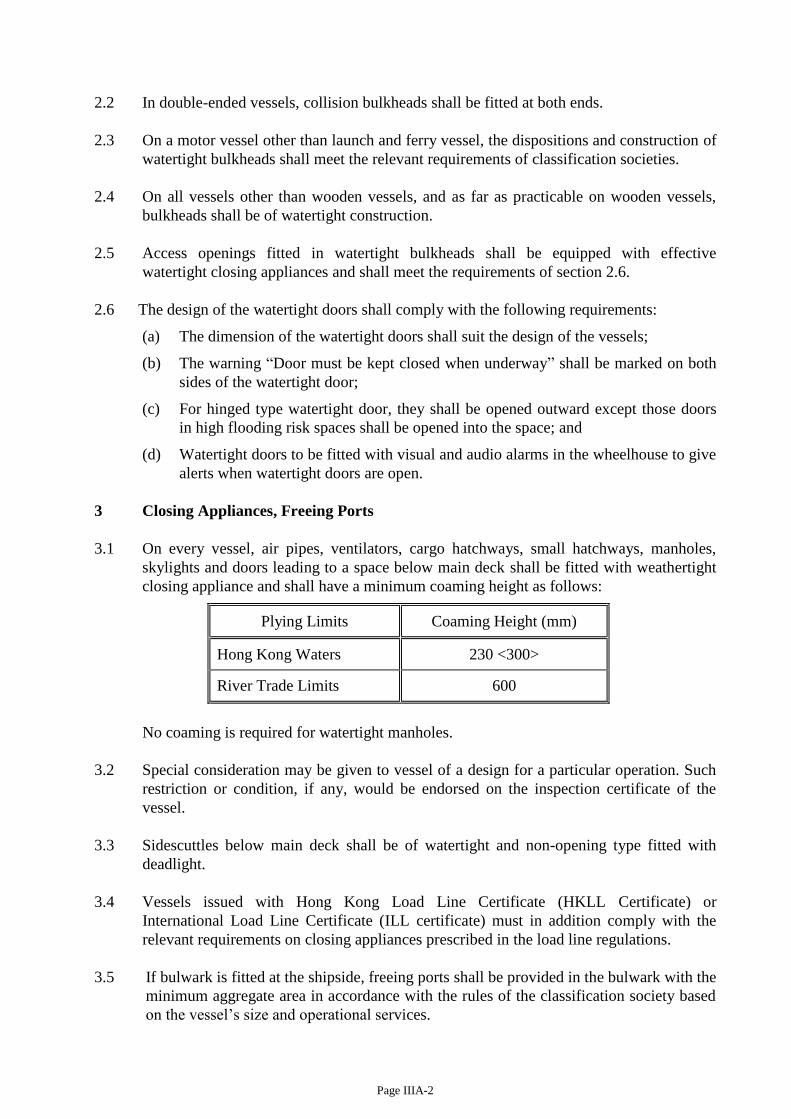
3.1 On every vessel, air pipes, ventilators, cargo hatchways, small hatchways, manholes,
skylights and doors leading to a space below main deck shall be fitted with weathertight
closing appliance and shall have a minimum coaming height as follows:
Plying Limits Coaming Height (mm)
Hong Kong Waters 230 <300>
River Trade Limits 600
No coaming is required for watertight manholes.
3.2 Special consideration may be given to vessel of a design for a particular operation. Such
restriction or condition, if any, would be endorsed on the inspection certificate of the
vessel.
3.3 Sidescuttles below main deck shall be of watertight and non-opening type fitted with
deadlight.
3.4 Vessels issued with Hong Kong Load Line Certificate (HKLL Certificate) or
International Load Line Certificate (ILL certificate) must in addition comply with the
relevant requirements on closing appliances prescribed in the load line regulations.
3.5 If bulwark is fitted at the shipside, freeing ports shall be provided in the bulwark with the
minimum aggregate area in accordance with the rules of the classification society based
on the vessel’s size and operational services.
Page IIIA-3
4 Protection of Passengers and Crew
4.1 Bulwark, guardrails or equivalent shall be installed near the periphery of weather decks
accessible to passengers and crew. Storm rails or handgrips shall be fitted in passenger
standing areas, fixed at deck or at wall.
4.2 Bulwarks and rails shall have a minimum height of 1000 mm above deck. Where it can
be shown that higher rails would interfere with the normal operation of the vessel a
reduced height may be accepted. Sufficient freeing ports are to be provided on bulwarks.
When guardrails are fitted, the opening below the lowest course of the rails shall not
exceed 230 mm and the other courses shall not be more than 380 mm apart.
4.3 Vessels issued with HKLL Certificate or ILL Certificate msut be in addition comply with
relevant requirements on means of protection prescribed in the load line regulations.
5 Flooring
Metallic or wooden flooring, if fitted above bilge, shall be readily removable for cleaning
and inspection. A steel inner bottom, if fitted, shall meet the requirements of
classification society rules in respect of double bottom. Access openings and air pipes
shall be provided for such spaces.
6 Marking of Hull
6.1 The certificate of ownership number of a vessel must be marked in accordance with
section 38 of the Merchant Shipping (Local Vessels) (Certification and Licensing)
Regulation.
6.2 On every launch and ferry vessel, the name of vessel (if any, as that shown on vessel’s
Certificate of Survey) and the total number of persons (passenger and crew) shall be
painted on vessel's bows and stern. The minimum size of lettering is 100 mm in height.
6.3 Permanent draft marks shall be provided on port and starboard side of stem and stern of a
vessel. The marks shall be measured from the bottom of the keel, with letters and figures
being in decimetric heights and at two decimetric intervals.
PART 3 MACHINERY INSTALLATION
7 Main Engine, Auxiliary Engine and Gear Box
7.1 In any launch or ferry vessel carrying more than 60 passengers; which is not classed with
a classification society and has main engine power output exceeding 130 kW, such main
engine and its associated gear box shall be of a type approved by a classification society
or maritime administration.
7.2 The main engine and the associated gearbox shall be matched at the maximum
continuous rating condition. Alternative rating may be accepted subject to proper
justification is given.
7.3 New main engines and gear boxes are required to be fitted on new vessels stated in
section 7.1. For vessels other than those stated in section 7.1, if used engine is intended to
be installed, it shall be properly stripped down and overhauled for examination. To
Page IIIA-4
facilitate the confirmation of the source of origin and/or the quality of reconditioning of
the engines, proper document from the original engine maker or purchase document from
the engine workshop shall be submitted. The data on engine model, type and
identification number shall be clear and adequate for accurate assessment of the engine
power. The reconditioning reports shall give adequate details similar or same as the items
and format given on checklist of engine and gearbox inspection in Annex I-2 and I-3.
For new engine requirements, owners are drawn attention to the recommendation in
Annex I-10.
Vessels built on or after 1 June 2008 but before 1 July 2016 may be fitted with Tier I
engine; vessels built on or after 1 July 2016 must be fitted with Tier II engine.
7.4 For main engine and gear box fitted on vessel other than that stated in section 7.1,
documentation provided by manufacturer indicating that the main engines are of marine
type is sufficient.
7.5 Auxiliary engine(s) on new mechanically propelled vessel shall be ‘marine type’;
auxiliary engine(s) on existing mechanically propelled vessel shall also be ‘marine type’
if they are being replaced/renewed.
7.6. Any engine fitted on a vessel shall be properly maintained at all times free from dark
smoke emission. In this regard, during the final inspection for initial and periodic survey,
engine performance condition check would include smoke emission test using
Ringelmann Chart. Shade 2 of the Ringelmann Chart and a continuous period of 3
minutes are the upper limits. The emission beyond this limit is considered as a
contravention of the law.
7.7 Any vessel if found or reported emitting excessive dark smoke, owners would be
requested to present vessel’s engine(s) for special inspection and smoke test to ensure
compliance. Any non-compliance will be pursued in accordance with relevant legislation
requirement.
7.8 If replacement of main engine, generator set, etc. are required, owner shall refer to the
requirements as indicated in Annex I-5A, I-5B and I-5C.
8 Engine Fittings
8.1 Main engine and generator engine shall be provided with effective means of control and
indication.
8.2 If remote control of main engine is provided from the wheelhouse, local control shall also
be provided at engine side.
< 8.3 Emergency stopping device for main engine shall be provided in wheelhouse. >
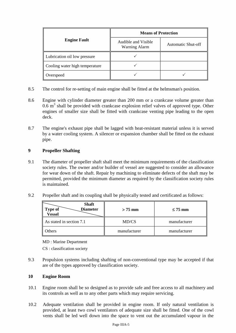
8.4 Main engine installed on any <launch or ferry vessel carrying more than 60 passengers>
shall be provided with means of protection due to engine faults as follows:
Page IIIA-5
Engine Fault
Means of Protection
Audible and Visible
Warning Alarm Automatic Shut-off
Lubrication oil low pressure
Cooling water high temperature
Overspeed
8.5 The control for re-setting of main engine shall be fitted at the helmsman's position.
8.6 Engine with cylinder diameter greater than 200 mm or a crankcase volume greater than
0.6 m3 shall be provided with crankcase explosion relief valves of approved type. Other
engines of smaller size shall be fitted with crankcase venting pipe leading to the open
deck.
8.7 The engine's exhaust pipe shall be lagged with heat-resistant material unless it is served
by a water cooling system. A silencer or expansion chamber shall be fitted on the exhaust
pipe.
9 Propeller Shafting
9.1 The diameter of propeller shaft shall meet the minimum requirements of the classification
society rules. The owner and/or builder of vessel are suggested to consider an allowance
for wear down of the shaft. Repair by machining to eliminate defects of the shaft may be
permitted, provided the minimum diameter as required by the classification society rules
is maintained.
9.2 Propeller shaft and its coupling shall be physically tested and certificated as follows:
Shaft
Type of Diameter
Vessel
75 mm
75 mm
As stated in section 7.1 MD/CS manufacturer
Others manufacturer manufacturer
MD : Marine Department
CS : classification society
9.3 Propulsion systems including shafting of non-conventional type may be accepted if that
are of the types approved by classification society.
10 Engine Room
10.1 Engine room shall be so designed as to provide safe and free access to all machinery and
its controls as well as to any other parts which may require servicing.
10.2 Adequate ventilation shall be provided in engine room. If only natural ventilation is
provided, at least two cowl ventilators of adequate size shall be fitted. One of the cowl
vents shall be led well down into the space to vent out the accumulated vapour in the
Page IIIA-6
lower part of the space. Ventilation trunk if passing through other compartments shall be
of watertight or gastight construction and structurally protectedNote 1
, as appropriate. The
ventilator shall be fitted with a fire damper or other means of closing. If a fire damper is
fitted, an indicator shall be provided to show whether the damper is in the open or close
position. The fire damper may be of manual type and the indicator which could be in
written form or other physical means, and be installed locally in the vicinity of fire
damper.
10.3 If the vessel is constructed of wooden or GRP of non-oil resistant material, a suitable
metal tray which can readily be cleaned shall be fitted under the engine to protect the
bilges against saturation by oil.
10.4 Two means of escape including suitable ladders and exits shall be provided for the engine
room. One of these means of escape may be waived with regard to the size and
disposition of the space. Any vessel permitted to be operated by combined coxswain and
engine operator (Ch. XII/3 refers) and of length less than 24 metres, one means of escape
can be waived.
If such means of escape is led to passenger space, it shall be clear of any seating.
10.5 Every machinery spaces shall be at all times kept clean and free from unnecessary
combustible materials and that waste oil is not allowed to accumulate in the bilges.
11 Nature of Fuel
Except otherwise permitted by the Director, marine fuel oil of flash point of less than
60oC (closed cup test) must not be used for engine.
12 Tanks
12.1 The arrangements for filling fuel tanks shall be such that oil will not spill or overflow
into any compartment of the vessel. Woodwork surrounding the deck filling mouth shall
be covered with metal piece. No loose can/barrel of fuel oil shall be carried on board.
12.2 Fuel tanks shall be substantially constructed of suitable material and securely fixed in
position. The tanks and their connections shall be tested per the requirements of Annex
M/3.1.
13 Pumping and Piping Arrangement
13.1 All fuel oil tank, lubrication oil tank and spaces where flammable gas may collect shall
be fitted with venting pipes leading to the weather deck. The open end of any oil tank's
venting pipe shall be fitted with properly secured metallic wire-gauze.
Note 1Applicable to a vessel which is when the reference to “the commencement date” of the Survey
Regulation in the definition of “new vessel” under section 2 of the Survey Regulation is substituted by “3
March 2017”.
Page IIIA-7
13.2 Safe and efficient means of ascertaining the amount of fuel oil in any oil tank shall be
provided. For sounding pipes, their upper ends shall terminate in safe positions and be
fitted with suitable means of closure. Any transparent level gauge shall be of robust
construction and of a type acceptable to the Department and fitted with automatic closing
valves at both ends. Other means of proven design may be allowed subject to any failure
or overfilling of the tank will not permit release of oil from it. Filling pipes shall have
suitable screwed cap.
13.3 Fuel oil pipes, their valves and fittings shall be of copper, steel or other equivalent
material. Where necessary flexible pipes may be allowed provided such pipes and their
end attachments are of adequate strength, made of approved fire-resistant materials or
design, to the satisfaction of the surveyor. Pipe joints in general are to be readily
accessible. Fuel tank outlet valves shall be readily closed from a position outside the
space where the tank is situated. An automatic closing drain valve shall be fitted at a
lower position of fuel oil tank.
13.4 Oil pipes, water pipes and engine exhaust pipes shall generally not be fitted above and
close to electrical distribution board, switchboard, etc. or any hot surface. Shall it be
unavoidable, suitable protection shall be provided. Oil pipes shall not be led through any
fresh water tank.
13.5 A suitable metal tray for collection of leaking oil shall be fitted under each valve of oil
tanks and filters.
13.6 Independently driven fuel oil pump shall be provided with -
(a) a suitable relief valve at discharge side of the pump;
(b) a means of stop outside of the space where the pump is situated.
14 Bilge Pumping Arrangement
14.1 Every vessel shall be provided with a bilge pumping system for pumping out bilge water
from any compartment other than oil tanks and water tanks appropriate to the size of
vessel as given by classification society rules.
14.2 A screw-down non-return valve shall be fitted at the following positions in the bilge line:
(a) bilge valve distribution chests;
(b) direct bilge suction; and
(c) bilge pump connections to main bilge line.
14.3 Bilge pipes shall not be led through any fresh water tank. Bilges pipes, if pass through
fuel oil, ballast or double bottom tanks, shall be of heavy gauge steel construction.
14.4 Any bilge pipe piercing collision bulkhead shall be fitted with a positive means of closing
at the bulkhead with remote control from the working deck with an indicator showing the
position of the valve provided that, if the valve is fitted on the after side of the bulkhead
and is readily accessible under all service conditions, the remote control may be
dispensed with.

Page IIIA-8
15 Compressed Air System
15.1 Suitable pressure-relief arrangements shall be provided to prevent excess pressure in any
part of the compressed air systems.
15.2 The starting air arrangements for main engine of a cylinder diameter exceeding 300 mm
shall be adequately protected against the effects of back firing and internal explosion in
the starting air pipes.
15.3 The discharge pipes from starting air compressor shall be led directly to the starting air
receiver. Starting air pipes from air receivers serving main or generator engines shall be
entirely separate from other services.
15.4 Provision shall be made to avoid or minimize the entry of oil into the air pressure systems
and to drain the oil from the systems.
15.5 (a) Construction of air receivers shall meet the standard of a maritime
administration's national standard or a classification society, and be subject to the
approval of the Director. The air receivers are classified according to the
following table (Note: The highest class prevails if there are different classes worked
out from P, S and T):
Class I Class II Class III
P > 39.2 39.2 P 17.2 P < 17.2
or S > 38 or 38 S 16 or S < 16
or T > 350 or 350 T 150 or T < 150
where P = maximum design or working pressure (bar)
S = shell thickness (mm)
T = working temperature (oC)
(b) Air receivers fitted on new vessel Note 1
shall be built under the survey of one of the
abovementioned maritime institutions, and issued with appropriate certificates.
(c) Each air receiver shall be provided with the following fittings:
(i) Stop valve and pressure gauge
(ii) Drain valve
(iii) Safety valve
(d) The following information shall be submitted in duplicate for approval:
(i) Air receiver construction (including details of welded connections,
attachments, dimensions and supports etc.)
(ii) Construction of pressure parts (cylindrical shell, end plates, etc.)
(iii) Arrangement of mountings and fittings
(iv) Mechanical properties of material
(v) Test pressure.
Note 1Applicable to a vessel which is when the reference to “the commencement date” of the Survey
Regulation in the definition of “new vessel” under section 2 of the Survey Regulation is substituted
by “3 March 2017”.
Page IIIA-9
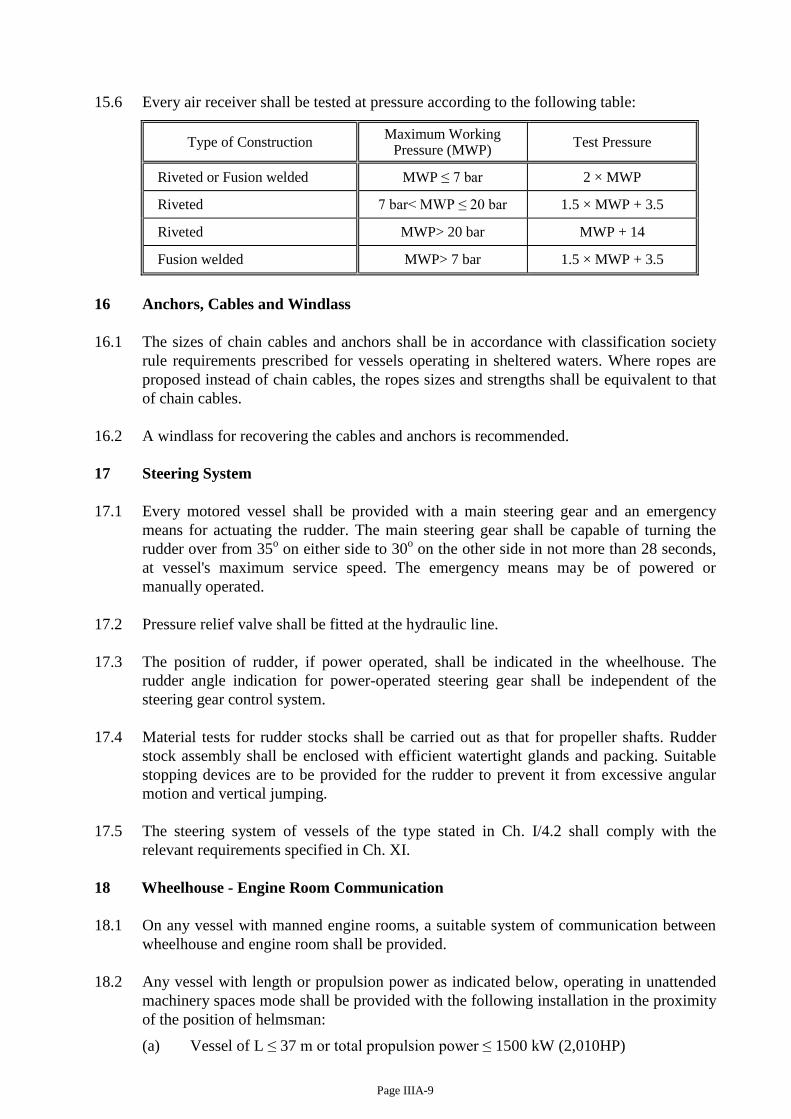
15.6 Every air receiver shall be tested at pressure according to the following table:
Type of Construction Maximum Working
Pressure (MWP) Test Pressure
Riveted or Fusion welded MWP ≤ 7 bar 2 × MWP
Riveted 7 bar< MWP ≤ 20 bar 1.5 × MWP + 3.5
Riveted MWP> 20 bar MWP + 14
Fusion welded MWP> 7 bar 1.5 × MWP + 3.5
16 Anchors, Cables and Windlass
16.1 The sizes of chain cables and anchors shall be in accordance with classification society
rule requirements prescribed for vessels operating in sheltered waters. Where ropes are
proposed instead of chain cables, the ropes sizes and strengths shall be equivalent to that
of chain cables.
16.2 A windlass for recovering the cables and anchors is recommended.
17 Steering System
17.1 Every motored vessel shall be provided with a main steering gear and an emergency
means for actuating the rudder. The main steering gear shall be capable of turning the
rudder over from 35o on either side to 30
o on the other side in not more than 28 seconds,
at vessel's maximum service speed. The emergency means may be of powered or
manually operated.
17.2 Pressure relief valve shall be fitted at the hydraulic line.
17.3 The position of rudder, if power operated, shall be indicated in the wheelhouse. The
rudder angle indication for power-operated steering gear shall be independent of the
steering gear control system.
17.4 Material tests for rudder stocks shall be carried out as that for propeller shafts. Rudder
stock assembly shall be enclosed with efficient watertight glands and packing. Suitable
stopping devices are to be provided for the rudder to prevent it from excessive angular
motion and vertical jumping.
17.5 The steering system of vessels of the type stated in Ch. I/4.2 shall comply with the
relevant requirements specified in Ch. XI.
18 Wheelhouse - Engine Room Communication
18.1 On any vessel with manned engine rooms, a suitable system of communication between
wheelhouse and engine room shall be provided.
18.2 Any vessel with length or propulsion power as indicated below, operating in unattended
machinery spaces mode shall be provided with the following installation in the proximity
of the position of helmsman:
(a) Vessel of L ≤ 37 m or total propulsion power ≤ 1500 kW (2,010HP)
Page IIIA-10
(i) for main engine-
(1) means of start, stop and control of speed
(2) control of gearbox or clutch
(3) lubricating oil pressure gauges
(4) < lubricating oil low pressure alarm>
(5) cooling water pressure gauges (if fitted on the engine)
(6) cooling water temperature gauges
(7) < cooling water high temperature alarm>
(8) exhaust temperature gauges (if fitted on the engine)
(9) a fixed fire detection (operated by fire detectors) and fire alarm
system for engine room
(ii) for generator engine-
means to stop
(iii) for bilge water in engine room-
high level audible alarm.
(b) Vessel with length L >37 m or total propulsion power> 1500 kW(2010HP) would
be specially considered.
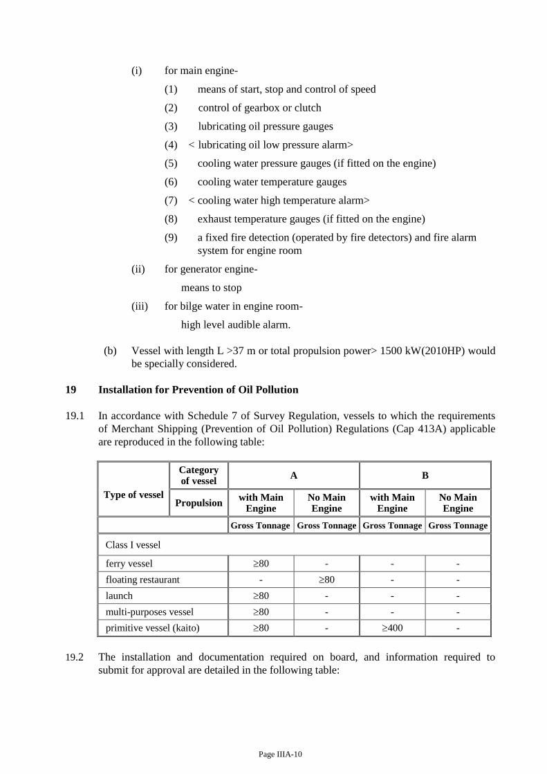
19 Installation for Prevention of Oil Pollution
19.1 In accordance with Schedule 7 of Survey Regulation, vessels to which the requirements
of Merchant Shipping (Prevention of Oil Pollution) Regulations (Cap 413A) applicable
are reproduced in the following table:
Type of vessel
Category of vessel
A B
Propulsion with Main
Engine No Main Engine
with Main Engine
No Main Engine
Gross Tonnage Gross Tonnage Gross Tonnage Gross Tonnage
Class I vessel
ferry vessel 80 - - -
floating restaurant - 80 - -
launch 80 - - -
multi-purposes vessel 80 - - -
primitive vessel (kaito) 80 - 400 -
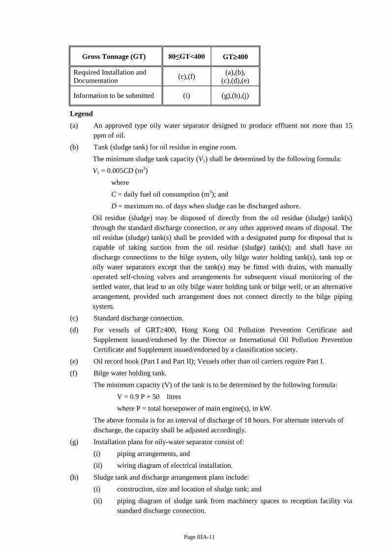
19.2 The installation and documentation required on board, and information required to
submit for approval are detailed in the following table:
Page IIIA-11
Gross Tonnage (GT) 80≤GT<400 GT400
Required Installation and
Documentation (c),(f)
(a),(b),
(c),(d),(e)
Information to be submitted (i) (g),(h),(j)
Legend
(a) An approved type oily water separator designed to produce effluent not more than 15
ppm of oil.
(b) Tank (sludge tank) for oil residue in engine room.
The minimum sludge tank capacity (V1) shall be determined by the following formula:
V1 = 0.005CD (m3)
where
C = daily fuel oil consumption (m3); and
D = maximum no. of days when sludge can be discharged ashore.
Oil residue (sludge) may be disposed of directly from the oil residue (sludge) tank(s)
through the standard discharge connection, or any other approved means of disposal. The
oil residue (sludge) tank(s) shall be provided with a designated pump for disposal that is
capable of taking suction from the oil residue (sludge) tank(s); and shall have no
discharge connections to the bilge system, oily bilge water holding tank(s), tank top or
oily water separators except that the tank(s) may be fitted with drains, with manually
operated self-closing valves and arrangements for subsequent visual monitoring of the
settled water, that lead to an oily bilge water holding tank or bilge well, or an alternative
arrangement, provided such arrangement does not connect directly to the bilge piping
system.
(c) Standard discharge connection.
(d) For vessels of GRT400, Hong Kong Oil Pollution Prevention Certificate and
Supplement issued/endorsed by the Director or International Oil Pollution Prevention
Certificate and Supplement issued/endorsed by a classification society.
(e) Oil record book (Part I and Part II); Vessels other than oil carriers require Part I.
(f) Bilge water holding tank.
The minimum capacity (V) of the tank is to be determined by the following formula:
V = 0.9 P + 50 litres
where P = total horsepower of main engine(s), in kW.
The above formula is for an interval of discharge of 18 hours. For alternate intervals of
discharge, the capacity shall be adjusted accordingly.
(g) Installation plans for oily-water separator consist of:
(i) piping arrangements, and
(ii) wiring diagram of electrical installation.
(h) Sludge tank and discharge arrangement plans include:
(i) construction, size and location of sludge tank; and
(ii) piping diagram of sludge tank from machinery spaces to reception facility via
standard discharge connection.
Page IIIA-12
(i) Bilge water holding tank and discharge arrangement plans include:
(i) construction, size and location of bilge holding tank; and
(ii) piping diagram of bilge water holding tank from machinery spaces to reception
facility via standard discharge connection.
(j) Shipboard oil pollution emergency plan (not required for sludge oil carriers).
19.3 Vessels shall maintain a valid certificate relevant to prevention of oil pollution as
required by Merchant Shipping (Prevention of Oil Pollution) Regulations (Cap 413 sub.
leg A) for the intended purpose of the vessel.
19.4 Provisions for discharge prohibition for oil pollution prevention as stipulated in Cap 313,
Cap 413 and Cap 548 must be complied with for all vessels, including those vessels not
mandatory required to provide with the physical arrangements/ equipment/document on
board as indicated in sections 19.1 and 19.2.
PART 4 ELECTRICAL INSTALLATION
20 Electrical Power Source
20.1 Nominal voltage of electrical system is recommended to be 380V for generation and
power circuits, 220V for lighting and distribution circuits and 24V D.C. for low voltage
circuits.
20.2 The hull return system shall not be used for power or lighting.
20.3 Where electrical power constitutes the only means of driving the lubrication oil pump and
cooling water pump for the main engine, a main source of electrical power shall be
provided which shall include at least two generating sets, one of which shall be driven by
internal combustion engine.
20.4 The vessel’s emergency lighting, navigation lights for vessels of length exceeding 24
metres, fixed fire extinguishing system, fire detection and alarm system and public
address system shall be provided with emergency power supply of sufficient capacity.
20.5 For vessels built on or after 29 November 2014 the emergency source of power shall not
be located below the full-load waterline of the vessel.
20.6 Ventilation fans serving machinery or cargo spaces, engines' oil fuel pumps and other
similar oil pumps shall be capable to be stopped outside of the space where the appliance
is situated.
20.7 Each navigation light shall be connected separately to the distribution board served for
this purpose.
<20.8 In every electric or electro-hydraulic power steering gear system on vessel:
(a) the steering gear shall have two independent sets of supply cables connecting
direct to main switchboard;
(b) the supply circuits of steering gear control system shall be provided with short
circuit protection only;
(c) the steering gear motors shall have an overload alarm instead of overload
protection. The short circuit protection shall be not less than twice the total rated
current of the motor in the circuit protected.
Page IIIA-13
This subsection is not applicable to vessels fitted with a separate power-operated means
of steering.>
21 Precautions against Shock, Fire and Other Hazards of Electrical Origin
21.1 (a) Exposed permanently fixed metal parts of electrical machines or equipment which
are not intended to be "live", but which are liable under fault conditions to
become "live" shall be earthed unless they are supplied at a voltage not exceeding
50 volts.
(b) Electrical apparatus shall be so constructed and so installed that it shall not cause
injury to person when handled or touched in the normal manner.
21.2 Main and emergency switchboards shall be so arranged as to give easy access as may be
needed to apparatus and equipment, without danger to attendants. The sides and backs
and, where necessary, the fronts of switchboards, shall be suitably guarded. Exposed
"live" parts having voltages exceeding 50 volts shall not be installed on the front of such
switchboards. There shall be non-conducting mats or gratings at the front and rear, where
necessary.
21.3 The distribution system if exceeds 50V, whether primary or secondary, for power or
lighting, with no connection to earth is used, a device capable of monitoring the
insulation level to earth shall be provided.
21.4 (a) The voltage rating of any cable shall not be less than the nominal voltage.
(b) Every conductor of a cable, flexible cable or flexible cord shall be capable of
carrying the maximum current which will normally flow through it without
exceeding the appropriate current rating as specified by manufacturer of the cable.
(c) Cable runs shall be selected so as to avoid action from condensed moisture or drip.
Cables shall, as far as possible, be remote from sources of heat, such as hot pipes,
resistors, etc.
(d) Cables shall be prevented from mechanical damage. When necessary cables shall
be enclosed in suitable conduits or casings, or armoured cables shall be used.
21.5 (a) Circuits shall be protected against short circuit and overload.
(b) The current rating of circuit breaker shall not exceed the current rating of the
smallest size of cable in the circuit protected by the circuit breaker.
21.6 Lighting fittings shall be arranged to prevent temperature rises which could damage the
wiring and to prevent surrounding material from becoming excessively hot.
21.7 In spaces where flammable gas mixtures are liable to collect and in any compartment
assigned principally to the containment of an accumulator battery, the electrical fittings
shall be of flameproof type.
21.8 (a) The housing of accumulator batteries shall be properly stowed in a locker which
shall be well ventilated.
(b) Accumulator batteries shall not be located in the crew or passenger spaces.
<21.9 A lightning conductor is recommended to be fitted for a vessel which hull or mast is
constructed of nonconductive materials. The lightning conductor might be connected to
a copper plate fixed to the vessel's hull well below the lightship waterline. >

Page IIIA-14
21.10 When any work to be carried out on electrical appliances a signboard showing “Work in
Progress” shall be displayed at prominent position of the electrical panel to prohibit
anyone from operating the panel.
Page IIIB-1
CHAPTER III B HULL CONSTRUCTION, MACHINERY, ELECTRICAL INSTALLATIONS
AND FITTINGS - CATEGORY B VESSEL
PART 1 GENERAL REQUIREMENTS
(1) Any replacement kaito carrying not more than 60 passengers shall be built in a shipyard having been certified competent for the construction by Marine Department or RA in the mainland, with regard to its facilities, organization and capability. A copy of the certification, if issued by the mainland authority, shall be furnished to Marine Department for consideration/record.
(2) Suitable means or device shall be provided to machinery, equipment, lifting gear and
winch, etc. so as to reduce to a minimum any danger to persons on board. Special attention shall be paid to moving parts, hot surfaces and other potential dangers.
PART 2 HULL CONSTRUCTION
1 Hull and Bulkheads
1.1 Any motor vessel shall be fitted with:
< (a) a collision bulkhead (for vessels of other than wooden vessels and of length (L) exceeding 8 m); >
(b) engine room fore bulkhead; and
(c) engine room aft bulkhead, unless the machinery space is situated at aft end of the vessel.
1.2 For vessels of other than wooden construction, the bulkheads shall be of watertight construction. Bulkheads in vessels of wooden construction shall be as far as practicable of watertight construction. Openings fitted on bulkhead for the passing of pipes, cables, etc. shall be accordingly constructed.
1.3 < Access opening fitted in a watertight bulkhead shall be equipped with effective watertight closing appliance. No opening is to be fitted in collision bulkhead on vessels other than wooden construction. >
2 Closing Appliances, Freeing Ports
2.1 The air pipes, ventilators, cargo hatchways, small hatchways, manholes and doors which are leading to a space below main deck shall be fitted with weathertight closing appliance and have a minimum coaming height of 230 or <300> mm on any vessel of other than wooden vessel.
2.2 No coaming is required for watertight manholes.
2.3 If bulwark is fitted at the shipside on vessels operating outside the Specified Sheltered Waters, freeing ports shall be provided in both sides of the bulwark with the minimum aggregate area (in m2) indicated in the following table. For vessels operating beyond Hong Kong Waters, the aggregate area shall be twice of that indicated in the tables.

Page IIIB-2
Length (L) (m) Aggregate Freeing Port Area (m2)
L ≦ 12 0.0115 L
12 < L < 24 (0.00146 L-0.006) L
L ≧ 24 0.029 L
3 Protection of Passengers and Crew
Ch.IIIA/4 refer. 4 Flooring
Ch.IIIA/5 refers. 5 Marking of Hull
For vessels of all kinds of construction, Ch.IIIA/6.1 refers. PART 3 MACHINERY INSTALLATION 6 Main Engine and Engine Fitting
The engine's exhaust pipe shall be lagged with heat-resistant material unless it is served by a water cooling system. A silencer or expansion chamber shall be fitted on the exhaust pipe. <Main engine crankcase shall be fitted with venting pipe leading to the open deck>.
7 Engine Room
7.1 Adequate ventilation shall be provided in engine room. If only natural ventilation is provided, at least two cowl ventilators of adequate size shall be fitted.
7.2 If the vessel is of wooden construction or GRP of non-oil resistant material, a metal tray, which can readily be cleaned, shall be fitted under the engine to protect the bilges against saturation by oil.
7.3 Every machinery spaces shall be at all times kept clean and free from unnecessary combustible materials and that waste oil is not allowed to accumulate in the bilges.
8 Nature of Fuel
Ch.IIIA/11 refers. 9 Tanks
9.1 The arrangements for filling fuel tanks are to be such that oil will not spill or overflow into any compartment of the vessel. Woodwork surrounding deck-filling mouth shall be covered with sheet metal. No loose can/barrel of fuel oil is to be carried on board.
9.2 Fuel tanks shall be substantially constructed of suitable material and securely fixed in position.
10 Pumping and Piping Arrangement
Ch.IIIA/13 refers.
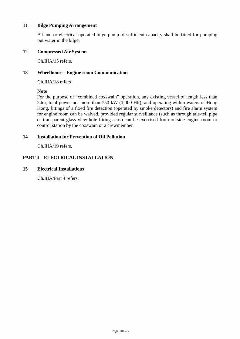
Page IIIB-3
11 Bilge Pumping Arrangement
A hand or electrical operated bilge pump of sufficient capacity shall be fitted for pumping out water in the bilge.
12 Compressed Air System
Ch.IIIA/15 refers. 13 Wheelhouse - Engine room Communication
Ch.IIIA/18 refers
Note For the purpose of “combined coxswain” operation, any existing vessel of length less than 24m, total power not more than 750 kW (1,000 HP), and operating within waters of Hong Kong, fittings of a fixed fire detection (operated by smoke detectors) and fire alarm system for engine room can be waived, provided regular surveillance (such as through tale-tell pipe or transparent glass view-hole fittings etc.) can be exercised from outside engine room or control station by the coxswain or a crewmember.
14 Installation for Prevention of Oil Pollution
Ch.IIIA/19 refers. PART 4 ELECTRICAL INSTALLATION 15 Electrical Installations
Ch.IIIA/Part 4 refers.
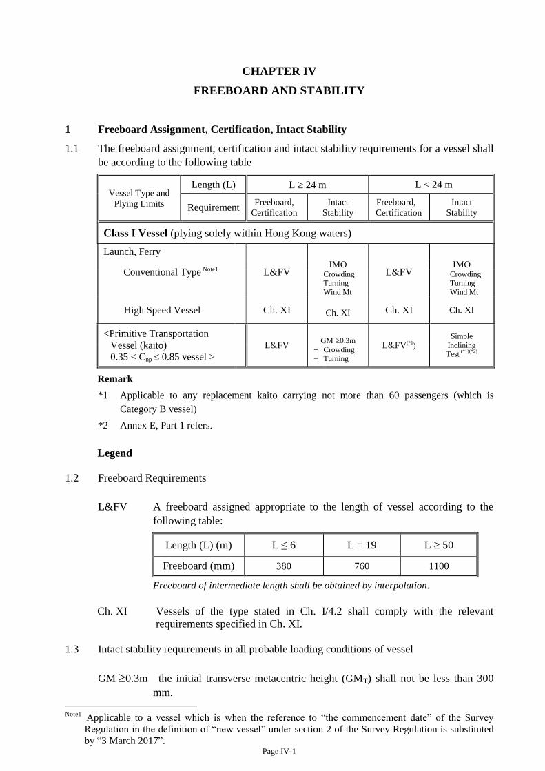
Page IV-1
CHAPTER IV
FREEBOARD AND STABILITY
1 Freeboard Assignment, Certification, Intact Stability
1.1 The freeboard assignment, certification and intact stability requirements for a vessel shall
be according to the following table
Vessel Type and Plying Limits
Length (L) L 24 m L < 24 m
Requirement Freeboard,
Certification
Intact
Stability
Freeboard,
Certification
Intact
Stability
Class I Vessel (plying solely within Hong Kong waters)
Launch, Ferry
Conventional Type Note1
L&FV
IMO L&FV
IMO
Crowding Turning Wind Mt
Crowding Turning Wind Mt
High Speed Vessel Ch. XI Ch. XI Ch. XI Ch. XI
<Primitive Transportation
Vessel (kaito)
0.35 < Cnp 0.85 vessel > L&FV
GM 0.3m L&FV(*1
) Simple
Inclining Test
(*1)(*2) +
+
Crowding Turning
Remark
*1 Applicable to any replacement kaito carrying not more than 60 passengers (which is
Category B vessel)
*2 Annex E, Part 1 refers.
Legend
1.2 Freeboard Requirements
L&FV A freeboard assigned appropriate to the length of vessel according to the
following table:
Length (L) (m) L ≤ 6 L = 19 L 50
Freeboard (mm) 380 760 1100
Freeboard of intermediate length shall be obtained by interpolation.
Ch. XI Vessels of the type stated in Ch. I/4.2 shall comply with the relevant
requirements specified in Ch. XI.
1.3 Intact stability requirements in all probable loading conditions of vessel
GM 0.3m the initial transverse metacentric height (GMT) shall not be less than 300
mm. Note1
Applicable to a vessel which is when the reference to “the commencement date” of the Survey
Regulation in the definition of “new vessel” under section 2 of the Survey Regulation is substituted
by “3 March 2017”.
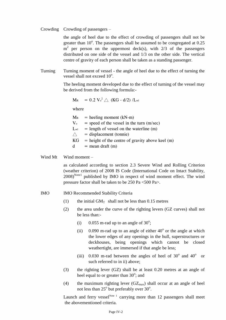
Page IV-2
Crowding Crowding of passengers –
the angle of heel due to the effect of crowding of passengers shall not be
greater than 10o. The passengers shall be assumed to be congregated at 0.25
m2 per person on the uppermost deck(s), with 2/3 of the passengers
distributed on one side of the vessel and 1/3 on the other side. The vertical
centre of gravity of each person shall be taken as a standing passenger.
Turning Turning moment of vessel - the angle of heel due to the effect of turning the
vessel shall not exceed 10o.
The heeling moment developed due to the effect of turning of the vessel may
be derived from the following formula:-
MR = 0.2 Vo2 △ (KG - d/2) /Lwl
where
MR = heeling moment (kN-m)
Vo = speed of the vessel in the turn (m/sec)
Lwl = length of vessel on the waterline (m)
△ = displacement (tonnie)
KG = height of the centre of gravity above keel (m)
d = mean draft (m)
Wind Mt Wind moment –
as calculated according to section 2.3 Severe Wind and Rolling Criterion
(weather criterion) of 2008 IS Code (International Code on Intact Stability,
2008)Note1
published by IMO in respect of wind moment effect. The wind
pressure factor shall be taken to be 250 Pa <500 Pa>.
IMO IMO Recommended Stability Criteria
(1) the initial GMT shall not be less than 0.15 metres
(2) the area under the curve of the righting levers (GZ curves) shall not
be less than:-
(i) 0.055 m-rad up to an angle of 30o;
(ii) 0.090 m-rad up to an angle of either 40o or the angle at which
the lower edges of any openings in the hull, superstructures or
deckhouses, being openings which cannot be closed
weathertight, are immersed if that angle be less;
(iii) 0.030 m-rad between the angles of heel of 30o and 40
o or
such referred to in ii) above;
(3) the righting lever (GZ) shall be at least 0.20 metres at an angle of
heel equal to or greater than 30o; and
(4) the maximum righting lever (GZmax) shall occur at an angle of heel
not less than 25o but preferably over 30
o.
Launch and ferry vesselNote 1 carrying more than 12 passengers shall meet
the abovementioned criteria.

Page IV-3
Vessels of the type stated in Ch. I/4.2 shall comply with the relevant
requirements specified in Chapter XI.
1.4 Determination of minimum freeboard
A vessel shall meet the relevant stability criteria for the draught corresponding to the
freeboard assigned.
1.5 Equivalent freeboard and stability criteria
1.5.1 Where it is not practical for any particular vessel, due to its geometric characteristics (e.g.
the ratio of beam / depth is exceeding 2.5) or operating condition, to fully comply with
the stipulated freeboard or stability criteria, the Department may permit the application of
equivalent criteria which are at least as effective as that so specified.
1.5.2 For vessels of L<20m carrying ≤100 passengers, the Department accepts the standard
applicable to vessels operating within sheltered waters, as stipulated in the Technical
Regulation for the Survey of Coastal Boats promulgated by Maritime Safety
Administration of the People’s Republic of China (MSA); or the equivalent. For vessels
of L≥20m carrying ≤100passengers, the Department accepts the standard appropriate for
vessels operating in Hong Kong waters, as promulgated by the MSA.
2 Damage Stability
2.1 Every -
(a) launch and ferry vesselNote 1 carrying more than 12 passengers;
(b) replacement kaito Note 1carrying not more than 60 passengers
shall meet a damaged stability standard as prescribed in Annex F of this Code.
2.2 Vessels of the type stated in Ch. I/4.2 shall comply with the relevant requirements
specified in Chapter XI.
3 Inclining Test
3.1 With the exception of a vessel which stability is to be determined by a rolling period test,
every vessel which stability information is required as stated in section 1 shall be inclined
to confirm the vessel's displacement, vertical centre of gravity (VCG) and longitudinal
centre of gravity (LCG) in lightship condition when on completion or close to completion
of construction (new vessels) or modification (existing vessels). Inclining test report shall
be submitted for approval.
3.2 Dispensation with conducting an inclining test may be given to -
(a) a vessel being similar in all respects to the sister ship for which a satisfactory
inclining experiment report is available; and having been carried out a
lightweight survey (see section 4 below) the result of which indicates that the
deviations from –
(i) lightship displacement is not exceeding 2% for ships of L≤50 m; 1% for
ships of L>160 m (for intermediate L, by linear interpolation), and
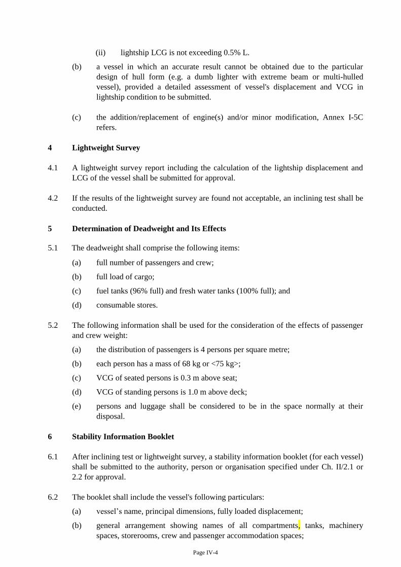
Page IV-4
(ii) lightship LCG is not exceeding 0.5% L.
(b) a vessel in which an accurate result cannot be obtained due to the particular
design of hull form (e.g. a dumb lighter with extreme beam or multi-hulled
vessel), provided a detailed assessment of vessel's displacement and VCG in
lightship condition to be submitted.
(c) the addition/replacement of engine(s) and/or minor modification, Annex I-5C
refers.
4 Lightweight Survey
4.1 A lightweight survey report including the calculation of the lightship displacement and
LCG of the vessel shall be submitted for approval.
4.2 If the results of the lightweight survey are found not acceptable, an inclining test shall be
conducted.
5 Determination of Deadweight and Its Effects
5.1 The deadweight shall comprise the following items:
(a) full number of passengers and crew;
(b) full load of cargo;
(c) fuel tanks (96% full) and fresh water tanks (100% full); and
(d) consumable stores.
5.2 The following information shall be used for the consideration of the effects of passenger
and crew weight:
(a) the distribution of passengers is 4 persons per square metre;
(b) each person has a mass of 68 kg or <75 kg>;
(c) VCG of seated persons is 0.3 m above seat;
(d) VCG of standing persons is 1.0 m above deck;
(e) persons and luggage shall be considered to be in the space normally at their
disposal.
6 Stability Information Booklet
6.1 After inclining test or lightweight survey, a stability information booklet (for each vessel)
shall be submitted to the authority, person or organisation specified under Ch. II/2.1 or
2.2 for approval.
6.2 The booklet shall include the vessel's following particulars:
(a) vessel’s name, principal dimensions, fully loaded displacement;
(b) general arrangement showing names of all compartments, tanks, machinery
spaces, storerooms, crew and passenger accommodation spaces;
Page IV-5
(c) the capacity and the VCG and LCG of every compartment available for the
carriage of cargo, fuel, water, water ballast, etc.;
(d) the effect on stability of free surface in each tank in which liquids may be carried;
(e) the estimated total weight of (i) passengers and their effects and (ii) crew and their
effects, and the VCG and LCG of each such total weight. In assessing such
centres of gravity passengers and crew shall be assumed to be distributed about
the ship in the spaces they will normally occupy, including the highest decks to
which either or both have access.
(f) the estimated weight and the disposition and centre of gravity of deck cargo;
(g) hydrostatic particulars, cross curves particulars;
(h) calculation of loading and righting levers (GZ) curves of -
(i) light condition,
(ii) fully loaded (to the assigned freeboard) condition,
(iii) service loaded conditions,
(iv) probable worst conditions.
Conditions (ii)~(iv) shall be calculated on both departure and arrival condition.
6.3 The approved stability booklet shall be placed on board the vessel for the reference of the
coxswain.
7 Permanent Ballast
When ballast is required to improve stability of the vessel, the correct quantity of ballast
shall at all times be fixed (or so stowed as not allowing movable when at sea) at the
specified position. Such quantity and position of permanent ballast shall be endorsed in
the Certificate of Survey.
8 Modification onboard
8.1 Before a vessel is to undergo any modification, application shall be submitted specifying
the nature of the proposed modification. Estimates of the effects of the modification, i.e.
the changes in vessel’s lightship weight, VCG and LCG shall be submitted to the Marine
Department for approval.
8.2 If the change due to modification, or the finding of lightweight survey is exceeding 2%,
an inclining test is to be conducted. The vessel’s intact stability information, and damage
stability information if applicable, shall be revised and submitted for approval.
8.3 No vessel is allowed to construct or alter to have false bottom or secret compartment.

Page F-1
Annex F
DAMAGED STABILITY REQUIREMENTS for LAUNCHES, FERRY VESSELS
PART 1 Damaged Stability Requirements
(1) (a) Every vessel to which sub-section (1)(b) or (c) applies shall be subdivided by bulkheads, which shall be watertight up to the bulkhead deck, into compartments the maximum length of which shall not exceed the length permitted by the required freeboard and stability as calculated in accordance with parts 2 and 3 of this Annex.
(b) Every vessel shall comply with the following subdivision standard:
No. of Passengers Carried Subdivision Standard
(Refer to para. (6) for the assumed extent and character of damage)
≤ 400 Any one main compartment
> 400 Note1 Any two adjacent main compartments
(c) Any launch or ferry vessel which meets the conditions required in Ch. V/3.3 and plies outside the Victoria port, shall meet the requirement of damage stability for two-compartment flooding.
(2) Every vessel shall be so constructed as to keep asymmetrical flooding, when the vessel
is in a damaged condition, at the minimum consistent with efficient arrangements. PART 2 Assumptions on which calculations are to be based The stability of every vessel shall be determined by calculation in accordance with the following conditions and assumptions-
(3) Applicable vessel size and arrangement:
(a) no passenger is carried underdeck;
(b) the vessel is fitted with plane bulkheads and no stepped bulkhead between main compartment is fitted;
(c) no partial subdivision above margin line is provided; and
(d) no cross-flooding fitting is provided.
(4) The vessel shall be assumed to be in the worst service conditions as regards stability which is likely to be experienced having regard to the intended service of the vessel, or damage calculations shall be made over the operational draught range as a basis for curves of required metacentric height (GM) values or permissible vertical centre of gravity (KG) values.
Note1 Applicable to any vessel which is when the reference to “the commencement date of the Survey
Regulation” in the definition of “new vessel” under section 2 of the Survey Regulation is substituted by “3 March 2017”.
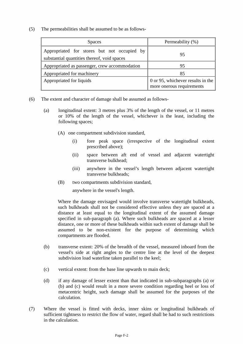
Page F-2
(5) The permeabilities shall be assumed to be as follows-
Spaces Permeability (%)
Appropriated for stores but not occupied by substantial quantities thereof, void spaces
95
Appropriated as passenger, crew accommodation 95 Appropriated for machinery 85 Appropriated for liquids
0 or 95, whichever results in the more onerous requirements
(6) The extent and character of damage shall be assumed as follows-
(a) longitudinal extent: 3 metres plus 3% of the length of the vessel, or 11 metres or 10% of the length of the vessel, whichever is the least, including the following spaces;
(A) one compartment subdivision standard,
(i) fore peak space (irrespective of the longitudinal extent prescribed above);
(ii) space between aft end of vessel and adjacent watertight transverse bulkhead;
(iii) anywhere in the vessel’s length between adjacent watertight transverse bulkheads;
(B) two compartments subdivision standard,
anywhere in the vessel's length.
Where the damage envisaged would involve transverse watertight bulkheads, such bulkheads shall not be considered effective unless they are spaced at a distance at least equal to the longitudinal extent of the assumed damage specified in sub-paragraph (a). Where such bulkheads are spaced at a lesser distance, one or more of these bulkheads within such extent of damage shall be assumed to be non-existent for the purpose of determining which compartments are flooded.
(b) transverse extent: 20% of the breadth of the vessel, measured inboard from the
vessel's side at right angles to the centre line at the level of the deepest subdivision load waterline taken parallel to the keel;
(c) vertical extent: from the base line upwards to main deck; (d) if any damage of lesser extent than that indicated in sub-subparagraphs (a) or
(b) and (c) would result in a more severe condition regarding heel or loss of metacentric height, such damage shall be assumed for the purposes of the calculation.
(7) Where the vessel is fitted with decks, inner skins or longitudinal bulkheads of
sufficient tightness to restrict the flow of water, regard shall be had to such restrictions in the calculation.
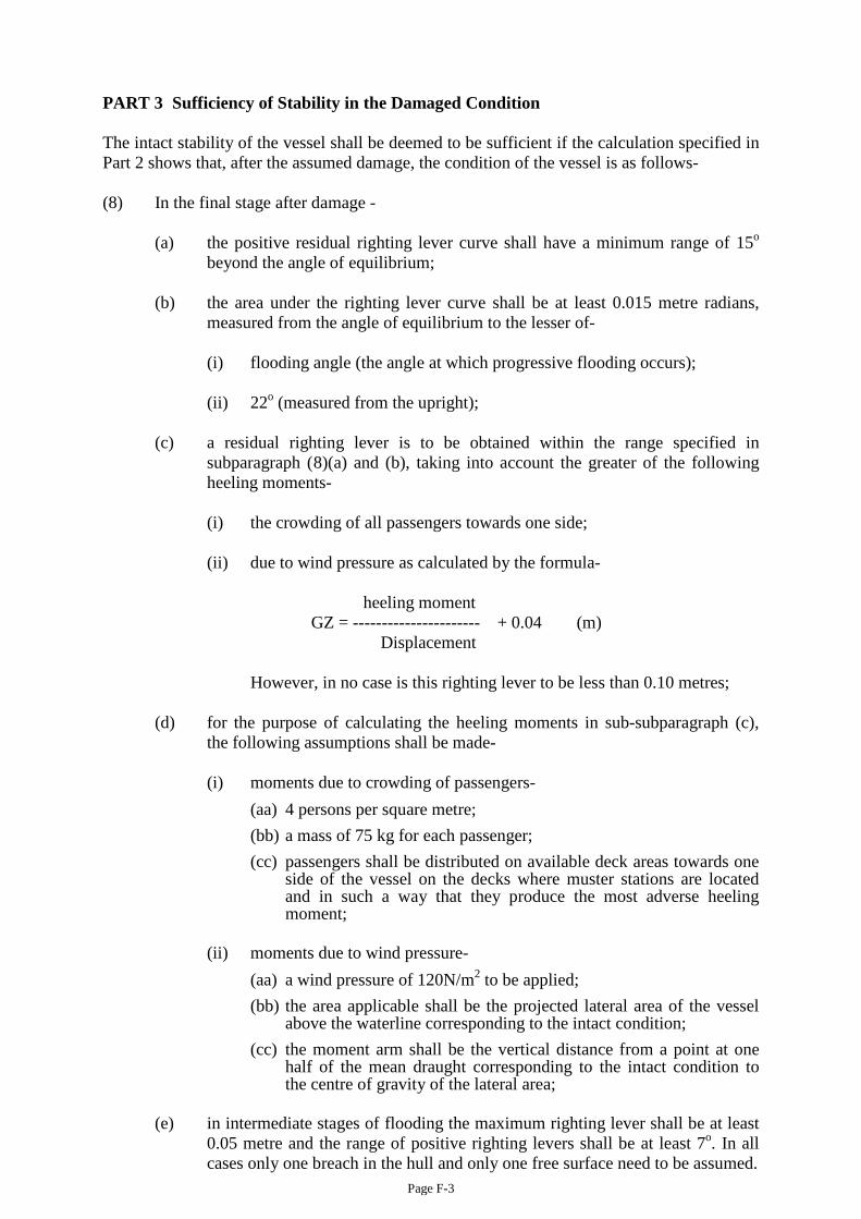
Page F-3
PART 3 Sufficiency of Stability in the Damaged Condition The intact stability of the vessel shall be deemed to be sufficient if the calculation specified in Part 2 shows that, after the assumed damage, the condition of the vessel is as follows- (8) In the final stage after damage -
(a) the positive residual righting lever curve shall have a minimum range of 15o
beyond the angle of equilibrium; (b) the area under the righting lever curve shall be at least 0.015 metre radians,
measured from the angle of equilibrium to the lesser of-
(i) flooding angle (the angle at which progressive flooding occurs); (ii) 22o (measured from the upright);
(c) a residual righting lever is to be obtained within the range specified in subparagraph (8)(a) and (b), taking into account the greater of the following heeling moments-
(i) the crowding of all passengers towards one side; (ii) due to wind pressure as calculated by the formula-
heeling moment GZ = ---------------------- + 0.04 (m) Displacement
However, in no case is this righting lever to be less than 0.10 metres; (d) for the purpose of calculating the heeling moments in sub-subparagraph (c),
the following assumptions shall be made-
(i) moments due to crowding of passengers- (aa) 4 persons per square metre; (bb) a mass of 75 kg for each passenger; (cc) passengers shall be distributed on available deck areas towards one
side of the vessel on the decks where muster stations are located and in such a way that they produce the most adverse heeling moment;
(ii) moments due to wind pressure-
(aa) a wind pressure of 120N/m2 to be applied; (bb) the area applicable shall be the projected lateral area of the vessel
above the waterline corresponding to the intact condition; (cc) the moment arm shall be the vertical distance from a point at one
half of the mean draught corresponding to the intact condition to the centre of gravity of the lateral area;
(e) in intermediate stages of flooding the maximum righting lever shall be at least
0.05 metre and the range of positive righting levers shall be at least 7o. In all cases only one breach in the hull and only one free surface need to be assumed.
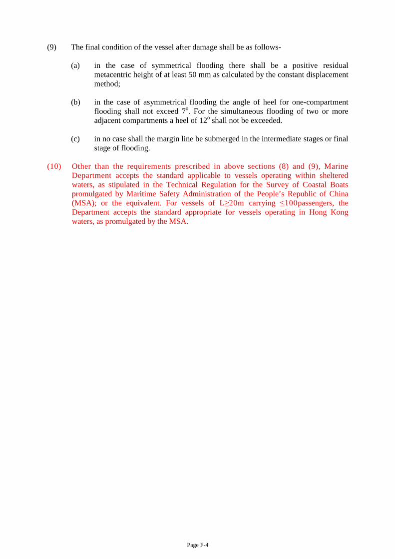
Page F-4
(9) The final condition of the vessel after damage shall be as follows-
(a) in the case of symmetrical flooding there shall be a positive residual metacentric height of at least 50 mm as calculated by the constant displacement method;
(b) in the case of asymmetrical flooding the angle of heel for one-compartment
flooding shall not exceed 7o. For the simultaneous flooding of two or more adjacent compartments a heel of 12o shall not be exceeded.
(c) in no case shall the margin line be submerged in the intermediate stages or final
stage of flooding.
(10) Other than the requirements prescribed in above sections (8) and (9), Marine Department accepts the standard applicable to vessels operating within sheltered waters, as stipulated in the Technical Regulation for the Survey of Coastal Boats promulgated by Maritime Safety Administration of the People’s Republic of China (MSA); or the equivalent. For vessels of L≥20m carrying ≤100passengers, the Department accepts the standard appropriate for vessels operating in Hong Kong waters, as promulgated by the MSA.

CODE OF PRACTICE ----
Safety Standards for Class II Vessels
(issued under Section 8 of the Merchant Shipping (Local Vessels) Ordinance, Cap 548) Local Vessels Safety Section Marine Department, HKSAR (June 2017 Edition)
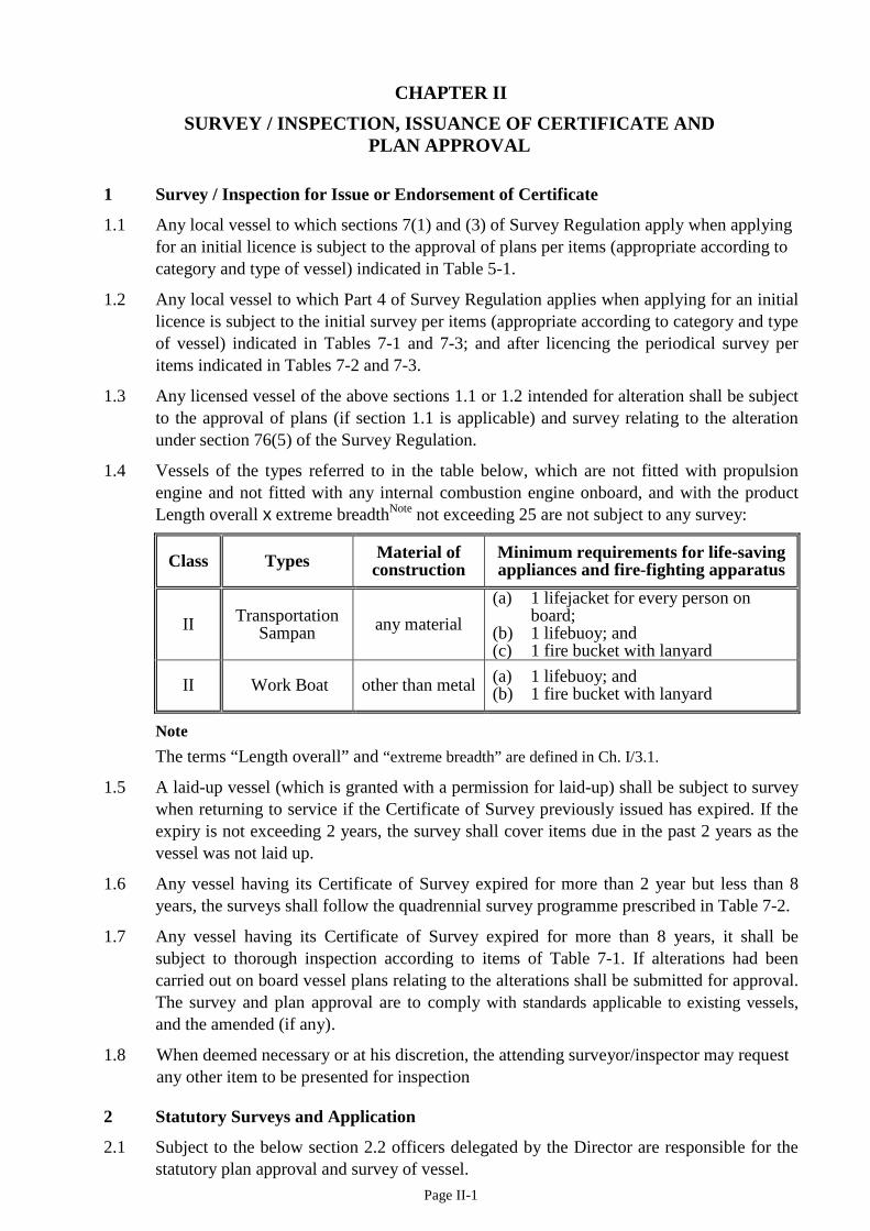
Page II-1
CHAPTER II SURVEY / INSPECTION, ISSUANCE OF CERTIFICATE AND
PLAN APPROVAL
1 Survey / Inspection for Issue or Endorsement of Certificate
1.1 Any local vessel to which sections 7(1) and (3) of Survey Regulation apply when applying for an initial licence is subject to the approval of plans per items (appropriate according to category and type of vessel) indicated in Table 5-1.
1.2 Any local vessel to which Part 4 of Survey Regulation applies when applying for an initial licence is subject to the initial survey per items (appropriate according to category and type of vessel) indicated in Tables 7-1 and 7-3; and after licencing the periodical survey per items indicated in Tables 7-2 and 7-3.
1.3 Any licensed vessel of the above sections 1.1 or 1.2 intended for alteration shall be subject to the approval of plans (if section 1.1 is applicable) and survey relating to the alteration under section 76(5) of the Survey Regulation.
1.4 Vessels of the types referred to in the table below, which are not fitted with propulsion engine and not fitted with any internal combustion engine onboard, and with the product Length overall x extreme breadthNote not exceeding 25 are not subject to any survey:
Class Types Material of construction
Minimum requirements for life-saving appliances and fire-fighting apparatus
II Transportation Sampan any material
(a) 1 lifejacket for every person on board;
(b) 1 lifebuoy; and (c) 1 fire bucket with lanyard
II Work Boat other than metal (a) 1 lifebuoy; and (b) 1 fire bucket with lanyard
Note The terms “Length overall” and “extreme breadth” are defined in Ch. I/3.1.
1.5 A laid-up vessel (which is granted with a permission for laid-up) shall be subject to survey when returning to service if the Certificate of Survey previously issued has expired. If the expiry is not exceeding 2 years, the survey shall cover items due in the past 2 years as the vessel was not laid up.
1.6 Any vessel having its Certificate of Survey expired for more than 2 year but less than 8 years, the surveys shall follow the quadrennial survey programme prescribed in Table 7-2.
1.7 Any vessel having its Certificate of Survey expired for more than 8 years, it shall be subject to thorough inspection according to items of Table 7-1. If alterations had been carried out on board vessel plans relating to the alterations shall be submitted for approval. The survey and plan approval are to comply with standards applicable to existing vessels, and the amended (if any).
1.8 When deemed necessary or at his discretion, the attending surveyor/inspector may request any other item to be presented for inspection
2 Statutory Surveys and Application
2.1 Subject to the below section 2.2 officers delegated by the Director are responsible for the statutory plan approval and survey of vessel.
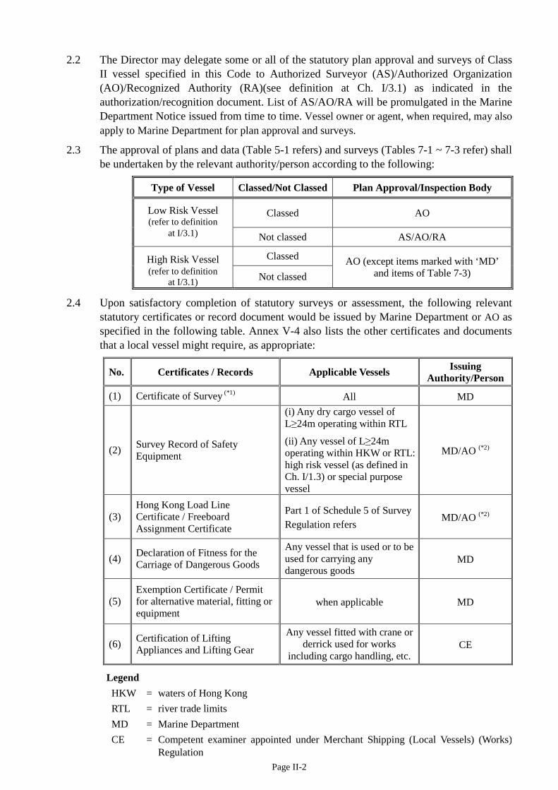
Page II-2
2.2 The Director may delegate some or all of the statutory plan approval and surveys of Class II vessel specified in this Code to Authorized Surveyor (AS)/Authorized Organization (AO)/Recognized Authority (RA)(see definition at Ch. I/3.1) as indicated in the authorization/recognition document. List of AS/AO/RA will be promulgated in the Marine Department Notice issued from time to time. Vessel owner or agent, when required, may also apply to Marine Department for plan approval and surveys.
2.3 The approval of plans and data (Table 5-1 refers) and surveys (Tables 7-1 ~ 7-3 refer) shall be undertaken by the relevant authority/person according to the following:
Type of Vessel Classed/Not Classed Plan Approval/Inspection Body
Low Risk Vessel (refer to definition
Classed AO
at I/3.1) Not classed AS/AO/RA
High Risk Vessel Classed AO (except items marked with ‘MD’ and items of Table 7-3) (refer to definition
at I/3.1) Not classed
2.4 Upon satisfactory completion of statutory surveys or assessment, the following relevant statutory certificates or record document would be issued by Marine Department or AO as specified in the following table. Annex V-4 also lists the other certificates and documents that a local vessel might require, as appropriate:
No. Certificates / Records Applicable Vessels Issuing Authority/Person
(1) Certificate of Survey (*1) All MD
(2) Survey Record of Safety Equipment
(i) Any dry cargo vessel of L≥24m operating within RTL
(ii) Any vessel of L≥24m operating within HKW or RTL: high risk vessel (as defined in Ch. I/1.3) or special purpose vessel
MD/AO (*2)
(3) Hong Kong Load Line Certificate / Freeboard Assignment Certificate
Part 1 of Schedule 5 of Survey Regulation refers
MD/AO (*2)
(4) Declaration of Fitness for the Carriage of Dangerous Goods
Any vessel that is used or to be used for carrying any dangerous goods
MD
(5) Exemption Certificate / Permit for alternative material, fitting or equipment
when applicable MD
(6) Certification of Lifting Appliances and Lifting Gear
Any vessel fitted with crane or derrick used for works
including cargo handling, etc. CE
Legend HKW = waters of Hong Kong RTL = river trade limits MD = Marine Department CE = Competent examiner appointed under Merchant Shipping (Local Vessels) (Works)
Regulation
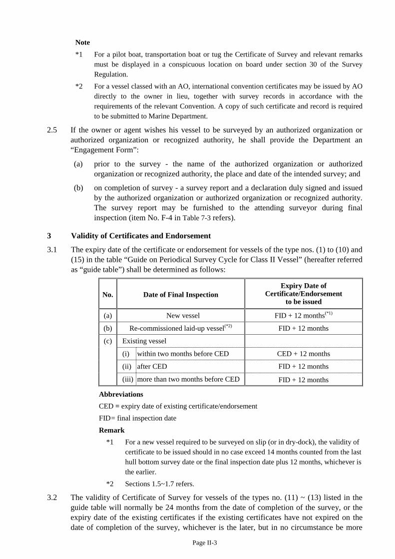
Page II-3
Note *1 For a pilot boat, transportation boat or tug the Certificate of Survey and relevant remarks
must be displayed in a conspicuous location on board under section 30 of the Survey Regulation.
*2 For a vessel classed with an AO, international convention certificates may be issued by AO directly to the owner in lieu, together with survey records in accordance with the requirements of the relevant Convention. A copy of such certificate and record is required to be submitted to Marine Department.
2.5 If the owner or agent wishes his vessel to be surveyed by an authorized organization or authorized organization or recognized authority, he shall provide the Department an “Engagement Form”:
(a) prior to the survey - the name of the authorized organization or authorized organization or recognized authority, the place and date of the intended survey; and
(b) on completion of survey - a survey report and a declaration duly signed and issued by the authorized organization or authorized organization or recognized authority. The survey report may be furnished to the attending surveyor during final inspection (item No. F-4 in Table 7-3 refers).
3 Validity of Certificates and Endorsement
3.1 The expiry date of the certificate or endorsement for vessels of the type nos. (1) to (10) and (15) in the table “Guide on Periodical Survey Cycle for Class II Vessel” (hereafter referred as “guide table”) shall be determined as follows:
No. Date of Final Inspection Expiry Date of
Certificate/Endorsement to be issued
(a) New vessel FID + 12 months(*1)
(b) Re-commissioned laid-up vessel(*2) FID + 12 months
(c) Existing vessel
(i) within two months before CED CED + 12 months
(ii) after CED FID + 12 months
(iii) more than two months before CED FID + 12 months
Abbreviations CED = expiry date of existing certificate/endorsement FID = final inspection date
Remark *1 For a new vessel required to be surveyed on slip (or in dry-dock), the validity of
certificate to be issued should in no case exceed 14 months counted from the last hull bottom survey date or the final inspection date plus 12 months, whichever is the earlier.
*2 Sections 1.5~1.7 refers.
3.2 The validity of Certificate of Survey for vessels of the types no. (11) ~ (13) listed in the guide table will normally be 24 months from the date of completion of the survey, or the expiry date of the existing certificates if the existing certificates have not expired on the date of completion of the survey, whichever is the later, but in no circumstance be more
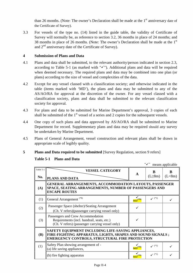
Page II-4
than 26 months. (Note: The owner’s Declaration shall be made at the 1st anniversary date of the Certificate of Survey).
3.3 For vessels of the type no. (14) listed in the guide table, the validity of Certificate of Survey will normally be, as reference to section 3.2, 36 months in place of 24 months; and 38 months in place of 26 months. (Note: The owner’s Declaration shall be made at the 1st and 2nd anniversary date of the Certificate of Survey).
4 Submission of Plans and Data
4.1 Plans and data shall be submitted, to the relevant authority/person indicated in section 2.3, according to Table 5-1 (as marked with ""). Additional plans and data will be required when deemed necessary. The required plans and data may be combined into one plan (or plans) according to the size of vessel and complexities of the data.
4.2 Except for any vessel classed with a classification society; and otherwise indicated in the table (items marked with ‘MD’), the plans and data may be submitted to any of the AS/AO/RA for approval at the discretion of the owner. For any vessel classed with a classification society, plans and data shall be submitted to the relevant classification society for approval.
4.3 For plans and data to be submitted for Marine Department’s approval, 3 copies of each shall be submitted of the 1st vessel of a series and 2 copies for the subsequent vessels.
4.4 One copy of such plans and data approved by AS/AO/RA shall be submitted to Marine Department for record. Supplementary plans and data may be required should any survey be undertaken by Marine Department.
4.5 Plans of General Arrangement, vessel construction and relevant plans shall be drawn in appropriate scale of legibly quality.
5 Plans and Data required to be submitted [Survey Regulation, section 9 refers]
Table 5-1 Plans and Data “”means applicable
Table 5-1 VESSEL CATEGORY PLANS AND DATA
A B (L≥8m)
B (L<8m) No.
(A) GENERAL ARRANGEMENTS, ACCOMMODATION LAYOUTS, PASSENGER SPACE, SEATING ARRANGEMENTS, NUMBER OF PASSENGERS AND ESCAPE ROUTES
(1) General Arrangement (*8)
MD(*9) (*1)
(2) Passenger Space (shelter)/Seating Arrangement (Ch. V refers)(passenger carrying vessel only)
(3) Passengers and Crew Accommodation
Requirements (incl. handrail, seats, etc.) (Ch. V refers) (passenger carrying vessel only)
(B) SAFETY EQUIPMENT INCLUDING LIFE-SAVING APPLIANCES, FIRE-FIGHTING APPARATUS, LIGHTS, SHAPES AND SOUND SIGNALS ; EMERGENCY CONTROLS, STRUCTURAL FIRE PROTECTION
(1) Safety Plan showing arrangement of - (a) life saving appliances,
MD(*9) (*1)
(b) fire fighting apparatus
MD(*9) (*1)
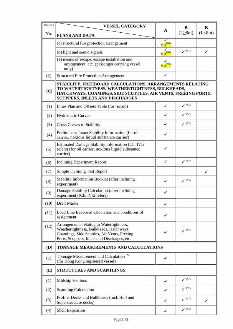
Page II-5
Table 5-1 VESSEL CATEGORY PLANS AND DATA
A B (L≥8m)
B (L<8m) No.
(c) structural fire protection arrangement
MD(*9)
(d) light and sound signals
MD(*9) (*1)
(e) means of escape, escape installation and
arrangement, etc. (passenger carrying vessel only)
MD(*9)
(2) Structural Fire Protection Arrangement
(C) STABILITY, FREEBOARD CALCULATIONS, ARRANGEMENTS RELATING TO WATERTIGHTNESS, WEATHERTIGHTNESS, BULKHEADS, HATCHWAYS, COAMINGS, SIDE SCUTTLES, AIR VENTS, FREEING PORTS, SCUPPERS, INLETS AND DISCHARGES
(1) Lines Plan and Offsets Table (for record) (*2)
(2) Hydrostatic Curves (*2)
(3) Cross Curves of Stability (*2)
(4) Preliminary Intact Stability Information (for oil carrier, noxious liquid substance carrier)
(5) Estimated Damage Stability Information (Ch. IV/2 refers) (for oil carrier, noxious liquid substance carrier)
(6) Inclining Experiment Report (*3)
(7) Simple Inclining Test Report
(8) Stability Information Booklet (after inclining experiment) (*3)
(9) Damage Stability Calculation (after inclining experiment) (Ch. IV/2 refers)
(10) Draft Marks
(11) Load Line freeboard calculation and conditions of assignment
(12) Arrangements relating to Watertightness, Weathertightness, Bulkheads, Hatchways, Coamings, Side Scuttles, Air Vents, Freeing Ports, Scuppers, Inlets and Discharges, etc.
(*2)
(D) TONNAGE MEASUREMENTS AND CALCULATIONS
(1) Tonnage Measurement and Calculation (*4) (for Hong Kong registered vessel)
(E) STRUCTURES AND SCANTLINGS
(1) Midship Sections (*2)
(2) Scantling Calculation (*2)
(3) Profile, Decks and Bulkheads (incl. Hull and Superstructure decks)
(*2)
(4) Shell Expansion (*2)

Page II-6
Table 5-1 VESSEL CATEGORY PLANS AND DATA
A B (L≥8m)
B (L<8m) No.
(5) Rudder/Kort Nozzle, Rudder Stock, Skeg and Sole Piece
(*2)
(6) Mooring Arrangement and Equipment Number Calculation (for oil carrier , DG carriers and L>75m dumb steel lighters)
(F) FUEL, MACHINERY, SHAFTING
(1) Engine Room Arrangement
(2) Pump Room Arrangement (for oil carrier)
(3) Propeller Shafting, Stern Tube and Coupling
(4) Main Engine and Gear Box Certificates (*5)
(5) Aux. Diesel Engine Certificates (*5)
(6) Fuel Oil System (incl. tanks, piping)
(7) Fire-fighting Piping Arrangement (incl. fire main, fixed fire extinguishing system,etc)
(8) Bilge Pumping Arrangement
(9) Compressed Air Piping System (for pressure ≥ 10 bar)
(10) Air Receiver (Ch. IIIA/15 refers)
(11) Steering Gear Hydraulic Piping System
(12) Fresh Water System (incl. tank construction, piping) (for water boat)
(13) Cargo Tank Venting System (for oil carrier)
(14) Filling, Sounding and Air Vent System (*6)
(G) ELECTRICAL SYSTEMS (including Emergency Power System)
(1) Electrical System Line diagram (*7)
(2) Wiring Diagram of Main Switchboard (*7)
(3) Layout of Main Switchboard (*7)
(4) Electrical Arrangement (*7)
(5) Wiring Diagram of Distribution Boxes (*7)
(H) PREVENTION AND CONTROL OF POLLUTION
(1) Prevention of Oil Pollution Installation (Ch. IIIA/19.2 refers)
MD/AO MD/AO
(2) Prevention of Air Pollution Installation (Annex I-10 refers) MD/AO MD/AO
(I) NAVIGATIONAL AND COMMUNICATION EQUIPMENT

Page II-7
Table 5-1 VESSEL CATEGORY PLANS AND DATA
A B (L≥8m)
B (L<8m) No.
(1) Radio Communication equipment and arrangement
(2) Navigational equipment and arrangement
(3) Visibility Calculation (for oil carriers)
(J) MEASURES AGAINST POTENTIAL HAZARDS TO THE SAFETY OF THE VESSEL AND ANY PERSON OR PROPERTY ON BOARD THE VESSEL
(1) Supplementary information/data and list of inspection, testing & trial requirements relating to the type of vessel
(2) Additional Items for Oil Carriers having cargoes ≤ 60oC (Ch.VI refers)
(3) Additional Items for DG or NLS Carrier (Ch.VI refers)
(4) Domestic LPG Installation (Annex U-1 refers)
(K) LIFTING APPLIANCES (including derrick cranes, extensible jib cranes and fixed-jib crane etc.)
(1) Strength calculations for the stress members (*9)
(2) Rigging diagrams Competent Examiner (*10) (*11)
(3) As fitted drawings
Remarks in Table 5-1 *1 Applicable to the following Category B vessels: dumb lighter, hopper barge, water boat, flat
top work barge, landing pontoon, stationary vessel. *2 Applicable to dumb lighter and hopper barge. *3 For any dumb lighter required to be submitted with heavy lifting stability calculations and
hopper barge. *4 International Tonnage Certificate issued by an administration (or classification society on
her behalf) may be acceptable to Marine Department. *5 For new vessels, engine maker or classification societies approved certificates / information
and document as appropriate required in Ch. IIIA or IIIB and Annex I-10 of this Code or MARPOL Annex VI.
*6 Applicable to vessels of other than wooden construction. *7 Applicable to the following Category B vessels fitted with A.C. generator: dumb lighter,
other barge, landing pontoon, stationary vessel, but not applicable to vessels of wooden construction.
*8 Amended plan to be submitted should there be any change from the arrangement of vessel shown on the original General Arrangement Plan.
*9 For high risk vessels, plan and data as marked with ‘MD’ shall be submitted to Marine Department for approval, irrespective of whether the vessel is classed or not.
*9 Recognised manufacturer’s loading tables indicated essential information are acceptable instead of detailed strength calculations.
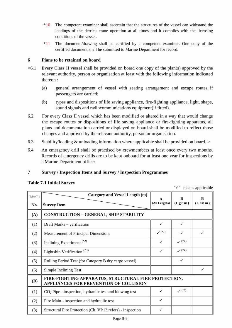
Page II-8
*10 The competent examiner shall ascertain that the structures of the vessel can withstand the loadings of the derrick crane operation at all times and it complies with the licensing conditions of the vessel.
*11 The document/drawing shall be certified by a competent examiner. One copy of the certified document shall be submitted to Marine Department for record.
6 Plans to be retained on board
<6.1 Every Class II vessel shall be provided on board one copy of the plan(s) approved by the relevant authority, person or organisation at least with the following information indicated thereon :
(a) general arrangement of vessel with seating arrangement and escape routes if passengers are carried;
(b) types and dispositions of life saving appliance, fire-fighting appliance, light, shape, sound signals and radiocommunications equipment(if fitted).
6.2 For every Class II vessel which has been modified or altered in a way that would change the escape routes or dispositions of life saving appliance or fire-fighting apparatus, all plans and documentation carried or displayed on board shall be modified to reflect those changes and approved by the relevant authority, person or organisation.
6.3 Stability/loading & unloading information where applicable shall be provided on board. >
6.4 An emergency drill shall be practised by crewmembers at least once every two months. Records of emergency drills are to be kept onboard for at least one year for inspections by a Marine Department officer.
7 Survey / Inspection Items and Survey / Inspection Programmes
Table 7-1 Initial Survey “”means applicable
Table 7-1 Category and Vessel Length (m) Survey Item
A (All Lengths)
B (L≥8 m)
B (L < 8 m) No.
(A) CONSTRUCTION – GENERAL, SHIP STABILITY
(1) Draft Marks – verification
(2) Measurement of Principal Dimensions (*1)
(3) Inclining Experiment (*2) (*4)
(4) Lightship Verification (*3) (*4)
(5) Rolling Period Test (for Category B dry cargo vessel)
(6) Simple Inclining Test
(B) FIRE-FIGHTING APPARATUS, STRUCTURAL FIRE PROTECTION, APPLIANCES FOR PREVENTION OF COLLISION
(1) CO2 Pipe - inspection, hydraulic test and blowing test (*8)
(2) Fire Main - inspection and hydraulic test
(3) Structural Fire Protection (Ch. VI/13 refers) - inspection
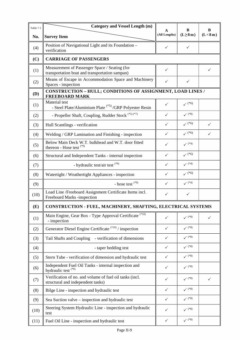
Page II-9
Table 7-1 Category and Vessel Length (m) Survey Item
A (All Lengths)
B (L≥8 m)
B (L < 8 m) No.
(4) Position of Navigational Light and its Foundation – verification
(C) CARRIAGE OF PASSENGERS
(1) Measurement of Passenger Space / Seating (for transportation boat and transportation sampan)
(2) Means of Escape in Accommodation Space and Machinery Spaces - inspection
(D) CONSTRUCTION – HULL; CONDITIONS OF ASSIGNMENT, LOAD LINES / FREEBOARD MARK
(1) Material test - Steel Plate/Aluminium Plate (*5) /GRP Polyester Resin (*6)
(2) - Propeller Shaft, Coupling, Rudder Stock (*5) (*7) (*8)
(3) Hull Scantlings - verification (*6)
(4) Welding / GRP Lamination and Finishing - inspection (*6)
(5) Below Main Deck W.T. bulkhead and W.T. door fitted thereon - Hose test (*9) (*4)
(6) Structural and Independent Tanks - internal inspection (*6)
(7) - hydraulic test/air test (*9) (*4)
(8) Watertight / Weathertight Appliances - inspection (*6)
(9) - hose test (*9) (*4)
(10) Load Line /Freeboard Assignment Certificate Items incl. Freeboard Marks -inspection
(E) CONSTRUCTION - FUEL, MACHINERY, SHAFTING, ELECTRICAL SYSTEMS
(1) Main Engine, Gear Box - Type Approval Certificate (*10)
- inspection (*8)
(2) Generator Diesel Engine Certificate (*10) / inspection (*8)
(3) Tail Shafts and Coupling - verification of dimensions (*8)
(4) - taper bedding test (*8)
(5) Stern Tube - verification of dimension and hydraulic test (*8)
(6) Independent Fuel Oil Tanks - internal inspection and hydraulic test (*9) (*8)
(7) Verification of no. and volume of fuel oil tanks (incl. structural and independent tanks) (*8)
(8) Bilge Line - inspection and hydraulic test (*8)
(9) Sea Suction valve – inspection and hydraulic test (*8)
(10) Steering System Hydraulic Line - inspection and hydraulic test (*8)
(11) Fuel Oil Line - inspection and hydraulic test (*8)
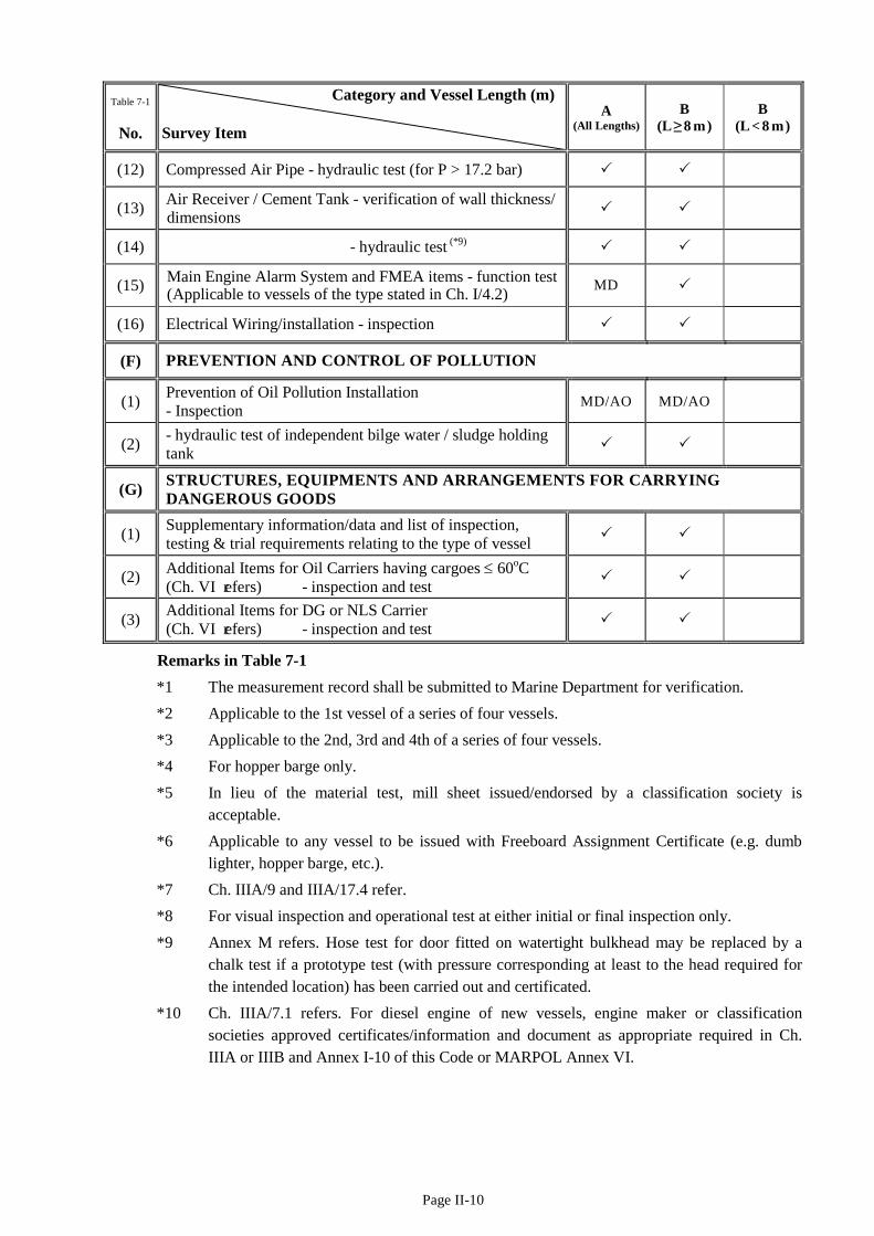
Page II-10
Table 7-1 Category and Vessel Length (m) Survey Item
A (All Lengths)
B (L≥8 m)
B (L < 8 m) No.
(12) Compressed Air Pipe - hydraulic test (for P > 17.2 bar)
(13) Air Receiver / Cement Tank - verification of wall thickness/ dimensions
(14) - hydraulic test (*9)
(15) Main Engine Alarm System and FMEA items - function test (Applicable to vessels of the type stated in Ch. I/4.2) MD
(16) Electrical Wiring/installation - inspection
(F) PREVENTION AND CONTROL OF POLLUTION
(1) Prevention of Oil Pollution Installation - Inspection MD/AO MD/AO
(2) - hydraulic test of independent bilge water / sludge holding tank
(G) STRUCTURES, EQUIPMENTS AND ARRANGEMENTS FOR CARRYING DANGEROUS GOODS
(1) Supplementary information/data and list of inspection, testing & trial requirements relating to the type of vessel
(2) Additional Items for Oil Carriers having cargoes ≤ 60oC (Ch. VI refers) - inspection and test
(3) Additional Items for DG or NLS Carrier (Ch. VI refers) - inspection and test
Remarks in Table 7-1 *1 The measurement record shall be submitted to Marine Department for verification. *2 Applicable to the 1st vessel of a series of four vessels. *3 Applicable to the 2nd, 3rd and 4th of a series of four vessels. *4 For hopper barge only. *5 In lieu of the material test, mill sheet issued/endorsed by a classification society is
acceptable. *6 Applicable to any vessel to be issued with Freeboard Assignment Certificate (e.g. dumb
lighter, hopper barge, etc.). *7 Ch. IIIA/9 and IIIA/17.4 refer. *8 For visual inspection and operational test at either initial or final inspection only. *9 Annex M refers. Hose test for door fitted on watertight bulkhead may be replaced by a
chalk test if a prototype test (with pressure corresponding at least to the head required for the intended location) has been carried out and certificated.
*10 Ch. IIIA/7.1 refers. For diesel engine of new vessels, engine maker or classification societies approved certificates/information and document as appropriate required in Ch. IIIA or IIIB and Annex I-10 of this Code or MARPOL Annex VI.
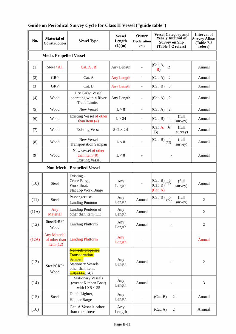
Page II-11
Guide on Periodical Survey Cycle for Class II Vessel (“guide table”)
No. Material of Construction Vessel Type
Vessel Length (L)(m)
Owner Declaration
(*1)
Vessel Category and Yearly Interval of
Survey on Slip (Table 7-2 refers)
Interval of Survey Afloat
(Table 7-3 refers)
Mech. Propelled Vessel
(1) Steel / Al. Cat. A , B Any Length - (Cat. A, B) 2 Annual
(2) GRP Cat. A Any Length - (Cat. A) 2 Annual
(3) GRP Cat. B Any Length - (Cat. B) 3 Annual
(4) Wood Dry Cargo Vessel
operating within River Trade Limits -
Any Length - (Cat. A) 2 Annual
(5) Wood New Vessel L ≥ 8 - (Cat. A) 2 Annual
(6) Wood Existing Vessel of other than item (4) L ≥ 24 - (Cat. B) 4 (full
survey) Annual
(7) Wood Existing Vessel 8≤L<24 - (Cat. A, B)
6 (full survey) Annual
(8) Wood New Vessel Transportation Sampan L < 8 - (Cat. B) 4
(*2) (full
survey) Annual
(9) Wood New vessel of other
than item (8), Existing Vessel
L < 8 - - Annual
Non-Mech. Propelled Vessel
(10) Steel
Existing - Crane Barge, Work Boat, Flat Top Work Barge
Any Length -
(Cat. B) 6 (Cat. B) (*2) (Cat. A)
(full survey) Annual
(11) Steel Passenger use Landing Pontoon
Any Length Annual (Cat. B) 6
(*2) (full
survey) 2
(11A) Any Material
Landing Pontoon of other than item (11)
Any Length Annual - 2
(12) Steel/GRP/
Wood Landing Platform Any
Length Annual - 2
(12A) Any Material of other than
item (12) Landing Platform Any
Length - Annual
(13) Steel/GRP/
Wood
Non-self propelled Transportation Sampan, Stationary Vessels other than items (10),(11),(14))
Any Length Annual - 2
(14) Stationary Vessels
(except Kitchen Boat) with LXB ≤ 25
Any Length Annual - 3
(15) Steel Dumb Lighter, Hopper Barge
Any Length - (Cat. B) 2 Annual
(16) Cat. A Vessels other than the above
Any Length (Cat. A) 2 Annual
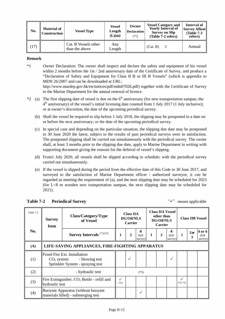
Page II-12
No. Material of Construction Vessel Type
Vessel Length (L)(m)
Owner Declaration
(*1)
Vessel Category and Yearly Interval of
Survey on Slip (Table 7-2 refers)
Interval of Survey Afloat
(Table 7-3 refers)
(17) Cat. B Vessels other than the above
Any Length (Cat. B) 3 Annual
Remark
*1 Owner Declaration: The owner shall inspect and declare the safety and equipment of his vessel within 2 months before the 1st / 2nd anniversary date of the Certificate of Survey, and produce a “Declaration of Safety and Equipment for Class II B or III B Vessels” (which is appendix to MDN 26/2007 and can be downloaded at URL: http://www.mardep.gov.hk/en/notices/pdf/mdn07026.pdf) together with the Certificate of Survey to the Marine Department for the annual renewal of licence.
*2 (a) The first slipping date of vessel is due on the 6th anniversary (for new transportation sampan, the 4th anniversary) of the vessel’s initial licensing date counted from 1 July 2017 (1 July inclusive); or at owner’s discretion, the date of the upcoming periodical survey.
(b) Shall the vessel be required to slip before 1 July 2018, the slipping may be postponed to a date on or before the next anniversary; or the date of the upcoming periodical survey.
(c) In special case and depending on the particular situation, the slipping due date may be postponed to 30 June 2020 the latest, subject to the results of past periodical surveys were in satisfaction. The postponed slipping shall be carried out simultaneously with the periodical survey. The owner shall, at least 3 months prior to the slipping due date, apply to Marine Department in writing with supporting document giving the reasons for the deferral of vessel’s slipping.
(d) From1 July 2020, all vessels shall be slipped according to schedule; with the periodical survey carried out simultaneously.
(e) If the vessel is slipped during the period from the effective date of this Code to 30 June 2017, and surveyed to the satisfaction of Marine Department officer / authorized surveyor, it can be regarded as meeting the requirement of (a), and the next slipping date may be scheduled for 2023 (for L<8 m wooden new transportation sampan, the next slipping date may be scheduled for 2021).
Table 7-2 Periodical Survey “”means applicable
Table 7-2
Survey Item
Class/Category/Type of Vessel
Class IIA DG/Oil/NLS
Carrier
Class IIA Vessel other than
DG/Oil/NLS Carrier
Class IIB Vessel
No. Survey Intervals (*1)(*2) 1 2
4 (full
survey) 1 2
4 (full
survey) 1 2 or
3 4 or 6
(full survey)
(A) LIFE-SAVING APPLIANCES, FIRE-FIGHTING APPARATUS
(1) Fixed Fire Ext. Installation CO2 system - blowing test Sprinkler System - spraying test
(2) - hydraulic test (*3)
(3) Fire Extinguisher, CO2 Bottle - refill and hydraulic test
(*4)
(*4, *5)
(4) Buoyant Apparatus (without buoyant materials filled) - submerging test
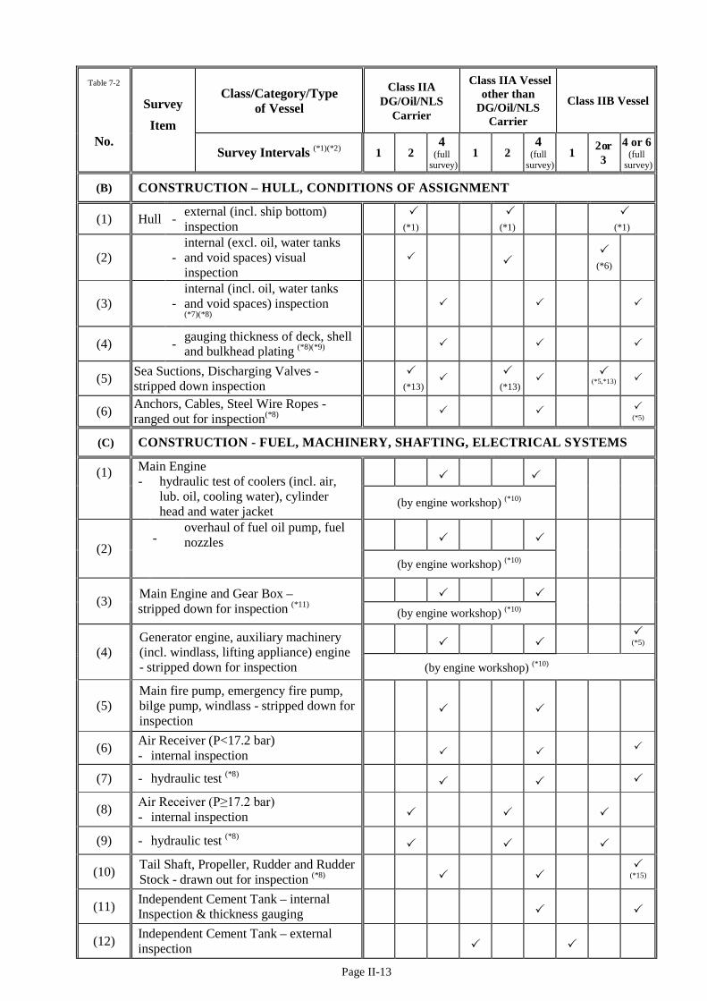
Page II-13
Table 7-2
Survey Item
Class/Category/Type of Vessel
Class IIA DG/Oil/NLS
Carrier
Class IIA Vessel other than
DG/Oil/NLS Carrier
Class IIB Vessel
No. Survey Intervals (*1)(*2) 1 2
4 (full
survey) 1 2
4 (full
survey) 1 2 or
3 4 or 6
(full survey)
(B) CONSTRUCTION – HULL, CONDITIONS OF ASSIGNMENT
(1) Hull - external (incl. ship bottom) inspection
(*1) (*1)
(*1)
(2) - internal (excl. oil, water tanks and void spaces) visual inspection
(*6)
(3) - internal (incl. oil, water tanks and void spaces) inspection (*7)(*8)
(4) - gauging thickness of deck, shell and bulkhead plating (*8)(*9)
(5) Sea Suctions, Discharging Valves - stripped down inspection
(*13) (*13)
(*5,*13)
(6) Anchors, Cables, Steel Wire Ropes - ranged out for inspection(*8)
(*5)
(C) CONSTRUCTION - FUEL, MACHINERY, SHAFTING, ELECTRICAL SYSTEMS
(1) Main Engine - hydraulic test of coolers (incl. air,
lub. oil, cooling water), cylinder head and water jacket
(by engine workshop) (*10)
(2) -
overhaul of fuel oil pump, fuel nozzles
(by engine workshop) (*10)
(3) Main Engine and Gear Box – stripped down for inspection (*11)
(by engine workshop) (*10)
(4) Generator engine, auxiliary machinery (incl. windlass, lifting appliance) engine - stripped down for inspection
(*5) (by engine workshop) (*10)
(5) Main fire pump, emergency fire pump, bilge pump, windlass - stripped down for inspection
(6) Air Receiver (P<17.2 bar) - internal inspection
(7) - hydraulic test (*8)
(8) Air Receiver (P≥17.2 bar) - internal inspection
(9) - hydraulic test (*8)
(10) Tail Shaft, Propeller, Rudder and Rudder Stock - drawn out for inspection (*8)
(*15)
(11) Independent Cement Tank – internal Inspection & thickness gauging
(12) Independent Cement Tank – external inspection
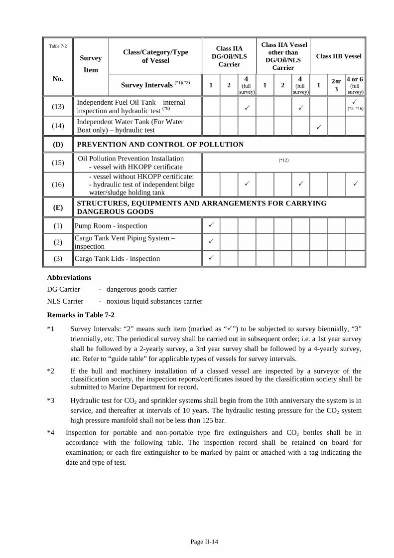
Page II-14
Table 7-2
Survey Item
Class/Category/Type of Vessel
Class IIA DG/Oil/NLS
Carrier
Class IIA Vessel other than
DG/Oil/NLS Carrier
Class IIB Vessel
No. Survey Intervals (*1)(*2) 1 2
4 (full
survey) 1 2
4 (full
survey) 1 2 or
3 4 or 6
(full survey)
(13) Independent Fuel Oil Tank – internal inspection and hydraulic test (*8)
(*5, *16)
(14) Independent Water Tank (For Water Boat only) – hydraulic test
(D) PREVENTION AND CONTROL OF POLLUTION
(15) Oil Pollution Prevention Installation - vessel with HKOPP certificate
(*12)
(16) - vessel without HKOPP certificate: - hydraulic test of independent bilge
water/sludge holding tank
(E) STRUCTURES, EQUIPMENTS AND ARRANGEMENTS FOR CARRYING DANGEROUS GOODS
(1) Pump Room - inspection
(2) Cargo Tank Vent Piping System – inspection
(3) Cargo Tank Lids - inspection
Abbreviations DG Carrier - dangerous goods carrier NLS Carrier - noxious liquid substances carrier
Remarks in Table 7-2
*1 Survey Intervals: “2” means such item (marked as “”) to be subjected to survey biennially, “3” triennially, etc. The periodical survey shall be carried out in subsequent order; i.e. a 1st year survey shall be followed by a 2-yearly survey, a 3rd year survey shall be followed by a 4-yearly survey, etc. Refer to “guide table” for applicable types of vessels for survey intervals.
*2 If the hull and machinery installation of a classed vessel are inspected by a surveyor of the classification society, the inspection reports/certificates issued by the classification society shall be submitted to Marine Department for record.
*3 Hydraulic test for CO2 and sprinkler systems shall begin from the 10th anniversary the system is in service, and thereafter at intervals of 10 years. The hydraulic testing pressure for the CO2 system high pressure manifold shall not be less than 125 bar.
*4 Inspection for portable and non-portable type fire extinguishers and CO2 bottles shall be in accordance with the following table. The inspection record shall be retained on board for examination; or each fire extinguisher to be marked by paint or attached with a tag indicating the date and type of test.
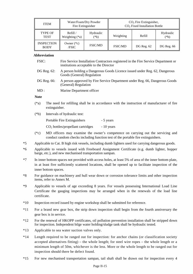
Page II-15
ITEM Water/Foam/Dry Powder Fire Extinguisher
CO2 Fire Extinguisher, CO2 Fixed Installation Bottle
TYPE OF TEST
Refill / Weighting (*a)
Hydraulic (*b) Weighting Refill
Hydraulic (*b)
INSPECTION BODY
Owner (*c) /FSIC FSIC/MD FSIC/MD DG Reg. 62 DG Reg. 66
Abbreviation FSIC: Fire Service Installation Contractors registered in the Fire Service Department or
institutions acceptable to the Director DG Reg. 62: A person holding a Dangerous Goods Licence issued under Reg. 62, Dangerous
Goods (General) Regulation DG Reg. 66: A person approved by Fire Service Department under Reg. 66, Dangerous Goods
(General) Regulation MD : Marine Department officer
Note
(*a) The need for refilling shall be in accordance with the instruction of manufacturer of fire extinguisher.
(*b) Intervals of hydraulic test:
Portable Fire Extinguishers - 5 years
CO2 bottles/propellant cartridges - 10 years
(*c) MD officers may examine the owner’s competence on carrying out the servicing and conduct random checks including function test of the portable fire extinguishers.
*5 Applicable to Cat. B high risk vessels, including dumb lighters used for carrying dangerous goods. *6 Applicable to vessels issued with Freeboard Assignment Certificate (e.g. dumb lighter, hopper
barge, etc.), and new mechanised transportation sampan.
*7 In inner bottom spaces not provided with access holes, at least 5% of area of the inner bottom plate, in at least five sufficiently scattered locations, shall be opened up to facilitate inspection of the inner bottom spaces.
*8 For guidance on machinery and hull wear down or corrosion tolerance limits and other inspection items, refer to Annex M.
*9 Applicable to vessels of age exceeding 8 years. For vessels possessing International Load Line Certificate the gauging inspections may be arranged when in the renewals of the load line certificate.
*10 Inspection record issued by engine workshop shall be submitted for reference.
*11 For a brand new gear box, the strip down inspection shall begin from the fourth anniversary the gear box is in service.
*12 For the renewal of HKOPP certificates, oil pollution prevention installation shall be stripped down for inspection. Independent bilge water holding/sludge tank shall be hydraulic tested.
*13 Applicable to sea water suction valves only.
*14 Length required to be ranged out for inspection: for anchor chains (or classification society accepted alternatives fitting) – the whole length; for steel wire ropes – the whole length or a minimum length of 50m, whichever is the less. More or the whole length to be ranged out for inspection should there be defect found.
*15 For new mechanised transportation sampan, tail shaft shall be drawn out for inspection every 4
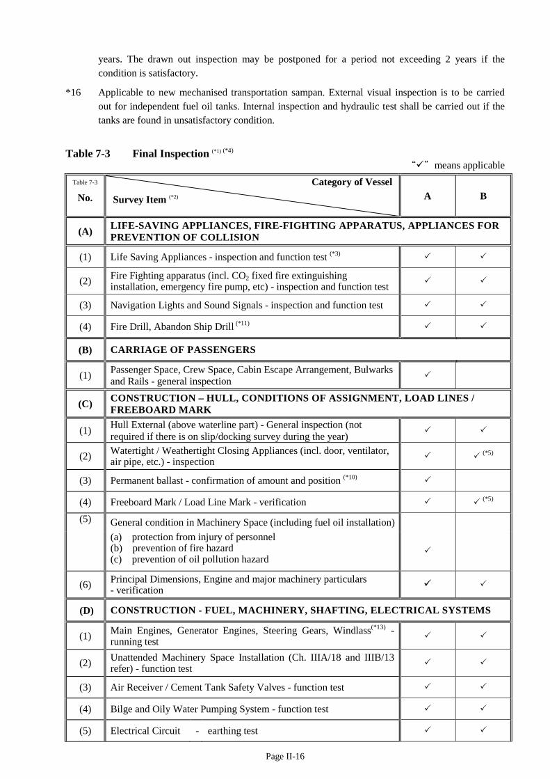
Page II-16
years. The drawn out inspection may be postponed for a period not exceeding 2 years if the condition is satisfactory.
*16 Applicable to new mechanised transportation sampan. External visual inspection is to be carried out for independent fuel oil tanks. Internal inspection and hydraulic test shall be carried out if the tanks are found in unsatisfactory condition.
Table 7-3 Final Inspection (*1) (*4)
“”means applicable Table 7-3
No. Category of Vessel
Survey Item (*2) A B
(A) LIFE-SAVING APPLIANCES, FIRE-FIGHTING APPARATUS, APPLIANCES FOR PREVENTION OF COLLISION
(1) Life Saving Appliances - inspection and function test (*3)
(2) Fire Fighting apparatus (incl. CO2 fixed fire extinguishing installation, emergency fire pump, etc) - inspection and function test
(3) Navigation Lights and Sound Signals - inspection and function test
(4) Fire Drill, Abandon Ship Drill (*11)
(B) CARRIAGE OF PASSENGERS
(1) Passenger Space, Crew Space, Cabin Escape Arrangement, Bulwarks and Rails - general inspection
(C) CONSTRUCTION – HULL, CONDITIONS OF ASSIGNMENT, LOAD LINES / FREEBOARD MARK
(1) Hull External (above waterline part) - General inspection (not required if there is on slip/docking survey during the year)
(2) Watertight / Weathertight Closing Appliances (incl. door, ventilator, air pipe, etc.) - inspection (*5)
(3) Permanent ballast - confirmation of amount and position (*10)
(4) Freeboard Mark / Load Line Mark - verification (*5)
(5)
General condition in Machinery Space (including fuel oil installation)
(a) protection from injury of personnel (b) prevention of fire hazard (c) prevention of oil pollution hazard
(6) Principal Dimensions, Engine and major machinery particulars - verification
(D) CONSTRUCTION - FUEL, MACHINERY, SHAFTING, ELECTRICAL SYSTEMS
(1) Main Engines, Generator Engines, Steering Gears, Windlass(*13) - running test
(2) Unattended Machinery Space Installation (Ch. IIIA/18 and IIIB/13 refer) - function test
(3) Air Receiver / Cement Tank Safety Valves - function test
(4) Bilge and Oily Water Pumping System - function test
(5) Electrical Circuit - earthing test
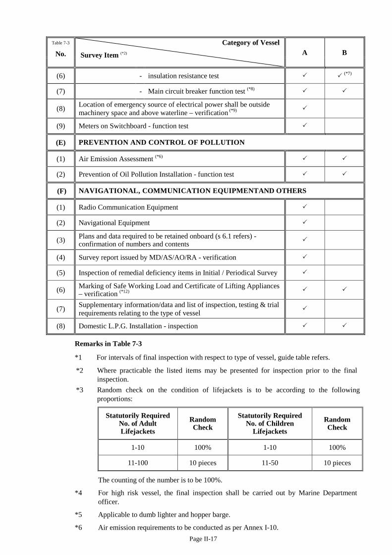
Page II-17
Table 7-3
No. Category of Vessel
Survey Item (*2) A B
(6) - insulation resistance test (*7)
(7) - Main circuit breaker function test (*8)
(8) Location of emergency source of electrical power shall be outside machinery space and above waterline – verification (*9)
(9) Meters on Switchboard - function test
(E) PREVENTION AND CONTROL OF POLLUTION
(1) Air Emission Assessment (*6)
(2) Prevention of Oil Pollution Installation - function test
(F) NAVIGATIONAL, COMMUNICATION EQUIPMENTAND OTHERS
(1) Radio Communication Equipment
(2) Navigational Equipment
(3) Plans and data required to be retained onboard (s 6.1 refers) - confirmation of numbers and contents
(4) Survey report issued by MD/AS/AO/RA - verification
(5) Inspection of remedial deficiency items in Initial / Periodical Survey
(6) Marking of Safe Working Load and Certificate of Lifting Appliances – verification (*12)
(7) Supplementary information/data and list of inspection, testing & trial requirements relating to the type of vessel
(8) Domestic L.P.G. Installation - inspection
Remarks in Table 7-3
*1 For intervals of final inspection with respect to type of vessel, guide table refers.
*2 Where practicable the listed items may be presented for inspection prior to the final inspection.
*3 Random check on the condition of lifejackets is to be according to the following proportions:
Statutorily Required No. of Adult Lifejackets
Random Check
Statutorily Required No. of Children
Lifejackets Random Check
1-10 100% 1-10 100%
11-100 10 pieces 11-50 10 pieces
The counting of the number is to be 100%.
*4 For high risk vessel, the final inspection shall be carried out by Marine Department officer.
*5 Applicable to dumb lighter and hopper barge.
*6 Air emission requirements to be conducted as per Annex I-10.

Page II-18
*7 Applicable to any vessel other than Category B wooden construction vessel. For vessels other than high risk vessels, a valid EMSD registered electrical contractor (REC) issued electrical system insulation test report (with the test being conducted by an EMSD registered electrical worker (REW) within 2 weeks prior to the final inspection) is acceptable in lieu of the insulation resistance test inspection responsible by MD officer or authorized inspection personnels. A valid electrical system insulation test report shall include the relevant necessary information. A valid electrical system insulation test report issued by an authorized inspection personnel is acceptable.
*8 Applicable to any vessel fitted with generator of each capacity exceeding 50 kW.
*9 Applicable to only a vessel which is still a new vessel when the reference to “the commencement date of the Survey Regulation” in the definition of “new vessel” under Ch. I/3.1 is substituted by “29 November 2014”.
*10 In addition to the visual inspection, owner’s declaration on the amount and disposition of the ballast weights to be furnished to Marine Department for record.
*11 Applicable to any mechanized oil carrier, dangerous goods carrier and noxious liquid substances carrier; and any types of mechanized vessels plying beyond Hong Kong waters.
*12 The following document / certificates certified by competent examiner shall be presented in final inspection for verification of validity:
i) Register of Lifting Appliance & Lifting Gear (Form 1);
ii) Certificate of Test and Examination of Winches, Derricks and their Accessory Gear (Form 2)(if applicable);
iii) Certificate of Test and Examination of Lifting Appliance and their Accessory Gear other than Derricks (Form 3)(if applicable).
*13 For high risk vessels (including dumb lighter used for carrying dangerous goods) inspecting officer will carry out external visual inspection and running test. Owner of vessel shall confirm by writing that the windlass has been properly repaired and maintained.
8 Large Cargo Vessel
8.1 “Large Cargo Vessel”: means local licensed cargo vessel of overall length exceeding 75 metres. These vessels are prohibited to enter the typhoon shelter and must be anchored or to leave Hong Kong waters during typhoon period, consequently reinforcement of relevant shipboard equipment and installation as stated in sections 8.2 and 8.3 are required.
8.2 In addition to the requirements as stated in this Code, following equipment and installation are also required:
(a) Non-mechanically propelled vessel: one kind of communication equipment, anchor and windlass;
(b) Mechanically propelled vessel: compass, echo sounder, radar, VHF (Very High Frequency) radio telephone (with licence issued by Communications Authority, Hong Kong), anchor, windlass and inclinator.
8.3 Standard of anchor and anchoring machine must comply with relevant strength and calculation requirements of classification societies or an equivalent Standard.
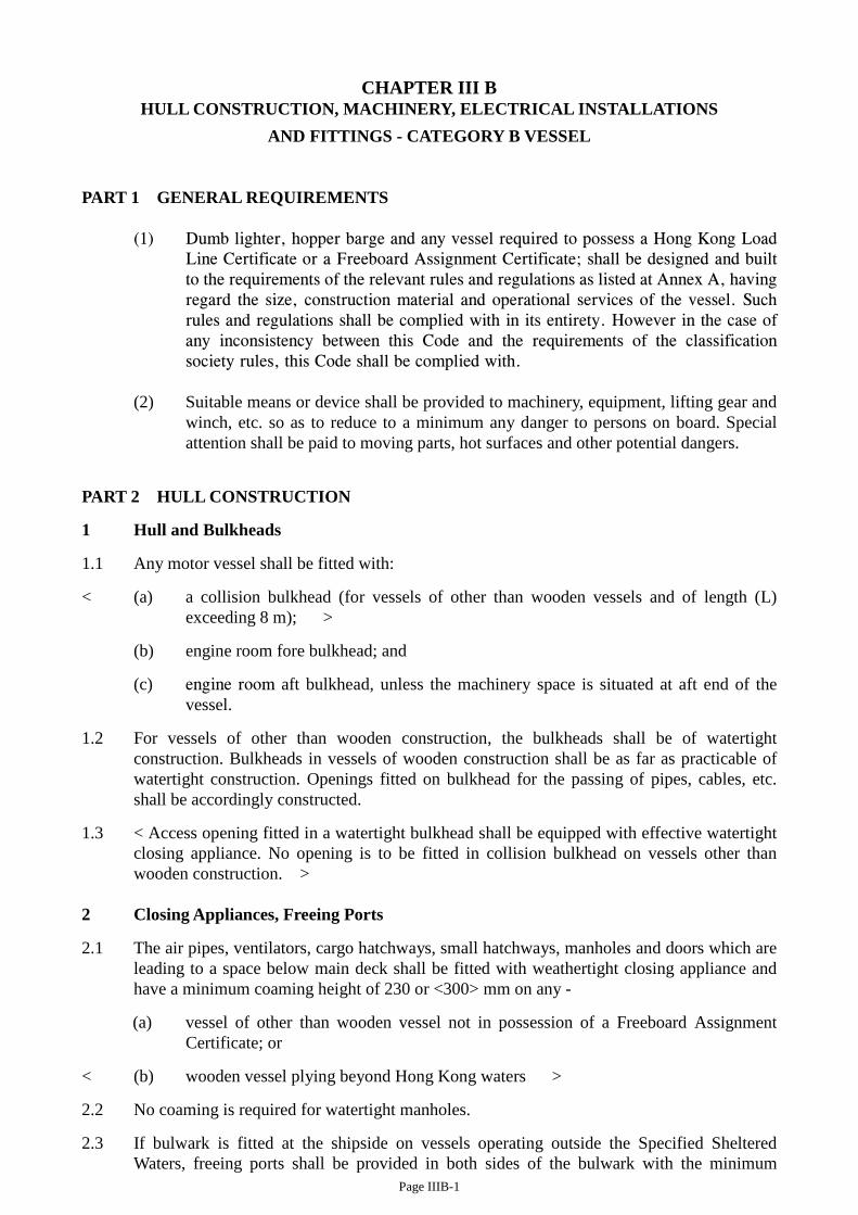
Page IIIB-1
CHAPTER III B HULL CONSTRUCTION, MACHINERY, ELECTRICAL INSTALLATIONS
AND FITTINGS - CATEGORY B VESSEL
PART 1 GENERAL REQUIREMENTS
(1) Dumb lighter, hopper barge and any vessel required to possess a Hong Kong Load Line Certificate or a Freeboard Assignment Certificate; shall be designed and built to the requirements of the relevant rules and regulations as listed at Annex A, having regard the size, construction material and operational services of the vessel. Such rules and regulations shall be complied with in its entirety. However in the case of any inconsistency between this Code and the requirements of the classification society rules, this Code shall be complied with.
(2) Suitable means or device shall be provided to machinery, equipment, lifting gear and
winch, etc. so as to reduce to a minimum any danger to persons on board. Special attention shall be paid to moving parts, hot surfaces and other potential dangers.
PART 2 HULL CONSTRUCTION
1 Hull and Bulkheads
1.1 Any motor vessel shall be fitted with:
< (a) a collision bulkhead (for vessels of other than wooden vessels and of length (L) exceeding 8 m); >
(b) engine room fore bulkhead; and
(c) engine room aft bulkhead, unless the machinery space is situated at aft end of the vessel.
1.2 For vessels of other than wooden construction, the bulkheads shall be of watertight construction. Bulkheads in vessels of wooden construction shall be as far as practicable of watertight construction. Openings fitted on bulkhead for the passing of pipes, cables, etc. shall be accordingly constructed.
1.3 < Access opening fitted in a watertight bulkhead shall be equipped with effective watertight closing appliance. No opening is to be fitted in collision bulkhead on vessels other than wooden construction. >
2 Closing Appliances, Freeing Ports
2.1 The air pipes, ventilators, cargo hatchways, small hatchways, manholes and doors which are leading to a space below main deck shall be fitted with weathertight closing appliance and have a minimum coaming height of 230 or <300> mm on any -
(a) vessel of other than wooden vessel not in possession of a Freeboard Assignment Certificate; or
< (b) wooden vessel plying beyond Hong Kong waters >
2.2 No coaming is required for watertight manholes.
2.3 If bulwark is fitted at the shipside on vessels operating outside the Specified Sheltered Waters, freeing ports shall be provided in both sides of the bulwark with the minimum
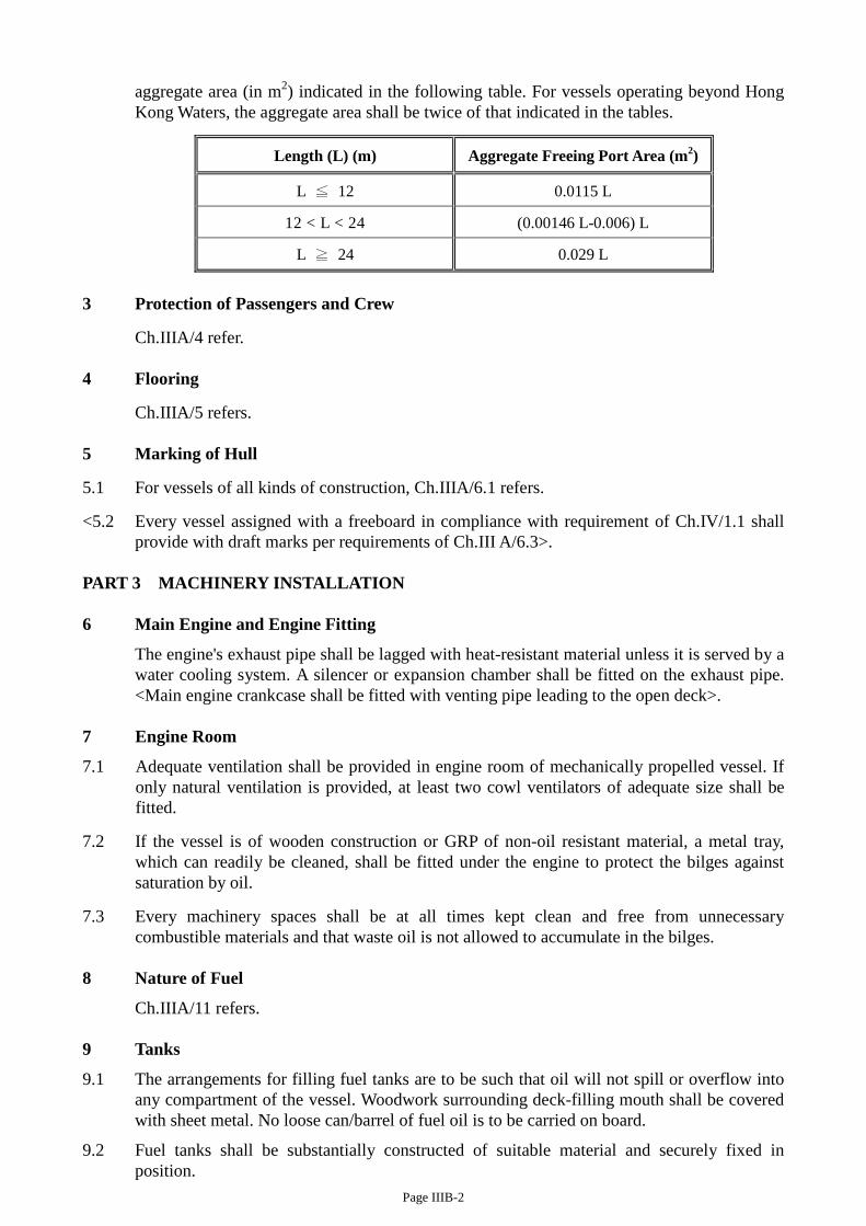
Page IIIB-2
aggregate area (in m2) indicated in the following table. For vessels operating beyond Hong Kong Waters, the aggregate area shall be twice of that indicated in the tables.
Length (L) (m) Aggregate Freeing Port Area (m2)
L ≦ 12 0.0115 L
12 < L < 24 (0.00146 L-0.006) L
L ≧ 24 0.029 L
3 Protection of Passengers and Crew
Ch.IIIA/4 refer. 4 Flooring
Ch.IIIA/5 refers. 5 Marking of Hull
5.1 For vessels of all kinds of construction, Ch.IIIA/6.1 refers.
<5.2 Every vessel assigned with a freeboard in compliance with requirement of Ch.IV/1.1 shall provide with draft marks per requirements of Ch.III A/6.3>.
PART 3 MACHINERY INSTALLATION 6 Main Engine and Engine Fitting
The engine's exhaust pipe shall be lagged with heat-resistant material unless it is served by a water cooling system. A silencer or expansion chamber shall be fitted on the exhaust pipe. <Main engine crankcase shall be fitted with venting pipe leading to the open deck>.
7 Engine Room
7.1 Adequate ventilation shall be provided in engine room of mechanically propelled vessel. If only natural ventilation is provided, at least two cowl ventilators of adequate size shall be fitted.
7.2 If the vessel is of wooden construction or GRP of non-oil resistant material, a metal tray, which can readily be cleaned, shall be fitted under the engine to protect the bilges against saturation by oil.
7.3 Every machinery spaces shall be at all times kept clean and free from unnecessary combustible materials and that waste oil is not allowed to accumulate in the bilges.
8 Nature of Fuel
Ch.IIIA/11 refers. 9 Tanks
9.1 The arrangements for filling fuel tanks are to be such that oil will not spill or overflow into any compartment of the vessel. Woodwork surrounding deck-filling mouth shall be covered with sheet metal. No loose can/barrel of fuel oil is to be carried on board.
9.2 Fuel tanks shall be substantially constructed of suitable material and securely fixed in position.

Page IIIB-3
9.3.1 The materials for water tank of water boats shall be of steel, aluminum or glass reinforced fibre (GRP) subject to:
(a) the tanks are watertight;
(b) the tanks do not affect the stability, structure and safety of the vessel;
(c) the shell of water tank shall not be formed as any part of ship hull unless the ship hull is constructed of steel or aluminum;
(d) the physical construction and installation of the water tank, fittings and piping are up to the Director’s satisfaction;
(e) the tank coating / paint used shall not cause any health and hygiene risk; and
(f) the requirements from other Department (if any) shall be fulfilled.
9.3.2 If water boat requires ballasting, detail information, drawing and calculation of the ballast tank and ballast system shall be prior approved by the Director.
10 Pumping and Piping Arrangement
Ch.IIIA/13 refers. 11 Bilge Pumping Arrangement
A hand or electrical operated bilge pump of sufficient capacity shall be fitted for pumping out water in the bilge. On dumb lighters, a portable type submerged pump is accepted for the purpose.
12 Compressed Air System
Ch.IIIA/15 refers. 13 Wheelhouse - Engine room Communication
Ch.IIIA/18 refers
Note For the purpose of “combined coxswain” operation, any existing vessel of length less than 24m, total power not more than 750 kW (1,000 HP), and operating within waters of Hong Kong, fittings of a fixed fire detection (operated by smoke detectors) and fire alarm system for engine room can be waived, provided regular surveillance (such as through tale-tell pipe or transparent glass view-hole fittings etc.) can be exercised from outside engine room or control station by the coxswain or a crewmember.
14 Installation for Prevention of Oil Pollution
Ch.IIIA/19 refers. 15 Electrical Installations
Ch.IIIA/Part 4 refers.

Page VIII-1
CHAPTER VIII
LIGHTS, SHAPES AND SOUND SIGNALS
1 General 1.1 Unless indicated otherwise, this chapter (including amendments made therein) applies to
all vessels with effect from 1 July 2016.
1.2 Lights, shapes and sound signals provided for navigational purpose must be in accordance with the provisions of the Merchant Shipping (Safety) (Signals of Distress and Prevention of Collisions) Regulations, Cap. 369 sub. leg. N, which gives effect to the International Regulations for Preventing Collisions at Sea 1972 (COLREG), as amended.
1.3 All lanterns and sound signals must be of the type approved/certified by the Marine Department, or the Maritime Administration of a convention country.
All lanterns and sound signals fitted on new vesselNote 1; or replacement of these lights/signals on existing vessel must be of the type approved/certified by the Marine Department, or the Maritime Administration of a convention country or an authorized organization (definition in Ch. I/3.1 refers). Each navigation light must be accompanied by a type-approval certificate with unique serial number.
1.4 Where applicable special signals as required in the International Code of Signals published by the International Maritime Organization must be exhibited.
1.5 For ease of reference for meeting relevant provisions of the Regulations mentioned in section 1.1, the following sections, tables or diagrams indicate the signal appliances a vessel must exhibit when underway/towing/being towed, of type and length as indicated.
2 Definitions
For the purpose of this chapter, except where the context otherwise requires:
(a) The words "length (L)" and "breadth" of a vessel mean her length overall and extreme breadth (as defined in Ch. I/3.1).
(b) The term "height above the hull" means height above the uppermost continuous deck. This height shall be measured from the position vertically beneath the location of the light.
3 Alternative Lights
3.1 All vessels of L ≥ 24.4 metres shall carry a complete set of alternative (standby) lanterns for the masthead lights, side lights (P. and S.) and stern light.
3.2 On vessels carrying dangerous goods, all lanterns including alternative lanterns shall be of electric type. On other vessels the alternative lanterns may be either electric or oil type.
3.3 One set of spare bulbs (one per light) shall be carried for the electric lanterns. A set of spare chimneys (one per light) shall be carried for the oil lanterns.
4 Lights and Sound Signals Note1 Applicable to a vessel which is when the reference to “the commencement date” of the Survey
Regulation in the definition of “new vessel” under section 2 of the Survey Regulation is substituted by “3 March 2017”.
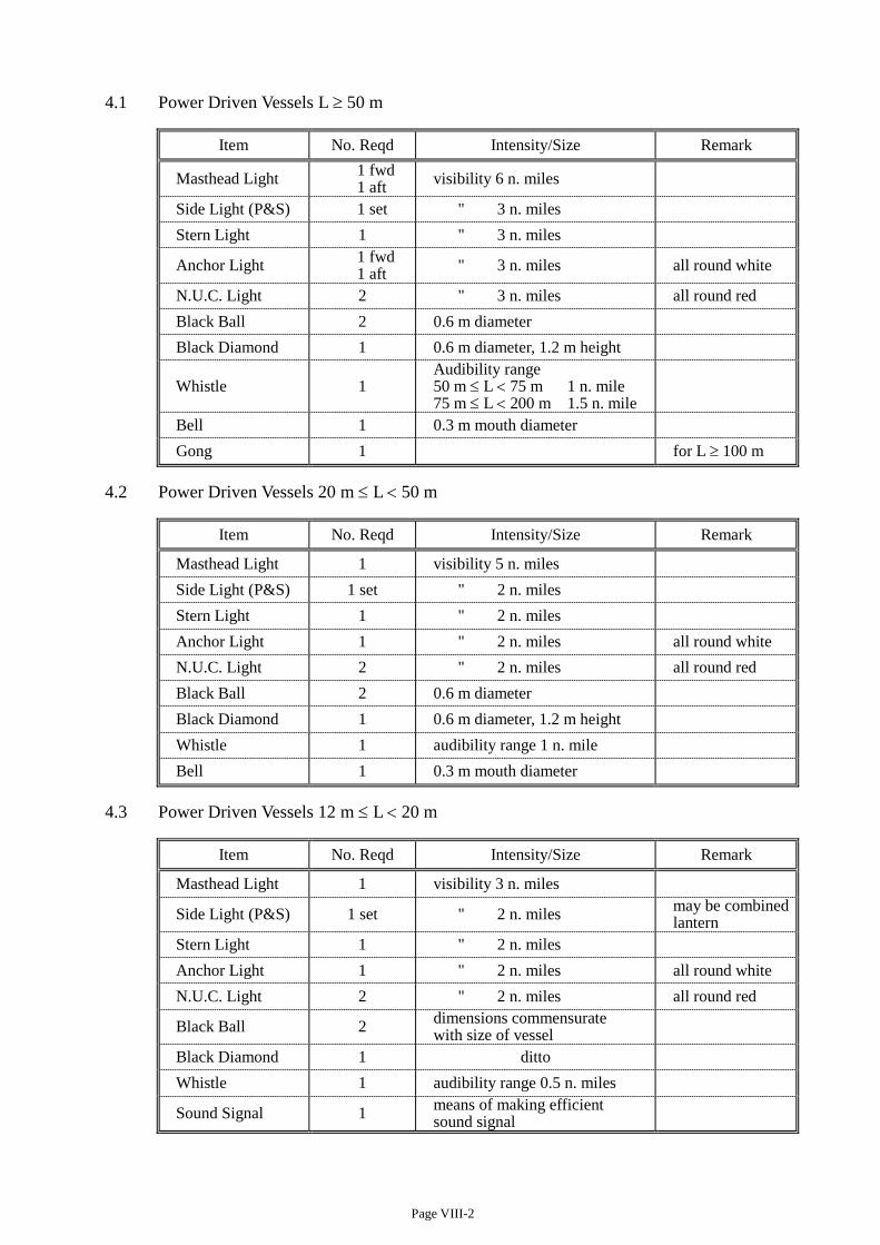
Page VIII-2
4.1 Power Driven Vessels L ≥ 50 m
Item No. Reqd Intensity/Size Remark
Masthead Light 1 fwd 1 aft visibility 6 n. miles
Side Light (P&S) 1 set " 3 n. miles Stern Light 1 " 3 n. miles
Anchor Light 1 fwd 1 aft " 3 n. miles all round white
N.U.C. Light 2 " 3 n. miles all round red Black Ball 2 0.6 m diameter Black Diamond 1 0.6 m diameter, 1.2 m height
Whistle 1 Audibility range 50 m ≤ L < 75 m 1 n. mile 75 m ≤ L < 200 m 1.5 n. mile
Bell 1 0.3 m mouth diameter Gong 1 for L ≥ 100 m
4.2 Power Driven Vessels 20 m ≤ L < 50 m
Item No. Reqd Intensity/Size Remark
Masthead Light 1 visibility 5 n. miles Side Light (P&S) 1 set " 2 n. miles Stern Light 1 " 2 n. miles Anchor Light 1 " 2 n. miles all round white N.U.C. Light 2 " 2 n. miles all round red Black Ball 2 0.6 m diameter Black Diamond 1 0.6 m diameter, 1.2 m height Whistle 1 audibility range 1 n. mile Bell 1 0.3 m mouth diameter
4.3 Power Driven Vessels 12 m ≤ L < 20 m
Item No. Reqd Intensity/Size Remark
Masthead Light 1 visibility 3 n. miles
Side Light (P&S) 1 set " 2 n. miles may be combined lantern
Stern Light 1 " 2 n. miles Anchor Light 1 " 2 n. miles all round white N.U.C. Light 2 " 2 n. miles all round red
Black Ball 2 dimensions commensurate with size of vessel
Black Diamond 1 ditto Whistle 1 audibility range 0.5 n. miles
Sound Signal 1 means of making efficient sound signal
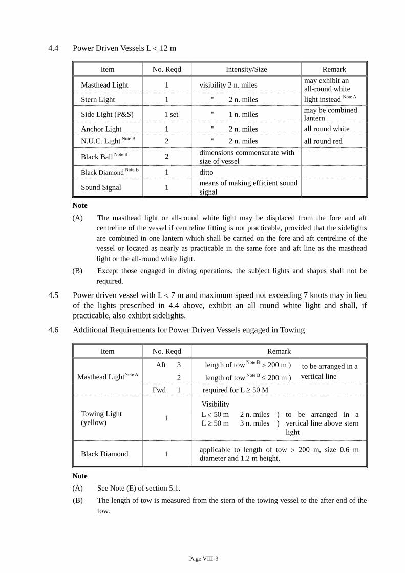
Page VIII-3
4.4 Power Driven Vessels L < 12 m
Item No. Reqd Intensity/Size Remark
Masthead Light 1 visibility 2 n. miles may exhibit an all-round white
Stern Light 1 " 2 n. miles light instead Note A
Side Light (P&S) 1 set " 1 n. miles may be combined lantern
Anchor Light 1 " 2 n. miles all round white
N.U.C. Light Note B 2 " 2 n. miles all round red
Black Ball Note B 2 dimensions commensurate with size of vessel
Black Diamond Note B 1 ditto
Sound Signal 1 means of making efficient sound signal
Note (A) The masthead light or all-round white light may be displaced from the fore and aft
centreline of the vessel if centreline fitting is not practicable, provided that the sidelights are combined in one lantern which shall be carried on the fore and aft centreline of the vessel or located as nearly as practicable in the same fore and aft line as the masthead light or the all-round white light.
(B) Except those engaged in diving operations, the subject lights and shapes shall not be required.
4.5 Power driven vessel with L < 7 m and maximum speed not exceeding 7 knots may in lieu of the lights prescribed in 4.4 above, exhibit an all round white light and shall, if practicable, also exhibit sidelights.
4.6 Additional Requirements for Power Driven Vessels engaged in Towing
Item No. Reqd Remark
Masthead LightNote A Aft 3 length of tow Note B > 200 m ) to be arranged in a
2 length of tow Note B ≤ 200 m ) vertical line
Fwd 1 required for L ≥ 50 M
Towing Light (yellow) 1
Visibility
L < 50 m 2 n. miles ) L ≥ 50 m 3 n. miles )
to be arranged in a vertical line above stern light
Black Diamond 1 applicable to length of tow > 200 m, size 0.6 m diameter and 1.2 m height,
Note (A) See Note (E) of section 5.1. (B) The length of tow is measured from the stern of the towing vessel to the after end of the
tow.
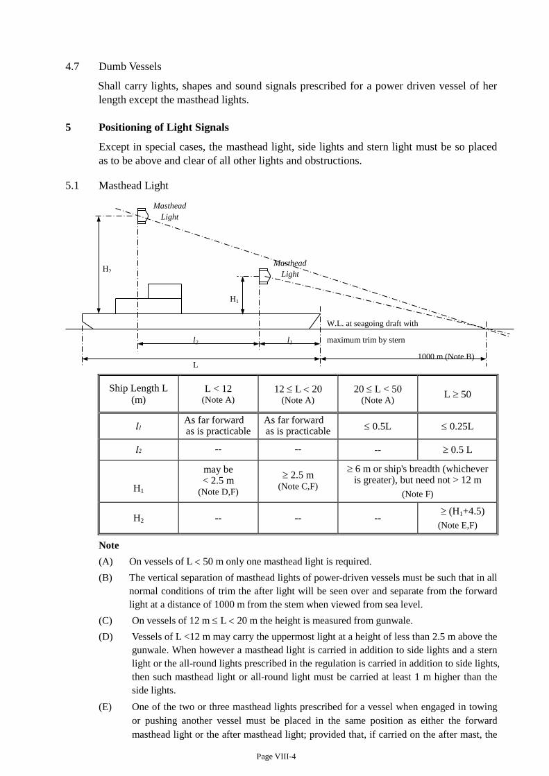
Page VIII-4
4.7 Dumb Vessels
Shall carry lights, shapes and sound signals prescribed for a power driven vessel of her length except the masthead lights.
5 Positioning of Light Signals
Except in special cases, the masthead light, side lights and stern light must be so placed as to be above and clear of all other lights and obstructions.
5.1 Masthead Light
Ship Length L (m)
L < 12 (Note A)
12 ≤ L < 20 (Note A)
20 ≤ L < 50 (Note A)
L ≥ 50
l1 As far forward as is practicable
As far forward as is practicable ≤ 0.5L ≤ 0.25L
l2 -- -- -- ≥ 0.5 L
H1
may be < 2.5 m
(Note D,F)
≥ 2.5 m (Note C,F)
≥ 6 m or ship's breadth (whichever is greater), but need not > 12 m
(Note F)
H2 -- -- -- ≥ (H1+4.5)
(Note E,F)
Note (A) On vessels of L < 50 m only one masthead light is required. (B) The vertical separation of masthead lights of power-driven vessels must be such that in all
normal conditions of trim the after light will be seen over and separate from the forward light at a distance of 1000 m from the stem when viewed from sea level.
(C) On vessels of 12 m ≤ L < 20 m the height is measured from gunwale. (D) Vessels of L <12 m may carry the uppermost light at a height of less than 2.5 m above the
gunwale. When however a masthead light is carried in addition to side lights and a stern light or the all-round lights prescribed in the regulation is carried in addition to side lights, then such masthead light or all-round light must be carried at least 1 m higher than the side lights.
(E) One of the two or three masthead lights prescribed for a vessel when engaged in towing or pushing another vessel must be placed in the same position as either the forward masthead light or the after masthead light; provided that, if carried on the after mast, the
W.L. at seagoing draft with
maximum trim by stern l2 l1
L 1000 m (Note B)
H2
H1
Masthead Light
Masthead Light
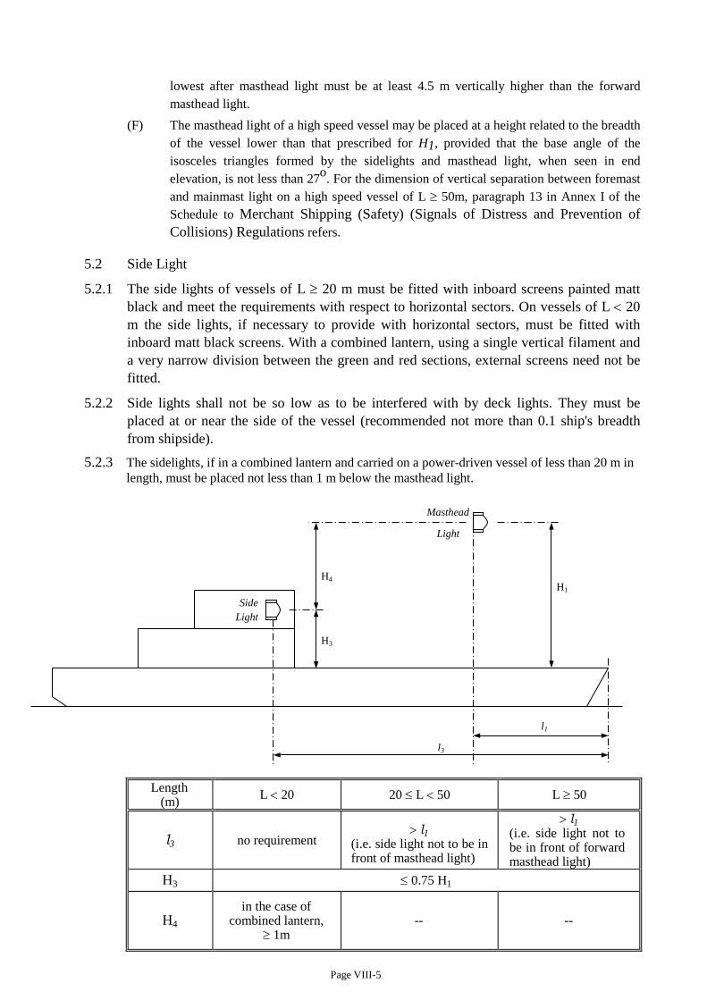
Page VIII-5
lowest after masthead light must be at least 4.5 m vertically higher than the forward masthead light.
(F) The masthead light of a high speed vessel may be placed at a height related to the breadth of the vessel lower than that prescribed for H1, provided that the base angle of the isosceles triangles formed by the sidelights and masthead light, when seen in end elevation, is not less than 27o. For the dimension of vertical separation between foremast and mainmast light on a high speed vessel of L ≥ 50m, paragraph 13 in Annex I of the Schedule to Merchant Shipping (Safety) (Signals of Distress and Prevention of Collisions) Regulations refers.
5.2 Side Light
5.2.1 The side lights of vessels of L ≥ 20 m must be fitted with inboard screens painted matt black and meet the requirements with respect to horizontal sectors. On vessels of L < 20 m the side lights, if necessary to provide with horizontal sectors, must be fitted with inboard matt black screens. With a combined lantern, using a single vertical filament and a very narrow division between the green and red sections, external screens need not be fitted.
5.2.2 Side lights shall not be so low as to be interfered with by deck lights. They must be placed at or near the side of the vessel (recommended not more than 0.1 ship's breadth from shipside).
5.2.3 The sidelights, if in a combined lantern and carried on a power-driven vessel of less than 20 m in length, must be placed not less than 1 m below the masthead light.
Length (m) L < 20 20 ≤ L < 50 L ≥ 50
l3 no requirement > l1
(i.e. side light not to be in front of masthead light)
> l1 (i.e. side light not to be in front of forward masthead light)
H3 ≤ 0.75 H1
H4 in the case of
combined lantern, ≥ 1m
-- --
l3
l1
H3
Side Light
H4 H1
Masthead
Light
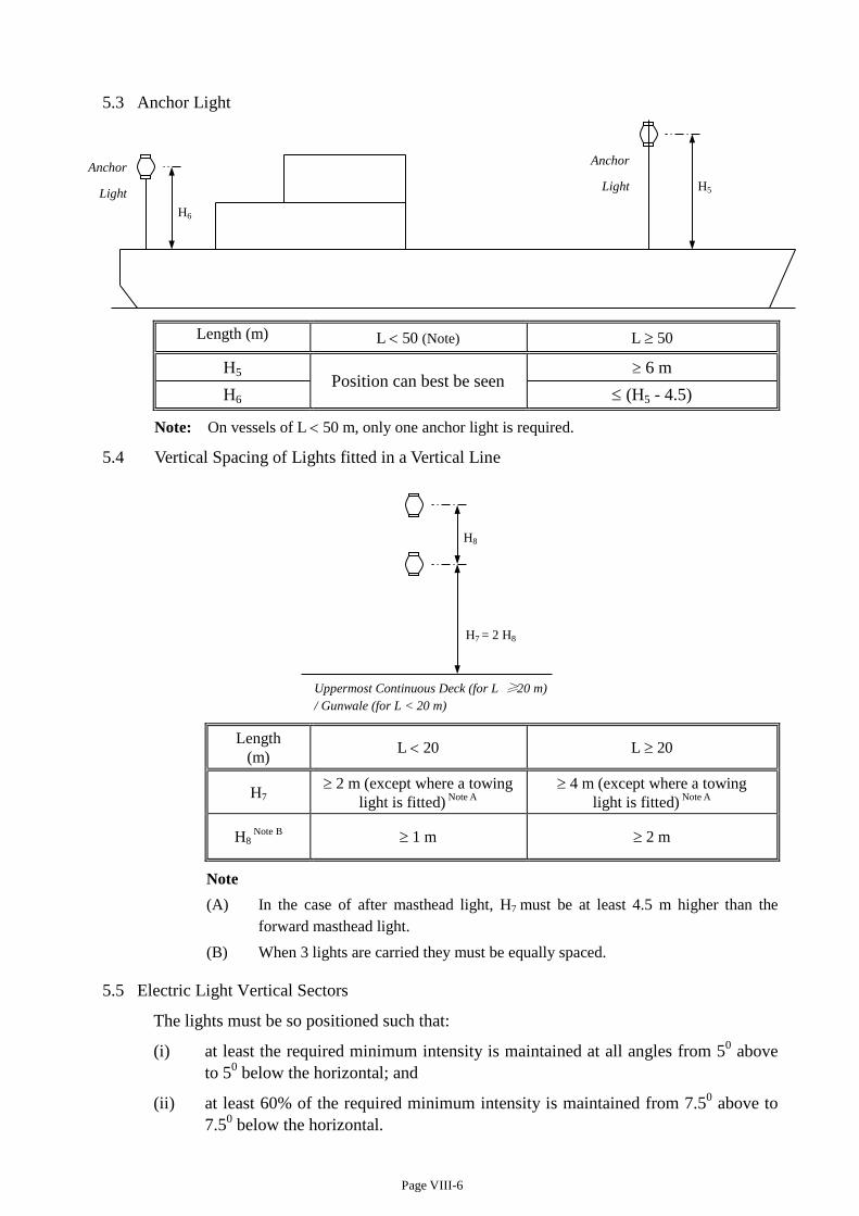
Page VIII-6
5.3 Anchor Light
Length (m) L < 50 (Note) L ≥ 50
H5 Position can best be seen ≥ 6 m
H6 ≤ (H5 - 4.5)
Note: On vessels of L < 50 m, only one anchor light is required.
5.4 Vertical Spacing of Lights fitted in a Vertical Line
Length
(m) L < 20 L ≥ 20
H7 ≥ 2 m (except where a towing
light is fitted) Note A ≥ 4 m (except where a towing
light is fitted) Note A
H8 Note B
≥ 1 m ≥ 2 m
Note (A) In the case of after masthead light, H7 must be at least 4.5 m higher than the
forward masthead light. (B) When 3 lights are carried they must be equally spaced.
5.5 Electric Light Vertical Sectors
The lights must be so positioned such that:
(i) at least the required minimum intensity is maintained at all angles from 50 above to 50 below the horizontal; and
(ii) at least 60% of the required minimum intensity is maintained from 7.50 above to 7.50 below the horizontal.
H5
H6
Anchor
Light Anchor
Light
Uppermost Continuous Deck (for L ≥ 20 m) / Gunwale (for L < 20 m)
H8
H7 = 2 H8
CODE OF PRACTICE ----
Safety Standards for Class III Vessels
(issued under Section 8 of the Merchant Shipping (Local Vessels) Ordinance, Cap 548) Local Vessels Safety Section Marine Department, HKSAR (June 2017 Edition)
Page II-1
CHAPTER II
SURVEY / INSPECTION, ISSUANCE OF CERTIFICATE AND PLAN APPROVAL
1 Survey / Inspection for Issue or Endorsement of Certificate
1.1 Any local vessel to which sections 7(1) and (3) of Survey Regulation apply when applying for an initial licence is subject to the approval of plans per items (appropriate according to category and type of vessel) indicated in Table 5-1.
1.2 Any local vessel to which Part 4 of Survey Regulation applies when applying for an initial licence is subject to the initial survey per items (appropriate according to category and type of vessel) indicated in Tables 7-1 and 7-3; and after licencing the periodical survey per items indicated in Tables 7-2 and 7-3.
1.3 Any licensed vessel of the above sections 1.1 or 1.2 intended for alteration shall be subject to the approval of plans (if section 1.1 is applicable) and survey relating to the alteration under section 76(5) of the Survey Regulation.
1.4 Outboard open sampans (P4) and fishing sampans if meeting the requirements prescribed in sections (a) and (b) respectively of Schedule 2 of the Survey Regulation are exempted from plan approval and survey.
1.5 A laid-up vessel (which is granted with a permission for laid-up) shall be subject to survey when returning to service if the Certificate of Survey previously issued has expired. If the expiry is not exceeding 2 years, the survey shall cover items due in the past 2 years as the vessel was not laid up.
1.6 Any vessel having its Certificate of Survey expired for more than 2 year but less than 8 years, the surveys shall follow the quadrennial survey programme prescribed in Table 7-2.
1.7 Any vessel having its Certificate of Survey expired for more than 8 years, it shall be subject to thorough inspection according to items of Table 7-1. If alterations had been carried out onboard vessel plans relating to the alterations shall be submitted for approval. The survey and plan approval are to comply with standards applicable to existing vessels, and the amended (if any).
1.8 When deemed necessary or at his discretion, the attending surveyor/inspector may request any other item to be presented for inspection
1.9 The Director may, on the certificate of ownership of a certificated Class III vessel, make an endorsement to the effect that the certificated vessel may be used with one or more ancillary vessels where each ancillary vessel meeting the following conditions: –
(a) belongs to the same owner as the certificated vessel;
(b) does not exceed 4 metres in length overall; and
(c) is not fitted with an engine.
2 Statutory Surveys and Application
2.1 Subject to the below section 2.2 officers delegated by the Director are responsible for the statutory plan approval and survey of vessel.
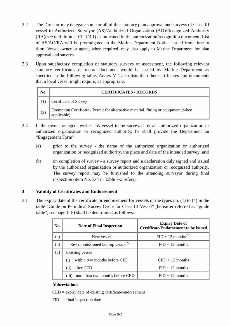
Page II-2
2.2 The Director may delegate some or all of the statutory plan approval and surveys of Class III vessel to Authorized Surveyor (AS)/Authorized Organization (AO)/Recognized Authority (RA)(see definition at Ch. I/3.1) as indicated in the authorization/recognition document. List of AS/AO/RA will be promulgated in the Marine Department Notice issued from time to time. Vessel owner or agent, when required, may also apply to Marine Department for plan approval and surveys.
2.3 Upon satisfactory completion of statutory surveys or assessment, the following relevant statutory certificates or record document would be issued by Marine Department as specified in the following table. Annex V-4 also lists the other certificates and documents that a local vessel might require, as appropriate:
No. CERTIFICATES / RECORDS
(1) Certificate of Survey
(2) Exemption Certificate / Permit for alternative material, fitting or equipment (when applicable)
2.4 If the owner or agent wishes his vessel to be surveyed by an authorized organization or authorized organization or recognized authority, he shall provide the Department an “Engagement Form”:
(a) prior to the survey - the name of the authorized organization or authorized organization or recognized authority, the place and date of the intended survey; and
(b) on completion of survey - a survey report and a declaration duly signed and issued by the authorized organization or authorized organization or recognized authority. The survey report may be furnished to the attending surveyor during final inspection (item No. E-4 in Table 7-3 refers).
3 Validity of Certificates and Endorsement
3.1 The expiry date of the certificate or endorsement for vessels of the types no. (1) to (4) in the table “Guide on Periodical Survey Cycle for Class III Vessel” (hereafter referred as “guide table”, see page II-8) shall be determined as follows:
No. Date of Final Inspection Expiry Date of Certificate/Endorsement to be issued
(a) New vessel FID + 12 months(*1)
(b) Re-commissioned laid-up vessel(*2) FID + 12 months
(c) Existing vessel
(i) within two months before CED CED + 12 months
(ii) after CED FID + 12 months
(iii) more than two months before CED FID + 12 months
Abbreviations
CED = expiry date of existing certificate/endorsement
FID = final inspection date
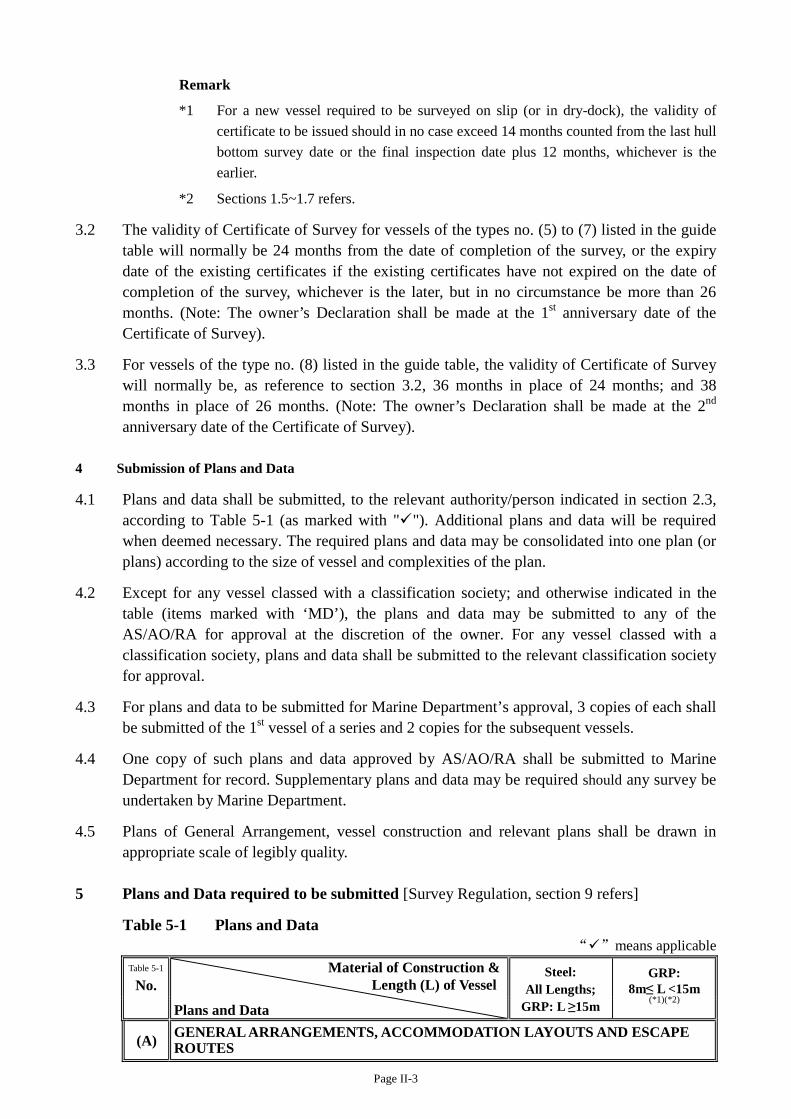
Page II-3
Remark
*1 For a new vessel required to be surveyed on slip (or in dry-dock), the validity of certificate to be issued should in no case exceed 14 months counted from the last hull bottom survey date or the final inspection date plus 12 months, whichever is the earlier.
*2 Sections 1.5~1.7 refers.
3.2 The validity of Certificate of Survey for vessels of the types no. (5) to (7) listed in the guide table will normally be 24 months from the date of completion of the survey, or the expiry date of the existing certificates if the existing certificates have not expired on the date of completion of the survey, whichever is the later, but in no circumstance be more than 26 months. (Note: The owner’s Declaration shall be made at the 1st anniversary date of the Certificate of Survey).
3.3 For vessels of the type no. (8) listed in the guide table, the validity of Certificate of Survey will normally be, as reference to section 3.2, 36 months in place of 24 months; and 38 months in place of 26 months. (Note: The owner’s Declaration shall be made at the 2nd anniversary date of the Certificate of Survey).
4 Submission of Plans and Data
4.1 Plans and data shall be submitted, to the relevant authority/person indicated in section 2.3, according to Table 5-1 (as marked with ""). Additional plans and data will be required when deemed necessary. The required plans and data may be consolidated into one plan (or plans) according to the size of vessel and complexities of the plan.
4.2 Except for any vessel classed with a classification society; and otherwise indicated in the table (items marked with ‘MD’), the plans and data may be submitted to any of the AS/AO/RA for approval at the discretion of the owner. For any vessel classed with a classification society, plans and data shall be submitted to the relevant classification society for approval.
4.3 For plans and data to be submitted for Marine Department’s approval, 3 copies of each shall be submitted of the 1st vessel of a series and 2 copies for the subsequent vessels.
4.4 One copy of such plans and data approved by AS/AO/RA shall be submitted to Marine Department for record. Supplementary plans and data may be required should any survey be undertaken by Marine Department.
4.5 Plans of General Arrangement, vessel construction and relevant plans shall be drawn in appropriate scale of legibly quality.
5 Plans and Data required to be submitted [Survey Regulation, section 9 refers]
Table 5-1 Plans and Data “”means applicable
Table 5-1
No. Material of Construction &
Length (L) of Vessel
Plans and Data
Steel: All Lengths;
GRP: L ≥15m
GRP: 8m≤ L <15m
(*1)(*2)
(A) GENERAL ARRANGEMENTS, ACCOMMODATION LAYOUTS AND ESCAPE ROUTES
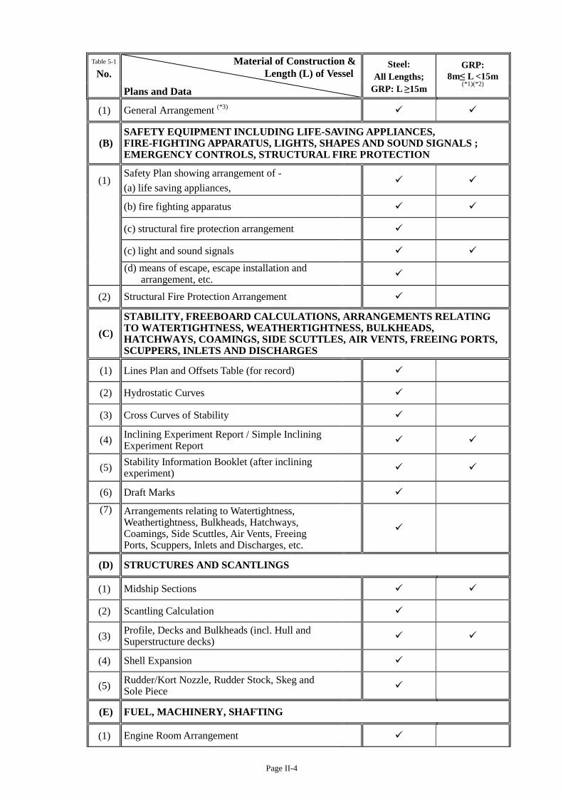
Page II-4
Table 5-1
No. Material of Construction &
Length (L) of Vessel
Plans and Data
Steel: All Lengths;
GRP: L ≥15m
GRP: 8m≤ L <15m
(*1)(*2)
(1) General Arrangement (*3)
(B) SAFETY EQUIPMENT INCLUDING LIFE-SAVING APPLIANCES, FIRE-FIGHTING APPARATUS, LIGHTS, SHAPES AND SOUND SIGNALS ; EMERGENCY CONTROLS, STRUCTURAL FIRE PROTECTION
(1) Safety Plan showing arrangement of - (a) life saving appliances,
(b) fire fighting apparatus
(c) structural fire protection arrangement
(c) light and sound signals
(d) means of escape, escape installation and arrangement, etc.
(2) Structural Fire Protection Arrangement
(C) STABILITY, FREEBOARD CALCULATIONS, ARRANGEMENTS RELATING TO WATERTIGHTNESS, WEATHERTIGHTNESS, BULKHEADS, HATCHWAYS, COAMINGS, SIDE SCUTTLES, AIR VENTS, FREEING PORTS, SCUPPERS, INLETS AND DISCHARGES
(1) Lines Plan and Offsets Table (for record)
(2) Hydrostatic Curves
(3) Cross Curves of Stability
(4) Inclining Experiment Report / Simple Inclining Experiment Report
(5) Stability Information Booklet (after inclining experiment)
(6) Draft Marks (7) Arrangements relating to Watertightness,
Weathertightness, Bulkheads, Hatchways, Coamings, Side Scuttles, Air Vents, Freeing Ports, Scuppers, Inlets and Discharges, etc.
(D) STRUCTURES AND SCANTLINGS
(1) Midship Sections
(2) Scantling Calculation
(3) Profile, Decks and Bulkheads (incl. Hull and Superstructure decks)
(4) Shell Expansion
(5) Rudder/Kort Nozzle, Rudder Stock, Skeg and Sole Piece
(E) FUEL, MACHINERY, SHAFTING
(1) Engine Room Arrangement
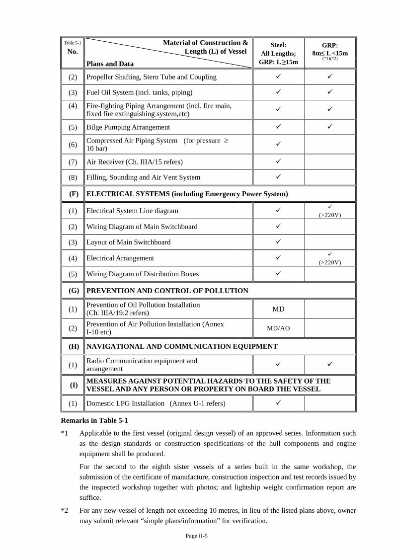
Page II-5
Table 5-1
No. Material of Construction &
Length (L) of Vessel
Plans and Data
Steel: All Lengths;
GRP: L ≥15m
GRP: 8m≤ L <15m
(*1)(*2)
(2) Propeller Shafting, Stern Tube and Coupling
(3) Fuel Oil System (incl. tanks, piping)
(4) Fire-fighting Piping Arrangement (incl. fire main, fixed fire extinguishing system,etc)
(5) Bilge Pumping Arrangement
(6) Compressed Air Piping System (for pressure ≥ 10 bar)
(7) Air Receiver (Ch. IIIA/15 refers)
(8) Filling, Sounding and Air Vent System
(F) ELECTRICAL SYSTEMS (including Emergency Power System)
(1) Electrical System Line diagram (>220V)
(2) Wiring Diagram of Main Switchboard
(3) Layout of Main Switchboard
(4) Electrical Arrangement (>220V)
(5) Wiring Diagram of Distribution Boxes
(G) PREVENTION AND CONTROL OF POLLUTION
(1) Prevention of Oil Pollution Installation (Ch. IIIA/19.2 refers)
MD
(2) Prevention of Air Pollution Installation (Annex I-10 etc) MD/AO
(H) NAVIGATIONAL AND COMMUNICATION EQUIPMENT
(1) Radio Communication equipment and arrangement
(I) MEASURES AGAINST POTENTIAL HAZARDS TO THE SAFETY OF THE VESSEL AND ANY PERSON OR PROPERTY ON BOARD THE VESSEL
(1) Domestic LPG Installation (Annex U-1 refers)
Remarks in Table 5-1
*1 Applicable to the first vessel (original design vessel) of an approved series. Information such as the design standards or construction specifications of the hull components and engine equipment shall be produced.
For the second to the eighth sister vessels of a series built in the same workshop, the submission of the certificate of manufacture, construction inspection and test records issued by the inspected workshop together with photos; and lightship weight confirmation report are suffice.
*2 For any new vessel of length not exceeding 10 metres, in lieu of the listed plans above, owner may submit relevant “simple plans/information” for verification.
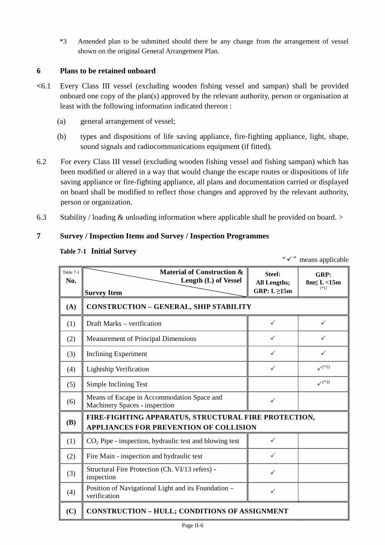
Page II-6
*3 Amended plan to be submitted should there be any change from the arrangement of vessel shown on the original General Arrangement Plan.
6 Plans to be retained onboard
<6.1 Every Class III vessel (excluding wooden fishing vessel and sampan) shall be provided onboard one copy of the plan(s) approved by the relevant authority, person or organisation at least with the following information indicated thereon :
(a) general arrangement of vessel;
(b) types and dispositions of life saving appliance, fire-fighting appliance, light, shape, sound signals and radiocommunications equipment (if fitted).
6.2 For every Class III vessel (excluding wooden fishing vessel and fishing sampan) which has been modified or altered in a way that would change the escape routes or dispositions of life saving appliance or fire-fighting appliance, all plans and documentation carried or displayed on board shall be modified to reflect those changes and approved by the relevant authority, person or organization.
6.3 Stability / loading & unloading information where applicable shall be provided on board. > 7 Survey / Inspection Items and Survey / Inspection Programmes
Table 7-1 Initial Survey “”means applicable
Table 7-1
No. Material of Construction &
Length (L) of Vessel
Survey Item
Steel: All Lengths;
GRP: L ≥15m
GRP: 8m≤ L <15m
(*1)
(A) CONSTRUCTION – GENERAL, SHIP STABILITY
(1) Draft Marks – verification
(2) Measurement of Principal Dimensions
(3) Inclining Experiment
(4) Lightship Verification (*2)
(5) Simple Inclining Test (*3)
(6) Means of Escape in Accommodation Space and Machinery Spaces - inspection
(B) FIRE-FIGHTING APPARATUS, STRUCTURAL FIRE PROTECTION, APPLIANCES FOR PREVENTION OF COLLISION
(1) CO2 Pipe - inspection, hydraulic test and blowing test
(2) Fire Main - inspection and hydraulic test
(3) Structural Fire Protection (Ch. VI/13 refers) - inspection
(4) Position of Navigational Light and its Foundation – verification
(C) CONSTRUCTION – HULL; CONDITIONS OF ASSIGNMENT
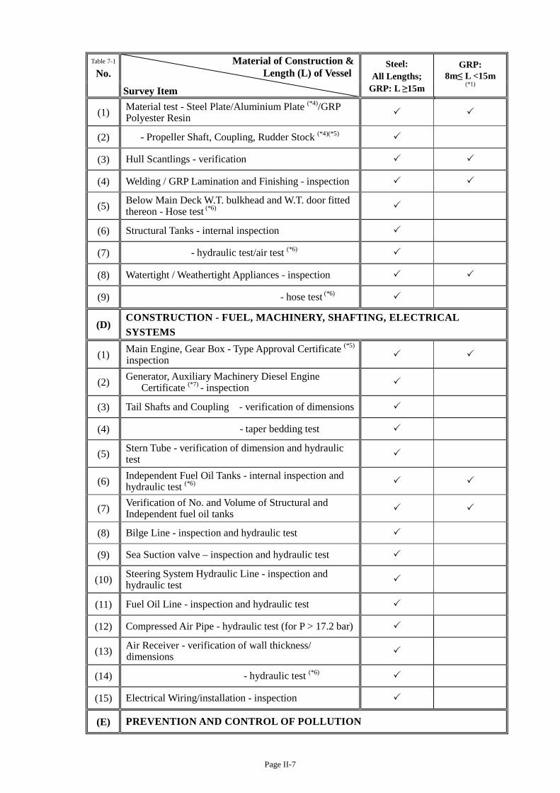
Page II-7
Table 7-1
No. Material of Construction &
Length (L) of Vessel
Survey Item
Steel: All Lengths;
GRP: L ≥15m
GRP: 8m≤ L <15m
(*1)
(1) Material test - Steel Plate/Aluminium Plate (*4)/GRP Polyester Resin
(2) - Propeller Shaft, Coupling, Rudder Stock (*4)(*5)
(3) Hull Scantlings - verification
(4) Welding / GRP Lamination and Finishing - inspection
(5) Below Main Deck W.T. bulkhead and W.T. door fitted thereon - Hose test (*6)
(6) Structural Tanks - internal inspection
(7) - hydraulic test/air test (*6)
(8) Watertight / Weathertight Appliances - inspection
(9) - hose test (*6)
(D) CONSTRUCTION - FUEL, MACHINERY, SHAFTING, ELECTRICAL SYSTEMS
(1) Main Engine, Gear Box - Type Approval Certificate (*5) inspection
(2) Generator, Auxiliary Machinery Diesel Engine Certificate (*7) - inspection
(3) Tail Shafts and Coupling - verification of dimensions
(4) - taper bedding test
(5) Stern Tube - verification of dimension and hydraulic test
(6) Independent Fuel Oil Tanks - internal inspection and hydraulic test (*6)
(7) Verification of No. and Volume of Structural and Independent fuel oil tanks
(8) Bilge Line - inspection and hydraulic test
(9) Sea Suction valve – inspection and hydraulic test
(10) Steering System Hydraulic Line - inspection and hydraulic test
(11) Fuel Oil Line - inspection and hydraulic test
(12) Compressed Air Pipe - hydraulic test (for P > 17.2 bar)
(13) Air Receiver - verification of wall thickness/ dimensions
(14) - hydraulic test (*6)
(15) Electrical Wiring/installation - inspection
(E) PREVENTION AND CONTROL OF POLLUTION

Page II-8
Table 7-1
No. Material of Construction &
Length (L) of Vessel
Survey Item
Steel: All Lengths;
GRP: L ≥15m
GRP: 8m≤ L <15m
(*1)
(1) Prevention of Oil Pollution Installation (MD/AO) - Inspection
(2) - hydraulic test of independent bilge water / sludge holding tank
Remarks in Table 7-1
*1 Except otherwise indicated, the listed items are applicable to the first vessel (original design vessel) of an approved series of 8m≤ L<15m. The workshop and relating facilities shall be inspected by Marine Department.
For the second to the eighth sister vessels of a series built in the same workshop, the submission of the certificate of manufacture, construction inspection and test records issued by the inspected workshop together with photos are suffice.
*2 Applicable to the 2nd to 8th of a series of 8 sister vessels of 10m≤ L<15m.
*3 For new vessels of length not exceeding 10 metres and only operating in Hong Kong waters.
*4 In lieu of the material test, mill sheet issued/endorsed by a classification society is acceptable.
*5 Ch. IIIA/9 and IIIA/17.4 refer.
*6 Annex M/3, 4 refer. Hose test for door fitted on watertight bulkhead may be replaced by a chalk test if a prototype test (with pressure corresponding at least to the head required for the intended location) has been carried out and certificated.
*7 Ch. IIIA/7.1 refers. For new vessels, (i) maker certificate for petrol engine; (ii) for diesel engine maker or classification societies approved certificates / information and document as appropriate required in Ch. IIIA or IIIB and Annex I-10 of this Code or MARPOL Annex VI.
Guide on Periodical Survey Cycle for Class III Vessel (“guide table”)
No. Material of
Construction Vessel Length
(L)(metres)
Owner Declaration
(*1)
Yearly Interval of Survey on
Slip (*2) (Table 7-2 refers)
Interval of Survey Afloat
(Table 7-3 refers)
(1) Steel L ≥ 24 - 2 Annual
(2) Steel L < 24 - 3 Annual
(3) GRP L ≥ 24 - 2 Annual
(4) GRP 15 ≤ L < 24 - 3 Annual
(5) GRP 8 ≤ L <15 Annual - 2
(6) GRP L < 8 Annual - 2
(7) Wood L ≥ 8 Annual - 2
(8) Wood L < 8 Annual - 3
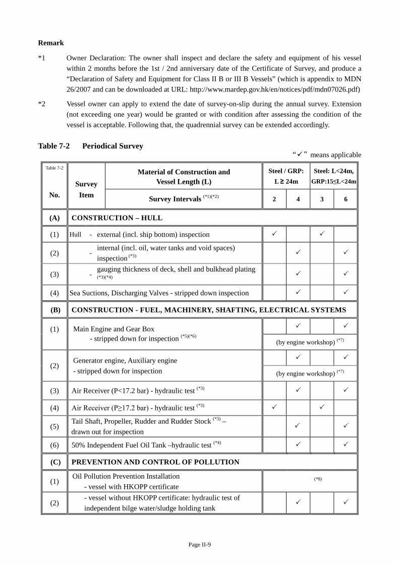
Page II-9
Remark
*1 Owner Declaration: The owner shall inspect and declare the safety and equipment of his vessel within 2 months before the 1st / 2nd anniversary date of the Certificate of Survey, and produce a “Declaration of Safety and Equipment for Class II B or III B Vessels” (which is appendix to MDN 26/2007 and can be downloaded at URL: http://www.mardep.gov.hk/en/notices/pdf/mdn07026.pdf)
*2 Vessel owner can apply to extend the date of survey-on-slip during the annual survey. Extension (not exceeding one year) would be granted or with condition after assessing the condition of the vessel is acceptable. Following that, the quadrennial survey can be extended accordingly.
Table 7-2 Periodical Survey
“”means applicable
Table 7-2
Survey Material of Construction and
Vessel Length (L) Steel / GRP:
L ≥ 24m
Steel: L<24m, GRP:15≤L<24m
No. Item Survey Intervals (*1)(*2) 2 4 3 6
(A) CONSTRUCTION – HULL
(1) Hull - external (incl. ship bottom) inspection
(2) - internal (incl. oil, water tanks and void spaces) inspection (*3)
(3) - gauging thickness of deck, shell and bulkhead plating (*3)(*4)
(4) Sea Suctions, Discharging Valves - stripped down inspection
(B) CONSTRUCTION - FUEL, MACHINERY, SHAFTING, ELECTRICAL SYSTEMS
(1)
Main Engine and Gear Box - stripped down for inspection (*5)(*6)
(by engine workshop) (*7)
(2) Generator engine, Auxiliary engine - stripped down for inspection
(by engine workshop) (*7)
(3) Air Receiver (P<17.2 bar) - hydraulic test (*3)
(4) Air Receiver (P≥17.2 bar) - hydraulic test (*3)
(5) Tail Shaft, Propeller, Rudder and Rudder Stock (*3) – drawn out for inspection
(6) 50% Independent Fuel Oil Tank –hydraulic test (*4)
(C) PREVENTION AND CONTROL OF POLLUTION
(1) Oil Pollution Prevention Installation
- vessel with HKOPP certificate (*8)
(2) - vessel without HKOPP certificate: hydraulic test of
independent bilge water/sludge holding tank
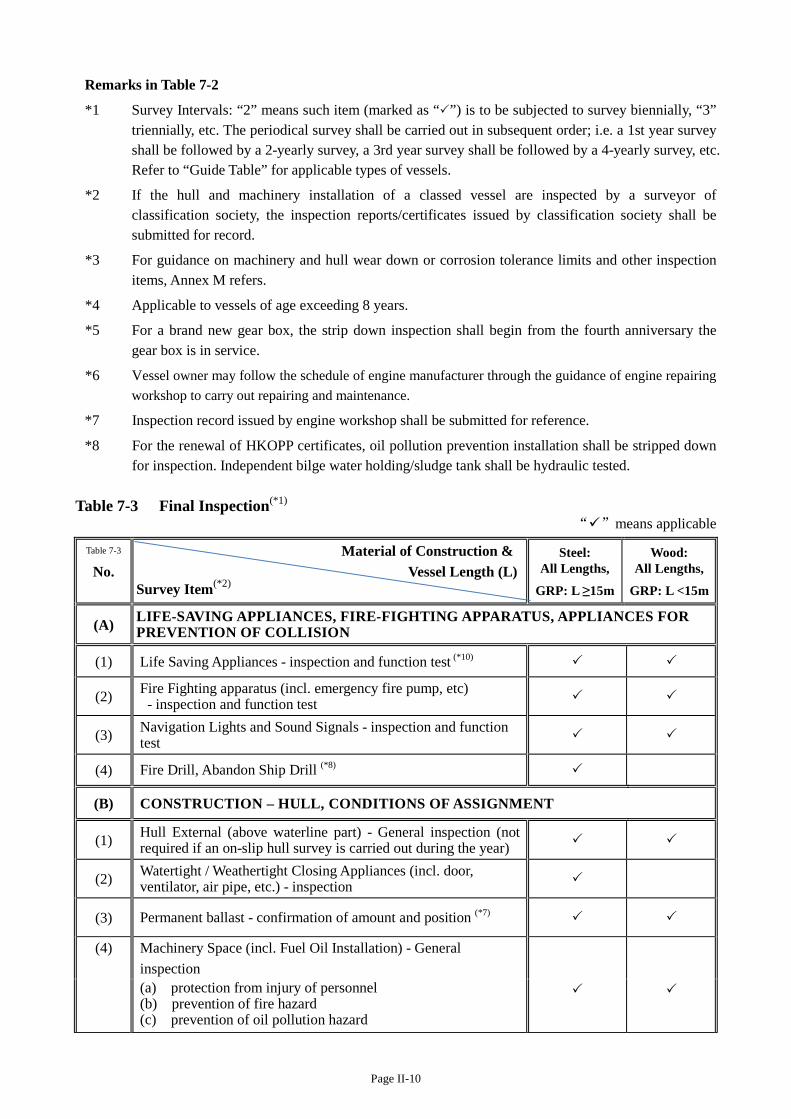
Page II-10
Remarks in Table 7-2
*1 Survey Intervals: “2” means such item (marked as “”) is to be subjected to survey biennially, “3” triennially, etc. The periodical survey shall be carried out in subsequent order; i.e. a 1st year survey shall be followed by a 2-yearly survey, a 3rd year survey shall be followed by a 4-yearly survey, etc. Refer to “Guide Table” for applicable types of vessels.
*2 If the hull and machinery installation of a classed vessel are inspected by a surveyor of classification society, the inspection reports/certificates issued by classification society shall be submitted for record.
*3 For guidance on machinery and hull wear down or corrosion tolerance limits and other inspection items, Annex M refers.
*4 Applicable to vessels of age exceeding 8 years.
*5 For a brand new gear box, the strip down inspection shall begin from the fourth anniversary the gear box is in service.
*6 Vessel owner may follow the schedule of engine manufacturer through the guidance of engine repairing workshop to carry out repairing and maintenance.
*7 Inspection record issued by engine workshop shall be submitted for reference.
*8 For the renewal of HKOPP certificates, oil pollution prevention installation shall be stripped down for inspection. Independent bilge water holding/sludge tank shall be hydraulic tested.
Table 7-3 Final Inspection(*1)
“”means applicable
Table 7-3
No. Material of Construction &
Vessel Length (L) Survey Item(*2)
Steel: All Lengths,
GRP: L ≥15m
Wood: All Lengths,
GRP: L <15m
(A) LIFE-SAVING APPLIANCES, FIRE-FIGHTING APPARATUS, APPLIANCES FOR PREVENTION OF COLLISION
(1) Life Saving Appliances - inspection and function test (*10)
(2) Fire Fighting apparatus (incl. emergency fire pump, etc) - inspection and function test
(3) Navigation Lights and Sound Signals - inspection and function test
(4) Fire Drill, Abandon Ship Drill (*8)
(B) CONSTRUCTION – HULL, CONDITIONS OF ASSIGNMENT
(1) Hull External (above waterline part) - General inspection (not required if an on-slip hull survey is carried out during the year)
(2) Watertight / Weathertight Closing Appliances (incl. door, ventilator, air pipe, etc.) - inspection
(3) Permanent ballast - confirmation of amount and position (*7)
(4)
Machinery Space (incl. Fuel Oil Installation) - General inspection
(a) protection from injury of personnel (b) prevention of fire hazard (c) prevention of oil pollution hazard

Page II-11
Table 7-3
No. Material of Construction &
Vessel Length (L) Survey Item(*2)
Steel: All Lengths,
GRP: L ≥15m
Wood: All Lengths,
GRP: L <15m
(5) Principal Dimensions, Engine and major machinery particulars - verification
(C) CONSTRUCTION - FUEL, MACHINERY, SHAFTING, ELECTRICAL SYSTEMS
(1) Main Engines, Generator Engines, Steering Gears - running test
(2) Unattended Machinery Space Installation (Ch. IIIA/18 and IIIB/13 refer) - function test
(3) Air Receiver Safety Valves - function test
(4) Bilge and Oily Water Pumping System - function test
(5) Electrical Circuit - earthing test
(6) - insulation resistance test (*4)
(7) - Main circuit breaker function test (*5)
(8) Location of emergency source of electrical power shall be outside machinery space and above waterline – verification (*6)
(9) Meters on Switchboard - function test
(D) PREVENTION AND CONTROL OF POLLUTION
(1) Air Emission Assessment (*3)
(2) Prevention of Oil Pollution Installation - function test
(E) NAVIGATIONAL, COMMUNICATION EQUIPMENTAND OTHERS
(1) Radio Communication Equipment
(2) Verifying Certificates of Competency of Master and Engineer (if manoeuvring test required)
(3) Plans and data required to be retained onboard (section 6.1 refers) - confirmation of numbers and contents (*9)
(4) Survey report issued by AS/AO/RA - verification
(5) Inspection of remedial deficiency items in Initial / Periodical Survey
(6) Domestic L.P.G. Installation - inspection
Remarks in Table 7-3
*1 For intervals of final inspection with respect to type of vessel, Guide Table refers.
*2 Where practicable the listed items may be presented for inspection prior to the final inspection.
*3 Air emission requirements to be conducted as per Annex I-10.
*4 Megger tests report to be submitted for record (insulation resistance shall not be less than 1 MΩ). A valid EMSD registered electrical contractor (REC) issued electrical system insulation test report (with the test being conducted by an EMSD registered electrical worker (REW) within 2 weeks prior to the final inspection) is acceptable in lieu of the insulation resistance test inspection responsible by MD officer or authorized inspection personnels. A valid electrical system insulation

Page II-12
test report shall include the relevant necessary information. A valid electrical system insulation test report issued by an authorized inspection personnel is acceptable. A valid electrical system insulation test report issued by an authorized inspection personnel is acceptable.
*5 Applicable to any vessel fitted with A.C. generator of each capacity exceeding 50 kW.
*6 Applicable to only a vessel which is still a new vessel when the reference to “the commencement date of the Survey Regulation” in the definition of “new vessel” under Ch. I/3.1 is substituted by “29 November 2014”.
*7 In addition to the visual inspection, owner’s declaration on the amount and disposition of the ballast weights to be furnished to Marine Department for record.
*8 Applicable to vessels plying beyond Hong Kong waters.
*9 Excluding wooden fishing vessel and sampan.
*10 Random checks on lifejackets are to be according to the following proportions:
Statutorily Required No. of Lifejackets
Random Check
1-10 100%
11-100 10 pieces
The counting of the number is to be 100%.
Page IIIA-1
CHAPTER III A
HULL CONSTRUCTION, MACHINERY, ELECTRICAL INSTALLATIONS
AND FITTINGS - CATEGORY A VESSEL
PART 1 GENERAL REQUIREMENTS
(1) Except as otherwise specified, every vessel shall be designed and built to the
requirements of rules and regulations of a classification society as listed at Annex
A, having regard the size, construction material, and operational services of the
vessel. Such rules and regulations shall be complied with in its entirety. However
in the case of any inconsistency between this Code and any of the requirements of
the classification society rules, the requirements of this Code shall be complied
with.
(2) Main propulsion, control, fuel oil, compressed air, electrical and refrigeration
systems; generator machinery; air receivers and other pressure equipment; piping
and pumping arrangements; steering equipment, shafts and couplings for power
transmission shall be designed, constructed and tested to the satisfaction of the
surveyor. Suitable means or device shall be provided to machinery, equipment,
lifting gear, winches, fish handling and fish processing equipment, etc. so as to
reduce to a minimum any danger to persons on board. Special attention shall be
paid to moving parts, hot surfaces and other potential dangers.
PART 2 HULL CONSTRUCTION
1 Main Deck Construction
1.1 Every vessel shall be fully decked.
1.2 For a new vesselNote1
, if opening is fitted on main deck leading to spaces below deck the
first tier of superstructure on main deck shall be of weathertight construction for the
purpose of maintaining the integrity and stability of vessel. The closing appliances fitted
on such position shall meet the requirements of section 3 below.
2 Bulkheads
2.1 On any motored vessel, the dispositions and construction of watertight bulkheads shall
meet the relevant requirements of classification societies.
2.2 On all vessels other than wooden vessels, and as far as practicable on wooden vessels,
bulkheads shall be of watertight construction.
2.3 Access openings fitted in watertight bulkheads shall be equipped with effective
watertight closing appliances and meet the requirements stipulated in section 2.4.
2.4 The design of the watertight doors shall comply with the following requirements:
(a) The dimension of the watertight doors shall suit the design of the vessels;
Note1
Applicable to a vessel which is a new vessel when the reference to “the commencement date” in the
definition of “new vessel” under section 2 of the Survey Regulation is substituted by “3 March
2017”.
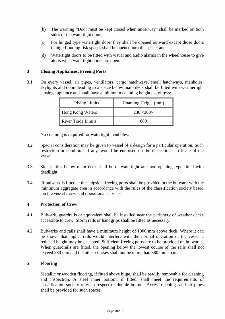
Page IIIA-2
(b) The warning “Door must be kept closed when underway” shall be marked on both
sides of the watertight door;
(c) For hinged type watertight door, they shall be opened outward except those doors
in high flooding risk spaces shall be opened into the space; and
(d) Watertight doors to be fitted with visual and audio alarms in the wheelhouse to give
alerts when watertight doors are open.
3 Closing Appliances, Freeing Ports
3.1 On every vessel, air pipes, ventilators, cargo hatchways, small hatchways, manholes,
skylights and doors leading to a space below main deck shall be fitted with weathertight
closing appliance and shall have a minimum coaming height as follows:
Plying Limits Coaming Height (mm)
Hong Kong Waters 230 <300>
River Trade Limits 600
No coaming is required for watertight manholes.
3.2 Special consideration may be given to vessel of a design for a particular operation. Such
restriction or condition, if any, would be endorsed on the inspection certificate of the
vessel.
3.3 Sidescuttles below main deck shall be of watertight and non-opening type fitted with
deadlight.
3.4 If bulwark is fitted at the shipside, freeing ports shall be provided in the bulwark with the
minimum aggregate area in accordance with the rules of the classification society based
on the vessel’s size and operational services.
4 Protection of Crew
4.1 Bulwark, guardrails or equivalent shall be installed near the periphery of weather decks
accessible to crew. Storm rails or handgrips shall be fitted as necessary.
4.2 Bulwarks and rails shall have a minimum height of 1000 mm above deck. Where it can
be shown that higher rails would interfere with the normal operation of the vessel a
reduced height may be accepted. Sufficient freeing ports are to be provided on bulwarks.
When guardrails are fitted, the opening below the lowest course of the rails shall not
exceed 230 mm and the other courses shall not be more than 380 mm apart.
5 Flooring
Metallic or wooden flooring, if fitted above bilge, shall be readily removable for cleaning
and inspection. A steel inner bottom, if fitted, shall meet the requirements of
classification society rules in respect of double bottom. Access openings and air pipes
shall be provided for such spaces.

Page IIIA-3
6 Marking of Hull
6.1 The certificate of ownership number of a vessel must be marked in accordance with
section 38 of the Merchant Shipping (Local Vessels) (Certification and Licensing)
Regulation.
6.2 Permanent draft marks shall be provided on port and starboard side of stem and stern of a
vessel. The marks shall be measured from the bottom of the keel, with letters and figures
being in decimetric heights and at two decimetric intervals.
PART 3 MACHINERY INSTALLATION
7 Main Engine, Auxiliary Engine and Gear Box
7.1 In any vessel plying beyond Hong Kong waters which is not classed with a classification
society and has main engine power output exceeding 130 kW, such main engine and its
associated gear box shall be of a type approved by a classification society or maritime
administration.
7.2 The main engine and the associated gearbox shall be matched at the maximum
continuous rating condition. Alternative rating may be accepted subject to proper
justification is given.
7.3 New main engines and gear boxes are required to be fitted on new vessels stated in
section 7.1. For vessels other than those stated in section 7.1 used engine may be fitted.
To facilitate the confirmation of the source of origin and/or the quality of reconditioning
of the used engine, proper document from the original engine maker or purchase
document from the engine workshop shall be submitted. The data on engine model, type
and identification number shall be clear and adequate for accurate assessment of the
engine power. The reconditioning reports shall give adequate details similar or same as
the items and format given on checklist of engine and gearbox inspection in Annex I-2
and I-3. For new engine requirements, owners are drawn attention to the recommendation
in Annex I-10.
Vessels built on or after 1 June 2008 but before 1 July 2016 may be fitted with Tier I
engine; vessels built on or after 1 July 2016 must be fitted with Tier II engine.
7.4 For main engine and gear box fitted on vessel other than that stated in section 7.1,
documentation provided by manufacturer indicating that the main engines are of marine
type is sufficient.
7.5 Auxiliary engine(s) on new mechanically propelled vessel shall be ‘marine type’;
auxiliary engine(s) on existing mechanically propelled vessel shall also be ‘marine type’
if they are being replaced/renewed.
7.6. Any engine fitted on a vessel shall be properly maintained at all time free from dark
smoke emission. In this regard, during the final inspection for initial and periodic survey,
engine performance condition check would include smoke emission test using
Ringelmann Chart. Shade 2 of the Ringelmann Chart and a continuous period of 3
minutes are the upper limits. The emission beyond this limit is considered as a
contravention of the law.
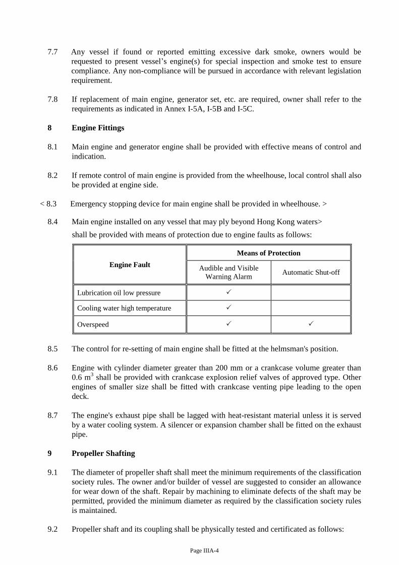
Page IIIA-4
7.7 Any vessel if found or reported emitting excessive dark smoke, owners would be
requested to present vessel’s engine(s) for special inspection and smoke test to ensure
compliance. Any non-compliance will be pursued in accordance with relevant legislation
requirement.
7.8 If replacement of main engine, generator set, etc. are required, owner shall refer to the
requirements as indicated in Annex I-5A, I-5B and I-5C.
8 Engine Fittings
8.1 Main engine and generator engine shall be provided with effective means of control and
indication.
8.2 If remote control of main engine is provided from the wheelhouse, local control shall also
be provided at engine side.
< 8.3 Emergency stopping device for main engine shall be provided in wheelhouse. >
8.4 Main engine installed on any vessel that may ply beyond Hong Kong waters>
shall be provided with means of protection due to engine faults as follows:
Engine Fault
Means of Protection
Audible and Visible
Warning Alarm Automatic Shut-off
Lubrication oil low pressure
Cooling water high temperature
Overspeed
8.5 The control for re-setting of main engine shall be fitted at the helmsman's position.
8.6 Engine with cylinder diameter greater than 200 mm or a crankcase volume greater than
0.6 m3 shall be provided with crankcase explosion relief valves of approved type. Other
engines of smaller size shall be fitted with crankcase venting pipe leading to the open
deck.
8.7 The engine's exhaust pipe shall be lagged with heat-resistant material unless it is served
by a water cooling system. A silencer or expansion chamber shall be fitted on the exhaust
pipe.
9 Propeller Shafting
9.1 The diameter of propeller shaft shall meet the minimum requirements of the classification
society rules. The owner and/or builder of vessel are suggested to consider an allowance
for wear down of the shaft. Repair by machining to eliminate defects of the shaft may be
permitted, provided the minimum diameter as required by the classification society rules
is maintained.
9.2 Propeller shaft and its coupling shall be physically tested and certificated as follows:
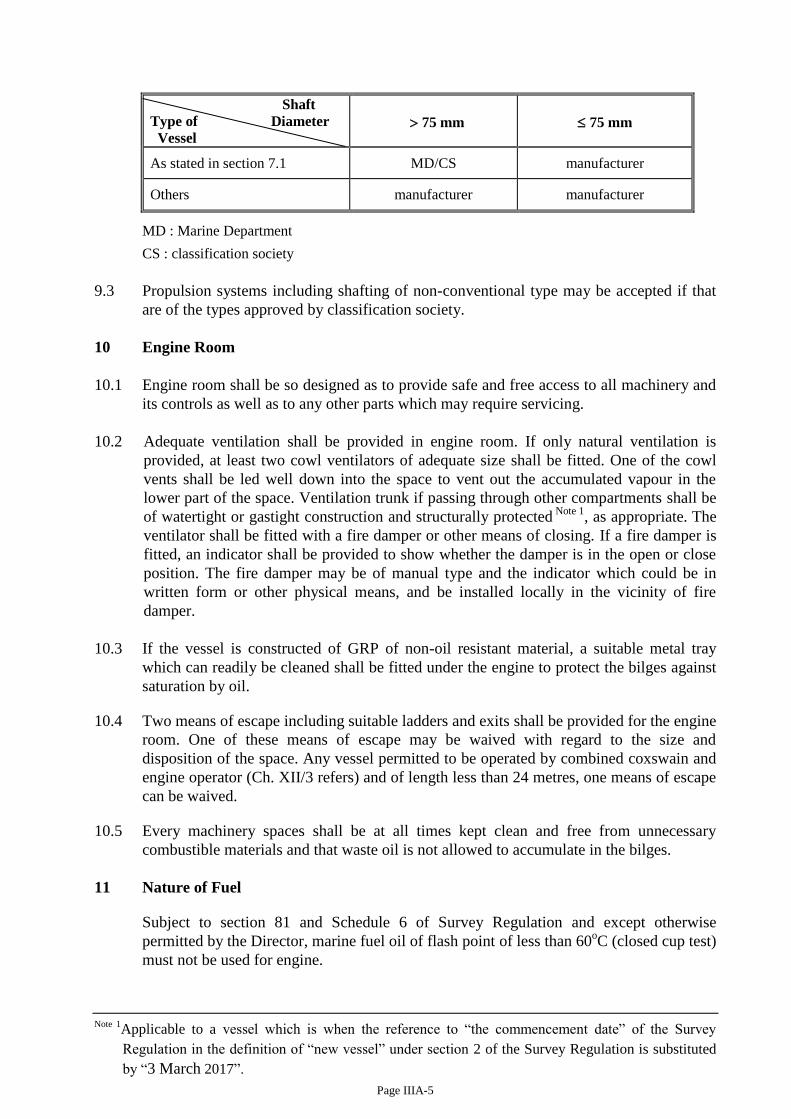
Page IIIA-5
Shaft
Type of Diameter
Vessel
75 mm
75 mm
As stated in section 7.1 MD/CS manufacturer
Others manufacturer manufacturer
MD : Marine Department
CS : classification society
9.3 Propulsion systems including shafting of non-conventional type may be accepted if that
are of the types approved by classification society.
10 Engine Room
10.1 Engine room shall be so designed as to provide safe and free access to all machinery and
its controls as well as to any other parts which may require servicing.
10.2 Adequate ventilation shall be provided in engine room. If only natural ventilation is
provided, at least two cowl ventilators of adequate size shall be fitted. One of the cowl
vents shall be led well down into the space to vent out the accumulated vapour in the
lower part of the space. Ventilation trunk if passing through other compartments shall be
of watertight or gastight construction and structurally protected Note 1
, as appropriate. The
ventilator shall be fitted with a fire damper or other means of closing. If a fire damper is
fitted, an indicator shall be provided to show whether the damper is in the open or close
position. The fire damper may be of manual type and the indicator which could be in
written form or other physical means, and be installed locally in the vicinity of fire
damper.
10.3 If the vessel is constructed of GRP of non-oil resistant material, a suitable metal tray
which can readily be cleaned shall be fitted under the engine to protect the bilges against
saturation by oil.
10.4 Two means of escape including suitable ladders and exits shall be provided for the engine
room. One of these means of escape may be waived with regard to the size and
disposition of the space. Any vessel permitted to be operated by combined coxswain and
engine operator (Ch. XII/3 refers) and of length less than 24 metres, one means of escape
can be waived.
10.5 Every machinery spaces shall be at all times kept clean and free from unnecessary
combustible materials and that waste oil is not allowed to accumulate in the bilges.
11 Nature of Fuel
Subject to section 81 and Schedule 6 of Survey Regulation and except otherwise
permitted by the Director, marine fuel oil of flash point of less than 60oC (closed cup test)
must not be used for engine.
Note 1Applicable to a vessel which is when the reference to “the commencement date” of the Survey
Regulation in the definition of “new vessel” under section 2 of the Survey Regulation is substituted
by “3 March 2017”.
Page IIIA-6
12 Tanks
12.1 The arrangements for filling fuel tanks shall be such that oil will not spill or overflow
into any compartment of the vessel. Woodwork surrounding the deck filling mouth shall
be covered with metal piece. No loose can/barrel of fuel oil shall be carried on board.
12.2 Fuel tanks shall be substantially constructed of suitable material and securely fixed in
position. The tanks and their connections shall be tested per the requirements of Annex
M/3.1.
13 Pumping and Piping Arrangement
13.1 All fuel oil tank, lubrication oil tank and spaces where flammable gas may collect shall
be fitted with venting pipes leading to the weather deck. The open end of any oil tank's
venting pipe shall be fitted with properly secured metallic wire-gauze.
13.2 Safe and efficient means of ascertaining the amount of fuel oil in any oil tank shall be
provided. For sounding pipes, their upper ends shall terminate in safe positions and be
fitted with suitable means of closure. Any transparent level gauge shall be of robust
construction and of a type acceptable to the Department and fitted with automatic closing
valves at both ends. Other means of proven design may be allowed subject to any failure
or overfilling of the tank will not permit release of oil from it. Filling pipes shall have
suitable screwed cap.
13.3 Fuel oil pipes, their valves and fittings shall be of copper, steel or other equivalent
material. Where necessary flexible pipes may be allowed provided such pipes and their
end attachments are of adequate strength, made of approved fire-resistant materials or
design, to the satisfaction of the surveyor. Pipe joints in general are to be readily
accessible. Fuel tank outlet valves shall be readily closed from a position outside the
space where the tank is situated. An automatic closing drain valve shall be fitted at a
lower position of fuel oil tank.
13.4 Oil pipes, water pipes and engine exhaust pipes shall generally not be fitted above and
close to electrical distribution board, switchboard, etc. or any hot surface. Shall it be
unavoidable, suitable protection shall be provided. Oil pipes shall not be led through any
fresh water tank.
13.5 A suitable metal tray for collection of leaking oil shall be fitted under each valve of oil
tanks and filters.
13.6 Independently driven fuel oil pump shall be provided with -
(a) a suitable relief valve at discharge side of the pump;
(b) a means of stop outside of the space where the pump is situated.
14 Bilge Pumping Arrangement
14.1 Every vessel shall be provided with a bilge pumping system for pumping out bilge water
from any compartment other than oil tanks and water tanks appropriate to the size of
vessel as given by classification society rules.
14.2 A screw-down non-return valve shall be fitted at the following positions in the bilge line:
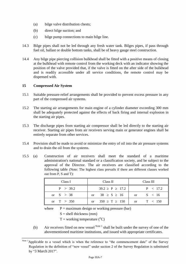
Page IIIA-7
(a) bilge valve distribution chests;
(b) direct bilge suction; and
(c) bilge pump connections to main bilge line.
14.3 Bilge pipes shall not be led through any fresh water tank. Bilges pipes, if pass through
fuel oil, ballast or double bottom tanks, shall be of heavy gauge steel construction.
14.4 Any bilge pipe piercing collision bulkhead shall be fitted with a positive means of closing
at the bulkhead with remote control from the working deck with an indicator showing the
position of the valve provided that, if the valve is fitted on the after side of the bulkhead
and is readily accessible under all service conditions, the remote control may be
dispensed with.
15 Compressed Air System
15.1 Suitable pressure-relief arrangements shall be provided to prevent excess pressure in any
part of the compressed air systems.
15.2 The starting air arrangements for main engine of a cylinder diameter exceeding 300 mm
shall be adequately protected against the effects of back firing and internal explosion in
the starting air pipes.
15.3 The discharge pipes from starting air compressor shall be led directly to the starting air
receiver. Starting air pipes from air receivers serving main or generator engines shall be
entirely separate from other services.
15.4 Provision shall be made to avoid or minimize the entry of oil into the air pressure systems
and to drain the oil from the systems.
15.5 (a) Construction of air receivers shall meet the standard of a maritime
administration's national standard or a classification society, and be subject to the
approval of the Director. The air receivers are classified according to the
following table (Note: The highest class prevails if there are different classes worked
out from P, S and T):
Class I Class II Class III
P > 39.2 39.2 P 17.2 P < 17.2
or S > 38 or 38 S 16 or S < 16
or T > 350 or 350 T 150 or T < 150
where P = maximum design or working pressure (bar)
S = shell thickness (mm)
T = working temperature (oC)
(b) Air receivers fitted on new vessel Note 1
shall be built under the survey of one of the
abovementioned maritime institutions, and issued with appropriate certificates.
Note 1Applicable to a vessel which is when the reference to “the commencement date” of the Survey
Regulation in the definition of “new vessel” under section 2 of the Survey Regulation is substituted
by “3 March 2017”.
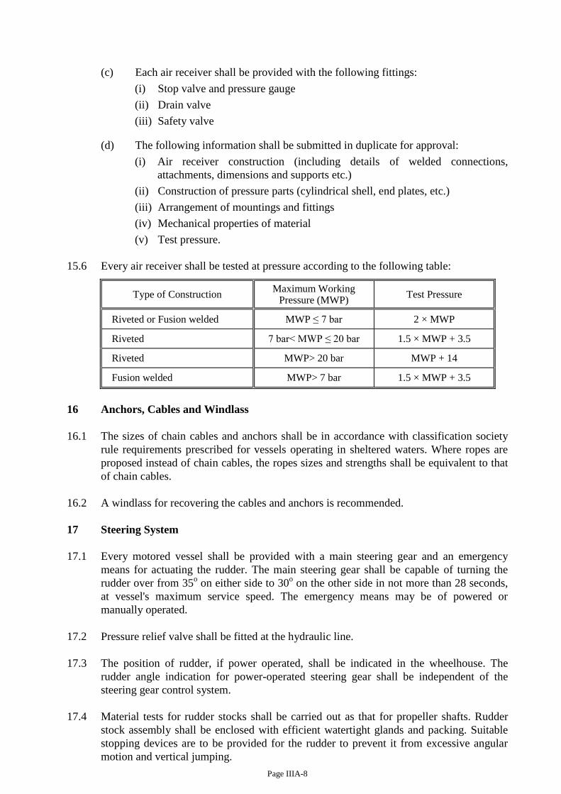
Page IIIA-8
(c) Each air receiver shall be provided with the following fittings:
(i) Stop valve and pressure gauge
(ii) Drain valve
(iii) Safety valve (d) The following information shall be submitted in duplicate for approval:
(i) Air receiver construction (including details of welded connections,
attachments, dimensions and supports etc.)
(ii) Construction of pressure parts (cylindrical shell, end plates, etc.)
(iii) Arrangement of mountings and fittings
(iv) Mechanical properties of material
(v) Test pressure.
15.6 Every air receiver shall be tested at pressure according to the following table:
Type of Construction Maximum Working
Pressure (MWP) Test Pressure
Riveted or Fusion welded MWP ≤ 7 bar 2 × MWP
Riveted 7 bar< MWP ≤ 20 bar 1.5 × MWP + 3.5
Riveted MWP> 20 bar MWP + 14
Fusion welded MWP> 7 bar 1.5 × MWP + 3.5
16 Anchors, Cables and Windlass
16.1 The sizes of chain cables and anchors shall be in accordance with classification society
rule requirements prescribed for vessels operating in sheltered waters. Where ropes are
proposed instead of chain cables, the ropes sizes and strengths shall be equivalent to that
of chain cables.
16.2 A windlass for recovering the cables and anchors is recommended.
17 Steering System
17.1 Every motored vessel shall be provided with a main steering gear and an emergency
means for actuating the rudder. The main steering gear shall be capable of turning the
rudder over from 35o on either side to 30
o on the other side in not more than 28 seconds,
at vessel's maximum service speed. The emergency means may be of powered or
manually operated.
17.2 Pressure relief valve shall be fitted at the hydraulic line.
17.3 The position of rudder, if power operated, shall be indicated in the wheelhouse. The
rudder angle indication for power-operated steering gear shall be independent of the
steering gear control system.
17.4 Material tests for rudder stocks shall be carried out as that for propeller shafts. Rudder
stock assembly shall be enclosed with efficient watertight glands and packing. Suitable
stopping devices are to be provided for the rudder to prevent it from excessive angular
motion and vertical jumping.
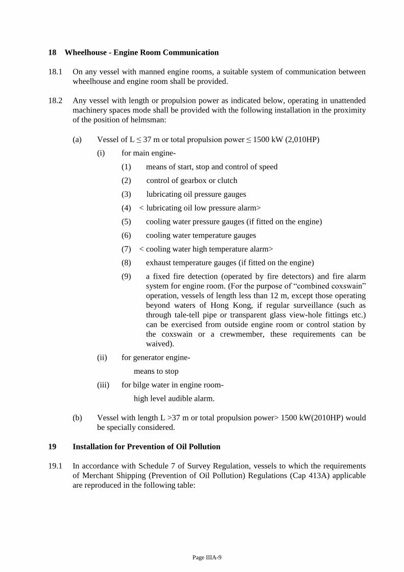
Page IIIA-9
18 Wheelhouse - Engine Room Communication
18.1 On any vessel with manned engine rooms, a suitable system of communication between
wheelhouse and engine room shall be provided.
18.2 Any vessel with length or propulsion power as indicated below, operating in unattended
machinery spaces mode shall be provided with the following installation in the proximity
of the position of helmsman:
(a) Vessel of L ≤ 37 m or total propulsion power ≤ 1500 kW (2,010HP)
(i) for main engine-
(1) means of start, stop and control of speed
(2) control of gearbox or clutch
(3) lubricating oil pressure gauges
(4) < lubricating oil low pressure alarm>
(5) cooling water pressure gauges (if fitted on the engine)
(6) cooling water temperature gauges
(7) < cooling water high temperature alarm>
(8) exhaust temperature gauges (if fitted on the engine)
(9) a fixed fire detection (operated by fire detectors) and fire alarm
system for engine room. (For the purpose of “combined coxswain”
operation, vessels of length less than 12 m, except those operating
beyond waters of Hong Kong, if regular surveillance (such as
through tale-tell pipe or transparent glass view-hole fittings etc.)
can be exercised from outside engine room or control station by
the coxswain or a crewmember, these requirements can be
waived).
(ii) for generator engine-
means to stop
(iii) for bilge water in engine room-
high level audible alarm.
(b) Vessel with length L >37 m or total propulsion power> 1500 kW(2010HP) would
be specially considered.
19 Installation for Prevention of Oil Pollution
19.1 In accordance with Schedule 7 of Survey Regulation, vessels to which the requirements
of Merchant Shipping (Prevention of Oil Pollution) Regulations (Cap 413A) applicable
are reproduced in the following table:
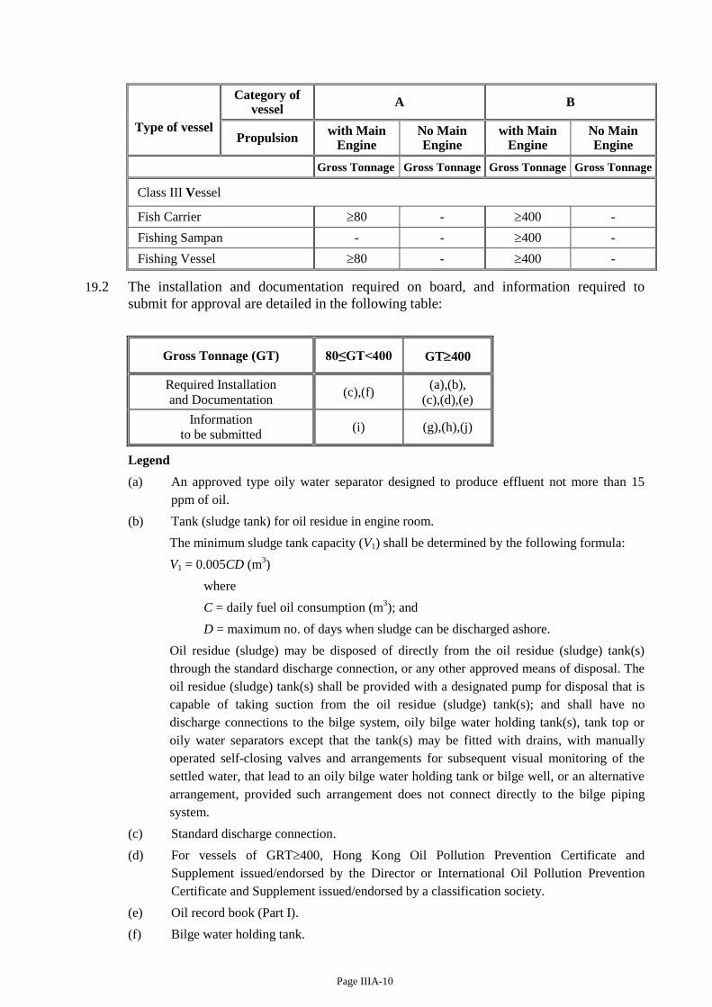
Page IIIA-10
Type of vessel
Category of vessel
A B
Propulsion with Main
Engine No Main Engine
with Main Engine
No Main Engine
Gross Tonnage Gross Tonnage Gross Tonnage Gross Tonnage
Class III Vessel
Fish Carrier 80 - 400 -
Fishing Sampan - - 400 -
Fishing Vessel 80 - 400 -
19.2 The installation and documentation required on board, and information required to
submit for approval are detailed in the following table:
Gross Tonnage (GT) 80≤GT<400 GT400
Required Installation
and Documentation (c),(f)
(a),(b),
(c),(d),(e)
Information
to be submitted (i) (g),(h),(j)
Legend
(a) An approved type oily water separator designed to produce effluent not more than 15
ppm of oil.
(b) Tank (sludge tank) for oil residue in engine room.
The minimum sludge tank capacity (V1) shall be determined by the following formula:
V1 = 0.005CD (m3)
where
C = daily fuel oil consumption (m3); and
D = maximum no. of days when sludge can be discharged ashore.
Oil residue (sludge) may be disposed of directly from the oil residue (sludge) tank(s)
through the standard discharge connection, or any other approved means of disposal. The
oil residue (sludge) tank(s) shall be provided with a designated pump for disposal that is
capable of taking suction from the oil residue (sludge) tank(s); and shall have no
discharge connections to the bilge system, oily bilge water holding tank(s), tank top or
oily water separators except that the tank(s) may be fitted with drains, with manually
operated self-closing valves and arrangements for subsequent visual monitoring of the
settled water, that lead to an oily bilge water holding tank or bilge well, or an alternative
arrangement, provided such arrangement does not connect directly to the bilge piping
system.
(c) Standard discharge connection.
(d) For vessels of GRT400, Hong Kong Oil Pollution Prevention Certificate and
Supplement issued/endorsed by the Director or International Oil Pollution Prevention
Certificate and Supplement issued/endorsed by a classification society.
(e) Oil record book (Part I).
(f) Bilge water holding tank.
Page IIIA-11
The minimum capacity (V) of the tank is to be determined by the following formula:
V = 0.9 P + 50 litres
where P = total horsepower of main engine(s), in kW.
The above formula is for an interval of discharge of 18 hours. For alternate intervals of
discharge, the capacity shall be adjusted accordingly.
(g) Installation plans for oily-water separator consist of:
(i) piping arrangements, and
(ii) wiring diagram of electrical installation.
(h) Sludge tank and discharge arrangement plans include:
(i) construction, size and location of sludge tank; and
(ii) piping diagram of sludge tank from machinery spaces to reception facility via
standard discharge connection.
(i) Bilge water holding tank and discharge arrangement plans include:
(i) construction, size and location of bilge holding tank; and
(ii) piping diagram of bilge water holding tank from machinery spaces to reception
facility via standard discharge connection.
(j) Shipboard oil pollution emergency plan (not required for sludge oil carriers).
19.3 Vessels shall maintain a valid certificate relevant to prevention of oil pollution as
required by Merchant Shipping (Prevention of Oil Pollution) Regulations (Cap 413 sub.
leg A) for the intended purpose of the vessel.
19.4 Provisions for discharge prohibition for oil pollution prevention as stipulated in Cap 313,
Cap 413 and Cap 548 must be complied with for all vessels, including those vessels not
mandatory required to provide with the physical arrangements/ equipment/document on
board as indicated in sections 19.1 and 19.2.
PART 4 ELECTRICAL INSTALLATION
20 Electrical Power Source
20.1 Nominal voltage of electrical system is recommended to be 380V for generation and
power circuits, 220V for lighting and distribution circuits and 24V D.C. for low voltage
circuits.
20.2 The hull return system shall not be used for power or lighting.
20.3 Where electrical power constitutes the only means of driving the lubrication oil pump and
cooling water pump for the main engine, a main source of electrical power shall be
provided which shall include at least two generating sets, one of which shall be driven by
internal combustion engine.
20.4 The vessel’s emergency lighting, navigation lights for vessels of length exceeding 24
metres, fixed fire extinguishing system, fire detection and alarm system and public
address system shall be provided with emergency power supply of sufficient capacity.
20.5 For vessels built on or after 29 November 2014 the emergency source of power shall not
be located below the full-load waterline of the vessel.

Page IIIA-12
20.6 Ventilation fans serving machinery or cargo spaces, engines' oil fuel pumps and other
similar oil pumps shall be capable to be stopped outside of the space where the appliance
is situated.
20.7 Each navigation light shall be connected separately to the distribution board served for
this purpose.
<20.8 In every electric or electro-hydraulic power steering gear system on vessel:
(a) the steering gear shall have two independent sets of supply cables connecting
direct to main switchboard;
(b) the supply circuits of steering gear control system shall be provided with short
circuit protection only;
(c) the steering gear motors shall have an overload alarm instead of overload
protection. The short circuit protection shall be not less than twice the total rated
current of the motor in the circuit protected.
This subsection is not applicable to vessels fitted with a separate power-operated means
of steering.>
21 Precautions against Shock, Fire and Other Hazards of Electrical Origin
21.1 (a) Exposed permanently fixed metal parts of electrical machines or equipment which
are not intended to be "live", but which are liable under fault conditions to
become "live" shall be earthed unless they are supplied at a voltage not exceeding
50 volts.
(b) Electrical apparatus shall be so constructed and so installed that it shall not cause
injury to person when handled or touched in the normal manner.
21.2 Main and emergency switchboards shall be so arranged as to give easy access as may be
needed to apparatus and equipment, without danger to attendants. The sides and backs
and, where necessary, the fronts of switchboards, shall be suitably guarded. Exposed
"live" parts having voltages exceeding 50 volts shall not be installed on the front of such
switchboards. There shall be non-conducting mats or gratings at the front and rear, where
necessary.
21.3 The distribution system if exceeds 50V, whether primary or secondary, for power or
lighting, with no connection to earth is used, a device capable of monitoring the
insulation level to earth shall be provided.
21.4 (a) The voltage rating of any cable shall not be less than the nominal voltage.
(b) Every conductor of a cable, flexible cable or flexible cord shall be capable of
carrying the maximum current which will normally flow through it without
exceeding the appropriate current rating as specified by manufacturer of the cable.
(c) Cable runs shall be selected so as to avoid action from condensed moisture or drip.
Cables shall, as far as possible, be remote from sources of heat, such as hot pipes,
resistors, etc.
(d) Cables shall be prevented from mechanical damage. When necessary cables shall
be enclosed in suitable conduits or casings, or armoured cables shall be used.
21.5 (a) Circuits shall be protected against short circuit and overload.
Page IIIA-13
(b) The current rating of circuit breaker shall not exceed the current rating of the
smallest size of cable in the circuit protected by the circuit breaker.
21.6 Lighting fittings shall be arranged to prevent temperature rises which could damage the
wiring and to prevent surrounding material from becoming excessively hot.
21.7 In spaces where flammable gas mixtures are liable to collect and in any compartment
assigned principally to the containment of an accumulator battery, the electrical fittings
shall be of flameproof type.
21.8 (a) The housing of accumulator batteries shall be properly stowed in a locker which
shall be well ventilated.
(b) Accumulator batteries shall not be located in the crew spaces.
<21.9 A lightning conductor is recommended to be fitted for a vessel which hull or mast is
constructed of nonconductive materials. The lightning conductor might be connected to
a copper plate fixed to the vessel's hull well below the lightship waterline. >
21.10 When any work to be carried out on electrical appliances a signboard showing “Work in
Progress” shall be displayed at prominent position of the electrical panel to prohibit
anyone from operating the panel.
PART 5 REFRIGERATION INSTALLATION
22 Refrigerating Chamber and Refrigerating Machinery
22.1 Refrigerating Chamber
22.1.1 The insulation layer shall be intact and properly fixed.
22.1.2 Effective drainage arrangement shall be provided for the refrigerating chamber and
evaporator.
22.1.3 All accessories of the system including the thermometer, pressure gauge shall be properly
maintained to indicate the correct parameters.
22.1.4 Door alarm or manual call point, if provided, shall be properly maintained and routine
testing is necessary to ensure their correct functioning.
22.1.5 The chamber shall be well lit and evaporator fan, if provided, shall be fitted with
protective guard.
22.2 Refrigerating Machinery
22.2.1 All the accessories including the thermometer, pressure gauge, relief valve, liquid
indicator shall be properly maintained.
23.2.2 The relief valves and bursting disc shall not be blanked and damaged. Blow test would be
required if the stamp seal has been damage.
22.2.3 The high pressure (discharge) and low pressure (suction) cut-out of the refrigerating
compressor shall be properly maintained. Periodic testing is necessary to ensure their
normal functioning.
22.2.4 Insulation resistance of the electrical supply of the system shall not be less than 1 mega
ohms.

Page IIIA-14
22.2.5 Safety protective device of switchgear shall be properly maintained and tested to ensure
their normal functioning.
22.2.6 Control and safety cut-out of the system shall be properly maintained and tested to ensure
their normal functioning.
PART 6 RADIO EQUIPMENT INSTALLATION
23 Radio equipment installation (if required to be installed) must comply with the requirements
of relevant legislation of Hong Kong. Vessel which holds a valid port clearance or is
exempted under section 69(1) of the Ordinance from complying with section 28(1) of the
Ordinance), when operating in such areas, shall also comply with the requirement of local
legislation in order to ensure the needs of rescue and emergency communication.

Page IIIB-1
CHAPTER III B HULL CONSTRUCTION, MACHINERY, ELECTRICAL INSTALLATIONS
AND FITTINGS - CATEGORY B VESSEL
PART 1 GENERAL REQUIREMENTS (1) Fishing sampan of other than wooden construction shall be designed and built to the
requirements of the relevant rules and regulations as listed at Annex A, having regard the size, construction material and operational services of the vessel. Such rules and regulations shall be complied with in its entirety. However in the case of any inconsistency between this Code and the requirements of the classification society rules, this Code shall be complied with. Wooden fishing vessels shall be of adequate structural strength appropriate for the sea and weather conditions likely to be encountered in the intended area of operation.
(2) GRP fishing sampan of length less than 15 metres shall be built in a shipyard having been
certified competent for the construction by Marine Department or RA in the mainland, with regard to its facilities, organization and capability. A copy of the certification, if issued by the mainland authority, shall be furnished to Marine Department for consideration/record.
(3) Suitable means or device shall be provided to machinery, equipment, lifting gear, fish
handling and fish processing equipment, etc. so as to reduce to a minimum any danger to persons on board. Special attention shall be paid to moving parts, hot surfaces and other potential dangers.
PART 2 HULL CONSTRUCTION
1 Hull and Bulkheads
1.1 Any motor vessel shall be fitted with:
< (a) a collision bulkhead (for vessels of other than wooden vessels and of length (L) exceeding 8 m); >
(b) engine room fore bulkhead; and
(c) engine room aft bulkhead, unless the machinery space is situated at aft end of the vessel.
1.2 For vessels of other than wooden construction, the bulkheads shall be of watertight construction. Bulkheads in vessels of wooden construction shall be as far as practicable of watertight construction. Openings fitted on bulkhead for the passing of pipes, cables, etc. shall be accordingly constructed.
1.3 < Access opening fitted in a watertight bulkhead shall be equipped with effective watertight closing appliance. No opening is to be fitted in collision bulkhead on vessels other than wooden construction. >
1.4 A fishing sampan shall be fitted with superstructure or erection to enable the proper display of navigation lights.
1.5 A fishing sampan:
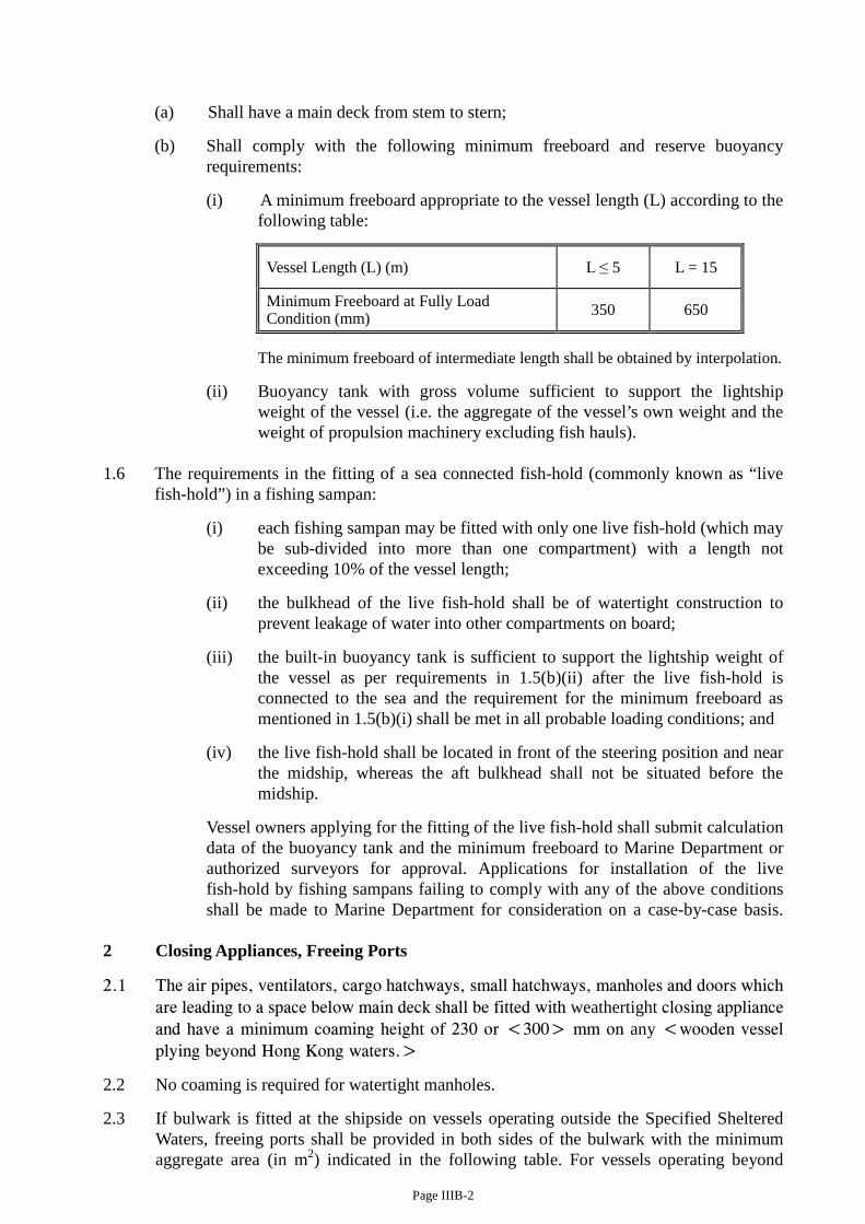
Page IIIB-2
(a) Shall have a main deck from stem to stern;
(b) Shall comply with the following minimum freeboard and reserve buoyancy requirements:
(i) A minimum freeboard appropriate to the vessel length (L) according to the following table:
Vessel Length (L) (m) L ≤ 5 L = 15
Minimum Freeboard at Fully Load Condition (mm) 350 650
The minimum freeboard of intermediate length shall be obtained by interpolation.
(ii) Buoyancy tank with gross volume sufficient to support the lightship weight of the vessel (i.e. the aggregate of the vessel’s own weight and the weight of propulsion machinery excluding fish hauls).
1.6 The requirements in the fitting of a sea connected fish-hold (commonly known as “live
fish-hold”) in a fishing sampan:
(i) each fishing sampan may be fitted with only one live fish-hold (which may be sub-divided into more than one compartment) with a length not exceeding 10% of the vessel length;
(ii) the bulkhead of the live fish-hold shall be of watertight construction to prevent leakage of water into other compartments on board;
(iii) the built-in buoyancy tank is sufficient to support the lightship weight of the vessel as per requirements in 1.5(b)(ii) after the live fish-hold is connected to the sea and the requirement for the minimum freeboard as mentioned in 1.5(b)(i) shall be met in all probable loading conditions; and
(iv) the live fish-hold shall be located in front of the steering position and near the midship, whereas the aft bulkhead shall not be situated before the midship.
Vessel owners applying for the fitting of the live fish-hold shall submit calculation data of the buoyancy tank and the minimum freeboard to Marine Department or authorized surveyors for approval. Applications for installation of the live fish-hold by fishing sampans failing to comply with any of the above conditions shall be made to Marine Department for consideration on a case-by-case basis.
2 Closing Appliances, Freeing Ports
2.1 The air pipes, ventilators, cargo hatchways, small hatchways, manholes and doors which are leading to a space below main deck shall be fitted with weathertight closing appliance and have a minimum coaming height of 230 or <300> mm on any <wooden vessel plying beyond Hong Kong waters.>
2.2 No coaming is required for watertight manholes.
2.3 If bulwark is fitted at the shipside on vessels operating outside the Specified Sheltered Waters, freeing ports shall be provided in both sides of the bulwark with the minimum aggregate area (in m2) indicated in the following table. For vessels operating beyond
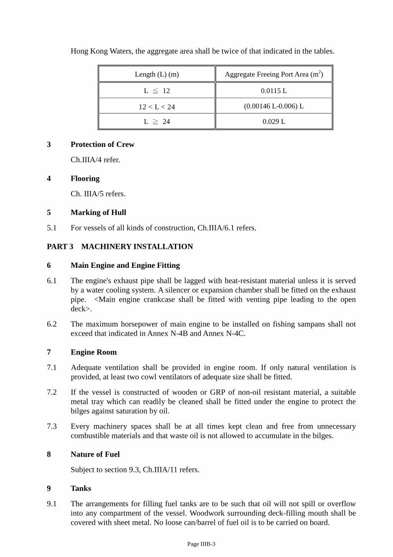
Page IIIB-3
Hong Kong Waters, the aggregate area shall be twice of that indicated in the tables.
Length (L) (m) Aggregate Freeing Port Area (m2)
L ≦ 12 0.0115 L
12 < L < 24 (0.00146 L-0.006) L
L ≧ 24 0.029 L
3 Protection of Crew
Ch.IIIA/4 refer. 4 Flooring
Ch. IIIA/5 refers. 5 Marking of Hull
5.1 For vessels of all kinds of construction, Ch.IIIA/6.1 refers. PART 3 MACHINERY INSTALLATION 6 Main Engine and Engine Fitting
6.1 The engine's exhaust pipe shall be lagged with heat-resistant material unless it is served by a water cooling system. A silencer or expansion chamber shall be fitted on the exhaust pipe. <Main engine crankcase shall be fitted with venting pipe leading to the open deck>.
6.2 The maximum horsepower of main engine to be installed on fishing sampans shall not exceed that indicated in Annex N-4B and Annex N-4C.
7 Engine Room
7.1 Adequate ventilation shall be provided in engine room. If only natural ventilation is provided, at least two cowl ventilators of adequate size shall be fitted.
7.2 If the vessel is constructed of wooden or GRP of non-oil resistant material, a suitable metal tray which can readily be cleaned shall be fitted under the engine to protect the bilges against saturation by oil.
7.3 Every machinery spaces shall be at all times kept clean and free from unnecessary combustible materials and that waste oil is not allowed to accumulate in the bilges.
8 Nature of Fuel
Subject to section 9.3, Ch.IIIA/11 refers. 9 Tanks
9.1 The arrangements for filling fuel tanks are to be such that oil will not spill or overflow into any compartment of the vessel. Woodwork surrounding deck-filling mouth shall be covered with sheet metal. No loose can/barrel of fuel oil is to be carried on board.
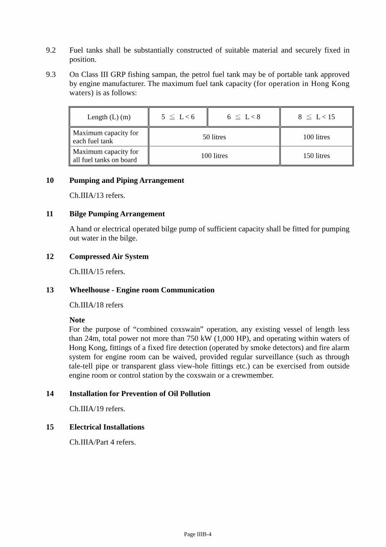
Page IIIB-4
9.2 Fuel tanks shall be substantially constructed of suitable material and securely fixed in position.
9.3 On Class III GRP fishing sampan, the petrol fuel tank may be of portable tank approved by engine manufacturer. The maximum fuel tank capacity (for operation in Hong Kong waters) is as follows:
Length (L) (m) 5 ≦ L < 6 6 ≦ L < 8 8 ≦ L < 15
Maximum capacity for each fuel tank 50 litres 100 litres
Maximum capacity for all fuel tanks on board 100 litres 150 litres
10 Pumping and Piping Arrangement
Ch.IIIA/13 refers. 11 Bilge Pumping Arrangement
A hand or electrical operated bilge pump of sufficient capacity shall be fitted for pumping out water in the bilge.
12 Compressed Air System
Ch.IIIA/15 refers. 13 Wheelhouse - Engine room Communication
Ch.IIIA/18 refers
Note For the purpose of “combined coxswain” operation, any existing vessel of length less than 24m, total power not more than 750 kW (1,000 HP), and operating within waters of Hong Kong, fittings of a fixed fire detection (operated by smoke detectors) and fire alarm system for engine room can be waived, provided regular surveillance (such as through tale-tell pipe or transparent glass view-hole fittings etc.) can be exercised from outside engine room or control station by the coxswain or a crewmember.
14 Installation for Prevention of Oil Pollution
Ch.IIIA/19 refers. 15 Electrical Installations
Ch.IIIA/Part 4 refers.
Related Documents