Ludhiana Smart City Project LUDHIANA SMART CITY LIMITED Design, Build, Testing & Commissioning of the following Packages along with Five Years of Operation and Maintenance including Two Years of Defect Liability in the ABD Area of Ludhiana under Smart City Mission: • Water Distribution Network & 24 x 7 domestic water supply • Sewerage Disposal System • Storm Water Drainage Network Specific Procurement Notice – Request for Bids (RFB) VOLUME II SECTION VII- WORK’S REQUIREMENTS

Welcome message from author
This document is posted to help you gain knowledge. Please leave a comment to let me know what you think about it! Share it to your friends and learn new things together.
Transcript

Ludhiana Smart City Project
LUDHIANA SMART CITY LIMITED
Design, Build, Testing & Commissioning of thefollowing Packages along with Five Years of Operationand Maintenance including Two Years of DefectLiability in the ABD Area of Ludhiana under SmartCity Mission:
• Water Distribution Network & 24 x 7 domestic water supply• Sewerage Disposal System• Storm Water Drainage Network
Specific Procurement Notice – Request for Bids (RFB)
VOLUME II
SECTION VII- WORK’S REQUIREMENTS

Ludhiana Smart City Project
WORK’S REQUIREMENTS

Ludhiana Smart City Project
Page i
Scope of Services
Table of Contents
7.1 DEFINITIONS .................................................................................................................. 17.2 PROJECT BACKGROUND .............................................................................................. 47.3 PROJECT OBJECTIVE .................................................................................................... 57.4 PROJECT LOCATION ..................................................................................................... 57.5 EXISING WATER SUPPLY SITUATION........................................................................... 67.6 EXISING SEWERAGE SITUATION .................................................................................. 67.7 EXISING STORM WATER DRAINAGE SITUATION ......................................................... 77.8 SCOPE OF WORK ........................................................................................................... 87.9 SUMMARY OF OBLIGATIONS UNDER THE CONTRACT ............................................. 157.10 PHASING OF CONTRACT ............................................................................................. 187.10.1 Mobilization Period ......................................................................................................... 187.10.2 Preparatory Period (Preparation of design during preparatory period) ............................. 197.10.2.1 Deliverable Documents for SIP ....................................................................................... 197.10.3 Operating and Management related Deliverable ............................................................. 207.10.4 SIP Schedule ................................................................................................................. 207.11 Methodology of Services ................................................................................................ 227.11.1 Distribution Network Improvement (DNI) on DMA basis .................................................. 227.11.2 Methodology for designing of DNI ................................................................................... 227.11.3 Methodology for measurement of NRW and real losses during operation services .......... 237.12 Methodology for commissioning of zone cum DMA ......................................................... 237.13 Methodology for Measurement of Performance Standards .............................................. 247.14 Methodology for Site Acquaintance ................................................................................ 247.15 Survey and Mapping ...................................................................................................... 257.16 SIP Implementation ........................................................................................................ 257.16.1 Construction of New Intake works and Raw water pump house ...................................... 257.16.2 Construction of New WTP .............................................................................................. 257.16.3 Construction of New Transmission Pipes ........................................................................ 257.16.4 Construction of new Water Distribution Pumping Stations ............................................... 267.16.5 Distribution Network works ............................................................................................. 267.16.6 Consumer Connections .................................................................................................. 267.16.7 Consumer Water Meters ................................................................................................ 267.16.8 District Meters for Metered Areas ................................................................................... 267.16.9 Sewerage system ........................................................................................................... 267.16.10 Storm water drainage system ......................................................................................... 277.16.11 Road restoration ............................................................................................................. 277.17 Illegal Connections: ........................................................................................................ 287.18 Consumer Relation Management Centre ........................................................................ 287.19 Management Information System ................................................................................... 287.20 Establishing Billing Systems ........................................................................................... 297.21 Operating Obligations ..................................................................................................... 297.21.1 From Final Take over date to expiry of Operation Period of 5 years ................................ 307.22 DESIGN REQUIRMENTS FOR WATER TREATMENT PLANT ...................................... 357.22.1 Water Treatment Plant Process Design Requirements.................................................... 35

Ludhiana Smart City Project
Page ii
7.22.2 Location ......................................................................................................................... 357.22.3 Recommended Design Norms ........................................................................................ 357.22.4 Design Considerations ................................................................................................... 377.22.5 Raw Water Quality ......................................................................................................... 377.22.6 Process Guarantees ....................................................................................................... 387.22.7 Treated Water Quality .................................................................................................... 387.22.8 Treatment Requirement .................................................................................................. 407.22.9 Hydraulic levels of Water Treatment Plant: ..................................................................... 407.22.10 Conceptual Treatment Scheme ...................................................................................... 417.23 Design for Clear Water Transmission Mains ................................................................... 417.23.1 Hydraulic Modeling for Transmission System Design ...................................................... 427.24 Hydraulic Modelling for distribution system ..................................................................... 437.25 Design Criteria for Storm water drainage system ............................................................ 447.25.1 Return Period ................................................................................................................. 447.25.2 Rainfall Intensity ............................................................................................................. 457.25.3 Design Velocity .............................................................................................................. 457.25.4 Inlet Spacing .................................................................................................................. 457.25.5 Design methodology ....................................................................................................... 457.26 Structural Design Requirements ..................................................................................... 477.26.1 Design Submissions ....................................................................................................... 477.26.2 Design Standards ........................................................................................................... 477.26.3 Design Life ..................................................................................................................... 477.26.4 Design Loads ................................................................................................................. 487.26.5 Dead Load ..................................................................................................................... 487.26.6 Live Load ....................................................................................................................... 487.26.7 Wind Load ...................................................................................................................... 487.26.8 Earthquake Load ............................................................................................................ 487.26.9 Dynamic Load ................................................................................................................ 487.27 Mechanical Design Requirements .................................................................................. 487.27.1 Horizontal Split Casing Centrifugal Pump ....................................................................... 487.28 Electrical Design Requirements ...................................................................................... 497.28.1 Major Electrical Components of the Contract .................................................................. 497.28.2 Raw Water Pumping Station, 10 MLD Water Treatment Plant and Clear Water Pumping
Station ................................................................................................................................ 497.28.3 Proposed Water Distribution Station at Leisure Valley and Rose Garden ........................ 507.29 Instrumentation, Automation and Control System Design Requirements ......................... 507.29.1 Design Requirements for Instrumentation, Control, Automation and SCADA Systems .... 507.29.2 General Design Requirements ........................................................................................ 517.30 PARTICULAR TECHNICAL REQUIREMENTS – WATER TREATMENT PLANT ............ 517.30.1 New Water Treatment Plant Process Technical Requirements : General Arrangement of the
Works: Site Development .................................................................................................... 517.30.2 Scope of work ................................................................................................................ 547.30.3 Orientation ..................................................................................................................... 557.30.4 General Arrangement of Plant ........................................................................................ 557.30.5 Inlet to Works ................................................................................................................. 567.30.6 Brief Description and Specifications for Treatment Plant Units ........................................ 56

Ludhiana Smart City Project
Page iii
7.30.7 Inlet Chamber ................................................................................................................ 567.30.8 Flow Measuring Device .................................................................................................. 567.30.9 Flash Mixer .................................................................................................................... 577.30.10 Agitator for Flash Mixer Tank .......................................................................................... 577.30.11 Distribution Chamber ...................................................................................................... 577.30.12 Chemical House ............................................................................................................. 577.30.13 Clariflocculator ............................................................................................................... 587.30.14 Specifications Flocculation cum Settling Tank Mechanism .............................................. 587.30.15 Sludge scrappers ........................................................................................................... 597.30.16 Filters & Filter House ...................................................................................................... 607.30.17 Underdrain System......................................................................................................... 617.30.18 Air Scour Blowers ........................................................................................................... 627.30.19 Specification for Twin Lobe Type Rotary Air blower ........................................................ 637.30.20 Filter Back wash Pumps ................................................................................................. 647.30.21 Sump Pumps ................................................................................................................. 657.30.22 Backwash Water Handling Power and Control ................................................................ 657.30.23 Filter Building Lifting and Handling Equipment ................................................................ 657.30.24 Filter Building Ventilation ................................................................................................ 657.30.25 Filtered Water Flow Monitoring ....................................................................................... 657.30.26 Chlorine Contact Tank .................................................................................................... 667.30.27 Chlorination System: Chlorinator Room and Chlorine Drum Store ................................... 667.30.27.1 Chlorinator Room ........................................................................................................... 667.30.27.2 Chlorinator Booster Pumps ............................................................................................. 677.30.27.3 Injectors ......................................................................................................................... 677.30.27.4 Chlorine Container room ................................................................................................ 677.30.27.5 Safety Equipment ........................................................................................................... 687.30.27.6 Chlorine Leak Detectors ................................................................................................. 697.30.27.7 Ventilation System.......................................................................................................... 707.30.27.8 Chlorine Residual Monitors ............................................................................................. 717.30.27.9 Chlorination Power and Control ...................................................................................... 717.30.27.10 Service Water System .................................................................................................... 717.30.28 WTP Wastewater Recovery & Recycle System............................................................... 727.30.28.1 Dewatering System Feed Pumps.................................................................................... 737.30.28.2 Polyelectrolyte Make up and Dosing Pumps ................................................................... 737.30.28.3 Mechanical Sludge Dewatering System .......................................................................... 737.30.28.4 Recovered water storage tank ........................................................................................ 747.30.28.5 Sludge Storage Shed ..................................................................................................... 747.30.28.6 Water and Sludge Sampling ........................................................................................... 747.30.29 Sludge Treatment and Disposal Power and Control ........................................................ 757.30.30 List of Equipments/Instruments for Automatic operation of Water Treatment Plant ......... 757.30.31 Intercom System ............................................................................................................ 757.30.32 Laboratory and sampling system .................................................................................... 767.30.32.1 LABORATORY EQUIPMENTS ....................................................................................... 777.30.33 Brief Description of Instrumentation ................................................................................ 787.30.34 Brief Description and specification for Interconnecting Piping .......................................... 797.31 PARTICULAR TECHNICAL REQUIREMENTS – CIVIL WORKS .................................... 79

Ludhiana Smart City Project
Page iv
7.31.1 Joints ............................................................................................................................. 797.31.2 Partly/Fully Underground Liquid Retaining Structures- Basis for Design .......................... 807.31.3 Foundations ................................................................................................................... 807.31.4 Requirements for Reinforced and Plain Concrete Works (Structures).............................. 817.31.5 Requirements for Building Works.................................................................................... 827.31.6 Concrete Reinforcement ................................................................................................. 857.31.7 Requirements at Water Treatment Plant ......................................................................... 857.31.8 Administration and Control Building ................................................................................ 857.31.9 Buildings and site development Works ........................................................................... 867.31.10 Clear Water Reservoir, Sump ......................................................................................... 897.31.11 Clear Water Pump Station .............................................................................................. 907.31.12 Requirements for Other Area Development Works at Treatment Plant Campus .............. 927.31.13 Preparatory Works ......................................................................................................... 937.31.14 Boundary Wall and Gates ............................................................................................... 937.31.15 Horticulture and Landscaping ......................................................................................... 937.31.16 Roads, Paths and Hard-standings .................................................................................. 937.31.17 Security Cabins .............................................................................................................. 947.31.18 Workshop ....................................................................................................................... 947.32 PARTICULAR TECHNICAL REQUIREMENTS – MECHANICAL WORKS ...................... 957.32.1 Horizontal Split Casing Centrifugal Pump ....................................................................... 957.32.1.1 General Features of Pumps ............................................................................................ 957.32.1.2 Specifications for Horizontal Split Casing Pumps ............................................................ 957.32.1.3 Features & Material of Construction ................................................................................ 967.32.1.4 Accessories Required To Be Supplied With Pump .......................................................... 967.32.2 VALVES ......................................................................................................................... 967.32.2.1 AIR VALVE .................................................................................................................... 967.32.2.2 Non-Return Valve/ Rubber Flap Check Valve ................................................................. 977.32.2.3 GATE VALVE/SLUICE VALVE ....................................................................................... 987.32.2.4 PLUNGER TYPE FLOW CONTROL VALVES ................................................................ 997.32.3 Electric Actuator ........................................................................................................... 1007.32.4 EXPANSION BELLOWS .............................................................................................. 1057.32.5 PRESSURE REDUCING VALVES ............................................................................... 1057.32.6 DISMANTILING JOINTS .............................................................................................. 1067.32.7 Electrically Operated Hoists .......................................................................................... 1067.32.8 Hand Operated Hoists and Trolleys .............................................................................. 1077.32.9 Manually Operated Travelling Crane............................................................................. 1077.32.10 Electrically Operated Overhead Travelling Crane .......................................................... 1087.33 PARTICULAR TECHNICAL REQUIREMENTS – ELECTRICAL WORKS ..................... 1117.33.1 General ........................................................................................................................ 1117.33.2 Transformer Size selection Criteria ............................................................................... 1127.33.3 Electrical System for Proposed Intake works, Raw water system and 10 MLD Water
Treatment Plant ................................................................................................................. 1127.33.4 Electrical System for Proposed Water Distribution Pump Stations ................................. 1137.34 PARTICULAR TECHNICAL REQUIREMENTS - INSTRUMENTATION, AUTOMATION AND
CONTROL SYSTEM WORKS ........................................................................................... 1137.34.1 GENERAL .................................................................................................................... 113

Ludhiana Smart City Project
Page v
7.34.2 THE SCOPE and Battery Limits ................................................................................... 1137.34.3 Design Requirements for Instrumentation, Control, Automation and SCADA Systems . 1197.34.4 Design criteria for Instrumentation, Control, Automation and SCADA Systems .............. 1197.34.4.1 Instrumentation System ................................................................................................ 1197.34.4.2 PLC System ................................................................................................................. 1207.34.4.3 RTU System ................................................................................................................. 1217.34.4.4 SCADA System ............................................................................................................ 1217.34.5 Functional Design Specification (FDS, Sequence of Operation) .................................... 1217.34.6 Reference Standards ................................................................................................... 1227.34.7 Specifications for online water quality monitoring systems ............................................ 1227.34.7.1 Multi-parameter Controller System Specifications: ........................................................ 1237.34.7.2 Sensor Specifications: .................................................................................................. 1247.35 PARTICULAR TECHNICAL REQUIREMENTS - PIPE LINE WORKS ........................... 1307.35.1 High Density Polyethylene Pipes (HDPE Pipes) Scope ................................................. 1307.35.2 Applicable Codes ......................................................................................................... 1307.35.3 Designation .................................................................................................................. 1307.35.4 Colour .......................................................................................................................... 1317.35.5 Materials ...................................................................................................................... 1317.35.6 Raw Material ................................................................................................................ 1317.35.7 Anti-oxidant .................................................................................................................. 1317.35.8 Reworked Material ....................................................................................................... 1327.35.9 Effect of nature of soil on pipe performance .................................................................. 1327.35.10 Maximum Ovality of Pipe .............................................................................................. 1327.35.11 Wall Thickness ............................................................................................................. 1327.35.12 Length of Straight Pipe ................................................................................................. 1327.35.13 Coiling .......................................................................................................................... 1327.35.14 Workmanship / Appearance ......................................................................................... 1327.35.15 Marking of Pipes .......................................................................................................... 1327.35.16 Handling, Transportation Storage and Lowering of pipes .............................................. 1337.35.17 Lowering, Laying of Pipes............................................................................................. 1347.35.18 Jointing of Pipes ........................................................................................................... 1357.35.19 Bedding, Backfilling and Compaction ............................................................................ 1357.35.19.1 Bedding........................................................................................................................ 1357.35.19.2 Back Filling................................................................................................................... 1357.35.19.3 Compaction .................................................................................................................. 1367.35.20 Fittings & Specials ........................................................................................................ 1367.35.21 Welding Procedure ....................................................................................................... 1367.35.22 Tests to Establish Portability of Work ............................................................................ 1367.35.23 Hydraulic Testing ......................................................................................................... 1377.35.24 Measurement ............................................................................................................... 1377.35.25 Rate ............................................................................................................................. 1377.35.26 JOINTING MATERIAL: Detachable Joints .................................................................... 1377.35.27 MECHANICAL JOINTS ................................................................................................ 1377.35.28 FLANGED JOINTS ....................................................................................................... 1387.35.29 MS PIPE - TO BE USED FOR ENCASING AT ROAD / RAILWAY CROSSING ONLY . 1387.35.30 TOLERANCE ............................................................................................................... 138
Ludhiana Smart City Project
Page vi
7.35.31 INSIDE / OUTSIDE COATINGS ................................................................................... 1387.35.32 STEEL FLANGES ........................................................................................................ 1397.35.33 Reinforced Cement Concrete Pipes .............................................................................. 1397.35.34 Design ......................................................................................................................... 1397.35.35 Manufacturing .............................................................................................................. 1397.35.35.1 General ........................................................................................................................ 1397.35.35.2 Materials ...................................................................................................................... 1407.35.35.3 Cement ........................................................................................................................ 1407.35.35.4 Aggregates................................................................................................................... 1407.35.35.5 Mixing and Curing Water .............................................................................................. 1407.35.35.6 Reinforcement .............................................................................................................. 1407.35.35.7 Concrete ...................................................................................................................... 1407.35.35.8 Curing .......................................................................................................................... 1407.35.35.9 Dimensions .................................................................................................................. 1407.35.36 Workmanship and Finish .............................................................................................. 1407.35.37 Testing ......................................................................................................................... 1417.35.38 Sampling and Inspection .............................................................................................. 1417.35.39 Marking ........................................................................................................................ 1427.35.40 Jointing ........................................................................................................................ 1427.35.40.1 General ........................................................................................................................ 1427.35.40.2 Spigot and Socket joint (Rigid) ...................................................................................... 1427.35.40.3 Collar Joint (Rigid) ........................................................................................................ 1427.35.40.4 Flush Joint (Internal) ..................................................................................................... 1427.35.40.5 Flush Joint (External) ................................................................................................... 1427.35.40.6 Spigot and Socket (Semi-flexible) ................................................................................. 1437.35.40.7 Collar Joint (Semi-Flexible) ........................................................................................... 1437.35.40.8 Spigot and Socket Joint (Flexible)................................................................................. 1437.35.41 Cleaning of Pipes ......................................................................................................... 1437.35.42 Testing at work site ...................................................................................................... 1437.35.43 UNPLASTICIZED POLY VINYL CHLORIDE (PVC-U) PIPES: ...................................... 1447.35.44 Applicable Codes ......................................................................................................... 1447.35.45 MARKING .................................................................................................................... 1457.35.46 Inspection and testing:.................................................................................................. 1457.35.47 Joints ........................................................................................................................... 1457.35.48 LAYING AND JOINTING OF SEWERS ........................................................................ 1457.35.49 Laying and jointing of sewers lines by Trenchless Technology ...................................... 1467.35.50 Bedding........................................................................................................................ 1467.36 PARTICULAR TECHNICAL REQUIREMENTS – SEWER REHABILITATION WORKS. 1487.36.1 TERMINOLOGY AND GENERAL DESCRIPTIONS....................................................... 1487.36.2 Information for the execution of works ............................................................................ 1507.36.3 Site investigation ........................................................................................................... 1507.36.4 Safe Entry and Working in Sewers ................................................................................ 1517.36.5 Ventilation .................................................................................................................... 1517.36.6 Sewer Rehabilitation Works-Procedure .......................................................................... 1517.36.6.1 Preparation Work ......................................................................................................... 1517.36.6.2 Preparation Prior to Sewer Rehabilitation ....................................................................... 152

Ludhiana Smart City Project
Page vii
7.36.7 Proposed Sequence of Rehabilitation Work .................................................................... 1527.36.8 Sewer Inspection .......................................................................................................... 1537.36.9 Flow Diversion.............................................................................................................. 1537.36.9.1 Bypass Pumping/Diversion of Flow ............................................................................... 1537.36.9.2 Contractor to have Adequate Pumping Facilities ............................................................ 1547.36.10 Cleaning of Sewer Prior to Inspection ............................................................................. 1547.36.11 Sewer- Cleaning Immediately Prior to Rehabilitation ....................................................... 1557.36.12 Mass Roots, Intruding Laterals, Concrete Grout and Other Obstructions ........................ 1567.36.13 Removal of Heavy Grease Deposit, Encrustations/Crystallised Deposits in Sewers ........ 1577.36.14 Repair works prior to Lining & Sewer Rehabilitation works ............................................ 1577.36.14.1 Cleaning & Surface Preparation ................................................................................... 1577.36.14.2 Surface Preparation for TYPE II Linings ........................................................................ 1577.36.14.3 Inspection of Pipeline ................................................................................................... 1587.36.14.4 Treatment of Exposed Reinforcement ........................................................................... 1587.36.14.5 Infiltration Control ......................................................................................................... 1587.36.15 Structural Lining ........................................................................................................... 1587.36.16 Types of Lining Systems ............................................................................................... 1587.36.17 Definition of Lining Types.............................................................................................. 1597.36.17.1 Lining Type .................................................................................................................. 1597.36.18 General Design Requirements ....................................................................................... 1597.36.19 Hydraulic Requirements ................................................................................................ 1607.36.19.1 Reduction in the Cross Sectional Area ........................................................................... 1607.36.19.2 Design Responsibility ................................................................................................... 1607.36.19.3 Design Life ................................................................................................................... 1617.36.20 Structural Design of Liners ........................................................................................... 1617.36.20.1 CIPP Liner.................................................................................................................... 1617.36.20.2 CIPP Lining Systems .................................................................................................... 1617.36.20.3 Reference Documents and Standards .......................................................................... 1617.36.20.4 Notation ....................................................................................................................... 1637.36.20.5 Materials ...................................................................................................................... 1647.36.20.6 Materials for CIPP Lining .............................................................................................. 1647.36.20.7 Material Properties for Design ...................................................................................... 1667.36.20.8 Design Loads ............................................................................................................... 1677.36.20.9 Installation Design Checks ............................................................................................ 1677.36.20.10 Design Calculations ...................................................................................................... 1677.36.20.11 Definitions for Pipe Condition ........................................................................................ 1677.36.20.12 Design for Circular Pipes .............................................................................................. 1677.36.20.13 Retention of Existing Integrity of Sewer ......................................................................... 1707.36.20.14 Method Involving Internal Loading ................................................................................ 1707.36.20.15 Working shafts (Starting and Ending Pits) ..................................................................... 1707.36.20.16 General ........................................................................................................................ 1717.36.20.17 Additional Requirement for Manufacture of CIPP Linings .............................................. 1717.36.20.18 Appearance and Surface Condition .............................................................................. 1717.36.20.19 Pre - Liner .................................................................................................................... 1727.36.20.20 Trial section.................................................................................................................. 1727.36.20.21 Standard of Finish ........................................................................................................ 172

Ludhiana Smart City Project
Page viii
7.36.20.22 Reinstatement of Connections ...................................................................................... 1727.36.20.23 Finish (Hydraulic Acceptability) ..................................................................................... 1737.36.20.24 Quality Control ............................................................................................................. 1737.36.20.25 Process Control Sheet.................................................................................................. 1737.37 PARTICULAR TECHNICAL REQUIREMENTS – WATER METERS ............................. 1737.37.1 AMR Domestic Water Meters ....................................................................................... 1737.37.2 Applicable Standards ................................................................................................... 1767.37.3 Technical Specifications: .............................................................................................. 1767.37.4 Material of Construction ................................................................................................ 1777.37.5 Requirement for Totalizer and Totalizer Shield ............................................................. 1777.37.6 Meter Reading.............................................................................................................. 1787.37.7 AMR System: ............................................................................................................... 1787.37.8 AMR Software: ............................................................................................................. 1787.37.9 Warranty ...................................................................................................................... 1797.37.10 Maintenance liability ..................................................................................................... 1797.37.11 Spare parts .................................................................................................................. 1797.37.12 Marking on the Meter Body: .......................................................................................... 1807.37.13 Specific Requirements.................................................................................................. 1807.37.14 Lab Testing .................................................................................................................. 1807.37.15 Field Testing ................................................................................................................ 1807.37.16 Hand Hold Unit (HHU) .................................................................................................. 1817.37.17 House Service connections: ......................................................................................... 1827.37.18 Making House Service Connections ............................................................................. 1837.38 PARTICULAR TECHNICAL REQUIREMENTS – SURVEY & INVESTIGATIONS ......... 1837.38.1 Consumer Survey......................................................................................................... 1837.38.2 Internal Inspection of Sanitary Sewer Mains By CCTV Camera Including All Videos And
Reports ............................................................................................................................. 1837.39 PARTICULAR TECHNICAL REQUIREMENTS – MISCELLANEOUS ........................... 1877.39.1 Contractor's Offices, Stores and Services ..................................................................... 1877.39.2 First Aid at Office and work site .................................................................................... 1877.39.3 Testing Facilities, Laboratory ........................................................................................ 1877.39.4 Site Safety.................................................................................................................... 1877.39.5 Protection of Overhead and Underground Services ...................................................... 1887.39.6 Signboards ................................................................................................................... 1887.39.7 Site Drainage ............................................................................................................... 1897.39.8 Detours and Traffic Control ........................................................................................... 1897.39.9 Provision of Temporary Services .................................................................................. 1907.39.10 Protection of Adjoining Property and Reinstatement upon Completion .......................... 1917.39.11 Coordination with Other Authorities .............................................................................. 1917.39.12 Submissions by the Contractor ..................................................................................... 1917.39.13 Construction Program and Progress of Works .............................................................. 1947.39.14 Updating, Monitoring and Reporting Progress ............................................................... 1947.39.15 Quality Control ............................................................................................................. 1957.39.16 Site Records ................................................................................................................ 1977.39.17 Separation of Water and Sewer lines ............................................................................ 1987.39.18 Water Tightness Tests for the Reservoirs: .................................................................... 198

Ludhiana Smart City Project
Page ix
7.39.19 Testing, Disinfecting and Rinsing of Water Pipelines ..................................................... 2007.39.19.1 General ........................................................................................................................ 2007.39.19.2 Hydraulic tests for pipeline............................................................................................ 2007.39.19.3 Failure to pass the test ................................................................................................. 2027.39.19.4 Cleaning Out After Testing ........................................................................................... 2027.39.19.5 Disinfection .................................................................................................................. 2027.39.19.6 Water for Testing and Cleaning .................................................................................... 2037.39.19.7 Testing and Commissioning ......................................................................................... 2037.39.19.8 The main indicators for the successful commissioning are: ........................................... 2037.39.20 Particular Specifications – Operation Service ................................................................ 2047.39.20.1 Standard Manuals governing in project construction and operations ............................. 2047.39.21 Standard Operating Procedures (SOP) ......................................................................... 204

Ludhiana Smart City Project
1 | P a g e
7.1 DEFINITIONS
The words, terms and expressions beginning with capital letters and defined under this Section 7.1including those in Section 8 - General Conditions of Contract and those in Section 9 – Particular Conditionsof Contract shall, unless the context otherwise requires, have the meanings as described thereto / herein:
a) “Consumer Relation Management Centres” means the special centres, planned and established bythe operator to provide commercial and public relations services to consumers;
b) “Consumer or Customer” means the registered user of the water supplied through the meter at theprivate tap;
c) “Contract Completion” means the date as mentioned in the Contract Completion Certificate issued bythe Employer’s Representative to the contractor on fulfilment of his obligations in respect of both theDesign-Build and the Operation Service;
d) “Contract Date” means the date on which the contract is signed;
e) “Contractor” means the agency to design build the works;
f) “Contractor's Personnel” means personnel hired and deployed by the Contractor under provision ofWorks and Services ;
g) “CPHEEO” means the Central Public Health and Environmental Engineering Organization under theMinistry of Urban Development, Government of India;
h) “Critical Measurement Points” means the locations agreed for undertaking measurement forfacilitating the monitoring of minimum Service levels stipulated in Clause of Performance Standards;
i) “Design Build Period” means the period commencing from contract commencement date to the issueof Commissioning Certificate;
j) “Development Period” has the same meaning as Design Build Period;
k) “Electricity Department” means the local service provider supplying electricity for facilitating Operationof the facilities;
l) OHSR means Over Head Service Reservoir;
m) “Existing Assets” means infrastructure components, plant, machinery, equipment and any other unitsexisting at the site as on the Commencement Date in the ownership of the Owner of Assets;
n) “Government Agencies” means all those agencies comprising of local, state and central governmentauthorities directly or indirectly connected to provision of water and waste water collection services tothe consumers in Ludhiana;
o) “Mandatory Works” are listed in the Bill of Quantities and are required to be constructed, installed orerected and commissioned and/or rehabilitated in line with the provisions of this Contract;
p) ‘’MCL” means the Municipal Corporation, Ludhiana
q) “Minimum Service Levels" means the levels of service to be maintained in the operations,maintenance and management and service delivery to consumers, described in Clause ofPerformance Standards as per Section 9 of the Bid Document;

Ludhiana Smart City Project
2 | P a g e
r) “Minor Maintenance” means routine preventive or corrective maintenance works such as minorrepair, reconditioning, or replacement of spare parts to ensure serviceability of existing and newinfrastructure assets procured and installed by the Contractor including, pipes, electrical equipment,flow meters, pressure monitoring equipment, and consumer meters, starter panel, electro-mechanicalequipment etc.;
s) “Mobilization Period” means the period commencing from the Contract Commencement Date andextends up to limit defined further in this document;
t) “New Assets” means infrastructure components, plant, machinery, equipment and any other unitsprocured, supplied, installed, erected and commissioned by the Contractor during the Implementationperiod other than those existing on the site as on the Commencement Date;
u) “NRW” means Non-Revenue Water;
v) “Operator” means the same as the “Contractor”.
w) “Operator’s Demand Points” means the points where water will be supplied to the Operator by theMCL;
x) “Operating Payments” means the eligible payments towards operation, maintenance, repairs andservice;
y) "Physical Losses" is part of the UFW and represents the volume of water leaking from the system;
z) “Planned Maintenance” means activities required to undertake preventive maintenance of any or allassets existing or proposed to be installed under the Contract and /or those taken over for operationsunder this contract;
aa) “PMC” means the Project Management Consultants as appointed by the Employer;
bb) “Potable / Drinking Water Specification” means the water quality requirements of potable water to besupplied to the Operator as stipulated in IS 10500, Guidelines for Physical and Chemical Parametersand Table 2.3 Bacteriological Quality of Drinking Water, in the Manual on Water Supply andTreatment, CPHEEO, Government of India, Ministry of Urban Development, New Delhi, edition May1999;
cc) “Preparatory Period” or “Service Improvement Plan Preparation Period” is the period commencingfrom the Contract Commencement Date up to the time as specified in this document during whichtime the Contractor will prepare the Service Improvement Plan (SIP);
dd) "Project" means provision of 24x7 Water Supply System, Rehabilitation of Sewerage and Stormwater drainage system for ABD area in Ludhiana City;
ee) “Project Information Memorandum” or “PIM” shall mean the report prepared by the Employer detailingthe Project as provided in Section under Supplementary Information;
ff) “Release Event” shall mean an event beyond the responsibility of the Contractor or an event of forcemajeure;
gg) “Scheduled Design Build Completion Date” or “SDBCD” shall mean the date by which theconstruction of all the Works as per the agreed Service Improvement Plan are to be completed andcertified by the Employer’s Representative;

Ludhiana Smart City Project
3 | P a g e
hh) “Schedules or Schedule” means the schedules forming part of this contract, or any one of them, asthe context requires;
ii) “Scope of Services” shall mean all those services to be provided by the Contractor in accordance tothe obligations, activities, responsibilities and tasks in implementing the contract;
jj) “Service Area” means the ABD area where Operator or its successors is responsible for conveyingwater to Consumers and maintain sewerage and storm water drainage infrastructure;
kk) “Services” means all those activities as defined in the Scope of Services;
ll) “SIP” mean Service Improvement Plan proposed by the Contractor and approved by Employer’sRepresentative;
mm) “Sub-Project means” either the Water Supply or Sewerage system or Storm water drainage systemcomponent of the Project;
nn) ‘’UGSR’’ means Underground Service Reservoir
oo) “Water Distribution Network” is the network of pipelines downstream of the water storage capacities;
pp) "UFW" means Unaccounted for Water and is part of the NRW. It means that quantity of water, whichdoes not reach the desired destination from its upstream point of original measurement. UFWcomprises:
Apparent losses such as illegal water connections and metering inaccuracies; and
Real losses which are leakages in the transmission networks and / or process losses.

Ludhiana Smart City Project
4 | P a g e
7.2 PROJECT BACKGROUND
Ludhiana is the largest city in the state of Punjab. The city is spread over an area of 159.37 sqkm. The cityis located in district Ludhiana, which is the most centrally located district amongst the 20 districts of PunjabState. It falls within the Malwa region of the State of Punjab. Geographically the city lies at 30 56' Northlongitude and 75 52' East of Latitude.
The city is well connected by Road and Rail Network with the rest of the country. It is located on Amritsar-Delhi G.T. Road (NH-1) and Amritsar-Ambala railway line which are considered the back bone of the state.The city is located at a distance of about 100 kms. North-West of Chandigarh, “The Capital of Punjab”.River Satluj flows at a distance of about 8 kms. to the North of the city.
The city is divided into 75 nos. of wards. The population of Ludhiana city was 16,18,159 as per 2011census.
Ludhiana is amongst top 20 cities selected under first round of smart city mission. The projects under thesmart city mission shall be executed through an SPV viz. Ludhiana Smart City Limited (LSCL). Theobjective of Smart Cities Mission is to promote cities that provide core infrastructure and give a decentquality of life to its citizens, a clean and sustainable environment and application of ‘Smart’ Solutions
In line with the mission objective, LSCL intends to take-up the works of infrastructural improvement withrespect to Water supply, Sewerage and Storm water drainage within ABD area, under Smart city mission.
As per the scope, the works under Water Supply Improvement will include:
Intake works and Water Treatment Plant
Transmission network from WTP to UGSRs i/c construction of UGSRs and Pump House
New distribution network based on District metering area (DMA) basis;
House service connections with AMR meters;
Provision of 24-hour water supply; and
Works under Sewerage Improvement will include
a) Cleaning, CCTV inspection and asset mapping of existing Sewerage system
b) Rehabilitation of the existing sewerage network by replacing the damaged / hydraulically insufficientsections & Trenchless rehabilitation by providing standalone Structural lining for old Brick/RCCsewers; and
Works under Storm water drainage Improvement will include
a) Cleaning, CCTV inspection and asset mapping of existing Storm water drainage system
b) Provision of new Storm water drainage system in uncovered areas and integrating the same withexisting system;
The objective of the project is to improve the economic development by providing the infrastructureand service in the water supply, sewerage and storm water drainage sector. The improvement ofquality of life and thereby effective contribution of beneficiary people in the economic activity isexpected. The project therefore focuses on service delivery along with the creation of quality assetsand service delivery monitoring systems.

Ludhiana Smart City Project
5 | P a g e
A WATER SUPPLY
a) Distribution network configuration on District metering area (DMA) basis for maintainingNRW within acceptable limits;
b) Provision of individual metered connections to citizens;
c) Provision of uninterrupted continuous water supply; and
d) Efficiency improvement in water supply.
B Sewerage
a) Efficiency improvement in Sewerage system ;
C Storm Water Drainage
a) Storm water drainage network covering entire ABD area
b) Efficiency improvement in Storm water drainage system ;
7.3 PROJECT OBJECTIVE
The objective of the project is to supply water at desired quality and quantity at consumers connections aswell as to effectively collect and convey the sewage and storm water to the respective outfall throughseparate networks.
Bidder has to include in his offer the entire Scope of Services needed for achieving the objectives and theintentions of the project. Broadly the project will have following components:
SIP Preparation (Survey, Investigation, Methodology for project execution, Project Works DesignSubmissions & Approval)
Design Build Period (Construction and commissioning of the project components, includingcontinual designs submissions & approval as per the project methodology approved during SIPpreparation)
Operating Period
7.4 PROJECT LOCATION
The project area (ABD area) in Ludhiana is spread over 790 acres and bounded by Sidhwan canal,Ferozpur Road and National college road. Figure below presents the location of ABD area within Ludhianacity

Ludhiana Smart City Project
6 | P a g e
Fig 1 – Project (ABD) Area
7.5 EXISING WATER SUPPLY SITUATION
Water supply to ABD area is managed by Municipal Corporation, Ludhiana. The water supply system inABD area is based on sub-surface water. Ground water is being extracted through Tube-wells scatteredover the ABD area. There are 25 nos of Tube-wells under possession of MCL, which are being used tosupply water within ABD area through direct pumping into the distribution system. The water supply systemin intermittent with 10 hours supply (4 hours in morning, 2 hours in noon and 4 hours in evening) in a day.The distribution system is about 30-35 years old and mainly comprises of AC and CI pipes. AC pipesreportedly contribute to more than 70% of existing water supply network in ABD area in Ludhiana.
The existing water supply system is in precarious state suffering from high NRW, inequitable distribution ofwater, intermittent supply, unmetered connections and quality issues. Further, the sustainability of presentsub-surface based water supply system is also an important factor especially in view of increased rate ofwater table depletion and associated environmental and ecological issues
In order to move to an ecologically sustainable and financially viable water supply system ensuringcontinuous potable water supply to consumers, there is an urgent need of complete refurbishment of theentire water supply system. Metering is one of the key factor to ensure that the envisage benefits arerealized to full extent.
7.6 EXISING SEWERAGE SITUATION
The sewerage system within project area primarily comprises of lateral and Trunk network of Stoneware,RCC and Brick sewers. Length of sewer network within project area is estimated to be around 55 kms. Age

Ludhiana Smart City Project
7 | P a g e
of sewer network is reportedly 25-35 years. The details regarding exact alignment, size, depth and conditionof existing sewers are not available.
There are no Sewage pump stations and Sewage Treatment Plant in project area. The sewage of ABD areais taken to Balloke STP through a Trunk Network of 72” – 78” – 90” – 96” sizes.
In absence of a separate storm water drainage system, the storm water is discharged through the seweragesystem resulting in overloading of sewers and eventually leading to overflow of sewage during rains.Besides this, certain sections of existing sewers are either frequently suffering from blockage reportedly dueto inadequate design slopes or have frequent sanitary sewer overflow due to insufficient hydraulic capacity.
Considering the fact that existing sewerage system is almost nearing its design life (generally 30 years),considerable investment might be required in near future to maintain the desired service levels. Therefore,there is an urgent need to prepare an Asset Management Framework for existing sewerage system. One ofthe requirements is to carryout de-silting and CCTV inspection of entire sewerage network within ABD areato gather the actual condition of sewers. Ascertaining the present condition analysed with estimated futureflows will help the utility (MCL) to proactively carryout the operation & maintenance and plan for futurecapital investments.
Details of existing sewer network in project area is presented in table below.
S No. Size in (mm) Material Length in Meters
1. 200 SW 44,412
2. 250 SW 1692
3. 300 RCC 1216
4. 400 RCC 1064
5. 600 RCC 2735
6. 700 RCC 1647
7. 1950 Brick (Non-Pressure) 2123
7.7 EXISING STORM WATER DRAINAGE SITUATION
The existing Storm water Drainage system in project area mainly comprises of network of Trunk drains andvery few branch/lateral network, covering few parts of the project area. Owing to topography, excess stormwater flows under gravity and discharges to Buddha nala (Outfall). There is no intermediate detention /storage or storm water pumping station in the project area.
Total length of existing trunk Storm water Drainage network is approx. 5.6 km with size ranging from 250mm to 2850 mm. The material of construction is stoneware, RCC and Brick. In general, most of the drainsupto 250 mm diameter are of stoneware. The Trunk drains above 700 mm are mostly constructed of cast in-situ Brick or combination of Brick and RCC. The drains are mostly circular in shape. The age of drainagesystem ranges from 30 - 35 years.
Since there is partial coverage of storm drainage system, the storm water finds its way through sewers. Inview of the limited carrying capacity of sewerage system, the excess storm water flows on roads resulting ininundation. Moreover, overflow of sewage mixed with water creates unhygienic conditions leading toinconvenience to public.
A well planned storm water drainage system covering the entire project area is required to overcome theissues of overflow and inundation during rains.

Ludhiana Smart City Project
8 | P a g e
Details of existing sewer network in project area is presented in table below
SNo. Size in (mm) Material (Tentative) Length in Meters
1. 400 SW 745
2. 900 RCC 99
3. 1600 Brick (Non-Pressure) 1294
4. 2550 Brick (Non-Pressure) 1350
5. 2850 Brick (Non-Pressure) 2100
7.8 SCOPE OF WORK
The Scope of contract for construction (Design Build) and Operating period is detailed out in sections below.
A) SCOPE OF CONTRACT FOR DESIGN BUILD PERIOD
The Scope of work for Water supply, Sewerage & Storm water drainage during Construction (Design Build)period is detailed out inTable-1 Table -2 & Table-3 respectively.
Table 1: Scope of work and services – Water Supply
S.N. Components Indicative Quantities
1 Preparation of System improvement Plan (SIP)within specified period and according to thecontract conditions. SIP Preparation &Implementation shall include but not limited to theAll Survey & investigations, water quality testingfor ground and canal water, consumer survey, GISMapping by linking with geospatial data base,freezing DMA boundaries, Hydraulic Modelling,Control philosophy complete
For project area of 790 Acres(approx.)
2 Design, Supply and Installation of SCADA systemrequired for effective management of the watersupply system based on the continuous data, itsanalysis and management.
Entire water supply including Intakeworks, Raw water pump station,WTP, CWR, & Clear water pumpstation and UGSRs & Pump stationsand Distribution system based onDMA requirements
Intake works & Raw Water Components
3 Design, Construction Testing & commissioning ofintake structure of the required size at the canaltapping point, raw water gravity main of requiressize from intake structure to Raw water sump, in
12 MLD capacity

Ludhiana Smart City Project
9 | P a g e
S.N. Components Indicative Quantities
conformity to the technical specifications andcondition of bidding documents
4 Design, Construction Testing & commissioning ofRCC raw water sump and pump house withsuitable foundation system, including allnecessary inlet/overflow/draining etc pipingarrangements with control valves, rungs,electrically operated control valves amenable toSCADA operation, all instrumentation includingbut not limited to flow meter, turbidity analyzer,water level indicator etc., and raw water pumpingmachinery of required numbers and configurationincluding all necessary mechanical, electrical &instrumentation and other installation works,providing all necessary suction/delivery pipingarrangements with control valves and specials,arrangement for priming of pumps with suitablestand-by provisions all complete
1 Job
Water Treatment Plant
5 Design, Construction, trial run and successfulcommissioning of Complete Water TreatmentPlant of output capacity of 10 MLD with suitabledesign in conformity of specifications provided inbidding documents and relevant BIS code ofpractices, having provision of coagulation &flocculation, sedimentation, Rapid gravity filtration,disinfection, clear water reservoir and pumphouse, recycling of filter backwash & clarifiersludge, dewatering and disposal of sludge,laboratory, Administration building, Chemicalhouse, chlorination system, Master control room,all interconnecting piping & by-pass arrangementincluding all necessary Mechanical, Electrical,Instrumentation and SCADA works suitable forautomated operation of plant alongwith all internal& external electrification works including controlpanels, DG, for all the plant units and ancillarybuildings
New Water Treatment Plant of 10MLD output capacity
New Clear Water Pump Station withMinimum 3 nos (2 Working + 1Standby) Clear Water Pumpsincluding water hammer/Surgeprotection devices
New Clear Water Reservoir withminimum 1670 m3 capacity
Providing Master Control Centre forWater Distribution Monitoring andControl including Office cum SCADARoom.
Provision of space for later extensionto 12 mld capacity for WTP alongwith layout of WTP and otherstructures
Water Transmission Pipes

Ludhiana Smart City Project
10 | P a g e
S.N. Components Indicative Quantities
6 Design, Supplying, laying, jointing, testing &commissioning of DI (K7) clear water transmissionmains of required size and length, from Clearwater pump station at WTP to proposedUnderground service reservoirs including allnecessary earthwork, valves & specials, flow &pressure measurement and controldevices/instruments, valve chamber, supportingstructures, anchor/thrust blocks, road restorationetc.
As per design requirement and scopeof work
4.1 Kms (250 mm to 400 mm)
Underground Service Reservoirs & WaterDistribution Pumping Stations
7 Design, Construction, Testing & commissioning ofRCC underground service reservoir sump andpump house with suitable foundation system,including all necessary inlet/overflow/draining etcpiping arrangements with control valves, waterhammer / surge protection devices, rungs, ventpipes, manhole chamber cover & frame,electrically operated control valves amenable toSCADA operation, all instrumentation includingbut not limited to flow meter, turbidity analyzer,residual chorine analyzer, pH analyzer, water levelindicator etc., and clear water pumping machineryof required numbers and configuration to ensure24x7 water supply, with variable frequency driveincluding all necessary mechanical, electrical &instrumentation and other installation works,providing all necessary suction/delivery pipingarrangements with control valves and specials,arrangement for priming of pumps with suitablestand-by provisions all complete
Location – one each at At Leisure Valley Park andRose Garden
Two Nos- One for each zone
Capacity and pump configuration asper design requirement and scope ofwork
Water Distribution System
8 Design, Supplying, laying, jointing, testing &commissioning of clear water Distribution mains ofrequired size and length, from Underground
As per design requirement and scopeof work.
HDPE (PE 100/PN6) and DI K7

Ludhiana Smart City Project
11 | P a g e
S.N. Components Indicative Quantities
service reservoirs to Consumers including allnecessary earthwork, valves & specials, flow &pressure measurement and controldevices/instruments, valve chamber, supportingstructures, anchor/thrust blocks, road restorationetc
distribution pipes with diameterranging from 110mm to 400mm - 85Kms
9 Refurbishment of Tube-wells by providing and/orreplacing/rehabilitating the civil, mechanical,electrical facilties at existing Tube-well locationsincluding all necessary piping, valves, valvechambers, instrumentation & automation allcomplete
7 Nos
10 Design, Supplying, laying, jointing, testing &commissioning of transmission mains (DI – K7) ofrequired size and length from Tube-wells torespective Underground service reservoirsincluding all necessary earthwork, valves &specials, flow & pressure measurement andcontrol devices/instruments, valve chamber,supporting structures, anchor/thrust blocks, roadrestoration etc
As per design requirement and scopeof work.
4.1 Kms (200 mm to 350 mm)
11 Electromagnetic bulk flow meters, ultrasonic digitallevel transmitter, level transmitter, level controller,online water quality sensors LED display, datalogger, GSM Modem with connectivity andsoftware for PC through SCADA.
As per design requirement and scopeof work
12 Metered House Service Connection, with Electrofusion saddle, Ferrule, HDPE fittings and MDPEpipe, ball valve, AMR type consumer meter, meterbox where required etc.
Approx. 5,000
13 Operation and maintenance of entire systemincluding water distribution service delivery withperformance guarantee, meter reading, billingsystem and customer services including customerservice centres.
5 Years of O&M including 2 years ofDLP after commissioning

Ludhiana Smart City Project
12 | P a g e
Table 2: Scope of work and services – Sewerage
S.N. Components Indicative Quantities
1 Preparation of System improvement Plan SIP withinspecified period and according to the contractconditions. SIP Preparation & Implementation shallinclude but not limited to the Topographical survey todetermine sewer alignment, levels, M/H positions,including tracing of buried manhole chambers alongalignment, measurement of exact length betweenmanhole chambers & invert level ; Temporary/permanent plugging and blocking of sewer line, branchconnections for diversion of flows and removal of allplugs etc; Provide everything else required for diversionof flow by pumping and/or bypassing and to maintainthe sewerage system functioning normal and managingthe flow without any surcharging, overflows etc. duringthe de-silting, cleaning of the sewer includingloosening, desilt and thoroughly cleaning and removingdebris and objects such as boulders, bricks etc.bacteriological slimes, roots, encrustations, grease,carbonated deposits, etc. from the sewer line includingdisposal of silt / debris/ malba / objects etc. includingsolidification of silt/ malba /debris for disposal to thedumping sites, CCTV/ Photographic survey includingpan and zoom inspection of laterals and defects andsubmission of reports, Hydraulic modelling complete
For project area of 790 Acres(approx.)
2 Design, Supplying, laying, jointing, testing &commissioning of uPVC (SN 8 class) and RCC (NP 3with PE lining) pipes of required size and length,including all necessary earthwork, manhole chamber &Inspection chambers, road restoration etc
2.7 Km
3 Design, manufacture, supply, deliver on site and installStandalone structural lining system includingpreparatory site work and construction of working shaftand reinstatement and making good of rehabilitatedsewer and lateral connections etc. and endgrouting/sealing of the migration gap between the linerand the sewer at manhole chambers includingrehabilitation of Manhole chambers / Chambersincluding sealing of leaks, installation of PVCencapsulated footsteps, plastering, grouting and epoxycoating to lower portion of the manhole chambers up to1m height above the benching and epoxy painting oncement plastered surface up to top of the manholechambers, haunch repairs of manhole chambers/chambers as specified and raising of manholechambers and installation of new SFRC frame & covers
3.2 Km

Ludhiana Smart City Project
13 | P a g e
S.N. Components Indicative Quantities
to required level; Post CCTV videosurvey/Photographic survey of the rehabilitated sewerand submit video/photographic reports of size 600 mm,700 mm and 1950 mm
4 Operating and Maintenance of Sewerage System 5 Years of O&M including 2years of DLP aftercommissioning
Table 3: Scope of work and services – Storm water drainage
S.N. Components Indicative Quantities
1 Preparation of System improvement Plan (SIP) withinspecified period and according to the contractconditions. SIP Preparation & Implementation shallinclude but not limited to the Topographical survey todetermine existing storm water drains alignment,levels, M/H positions, including tracing of buriedmanhole chambers along alignment, measurement ofexact length between manhole chambers & invertlevel; Hydraulic modelling all complete
For project area of 790 Acres(approx.)
2 Desilting & condition assessment of the existing stormwater drainage system by Temporary/ permanentplugging and blocking of storm line, branchconnections for diversion of flows and removal of allplugs etc; Provide everything else required fordiversion of flow by pumping and/or bypassing and tomaintain the storm water drainage system functioningnormal and managing the flow without anysurcharging, overflows etc. during the de-silting,cleaning of the storm water drain including loosening,desilt and thoroughly cleaning and removing debrisand objects such as boulders, bricks etc.bacteriological slimes, roots, encrustations, grease,carbonated deposits, etc. from the drains includingdisposal of silt / debris/ malba / objects etc. includingsolidification of silt/ malba /debris for disposal to thedumping sites, CCTV/ Photographic survey includingpan and zoom inspection of laterals and defects andsubmission of reports,
5.6 Km.
3 Design, Supplying, laying, jointing, testing &commissioning of RCC (NP 2) pipes of required sizeand length, including all necessary earthwork,manhole chamber & Inspection chambers, roadrestoration etc.
29.5 Km

Ludhiana Smart City Project
14 | P a g e
S.N. Components Indicative Quantities
4 Operation and maintenance of system. 5 Years of O&M including 2 yearsof DLP after commissioning
The Scope of Services shall include all technical, managerial, administrative, commercial, environmental,and social interventions as required in accordance with acceptable, prudent water, waste water & stormwater drainage utility construction and management practices, ensuring safe and sustainable drinking watersupply services and efficient sewage and storm water drainage collection & disposal facilities for theConsumers in the Service Area. The Scope of Services mentioned in Tables above is neither exhaustivenor complete and is indicative only and the contractor is required to undertake his own detailed investigationof the Project Facilities to determine the complete Scope of Services for achieving the Minimum ServiceLevels as stipulated in the bid document.
B) SCOPE OF OPERATION PHASE AND MAINTENANCE
The Operation Services are divided in 2 categories.
1) O&M of created assets during DB period.
2) O&M of existing Assets as indicated in this documents.
The Contractor will be required to operate and maintain the constructed and existing assets in such way tomeet the consumer demands and as agreed upon during the SIP stage.
Table 4: Scope of Works under Operation Phase
S No Operational Requirements
1 Establishment of Consumer Relation ManagementCentres (1 No.) and central control centre atproposed WTP location including furniture,manpower, computer software and hardware asper requirement.
1 No.
2 Operation and Maintenance of entire water supplysystem in service area including Water TreatmentPlant, Raw water and clear water transmissionsystem, water distribution service delivery withperformance guarantee, meter reading, billing andcustomer services from CWR’s to the UGSR’s andentire distribution system in an uninterruptedmanner.
3 Management & maintenance of the seweragenetwork for collection & conveyance of sewageincluding maintenance of entire system fromproperty chambers upto outfall to trunk sewersoutside service area

Ludhiana Smart City Project
15 | P a g e
S No Operational Requirements
4 Management & maintenance of the storm waterdrainage network for collection & conveyance ofstorm water including maintenance of entire systemfrom gully chamber upto outfall location
5 Contractor will provide continuous on-the-jobtraining that will start from the day the contractorgets mobilized, and other capacity buildingprograms by the contractor as important regularactivities so that there is a smooth takeover fromcontractor on contract completion fromcommissioning date
The Scope of Services shall include all technical, managerial, administrative, commercial, environmental,and social interventions as required in accordance with acceptable, prudent water, waste water & stormwater drainage utility construction and management practices, ensuring safe and sustainable drinking watersupply services and efficient sewage and storm water drainage collection & disposal facilities for theConsumers in the Service Area. The Scope of Services mentioned in Tables above is neither exhaustivenor complete and is indicative only and the contractor is required to undertake his own detailed investigationof the Project Facilities to determine the complete Scope of Services for achieving the Minimum ServiceLevels as stipulated in the bid document.
7.9 SUMMARY OF OBLIGATIONS UNDER THE CONTRACT
The summary of obligations related to Water supply, Sewerage and Storm water drainage works under theContract are mentioned in the Table 5, 6 and 7 respectively.
Table 5: Water supply
Sl.No.
DescriptionNew/Rehab.
Scope
Design Rehab Build Operate Maintain
1. New Intake works, Rawwater main and Raw waterpumping station
New Yes No Yes Yes Yes
2. New Water Treatment Plant New Yes No Yes Yes Yes
3. New Underground ServiceReservoirs and Pumpingstation at Leisure valley park& Rose Garden
New Yes No Yes Yes Yes
4. New Treated water New Yes No Yes Yes Yes

Ludhiana Smart City Project
16 | P a g e
Sl.No.
DescriptionNew/Rehab.
Scope
Design Rehab Build Operate Maintain
transmission pipeline withsizes ranging from 250 mmto 400 mm
5. Laying 85 km of new watersupply Distribution system
New Yes No Yes Yes Yes
6. Approx. 5000 new HouseService Connections withAMR meters for the newsupply system,
New Yes No Yes Yes Yes
7. New Service centres forO&M.
New Yes No Yes Yes Yes
Table 6: Sewerage
Sl.No.
DescriptionNew/Rehab.
Scope
Design Rehab Build Operate Maintain
1. Cleaning, CCTV inspectionof existing Storm waterdrainage network
Rehab Yes Yes Yes Yes Yes
2. Supply, Laying, Testing andCommissioning of SewerageCollection network of uPVCand RCC-NP3 (with PElining) pipes with Manholechambers, Ventilating Shaftsand other allied works etc.complete
New Yes No Yes Yes Yes
3. Trenchless Rehabilitation ofexisting 1950 mm Bricksewer by StandaloneStructural lining
Rehab Yes Yes Yes Yes Yes
4. Operating and Maintenanceof entire Sewerage Systemwithin service area
New Yes No Yes Yes Yes

Ludhiana Smart City Project
17 | P a g e
Table 7: Storm Water Drainage
Sl.No.
DescriptionNew/Rehab.
Scope
Design Rehab Build Operate Maintain
1. Supply, Laying, Testing andCommissioning of new Stormwater drainage network ofRCC-NP2 pipes with Manholechambers and other alliedworks etc. complete
New Yes No Yes Yes Yes
2. Cleaning, CCTV inspection ofexisting Storm water drainagenetwork
Rehab Yes Yes Yes Yes Yes
3. Operating and Maintenance ofentire Storm water drainageSystem within service areaincluding gully chamber andupto discharge location
New Yes No Yes Yes Yes
Important milestone and key time periods as per the terms of Contract are given in Table 8
Table 8: Milestone and Key Time Periods
S.
No.Sectional Milestone
Completion Timefrom stipulated dateof contract start(days)
Event ofstart
Activities
Design Build Period
1 Mobilisation 30 days Commencement Date
2 Preparatory period -Preparation and approval ofService Improvement Plan(SIP); Preparation of Plans &Design
90 days Commencement Date
3 SIP Implementation 640 days Commencement Date
Design, Construction,testing, commissioningand completion of allworks as per milestones

Ludhiana Smart City Project
18 | P a g e
S.
No.Sectional Milestone
Completion Timefrom stipulated dateof contract start(days)
Event ofstart
Activities
to deliver water,sewerage & Storm waterdrainage services
Operation Service delivery
4 Operation and Maintenanceof entire existing and newassets in service area as perscope of work
1825 days From dateof takeover
O&M of entire watersupply, sewerage andstorm water drainageassets
5 Handing over back toEmployer
30 days 30 daysbefore Endof O&Mperiod
Joint verification ofassets, Issuance of O&Mperiod completioncertificate and jointsigning of Handing Overdocument
Note: To the extent possible, water supply pipeline and distribution system, sewerage network & Stormwater drainage network on a particular road will be laid simultaneously.
7.10 PHASING OF CONTRACT
The Contract is divided into two stages (i. design & build ii. Operation and maintenance services) spreadover the contract period; from the stipulated date of Contract Commencement up to the ContractCompletion Date.
I. Mobilization, preparatory and construction period as per approved designs and
II. Operation, Maintenance, Manage, Repairs and Service Delivery Period during the contractperiod till contract completion date.
7.10.1 Mobilization Period
During the 30 days mobilization period the contractor is required to:
Establish a furnished project office in Ludhiana.
Employ/mobilize the staff required for starting the preparatory work
Mobilize the teams for Survey & Investigation
Procure GIS based maps, project management etc.
Collect and study existing utility networks and facilities
Baseline study for consumers water consumption pattern, DMAs

Ludhiana Smart City Project
19 | P a g e
Mobilize vehicles, office (furnished), equipment, communication equipment.
7.10.2 Preparatory Period (Preparation of design during preparatory period)
During the Preparatory Period, the Contractor is required to:
Familiarize himself with the project site condition after required consultation
Collect data and maps etc. and review designs of project components etc.
Confirm/ conduct topographic survey to ascertain the levels, road width, existing services etc.
Surveys for all underground utilities up to 3.0 m depth and marking on GIS based maps bylinking with geo referenced points.
Carryout desilting and CCTV inspection of entire existing sewerage and storm water drainagenetwork
Conduct Door to Door consumer survey and prepare data base of the existing properties withservice connection details
Prepare an asset inventory report for existing infrastructure within service area.
Prepare & submit detailed design and drawings of entire Water supply scheme including all thecomponents from Intake works upto distribution system including consumer meters includingCivil, structural, Electro-mechanical, Instrumentation, SCADA works
Prepare & submit system improvement plan alongwith detailed design of Sewerage and Stormwater drainage system including hydraulic modelling
7.10.2.1 Deliverable Documents for SIP
(i) Design should be prepared including sectional completion requirements;
(ii) Detailed design, drawings and cost estimates of works;
(iii) Work plan, Methodology and timelines for implementation should be in line with the Employer’srequirements;
(iv) Detailing of integrated Contract Management Information System by using latest software likePrimavera, Microsoft office architecture, data capture, management and reporting structures,protocols including all related hardware, software, installation; .
(v) Contractor Personnel Deployment Plan;
(vi) Construction Plant and equipment deployment plan;
(vii) Cash-flow for the entire contract with sectional completion break up;
(viii) Asset Replacement Schedule with justification;
(ix) Detailed methodology for continuous monitoring of the performance of the Contractor inachieving and maintaining the Performance Standards for release of the eligible OperatingPayments;
(x) Compliance matrix of contract and service requirement, O&M requirement and other requirementlike social, environmental, resettlement etc and;

Ludhiana Smart City Project
20 | P a g e
7.10.3 Operating and Management related Deliverable
(i) Annual Operating Plan (AOP) covering all operations, maintenance and managementrequirements in the Service Area;
(ii) Emergency Response Plan (ERP); this shall also separately include response plan for effectiveemergency rectifications against any major break downs occurring from the WTP up to theservice area of this contract;
(iii) Public Relations Plan;
(iv) Standard Operating Procedures (SOPs) for routine operations and emergency responses;
(v) Water Quality Monitoring Program;
(vi) Energy optimization program;
(vii) Transmission System extension/ expansion policy;
(viii) Detailing of an Integrated Management Information System (MIS) including its architecture, datacapture, management and reporting structures, protocols including all related hardware,software, installation, and operation and maintenance requirements; and
(ix) Periodic reporting plan including the formats for different performance reports;
(x) The computer hardware and software improvement plan for continued operation of the MIS,instrumentation and SCADA
7.10.4 SIP Schedule
Schedule of various activities of the design is shown in Table 9:
Table 9: SIP Schedule and Penalties
S N Activity Target period forcompletion from contractcommencement date
Amount of penaltyto be recovered incase of delayedoutput
1 2 3 4
1 Mobilisation on site 30 days
2 Topographical survey and groundprofiling of the service area, plotsurveys and any other surveys toensure accurate design.
45 days Rs. 25,000 per day
3 Geotechnical Investigations at plotswhere components of water systemswill be constructed and alongalignments where pipelines will belaid
45 days Rs. 25,000/- per day

Ludhiana Smart City Project
21 | P a g e
S N Activity Target period forcompletion from contractcommencement date
Amount of penaltyto be recovered incase of delayedoutput
1 2 3 4
4 Desilting and CCTV inspection andsubmission of reports alongwith forexisting sewerage and storm waterdrainage infrastructure
75 days Rs. 25,000/- per day
5 Development of complete GIS mapusing Arc GIS/ for the water supply,sewerage and storm water drainagesystem
90 days Rs. 50,000 per day
6 Complete system design anddrawings, preparation of abstract offinal quantities and cost estimatesfor the designs
90 days Rs. 75,000 per day
7 Preparing PERT chart, manpower,equipment, mobilisation plan, cashflow plan, detailed methodology ofcontinuous monitoring etc.
90 days -
8 Detailed O&M plan, StandardOperating Procedures and policiesplan, Performance measurementplan.
90 days Rs. 75,000 per day
9 Compilation and submission ofdesigns and drawings in complete
90 days Rs. 75,000 per day
The Contractor shall submit the outcome of each activity for review of Employer’s Representativeimmediately after completion of the activity. Employer’s Representative will review the outcomes on regularbasis and will submit their review comments within 21 days of receipt of the document.
Contractor will develop data bases for water supply hydraulic and water quality parameters and the dailyBulk Supply at each delivery point including hourly flows and total supply, raw water received by thecontractor and treated water produced at water treatment plant, quality of water produced, pump operations,electric parameters and unaccounted for water (UFW).
Contractor shall also submit the activity wise the Monthly Report for monitoring by the employer. Progressof all activities will be reviewed on weekly basis for design part. Reports will be on Monthly basis duringconstruction part and daily basis during operations part.

Ludhiana Smart City Project
22 | P a g e
In case of delays in meeting timelines of design activities, penalty as per the sums indicated in column 4 willbe imposed and recovered from due payments. If the delays that occurred in activity milestones are coveredby the Contractor within the stipulated or extended period for Compilation and submission of designs incomplete, which is not attributable to Contractor, penalty imposed on account of such delays will berefunded.
7.11 Methodology of Services
7.11.1 Distribution Network Improvement (DNI) on DMA basis
The Distribution Network Improvement (DNI) shall be based on DMA basis. The Contractor shall, set uphydraulically isolated District Metered Areas (DMAs) within the service area of each UGSR. Each DMAcomprising of about 1000 to 2000 consumer connections shall be considered as basic administrative unit forthe purpose of sectional commissioning and O & M purpose. The Contractor shall design water supplydistribution network on DMA basis to ensure equitable, continuous, pressurized water supply to theConsumers by using the hydraulic model and simulating both present (2018) and future (Year 2048)conditions, Each DMA preferably have one inflow point and be isolated by installing valves / end plugs.DMA at entry point will be provided with a bulk flow meter and water quality sensor, pressure transmitter.Each DMA will have at least two Critical Measurement Points (CMPs) for continuous logging of pressure,and the CMPs shall be such that they should be at the critical low pressure areas (highest and/or farthestpoints from the command reservoir). The performance parameters of the contractor including O& M periodshall be assessed on DMA basis. The O&M agencies (EMPLOYER) will also organize themselves in thesame manner over the contract period. DMA wise monthly reports will be generated to assess the DMAperformance. Monthly meter readings will be taken and will be linked to the NRW assessment system.Contractor also may suggest good management practices. Lessons learnt from other utilities/agencies willalso be incorporated for better management services
7.11.2 Methodology for designing of DNI
The existing distribution system will not be used in the proposed Distribution Network Improvement (DNI)plan, as the entire existing distribution network will be replaced with new one under this contract. Sinceentire distribution system shall be new; therefore no measurement of current NRW level is required. Scopeof contractor will involve both technical and consumer orientation with social approach. The consumers shallbe taken in confidence and be informed time to time for the status update. A disconnection of oldconnections and old pipelines is very critical. Contractor will disconnect old connections and pipelines oncommissioning of new pipelines. It will be verified by project consultant before making payment in DMA. Allthe connections shifted from old to new system and new connections given shall be recorded on GIS baseddatabase duly attaching each connection with meter serial number to respective property with social andcontact data of each consumer available in database. This database shall be of use to understand demandof water and also for servicing consumers. Contractor will proactively provide individual house connectionsto poor households including those in slums and informal settlements.
Works shall be planned and executed to provide continuous pressurised water supply in each DMA. TheZones/DMAs shall be equipped with the instrumentation for monitoring the performance of service deliveryin the area. The instrumentation capable of transferring the real time data to the SCADA system shallinclude the parameters of performance evaluation of the contractor during the operation, maintenance andservice delivery. It shall include the DMA inlet flow meter, DMA outlet flow meter if any (if the outlet of oneDMA forms the inlet for other), flow and pressure control valves, level transmitters at reservoirs, the

Ludhiana Smart City Project
23 | P a g e
pressure transducers at critical measurement points. The consumer meter reading data for a given month ofall the consumers within DMA shall be entered in the computer every month and shall be used inconjunction with the Zone/DMA inlet and outlet meter data for the month to work out the NRW of theZone/DMA/complete system. The pressure readings transmitted by the pressure transducers at criticalpoints in DMA shall not only be used for the performance monitoring and payment mechanism but also forcontinuously improving the model, using it for providing connections to the new consumers dulyunderstanding its effect on the system' interpreting the possible leakages in the DMA using the bulk flowmeter and consumer meter data and running the model to understand the implication of the pressurereadings.
The Contractor's approach and methodology towards this work shall be in line with the overall principlesand thinking of the Employer stated above. The SIP for DNI shall be compatible with these concepts.
7.11.3 Methodology for measurement of NRW and real losses during operation services
The contractor's methodology shall also spell out how the NRW and real losses will be measured within hisbattery limit which starts at the outlet of the WTP’s and ends at the consumers within service area.
The monitoring is to be started as soon as DMA is commissioned and the contractor will submit details inkey parameters (pressure, bulk supply, consumer readings zone/ DMA wise etc.). The complete watersupply system will be controlled and operated on SCADA. The bulk supply of water at each stage i.e. CWR,UGSR, Zone & DMA will be accessed through SCADA on specifically designed software. Bulk flow meterreadings should register every day at fixed time. It should be accomplished through SCADA reportgeneration. Domestic water meter reading at stipulated time in stipulated periodicity (the periodicity can bekept weekly or as felt fit by the Engineer). The format output for the monitoring should be evolving in suchmanner which shall clearly shows key parameters of water supply system specifically NRW evaluationcalculations. As per the assessment of NRW, other interventions required to control leakages/losses shouldalso be identified which will have to be taken up to accomplish desired performance parameters specifiedunder the contract.
On the sewerage front, the contractor shall prepare detailed asset inventory of existing sewerageinfrastructure through survey & investigations including CCTV survey to ascertain the alignment, size, depthand condition of sewers. Based on the data, hydraulic modelling shall be carried out to check availablecapacities of different sections vis-à-vis estimated flows for present (2018) and future (2033 & 2048)conditions. The contractor shall develop the SIP with overall goal to connect each and every property inservice area to the system and to transport the collected sewage and sullage within service area to theoutfall sewer/s. The contactor's SIP when functional shall continue to provide service as per theperformance standards mentioned for service to the consumers. The methodology shall be prepared andgot approved from the Employer before preparing detailed SIP.
The contractor shall also prepare detailed asset inventory of existing storm water drainage infrastructurethrough survey & investigations including CCTV survey to ascertain the alignment, size, depth and conditionof drains. The SIP shall be developed considering integration of the proposed new network of drains withexisting system.
7.12 Methodology for commissioning of zone cum DMA
The contractor shall give a complete methodology for commissioning of DMAs which shall includean exhaustive and sequential method with the formats designed to achieve and monitor: DMA5

Ludhiana Smart City Project
24 | P a g e
• The distribution system pipelines in a DMA/ zone hydraulically tested
• Readiness of database of all the properties and consumer registered / unregistered to be connectedto the new system on GIS based map of the DMA with clear indication of roads.
• Proposal to connect all the consumers to the new system and methodology for pressure and flowcontrol of each consumer vis-à-vis his registered demand.
• Public awareness programs planned to achieve people's participation in managing demand byusing the continuously available water to their absolute need only and not to waste, and tocommunicate importance of metered system and its benefit.
• The water to be taken in UGSRs shall be calculated based on the demand of the population withceiling of 150 lpcd in any case. In no case in order to sustain demand of one zone for continuouswater supply, other area shall suffer. A continuous consumer awareness to spread the demand indifferent hours of the day to bring it to the use pattern considered in design shall be tried. The initialteething troubles shall be overcome at the earliest but not later than 45 days of commissioning ofzone/DMA.
• The billing shall be on time without fail for which a detail program shall be prepared. The first bill ontime gives early signal for those who have increased demand just because water is availablecontinuously.
• A vigilant surveillance to see that no reverse flow occur, no high consumptions go unnoticed shallbe done for first some months. The pattern of water flowing out of UGSRs be critically observed forthe entire day at 10 minutes interval for initial months. Unusual night flows shall be checked bysurveillance visits in the night at the time when unusual high flow is seen on bulk outlet meter.
7.13 Methodology for Measurement of Performance Standards
The Contractor shall develop a robust methodology and framework for measurement and monitoring ofPerformance Standards stipulated under the contract and proposed as part of the SIP. The Employer withthe assistance of the Employer’s representative shall verify the same and upon agreement between theParties the agreed methodology shall form the basis for monitoring the performance of the Contractor andapply the Non Performance Adjustments on the eligible Operating Payments in case of failure to meet theperformance standards.
7.14 Methodology for Site Acquaintance
As part of this activity, contractor is required to:
i. Establish contact with all relevant stakeholders MCL, PWD, NHAI, Electricity Distribution Company,Telecommunication companies and the local traffic police and other government agencies includingconsultants.
ii. Become familiar with the water supply system in service area, and the applicable standards andguidelines for water supply design, and with existing assets and current on-going works in theService Area. The contractor shall also study the works being done by MCL and other departmentsbeing undertaken during the same period in the same area.
iii. Satisfy himself with the nature and scope of work and the prevailing Site conditions.

Ludhiana Smart City Project
25 | P a g e
iv. Be familiar with governing Laws and regulations in order to undertake studies and constructionactivities under the Contract such as:
a. Occupational health and safety including workers compensation;
b. Signage for construction works and;
c. The permissions and co-ordination required from the different agencies
7.15 Survey and Mapping
The contractor shall digitize and validate all the footprints, roads, water bodies, electricity poles, watersupply and other infrastructure components in the service area on a base map provided by the employer. Adetailed topographical survey of the area shall be carried out using Total Station equipment and the spotlevels and the contours at 0.5 m interval shall be drawn on the GIS based digitized map in Arc GIS.Contractor will survey all underground utilities upto 3.0 m depth and mark on GIS based maps by linkingwith geo referenced points.
7.16 SIP Implementation
The Scope of Services during the implementation Period shall essentially comprise of implementing theapproved SIP based on the hydraulic model prepared for water distribution based on DMA approach,sewage network and storm water drainage network. SIP will be implemented in accordance to internationalbest practice and industry standards and sufficient care shall be taken by the Contractor in minimizingsupply interruptions, traffic disruptions and ensuring good and timely communications with the Consumersin the Service Area. During work execution, contractor would be required to inform the residents, say, of aparticular street, well in advance about the type of work, inconvenience expected, timelines for variousworks, etc. Contractor has to have a strong Public Relations and Community Outreach team. Contractor willplan sequencing of activities to synchronize water pipeline works, sewer works & storm water drainage tominimize the road excavation and restoration in the streets which will have two or all three pipelines.
All the Works and interventions proposed as part of the SIP shall be in conformity with the Specifications setout in the Employer’s Requirements. Implementation of the water supply transmission and distributionnetwork, sewer collection networks and storm water drainage networks in a given street / road shall betaken up simultaneously so that the people living in the area are not affected multiple times.
7.16.1 Construction of New Intake works and Raw water pump house
The scope includes construction of intake works at Sidhwan canal, raw water sump and pump house. Theraw water shall be pumped to inlet chamber of WTP by DI (K9) rising main of required diameter and length.
7.16.2 Construction of New WTP
Scope includes the construction of a new WTP of 10 MLD capacity including all civil, mechanical andElectrical, Instrumentation & SCADA items.
7.16.3 Construction of New Transmission Pipes
The scope includes Supply laying, jointing, testing and commissioning, and operation of the newtransmission pipes.

Ludhiana Smart City Project
26 | P a g e
7.16.4 Construction of new Water Distribution Pumping Stations
The scope includes the construction of 2 nos new underground service reservoir including pump house withrequired configuration of pumps to ensure 24x7 water supply with minimum 17 m pressure at consumer end
7.16.5 Distribution Network works
The contractor will implement the distribution network works in accordance to the technical specificationsand prudent industry practices. The primary objective of the Distribution Network is to ensure rationalized,equitable, continuous and pressurized water services to the Consumers in the Service Area on a DMAbased approach.
7.16.6 Consumer Connections
The Contractor shall undertake installation of new consumer connections using Electrofusion weldedconnection, a compression joint to receive HDPE pipe from tapping saddle followed by a compressionelbow and then MDPE pipe till ball valve followed by installation of a Consumer meter, accessories andmeter box (as required) at the nearest point inside the Consumer property boundary.
7.16.7 Consumer Water Meters
The consumer meters shall be AMR domestic water meters, inferential type, multi jet, magneticallycoupled, having dry dial, Class 'B' conforming to IS-779 : 1994 with up to date amendments or ISO4064:2014 standard and shall have ISI/EEC/OIML/MID certification mark on each meter and shall be withprotection class of IP-68. Water meter shall have anti magnetic properties/Immunity, as specified ISO:4064-2014.
The water meters shall be equipped with RF/GPS/GPRS based wireless remote trans-receiversinbuilt/directly fitted on the meter & wireless for A.M.R. reading. Remote Data collector / Concentrator with2G/3G modem, aerial / panel antenna for outdoor installation, Repeaters (if required), with necessaryCabinet & Extra antenna wire shall be provided for Outdoor installation. Meter Reading Software for Hourlydata collection shall be provided. The cost includes all license fee for the software upto the contract period.
7.16.8 District Meters for Metered Areas
District meters shall be Electromagnetic Meters (EM) either powered by electricity with adequate protectionagainst power fluctuations or EM’s for remote areas with adequate battery power supply. All EM’s have tobe connected to the SCADA System.
In the District Metered Areas, the water meter shall be adequately maintained. Pressure shall either becontrolled by the topography or pressure reducing valves, if necessary.
7.16.9 Sewerage system
The Contractor shall rehabilitate the existing sewerage works in service area as detailed hereunder andincluded as per the Bill of Quantities (BOQ) for the purpose of pricing in the Price Bid.
i. Supply, laying, jointing, hydraulic testing and commissioning the sewer network along withmanhole chambers and all allied works; as per scope indicated in the bid documents;
ii. Construction of property chamber and making connections between manhole chamber andproperty chamber (scope excludes internal piping works within property boundary upto propertychamber).

Ludhiana Smart City Project
27 | P a g e
iii. Rehabilitation of damaged trunk sewers by trenchless structural lining method, whereverreplacement of existing sewer by open cut method is not feasible
7.16.10 Storm water drainage system
The Contractor shall augment and rehabilitate the existing storm water drainage system in service area asdetailed hereunder and included as per the Bill of Quantities (BOQ) for the purpose of pricing in the PriceBid.
Supply, laying, jointing, hydraulic testing and commissioning the storm water drainage network along withmanhole chambers and all allied works; as per scope indicated in the bid documents;
7.16.11 Road restoration
Road restoration is a critical activity which requires special attention of the contractor. Following guidelinesshould be followed:
a) The contractor shall have to restore the road up to WMM stage including refilling trench in layers,watering, rolling and compacting to within 10days after trenching is completed in a particularstreet/reach. The contractor shall ensure that uncovered WMM length in total does not exceed 5.0KMat any stage of work and will complete the bituminous work regularly.
b) Contractor shall erect informatory board at his own cost showing type of work, inconvenienceexpected & timeline for various construction activities going to take place in a particular street or aparticular reach of road as per direction of Engineer in charge. Contractor shall submit detour andtraffic control plan and get approval from Engineer and appropriate government authorities prior tocarryout the works. All necessary provisions shall be ensured as defined in clause 7.39.8 of biddocument.
c) Contractor shall deploy a community outreach team to make strong relation with public prior to startof work in a particular ward/ area.
d) The contractor shall have to do the sequencing of activities as per direction of engineer in charge tosynchronize water pipe line, sewer and storm water pipeline work to minimize the road excavationand restoration in the street which will have two or all three pipe lines.
e) The cutting of existing C.C. pavement shall be done by using mechanical cutter to ensure cutting inregular line and the laying of C.C pavement shall be done below 30 degree ambient temperature.
i. Provisions of road restoration – Bituminous Road
a. For laying on B/T Surface - for road width up to 7 m, restoration up to WMM stage in trench widthand bituminous work (top wearing surface) in full width of the Existing Road.
b. For road width more than 7 m, restoration up to WMM stage in trench width and bituminous work(top wearing surface) limited to 7 m (2 lanes) duly covering the trenches.
ii. Provisions of road restoration – Cement Concrete Road
a. For cement concrete roads, restoration of different layers including lean concrete and CC pavementshall be done in trench width only.
In Bituminous road restoration, Use of Paver is mandatory for carriage way width above 3.75 m of roadrestoration.

Ludhiana Smart City Project
28 | P a g e
Notwithstanding all which has been laid down on road restoration, Employer’s representative with reasonsrecorded and prior permission of Employer will be authorized to come up with the site specific solutionbased on prevailing ground situation.
7.17 Illegal Connections:
The Contractor based on the findings from the Consumer Survey and its GIS based analysis or anothermeans, shall identify the illegal or un-authorized connections and inform employer for regularization of theconnections. On approval and after payment of prescribed charges by the Consumer, the Contractor shallthen rehabilitate the connection with the specification mentioned above. Until approval of regularization byemployer, the Contractor shall prepare and send temporary bills at the prescribed tariffs for such illegalconnections. The Employer will take a decision on this within a month's time from bringing to the notice. Thecontractor shall be more particular in bringing to the notice this list well in advance of commissioning newlines, as the old lines are to be made defunct.
7.18 Consumer Relation Management Centre
The Contractor shall design, develop and set up consumer relation management centre (CRMC) 1 no. ofarea not less than 40 m2 and one Central Control Centre (CCC) of about 60 sqm to facilitate receiving andresolving consumer requests in the areas of new connections, service deficiencies, resolution of billingdisputes, payment of bills etc. The consumers shall file their complaints through e-mail, text message frommobile phones, telephone, Fax and other electronic media. Contractor will maintain two toll free numberseach for water supply and sewerage/storm water drainage services at CCC. The Centres shall functionbetween 8am to 8pm during all working days and between 8am to 1pm during public holidays includingSundays. The CRMC and CCC shall be air conditioned and have reasonable space and furniture for theConsumers to wait, interact and represent their requirements. During the other off peak times of 8pm to8am, the Contractor shall have a facility to receive Consumer complaints through telephone, fax, textmessage, email and any other electronic means. The complaints once received should be acknowledgedautomatically and a registration number shall be given to the complainant immediately. The CRMC andCCC shall be equipped with sufficient human resources, hardware and software to facilitate continuousrecord of consumer requests, monitoring the resolution, and reporting completion of necessary actions andtasks.
7.19 Management Information System
Contractor shall develop, establish, operate and manage during the entire contract period a comprehensiveIntegrated Management Information System (MIS) in respect of all matters including but not limited to:
i. Design Built activities
ii. All the Operation and maintenance activities
iii. billings systems;
iv. Consumer services, including data bases relating to complaints and questions, response times andresolution;
v. Financial management, including accounting systems;
vi. Performance information systems; and
vii. Others as identified during SIP preparation and implementation.

Ludhiana Smart City Project
29 | P a g e
7.20 Establishing Billing Systems
The Contractor shall:
i. Prepare and monitor the profile of water service Consumers in the Service Area describing consumercategories and other attributes collected through consumer survey in a GIS platform geocoded to theproperty footprints. The database and software shall be in a position to analyse the number ofConsumers under each category, estimated average volume of water consumed per month, andestimated average revenue per month;
ii. Develop and implement basic Standard Operating Procedures for (i)service connections, (ii) preparingand issuing a bill for water service, (iii) how water consumption is estimated for Consumers meterunder repair;
iii. Develop and implement: (i) meter reading procedures and arrangements, (ii) meter reader control, and(iii) efficient and accurate meter reading practices.
7.21 Operating Obligations
From the design, built completion date (which shall also mean sectional completion date, the Contractorshall supply potable water to the legal and authorized Consumers and operate and maintain sewerage &storm water drainage services through the laid and commissioned sewerage & storm water drainagesystem. Contractor shall be responsible for operation, maintenance and management of water supplysewerage and storm water drainage services in service area as detailed below:
No Obligation Period
1 Operating Intake works, Raw water system, Water Treatment Plant, Clearwater pumping station to fill the UGSRs through transmission pipe,maintenance of system and maintaining the infrastructure
from finaltakeover date
2 Managing the distribution network for distributing water efficiently, equitablyand minimizing non-revenue water (NRW) and maintaining the infrastructureon DMA basis
from finaltakeover date
3 Providing continuous pressurized water supply to the connected consumersand maintaining the infrastructure
from finaltakeover date
4 Meter reading, billing, bill distribution and customer services and maintainingthe infrastructure in water supply sector
from finaltakeover date
5 Sampling treated water received at reservoir & consumer end to ensure that itmeets the Potable Water Specification and monitor on regular basis;
from finaltakeover date
6 Detecting and monitoring non-revenue connections and consumption from finaltakeover date
7 Contractor will provide continuous on-the-job trainings that will start from theday the contractor gets mobilized, and other capacity building programs bythe contractor as important regular activities
from finaltakeover date
8 Operating and maintaining Sewerage network and Storm water drainagenetwork in service area
from finaltakeover date

Ludhiana Smart City Project
30 | P a g e
7.21.1 From Final Take over date to expiry of Operation Period of 5 years
i. Scope of Operation Services in water supply Sector:Operating Intake works, Raw water system, Water Treatment Plant, Clear water pumpingstation to fill the UGSRs through transmission pipe, maintenance of system and maintaining theinfrastructure
Managing the distribution network for distribution water efficiently, equitably and minimizingnon-revenue water (NRW) and maintaining the infrastructure on DMA basis.
Providing continuous pressurized water supply to the connected consumers and maintainingthe infrastructure.
Meter reading, billing, bill distribution and customer services and maintaining the infrastructure.
Sampling treated water received at reservoir & consumer end to ensure that it meets thePotable Water Specification and monitor on regular basis
Detecting and monitoring non-revenue connections and consumption
Provide continuous on the-job trainings and other capacity building programs
If the Contractor fails to achieve the services defined in performance targets, then the Contractor shall belevied with Non-Performance Adjustment as specified in Schedule 4 & 5 of section 9 of PCC. TheContractor shall not be liable for Non-Performance Adjustment to the extent such failure is attributable to aRelease Event in which event the Contractor shall take necessary steps to mitigate the effects of the eventand operate the potable water system in accordance with the standards of a reasonable and prudent way.
Contractor will include costs for repairs of bulk flow meters, valves, panels, motor pumps and all otherequipment and its spares including battery, and other equipment in his quoted price. Replacement ofequipment, assets or infrastructure which is not part of the contractor’s work or agreed in the SIP forreplacement shall be paid separately.
ii. Scope of Operation Services in Sewerage Sector: Managing the sewerage network for collection of sewage including maintenance of entire
system upto property chambers
Billing, bill distribution, and customer services (as part of water supply bills)
Provide house service connections on approval or sanction by Employer
If the Contractor fails to achieve the services defined in performance targets, then the Contractor shall belevied with Non-Performance Adjustment as specified in Schedule 4 & 5 of section 9 of PCC.
iii. Scope of Operation Services in Storm water drainage Sector: Managing the storm water drainage network for collection and discharge of storm water till
outfall including maintenance of entire system including gully chamber/inlet gratings
If the Contractor fails to achieve the services defined in performance targets, then the Contractor shall belevied with Non-Performance Adjustment as specified in Schedule 4 & 5 of section 9 of PCC.
iv. Meter Reading:
The Contractor shall:

Ludhiana Smart City Project
31 | P a g e
i. Read all consumer water meters in accordance with the general instructions of the Employer onmonthly basis;
ii. Register all consumer water meter readings in the appropriate computer data base;
iii. Develop a monitoring program of random spot-checks to ensure the accuracy of the meters and themeter reading process and provide written reports to the Employer on the results;
iv. Develop and implement a plan; the intent of which is to ensure that:
a. All consumer meters are in working condition
b. all consumer meters are accurate,
c. all consumer meters are read,
d. all consumer meters are in suitable and easily approachable locations,
e. problems related to unprotected and unsealed consumer meters are resolved,
f. develop and implement a program to estimate consumption in circumstances wheremetering problems exist, and
g. provide advice as to methods to improve the meter reading process to ensure greateraccuracy;
v. Identify consumer meters which have not been read; and
vi. Respond to reports of malfunctioning consumer revenue meters from Consumers.
v. Billing responsibility
The contractor shall establish and operationalize billing system before commissioning the first Supply Zone.
Contractor shall generate the water and sewerage charges bills with the tariff decided by MCL. All bills willbe processed, printed, collated, distributed and handled by the Contractor on behalf of and as an agent ofEmployer. All revenues shall be invoiced in the name of Employer. Collection of revenue is not included inscope of contractor.
The Employer shall have full and unrestricted access to the billing software, all current and historical billingdata and the consumer service centres operated and managed by the Contractor upon request. Allreasonable requests for data and analysis from the billing data system shall not be unreasonably refused bythe Contractor.
vi. Meter Testing
The Contractor shall test and calibrate all water meters supplied and installed by the contractor as required.
If at any time either Party has reasonable grounds to suspect that any water meter is not accurate in anyrespect, the discrepancy or suspected discrepancy shall be immediately reported to the Employer in writingalong with any evidence in support of such claim and the Contractor shall arrange for the testing of therelevant meter.
If any of the water meters fails to register or, upon testing, is found not to be within the accuracy standardsestablished by the equipment supplier, or the latest revision of the Bureau of Indian Standards (BIS) orother relevant standard, then for the purposes of this Contract, a reasonable adjustment in accordance with

Ludhiana Smart City Project
32 | P a g e
generally accepted engineering practices shall be made correcting all measurements, and reflecting, ifdeterminable, the actual period during which any inaccurate measurements were made. If such periodcannot be correctly determined, it shall be deemed to be equal to one-half of the time from the date of thelast test of the meter or measuring equipment, provided that the period covered by the correction does notexceed six months.
The cost of all testing of the water meters shall be borne by the Contractor except in the case of testingcarried out at the instigation of the Employer or Consumer which shall only be borne by the Contractor ifsuch testing reveals the relevant meter to be inaccurate by more than 3%, and otherwise by the Employeror Consumer if within such accuracy standards. The testing shall be done in presence of Employer or itsrepresentative and consumer (if he/she wish to be present). The consumer shall be given advanceinformation about the date and venue of testing. The test report shall be approved and authenticated byEmployer or Employer’s representative.
The consumer meter calibration using portable calibrated meter and without taking out the consumer meterfrom the service shall be essentially done after every two years and for this the continuous daily programshall be charted out. The observations shall be recorded and those meters which have gone beyond theaccuracy limits, shall be serviced to reinstate the accuracy.
vii. Training
Contractor will provide on the job training during operation services to the staff of Employer. Such trainingswill be commenced 30 days prior to commissioning the first DMA. Also that in the last year of O&M periodand before 30 days from the date of handing over the assets back to the Employer, the Contractor shallorganize detailed training to the identified staff in technical, commercial and financial aspects of waterservices provision to enable the Employer to build sufficient capacity and skills to manage the waterservices after the Contract Completion Date. Commencing from 30 days before the Contract CompletionDate, the staff either from Employer or from a future Contractor will overlap and co-manage the operationsto ensure continuity in service delivery.
viii. Electricity Consumption
The contractor shall be responsible to maintain the power factor for all the facilities installed by him duringoperation and maintenance period. Electricity connections at all proposed permanent installations will beapplied by contractor and will be reimbursed to contractor. Power charges will be paid by the Contractor tothe Electricity utility company. Penalty if any levied by the electricity company for not maintaining the powerfactor will be recovered from the contractor as per actual.
ix. Maintaining Performance Standards
The performance standards for the Design Build works during the SIP implementation shall consist of i)quality of work as per specifications and ii) The time line for completion as per the milestones defined . Theliquidated damages will be levied for non-achievement of these milestones in time, as per the provisions inSection 9: Particular Conditions of Contract.
The measurement of the quality of work will be as per the tests laid down in the specifications of variousitems while the measurement of the achievement of milestones is based on the defined works and defineddates .

Ludhiana Smart City Project
33 | P a g e
Payment of operation services will be in accordance to the procedures in Schedule 5 – ContractorPayments attached to Section 9: Particular Conditions of Contract. Operation service contract will begoverned by Performance Standards provided in Schedule 5 – Performance Targets and Measurementattached to Section 9: Particular Conditions of Contract.
x. Periodic Reports
The Contractor shall prepare and submit periodic reports on different plans, progress of Works,performance standards etc., including exceptional reports on emergencies if any. The reportingrequirements are provided in Table below. The Contractor shall as part of the SIP develop the requiredformats for the periodic reports and also identify any critical reporting requirements in order to enable timelydecision making by the Employer.
Table 10:Summary of Periodic Reporting Requirements
Deliverable First Report Follow-up Tasks
Design Documents Submit designs not later than 90days from the ContractCommencement Date
Not applicable
Annual Operating Plan (AOP) Submit Annual Operating Plan(AOP) not later than 90 daysfrom the Commencement Date
Submit AOP for subsequentyears not later than 90 days priorto end of previous year plan
Standard Operating Procedures(SOPs) for operation andmanagement
Submit report not later than 360days after Commencement Date
Complete implementation andtraining 30 days beforecommissioning of first zone andsubsequently whenever newemployees join for O&M.
Management InformationSystems (MIS)
Submit report not later than 90days after Commencement Date
Generate monthly reports fromMIS
Operating Performance Report(OPR); the OPR shall include: adetailed progress report on theimplementation of the designs;monthly water account withdetails of water supplied andreceived at DMA entry points ;billing details; PerformanceStandards achieved ormaintained during the month;staff details engaged at variouscentres; exceptional reports onemergencies; financial
Submit OPR for any and everymonth before the 10th day ofsubsequent month commencingfrom the commencement date
To be submitted every month

Ludhiana Smart City Project
34 | P a g e
Deliverable First Report Follow-up Tasks
information on project cashflows, grievance redressal ofconsumers, etc.
Quarterly Performance Report(QPR); the QPR shall include abrief summary of the relevantissues detailed in the MonthlyPerformance Reports including asummary analysis of watersupplies and lapses in billing, ifany.
Submit Quarterly PerformanceReport for any and every quarterbefore 10th day of subsequentquarter commencing from theCommencement Date
To be submitted every quarter
Annual Performance Report(APR); the APR shall include theannual accounts, cash flow, andfinancial performance
Submit Annual PerformanceReport for any and every yearbefore 20th day of subsequentyear
Repeat for every year
Asset and Facilities Register Submit Asset and FacilitiesRegister within 150 days fromthe Commencement Date
Submit updated Asset andFacilities Register before 30th
day from the completion of anoperating year

Ludhiana Smart City Project
35 | P a g e
7.22 DESIGN REQUIRMENTS FOR WATER TREATMENT PLANT
7.22.1 Water Treatment Plant Process Design Requirements
A 10 mld capacity water treatment plant is to be constructed under present scope of Tender. The scope ofworks includes carrying out topographical survey, investigations, planning of units, process, hydraulic andstructural designs, provision of space satisfying the functional requirements for Mechanical, electrical andchemical building services and all other associated structures not limiting to treatment plant roadways andassociated drainage, compound wall.
Construction of facilities, providing, installation and testing of equipment, instrumentation, electrical workand interconnecting piping, trials of completed plant, commissioning of plant performance, givingperformance tests, and subsequent Operation & Maintenance for a period of five years are included in thescope work under this tender.
Information about the design details, extent of requirement of equipment, instruments, electrical work,interconnecting piping, specifications etc. are given in the Contract Document. Information furnished herespell out minimum requirement and is for the guidance of the tenderers. Tenderers in their own interest areadvised to visit the Site and make their own assessment about the requirement of various items forsatisfactory completion of the work.
Drawings etc. issued with this document are indicative only for the purpose of providing guidelines to thetenderers. The Tenderer should prepare process, layout, hydraulic drgs based on his design, site conditionsand following the best engineering practices.
Work under the contract will be executed as per the ‘Approved drawings’, which will be prepared by thecontractor and approved by Employer Representative. Contractors are advised to frame their proposalfollowing the guidelines and by including mechanical & electrical equipments, electrical items,interconnecting piping and valves, SCADA, etc. as per the specifications given in the tender document.
7.22.2 Location
The land for construction of Water Treatment Plant (WTP) is identified adjacent to the Sidhwan canal. Theland is bounded by Sidhwan canal on southern side, Railway line on North-west side & Pakhowal road onSouth-east side. Site plan for WTP is given in the tender for bidder’s reference.
7.22.3 Recommended Design Norms
Treatment Facilities are to be designed as per design norms given in Manual on Water Supply andTreatment, Published by CPHEEO, Ministry of Urban Development, Government of India and /or similarpublications accepted worldwide for design. The norms of some key units are described here below.Whatever stated here is minimum requirement. Bidder can adopt better values, if required, to achievedesired Clearwater quality from the plant.
Design of inlet and outlets of the units, interconnecting piping etc. shall be done with due consideration ofrecommended velocities/capacities for such structures. Shape of the units, length and widths ratios, floorslopes in case of conventional clariflocculators and of wastewater recovery/recycle system shall be selectedwith due consideration of recommended values in the Manual.
Design of electrical system, equipment, operating controls, etc shall be in conformity of Indian Electricityrules with relevant design code and as described in this tender document. Objective of Design and Detail

Ludhiana Smart City Project
36 | P a g e
Engineering shall be to achieve desired treated water quality, smooth and maintenance free operation ofthe facilities and optimization on capital and O&M cost.
Table 11: Design Norms for Treatment Plant Units
Sr.No
Treatment Plant Unit andDesign Parameter
Range Given inManual
Recommended Value
1 Inlet Chamber 60 secs holding period
2 Parshall Flume
(For flow measurement)and connecting Channels
Suitable for measuringflow up to 130% ofdesign flow
3 Flash Mixing Tank
a) HRT 20 to 60 sec 45 sec.
b) Power Input 1 to 3 watts/m3/hrflow
1.8 watts/m3/hr flow
4 Flocculation Tank
a) HRT
10 to 40 min. 30 min
b) Power Input 10 to 36 kW/ mld 25 kW/mld
c) Velocity Gradient (GValue)
10 to 75 S-1 35 -40 S-1
d) Area of paddle 10 to 25 % ofcross section oftank
20 %
5 Clarifier (Conventional)
a) HRT 2 to 8 hours 2.0 hours
b) Surface Loading 25 to 75m3/m2/day
35 m3/m2/day
6 Rapid gravity Sand filter
f) Filtration Rate 5 – 9 m/hr 5.5 m/hr
b) Backwash Rate 36 to 50m/hour 36 m/hr

Ludhiana Smart City Project
37 | P a g e
Sr.No
Treatment Plant Unit andDesign Parameter
Range Given inManual
Recommended Value
c) Air Scour 36 to 45 m /hour 36 m/hr
7 Chlorine Contact Tank
HRT
20 to 30 min 30 min
Dose 2 to 3 PPM based onChlorine Demand
8 Filter backwash wastewaterand Clarifier sludgerecovery and recyclesystem
As per the designof the bidder withCPHEEO designnorms whereverapplicable.
7.22.4 Design Considerations
Bidder shall take following into consideration in preparation of his proposal and for subsequent Designingand Detail Engineering in the event of his selection for the execution of the proposed work.
7.22.5 Raw Water Quality
The abstrcat of Raw water quality test report is provided in table below for bidder’s refernec. Howvere,bidder shall get the water quality analysed independently before finalizing his designs and proposals. Whiledesigning system, due consideration shall be given to expected seasonal variation in the water quality.
Table 12: Raw Water Quality
Sr.
NoParameters Unit Value
1 pH --- 6.5 – 8.0
2 Colour Hazen 4-7
3 Odour Agreeable
4 Turbidity NTU 10 to 100
5 Total Dissolved Solids Mg/l 150 to 350
6 Total Alkalinity as CaCO3 Mg/l 100 to 200
7 Total Hardness as CaCO3 Mg/l < 200

Ludhiana Smart City Project
38 | P a g e
Sr.
NoParameters Unit Value
8 Chloride as Cl Mg/l < 100 mg/l
9 Nitrate as NO3 Mg/l < 10 mg/l
10 Fluoride AS F Mg/l < 1 mg/l
11 Coliform count MPN/100 ml Up to 1000
7.22.6 Process Guarantees
Apart from the quality of the Clear water and the indicated water levels at the output and input of the plantthe Contractor has to guarantee the following process performances for various flows over the years:
Table 13: Quality of Treated Water Process Guarantees
Turbidity of the effluent of the Clarifier unit prior tofiltering
Not more than 5 NTU
Minimum filter run period at any time of the yearbetween successive backwashing
24 hours
Maximum water losses in the treatment plant 1 % of the raw water input
7.22.7 Treated Water Quality
Facilities shall be designed so that the Treated water quality always meets drinking water requirement aslisted in table 14 and 15.
Table 14: Treated Water Quality Requirements
Sr. No Characteristics Value
1 Turbidity (NTU) 1
2 Colour (Units on Platinum Cobalt scale) 5 or better
3 Taste and Odour Unobjectionable
4 PH 6.5 to 8.5
5 Total dissolved solids (mg/l) <500
6 Total hardness (as CaCO3)(mg/l) <200
7 Chlorides (as Cl)(mg/l) <200

Ludhiana Smart City Project
39 | P a g e
Sr. No Characteristics Value
8 Sulfates (as SO4) (mg/l) <200
9 Fluorides (as F) (mg/l) <1.0
10 Nitrates (as NO3) (mg/l) <45
11 Calcium (as Ca) (mg/l) <75
12 Magnesium (as Mg) (mg/l) < 30
13 Iron (as Fe) (mg/l) 0.1
14 Manganese (as Mn) (mg/l) <0.05
15 Copper (as Cu) (mg/l) <0.05
16 Aluminum (as Al) (mg/l) <0.03
17 Alkalinity (mg/l) <200
18 Residual Chlorine (mg/l) 0.35 to .45
19 Zinc (as Zn) (mg/l) <5.0
20 Phenolic compounds (as Phenol) (mg/l) <0.001
21 Anionic detergents (mg/l)(as MBAS) <0.2
22 Mineral Oil (mg/l) <0.01
23 Arsenic (as As) (mg/l) <0.01
24 Cadmium (as Cd) (mg/l) <0.01
25 Chromium (as hexavalent Cr) (mg/l) <0.05
26 Cyanides (as CN) (mg/l) <0.05
27 Lead (as Pb) (mg/l) <0.05
28 Selenium (as Se) (mg/l) <0.01
29 Mercury (total as Hg) (mg/l) <0.001
30 Polynuclear aromatic hydrocarbons (PAH) <0.2

Ludhiana Smart City Project
40 | P a g e
Sr. No Characteristics Value
(mg/l)
31 Pesticides (total, mg/l) Absent
32 Gross Alpha activity (Bq/l) 0.1
33 Gross Beta activity (Bq/l) 1.0
Table 15: Bacteriological Quality Requirements
Organisms Guideline value
Clear water entering the distributionsystem
E.coli or thermotolerant coliform bacteria Must not be detectable in any 100 mlsample
Total coliform bacteria Must not be detectable in any 100 mlsample
7.22.8 Treatment Requirement
It is envisaged that in order to achieve Treated water quality requirement for removal of following isprovided:
Turbidity
Suspended Solids
Coliforms
Any other objectionable material
7.22.9 Hydraulic levels of Water Treatment Plant:
Raw water shall be extracted from Sidhwan canal by providing Intake arrangements. The details of canalnear the intake location are provided in table below:
RD of canal FSL Bed Level172500 811.2 ‘(247.26 m) 805.2’ (245.43 m)
Raw water shall be pumped to inlet chamber of Water treatment plant. The subsequent design levels ofunits shall be finalized based on the hydraulic and process design requirements.
1 The Details are provided for Bidder’s reference. The exact RD of canal for Intake works shall be finalized after awardof work.

Ludhiana Smart City Project
41 | P a g e
The proposed Plant shall be designed, selected and installed using process design parameter as specifiedin tender document and taking into account the site layout, site ambient conditions, local conditions andlocation.
7.22.10 Conceptual Treatment Scheme
Proposed Treatment scheme shall have at least following units:
Table 16: Proposed Treatment scheme
Treatment Objective
Chemical House, Office and Lab
coagulant dosing arrangement
Chemical storage and chemical feeding withprovision of space to put additional equipmentsfor future expansion.
Raw Water Inlet Chamber To facilitate streamline flow in the subsequentchannel
Pre Chlorination For control of algae and microbes
Flow measurement Fume should be capable of measuring Flow upto 15 MLD and should be designed accordingto IS 14371 / ISO 9826.
Flash mixer For quick dissemination of coagulant in to rawwater
Coagulation Flocculation and Settling For removal of
Turbidity
Suspended solids
Filtration & Filter House For controlling the presence of
Residual Turbidity
Residual SS
Bacteria, Dead cells
Post Chlorination For Disinfection of water
Recovery of water from clarifiersludge and filter back wash waterand recycling the same
To re-use the WTP wastewater
7.23 Design for Clear Water Transmission Mains
The design of clear water transmission mains shall be based on the combination of optimumpump heads and pipe sizes vis-à-vis lengths of pipelines to be taken up for execution of works.

Ludhiana Smart City Project
42 | P a g e
Table 17 : Design Criteria for Sizing of Transmission Pipeline
Sl. No. Parameter Parameter
1 Design Flows As per demand analysis
2 Minimum
Residual Head
3 m head of water
3 Design Horizon 30 years
3 Hazen Williams
C-value for pipes
130 for Ductile Iron Pipes internally mortar-lined atfactory for design year
4 Minor Losses As per Actual Site Alignment subject to maximum 10%for design purpose over and above the major losses
5 Velocity Not less than 0.6 m/sec and not more than 1.8 m/sec;
6 Pipe Class For Pumping Mains discharging into UGSR –DI-K7 Pipeis to be used
7 Appurtenances Requirement of Valves shall be got approved whilesubmitting the designs, and provided in the transmissionmains. Adequate care needs to be exercised duringselection of location for valves, anchor blocks and thrustblocks so that there are no obstructions created byconstruction in the regular access for transport andmovement of local populace.
7.23.1 Hydraulic Modeling for Transmission System Design
The Contractor shall develop a Hydraulic Network Model (HNM) for the raw water and clear watertransmission system. The software used shall be 100% compatible with the GIS software. TheHNM shall be built on contour maps of 0.5 m interval GIS maps. The data pertaining to watersupply supply infrastructure like Reservoirs, Pump Stations, rising mains and transmissionappurtenances viz. in line valves, scour valves, air valves, pressure points and flow measuringdevices and demand allocations shall be suitably located and sized through field survey.
Following broad guidelines may be followed during hydraulic modeling for transmission mains:
The hydraulic water use pattern for the day spread over 24 hours shall be providedby the Operator.
The model prepared for finalizing shall be based on the EPS supply conditions andshall be run for 36 hours period.

Ludhiana Smart City Project
43 | P a g e
The storage capacities shall be modeled to verify the water level in various hours. Itshall neither be empty nor overflow. The incoming flow at constant rate shall bedecided accordingly. At all times from construction completion date when the watersupply system will be commissioned up to contract completion date, all reservoirsbeing fed shall never get emptied and minimum water level in the reservoir shall benot less than 0.5 m, the flow at the bulk flow meter is maintained at three times ofthe average flow without bypassing the reservoir.
The hydraulic model shall be calibrated using set of observed data of pressure fromsensors placed in transmission network at critical points of high and low pressuresand flow from the bulk flow meters. The calibration of the transmission system modelshall be a continuous iterative process. This model shall be used for the operationand management and while making decision for modification in the Bulk Supplypattern having its effect on the transmission network.
The model will be considered calibrated if the deviation between the output data and the measuredvalues is less than 15% and improved on routine basis.
7.24 Hydraulic Modelling for distribution system
The Contractor shall develop a Hydraulic Network Model (HNM) for water supply, sewerage &Storm water drainage system. The HNM shall be built on contour maps of 0.5 m interval GIS map.The data pertaining to water supply infrastructure like Reservoirs, Pumping Stations, rising mainsand distribution system , valves and demand allocations and pertaining to sewerage & Storm waterdrainage system like branch, lateral, trunk & outfall sewers/drains and other sewer line /drainagelines shall be obtained through field study and consumer survey captured on the network modelusing GIS.
The hydraulic network modelling by using latest software shall be carried out by collecting the actualproperty wise water demand allocated to the nearest junction. Following broad guidelines may befollowed during hydraulic modelling:
The junction shall be placed at the branching out/ at the crosses at the valves and wherethere is a large straight length at every 200 m. The model shall be worked out byconsidering the domestic demand as 150 lpcd water supply and actual demand forcommercial and industrial requirement.
The hydraulic water use pattern for the day spread over 24 hours shall be based on thesurvey data captured through consumer habits of water use in different hours at presentand by following the standard pattern, after continuous water supply is successfullyimplemented.
The storage reservoir capacities shall be modelled to verify the water level in various hours.It shall neither be empty nor overflow. The incoming flow at constant rate shall be decidedaccordingly.
The DMAs which are still to develop where the present water requirement is quite less ascompared to the design demand, the present scenario with existing water demand shall berun and the incoming flow shall be adjusted accordingly.

Ludhiana Smart City Project
44 | P a g e
The minimum pressure in the distribution network when full demand in the zone cum DMAis developed shall not be less than 17 m of water column at consumer meter point. Theexcessive pressure in the typical areas shall be managed using the appropriate pressuremanagement techniques at distribution system level and other at the individual connectionlevel.
All new connections shall be marked on GIS map and captured as additional demand in themodel and updated model.
The hydraulic model shall be calibrated using set of observed data of pressure fromsensors placed in distribution network at critical points of high and low pressures and flowfrom the consumer and bulk flow meters. The calibrated model shall be further validatedusing other set of live data. This validated model shall be used for the operation andmanagement and while making decision for giving new connections and branches.
7.25 Design Criteria for Storm water drainage system
The Scope of Work shall include:
Detailed Design, plans, L sections and construction drawings of storm water system of theproject area
Submission of design calculations, plans and drawings for approval to the client
Construction of storm water Network as per approved design and plans
Erection, Testing, Commission and O&M of the system
Storm water collection systems shall be designed to provide adequate surface drainage. The new networkshall be integrated with existing Trunk Strom water drainage network of service area. The generalconsiderations in design of storm water drain shall be:
Drains shall be design for appropriate design frequency/return period depending onimportance of development and economic considerations.
Drains shall be planned taking into consideration the ground levels, slope of the ground,valley and ridges and also the land uses planned for urban development.
Drains shall be planned to get good longitudinal slope, considering the nature of soil andsubsoil water level.
7.25.1 Return Period
The frequency of storm for which the drainage system is to be designed depends on the importance of thearea and it is a general practice that the public areas and commercial areas/ high priced areas need to beprotected from the flooding.
The frequency of storm/ Return period shall be considered as mentioned in table below:
S.NO. Type of Drain Return period(T) in years
1 Secondary/ tertiary/ road side drains 1
2 Primary/ Natural drains 2

Ludhiana Smart City Project
45 | P a g e
7.25.2 Rainfall Intensity
The contractor shall collect/purchase authenticated daily rainfall data for at least last 30 years to prepare theIDF curve. The IDF curve shall be approved by Employer representative before start of design of stormwater network.
7.25.3 Design Velocity
To ensure self-cleaning of the drain, a minimum velocity of 0.75 m/ s is recommended. The velocity offlow in a drain shall not be too great to cause excessive scouring or hydraulic jumps. Hence as permaximum velocities shall be limited to 2.5 m/sec
7.25.4 Inlet Spacing
The spacing of inlets depends on condition of road surface size and type of inlet and rainfall. They shall beprovided at closer intervals near junctions and valley curves; however maximum spacing shall not be morethan 30 m.
7.25.5 Design methodology
Rational Method
Storm runoff is that portion of the precipitation which drains over the ground surface. Estimation of suchrunoff is dependent on the intensity and duration of rainfall, characteristics of tributary area and the timerequired for such flow to reach the drain. The peak runoff rates shall be calculated using the Rationalmethod. The formula is:
Q = 0.00278 CIA
Where:
Q = flow, m3/s
C = weighted runoff coefficient
I = rainfall intensity in mm/hr
A = drainage area in hectares
Runoff Coefficient
The runoff coefficient, C, in Equation is a function of the ground cover and a host of other hydrologicabstractions. It relates the estimated peak discharge to a theoretical maximum of 100 percent runoff.Typical values for C are given in table below. If the basin contains varying amounts of different land cover orother abstractions, a composite coefficient shall be calculated through area weighing using Equation below:
Weighted C = (Cx*Ax)/Atotal
Where:x = subscript designating values for incremental areas with consistent land coverRunoff Coefficients for Rational Formula
Type of Drainage Area Runoff Coefficient, C
Playgrounds 0.30 – 0.40

Ludhiana Smart City Project
46 | P a g e
Type of Drainage Area Runoff Coefficient, C
Non concrete 0.30 – 0.40
Asphaltic 0.90 – 0.95
Concrete Pavements 0.90 – 0.95
Brick 0.80 – 0.85
Roofs 0.90 – 0.95
Hydraulics
The size of the drains shall be determined using Manning’s formula. The Manning’s equation is given below:
Q = (A R2/3 S1/2)/n
Where,
Q = discharge capacity of the drain in m3/s
N = manning’s roughness coefficient
A = flow area in m2
R = A/P = hydraulic radius in m
P = wetted perimeter in m
S = channel slope
Cover and Frame
As per IS-4111: 1986, the size of manhole covers should be such that there should be clear opening of notless than 560 mm diameter for manholes exceeding 0.9 m depth.
Manhole cover and frame will be SFRC (Steel Fiber Reinforced Concrete) conforming to the IS 12592
Manhole Type Load withstanding capacity Suitable Locations
L.D (Light Duty) 2.50 MT Footpaths, Two wheelers
M.D (Medium Duty) 10.00 MT Light four wheelers
H.D (Heavy Duty) 20.00 MT Heavy vehicles
E.H.D (Extra Heavy Duty) 35.00 MT Heavy traffic roads

Ludhiana Smart City Project
47 | P a g e
7.26 Structural Design Requirements
This section specifies the Design requirements pertaining to Civil RCC Structural works. The Civil GeneralTechnical Specifications and Standard Specifications included in the tender shall be read in conjunctionwith these requirements.
7.26.1 Design Submissions
The Contractor shall submit 5 (Five) copies of complete detailed design calculations of each of thecomponents such as substructure and superstructure together with general arrangement drawings,construction drawings and explanatory sketches as required by the Employer. Separate calculations forsubstructures or superstructures submitted independent of each other shall be deemed to be incompleteand will not be accepted by the Employer.
The design considerations described hereunder establish the minimum basic design requirements of plainand reinforced concrete structures, architectural details, masonry structures and structural steel works.However, any particular structure shall be designed for the satisfactory performance fulfilling the functionsfor which the same is being constructed. The Contractor shall also check the stability of completedstructures to be used for the project.
7.26.2 Design Standards
All designs shall be based on the latest Indian Standard (I.S.) Specifications or Codes of Practice. Thedesign standards adopted shall follow the best, modern and sound Engineering practice in the field basedon any other international standard or specialist literature subject to such standard reference or extract ofsuch literature in the English language being supplied to and approved by the Employer’s Representative.
All the designs of reinforced concrete structures shall generally confirm to the recommendations made inthe following publications (latest versions) of the Bureau of Indian Standards:
i. IS : 456: Code of Practice for plain and reinforced concrete
ii. IS: 875: Code of Practice for design loads for buildings and structures other than Earth Quakeloads (Part 1 to 5).
iii. IS: 3370: Code of Practice for concrete structures for the storage of liquids (Part I to IV)
iv. IS: 1893: Criteria for earthquake resistant design of structures.
v. IS: 2974 : Code of Practice for design and construction of machine foundations (Part 1 to 4)
vi. IRC: 6 Part II :Standard specification and Code of Practice for road bridges Loads and Stresses
vii. SP: 34: Handbook on concrete reinforcement and Detailing.
All structural steel design shall generally conform to the following recommended latest publications of theIndian Standards Institution:
i. IS : 800 :Code of Practice for general construction in steel
ii. IS : 806 :Code of Practice for use of steel tubes in general building construction
7.26.3 Design Life
The minimum design life of all structures and buildings shall be 60 years.

Ludhiana Smart City Project
48 | P a g e
7.26.4 Design Loads
All buildings and structures shall be designed to resist the worst combination of the following loads/stressesunder test and working conditions; which includes dead load, live load, wind load, seismic load, stressesdue to temperature changes, shrinkage and creep in materials, dynamic loads.
7.26.5 Dead Load
This shall comprise loads arising due to all permanent construction including walls, floors, roofs, partitions,stairways, fixed service equipments and other items of machinery. In estimating the loads of processequipment all fixtures and attached piping shall be included, but excluding its contents.
The minimum Dead Loads shall be as per IS: 875 (Part 1).
7.26.6 Live Load
Live loads shall be in general as per IS: 875 (Part 2). However, the following minimum loads shall beconsidered in the design of structures:
i. Live load on roofs : 1.50 kN/m2
ii. Live load on floors supporting equipment such as pumps,
blowers, compressors, valves etc. : 10.00 kN/m2
iii. Live load on all other floors, walkways, stairways and
platforms. : 5.00 kN/m2
In the absence of any suitable provisions for live loads in I.S. Codes or as given above for any particulartype of floor or structure, assumptions made must receive the approval of the Employer’s Representativeprior to starting of the design work. Apart from the specified live loads or any other load due to storage ofmaterials, any other equipment load or possible overloading during maintenance or erection/construction inpart or full, most critical condition shall be considered in the design.
7.26.7 Wind Load
Wind loads shall be as per IS: 875(part 3).
7.26.8 Earthquake Load
This shall be computed as per IS: 1893. The project area falls in seismic zone 2.
7.26.9 Dynamic Load
Dynamic loads due to working of plant items such as pumps, blowers, compressors, switch gears, travelingcranes, etc. shall be considered in the design of structures.
7.27 Mechanical Design Requirements
7.27.1 Horizontal Split Casing Centrifugal Pump
The contractor shall select suitable pumps for operation of clear water pump in the specified operatingrange. All the pumps shall be of similar characteristics at every pump station.
The type of pumps shall be Horizontal Split Casing type & all the pumps shall be provided with suitablemotors and accessories.

Ludhiana Smart City Project
49 | P a g e
The static head for the design of clear water pumps at pump Station will be the difference in centre line ofinlet at CWR and highest water level in the UGSR.
The pump shall have a stable head curve, i.e. the total head-capacity curve shall be continuously risingtowards the shut off head. The shut off head shall be at least 10% more than pump head at intersectingpoint of the pump curve with the upper range system head curve.
A minimum overall (combined) efficiency as 72% for each clear water pump set and motor selection shall bemade.
The required pump NPSH at duty point shall be at least 0.5 meters less than the available NPSH. Thehorizontal split casing pumps shall be used with positive suction head.
Pump must be suitable for operating in parallel over the entire operating range. The pump shall operatesatisfactorily at any point between the maximum and minimum system resistance.
The pumps shall be capable of reverse rotation up to 125% rated full speed of the drive motor, due to backflow of water, without damage or loosening of threaded components.
The specifications for flanges shall be as per the relevant IS code.
Spare parts supplied with the pump shall be identical to respective pump components and shall be fromoriginal manufacturer.
Pumps shall run smooth without undue noise or vibration. Noise levels and velocity of vibrations shall bewithin acceptable limits. Noise level shall be limited to 85 dba at a distance of 2 m. Velocity of vibrationsshall be within 4.5 mm/s as per relevant Hydraulic Institutes Standards and IS.
Unless otherwise specified the drive unit power rating shall be the maximum of the following requirements:
A. Required margin/factor as given below over the pump shaft input power required at duty point.
Pump shaft input power 15-75 KW - 1.20
Pump shaft input power>75 KW - 1.20
B. Pump shaft input power at (-) 25 % of duty head.C. Pump shaft input in the operating range corresponding to minimum & maximum water level in
the CWRs
7.28 Electrical Design Requirements
7.28.1 Major Electrical Components of the Contract
The following is a brief description of the major components of the Contract. This is to be complementedand read with the details provided in the subsequent subsections of this document.
The works component included are as defined below but shall not be limited to:
7.28.2 Raw Water Pumping Station, 10 MLD Water Treatment Plant and Clear Water PumpingStation
11kV outdoor substation consisting of lightning arresters, current transformers, voltage transformers, dis-connectors, fuses, insulators, ACSR conductor, clamp and connectors with necessary metering andprotection arrangement including steel structure.
1. 11/0.433 , Dyn11, ONAN transformers with OCTC
Ludhiana Smart City Project
50 | P a g e
2. VFD for LV motors
3. Starters for LV motors
4. LV Switchboard/ Distribution Board/ Lighting Panel
5. Local Push Button Station
6. HV and LV cables
7. LV capacitor with APFC panel
8. Lighting system
9. Cabling system
10. Earthing and lightning protection system
11. Diesel Generator with PLC Based AMF
7.28.3 Proposed Water Distribution Station at Leisure Valley and Rose Garden
11kV outdoor substation consisting of lightning arresters, current transformers, voltage transformers, dis-connectors, fuses, insulators, ACSR conductor, clamp and connectors with necessary metering andprotection arrangement including steel structure.
1. 11/0.433 , Dyn11, ONAN transformers with OCTC
2. VFD for LV motors
3. Starters for LV motors
4. LV Switchboard/ Distribution Board/ Lighting Panel
5. Local Push Button Station
6. HV and LV cables
7. LV capacitor with APFC panel
8. Lighting system
9. Cabling system
10. Earthing and lightning protection system
11. Diesel Generator with PLC Based AMF
7.29 Instrumentation, Automation and Control System Design Requirements
7.29.1 Design Requirements for Instrumentation, Control, Automation and SCADA Systems
The instrumentation, control, automation SCADA installations shall fully comply with design standards,regulations and the material and workmanship requirements of the Specification.
The electrical plant installations associated instrumentation control and automation systems shall alsocomply with and be tested in accordance with the latest edition of BS 7671 or equivalent Indian standards.
All equipment and materials incorporated in the system shall be selected, designed and rated to operateunder the defined performance duties and specified site conditions and to maintain a high level ofoperational reliability.

Ludhiana Smart City Project
51 | P a g e
The instrumentation control and monitoring system equipment and materials shall have an operational life ofnot less than 15 years, unless otherwise approved by the Engineer.
7.29.2 General Design Requirements
a) Instrumentation and Control system shall be designed, manufactured, installed and tested by anexperienced system integrator to ensure high standards of operational reliability. Instrumentsmounted in field and on panels shall be suitable for continuous operation. All electroniccomponents shall be adequately rated and circuits shall be designed so that change ofcomponent characteristics shall not affect plant operation.
b) All I&C equipment shall be new, of proven design, reputed make, and shall be suitable forcontinuous operation. Unless otherwise specified, all instruments shall be tropicalized. Theoutdoor equipment shall be designed to withstand tropical rain and temperature variation from 0to + 500 C. Wherever necessary, space heaters, dust and waterproof cabinets shall be provided.Instruments offered shall be complete with all the necessary mounting accessories. The controlequipment installed inside the control room should be designed to work at 350 C and theinstruments in sheltered place outside the control room at 450 C.
7.30 PARTICULAR TECHNICAL REQUIREMENTS – WATER TREATMENT PLANT
7.30.1 New Water Treatment Plant Process Technical Requirements : General Arrangement ofthe Works: Site Development
The land for construction of Water Treatment Plant (WTP) is identified adjacent to the Sidhwan canal. Theland is bounded by Sidhwan canal on southern side, Railway line on North-west side & Pakhowal road onSouth-east side. The finished ground level for the plot shall be finalized based on the hydraulic design of theWTP submitted and approved. A 10 mld capacity water treatment plant is to be constructed under presentscope of Tender.
The scope includes Design and Construction of New Water Treatment Plant of 10 mld capacity andsubsequent Operation and Maintenance of plant for a period of five years after Design Build period(Construction). Construction of all required facilities as per approved drawings, by providing material,equipment, manpower whatsoever required for timely completion of work.
Bidders Scope will broadly consist of, but not restricted to following.
I. Unit processes and services
Intake works
Raw water main and pumping station
Raw Water Inlet Chamber
Raw Water Channel
Flow measuring device
Coagulant addition and flash mixing Tank;
Distribution Chambers
Clari-flocculators / Tube-settlers

Ludhiana Smart City Project
52 | P a g e
Rapid Gravity Sand Filters & Filter house Building
Pre and post chlorination system, including all accessories.
Chlorine Contact Tanks
Wastewater handling system
a. Filter backwash holding tank
b. Clarifier sludge recirculation system
c. Mechanical sludge dewatering system
d. Storage facility for dewatered sludge
e. Recovered water storage tank and pumping for recycling
The process of wastewater recovery system is indicative only. The biddermay offer his own design based on his experience.
The mechanical sludge dewatering shall be deigned based on maximumof 16 hrs of operation.
Chemical House, Laboratory & Office Building
Chlorinator Shed
Chlorinator Room
Internal roads & pathways
Interconnecting ducting & water channels
Coagulant dosing arrangement.
Air Blower
Connecting pipe from post-chlorination to clear water reservoir
II. Civil and Building works for
RCC structures for the aforementioned processes;
Piping and conveyance systems
Treatment plant roadways and associated drainage;
Operation, maintenance and management of the treatment plant.
Electrical power, control and instrumentation SCADA and Automationsystems
Mechanical systems.
Mechanical, electrical and chemical building services.
The Works shall include but not limited to:
process and hydraulic design;
design and construction of all civil structures and building works;

Ludhiana Smart City Project
53 | P a g e
design and manufacture, supply, testing at manufacturers' works, storagewhen required, delivery to site, unloading and site transportation, erection,site testing, painting and finishing of the Plant;
water testing and commissioning of the water treatment plant;
Provision of spare parts, special tools, operation and maintenancemanuals and As-Built drawings;
Provision of training for the Employer’s personnel.
Operation and maintenance of the complete water treatment plant
III. Designing, manufacturing/procurement from approved vendor, transportation tosite, installation testing and commissioning of equipment in proposed watertreatment facilities, as per the specifications. This will include but not restricted tofollowing
1. Agitator For Flash Mixing
2. Mechanism for Flocculation Cum Settling Tank (Clariflocculators/tube-sellers)
3. Air Blowers for filter backwash
4. Chlorination system & accessories
5. Clear Water Pumps for Back wash
6. Agitator for Chemical mixing
7. Filter Backwash storage tank with mixing arrangement
8. Mixing arrangement for Clarifier sludge/Tube Settler sludge
9. Mechanical sludge dewatering system including pumping of thickenedsludge and addition of chemicals, if any.
10. Transfer pumps for recovered water
IV. All the operations of the water treatment system shall be controlled through awell planned SCADA system supported by PLC
V. Designing, manufacturing/procurement from approved vendor, transportation to site,installation, testing and commissioning of control instrumentation as perspecifications.
VI. Designing, manufacturing/procurement from approved vendor, transportation tosite, laying, jointing testing and commissioning of valves, pipes and pipe fitting asper specification and description given in the Tender.
VII. Designing, manufacturing/procurement from approved vendor, transportation tosite, installation, testing and commissioning of Motor Control Center (MCC) forcontrolling operations of al electrical equipment in the water treatment plant asper specifications and description given in this Tender.

Ludhiana Smart City Project
54 | P a g e
VIII. Designing, procurement from approved vendor, transportation to site, laying, jointing,testing of electrical and instrumentation cables in the proposed water treatment plantas per description and specifications given in this document.
IX. Providing Five (5) sets of test data & certificates for tests carried out on equipment,Electrical motors, instruments etc. at manufacturer’s shop.
X. Providing Five (5) sets of operation, installation and maintenance manual alongwith necessary drawings for each of the equipment, Motor control Center,Instrument, etc.
XI. Conducting performance trials of the water treatment facilities for a period ofthree months, by providing skilled and unskilled labour, chemicals, lubricants,etc. to demonstrate the functioning of plant in general and performance ofindividual units and equipment items in particular.
XII. Giving performance tests of all equipment, electrical work, instrumentation,interconnecting piping etc. for a 144 Hours continuous operation at duty conditions.
XIII. Providing free of cost replacements and services for repairing the defectiveequipment, electrical work, and instrumentation, interconnecting piping etc.,during Defect Liability Period of the Contract.
XIV. Providing operation and maintenance services, for a period of 60 months fromthe date of completion of work in all respect and successful completion of 144Hours performance test, by providing all consumable like chemicals, lubricants,skilled and unskilled manpower, supervision, and laboratory analytical services, etc.
XV. A properly designed PLC system along with required instrumentation and provisionfor manual operation of the plant from operating console.
7.30.2 Scope of work
The Scope of works also covers following preliminary works to be undertaken by the Contractor:
Based on the site visits, the Contractor shall carry out preliminary surveys/ confirmatory surveys tothe satisfaction of the Employers Representative and prepare necessary working drawings andmaps.
On the basis of survey carried out temporary/permanent bench marks shall also be established forreference during working
Contractor shall also arrange for taking trial pits and test for SBC’s of the strata
Contractor shall also arrange for necessary labour and materials for carrying out of the works.
The work shall be executed conforming to the approved designs and drawings and detail and levelsto the perfect line and plumb in a highly professional manner. The work shall progress successivelyas per the schedule / bar chart to be got approved before the commencement of the works.
Monthly progress of the work shall be reported to the Employers Representative along with all otherdetail such as material consumption, test reports etc.

Ludhiana Smart City Project
55 | P a g e
As the works gets completed, all the record drawings / as built drawings shall be submitted tothe Department.
Necessary inspection of material/equipment’s, as per category shall be carried out well in advance.
The payment for confirmatory survey, laboratory test, factory and performance tests, testingand commissioning shall be as per bid conditions. Wherever any survey or investigation is notmentioned specifically, the same shall be deemed to be included in the rates and prices of thephysical works itemized and quantified in the bill of quantities. The payments are to be made for allsupplies and physical works described in the bill of quantities according to the measured andagreed quantities executed.
7.30.3 Orientation
The Works shall be laid out within the confines of the Site in order to interface logically to the existinginfrastructure of roadways and inlet and outlet pipework. Underground services (whether physically locatedon the Site or not) requiring to be relocated in order to accommodate the proposed site layout shall with theapproval of the Employers Representative be relocated by the Contractor.
7.30.4 General Arrangement of Plant
The following general rules shall be followed in arranging the Plant units:
- sufficient room (of not less than 2.0 m wide) shall be allowed between items of Plant and adjacentPlant or fixed structures to permit safe and convenient access for operation and maintenance; forprovision of appropriate structure foundations
- an area adjacent to all mechanical Plant shall be provided as a maintenance lay down area;
- fixed runways, lifting eyes or other means shall be provided to permit the removal of Plant Equipmentthat may logically be required to be removed during the course of its normal operational life formaintenance or any other purpose;
- areas where leakage is likely to occur whether in normal use or during maintenance shall be providedwith covered drainage channels which shall direct spillage either to a suitable drain or to a sump fromwhere it can be pumped to drain.
- plant where necessary shall be provided with removable acoustic coverings to limit the noiseproduced during normal operation to the limits detailed in the General Requirements;
- plant shall be arranged and the building designed to permit the removal of Plant items. Since theinterconnecting conveyance channels of the plant are to be designed for excess capacity inanticipation of future plant expansion, the plant shall be laid out such that there is space provision forfuture expansion units.
- all the units shall have drain valves. The drain valves of diameter less than 250mm shall be manuallyoperated and higher than 250mm valve shall be electrically operated. For the valves located belowground level extended spindle shall be provided for ease of operation.
- Chemical pipework shall be secured to racks or trays to be fixed to duct walls or walls of tanksand buildings as necessary. The method of securing the pipes to the racks shall be by clips orsomething similar, facilitating ease of removal in such a way that individual runs can bechanged without dismantling adjacent pipes.

Ludhiana Smart City Project
56 | P a g e
- All chemical pipes shall be colour banded and suitably labelled to enable individual lines to beidentified throughout their run. Particular attention shall be paid to the layout of the chemicalpipework, which shall be functional and neat in appearance. Generally, where pipework is installed inducts, it shall be supported not less than 150 mm clear of the floor.
- When selecting materials for pipework, the Contractor shall give consideration to the deterioratingeffect of some of the synthetic materials due to the action of ultra-violet light. Where such materialsare employed, they shall be shielded from direct sunlight.
7.30.5 Inlet to Works
Raw water shall be drawn from Sidhwan canal near to proposed WTP location. Raw water shall be carriedto the sump of proposed Raw water Pump Station of WTP by open channel/pipeline having capacity tomeet ultimate water demand, 12 MLD + 20% and pumped to the proposed WTP.
7.30.6 Brief Description and Specifications for Treatment Plant Units
General
The WTP shall be designed for gravity flow from Raw Water Channel based on Constant/Declining rate offiltration. Lay out shall be such that minimum 2 m space is maintained between two units and appropriatepathways and approaches are provided for each and every treatment plant unit. All interconnecting pipingfrom one unit to other shall be laid below ground. Pipe and valves should not obstruct the approachpathways. Interconnecting pipes, valves on the pipes and channels shall be designed to carry 20% excessflow over normal design flow. Inlet and outlet of all the plant units shall also be suitable for passing 20 %excess hydraulic flow without adversely affecting the treatment process. Work under this contract shall becarried out as per approved designs, drawings. Contractor will submit drawings along with designcalculations reference codes, etc. for approval of Client. Proposal shall be framed in line with salientspecifications given in this tender document. Following ranges of designs are indicative and contractor shalldesign & propose units of WTP based on constant/declining rate filtration.
7.30.7 Inlet Chamber
Raw water pumped from Raw water pump station shall first be received in Inlet Chamber, with detentiontime of 60 seconds at the maximum rate of flow, Purpose of this tank shall be to dampen the disturbancesdue inlet and facilitate near streamline flow in the channel leading to flow measuring device and then toflash mixer.
7.30.8 Flow Measuring Device
Flow measuring device shall be a Parshall Flume with ultrasonic flow meter to measure the levels. Anindicator giving instant flow shall be installed near the Flume, while the indicator and integrator shall bemounted in remote control panel/PLQ panel as well as in the SCADA. The Flume should be designed tomeasure minimum 130 % of design flow.
Pre-chlorination pipe line shall be provided to channel before flash mixer. Dosing of chlorine should be doneas recommended in CPHEEO manual. Prechlorination shall be practiced only during the time the raw watercontains microbiological contaminants that may interfere with normal operation of filtration or may haveexcessive coliforms or suspected bacterial contamination or has colour/foul odour. The prechlorinationsystem should be capable of providing dosage of up to 5 mg/l.

Ludhiana Smart City Project
57 | P a g e
7.30.9 Flash Mixer
A flash mixer shall be used to intimately mix the coagulant and the raw water as rapidly as possible. Theflash mixing shall be done in a stirred tank constructed from reinforced concrete, rectangular in cross-section. Flash Mixing Tank shall be designed for retention time of 40-60 seconds. All internal and externalsurfaces of the Tank shall be provided with 20 mm thick smooth cement plaster in 1:4 CM. All internalsurfaces shall also be provided with food grade epoxy paint. Inlet and outlet to flash mixer shall be designedso as that velocity of water flow remain in the range of 0.6 to 0.8 m/sec. Flash Mixing Tank shall be providedwith suitable electrically operated mixing device.
The flash mixer design shall be such that short-circuiting is minimised and the coagulant is thoroughlymixed with the water in the flash mixer. Also there shall be perforated baffle at the Flash Mixer inlet zone, soas to avoid direct hydraulic shock to the Flash Mixer Impeller.
7.30.10 Agitator for Flash Mixer Tank
Electrically operated, Vertical top entry type, slow speed, propeller or turbine mixer shall be provided inFlash mixing Tank. Impeller diameter shall not be below 30 % of the tank diameter. Mixer should be able tocreate velocity gradient of 450-s. Power input shall be in the range of 1.5 to 3 watts /m3/hour flow.
The mechanical equipment for flash mixers shall comprise stainless steel (SS-316) agitating paddles fixedon stainless steel (SS-316) shaft with thrust bearing support, driving gear consisting of a motor coupled to areduction gear of appropriate ratio. The motor and gear box arrangement shall be appropriately coveredand any spillage of oil from the gearbox shall be prevented from entering the raw water. Electricallyoperated Sluice Gates shall be provided to isolate each of the duty and standby flash mixers.
Motor, gear box and chain pulley assembly shall be provided with proper covers and shall be suitable forinstallation in open to sky condition. Electric motor shall be suitable for operation on three phase 415 V ACsupply. Motor shall be TEFC with 'B' class insulation and IP 68 protection.
7.30.11 Distribution Chamber
A reinforced concrete chamber shall be provided at the outlet of the flash mixer to receive the raw waterfrom the flash mixer and to convey the same by gravity to the individual rows of flocculator clarifiers viaadjustable weirs or to bypass the clariflocculators and deliver the water directly in to clarfied water channel,leading to filtration plant. The chamber shall be designed to minimise turbulence in the chamber and flowshall be provided with overflow facilities. The overflow shall be conveyed by gravity to the nearest /drain.The Contractor shall supply and install adjustable weir plates in the chamber to control flow to the clarifiersand for the overflow. The Contractor shall supply facilities to detect high water level in the chamber.
The contractor shall provide appropriate numbers of electrically operated sluice gates in the distributionchamber in order to ensure the flow control to the Clarifier and by-pass the flow to the filter unit.
7.30.12 Chemical House
Chemical House shall be minimum 2 storey and shall meet following requirement
I. Storage Tanks (minimum 2 nos for each type of coagulant/chemical proposed as per bidder’sdesign) constructed in RCC lined with Acid proof tiles and having minimum Storage for twomonths requirement
II. For housing Dosing Equipment

Ludhiana Smart City Project
58 | P a g e
III. Chemical House shall be a RCC Frame structure with Brick walls.
IV. Provision shall be made to provide space for dosing pumps for coagulants/chemicals (as perbidder’s design) and control panel etc. near the Storage Tank.
V. Dosing of coagulants / chemicals shall be through constant rate dosing Pumps or by gravityfrom storage tanks using rotameter
VI. Due consideration shall be given to provide suitable architectural features to building. All doorand windows frames shall be in heavy gauge aluminum. Window panes will be in glass inaluminum frame.
VII. Provision of specification of fan, light, toilet shall be made for the rooms. Provision forsufficient nos. of exhaust fans shall be made for chemical store.
Sump Pumps
A sump pump complete with all associated pipework, valves and fittings shall be supplied and installed inthe chemical house to pump leakage and drainage water to the foul drainage system. The sump pump shallbe of the submersible type and shall be complete with hard wired level controls for automatic start/stop. Analarm shall be raised if the level in the sump becomes high.
7.30.13 Clariflocculator
Minimum two Nos. Clariflocculator (Flocculator cum Settling tank) shall be provided for effectivecoagulation, flocculation and settling. Clariflocculator shall be a RCC water retaining structure. Each tankshall be designed for passing half of the normal design flow. Surface loading rate in settling tank shall notexceed 35 m /hour. HRT in settling zone shall not be less than 2.0 hours. Flocculation zone shall providedetention time of minimum 25 minutes. All internal and external surfaces shall have 20 mm thick water proofplaster in 1:3 CM laid in two layers. Floor of the tank shall have 1 in 12 slope form periphery to Centre. Floorshall be provided with 50 mm thick screeding in CM. Flocculators and Sludge scrapping mechanism shallbe fitted in clari-flocculator. Flocculation zone shall be separated from Clarifier zone by RCC baffle.Adjustable overflow V notch weirs in SS or FRP shall be provided in clarifier. Length of the weir shall besufficient so that the loading rate at normal flow does not go beyond 300 m3/m/d. Design of flocculation andclarification shall be such that the clarified water shall not have turbidity above 5 NTU.
7.30.14 Specifications Flocculation cum Settling Tank Mechanism
Flocculator
Quantity Two sets (In each tank)
Location Flocculation cum settling tank Clariflocculator
Type Peripheral driven extended half way rotating Bridge,
Flocculator Speed 3 to 4 rpm
Accessories Walkway on Bridge with, handrail, Flocculation chamber, flocculators, Prime mover, reducer, brass/neoprene rubber squeegees, etc.
Duty Flocculation of colloidal material and Scrapping of chemical sludge accumulated on the floor of the tank
Epoxy (Food grade) painted flocculation chamber will be concentrically placed in the tank.

Ludhiana Smart City Project
59 | P a g e
7.30.15 Sludge scrappers
One set of sludge scraping mechanism shall be installed in each of the Flocculation cum settling tank.Mechanism shall be suitable for installation in RCC tank provided for flocculation and settling.
I. Scope
Vendor shall include the following in his scope
Design, manufacture, supply transportation to site and erection and testing of One set of sludgescraping mechanism and suitable numbers of flocculators in each of one RCC tanks as describedabove complete with following :
Complete drive arrangement for sludge scraping mechanism including motor, gear box,drive head upper and lower bearing, turn table and all other components required forsatisfactory functioning of drive mechanism.
Two numbers of flocculation mechanism for installing in to flocculation chamber that isconcentrically placed in the RCC tank.
Extended half-length walkway bridge and support arrangement for Flocculators/scrapermechanism including handrail, etc.
Sludge scraper arms, squeegees etc. of appropriate material.
All nuts, bolts, fasteners, etc. required for assembling the mechanism and for placing it inthe tank.
Vendor shall provide three sets of operation, installation and maintenance manual along withnecessary drawings.
II. Specifications
i. Bidder shall offer centrally driven mechanism. Mechanism of approved make shall only beacceptable. The Design offered shall be proven one.
ii. Motor, gear box and chain pulley assembly shall be provided with proper covers and shallbe suitable for installation open to sky.
iii. Electric motor shall be suitable for operation on three phase 415 V AC supply. Motor shallbe TEFC with 'B' class insulation and IP 68 protection.
iv. Scraper arms, central rotating cage/ shaft, feed well, walkway and mechanism supportshall be MS fabricated structure, fabricated from tested quality steel as per relevant IScode. All submerged part shall be provided with two 75-micron thick coats of zinc richepoxy primer and two finish coats of 75-micron thick coal tar based epoxy paint. Structureabove water level shall be provided with two coats of red oxide primer and two finish coatof synthetic enamel paint of approved shade and make. Feed well shall be in RCC.
v. Wherever painting is recommended, only primer shall be applied in the manufacturer’sworkshop. Topcoat shall be applied at site on completion of erection work.
vi. Squeezes shall be of brass or neoprene rubber. Entire mechanism after installation intank shall be tested in dry condition. It shall be designed and fabricated for non-fouling

Ludhiana Smart City Project
60 | P a g e
and noiseless operation in tank. Vendor shall have to rectify manufacturing defect notedat any time after installation of mechanism in tank.
vii. Flocculator paddle area shall not be 10- 25 % of cross section area of flocculation Zone.Mechanism should be able to create velocity gradient of 40-45 –s.
viii. All fasteners, nuts-bolts shall be of high quality GI material.
7.30.16 Filters & Filter House
Appropriate numbers of Rapid Sand Gravity filters (Operating in Declining/Constant Rate Filtrationmode) shall be provided for filtration of water at specified filtration rate. Filters shall be of constant/declineflow rate type. Filter box and ancillaries shall be in RCC construction. Provision for air scouring during backwash operation shall be provided. Air scouring and back wash water flow rate shall not be less than asindicated under recommended design norms. Provision of backwashing entire filter bed (both the beds iftwin beds are proposed) at one time shall be provided. Wash water gutters, air inlet, wash water inlet, drainetc shall be adequately sized. Ratio of length and width of filter shall be in conformity with standard designpractice. Filter beds and filter operation gallery shall be covered RCC frame structure. Provision for specialArchitectural features of Filter House shall be made. Back wash shall be carried out through backwashpumps. Suitable structural design shall be done. No of filter unit shall be such as to make one bed will beavailable whenever one unit will backwash. Other details of design shall be as per CPHEEO manual.
Filter media shall be confirming to IS 8419 (part D) latest version. Uniform size single media isrecommended for filtration design. Effective size of sand shall be between 0.55 to 0.75 mm havinguniformity coefficient between 1.7 and 1.3. Silica Content of the sand shall not be less than 90%. Depth ofsand bed shall be so designed as to achieve best possible removal of turbidity and microorganism from thewater. Depth of sand bed in filter shall not be less than 900 mm. The filter sand shall be supported graveland coarse sand supporting media of suitable depth. Water depth in the filter box should be minimum 2 m.
The Declining filters should be operating at average rate of 6m3/m2/hr. Maximum flow rate through a freshlywashed filter should not exceed 9m3/m2/hr while flow rate through the filter next in line for backwash shouldnot be less than 3m3/m2/hr. Control of maximum flow through the filter may be achieved by placing a fixedorifice in the common outlet pipe of each filter.
In case of constant rate filtration, the rate of flow shall be 6 m3/m2/hr. And rate of flow shall be controlledthrough flow rate controllers placed at the outlet of each filter.
Contractor will have to take approval about source of filter media before procurement. Contractor shall berequired to make arrangement for analysis filter media from selected source in a recognized and approvedlaboratory. Client will draw sample of filter media from each supply and get it analyzed in laboratory of hischoice. Media not conforming to IS 8419 shall be rejected.
Contractor will have to make arrangement for proper storage of media after receipt at site so as it does notget contaminated. Placement of media on filter bed shall be done in an orderly manner under expertsupervision and as per guidance provided in CPHEEO Manual. After placement of media on filter bed allconstruction activities in the surrounding of filter bed shall stop. In case any work is being carried out in thevicinity of the filter due care shall be taken to cover the filter bed. Media shall be thoroughly washed beforeputting to use.
One filter run shall not be less than 24 hours. Filter Outlet water shall have turbidity below 1.0 NTU in allseasons.
Ludhiana Smart City Project
61 | P a g e
All control valves for each filter bed shall be motorized. Sizing of pipes, valves and pumps shall be done bygiving due consideration to recommended velocity at each port. Operation of filter shall be automatic basedon PLC system. A properly designed PLC system along with required instrumentation and provision formanual override shall be provided to facilitate the automatic operation of the plant from PLC or manualoperation from operating console. Start signal for backwash shall be taken from flow sensing instrumentplaced in each filter as well as it should be based on time cycle. An operating console shall be provided foreach filter to facilitate manual operation of valves.
Back wash water shall be drawn from common channel of filtered water. Air shall be blown from the bottomof filter beds to attain effective backwash. For this purpose blower shall be provided for filter backwashsystem with provision of 100 percent stand by capacity. Backwash system shall be designed in such amanner that mud balls are not formed in the filter beds. Backwash water storage Pumps etc shall bedesigned keeping above condition in mind. Provision shall be made for recycling Filter Backwash water.
The filter floor shall provide access to the filter installation and shall permit the observation of the watersurface in each filter and to allow maintenance and necessary manual operation of the inlet and washwateroutlet penstocks. Hand railing of stainless steel 304 shall be provided around each filter.
The backwash pumps, backwash air blowers and associated plant shall be located in a plant room area atany one end of the filter installation.
The filter building shall be provided with a control room for the plant. This shall be located on the filter floorin such a manner as to provide a clear view over the filter floor. It shall house the central HMI describedelsewhere. The filters and associated superstructure shall be of reinforced concrete construction.
The filter power and control panel shall be located in an area accessible to the operator for effective andefficient operation of the plant. Filter washing consoles shall be located on the filter floor overlooking eachfilter pond.
An overflow shall be provided from the common inlet channel which shall discharge into the backwashwater channel.
The outlet of each filter shall be fitted with a means of automatically limiting the flow rate immediately afterbackwash to a value which will not cause an unacceptable reduction in filtrate quality at the start of the runwhen the filter is clean. Each filter shall be fitted with a headloss indicator ultrasonic digital type. Each filtershall be fitted with a minimum drain gate valve to allow complete emptying of the filter.
The filters shall be designed for backwash by simultaneous air scour and water wash.
The Contractor shall decide the exact dimensions and layout of the filters, and the design of the filter floorsand underdrains based on the design criteria and shall have approval of Employers Representative.
The filter house shall include a Filter annexe to accommodate air blowers/ compressors sets with acousticenclosures, wash pumps and electrical switchgear, motive water pumps, service water pumps which wouldbe visible from the walkway of the filter house. A travelling gantry crane shall run the full length of theAnnexe.
7.30.17 Underdrain System
Filter under drain system comprised of PP/HDPE strainers fitted on filter media support slab. Adequatenumber of strainer at appropriate spacing shall be provided for uniform distribution of wash water during

Ludhiana Smart City Project
62 | P a g e
back wash and for uniform filtration over entire area of the filter. Strainer approved by Client shall only beused for filter under drain work.
The Contractor shall be responsible for the detailed design of the filter floor and underdrains. The filtersshall be designed for backwashing by the simultaneous use of air scour and wash water.
The water used for backwashing the filters should be chlorinated to keep the filter media free from biologicalgrowth. The filter media and underdrain system shall be designed to achieve uniform distribution of bothfiltrate and backwash water and air.
The filter underdrain system shall be of monolithic reinforced concrete slab, or SS plates supported onconcrete dwarf walls. The means of collecting filtrate and distributing air shall be by use of nozzles set in thereinforced concrete floor. Polypropylene filter nozzles with fine slots shall be used for collecting filtrate anddistributing backwash water and air. A uniform distribution of the nozzles of not less than 45 numbers persquare metre shall be employed.
The nozzles shall:
- incorporate separate air and water entrances;
- be set at an exactly uniform level;
- be capable of replacement;
- be designed to avoid ingress of sand
- purge valve
All apertures in filter floors shall be plugged during construction to avoid ingress of debris to the underdrainage system. The Contractor shall be responsible for ensuring that all debris in the region of the filterfloors is avoided during construction of the floor.
7.30.18 Air Scour Blowers
Air for scouring shall be provided by positive displacement (Roots) blowers. Two blowers shall installed, oneon duty and one as standbys in a filter house. An acoustic enclosure will be fitted over each air blower toreduce noise. A ring main will convey the air to the filter under floor plenum. Typically, the air scouring rateshall be up to 50 m/h.
This ‘Roots’ type blower will be capable of delivering oil-free air at the specified output pressure andvolume. The horizontal inlet and delivery lines shall be sized so that air velocity does not exceed 25 m/s.Blowers shall have the following components but not limited to
Inlet silencer and filter
Non-return valve in delivery branch
Sluice valves resilent in both inlet and delivery branches
Pressure relief valve or excess pressure safety device
Bellows type couplings on inlet and delivery branches.
Direct Coupling

Ludhiana Smart City Project
63 | P a g e
The air blowers shall be installed at an elevation above outside finished ground level. The speed of theblowers shall not exceed 1000 rpm.
The delivery pipework shall be carried to a height above the maximum possible water level in the filters sothat, under all circumstances, it is impossible for water to flow back to the blowers. The delivery pipeworkand valves shall be sized to limit the air velocity to a maximum of 25 m/s.
An electrically actuated air dump valve and flow meter with local indication shall be installed in the pipeworkfeeding the filters. Each blower shall be fitted with an inlet air silencer and discharge air silencer, pressurerelief valve, delivery pressure gauge, delivery isolating valve and non-return valves. The noise emitted fromthe blower shall not exceed 85 dBA at 1.86 m from the blower. (ISO 10816) The blower unit sizing anddesign of the blower room with acoustic enclosure shall be made such that the acceptable noise levels aremet.
The blower room layout shall incorporate a minimum of 2.0 m clear access around the acoustic enclosure.The height of the room and main door shall permit use of the Electric-hoists to effect removal of eachacoustic enclosure outside the building.
The design of acoustic enclosure shall facilitate inspection and ease of access to components of theblowers requiring regular inspection and/or maintenance. The air blower, silencers, pipework and flexibleconnections shall be welded in accordance with BS 4870 or BS 4871.
7.30.19 Specification for Twin Lobe Type Rotary Air blower
Table 18: Specification for Twin Lobe Type Rotary Air blower
Quantity Two (One working + One Stand By)
Duty Providing clean dry and oil free air for backwashing of filters
Equipment shall be designed to provide clean, dry. Oil free air at optimumpower consumption and least noise level. Twin Lobe type Rotary Air Blower,operating below 1500 RPM is recommended. There should be provision in thedesign to increase or decrease air out put from the blower to the extent of 20%.
Type Twin Lobe Type Rotary air Blower.
Capacity As per bidder’s design
Pressure As per bidder’s design
Speed 1500 RPM or below
Noise level Below 85 db at a distance of 1.86 M., from blower
Prime Mover TEFC, horizontal, foot mounted electric motor with class B insulation, IP 55protection, and suitable for operation on 415 Volts, 50 Hz AC supply. MotorShall be Confirming to relevant IS Code

Ludhiana Smart City Project
64 | P a g e
Transmission By set of V belt & Pulleys
Material OfConstruction
a) Casing: High grade CI hardened and machined on internal Surfaces
b) Lobes: High Grade CI duly machined and dynamically balanced:
c) Internal Gears: High Grade CI duly Machined
d) Base Frame: Structural Steel Confirming to IS 226
Accessories: Inlet and outlet Silencers, Pressure gauge, Safety Valve, Vibration IsolationPads, Air Filter, etc. Safety Guard (covers) for V- belt & pulley
Testing: Blower to be tested for capacity, pressure, power consumption, noise level andvibration, etc. at vendors shop as per BS 1571. Dynamic Balancing of rotorand shaft shall be as per ISO 1940.
7.30.20 Filter Back wash Pumps
One working and one stand by pump shall be provided for the purpose of backwashing filters. Pumps shallbe horizontal centrifugal type. Discharge rate and head of pumps shall be suitable for effectivebackwashing of filters in minimum amount of time. Pump shall be of approved make and design.
Construction features of pumps shall be as per General specifications for centrifugal pumps. Pumps shallbe provided with prime mover operating on 415 V supply.
All the pipes/channels in filtration plant shall be designed to carry 120% of the designed volume.
Scope of Supply
Following will be included in the scope of supply
a. Design, manufacture /procurement, transportation to the site installation testing and commissioning ofpumps with all the accessories as described here below;
Supply cable of suitable length, duly connected to the motor and cable entry to the pump bodyduly sealed.
Coupling flange & other fittings.
Control panel and instrumentation for automatic operation of the pumps. Control panel shallhave all the features as described in the specifications
Process Requirement Duty pump will be working as per the availability of water in the tank. DutyPump shall start and stop automatically as water level in the sump. For start duty pump shall beselected alternately. Control panel shall have arrangement for the following
Automatic start of duty pump at first high level of water in the sump.
Automatic stop of working pump/pumps at low level
Automatic cyclic change of duty and stand by pump
Manual start from remote switch

Ludhiana Smart City Project
65 | P a g e
Alarm for low level, first and second high level, seal failure, and other fault conditions with 'Mute'provision
Manual override switch `
7.30.21 Sump Pumps
The Contractor shall provide a sump pump installation to remove pump gland leakage and drain down waterproduced during maintenance of the pumps and pipework. The sump pump/s shall be of the submersibletype with pipe, valves etc, and the pump shall be complete with hard wired level controls for automaticstart/stop. The pump shall be capable of delivering at least 10 cum/hr and shall be supplied complete withdischarge pipework to discharge to the site drainage system.
An alarm shall be raised if the level in the sump becomes high.
7.30.22 Backwash Water Handling Power and Control
A combined MCC and control panel shall be provided and located in a suitable location protected from theweather and the effects of the process. The control panel shall provide facilities for the:
- display status associated with the backwash water handling system;
- duty pump selection;
- control mode selection;
- annunciate alarms associated with the backwash water handling systems.
7.30.23 Filter Building Lifting and Handling Equipment
The Contractor shall provide a comprehensive system of lifting beams, runways, pulley blocks, trolleys,slings, etc. to permit the removal of pumps, blowers, motors, valves and actuators for maintenance. TheContractor shall provide handling equipment to enable the removal of the aforementioned items from thebuilding and to load it with ease onto a suitable vehicle. The Contractor shall demonstrate to the satisfactionof the Employers Representative the lifting and handling equipment and procedures to be adopted in usingit to remove equipment from the filter building.
The electrically operated lifting/handling equipment and any plant provided shall also facilitate the placingand removal of filter media.
7.30.24 Filter Building Ventilation
Forced ventilation equipment shall be provided to give four changes of air per hour in the filter centralgallery and plant room area.
7.30.25 Filtered Water Flow Monitoring
The Contractor shall provide a flow monitoring system to measure total flow from the Works. The flow metershall be mounted in a factory prepared pipe section having an internal diameter equal to the internaldiameter of the interconnecting pipework.
The flow meter shall be installed in accordance with the manufacturer’s recommendations. The flow metershall be mounted within a ground chamber. The flow meter shall not be affected in the event of submersion.The flow meter converter unit shall be remote mounted within a control panel. The flow meters shall operatein the range 0 – 15Ml/d.

Ludhiana Smart City Project
66 | P a g e
Water from filtered water channel shall flow by gravity to the Chlorine contact tank in closed conduit/Treatedwater channel.
7.30.26 Chlorine Contact Tank
A properly designed Chlorine Contact Tank (CCT) shall be provided after the filter. CCT will be RCC waterretaining structure. CCT shall be designed to provide minimum 30 minutes Hydraulic retention time. Allinternal and external surfaces of CCT shall be provided with 20 mm thick smooth cement plaster in 1:3 C:M.Food grade epoxy paint shall be applied on all internal surfaces of the CCT. Suitable number vents shall beprovided in the tank for ventilating free chlorine. Internal baffles shall be constructed in CCT for creatingback mixing.
7.30.27 Chlorination System: Chlorinator Room and Chlorine Drum Store
The following description of units and requirements shall be provided for Pre and Post chlorinationarrangement. The chlorine building will contain the facilities for storage and dosing of chlorine. A chlorinatorRoom & chlorine container store forming a chlorine building shall be provided at suitable location to facilitatedosing of chlorine for pre and post chlorination in the plant. Both the rooms shall be located such that itfacilitates easy handling, loading, and unloading of the containers. Chlorinator Room and Chlorine containerStore shall be RCC frame structure.
Each Chlorination system comprise of following shall be provided
a. Two Nos. of Vacuum Type chlorinator (One Working + One Stand By)
b. Two Nos. of Motive Water pumps ( One Working + One stand By)
c. Ejector
d. Vaporizer (if required by the design)
e. Connector for duty and auxiliary Chlorine Toner and gas piping
f. Solution Piping and diffusers
g. Chlorine leak detectors
h. Safety equipment
i. All other accessories required for safe operation of the chlorine system
7.30.27.1 Chlorinator Room
Vacuum type chlorinators shall be suitable for dosing chlorine as per design when the plant is operating atrated capacity. Connector for tonners shall have automatic switch over arrangement from duty tonner toauxiliary toners when duty tonner gets emptied. Weighing arrangement for Duty and auxiliary toners shallbe provided. Solution piping shall be in HDPE/ PP. Solution piping shall be suitable for dosing at pre andpost chlorination locations. Gaseous chlorine pipe should be of copper.
The chlorinator room shall be constructed adjacent to the container room but with no interconnecting dooror other form of access i.e. there will be no internal access to the room containing the chlorine container.
Chlorinators and other equipment will be installed in this room. Chlorinators shall be free-standing, floor-mounted, `V' notch type gas chlorinators or an equivalent approved disinfection system and shall have aturn down ratio of 10: 1 over the full range of works operation.

Ludhiana Smart City Project
67 | P a g e
Chlorinator Room shall be suitable for locating two nos. Vacuum type chlorinators and ancillaryequipment’s. Room shall be provided with appropriate capacity roof extractor for venting out contaminatedair. Exhaust fans and electric hooter should be provided both in chlorinator room and in PLC room.
Each chlorinator shall be equipped with a motorised plug positioned to be actuated by a 4 to 20 mA signalproportional to the total raw water flow as measured by the flume at the works inlet.
Each chlorinator shall have dedicated individual piping for gas feed, motive water, chlorine solutions,injectors and diffusers at the point of application
Suitable water line, chlorine gas line, chlorine store line should be provided. Chlorine booster pump shouldbe provided. All gaseous chlorine line should be of copper and chlorine solution line should be of PVC.
Remote vacuum regulators mounted in the container room shall ensure that chlorine gas in the chlorinationroom is under vacuum.
Mal-operation of the duty chlorination system shall be indicated in the chlorination room and the centralHMI. The change to the standby system shall be carried out automatically in the event of a duty chlorinatorfailure.
Provision for manual setting of the dosing rate shall be built in the system in addition to automatic dosingadjustment and each chlorinator shall be equipped with a 0 to 5 mg/l scale and a manual dose setter overthe complete range.
Post chlorination will be at a dose sufficient to leave a residual of at least 1.5 mg/l in the treated waterreservoir. The system shall be designed to prevent freezing of the liquid chlorine at the maximum rate ofwithdrawal.
7.30.27.2 Chlorinator Booster Pumps
Each set (2 nos) of working chlorinators shall have minimum one duty booster pump. Similarly for each set(2 nos) of standby chlorinators, there shall be minimum one dedicated booster pump. One duty pump shallsupply booster water for raw water pre-chlorination and the other duty pump shall supply booster water forpost chlorination. The booster pumps shall draw their supply from a suitable chlorinated water source. Thepumps shall be located adjacent to the backwash pumps in the filter plant hall.
7.30.27.3 Injectors
Four injectors shall be provided, two serving duty pair/two for standby pair of chlorinators. So both pre andpost-chlorination put together 8 nos. of Injectors shall be provided. The injectors shall be located at the pointof application. Injectors and booster pumps shall be provided to allow chlorination at the levels and to thedosing points specified taking into account the minimum water level at the suction of the booster pumps, themaximum water level at the dosing points and pressure losses in water and chlorine solution lines.
7.30.27.4 Chlorine Container room
Container room with crane shall be provided for the storage and handling of the chlorine drums. Gas linesfrom the container room into the chlorinator room shall run in ducts to be sealed after installation and priorto commissioning. Chlorine container store will have walls on three sides up to 1000 mm ht. Floor ofChlorine Container room shall be provided with ironite top finish.
Drum Storage shall be provided for at least 15 days usage at the maximum rate of application.

Ludhiana Smart City Project
68 | P a g e
Drums on line, drums on standby and storage of full and empty drums, shall be stored in the drum room.Drum rollers shall be provided as required to position the duty and stand by drums. Drums not in use shallbe stored on concrete cradles one for each tonner.
Provision for electrically operated hoist shall be made for loading and unloading of drums from the lorry aswell as for handling of drums in the chlorine store. An overhead single girder electric travelling crane shallbe provided in the chlorine drum room for the following functions:
- offloading (and reloading) of drums from trucks;
- transport of drums within the storage area.
The system shall serve the drum store width over the entire length including the loading/unloading area.
The hoist and traverse speeds shall be as follows;
- Long traverse speed : 10 m/min
- Cross traverse speed : not more than 10 m/min
- Slow lifting speed : 1 m/min
- High lifting speed : 10 m/min
The container lifting beam shall be specifically designed for handling chlorine containers and equipped withnecessary shackles and hooks. Operation of crane system shall be from the floor level using independentpush button pendant controls operating at a 110 volt AC supply.
Two lifting beams shall be provided (a duty and a spare) and one drum weigher to be suspended from thecrane hoist. Each duty and standby drum assembly shall be connected to their respective chlorinators viaan automatic drum changeover device located within the drum store.
When the pressure in the duty chlorine drums falling to less than 15 psig the automatic changeover deviceshall operate to isolate the empty drums and to bring the full standby drums on to line.
7.30.27.5 Safety Equipment
One set of safety equipment and emergency repair tool kit shall be provided in chlorinator Room as well asin drum store area. Safety charts and printed operating instruction in bold readable prints shall be paste onwalls of Chlorine Drum Store and Chlorinator Room.
Chlorine safety equipment comprising of mask, canister leak detection etc. shall be provided in chlorineroom.
Firefighting extinguishers, first aid equipment as per statuary requirement shall have to be provided inchlorine room and in chlorine store.
Materials and equipment necessary to ensure the safety of personnel operating the chlorination plant andothers shall be provided.
The chlorination house and chlorine drum room shall have chlorine fume detectors and be force ventilated.
Other safety equipment shall be provided including emergency blowers, resuscitators, breathing apparatusand suits.
Provision for an alkali pit shall be made so as any leaking drum can be dumped into it by lifting and movingit by electrical hoist. A pit and alkali absorption system shall be provided to contain and neutralise chlorine in

Ludhiana Smart City Project
69 | P a g e
the event of a leak. The system shall comprise a pit located in the drum room and accessible by theoverhead crane system. The pit shall be provided with load bearing covers which can be easily removedmanually in an emergency and shall be surrounded with removable guard railing. The pit shall be kept fullwith a neutralising solution of lime. The pit shall be capable of holding side by side two 1 tonne nominalcapacity chlorine drums. A pump shall be provided in the base of the pit to facilitate emptying.
Special consideration shall be given to any floor drainage system in the drum; adequate traps shall beprovided to ensure that chlorine gas cannot escape into other system. All leader tubes carrying cables orpipes out of the building shall be sealed at either ends to prevent any chlorine gas leaking out.
The safety equipment shall include but shall not be limited to:
- two sets of approved self-contained breathing apparatus, each comprising an air set, carryingharness, face mask and valves and ancillary equipment. Each set shall be provided with three200 litre capacity, 140 mm diameter, air cylinders;
- two sets of approved positive airline breathing apparatus, each comprising body harness, facemasks and valves and 30 m of airline. One air trolley, comprising wheeled frame with two aircylinders, control manifold, airline hose and hose winding drum. Two spare cylinders suitable forchangeover shall be provided;
- one portable electric motor driven air compressor for recharging air cylinders, complete with quick-release air hose couplings;
- two `instant action' resuscitators.
- four sets of safety clothing in various sizes, each comprising PVC overalls, wellington boots withsteel toe caps, goggles, gloves and safety helmets.
Each set of safety equipment shall be mounted in a glass-fronted, non-locking PVC coated steel cabinet inapproved locations on the outside of the building. Two emergency showers shall be provided and shall beinstalled outside on either side of the drum room. Each shower shall be operated automatically by a quickacting hand or foot valve.
Four eyebaths shall be supplied. Two eyebaths shall be adjacent to each of the showers. Water for theshowers, etc, shall be drawn from the service water supply.
Contractor will have to obtain necessary approvals for storing of Chlorine Drums from Explosive Inspector’soffice and all other statutory approvals required for handling, storage and use of chlorine gas in pressurizedcylinder.
Design and safety features outlined in CPHEEO Manual should be adhered to.
7.30.27.6 Chlorine Leak Detectors
Leak detector with alarm system shall be located in Chlorinator Room as well as in Chlorine Drum Store.Signal from leak detector shall activate exhaust system. Not less than three chlorine gas leak detectorsshall be provided each with a single detector cell. At least two sensors shall be located in the drum roomand at least one sensor in the chlorination room.
The chlorine leak detectors in the drum room shall be mounted at each end of the drum room. The chlorineleak detectors shall have two adjustable alarm levels sensitive to chlorine concentrations above 1 ml/m3.The range of adjustment of alarm levels shall facilitate selection of the following alarms:

Ludhiana Smart City Project
70 | P a g e
- low level 2 ml/m3
- high level 4 ml/m3
The low level alarm shall:
- initiate a local audible and visual alarm;
- start the ventilation fans in the drum and chlorination rooms;
- raise an alarm at the local control panel and at the central HMI.
The high level alarm shall:
- initiate local audible and visual alarm;
- initiate an audible and visual alarms outside the buildings (the alarm shall besufficiently loud to be heard in all buildings located within the Water Treatment PlantCampus);
- raise an alarm at the local control panel and at the central HMI;
- shut down the chlorination systems;
- stop the drum room and chlorination room extract fans.
The chlorine detectors system shall be provided with a back-up power supply to maintain the units andalarm system in operation for 4 hours in the event of a power failure. The chlorine detectors shall have self-checking circuitry and detector failure. Alarms shall be provided at the local control panel and central HMI.Detector failure alarms shall not be combined with the leak alarms. Statutory warning notices relating to thestorage and handling of chlorine shall be provided. The signs shall either be pictorial or provided in Hindiand English.
7.30.27.7 Ventilation System
Each area where chlorine is stored or used as gas or liquid shall be provided with a forced ventilationsystem. Air intakes shall be sized to allow uniform ventilation and positioned to prevent possiblerecirculation. Extract air shall be ducted from low level and discharged at high level.
The ventilation systems shall be designed to provide for general day to day use an air change rate of fourper hour and a minimum of twenty changes of air per hour for use in the event that a chlorine leak isdetected. Extract fans shall be heavy duty industrial pattern manufactured from chlorine resistant materials.
Ductwork shall be manufactured from U-PVC extruded sheets or circular sections complying with BS 3757and BS 3506. Fan controls shall be linked to the gas leak detection system. Hardwired fan controls shall beprovided and shall be manually controlled. An override shall be provided to operate the fans as required inthe event of a chlorine leak alarm. Fan controls shall be grouped in an enclosure outside the ventilated areaand shall include the following:
- fan off/on;
- fan running/failed indication lights;
- low and high gas leakage indication alarm light.

Ludhiana Smart City Project
71 | P a g e
An override facility shall be provided to permit, under manual supervision only, the ventilation fans to beoperated in order to disperse gas after isolation of a gas leak. Indicator lights shall be provided at theentrances to the chlorination room and the drum room to indicate whether the ventilation system running.
7.30.27.8 Chlorine Residual Monitors
Two chlorine residual monitors shall be provided for monitoring the raw water and final treated waterdownstream of the chlorine injection points.
The monitor installation shall be located in a covered location easily accessible for viewing andmaintenance and shall be provided complete with sample pumps as necessary to ensure the continuity ofthe sample.
The sampling pipework complete with isolation valves etc. shall be designed to ensure the sample reachesthe monitor in a time not greater than 1 minute. The monitor drainage pipework shall permit the visualchecking of the presence of flow and shall discharge to the foul drain. Sample water not passed throughthe monitor shall be returned to the process.
The residual signals shall be displayed at the local control panel and at the central HMI. High and lowchlorine residual levels shall raise alarms at the local control panel and at the central HMI.
7.30.27.9 Chlorination Power and Control
A combined MCC and control panel shall be provided and located in a suitable location protected from theweather and the effects of the process. The control panel shall provide facilities for the:
- display status and values associated with the chlorination systems;
- duty pump selection;
- annunciate alarms associated with the chlorination systems;
- operator adjustment of process set points.
The chlorination systems shall operate using a fixed manually/ automated set dose rate. The quantity ofchlorine dosed will therefore be adjusted in direct proportion to the process flow at the dosing point throughPLC/SCADA. The chlorine residual monitors to be provided shall be used for monitoring and alarmpurposes only.
The duty booster pumps shall be manually started at the control panel. The action of starting the dutybooster pump shall start the chlorination process concerned. The operation of the room ventilation and fumedetection systems shall be independent of any PLC controls and shall operate in any mode. Cable supportsystems throughout the chlorine installation shall be constructed of U-PVC.
7.30.27.10 Service Water System
The Contractor shall provide a complete service water system: A covered service water storage tank shallbe mounted on the roof of the chemical house. The service water storage tank shall be fed by duty /standby service water pumps located in the filter plant room. The storage tank shall provide at least onehour's storage of service water at average usage rates.
The service water system shall supply water for:
- chemical makeup;

Ludhiana Smart City Project
72 | P a g e
- tank cleaning and flushing;
- diluent flows for coagulants / chemicals;
- emergency showers and eyebaths;
- hose points at the coagulants/chemicals storage area.
- the domestic water system.
All service connections shall be provided with isolation facilities to permit work to be carried out at one pointof supply without affecting other users.
An independent power and control panel shall be provided for the service water system. Statusannunciation shall be carried out using discrete indicator lights located on the pump starter enclosures.
The duty pump shall be controlled by level probes located in the storage tank.
The following alarms shall be provided at the control panel and at the central HMI.
- duty pump failure;
- system failure (i.e. both pumps failed or a similar occurrence which prevents the system fromworking);
- storage tank high level.
7.30.28 WTP Wastewater Recovery & Recycle System
A wastewater recovery system shall be provided to reduce the water loss from the treatment process andthereby recover some quantity of water and also to handle the sludge coming out from the clarifiers / tubesettlers. The sludge shall be dewatered and disposed safely to an identified secure landfill site inconsultation with local municipal body and cited within a distance not more than 20km.
The Waste water recovery & sludge treatment process shall primarily comprise of:
- Filter Backwash wastewater storage tank with mixing and pumping arrangement
- Recovered water storage and recycling pumps
- thickened sludge sump;
- centrifuge feed pumps;
- polyelectrolyte feeding pumps;
- mechanical sludge dewatering;
- Filtrate/centrate collection tank with pumps.;
- sludge storage with periodic disposal to landfill.
The wastewater from the backwash from filters shall be collected in a storage tank with minimum capacity tohold waste water generated during two backwash.
The clarfied water/supernatant shall be collected in a sump and pumped back to inlet chamber of WTP
Settled sludge from Clariflocculators/ Tube settlers shall be collected in a sludge holding cum thickenertank.

Ludhiana Smart City Project
73 | P a g e
Overflow from this tank shall be taken to filter backwash wastewater storage tank, while the thickenedsludge shall be collected in a sump and pumped to sludge dewatering machines along with chemical feedsif any.
Centrate/filtrate shall be collected in a sump and shall be pumped to Backwash wastewater storage tank orbe used for gardening within the premises or discharged in to the drain.
Dewatered sludge cake should have dry solids concentration of minimum 20%. This shall be stored in acovered shed with concrete platform. (minimum storage facility shall be for 15 days). The stored sludgeshall be periodically disposed off, as guided by Engineer in charge, in consultation with local municipalbody, to a disposal site located within 20 Kms from the WTP site.
Provision be made that if required, the filter backwash wastewater and clariflocculator waste sludge can bedirectly be discharged in to the drain.
Provision shall be provided throughout the installation to clear sludge blockage without the removal ofpipework sections.
7.30.28.1 Dewatering System Feed Pumps
The Dewatering system feed pumps shall be fixed speed positive displacement pumps. Each pump shall berated to pump in 16 hours the volume of thickened sludge to be dewatered by Dewatering System duringthe period of highest raw water turbidity.
7.30.28.2 Polyelectrolyte Make up and Dosing Pumps
Two metering pumps(1 Duty and 1 Standby pumps) and all associated polyelectrolyte make facilities,pipework and valves etc. shall be provided to dose polyelectrolyte from a polyelectrolyte storage tank intothe thickener feed line at a rate of up to 5 kg per tonne of dry solids. Each dosing pump shall be dedicatedto a thickener feed pump.
The metering pumps shall be of the diaphragm type driven by a fixed speed motor with manual strokeadjustment.
The maximum stroking speed shall be 100 rpm with a 10 to 1 turn down and an accuracy of 3% over theoperating range.
The metering pump shall be selected as duty along with its corresponding thickener feed pump. The dosingpump shall start and stop simultaneously with the associated duty thickener feed pump.
7.30.28.3 Mechanical Sludge Dewatering System
It shall be located close to sludge thickener unit and shall consist of
A thickened sludge storage tank with provision of constant stirring to keep solids in suspension.The capacity of this tank should be such as to permit 16 hour operation of dewatering unit
Pumps to lift sludge to dewatering machine at required pressure
Mechanical sludge dewatering machine including chemical addition system (storage and feedingsystem)
Dewatered sludge collection and transport system
Ludhiana Smart City Project
74 | P a g e
Decanted water storage and pumping arrangement (either to put water in recovered water tank orfor use in horticulture within WTP premised)
The system hall be placed on a well covered platform
For mechanical Dewatering, chemical feeding system and all pumps and accessories 100%standby capacities shall be provided.
The Dewatering System with 100% standby capacity having sufficient capacity to dewater during 16 hoursof operation shall be provided.
The Dewatering System shall produce a dewatered sludge cake of no less than 20% dried solids. At least98% of the solids shall be in the dewatered cake and less than 2% of the solids shall be in thecentrate/filtrate
Operation of each dewatering unit and its associated dedicated sludge feed pumps, polyelectrolyte dosingsystem, and flushing system and other plant shall be automatic once the start-up procedure has beeninitiated by the operator.
7.30.28.4 Recovered water storage tank
Recovered water from filter backwash and clarifier sludge shall be collected in sump made of RCC. Thetank capacity shall be so designed as to enable recycling of recovered water at uniform rate.
7.30.28.5 Sludge Storage Shed
Dewatered Sludge storage shed of 15 days capacity shall be constructed within the plant. DewateredSludge shall be stored on a platform with cemented floor and at least 30 cms above GL. The platform shallbe provided with shed extending 60 cms beyond platform on all sides. Minimum height of shed should be4m. Sloped approaches may be provided on all sides for proper loading and unloading of sludge. The floorshall be sloped in such a manner that filtrate, if any, from dewatered cakes may be collected in channelsand discharged in to the channel on two sides of the platform.
7.30.28.6 Water and Sludge Sampling
The Contractor shall provide a suitable drained bench containing two clarity bowls complete with allinterconnecting pipework, automatic sampling pumps and drainage facilities for drawing samples from:
- raw water at the inlet chamber;
- Clearwater water reservoir outlet.
The bench shall be sited by the Contractor in the onsite laboratory.
In addition, a further sample bench shall be provided and installed by the Contractor in the laboratory.Sampling equipment shall be provided to deliver continuous samples of the following to the aforementionedbench:
- raw water;
- raw water at the inlet;
- clarified water from each clarifier;
- filtered water from each filter;

Ludhiana Smart City Project
75 | P a g e
- water from the clear water reservoir inlet;
- supernatant from each sludge thickener;
- centrate/filtrate from Dewatering System.
- Clarifier sludge
- Thickened sludge
- Dewatered sludge
The sampling arrangement shall include all interconnecting pipework, automatic sampling pumps and taps,adequate sink and drainage.
Convenient means shall be provided to obtain samples manually from each clarified water outlet, each tubesettler outlet, each clarifier sludge outlet, each filter outlet, each filter backwash water outlet, treated waterreservoir inlet, each thickener supernatant outlet, each thickener sludge outlet and each dewatering unitoutlet.
Sample cocks shall be provided locally at both the filtered water holding tank outlet and the thickener feedpump outlet.
7.30.29 Sludge Treatment and Disposal Power and Control
A combined MCC and control panel shall be provided and located in a suitable location protected from theweather and the effects of the process. The control panel shall provide facilities for the:
- display status and values associated with the sludge treatment systems;
- duty pump selection;
- annunciate alarms associated with the sludge treatment systems;
- all necessary controls for Dewatering System installation.
- The centrifuge manufacturers proprietary control panel/s may be provided in addition to theabove providing the requirements for Dewatering System status and alarm annunciation arefulfilled locally and at the central HMI.
7.30.30 List of Equipments/Instruments for Automatic operation of Water Treatment Plant
- Filter inlet works
- Filter outlet valves
- Backwash wash inlet valves
- Backwash water outlet valves
- Filter backwash water pumps (to be connected with level/operated switches on backwash waterstorage tanks)
- Clarifier desludging valves
7.30.31 Intercom System
An intercom system shall be provided between the following points within the treatment plant:

Ludhiana Smart City Project
76 | P a g e
control room
The pump and compressor room with the adjacent main distribution panel room
the laboratory
the chemical house (chlorinator room, point close to the chlorine storage area)
the filter operation gallery
the pipe gallery of the filter house
reception, office, store Room, MCC Room
Administrative building, laboratory.
7.30.32 Laboratory and sampling system
The quality of the water entering, passing and leaving the treatment plant shall be monitored via HDPEsampling pipes DN 25 from the following points leading to the laboratory:
- raw water pipe at the inlet chamber (raw water)
- outlet channel of the clariflocculators (clarified water)
- end of the filtered water channel (filtered water of all filters)
- outlet of the chlorination chamber (treated water)
- pressure pipe of the clear water pumping station
The sampling pipes lead from the sampling point to small sampling pumps installed at a low area of the pipegallery of the filters. From there, pressure pipes lead to the laboratory to the outlet points.
Sampling at individual units shall be made with the help of a sampling bottle in the case of open reservoirsor channels and from taps. Each sampling point shall be provided with an outlet convenient for thecollection of samples for laboratory testing and for the connection of a portable turbidity meter.
The laboratory shall be housed in administrative building. It shall have the equipment, storage space andchemicals for the following chemical and bacteriological routine analyses:
- temperature
- turbidity
- suspended solids
- residual chlorine
- pH
The testing methods shall be as simple as possible (colorimeter, comparator, pre-defined test kits, etc.) andthe equipment as robust as possible. The methods shall be described in a test manual.
The laboratory shall have 1.2 m high working granite platforms with sinks. The sampling pipes shall end atone of the sink. The taps shall be clearly labelled with the type and provenience of the water. A portabledirect reading turbidity meter shall be provided for the measuring of the turbidity at the individual measuringpoints.

Ludhiana Smart City Project
77 | P a g e
All the sampling points shall end in clarity Bowls in laboratory for easy collection and analysis.
7.30.32.1 LABORATORY EQUIPMENTS
Following minimum laboratory instruments/equipment shall be provided but shall not be limited to:
Sl. No. Equipment Minimum Quantity to beprovided
1. pH meter 2
2. NepheloTurbity Meter 2
3. Chlorine analyser (comparator) 1
4. B.O.D. Incubator 1
5. Pipettes, burettes and other glass ware As required
6. Incubator 2
7. Autoclave 1
8. Water Bath (serological) 1
9. Binocular Microscope 1
10. Electric balance 1
11. Jar Test apparatus 1
12. Magnetic Stirrer 1
13. Distilled Water Plant 1
14. Sampling Bottles (Reagent Bottles of 250 ml Capacity) 24
15. Electric Oven 1
16. Wire Baskets 6
17. Suction flask (1litre capacity) 1
18. All types of laboratory glassware, accessories andother consumables and regents for minimum one yearrequirement
One Lot
19. Sieve Analysis set with shaker 1

Ludhiana Smart City Project
78 | P a g e
Sl. No. Equipment Minimum Quantity to beprovided
20. Analytical balance 1
21. Constant voltage transformer 1
22. Vacuum cleaner 1
23. Refrigerator (365 ltr.) 1
24. Colorimeter including UV and infrared range forchemical analysis.
1
7.30.33 Brief Description of Instrumentation
Providing following listed monitoring and control instrumentation is minimum requirement under thiscontract
Sr. No Instrument Type Location
1 Water Flow Meter Magnetic/ Ultra sonictype
Inlet line to plant
2 Water Flow Meter Magnetic/ Ultra sonictype
Clear water rising main after ClearWater Pumps
3 Level sensor & transmitter forfilter beds
Ultra Sonic /Capacitance Type
One in each Filter bed
4 Level sensor Controller forwater tanks
Float / Capacitancetype
Clear Water Sump
5 Residual Chlorine Analyzer On line type Clear water rising main
6 Turbidity Analyzer On line type Raw water Line
7 Turbidity Analyzer On line type Clarifier water out let
8 Turbidity Analyzer On line type Filtered water out let
9 Level indicator Coagulant/chemical Solution tanks
10 Pressure Gauges Bourdon type On all pump and air blowerdischarge lines
A PLC system shall be provided to monitor and control the operation of the plant. This system shall besuitable for real time display of status of plant units, on off position of various pumps and equipment open

Ludhiana Smart City Project
79 | P a g e
close position of valves, etc. monitoring parameters and shall be suitable for programming the autooperation of the filters as per the requirement. PLC system shall be provided with 100 % redundancy,colour monitor, and dedicated UPS and a printer. Contractor will have to submit details of the system forapproval of client before finalizing the design. Providing power supply, signal cables etc whatsoeverrequired for instrumentation work is included in the scope of contract.
7.30.34 Brief Description and specification for Interconnecting Piping
Supplying, laying jointing and testing of interconnecting piping and valves with all accessories like supportbrackets pipe racks etc. are included in the contractor’s scope of work. All the piping shall be carried outas per the specifications given in this tender document and following the relevant IS codes, using bestquality material. Tenderers are advised to make their own assessment of the requirement of Pipes Valves,fittings. Jointing material, gaskets, nuts bolts, and pipe supports etc. whatsoever is required for successfulcompletion of the job as per the specifications.
Pipeline shall be design taking following into consideration
Sr. No Pipe details MOC
1 Pipe from Raw Water Take off point to Inlet Chamber DI
2 All interconnecting piping between plant units DI
3 Filter Back wash water line DI
4 Scour Air Line MS
5 Sludge and Filter back wash water lines DI
6 Chemical dosing line HDPE/ PP
7 Chlorine solution line HDPE/PP
8 Clear Water pipes & fittings within pump house DI
All gravity flow line shall be design for fluid velocity of 0.6 to 1 m/sec. All Pressure lines to be designed forFluid velocity of 1.5 m/sec. Scour air pipeline shall be designed for 25 m/sec fluid velocity. All fitting inHDPE/ PP line shall be moulded/electrofusion joints.
7.31 PARTICULAR TECHNICAL REQUIREMENTS – CIVIL WORKS
This section specifies the technical requirements pertaining to Civil works. The General Civil requirementsand standard specifications included in the tender shall be read in conjunction with these requirements.
7.31.1 Joints
Movement joints such as expansion joints, complete contraction joints, partial contraction joints and slidingjoints shall be designed to suit the requirements. However, contraction joints shall be provided at specifiedlocations spaced not more than 7.5 m in both directions right angle to each other for walls and rafts.

Ludhiana Smart City Project
80 | P a g e
Suitable gap at the location of expansion joints placed at a suitable interval not more than 30m shall beprovided in walls, floors and roof slabs of all structures.
Construction joints shall be provided at right angles to the general direction of the member. The locations ofconstruction joints shall be decided as per convenience of construction. To avoid segregation of concrete inwalls, horizontal construction joints are normally to be provided at every 2 m height. Approved PVC water-stops of 150 mm width shall be used for walls and 230 mm width for base slabs.
Expansion joints for non-liquid retaining structures shall be provided as per IS 3414.
7.31.2 Partly/Fully Underground Liquid Retaining Structures- Basis for Design
All underground or partly underground liquid containing structures shall be designed for the followingconditions:
i. liquid depth up to full height of wall and free board: no relief due to lateral soil pressure fromoutside to be considered;
ii. Reservoir empty (i.e. no liquid or any material inside the storage area): full lateral earth pressureat rest due to surrounding saturated soil and surcharge pressure as applicable, shall beconsidered;
iii. partition wall between dry sump and wet sump to be designed for full liquid depth up to full heightof wall;
iv. partition wall between two compartments to be designed as one compartment empty and otherfull;
v. Structures shall be designed for uplift in empty conditions considering the depth of the highestwater table recorded in the area.
vi. walls shall be designed under operating conditions to resist earthquake forces developed due tomobilization of earth and dynamic liquid loads;
vii. Underground or partially underground structures shall also be checked against stressesdeveloped due to any combination of full and empty compartments with appropriate ground/upliftpressures on the base slab. A minimum factor of 1.2 shall be ensured against uplift or floatation.
7.31.3 Foundations
i. The minimum depth of foundations for all structures, equipments, buildings and frame foundationsand load bearing walls shall be as per IS: 1904.
ii. Care shall be taken to avoid the interference of the foundations or any other component of thenew building with the foundations of adjacent buildings or structure. Suitable adjustments in depth,location and sizes may have to be made depending on site conditions. The Employer’sRepresentative shall accept no extra claims for such adjustments.
iii. Base raft for underground structure shall be designed for uplift forces that are likely to bedeveloped.
iv. Where there is level difference between the natural/ existing ground level and the foundations ofstructure or floor slabs, this difference shall be filled up in the following ways:

Ludhiana Smart City Project
81 | P a g e
In case of non-liquid retaining structures the natural top soil shall be removed till afirm stratum is reached (minimum depth of soil removed shall be 500 mm.) and thelevel difference shall be made up by compacted backfill as per specifications.However, the thickness of each layer of the backfill shall not exceed 150 mm. Thearea of backfilling for floor slabs shall be confined to prevent soil from slipping outduring compaction. The safe bearing capacity of this well compacted backfilled soilfor design calculations shall not exceed 100 KN/m2.
In case of liquid retaining structures, the natural top soil shall be removed asdescribed above and the level difference shall be made up with Plain CementConcrete (1:5:10)
7.31.4 Requirements for Reinforced and Plain Concrete Works (Structures)
The following are the design requirements for all reinforced or plain concrete structures:
a. All blinding and leveling concrete shall be a minimum 100 mm thick with minimum concreteM10 grade.
b. All structural reinforced concrete other than for water retaining structures shall at least be ofM25 grade with 20 mm size downgraded coarse aggregates, for all structural members.
c. The minimum grade of concrete for water retaining structures shall be M30 having minimumcement content of 320 kg/m3 with 20 mm size downgraded coarse aggregates.
d. The minimum clear cover to all reinforcement including stirrups and links shall be 40 mm forall water retaining structures including the bottom of roof. For other structures the minimumclear cover shall be as specified in IS: 456.
e. Any structure or pipeline crossing below roads shall be designed for a minimum of Class A ofIRC loading.
f. The bridges and supporting structure (for clarifiers, pipeline crossing river, etc.) shall bedesigned to safely withstand the loadings such as loads and torque transmitted throughscrapper blades, motor, water force in the river, etc. depending on the arrangement offeredbesides other loads.
g. All pipes and conduits laid below the structural plinth, road works, river bed, nallah crossing,etc. shall be embedded in reinforced concrete of minimum grade M25 having minimum 300mm thick concrete cover all around.
h. Approved quality water proofing compound (chloride free) shall be added during concreting ofall liquid containing structure, in the proportion specified by manufacturer.
i. For walls of liquid retaining structures, the following shall be considered.
Minimum reinforcement shall be as per IS: 3370 part -2.
Maximum length of panel to be concreted considering partial constructionjoints shall be 7.5 m. The adjacent panels shall be poured with a minimumtime gap of 4 days. Height of pour shall not exceed2 m.

Ludhiana Smart City Project
82 | P a g e
j. The following minimum thickness shall be used for different reinforced concrete members,irrespective of design thickness:
i. Walls for liquid retaining structures : 200 mm
ii. Roof slabs for liquid retaining structures : 150 mm
iii. Bottom slabs for liquid retaining structures : 200 mm
iv. Floor slabs including roof slabs, walkways,canopy slabs
: 150 mm
v. Walls of cables / pipe trenches, underground pitsetc
: 125 mm
vi. Column footings : 300 mm
vii. Parapets, Chajja : 100 mm
viii. Precast trench cover : 75 mm
7.31.5 Requirements for Building Works
Unless otherwise specified, all the building works shall generally comply with thefollowing
a. All buildings shall have Reinforced Concrete framework.
b. 75 mm thick RCC Damp Proofing Course in M15 shall be provided to all buildingwalls.
c. Anti-termite treatment as per IS: 6313 part-III – 1971 with injection of chloropyriousemulsifiable concrete (1%) timber care ground treatment chemically emulsion 1:3and creating a chemical barrier under and around the column pits, wall trenches,basement excavation, top surface of plinth filling, junction of wall and floor along theexternal perimeter of building, expansion joints, surrounding of pipes and conduitsetc.
d. All external walls shall be in 230 mm thick brick masonry built in cement mortar in(1:4). Transoms and mullions shall be of 115 mm x 230 mm size of cementconcrete in M15 with four numbers 6 mm bars and 6 mm links at 150 mm c/c shallbe provided to form panels not exceeding 3500 mm x 3500 mm in size.
e. All internal partition walls except for toilets shall be in 230 mm thick brick masonrybuilt in cement mortar 1:4 with transoms and mullions as stated above. Toiletpartition walls shall be in 115 mm thick brick masonry built in cement mortar 1:4 andshall have transoms and mullions as stated above to form panels not exceeding1200 mm x 1200 mm size.

Ludhiana Smart City Project
83 | P a g e
f. All internal masonry surfaces shall be finished with 12 mm thick smooth facedcement plaster in cement mortar (1:4).
g. All external masonry surfaces shall be plastered in two coats with sand facedcement plaster in cement mortar (1:4) and shall have total thickness of 20 mm.Waterproofing compound of approved make and quality shall be added to thecement mortar in proportions as specified by the manufacturer.
h. Bathroom/ W.C. floor slab shall be sunk and filled with brickbat coba (broken bricksset in lime) and provided with waterproofing as per the specifications of anapproved specialist waterproofing company. The finished floor level in Bathroom /W.C. areas shall be normally 12 mm below the finished floor level on the outer side.
The toilet facilities shall include at least:
i. 1 No. Water closet with white porcelain EWC/Orissa pan minimum 580mm long with PVC flushing cistern of 10 liters capacity.
ii. 1 No. Urinal of sizes 600 mm x 400 mm x 300 mm flat back type in whiteporcelain separated by a kota stone partition of size 680 mm x 300 mmshall be provided outside toilet.
iii. 1 No. Washbasin of size 510 mm x 400 mm in white Porcelain with inlet,outlet with bottle trap.
iv. 1 No. Mirror of size 400 mm x 600 mm PVC moulding wall mounted typefitted over washbasins.
v. 1 No. Plastic liquid soap bottles
vi. 1 No. Chromium plated brass towel rails minimum 750 mm long.
vii. All stopcocks, valves and pillar cocks shall be of chromium-plated brass,heavy duty.
viii. All fittings such as `P’ or `S’ traps, floor traps, pipes, down-take pipes etc.
ix. The sewage from toilet blocks shall be led to a septic tank with soak pit tillthe sewerage system is developed and later connection to the sewer lineas directed by the Employer. The Contractor, at a suitable location, shallprovide a septic tank having appropriate capacity, as per specifications.
i. Wherever specified, staircases shall be finished with 25 mm thick Kota Stone treadsand 20 mm thick Kota Stone skirting. The rise of stairs shall not exceed 170 mmand minimum width of the tread shall not be less than 275 mm. All steps shall have20 mm nosing. R.C.C. stairways shall be provided to permit access betweendifferent levels within buildings. All roof tops and tops of overhead tanks shall bemade accessible with ladder provision. Vertical ladders fitted with landing pointextensions will be permitted where considered appropriate by the Employer’sRepresentative to access areas not frequently visited.
j. All floor cutouts and cable ducts, etc. shall be covered with pre-cast concretecovers in outdoor areas and G.I. chequered plates of adequate thickness in indoor

Ludhiana Smart City Project
84 | P a g e
areas. All uncovered openings shall be protected with G.I. hand railing fixed withtwo rails. Top railing and vertical of the G.I hand railing shall be 32 mm dia. G. I.Pipe of Class-A. The lower railing shall be 25 mm dia. G.I. pipe of Class A.
k. All staircases shall be provided with SS304 railing with PVC cover or woodenhandrail.
l. The reinforced concrete roofs shall be made waterproof by application of approvedcement/ lime based waterproofing treatment. The finished roof surface shall haveadequate slope to drain quickly the rainwater to R.W down-take points.
m. For roofing drainage, PVC rainwater down-takes with khurra and door bend withgrating at top shall be provided. For roof areas up to 40 m2. minimum two nos. 100mm diameter down-take pipes shall be provided. For every additional area of 40 m2
or part thereof, at least one no. 100 mm dia. down take pipe shall be provided. TheRW pipes shall be concealed.
n. Top surfaces of chajjas and canopies shall be made waterproof by providing ascreed layer of adequate slope or application of an approved roof membrane andsloped to drain the rainwater.
o. Building plinth shall be minimum 450 mm above average finished ground levelaround building and shall not be less than plinth level of existing buildings.
p. All buildings shall have a minimum 1.0 m wide, 100 mm thick plinth protectionpaving in M15 grade concrete finished with stone slabs/ tiles. All plinth protectionshall be supported on well-compacted stratum.
q. All concrete channels and ducts used for conveying liquid shall have smooth finishfrom inside. The width of concrete channels shall not be less than 500 mm. All openchannels shall be provided with G.I. hand railings.
r. Kerbs to be provided below the hand railing on the catwalks/pathways should be asper relevant sections of the Factory Act.
s. All rooms in the treatment plant buildings shall be provided with appropriatesignboards indicating the function of the rooms involved.
t. Wherever equipment and machinery is required to be moved for inspection,servicing, replacement etc., suitable movable gantry of required capacity shall beprovided.
u. The design of buildings shall reflect the climatic conditions existing on site and itshall as far as possible permit the entry of natural light.
v. Emergency exit doorways shall be provided from all buildings in order to complywith local and international regulations. Stairways and paved areas shall beprovided at the exit points.
w. Toilet blocks in process building shall be provided with two drinking water taps of 12mm size and sink with appropriate drainage.
x. All chequered Plates shall be hot dip galvanized.

Ludhiana Smart City Project
85 | P a g e
y. All types of opening such as doors, windows and ventilators shall be minimum 25%of the floor area.
z. Glass shall be minimum 5 mm thick, pin headed or opaque.
7.31.6 Concrete Reinforcement
All major structures, buildings, pump Station, water treatment plant, Electrical sub stations, canal crossingstructures, thrust blocks, pillars and all water retaining structures including all other structures in theContract will use Fe500 of approved make/manufacturer for concrete reinforcement.
7.31.7 Requirements at Water Treatment Plant
The buildings to be constructed other than required for WTP are listed below:-
1. Equipment Store room 1 no.2. Security cabin 1 no.
7.31.8 Administration and Control Building
The control building shall have the following rooms at the ground floor.
a) Administration and Control Building of plinth area not less than 200 m2 shall be constructedcomprising of one large hall (5m x 10m approx.) for administrative staff and at least four rooms forofficers and senior plant manager. Administration and Control Building shall be provided with allcivic amenities. All areas in the Block under routine occupation shall be suitably Air-cooled.Minimum floor to ceiling height of these areas shall be 3.5 m.
b) Main control room for the whole treatment plant with control panel (not less than 40 m2). Minimumfloor to ceiling height of these shall be 3.5 m.
c) Staff room with toilets (total size not less than 15 m2). Minimum floor to ceiling height of these areasshall be 3.5 m.
d) Canteen Room of minimum 20 m2 area
e) Store Room of minimum 20 m2 area
f) Lobby, corridors, staircase
The first floor of control building shall have:
a) Laboratory for the chemical and bacteriological analyses of the raw and Clear water (not less than60 m2);
b) Staff toilets (Indian), visitors' toilets (Indian and western, urinal) (not less than 15 m2);
c) Outdoor observation platforms and access to the units of the plant
d) Corridors, staircase
The roof terrace shall be accessible for inspection via staircase. Finishing and other requirements are as inRequirement of Administration and Control building.
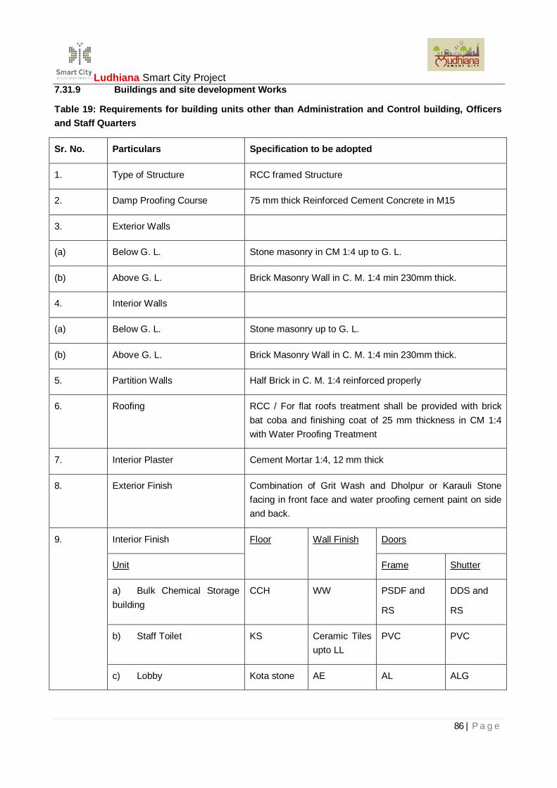
Ludhiana Smart City Project
86 | P a g e
7.31.9 Buildings and site development Works
Table 19: Requirements for building units other than Administration and Control building, Officersand Staff Quarters
Sr. No. Particulars Specification to be adopted
1. Type of Structure RCC framed Structure
2. Damp Proofing Course 75 mm thick Reinforced Cement Concrete in M15
3. Exterior Walls
(a) Below G. L. Stone masonry in CM 1:4 up to G. L.
(b) Above G. L. Brick Masonry Wall in C. M. 1:4 min 230mm thick.
4. Interior Walls
(a) Below G. L. Stone masonry up to G. L.
(b) Above G. L. Brick Masonry Wall in C. M. 1:4 min 230mm thick.
5. Partition Walls Half Brick in C. M. 1:4 reinforced properly
6. Roofing RCC / For flat roofs treatment shall be provided with brickbat coba and finishing coat of 25 mm thickness in CM 1:4with Water Proofing Treatment
7. Interior Plaster Cement Mortar 1:4, 12 mm thick
8. Exterior Finish Combination of Grit Wash and Dholpur or Karauli Stonefacing in front face and water proofing cement paint on sideand back.
9. Interior Finish Floor Wall Finish Doors
Unit Frame Shutter
a) Bulk Chemical Storagebuilding
CCH WW PSDF and
RS
DDS and
RS
b) Staff Toilet KS Ceramic Tilesupto LL
PVC PVC
c) Lobby Kota stone AE AL ALG

Ludhiana Smart City Project
87 | P a g e
Sr. No. Particulars Specification to be adopted
d) Staircase KS WW -
e) Garage CC WW RS
f) Chlorinator room TPT WW RS
g) Chlorination controlroom
TPT WW PSDF DDS
h) Clarifier control room TPT WW PSDF DDS
i) Coagulant dosing room TPT WW PSDF DDS
j) Filter control gallery TPT DT PSDF DDS
k) Backwash pumps andcompressor room with sump
CCH DT PSDF
RS
DDS
RS
l) Workshop CCH WW RS
m) Security cabin TPT WW PSDF DDS
n) Filter Pipe gallery CC Flooring DT PSDF DDS
o) Office TPT AE PSDF FD
p) Archive TPT WW PSDF FD
q) Laboratory KS WW PSDF FD
10. Sanitary
W. C. Indian type Orissa Pan Size 540mm
Urinals Flat Back size 610x400x80 with 25 mm G. I. Waste pipe
Flushing Cistern Low Level 10 liter Capacity, PVC
Wash Basin Flat Back 550x400 mm
CCH – Cement Concrete with Hardener, KS – Kota stone, CC – Cement concrete, TPT – Terrazzo precasttiles, WW – White wash, AE – Acrylic Enamel, DT – Distemper, PSDF – Pressed steel door frame, RS –Rolled shutter, PVC – Polyvinyl chloride, AL – Aluminium,

Ludhiana Smart City Project
88 | P a g e
Table 20: Requirement of Administration and Control building
Sr. No. Type of Building Administration and Control building
Brief Specifications
1 Structure RC framed Structure
2 Masonary in foundation and plinth RR stone masonry in CM 1:4 Orminimum 230 thick Brick Masonry inCM 1:4
3 Damp proof course RCC M15 with water ProofingCompound
4 Masonry in Superstructure Brick Masonary in CM 1:4 230mmthick minimum for external walls and115mm for Internal partition walls
5 Lintels sun-shades etc R.C.C. lintels and sun shades
6 Roofing Treatment Brick bat coba with water proofingcompound min. average 75mm thick.
7 Internal Plaster 12mm CM 1:4 for walls,
12 mm the CM 1:4 for ceiling
8 Exterior Finish Combination of Grit Wash and Dholpuror Karauli Stone facing in front faceand water proofing cement paint onside and back
9 Flooring
a Beneath floor C.C. 1:3:6 base concrete
b Finish Terrazzo Precast (Grey cement) tiles
10 Skirting and dados 10 cm. Height to match flooring
11 Windows (frame, panels, wiregauging, safety bars)
Frame - Assam teak
Inner Shutters - Wired gauge TeakWood frame Outer Shutter - Glazedpanel teak wood shutter

Ludhiana Smart City Project
89 | P a g e
Sr. No. Type of Building Administration and Control building
12 Doors (Frames and shutter) Frame - Assam teak section 150 x 75mm Shutter - Fully paneled teak wooddoor as per specifications andapproved drawing
13 White/ Colour/Cement lime/Decorative Finish
Oil bound Distemper
14 Painting of doors, Windows and walls Synthetic enamel paint
15 Electrification (type of wiring, fittingsand fixture)
PVC Conduit wiring as per drawingand specifications
16 Sanitary and Water Supply
(I) Indian WC In servant quarters and in commontoilets
(ii) European WC In attach toilets with room
(A) Wash Basins In every toilets and in lounge
(iv) Sinks Steel sink
(v) Other accessories As per approved drawing
17 Other Specification PVC frames and shutters in Bathrooms/Toilets
18 Special fitting and fixture
a Fans In every Room
b Tube light In every Room
c Exhaust fans Kitchen / Bathroom
d Coolers In every Room
7.31.10 Clear Water Reservoir, Sump
One clear water reservoir of 1670 m3 capacity is to be constructed with two equal compartments of 835m3
each. The two compartments shall receive water from inlet pipe of WTP. The inlet pipe will split near CWRand shall connect to two compartments with separate inlet pipes and separate valves. The clear waterreservoir shall have total live storage of 1670 m3 above the water level required for pump with vortex free

Ludhiana Smart City Project
90 | P a g e
suction. The CWR roof shall be kept at least 1.00 meter above general ground level. Ventilators shall beprovided in CWR roof at suitable location and all openings of CWR shall be kept covered. The ventilatorsshall be provided with MS grill and wire gauge net to prevent dust entering the clear water reservoirs. Thelive storage depth shall not exceed 5 meters.
7.31.11 Clear Water Pump Station
The clear water pump station building is to be constructed along with Electrical outdoor switchyard. ThePump Station shall have Pump Station, Duty room, Maintenance bay, Toilet block, PLC Control Room etc.
Table 21: The general requirement of pump Station buildings shall be as follows:
Sr. No PARTICULARS SPECIFICATIONS
a) Type of Structure RCC frame Structure
b) Plinth Level Minimum 0.60 meters above finished ground level
c) Minimum Height of building abovefinished floor Levels
As per design
d) Retaining Walls RCC
e) External walls Below Ground Level RR stone masonry in Cement Sand mortar 1:4
f) External walls above Ground Level Brick masonry 230 mm thick in Cement Sandmortar 1:4
g) Internal load bearing Walls and partitionwall around electrical/ battery rooms
Full Brick 230 mm in Cement Sand mortar 1:4
h) Partition walls Half Brick masonry in Cement Sand mortar 1:4
i) Earth Filling for Reclamation ofadditional Land
With suitable earth with compacted to 95% modifiedproctor density
j) Area for PLC Control Room with AC 40 m2 having partitions with aluminum framedglazed panel partitions of height up to lintel level
k) Area for duty room 70 m2
l) External finish Either of water proofing cement paint, sand faceplaster, Dholpur/Karauli stone facing as perapproved architectural plan
m) Plaster
n) Interior Plaster 12 mm thick in Cement Sand mortar 1:4

Ludhiana Smart City Project
91 | P a g e
Sr. No PARTICULARS SPECIFICATIONS
o) Plaster on external Walls 20 mm thick in Cement Sand mortar 1:4, two coats
p) Ceiling Plaster 8 mm thick in Cement Sand mortar 1:4
q) Toilet Ceramic tiles up to lintel level and plaster 20 mmthick in Cement Sand mortar 1:4 above
r) False Ceiling Required in PLC control room
s) Flooring
t) Pump/motor Room Floor Hardener topping with CC base
u) Switchgear Room Kota stone with rubber mat
v) Battery room and Battery charger Room Acid resistant tiles for flooring and dado, Sink andeye wash
w) Operator office space/ duty room/ stairs/ office space/toilets and other areas
Kota stone
x) PLC control room Anti-static PVC flooring with CC flooring base
y) Walk ways GMS Chequered plates
z) Corridors and stairs Kota stone
aa) Painting
bb) Outer building area Cement based paint
cc) Inner areas of pump/motor room, officearea and lobbies
Dry distemper
dd) PLC Control room Acrylic Plastic Emulsion Paint
ee) Battery room Acid resistant paint
ff) Doors
gg) PLC Control room Glass paneled Aluminum Double door shutters withaluminum frame and single panel hinged shutterswith door closures. The first gate shall be providedwith air curtain of appropriate design to ensure dustproofing.

Ludhiana Smart City Project
92 | P a g e
Sr. No PARTICULARS SPECIFICATIONS
hh) Main Entrance Doors Glass paneled Aluminum door shutters withaluminum frame and double panel hinged shutterswith door closures.
ii) Switchgear room/ Battery room 2 hour Fire rated door-HMPS(hollow metal pressedsteel)
jj) Toilet and other areas Pressed steel frame with 40mm thick flush doorsshutter
kk) Windows
ll) On Outer Front Walls and otherwindows opening in main entrances
Glass paneled Aluminum shutters with aluminumframe and double panel shutters. (All windows inPLC room will be fixed without shutters of samespecifications)
mm) Other Windows Steel section window with wire gauge and safetygrill
nn) Cooling Arrangement
oo) Entrance lobby Fans
pp) Office rooms and duty room Fans and Coolers
qq) Pump Station Air washer
rr) PLC Control room Fan and air-conditioners to maintain 24 Ctemperature throughout the year
ss) Drinking water arrangements Taping to be taken from the general waterChlorination system installed for the WTP campussupply.
tt) Treatment and cooling Water cooler 40 liter per Hour and storage capacity80 liters with Zero –B, to be installed
7.31.12 Requirements for Other Area Development Works at Treatment Plant Campus
The campus area of treatment plant is to be developed which includes landscaping, construction ofboundary wall all around the campus, providing interior roads, piping and infrastructure for drinking water,electrification of campus area, providing drainage system, providing gates, development of gardens,plantation of trees etc.

Ludhiana Smart City Project
93 | P a g e
7.31.13 Preparatory Works
The Contractor shall undertake the following works:
i) Approval of architecture, design and drawing of civil structures
ii) Approval of developmental plans and landscaping
iii) Approval of design and drawing of quarters and recreation facilities
iv) Drainage plans and designs
v) Electrification of campus area
vi) Pipe and piping work for potable water in campus area
vii) Other designs / plans required for campus area development
7.31.14 Boundary Wall and Gates
Construction of Boundary wall (average height 1.8 meters above ground and wire fencing of 0.6 meters) allalong the periphery of the acquired land and providing and installation of gates and Gate lights, complete inall respect. The boundary wall shall be made in RR stone masonry in CM 1:4 and shall be pointed in CM1:4. The top of wall shall be provided with 75 mm thick RCC coping. The section of the boundary wall &design of gates shall be got approved from the Employer’s Representative.
7.31.15 Horticulture and Landscaping
Horticulture and Landscaping shall be done according to the topography of the area and should be plannedso as to make the campus a focal point. The open areas leaving expansion requirements must either becovered by tree plantation or must be suitably grassed. Shadow trees must be planted at a maximumdistance of 15 m c/c along the periphery of the campus area and along the roads. The campus must beprovided with gardens, with seasonal flowerbeds and decorative plants.
In case where unsuitable soil is met with, it shall be either removed or replaced or it shall be covered over toa thickness decided by Employer’s Representative with good earth.
The concrete tree guard of 1.5 m height shall be provided as specified by Employer’s Representative.
The planted trees, garden etc. so developed shall be maintained in good condition during the execution andmaintenance period of the Contract without any additional costs. The Contractor shall ensure the safety ofplants and shall take all the activities such as re-plantation, manuring, use of pesticides, mulching, cuttingetc. for growth of trees / plants and maintenance of plants.
7.31.16 Roads, Paths and Hard-standings
A comprehensive road network shall be provided to provide appropriate connectivity of the buildings andutilities, pump Station and around New treatment plant units i.e. main entrance, chlorine tonner shed, bulkchemical storage house, chemical house, clear water pump station, clear water reservoir, and otherimportant units of treatment plant to link with the main road and the existing road network to permit vehicularaccess to each unit of the plant for necessary maintenance, delivery of consumables and personnel access.The internal roads shall be made as specifications and along the road, pre-cast cement concrete kerbs ofapproved shape and size shall be provided.

Ludhiana Smart City Project
94 | P a g e
The road layout shall have due consideration to the storm water drainage system so as to prevent standingwater in the plant area.
Paved pedestrian access ways shall be constructed to provide a network of logical routes interlinking plantareas.
Hard standing areas shall be provided to permit the parking of vehicles involved in the delivery ofconsumables from blocking site roadways during unloading or loading. The road system shall be designedsuch that vehicles involved in the delivery of consumables can follow a continuous route through the plantarea and leave again without going in reverse or carryout complicated maneuvers in order to exit the plant.
Damage to any existing roads on account of their use by the Contractor shall be made good to thesatisfaction of the Employer’s Representative.
7.31.17 Security Cabins
Necessary security cabins shall be provided at each gate. The cabin building shall be of permanent typewith minimum area of each cabin as 10 m2. The detailed requirement is as given in “Requirements forbuilding units other than Administration and Control building”
7.31.18 Workshop
Workshop of minimum area 75 m2 area shall be provided. The detailed requirement is as given in“Requirements for building units other than Administration and Control building”.

Ludhiana Smart City Project
95 | P a g e
7.32 PARTICULAR TECHNICAL REQUIREMENTS – MECHANICAL WORKS
7.32.1 Horizontal Split Casing Centrifugal Pump
It is proposed to provide Horizontal Split Casing Centrifugal pump set of following specifications in all Rawwater, Clear water & Distribution water pumping station.
Contractor has to design these pumps Stations complete for Civil, Mechanical, Electrical & Instrumentationworks. The pump Stations shall be designed to accommodate installation of pump sets for different sectionsas per scope of work and as mentioned below.
7.32.1.1 General Features of Pumps
The clear water pumps shall have the following features:
a) Type of Clear Water Pump Sets,
Horizontal Split Case type pumps with squirrel cage LT Induction Motors of suitable ratings.Pump drive shall be of 0.415 kV rating.
b) NPSH
The NPSH provided by the installation of pumps (NPSHa) shall be at least 0.5 m more thanthat required for the pump (NPSHr) in all conditions of operation.
7.32.1.2 Specifications for Horizontal Split Casing Pumps
The design, manufacture and performance of the pumps specified herein shall comply with therequirements of the applicable Codes and Standards, as follows, but not limited to:
Table22: Specification for Horizontal Split Casing Pumps
No. Standard Title
1 IS 6595 (Part II) Horizontal centrifugal pumps for clear, cold and fresh water.
2 IS 9137 Code for Acceptance Tests for Centrifugal, Mixed flow andAxial pumps.
3 IS 13537 Technical specification for centrifugal pumps - Class 2
4 ISO 5199 Standards of the Hydraulic Institute of USA.
5 ISO 2373 Balancing of impeller.
6 IS 5120 Performance test of pumps
7 IS 11732 Mechanical Balancing
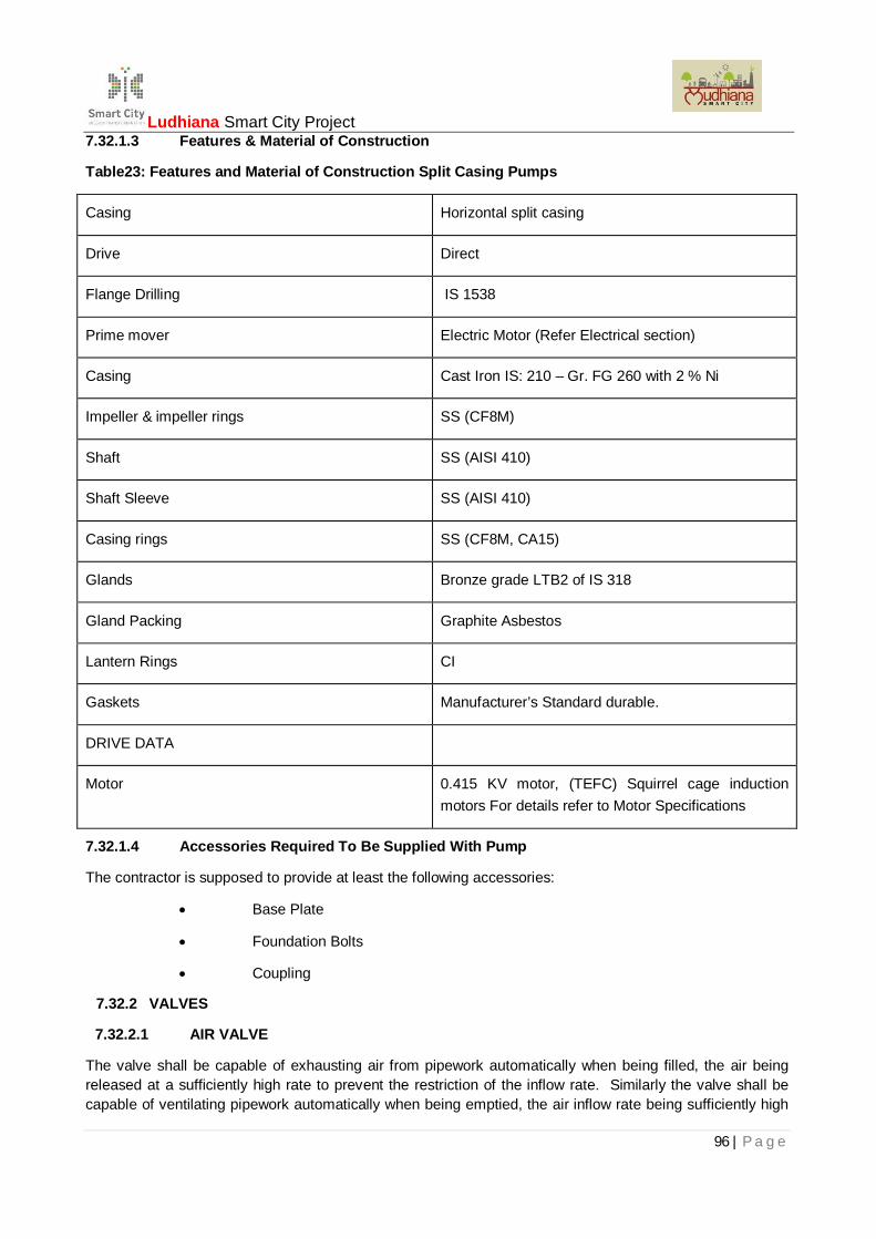
Ludhiana Smart City Project
96 | P a g e
7.32.1.3 Features & Material of Construction
Table23: Features and Material of Construction Split Casing Pumps
Casing Horizontal split casing
Drive Direct
Flange Drilling IS 1538
Prime mover Electric Motor (Refer Electrical section)
Casing Cast Iron IS: 210 – Gr. FG 260 with 2 % Ni
Impeller & impeller rings SS (CF8M)
Shaft SS (AISI 410)
Shaft Sleeve SS (AISI 410)
Casing rings SS (CF8M, CA15)
Glands Bronze grade LTB2 of IS 318
Gland Packing Graphite Asbestos
Lantern Rings CI
Gaskets Manufacturer’s Standard durable.
DRIVE DATA
Motor 0.415 KV motor, (TEFC) Squirrel cage inductionmotors For details refer to Motor Specifications
7.32.1.4 Accessories Required To Be Supplied With Pump
The contractor is supposed to provide at least the following accessories:
Base Plate
Foundation Bolts
Coupling
7.32.2 VALVES
7.32.2.1 AIR VALVE
The valve shall be capable of exhausting air from pipework automatically when being filled, the air beingreleased at a sufficiently high rate to prevent the restriction of the inflow rate. Similarly the valve shall becapable of ventilating pipework automatically when being emptied, the air inflow rate being sufficiently high

Ludhiana Smart City Project
97 | P a g e
to prevent the development of a vacuum in the pipelines. The valve shall also automatically release airaccumulating in pipework during normal working conditions.
Air valves shall thus be designed to automatically operate so that they will;
positively open under internal pressure less than atmospheric pressure to admit air in bulk duringpipeline draining operation;
exhaust air in bulk and positively close as water, under low head, fills the body of the valve during fillingoperation;
not blow shut under high velocity air discharge; and
exhaust accumulated air under pressure while the pipe is flowing full of water
All air valves shall be constructed so that internal working parts which may become necessary for repairsshall be readily accessible, removable, and replaceable without use of special tools and removing the valvefrom the line.
Air valves shall be Kinetic double orifice type as per IS 14845 and tamper proof unless otherwise directedby the Employers Engineer. A buoyant rigid float shall seal the large orifice and the chamber housing shallbe designed to avoid premature closing of the valve by the air whilst being discharged. Small orifice shalldischarge small air volume during operation under full internal pressures. All air valves shall be providedwith isolating sluice valve and flanged end connection.
The aperture of valves must be properly designed for which the Contractor shall submit design calculationsfor necessary approvals before the procurement of valves.
All branched outlets including air valve tees will be provided with one ½” BSP coupling duly plugged formeasurement of pressure in due course. The closing plug shall be in Stainless Steel (AISI 304 orequivalent) with Hex. Head and shall be provided with copper washer for sealing.
Material of construction of air valve shall comply with following requirement.
Body and cover Grade GGG 40
Float Polycarbonate up to 50 NB / SS 304-above 50 NB
Internal Linkages Stainless Steel 304
Gasket, seal ring, sealingface
EPDM
Vent valve Brass
Coating Electro-statically applied epoxy resin- Internally andexternally (min 250 micron)
7.32.2.2 Non-Return Valve/ Rubber Flap Check Valve
i. The valve shall be suitable for mounting on a horizontal pipeline and flow direction shall beclearly embossed on the valve body.
ii. Valves shall possess high speed closing characteristics and be designed for minimum slamcondition when closing.
iii. Dual plate check valves shall conform to API 594 and API 598. They shall have metal tometal sealing. The spring action shall optimize the equal closing rates of each plateespecially when the friction coefficients are uneven due to one plate resting upon one
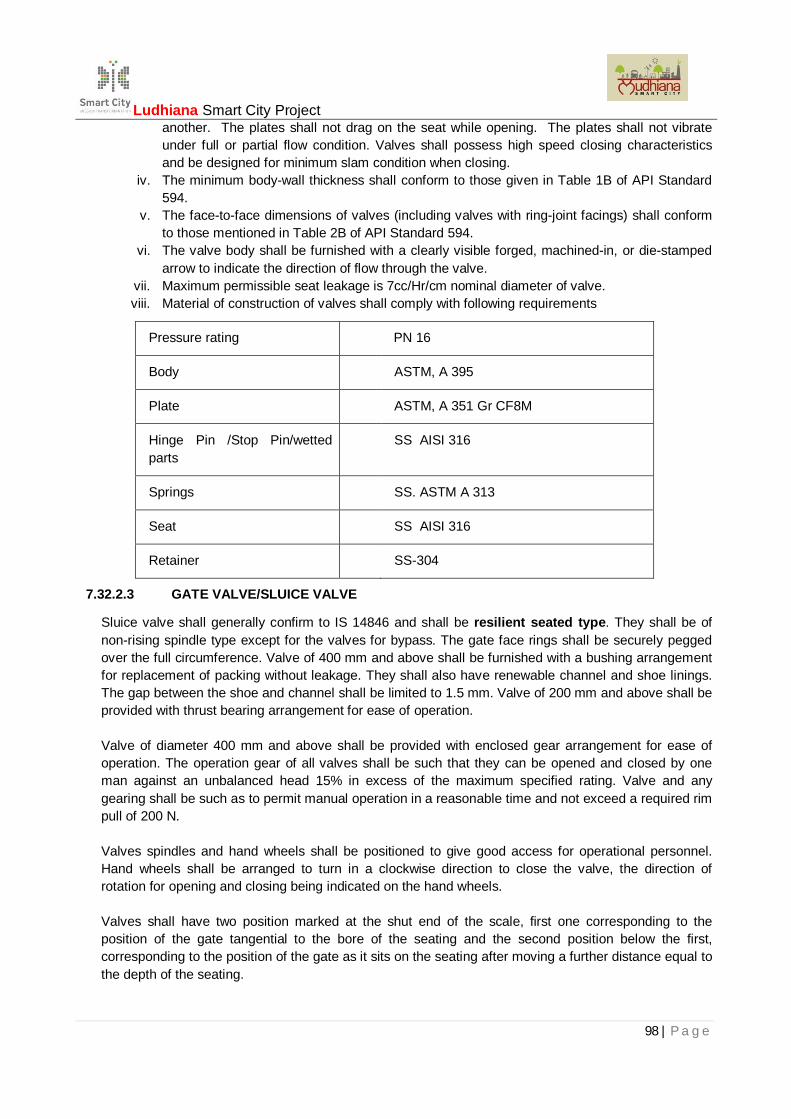
Ludhiana Smart City Project
98 | P a g e
another. The plates shall not drag on the seat while opening. The plates shall not vibrateunder full or partial flow condition. Valves shall possess high speed closing characteristicsand be designed for minimum slam condition when closing.
iv. The minimum body-wall thickness shall conform to those given in Table 1B of API Standard594.
v. The face-to-face dimensions of valves (including valves with ring-joint facings) shall conformto those mentioned in Table 2B of API Standard 594.
vi. The valve body shall be furnished with a clearly visible forged, machined-in, or die-stampedarrow to indicate the direction of flow through the valve.
vii. Maximum permissible seat leakage is 7cc/Hr/cm nominal diameter of valve.viii. Material of construction of valves shall comply with following requirements
Pressure rating PN 16
Body ASTM, A 395
Plate ASTM, A 351 Gr CF8M
Hinge Pin /Stop Pin/wettedparts
SS AISI 316
Springs SS. ASTM A 313
Seat SS AISI 316
Retainer SS-304
7.32.2.3 GATE VALVE/SLUICE VALVE
Sluice valve shall generally confirm to IS 14846 and shall be resilient seated type. They shall be ofnon-rising spindle type except for the valves for bypass. The gate face rings shall be securely peggedover the full circumference. Valve of 400 mm and above shall be furnished with a bushing arrangementfor replacement of packing without leakage. They shall also have renewable channel and shoe linings.The gap between the shoe and channel shall be limited to 1.5 mm. Valve of 200 mm and above shall beprovided with thrust bearing arrangement for ease of operation.
Valve of diameter 400 mm and above shall be provided with enclosed gear arrangement for ease ofoperation. The operation gear of all valves shall be such that they can be opened and closed by oneman against an unbalanced head 15% in excess of the maximum specified rating. Valve and anygearing shall be such as to permit manual operation in a reasonable time and not exceed a required rimpull of 200 N.
Valves spindles and hand wheels shall be positioned to give good access for operational personnel.Hand wheels shall be arranged to turn in a clockwise direction to close the valve, the direction ofrotation for opening and closing being indicated on the hand wheels.
Valves shall have two position marked at the shut end of the scale, first one corresponding to theposition of the gate tangential to the bore of the seating and the second position below the first,corresponding to the position of the gate as it sits on the seating after moving a further distance equal tothe depth of the seating.

Ludhiana Smart City Project
99 | P a g e
All valves on pump suction and delivery piping shall be with electrical actuators. All Sluice valves shallbe open end tested
The body and bonnet shall be of Ductile cast iron of grade GGG-40, wedge with fully encapsulatedEPDM rubber W-270 (approved for drinking water) and seals of NBR. The valves should be withreplaceable stem nut and replaceable sliding shoes. Valve stems shall be of single piece thread rolled.Valve shall have 3 “O” rings of NBR for stem sealing. Gate valve shall be compatible for burriedapplications without valve chamber. Face-to-face dimensions as per BS 5163-89/IS 14846-PD/EN558F4 and flange connections as per IS 1538, Maximum Valve operating torque should be at least40% less than the torque as stated in the standard EN 1074. Electrostatic epoxy powder/liquid coating(EP-P) inside and outside color blue RAL 5005 with minimum coating thickness of 250 microns. TheEPDM rubber & Epoxy Powder should be approved by W 270.
Material of Construction:
Body, Bonnet Ductile Iron GGG 40 (EN-JS- 1030) / Spheroidal Graphite Iron IS:1865 Gr 400/12
Wedge (fully rubber
encapsulated)
Ductile Iron GGG 40 (EN-JS- 1030) / Spheroidal Graphite Iron IS:1865 Gr 400/12 encapsulated with EPDM rubber - W270 approvedgrade.
Spindle/Stem SS: IS: 6603 12Cr13/22Cr 13;AISI 410/AISI 420
Stem Nut Brass
Bonnet Gasket EPDM rubber - W270 approved grade
Internal Fasteners Stainless Steel SS316/304
Stem Sealing Toroidal NBR sealing rings (Min 03 ‘O’ Rings)
Coating Inside & Outside epoxy powder coated; DFT
minimum 250 micron, shade RAL 5005 (BLUE)
7.32.2.4 PLUNGER TYPE FLOW CONTROL VALVES
Plunger type control valve shall be of DI with one piece body of ductile cast iron of grade GGG-40 and allinternal parts of stainless steel. Piston guides shall be of bronze welded overlay & micro-finished andbearing bush of zinc free Bronze. Valve/profile sealing seat shall be in the no-flow zone. Double sealingeffect between the body and the plunger shall be by Quadring Seal (twist free operation). The valve shall bedesigned to operate smoothly throughout the specified flow range without cavitation. Corrosion protectedmedium free bearing in the body by way of double O-ring seal and encapsulated shaft seal. There shall beno obstacles in the main flow passage except the plunger and the attached control cylinders. Plunger shallbe by means of stainless steel crank drive mechanism. Face-to-face dimensions shall be as per EN558-1basic series 15 and 1.5xDN from DN500 and flange connections as per EN1092-2.

Ludhiana Smart City Project
100 | P a g e
Material of Construction:
Body Ductile iron to EN-JS 1030 (GGG-40)
Crank Gear Stainless Steel 304 up to DN600 and Epoxy coated GGG40 for DN700and above.
Plunger Stainless Steel 304
Control Cylinder Stainless Steel 304
Shaft Stainless Steel 420 (1.4021)
Bearing Bush Zinc free Bronze
Piston Guides Bronze overlay welded and micro-finished
Surface Protection Epoxy coating min. 150 microns, color RAL 5005 Blue.
7.32.3 Electric Actuator
The actuators shall be suitable for use on a nominal volt phase Hz power supply and are to incorporatemotor, integral reversing starter, local control facilities and terminals for remote control and indicationconnections housed within a self contained, sealed enclosure.
In order to maintain the integrity of the enclosure, setting of the torque levels, position limits andconfiguration of the indication contacts etc shall be carried out without the removal of any actuator coversover an Infra red interface. Sufficient commissioning tools shall be provided with the actuators and mustmeet the enclosure protection and certification levels of the actuators. Commissioning tools shall not forman integral part of the actuator and must be removable for secure storage/authorised release. In addition,provision shall be made for the protection of configured actuator settings by a means independent of accessto the commissioning tool.
The actuator shall include a device to ensure that the motor runs with the correct rotation for the requireddirection of valve travel irrespective of the connection sequence of the power supply.
Actuators shall be suitable for indoor and outdoor use. The actuator shall be capable of functioning in anambient temperature ranging from 15 to 45 degree C, up to 100% relative humidity.
Actuators for hazardous area applications shall meet the area classification, gas group and surfacetemperature requirements specified in data sheet.
Actuator sizing
The actuator shall be sized to guarantee valve closure at the specified differential pressure andtemperature. The safety margin of motor power available for seating and unseating the valve shall besufficient to ensure torque switch trip at maximum valve torque with the supply voltage 10% below nominal.For linear operating valves, the operating speed shall be such as to give valve closing and opening atapproximately 10-12 inches per minute unless otherwise stated. For 90 valve types the operating timeshould be specified.
Enclosure
Actuators shall be 0-ring sealed, watertight to /IP68 7m for 72hrs, NEMA 4, 6. The motor and all other

Ludhiana Smart City Project
101 | P a g e
internal electrical elements of the actuator shall be protected from ingress of moisture and dust when theterminal cover is removed for site for cabling, the terminal compartment having the same ingress protectionrating as the actuator with the terminal cover removed.
Enclosure must allow for temporary site storage without the need for electrical supply connection.
All external fasteners shall be zinc plated stainless steel. The use of unplated stainless steel or steelfasteners is not permitted.
Motor
The motor shall an integral part of the actuator, designed specifically for valve actuator applications. It shallbe a low inertia high torque design, class F insulated with a class B temperature rise giving a time rating of15 minutes at 40°C(104°F) at an average load of at least 33% of maximum valve torque. Temperature shallbe limited by thermostats embedded in the motor end windings and integrated into its control. Electrical andmechanical disconnection of the motor should be possible without draining the lubricant from the actuatorgearcase.
Motor protection
Protection shall be provided for the motor as follows:
Stall - the motor shall be de-energized within 8 seconds in the event of a stall when attempting tounseat a jammed valve.
Over temperature - thermostat will cause tripping of the motor. Auto-reset on cooling
Single phasing - lost phase protection.
Direction – phase rotation correction.
Gearing
The actuator gearing shall be totally enclosed in a oil-filled gearcase suitable for operation at any angle.Grease lubrication is not permissible. All drive gearing and components must be of metal construction andincorporate a lost-motion hammerblow feature. For rising spindle valves the output shaft shall be hollow toaccept a rising stem, and incorporate thrust bearings of the ball or roller type at the base of the actuator.The design should be such as to permit the opening of the gearcase for inspection or disassembled withoutreleasing the stem thrust or taking the valve out of service. For 90 operating type of valves drive gearingshall be self locking to prevent the valve backdriving the actuator.
Hand operation
A handwheel shall be provided for emergency operation, engaged when the motor is declutched by a leveror similar means, the drive being restored to power automatically by starting the motor. The handwheel orselection lever shall not move on restoration of motor drive. Provision shall be made for the hand/autoselection lever to be locked in both hand and auto positions. It should be possible to select hand operationwhile the actuator is running or start the actuator motor while the hand/auto selection lever is locked in handwithout damage to the drive train.
Clockwise operation of the handwheel shall give closing movement of the valve unless otherwise stated inthe data sheet. For linear valve types the actuator handwheel drive must be mechanically independent ofthe motor drive and should be such as to permit valve operation in a reasonable time with a manual forcenot exceeding 400N through stroke and 800N for seating/unseating of the valve.

Ludhiana Smart City Project
102 | P a g e
Drive bushing
The actuator shall be furnished with a drive bushing easily detachable for machining to suit the valve stemor gearbox. input shaft. Normally the drive bush shall be positioned in a detachable base of the actuator.Thrust bearings, when housed in a separate thrust base should be of the sealed for life type.
Torque and turns limitation
Torque and turns limitation to be adjustable as follows: Position setting range – multi-turn: 2.5 to 100,000 turns, with resolution to 15 deg. of actuator
output.
Position setting range – direct drive part turn actuators: 90 +/-10 , with resolution to 0.1 deg. ofactuator output.
Torque setting: 40% to 100% rated torque.
Measurement of torque shall be from direct measurement of force at the output of the actuator. Methods ofdetermining torque-using data derived from the motor such as motor speed, current, flux etc are notacceptable A means for automatic “torque switch bypass” to inhibit torque off during valve unseating and“latching” to prevent torque switch hammer under maintained or repeated control signals shall be provided.
The electrical circuit diagram of the actuator should not vary with valve type remaining identical regardlessof whether the valve is to open or close on torque or position limit.
Remote valve position/actuator status indication.
Four contacts shall be provided which can be selected to indicate any position of the valve, Provision shallbe made for the selection of a normally closed or open contact form. Contacts shall maintain and updateposition indication during handwheel operation when all external power to the actuator is isolated.
The contacts shall be rated at 5A, 250V AC, 30V DC.
As an alternative to providing valve position any of the four above contacts shall be selectable to signal oneof the following:
Valve opening, closing or moving
- Thermostat tripped, lost phase
- Motor tripped on torque in mid travel, motor stalled
- Remote selected
Actuator being operated by handwheel
Provision shall be made in the design for an additional 4 contacts having the same functionality. Provisionshall be made in the design for the addition of a contactless transmitter to give a 4-20mA analogue signalcorresponding to valve travel for remote indication when required. The transmitter will auto range to the setlimits
Local position indication
The actuator display shall include a dedicated numeric/symbol digital position indicator displaying valveposition from fully open to fully closed in 1% increments. Valve closed and open positions shall be indicatedby symbols showing valve position in relation to the pipework to ensure that valve status is clearlyinterpreted. With main power on the display shall be backlit to enhance contrast at low light levels and shallbe legible from a distance of at least 6 feet (2m).

Ludhiana Smart City Project
103 | P a g e
Red, green, and yellow lights corresponding to open, closed, and intermediate valve positions shall beincluded on the actuator display when power is switched on. The digital display shall be maintained andupdated during handwheel operation when all power to the actuator is isolated.
In addition, the actuator display shall include a separate text display element with a minimum of 32characters to display operational, alarm and configuration status.. The text display shall be selectablebetween English and one of the following languages: Hindi or Marthi. Provision shall be made to upload adifferent language without removal of any covers or using specialized tools not provided as standard withthe actuator. Provision shall be made to orientate the actuator display through increments of 90degres.
Local torque Indication:
The digital display shall be capable of indicating real time torque and valve position simultaneously, bothbeing displayed in 1% increments of valve position and actuator rated torque. In addition torque shall alsobe displayed in horizontal bar graph form.
Integral starter and transformer
The reversing starter, control transformer and local controls shall be integral with the valve actuator suitablyhoused to prevent breathing and condensation. The starter shall be suitable for 60 starts per hour and ofrating appropriate to motor size. The controls supply transformer shall be fed from two of the incoming threephases and incorporate overload protection. It shall have the necessary tappings and be adequately ratedto provide power for the following functions:
Energization of the contactor coils.
24V DC output for remote controls.
Supply for all the internal electrical circuits.
Local controls
The actuator shall incorporate local controls for Open, Close and Stop and a Local/Stop/Remote modeselector switch lockable in any one of the following three positions: local control only, stop (no electricaloperation), remote control plus local stop only. It shall be possible to select maintained or non-maintainedlocal control.
The local controls shall be arranged so that the direction of valve travel can be reversed without thenecessity of stopping the actuator.
Provision shall be made to orientate the local controls through increments of 90 degree.
Control facilities
The necessary control, wiring and terminals shall be provided in the actuator for the following functions:
Open and close external interlocks to inhibit local and remote valve opening and/or closing control. It shallbe possible to configure the interlocks to be active in remote control only.
Remote controls fed from an internal 24V DC supply and/or from an external supply between 20V and 120VAC or 20V and 60 V DC, to be suitable for any one or more of the following methods of control:
Open, Close and Stop control.
Open and Close maintained or “push to run” (inching) control.
Overriding Emergency Shut-down to Close (or Open) valve from a normally closed or opencontact.
Two-wire control, energise to close (or open), de-energise to open (or close).
It shall be possible to reverse valve travel without the necessity of stopping the actuator. The motor startershall be protected from excessive current surges during rapid travel reversal.

Ludhiana Smart City Project
104 | P a g e
The internal circuits associated with the remote control and monitoring functions are to be designed towithstand simulated lightning impulses of up to 2kV.
Provision shall be made for operation by distributed control system utilising the following network systems. Modbus
Profibus
Foundation Fieldbus
DeviceNet
Pakscan
Monitoring facilities
Facilities shall be provided for monitoring actuator operation and availability as follows:
Monitor (availability) relay, having one change-over contact, the relay being energized from the controltransformer will de-energise under any one or more the following conditions: Loss of main or customer 24V DC power supply Actuator control selected to local or stop Motor thermostat tripped Actuator internal fault
Where specified, provision shall be made for contacts to provide discreet indication of one or more of thefollowing:
Remote selected Thermostat trip Actuator fault
Actuator text display indication of the following status/alarms: Closed Limit, open limit, moving open, moving closed, stopped Torque trip closing, torque trip opening, stalled ESD active, interlock active Thermostat trip, phase lost, 24V supply lost, Local control failure Configuration error, Position sensor failure, Torque sensor failure Battery low, power loss inhibit
Integral datalogger to record and store the following operational data: Opening last /average torque against position Closing last /average torque against position Opening motor starts against position Closing motor starts against position Total open/closed operations Maximum recorded opening and closing torque values Event recorder logging operational conditions (valve, control and actuator)
The datalogger shall record relevant time and date information for stored data.
Datalogger data is to be accessed via non-intrusive IrDA communication. Sufficient standard intrinsicallysafe tools shall be provided for downloading datalogger and actuator configuration files from the actuatorsand subsequent uploading to a PC. The actuator manufacturer shall supply PC software to enabledatalogger files to be viewed and analysed.
Ludhiana Smart City Project
105 | P a g e
Wiring and terminals
Internal wiring shall be tropical grade PVC insulated stranded cable of appropriate size for the control and 3-phase power. Each wire shall be clearly identified at each end.
The terminals shall be embedded in a terminal block of high tracking resistance compound.
The terminal compartment shall be separated from the inner electrical components of the actuator bymeans of a watertight seal and shall be provided with a minimum of 2 threaded cable entries with provisionfor a maximum of 4.
All wiring supplied as part of the actuator to be contained within the main enclosure for physical andenvironmental protection. External conduit connections between components are not acceptable.
A durable terminal identification card showing plan of terminals shall be provided attached to the inside ofthe terminal box cover indicating: Serial number External voltage values Wiring diagram number Terminal layout
The code card shall be suitable for the contractor to inscribe cable core identification alongside terminalnumbers.
7.32.4 EXPANSION BELLOWS
The pipe work installation shall be so arranged to offer ease of dismantling and removal of pumps or othermajor items of equipments. Stainless steel AISI 304 expansion bellows which can take radial and axialmisalignment of minimum 1 percent of valve nominal size with tie rods shall be included in the suction anddelivery pipe work of all pumps as well as on delivery header for easy dismantling. All loose flange shall besecured to fixed flanges by suitable tie-bolts. All pipe work shall be adequately supported with purpose-made fittings. When passing through walls, pipe work shall incorporate a puddle flange or other suitablesealing device. The final outlet connection of the pipe work shall match the connecting point of thetransmission main.
7.32.5 PRESSURE REDUCING VALVES
The Pressure Reducing Valve shall reduce higher pressure to lower preset downstream pressureregardless of fluctuating demand or varying upstream pressure head.
Main Valve: The main valve shall be a center guided, diaphragm actuated globe valve of either oblique (Y)or angle pattern, design. The body shall have a replaceable, raised, stainless steel seat ring. The valve shallhave an unobstructed flow path with no stem guides, bearings, or supporting ribs. The body and cover shallbe ductile iron. All external bolts, nuts, and studs. shall be Duplex coated. All valve components shall beaccessible and serviceable without removing the valve from the pipeline.
Actuator: The actuator assembly shall be double chambered with an inherent separating partition betweenthe lower surface of the diaphragm and the main valve. The entire actuator assembly (seal disk to topcover) shall be removable from the valve as an integral unit. The stainless steel valve shaft shall be centerguided by a bearing in the separating partition. The replaceable radial seal disk shall include a resilient sealand shall be capable of accepting a V-Port Throttling Plug by bolting.
Control System: The control system shall consist of a 2-Way adjustable, direct acting, pressure reducingpilot valve, a needle valve, isolating cock valves, and a filter. All fittings shall be forged brass or stainless

Ludhiana Smart City Project
106 | P a g e
steel. The assembled valve shall be hydraulically tested and factory adjusted to customer requirements.The required numbers of switch/contacts meet requirements for PLC system.
Quality Assurance: The valve manufacturer shall be certified according to the ISO 9001 Quality AssuranceStandard. The main valve shall be certified as a complete drinking water valve.
7.32.6 DISMANTILING JOINTS
CI Double flanged Dismantling joints shall be installed in such a manner that valves can be dismantledwithout stress to the joints. Dismantling joints shall be suitable for installation with all valves of differentdiameters.
The dismantling joint shall be designed for a hydrostatic pressure of 10 kg/sq.cm. The sliding flange shall bemachined smooth and shall slide at least 30 mm to disengage fully mating flange. All the fasteners for thedismantling joint shall be of SS 304. These shall be completely leak proof with proper gasket arrangement.Flange dimensions shall conform to latest relevant IS code. Flanged specials shall be supplied with requirednuts, bolts and rubber gaskets. The dismantling joint shall be internally and externally coated with hotapplied (dip) bituminous paint.
7.32.7 Electrically Operated Hoists
Electric hoists shall be complete with hoisting motor, wire rope drum, wire rope, hook, necessary gearing,sheaves, electromagnetic brake for hoisting motion, weather & dust-proof push button station, contractorpanel, all wiring, limit switches, etc.
Electric hoists shall conform to IS: 3938 and shall be suitable for outdoor application. All the parts of thehoist shall be designed to withstand surrounding atmospheric conditions without any deterioration.
Rope drums shall be either cast or welded to sustain concentrated loads resulting from rope pull. Drumsshall be machine grooved right and left with grooves of a proper shape for the rope used.
Gears shall be cut from solid cast or forged steel blanks or shall be of stress-relieved welded steelconstruction or built-up from steel billets and welded together to form a one piece gear section.
Hoist ropes shall be extra flexible, improved plough steel rope with a well lubricated hemp core and havingsix strands of 37 a wires per strand with minimum ultimate tensile strength of 1.6 x 10⁶ KN / Sq.m.
Hooks shall be solid, forged, heat treated alloy or carbon steel of rugged construction of the single hooktype and provided with a standard depress type safety latch.
Hoisting motor shall be equipped with electrically released, spring set, friction shoe type brakes havingtorque capable of holding 125% of the full rated hook load. Brake shall apply when either the motorcontroller or the main power switch is in ‘OFF’ position or in the event of power failure.
Drive motors shall be designed for frequent reversal, braking and acceleration and shall be as per IS: 325.Pendant control switch, controllers and resistors, controls, electrical protective devices, cables andconductors, earthing guards etc. shall be as per IS:3938. Limit switches shall be provided for over-hoistingand over-lowering.
The electric hoists shall be of Class II duty.
25% overload test, speed tests, limit switch tests and brake test shall be conducted for the hoist and trolleyat manufacturer’s works.

Ludhiana Smart City Project
107 | P a g e
7.32.8 Hand Operated Hoists and Trolleys
Manual hoists shall be complete with hand-chain, trolley, pulley block, hook, hand and load chains,brake and other accessories. They shall comply with the latest applicable standards, regulations andsafety codes in the locality where equipment will be installed.
Each hoist shall be operated on a monorail (I-Beam). The factor of safety shall not be less than 5. Theload chain may be heat-treated to give ductility, toughness and conforming to I.S. 3109/B.S. 1663/B.S.3114. The load wheel is to be made from heavy duty malleable castings. The hand chain is to Conformwith B.S. 6405:1984 and hand chain wheel may be made from pressed sheet steel with roller type guarding.Gears shall be cut from solid cast or forged steel blanks or shall be stress – relieved welded steelconstruction. Pinions shall be of forged carbon or heat treated alloy steel. Strength, Quality of Steel, heattreatment, face, pitch of teeth and design shall confirm to BS-436, BS-545 and BS-721. Spur and helicalgears must comply with B.S. 436 and worm with B.S. 721. Bearing must be ball and roller type conformingto I.S. 2513/B.S.2525-32:1954. Proper lubricating arrangements are to be provided for bearings andpinions. The brake for the lifting gear shall be automatic and always in action.
The proof testing of each chain pulley block is to be carried out as per latest applicable standards. Thesafe working load is to be marked in such way that is clearly visible from the operating level.
7.32.9 Manually Operated Travelling Crane
The crane bridge shall consist of a single bridge girder carrying two wheels at each end of the span. Steelused shall be tested quality steel conforming to IS 2062. The girder shall have enough strength to carry thetest load without causing undue stress or deflection.
The long travel bridge wheels shall be rim toughened, heat treated carbon steel or low alloy steel or C.I.They shall be double flanged type. The wheels shall have antifriction ball/roller bearings. The wheels shallbe machined on their treads to match the runway rail section. The bridge shall have a geared shaft andpulley connecting to opposite wheels of the span, to achieve the long travel motion of the bridge, by meansof a chain. The runway rails of adequate strength and rigidity, rail clamps and other accessories formounting the rails and suitable end stops for the bridge shall be supplied by the Contractor.
Trolley and Chain Pulley Block
The chain pulley block shall be operated on the lower flange of the bridge girder.
The load chain shall be made of alloy steel as per IS: 3109. It shall be heat treated to give ductility andtoughness so that it will stretch before breaking. It shall be of welded construction with a factor of safety notless than 5.
The hand chains for the hoisting and traverse mechanism shall hang well clear of the hook and both thechains shall be on the same side. The hand chain wheel shall be made from pressed sheet steel and shallbe provided with roller type guarding to prevent snagging and fouling of the chain.
All the gearing shall be totally encased. Proper lubricating arrangements shall be provided for bearings andpinions. Gears shall be cut from forged steel blanks. Pinions shall be of heat treated alloy steel. Gears shallbe as per BS 436/IS: 4460.
The trolley track wheels shall be rim toughened, heat treated carbon steel or low alloy steel or C.I. and shallbe single flanged and shall have antifriction ball bearings. The wheels shall be machined on their treads tomatch the flanges of the track joints.

Ludhiana Smart City Project
108 | P a g e
The travelling trolley frame shall be made of rolled steel conforming to IS: 2062. The side plates of trolleyframe shall extend beyond wheel flanges, thus providing bumper protection for the wheels. The two sideplates shall be connected by means of an equalising pin.
Axles and shafts shall be made of carbon steel and shall be accurately machined and properly supported.
The lifting hooks shall be forged, heat treated alloy or carbon steel of rugged construction. They shall be ofsingle hook type provided with a standard depress type safety latch. They shall swivel and operate onantifriction bearings with hardened races. Locks to prevent hooks from swivelling shall be provided. Hookshall be as per BS: 2903/IS: 3815
The brake for the lifting gear shall be automatic and always in action. It shall be of screw and friction disctype self-actuating load pressure brake. Brakes shall offer no resistance during hoisting.
Ratchet and Pawl mechanism shall be provided to arrest the full load from lowering due to gravity. Theratchet and pawl shall be of steel, hardened and tempered so as to attain required wear resistance andtoughness.
7.32.10 Electrically Operated Overhead Travelling Crane
The crane shall be electrically operated, bridge type complete with all accessories including down shopconductor, crane rails and fixtures, and shall conform to BS 2573, IS:3177 or relevant internationallyapproved standards.
The crane bridge shall consist of bridge girders on which a wheeled trolley is to run. The bridge trucks andtrolley frames shall be fabricated from structural steel. Access walkway with safe hand railing as is requiredalong the full span length of the bridge girder. Steel shall be tested quality conforming to ASTM A36 exceptthat, plates more than 20 mm thick shall conform to IS: 2062, BS: 4360 or relevant internationally approvedstandards. The bridge shall be designed to carry safely the loads specified in IS: 807, BS: 2573 or relevantinternationally approved standards. All anti-friction bearings for bridge and trolley track wheels, gear boxesand bottom sheaves on hook shall be lubricated manually by hand operated grease pump throughrespective grease nipples.
Wheel base and structural frame of the wheel mounting of the end carriages shall be designed so as toensure that the crane remains square and prevent skewness. Bridge and trolley track wheels shall be offorged steel and shall be double flanged type. The wheel diameter and rail sizes shall be suitable for thewheel loads. The crane rails shall be manufactured from wear resistant austenitic manganese steel.Mountings of the wheels shall be designed to facilitate easy removal for maintenance. Walkways shall be atleast 500 mm clear inside width with a 6 mm thick non-skid steel plate surface. Steel rail stops to preventrails from creeping and trolley from running off the bridge shall be abutted against ends of rails and weldedto the girders. Bridge and trolley stops to match the wheel radius shall be provided before the buffer stops.
All exposed couplings, shafts, gear, wheels, pinions and chain drives etc. shall be safely encased andguarded completely to prevent any hazard to persons working around. All bearings and gears shall have adesign life of 100000 hours. Electro-magnetic and hydraulic thrustor brake shall be provided for the mainhoist. One electro-magnetic brake shall be provided for each of the cross travel and long travel motions.
Hook shall be solid forged, heat treated alloy or carbon steel suitable for the duty service. They shall haveswivels and operate on ball thrust bearings with hardened races. The lifting hooks shall comply with therequirements of IS 8610 or BS: 2903 / BS: 3017 or relevant internationally approved standards and shallhave a safety latch to prevent rope coming off the hook.

Ludhiana Smart City Project
109 | P a g e
Hoist rope shall be extra flexible, improved plough galvanized steel rope with well lubricated hemp core andhaving six strands of 37 wires per stand with minimum ultimate tensile strength of 1.6 X 10⁶ kN/m2 of RightHand Ordinary (RHO) lay construction. The ropes shall have a 6:1 safety factor on the specified safeworking load, and shall conform to IS: 2266. Rope drums shall be grooved and shall be either cast iron orcast steel of or welded steel conforming to IS: 3177, BS: 466 or relevant internationally approved standards.
Gears shall be cut from solid cast or forged steel blanks or shall be stress relieved welded steelconstruction. Pinions shall be of forged carbon or heat treated alloy steel. Strength, quality of steel, heattreatment, face, pitch of teeth and design shall conform to BS: 436, IS: 4460 and BS: 721 or relevantinternationally approved standards.
Name Plate showing the capacity, year of manufacture and rated capacity of hoist, in figures not less than150 mm height, shall be placed on each side of the crane girder.
The maximum deflection under full load shall not exceed 1/900 of the span (as per IS: 3177).
All accessory and auxiliary electrical equipment including drive motors, electrically operated brakes,controllers, resistors, conductors, insulators, current collectors, pendant push button station, protectivedevices, operating devices, cables, conduits, etc. necessary for the safe and satisfactory operation of thecrane shall be provided.
Power to the crane shall be provided by down shop conductors manufactured from high conductivity harddrawn copper. Conductors shall be completely shrouded such that they have no exposed current carryingsurfaces. Pendant type push button station shall be sheet steel enclosed and shall comprise the followingpush buttons and indicating lamps:
a. `Start’ and `Stop’.
b. Long travel - `Right’ and `Left’.
c. Cross travel - `To’ and `Fro’.
d. Hook - `Hoist’ and `Lower’.
e. Red indicating lamp for supply `ON’ indication.
Pendant type push button shall be supported independently of the electrical cable and shall be earthedseparately, independent of the suspension. Automatic reset type of limit switches shall be provided toprevent overtravel for each of the following:
a. For `UP’ and `Down’ motions of the hook.
b. Long travel motion
c. Cross travel motion
Crane structures, motor frames and metal cases of all electrical equipment including metal conduit andcable guards shall be earthed. All motors, brakes, limit switches, panels, drum controllers, resistor unit setsshall be provided with two studs for earthing.
All motors shall be of the quick reversing type with electric mechanical brakes suitable for the dutiesspecified. All movements shall be electrically powered suitable for operating with the hook loaded.Facilities shall be provided for the accurate location of the hook by means of `inching' the cross travel anddown shop travel motions.

Ludhiana Smart City Project
110 | P a g e
Sufficient slings, ropes, shackles, lifting beams, etc shall be supplied to handle all items of plant covered bythe crane. They shall be labelled or marked with the Safe Working Load (SWL) and the purpose for whichthey are intended.
The crane, and all slings, ropes, shackles and other lifting equipment supplied shall be tested by themanufacturer at his works. The tests shall be carried out at 125% of Safe Working Load, and TestCertificates shall be supplied.
The Contractor shall include with the cranes all necessary contactors, control cubicles and protectionequipment necessary to operate the crane and provide adequate electrical protection against overload,phase and earth fault and fail-safe protection in the event of an interruption in the power supplies. Allaccess ladders and platforms necessary to carry out maintenance and repairs shall be provided andinstalled by the Contractor.
All electrical equipment shall be fully tropicalised.
Site tests shall be carried out by the Contractor who shall supply the necessary materials for the test load.The test load shall be removed from site by the Contractor after successful tests have been carried out.

Ludhiana Smart City Project
111 | P a g e
7.33 PARTICULAR TECHNICAL REQUIREMENTS – ELECTRICAL WORKS
7.33.1 General
The scope of work includes design, equipment selection, manufacture, inspection at Contractor's or hisSub-Contractor's works, supply, installation (including storing, unloading and transferring the material /equipment to Contractor’s storage area, maintaining equipment / material in safe custody and assemblingthe elements of the equipment and installing at the place of work), testing and commissioning of the plantequipment/ electrical system on ‘Design Build& Operate’ basis and dismantling of existing electricalequipment and handed over the existing equipment to Employer’s Representative at the location asdirected by the Employer Representative. After successful commissioning and trial run of the plant, it shouldbe handed over to the Employer. The Contractor shall also be responsible for Operation &Maintenance(O&M) of the plant for 5 years after it is formally taken over by the Employer. The Contractor shall submittheir design calculations/ drawings based on ‘Design criteria for electrical equipment/system’ for Employer’sreview and approval. These specification covers substations, transformers, HV/LV switchboards, energyefficient motors, soft starters, capacitors, HV and LV power cables and control cables, and other alliedequipment, etc. along with the specifications for workmanship, laying cables, lighting system, earthingsystems, lightning protection etc. for this water supply project. It shall be the responsibility of the Contractorto design the electrical system based on the selection of the mechanical equipment.
The Bidder shall make his own estimate of sizes, ratings and quantities for, substation equipment, all plantitems and miscellaneous systems such as earthing, lightning protection, lighting, auxiliary powerdistribution, etc. Design of electrical system (i.e. Substation, transformers and other electrical equipment)shall be based on Stage-I (i.e. year up to 2033) only. However, facility for upgrade/ expansion of allequipment to cater Stage-II load shall have to be considered during design-engineering stage. Sufficientspace in the switchyard and switchboard/ control room shall be provided for expansion/ up-gradation ofswitchyard / electrical equipment/ switchboard for Stage-II load. It should be clearly understood that theContract will be on ‘Design Build & Operate’ basis and no variation will be allowed for items of works notforeseen or omitted by the Bidder at the bidding stage, except where specifically indicated in the biddocuments.
All equipment offered shall comply with the requirements specified in the latest editions of applicable Indian/International Standards and shall also comply with the good engineering practices.
Contractor shall design the electrical system on the basis of ‘Design Criteria’ and to be submitted forEmployer’s approval. Contractor shall incorporate any changes/ suggestions in the drawings to suit siteconditions and design criteria and standard engineering practice and resubmit for approval to Employer’sRepresentative.
The Contractor shall possess the valid electrical Contractor’s license of appropriate class from theconcerned statutory bodies governing the area of work place. The Contractor shall fully comply with therelevant statutory rules and regulations.
All type (as applicable), routine and acceptance tests shall be conducted in the presence of Employer/Employer’s Representative / Third Party Inspector on all the equipment as per latest applicable IS/IEC at noextra cost. Typical type test reports for other equipment shall be submitted by the Contractor for approval byEmployer/ Employer’s Representative.

Ludhiana Smart City Project
112 | P a g e
All commissioning tests shall be carried out in the presence of Employer/ Employer’s Representative andapproval for the same shall be obtained before commissioning and installation. All test reports shall beproperly maintained by the Contractor duly approved by the statutory bodies and shall be handed over tothe Employer after completion of the job. All instrument and accessories required for testing andcommissioning of the equipment specified herein shall be provided by the Contractor at no extra cost to theEmployer.
Liaison with State Electricity Board and other Government organization/ statutory bodies for obtainingPower supply/ other clearance shall be Contractor’s scope. After completion of installation work, theContractor shall arrange for inspection and obtain approval from the concerned statutory bodies. Any feesthat are to be paid to such statutory bodies for testing, inspection or calibration shall be paid by theContractor. Any modification / revision in the equipment / installation of equipment as required by thestatutory bodies shall be carried out by the Contractor. All such costs / fees for revisions / modificationsshall be deemed to be included in the prices of supply, installation, testing and commissioning of equipmentas quoted by the Contractor.
7.33.2 Transformer Size selection Criteria
The transformer size shall be determined from the estimation of the simultaneous maximum demand basedon the power rating of motors and other loads and their operating / running periods.
The design shall be based on maximum nos. of main motors working and the corresponding auxiliary loadsincluding WTPs shall be considered for sizing of transformer.
Appropriate values of load factor, diversity factor, power factor and efficiency shall be considered for eachtype of load. Improvement in power factor due to capacitors shall not be considered. Five percent (5%)contingency shall be added to the simultaneous maximum demand thus calculated and the next standardsize of transformer as per IEC shall be selected.
Two such transformers shall be provided for 100 % redundancy at each site. The design calculations fortransformer sizing shall be subject to the approval of the Employer’s Representative.
7.33.3 Electrical System for Proposed Intake works, Raw water system and 10 MLD WaterTreatment Plant
A new reliable 11kV connection shall be taken for proposed Intake works, Raw water system and WTP nearSidhwan canal.
The new substation shall be capable for feeding the entire load for proposed WTP and Clear water pumpstation (up to Stage-II requirement) with adequate voltage and power quality.
Incoming 11 KV supply shall be step down by distribution transformers, which in turn shall feed the main LVindoor switchboard. 100% redundant transformers are proposed (i.e. one working + one standby) to feedthe entire load of the proposed pump system. The transformer neutral is to be earthed to limit the earth faultcurrent. The transformers (and the cables to the LV switchboard) shall be suitable for outdoor application.
Necessary metering, protection and indication/ annunciation are to be provided on all the switchboards

Ludhiana Smart City Project
113 | P a g e
7.33.4 Electrical System for Proposed Water Distribution Pump Stations
A new reliable 11kV connection shall be taken for proposed Water distribution pump stations at Leisurevalley and Rose garden. The new substation shall be capable for feeding the entire load of proposed WDS(upto Stage-II requirement) with adequate voltage and power quality.
Outdoor Substation located adjacent to proposed Leisure valley and Rose garden water distribution pumpstations shall be provided with RCC foundation. 11 kV overhead lines to be terminated on a 4-pole structurethrough suitable HV disconnections with earthing switch and all metering and protection arrangements andLightning arresters shall be provided on the incoming lines.
Incoming 11 KV supplies shall be step down on distribution transformers, which in turn shall feed the mainLV indoor switchboard. 100% redundant transformers are proposed to feed the entire load of the proposedpump station. The transformer neutral is to be earthed to limit the earth fault current. The transformers (andthe cables to the LV switchboard) shall be suitable for outdoor application.
Both transformers shall also have capability of supply power to the LV auxiliary loads of proposed Leisurevalley and Rose garden water distribution pump stations, which includes loads such as electrical valveactuators, control and instrumentation panels, EOT crane, LV auxiliary motors and indoor and outdoorlighting load.
Main LV switchboard shall be located in electrical room of Water Distribution Station receive power from thetransformers to feed the individual loads. Suitable space in the Pumping station shall be taken for futureexpansion of main LV switchboards. Outgoing Feeders for both VFD & Motor starters shall be taken in mainLV Switchboard.
LV capacitor banks with control panel consisting of automatic power factor correction (APFC) relay are to beproposed across each LV bus section of each LV switchboard.
Necessary metering, protection and indication/ annunciation are to be provided on all the switchboards
7.34 PARTICULAR TECHNICAL REQUIREMENTS - INSTRUMENTATION, AUTOMATION ANDCONTROL SYSTEM WORKS
7.34.1 GENERAL
This section outlines the particular requirements for the instrumentation, automation and control systems.Unless specified in this section to the contrary instrumentation Plant provided by the Contractor andworkmanship shall comply with the General Instrumentation, Automation and Control RequirementChapters of these Requirements.
7.34.2 THE SCOPE and Battery Limits
The scope of instrumentation, control and automation (ICA) works shall comprise the design, manufacture,programming and configuration, off site testing, delivery to site, installation and erection, testing,commissioning, setting to work and provision of documentation for a complete supervisory, instrumentation,control and automation system including the interfaces required to provide monitoring and control for a safeand efficient operation of plant, equipment and system.
The Contractor shall submit and obtain approval of the instruments and the system from the employerbefore beginning the detailed control system design.
The minimum scope of work shall include but not limited to:

Ludhiana Smart City Project
114 | P a g e
MASTER CONTROL CENTRE (MCC) at proposed Water Treatment Plant
Design, supply, install, test and commission a dual redundant control system. PLC, RTU & SCADA shallinclude but not limited to process controller including its central process units (CPUs), communicationmodules, input-output (I/O) modules, control networks, operator workstations with 32” LED display,engineering workstation with 60” LED display and printers.
This system shall be designed in order to control, operate and monitor the following:
- New water treatment plant
- Raw water reservoirs and pumping station
- Treated Water reservoirs and Pumping station
Field Instrumentation
Design, supply, install, test and commission field instrumentation for the Entire Water supply systemincluding WTP, RWPS and CWPS.
Instrumentation Schedule
A listing of the basic instrumentation and control system to be supplied, installed, tested and commissionedunder this water supply scheme shall include, but not be limited to, the list given in Table below.
Service Type of Instrument Instrument Function
I. Flow Measurement
i. Flowmeasurementnear plant inlet
Open channel flow meter(Ultrasonic)
Transmission, Indication andrecording of flow rates andtotalisation of flow.
ii. Filtered water flow Electromagnetic flow meter– full bore
Transmission, Indication andrecording of flow rates andtotalisation of flow.
iii. Backwash waterflow
Electromagnetic flow meter– full bore
Transmission, Indication andrecording of flow rates andtotalisation of flow.
iv Flowmeasurement ofwaste water
Electromagnetic flow meter– full bore
Transmission, Indication andrecording of flow rates andtotalisation of flow.
v. Flowmeasurement ofair for filter wash
Anubar Transmission, Indication andrecording of flow rates andtotalisation of flow.
vi Rate of flow forfilter bed
Ultrasonic Transmission, Indication andrecording of flow rates and

Ludhiana Smart City Project
115 | P a g e
Service Type of Instrument Instrument Function
totalisation of flow.
vii Bulk water Flowmeasurement atall DMA’s
Electromagnetic flow meter– full bore
Transmission, Indication andrecording of flow rates andtotalisation of flow.
II. Level Measurement
i. Water level inclear water sump
Ultrasonic levelmeasurement
Monitoring of water level,continuous measurementtrending of data and initiationof alarms
Conductivity type levelswitches for high and lowlevel detection
Tripping of pumps at low waterlevel and generating an alarm
ii. Water level inBackwash watertank
Ultrasonic level measuringsystem
Monitoring of water levelcontinuous measurement,trending of data and initiationof alarms
Conductivity type of levelswitches for high and lowlevel detection
Tripping of pump at high waterlevel and starting at low level,and generating alarms
iii. Water level inclarified waterchannel
Ultrasonic level measuringsystem
Monitoring of water levelcontinuous measurement andalarm
iv. Water level in filterwater channel
Ultrasonic level measuringsystem
Monitoring of water levelcontinuous measurement andalarm
v. Level in coagulantsolutionpreparation tanks
Ultrasonic level measuringsystem
Monitoring of level in coagulantsolution preparation tanks andgenerating alarm
Conductivity type of levelswitches
As a backup protection to levelsensing
vi. Level in coagulantservice tanks andPE dosing tank
Sight glass Indication of level in coagulantservice tanks and PE dosingtank

Ludhiana Smart City Project
116 | P a g e
Service Type of Instrument Instrument Function
Vii Level in thickenedsludge tank
Ultrasonic levelmeasurement
Monitoring of water levelcontinuous measurementtrending of data and intimationof alarm
viii Level in CWR’s,and UGSR’s
Ultrasonic levelmeasurement
Monitoring of water levelcontinuous measurementtrending of data and intimationof alarm
Conductivity type of levelswitches for high and lowlevel detection
Tripping of pump at high waterlevel and starting at low level,and generating alarms
III Pressure Measurement
i. Head lossmeasurementacross filter bed
DP transmitter and panelmounted indicator system
Differential level transmitter forfilter bed for measuring headloss across bed
ii. Pressure in BWwater header
Pressure measurementsystem consisting of apressure transmitter andpanel mounted indicatorsystem
Pressure transmission,monitoring and generating analarm
iii. Pressure in BW airheader
Pressure measurementsystem consisting of apressure transmitter andpanel mounted indicatorsystem
Pressure transmission,monitoring and generating analarm
iv. Pressuremeasurement onblower outlet
Pressure gauge Pressure monitoring of air;manually
V Sludge transferpump
Pressure gauge Pressure monitoring
vi Centrifuge feedpump
Pressure gauge Pressure monitoring
Pressuremeasurement on
Pressure measurementsystem consisting of a
Pressure transmission,monitoring and generating an

Ludhiana Smart City Project
117 | P a g e
Service Type of Instrument Instrument Function
pumping mains pressure transmitter andpanel mounted indicatorsystem
alarm
IV. Water Parameter Monitoring Instruments
i. pH of water forraw water, clarifiedwater and filteredwatermeasurement
pH measuring instrument Continuous monitoring of pHand generating alarm.Trending of data
ii. Turbiditymeasurement
Turbidity meter Continuous monitoring ofturbidity and generating alarm.Trending of data
iii. Chlorine residualmeasurement
Chlorine residual analyzer Continuous monitoring ofresidual chlorine andgenerating alarm. Trending ofdata
V. Miscellaneous
i. Chlorine leakagein chlorine /cylinder room
Chlorine leak detector Monitoring Cl2 in airgenerating alarm at instance ofleakage and switching onchlorine neutralization system
ii. Operating panelfor filter bed
Console Manual/automatic controllingwashing sequence of bed
iii Operating panelforClariflocculators
Clarifier Panel Manual/automatic control ofclariflocculators
VI. Automation
I Filter bed PLC based instrumentcontrol panel
Monitoring, controlling,operation automatically, semiautomatically
ii Clariflocculators PLC based instrumentcontrol panel
Monitoring, controlling,operation automatically, semiautomatically

Ludhiana Smart City Project
118 | P a g e
Service Type of Instrument Instrument Function
iii Chemical dosing PLC based instrumentcontrol panel
Monitoring, controlling,operation automatically, semiautomatically
iv Chlorination PLC based instrumentcontrol panel
Monitoring, controlling,operation automatically, semiautomatically
v Sludge handling PLC based instrumentcontrol panel
Monitoring, controlling,operation automatically, semiautomatically
vi Raw and Clearwater pumpingstations
PLC based instrumentcontrol panel
Monitoring, controlling,operation automatically, semiautomatically
vii SCADA Software + Hardware For monitoring, operation &control of plant
viii Informationtechnology
Software + Hardware For inter connection raw waterpumping station, clear waterpumping station, WTP &UGSRs & Water distributionpump stations
ix RTU panels Hardware + Software For data transmission ofremote field instruments likeflowmeters, pressuretransmitters and leveltransmitters to MCC.
Communication Network
Interface equipment to enable communication between field instruments, PLC’s, RTU’s, and SCC SCADAat WTP’s and UGSRs and Water distribution pump stations.
Supply, installation, testing commissioning of RTU’s along with GPRS at UGSR’s to transmit flow, level andpressure data to MCC for monitoring and control.
The communication equipment required to achieve this interfacing complete with all required accessoriesshall be supplied under this contract.
Data Acquisition and processing
The data acquisition, processing and interfacing with the Master Control Centre of entire water supplyscheme of ABD area is covered under this package.

Ludhiana Smart City Project
119 | P a g e
System Console
Control room furniture(system console) include but not limited to control console for placing dual redundantworkstations and two printer compartments, desk for one engineering workstation, ODMS workstation andprinter compartment and chairs .The system console design shall be submitted to the Employer for priorapproval.
The Contractor shall be responsible for the design of each instrumentation and plant monitoring system,including the selection and design of appropriate transducers (on approval by the Employer’srepresentative), transmitters, signal conditioning devices, indicators, alarm system programmable devices,communications, cable system etc. The Contractor shall take account in his design of all installation andenvironmental conditions prevailing at the site.
7.34.3 Design Requirements for Instrumentation, Control, Automation and SCADA Systems
The instrumentation, control, automation SCADA installations shall fully comply with design standards,regulations and the material and workmanship requirements of the Specification.
The electrical plant installations associated instrumentation control and automation systems shall alsocomply with and be tested in accordance with the latest edition of BS 7671 or equivalent Indian standards.
All equipment and materials incorporated in the system shall be selected, designed and rated to operateunder the defined performance duties and specified site conditions and to maintain a high level ofoperational reliability.
The instrumentation control and monitoring system equipment and materials shall have an operational life ofnot less than 15 years, unless otherwise approved by the Engineer.
7.34.4 Design criteria for Instrumentation, Control, Automation and SCADA Systems
7.34.4.1 Instrumentation System
a) Electronic instruments shall utilize solid state electronic components, integrated circuits,microprocessors, etc., and shall be of proven design.
b) all instruments shall be suitable for continuous operation;
c) all digital outputs shall be volt free;
d) all instrumentation systems for use out of doors shall be protected to IP 65 for sensors andtransmitters, while enclosures under submersible conditions shall be protected to IP68;
e) all analogue displays shall be of the digital type with no moving parts utilizing back lit liquidcrystal diode technology;
f) For transmitting instruments, output signal shall be 4-20 mA DC linear having two wire system.
g) Unless otherwise stated, overall accuracy of all measurement systems shall be ±0.5% ofmeasured value, and repeatability shall be ±0.5%.
h) After a power failure, when power supply resumes, the instruments and associated equipmentshall start working automatically.
i) The instruments shall be designed to permit maximum interchangeability of parts and ease ofaccess during inspection and maintenance.

Ludhiana Smart City Project
120 | P a g e
j) The instruments shall be designed to work at extremes of the ambient conditions oftemperature, humidity, and chlorine contamination that may prevail. The instruments shall begiven enough protection against corrosion.
k) Lockable enclosure shall be provided for the field mounted instruments wherever required.
l) All field instruments, and cabinets / panel-mounted instruments shall have tag plates / nameplates permanently attached to them.
m) The performance of all instruments shall be unaffected for the ±10% variation in power supplyvoltage and ±5% variation in frequency simultaneously.
n) All wetted parts of sensors shall be made out of non-corrosive material capable of working withchlorine content of 5 ppm.
o) For all instruments (transmitting analogue signals) installed in the field, surge protection devices(SPDs) shall be provided at both ends of the connecting cable for the protection against staticdischarges / lightning and electromagnetic interference.
p) Pressure transmitters shall be provided with two valve manifold and a test port, so that in situcalibration can be carried out.
q) Two wire transmitters shall be provided with on-line test terminals.
r) The ranges of all instruments shall be suitable for the application in the process.
s) Instruments of similar type shall be of same make for appropriate inventory of spares, ease ofmaintenance and training.
7.34.4.2 PLC System
PLC shall be provided as a Hot-Standby configuration to perform combinational and sequential logicfunctions, status monitoring and reporting functions with counter and timer facilities.
PLC Panel interrogation power supply should be fully redundant.
PLC shall comprise of necessary processors, input/output (I/O) modules, communication interface modulesand man-machine interface (MMI) required to perform the desired functions.
Each PLC shall have memory protected built in historical archiving/data logging of system alarms & eventsand process variables. Data logger shall be able to log data based on time or an event PLC shall haveenough memory allocated to allow 200,000 time and data stamped discrete and /or analog values to bearchived. The historical archive shall allow the oldest data to roll off the system as memory is used keepingthe 200,000 most current data points available. Process point time stamping frequency shall be selectablewithin the configuration software. It shall be possible for the archived data to be exported in CSV formatallowing use with standard spreadsheet and data software applications
PLC shall have the following attributes as a Hot-Standby configuration.
- carry out sequential logic implementation for operations of plant;
- carry out computation and interfacing for data acquisition, data storage and retrieval;
- it shall accept downloaded program from a programmer;
- it shall have different functional modules to perform the desired functions;

Ludhiana Smart City Project
121 | P a g e
- it shall scan the inputs in time cycles and update the status of its outputs.
7.34.4.3 RTU System
RTU shall be designed in accordance with this specification. The RTU shall be of proven design and suitedfor water supply and distribution SCADA applications.
RTU design should aim to minimize power consumption and heat generation. It should be designed to workin remote installation by being of robust physical construction with immunity to electrical noise.
The RTU shall be assembled from modular units, for example, power supply module, CPU andcommunications module, communication interface modules and modules for input/output purposes. I/O andserial cards shall be able to be arranged in the RTU rack in any order.
Modules shall be interconnected via a suitably robust plug and socket method. It shall not be necessary tounscrew individual wires/cables, both internal RTU wiring and I/O wiring, to replace faulty modules. Thefailure of one module will not affect the performance of any other module.
A marshalling terminal area shall be incorporated with each RTU to provide terminations for field cables.This area can be located in the RTU cubicle itself for an RTU replacement but for new locationsthere should be a separate marshalling cubicle. The RTU and marshalling cubicles shall normally be boltedtogether to form a 2-bay cubicle suite. A separation plate may be located between the cubicles.
The RTU and the cubicles shall be designed to accommodate the actual number of input/outputs, plusspare capacity.
7.34.4.4 SCADA System
The SCADA shall be a fully dual redundant server integrated microprocessor based control and dataacquisition system which will monitor, control, display, record and trend all assigned plant and water supplynetwork inputs and outputs. The main process monitoring and control shall be by means of Visual DisplayUnit (min. 60 inch. LED monitor) based process operator workstations that shall be located in the centralcontrol room.
SCADA/HMI system shall be designed and implemented such that the failure of a central processor or HMIconsole does not inhibit continuous automatic control of the plant. In the event of such a failure, historicaldata shall be recoverable to a condition where a worst-case maximum of 15 minutes of historical data islost.
Failure of a single outstation or communications to that outstation shall not affect control or operation of anyother outstation, unless the failed outstation provides essential data to another outstation, in which case thenon-failed outstations shall revert to a fail-safe mode.
7.34.5 Functional Design Specification (FDS, Sequence of Operation)
The Contractor shall propose the details of the sequence of operation for the water supply system, watertreatment plant and pumping stations through careful study of the water supply scheme proposed. Further,the contractor shall be solely responsible to comply with any change/additional processes during thecontractors design stages.
The Contractor shall submit a complete functional design specification (FDS) for approval by the Employerwithin 3 months of the award of the contract.

Ludhiana Smart City Project
122 | P a g e
Functional design specification (FDS) for the SCADA system shall be combined with the FDS forinstrumentation, control and automation to form a complete document and shall comply with thespecification of the FDS for instrumentation, control and automation. This document shall serve as theprimary mechanism by which the Employer may confirm that the Contractor possesses an accurateunderstanding of the system and its control requirements. The Contractor is encouraged to obtain anynecessary clarifications and to suggest refinements to the control descriptions contained in thisSpecification.
The FDS shall include a detailed block diagram of the PLC, RTU & SCADA system with a description of thecommunications scheme to be provided. The FDS shall include operational details of the SCADA systemwhich have an effect on plant operations, such as power failure response, communication failure response,and automatic shut-down and start-up of the system.
The FDS shall include a description of the interface of the SCADA system witfDJBh any existing or plannedfuture DAC (Digital Access Carrier) equipment.
The Contractor shall submit a preliminary FDS and obtain approval before the system architecture design isfinalized or detailed design takes place. The Contractor shall formally notify the Employer for approval ofany amendments or additions to the approved FDS. The final FDS shall be submitted for approval beforesubmission of the factory acceptance test definition documents. The Contractor should take note of theimportance of this obligation.
The FDS shall comprise an overall description of the system, its functioning and control, and a detaileddescription of each section of the control system covering modes of operation, manual overrides, set-pointand parameter selection and adjustment. The detailed description shall include a step-by-step controldescription which defines the function of each piece of equipment and each control action and interlock,including details of the program in each programmable item.
The FDS shall describe the ‘fail-safe’ features incorporated into the design for the event of failure of a plantitem or system, or loss of an input signal affecting a control loop or process sequence.
The FDS shall describe control actions taken and monitoring functions which remain available during apower failure, and any automatic controls or sequencing which take place during system start-up and shut-down.
The FDS shall be presented in a clear and precise manner and shall include figures or drawings whereappropriate.
7.34.6 Reference Standards
Unless otherwise approved, instrumentation shall comply with relevant quality standards test proceduresand codes of practice collectively referred to as Reference Standards including those listed in GeneralInstrumentation, Automation and Control System in accordance with the requirements detailed elsewhere inthis specification.
7.34.7 Specifications for online water quality monitoring systems
This section covers the specification required for online water quality sensors to be provided under thecontract. The system should be user friendly that operates & analyze in minimum interval without any needof reagents, chemicals, consumables with low maintenance and calibration requirement. It should becapable of integration with the SCADA system.

Ludhiana Smart City Project
123 | P a g e
Online multi-parametric pH, Conductivity/TDS, Turbidity, free Chlorine at various points of water distributionand the reservoirs.
The system proposed should have adequate channels to accommodate above measurements and shouldhave capacity to display up to total 10 parameters to future-proof the system as it is not envisaged toupgrade the controller for next few years.
The system should have capability to accommodate any additional sensors viz. ORP, Dissolved Oxygen,Nitrite as may be required by the project authorities from time to time.
Parameters will be monitored at different location as mentioned below:
Water quality monitoring station will contain the sensors and equipment to measure the below mentionedparameters.
1. pH2. Turbidity3. TDS4. Conductivity5. Residual Chlorine6. Flow7. Pressure
7.34.7.1 Multi-parameter Controller System Specifications:
It should be equipped with the following minimum features:
USB-interface for data transfer, upgrading firmware etc.Control unit with keys and toggle switch for the quick selection of software functionsWith colour graphic display with backlightWith integrated backup controller functionInput voltage 90 - 264 VAC 50/60 HzLine power consumption approx. 25 VAMax. power delivery 18 Watt6 galvanically separated current outputs (0/4-20 mA) that can be assigned arbitrarilyMODBUS communication protocol for the data integration with PLC and SCADAWith Sensor ID recognitionHigh EMC interference immunityIntegrated lightning protectionShould have the latest features of highly advanced Multi parameter Controller havingcapability of handling at least 4 sensors in a single controller configuration and more as andwhen required.Display should be with improved reading precision through special backlit graphic displayEasy User Intuitive operating keys: including keys for functions such as: Measurement,calibration, set/system settings, additional keys for: confirmation/switching menu O.K. (OK),Escape (ESC) etc.Internal integrated Data logger with minimum data memory for up to 500,000+ data sets

Ludhiana Smart City Project
124 | P a g e
The Controller should be able to power all the sensors and terminals or accessories attachedto it without having to need any additional power sources in the system for increasedprotection against lightening and possible electromagnetic interference.
The system should start automatically after the power is reset to the system (in case of powerfailure).The controller should be low power consuming with consumption of less than 5W.Sensors connected to the system shall be automatically detected and initialized.No extra system configuration should be needed for substitute / replacement sensors.The system should have Service mode for cleaning/calibration/maintenance activities.It should be possible to download the data via the USB interface an extremely fast dataexchange to USB memory stick.
The system should be fully programmable with multiple levels of access control with help ofElectronic-Key for data security and protection against non-authorized access to avoid anytampering or changes to the system configuration by unauthorized access.The controller should store the sensor configurations and calibrationsThe controller should have Logbook to record the dataThe supplier should provide the firmware update free of cost as and when they are availablefor the life time of the system.The system should have a status LED that gives reliable and fast information regardingfunction and status of system. And the Controller/controller should show a LED for diagnosticpurposes on the front. This LED should show normal and malfunctions of the system at aglance.Data Output to Control System: The System should have the capability to transmit therequired 4-20 mA Analog Outputs as a minimum.In addition to above, the system should have ability to output Profibus, Modbus/RS 485, RS232, LAN, GPRS, GSM compatible signals in future with addition of respective module asand when required.The system should be able to operate on AC Power (100-240 AC)Ambient Conditions Operating temperature: -4 °C … +55 °CStorage temperature: -10 °C … +65 °CHousing Material – Non corrosive e.g. Acrylonitrile-Styrene-Acryloesterpolymer or betterProtection Rating IP 66 / equivalent to NEMA 4X for controllerElectromagnetic Compatibility: EN 61326, Class B; FCC Class A, EMC for indispensableoperationIntegrated Lightning Protection: According to EN 61326 enhanced overvoltage protection forthe entire system, implemented in each component
7.34.7.2 Sensor Specifications:
i. pH Sensor Specifications: Integrated temperature measurement and compensation should be provided in the pH sensor. Sensor check function to detect broken glass of the pH electrode. The pH sensor should have galvanically separated input. Calibration history should be stored automatically in the sensor.

Ludhiana Smart City Project
125 | P a g e
Sensor calibration can be done in the laboratory or field. The pH combination electrodes should require very little maintenance and there should be no
electrolyte replacement.
Technical Specifications:
- Measuring Range: pH – 4.00- 12.00 at least considering the wastewater environment- Signal Output –Digital- Sensor Check function should be available in the pH sensor- Power Consumption: less than 0.5 Watt- Temperature Sensor should be integrated in the pH sensor- Temp Compensation: -5 to +50 Deg C- Transient Voltage Protection should be integrated in the sensor- Sensor body: Stainless Steel or better- protection type : IP 68 for both Sensor and Cable- Sensor Cable Length: 7 meter
ii. Conductivity/TDS Sensor:
The sensor should have high measuring accuracy 4-electrode design with no influence bypolarization effects at higher conductivity values.
Should have measuring range of 0.00 µS/cm to 500 mS/cm.
TDS and salinity measurement should also be integrated.
Technical Specifications:-
- Measuring Range: Conductivity: 0-500 mS/cm; Salinity: 0-70; TDS: 0-2000 mg/l- Signal Output –Digital- Power Consumption: less than 0.5 Watt- Temperature Sensor should be integrated with conductivity measurement.- Temp Compensation: -5 to +50 Deg C- Max Pressure for Sensor: 10 Bar- Input Power: Powered by the Controller- Transient Voltage Protection should be integrated into the sensor- Sensor Body: Titanium or equivalent- Protection type : IP 68 for both Sensor and Cable- Sensor Cable Length: 15 meters
iii. Turbidity Analyzer Specification:Turbidity sensor shall be connected to the multi-parameter measuring system. It shall be equipped with thefollowing features:
Automatic cleaning system or better maintenance less and consumables free cleaning system Scattered light measurement Scratch-resistant sapphire measurement windows Sensor monitoring function Integrated lightning protection With screw / plug connector for connection of the sensor connection cable

Ludhiana Smart City Project
126 | P a g e
Measuring range (selectable): 0 to 1000 NTU Process variation coefficient according to DIN 38402 part 51:in the range up to 2000 FNU
less than 1 % Repeatability or repeating limit DIN ISO 5725 or DIN 1319: less than 0.015 % or min. 0.006
FNU
Temperature range:Operating range: 0 °C ... 60 °CStoring range: -5 °C ... 65 °C
Material:Measurement window: SapphireEnclosure shaft: V4A stainless steel 1.4571
Type of protection : IP 68 (with the sensor connection cable connected)
iv. Residual Chlorine Analyzer specification:
Module for measuring free chlorine in water for use on raw/treated water panel with controllerUseable in media with constant pH between 6-8.
Chlorine electrode:
Range: 0-10 mg/l Resolution: 0.01 mg/l pH-Range: pH 6-8 Electrochemical principle Temperature range: 5 - 45°C
Material:
PVC, Silicone, Polycarbonate
Current of water needed:
In flow thru armature approx. 30 l/h.
Maximal pressure: Armature with electrode: max. 1 bar overpressure
v. Level Sensor:
Ultrasonic type level transmitters shall be microprocessor based and shall use digital signal processingtechnique for signal conditioning. The transmitter shall have facilities for storing the echo profile,manipulation of the echo profile to remove noise, multiple profile-averaging etc.
The transmitter shall have the capability to use statistical filtering techniques, wherever required, tocompensate for rotating agitator blades or to suppress false signal due to heavy dust or fill-streaminterference.
Ludhiana Smart City Project
127 | P a g e
In very dusty applications or in silo/ bunker, etc. filling applications, high power and long range (i.e., lowfrequency) transducer shall be used to overcome the detrimental effect of the dust. This type of instrumentshall not be used for level measurement in process medium consisting of particles of sizes (- 6 mmdiameter).
Ultrasonic transmitter shall be have 4-20mA (24V DC loop powered) / Field bus compatible and possible tocalibrate through hand held universal and field bus configurator also.
The sensor shall have in-built temperature sensor for ambient temperature compensation.
Chemical compatibility of the sensor material with the process material shall be ensured, to avoid corrosion.
In applications, where material build-up on the sensor is expected, the transducer shall have suitable build-up compensation (i.e. repetitive, pulsating displacement at its face shall be used to remove the materialbuild-up).
Ultrasonic transmitters shall be supplied along with necessary calibration software, noise suppressionsoftware, plug connector, cable, profibus to RS232C modem etc. for calibration/ noise suppression throughlaptop / desktop PC.
Adjustable mounting arrangement shall be provided for proper aiming of ultrasonic sensors. Suitableprotection box for ultrasonic level sensor shall be provided.
Provision for the nitrogen purging facility in the ultrasonic sensor shall be provided for cleaning the buildupof the material.
Pipe insert of min. dia 200mm shall be available for mounting the level transmitter on top of the tanks.Necessary mounting brackets for mounting the level transmitter in the tank shall be provided.
Range: 0 to 15 meters
Temperature: -20 to +60° C
Temperature compensation: Built-in -20 to +60° C
Spread: 3°, 6°
Enclosure: IP 68 / NEMA 6P (submersible to 10 m / 30 ft. of water)
Measuring accuracy: Better than 0.2%
Analog output: Active 4-20mA galvanically isolated, max. loop resistance 500Ohms
Digital output: Two SPDT electromechanical relays. (max 50V DC / 1 A)
Transmitter Enclosure rating: IP 65 / NEMA 4X
vi. Electromagnetic flow meter:
Selection of Electromagnetic flow meters shall be decided based on the following:
All magnetic flow meters shall be SMART type. Magnetic flow meters, which are to be installed in thecontrol, alarm & interlocking circuits, shall have 4-20mA DC output (24V DC loop powered) / profibuscompatibility along with Data loggers and battery back up.
Liner material shall be selected based on service. Generally, for liner material PTFE shall be used.

Ludhiana Smart City Project
128 | P a g e
If gases are entrained in the liquid, meter shall be installed in vertical process line.
While installation it shall be ensured that flow tube is always completely filled with liquid.
Straight length requirement of minimum 5D to 10D in the upstream and 2D to 3D in the downstream shallbe provided for water services. However, for other services it shall be designed as per manufacturer’srecommendation.
The tube material shall be SS 316, with PTFE linner and SS-316 Electrode. The coil housing should alsobe of SS-316.
Installation of electromagnetic flow meters shall be avoided near large conducting surface e.g. metalsurfaces. (Large surface may interfere with magnetic field of instrument thus affecting accuracy).
Pulsed DC excitation shall be provided for field excitation of Electro Magnetic Flow Meter. Power & signalcircuits of magnetic flow meter shall be completely isolated from each other.
Minimum one no. of grounding ring for metallic pipelines and minimum two nos. of grounding rings for non-metallic pipelines shall be used for installing the magnetic flow meter.
Selection and sizing of electro-magnetic flow meters flow characteristics published by the manufacturersshall be followed. Allowable flow velocity shall be considered based on the specific merit of the service,allowable pressure drop, and cost effectiveness and as per manufacturers recommendation, however thesize of flow meter shall not be less than the size of conduit where it is proposed.
Accuracy of magnetic flow meter shall be ± 0.3% or better. Local display shall be calibrated in engineeringunit.
A bypass line with isolation valves shall be provided for the magnetic flow meters so that magnetic flowmeters can be cleaned on line.
Sensor & transmitter of magnetic flow meters shall be mounted separately.
Magnetic flow meter shall be provided with built-in auto zero facility for ensuring stable zero point.
Separate earth pit shall be provided exclusively for earthing of magnetic flow meters. Preparation of suchearth pits shall be governed by the general methodology as described in IS 3043, 1991 or relevantinternational standards.
Necessary calibration unit for checking the electronic unit of magnetic flow meter shall be provided.
Enclosure class of magnetic flow meters shall be IP 68.
Pulsed DC excitation for better accuracy and measurement signal stability shall be used. Power & signalcircuits of magnetic flow meters shall be completely isolated from each other.
While installation, it shall be ensured that flow tube is always completely filled with liquid and at no time theflow meter shall be empty.
Flow meter shall be provided with necessary ground ring, fasteners, gaskets, reducer / expander, matchingflange including straight line pipes (Inlet run: 5D min & Outlet run: 3D min / as per manufacturerrecommendation). Also spool pieces of length flange to flange for replacing the flow meters duringmaintenance shall be provided.

Ludhiana Smart City Project
129 | P a g e
Pressure data logger capable of transferring data via GPRS/SMS communication. Input pressure range of 0- 20 bars, accuracy ± 0.5%, and repeatability ± 0.1%, with re-zero function for offsetting. Memory must benot less than 50,000 readings, and can be set in cyclic or start-stop (block). Logging interval can be set 1second, 1 min, 15mins, 30mins, hourly etc. Capable to export data to comma-separated values (csv) fileformat or Excel spreadsheets. Software Supports statistical data (average, maximum, mean and standarddeviations). Ingress Protection rating of IP68, with minimum battery life of 5 years.
Data loggers must be compatible with the Employer’s telemetry software
Mounting: Flange
Materials: Housing: Painted carbon or stainless steel
Liner: Hard rubber, soft rubber or PTFE
Electrode: Stainless steel 1.4571
Built-in grounding electrode: required
Accuracy: Better than ± 0.25%
Temperature: 0 to 50° C
Enclosure: IP 67 (with gel potting IP 68)
Analog output: One active 4 - 20 mA, galvanic isolated (max. 800 )
Digital output: One voltage-free, electromechanical relay (max. 50 V DC / 1 A)
One optically isolated (max. 50 V AC / V DC / 120 mA)
Transmitter Enclosure rating: IP 67
Power supply: 24 V AC
Data logger: Display 160,000 logs with date, time, value and daily totals
vii. Communication and Data Presentation/ Display
The controller should be interfaced with a GSM/GPRS communication modem to seamlessly transmit thedata from remote plants to a central location over a pre-defined interval.
The communication to the system should be two way for ability to view settings and make changes to theconfiguration over the air, as and when required.
The data should be received at a central location and should be displayed there in real-time in graphicaland tabular format. The software as a minimum should have ability to print reports, archive data and make itavailable for export as a CSV file. The system should also have facility to generate alarm when set pointsare exceeded

Ludhiana Smart City Project
130 | P a g e
7.35 PARTICULAR TECHNICAL REQUIREMENTS - PIPE LINE WORKS
7.35.1 High Density Polyethylene Pipes (HDPE Pipes) Scope
This specification covers the requirements for successfully designing, manufacturing, supplying, laying,jointing and testing at works and site of High Density Polyethylene Pipes used for water supply.
7.35.2 Applicable Codes
The manufacturing, testing, supplying, laying, jointing and testing at work sites of HDPE pipes shall complywith all currently applicable statutes, regulations, standards and Codes. In Particular, the followingstandards, unless otherwise specified herein, shall be referred. In all cases the latest revision of the Codesshall be referred to. If requirements of this Specification conflict with the requirements of the standards /Codes, this Specification shall govern.
Others Codes not specifically mentioned here but pertaining to the use of HDPE pipes form part of theseSpecifications.
IS: 4984 High Density Polyethylene Pipes for Water Supply
IS: 2530 Methods of test for polyethylene moulding materials and polyethylene compounds
IS: 5382 Rubber sealing rings for gas mains, water mains and sewers. Methods for randomsampling
IS: 7328 High density polyethylene materials for moulding and extrusion
IS: 7634 Laying & Jointing of Polyethylene (HDPE) Pipes
IS: 9845 Method of analysis for the determination of specific and/or overall migration ofconstituents of plastics material and articles intended to come into contact withfoodstuffs
IS: 10141 Positive lists of constituents of polyethylene in contact with food stuffs,pharmaceuticals and drinking water.
IS: 10146 Polyethylene for its safe use in contact with foodstuff, Pharmaceuticals and drinkingwater.
IS 4905 1968 Methods for random sampling
IS 8360 (part- I): 1977 “Specification for Fabricated High Density Polyethylene Fittings forPotable Water Supplies – General Requirements”
IS 8360 (part- II) :1977 “Specification for Fabricated High Density Polyethylene Fittings for PotableWater Supplies – Specific Requirements for 90 Deg. Tee”
IS 8360 (part- III) :1977 “Specification for Fabricated High Density Polyethylene Fittings for PotableWater Supplies – Specific Requirements for 90 Deg. Bends”
IS 8008 (part-I): 2003 “Injection Moulded / Machine High Density Polyethylene (HDPE) Fittings forPotable Water Supplies –Specification – General Requirements for fittings”
7.35.3 Designation
Pipes shall be designated as per IS 4984, according to the grade of material, followed by pressure ratingand nominal diameter, for example, PE 100 PN 10 DN 200 indicates a pipe pertaining to material grade 100having a pressure rating 1.0 MPa and outside nominal diameter 200 mm.

Ludhiana Smart City Project
131 | P a g e
7.35.4 Colour
• For the purpose of identification of the pipes, each pipe shall contain minimum three equispacedlongitudinal strips of width 3mm (min) in blue colour, these strips shall be coextruded during pipemanufacturing and shall not be more than 0.2 mm in depth. The material of the strip shall be of thesame type of resin.
• All HDPE Pipes of the same size, same pressure rating and same grade and also manufactureessentially under similar conditions of manufacture, shall constitute a lot.
7.35.5 Materials
The material used for the manufacturer of pipes should not constitute toxicity hazard, should not supportmicrobial growth, should not give rise to unpleasant taste or odor, cloudiness or discoloration of water. Pipemanufacturers shall obtain a certificate to this effect from the manufacturers of raw material by anyinternationally reputed organization as per the satisfaction of the engineer in charge.
7.35.6 Raw Material
Raw material used to manufacture the HDPE pipes shall be 100% virgin PE compound or Natural black PEresin confirming to IS: 4984, IS: 7328 and ISO: 4427 for this a certification has to be given by the resinmanufacturer as per clause 3.2.3 of IS: 4984. The resin proposed to be used for manufacturing of the pipesshould also comply with the following norms as per ISO 9080
(a) The resin should have been certified by an independent laboratory of international repute for havingpassed 10,000 hour long term hydrostatic strength (LTHS) test extrapolated to 50 years to showthat the resin has a minimum MRS of over 10MPa. Internal certificate of any resin manufacturer willnot be acceptable.
(b) Certificate for having passed the full scale rapid crack propagation test as per ISO 13478. Highdensity Polyethylene (HDPE) used for the manufacture of pipes shall conform to designationPEEWA-45-T-006 of IS 7328. HDPE conforming to designation PEEWA-45- T-012 of IS 7328 mayalso be used with the exception that melt flow rate (MFR) shall not exceed 1.10 g/10 min. Inaddition the material shall also conform to clause 5.6.2 of IS 7328.
(c) The specified base density shall be between 941.0kg/ m³ and 946.0kg/ m³ (both inclusive) whendetermined at 27°C according to procedure prescribed in IS7328 The value of the density shall alsonot differ from the nominal value by more than 3 kg/ m³ as per 5.2.1.1 of IS 7328. The MFR of thematerial shall be between 0.41 and 1.10 (both inclusive) when tested at 190°C with nominal load of5 kgf as determined by method prescribed in IS 2530. The MFR of the material shall also be within± 20 percent of the value declared by the manufacturer.
(d) The resin shall be compounded with carbon black. The carbon black content in the material shall bewithin 2.5 ±0.5% and the dispersion of carbon black shall be satisfactory when tested as per IS2530.
7.35.7 Anti-oxidant
The percentage of anti-oxidant used shall not be more than 0.3 percent by mass of finished resin. The anti-oxidant used shall be physiologically harm less and shall be selected from the list given in IS 10141

Ludhiana Smart City Project
132 | P a g e
7.35.8 Reworked Material
No addition of Reworked/ Recycled Material from the manufacturer‘s own rework material resulting from themanufacture of pipes is permissible and the vendor is required to use only 100% virgin resin compound.
7.35.9 Effect of nature of soil on pipe performance
The bidder shall provide certified information, as per IS code of practice about the performance of HDPEpipes, if laid in corrosive soils, below water table or under saturated conditions or rocky strata, etc. Thenecessary precautions, as per IS code of practice, to be taken like painting or bitumen coating or providingspecial bedding or crossing any feature under hanging, etc to encounter such conditions shall be mentionedand accounted for in the bid cost by the bidder
7.35.10 Maximum Ovality of Pipe
The outside diameter of pipes, tolerance on the same and ovality of pipe shall be as given in table 2 of IS4984. Ovality shall be measured as the difference between maximum outside diameter and minimumoutside diameter measured at the same cross section of the pipe, at 300 mm away from the cut end. Forpipes to be coiled the ovality shall be measured prior to coiling. For coiled pipes, however, re-rounding ofpipes shall be carried out prior to the measurement of ovality.
7.35.11 Wall Thickness
The minimum & maximum wall thickness of pipe for the three grades of materials, namely PE63, PE80, andPE100 shall be as given in table 3, 4, & 5 respectively in IS:4984.
7.35.12 Length of Straight Pipe
The length of straight pipe used shall be more than 6 m or as agreed by engineer in charge. Short lengthsof 3 meter (minimum) up to a maximum of 10% of the total supply may be permitted.
7.35.13 Coiling
The pipes supplied in coils shall be coiled on drums of minimum diameter of 25 times the nominal diameterof the pipe ensuring that kinking of pipe is prevented. Pipe beyond 110mm dia shall be supplied in straightlength not less than 6m.
7.35.14 Workmanship / Appearance
Pipes shall be free from all defect including indentations, delaminating, bubbles, pinholes, cracks, pits,blisters, foreign inclusions that due to their nature degree or extent detrimentally affect the strength andserviceability of the pipe. The pipe shall be as uniform as commercially practicable in colour opacity, densityand other physical properties as per relevant IS Code or equivalent International Code. The inside surfaceof each pipe shall be free of scouring, cavities, bulges, dents, ridges and other defects that result in avariation of inside diameter from that obtained on adjacent unaffected portions of the surface. The pipeends shall be cut clearly and square to the axis of the pipe.
7.35.15 Marking of Pipes
The internal and outer diameter, length, wall thickness, tolerances and other dimensions of pipes shallbe as per relevant clauses of IS 4984:1995 (inc. all amendments) and any amendments made to tilldate. Each straight length of pipe shall be clearly marked and should cover the following:
a. The manufacturers name and trade mark,

Ludhiana Smart City Project
133 | P a g e
b. Outside diameter,
c. IS classification,
d. Stiffness class
e. Lot number / Batch number
7.35.16 Handling, Transportation Storage and Lowering of pipes
During handling, transportation, storage and lowering, all sections shall be handled by such means and insuch a manner that no distortion or damage is done to the section or to the pipes as a whole.
The following procedures should be followed so as to eliminate potential damage to pipes and fittings and tomaintain maximum safety during unloading, lifting and lowering.
Pipes must not be stored or transported where they are exposed to heat sources likely to exceed60oC.
Pipes shall be stored such that they are not in contact with direct sunlight, lubricating or hydraulic oils,petrol, solvents and other aggressive materials.
Scores or scratches to a depth of greater than 10% or more of wall thickness are not permissible; anypipes having such defects should be strictly rejected.
PE pipes should not be subjected to rough handling during loading and unloading operations. Rollersshall be used to move, drag the pipes across any surface.
Only polyester webbing slings should be used to lift heavy PE (>315mm) pipes by crane. Under nocircumstances, chains, wire ropes and hooks be used on PE pipes.
Pipes shall not be dropped to avoid impact or bump. If any time during handling or during installation,any damage, such as gouge, crack or fracture occurs, the pipe shall be repaired if so permitted by thecompetent authority before installation.
During coiling care should be taken to maintain the coil diameter at or above the specified minimum toprevent kinks. Coiling shall be done when the pipe attains the ambient temperature from the extruder.In uncoiling or recoiling care should be taken that sharp objects do not scour the pipe.
When releasing coils, it must be remembered that the coil is under tension and must be released in acontrolled manner. The end of the coil should be retained at all times, then the straps releasedsteadily, one at a time. If the coil has bands at different layers of the coil, then they should bereleased sequentially starting from the outer layers. The amount of the energy locked up in the coilwill depend on the size of the pipe, the SDR of the pipe, and the size of the coil.
Straight lengths should be stored on horizontal racks giving continuous support to prevent the pipetaking on a permanent set
Bare coils shall be wrapped with hessian cloth for long distance (> 300Kms) transportation. The truckused for transportation of the PE pipes shall be exclusively used of PE pipes only with no othermaterial loaded – especially no metallic, glass and wooden items. The truck shall not have sharpedges that can damage the Pipe.

Ludhiana Smart City Project
134 | P a g e
Pipes manufactured at factory are to be carried to the site of work directly or stacked suitably andneatly along the alignment/road side/elsewhere near by the work site or as directed by the Engineer.
Damages during transit, handling, storage will be to the Contractor‘s account and replacement forsuch pipes has to be made by the Contractor without any extra cost as directed by the Engineer.
7.35.17 Lowering, Laying of Pipes
Each pipe shall be thoroughly checked for any damages before laying and only the pipes which areapproved by the Engineer shall be laid. While installing the pipes in trenches, the bed of the trenchshould be level and free from sharp edged stones. In most cases, the bedding is not required, as longas the sharp and protruding stones are removed, by sieving the dug earth, before using the same abackfill material. While laying in rocky areas suitable bed of sand or gravel should be provided. The fillto about 10 to 15 cm above the pipe should be fine sand or screened excavated material. Where hardrock is met with, bed concrete M15, 15 cm or 20cm thick sand bed as approved by the engineer maybe provided
As PE pipes are flexible, long lengths of fusion-jointed pipes having joints made above ground can berolled or snaked into narrow trenches. Such trenches can be excavated by narrow buckets.During thepipe laying of continuous fusion jointed systems, due care and allowance should be made for themovements likely to occur due to the thermal expansion/contraction of the material. This effect ismost pronounced at end connections to fixed positions (such as valves etc) and at branchconnections.
Care should be taken in fixing by finishing the connections at a time the length of the pipe is minimal(lower temperature times of the day). For summer time installations with two fixed connection points,a slightly longer length of PE pipe may be required to compensate for contraction of the pipe in thecooler trench bottom. The final tie-in connections should be deferred until the thermal stability of thepipeline is achieved.
The flexibility of polyethylene pipes allows the pipe to be cold bend. The fusion jointed PE pipe is alsoflexible as the plain Pipe. Thus the total system enables directional changes within the trench withoutrecourse to the provision of special bends or anchor blocks. However, the pipe should not be coldbend to a radius less than 25 times the OD of the pipe.
The Installation of flanged fittings such as connections to sluice/air/gate valves and hydrant tees etc.,requires the use of stub ends (collars/flange adaptors complete with backing rings and gaskets. Careshould be taken when tightening these flanges to provide even and balance torque.
Provision should be made at all heavy fittings installation points for supports (such as anchoring of theflange in the soil) for the flange joint to avoid the transfer of valve wheel turning torque on to the PEflange joint.
PE pipe is lighter than water. Hence care should be taken for normal installations where there couldbe a possibility of flooding of the trench thus the trench shall be kept free of water till the jointing hasbeen properly done. When flooded, some soils may lose cohesiveness, which may allow the PE pipeto float out of the ground. Several design checks are necessary to see if groundwater flotation may bea concern. Obviously, if the pipeline typically runs full or nearly full of liquid, or if groundwater isalways below the pipe, flotation may not be a significant concern.

Ludhiana Smart City Project
135 | P a g e
However, weights by way of concrete blocks (anchors) are to be provided so that the PE pipe doesnot float when suddenly the trench is flooded and the soil surrounding the pipe is washed away. Thussite conditions study is necessary to ensure the avoidance of flotation.
Pipe embedment backfill shall be stone-free excavated material placed and compacted to the 95%maximum dry density.
7.35.18 Jointing of Pipes
The pipe shall have a jointing system that shall provide for fluid tightness for the intended serviceconditions. Appropriate jointing for HDPE pipe as per IS 4984 shall be selected considering site and workingcondition, pressure and flow of liquids.
i. All joints shall be made as per relevant IS code, in practice, and manufacturer’s installation manual orinstructions. All joints shall be tested for their performance as per provisions made in relevant IS codes.Joints that show leakage will not be accepted. After backfilling and inspection, if groundwater infiltrationis observed through joints into the laid water line, then such joints shall be sealed by the bidder at noextra cost to the owner.
ii. Pipe surfaces to be joined must be free of dust, dirt, oil, moisture and other foreign material. If required,use of chemical such as dichloro-methane, methyl ethyl-ketone or mechanical cleaner may be carriedout.
iii. Jointing of pipes and fittings shall be done by Electro fusion/ Butt fusion welding to joint two ends ofHDPE pipes. ISO 12176-1:1998 Plastics pipes and fittings - Equipment for fusion jointing polyethylenesystems - Part 1: Butt fusion and ISO 12176-2:2000Plastics pipes and fittings - Equipment for fusionjointing polyethylene systems - Part 2: Electrofusion shall be followed for the same.
iv. However to join HDPE with other pipe/valves flanges/ mechanical joint compression fittings shall beused confirming to ISO 14236:2000 Plastics pipes and fittings - Mechanical-joint compression fittingsfor use with polyethylene pressure pipes in water supply systems
7.35.19 Bedding, Backfilling and Compaction
7.35.19.1 Bedding
In case of sandy strata no separate bedding is required. However the bottom face / trench bed where pipeshall be placed shall be compacted to provide a minimum compaction corresponding to 95% of maximumdry density. The pipe bedding should be placed so as to give complete contact between the bottom of thetrench and the pipe.
7.35.19.2 Back Filling
Backfilling should be placed in layers not exceeding 15cm thickness per layer, and should be compacted toa minimum of 95% maximum dry density. The refilling should be done on both sides of pipe together &height difference in earth fill on each side should not be more to cause lateral movement of pipe.
Most coarse grained soil are acceptable. This may comprise of gravel or sand.However silty sand, clayeysand, silty and clayey gravel shall not be used unless proposed to be used in conjunction with gravel orclean sand.
It is very important that the pipe zone backfill material does not wash away or migrate in to the native soil.Likewise, potential migration of the native soil in to the pipe zone backfill must also be prevented.

Ludhiana Smart City Project
136 | P a g e
Heavy earth moving equipment used for backfilling should not be brought until the minimum cover over thepipe is 90 cm in the case of wide tracked bulldozers or 120 cm in the case of wheeled roaders or rollercompactors.
7.35.19.3 Compaction
Vibratory methods should be used for compaction. Compaction within distances of 15 cm to 45 cm from thepipe should be usually done with hand tempers. The backfill material should be compacted not less than95% of maximum dry density.
7.35.20 Fittings & Specials
Injection moulded HDPE fittings shall be as per IS: 8008 (Part I to IX). All fittings/specials shall be injectionmoulded at factory only. General requirement of Injection moulded HDPE fittings conforming to IS: 8008Part I.
Bends
HDPE bends shall be conforming to IS: 8008 Part II Specifications.
Tees
HDPE Tees shall be conforming to IS: 8008 Part III Specifications.
Reducers
HDPE Reducers shall be conforming to IS: 8008 Part IV Specifications.
Flanged HDPE Pipe Ends
HDPE Stub ends shall be square ended conforming to IS: 8008 Part I & VI Specifications. Stub ends will bewelded on the pipe. Flange will be of slip on flange type as described below:
Slip-On Flanges
Slip-on flanges shall be metallic flanges covered by epoxy coating or plastic powder coating. Slip-on-flangesshall be conforming to standard mating relevant flange of valves, pipes etc. Nominal pressure rating offlanges will be PN10.
7.35.21 Welding Procedure
Jointing between HDPE pipes and specials shall be done as per the latest IS: 7634 part II. Method ofjointing between the pipes to pipes and pipes to specials shall be with fusion welding using automatic orsemi automatic, hydraulically operated, superior quality fusion machines which will ensure good qualityfusion welding of HDPE pipes. If approved by the concerned Engineer, jointing with PP compression fittingsmay be carried out for smaller diameters of PE pipes (up to 110mm).
7.35.22 Tests to Establish Portability of Work
Pipe specimen shall be subjected to tests specified below in order to establish the suitability of these pipesfor use in carrying potable water:
I. Smell of the extractII. Clarity of the colour of the extractIII. Acidity and alkality

Ludhiana Smart City Project
137 | P a g e
IV. Global migration UV absorbing material Heavy metalsV. Un-reacted monomers (styrens) and Biological tests
7.35.23 Hydraulic Testing
Pipes shall be given different hydraulic tests for ensuring quality of manufacture as per relevant IS andspecification mentioned elsewhere in the bid documents. Hydro pressure testing shall be done on thecompleted pipe length for a minimum pressure of 1.5 times the designed pressure for retaining period of 4hours, and as mentioned in IS 4984 –1995 including its latest amendments. The acceptance criteria forhydrostatic test are no permanent deformation of any part of the pipeline fitting or equipment’s and thereshall not be any leakage through any of the joints
7.35.24 Measurement
The net length of pipes as laid or fixed shall be measured in running meters correct to a cm. Specials shallbe excluded and measured and paid separately under the relevant item. The portion of the pipe at the joints(inside the joints) shall not be included in the length of pipe work. Excavation, refilling, masonry andconcrete work wherever required shall be measured and paid for separately under relevant items of work.
Payment shall be made as per relevant items in BOQ
7.35.25 Rate
The rate shall include the cost of materials and labour involved in all the operations described above exceptfor the items measured/enumerated separately under clause Measurements‘, which shall be paid forseparately.
7.35.26 JOINTING MATERIAL: Detachable Joints
PUSH-ON JOINTS
For Push-on joints the rubber ring will be inserted through the chamfered spigot end of the pipe. The twopipes shall be aligned properly in the trench and the spigot end shall be pushed axially into the socket eithermanually or with a suitable tool specially designed for the assembly of pipes and as recommended by themanufacturer. The spigot has to be inserted up to the insertion mark on the pipe spigot.
After insertion, the correct position of the socket has to be tested with a feeler blade. A penetration gaugeshall be used to check each joint after assembly, to ensure that the rubber ring is properly seated.
When it is desired to deflect push-on joint pipe in order to form a long-radius curve, the amount of deflectionshall be as per the instructions of the manufacturer and approved by the Engineer. It is important that inmaking the joint the pipes are maintained in a straight line and the deflection introduced after the joint hasbeen assembled. However, it is preferable that such deflection will not exceed 75% of the permissibledeflection at a single joint as stipulated by the manufacturer of the pipe.
7.35.27 MECHANICAL JOINTS
Bolts shall be tightened alternately on opposite ends of joint diameter and in rotation around the pipe. Whenproperly assembled the gland shall be equidistant from the socket face at all joints. Under no conditionsshall extension wrenches or pipe-over-handle or ordinary ratchet wrenches be used to secure greaterleverage.
Ludhiana Smart City Project
138 | P a g e
7.35.28 FLANGED JOINTS
Flanged joint pipes and fittings shall be firmly and fully bolted with machine bolts provided by themanufacturer. Standard flange drilling of flanged pipes and fittings shall be in accordance with IS: 1538. Thenuts and bolts to be used for jointing shall be made of MS for size up to 27 x 120 mm and high tensile steelof approved make for higher sizes. Gaskets used between flanges of pipes shall be compressed fibre boardor natural/synthetic rubber of thickness between 2.5 mm to 3 mm in conformity with IS:3114. The fiberboard shall be impregnated with chemically neutral mineral oil and shall have a smooth and hard surface.Its weight per sqm shall not be less than 12 gram/mm thickness.
Slip-on flanges shall be double welded to the pipe with a strength weld jointing the flange hub to the pipeand seal fillet weld inside the flanges at the pipe end. All flanges of the same diameter shall be compatible.
7.35.29 MS PIPE - TO BE USED FOR ENCASING AT ROAD / RAILWAY CROSSING ONLY
Providing, fabricating, testing, painting, supplying and installation of M.S. Pipes & Specials of specified ID /OD & specified wall thickness conforming to IS 3589-2001. Pipes shall be flanged with slip-on-boss flangedavailable open confirming to IS 6392-1971.
Pipes shall be made from steel plates conforming to relevant IS 2062 grade Fe410 or strips by butt weldinglongitudinally or spirally. The weld shall be continuous. Prior to welding, edges of plates or strips may beprepared suitably where required by the process of manufacture. Thickness of pipe shall be as per relevantIS specifications.
7.35.30 TOLERANCE
The tolerance on the pipe body shall be + 0.75 % for all sizes of pipes.
The tolerance on specified wall thickness shall be - 2% / + 10%
Straightness - Finished pipe shall not deviate from straightness by more than 0.2% of the total length.Checking shall be carried out using a taut string or wire from end to end along the side of the pipe tomeasure the greatest deviation.
Length - Straight pipe shall not vary from the specified overall length by +10 mm or -10 mm for length up toand including 6 m.
7.35.31 INSIDE / OUTSIDE COATINGS
The coating of the pipes shall be smooth, dense and hard. The coating shall be free from excessive surfaceirregularities. Projection exceeding 3 mm. measured from the general surface shall be removed. For insidecoating of epoxy paint, the inside surface of the pipe should be sand or shot blasted. The surface should bethoroughly rubbed down with rough sand paper or wire brush so that surface will be uniformly rough. Mixedpaint should be used within 3 to 4 hours of mixing and fresh mixing is taken for every new application.
Zinc rich epoxy primer and epoxy paint of approved quality shall be used for external and internal painting.No primer shall be applied without prior approval of the owner. The mix of zinc rich epoxy primer shall beprepared at works site not earlier than 15 min. before applying the same on pipes and special surfaces. Onecoat of zinc rich epoxy primer shall be applied along with 2 coats of epoxy paint. No thinner shall be addedto ready mix paints without previous approval of the owner and the finishing coats on top of the primer coatshall only be applied after allowing the film to cure for at-least 48 hours.

Ludhiana Smart City Project
139 | P a g e
After application of zinc rich epoxy primer, the surface should be cleaned by duster and inspected. If duringinspection any portion is found rusting the same shall be removed by emery paper and coated with zinc richepoxy primer.
7.35.32 STEEL FLANGES
The flanges and their dimensions of drilling, wherever not specified, shall be in accordance with IS:6392 –1971 or its latest revision. The flanges shall be slip on boss type of 1N/mm2 pressure rating. Prior to weldingflange, the contractor shall have to obtain approval of Engineer for all sizes and types of flange drawings.
TESTS
All MS pipes shall be tested at recommended pressure.
REPAIR OF COATING AND LININGS
Any pipe with lining that is broken, defective, or not adhering in all places to the metal interior of the pipe, ornot otherwise in accordance with the specification shall be rejected. Remedial lining operations may becarried out by a method as recommended by the manufacturer and has been approved in writing by theEngineer. The standard of the remedial lining shall satisfy the requirements of the specification.
Damage to external coatings shall be made good equivalent to the original coatings applied by themanufacturer and to the satisfaction of the Engineer.
Exposed surfaces shall be finish painted according to the manufacturer’s instructions, and as directed bythe Engineer, using a corrosion resistant paint.
7.35.33 Reinforced Cement Concrete Pipes
7.35.34 Design
Design of RCC pipes including reinforcement details and the ends of pipes shall be in accordance with therelevant clauses of IS:458.
7.35.35 Manufacturing
7.35.35.1 General
The method of manufacture shall be such that the form and the dimensions of the finished pipes areaccurate within the limits specified in relevant clause of IS: 458. The surfaces and edges of the pipes shallbe well defined and true, and their ends shall be square with the longitudinal axis. The ends of the pipesshall be further reinforced by an extra ring of reinforcement to avoid breakage during transportation.
The RCC pipes and collars/rubber rings shall be systematically checked for any manufacturing defects byexperienced supervisors so as to maintain a high standard of quality.
For sewerage RCC pipes shall be internally lined with PE of min. 2.5 mm thk. The lining shall be guaranteedby fusing each individual pipe liner with the next for continuity and long life.
The Engineer shall at all reasonable times have free access to the place where the pipes and collars/rubberrings are manufactured for the purpose of examining and testing the pipes and collars/ rubber rings and ofwitnessing the test and manufacturing.
All tests specified either in this Employer’s Engineer’s Requirements or in the relevant Indian standardsshall be performed by the supplier/contractor at his own cost and in presence of the Employers Engineer ifdesired. For this, sufficient notice before testing of the pipes and fittings shall be given to the EmployersEngineer.

Ludhiana Smart City Project
140 | P a g e
If the test is found unsatisfactory, the Engineer may reject any or all pipes of that lot. The decision of theEngineer in this matter shall be final and binding on Contractor and not subject to any arbitration or appeal.
7.35.35.2 Materials
For all materials Factory’s test result, and written guarantee document with necessary analysis data shall besubmitted to obtain the approval of the Employers Engineer before carrying to sites.
7.35.35.3 Cement
Cement used for the manufacture of RCC pipes and collars shall conform to relevant IS codes. The use ofpozzolana as an admixture to Portland cement shall not be permitted.
7.35.35.4 Aggregates
Aggregates used for the manufacture of RCC pipes and collars shall conform to IS: 383. The maximum sizeof aggregate should not exceed one third the thickness of the pipe or 20mm, whichever is smaller.
7.35.35.5 Mixing and Curing Water
Water shall be clean, colourless and free from objectionable quantities of organic matter, alkali, acid, salts,or other impurities that might reduce the strength, durability or other desirable qualities of concrete andmortar. Contractor shall submit water quality report before using it.
7.35.35.6 Reinforcement
Reinforcement used for the manufacture of the RCC pipes and collars shall be mild steel Grade I or mediumtensile steel bars conforming to IS: 432 (Part-1) or hard-drawn steel wire conforming to IS: 432 (part-2).Reinforcement cages for pipes and collars shall be as per relevant requirement of IS: 458.
7.35.35.7 Concrete
Concrete used for the manufacture of RCC pipes and collars shall conform to IS: 456. The minimum cementcontent and minimum compressive strength of concrete shall be as per relevant requirements of IS: 458.Compressive strength tests shall be conducted on 15 cm cubes in accordance with the relevantrequirements of IS: 456 and IS: 516.
7.35.35.8 Curing
Pipes manufactured in compliance with IS: 458 shall be either water cured or steam cured in accordancewith the relevant requirements of IS: 458.
7.35.35.9 Dimensions
The internal diameter, wall thickness and length of barrel and collar of pipes, reinforcement (longitudinal andspiral), type of ends and minimum clear cover to reinforcement and strength test requirements shall be asper the relevant clauses / tables of IS:458 for different classes of pipes.
The tolerances regarding overall length, internal diameter of pipes or sockets and barrel wall thickness shallbe as per relevant clause of IS: 458.
7.35.36 Workmanship and Finish
Pipes shall be straight and free from cracks. The ends of the pipes shall be square with their longitudinalaxis so that when placed in a straight line in the trench no opening between ends in contact shall exceed 3mm in pipes upto 600mm diameter (inclusive), and 6 mm in pipes larger than 600 mm diameter.
The outside and inside surfaces of the pipes shall be smooth, dense and hard, and shall not be coated withcement wash or other preparation unless otherwise agreed to between the Engineer and the manufactureror supplier.

Ludhiana Smart City Project
141 | P a g e
The pipes shall be free from defects resulting from imperfect grading of the aggregate, mixing or moulding.The pipes shall be free from local dents or bulges greater than 3 mm in depth and extending over a lengthin any direction greater than twice the thickness of barrel.
The deviation from straight in any pipe throughout its effective length, tested by means of rigid straight edgeparallel to the longitudinal axis of the pipe shall not exceed, for all diameters 3 mm for every meter run.
7.35.37 Testing
All pipes for testing purposes shall be selected at random from the stock of the manufacturer and shall besuch as would not otherwise be rejected under the criteria of tolerances as mentioned in IS: 458. Engineerreserve the right to attend all testing.
During manufacture, tests on concrete shall be carried out as per IS: 456. The manufacturer shall supply,when required to do so by the Engineer, the results of compressive tests of concrete cubes and split tensiletests of concrete cylinders made from the concrete used for the pipes. The manufacturer shall supplycylinders or cubes for test purposes required by the Engineer and such cylinders or cubes shall withstandthe tests prescribed as per IS: 458. Every pressure pipe shall be tested by the manufacturer for thehydrostatic test pressure. For non-pressure pipes, 2 percent of the pipes shall be tested for hydrostatic testpressure.
The specimen of pipes for the following tests shall be selected in accordance with relevant clause of IS: 458and tests in accordance with the methods described in IS: 3597.
i) Hydrostatic testii) Three edge bearing testiii) Absorption testiv) Visual Examination
7.35.38 Sampling and Inspection
In any consignment, all the pipes of same class and size and manufactured under similar conditions ofproduction shall be grouped together to constitute a lot. The conformity of a lot to the requirements of theEmployer’s Engineer shall be ascertained on the basis of tests on pipes selected from it.
The number of pipes to be selected from the lot for testing shall be in accordance with Table 15 of IS: 458.
Pipes shall be selected at random. In order to ensure randomness, all the pipes in the lot may be arrangedin a serial order and starting from any pipe, every pipe be selected till the requisite number is obtained, orbeing the integral part of N/n where N is the lot size and n is the sample size.
All pipes selected shall be inspected by Engineer for dimensional requirements, finish and deviation fromstraight. A pipe failing to satisfy one or more of these requirements shall be considered as defective.
The number of pipes to be tested shall be in accordance with column 4 of Table 15 of IS: 458. These pipesshall be selected from pipes that have satisfied the requirements mentioned in the above clause.
A lot shall be considered as conforming to the requirements of IS: 458 if the following conditions aresatisfied.
The number of defective pipes shall not be more than the permissible number given in column 3 ofTable 15 of IS: 458.
All the pipes tested for various tests shall satisfy corresponding requirements of the tests.
In case the number of pipes not satisfying requirements of any one or more tests, one or two furthersamples of same size shall be selected and tested for the test or tests in which the failure has occurred. Allthese pipes shall satisfy the corresponding requirements of the test.

Ludhiana Smart City Project
142 | P a g e
All result of tested data must be prepared by contractor at site so that the Engineer shall make decision of“fail or pass” at once. All cost for the test shall be borne by the Contractor.
7.35.39 Marking
The following information shall be clearly marked on each pipe:
a) Internal and External diameter and length of pipeb) Class of pipec) Date of manufacture andd) Name of manufacturer or his registered trade-mark or both.
7.35.40 Jointing
7.35.40.1 General
Jointing of RCC pipes shall be done as per the relevant IS standard. After jointing, extraneous material, ifany, shall be removed from the inside of the pipe and the newly made joints shall be thoroughly cured. Incase, rubber sealing rings are used for jointing, these shall conform to IS: 5382. The pipe joint work must bedone neatly and keep even slope and level for pipe laying works.
7.35.40.2 Spigot and Socket joint (Rigid)
The spigot of each pipe shall be slipped home well into the socket of the pipe previously laid and adjusted inthe correct position. The opening of the joint shall be filled with stiff mixture of cement mortar which shall berammed with caulking tool. This joint is used for low pressure pipe line.
7.35.40.3 Collar Joint (Rigid)
After laying the RCC pipes at proper alignment and gradient their abutting faces shall be coated with hotbitumen in liquid condition by means of a brush. The wedge-shaped groove in the end of the pipe shall thenbe filled with a tarred gasket in one length for each joint. The collar shall then be slipped over the end of thepipe and the next pipe butted well against the tarred gasket by suitable appliances approved by theEngineer so as to thoroughly compress the tarred gasket into the grooves, care being taken that theconcentricity of the pipes and levels are not disturbed during this operation.
The collar hall then be placed symmetrically over the end of the two pipes and the space between theinside of the collar and the outside of the pipe filled with a mixture of cement and sand to withstand anystress and prevent any water leakage, tempered with just sufficient water to have a consistency of the semi-dry conditions, well packed and thoroughly rammed with caulking tools. The joints shall be finished off witha fillet sloping at 450 to the side of the pipe. The finished joints shall be protected and cured thoroughly asdirected by the Employers Engineer. Any plastic solution or cement mortar that may have been squeezedinto the inside of the pipe shall be removed so as to leave the inside of the pipe perfectly clean.
7.35.40.4 Flush Joint (Internal)
This joint shall be generally used for culvert pipes of 900 mm diameter and over. The ends of the pipes arespecially shaped to form a self centering joint with an internal jointing space 13 mm wide. The finished jointis flush with both inside and outside with the pipe wall. The jointing space is filled with cement mortar mixedsufficiently dry to remain in position when forced with a trowel or rammer.
7.35.40.5 Flush Joint (External)
This joint is suitable for pipes which are too small for jointing from inside. This joint is composed of speciallyshaped pipe ends. Each end shall be butted against each other and adjusted in correct position. Thejointing space shall then be filled with cement mortar sufficiently dry and finished off flush. Great care shallbe taken to ensure that the projecting ends are not damaged as no repairs can be readily affected frominside the pipe.

Ludhiana Smart City Project
143 | P a g e
7.35.40.6 Spigot and Socket (Semi-flexible)
This joint is composed of specially shaped spigot and socket ends on the RCC pipes. A rubber ring shall belubricated and then placed on the spigot which is forced into the socket of the pipe previously laid. Thiscompresses the rubber ring as it rolls into the annular space formed between the two surfaces of the spigotand socket, stiff mixture of cement and mortar shall then be filled into the remaining annular space with acaulking tool.
7.35.40.7 Collar Joint (Semi-Flexible)
This joint is made up of a loose collar which covers two specially shaped pipe ends. Each end shall be fittedwith a rubber ring which when compressed between the spigot and collar, seals the joint. Stiff mixture ofcement mortar shall then be filled to withstand stress and prevent any water leakage, into the remainingannular space and rammed with a caulking tool.
7.35.40.8 Spigot and Socket Joint (Flexible)
The RCC pipe with the rubber ring accurately positioned on the spigot shall be pushed well home into thesocket of the previously laid pipe by means of uniformly applied pressure with the aid of a jack or similarappliance.
The RCC pipes shall be of spigot and socket type and rubber rings shall be used, and the manufacturer’sinstructions shall be deemed to form a part of the tender requirements. The rubber rings shall be lubricatedbefore making the joint and the lubricant shall be soft soap water or an approved lubricant supplied by themanufacturer.
7.35.41 Cleaning of Pipes
As soon as a stretch of RCC pipes has been laid complete from manhole chamber to manhole chamber orfor a stretch as directed by the Employers Engineer, Contractor shall run through the pipes both backwardsand forwards a double disc or solid or closed cylinder 75 mm less in diameter than the internal diameter ofpipes. The open end of an incomplete stretch of pipe line shall be securely closed as may be directed bythe Engineer to prevent entry of mud or silt etc.
If as a result of the removal of any obstructions the Employers Engineer considers that damages may havebeen caused to the pipe lines, he shall be entitled to order the stretch to be tested immediately. Shouldsuch test prove unsatisfactory, contractor shall amend the work and carry out such further tests as arerequired by the Employers Engineer.
It shall also be ascertained by contractor that each stretch from manhole chamber to manhole chamber orthe stretch as directed by Employers Engineer is absolutely clear and without any obstruction by means ofvisual examination of the interior of the pipe line suitably enlightened by projected sunlight or otherwise.
7.35.42 Testing at work site
After laying and jointing of RCC pipes is completed the pipe line shall be tested at work site as per thefollowing Employer’s Requirement and as directed by the Employers Engineer. All equipment for testing atwork site shall be supplied and erected by contractor. Water for testing of pipes shall be arranged by him.Damage during testing shall be contractor's responsibility and shall be rectified by him to full satisfaction ofthe Employers Engineer. Water used for the test shall be removed from pipes and not released to theexcavated trenches.
After the joints have thoroughly set and have been checked by the Employers Engineer and before backfilling the trenches, the entire section of the sewer or storm water drain shall be proved by the contractor tobe water tight by filling in pipes with water to the level of 1.50m above the top of the highest pipe in thestretch and heading the water up for a period of one hour. The apparatus used for the purpose of testingshall be approved by the Employers Engineer. Contractor if required by the Employers Engineer shall

Ludhiana Smart City Project
144 | P a g e
dewater the excavated pit and keep it dry during the period of testing. The loss of water over a period of 30minutes should be measured by adding water from a measuring vessel at regular 10 minutes intervals andnoting the quantity required to maintain the original water level. For the approval of this test the averagequantity added should not exceed 1 liter/ hour/100 linear metres / 10mm of nominal internal diameter. Anyleakage including excessive sweating which causes a drop in the test water level will be visible and thedefective part of the work shall be removed and made good.
In case of pressure pipeline, the completed stretch of pipeline shall be tested for site test pressure. The sitetest pressure should not be less than the maximum operating pressure plus the calculated surge pressure,but in no case should it exceed the hydrostatic test pressure as specified in IS: 458.
All of results of test and inspection data must be prepared by contractor at site so that the Engineer shallmake decision of “fail or pass” at once. All cost for the inspection shall be borne by the Contractor.
7.35.43 UNPLASTICIZED POLY VINYL CHLORIDE (PVC-U) PIPES:
7.35.44 Applicable Codes
The manufacturing, testing, supplying and testing at work sites of PVC-U pipes shall comply with IS15328:2003 and all currently applicable statutes, regulations, standards and Codes. In particular, thefollowing standards, unless otherwise specified herein, shall be referred. In all cases the latest revision ofthe Codes shall be referred to. If requirements of this Specification conflict with the requirements of thestandards / Codes, this Specification shall govern:
Code No. Title/Specification
IS 4905:1968 Methods for random sampling.
IS 4985:2000 Unplasticized PVC pipes for potable water supplies —
Specification (third revision).
IS 5382:1985 Specification for rubber sealing rings for gas mains, water mains andsewers (first revision).
IS 12235 Methods of test for unplasticized PVC pipes for potable watersupplies:
(Part 1): 1986 Method of measurement of outside diameter.
(Part 5):1986 Reversion test
(Part 8):1986 Internal hydrostatic pressure test
IS 14182:1994 Solvent cement for use with unplasticized polyvinyl chloride pipe andfittings — Specification
IS 15328:2003 Unplasticized non-pressure polyvinyl chloride (PVC-U) pipes for use inunderground drainage and sewerage systems— Specification

Ludhiana Smart City Project
145 | P a g e
Others Codes not specifically mentioned here but pertaining to the use of PVC-U pipes form part of theseSpecifications.
7.35.45 MARKING
Each pipe shall be clearly and indelibly marked in ink/ paint or hot embossed on white base at intervals ofnot more than 3 m, but at least once per pipe, in the colour differs from the basic colour of the pipe. Themarking shall be legible without magnification. The marking shall not initiate cracks or other types of defectswhich adversely influence the performance of the pipe. Marking by indentation reducing the wall thicknessnot more than 0.15 mm shall be deemed to conform to this clause without infringing the requirements for thewall thickness given in 6.1.2. of IS 15328. The markings shall include the following:
a) Identification of the source of manufacture or trade-mark,b) The nominal pipe diameter,c) Stiffness class of pipe,d) Insertion depth of end for joint to be marked on perimeter of pipe on both the ends by 10 mm thick
red colour.e) Batch No. /Lot No. or date of manufacture.
7.35.46 Inspection and testing:
The material will be inspected and tested by the third party Inspectors to be nominated by the Employer.The sampling procedure to be adopted and the criteria for conformity shall be as given in Annex F of IS:15328.
a) Physical Dimensions and visual inspection: The Manufacturers test reports shall be provided forreview.
b) Vicat Softening temperature shall be carried out as per Annex A of IS 15328.
c) Ring Stiffness shall be as per IS 15328.
d) Resistance to Internal Hydrostatic pressure shall meet the requirements of IS 15328.
7.35.47 Joints
Elastomeric sealing rings shall be free from substances (for example, plasticizers) that can have adetrimental effect on the polyvinyl chloride of the pipes or fittings used in conjunction with the pipes.
The design of the profile and dimensions of the sealing ring is left to the manufacturer, as long as the pipewith the sealing ring meets the requirements of this standard. Where the design of the socket is such thatthe sealing ring is not firmly fixed in position, the housing for the ring shall be so designed as to minimizethe possibility of the ring being dislodged during insertion of the pipe (or spigot of a fitting) to complete thejoint.
Elastomeric sealing rings shall be in accordance with one of the types (Type 1 to Type 6) of IS 5382. Themanufacturer has to, however, specify the type of sealing ring (namely Type 1, 2, 3, 4, 5 or 6) that is beingoffered.
7.35.48 LAYING AND JOINTING OF SEWERS
All the sewer lines are to be laid perfectly true both in alignment and to gradient specified. In case of spigotand socket pipe, the socket end of the pipe shall face upstream.

Ludhiana Smart City Project
146 | P a g e
The sewer lines shall be laid such that the marking on pipes appears at the top of the pipes.
Properly fitted temporary wooden stoppers shall be provided to close the ends of all incomplete sewer line.The stoppers are only to be removed when pipes are being laid and jointed. Opening of sewer at end ofday’s work shall be capped and sealed.
Sewer pipe laying and jointing shall be started and completed only section wise as per the instruction of theProject Engineer. The sections shall be chosen manhole chamber to manhole chamber. However inunavoidable circumstances the section of sewer line shall be changed as per site condition & as directed byProject Engineer. The work of sewer line laying, manhole chamber construction and house sewerconnections shall be done simultaneously so that all the necessary testing can be done efficiently.
After laying of pipe line the trench shall be filled up to top of pipe with moist soil. The trench can be filled upto the top of the pipe level with moist soil to ensure curing of concrete and then after testing of sewer line,trench should be filled. In the duration before filling the trench, soil should be kept moist to ensure adequatecuring.
The sewer lines shall be secured in place with approved backfill material tamped under it and proper careshall be taken during tamping at the socket end of the pipe to check that it is not damaged. The wateringshall be done on the refilled material in the trench before compaction based on the OMC of the soil toachieve 90 % MDD of the refilled material.
Special arrangements such as cranes, tripods with chain pulley block for lowering the pipes and fittings shallbe made by Contractor at his own cost. In no case pipes and fittings shall be dropped.
The posts and rails shall in no case be removed until the trench is excavated, the pipes are laid andEngineer gives permission to proceed with the backfilling.
The pipes fittings and other construction material shall be placed along the alignment in advance withutmost care during transit so that they are not damaged. Any damage due to these reasons shall beContractor’s liability.
7.35.49 Laying and jointing of sewers lines by Trenchless Technology
All the sewer lines are to be laid perfectly true both in alignment and to gradient specified. The designedlevels and the gradient shall be achieved. The work shall be carried out in trench less technology bysuitable method. The contractor shall propose the details and methodology for the carrying out the laying ofthe pipes through trench less and get the approval of the proposed methodology from Project Engineer priorto start of work.
7.35.50 Bedding
For RCC pipes bedding shall be designed taking into account the required external loading conditions,geotechnical requirements such as sub soil and bearing capacity of soil encountered in respective sewerline, type, class and material of pipe used for the laying purposes as per CPHEEO manual.
All plastic pipes (uPVC / HDPE) pipes shall be provided with minimum 4 inches of uniform river naturalgraded sand bedding free from any foreign /sharp etc. The filling surrounding the pipe shall also be ofuniform sand for at least 3 inches on each side and until 3 inch above crown of pipe. This shall be done toavoid any possibility of damage to plastic pipes during backfilling.

Ludhiana Smart City Project
147 | P a g e
The bedding below the pipe line and backfilling shall be provided as per the standard / approved drawing /as per direction of the Engineer. After the work of laying and jointing of pipes is completed, the pipes lineshall be subjected to hydraulic test at work site. The pipes line should be tested immediately after laying ofpipe line. The water required for testing and for any other purpose shall be arranged by the Contractor at hisown cost.

Ludhiana Smart City Project
148 | P a g e
7.36 PARTICULAR TECHNICAL REQUIREMENTS – SEWER REHABILITATION WORKS
7.36.1 TERMINOLOGY AND GENERAL DESCRIPTIONS
For the purpose of this project, some of the technical terms pertaining to the rehabilitation works and theirfunctional details are defined below. The definitions herein are meant only as a guide and some of them arereproduced from Trenchless Technology Guidelines, published by ISST, UK. If other (or new) definitions ortechnical terms are used by the Contractor in his submittals, they shall be clearly defined by him in thesubmittals.
i. Rehabilitation of Sewers
For the purpose of this specification, Rehabilitation of Sewers is defined as a process of improving orrestoring the structural and hydraulic performance capacity of the sewers by permanently incorporating afabric of lining materials to the inner sewer body of the sewers by trenchless or other methods.
ii. Trenchless Technology
A technological process that requires less or no digging of ground surfaces to line, install, replace, renovateor repair underground utility pipes, ducts, cables and other conduits. This also includes other associatedprocesses such as underground inspection and mapping of utilities and, their structural conditions, cavities,geotechnical and geological features etc., without opening up or digging of ground surfaces.
iii. Confined Space
“Confined space”, in relation to a place of work, means a space of any volume which a person may at anytime enter or be allowed to be enter in which the atmosphere is liable at any time to be oxygen deficient.This includes but not limited to pipes, sewers, manhole chambers, tunnels, shafts, ducts, other similarsewerage installations and etc.
iv. Trenching or Open Excavation
It is a process of temporarily opening up of ground surfaces for the purpose of installation, replacement,renovation and inspection of underground utility pipes, ducts, cables and other conduits.
v. CCTV Inspection
Close Circuit Television Inspection is a process of carrying out internal inspection and surveys of pipelinesusing a self-propelled and remote controlled television camera system.
vi. Host Pipe
The original pipe to which the liner is installed.
vii. Man Entry
Description applied to any trenchless process, which requires an operator to enter a pipeline, duct or bore.The minimum size for which this is permissible may be defined by local legislation. For the purpose of thisspecification the man entry size is specified as the internal pipe diameter is greater or equal to 1000 mm.
viii. Fully Deteriorated
For the purpose of this specification, the fully deteriorated sewer is considered as one that has lost its loadcarrying capacity and collapsed at certain sections and shows signs of total collapse if no attempt is madeto restore its structural capacity to bear the full load from ground, traffic and ground water.

Ludhiana Smart City Project
149 | P a g e
ix. Partially Deteriorated
Similarly, the partially deteriorated sewer is considered as one that shows signs of deteriorationof structural capacity and is likely to collapse in the foreseeable future, if no attempt is made tostop further deterioration and restoration of its structural capacity to bear the full load fromground, traffic ground water.
x. Intact Pipe
The existing sewer body is in good condition and is capable of carrying the externally imposedearth pressure and traffic loading but has lost its water tightness and ability to withstand thehydrostatic pressure.
xi. Preconditioning Work
That part of a project, usually before renovation work, which includes Preparatory Cleaning andInternal inspection.
xii. Ovality
The difference between the mean inside diameter and minimum inside diameter divided by themean inside diameter at any cross section of a pipeline, generally expressed as a percentage.
xiii. Patch Repair
A type of Localised Repair in which a short sleeve of resin impregnated material is positionedwithin the defective carrier pipe and cured.
xiv. Live Insertion
Installation of a liner into a pipeline, whilst it remains in service also referred to as On-LineRenovation.
xv. Localised Repair
Repair work on a pipeline, particularly a sewer, for lengths less than the distance between twoaccess points.
xvi. Grouting
Filling of the annular space between the host pipe and the new product pipe / Liner, Grouting isalso used to fill the space around the laterals and between the new pipe and manhole chambers.Other uses of grouting are for Localised Repairs of defective pipes and ground improvement priorto excavation during new installations.
xvii. Close Fit Lining
A lining system in which the new pipe makes close contact with the defective carrier pipe.Typical techniques are those in which the liner is temporarily reduced in size by swaging orfolding, and is reverted to its original size after insertion into the defective pipe (host pipe).
xviii. Cured-In-Place-Lining
A system in which a flexible, fabric tube is impregnated with resin and forced into position againstthe inner wall of a defective pipeline or other conduit before curing the resin to harden the

Ludhiana Smart City Project
150 | P a g e
materials. The uncured lining may be installed by winch or inversion by water or air pressure.Linings may be structural or supplementary to the existing pipeline.
xix. Segmental Lining
The use of prefabricated segments in Man-Entry work to form a new lining within a defectivecarrier pipe. The segments are discrete pipes sealed at the joints and the annulus grout-filled tobond with the host pipe.
xx. Spiral Lining (SWL)
A technique in which a ribbed plastic strip is spirally (or helically) wound by a winding machine toform a liner which travels up the host pipe as further turns of the helix are added. The annularspace may be grouted or the spiral liner expanded to reduce the annulus and form a Close-FitLiner. In larger diameters the liner may be produced from within the host pipe by manually formingthe plastic strip into a helix.
xxi. Slip Lining
Insertion of a new pipe by pulling or pushing it into the existing pipe, usually followed by groutingthe annular space. The pipe used may be continuous or a string of discrete pipes. This latter isalso referred to as segmental slip lining.
xxii. Soft Lining
An alternative term for Cured-in-Place Lining.
7.36.2 Information for the execution of works
Where specified in the Drawings and Bills of Quantities, sections of the sewer shall be rehabilitated bylining method as approved by the Engineer.
The contractor shall be responsible for inspecting the sites and familiarizing himself with the conditionsunder which the work will be performed and with all necessary details as to orderly execution of thework. The omission of any details shall not relieve the Contractor of full responsibility for the satisfactoryinstallation of the work in its entirety. No monetary or other claims made by the Contractor on thegrounds of want of knowledge will be entertained by the Employer.
The contractor is advised that it shall be deemed to be his sole responsibility to ascertain for himself theextent of work that is required to be done in site and to generally obtain his own information on allmatters affecting the execution of the whole of the works involved in this contract to the entiresatisfaction of the Engineer. No claim of extras in consequence of any alleged ignorance in any aspectwill be entertained by the Engineer. It must be clearly and definitely understood that the contractor shallbe held solely responsible for making all necessary arrangements and co-ordinating with all relevantAuthorities, Specialists, Sub Contractors, etc. to ensure satisfactory completion of this contract.
7.36.3 Site investigation
The Contractors site investigation for lining work shall be critical and the most important engineeringwork to be carried out before commencement of lining work. The contractor shall clearly understand theimportance of establishing the predominant subsurface ground conditions and their range of variabilityalong the sewer route well before embarking on the actual lining works.

Ludhiana Smart City Project
151 | P a g e
This shall include:
Determination of water table and groundwater
Determination of soil type and condition in sewer location.
The contractor shall carry out Geo Technical Investigation at every 1000 m interval of alignment ofexisting sewer, for determination of soil type, density, modulus of soil , water table and groundwater etc.for designing Type II standalone structural Liner.
The Contractor is deemed to have visited the sites and familiarised himself of the conditions, restrictionsand constraints under which the work will be executed. The omission of any details shall not relieve theContractor of his prima facie obligation and responsibility under the Contract to carry out andsuccessfully complete the rehabilitation works. No monetary or other claims, made by the Contractor onthe grounds of want of knowledge will be entertained by the Employer.
7.36.4 Safe Entry and Working in Sewers
The Contractor shall ensure that all the necessary safety requirements for persons working in sewers,manhole chambers, chambers, and all other sewerage installations are fully complied with all statutorysafety requirements and provisions and the clauses in the specification.
7.36.5 Ventilation
The Contractor shall provide adequate ventilation and efficient apparatus to keep all excavations, tunnelsand sewers free from all dangerous gases, and he shall take precaution to ascertain that they are in asafe condition before allowing his workmen to descend.
While working in existing sewer or manhole chamber, the Contractor shall provide air blowers toventilate the place as sewage gas usually contains a high proportion of hydrogen sulphide, methaneand other toxic gases which in combination with oxygen is explosive. Approved gasmonitors/detectors and oxygen meters shall be used to ensure that the place is free from alldangerous gases.
The Contractor is required to appoint a supervisor to ascertain that the sewer or manhole chamber isin a safe condition before allowing his workmen to descend and work. No smoking or naked flame shallbe allowed in the sewer or manhole chamber. Monitoring of the air quality shall also be carried outregularly by the Contractor's supervisor while work is in progress and work shall be immediatelysuspended should unsafe condition develop.
The Contractor is warned that besides performing any work in existing sewer or manhole chamber,connecting to or breaking into existing sewer or manhole chambers also poses potentially hazardousconditions. The existing sewer or manhole in which the work has to be carried out should therefore bethoroughly ventilated and certified as safe by the supervisor before workmen are allowed to execute theconnection. During the work all the safety precautions shall be followed.
7.36.6 Sewer Rehabilitation Works-Procedure
7.36.6.1 Preparation Work
Sewer rehabilitation shall include all aspects of restoring the structural capacity and hydraulicperformance of an existing sewer. The method employed in rehabilitation shall be by approved lining andlocal in-situ temporary repair of sewer and rehabilitation of manhole chambers.

Ludhiana Smart City Project
152 | P a g e
The Contractor shall be responsible for locating and accessing all the required manhole chambers alongthe sewer lines to be rehabilitated. This also includes locating and reinstating of all property /houseservice connections and lateral connections to the sewer section being lined. Should a manholechamber be buried, the Contractor shall notify the Engineer and he shall arrange for the manholechamber to be exposed.
In all cases the Contractor shall endeavour to utilise existing manhole chambers for access, insertionand installation of rehabilitation systems. Working shafts may be sunk with the approval of the Engineerbut will not be paid for. Alteration to existing manhole chambers for access, insertion and installation ofrehabilitation systems may be allowed by the Engineer but no additional payment will be made foraccess arrangements made to or reinstatement of the manhole chamber.
Where services are encountered in the sinking of working shafts or trial trenches the Contractor willallow-in his rates for all temporary support or diversion in accordance with the utility service authority'srequirements.
The Contractor shall allow for any difficulty and inconvenience to be encountered during theconstruction works. He is deemed to have visited the site pursuant to the relevant clauses in theConditions of Contract to ascertain existing conditions and constraints of whatever nature, including theamount of sewage flows; the depth, size of sewers, material of sewer, length and condition of sewersand manhole chambers, and the nature of the ground conditions etc. relevant to the rehabilitation ofthe sewer lines included in the contract.
7.36.6.2 Preparation Prior to Sewer Rehabilitation
The Contractor shall be responsible for liaising with owners and/or occupiers of all properties affectedby the works and for such means as are necessary to maintain sewerage services during the works.The Contractor shall submit details of the means to maintain sewerage facility to the Engineer forapproval prior to commencement of work.
If required by the Engineer the sewer shall be checked for collapses immediately before rehabilitation byman entry inspection of sewers if a collapse is detected, its position shall be determined and the debrisremoved. The collapse shall be brought to the attention of the Engineer, and repair of the collapseshall be undertaken by the Contractor as per details to be approved by the Engineer. The Contractorshall then commence work on the next available sewer within two working days.
7.36.7 Proposed Sequence of Rehabilitation Work
Manhole chamber cleaning and Stanching
Installation of sufficient capacity Pumping Arrangement and flow diversion
Desilting of sewer
Sewer cleaning and colour CCTV inspection
Structural assessment and make recommendations on the appropriate local repair, measurement ofinternal dia., replacement work etc. if required, to be carried out before proceeding with lining work.
Upon completion of the above, the following shall be carried prior to lining:
Submission of detailed liner design calculations and method statement and temporarystructural enhancement work carried out.

Ludhiana Smart City Project
153 | P a g e
Carry out sewer lining works including QC (quality control) tests and appropriate safetymeasures.
Reinstatement of laterals to re-lined sewers and re-lined sewers to existing manhole chambers.
Final sewer cleaning and CCTV inspection
Manhole chamber rehabilitation
It is deemed that the Contractor has allowed for in his prices in the Contract to carry out all the pre andpost rehabilitation works, including the above generically described work, and also for everything elserequired to fulfil his prime obligation and responsibility to rehabilitate all the sewers included in the scopeof work in accordance with the approved design, specifications and requirements as outlined in theContract.
7.36.8 Sewer Inspection
The Contractor shall inspect each sewer for which re-lining is proposed to confirm or determine thefollowing:
That adequate access to the sewer is available at manhole chambers.
The location of existing services whether shown on the drawings or not.
The length of sewer to be relined.
The number of lateral connections to the sewer and their locations and access to the lateralvia inspection chambers.
a) The lining shall be a close fit against the original pipe / annular space between host pipe and linershall be well grouted along the whole of its length and lateral connections shall be clean with noprojections.
b) The lining shall be free from visible defects including foreign inclusions, dry spots, air bubbles,pinholes and pimples.
In the event that the lining is unacceptable due to partial collapse or due to an unacceptable degree ofall type of defects etc., the Contractor shall remove and replace with a lining of the same thickness asthe failed lining at his own cost. The Contractor shall submit to the Engineer for approval a completemethod statement of these or any other remedial processes he proposes to use. All such remedialworks of renovation, repair or replacement shall be carried out at no cost to Employer.
7.36.9 Flow Diversion
7.36.9.1 Bypass Pumping/Diversion of Flow
Sewerage services shall be maintained at all times during the works. Sewers to be inspected shall bekept at specified maximum depth of flow unless otherwise allowed by the Engineer.
The Contractor shall supply details to the Engineer, from whom prior approval should be sought;outlining his methodology for maintaining sewerage services through bypass pumping of upstreamsewer in to the downstream sewer of the stretches which is under rehabilitation.
The contractor shall submit flow diversion proposal to the Engineer for approval. The proposal shallinclude details of plugging/ blocking of sewers and diversion arrangement either by pass pumping of

Ludhiana Smart City Project
154 | P a g e
upstream flows.
The Contractor is deemed to have inspected the site and ascertain himself the availability of suchbypassing opportunities in the vicinity of the sewer lines to be rehabilitated before pricing the Contract.He shall include all the expenses for controlling the flow during the rehabilitation works.
The Contractor is deemed to have included in his prices for plugging, deployment of requisite pumps,gen sets etc. for proper diversions/ bypass pumping of sewer.
The sewers are generally flowing full in the peak hours. The by-pass system shall be of sufficientcapacity to handle the estimated flows and the wet weather flows during and after a rainstorm.
The Contractor shall note that it is entirely his responsibility to devise appropriate flow diversionstrategies and to allow for their costs in the Contract. The above information on diversion possibilities isprovided to assist the Contractor to devise appropriate flow diversion strategies and the Engineer doesnot take responsibility for its availability or applicability.
The Contractor must allow in his flow diversion strategy for possible backflow from pumping stationsand inflow from storm water drains. Infiltration flow must also be allowed for sewers situated adjacent todrain.
7.36.9.2 Contractor to have Adequate Pumping Facilities
The Contractor shall satisfy himself that the pumping equipment he proposes to use is sufficient andadequate for all flows actually encountered in the sewers.
The Contractor shall retain on site sufficient standby pumping equipment to replace defective units inthe event of a breakdown. A competent person approved by the Engineer shall attend to the pumpingequipment at all times.
Approval of the Contractors proposals by the Engineer shall not relieve the Contractor of hisresponsibility to ensure that sufficient and adequate pumping arrangements are provided at all timeand for all flows.
The Contractor shall in addition to all the foregoing requirements of this Clause also allow in his ratesfor the provision (including establishment and removal), operation, maintenance and noise suppressionof all over pumping plant; for the provision (including establishment and removal), operation andmaintenance of all delivery hose installed and for the period during which by pass pumping work isrequired; sinking hoses in trenches; backfilling and reinstating those trenches as required; placinghorizontal and/or ramped metal plating over temporary diversion of the delivery hose either in trench orat the road surface and for routing delivery hoses through other conduits; standing and plugging lateralconnections as well as other relevant requirements of the Engineer
7.36.10 Cleaning of Sewer Prior to Inspection
Sewers to be inspected shall be suitably cleaned by high pressure water jetting (the minimum pressureto be used shall be proposed by the Contractor and approved by the Engineer) to remove all silt, greaseand loose material, to the satisfaction of the Engineer.
Where necessary mechanical cleaning tools may be used to scrape off grease and encrustations inthe sewer prior to the final inspection.
Where necessary mechanical tools shall be used for the removal of boulders, tyres, steel, concrete

Ludhiana Smart City Project
155 | P a g e
and any other items found in the sewers.
Due to limited access and the type of debris encountered, manual methods may be permitted by TheEngineer. The Contractor shall include his intention for manual methods in his Work MethodStatements.
All mass roots, intruding laterals and concrete shall be neatly cut off as required for proper structurallining work.
Cleaning shall be carried out from the upstream access manhole chamber to the downstream accessmanhole chamber and shall include all operations necessary to remove all silt, grease, loose material,boulders, concrete, steel, tyres and any other debris from the sewer bore and manhole chamber. Allloosened and inherent silt and grease material in the pipeline shall be prevented from passingdownstream.
The methodology for trapping all silt, grease, loose material, boulders, concrete steel tyres and any otherdebris from passing downstream shall be submitted to the Engineer for prior approval. Notwithstandingthe approval of the Engineer, the Contractor shall ensure that the method or methods adopted shall beeffective in the prevention of silt migration downstream.
All silt, grease, loose material, boulders, concrete, steel tyres and any other debris removed from thesewers and manhole chambers shall be disposed of in an environmentally acceptable manner at theapproved disposal grounds.
The Contractor is required to provide equipment of the appropriate calibre to deal with the demandingservice conditions, including heavy grease, deposits of silt, cement grout, concrete, tyres, other debrisand high levels of infiltration that he can expect to encounter in the sewerage network without causingany structural disturbance to the body of the sewer. A combination of mechanical equipment andsuction/ jetter unit or similar is recommended. Details of the proposed combination unit or units andincluding ancillary features (including root cutter) shall be provided to the Engineer for approval prior tocommencement of clearing work. Notwithstanding the approval of the Engineer, the Contractor shallensure that the equipment adopted shall be effective in cleaning sewers as specified.
7.36.11 Sewer- Cleaning Immediately Prior to Rehabilitation
Cleaning immediately prior to sewer rehabilitation shall include all operations necessary to remove allgrease, slime and loose material from the sewer and manhole chambers and disposed of in anenvironmentally acceptable manner at approved disposal grounds. All loosened and inherent silt andgrease material in the sewer to be rehabilitated shall be prevented from passing downstream.
The methodology for trapping all silt, grease, concrete, boulders, timber, steel, tyres and loose materialfrom passing downstream shall be submitted to the Engineer for prior approval. Notwithstanding theapproval of the Engineer the Contractor shall ensure that the method or methods adopted shall beeffective in the prevention of silt migration downstream.
Sewers shall be suitably cleaned by mechanical means and high pressure water jetting, at a minimumpressure and flow rate (to be proposed by the Contractor and approved by the Engineer) to remove allsilt, grease, concrete, boulders, timber, steel, tyres and loose material to the satisfaction of theEngineer.
Where necessary mechanical cleaning tools may be used to scrape off heavy grease deposits and

Ludhiana Smart City Project
156 | P a g e
encrustations in the sewer with the prior approval of and as directed by the Engineer. The Contractorshall ensure that the removal of all silt and other undesirable materials on the surface of the sewershall be such that the surface is conducive enough to make effective bonding in accordance with thedesign assumptions assumed by the Contractor in the structural design of the liner.
The adequacy of the cleaning work shall be monitored with CCTV/Video pan, tilt (and zoom)equipment and the Video tape shall be jointly viewed by the Contractor and the Engineer’s staff todetermine that the cleaning and any temporary repairs carried out are satisfactory.
The Contractor is required to provide equipment of the appropriate calibre to deal with the demandingservice conditions, including heavy grease, silt, grease, concrete, boulders, timber, steel, tyres andother debris and high levels of infiltration that he can expect to encounter in the sewerage network.Details of the proposed methodology and equipment used shall be provided to the Engineer forapproval prior to commencement of cleaning work.
Notwithstanding the approval of the Engineer the Contractor shall ensure that the equipment adoptedshall be effective in cleaning sewers as specified without causing or precipitating (further) structuraldamage including collapse. The Contractor shall note those locations where the initial colour CCTVsurvey indicates the sewers to be in poor structural condition and shall ensure that cleaningoperations cause no damage to the sewers at these locations.
Sewer rehabilitation shall not proceed without full compliance of above requirements and the approvalof the Engineer after viewing the CCTV tape or inspection of the sewer as per the clause above.
Sewer rehabilitation shall be carried out within three (3) days of cleaning. If rehabilitation works aredelayed for a period in excess of three (3) days after cleaning, the sewer shall be re-inspected and re-cleaned in accordance with the above clause, unless instructed otherwise by the Engineer. All costsassociated with re-inspection and re-cleaning shall be borne by the Contractor.
The Contractor shall include in his rates for complying with the foregoing requirements of this clause.
7.36.12 Mass Roots, Intruding Laterals, Concrete Grout and Other Obstructions
(a) All mass roots, intruding laterals, concrete grout and other obstructions shall be neatlyremoved and the surface grinded to an acceptable finish. Other obstructions typicallyconsist of, but are not restricted to, intrusion of steel bars, cables or timber etc. that are theresult of construction or other activities, which result in the intrusion of such materialthrough the sewer pipe. Care is to be taken to ensure that damage to the existing sewerbody is minimised. All cutting/grinding activities are to be carried out under supervision.
(b) The scope of works for the removal of mass roots, intruding laterals and other obstructionsshall include firstly the grinding down of the root, lateral intrusion or other obstructions untilthe surface of the sewer pipe at the point of entry of the root, intruding lateral or otherobstructions is fully exposed. The exposed surface shall then be ground to a depth of twothirds the thickness of the pipe wall. The. Recessed surface and any cracks or openingsshall then be prepared by steam cleaning or by high Pressure water jetting. All preparedsurfaces shall then be filled by the injection of an epoxy repair material. The final surfaceshall be smoothened to provide a hydraulically smooth finish.
(c) The scope of works for the removal of concrete grout shall include the grinding down of the

Ludhiana Smart City Project
157 | P a g e
concrete grout until the surface of the sewer pipe is fully exposed. The exposed surfaceshall then be filled with an epoxy repair material and the final surface shall be smoothenedto provide a hydraulically smooth finish. All surfaces shall be prepared by steam cleaningor by high pressure water jetting before the application of the epoxy filling material.
The length of repair for each removal of mass roots, intruding laterals, concrete grout or otherobstructions shall extend a minimum additional length of 100 mm around the defect to enable theprovision of a smooth transition between the repaired surface and the host pipe.
7.36.13 Removal of Heavy Grease Deposit, Encrustations/Crystallised Deposits in Sewers
All heavy / thick grease deposits and encrustations that cannot otherwise be removed by high pressurewater jetting, either during sewer pre-conditioning or sewer cleaning immediately prior to rehabilitation orat such times as directed by the Engineer, shall be removed by an approved mechanical means. Theproposed method(s) shall include the removal of hardened heavy/thick grease deposits andencrustations and/or crystallised deposits found on the inner surface of sewers.
The contractor is deemed to have allowed for in his price for the Contract for all the above work.
7.36.14 Repair works prior to Lining & Sewer Rehabilitation works
7.36.14.1 Cleaning & Surface Preparation
The selection of equipment and methods used for the cleaning and surface preparation shall be theContractor’s responsibility.
All silt, debris and materials removed during cleaning shall be collected and extracted from the sewerat the next downstream access chamber.
Preliminary cleaning of the existing concrete surface shall be carried out by high pressurewater washing to remove surface contaminants and concrete and mortar softened by acidattack.
For the brick sewer where significant mortar loss has occurred in the joints between bricks,precautionary measures shall be included in working procedures to account for the possibilitythat bricks may dislodge or come loose during cleaning and surface preparation.
7.36.14.2 Surface Preparation for TYPE II Linings
The Contractor shall thoroughly clean the inside of the existing sewer conduits to prepare them forinstallation of the lining.
All dislocated joints, stepped joints or other surface irregularities of the existing sewer pipes shall bemade as smooth as possible by grinding and cement mortar/epoxy mortar as required.
This is required to ensure the maximum possible cross sectional area of the existing seweris maintained at the joint.
It is also required so that the proposed liner shall fit the actual pipe cross section at eitherside of the joint without any damage caused by the dislocated joint or surface irregularity. Itis also to ensure that there are no voids/gaps formed between the liner and the existingsewer pipe.

Ludhiana Smart City Project
158 | P a g e
7.36.14.3 Inspection of Pipeline
All conduits shall be inspected to confirm they are cleaned and ready for installation of the lining.Visual inspection shall be carried out for all man-entry conduits.
7.36.14.4 Treatment of Exposed Reinforcement
Following cleaning of the pipe and prior to lining, any exposed reinforcement shall be inspected todetermine if any action is required prior to lining.
For sewer pipe 1000mm diameter and less, if inspection indicates there is a risk of damage to the liningthen a robotic cutter shall be used to remove the protruding sections of reinforcement.
For larger diameter conduits man access shall be used to wire brush clean and coat exposedreinforcement with a zinc rich epoxy primer.
Additionally for CIPP inverted lining systems, reinforcement shall be coated with a minimum thicknessof 3 mm of epoxy mortar or cement render to avoid potential damage to the containment tube duringinstallation.
7.36.14.5 Infiltration Control
Measures shall be instigated to limit or/control infiltration during lining to ensure that the completedlining is installed in accordance with the requirements of this specification.
For Type II standalone structural linings, infiltration shall be controlled during lining to preventcontamination of the grout, and to ensure complete filling of the annular space between the liner and theexisting sewer.
The arrangement of reducing groundwater infiltration or any sullage from drains, dewatering techniques tolower the groundwater level may be required in some locations.
7.36.15 Structural Lining
The intent of rehabilitating the existing conduits by lining is, among other things, to
Restore or increase the structural capacity of the sewer
Protect the internal surface of the sewer from chemical and biological attack from a sewageenvironment in a tropical climate.
Provide adequate abrasion resistance to the internal surface of the sewer to preventstructural degradation due to migration of silt, sand and debris and movement of cleansingequipment.
Improve hydraulic performance and capacity of the sewer by using materials that offer leastflow resistance.
Seal all opened up and leaking joints and Provide complete water tightness to the sewer
Prevent infiltration of groundwater and ex-filtration of sewage.
7.36.16 Types of Lining SystemsThis specification is applicable for Type II standalone structural liner for the following liningsystems and material types:

Ludhiana Smart City Project
159 | P a g e
Structural Lining with cured in place pipes (CIPP) formed using resin impregnated tubes for allsizes of pipes.
GRP segmental liner
Structural lining using Machine spiral wound technology.
Use of the systems mentioned above does not necessarily imply that they will satisfy the requirements ofthis specification. Type II Structural linings may for instance require strengthening by inclusion ofspecial reinforcing layers and corrosion protection layers to satisfy design requirements of thespecification.
7.36.17 Definition of Lining Types
7.36.17.1 Lining Type
For the purpose of this specification linings will be broadly classified into two categories. Theclassification is in accordance with the Water Research Centre’s Sewer Rehabilitation Manual and is asfollows:
Type I Lining: Linings that form a bond to the grout and/or the sewer wall, so that the renovated seweracts as a rigid composite body.
Type II Lining: Lining is designed as a flexible pipe that does not rely on bond with the sewer wall.Structural capacity results from the self-strength of the lining and grout as a standalone liner and nolong term strength is assigned to the existing sewer body.
7.36.18 General Design Requirements
(a) The liner must have sufficient strength to support all loadings.
(b) The liner must seal the sewer to prevent the infiltration of ground water into the sewer and theex- filtration of sewage into the surrounding ground.
(c) The lining system must be proven technology for sewers of comparable size and shape andmaterials.
(d) The liner shall be designed to withstand all construction loads including handling, lifting,installation and grouting stresses without overstressing the liner or cracking
(e) The liner shall have protective layers on the interior or exterior surfaces to meet technicalrequirements in the specification.
(f) The internal surface of the install liner shall be smooth with Colebrook White roughness of notmore than 1.5mm throughout its life span.
(g) The relining of the sewer shall be wrinkle free and retain the grade and level of the existing sewer.
(h) The internal surface of the liner at the joints shall be flush with a tolerance step of not more than1mm between adjoining pipes.
(i) The joints shall be leak free and watertight and able to resist opening due to external or internalforces & structurally sound.
(j) Details shall be provided for the cutting and making good of the laterals and branches. Also toprovide details of sealing grout holes for Engineer’s approval.

Ludhiana Smart City Project
160 | P a g e
(k) The design, manufacturing and delivery of the liner shall comply with ISO 9002 for production anddelivery.
(l) All design calculations required as per the specification shall be supplied for Employer’s approval.
(m) Grouting holes (at least 2 Nos. per panel/section) shall be provided in the liner at appropriatelocations, as approved by the Engineer.
(n) The minimum thicknesses of grout for design purposes (refer Section 4.3.2 of WRc Manual, 4thEdition for thickness of grout) shall be 15mm.
7.36.19 Hydraulic Requirements
7.36.19.1 Reduction in the Cross Sectional Area
The liners are to be circular structural liners and must retain the largest possible internal dimensions(diameters). The reduction in the physical cross sectional area of the existing sewer lines after therehabilitation shall be allowed up to a maximum of twelve and a half per cent (12.5%) of the actualcross-sectional area of the sewer.
The reduction in cross sectional area of existing sewer lines after rehabilitation shall be exclusively interms of physical dimensions. The Contractor shall support the quoted percentage reduction in crosssectional area by submitting detailed calculations. The improvement in hydraulic capacity shall not betaken into account for calculating cross sectional area reduction.
The physical dimensions of the sewer will be measured after desilting works and the actual diameterand cross-sectional area will be agreed prior to submission of detailed liner design by The Contractor.For Tender purposes, the Nominal diameter of sewer shall be used.
The reduction in hydraulic capacity of the sewer system as a result of rehabilitation has significantimplications on the long term serviceability of the sewer system. If the reduction in the physical crosssectional area of the renovated sewers can be kept to a minimum then this will enhance the long termserviceability of the sewer network.
Any lining system resulting in the reduction of the physical cross sectional area exceeding the abovelimit may be considered as non-conforming in terms of this specification and may be rejected withoutreason.
7.36.19.2 Design Responsibility
The Contractor shall be responsible for the suitability and correctness of design calculationsnecessary to substantiate that the lining system will be suitable in the long term for loads and allconditions experienced by the lining.
The Contractor shall submit final design calculations based on the actual site parameters for eachlength and size of sewer to The Engineer for approval prior to commencement of liner fabrication.
The design requirements set down in this clause shall be considered as minimum requirements. TheContractor may adopt more conservative assumptions or design methods should they consider itnecessary to accept full design responsibility.
Review of the Contractor's design calculations shall not be construed as acceptance of thecalculations. Responsibility of the design shall remain with the Contractor.

Ludhiana Smart City Project
161 | P a g e
7.36.19.3 Design Life
The service life of the installed lining system shall be not less than fifty (50) years under live sewerconditions. The Contractor shall produce documentary evidence to substantiate that the system heoffered shall have minimum fifty years of service life
7.36.20 Structural Design of Liners
7.36.20.1 CIPP Liner
The lining system offered shall be better than or equivalent to the lining systems suitable for Type 2structural liners addressed in WRc, SRM manual, (2001) 4th Edition and ASTM F1216-03.
The structural design technique shall follow the design guidelines given in Sewerage RehabilitationManual, (WRc, SRM Manual (2001), 4th edition) or ASTM F 1216-03 (for CIPP) or other structuraldesign methods of International Standard.
All designs shall be checked for critical buckling pressure based for both hydraulic loading and soiland traffic loading.
The Contractor’s attention is drawn to the phenomenon that most of the polymeric liner materials docreep with time, resulting in substantial change in their engineering properties. The Contractor shalluse only the proven long term engineering properties of materials in the structural design of the liner.However, for any short term temporary loadings, such as from handling and transporting the liner,grouting pressure etc. the Contractor may use the short term engineering properties in the design.
The Contractor shall state the short term and long term engineering properties including the stiffnessvalues assumed for the materials in the design and submit documentary evidence to support the valuesof short term and long term stiffness assumed.
The Contractor shall make provision in his prices to conduct tests on site to prove that the materialsactually used on site have achieved the short term values assumed in the design.
7.36.20.2 CIPP Lining Systems
This specification is applicable for the following lining systems and material types:
Structural Lining with cured in place pipes (CIPP) formed using resin impregnated tubes for allsizes of pipes.
Use of the systems mentioned above does not necessarily imply that they will satisfy the requirements ofthis specification. Structural linings may for instance require strengthening by inclusion of specialreinforcing layers and corrosion protection layers to satisfy design requirements of the specification.
7.36.20.3 Reference Documents and Standards
AS/ANZ 2566.1 Buried Flexible Pipes - Part 1: Structural Design
ASTM D-638 Test for Tensile Properties of Plastics.
ASTM D-790Test Methods for Flexural Properties of Reinforced Plastics and Electrical
Insulating Material.

Ludhiana Smart City Project
162 | P a g e
ASTM D-2412 Test for Apparent Tensile Strength of Reinforced Thermosetting PlasticPipe and Tube.
ASTM D-2587 Test Method for Indentation Hardness of Rigid Plastics by Means of aBarcol Impresser.
ASTM F-1216-03 Standard Practice for Rehabilitation of Existing Pipelines and Conduits bythe Inversion and Curing of a Resin Impregnated Tube.
ASTM F-1743Standard Practice for Rehabilitation of Existing Pipelines and Conduits
by Pulled-in-Place Installation of Cured–in-Place Thermosetting Resin Pipe(CIPP)
ASTM D-5813 Standard specification for Cured–in-Place Thermosetting Resin SewerPiping Systems.
ASTM D-2990 Standard Test Methods for Tensile, Compressive ,and Flexural Creepand Creep-Rupture of Plastics
ASTM F-2090Standard Practice for Rehabilitation of Existing Pipelines and Conduits by
Pulled-in-Place Installation of Glass Reinforced Plastic(GRP) Cured-in-PlaceThermosetting Resin Pipe (CIPP) (steam or UV cure)
BS 1881 Testing Concrete Part 102 Method of Determination of Slump Part 116Method for the Determination of Compressive Strength of Concrete Cubes.
BS 2782 Methods of Testing Plastics Method 335a Determination of FlexuralProperties of Rigid Plastics - Method 1003 Determination of TensileProperties.
ISO11296-1 &11296-4
Specification for Renovation of Gravity Sewers by Lining with Cured-In- PlacePipes.
WIS 4-34-02 Specification for Glass Fibre Reinforced Plastic (GRP) Sewer Linings.
WRC, SRM Water Research Centre, Sewerage Rehabilitation Manual.
EN1120 Plastic Pipe Systems – Determination of Resistance to Chemical Attackfrom the Inside of a Deflected Section.
EN13566-4 Plastic Pipe Systems for Renovation of Underground Non PressureDrainage and Sewerage Networks. - Part 1 General.
EN13566-4 Plastic Pipe Systems for Renovation of Underground Non PressureDrainage and Sewerage Networks. - Part 4 :Lining with Cured in Place Pipes
AUST ROADS Bridge Design Code.

Ludhiana Smart City Project
163 | P a g e
IRC-AACLASS
Indian Road Congress, Design Load Standard
ASTMI 1697 Wound Lining
ASTM D 256-1997
Standard Test Methods for Determining the Lzod Pendulum ImpactResistance of Plastics”.
ASTMD 2240 -
1997
For Rubber Property – Durometer Hardness”.
WIS 4-31-05 Specification For Solid Wall Concentric External Rib-Reinforced PvcSewer Pipe.
In case of conflicting requirements between this specification and the ASTM standards, thisspecification will govern
7.36.20.4 Notation
The following notation shall apply to this specification:
Symbol Definition Units ofMeasurement
C Ovality correction factor (Refer Clause 2.2.3.2) -
Cb Crown bending moment coefficient -
D Diameter at neutral axis of lining. M
dav Mean internal diameter of the existing pipe M
dmin
Minimum internal diameter of the existing pipe M
De External diameter of barrel of existing pipe. M
Df Deflection factor -
Eb Ring bending modulus of elasticity of lining material MPa
EbL Long term ring bending modulus of elasticity of lining material MPa
E' Effective soil modulus MPa
FS Factor of Safety -
H Depth of cover; vertical distance between the top of the pipe andthe existing surface level
M
h Overall height of lining Mm
I Moment of Inertia of lining wall for ring bending m4/m
Kb Ratio of horizontal to vertical earth pressure -
K Buckling resistance enhancement factor -

Ludhiana Smart City Project
164 | P a g e
Symbol Definition Units ofMeasurement
qall Critical buckling pressure for lining KN/m2
SD Ring bending stiffness of lining (per metre length) N/m/m
SDL
Long term ring bending stiffness of lining (per metre length) N/m/m
t Lining material thickness Mm
t1 Minimum grouted annulus thickness Mm
t2 Wall thickness of existing sewer Mm
w Unit weight of soil KN/m3
Wg External dead loading KN/m
Wq External live loading KN/m
y Predicted long term vertical deflection of lining M
y /D Limiting long term vertical deflection of lining %
b Long term strain -
Poisson's ratio -
7.36.20.5 Materials
The minimum required service life of the installed lining material is fifty [50] years.
The lining system shall be comprised materials that are chemically and biologically resistant to internalexposure to sewage, sewage related gases and mild concentrations of industrial effluent for the servicelife of the lining. In particular the system shall be chemically resistant to prolonged high concentrations ofsulphuric acid (up to 10% concentration) resulting from the bacterial conversion of hydrogen sulphide.Linings shall not be susceptible to strain corrosion under deflection (Refer test method in EN1120).
The lining material shall have satisfactory abrasion resistance to the migration of silt, sand and debrisalong the sewer. It shall be sufficiently robust not to be damaged by sewer cleaning equipment that maybe required to remove silt or any future blockage following installation of the lining.
CIPP linings shall satisfy the minimum material requirements given in ASTM F-1216 -03 & ISO11296- 1& 11296-4
Test data shall be provided prior to manufacture of any linings to confirm minimum material properties.
7.36.20.6 Materials for CIPP Lining
i) The Tube
The sewn Tube shall consist of one or more layers of absorbent non-woven felt fabric and meet therequirements of ASTM F1216, Section 11.1 or ASTM F1743, Section 11.2.1 The tube shall beconstructed to withstand installation pressures, have sufficient strength to bridge missing pipe, andstretch to fit irregular pipe sections.
Ludhiana Smart City Project
165 | P a g e
The wet out Tube shall have a relatively uniform thickness that when compressed at installationpressures will equal or exceed the calculated minimum design thicknesses.
The Tube shall be manufactured to a size that when installed will tightly fit the internal circumferenceand length of the original pipe. Allowance should be made for circumferential stretching duringinversion. Overlapped layers of felt in longitudinal seams that cause lumps in the final product shall notbe utilized.
The outside layer of the Tube shall be coated with an impermeable, flexible membrane that will containthe resin and all the resin impregnation (wet out) procedure to be monitored.
The Tube shall be homogeneous across the entire wall thickness containing no intermediate orencapsulated electrometric layers. No material shall be included in the Tube that may cause de-lamination in the cured CIPP. No dry or unsaturated layers shall be evident.
The wall colour of the interior pipe surface of CIPP after installation shall be a relatively light reflectivecolour so that a clear detailed examination with closed circuit television inspection equipment may bemade.
Seams in the Tube shall be stronger than the non-seamed felt material.
The Contractor must have performed long-term testing for flexural creep of the CIPP pipe materialinstalled by his Company. Such testing results are to be used to determine the long-term, timedependent flexural modulus to be utilized in the product design. This is a performance test of thematerials (Tube and Resin) and general workmanship of the installation and curing.
A percentage of the instantaneous flexural modulus value (as measured by ASTM D790 testing) will beused in design calculations for external buckling. Retention values exceeding 50% of the short-term testresults shall not be applied unless substantiated by qualified third party test data to the Engineer’ssatisfaction. The materials utilized for the project shall be of a quality equal to or better than thematerials used in the long-term test with respect to the initial flexural modulus used in the CIPP design.
The layers of the cured CIPP shall be uniformly bonded. It shall not be possible to separate any twolayers with a probe or point of a knife blade so that the layers separate cleanly or the probe or knifeblade moves freely between the layers. If the layers separate during field sample testing, newsamples will be required to be obtained from the installed pipe. Any reoccurrence may cause rejectionof the work.
ii) Resin
The resin system shall be a corrosion resistant unsaturated polyester meeting the requirements ofBS3532: 1990, or epoxy resin conforming to the requirements of ASTMD1763-88, including allrequired catalysts, initiators or hardeners that when cured within the tube create a composite thatsatisfies the requirements of ASTM F1216 and ASTM F1743, the physical properties herein, and thosewhich are to be utilized in the design of the CIPP for this project.
The resin shall produce a CIPP that will comply with the structural and chemical resistance requirementsof this specification and shall be capable of producing the necessary design strengths and modulusassumed in the designing of the liner where high flexural modulus used in the design or required tomeet the thickness requirements to keep the cross sectional area reduction of the sewer to be minimum.
All resins used for rehabilitation in the bid must have a proven track record for CIPP lining in proposed

Ludhiana Smart City Project
166 | P a g e
sewer rehabilitation work for at least 10 years. Manufacturer details of resins to be used and history ofuse in sewer.
The Contractor’s attention is drawn to the phenomenon that most of the polymeric liner materials docreep with time, resulting in substantial change in their engineering properties. The Contractor shalluse only the proven long term engineering properties of materials in the structural design of the liner.However, for any short term temporary loadings, such as from handling and transporting the liner,grouting pressure etc. the Contractor may use the short term engineering properties in the design.
The Contractor shall state the short term and long term engineering properties including the stiffnessvalues assumed for the materials in the design and submit documentary evidence to support thevalues of short term and long term stiffness assumed.
The Contractor shall make provision in his prices to conduct tests on site to prove that the materialsactually used on site have achieved the short term values assumed in the design.
The stiffness consistency of the as-installed liners shall be checked on site to ensure uniformity alongthe length of the rehabilitated sewer. Contractor shall make provision in his prices to determine theactual thickness of the as-installed liner and the engineering properties of the liner materials(especially the soft liners with considerable thickness). The procedure for cutting and testing the linersshall be proposed by the Contractor for Engineer’s approval.
The Contractor shall clearly understand the difficulties of some of the liners ( both soft and flexibleliners) achieving a good fit to the invert of smaller size circular sewers due to difficulties in bending theliners, especially the thicker liners. The Contractor shall study the situation and design the linerthickness to ensure that proposed liner shall achieve the required bending radius.
Strain related corrosion in polymeric materials in aqueous environment has been a source ofstructural capacity degradation. The Contractor shall address the issue of strain related corrosion forthe materials he proposes to use and shall submit his recommended design practice and the standardfor Engineer’s perusal and acceptance. The Contractor shall consider restricting the strain to minimumrecommended values in the design codes or British Standards or in any standards/codes as acceptedby the Engineer for materials known to be more prone to strain related corrosion in aqueousenvironment. A more stringent strain limitation would be about 0.5%
The contractor shall ensure that deflections are within the acceptable limits and show in his designthat deflection issues have been adequately taken into consideration in determination of the linerthicknesses.
7.36.20.7 Material Properties for Design
Where material properties under load vary with time, material properties of the lining at the end of thefifty (50) year service life shall be used in design calculations. The exception to this is design of thelining for loads applied only during installation, which may be based on short term material properties.
The material properties used in the design shall be consistent with the composition of the liningmaterial. Values for material properties may be nominated by the Contractor but must be capable ofbeing substantiated by test data based on representative samples of the installed lining material.The Contractor shall make provision in the Contract for such tests to be conducted duringinstallation.

Ludhiana Smart City Project
167 | P a g e
7.36.20.8 Design Loads
Design loads shall comprise the maximum load produced from the combination of earth pressures,hydrostatic loads and traffic surcharge loads for each particular lining. Vertical earth pressures shallcomprise the nominated effective overburden height of soil above the pipe without reductions fortrench effects.
Maximum hydrostatic pressures from groundwater shall be determined assuming the water tableis located at surface level.
Traffic surcharge loads shall be calculated in accordance with Indian Road Congress AA ClassLoading standard Loads shall vary depending on the road usage as follows:
TYPE A: Main Road Multiple adjacent lanes
TYPE B: Light Road Single laneTYPE C: Field Load
Traffic live and soils loads given in WRc SRM (2001) 4th Edition is also acceptable.
7.36.20.9 Installation Design Checks
Linings shall be checked to ensure they are stable and will not be overstressed for any intermediatestates during the installation and/or curing of the particular system. These checks may be based onshort term properties of the lining material.
7.36.20.10 Design Calculations
Calculations shall be provided to substantiate that linings have been proportioned to suit the designrequirements of this specification. Unless noted otherwise, all calculations shall assume a minimumfactor of safety of 2.For Buckling Check use factor of Safety 2.5.
The Contractor shall supply full details of their design calculations, including proof checking andreview of the calculations, by a qualified professional who is familiar with design procedure adopted inthe WRc manual and ASTM F-1216-03.
If requested, the Contractor shall also provide a copy of the calculations for short term design checks.
7.36.20.11 Definitions for Pipe Condition
For the purpose of this specification and for design purposes, the condition of the existing sewer bodyhas been classified as the following:
Fully Deteriorated:
The sewer body has lost a sufficient degree of its original structural capacity that it cannot be reliedupon to support applied loads for the next 50 years. The lining is expected to act as a structuralreplacement for the original sewer to bear the full load from the ground, traffic and ground water.
7.36.20.12 Design for Circular Pipes
i) Design of Liners
All liners must be capable of resisting a combination of maximum load arising from soil, water andtraffic loading imposed on the lining.

Ludhiana Smart City Project
168 | P a g e
All liners shall be designed in accordance with WRc /ASTM design procedures.
All liners shall also satisfy the requirements of this Specification for Type II standalone liners.
ii) TYPE II Linings – Hydraulic
The design shall be based on the buckling strength of the lining with account taken of the enhancementprovided against a buckling mode of failure by the existing pipe.
Design thickness shall be sufficient to withstand the hydrostatic pressure due to groundwater withoutcollapsing.
The following equation shall be used to determine the required stiffness of the lining:
where
FS = 2.0
K = 7.0 when lining and pipe are in intimate contact or
the annular gap is grouted.
= 4.0 when the gap between the lining and insideof the pipe exceeds a mean value of 1 mm.
The ovality shall be calculated as per ASTM F1216-03.
Minimum value for ovality of the existing sewer will be 2%.

Ludhiana Smart City Project
169 | P a g e
iii) Type II Lining Standalone
The lining shall ignore any contribution from the original conduit and be designed to support allimposed loads in its own right.
The lining shall be designed to satisfy the critical performance criteria of vertical deflection, strength,and buckling under maximum combined loads. Contractor must validate Soil Modulus from existing soildata available along sewer routes when submitting final design.
The lining must also satisfy the design for hydrostatic loads.
(1) DEFLECTION
1. The predicted long term vertical deflection shall be less than six percent (6 %) of the diameterof the lining when calculated in accordance with the following equation,
Where
Wg = w H D
w = 18 kN/m3
E' < 6.0Mpa (is the maximum allowable Soil Modulus if no voids arepresent around the sewer and the body of the sewer is stable)
(2) FLEXURAL STRAIN
The long term flexural strain developed in the wall of the lining for any load or loadcombination shall not exceed the permissible value appropriate for the lining material. Thepredicted long term strain shall be calculated as follows:

Ludhiana Smart City Project
170 | P a g e
(3) BUCKLING RESISTANCE
The lining shall be designed so that its buckling resistance is sufficient to support theimposed loads when calculated in accordance with the following equation:
where
The Factor of Safety (FS) shall be 2.5.
If requested calculations shall also be provided to demonstrate that the existing structure will notbe overstressed by any combination of applied loading or reactions from the installation orperformance of the lining
7.36.20.13 Retention of Existing Integrity of Sewer
Rehabilitation Activities Affecting the Integrity of the Sewer.
No activity of the Contractor during preparation of the conduit and installation of the lining shalladversely affect existing structural integrity of the sewer No reaming or grinding of inner surfaceof the sewer body may be permitted for CIPP linings in man-entry pipes.
No reaming shall be permitted to be carried out on RCC Pipe sewers.
7.36.20.14 Method Involving Internal Loading
The structural capacity of the existing sewer is unknown. Any method involving internal loadingon to the sewer body during the construction operation will be viewed cautiously.
7.36.20.15 Working shafts (Starting and Ending Pits)
The Contractor shall note that no open excavation will be permitted under normal circumstancesalong the road or the sewer line and he shall thus select the renovation system that requiresminimum or no excavation. However, widening of existing manhole chamber up to a limit of1.5m may be allowed subject to the Contractor obtaining necessary traffic permission from theauthorities. It may be necessary to provide decking, especially in busy streets, and in whichcase the Contractor shall make provision in his rates for providing decking as required. Thedecking details shall be submitted to Engineer for approval.
Generally, the Contractor shall be allowed to work in night in streets where the traffic is heavy.However, the works can be continued during busy hours during the day provided the Contractor

Ludhiana Smart City Project
171 | P a g e
shall obtain necessary permission to work in such hours from the traffic authorities and suchpermission shall be submitted to the Engineer for him to authorise such work. Contractor isdeemed to have included in his rates the cost of construction of all starting and ending pits
7.36.20.16 General
The manufacture of the lining shall be carried out in accordance with a specification purposewritten for the particular system. This specification shall detail all labour, materials andequipment required to combine the various constituents to produce the lining ready for deliveryto site. The specification shall include reference to appropriate standards for the manufacture.
The purpose written specification shall include testing and inspection work to be carried toverify the dimensions and quality of the manufactured lining.
A project specific Quality Control System, shall be also developed during the execution ofworks for site verification, manufacturing and installation of the liner.
7.36.20.17 Additional Requirement for Manufacture of CIPP Linings
The lining tube should be manufactured in an ISO certified facility.
The specification shall include reference to appropriate standards for the manufacture such asthe following:
ASTM F1216 -03 Standard Practice for Rehabilitation of Existing Pipelines and Conduits by theInversion and Curing of a Resin Impregnated Tube. EN 13566.4 Plastic Pipe systems forrenovation of underground non-pressure drainage and sewerage networks. Part 4: Lining withcured in place pipes WIS 4-34-04 Specification for renovation of Gravity Sewers by Lining withCured-In-Place Pipes
The perimeter of the CIPP lining tube shall be dimensioned such that when installed it forms aclose fit with the inside wall of the sewer. The manufactured length and thickness of the CIPPlining tube shall include allowances for any longitudinal or circumferential stretch duringinstallation.
The lining tube after impregnation shall be provided in lengths such that no jointing isrequired between points of access to the sewer.
7.36.20.18 Appearance and Surface Condition
The Cured-In-Place Pipe lining system shall be a composite tube, consisting of one or morelayers of polyester felt or similar approved. It shall have an integral impermeable membrane,impregnated with unsaturated synthetic resin (Polyester, Epoxy or Vinyl ester) or similar approvedwhich, after inversion or winching into the pipe, will be in continuously firm contact with the hostpipe wall, with the coating on the inside.
The lining shall comply with the relevant provisions of ASTM, WRc & WIS 4-34-04 orequivalent accreditation.
The lining shall be fabricated in such a length that when installed, it will occupy exactly the lengthof the pipeline between the launch and reception manhole chambers and, in addition, the flowthrough channels of the launch, intermediate and reception manhole chambers. The lining shallbe of the correct diameter so that on inversion or winching in-situ it does not wrinkle by more than1% for linings in sewers equal to or greater than 600mm bore.

Ludhiana Smart City Project
172 | P a g e
The dimensions of the lining shall take account of longitudinal and circumferential expansionand any variation in existing pipe internal diameter (i.e. existing sewer bore), including loss ofpipe wall thickness due to hydrogen sulphide corrosion and deformation of pipe.
Where several layers of felt are required, the inner layer shall be stitched or spot welded to form atube. Each successive layer shall be individually wrapped around the previous one and spotwelded or stitched together. The outer layer of felt shall have an installation tube pre-bonded to it,or a sheet of this material shall be wrapped around the completed felt tube, lapped over andbonded to the felt to form an airtight seal. Where pre-bonded material is used a covering stripshall be bonded over the seam to form an airtight joint.
7.36.20.19 Pre - Liner
Pre-liner to be used only in case of pull in pipe. A pre - liner composed of a polymeric membraneor similar approved material which may be integral with the lining shall be used to prevent theresin from being washed out of the Cured-In-Place liner by infiltration as well as contain all odour,and assist in the curing process (temp insulation from omniscient water/sewage).
The pre-liner shall be non-porous, completely free from pin holes and bubbles, air tight andimpervious to resins even when inflated to 20% over its normal size.
7.36.20.20 Trial section
The contractor and the testing standards shall carry out a successful demonstration trial andprocedure shall be agreed with the Engineer before commencing the trial. One sewer line asselected by the Engineer shall be lined as a trial section and Quality Control tests performed asdetailed herein for approval of the methodology proposed by the Contractor.
The Contractor shall allow for any further requirement of the Engineer to modify his Method ormaterial subsequent to the trial, to complete the work satisfactorily. The Contractor shall include inhis rates for complying with all the foregoing requirements of this Clause.
7.36.20.21 Standard of Finish
(a) The lining shall be close fit with annular space grouted against the original pipe along thewhole of its length and lateral connections shall be clean with no projections;
(b) The lining shall be free from visible defects including foreign inclusions, dry spots, airbubbles, pinholes and pimples.
In the event that the lining is unacceptable due to partial collapse or due to an unacceptable anydegree of defects such as protruding fibers, air voids, crazes cracks, blisters or foreign matter thatmight impair the performance in service. The internal surface of the lining shall be smooth. TheContractor shall remove and replace with a lining of the same thickness as the failed lining at hisown cost. The Contractor shall submit to the Engineer for approval a complete method statementof these or any other remedial processes he proposes to use. All such remedial works ofrenovation, repair or replacement shall be carried out at no cost to Employer.
7.36.20.22 Reinstatement of Connections
All laterals shall be cut open and reinstated in consultation with the Engineer-In-Charge/Consultant.

Ludhiana Smart City Project
173 | P a g e
7.36.20.23 Finish (Hydraulic Acceptability)
The installed lining shall be continuous over its length and shall be free of any defect which is likelyto affect the satisfactory hydraulic performance of the lined conduit or cause accumulation ofsolids.
7.36.20.24 Quality Control
Type of tests and quality control tests shall be carried out as per Quality Control/AssuranceProcedure to be submitted by the Contractor and approved by the Engineer.
The Engineer shall inspect testing equipment, witness tests and review documentation as he sowishes.
7.36.20.25 Process Control Sheet
The Contractor shall complete a Process Control Sheet for each sewer undergoing rehabilitation andsubmit a copy to the Engineer once rehabilitation has been completed.
The Process Control Sheet shall include the following information unless otherwise modified by theEngineer:
Location details, including upstream, downstream and all internal dimensions of the sewer,manhole chamber reference numbers, and street location;
Material(s) used in the liner,
Condition (cleanliness, infiltration etc.) of sewer and manhole chambers (intermediate, immediatelyupstream and downstream) prior to re lining;
Time of despatch of liner and arrival at site
Weather conditions immediately prior to lining and during the liningprocess; Time of commencement and completion of re-lining works;
Material properties and Resin (as may be required) details:
Quantity, weight of components, batch number of resin / hardener used Temperature and Time
The Engineer so instruct, the process control sheet and other relevant database should be suppliedby the Contractor in electronic format.
The Contractor shall allow in his rates for complying with the above quality control requirements.
7.37 PARTICULAR TECHNICAL REQUIREMENTS – WATER METERS
7.37.1 AMR Domestic Water Meters
The scope incudes Supply, Installation and maintenance of AMR water meters of various sizesincluding Software, Hand Held Unit for Reading AMR Meters, and Water Meter Box with Operationand Maintenance for five years in the service area.
General Requirements for AMR Water Meter System are as follows, however, these requirementsshould in no way affect the battery life throughout O&M Period.
1. The water meters shall have the anti – magnetic properties / immunity, as specified in ISO:4064 – 2014, when tested with385 mTesla to 400 m Tesla magnet is mandatory. For AMRsystem resistivity against application of magnet is not required.

Ludhiana Smart City Project
174 | P a g e
2. The water meters (ISI or EEC marked) shall be supplied complete with brass nuts andnipples as per specifications conforming to IS-779: 1994 or Class -B, ISO-4064: 2014standard with ISI/EEC/OIML/MID certification mark shall be with protection class of IP68. Allmeters along with AMR module shall be of protection class of IP68.
3. The remote reading of AMR water meter needs two way communications. The remotereadings of AMR water meter should be obtainable by either ‘Walk by’ or ‘Drive by’ methods.
4. The AMR trans-receivers shall be wireless and have IP 68 protection class i.e. no ingressof water after submerging AMR water meter for 48 hours under 3 meters of water column.AMR shall be obtainable even under submerged conditions & lid of the chamber closed.
5. The AMR trans-receivers shall be used (RF End units/ Wireless RF transmitter/Receiver) forcommunication and remote reading. It shall be either inbuilt or directly fitted on the watermeter without wires. If the water meter & AMR trans-receivers are independent units thenthey must be from the same manufacturer.
6. Remote readings of different water meters shall be obtained with single command. Theremote readings shall have instant reading facility. The remote readings and dial readings ofwater meters shall match at all the times.
7. All AMR readings shall show the date and time of the reading recorded.
8. The AMR system shall have facility to detect the reverse flow in water meters readings onthe Hand Held Device (HHU) i.e. AMR reading device and on computer screen.
9. The AMR system shall have the facility to record the abnormalities like application of veryhigh consumptions, water leakages etc. along with necessary alarms in HHU and insoftware
10. The battery life of AMR water meter shall not be less than 10 (ten) years from successfulinstallation & commissioning of said AMR water meter along with its AMR system, thebattery life shall be calculated by considering the monthly remote reading. During remotereading the battery life and alert for replacement of battery if warranted of AMR water metershall be displayed / indicated on HHU.
11. If the AMR communication frequency is using / operating on paid frequency band, then theAMR water meter manufacturer has to produce the valid copy of license issued by Govt. ofIndia / Deptt. of Telecom (DOT), for using the said operating frequency band.
12. The manufacturer shall specify the frequency of the AMR operating system & shall possessthe necessary license of said operating frequency, as per norms of Department oftelecommunication, Govt. Of India issued by Government of India (GOI) / Department ofTelecom (DOT). The cost of the same will be presumed as included in the quoted rates. Incase, if bidder claims frequency of the operation in the free band, necessary documents /clearance from GOI / DOT shall be submitted to the Employer. However, the Employerreserves the right for acceptance of offered frequency & Power subjected to the guidelinesissued by DOT / WPC.
13. The AMR water meter shall not get affected for its AMR functioning due to High Tension orHigh Voltage line concentration.
14. All the time electronic index of the water meter shall match with mechanical index.

Ludhiana Smart City Project
175 | P a g e
15. The pressure loss in the meter shall not be more than 0.63 bar as per ISO 4060-2014.
16. The register must be based on absolute encoder / counter. The system must read theregister in 8 points per pulse to have clear reading of the first dial.
17. Wireless RF transmitter/Receiver must be sealed, have an antenna, battery and must beintegral part of the water meter register forming IP 68 protection.
18. All AMR water meter systems to be provide pipework, fittings, valves, fittings, specialsanother associates auxiliaries as per IS-779: 1994 & ISO 4064 standards
19. All AMR water meters and accessories shall be manufactured from materials of adequatestrength and durability. The materials which come in contact with water shall not create atoxic hazard, shall not support microbiological growth and shall not give rise to unpleasanttaste or De-chlorination to water.
20. All AMR water meters shall be supplied with a tubular strainer in the inlet of meter, the totalarea of holes not less than twice the area of nominal bore of the pipe.
21. The meters shall have Smart alarms for Leak, Burst, Dry, Reverse, Tamper etc.
22. The meters shall be supplied complete with brass nuts and brass nipples. Strainer & sealingshall be provided as per relevant IS provision.

Ludhiana Smart City Project
176 | P a g e
7.37.2 Applicable Standards
The contractor should follow the required and the latest standards of higher grades as givenbelow:
IS 2373 Indian Standard for bulk water meter specifications
IS 2401 Indian Standard for Code of practice for selection, installation andmaintenance of domestic water meters
IS 6784 Indian Standards for methods for performance testing of domestic type watermeters
IS 779:1994 Indian Standard sixth edition for the specification of domestic type watermeters
ISO: 4064 –2014 International standard for AMR system for water meters.
7.37.3 Technical Specifications:
1 Meter Type Multijet, magnetically coupled, inferential type AMR water meter
2 Power Supply Battery operated for the sensor and calculator with a battery life ofminimum 10 years to ensure recording at all times.
3 Meter Life time Minimum 10 years
4 Protection Class Must comply to IP68 Standard for indoor and outdoor operation,including fully submerged installations
5 Approvals &certification
The meter should be type approved and verified according tointernational water meter Standard OIML R49 and or ISO 4064.Themeter should be EEC/MID approved.
6 Accuracy +/- 2 % or better over typical operating range and temperatures.The water meter should maintain its accuracy over its life time
7 Calibration 3-Point calibration with calibration certificate available for eachunit.
8 Material The water meter body shall be made of corrosion resistant materiallike brass, bronze, stainless steel or carbon steel.
9 Pressure Rating Pressure Rating of > 10 bars
10 EnvironmentalTemperature
0 degree C to 50 degree C
11 Lockable Cabinet Suitable as per Meter size & site conditions.
12 Data Protection andtamper proof
The meter should be tamper proof with suitable data protection ofcalibration and revenue parameters.
13 Self-diagnostics forerror detection
The smart meter should have advanced diagnostics with activealarm(s) indicated on display.
14 Access to information Display with.> 8 digits for main information. Index, menu and statussymbols for dedicated information.
15 Measuring Units The measuring unit should be m3 for volume.
16 Facility for RemoteCommunicationinterface
The water meter should be configured with battery operatedremote reading capability using point-to-point RF.

Ludhiana Smart City Project
177 | P a g e
17 Installation The water meter shall be approved for Class B installation in boththe horizontal and vertical installation positions.
7.37.4 Material of Construction
i. The manufacturer shall provide specific details of materials used for various parts of themeter which must meet the specifications for the material of construction of the individualparts of the meters as per IS 779:1994 (latest amendments) or ISO 4064: 2014.
ii. The body of the meter shall be of either Brass or Bronze. Material that come in contact withthe water supply shall withstand 2 ppm (parts per million) of chlorine residual in the watersupply and shall be resistant to corrosion.
iii. The water meter and accessories shall be manufactured from materials of adequatestrength and durability. The materials, which come in contact with the potable water, shallnot create a toxic hazard, shall not support microbial growth, and shall not give rise tounpleasant taste or discoloration in the water supply.
iv. The spindle and bearings inside the hydraulic chamber shall be made of polished stainlesssteel with hard metal tip/ sapphire.
v. An anti-fraud shield of stainless steel is mandatory to avoid magnetic tampering on meter orto protect the magnetic transmission.
vi. The internal pressure cup shall be made of Engineering plastic. The lower case of the metershall be painted with thermal painting externally. The painting materials should be safe forhuman uses and not affect human health. Painting colour will be decided after award.
vii. Meter will be provided with monolithic seal with copper/SS wire or Rust proof sealing wireviii. Variation in weight of the meter will be permissible to +5% of the weight approved for the
sample meters after testing at FCRI Kerala.ix. Each meter shall be supplied in individual box with its accessories and test certificates and
guarantee card. The no. of individual boxes of meters shall not exceed 30 nos in eachcarton
7.37.5 Requirement for Totalizer and Totalizer Shield
The Totalizer shield/ Register shall be designed in such a way that if the Totalizer shield/ Registerprotective glass is broken for a reason or another the Totalizer shield/ Register cannot be removedfrom its place. Totalizer shield/ Register protective cover shall be made of sturdy glass and shall havea thickness of not less than 5mm and shall pass specified tests.
Totalizer :-
i. It shall be of straight reading type.ii. The totalizer shall register in cubic meter unitsiii. The initial totalizer reading should be less than 1KLiv. The totalizer shall consist of a row of at least 4 in-line consecutive digits to denote minimum
reading of 9999 KL. Another two digits shall register flows in submultiples of Kilo litres andshould be of a different colour.
v. The least count / resolution of water meter should be at least 1liter.vi. The totalizer should be of closed type.vii. The totalizer must be suitable for test on an electronic test bench.viii. Totalizer shall be metallic (either copper CAN having 5mm thickness or any other suitable
material) fitted with glass to maintain IP 68 protection class

Ludhiana Smart City Project
178 | P a g e
ix. Meter shall be provided with monolithic seal with copper wire.
7.37.6 Meter Reading
i. The meters shall be read automatically from the central control centre with the help of fixednetwork.
ii. The meter should be provided with remote Data collector / Concentrator with aerial / panelantenna for outdoor installation, 2G/3G/4G modems necessary Cabinet & Extra antennawire for Outdoor installation, 4) Android app / Cloud base Meter Reading Software
iii. The data concentrator/ collector should be capable of reading a minimum of 1000households each and suitable number of signal repeaters shall be provided for areas withweak network without any additional cost to the employer.
iv. The device shall show exact physical location of water meter on GPS Map as per location(coordinates) entered into the system after meter installation.
v. The Meter Reading software should display clearly active alarms for each meter.vi. The Meter Reading software should have capability to store full customer and meter
information for each meter.vii. The Meter Reading software should be able to display the statistics of the reading route,
including but not limited to read meters, unread meters,viii. The data transfer from the meter to the-reading software shall be via GSM/ GPRS.ix. The software shall alert the meter reader for unread accounts in a specific area.
7.37.7 AMR System:
i. The remote readings of AMR water meter should be obtainable by Fixed network’ method.ii. The AMR trans-receivers shall be wireless and have IP 68 protection category i.e. no
ingress of water after submerging AMR water meteriii. All AMR readings shall show the date and time of the reading recorded.iv. The AMR device of the water meter shall be tamper proof.v. The water meters fitted with AMR shall have the facility to transmit reading in submerged
condition & the remote readings should be obtained with water meter in submergedcondition
vi. The AMR system should retrieve required data from every meter without reduction in batterylifetime and/or reading speed.
vii. The AMR meters and all its related ancillary equipment shall be provided by the samemanufacturer so that compatibility issues are not encountered.
7.37.8 AMR Software:
a. The software shall give output, at least in the CSV (Comma Separated Value)/txt/xls.b. The Route Management software must be capable of running on a standard PC compatible
with minimum Pentium processor. In addition the software must run under Windows95,Windows XP Professional, Windows Vista, Windows 7, Windows 8 and / or latest version ofwindows operating system.
c. The software shall allow the PC operator to review and edit any account in Route Managerdatabase. Also, the PC operator shall be able to generate route and activity reports. .
d. The software shall alert the meter reader for unread accounts in that route.e. The software shall enable the user to specify the data to be exported from the database for
transferring to billing system.

Ludhiana Smart City Project
179 | P a g e
f. The software shall take routes from an existing database for loading into a reading device.g. The software shall select the routes to be read, and assignment of routes to a reading
device and dynamic updating of routes and sub-routes to be enabled.h. The software shall upload routes from the reading device.i. The software shall post the reading from the reading device onto appropriate accounts
within the database.j. Software shall be able to set meter status such as, meter not okay, reading not reliable,
meter maintenance required etck. The GPS coordinates shall be visualized in the PC software itself.l. Data should be available in hand Held Unit for minimum 90 days in the route as well as the
data along with historical data in the output in the XML/CSV format.m. Different type of indications such as read meter/unread meter, meter to be read, meter read
with observation, meter with alarm, unreadable meter, meter not okay, reading not reliable,meter requiring maintenance should appear on HHU.
n. The bidder shall be responsible for taking reading of AMR Meters at a frequency defined inthe schedule of supply and shall be responsible for uploading the data in MCL billing unitand its integration with existing MCL’s RMS system for generation/printing of consumer billduring the contract.
o. Software should have option of upgrading the system so as to enable sending alerts to theconsumers through SMS regarding water meter reading, billing, payment, complaints andredressal etc.
7.37.9 Warranty
All the supplied smart water meters, their peripherals and equipment, etc., must have a writtenwarranty from the manufacturer covering not less than 10 years from the date of commissioning.
7.37.10 Maintenance liability
All the installed smart water meters, their peripherals and equipment etc. will be subject to a defectliability period of 10 year beginning from the successful commissioning date. This means that if thereis a malfunction or breakdown within the period the contractor will be responsible for making good thesame by repair/ replacement at his cost.
The accuracy of the installed water meters will be tested if desired or if disputed and if the test resultsnot found accurate within the acceptable / permissible limit, the contractor will replace the meter freeof cost.
When there is a malfunction the contractor is expected that the problem will be resolved within 48hours of receiving the information. In case a spare part has to be imported then the repair shouldsimilarly take not more than 21 days.
The contractor should do a classification of what malfunction/breakdown to be given 48 hours or 21days. This should be submitted as part of SIP. The list must be exhaustive and include all elementsand how they can be detected.
7.37.11 Spare parts
The Contractor/supplier must show proof that spares for all the supplied/installed items are availableand that they will continue to be produced for the next 10 years at the least. It will be preferable for thespares to be within the country, and full explanation given of their availability.

Ludhiana Smart City Project
180 | P a g e
7.37.12 Marking on the Meter Body:
All water meters shall have following markings on dial/ cap.
i. Class “B”ii. Multijet/ Model Nameiii. As per ISO: 4064-2014.iv. EEC/ISI/OIML/MID Mark and approval no.v. Make/Brandvi. Sl.No. / Year of Manufacture.vii. Sizeviii. Embossing /engraved on meter bodyix. Direction of flow of water on both sides of the body of meter
7.37.13 Specific Requirements
As a part of the inspection and testing requirements of the products, 1% of the meter supplied in eachlot shall be sent for accuracy testing to an independent testing laboratory acceptable to the Employersuch as FCRI Kerala. Based upon the outcome of the test results the lot will be accepted, otherwisethe Employer shall have the prerogative of rejecting the total lot and the contractor has to providereplacement of the total lot. The cost of the testing of the 1% sample meters need to be borne by thecontractor.
7.37.14 Lab Testing
The lab testing of water meters shall include following tests as per ISO: 4064:2014 standards. Thesame will be conducted at FCRI, Kerala.
i. Accuracy testing of water meters at Qn.ii. Accuracy testing of water meter at Qn after clamping the magnet on the water meter.iii. IP 68 testing of water meter& AMR system.iv. Remote reading of water meter in dry i.e. open air condition.v. Remote reading of water meter in submerged condition i.e. under water, with under variable
water depth conditions.vi. Remote reading with different tamper alarms for back flows, magnet and physical damage,
etc.vii. Response time of AMR reading on HHU.viii. Visual inspection of AMR water meter and its AMR system along with its software.ix. Real Index test i.e. all the time electronic index of the water meter shall match with
mechanical index.x. Demonstration of uploading of readings from hand held unit to PC and vice versa.xi. Life cycle and endurance test.
It is responsibility of the contractor to arrange the calibration of all AMR meters and bear all inspectioncharges and incidental charges. If the manufacturer has an ISO 17025 accredited calibration lab, thenthe same will be acceptable provided necessary documentation is provided. The necessary testcertificates with distinctive meters shall be provided before installation of meters
7.37.15 Field Testing
After completing the installation of AMR water meters in one complete water supply DMA or 1000nos whichever in minimum, the contractor shall demonstrate the following before taking up furtherinstallation in the service area:

Ludhiana Smart City Project
181 | P a g e
i. Remote reading of individual water meter from a maximum distance of 200metres with clearline of sight under submergence condition with lid of chamber in closed position. This test isto be conducted during field demo as well as installation in main work.
ii. Remote reading of individual water meter from a maximum distance of 100metres withobstruction of any structures under submergence condition with lid of chamber in closedposition, with walk by mode.
iii. Remote reading of grouped /routed water meter from a maximum distance of 150 meterswith clear line of sight under submergence condition with lid of chamber in closed position,with walk by mode during field demo as well as after installation in main work
iv. Remote reading of grouped / routed water meter from a maximum distance of 100metreswith obstruction of any structures under submergence condition with lid of chamber inclosed position with walk by mode during field demo as well as after installation in mainwork.
v. On site search facility in the AMR device / HHU and software.
vi. Remote reading for special cases like back flow, magnetic tamper, physical tamper, etc. andtheir respective tamper alarms in HHU and software.
vii. To check the backflow tampering indication on HHU screen & software along with display ofits quantity and period of backflow.
viii. Auto search facility of AMR water meter at site in HHU.
ix. Data acquisition speed of AMR reading on HHU at site for individual read and for group /route read.
7.37.16 Hand Hold Unit (HHU)
i. The hand held device or reading device shall have the sufficient memory (minimum 4000reading data) for storage of maximum data / reading along with sufficient power back up.
ii. The HHU shall have the onsite search facility, to locate the exact physical location of watermeter in particular area and to obtain the corresponding details of it. The PC should beconnected via USB to HHU. The readout device and HHU should have USB port to connectwith computer device for exchanging the data.
iii. The HHU should be adjustable back light, sun light readable, colour display and touchscreen.
iv. The HHU shall have minimum 64 MB flash memory and 128 MB RAM.v. The battery of HHU device shall give power back up for at least 5 hours continuously.vi. The unit must be able to withstand three foot drop on concrete.vii. The handheld must be ergonomically designed to be comfortable for handheld meter
reading.viii. There must be audible beep when indicating key has been pressed, there must also be an
auto repeat function on keys and a rapid response between keying and seeing results onthe screen.
ix. The handheld must come with an integrated intelligent fast charge capability that allows fullcharge within 5 hours.
x. The hand-held must have integration with Global Positioning System (GPS) for routemonitoring and configuration.

Ludhiana Smart City Project
182 | P a g e
xi. The read-out device should be connected to the Hand held device and needs to be USBpowered.
xii. The quantity of HHU may vary at the time installation based on capacity of HHU andlocation/cluster size of meters. Successful bidder has to quote item rate for HHU.
xiii. Since HHU integration for route monitoring and configuration is required, bidder shouldadopt off field method. However field experience should also be utilized to optimize thegrouping of meters. HHU should also have the facility to create route, modify route on siteand to arrange in desired sequence as per site conditions.
xiv. HHU should be a single unit with required storage capacity and capable to receive requireddata from already defined numbers of installed meters through radio frequency and todownload the same to the base computer.
xv. HHU shall have at least 3 different level of security or as directed by Engineer-in charge.xvi. In case of AMR reading, if reading is not captured due to some reason, HHU should have
capability to record data manually along with route data to be downloaded with notification ofcause of manual reading. The issue should be resolved within 15 days and no manualreading will be allowed. Next billing cycle meter will be treated as unread and will beattracted action under relevant clause for that particular meter
xvii. HHU should not have option of editing the meter reading.
7.37.17 House Service connections:
i. All service pipes and fittings from the connection on the water main to any premises shall belaid by the Contractor as per specifications and the approved drawings The connection pipeshall be laid in the ground and shall not be less than 45 cm below the surface unless laidinside a building. All pipes shall be laid or fixed in such a manner as not to be exposed tothe heat and not to cause any damage to any consumer’s pipes and fitting and there shouldnot be any risk of mixing waste water or cause contamination of water. The material of thepipes and fittings shall be got approved from the Engineer-in-charge before use. Theposition of the stopcock on the connection pipe shall be decided by the Contractor. All cocksand taps fitted to the service pipes in any premises shall be of a screw down pattern and ofquality approved.
ii. No pipe used for the conveyance of water shall be laid or fixed which shall run through anydrain or any place where water through such pipes is liable to become polluted orcontaminated or where the pipe is likely to get damaged. However, in unavoidable casessuch consumer's pipe may pass through an exterior air tight and water tight pipe or jacket ofcost iron or other material approved by the Executive Engineer of sufficient length andstrength and of such construction as would provide adequate protection to the inner pipes.The cost of which is to be borne by the Consumer.
iii. Every premises supplied with water shall have its own specific connection pipe and noconnection pipe shall be used to supply water to more than one premises.
iv. The position of stop cock on the connection pipe shall be decided by the Contractor whoshall have exclusive control over this stop cock and its operation.
v. For connections of sizes 25 mm and above, the stop cock will be fitted with a crutch ofspindle head of specific design to suit a key or wheel kept by the Contractor.
vi. The leakages upto the stop cock or up to the meter without stopcock shall be removed bycontractor at his cost.
Ludhiana Smart City Project
183 | P a g e
7.37.18 Making House Service Connections
One Service connection means one tapping from a distribution main / sub- main including one tappingsaddles, elbows, and service pipe from tapping point to the chamber near property boundary or insidethe property as per the direction with U-ball valve.
MATERIAL
High Density Polyethylene pipe (HDPE) below ground level and MDPE pipe above Ground level shallbe used for house service property connection.
7.38 PARTICULAR TECHNICAL REQUIREMENTS – SURVEY & INVESTIGATIONS
7.38.1 Consumer Survey
A complete door to door consumer survey to ground truth the footprints and the properties in theservice area shall be carried out. The Contractor shall undertake a door-to-door survey of allproperties whether connected to the network or un-connected and obtain the details in regard toname, address, number of resident members, categories of general residential households(independent housing, group housing connections and apartments), urban poor households,government housing, non-domestic, commercial, institutional, religious places, industrial and fireservices and any other category of resident, consumers income status in the Service Area ,availabilityof water connection, metering status, estimated consumption levels, alternate water supplyarrangements, existing sewerage system , method of disposal of wastewater, willingness to pay, etc.The contractor shall get the data from employer about the authorised water connection and theirlocation of properties. The data collected from household survey shall be geocoded. This geospatialdatabase will be used for the water demand of each property to be collected at the junction ofdistribution network pipe and the system shall be designed and modelled accordingly.
7.38.2 Internal Inspection of Sanitary Sewer Mains By CCTV Camera Including All VideosAnd Reports
Inspection of all existing sewers and storm drains shall be done by means of a Television Camera todetermine the conditions of the pipe as regards to the following:
Inspect sewers/storm drains to observe and record structural defects, service defects and to assess thoroughness of cleaning.
The contractor shall code the sewer condition in accordance with the requirements of the UK - WaterIndustry, Engineering and Operations Committee, (WRc) “Manual of Sewer Condition Classification”Third Edition, August 1993 and “Addendum” dated February 1996 and include the findings in aninspection report. Code all observations in accordance with WRc “Manual of Sewer ConditionClassification”.
Pictures must be clear and in focus and must not be hazy due to steam or water vapour. Level insewer must be controlled by jetting, by-passing, etc. so that any significant occurrence or defect canbe seen in enough detail for identification, including the invert of the line. The Flusher Operator andSanitary Sewer Television Inspection Technician must contact the Employer every morning to verifytheir location. The Employer will supply the contact name and phone number.
The Contractor shall provide a pan and tilt type camera, or approved equivalent, to ensure a betterevaluation and inspection of the pipe walls, and of leaking joints and lateral connections. The camerashall have remote focus, auto iris, min. 2 lux sensitivity, and min. 460 lines of resolution and shall be

Ludhiana Smart City Project
184 | P a g e
self-propelled or skid mounted. Television equipment shall consist of a self-contained camera and amonitoring unit connected by a coaxial cable. This equipment shall be specifically designed andconstructed for such inspection purposes. Picture quality shall be such to produce as a minimum acontinuous 460 line resolution picture in colour showing the entire periphery of the pipe. Picturequality and definition shall be to the satisfaction of the Owner. Camera speed shall not exceed 0.1 m /second in a 200 mm diameter sewer. The camera advance rate shall not exceed 6 metres per minuteto allow adequate time for operator interpretation. A uniform rate of speed shall prevail.
System inspection will progress in order based on drainage areas and as agreed during preparationof SIP. Any diversion from the order as instructed during SIP stage shall require to be supported withjustification and prior approval from the Employer. The Contractor shall provide all equipment andoperators required to satisfactorily perform all the work under this Contract. All operators shall be wellqualified and experienced and able to readily identify all defects and deficiencies in the sanitary sewerand storm drains system.
Work shall not commence until the Employer or Employers Representative is satisfied that all items ofthe survey equipment have been provided and are in full working order. The Sanitary SewerTelevision Inspection Technician must contact the Employer’s Representative every morning to verifytheir location. The Contractor shall consider in his bid the cost for installing all required night lines inthe sewers to enable the camera traction cable to be drawn through the sewer. Locationmeasurement of defects shall be made by devices having a proven accuracy of plus or minus 1%.
Equipment shall be mounted in an appropriate vehicle. Electrical power for the system shall be self-contained. Sound dampening shall be applied to the vehicle and equipment. The Employer orEmployer’s Representative shall not be responsible for any loss or damage to the Contractor’sequipment. The Contractor shall carry all necessary insurance to cover loss, damage, and/or retrievalduring inspection.
The Contractor must provide adequate facilities for the Employer/Employer’s Representative to viewthe television monitor together with the operator while the inspection is in progress. All maps anddrawings required for locating the manhole chambers on the sewer lines to be inspected shall alwaysbe kept ready and accessible for carrying out this work. The Contractor shall be responsible forlocating and identifying the manhole chambers and sewer lines and this data shall be the outcome ofthe underground utility survey conducted by the contractor during SIP. If any mismatch is found forthe survey conducted during SIP stage and that during SIP implementation stag The Contractor mayinstall plugs in the sewers to prevent the flow of sewage during inspection for a period of no longerthan ten (10) minutes for any given time. Plugs shall only be installed when approved by theEmployer’s Representative in locations where sewer flows hinder a proper television inspection. TheContractor will be entirely responsible for any flooding that may result from installing plugs in thesewer mains.
Permanent colour thermal video prints of good quality shall be taken to show all encountered majordefects in the system. The prints shall be catalogued and mounted in a suitable print file at the back ofeach final report. CD/DVD records of all the inspected sewers shall also be submitted with the finalreport and the required CCTV inspection database.
The Contractor must maintain a daily log in duplicate, showing the location of defects and a detaileddescription of the defect. One copy of this log must be submitted to the Employer/Employer’sRepresentative upon completion of one day’s work. The CCTV inspection shall provide a full record of

Ludhiana Smart City Project
185 | P a g e
the condition of the pipes, manhole chambers, and appurtenances along the designated section ofsewer. Inspect sewers to observe and record structural defects, service defects and to assessthoroughness of cleaning.
Code the sewer condition in accordance with the approved format and include the findings in aninspection report. Code all observations. Pictures shall be clear and in focus and must not be hazydue to steam or water vapour. Level in sewer shall be controlled by jetting, by-passing, etc. so thatany significant occurrence or defect can be seen in enough detail for identification, including the invertof the line. All observation data must be recorded in the manner as per the approved DATA FORMATduring the SIP stage.
Final Report
The Contractor shall submit a final report within 10 days of completion of the field work. The finalreport shall include:
a) A detailed log of each sewer/storm drain including:
1. the location of every fault;
2. the estimated extent of the fault;
3. a recommendation on whether the fault requires immediate repair;
4. a recommendation as to what must be done to repair the fault repair including the location, extent,and repair method and materials;
The log shall be provided in a printed report form, as well as in an electronic database format onCD/DVD in accordance with the data format.
c) CCTV camera inspection videos documenting each of logged items, provided on CD/DVD inaccordance with the data format.
d) Digital/Printed photographs documenting each of the logged items, provided on CD/DVD inaccordance with the data format.
Video records shall display the sewer/storm drain line ID number throughout the duration of thesewer/ drain line inspection. The Report shall include a cover page listing all the inspections includedin the Report. The cover page shall include sewer/ drain line ID numbers, street locations and lengthin metres of sewers/drains inspected. Contract tendered rates shall include and cover the cost of theFinal Report. The report shall include the location of all service connections together with thestatement of opinion as to whether or not the service connections are leaking. Protrusions of serviceconnections into the main line shall be noted with reference to the degree of protrusion.
Digital photographs of all sewer/storm drain defects shall be taken and shall accompany eachinspection report. Permanent colour thermal video prints of good quality shall be taken to show allencountered major defects in the system. The prints shall be catalogued and mounted in a suitableprint file at the back of each final report. CD/DVD records of all the inspected sewers shall also besubmitted with the final report and the required CCTV inspection database. Each manhole chamber tomanhole chamber section of pipe shall be located on the report form in such a way as to be readilyidentifiable. Identify such items as street names, manhole chamber numbers, type of pipe, jointlength, direction of flows, pipe diameter, manhole chamber depth, inspection date, names of theinspection technician, persons viewing, and video identification numbers.

Ludhiana Smart City Project
186 | P a g e
Data Format
All electronic deliverables shall be delivered in CD/DVD. Depending on the size of the work, morethan one CD/DVD might be required. The first CD/DVD shall contain:
1. The database file (.mdb) containing all inspection data under the work package.
2. A video file can be included here but it is not mandatory and can be part of other CDs/DVDs thatare part of the package.
3. All inspection header files will include a statement of operating and structural rating. The databasefile (.mdb), picture files (.jpg), and all video files (.mpg) on all deliverables shall be in the root directory(no folders) of CD/DVD. The database format is generally described in the database schema thatfollows:
a) The database file shall be named lscl.mdb
b) The database file shall contain all final inspections ordered in the Contract. All data resulting fromthe contract shall be captured and stored in accordance with the following file structure, and notpopulated fields shall be NULL (empty).

Ludhiana Smart City Project
187 | P a g e
7.39 PARTICULAR TECHNICAL REQUIREMENTS – MISCELLANEOUS
7.39.1 Contractor's Offices, Stores and Services
The Contractor shall provide, erect, construct, maintain and subsequently remove proper offices,stores, workshops, laboratories, storage and parking areas for his own use. Such facilities shall besufficiently sized and equipped to enable him to manage his operations and those of hisSubcontractors in a professional manner and to enable him to carry out all his obligations under theContract. Sheds for storage of materials that may deteriorate or corrode if exposed to the weathershall be weatherproof, adequately ventilated and provided with raised floors. No material shall beplaced directly on the ground. Within his offices a meeting room shall be available for site meetingswith the Engineer and the Employer.
7.39.2 First Aid at Office and work site
The Contractor shall make his own arrangements for treatment of casualties on the Site in such first-aid units as may be thought necessary. The Contractor shall be responsible for the construction ofsuch first-aid units and their management and operation and the removal by ambulance of injured orsick employees to nearby hospitals. The first-aid service shall cover the Contractor's own personnelas well as that of the Employer, the Engineer and all Subcontractors.
7.39.3 Testing Facilities, Laboratory
Within 21 days of issue of Notice to Proceed, the Contractor shall establish, in the campus of siteoffice, an on-site fully furnished and adequately equipped field laboratory staffed by qualifiedpersonnel suitable for construction material testing except cement and steel etc. He will make thefacility to test other material in the approved independent material testing laboratory. The name andqualifications of independent testing laboratories shall be submitted to Engineer for approval no lessthan thirty calendar days prior to the date the laboratories are to be used. Once approved, dismissaland replacement of the approved independent testing laboratory shall require written authorization bythe Engineer. The site laboratory shall be functional till the design build work is completed. Laboratoryand equipment shall become the property of the Contractor upon completion of the Contract
The calibration of the laboratory equipment and instruments shall at the initial stage to be certified byagencies approved by the Engineer. Laboratory equipment shall be properly maintained andcalibrated throughout the period of the Contract by the Contractor at his own expense. The Contractorshall notify the Engineer in sufficient advance prior to conducting any tests for the materials and work.The Engineer will also inspect the laboratory and the contractor shall provide adequate facilities to theEngineer for his independent verification of the accuracy and adequacy of the facilities.
The Contractor shall be responsible for the sampling, curing, and transport to the laboratories of allmaterials for testing, and all testing costs including laboratory fees, and/or all costs in running the on-site laboratory, i.e., chemicals, reagents, and other test consumables, staff, and utilities.
7.39.4 Site Safety
The Contractor shall at all time in the conduct of his work and that of his Subcontractors adhere to theestablished rules and regulations concerning all safety matters at Site as per applicable laws.
The Contractor shall provide the public with adequate information on all risks with respect to theconstruction works. If the general public sustains any kind of bodily injury or death, the Contractorshall be responsible for providing all necessary medical care and compensation.

Ludhiana Smart City Project
188 | P a g e
During construction the Contractor shall erect, maintain and subsequently remove sufficientbarricades, guards, lighting, sheeting, shoring, temporary sidewalks and bridges, danger signals aswell as temporary covering of potential accident areas, as approved by the Engineer. .
All open excavations along pipe lines shall be protected sufficiently to keep out livestock, and ensurethe safety of workmen and members of the public and be in accordance with the directives of thepolice and the other local regulations.
The Contractor shall be responsible for ensuring that all persons working in the vicinity of powerlinesare aware of the relatively large distance that high voltage electricity can "short" to earth when cranesor other large masses of steel are in the vicinity of power lines.
Where work is to be carried out in the proximity of buildings, bridges, tanks or other structures, theContractor shall take all necessary precautions, including shoring and strutting, where necessary, toensure the safety of the structures that are at risk.
The Contractor shall be responsible for all damages or injury which may be caused on any propertyby trespass by the Contractor's or his Subcontractor's employees in the course of their employment,whether the said trespass was committed with or without the consent or knowledge of the Contractor.
7.39.5 Protection of Overhead and Underground Services
The Contractor will be held responsible for any damage to known services (i.e. overhead services thatare visible within the Site and underground services shown on the drawings or marked through survey& investigations) and he shall take all necessary measures to protect them. All work or protectivemeasures shall be subject to approval of the Engineer. In the event of a service being damaged heshall inform the Engineer and the authority concerned, the Contractor shall not repair any suchservice unless instructed to do so.
Contractor will map the underground utilities. Where no underground services are shown on thedrawings or scheduled but the possibility of their presence can reasonably be inferred, the Contractorshall, in collaboration with the Engineer, ascertain whether any such services exist within the relevantsection of the Site. The Contractor shall complete such an investigation well in advance of the start ofconstruction work in the said section and he shall submit a report in good time to enable the Engineerto make whatever arrangements are necessary for the protection, removal or diversion of the servicesbefore any construction activities commences.
As soon as any underground service not shown on the drawings is discovered, it shall be deemed tobe a known service and the Contractor will be held responsible for any subsequent damage to it. Ifsuch a service is damaged during the course of its discovery, the cost of making good such damagewill be met by the Employer unless he establishes that the Contractor did not exercise reasonablediligence and that the damage was avoidable.
Where the authority concerned elects to carry out on its own account any alterations or protectivemeasures, the Contractor shall co-operate with and allow such authority reasonable access andsufficient space and time to carry out the required work.
7.39.6 Signboards
Signboards shall be placed at the project offices, at important locations and at each DMA zone, inEnglish & Punjabi, information about the project and Employer, and the names of the Engineer and

Ludhiana Smart City Project
189 | P a g e
Contractor in a form and size to be agreed by the Engineer. They shall be of durable constructioncapable of withstanding the effects of the climate until the end of the design build Period.
The Contractor shall keep the signboards in good repair for the duration of the contract and shallremove them on completion of the Contract.
Besides these signboards the Contractor shall not, except with the written authority of the Engineer,exhibit or permit to be exhibited on the Site any other form of advertisement.
7.39.7 Site Drainage
The Contractor shall keep each Section of the Works well drained until the Engineer certifies that it issubstantially complete and shall ensure that, so far as is practicable, all work is carried out in the dry.Site areas shall be kept well drained and free from standing water except where this is impracticablehaving regard to methods of Temporary Works properly adopted by the Contractor.
The Contractor shall provide, operate and maintain in sufficient quantity such pumping equipment,well points, pipes and other equipment as may be necessary to minimize damage, inconvenience andinterference and shall construct, operate and maintain all temporary coffer-dams, sumps, ditches,drains and other temporary works as may be necessary to remove water from the Site whileconstruction is in progress. Such Temporary Works and construction equipment shall not be removedwithout the approval of the Engineer.
Notwithstanding any approval by the Engineer of the Contractor's arrangements for the removal ofwater, the Contractor shall be responsible for the sufficiency thereof and for keeping the Works safeat all times and for making good at his own expense any damage to the Works.
The Contractor shall be responsible to keep the Site clear of water at whatever pump rate is foundnecessary.
The Contractor’s site drainage facilities shall not cause pollution in any local watercourses, he shall beresponsible for any legal action resulting from pollution events.
7.39.8 Detours and Traffic Control
The Contractor shall program his work in such a way that, wherever the temporary closure of streetsections to public thoroughfare cannot be avoided, the duration of traffic diversion can be kept asshort as possible. No streets shall be closed and no detours shall be introduced and no traffic diverteduntil the Contractor's proposals have been approved by the Engineer and the appropriateGovernment authorities.
Where work is to be carried out in public roads, the Contractor shall give notice to the Engineersufficiently in advance of the date on which he wishes to commence such work.
The Contractor shall be responsible for obtaining the permission of the Engineer, Road Departmentand the Police for activities he intends to carry out in public roads. Two copies of the Contractor'sproposals to the relevant authorities shall be submitted to the Engineer. One copy of all obtainedapprovals shall be submitted to the Engineer.
Detours shall be selected in such a way that the inconvenience to the affected traffic as well as to theinhabitants of the affected areas is kept to a minimum.
The Contractor shall furnish, install and maintain at all times during the execution of the Works allnecessary traffic signs, barricades, lights, signals and other traffic control devices, including flagging

Ludhiana Smart City Project
190 | P a g e
and other means of guiding traffic through the work zone. Traffic control shall be managed inaccordance with prevailing rules and regulations, and with the approval and to the satisfaction of theEngineer.
All devices mentioned above shall be in conformity with the requirements of the Roads Department.All traffic signs and control devices to be furnished and installed by the Contractor shall be approvedby the Engineer for their location, position, visibility, adequacy and manner of use under specific jobconditions.
All traffic control devices necessary for the initial stage of construction shall be properly placed andoperational before any construction is allowed to start. When work of a progressive nature is involved,the necessary signs shall be moved concurrently where they are needed.
If the Engineer determines that proper provisions for safe traffic control are not being provided ormaintained, he may restrict construction operations affected by such defective signs or devices untilsuch provisions are established or maintained, or may altogether order suspension of the Work until aproper traffic control is achieved. In case of serious or willful disregard by the Contractor of the safetyof the public or his employees, the Engineer may take necessary steps to rectify the situation anddeduct the cost thereof from monies due or becoming due to the Contractor. The Contractor shall beresponsible for all resulting delays.
The Contractor shall designate or otherwise employ personnel to furnish continuous surveillance ofthe traffic control operations. The designated personnel shall be available day and night to respond tocalls involving damage due to traffic accidents.
At sections where traffic is in operation and when ordered by the Engineer, the movements of theContractor's equipment from one place of work to another shall be subject to traffic control. Spillageresulting from hauling operations along or across the road way shall be removed immediately at theContractor's expense.
The cost of traffic control is deemed to be included in the rates for works.
7.39.9 Provision of Temporary Services
When the execution of the Works requires the temporary disconnection of existing public utilities, theContractor shall provide the affected users with temporary services in at least the same standard asthe original services.
For water supply he may install temporary lines or arrange for regular supply by tankers. The amountof water to be provided for the interruption period for a specific area shall be assessed by theContractor. The Contractor shall submit to the Engineer, for its approval, the recommended volume ofwater to be provided.
When forced to disconnect existing sewers/drainage facility, the Contractor shall install temporarypipes of adequate size to carry off sewage/drainage. No sewage/driange shall be allowed to flowupon the ground surface or into the trench excavation.
No valve or other controls in public service facilities shall be operated by the Contractor withoutapproval of the Engineer and the relevant authorities. All users affected by such operation shall benotified by the Contractor at least two hours before the operation and advised of the probable timewhen service will be restored.

Ludhiana Smart City Project
191 | P a g e
7.39.10 Protection of Adjoining Property and Reinstatement upon Completion
The Contractor shall be responsible and take all measures in order to protect adjoining propertyincluding buildings, electrical and telephone poles, bridges and culverts, retaining walls, compoundwalls and fences, and other structures. Prior to the commencement of the activities, the Contractorshall assess the probability and extent of unavoidable damages, if any, to the building and propertiesand submit his assessment to the Engineer. The Engineer may make his own opinion and if requiredmay order arrangements for protection or repair of such likely unavoidable damage in which event theContractor shall complete the activities.
Temporary facilities shall be provided by the Contractor, only for as long as required after which heshall dismantle and remove the same from their place of use as speedily as possible. Re-usablecomponents shall be safely stored by the Contractor in his yard. The place of use shall be cleared andreinstated immediately to at least the condition existing before the temporary facilities were provided,and to the satisfaction of the Engineer.
7.39.11 Coordination with Other Authorities
i. Statutory Services
As far as possible the Contractor shall acquaint himself with the actual location of all existing publicutilities such as sewers, water mains, drains, cables for electricity, telephone lines, lighting poles,masts, etc., before commencing any activities likely to affect the existing utilities. The Contractor shallwith the assistance of the Employer obtain such information directly from the responsible authoritiesas early as possible.
ii. Notices, Permits
Well in advance of the programmed start of any work which may affect traffic or any existing utilitiesthe Contractor shall give advance information to the Employer/Engineer indicating the type, the exactlocation, the programmed starting time and the expected duration of the activities and shall providewhatever particulars may be required by the authorities to issue any required permits and make allnecessary arrangements. The Employer will provide necessary permissions.
7.39.12 Submissions by the Contractor
i. Pre-Construction Surveys and Setting Out
The Contractor shall verify all measurements and be responsible for their correctness. Site benchmarks shall be accurately and safely established, maintained and removed upon completion of theWorks, all to the satisfaction of the Engineer. The Contractor shall prepare a plan detailing thelocation of the bench marks and keep this up-to-date throughout the period of the Contract.Reproducible copies of the plan so prepared shall be supplied to the Engineer, as and when he mayrequire.
The Engineer reserves the right to order levels, considered necessary for the full and propersupervision and measurement of the works, to be taken at any time.
Before the Works, or any part thereof, are commenced, the Contractor and the Engineer shalltogether make a complete survey, and take levels, of the Site and agree on the dimensions andelevations upon which setting out of the Works shall be based.

Ludhiana Smart City Project
192 | P a g e
These levels shall be related to the bench marks and shall be plotted and drawn up by the Contractor.After agreement of the drawings, which shall be signed by the Engineer and the Contractor, theselevels shall form the basis of setting out of the Works.
The Contractor shall be responsible for the true and proper setting out of the Works in relation toreference data given on the Drawings and shall accurately set out the positions, levels anddimensions of all parts of the Works. Any delay or loss resulting from errors in the setting out of theWorks shall be the responsibility of the Contractor.
Setting out shall be reviewed by the Engineer before commencing the Works, but any approval shall,in no way, relieve the Contractor of his responsibility for the correct execution of the Work.
ii. Working Drawings
The proposals shown on the tender drawings are based on information available prior to preparationof the Tender Documents. All levels indicated or proposed are based on survey information previouslyavailable but will need to be revised subject to the results of survey and site investigation carried outby the Contractor during SIP.
Working Drawings of the designs carried out by the Contractor shall be submitted by the Contractor tothe Engineer. Working Drawings shall include, but not be restricted to, pipeline plans and profiles,reinforcement detail drawings and bending schedules, shop drawings for structural steel andmiscellaneous metal work, and drawings for other work for which the Engineer's approval is required.
It shall be the Contractor's own responsibility to prepare such Working Drawings as he may require forthe proper setting out and construction of all structures and facilities. Work shall not commence on anindividual structure or facilities until the relevant Working Drawings have been approved by theEngineer.
All dimensions shall be in metric units and each drawing shall be properly identified by a drawinghead and a numbering code in the form prescribed by the Engineer upon commencement of theWorks.
The Contractor shall submit 3 (three) copies of all drawings for approval.
Any changes or modifications to the Working Drawings that the Engineer considers necessary shallbe made by the Contractor promptly and the drawings resubmitted for approval.
Approval of Working Drawings will be given by the Engineer in the form of a stamp "RELEASED FORCONSTRUCTION" together with the date and the authorized signature. Only those Working Drawingscarrying the signed and dated stamp shall be used for execution.
Copies of all such approved Working Drawings together with one unreduced transparency shall besupplied to the Engineer by the Contractor immediately after approval. The cost of preparing andproviding all Working Drawings shall be included in the Contract Rates.
Should it be found at any time after approval has been given by the Engineer to a Working Drawingsubmitted by the Contractor that the said Working Drawing does not comply with the terms andconditions of the Contract or that the details do not agree with the Working Drawings previouslyapproved, such alterations and additions as may be deemed necessary by the Engineer shall bemade therein by the Contractor and the work carried out accordingly without entitling the Contractor toextra payment on account thereof, except where such alternations and additions are to be made indirect consequence of written order by the Engineer to vary the Works.

Ludhiana Smart City Project
193 | P a g e
No examination by the Engineer of any document submitted by the Contractor or of the Contractor'sWorking Drawings, nor the approval expressed by the Engineer in regard thereto, either with orwithout modification, shall absolve the Contractor from any liability imposed upon him by anyprovision of the Contract. Notwithstanding the Engineer's approval of the Working Drawings theContractor shall be responsible for any dimensional or other errors.
iii. As-Built Drawings and GIS Data Creation
Such approved Working Drawings as have been selected by the Engineer shall be correctly modifiedfor inclusion in the As-Built Drawings incorporating such variations to the Works as have beenordered and executed. Such drawings shall show the actual arrangement of all structures and itemsof equipment installed under the Contract. The Contractor shall submit 1 (one) reproducible copy and3 (three) prints of all As-Built Drawings clearly named as such to the Engineer for approval beforeapplying for the Taking-Over Certificate for the respective Section of the Works. After approval of theAs Built Drawing the Contractor shall supply an electronic copy of the drawing in together with alicensed copy of the drafting software.
During the course of the Works, the Contractor shall maintain a fully detailed record of all changesfrom the approval to facilitate easy and accurate preparation of the As-Built Drawing.
Irrespective of the other contractual prerequisites no Section of the Works will be consideredsubstantially completed until the respective As-Built Drawings have been approved by the Engineer.
In parallel with the preparation of as-built drawings, the Contractor shall produce GIS data of theconstructed works. The contractor conducts all necessary survey work, and shall ensure that verticaland horizontal measurements shall be captured at an accuracy of +/- 0.1m at a 95% confidence level,using the most suitable and cost-effective field data collection technology and methodology. Allhorizontal and vertical survey measurements will be referenced to the present Survey of India GISgeo reference.
The Contractor will survey the three-dimensional position (x,y,z) of all point and line assetsconstructed under this project, e.g., pipelines, bridge crossings, manhole chambers, chambers,valves, meters, hydrants, plugs, reducers, and tees. Nodes shall be created to clearly delineatedifferent pipe sections in terms of material and/or diameter and to allow for future development of ahydraulic model in the GIS platform. Nodes shall also require a three-dimensional position, andthrough this, the position of the ends of a pipeline segment shall be defined. Point and line data (i.e.,the pipeline) should be consistent with the attributes of the existing Survey of India GIS. However, theEngineer and the Employer may require the Contractor, at no additional cost, to create new attributesto include non-survey data, e.g., valve model, name of the manufacturer, images or plans, etc. Priorto the field survey, the Contractor shall submit to the Engineer, for approval, the GIS design in termsof themes, feature types and attributes.
The Contractor shall develop a checklist of QC checks for each type of deliverable and will beresponsible for ensuring that these QC checks are performed. The Contractor shall assign a GISquality officer to manage the quality review process. This officer shall be independent of the captureand production teams.
The Contractor shall be required to integrate the GIS deliverables with the existing pipe network data,i.e., ensure that the GIS data connects with any existing GIS system. This may entail revising GIS

Ludhiana Smart City Project
194 | P a g e
data of existing pipes at connection points. GIS data for the project will be delivered in an ArcGIScompliant file geo-database.
7.39.13 Construction Program and Progress of Works
i. Construction Program
Contractor shall prepare Construction Program as part of SIP. Construction Program shall be in theform of a Critical Path Method (CPM) Diagram showing, sequences, dependencies, durations anddates for execution of all major items including sectional completion following the sub-divisions in theBills of Quantities for the execution of the Works within the periods stated in the Contract. It shall besupported by:
a. Data of the construction methods
b. Equipment Utilization Schedule
c. Manpower Utilization Schedule
d. Subcontracting Schedule
e. Mobilization/Demobilization Schedule
The CPM diagram incorporating the above mentioned schedules shall be prepared using MicrosoftProject, or similar approved project management software, and shall be presented in hard copy andelectronic form to the Engineer as part of SIP.
In carrying out the Works due attention shall be paid to all measures which can reasonably be takenin order to diminish the inconvenience which the work may cause to services and access to property.
7.39.14 Updating, Monitoring and Reporting Progress
The Contractor shall monitor the progress of the Works including information provided by his Sub-contractors and suppliers, as necessary, for purpose of network planning, scheduling and updatingand shall confirm the actual progress on each current activity shown on applicable CPM networks.The CPM networks shall form part of the Monthly Progress Report and shall indicate changes ofschedule, if any in network activity duration and start/finish imposed dates. It shall also be provided inelectronic form.
The Contractor shall prepare written explanatory notes on the particular activities which areoverrunning or going to overrun against the schedule. If any such overrunning work is on the criticalpath, the Contractor shall state what corrective actions will be taken by him to bring it back on theschedule.
i. Detailed Fortnightly Program
The contractor shall submit at the end of each working week a detailed bar chart program for the nextfortnight. The program shall identify where further drawings or instructions are to be issued by theEngineer to avoid disruption to the progress of the Works.
ii. Progress Reports
The Contractor shall furnish the Engineer with 5 copies of Progress Reports at regular monthlyintervals in a form determined by the Engineer, containing the following information:
physical progress for the report month and estimated progress for the next month;

Ludhiana Smart City Project
195 | P a g e
CPM networks and explanatory notices ;
updated S-curves for physical progress at different sections of the Works
any report which may be specifically requested by the Employer and/or the Engineer.
These monthly progress reports shall be submitted not later than 7 days after the end of the reportmonth.
iii. Operation and Maintenance Manual
The contractor will submit an operation and maintenance manual, providing details of all the plant/mechanical facilities (valves, meters, etc.) he supplies and give details of recommended maintenanceintervals and procedures.
iv. Record / Progress Photographs
The Contractor shall arrange each month sufficient number of photographs as Record Photographs ofprogress of works and shall provide the electronic files. Contractor will include progress photos in theprogress reports.
7.39.15 Quality Control
i. Quality Control Plan and Procedures
The Contractor shall be responsible for establishing and maintaining procedures for quality controlthat will ensure that all aspects of the Works comply with the requirements of the Contract.
As soon as reasonably practicable prior to the commencement of Works the Contractor shall submitfor approval a Quality Control Plan giving detailed proposals for control of quality of all aspects ofwork on the Site and at suppliers' workshops.
The Quality Control Plan shall include the following: a) a list of the Contractor's staff engaged inquality control b) a list of any outside testing agencies employed by the Contractor for work inconnection with quality control c) where a testing laboratory is to be established on Site under theContract, a list of major items of equipment and a layout of the laboratory, together details of the testswhich will be carried out there d) a list of manufactured items and materials, obtained by theContractor for the Works, which require inspection at the suppliers' premises, and the proposedprocedures for ensuring quality control e) a list of materials and operations to be inspected by theContractor at the various stages of construction work on Site, together with inspection procedures,test types and frequencies f) sample of proposed quality control records, testing and reporting forms.
Unless the Engineer permits otherwise, the approved Quality Control Plan shall be followedthroughout the construction of the Works. Any approval by the Engineer of the Contractor's plan andprocedures shall not relieve the Contractor of his obligation to ensure that the Works comply with therequirements of the Contract.
The Contractor shall appoint a suitably qualified member of his staff to be responsible for all aspectsof quality control and to maintain effective liaison with the Engineer.
ii. Sampling and Testing
The Contractor shall provide for the approval of the Engineer, samples of all construction materialsand manufactured items required for the Permanent Works. All samples rejected by the Engineer

Ludhiana Smart City Project
196 | P a g e
shall be removed from Site. All approved samples shall be stored by the Contractor in a sample room,at a location approved by the Engineer, for the duration of the Contract, and any materials ormanufactured items subsequently delivered to Site for incorporation in the Permanent Works shall beof a quality at least equal to the approved sample. The approved samples may only be disposed ofwith the Engineers approval.
Samples shall be submitted and tests carried out sufficiently early to enable further samples to besubmitted and tested if required by the Engineer. Samples for testing will generally be selected by theEngineer from materials to be utilized in the project and all tests will be under the supervision of, andas directed by, and at such points as may be convenient to the Engineer.
Material requiring testing shall be furnished in sufficient time before intended use so as to allow fortesting. No materials represented by tests may be used prior to receipt of written approval of saidmaterials.
The Contractor shall give the Engineer 3 to 7 days’ notice in writing of the date on which any of thematerials will be ready for testing or inspection at the suppliers' premises or at a laboratory approvedby the Engineer and unless the Engineer shall attend at the appointed place and time the test mayproceed in his absence. The Contractor shall in any case submit to the Engineer within 3 days afterevery test such number of certified copies of the test readings as the Engineer may require.
Approval by the Engineer as to the placing of orders for materials or as to samples or tests shall notprejudice any of the Engineer's powers under the Contract.
The provisions of this Clause shall also apply to materials supplied under any nominated subcontract.
After all construction at each Section is completed and before applying for taking-over, the Contractorshall perform field tests as called for in the Specifications. The Contractor shall demonstrate to theEngineer the proper operation of the facilities and the satisfactory performance of the individualcomponents. Any improper operation of the system or any improper, or faulty construction shall berepaired or corrected to the satisfaction of the Engineer. The Contractor shall make such changes,adjustments or replacement of equipment as may be required to make the same comply with theSpecifications, or replace any defective parts or materials.
In addition to any special provision made herein as to sampling and testing materials by particularmethods, samples of materials and workmanship proposed to be employed in the execution of theWorks may be called for at any time by the Engineer and these shall be furnished without delay by theContractor at his own cost. Approved samples will be retained. The Engineer will be at liberty to rejectall materials and workmanship that are not equal or better in quality and character than suchapproved samples.
The tests required for quality control shall include but not be limited to:
a) tests conducted at the premises of the Contractor, Subcontractor, manufacturer orsupplier which are normally or customarily carried out at such premises for the itemsor materials being supplied for the Works
b) tests which are normally or customarily conducted on the items or materials beingsupplied for the Works by the Contractor, Subcontractor, supplier or manufacturer butwhich have to be conducted at an approved laboratory because the necessary testingfacilities are not available on the premises of the Contractor, Sub-Contractor, supplierand manufacturer

Ludhiana Smart City Project
197 | P a g e
c) tests on locally obtained materials or items either on the Site or at an approvedlaboratory for the purpose of obtaining the approval of the Engineer to theclassification, use and compliance with the Specifications of such items or materials
d) routine quality control tests conducted by the Contractor to ensure compliance withthe Specifications e) regular testing of concrete and other materials as specified inthe relevant Chapters of the Technical Specifications f) standard shop and Siteacceptance tests, including trial assemblies, of Plant.
iii. Inspection and Acceptance
The Engineer will not inspect any item of fabricated or finished work until such time as the Contractorshall have forwarded to the Engineer the approved Working Drawings covering the items to beinspected, together with copies of the respective orders.
Manufactured items and materials delivered to the Site shall be inspected by the Contractor on arrival.Any defects shall be notified to the Engineer.
Minor defects to surface finishes and the like in manufactured items shall be made good in anapproved manner to the satisfaction of the Engineer. Items with more serious defects shall bereturned to the suppliers for correction or replacement as appropriate.
iv. Materials/ Plant Certificates and Inspections
Where certificates are required by the Specifications or relevant Reference Standard, the original andone copy of each such certificate shall be provided by the Contractor.
Certificates shall be clearly identified by serial or reference number and shall include informationrequired by the relevant Reference Standard or Specification clause.
The timing for submittal of certificates shall be as follows:
a) manufacturer's and supplier's test certificates shall be submitted as soon as the tests havebeen completed and in any case not less than 7 calendar days prior to the time that thematerials represented by such certificates are needed for incorporation into the PermanentWorks
b) certificates of tests carried out during the construction or on completion of parts of thePermanent Works shall be submitted within 7 days of the completion of the test.
No materials, articles or items of fabricated or finished work to be supplied by the Contractor orSubcontractors which have been inspected and tested by the Engineer or the inspecting Engineershall be dispatched unless a Passing Certificate has been requested by the Contractor from theEngineer and subsequently been issued by the Engineer to the effect that the same are approved.Neither the Contractor nor Sub-Contractors shall make use of any materials or articles ordered bythem for the purpose of fabrication until a Passing Certificate covering the said materials and articlesshall have been issued by the Engineer or inspecting Engineer.
7.39.16 Site Records
Daily records of on-site testing and inspection shall be kept on forms of approved format. Test resultsshall be certified by the responsible member of the Contractor's staff. All test certificates andinspection records (including any from suppliers or other outside testing agencies) shall be clearly

Ludhiana Smart City Project
198 | P a g e
identified with the appropriate part of the Works to which they refer, and they shall be submitted to theEngineer together with the respective Passing Certificate.
Once each month, or at such other intervals as the Engineer may require, the Contractor shall submitin an approved form a summary of all quality control inspections and tests performed at Site andelsewhere in the intervening period.
Test results shall be summarized in tabular form or graphically or both in a way that best illustratesthe trends, specific results and specification requirements. Where the tests show that the specifiedrequirements were not achieved, the report shall describe the action that was taken.
Each report shall also contain a forecast of quality control work likely to be carried out during theperiod to be covered by the succeeding report.
The Contractor shall keep detailed and up-to-date inventories in an approved form of goods andmaterials already approved by the Engineer for which Passing Certificates have been issued as wellas of all other goods and materials subject to quality control which are on order, delivered, foundfaulty, lost during the work or found to be surplus to requirements. The Engineer shall have access tothese records at all times.
7.39.17 Separation of Water and Sewer lines
The issue of relative placement of the water line and sewer in relation to possibilities of pollutionshould also be paid attention. The provisions of the Manual of Water Supply be followed in the matter.Accordingly broadly the following may be followed:
Horizontal Separation:
Desirable 3 m separation
In case of local compulsions, it may be laid in a separate trench on a shelf closer to thesewer but 0.5 m above the top of the sewer
Vertical Separation:
In case of crossings, the water main should be 0.5 m above the sewer top or drain for 3 mon either sides and should have joints as far as possible.
7.39.18 Water Tightness Tests for the Reservoirs:
In addition to the structural test of structures, the newly constructed reservoirs shall also be tested forwater tightness test at full supply level as described in latest revision of IS 3370 (Part I).
On completion of the Service Reservoir works and before its commissioning, the contractor shall carryout a water tightness test for the maximum water head condition i.e. with the water standing at FullSupply Level (FSL). This test shall be carried out preferably in dry season in accordance with theprocedure given below:
The water tightness test shall be carried out when the construction of Service Reservoir is done andwhen it is possible to fill the reservoir and ensure that uniform settlement of the structure as a wholeor as directed by the Engineer. Before starting of the filling operations, the reservoir shall be inspectedby the Engineer and the Contractor's Representative and the condition of surfaces of walls,contraction joints shall be noted and it shall be ensured that the jointing material filled in the joint is inposition and all openings are closed. The Contractor shall make necessary arrangement for

Ludhiana Smart City Project
199 | P a g e
ventilation and lighting of the reservoir by way of floodlights, circulators etc. for carrying out properinspection of the surfaces and inner conditions if so desired by the Engineer. For this purpose, it shallbe verified that sluice valves provided on the various pipes connected to the reservoir then shall becarried out gradually at the rate not exceeding 30 cm rise in water level per hour. Records of leakagesstarting at different levels of water in the reservoir, if any, shall be kept.
The reservoir once filled shall be allowed to remain so for a period of seven days before any readingsof drop in water level are recorded. The level of the water shall be recorded against the subsequentintervals of 24 hours over a period of seven days. The total drop in surface level over a period ofseven days shall be taken as an indication of the water tightness of the reservoir, which for allpractical purposes shall not exceed 40 mm. Also there shall be no indications of the leakage aroundthe puddle collars or on the walls and bottom of the reservoirs.
If the structure does not satisfy the condition of test and the daily drop in water level is decreasing, theperiod of test may be extended for a further period of seven days and it the specified limit is thenreached the structure may be considered as satisfactory.
The external faces of structure shall not show any signs of leakage and shall remain apparently dryover the period of observation of seven days after allowing a seven day period for absorption afterfilling.
In case the drop in level exceeds the permissible level limit and signs of leakage with the stipulatedperiod of test, the Contractor shall carry out such additional works and adopt such measures as maybe directed by the Engineer to reduce the leakage within the permissible limits. The entire rectificationwork that shall be carried out in this connection shall be at the Contractor's cost. Contractor shall haveto make arrangement for filling emptying the reservoir at his own cost.
If the test results are unsatisfactory, the Contractor shall ascertain the cause and make all necessaryrepairs and repeat the water retaining structures test procedures, at his own cost. Should the re-testresults still be unsatisfactory after the repairs, the structure will be condemned and the Contractor willdismantle and reconstruct the structure, to the original specification, at his own cost. During testingand during defect liability period the impression marks created due to seepage shall be rectified andmade good.
No separate payment shall be made for water tightness test and the cost thereof shall deem to becovered in the rates quoted of different items of work of Service Reservoir.
Precautions to keep Service Reservoirs free from Contamination
As soon as possible after completion of reservoir and after its pipes have been laid the Contractorshall remove all dirt, debris, materials, tools etc. from the reservoir and shall wash and brush downwith water the whole of the interior. He shall also if required by the Engineer incorporate a mixture ofchloride of lime in the water wash required.
The greatest care shall be taken to keep the entire reservoir free from any contamination. Strictsupervision shall be maintained over the workmen entering after first washing down. Provision shallbe made to enable workmen to wash their feet or footwear clean and sterilize them before entering.

Ludhiana Smart City Project
200 | P a g e
7.39.19 Testing, Disinfecting and Rinsing of Water Pipelines
7.39.19.1 General
All pipelines and all works shall be subject to pressure and leakage tests after being laid and installedbefore commissioning.
Pressure and leakage tests shall be carried out simultaneously. Provisions of this clause shall be readin conjunction with the provisions for testing and disinfection of pipes under IS: 3114, IS:12288 andother Indian Standard Specifications as applicable.
The Contractor shall provide all equipment, material and labour necessary for carrying out testing andcleaning including pumps, gauges, pipe connections, stop ends and all other temporary works.Contractor shall remain entirely responsible for the care of the works during testing and cleaning ofthe pipelines.
7.39.19.2 Hydraulic tests for pipeline
After laying and jointing, the pipeline shall be tested for tightness of barrels and joints, and stability ofthrust blocks in sections approved by the Engineer. The length of the sections depends on thetopographical conditions. Preferably the pipeline stretches to be tested shall be between twochambers (air valve, scour valve, isolation valve, and other chamber). At the beginning, the contractorshall test stretches not exceeding 2 km.
After successful organization and execution of tests the length may be extended to more than 2 kmafter approval of the Engineer. The water required for testing shall be arranged by the contractorhimself. The Contractor shall fill the pipe and compensate the leakage during testing. The Contractorshall provide and maintain all requisite facilities, instruments, etc. for the field testing of the pipelines.The testing of the pipelines generally consists in three phases: preparation, pre-test/saturation andtest, immediately following the pre-test. Generally, the following steps are required which shall bemonitored and recorded in a test protocol, if required:
Complete setting of the thrust blocks
Partial backfilling and compaction to hold the pipes in position while leaving the jointsexposed for leakage control
Opening of all intermediate valves (if any)
Fixing the end pieces for tests and after temporarily anchoring of these against the soil (notagainst the preceding pipe stretch)
At the lower end with a precision pressure gauge and the connection to the pump forestablishing the test pressure
At the higher end with a valve for air outlet
If the pressure gauge con not be installed at the lowest point of the pipeline, an allowance inthe test pressure to be read at the position of the gauge has to be made accordingly
Slowly filling the pipe from the lowest point(s)
The water for this purpose shall be reasonably clear and free of solids and suspendedmatter

Ludhiana Smart City Project
201 | P a g e
Complete removal of air through air valves along the line
Closing all air valves and scour valves
Slowly rising the pressure to the test pressure while inspecting the thrust blocks and thetemporary anchoring
Keeping the pipeline under pressure for the duration of the pre-test/ saturation of the liningby adding make – up water to maintain the pressure at the desired test level. Make up waterto be arranged by Contractor himself at his own cost.
Start the test by maintaining the test pressure at the desired level by adding more make upwater; record the water added and the pressure in intervals of 15 minutes at the beginningand 30 minutes at the end of the test period.
Water used for testing should not be carelessly disposed off on land which would ultimatelyfind its way to trenches.
The testing conditions for the pipelines shall be as per the test pressures and condition laidout in IS: 8329 for DI pipes and IS: 7634 (Part II) for HDPE pipes.
The pipeline stretch will pass the test if the water added during the test period is notexceeding the admissible limits, No section of the pipe work shall be accepted by theEngineer until all requirements of the test have been obtained.
Pre test and saturation period with addition of make-up water
Pressure: Test Pressure
Duration: 3 hrs for pipes without cement mortar lining / 24 hrs for pipes with cementmortar lining
Test criteria for DI pipes:
Pressure: Test Pressure
Duration : 3 hrs Q = 1 litre per km per length per 10mm diameter ofpipe per 30m test pressure per 24 hrs.
Test criteria for HDPE/ uPVC pipes : Q = 1.125 litre per km per 10mmdiameter of pipe per 30 m test pressure per 24 hrs.
No pipe installation shall be accepted until the leakage is less than the amount ‘Q’, as determined bythe above formula:
All pressure testing at site should be carried out hydrostatically. The pipes shall be accepted to havepassed the pressure test satisfactorily, if the quantity of water required to restore the test pressuredoes not exceed the amount ‘Q’, calculated by the above formula. Where any test of pipe laidindicates leakage greater than that specified as per the above formula, the defective pipe(s) orjoints(s) shall be repaired/replaced as per the satisfaction of engineer in charge until the leakage iswithin specified limits. The Contractor has to make his own arrangements for water of approvedquality, required for testing pipeline
The table, hereunder, gives recommended test pressure for HDPE/DI pipes.

Ludhiana Smart City Project
202 | P a g e
Table 24: Recommended Test Pressure for HDPE/DI Pipes
Maximum Continuous Working Pressures and Recommended Test Pressures
Class of pipe Working Pressure Recommended Site/ Field TestPressure
Kg/ sq cm Kg/ sq cm
HDPE pipes 6.0 9.0
DI Class K-7/K- 9/MS As per pipe size & up to 45kg/sqcm
2xmaximum design pressure(with minimum design pressureas 6.0 kg/sqcm)
If it is required to test a section of a pipe line with a free end, it is necessary to provide temporarysupport against the considerable end thrust developed by the application of the test pressure. Theend support can be provided by inserting a wooden beam or similar strong material in a short trenchexcavated at right angle to the main trench and inserting suitable packing between the support andpipe end.
7.39.19.3 Failure to pass the test
All pipes or joints which are proved to be in any way defective shall be replaced or remade and re-tested as often as may be necessary until a satisfactory test shall have been obtained. Any workwhich fails or is proved by test to the unsatisfactory in any way shall be redone by the Contractor.
7.39.19.4 Cleaning Out After Testing
On completion of a satisfactory test any temporary anchor blocks shall be broken out and stop endsremoved. Backfilling of the pipeline shall be completed. All pipes or joints which are proved to be inany way defective shall be replaced or remade and re-tested as often as may be necessary until asatisfactory test shall have been obtained. Any work which fails or is proved by test to beunsatisfactory in any way shall be redone by the contractor.
After the completed pipeline is tested, approved, backfilled and the Contractor has removed alltemporary works and has reconnected any parts temporarily removed from the pipeline, theContractor shall finally clean out the whole pipeline and flush it through with water.
7.39.19.5 Disinfection
After cleaning out, disinfection shall be performed in the following manner: after flushing the pipes thesystem shall be drained completely, all valves shall be closed carefully and the system filled with astrong chlorine solution of about 50 ppm free chlorine. This solution shall remain in the system for aperiod as directed but not exceeding 24 hours uninterruptedly. Chlorine residual tests shall be done atvarious points by an orthotolidine reagent with a colour scale. The disinfection process shall berepeated until the chlorine residual is not less than 10 ppm at all sampling points. After disinfectionthe entire pipeline shall be rinsed with potable water till the chlorine residual is less than 4 ppm atvarious points of testing.

Ludhiana Smart City Project
203 | P a g e
After completion of disinfection and rinsing the results shall be reported by the Contractor in writingand signed by the Contractor and the Engineer.
The Contractor shall provide at his own expense such sampling points as the Engineer may direct ifpermanent points are not available or suitably located.
7.39.19.6 Water for Testing and Cleaning
The Contractor shall provide all water required for testing, cleaning and disinfection of the pipeline athis own cost and shall use only potable water. Contractor shall also bear the cost of chemical requiredfor disinfection.
Disposal of water after testing, disinfection and cleaning shall be arranged by the Contractor with priorapproval from the Engineer. The disposal shall be done in such a manner as will not cause any harmto any standing crop, cultivated land, damage to roads or structures, cause submergence and/ornuisance to any public or vehicular traffic.
7.39.19.7 Testing and Commissioning
After successful sectional tests after pipe laying and other pre-commissioning tests after physicalcompletion, the pipeline shall be commissioned by the Contractor. Dynamic commissioning shall bemade in conjunction with or after the commissioning of the respective system.
Complete supplying, laying, jointing, testing and commissioning of the pipeline works are included inthe contract package and Contactor will make all necessary arrangement for complete commissioningof the transmission pipeline system when the pump sets feeding the pipelines are installed and yardpiping works for respective service reservoir complexes are complete and ready. Such coordinationwith the other Contractors and ensuring availability of required personnel and necessary equipmentfor such commissioning will have to be provided by the Contractor in consultation with and to the fullsatisfaction of the Engineer.
During testing/commissioning, the Contractor shall supply all material and labour to supervise, adjust,test, repair and do all things necessary to maintain the testing/commissioning. This shall includelabour on a 24 hour-a-day basis during the test period and for such other period of continuousoperation as the Engineer may consider necessary to establish the efficient operation of the clusterdistribution system.
If any test result shows noticeable variation from the specification requirements for the system theContractor shall immediately take steps to rectify the deficiency without any extra cost to Engineer.
The Contractor shall test and commission the system for 7 days at a stretch, from the date ofcommissioning. On expiry of this period the system shall be taken over by the Engineer and a taking-over certificate shall be issued by the Engineer, provided all defects and/or deficiencies noticed arerectified to the satisfaction of the Engineer.
7.39.19.8 The main indicators for the successful commissioning are:
a) No leaks in pipes, joints, locations of specials and valves,
b) All valves are properly installed and operational,
c) Execution of the entire work including finishing according to the drawings andspecifications,
d) Submission of “As built” drawings both in soft copies and hard copies

Ludhiana Smart City Project
204 | P a g e
7.39.20 Particular Specifications – Operation Service
7.39.20.1 Standard Manuals governing in project construction and operations
The specifications and requirements for operation services shall be carried out as per Employer’srequirement and shall confirm to all the relevant guidelines, standards, standard operating proceduresdetailed in the relevant Standards Codes published by Bureau of Indian Standards and shall be inconformity to the Manuals on Water Supply and Sewerage published by Government of India.
Where the requirement of any such standard specification or regulation conflict with Employer’sRequirements, then the Operator should refer to the Technical Auditor for clarification.
7.39.21 Standard Operating Procedures (SOP)
Operating instructions and Standard Operating Procedures (SOP) shall be formulated by theContractor for all the water supply, sewerage & storm water drainage system, component, equipmentetc comprising of process equipment schedules, operation & maintenance data, sampling andanalysis with frequencies etc. The operating parameters shall be optimized based on the datacollected on commissioning of the facilities. All the activities in the preventive maintenance scheduleshall be followed without any lapse. Indicative functions that are expected to be performed at eachsite are given below:
i. Water pumping stations and transmission main
i. Check operation of all pumps
ii. Take all relevant meter readings at times of the day, as agreed with the Employer
iii. Ensure compliance with agreed withdrawals from Sidhwan canal and to bring innotice of the Employer any short withdrawal.
iv. Check operation of all valves along the transmission mains
v. Flow and pressure measurement
vi. Checking operations of electrical & mechanical equipment
vii. Check the power factor and power consumption
viii. Check distribution of flows in DMAs feeder mains
ix. Test clear water samples for physical and biological quality parameters
x. Arrange the liquid chlorine and supervise proper operation of chlorination systemincluding proper storage, handling and maintain an inventory
xi. Bring to notice of Employer any variation in drawl by each of the feeder or distributionreservoirs, which is beyond the Operator’s ability to control promptly
ii. Supply Network
i. Take all relevant meter, flow and pressure readings
ii. Check operation of all equipment
iii. Check integrity of feeder mains and UGSRs
iv. Periodically check water meters and take monthly readings

Ludhiana Smart City Project
205 | P a g e
v. Check for Chlorine residual, flow and pressure at the Critical Measurement Points(CMPs)
vi. Checking operations of electrical & mechanical equipment
iii. Non Routine Duties
In addition to the routine operational tasks in the process, the Operator shall undertake thefollowing non-routine and maintenance tasks.
i. Carry out minor maintenance and repair works
ii. Emptying the tanks and periodic cleaning
iii. Site audits and surveys
iv. Test alarms
v. Safety and process risk assessment
iv. Maintenance and Repairs
A properly designed water system shall be capable of delivering desired output at all times..
To ensure the desired output at all times, a proper maintenance management plan shall beformulated, which shall have following arrangements:
i. Routine inspection and maintenance of all equipment
ii. Planned and scheduled maintenance (preventive)
iii. Unscheduled maintenance (breakdown)
iv. Cost and budget planning
v. Routine Inspection and Maintenance of Equipment
Operator shall carry out routine monitoring of the equipment and ensure that the equipment isproperly maintained to meet the desired output. Typical tasks that shall be undertaken are:
A. Mechanical
i. Checking the lubrication and necessary follow-up
ii. Replacing of glands that are leaking
iii. Servicing as per supplier’s instructions
iv. Stripping down of pumps to observe clogging if any
v. Checking for unusual vibrations and noise
B. Electrical
i. Checking electrical contacts and wiring
ii. Checking motor heating and noise level
iii. Assessing efficiency of electrical equipment
C. Instrumentation
i. Cleaning and calibration of probe / sensors

Ludhiana Smart City Project
206 | P a g e
ii. Fault diagnosis
These maintenance tasks shall be issued on a weekly basis through computer aided managementsystem and the Operator shall incorporate it in operating work schedule. All observations shall berecorded in the properly designed record system and would be analyzed for initiating correctiveactions, if any.
vi. Planned and Scheduled Maintenance (Preventive)
A work schedule chart listing identification of critical equipment, work assignment, timing shall beprepared. Critical equipment is defined as those items where failure would adversely affect thequality and quantity of output or those that risk the safety of employees or customers. The scheduleshall identify the responsible person / agency who shall be intended to complete the task e.g. in -house technician or specialist contractor etc.
The overall yearly plan schedule shall be issued to all parties to enable forward planning ofanticipated manpower requirement and equipment down time. The indicative maintenance scheduleof the various equipment provided in the project would be finalized during the preparation of the O&Mmanual.
vii. Breakdown Maintenance
The aim of routine and preventive maintenance is to keep breakdown to minimum for items of criticalequipment which shall directly affect the performance. However certain breakdown may occur in spiteof proper maintenance. The Operator shall take the breakdown maintenance on a top priority to keepdisruption to the systems at a minimum level.
The Operator shall have an option to call other available staff and also the services of the local skilledduring the breakdown period.
viii. Sub-Contracted Service
Additional resources to support the Operator with more specialized skills or where the maintenanceand routine jobs required more skills than those available in-house shall be carried out throughsuitable sub-contractor services at the responsibility of the operator.
ix. Spare Parts
The Operator shall store spares of all the critical equipment on respective Sites and the inventoryshall be assessed according to anticipated usage and in conformity with Annual Operating andMaintenance Plan. The Operator shall make available specialized spares as necessary.
x. Maintenance Reports
To assist in the management of the maintenance activities, a Computer Aided MaintenanceManagement (CAMM) shall be implemented by the Operator which shall be integrated with theManagement Information System. This shall incorporate features such as Facility details,maintenance history records and scheduling of maintenance activities. The use of such packageshall allow the Operator to predict when the maintenance activities shall need to be carried out.
Record of maintenance jobs carried out shall be reported in the record system, which shall providethe Employer the past history, time and cost involved for each category. The report shall include:
i. Details of number of jobs completed

Ludhiana Smart City Project
207 | P a g e
ii. Frequency of breakdown, time required repairing and costs involved.
iii. Personnel involved / contractors used
Input data along with the base data and license, if assignable, would be made available to theEmployer.
Laboratory
A laboratory equipped to perform all quality control, sampling, testing and analysis of water andsewage samples as required under this contract will be set up by Operator. All equipment includingglassware and instruments, all consumables for undertaking the water quality surveillance shall be theresponsibility of the Operator under this Contract.
Workshop
All the equipment and necessary tools required for carrying out in house repairs and maintenance,troubleshooting, maintenance for smooth operations will be made available by the Operator formanaging the day to today repairs, maintenance etc under this Contract.
xi. Sampling, Testing, Reporting Requirements
Sampling and Analysis
The Operator shall collect all samples relative to the system required by Applicable Law andundertake physio-chemical and bacteriological analysis and provide and submit in a timely manner allsuch test results to the Employer. Table below set out the sampling and analysis frequencies for theWater Distribution System
Table 25 :Sampling and Analysis Schedule for Potable Water
Location Parameters Frequency
At the CWR/UGSR Residual Chlorine andturbidity
Continuouslylogged online
At Service Reservoir Inlet andOutlet
Flow Continuouslylogged online
Main flow meter at all FeederMains
Pressure, Flow Continuouslylogged online
Distribution networks - 2locations of customer tapsrandomly selected in each DMA
Residual Chlorine andterminal pressure Daily Once
xii. Management Information System (MIS)
The Operator shall establish, develop and maintain a Management Information System (MIS). TheMIS shall have capabilities for facility management, inventory management, billing management,operational job management and records and data management as well as all capabilities necessaryfor safe and efficient management, operation and maintenance of the Facilities.

Ludhiana Smart City Project
208 | P a g e
xiii. Key Objectives
The key objectives are:
A. Capability: The proposed MIS shall be capable of handling at least 10,000 customerrecords with ability to expand to 20,000 to record, monitor and report on all corebusiness activities of the Operator in connection with the services and obligationsunder this Contract.
B. Modules: The MIS shall have integrated modules for (1) record and monitoring thecustomer complaints, redressal (2) billing system, (3) keep an accurate asset registryof the water supply. Sewerage & storm water drainage infrastructure, (4) manage allaccounts related to the water & sewerage services and (5) record all operational datafor monitoring efficacy and efficiency of the water, sewerage & storm water drainageservices.
xiv. Scope of Work
The scope of work given below is the minimum output expected from the Operator. The Operator maysuggest changes to the proposed methodology and work plan to achieve the desired results.Deviation from the given specification/requirement shall be only with better specifications and theOperator shall take approval from the Employer.
A. Customer Services – shall be a simple database management system for recordingcustomer complaints like no water, less water, low pressure, poor quality water,leakage, wrong bills, no bills etc and facilitating monitoring the complaint until itsredressal by the Operator and closing the loop when the complaint is resolved orupgrading the status of complaint to higher authorities etc;
B. Billing– a comprehensive billing system capable of managing the existing customerrecords, cumulative metered consumption details, prevailing tariffs and process andgenerate a bill on volumetric tariff or on flat tariff basis (as applicable);
C. Accounts: shall be a simple accounting system confirming to Applicable Laws andaccounting standards for recording all transactions of expenditure accounts, revenueaccounts and capital accounts including debt service if any.
D. Operational Data – address all facets of the operation, maintenance and work ordermanagement, stores and inventory. Continuous logging of operational data likeconsumption of energy, chemicals and spares; volume of water produced, volume ofwater sold, treated water quality, repairs and bursts etc;
E. Asset Registry – shall be capable of recording all assets installed in the water supplyscheme including the asset rehabilitation and replacements executed from time to time;
F. Record of units operated; power consumption and power factor at WS pumpingstations, WTP on daily basis and monthly basis etc
G. Report Generation: Besides acting as a powerful standalone, report-creatingapplication, reports shall provide a report-writing module that can add to applications.The report shall be generated in English. A multitude of ready-made reports for users toexecute shall be incorporated. Users can modify and customize these reports or addnew ones by using relevant reports. The Report Engine enables printing to a printer or

Ludhiana Smart City Project
209 | P a g e
a preview window or the files can be exported through e-mail, directly to disk. Thereport can be exported in any of several word processing, spreadsheet, database file, ordata exchange formats including HTML.
Operator’s key responsibilities for MIS
i. The Operator shall be responsible for establishing, keeping and maintaining theinformation systems in conjunction with the Employer requirement. The Operator shallcollect and keep up to date information on the above and below ground facilities.
ii. The Operator shall develop the MIS system architecture and on approval shall procureall the necessary hardware, software, network connectivity as required and install andcommission the MIS system as indicted in SIP schedule.
iii. All facilities taken over by the Operator from employer and facilities created under theproject shall be entered into the MIS. The Employer shall provide information in anagreed format.
iv. The Operator shall verify all information in accordance with procedures agreed with theEmployer.
v. The Facility Register shall be supported by operational information on compliance withPerformance Targets, achievement DMA wise.
vi. The Operator shall be responsible for operating the facilities in the correct manner andfor maintaining them in a professional manner.
vii. The Operator shall use the data to plan the Annual O&M Plan in consultation with theEmployer.
viii. The Employer shall be responsible for using the information to gain an overall view ofthe facility’s value, performance and condition.
A. Facility Register
The Facility Register shall be a schedule (a computerized database, but also available on paper forease of inspection) of all the facilities to be maintained under the responsibility of the Operator asagreed with the Employer. The Facility Register shall be used to perform, or support, the servicescarried out by the Operator.
The format of the Facility Register shall be designed in consultation with the Employer and/orEmployer.
The Employer shall have the right to verify the Facility Register and the Operator’s procedures forkeeping it up to date.
B. Facility Numbering
Each above ground Facility shall be given a unique number within the Facility register. Numberingsystem shall be designed in consultation with the Employer. The number shall refer to the site and thetype of Facility.
C. Performance and Condition Grades
Performance grades shall define whether the Facility is meeting the required quality standards orlevels of service standards or is suitable for its function. Condition grades shall define the structural

Ludhiana Smart City Project
210 | P a g e
condition of the Facility. This may be from an assessment of the structural condition or from recordingof the frequency of failures of the Facility.
D. Records to be Produced and Maintained
The scope of the Facilities to be included is summarized in Table below.
Table 26: Scope of the Facilities
Type Facilities
Managementand General
Stocks
Computers and associated equipment
Land
Vehicles
Plant
Above Ground Below Ground
SupplyServices
Pumping Machinery
Reservoirs
Pumping stations
Pipelines – Transmissionand distribution mains
Valves
Service Connections
Sewer lines (all) and houseconnections
Storm water drainage lines
E. Operational Job Management
The Operator shall establish and maintain a suitable job management system, in consultation with theEmployer. This job management system shall provide detailed information on Facilities such as thetype and make of motors, pumps, equipment, valves maintenance schedules etc.
F. Record Drawings
Raw data on Facilities shall be held on Record Drawings.
The Operator shall establish and maintain up-to-date Record Drawings for both above ground andbelow ground Facilities.
The Operator shall update the Record Drawings and Facility Register to include the facilities takenover them, together with any works that are subsequently undertaken. The Record Drawings shall beupdated by the Operator within 3 months of any modifications being carried out in the facilities.
G. Accuracy of Data.
The Operator shall assign 'Confidence Grades' to the data to validate its accuracy. The Operator shalldevelop the definitions of these grades and how they are to be used in consultation with theEmployer.

Ludhiana Smart City Project
211 | P a g e
H. Inventory Management
The Operator shall operationalise a computer based inventory management system to enableeffective control of spares and consumables. This system shall use standard software and shall belinked by the Operator to MIS. The Operator shall provide monthly reports from this system to theEmployer.
I. Customer Service Management System
Customer service encompasses a broad range of activities. The Customer Service ManagementSystem shall have an interface with the Customer’s premises to ensure required performance are met(e.g. water pressure and flow) and proper response are given to customer enquiries. The followingprovisions shall be integrated into the customer service management system:
i. Advance warning of planned supply shut off for repairs and renewals
ii. Advice Customers during emergencies
iii. Billing Customers
iv. Dealing with billing queries
v. Recording and Responding to Customer Complaints
J. Systems and Procedures for Creating and Updating Customer Database
Within one year from the contract commencement date, Operator shall operationalise the CustomerDatabase, with all customer contacts with respect to billing and provision of services can becontrolled.
Information held shall include the Customer name, reference number, mailing address, telephonenumber and account history information.

Ludhiana Smart City Project
212 | P a g e
LIST OF SPECIFIED MAKES
SR.NO. ITEM/EQUIPMENT SPECIFIED MAKES
PIPES
1. DI PIPES JINDAL SAW/ TATA METALIKS/ KUBOTA/ELECTROSTEEL
2. DI SPECIALS JINDAL/BHARAT INDUSTRIAL CORPORATION/ ORIENTALCASTINGS / ELECTRO STEEL CASTINGS/ TATA IRON ANDSTEEL CO./ KEJRIWAL CASTING
3. HDPE/MDPEPIPES
JAIN IRRIGATION/ KIMPLAS/ TIMEPLAST,/DURALINE
4. HDPE FITTINGS KIMPLAS/GEORGE FISCHER/AVIVA/PRESTO
5. uPVC PIPES SUPREME/PRINCE/FINOLEX
6. RCC PIPES INDIAN HUME PIPES/ K K SPUN/JSP INFRA
7. DISMANTLINGJOINTS
BHARAT INDUSTRIAL CORPORATION /ORIENTAL CASTINGS /ELECTRO STEEL CASTINGS / TATA IRON & STEELCO/KEJRIWAL CASTING
PUMPS
8. CENTRIFUGALWATER PUMPSETS
KIRLOSKAR/ JYOTI/ M&P (WILO) / FBM(PENTAIR)/ AQUA/ WPIL/KSB /FLOWMORE
9. SUBMERSIBLEPUMP SET
KIRLOSKAR / CROMPTON GREAVES/ SIEMENS/ KSB/ VOLTAS/ AQUA/ WPIL
10. VACUUM PUMP KIRLOSKAR / SLM MANEK LAL
11. POSITIVEDISPLACEMENT
TUSHACO / NETZSCH / ROTO PUMPS
12. DOSE METERINGPUMPS
ASIALMI/SWELLORF/VK/SR
VALVES & GATES
13. DI RESILIENT(SOFT) SEATEDSLUICE VALVE
FOURESS/ IVC/ KIRLOSKAR/ CALSENS/ VAG/ /DURGA /AVK
14. BUTTERFLYVALVE
FOURESS/ IVC/ KIRLOSKAR/ CALSENS/ VAG/ /DURGA/ADVANCE /AVK
15. NON RETURNVALVE
FOURESS/ IVC/ KIRLOSKAR/ CALSENS/ VAG/ /DURGA/ADVANCE /AVK
16. AIR VALVE FOURESS/ IVC/ KIRLOSKAR/ CALSENS/ VAG/ /DURGA/ADVANCE /AVK
17. SELF-REGULATINGPRESSURECONTROL VALVE
FORBES MARSHALL/ INSTRUMENTATION LTD./ KEYSTONE

Ludhiana Smart City Project
213 | P a g e
SR.NO. ITEM/EQUIPMENT SPECIFIED MAKES
18. SOLENOID VALVE ASCO/ AVCON/ HERION, ROTEX/ JUCOMATIC/ SCHRADER-SCHOVILL
19. SLUICE GATES JASH ENGINEERING (P) LTD. / THE INDIAN VALVE CO./ORIENTAL CASTINGS
MOTOR & ACTUATORS
20. SQUIRREL CAGEINDUCTIONMOTOR
KIRLOSKAR (KEC) /JYOTI / SIEMENS/ CGL/ BHEL/ NGEF/BHARAT BIJLEE/
21. ELECTRICALACTUATORS
AUMA/ MARSH/ ROTORK/ SIEMENS/EMTORK
INSTRUMENTS
22. ELECTROMAGNETIC FLOW METER
ABB/ SIEMENS/ ENDRESS & HOUSER/FORBES MARSHAL
23. ULTRASONICFLOW METER
SIEMENS/ ENDRESS & HOUSER/FORBESMARSHAL/HONEYWELL
24. LEVEL(ULTRASONICTYPE)TRANSMITTER
ABB /VEGA INSTRUMENT/ ENDRESS & HAUSER/ EMERSON(ROSEMOUNT)/ KROHNE MARSHALL/ SIEMENS / HONEYWELL/YOKOGAWA
25. LEVEL SWITCH VEGA INSTRUMENT/ ENDRESS & HAUSER/ KROHNEMARSHALL/ABB/ EMERSON (ROSEMOUNT)/ HONEYWELL
26. LEVEL SENSORS(CAPACITANCETYPE)
LEVCON/TOSHNIWAL/PUNE TECHTROL/E&H/RLT
27. LIMIT SWITCHES BHARTIA CUTLER HAMMER/ ELECTROMAG/ ELECTRONIC &POWER CONTROL COMPANY/ HONEYWELL AUTOMATION (I)LTD/ L & T/ SIEMENS AG/ SPEED O CONTROLS PVT LTD
28. FLOW SWITCH KROHNE-MARSHALL / SIEMENS AG/ SWITZER/ LEVCON
29. ORP / PH /CONDUCTIVITYMEASUREMENT
ABB/ FORBES MARSHALL / SIEMENS / YOKOGAWA/HONEYWELL/ AMETEK/ EMERSON/ E&H/HACH
30. TURBIDITYMEASUREMENT
ABB/ E&H/ GE INSTRUMENTATION/YIL / FORBES MARSHAL/EMERSON/HACH
31. PRESSURE /DIFFERENTIALPRESSUREGAUGE
AN INSTRUMENTS/ GENERAL INSTRUMENTS/ KSB / WAAREEINSTRUMENTS/ SIEMENS / MANOMETER INDIA/ FORBESMARSHALL
32. PRESSURE /DIFFERENTIALPRESSURETRANSMITTER
ABB/ CHEMTROLS / EMERSON (ROSEMOUNT)/ HONEYWELL/KSB / SIEMENS / YOKOGAWA/ FORBES MARSHALL/E&H
33. PRESSURERELIEF VALVE
TYCO SANMAR/ KSB AG/ KEYSTONE VALVES LTD./ SEBIMVALVES

Ludhiana Smart City Project
214 | P a g e
SR.NO. ITEM/EQUIPMENT SPECIFIED MAKES
34. CHLORINEMEASUREMENT
ABB/E&H/ CHEMTRAC/ PROMINENT FORBESMARSHALL/YIL/HACH/EMERSON
MECHANICAL EQUIPMENT
35. CRANE & HOIST HERCULES, ELECTROMECH, EDDY CRANES, W HBRADY/REWA/ACME
36. AIRCOMPRESSOR
KIRLOSKAR PNEUMATICS/ELGI/ ATLAS COPCO/ INGERSOLL-RAND
37. CHLORINATORS METITO / PENWALT / CHLOROCONTROL / INDUSTRIALDEVICE
38. CLARIFIER /CLARIFLOCCULA
HINDUSTAN DORR-OLIVER / GEO- MILLER /EMCO KCP / TRIVENI ENGINEERING / VOLTAS
39. PP NOZZLES GUDDI PLASTCON / N.K INDUSTRIES / B K INDUSTRIES
40. CENTRIFUGE ALFA LAVAL INDIA LTD., / PENNWALT LTD., / HUMBOLDTWEDAG / HILLER
41. AGITATORS /MIXERS
REMI / MILTON ROY /FIBRE & FIBRE / EMICO / GEOMILLER /TRIVENI/PARAMOUNT
42. FILTER MEDIASAND / GRAVEL /ANTHRACITE
GLOBAL ADSORBENT / AP INDUSTRIES / AQUA ZONE /CENTRAL AGENCY
43. AIR BLOWER EVEREST/KAY INTERNATIONAL/USHA/ACME/SWAM
44. SURGE CONTROLDEVICES (ZEROVELOCITY VALVE)
SURESEAL/MEGHA ENGINEERING/FLOWNIX/MANNEMANNMEER
ELECTRICAL
45. TRANSFORMER BHARAT BIJLEE/ KIRLOSKAR / ABB/ BHEL/ ALSTOM//VOLTAMP/BHEL/CGL
46. CURRENTTRANSFORMERAND POTENTIAL
AUTOMATIC ELECTRICAL / KAPPA / BHEL / ABB/JYOTI
47. POWERCAPACITORS
CROMPTON GREAVES LTD. / L&T, SCHNEIDER /EPCOS /BCH/UNISTAR/ KHATAU
48. INSULATORS BHEL / JAI SHREE / WSI
49. PROTECTIVERELAYS / RELAY
ALSTOM / SIEMENS / ABB / SCHNEIDER/LARSEN & TOUBRO
50. DC BATTERIES /POWER PACK
EXIDE / STANDARD BATTERIES LTD. / AMCO BATTERIES LTD. /FUKUWA
51. BATTERYCHARGERS
EXIDE / AMCO/UPTRON/ AE /HBL/ EXPO / LOBOTEK /ROTROMIX / BCH
52. H.T., L.T. CABLES CABLE CORPORATION OF INDIA / UNISTAR/ RPG / KEI /POLYCAB/HAVELLS/ INDIAN CABLE CO.
53. CONTROL CABLE CABLE CORPORATION OF INDIA / UNIVERSAL / RPG / KEI /FINOLEX/POLYCAB/

Ludhiana Smart City Project
215 | P a g e
SR.NO. ITEM/EQUIPMENT SPECIFIED MAKES
54. LIGHTINGCABLES
RPG /KEI / FINOLEX /HAVELLS/POLYCAB
55. LIGHTINGFIXTURES
PHILLIPS / GEC / BAJAJ ELECTRICAL LTD. / CROMPTONGREAVES LTD. / WIPRO LTD. / HAVELLS
56. H.T. & L.T.TERMINATION
RAYCHEM / CCI / M-SEAL
57. LIGHT POLES BAJAJ / VALMONT / SUMIP
58. SMART ENERGYMETERS
ABB / SCHNEIDER / L&T / SECURE METERS
59. AUTOMATICPOWER FACTOR
CROMPTON / LARSEN & TOUBRO LTD. / C&S / BCH
60. LT SOFTSTARTER
SIEMENS / ABB / DANFOSS / SCHNEIDER ELEC. PVT. LTD.INNOVATIVE TECH. (P) LTD. /JAYASHREE
61. HV AND LVBUSHINGS
BHEL / JAYSHREE / WSI / CGL / SSB
62. CABLE GLANDS HMI / GRIPWEL / COMET
63. CABLE LUGS DOWELLS / AMP (TYCO ELECTRONICS)
64. ANNUNICATORS MINILEC/APLAB/LETROTEK/MASIBUS
65. SEMAPHORE ALSTOM / ABB / SIEMENS / SCHNEIDER
66. MODULAR TYPESWITCHES
NORTH WEST / MK / MDS / SCHNEIDER / LEGRAND
67. INDICATINGMETERS
AE/ SCHNEIDER/ABB
68. PUSHINGBUTTON &
L&T / BCH / SIEMENS / C&S
69. SELECTOR &CONTROL
ALSTOM / SIEMENS
70. MCCB / MCB SIEMENS / ABB / SCHNEIDER /MDS / LARSEN & TOUBRO / C&S/ HAVELLS
71. SWITCHSOCKETS &
BCH / MDS / CROMPTON / SCHNEIDER
72. MCBDISTRIBUTION
MDS / SIEMENS / ALSTOM / SCHNEIDER
73. LIGHTINGPANELS
MDS / SIEMENS / L&T / SCHNEIDER
74. INDICATINGLAMPS
SIEMENS / BCH / TECNIC / SCHNEIDER
75. CONTACTORS L&T / SIEMENS / ALSTOM / SCHNEIDER
76. PORTABLE FIREEXTINGUISHERS
MINIMAX / MATHER PLATT / CEASFIRE

Ludhiana Smart City Project
216 | P a g e
SR.NO. ITEM/EQUIPMENT SPECIFIED MAKES
77. SCADAINCLUDINGCOMMUNICATION
ALSTOM / SCHNEIDER / ABB / SIEMENS / HONEYWELL/ L&T /MITSUBISHI/FORBES MARSHALL
78. ON LINE UPS,SERVOSTABILIZER,
AEI/ BHEL/ HIND RECTIFIER/ L&T/ NGEF/SIEMENS/ HI-REL/AUTOMETER/ ENERTECH/ PYRAMID/ APC/DUBAS/ LUMINOUS/MICROTECH/TATA LIBERT
79. LIGHTINGARRESTERS
ELPRO / ABB / BHEL/ OBLUM/IGE
80. VACCUM CIRCUITBREAKER(INDOOR &OUTDOOR)
ABB/ ALSTOM / AREVA/ SIEMENS/BHEL/CGL/SCHNEIDER
81. HRC FUSES L&T/ /ABB/CROMPTON GREAVES/GE/C&S/
SIEMENS/ HAVELLS/ SCHNEIDER
82. ALTERNATORS KEC/JYOTI/AVK/CROMPTON
83. LT / HTSWITCHGEARPANEL
SCHNEIDER/L&T/SIEMENS/ABB/C&S/CGL
84. MEASURINGINSTRUMENTS,AMMETER,VOLTMETER,
SIMCO/ IMP/ AUTOMATIC/ GEC / MECO /AE/ CONSERVE/ L&T/SIEMENS /INDUSTRIAL METERS
85. SELECTORSWITCHES,ROTARYSWITCHES
SIMCO/ IMP/ AUTOMATIC/ GEC/ MECO/ AE/ CONSERVE /L&T/SIEMENS /INDUSTRIAL METERS
86. EXHAUST FAN/CEILING FAN/ AIR
CIRCULATOR/PEDESTAL FAN/BRACKET FAN
CROMPTON GREAVES/ USHA/ ORIENT/ GEC/
ALMONARD/ KHAITAN/ HAVELLS/ BAJAJ/ PHILIPS / POLAR/ANCHOR
87. AC UNITS /CENTRAL ACS
HITACHI / LG/ SAMSUNG/ VOLTAS/ BLUE STAR/ CARRIER /GODREJ/ VIDEOCON/ MITSUBHISI /LLOYED
88. SOFT STARTERS ABB/ CGL/ SCHNEIDER/ SIEMENS AG
89. VARIABLEFREQUENCY(SPEED) DRIVES
ABB/ LARSEN & TOUBRO/ SIEMENS AG
CONTROL & INSTRUMENTATION
90. AUXILIARYRELAYS
OEN/ SIEMENS
91. CABLE GLANDS COMET/ DOWELL’S ELEKTRO WERKE/ GLAND MECHINDUSTRIES

Ludhiana Smart City Project
217 | P a g e
SR.NO. ITEM/EQUIPMENT SPECIFIED MAKES
92. CABLE TRAYS –FRP / GRP
DENSONS/ ERCON/ GENERAL COMPOSITES/ INDIANA/PREMIER/ SUMIP
93. CONTROL DESK,I/O PANELS& PLCPANELS /CONSOLES
CHEMIN/ INSTRUMENTATION LIMITED/ SIEMENS /LOTUS/FORBES MARSHAL/ ABB/ MITSUBISHI/SCHNEIDER
94. DC POWERSUPPLY UNIT
APLAB/ SIEMENS AG/ SCHNEIDER/ PHOENIX
95. FIBER OPTICCABLES
AMP/ KRONE/ MOLEX
96. INSTRUMENTPANELS
INSTRUMENTATION LTD/ PYROTECH/ RITTAL
97. INSTRUMENTTUBING
APEX TUBES PVT LTD./ CHOKSY TUBE CO LTD./MAHARASHTRA SEAMLESS LTD./ RATNAMANI METAL & TUBESLTD./ SWAGELOCK98. PLANT CONTROL
SYSTEM / SCADAABB/ EMERSON (ROSEMOUNT)/ HONEYWELL/L&T/ ROCKWELLAUTOMATION/ SCHNEIDER/ FORBES MARSHALL/ SIEMENS /MITSUBISHI/E&H
OTHERS
99. DG SET(ALTERNATOR)
CROMPTON GREAVES / KIRLOSKAR GREEN/ STAMPFORD /KEC/ LEROY SOMER
100. DG SET (ENGINE) CUMMINS/ KIRLOSKAR GREEN/ CATERPILLAR/ PENTAVOLVO /ASHOK LEYLAND /MAHINDRA & MAHINDRA/ PERKINS
101. REINFORCEMENTSTEEL
SAIL, VIZAG STEEL, TATA
102. CEMENT ACC, AMBUJA, LAFARGE, ULTATECH
103. AMR WATERMETERS
ITRON, ARAD, BAYLAN
Related Documents