Lubricant Oils Additived With Polymers in EHD Contacts: Part 2 – Tests on Four-Ball Machine Viorel PALEU, Ioan BERCEA, Spiridon CRETU “Gh. Asachi” Technical University, 6600 Iasi, Romania Maria BERCEA ”Petru Poni” Institute of Macromolecular Chemistry, 6600 Iasi, Romania Abstract A mineral oil with low viscosity was additived with different concentrations of low-density polyethylene. The wear behaviour of the additived samples and the base oil was evaluated using a four-ball wear tester at constant speed and variable load. Different materials were chosen for the balls: steel and ceramics (silicon nitride). The scuffing resistance of ceramic balls is higher than of steel balls, whereas no scuffing appears in the case of upper steel ball on lower ceramic balls. From the viewpoint of the minimum wear spot diameter on the lower balls, an optimum concentration of polymer additive added into the base oil has been found from the experimental data, for both types of balls. For the investigated systems, the optimum concentration is around 1.0% polyethylene. Keywords: four-ball wear tester, steel balls, silicon nitride balls, additived mineral oil, low-density polyethylene, scuffing, hybrid bearings INTRODUCTION The general purpose of a lubricating fluid is to provide a protective coating to the solid surfaces, preventing wear and reducing friction. In practice, small quantities of additives are commonly introduced into the base lubricants to provide a higher protection. A number of studies have focused on understanding how the polymer additive affects the tribological behaviour 1-3 and the environment. 4 Cann and Spikes 1 have been found that, at very slow rolling speed, the polymers are behaving as boundary lubricating additives, forming boundary films. These films are approximately two radii of gyration of the polymer thick and correspond to two monolayers of coiled polymer, one on each surface. Georges et al. 3 put in evidence experimentally that the slight modification in the chemical structure induces modifications in the homogeneity and the structure of the adsorbed layer. The increasing need for environmental compatibility tests must be understood by all those who are working in the fields of production, application, and disposal of lubricants. 4

Welcome message from author
This document is posted to help you gain knowledge. Please leave a comment to let me know what you think about it! Share it to your friends and learn new things together.
Transcript
Lubricant Oils Additived With Polymers in EHD Contacts: Part 2 – Tests on Four-Ball Machine
Viorel PALEU, Ioan BERCEA, Spiridon CRETU “Gh. Asachi” Technical University, 6600 Iasi, Romania Maria BERCEA ”Petru Poni” Institute of Macromolecular Chemistry, 6600 Iasi, Romania
Abstract
A mineral oil with low viscosity was additived with different concentrations of low-density
polyethylene. The wear behaviour of the additived samples and the base oil was evaluated using a
four-ball wear tester at constant speed and variable load. Different materials were chosen for the
balls: steel and ceramics (silicon nitride). The scuffing resistance of ceramic balls is higher than of
steel balls, whereas no scuffing appears in the case of upper steel ball on lower ceramic balls.
From the viewpoint of the minimum wear spot diameter on the lower balls, an optimum
concentration of polymer additive added into the base oil has been found from the experimental
data, for both types of balls. For the investigated systems, the optimum concentration is around
1.0% polyethylene.
Keywords: four-ball wear tester, steel balls, silicon nitride balls, additived mineral oil,
low-density polyethylene, scuffing, hybrid bearings
INTRODUCTION
The general purpose of a lubricating fluid is to provide a protective coating to the solid surfaces,
preventing wear and reducing friction. In practice, small quantities of additives are commonly
introduced into the base lubricants to provide a higher protection. A number of studies have focused
on understanding how the polymer additive affects the tribological behaviour1-3 and the
environment.4 Cann and Spikes1 have been found that, at very slow rolling speed, the polymers are
behaving as boundary lubricating additives, forming boundary films. These films are approximately
two radii of gyration of the polymer thick and correspond to two monolayers of coiled polymer, one
on each surface. Georges et al.3 put in evidence experimentally that the slight modification in the
chemical structure induces modifications in the homogeneity and the structure of the adsorbed layer.
The increasing need for environmental compatibility tests must be understood by all those who are
working in the fields of production, application, and disposal of lubricants.4
The wear protection of an active surface involves a number of complex issues: adsorption of
polymer chains to the solid surface, film formation and its stability at different temperatures and
pressures. Thus, the nature of the solid surface plays also an important role in the lubricating process.
Due to silicone nitride low-density, high electrical resistivity, antimagnetic, anticorrosive
properties, and good scuffing resistance, hybrid ball bearings with hot isostatically pressed silicon
nitride balls (HIP Si3N4) replaced in many applications the steel bearings.5
The performances of hybrid ball bearings depend on physical and mechanical properties of
their elements as well as on the employed lubricants. Mineral oils have proved to be good lubricants
for high-speed angular contact steel ball bearings.6 For the mineral oils additived with a low
concentration of polymer, the wear of steel/steel pairs decreases and the minimum film thickness in
the steel rolling bearings increases.7-12
When new materials are implemented and new lubricants are used for rolling bearings, tests
on both are welcome. Four ball machines are usually used to test the different properties of
lubricants, i.e., antiwear characteristics13 and rolling fatigue lives,14 as well as material
performances: wear behaviour,15 endurance and failure modes.16,17
In the first part of this paper18, the effect of the operating conditions (load, temperature and
polymer concentration) upon the effective rheological parameters of the lubricant in EHD contacts
is discussed. The aim of this paper is to clarify if mineral oils additived with low-density
polyethylene are also suited as lubricants for ceramic/steel pairs. Furthermore, an analysis of
experimental data is necessary to understand in which conditions a maximum of performances can
be obtained from the viewpoint of minimum wear spot diameter and oil film strength. Thus, some
results of tests carried-out on a four-ball machine, using combination of steel and silicon nitride
balls and samples of a mineral oil blended with different concentrations of polyethylene are
presented.
EXPERIMENTAL SECTION
Tests on a four-ball machine were performed by using balls made from the following materials:
- RUL1-V (AISI 52100) steel balls;
- Hot isostatically pressed silicon nitride balls (HIP Si3N4).
Their physical and mechanical properties are given in Table 1.
Table 1 Balls' material and properties
The chosen mineral oil contains mainly paraffin and a low content of iso-paraffin,
cycloparaffin or aromatics. As additive for the base oil was utilised low-density polyethylene with
branched structure. The base oil was blended with different percents of polyethylene: 0.0%, 0.5%,
1.0%, 1.5%. The base oil and polyethylene main properties are indicated in Tables 2 and 3.
Table 2 Base oil's properties
Table 3 Polyethylene's properties
The additivation of the mineral oil with polyethylene was realised by mixing the polymer
solid particles into the base oil under continuous magnetic stirring at 60C.
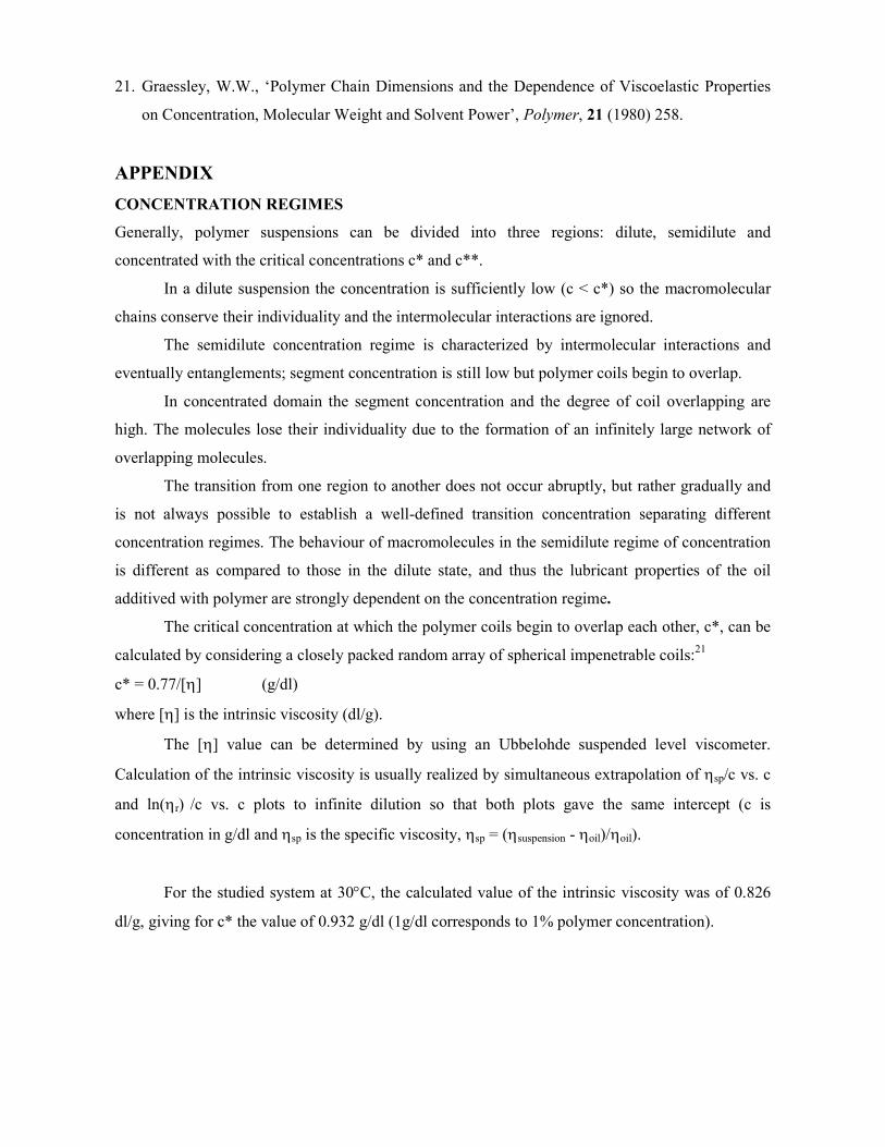
The tests have been carried-out on a modified four-ball machine. The configuration of this
machine is represented in Figure 1. It consists in a four-ball device, an electrical motor, a belt
transmission, and a main shaft supported by two angular contact ball bearings. At the topside of the
main shaft there is a loading spring - screw mechanism, and at the bottom side there is a tapered
hole for the tapered end of a steel chuck, which locks the upper testing steel ball.
Figure 1 Four-ball machine configuration
The four-ball device can well simulate an angular contact ball bearing.16,17 The bottom flat
side of the stationary ball pot represents the bearing outer race, the three lower balls represent the
rolling elements, and the upper ball represents the inner race.
In order to simulate all-steel and hybrid angular contact bearings, the three lower balls were
chosen from steel and silicone nitride, respectively. The test balls are so arranged that their centres
form a pyramid with a nominally equilateral base. Each of the lower balls forms three conjunctions
- one with the top ball and two with the ball pot. The top ball forms also three conjunctions, one
with each of the three lower balls. The upper ball was rotated with a constant speed of 3,000 rpm
(0.864 ms-1 sliding speed). For each test, the four-ball machine ran 60 seconds.
Before and after each tests the four-ball, device elements and the testing balls were cleaned
with acetone and dried in a warm air draught. A constant quantity of 20 millilitres of oil was used
for each experiment, so all the balls were completely covered by lubricant. The bulk temperature of
the oil samples was measured with a thermocouple, mounted at the bottom side of the ball pot. The
oil sample temperature during all tests was maintained at about 30C, no important changes being
observed in oil bulk temperature, due to the short time of testing. After every test, the wear spot
diameters of the lower balls were measured with a laboratory microscope. Each measurement was
repeated six times, a mean value of the wear spot diameter on the lower balls being calculated.
RESULTS AND DISCUSSION
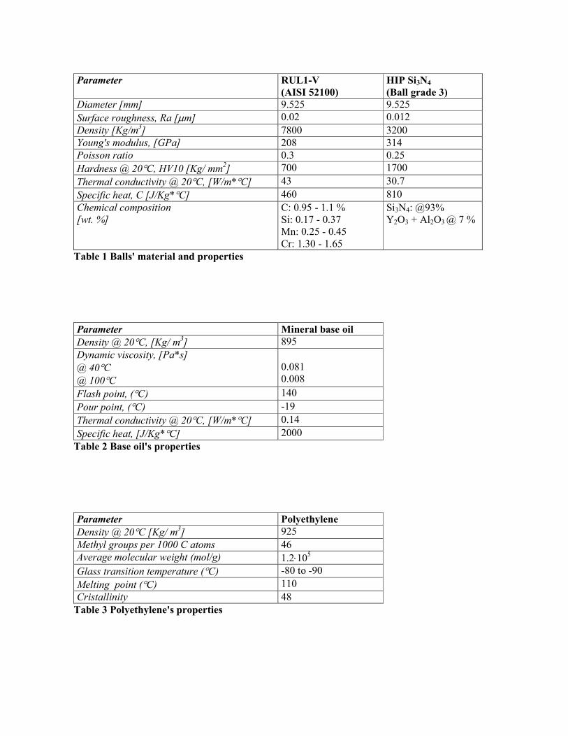
The tests were developed for the base oil (0.0% PE) varying the axial load from 500 N to 1140 N,
for both combinations of balls: upper steel ball on lower steel balls (all-steel pair) and upper steel
ball on silicone nitride balls (hybrid pair). No scuffing was detected for the hybrid pairs, while for
the all-steel pairs the scuffing started at about 750 N axial load (Figure 2).
Figure 2 Wear spot diameter for base oil tests
To investigate the influence of polymer additive on the wear behaviour, the tests on all-steel
couples were made with a constant load of 680 N, while for the hybrid couples were carried out at
1140 N. Figure 3 shows the wear scar diameter as a function of polymer concentration. By
introducing a small quantity of low-density polyethylene, the wear of the steel couples is reduced.
For both types of studied balls, the smallest wear path was found for concentrations between 0.5 –
1.0% PE, whereas for higher values of polymer concentration the wear scar diameter slightly
increases. These results are in agreement with other reported data,7,10-12,19 showing that there is an
optimum value of concentration that belongs to the upper limit of the dilute regime, for which the
maximum of performance can be obtained.
Figure 3 Wear spot diameter for blended oil tests
For an axial load of 680 N, it was very difficult to observe wear spots on silicon nitride balls
lubricated with additived oil samples. To avoid this situation, different values of axial load were
chosen for steel/steel pairs and steel/ceramic pairs. On the other hand, at 1140 N axial force scuffing
occurred on steel/steel balls. In these conditions, no optimum concentration of additive could be
observed for steel/steel pairs.
In the case of mineral oils additived with polymers, the polymer chains are orientated on the
moving directions, acting as a wear protective layer, provided that the polymer quantity to be
completely miscible in the base oil. Some macromolecular coils are trapped to the surface, leading
to a rough layer of polymer, with a thickness corresponding to one coil.11 If the polymer
concentration is too high (in the semidilute and concentrated regime), entangled structures appear,
decreasing lubricant performances.7,12 The chains touch or even penetrate each other due to the lack
of space, and the entanglements formation influences the adsorption of polymer chains on the solid
surface.
The beneficial effect of polyethylene on scuffing resistance is attributed to the formation of
boundary viscous films on the contacting surface that resist to the contact pressure and sliding
speed. At interfaces lubricant/ball specimen, sliding contact and localized heating produce changes
in physical interactions between the lubricant molecules and surface asperities. For the case of steel
ceramic pairs, the surface is smoother as compared with the steel/steel pairs, influencing the wear.
The chemical nature of the ball surface and the polymer concentration influence the
competition between the adsorption phenomena and slip of macromolecules near solid boundaries.
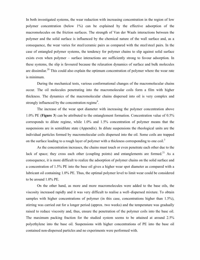
In both investigated systems, the wear reduction with increasing concentration in the region of low
polymer concentration (below 1%) can be explained by the effective adsorption of the
macromolecules on the friction surfaces. The strength of Van der Waals interactions between the
polymer and the solid surface is influenced by the chemical nature of the wall surface and, as a
consequence, the wear varies for steel/ceramic pairs as compared with the steel/steel pairs. In the
case of entangled polymer systems, the tendency for polymer chains to slip against solid surface
exists even when polymer – surface interactions are sufficiently strong to favour adsorption. In
these systems, the slip is favoured because the relaxation dynamics of surface and bulk molecules
are dissimilar.20 This could also explain the optimum concentration of polymer where the wear rate
is minimum.
During the mechanical tests, various conformational changes of the macromolecular chains
occur. The oil molecules penetrating into the macromolecular coils form a film with higher
thickness. The dynamics of the macromolecular chains dispersed into oil is very complex and
strongly influenced by the concentration regime9.
The increase of the wear spot diameter with increasing the polymer concentration above
1.0% PE (Figure 3) can be attributed to the entanglement formation. Concentration value of 0.5%
corresponds to dilute regime, while 1.0% and 1.5% concentration of polymer means that the
suspensions are in semidilute state (Appendix). In dilute suspensions the rheological units are the
individual particles formed by macromolecular coils dispersed into the oil. Some coils are trapped
on the surface leading to a rough layer of polymer with a thickness corresponding to one coil.3
As the concentration increases, the chains must touch or even penetrate each other due to the
lack of space; they cross each other (coupling points) and entanglements are formed.21 As a
consequence, it is more difficult to realize the adsorption of polymer chains on the solid surface and
a concentration of 1.5% PE into the base oil gives a higher wear spot diameter as compared with a
lubricant oil containing 1.0% PE. Thus, the optimal polymer level to limit wear could be considered
to be around 1.0% PE.
On the other hand, as more and more macromolecules were added to the base oils, the
viscosity increased rapidly and it was very difficult to realise a well–dispersed mixture. To obtain
samples with higher concentrations of polymer (in this case, concentrations higher than 1.5%),
stirring was carried out for a longer period (approx. two weeks) and the temperature was gradually
raised to reduce viscosity and, thus, ensure the penetration of the polymer coils into the base oil.
The maximum packing fraction for the studied system seems to be attained at around 2.5%
polyethylene into the base oil. Suspensions with higher concentrations of PE into the base oil
contained non-dispersed particles and no experiments were performed with.
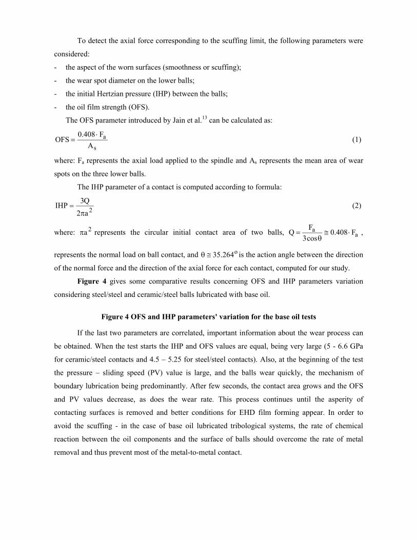
To detect the axial force corresponding to the scuffing limit, the following parameters were
considered:
- the aspect of the worn surfaces (smoothness or scuffing);
- the wear spot diameter on the lower balls;
- the initial Hertzian pressure (IHP) between the balls;
- the oil film strength (OFS).
The OFS parameter introduced by Jain et al.13 can be calculated as:
s
a
A
F408.0OFS
(1)
where: Fa represents the axial load applied to the spindle and As represents the mean area of wear
spots on the three lower balls.
The IHP parameter of a contact is computed according to formula:
2a2
Q3IHP
(2)
where: 2a represents the circular initial contact area of two balls, aa F408.0
cos3
FQ
,
represents the normal load on ball contact, and o264.35 is the action angle between the direction
of the normal force and the direction of the axial force for each contact, computed for our study.
Figure 4 gives some comparative results concerning OFS and IHP parameters variation
considering steel/steel and ceramic/steel balls lubricated with base oil.
Figure 4 OFS and IHP parameters' variation for the base oil tests
If the last two parameters are correlated, important information about the wear process can
be obtained. When the test starts the IHP and OFS values are equal, being very large (5 - 6.6 GPa
for ceramic/steel contacts and 4.5 – 5.25 for steel/steel contacts). Also, at the beginning of the test
the pressure – sliding speed (PV) value is large, and the balls wear quickly, the mechanism of
boundary lubrication being predominantly. After few seconds, the contact area grows and the OFS
and PV values decrease, as does the wear rate. This process continues until the asperity of
contacting surfaces is removed and better conditions for EHD film forming appear. In order to
avoid the scuffing - in the case of base oil lubricated tribological systems, the rate of chemical
reaction between the oil components and the surface of balls should overcome the rate of metal
removal and thus prevent most of the metal-to-metal contact.
CONCLUSIONS
The low-viscosity mineral oil additived with a low concentration of polyethylene (up to 1.0%)
offers good lubrication conditions for both all-steel and hybrid tribological pairs. Furthermore, the
wear of both the all-steel and hybrid pairs decreases, the polymer chains being adsorbed on the
surface and acting as wear protective layers. The antiwear action of polyethylene dissolved in base
oil is governed by the amount of the macromolecules adsorbed on the surface that determines an
optimum value of concentration, near the upper limit of dilute regime.
Scuffing resistance of silicone nitride balls is higher than of the steel balls, when lubricated
with low-viscosity mineral oil. The explanation could not be the better surface quality of the
silicone nitride balls only, but especially the dissimilar properties of the elements in hybrid
tribological systems. Moreover, when using a polyethylene blended mineral oil as lubricant, the
adsorption of polymer chains is facilitated in steel on silicon nitride hybrid pairs.
Silicone nitride balls could successfully replace the steel balls in angular hybrid ball
bearings lubricated with base mineral oils and samples of mineral oil additived with polyethylene.
The improvement of tribological behaviour could be realised either by increasing the
performances of the lubricant (by using polymer additive), or by changing the chemical nature of
the surface (using new materials for the balls).
ACKNOWLEDGMENTS
The authors wish to express their gratitude to the reviewers for making useful comments.
REFERENCES
1. Cann, P.C., and Spikes, H.A., ‘The Behaviour of Polymer Solutions in Concentrated Contacts:
Immobile Surface Layer Formation’, Trib. Trans., 37, 3 (1994) 580.
2. Smeeth, M., Spikes, H.A., and Gunsel, S., ‘The Formation of Viscous Surface Films by
Polymer Solutions: Boundary or Elastohydrodynamic Lubrication?’, Trib. Trans., 39 (3) (1996)
720.
3. Georges, E., Georges J.-M., and Diraison, C., ‘Rheology of Olefinic Copolymer Layers
Adsorbed on Solid Surfaces’, Trib. Trans., 39 (3) (1996) 563.
4. Bartz, W.J., ‘Lubricants and the environment’, New Directions in Tribology, Ed. Hutchings
I.M., Mech. Eng. Pub., (1997) 103.
5. Shoda, Y., Ijuin, S., Aramaki, H., Yui, H., and Toma, K., ‘The Performance of a Hybrid
Ceramic Ball Bearing Under High Speed Conditions with the Under Race Lubrication Method’,
Trib. Trans., 40 (4) (1997) 676.
6. Olaru, D.N., ‘Research regarding the increasing of the rotational speed of radial and angular
contact ball bearings’ (in Romanian), Ph.D. Thesis, Iasi, Romania, (1992).
7. Olaru, D.N., Bercea, I., Bercea, M., and Paleu, V., ‘The Behaviour of Lubricant Oils Blended
with Olefin Polymers’, 11th International Colloquium on Tribology Stuttgart/Ostfildern, January
13-15, (1998), Stuttgart/Ostfildern.
8. Paleu, V., Vergne, Ph., Nélias, D., and Bercea, M., ‘Rheological Behaviour of Mineral Oils
Additived With Polyethylene’, 3rd International Conference of Tribology Balkantrib’99, June 2-
4, (1999), Sinaia.
9. Bercea, M., Bercea, I., Olaru, D.N., and Nélias, D., ‘Polyethylene as an Additive for Mineral
Oils - Part I: Influence of the Polymer Concentration on the Film-Forming Properties in Rolling
Bearing’, Trib. Trans., 42, 4 (1999) 851.
10. Bercea, I., Paleu, V., Bercea, M., and Olaru, D.N., ‘Oil Soluble Polymers and Their
Performances in Rolling/Sliding Contacts’, 10th International Conference VAREHD 10, Oct.
20-21, (2000), Suceava.
11. Bercea, M., Flamand, L., Nélias, D., Paleu, V., Vergne, Ph., and Bercea, I., ‘Comportement
rhéologique et tribologique de lubrifiants avec additif polymère’, Matériaux & Techniques, 3-4
(2001) 21.
12. Bercea, I., Nélias, D., and Bercea, M., ‘Tribological and Rheological Behaviour of Lubricating
Oils Additived With Polymers’, 2nd World Tribology Congress, Sept 03-07, (2001) Vienna.
13. Jain, V.K., Wright, M., and Saba, C.S., ‘Investigation of Ester Based Lubricants Using a Four
Ball Machine’, 43th STLE Annual Meeting in Cleveland, May 9-12, (1988) Ohio.
14. Ku, P.M., Anderson, E.L., and Carper, H.J., ‘Some Considerations In Rolling Fatigue
Evaluation’, ASLE Transactions, 15, 2 (1972) 113.
15. Klaus, E.E., ‘Lubricated Wear of Silicon Nitride’, 45th STLE Annual Meeting in Denver, May
7-10, (1990), Colorado.
16. Hadfield, M., Stolarski, T.A., Cundill, R.T., and Horton, S., ‘Failure modes of pre-cracked
ceramic elements under rolling contact’, Wear, 169 (1993) 69.
17. Wang, Y., and Hadfield, M., ‘Rolling contact fatigue failure modes of lubricated silicon nitride
in relation to ring crack defects’, Wear, 225-229 (1999) 1284.
18. Bercea, M., Paleu, V., and Bercea I., ‘Lubricant Oils Additived with Polymers in EHD
Contacts: Part 1 – Rheological Behaviour’, for publication in Lubr. Sci.
19. Han, D.H., and Masuco, M., ‘Comparison of Antiwear Additive Response Among Several Base
Oils of Different Polarities’, Trib. Trans., 42, 4 (1999) 902.
20. Mhetar, V., and Archer, L.A., ‘Slip in Entangled Polymer Solutions’, Macromolecules, 31
(1998) 6639.
21. Graessley, W.W., ‘Polymer Chain Dimensions and the Dependence of Viscoelastic Properties
on Concentration, Molecular Weight and Solvent Power’, Polymer, 21 (1980) 258.
APPENDIX
CONCENTRATION REGIMES
Generally, polymer suspensions can be divided into three regions: dilute, semidilute and
concentrated with the critical concentrations c* and c**.
In a dilute suspension the concentration is sufficiently low (c < c*) so the macromolecular
chains conserve their individuality and the intermolecular interactions are ignored.
The semidilute concentration regime is characterized by intermolecular interactions and
eventually entanglements; segment concentration is still low but polymer coils begin to overlap.
In concentrated domain the segment concentration and the degree of coil overlapping are
high. The molecules lose their individuality due to the formation of an infinitely large network of
overlapping molecules.
The transition from one region to another does not occur abruptly, but rather gradually and
is not always possible to establish a well-defined transition concentration separating different
concentration regimes. The behaviour of macromolecules in the semidilute regime of concentration
is different as compared to those in the dilute state, and thus the lubricant properties of the oil
additived with polymer are strongly dependent on the concentration regime.
The critical concentration at which the polymer coils begin to overlap each other, c*, can be
calculated by considering a closely packed random array of spherical impenetrable coils:21
c* = 0.77/[] (g/dl)
where [] is the intrinsic viscosity (dl/g).
The [] value can be determined by using an Ubbelohde suspended level viscometer.
Calculation of the intrinsic viscosity is usually realized by simultaneous extrapolation of sp/c vs. c
and ln(r) /c vs. c plots to infinite dilution so that both plots gave the same intercept (c is
concentration in g/dl and sp is the specific viscosity, sp = (suspension - oil)/oil).
For the studied system at 30C, the calculated value of the intrinsic viscosity was of 0.826
dl/g, giving for c* the value of 0.932 g/dl (1g/dl corresponds to 1% polymer concentration).
Parameter RUL1-V (AISI 52100)
HIP Si3N4
(Ball grade 3) Diameter [mm] 9.525 9.525
Surface roughness, Ra [m] 0.02 0.012
Density [Kg/m3] 7800 3200 Young's modulus, [GPa] 208 314 Poisson ratio 0.3 0.25
Hardness @ 20C, HV10 [Kg/ mm2] 700 1700
Thermal conductivity @ 20C, [W/m*C] 43 30.7
Specific heat, C [J/Kg*C] 460 810
Chemical composition [wt. %]
C: 0.95 - 1.1 % Si: 0.17 - 0.37 Mn: 0.25 - 0.45 Cr: 1.30 - 1.65
Si3N4: @93% Y2O3 + Al2O3 @ 7 %
Table 1 Balls' material and properties
Parameter Mineral base oil Density @ 20C, [Kg/ m3] 895
Dynamic viscosity, [Pa*s] @ 40C @ 100C
0.081 0.008
Flash point, (C) 140
Pour point, (C) -19
Thermal conductivity @ 20C, [W/m*C] 0.14
Specific heat, [J/Kg*C] 2000
Table 2 Base oil's properties
Parameter Polyethylene Density @ 20C [Kg/ m3] 925
Methyl groups per 1000 C atoms 46 Average molecular weight (mol/g) 1.2105
Glass transition temperature (C) -80 to -90
Melting point (C) 110
Cristallinity 48 Table 3 Polyethylene's properties
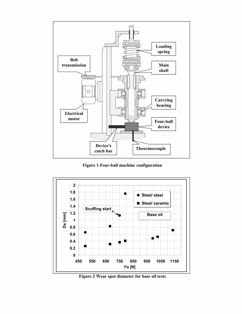
Figure 1 Four-ball machine configuration
Figure 2 Wear spot diameter for base oil tests
0
0.2
0.4
0.6
0.8
1
1.2
1.4
1.6
1.8
2
450 550 650 750 850 950 1050 1150
Fa [N]
Ds
[m
m]
Steel/ steel
Steel/ ceramic
Scuffing start
Base oil
Belttransmission
Electricalmotor
Device'scatch bar
Theormocouple
Four-balldevice
Carryingbearing
Mainshaft
Loadingspring
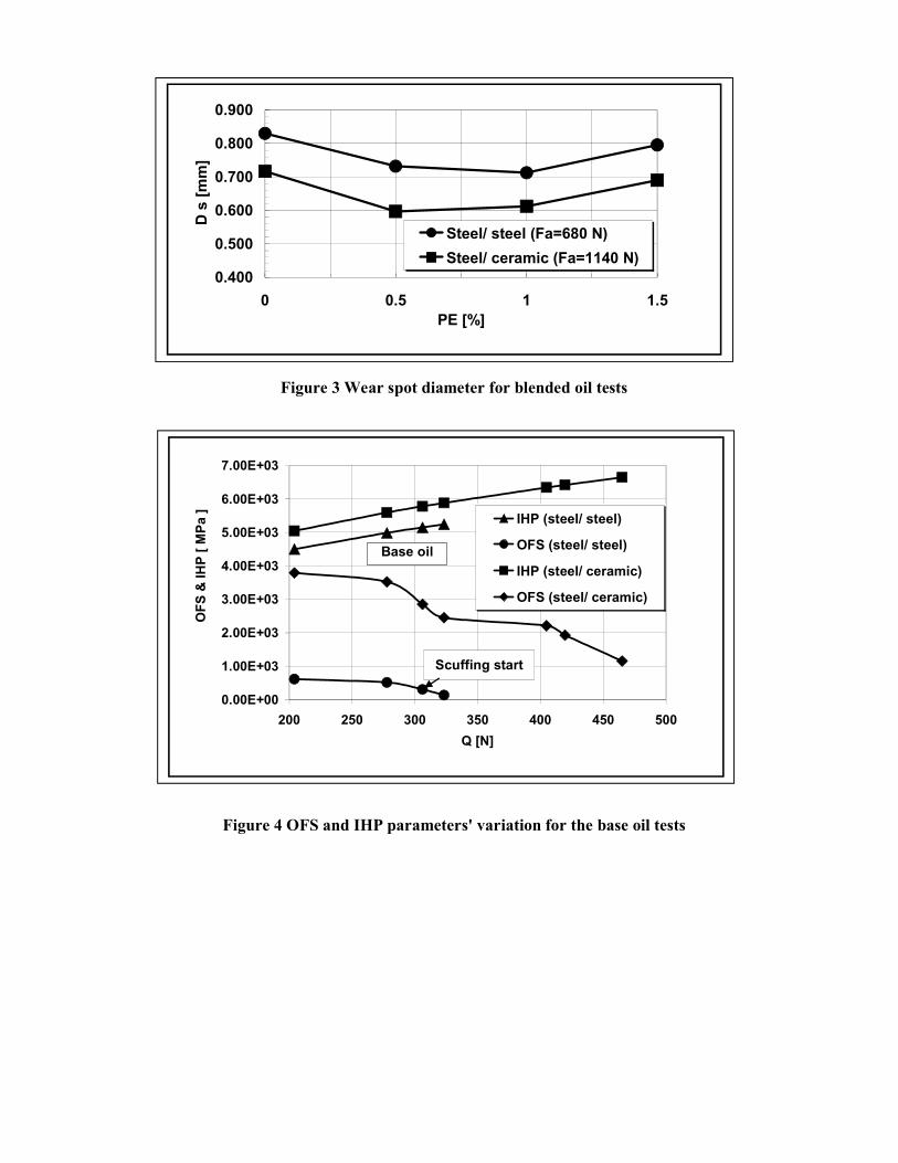
Figure 3 Wear spot diameter for blended oil tests
Figure 4 OFS and IHP parameters' variation for the base oil tests
0.00E+00
1.00E+03
2.00E+03
3.00E+03
4.00E+03
5.00E+03
6.00E+03
7.00E+03
200 250 300 350 400 450 500
Q [N]
OF
S &
IH
P [
MP
a ] IHP (steel/ steel)
OFS (steel/ steel)
IHP (steel/ ceramic)
OFS (steel/ ceramic)
Base oil
Scuffing start
0.400
0.500
0.600
0.700
0.800
0.900
0 0.5 1 1.5
PE [%]
D s
[m
m]
Steel/ steel (Fa=680 N)
Steel/ ceramic (Fa=1140 N)
Related Documents


![Application for FALL or SPRING DUAL CREDENTIAL …[EHD 110D, EHD 170, EHD 160A/B, SPED 175, SPED 160F] until preliminary credentials are granted. Preliminary Multiple Subject and Education](https://static.cupdf.com/doc/110x72/5f797cccca12173bbd21f677/application-for-fall-or-spring-dual-credential-ehd-110d-ehd-170-ehd-160ab-sped.jpg)