1484- 29224 NASA Technical Memorandum 83723 Lubricant Jet Flow Phenomena in Spur and Helical Gears With Modified Center Distances and/or Addendums—for Out-of-Mesh Conditions Lee S. Akin California State University at Long Beach Long Beach, California and Dennis P. Townsend Lewis Research Center Cleveland, Ohio Prepared for the Fourth International Power Transmission and Gearing Conference sponsored by the American Society of Mechanical Engineers Cambridge, Massachusetts, October 10-12, 1984 NASA https://ntrs.nasa.gov/search.jsp?R=19840021155 2018-06-25T09:40:18+00:00Z

Welcome message from author
This document is posted to help you gain knowledge. Please leave a comment to let me know what you think about it! Share it to your friends and learn new things together.
Transcript
1484- 2 9 2 2 4
NASA Technical Memorandum 83723
Lubricant Jet Flow Phenomena in Spurand Helical Gears With Modified CenterDistances and/or Addendums—forOut-of-Mesh Conditions
Lee S. AkinCalifornia State University at Long BeachLong Beach, California
and
Dennis P. TownsendLewis Research CenterCleveland, Ohio
Prepared for theFourth International Power Transmission and Gearing Conferencesponsored by the American Society of Mechanical EngineersCambridge, Massachusetts, October 10-12, 1984
NASA
https://ntrs.nasa.gov/search.jsp?R=19840021155 2018-06-25T09:40:18+00:00Z

LUBRICANT JET FLOW PHENOMENA IN SPUR AND HELICAL
GEARS WITH MODIFIED CENTER DISTANCES AND/OR
ADDENDUMS - FOR OUT-OF-MESH CONDITIONS
Lee S. AkinCalifornia State University at Long Beach
Long Beach, California
Dennis P. TownsendNational Aeronautics and Space Administration
Lewis Research CenterCleveland, Ohio 44135
ABSTRACT
The work reported 1s an extension from a previous study which was limited
to standard centers and tooth proportions only. This paper Includes long and
short addendums and modified center distances. The analysis develops the
equations for the limit values of variables necessary to remove prior severe
0 limitations or constraints necessary to facilitate computer analysis. A newcr>
^ computer program IMPOUT2 has been developed using these newly establishedLU
"Limit Formulas" to prevent negative Impingement on the pinion. The Industrial
standard nozzle orientation usually found where the offset "S = 0" and Inclin-
ation angle "B = 0" will often cause the pinion to be deprived of primary Im-
pingement which can be an Important cause of Incipient scoring failure 1n high-
speed drives.
NOMENCLATURE
•' C C + Aa + a = operating center distance (1n.)L Impingement distance for pinion (see fig. 3) (1n.)L Impingement distance for gear (see fig. 5) (1n.)

N ,N number of teeth 1n pinion and gear respectivelyR standard pitch radius of gear
R = R cos 8 perpendicular distance from gear center (1n.)d X
R base radius of gear (1n.)
R1 (R*r - R*)1/2 offset normal (1n.)R R + Aa operating outside radius of gear (1n.)R = C N / running or operating pitch radius
(N + N ) of gear (1n.)9 P
R R * S radius to gear offset from gear center (1n.)
R = R * S - x gear radius to coincidence of O.D.'s (1n.)x rS offset of Jet stream on gear 0.0. (see figs. 1 and 2)
dlmenslonless offsetS (m1n) minimum theoretical dlmenslonless offset when
= S(m1n)/SQ d (max) = 0 and V. » simultaneously (seefigs. 11 and 12)
S_ offset of Jet to crotch (or coincidence) of 0.0. 's (see
fig. D dn.)S offset of Jet stream on pinion 0.0. (see fig. 4) (1n.)V oil Jet velocity from nozzle exit (1n./sec)V. m1n Jet velocity when d = 0 for given u (1n./sec)J P P
a = R - R operating gear addendum (1n.)a = r - r operating pinion addendum (1n.)d depth of Impingement on gear (1n.)
d depth of Impingement on pinion (1n.)d (max) maximum theoretical depth on pinion V «P 9
1nv<t> = Involute function of <t> (typical) (rad.)tan 4> - <t>og ^ogm gear reduction ratioP normal diametral pitchr standard pitch radius of pinion
r = r cos B perpendicular distance for pinion center (1n.)a Xr = r cos <j>, base radius of pinion (In.)
r = rn * AaD operating outside radius of pinion (1n.)r = C N / running or operating pitch radius of pinion (1n.)
(NP * V

r$ = rr - S offset radius from pinion center (1n.)r = r - S * x pinion radius to coincidence of O.D.'s (1n.)
t generalized time of Jet flight and gear rotation (sec)
tf total time of flight to Jet Impingement (sec)t total time of rotation (sec)x arbitrary offset distance from S (see fig. 2) (1n.)
B arbitrary Inclination angle of Jet stream (rad.)
* B, = (B - B )/ normalized positive Inclination angle(B max - B )
* B. = (B - B )/ normalized negative Inclination angle(B - B m1n)P
B maximum Inclination angle permittedmax0 minimum Inclination angle permittedB Inclination angle when Jet passes through pitch point
(rad.)B Inclination angle when Jet passes through crotch of
0.0. 's and pitch point (S = SQ) (rad.)a = d P 12 dimenslonless Impingement depth, pinion or gearnAa = AN / gear addendum modification (1n.)
(2Pn cos <|»)Aa pinion addendum modification (1n.)
= AN /(2P cos ijOp n *'AN tooth addendum modification for Aa9 9
AN tooth addendum modification for AaP P
AP differential Jet pressure at nozzle exit (psl)o» angular velocity of pinion (rad/sec)* normal pressure angle (rad.)* pressure angle at O.D. of gear (rad.)* _ pressure angle at lowest Impingement point on pinion
(rad.)essure
tangential standard pressure angle (rad.)<l> pressure angle at o.D. of pinion (rad.)
«t>tr tangential operating pressure angle (rad.)<|r helix angle (deg.)6 , Initial position of gear tooth at beginning of pinion
Impingement cycle (t = 0) (rad.)

6 _ Initial position of gear tooth at beginning of gearImpingement cycle (rad.)
6 _ final position of gear at max. Impingement depth(tf = tj (rad.)
e Initial angular position of pinion tooth at beginning ofpinion Impingement cycle (t = 0) (rad.)
e ? final position of pinion tooth at maximum Impingementdepth (ts = tw) (rad.)
e final position of pinion tooth when Just missed by jetpostream (t = 0) (rad.)
e Initial position of pinion tooth at beginning of gearImpingement cycle (t = 0) (rad.)
INTRODUCTION
In the gearing Industry, gears are lubricated and cooled by various met-hods. At low to moderate speeds and loads, gears may be partly submerged 1nthe lubricant which provides lubrication and cooling by splash lubrication(ref. 1). with splash lubrication, power loss Increases considerably withspeed as shown 1n Ref. 1. This 1s partially because of churning losses. InRef. 2 1t 1s shown that gear scoring and surface pitting can occur when thegear teeth are not adequately lubricated and cooled. The results of Ref. 3for spur gear oil Jet lubrication show that as the gear pitch line velocityIncreases at a constant 1nto-mesh lubrication condition, the limiting toothload that will cause gear scoring 1s drastically reduced. This 1s primarilybecause the method of lubrication does not provide adequate cooling at the
Increased pitch line velocity. In a study of high speed heavy duty gears(ref. 4) the authors showed that the oil Jet location and amount of oil flow
to the gears varies nearly linearly with gear pitch line velocity and alsowith tooth load. In Ref. 5 the authors showed that with radial Jet lubricationthe gear tooth temperature at various speed and loads can be considerably re-
duced by Increasing the lubricant jet pressure and flow rate to obtain better
cooling, it was shown 1n Refs. 5 and 6 that the oil jet lubrication 1s themost effective method when the Jet 1s directed 1n the radial direction with
adequate pressure and flow. Many gears are lubricated by directing the oilJet at the engaging side of the mesh (Into mesh lubrication) or at the disen-gaging sides of the gear mesh (out of mesh lubrication). In Refs. 7 and 8,the authors analyzed oil Jet lubrication when the oil jet 1s directed at the

engaging side of the gear mesh. In Refs. 7 and 8 1t was shown that there 1s
an optimum oil Jet velocity and oil Jet location to obtain the best lubrication
and cooling for 1nto-mesh lubrication.
In Ref. 9 the oil Jet lubrication for out of mesh lubrication was analyzed
and the oil Jet Impingement depth was determined for standard gearing dimen-
sions. Also 1n Ref. 9 the oil Jet location an direction were limited to a no
offset condition (directed at the pitch point only) and 1n a direction normal
to the line of center. This method will give good results for standard gear
dimensions with gear ratios close to unity. However, when nonstandard dimen-
sion, spread center distance, etc. and large gear ration are used the oil Jet
direction and location should be changed to provide the optimum oil Jet Im-pingement depth and maximum cooling condition.
The objective of the work reported herein 1s to analyze the out of meshJet lubrication with most of the simplifying constraints used 1n reference 9
removed. Since most high performance gears require addendum modifications and
1n addition sometimes spread centers, the analysis presented herein set out to
Include these and other related conditions. One practical constraint 1s added:
a nozzle orientation that allows a pinion or gear to be missed provides no
primary cooling to the missed member. Such solutions are not permitted 1n
this analysis since they are not of practical value and can mislead an Inex-
perienced gear design engineer.
BRIEF DESCRIPTION OF THE IMPINGEMENT CYCLE
The beginning of the pinion Impingement cycle 1s about to start as theleading edge of the top land of the gear 1s passed as shown 1n F1g. 1. Gear
tooth rotation continues toward the Jet stream until the Jet reaches the
trailing edge of the gear tooth as shown 1n F1g. 2. At this position the time
t 1s set at zero (t = 0) and the geometrical position of the gear e , 1scalculated. Also the Initial position of the pinion e . 1s calculated
at (t =0). Then the geometry of the lowest Impingement point on the pinion
1s established by setting the time of flight of the jet stream head equal to
the time of rotation on the pinion from (t = 0) until Impingement on the pinion
takes place at e _ as shown 1n F1g. 3, (@tf = t ). Figure 4 shows
the Initial position of the Jet head (@t = 0) when the Impingement flow toward
the lowest Impingement point on the gear 1s Initiated. Here the Initial posi-
tion of the pinion 1s e and e for the gear. Again the times of

flight and rotation are equated (t, = t ). Impingement at the lowest pointon the gear ( L ) 1s shown 1n fig. 5. The gear position 1s e at
this lowest point of Impingement.'
Thus the depth of primary Impingement on the gear 1s d as shown 1n
the figure. When the Jet velocity V 1s reduced below V, (m1n) they j
pinion 1s missed and the Impingement depth on the gear 1s not Increased as
expected but reduced. nMODEL CONTROLS AND RESTRAINTS
Development of the mathematical model used 1n Ref. 1 was restricted to
spur gears and the nozzle position was restricted to the arbitrary offset dis-
tance S = 0 and arbitrary Inclination angle 0=0 orientation. The geomet-
ric definition of S and 8 are described below and shown 1n F1g. 1. The
above restrictions have been removed 1n this mathematical development. Also
the origin for the jet stream trajectory 1s defined as the position where the
Jet crosses the gear outside diameter (0.0.) as shown 1n F1g. 1 at A. B, and
C. Position A shows the general case where 0 < S < S_ and B 1s a specialcase where S = Sn and C 1s the classic case where S = 0 pointing at the
pitch point and perpendicular to the line of centers.
In this paper the value of the arbitrary offset S where the jet line
crosses the gear I.D. 1s restricted to S(m1n) < S < SQ where
, (aqr
mq - V> + V - aPr
0 = mg * 1 2rr(mg + 1)
as shown In F1g. 1 (see Nomenclature for variable definitions not described 1n
text). Thus the operating (or running) offset SQ to the crotch or common
Intersection of the outside diameters 1s the maximum value allowed for the
offset S to remain within the geometric definitions described 1n this paper.
Further when the addendum modification Aa and Aa are unequal andpr gr
extreme enough to cause S_ to be negative then Sfl < S < 0. Also when
Aa = Aa = Aa = 0 with standard centers, S_ reduces toP 9 0
S (Std) = (1/(P cos *))((N /N ) - 1)/((N /N ) + 1) = a(m - l)/(m + 1)!J r it r *J «*

Also the Inclination angle B 1s confined to point at the line of centers
between the confines of the outside diameters of the pinion and gear respect-
ively as shown 1n F1g. 1.
The Inclination angle B 1s considered positive when slanted from right
to left through the point of origin A, B, or C as shown 1n F1g. 1. At B = 0
the jet 1s pointed perpendicular to the line of centers, and when 0 1s nega-
tive 1t 1s slanted from left to right through the point of origin on the O.D.
of the gear, not shown 1n F1g. 1. It 1s not usually considered wise to use
negative B angles with near standard proportion gears lest we starve the
gear of adequate coolant.
The mathematical definition of the arbitrary Inclination angle B 1s:
B = tan~ (x/R.) (2)
where:
R1 = <R02r-R!r'-and
x = an arbitrary offset distance from "S" position to where the Jet
stream crosses the common line of centers.
R = R + Aa = Operating outside radius
RQ = N /(2Pncosn;) + l/Pn = Std. O.D., gear
R = R + s = Radius to offset from gear center
R = C N /(N * N ) = Operating pitch radius, gear
Aa = AN /(2P cos »|») = gear addendum modification
When B 1s given then,
x = R. tan B, where B 1s arbitrary
Thus to remain within the confines established for B, B , and B ,max minare defined as:
Smax - tan-1[(S*apr)/R1]

Also, for any given offset "S" the angle 0 to the pitch point 1s (used as
a normal 1 zer) ;
0 = tan~l(S/R1) (3)
and further 1f S = SQ then the angle to the pitch point 1s
since 0 can be arbitrarily selected, 1t 1s necessary to provide the user
with a normalized (dlmenslonless) Input value for 0 that won't be out of
bounds of the solvable geometry. This 1s done here using the 0. Input pa-
rameter where -1 < 0. < 1 and 1s defined as; when 0. 1s positive (+):~~ ~
- V *and when 0^ 1s negative (-):
so that when;
01 = 0 : 0 = 0p (pointing at pitch point)
0 ^ = 1 : 0 = 0max (pointing at O.D. pin.)
0^ = -1 : 0 = 0mln (pointing at O.D. gr.)
Further 1f the user desires to know the value of 0^ that will make 0=0,
he calculates 0 from:
0UIQ = r — ~B ^ 0* 1s negative as 1s usual
Similarly, when S 1s normalized we get:
S1 = S/SQ (6)
where the value of S. 1s confined to S., . . < S. < 1.1 l(min) ~ 1 ~
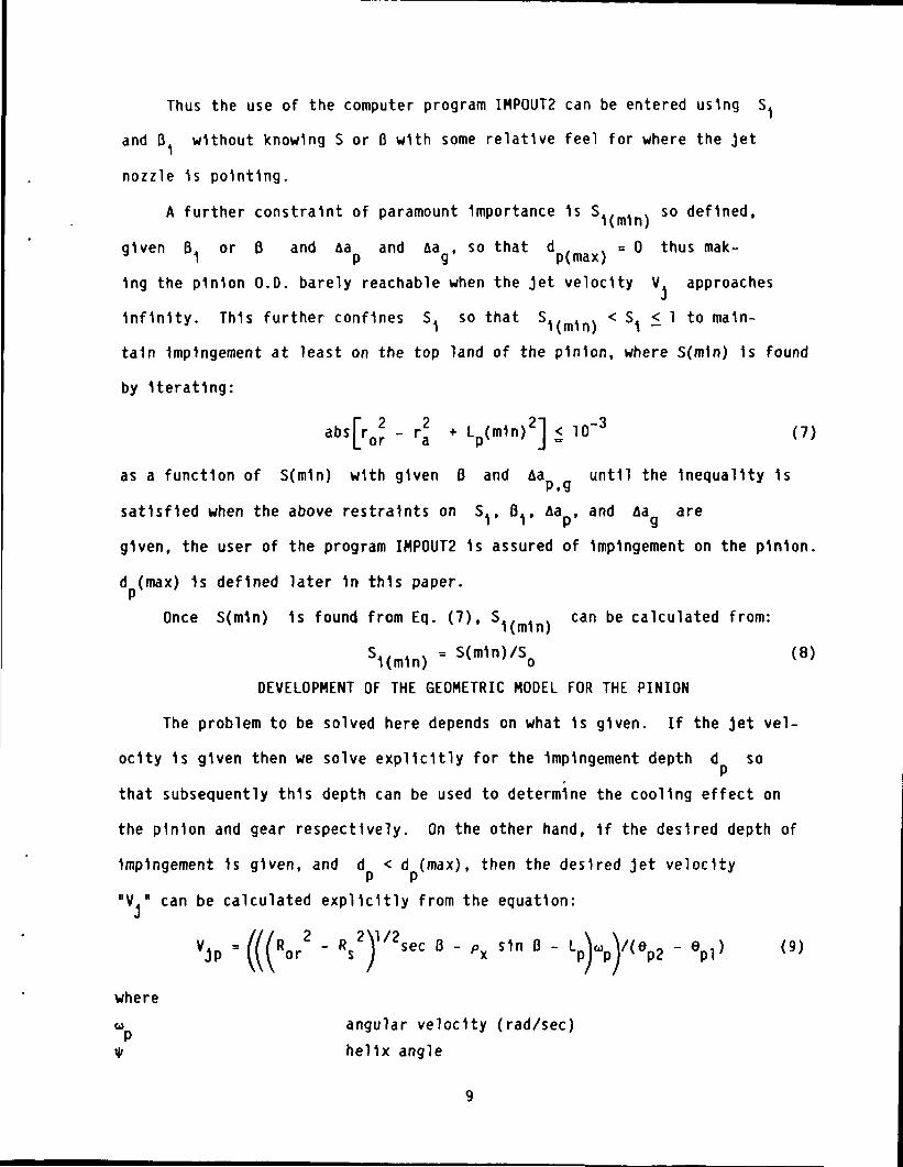
Thus the use of the computer program IMPOUT2 can be entered using S,
and B. without knowing S or 0 with some relative feel for where the jet
nozzle 1s pointing.
A further constraint of paramount Importance 1s S.. . . so defined,
given B. or B and Aa and Aa , so that d . . = 0 thus mak-1 P 9 p(max)1ng the pinion 0.0. barely reachable when the Jet velocity V. approaches
Infinity. This further confines S. so that S^. ^ . < S. < 1 to main-
tain Impingement at least on the top land of the pinion, where S(m1n) 1s found
by Iterating:
[rabsror - ra *
as a function of S(m1n) with given B and Aa until the Inequality 1s
satisfied when the above restraints on S. , B., Aa , and Aa are
given, the user of the program IMPOUT2 1s assured of Impingement on the pinion
d (max) 1s defined later 1n this paper.
Once S(m1n) 1s found from Eq. (7), S.. . . can be calculated from:
S1(m1n) ' S(m1n)/So <8>DEVELOPMENT OF THE GEOMETRIC MODEL FOR THE PINION
The problem to be solved here depends on what 1s given. If the jet vel-
ocity 1s given then we solve explicitly for the Impingement depth d so
that subsequently this depth can be used to determine the cooling effect on
the pinion and gear respectively. On the other hand, 1f the desired depth of
Impingement 1s given, and d < d (max), then the desired let velocityP P
"V." can be calculated explicitly from the equation:J
VJP = Ror2 - R s 2 / 2 s e c 0 - PX sm B - L/^ - epl) (9)
where
w angular velocity (rad/sec)\l» helix angle

N number teeth on pinionN number of teeth on gear wheel9
Aa = AN / pinion addendum modificationP P(2Pncos«|,)
r = r - S + x radius to Jet stream Intersection on line of centersfrom pinion center (see fig. 2)
r = C N / pinion operating pitch radius (1n.)(N + N )9 P
C = C * Aa * Aa operating center distance (In.)
L = ((>"or-dn) Impingement distance (1n.), (see fig. 3)_ r
2)d
r = r + Aa operating outside radius of pinion (1n.)r = N /(2P cosi|») outside radius of pinion (see fig. 1)+ 1/Pn
r = r cos 3 perpendicular distance from pinion center (seea xMg. 2)
d Impingement depth from pinion O.D. (1n.) (see fig. 3)e = m e jet head position t = 0 (see fig. 2)
* 1nv <|>- 6
m = N /N gear ratio (see fig. 2)«j>. = cos" operating pressure angle (see fig. 5)
N. = N + N1 P gAa. = Aa + Aa
1 !? g4>. = tan transverse pressure angle
-1(tan<t>n/cos»iO = cos (Ru/R)4> normal pressure angle at pitch radius1nv<t> = tan<|> radians (see fig. 4)
.egl = cos (R
s/Ror) " 1nv<t>og * 1nv*tr (see
* = cos~ pressure angle at gear 0.0.
1nv<t> = tan<j> .. . ... _.og vog radians (see fig. 2)- *
09 1e ~ = tan radians(Lp/ra) +
10
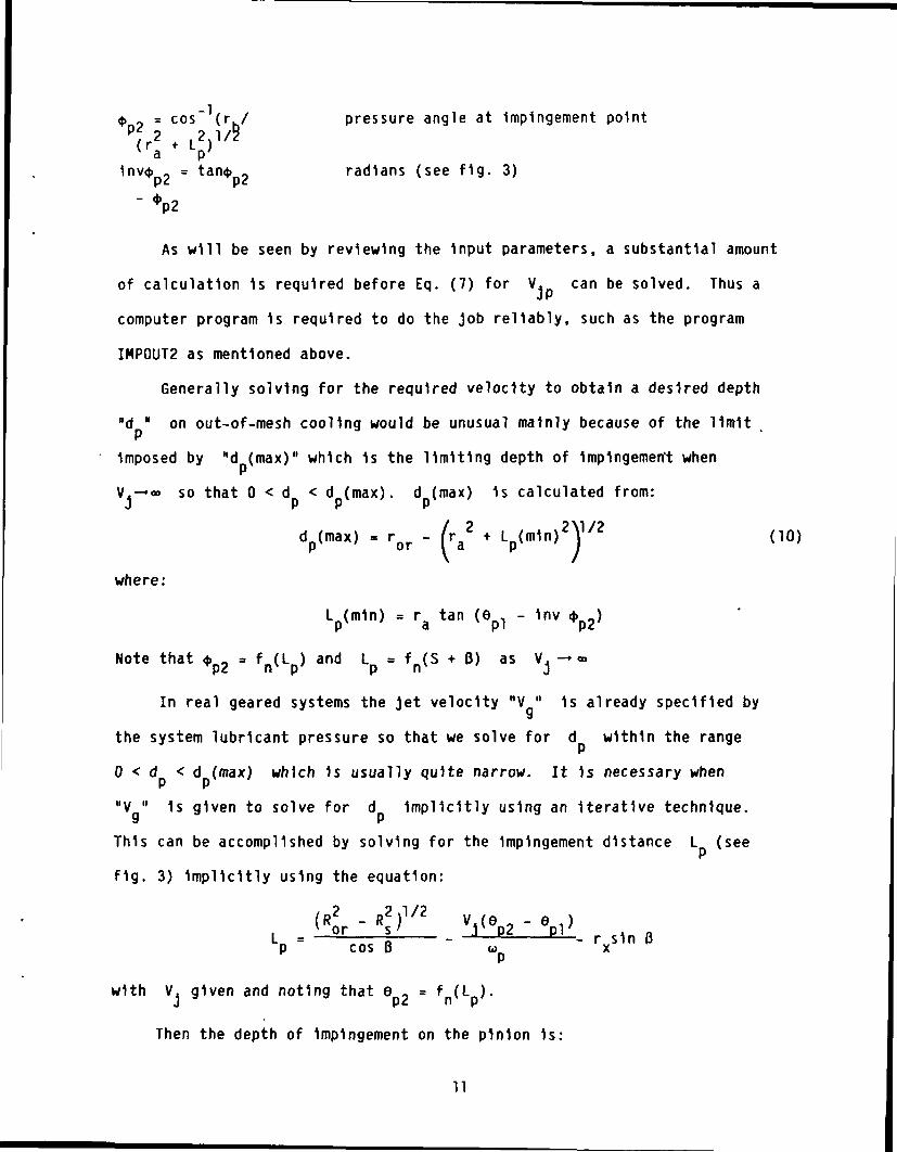
4> 9 = cos" (r./ pressure angle at Impingement pointp 2 2 1/z<ra * V
1nv<t> = tan$ _ radians (see fig. 3)
-vAs will be seen by reviewing the Input parameters, a substantial amount
of calculation 1s required before Eq. (7) for V, can be solved. Thus a
computer program 1s required to do the Job reliably, such as the program
IMPOUT2 as mentioned above.
Generally solving for the required velocity to obtain a desired depth
"d " on out-of-mesh cooling would be unusual mainly because of the limit
Imposed by "d (max)" which 1s the limiting depth of Impingement when
V.-»c9 so that 0 < d < d (max), d (max) 1s calculated from:J r r r
- ror
where:
L (mln) = ra tan (epl - 1nv 4>p2>
Note that * _ = fn(L ) and L = fR(S + B) as V. -»«
In real geared systems the jet velocity "V " 1s already specified by
the system lubricant pressure so that we solve for d within the range
0 < d < d (max) which 1s usually quite narrow. It 1s necessary when
"V " 1s given to solve for d Implicitly using an Iterative technique.
This can be accomplished by solving for the Impingement distance L (see
fig. 3) Implicitly using the equation:
. r .LP = E TB— - — - rxs1n
with V, given and noting that e 2 = f (L ).
Then the depth of Impingement on the pinion 1s:
11
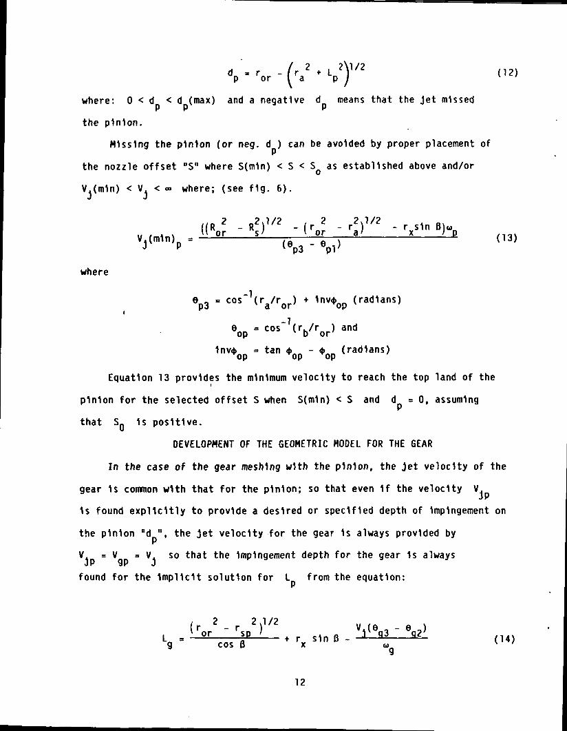
where: 0 < d < d (max) and a negative d means that the Jet missed
the pinion.
Missing the pinion (or neg. d ) can be avoided by proper placement of
the nozzle offset "S" where S(m1n) < S < S as established above and/or
V.(m1n) < V. < - where; (see fig. 6).
' ' U I J__ V <* A _/ V t •» « »
where
_1e 0 = cos (r /r ) + Inv* „ (radians)p3 a or op
°op = cos"1(rb/ror) and
1nv<j> = tan <» - <t> (radians)op op op
Equation 13 provides the minimum velocity to reach the top land of the
pinion for the selected offset S when S(m1n) < S and d = 0, assuming
that SQ 1s positive.
DEVELOPMENT OF THE GEOMETRIC MODEL FOR THE GEAR
In the case of the gear meshing with the pinion, the Jet velocity of the
gear 1s common with that for the pinion; so that even 1f the velocity V.
1s found explicitly to provide a desired or specified depth of Impingement on
the pinion "d ", the Jet velocity for the gear 1s always provided by
V = V = V. so that the Impingement depth for the gear 1s alwaysJ r ilr J
found for the Implicit solution for L from the equation:
12

where we note that
e _ = f (L ) (see fig. 5)g3 nv p'
r = r - S = offset radius from pinion center (See fig. 4)sp r p
S = ((r r2 - rx
2 cos2B|1/2 + rxcos Bj sin B - (x - S) (see fig. 4)
R = R + S - xx r
6 _ = 6 ./m + 1nv <(>. + B (see fig. 4)g2 p4 g ^tr
eg3 = tan'Lg^) + 1nv <t>g3 (see fig. 5)
ep4 = cos"1(rsp/ror) ' 1nv or * 1nv *tr) (see f1g' 4)
R = R cos 0 (see fig. 5)
1nv <t> = tan $ - <t> (radians)
R = R cos <(>. (see figs. 3 and 5)
Then the Impingement depth on the gear 1s calculated from:
( 2 2\l/2Ra * Lg )
COMPUTERIZED PARAMETRIC STUDY
A rather Intricate computer program has been developed which should be
useful to the design engineer as well as the researcher performing parametric
studies. This program "IMPOUT 2" was used 1n the study for this section of
the paper.
13

The out-of-mesh nozzle orientation Imposes severe Impingement depth prob-
lems especially when the gear ratio 1s larger than one-to-one. This 1s demon-
strated 1n F1g. 7 where 1t can be seen that when the gear ratio "m " 1s
equal to one (1.0) the depth of jet oil Impingement 1s equal on pinion and
gear for a perpendicular jet pointed at the pitch point. However, when m
1s larger than unity, the Impingement depth on the pinion 1s very dependent on
the offset "S". This 1s shown 1n F1g. 7 using the dlmenslonless offset S..
As can be seen when S. = 1.0, the position at the Intersection of the pinion
and gear 0.0.'s the jet 1s pointed at the pitch point B, = 0. Both pinion
and gear have near equal Impingement depth. But as the offset S^ 1s lowered
or the gear ratio 1s Increased, the Impingement on the pinion rapidly disap-
pears. In the figures at S. = 0.96, the depth disappears at m = 6.0
and at S. = 0.863 1t disappears at 2.5, and at S. = 0 1t disappears at
1.2. Obviously, when S. = 0, the pinion receives jet Impingement only
when m 1.2. This Illustrates the Idea that for a given p1n1on/gear tooth
combination we need to know S.(m1n) where no Impingement 1s possible even
when the jet velocity V. approaches Infinity (V. — «). This then
allows solutions for d and V. when S.(m1n) < S < 1.0. The gear
depths d area also shown for tooth with a working depth of 0.25 1n. and
therefore primary Impingement can only reach about l/10th the working depth as
shown. Figure 8 shows the effect of the Inclination angle B, on pinion
Impingement depth d . As expected when the jet pressure 1s Increased so 1s
the Impingement depth and as the B. ratio 1s decreased the depth 1s In-
creased up to the maximum depth d (max) as a function of S. and B,
per Eq. (10).
Figure 9 shows the effect of offset S. on Impingement depth d
and d on a mesh with long and short addendums and a spread center distance
14
to accommodate a large gear ratio on a fixed or given center distance. The
mesh has been somewhat overcompensated so that S_ 1s negative which 1s
rare and reverses the situation such that the gear now 1s the member that can
be easily starved 1f the Jet nozzle 1s not placed properly. Here, as can be
seen, the depth d Improves as S, 1s Increased above S = 0.6667
and when optimized by one of the three methods available 1n IHPOUT2 will still
provide an equal Impingement depth for both the pinion and gear at dimension-
less depth of about 6 s 0.1, where « = d/whole depth. Also usually the pro-
gram option 3 has a large value than option 2 which 1s also reversed relative
to standard mesh conditions.
Figure 10 shows the results of setting S. = 0 and B. = 0 and ad-
Justing the pinion and gear addendums to realize the balance of depths of Im-
pingement desired. Here as 1s seen 1n F1g. 10, as Aa 1s reduced AC 1s
reduced and at Aa = 0.0662 an equal (or optimum) Impingement depth 1s
reached on the pinion and gear. The connected circles at A depict the depths
when Aa = 0.10 and Aa = -0.0375. Obviously we must optimize usingr «J
S. and 8, as discussed 1n F1g. 9. The connected circles at C depicts
the depths when Aa = 0.08375 for the pinion and -0.0375 for the gear
are closer together than 1n "A". Further, when Aa Is further reduced to
Aa = 0.06875 as In "B" the depths get much closer together and at Aa =P P
0.0662 = -Aa when optimized on Aa the depths are equal.9
Figure 11 shows the effect of B, on S.(m1n). The 21/35 tooth com-
bination was used as the example here. This figure shows that 1f B 1s
slanted backwards 1n the negative direction, that S. can be made smaller
before the pinion 1s starved. Also 1f the offset S. 1s set at 1.0 1t 1s
nearly Impossible to starve the pinion at any reasonable Inclination angle 0,
or B, ratio, even when the pressure 1s modest.
15

The last F1g. 12 shows the effect of the dimenslonless offset S, on
the minimum velocity or Us cause, jet nozzle pressure at the nozzle exit
(V (m1n) = velocity needed to reach pinion O.D.). As 1s seen 1n the figure,J
S.(m1n) establishes the asymptote where V.(m1n) approaches Infinity.
TH1s makes 1t clear that we cannot set S. below S.(m1n) and expect to
obtain primary Impingement on the pinion top land or profile at any jet
pressure.
DISCUSSION
Figures 11 and 12 show the most Important results of this study, 1n that
they point out the Importance of careful placement of the nozzle 1n both posi-
tion and pointing direction, especially at higher gear ratios considered 1n
F1g. 7. Also for out-of-mesh nozzle orientation, Increasing the oil Jet pres-
sure and velocity to high levels may not always Improve the primary Impingement
depth appreciably as shown 1n F1gs. 9, 10, and 12, and 1n practical fact may
sometimes cause flooding 1n the gear case or housing. Further, 1f the Inclin-
ation angle B 1s adjusted to an extreme, per F1g. 8, to Improve the Impinge-
ment depth on the pinion, then the gear depth 1s diminished usually
unacceptably.
Even when the position 1s fixed 1n the historically standard orientation
position which will not allow primary Impingement on the pinion for even modest
gear ratios (at any jet pressure), the pinion and gear addendums can be ad-
justed per F1g. 10 to provide adequate Impingement on both mesh members. This
has been done 1n the past to control Incipient scuffing or scoring, often
without the designer realizing he was also controlling the Impingement and
cooling phenomena favorably.
16

SUMMARY OF RESULTS
An analysis was developed for the lubricant Jet flow In the out of mesh
condition. THe analysis provides for the Inclusion of modified center dis-
tances and modified addendums. The equations are developed for the limit val-
ues of variables necessary to remove the severe limitations or constraints
necessary to facilitate computer analysis. A computer program was developed
using these "Limit Formulas" to prevent negative Impingement (missing) on the
pinion. THe following results were obtained:
1. The Industrial standard nozzle orientation usually found where the
offset S = 0 and Inclination angle B = 0 will often cause the pinion to be
deprived of primary Impingement which can be an Important cause of Incipient
gearing failure 1n high-speed drives.
2. For ratios larger than 1:1, the oil jet will only Impinge on the
gear teeth unless a minimum calculated jet velocity 1s provided to lubricate
the pinion teeth.
3. When a minimum on Jet velocity Is provided, the oil Jet offset must
be equal to or greater than a minimum calculated offset to assure Impingement
on the pinion.
4. As the oil Jet velocity 1s Increased above the calculated minimum
value, the Impingement depth will Increase but at a decreasing rate. The max-
imum Impingement depth will generally not exceed 10 percent of the tooth pro-
file depth.
17

REFERENCES
1. Umezawa, K., Inoh, T. and Katah, H., "Power Loss of Automobile
Transmission with Exact Measurement of Total Heat Rejection," The
International Symposium on Gearing and Power Transmissions. JSME, Tokyo,
Japan, Aug. 30 to Sept. 3, 1981, pp. 287-292.
2. Dudley, D. W., "Characteristics of Regimes of Gear Lubrication," The
International Symposium on Gearing and Power Transmissions. JSME, Tokyo,
Japan, Aug. 30 to Sept. 3, 1981, pp. 319-324.
3. Naruse. C., Halzuka, S., and Nemoto, R., "Studies on the Limitation Load
for Scoring of Gears," The International Symposium on Gearing and Power
Transmissions. JSME, Tokyo, Japan, Aug. 30 to Sept. 3, 1981, pp. 371-376.
4. Oo1, Y., et al., "On Bulk Temperature 1n High Speed and Heavy Duty Gears,*
The International Symposium on_ Gearing and Power Transmissions. JSME,
Tokyo, Japan, Aug. 30 to Sept. 3, 1983, pp. 247-252.
5. Akin, L., Mross, J. J., and Townsend, D. P., "Study of Lubricant Jet Flow
Phenomena 1n Spur Gears," Journal of. Lubrication Technology. Vol. 97,
Ser. F, No. 2, Apr. 1975, pp. 283-288.
6. Townsend, D., and Akin, L., "Analytical and Experimental Spur Gear Tooth
Temperature as Affected by Operating Variables," 1980, Journal of
Mechanical Design. Vol. 103, No. 4., Jan. 1981, pp. 219-226.
7. Akin, L. S., and Townsend, D. P., "Into Mesh Lubrication of Spur Gears
with Arbitrary Offset, Part I - For 011 Jet Velocity Less Than or Equal
To Gear Velocity," Journal of Mechanisms. Transmissions and Automation 1n
Design. Vol. 105, No. 4., Dec. 1983, pp. 713-718.
18

8. Akin. L. S.t and Townsend, D. P., "Into Mesh Lubrication of Spur Gears
with Arbitrary Offset, Part II - For 011 Jet Velocity Equal To or Greater
Than Gear Velocity," Journal of. Mechanisms. Transmissions and Automation
1n Design. Vol. 105, No. 4., Dec. 1983, pp. 719-724.
9. Townsend, D., and Ak1nf L.f "Study of Lubricant Jet Flow Phenomena 1n
Spur Gears - Out of Mesh Condition," Journal p_f_ Mechanical Design.
Vol. 100, No. 1., Jan. 1978, pp. 61-68.
19

>- (3IS VARIABLE +ORIENTATION
(SHOWN IN +ORIENTATION)
Figure 1. - Jet coordinate origins for impingement on pinion. A = generalcase where 0< S < S0; B = special case where S = S0; C = classic casewhere S = 0°.
cos'1 <Rs/Ror> 9
JET STREAM (@t =0)
Figure 2. - Impingement on pinion (§t = 0).

Figure 3. - Impingement on pinion (@t f = tu).
'op
Figure 4. - Impingement on gear (@t = 0).

Figure 5. - Impingement on gear (@t f = tu).
NEC. dp (MISSED PINION)
(min)
Figure 6. - Missing the pinion when V: < V: (min).

1 d S j = 02 dj, S j= .8633 d S - . 9 64 d , S j - L O5 dj-dfl, opt 5, Sj6
JD
7 dj, S j = . 9 68 dj, S.- .8639 d , S j = 0
r .98
3 84 5 6 7GEAR RATIO, mg
Figure 7. - Effect of gear ratio on impingement depth, (3: = 0,AP = 138 psi, n = 5000 rpm, Np = 28.
10
c
OL
.05
.04
.03
.02
.01
0 100 250 500 1000 1500 2000
JET VELOCITY, Vj( in /sec
Figure 8. - Effect of fy on impingement depth, Sj = 1.0,21/35 combination.

1 d S =02 dp, S j= .33333 dp, Sj =.66674 tfp-dg.lij-0, S -S(opt). opt'n?
8 dq, S- .33339 d . S = 0
= 0, S =S(opt), opt'n5
t ' n 3
Aaq = -.0375. Ac = .0625aq = -. 0375, Ac =. 0.,=-.0375= .0662, OPTIMIZED
1 dp , Aap = ., , ^-.wt,2 dp, Aap =. 084375,y AaQ - -. 0375, Ac =. 0468753 d AaJ=.06875, Aan
y=-.03754 dp = % Aap = -Aaq • -0662, O5 d Aa =.084375, Aag = -.03756 d Aap =. 06875, Aaq = -. 0375, Ac =. 031257 dg, Aap=.10, Aag=-.0375
.10
.09
.08
.07
.06C nc•- .05en .04
^ .03
02
.01
1 — •
— 2i
3n
k^— 4-^ 5"i 6~\-^ • i
^-^__ __, jj— ^
^H2-! r-l — l — i r — f200 300 400
JET PRESSURE, psi500 600 700
Figure 9. - Effect of offset Sj on impingement depth. 12/43comb. , Pj = 0, Aaq = -. 0375. Ac = . 0625, Aap = . 1, DP =8, <p = 20°.
. AU
.09
.08
.07c n^.= • UO
en -05
•^ .04
.03
.02
.01
i
^_
C
f!1 1 *
- R j l 1
^"— Vg = PLV(@n =5000rpm
•^^_ ^^^M ^^ ^ B« ^B. M
r\ -— JO"~- ~"~~^ ^_— — — — — __^_.
^3^ -N-
I) |—f— r^ i
0 50 100 138 200 300PRESSURE, psi
315r
|'
400
Figure 10. - Effect of addendum modification and spread cen-ters. Sj =0, Pj =0, for 12/43 tooth combination.

CO.
1.5 I—
1.0
.5
0
1.5
-.5
-1.50 .1 .2 .3 .4 .5 .6 .7 .8
Sj, min
Figure 11. - Effect of P: on S: (min), 21/35 combination, <p -20, Pd=8.
£o •-
41xlol
14
6.73.3
S>" 1.4
is -717
|~" .362.145.66
Oo
100000
10000
1000
100
10
1
.1
rAP=24x!03 V j=24xl03^
.2 .3 .4 .5 .6 .7 .8 .9 1.0
Figure 12. - Minimum differential oil pressure "AP (min)11
versus dimensionless offset "Si^_21/35 combination,8 DP, 20° PA, |ij = 0, Vj = 156 WAP, 5000 rpm .

1. Report No
NASA TM-83723
2. Government Accession No 3 Recipient's Catalog No
4 Title and Subtitle 5. Report Date
Lubricant Jet Flow Phenomena in Spur and Helical GearsWith Modified Center Distances and/or Addendums - forOut-of-Mesh Conditions 6 Performing Organization Code
505-40-42
7 Authors)
Lee S. Akin and Dennis P. Townsend
6 Performing Organization Report No
E-219010 Work Unit No
9. Performing Organization Name and Address
National Aeronautics and Space AdministrationLewis Research CenterCleveland, Ohio 44135
11 Contract or Grant No
12 Sponsoring Agency Name and Address
National Aeronautics and Space AdministrationWashington, D.C. 20546
13 Type of Report and Period Covered
Technical Memorandum
14 Sponsoring Agency Code
15 Supplementary Notes
Lee S. Akin, California State University at Long Beach, Long Beach, California;Dennis P. Townsend, NASA Lewis Research Center. Prepared for the Fourth Inter-national Power Transmission and Gearing Conference sponsored by the AmericanSociety of Mechanical Engineers, Cambridge, Massachusetts, October 10-12, 1984.
16 AbstractThe work reported is an extension from a previous study which was limited tostandard centers and tooth proportions only. This paper includes long and shortaddendums and modified center distances. The analysis develops the equations forthe limit values of variables necessary to remove prior severe limitations orconstraints necessary to facilitate computer analysis. A new computer programIMPOUT2 has been developed using these newly established "Limit Formulas" toprevent negative impingement on the pinion. The industrial standard nozzleorientation usually found where the offset "S = 0" and inclination angle "0 = 0"will often cause the pinion to be deprived of primary impingement which can be animportant cause of incipient scoring failure in high-speed drives.
17 Key Words (Suggested by Author(s))
GearsLubricationOut-of-meshComputer program
19. Security Classif (of this report)
Unclassified
18 Distribution Statement
Unclassified - unlimitedSTAR Category 37
20. Security Classif (of this page)
Unclassified21 No. of pages 22. Price*
*For sale by the National Technical Information Service, Springfield. Virginia 22161
National Aeronautics andSpace Administration
Washington, D.C.20546
Official Business
Penalty for Private Use. $300
SPECIAL FOURTH CLASS MAILBOOK
Pottage and Fees PaidNational Aeronautics andSpace AdministrationNASA-451
NASA POSTMASTER: If Undeliverahlt (Section I SMPostal Manual) l)o Nut Return
Related Documents


![[1] involuteΣiii(spur and helical gear design system)Spur...1 [1] involuteΣiii(spur and helical gear design system) 図1.1 involuteΣiii(spur and helical) 1.1 概要 involuteΣⅲ(spur](https://static.cupdf.com/doc/110x72/5ae0683d7f8b9a97518d2bd7/1-involuteiiispur-and-helical-gear-design-system-spur1-1-involuteiiispur.jpg)


![[1] involuteΣ(Spur and Helical Gear Design) 1.3 Software ...Eng).pdf · [1] involuteΣ(Spur and Helical Gear Design) 1 t Fig..1.1 Calculation Result Screen 1.1 Introduction involute](https://static.cupdf.com/doc/110x72/5a7894b47f8b9a7b698d1836/1-involutespur-and-helical-gear-design-13-software-engpdf1-involutespur.jpg)