AEROEVAPORATORI COMMERCIALI COMMERCIAL UNIT COOLERS EVAPORATEURS COMMERCIAUX HOCHLEISTUNGSLUFTKÜHLER EVAPORADORES COMERCIALES КОММЕРЧЕСКИЙ ВОЗДУХООХЛАДИТЕЛИ KOMERCYJNE CHŁODNICE POWIETRZA CERTIFY ALL DX AIR COOLERS

Welcome message from author
This document is posted to help you gain knowledge. Please leave a comment to let me know what you think about it! Share it to your friends and learn new things together.
Transcript
AEROEVAPORATORI COMMERCIALI
COMMERCIAL UNIT COOLERS
EVAPORATEURS COMMERCIAUX
HOCHLEISTUNGSLUFTKÜHLER
EVAPORADORES COMERCIALES
КОММЕРЧЕСКИЙ ВОЗДУХООХЛАДИТЕЛИ KOMERCYJNE CHŁODNICE POWIETRZA
CERTIFY ALLDX AIR COOLERS
9
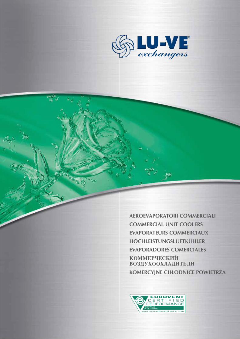
LU-VE S.p.A. - Uboldo (VA) Italy
Heat exchangers for industrial and commercial refrigeration, air conditioning and industrial applications.
LU-VE S.p.A. is the holding company of LU-VE Group. In 1985 LU-VE S.p.A. acquired Contardo S.p.A., established in 1928. Production began in 1986. LU-VE quickly made its mark thanks to high standards of quality, new solutions designed in its own laboratories and to the care taken with the appearance of its products. (Beautiful outside - Revolutionary inside).
LU-VE WAS THE FIRST COMPANY IN THE WORLD TO APPLY AVANT-GARDE SOLUTIONS TO COMMERCIAL AND INDUSTRIAL REFRIGERATION:
• GROOVED TUBE TECHNOLOGY • SPECIALIZED HEAT EXCHANGE SURFACES • CERTIFIED PERFORMANCE LEVELS • INNOVATIVE MATERIALS AND COLOURS • ADVANCED DESIGN.
The success of LU-VE in the international market stems from its research and development policy, its great respect for the environment and its rigorous ethical and commercial principles. In 2000, LU-VEwasthefirstcompanyinEuropetoattaintheprestigiousEurovent “Certify-All”certificationfortheentire range of its products: unit coolers, condensers and dry coolers. LU-VE and the Group have introduced new ways of conceiving and constructing products for refrigeration, air conditioning and industrial applications, creating new technologies which have then gone on to become the benchmark for the entire industry.
10
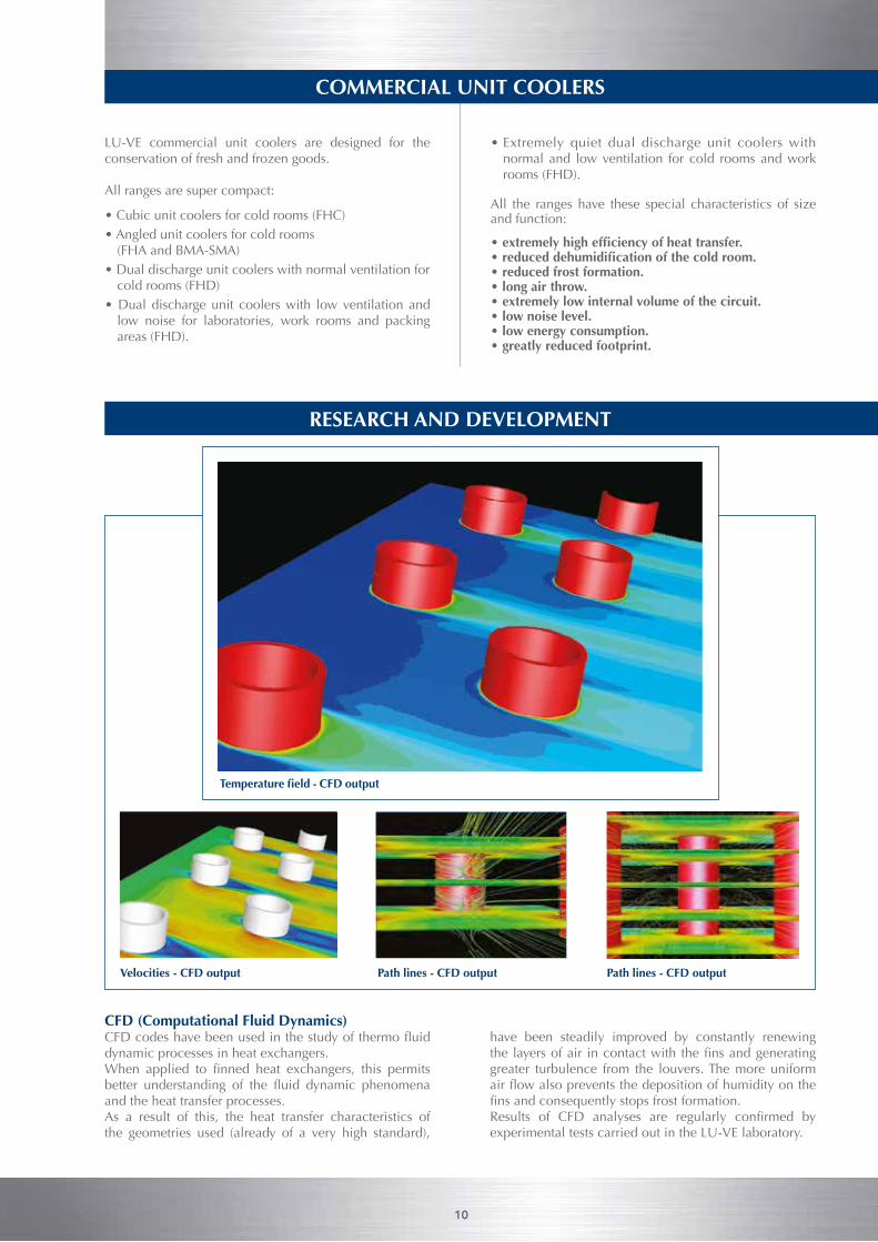
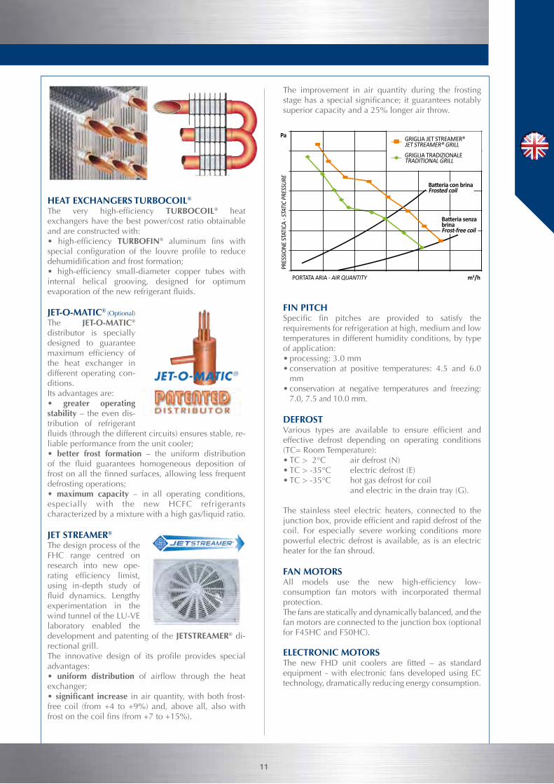
CFD (Computational Fluid Dynamics)CFDcodeshavebeenusedinthestudyofthermofluiddynamic processes in heat exchangers. When applied to finned heat exchangers, this permitsbetter understanding of the fluid dynamic phenomenaand the heat transfer processes. As a result of this, the heat transfer characteristics of the geometries used (already of a very high standard),
have been steadily improved by constantly renewing the layersofair incontactwith thefinsandgeneratinggreater turbulence from the louvers. The more uniform airflowalsopreventsthedepositionofhumidityonthefinsandconsequentlystopsfrostformation.Results of CFD analyses are regularly confirmed byexperimental tests carried out in the LU-VE laboratory.
RESEARCH AND DEVELOPMENT
Velocities - CFD output Path lines - CFD output Path lines - CFD output
Temperature field - CFD output
COMMERCIAL UNIT COOLERS
LU-VE commercial unit coolers are designed for the conservation of fresh and frozen goods.
All ranges are super compact:
• Cubic unit coolers for cold rooms (FHC) • Angled unit coolers for cold rooms
(FHA and BMA-SMA) • Dual discharge unit coolers with normal ventilation for
cold rooms (FHD)• Dual discharge unit coolers with low ventilation and
low noise for laboratories, work rooms and packing areas (FHD).
• Extremely quiet dual discharge unit coolers with normal and low ventilation for cold rooms and work rooms (FHD).
All the ranges have these special characteristics of size and function:
• extremely high efficiency of heat transfer.• reduced dehumidification of the cold room. • reduced frost formation. • long air throw.• extremely low internal volume of the circuit.• low noise level. • low energy consumption. • greatly reduced footprint.
HEAT EXCHANGERS TURBOCOIL®
The very high-efficiency TURBOCOIL® heat exchangers have the best power/cost ratio obtainable and are constructed with: • high-efficiency TURBOFIN® aluminum fins withspecial configuration of the louvre profile to reducedehumidificationandfrostformation;• high-efficiency small-diameter copper tubes withinternal helical grooving, designed for optimum evaporationofthenewrefrigerantfluids.
JET-O-MATIC® (Optional)
The JET-O-MATIC® distributor is specially designed to guarantee maximum efficiency ofthe heat exchanger in different operating con-ditions. Its advantages are:• greater operating stability – the even dis-tribution of refrigerant fluids(throughthedifferentcircuits)ensuresstable,re-liable performance from the unit cooler; • better frost formation – the uniform distribution of the fluid guarantees homogeneous deposition offrostonallthefinnedsurfaces,allowinglessfrequentdefrosting operations;• maximum capacity – in all operating conditions, especially with the new HCFC refrigerants characterized by a mixture with a high gas/liquid ratio.
JET STREAMER®
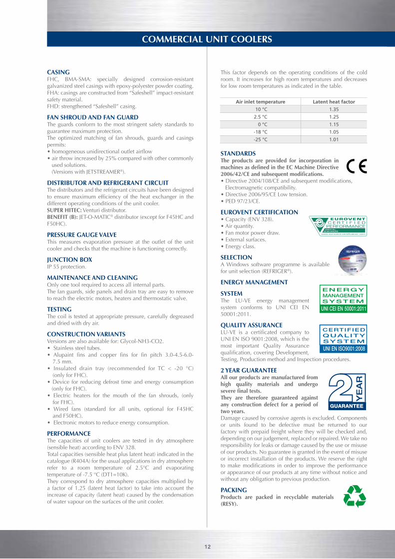
The design process of the FHC range centred on research into new ope-rating efficiency limist,using in-depth study of fluid dynamics. Lengthyexperimentation in the wind tunnel of the LU-VE laboratory enabled the development and patenting of the JETSTREAMER® di-rectional grill. The innovative design of its profile provides specialadvantages:• uniform distribution of airflow through the heatexchanger;• significant increase in air quantity, with both frost-free coil (from +4 to +9%) and, above all, also with frostonthecoilfins(from+7to+15%).
The improvement in air quantity during the frosting stagehasaspecialsignificance;itguaranteesnotablysuperior capacity and a 25% longer air throw.
FIN PITCHSpecific fin pitches are provided to satisfy therequirements for refrigeration at high, medium and low temperatures in different humidity conditions, by type of application:• processing: 3.0 mm• conservation at positive temperatures: 4.5 and 6.0
mm• conservation at negative temperatures and freezing:
7.0, 7.5 and 10.0 mm.
DEFROSTVarious types are available to ensure efficient andeffective defrost depending on operating conditions (TC= Room Temperature):• TC > 2°C air defrost (N)• TC > -35°C electric defrost (E)• TC > -35°C hot gas defrost for coil and electric in the drain tray (G).
The stainless steel electric heaters, connected to the junctionbox,provideefficientandrapiddefrostofthecoil. For especially severe working conditions more powerful electric defrost is available, as is an electric heater for the fan shroud.
FAN MOTORSAll models use the new high-efficiency low-consumption fan motors with incorporated thermal protection. The fans are statically and dynamically balanced, and the fan motors are connected to the junction box (optional for F45HC and F50HC).
ELECTRONIC MOTORSThe new FHD unit coolers are fitted – as standardequipment - with electronic fans developed using EC technology, dramatically reducing energy consumption.
GRIGLIA JET STREAMER®JET STREAMER® GRILL
Batteria con brinaFrosted coil
Batteria senza brinaFrost-free coil
GRIGLIA TRADIZIONALETRADITIONAL GRILL
PORTATA ARIA - AIR QUANTITY m3/h
Pa
PRES
SION
E ST
ATIC
A - S
TATI
C PR
ESSU
RE
11
12
COMMERCIAL UNIT COOLERS
Air inlet temperature Latent heat factor
10 °C 1.35
2.5 °C 1.25
0 °C 1.15
-18 °C 1.05
-25 °C 1.01
CASINGFHC, BMA-SMA: specially designed corrosion-resistant galvanized steel casings with epoxy-polyester powder coating.FHA: casings are constructed from “Safeshell” impact-resistant safety material.FHD: strengthened “Safeshell” casing.
FAN SHROUD AND FAN GUARD The guards conform to the most stringent safety standards to guarantee maximum protection. The optimized matching of fan shrouds, guards and casings permits:•homogeneousunidirectionaloutletairflow• air throw increased by 25% compared with other commonly used solutions. (Versions with JETSTREAMER®).
DISTRIBUTOR AND REFRIGERANT CIRCUITThe distributors and the refrigerant circuits have been designed to ensuremaximum efficiency of the heat exchanger in thedifferent operating conditions of the unit cooler. SUPER HITEC: Venturi distributor. BENEFIT (B): JET-O-MATIC® distributor (except for F45HC and F50HC).
PRESSURE GAUGE VALVE This measures evaporation pressure at the outlet of the unit cooler and checks that the machine is functioning correctly.
JUNCTION BOXIP 55 protection.
MAINTENANCE AND CLEANINGOnly one tool required to access all internal parts. The fan guards, side panels and drain tray are easy to remove to reach the electric motors, heaters and thermostatic valve.
TESTINGThe coil is tested at appropriate pressure, carefully degreased and dried with dry air.
CONSTRUCTION VARIANTSVersions are also available for: Glycol-NH3-CO2.• Stainless steel tubes.• Alupaint fins and copper fins for fin pitch 3.0-4.5-6.0-
7.5 mm.• Insulated drain tray (recommended for TC < -20 °C)
(only for FHC).• Device for reducing defrost time and energy consumption (only for FHC).• Electric heaters for the mouth of the fan shrouds, (only
for FHC).• Wired fans (standard for all units, optional for F45HC
and F50HC).• Electronic motors to reduce energy consumption.
PERFORMANCEThe capacities of unit coolers are tested in dry atmosphere (sensible heat) according to ENV 328.Total capacities (sensible heat plus latent heat) indicated in the catalogue (R404A) for the usual applications in dry atmosphere refer to a room temperature of 2.5°C and evaporating temperature of -7.5 °C (DT1=10K). They correspond to dry atmosphere capacities multiplied by a factor of 1.25 (latent heat factor) to take into account the increase of capacity (latent heat) caused by the condensation of water vapour on the surfaces of the unit cooler.
This factor depends on the operating conditions of the cold room. It increases for high room temperatures and decreases for low room temperatures as indicated in the table.
STANDARDSThe products are provided for incorporation in machines as defined in the EC Machine Directive 2006/42/CE and subsequent modifications.•Directive2004/108/CEandsubsequentmodifications, Electromagnetic compatibility.• Directive 2006/95/CE Low tension.• PED 97/23/CE.
EUROVENT CERTIFICATION• Capacity (ENV 328).• Air quantity.• Fan motor power draw. • External surfaces.• Energy class.
SELECTIONA Windows software programme is available for unit selection (REFRIGER®).
ENERGY MANAGEMENT
SYSTEMThe LU-VE energy management system conforms to UNI CEI EN 50001:2011.
QUALITY ASSURANCELU-VE is a certificated company toUNI EN ISO 9001:2008, which is the most important Quality Assurancequalification,coveringDevelopment,Testing, Production method and Inspection procedures.
2 YEAR GUARANTEE All our products are manufactured from high quality materials and undergo severe final tests. They are therefore guaranteed against any construction defect for a period of two years. Damage caused by corrosive agents is excluded. Components or units found to be defective must be returned to our factory with prepaid freight where they will be checked and, depending on our judgement, replaced or repaired. We take no responsibility for leaks or damage caused by the use or misuse of our products. No guarantee is granted in the event of misuse or incorrect installation of the products. We reserve the right tomakemodifications in order to improve the performanceor appearance of our products at any time without notice and without any obligation to previous production.
PACKINGProducts are packed in recyclable materials (RESY).
CERTIFY ALLDX AIR COOLERS
GUARANTEE
YE
AR
UNI EN ISO9001:2008
CERTIFIEDQUALITYSYSTEM
UNI CEI EN 50001:2011
ENERGYMANAGEMENTSYSTEM
UNI EN ISO9001:2008
CERTIFIEDQUALITYSYSTEM
UNI CEI EN 50001:2011
ENERGYMANAGEMENTSYSTEM
13
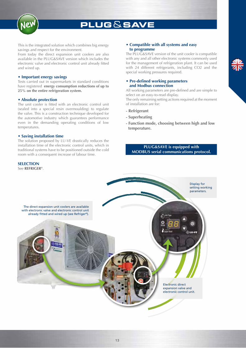
This is the integrated solution which combines big energy savings and respect for the environment. From today the direct expansion unit coolers are also available in the PLUG&SAVE version which includes the electronicvalveandelectroniccontrolunitalreadyfittedand wired up. • Important energy savingsTests carried out in supermarkets in standard conditions have registered energy consumption reductions of up to 25% on the entire refrigeration system.
• Absolute protectionTheunit cooler is fittedwith an electronic control unit(sealed into a special resin overmoulding) to regulate the valve. This is a construction technique developed for the automotive industry which guarantees performance even in the demanding operating conditions of low temperatures.
• Saving installation timeThe solution proposed by LU-VE drastically reduces the installation time of the electronic control units, which in traditional systems have to be positioned outside the cold room with a consequent increase of labour time.
• Compatible with all systems and easy to programme
The PLUG&SAVE version of the unit cooler is compatible with any and all other electronic systems commonly used for the management of refrigeration plant. It can be used with 24 different refrigerants, including CO2 and the special working pressures required.
• Pre-defined working parameters and Modbus connection
Allworkingparametersarepre-definedandaresimpletoselect on an easy-to-read display.The only remaining setting actions required at the moment of installation are for:
- Refrigerant
- Superheating
- Function mode, choosing between high and low temperature.
PLUG&SAVE is equipped with MODBUS serial communications protocol.
The direct expansion unit coolers are available with electronic valve and electronic control unit
already fitted and wired up (see Refriger®).
Display for setting working parameters.
Electronic direct expansion valve and electronic control unit.
SELECTIONSee REFRIGER®.
14
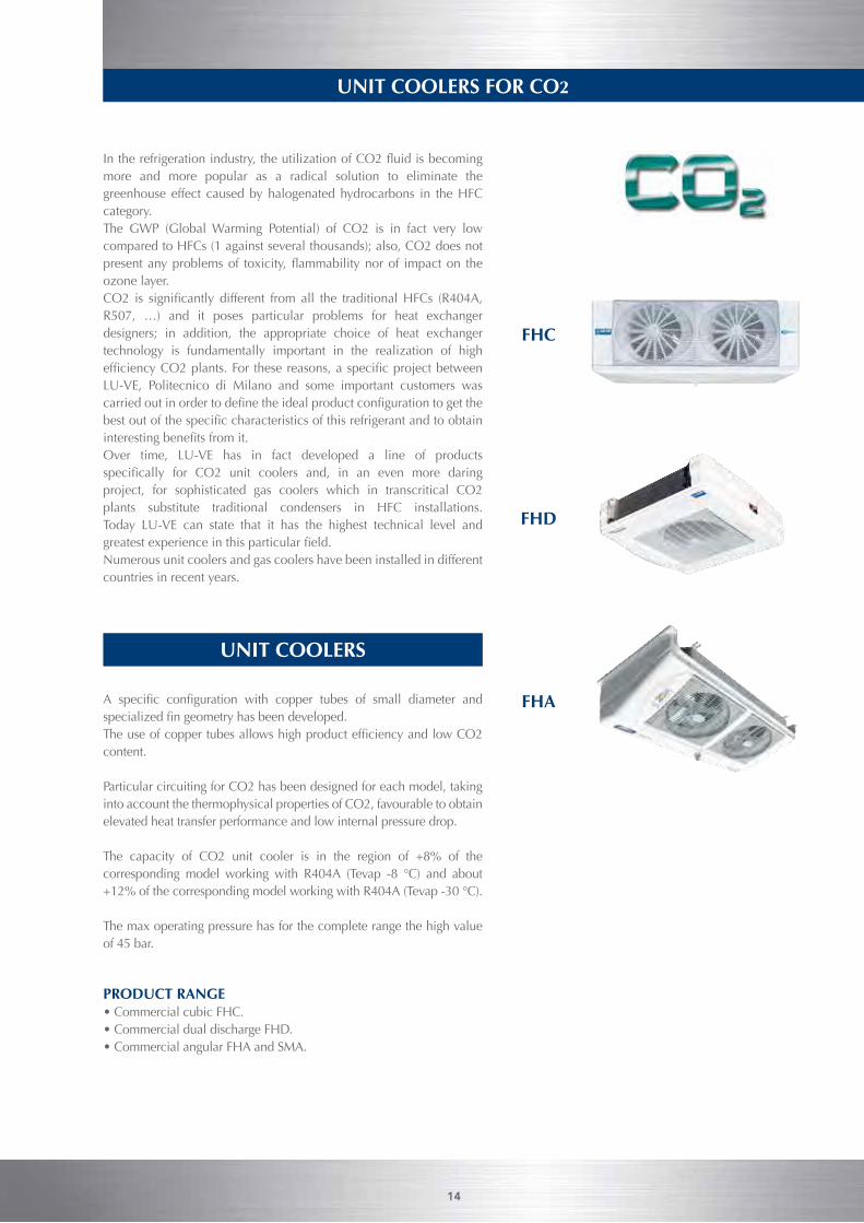
Intherefrigerationindustry,theutilizationofCO2fluidisbecomingmore and more popular as a radical solution to eliminate the greenhouse effect caused by halogenated hydrocarbons in the HFC category. The GWP (Global Warming Potential) of CO2 is in fact very low compared to HFCs (1 against several thousands); also, CO2 does not presentanyproblemsof toxicity,flammabilitynorof impacton theozone layer.CO2 is significantly different from all the traditionalHFCs (R404A,R507, …) and it poses particular problems for heat exchanger designers; in addition, the appropriate choice of heat exchanger technology is fundamentally important in the realization of high efficiencyCO2plants.For thesereasons,aspecificprojectbetweenLU-VE, Politecnico di Milano and some important customers was carriedoutinordertodefinetheidealproductconfigurationtogetthebestoutofthespecificcharacteristicsofthisrefrigerantandtoobtaininterestingbenefitsfromit.Over time, LU-VE has in fact developed a line of products specifically for CO2 unit coolers and, in an even more daringproject, for sophisticated gas coolers which in transcritical CO2 plants substitute traditional condensers in HFC installations.Today LU-VE can state that it has the highest technical level and greatestexperienceinthisparticularfield.Numerous unit coolers and gas coolers have been installed in different countries in recent years.
A specific configuration with copper tubes of small diameter andspecializedfingeometryhasbeendeveloped.TheuseofcoppertubesallowshighproductefficiencyandlowCO2content.
Particular circuiting for CO2 has been designed for each model, taking into account the thermophysical properties of CO2, favourable to obtain elevated heat transfer performance and low internal pressure drop.
The capacity of CO2 unit cooler is in the region of +8% of the corresponding model working with R404A (Tevap -8 °C) and about +12% of the corresponding model working with R404A (Tevap -30 °C).
The max operating pressure has for the complete range the high value of 45 bar.
PRODUCT RANGE • Commercial cubic FHC. • Commercial dual discharge FHD. • Commercial angular FHA and SMA.
UNIT COOLERS
UNIT COOLERS FOR CO2
14
FHC
FHD
FHA
15
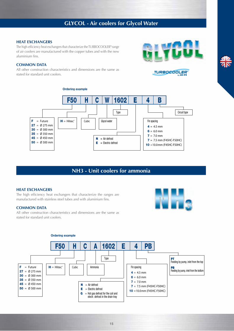
HEAT EXCHANGERS Thehigh-efficiencyheatexchangersthatcharacterizetheTURBOCOOLER® range of air coolers are manufactured with the copper tubes and with the new aluminiumfins.
COMMON DATA All other construction characteristics and dimensions are the same as stated for standard unit coolers.
HEAT EXCHANGERS The high efficiency heat exchangers that characterize the ranges aremanufacturedwithstainlesssteeltubesandwithaluminiumfins.
COMMON DATA All other construction characteristics and dimensions are the same as stated for standard unit coolers.
NH3 - Unit coolers for ammonia
GLYCOL - Air coolers for Glycol Water
15
Fin spacing
Type
==
Glycol water
Circuit type
F50 H C 1602 E 4 BW
F = Future27 = Ø 275 mm30 = Ø 300 mm35 = Ø 350 mm
= Ø 450 mm4550 = Ø 500 mm
H = Hitec® Cubic
4 = 4.5 mm6 = 6.0 mm7 = 7.0 mm7 = 7.5 mm (F45HC-F50HC)
10 =10.0mm (F45HC-F50HC)
N = Air defrostE = Electric defrost
Fin spacing
Type
F50 H C 1602 E 4 PBA
F = Future27 = Ø 275 mm30 = Ø 300 mm35 = Ø 350 mm
= Ø 450 mm4550 = Ø 500 mm
H = Hitec® Cubic
4 = 4.5 mm6 = 6.0 mm7 = 7.0 mm7 = 7.5 mm (F45HC-F50HC)
10 =10.0mm (F45HC-F50HC)
Ammonia
N = Air defrostE = Electric defrost
PTFeeding by pump, inlet from the top
PBFeeding by pump, inlet from the bottom
G = Hot gas defrost for the coil andelectr. defrost in the drain tray
Passo aletteFin spacingPas des ailettesLamellenabstandPaso de aletasШаг лameлeй Podziałka lamel
4 = 4,5 mm6 = 6,0 mm7 = 7,5 mm
10 = 10,0 mm12 = 12,0 mm
CS = Compact SurfaceLS = Large Surface
H = Hitec®
Ventilatori (Altezza moduli)Fans (Height modules)Ventilateurs (Hauteur modules)Ventilatoren (Höhe module)VeВентиляторы
ntiladores (Altura modulos)
(Высота единиц)
Wentilatory (Wysokość modułów)
45 = Ø 450 mm (550 mm)
50 = Ø 500 mm (770 mm)
62 = Ø 630 mm (770 mm)
71 = Ø 710 mm (990 mm)
80 = Ø 800 mm (1250 mm)
ModelloType ModèleModellModeloМодельModel
CS 62 H 2214 E 6
N = Sbrinamento ad ariaE = Sbrinamento elettricoSB = Sbrinamento ad acquaG = Sbrinamento a gas caldo per
batteria ed elettrico nella bacinellaGB= Sbrinamento a gas caldo per
batteria e bacinella
N = Воздушная разморозкаE = Электрическая разморозкаSB = Водяная разморозкаG = Разморозка горячим газом для
теплообменника и электрическая разморозка для дренажного контейнера= разморозка горячим газом и для теплообменника и для дренажного контейнера
GB
N = Odszranianie powietrzemE = Odszranianie elektryczneSB = Odszranianie wodąG = Odszranianie gorącym gazem w
wymienniku i elektryczne w tacyGB= Odszranianie gorącym gazem w
wymienniku i tacy
N = Air defrostE = Electric defrostSB = Water spray defrostG = Hot gas defrost for the coil and
electr. defrost in the drain trayGB= Hot gas defrost for
both coil and drain tray
N = Dégivrage à airE = Dégivrage électriqueSB = Dégivrage à eauG = Dégivrage à gaz chaud
pour la batterie etélectrique dans l’egouttoire
GB= Dégivrage à gazchaud pour la batterieet l’egouttoire
N = LuftabtauungE = Elektrische AbtauungSB = WasserabtauungG = Heissgasabtauung für die
Batterie und elektrische Abtauung in der Tropfschale
GB= Heissgasabtauung fürdie Batterie und Tropf-schale
N = Desescarche por aireE = Desescarche eléctricoSB = Desescarche por aguaG = Desescarche por gas
caliente en bateria yeléctrico en bandeja
GB= Desescarche por gascaliente en bateria ybandeja
Metodo di sceltadell’aeroevaporatore
Unit cooler model selection
Méthode de sélection de l’évaporateur
Auswahlmethoden für Hochleistungsluftkühler
Метод выбора
Dobór chłodnicy powietrza
Método de selección de evaporador
Scelta rapida Quick selection Sélection rapide Schnellauswahl Selección rápida Мгновенный подбор Szybki dobór
TC = 0°C UR = 85% ∆T1 = 7 K CT = 53 kWFreccia d’aria Air throw Projection de l’aire Wurfweite Dardo de aire Воздушный поток Zasięg strumienia powietrza
Шаг ламелей Podziałka lamel
= 48 mFluido refrigerante Refrigerant fluid Fluide réfrigérant Kältemittel Refrigerante Хладагент Czynnik chłodniczy = R404APasso alette Fin spacing Pas des ailettes Lamellenabstand Paso aletas = 6,0 mm
CT x 1/FC = 53 x 1/0,65 = 81,5 kWSelezione / Selection / Sélection / Typenauswahl / Selección / Bыбор / Wybór = CS62H2214E6 Potenza / Rating / Puissance / Leistung / Potencia / Bласть / Moc = ∆T1 10K = 82,3 kW (Catalogo / Catalogue / Catalogue / Katalog
Catálogo / Kаталог/ Katalog)∆T1 = 81,5/82,3 x 7 = 6,9 KTE = TC - ∆T1 = 0 - 6,9 = - 6,9 °C
socisäb sotaDnetaD-sisaBesab ed seénnoDatad cisaBesab id itaD
Nota
Внимание Uwagi
Un'analoga potenza è ot-tenibile con differente:• Modello• Ø x n° ventilatori• Portata d’aria• Freccia d’aria• Superficie• Sbrinamento (E)• Dimensioni
NoteA similar capacity is obtai-nable with different:• Type• Ø x n° fans• Air quantity• Air throw• Surface• Defrost (E)• Dimensions
•
•
Mодель
Одинаковая мощность получается различными:
• Ø x n° вентиляторы• Воздушный факел
• Podobną wydajność można uzyskać poprzez zmianę:
• Объем воздуха• Поверхность• Разморозка (E)• Размеры
• Przepływ powietrza• Zasięgu strumienia powietrza• Średnicy i liczby wentylatorów
• Powierzchnia• Rozmrażanie (E)• Wymiary
NoteOn peut obtenir une puis-sance identique avec diffé-rent:• Modèle• Ø x n° quantité de mo-
teurs• Débits d'air• Portées d'air• Surfaces• Dégivrages (E)• Dimensions
AnmerkungEine analoge Leistung isterreichbar mit Änderungvon:• Modell• Ø x n° Motorenanzahl• Luftdurchsatz• Wurfweite• Fläche• Abtauung (E)• Abmessungen
NoteUna potencia similar seobtiene con diferente:• Modelo• Ø x n° motores• Caudal de aire• Dardo de aire• Superficie• Desescarche (E)• Dimensiones
Основные данные Dane podstawowe
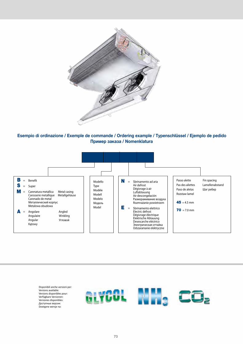
Esempio di ordinazione / Exemple de commande / Ordering example / Typenschlüssel / Ejemplo de pedidoПример заказа / Nomenklatura
Passo aletteFin spacingPas des ailettesLamellenabstandPaso de aletasШаг лameлeй Podziałka lamel
4 = 4,5 mm6 = 6,0 mm7 = 7,5 mm
10 = 10,0 mm12 = 12,0 mm
CS = Compact SurfaceLS = Large Surface
H = Hitec®
Ventilatori (Altezza moduli)Fans (Height modules)Ventilateurs (Hauteur modules)Ventilatoren (Höhe module)VeВентиляторы
ntiladores (Altura modulos)
(Высота единиц)
Wentilatory (Wysokość modułów)
45 = Ø 450 mm (550 mm)
50 = Ø 500 mm (770 mm)
62 = Ø 630 mm (770 mm)
71 = Ø 710 mm (990 mm)
80 = Ø 800 mm (1250 mm)
ModelloType ModèleModellModeloМодельModel
CS 62 H 2214 E 6
N = Sbrinamento ad ariaE = Sbrinamento elettricoSB = Sbrinamento ad acquaG = Sbrinamento a gas caldo per
batteria ed elettrico nella bacinellaGB= Sbrinamento a gas caldo per
batteria e bacinella
N = Воздушная разморозкаE = Электрическая разморозкаSB = Водяная разморозкаG = Разморозка горячим газом для
теплообменника и электрическая разморозка для дренажного контейнера= разморозка горячим газом и для теплообменника и для дренажного контейнера
GB
N = Odszranianie powietrzemE = Odszranianie elektryczneSB = Odszranianie wodąG = Odszranianie gorącym gazem w
wymienniku i elektryczne w tacyGB= Odszranianie gorącym gazem w
wymienniku i tacy
N = Air defrostE = Electric defrostSB = Water spray defrostG = Hot gas defrost for the coil and
electr. defrost in the drain trayGB= Hot gas defrost for
both coil and drain tray
N = Dégivrage à airE = Dégivrage électriqueSB = Dégivrage à eauG = Dégivrage à gaz chaud
pour la batterie etélectrique dans l’egouttoire
GB= Dégivrage à gazchaud pour la batterieet l’egouttoire
N = LuftabtauungE = Elektrische AbtauungSB = WasserabtauungG = Heissgasabtauung für die
Batterie und elektrische Abtauung in der Tropfschale
GB= Heissgasabtauung fürdie Batterie und Tropf-schale
N = Desescarche por aireE = Desescarche eléctricoSB = Desescarche por aguaG = Desescarche por gas
caliente en bateria yeléctrico en bandeja
GB= Desescarche por gascaliente en bateria ybandeja
Metodo di sceltadell’aeroevaporatore
Unit cooler model selection
Méthode de sélection de l’évaporateur
Auswahlmethoden für Hochleistungsluftkühler
Метод выбора
Dobór chłodnicy powietrza
Método de selección de evaporador
Scelta rapida Quick selection Sélection rapide Schnellauswahl Selección rápida Мгновенный подбор Szybki dobór
TC = 0°C UR = 85% ∆T1 = 7 K CT = 53 kWFreccia d’aria Air throw Projection de l’aire Wurfweite Dardo de aire Воздушный поток Zasięg strumienia powietrza
Шаг ламелей Podziałka lamel
= 48 mFluido refrigerante Refrigerant fluid Fluide réfrigérant Kältemittel Refrigerante Хладагент Czynnik chłodniczy = R404APasso alette Fin spacing Pas des ailettes Lamellenabstand Paso aletas = 6,0 mm
CT x 1/FC = 53 x 1/0,65 = 81,5 kWSelezione / Selection / Sélection / Typenauswahl / Selección / Bыбор / Wybór = CS62H2214E6 Potenza / Rating / Puissance / Leistung / Potencia / Bласть / Moc = ∆T1 10K = 82,3 kW (Catalogo / Catalogue / Catalogue / Katalog
Catálogo / Kаталог/ Katalog)∆T1 = 81,5/82,3 x 7 = 6,9 KTE = TC - ∆T1 = 0 - 6,9 = - 6,9 °C
socisäb sotaDnetaD-sisaBesab ed seénnoDatad cisaBesab id itaD
Nota
Внимание Uwagi
Un'analoga potenza è ot-tenibile con differente:• Modello• Ø x n° ventilatori• Portata d’aria• Freccia d’aria• Superficie• Sbrinamento (E)• Dimensioni
NoteA similar capacity is obtai-nable with different:• Type• Ø x n° fans• Air quantity• Air throw• Surface• Defrost (E)• Dimensions
•
•
Mодель
Одинаковая мощность получается различными:
• Ø x n° вентиляторы• Воздушный факел
• Podobną wydajność można uzyskać poprzez zmianę:
• Объем воздуха• Поверхность• Разморозка (E)• Размеры
• Przepływ powietrza• Zasięgu strumienia powietrza• Średnicy i liczby wentylatorów
• Powierzchnia• Rozmrażanie (E)• Wymiary
NoteOn peut obtenir une puis-sance identique avec diffé-rent:• Modèle• Ø x n° quantité de mo-
teurs• Débits d'air• Portées d'air• Surfaces• Dégivrages (E)• Dimensions
AnmerkungEine analoge Leistung isterreichbar mit Änderungvon:• Modell• Ø x n° Motorenanzahl• Luftdurchsatz• Wurfweite• Fläche• Abtauung (E)• Abmessungen
NoteUna potencia similar seobtiene con diferente:• Modelo• Ø x n° motores• Caudal de aire• Dardo de aire• Superficie• Desescarche (E)• Dimensiones
Основные данные Dane podstawowe
Esempio di ordinazione / Exemple de commande / Ordering example / Typenschlüssel / Ejemplo de pedidoПример заказа / Nomenklatura
CERTIFY ALLDX AIR COOLERS
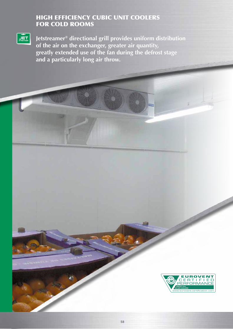
HIGH EFFICIENCY CUBIC UNIT COOLERS FOR COLD ROOMS
Jetstreamer® directional grill provides uniform distribution of the air on the exchanger, greater air quantity,greatly extended use of the fan during the defrost stage and a particularly long air throw.
58
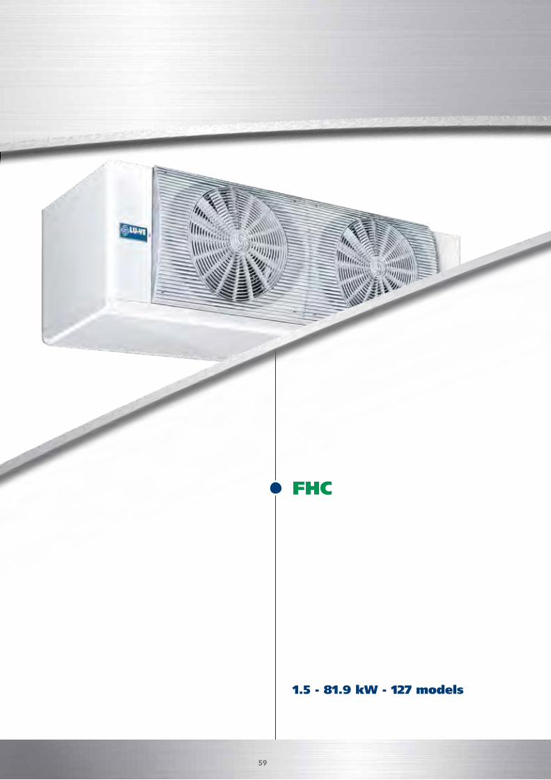
1.5 - 81.9 kW - 127 models
FHC
HIGH EFFICIENCY CUBIC UNIT COOLERS FOR COLD ROOMS
Jetstreamer® directional grill provides uniform distribution of the air on the exchanger, greater air quantity,greatly extended use of the fan during the defrost stage and a particularly long air throw.
59
Aeroevaporatori per celle frigorifereUnit coolers for cold rooms
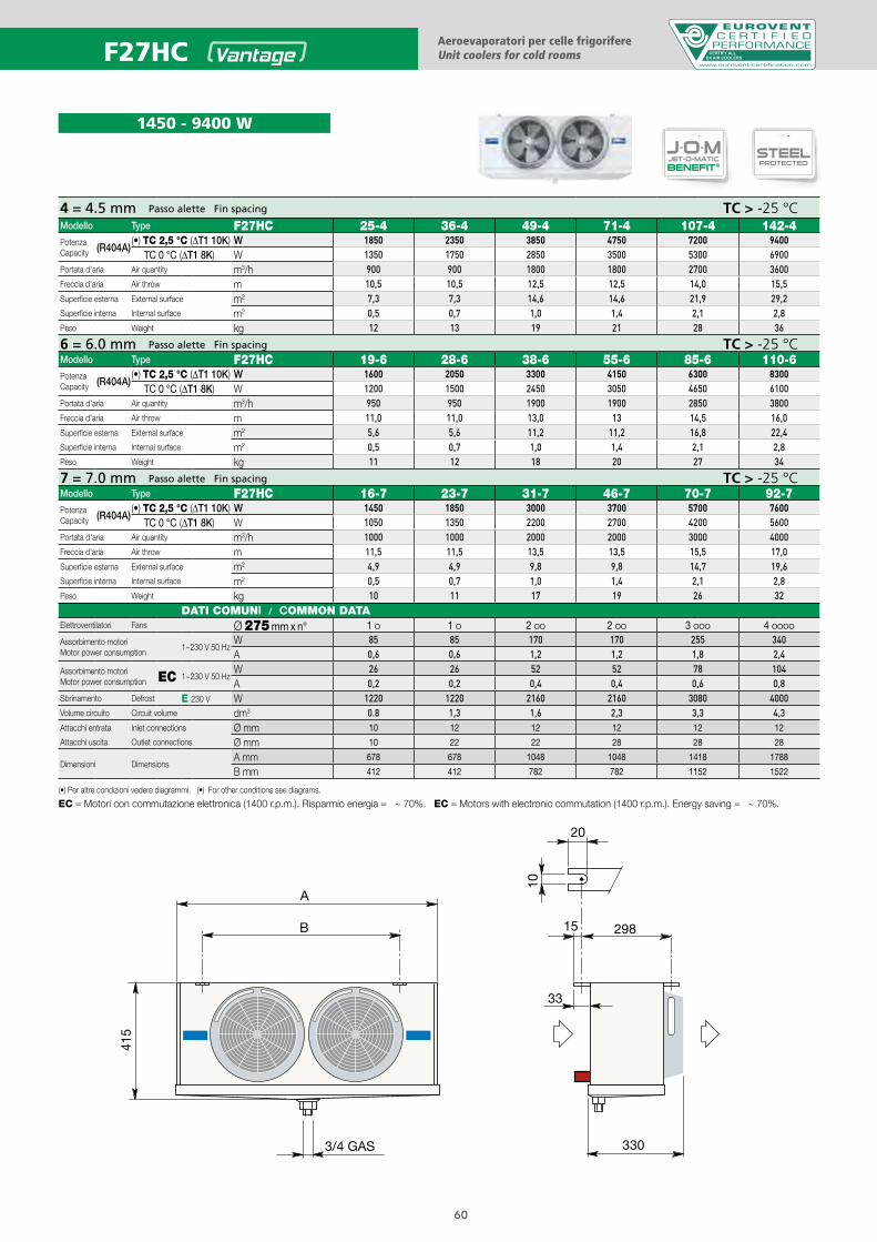
1450 - 9400 W
CERTIFY ALLDX AIR COOLERS
4 = 4.5 mm Passo alette Fin spacing TC > -25 °CModello Type F27HC 25-4 36-4 49-4 71-4 107-4 142-4PotenzaCapacity (R404A)
(•) TC 2,5 °C (ΔT1 10K) W 1850 2350 3850 4750 7200 9400TC 0 °C (ΔT1 8K) W 1350 1750 2850 3500 5300 6900
Portata d'aria Air quantity m3/h 900 900 1800 1800 2700 3600Freccia d'aria Air throw m 10,5 10,5 12,5 12,5 14,0 15,5Superficie esterna External surface m2 7,3 7,3 14,6 14,6 21,9 29,2Superficie interna Internal surface m2 0,5 0,7 1,0 1,4 2,1 2,8Peso Weight kg 12 13 19 21 28 36
6 = 6.0 mm Passo alette Fin spacing TC > -25 °CModello Type F27HC 19-6 28-6 38-6 55-6 85-6 110-6PotenzaCapacity (R404A)
(•) TC 2,5 °C (ΔT1 10K) W 1600 2050 3300 4150 6300 8300TC 0 °C (ΔT1 8K) W 1200 1500 2450 3050 4650 6100
Portata d'aria Air quantity m3/h 950 950 1900 1900 2850 3800Freccia d'aria Air throw m 11,0 11,0 13,0 13 14,5 16,0Superficie esterna External surface m2 5,6 5,6 11,2 11,2 16,8 22,4Superficie interna Internal surface m2 0,5 0,7 1,0 1,4 2,1 2,8Peso Weight kg 11 12 18 20 27 34
7 = 7.0 mm Passo alette Fin spacing TC > -25 °CModello Type F27HC 16-7 23-7 31-7 46-7 70-7 92-7PotenzaCapacity (R404A)
(•) TC 2,5 °C (ΔT1 10K) W 1450 1850 3000 3700 5700 7600TC 0 °C (ΔT1 8K) W 1050 1350 2200 2700 4200 5600
Portata d'aria Air quantity m3/h 1000 1000 2000 2000 3000 4000Freccia d'aria Air throw m 11,5 11,5 13,5 13,5 15,5 17,0Superficie esterna External surface m2 4,9 4,9 9,8 9,8 14,7 19,6Superficie interna Internal surface m2 0,5 0,7 1,0 1,4 2,1 2,8Peso Weight kg 10 11 17 19 26 32
DATI COMUNI / COMMON DATAElettroventilatori Fans Ø 275 mm x n° 1 O 1 O 2 OO 2 OO 3 OOO 4 OOOO
Assorbimento motoriMotor power consumption
1~230 V 50 HzW 85 85 170 170 255 340A 0,6 0,6 1,2 1,2 1,8 2,4
Assorbimento motoriMotor power consumption EC 1~230 V 50 Hz
W 26 26 52 52 78 104A 0,2 0,2 0,4 0,4 0,6 0,8
Sbrinamento Defrost E 230 V W 1220 1220 2160 2160 3080 4000Volume circuito Circuit volume dm3 0.8 1,3 1,6 2,3 3,3 4,3Attacchi entrata Inlet connections Ø mm 10 12 12 12 12 12
Attacchi uscita Outlet connections Ø mm 10 22 22 28 28 28
Dimensioni DimensionsA mm 678 678 1048 1048 1418 1788
B mm 412 412 782 782 1152 1522
DUALDISCHARGE
STSSAFETUBES
SYSTEM
SMARTPATENTED
JETSTREAMER
J-O-MJET-O-MATIC
BENEFIT®STEELPROTECTED
DUALDISCHARGE
STSSAFETUBES
SYSTEM
SMARTPATENTED
JETSTREAMER
J-O-MJET-O-MATIC
BENEFIT®STEELPROTECTED
F27HC
(•) Per altre condizioni vedere diagrammi. (•) For other conditions see diagrams.
EC = Motori con commutazione elettronica (1400 r.p.m.). Risparmio energia = ~ 70%. EC = Motors with electronic commutation (1400 r.p.m.). Energy saving = ~ 70%.
60
DUALDISCHARGE
STSSAFETUBES
SYSTEM
SMARTPATENTED
JETSTREAMER
J-O-MJET-O-MATIC
BENEFIT®STEELPROTECTED
DUALDISCHARGE
STSSAFETUBES
SYSTEM
SMARTPATENTED
JETSTREAMER
J-O-MJET-O-MATIC
BENEFIT®STEELPROTECTED
DUALDISCHARGE
STSSAFETUBES
SYSTEM
SMARTPATENTED
JETSTREAMER
J-O-MJET-O-MATIC
BENEFIT®STEELPROTECTED
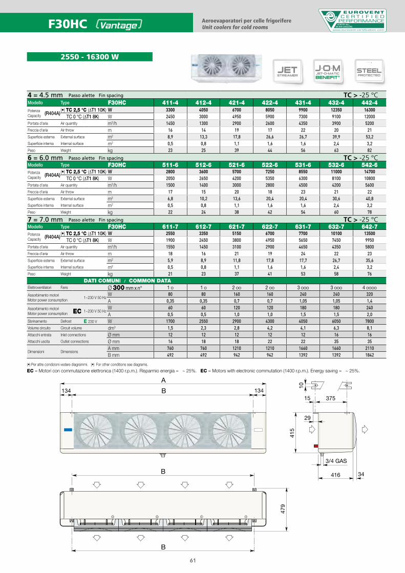
2550 - 16300 W
4 = 4.5 mm Passo alette Fin spacing TC > -25 °CModello Type F30HC 411-4 412-4 421-4 422-4 431-4 432-4 442-4PotenzaCapacity (R404A)
(•) TC 2,5 °C (ΔT1 10K) W 3300 4050 6700 8050 9900 12350 16300TC 0 °C (ΔT1 8K) W 2450 3000 4950 5900 7300 9100 12000
Portata d'aria Air quantity m3/h 1450 1300 2900 2600 4350 3900 5200Freccia d'aria Air throw m 16 14 19 17 22 20 21Superficie esterna External surface m2 8,9 13,3 17,8 26,6 26,7 39,9 53,2Superficie interna Internal surface m2 0,5 0,8 1,1 1,6 1,6 2,4 3,2Peso Weight kg 23 25 39 44 56 63 82
6 = 6.0 mm Passo alette Fin spacing TC > -25 °CModello Type F30HC 511-6 512-6 521-6 522-6 531-6 532-6 542-6PotenzaCapacity (R404A)
(•) TC 2,5 °C (ΔT1 10K) W 2800 3600 5700 7250 8550 11000 14700TC 0 °C (ΔT1 8K) W 2050 2650 4200 5350 6300 8100 10800
Portata d'aria Air quantity m3/h 1500 1400 3000 2800 4500 4200 5600Freccia d'aria Air throw m 17 15 20 18 23 21 22Superficie esterna External surface m2 6,8 10,2 13,6 20,4 20,4 30,6 40,8Superficie interna Internal surface m2 0,5 0,8 1,1 1,6 1,6 2,4 3,2Peso Weight kg 22 24 38 42 54 60 78
7 = 7.0 mm Passo alette Fin spacing TC > -25 °CModello Type F30HC 611-7 612-7 621-7 622-7 631-7 632-7 642-7PotenzaCapacity (R404A)
(•) TC 2,5 °C (ΔT1 10K) W 2550 3350 5150 6700 7700 10100 13500TC 0 °C (ΔT1 8K) W 1900 2450 3800 4950 5650 7450 9950
Portata d'aria Air quantity m3/h 1550 1450 3100 2900 4650 4350 5800Freccia d'aria Air throw m 18 16 21 19 24 22 23Superficie esterna External surface m2 5,9 8,9 11,8 17,8 17,7 26,7 35,6Superficie interna Internal surface m2 0,5 0,8 1,1 1,6 1,6 2,4 3,2Peso Weight kg 21 23 37 41 53 58 76
DATI COMUNI / COMMON DATAElettroventilatori Fans Ø 300 mm x n° 1 O 1 O 2 OO 2 OO 3 OOO 3 OOO 4 OOOO
Assorbimento motoriMotor power consumption
1~230 V 50 HzW 80 80 160 160 240 240 320A 0,35 0,35 0,7 0,7 1,05 1,05 1,4
Assorbimento motoriMotor power consumption EC 1~230 V 50 Hz
W 60 60 120 120 180 180 240A 0,5 0,5 1,0 1,0 1,5 1,5 2,0
Sbrinamento Defrost E 230 V W 1700 2550 2900 4300 4050 6050 7800Volume circuito Circuit volume dm3 1,5 2,3 2,8 4,2 4,1 6,3 8,1Attacchi entrata Inlet connections Ø mm 12 12 12 12 12 16 16Attacchi uscita Outlet connections Ø mm 16 18 18 22 22 35 35
Dimensioni DimensionsA mm 760 760 1210 1210 1660 1660 2110B mm 492 492 942 942 1392 1392 1842
(•) Per altre condizioni vedere diagrammi. (•) For other conditions see diagrams.
EC = Motori con commutazione elettronica (1400 r.p.m.). Risparmio energia = ~ 25%. EC = Motors with electronic commutation (1400 r.p.m.). Energy saving = ~ 25%.
B
479
B
375
29
15
10
415
416 34
A
B134 134
3/4 GAS
F30HC Aeroevaporatori per celle frigorifereUnit coolers for cold rooms
CERTIFY ALLDX AIR COOLERS
61
B
C C
486
CC
B
375
29
15
10
487
416 44
AB134 134
3/4 GAS
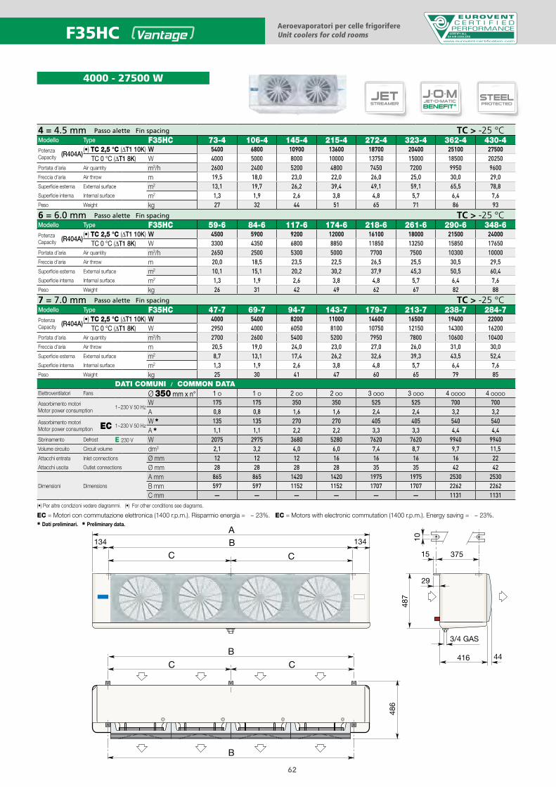
4 = 4.5 mm Passo alette Fin spacing TC > -25 °CModello Type F35HC 73-4 106-4 145-4 215-4 272-4 323-4 362-4 430-4PotenzaCapacity (R404A)
(•) TC 2,5 °C (ΔT1 10K) W 5400 6800 10900 13600 18700 20400 25100 27500TC 0 °C (ΔT1 8K) W 4000 5000 8000 10000 13750 15000 18500 20250
Portata d'aria Air quantity m3/h 2600 2400 5200 4800 7450 7200 9950 9600Freccia d'aria Air throw m 19,5 18,0 23,0 22,0 26,0 25,0 30,0 29,0Superficie esterna External surface m2 13,1 19,7 26,2 39,4 49,1 59,1 65,5 78,8Superficie interna Internal surface m2 1,3 1,9 2,6 3,8 4,8 5,7 6,4 7,6Peso Weight kg 27 32 44 51 65 71 86 93
6 = 6.0 mm Passo alette Fin spacing TC > -25 °CModello Type F35HC 59-6 84-6 117-6 174-6 218-6 261-6 290-6 348-6PotenzaCapacity (R404A)
(•) TC 2,5 °C (ΔT1 10K) W 4500 5900 9200 12000 16100 18000 21500 24000TC 0 °C (ΔT1 8K) W 3300 4350 6800 8850 11850 13250 15850 17650
Portata d'aria Air quantity m3/h 2650 2500 5300 5000 7700 7500 10300 10000Freccia d'aria Air throw m 20,0 18,5 23,5 22,5 26,5 25,5 30,5 29,5Superficie esterna External surface m2 10,1 15,1 20,2 30,2 37,9 45,3 50,5 60,4Superficie interna Internal surface m2 1,3 1,9 2,6 3,8 4,8 5,7 6,4 7,6Peso Weight kg 26 31 42 49 62 67 82 88
7 = 7.0 mm Passo alette Fin spacing TC > -25 °CModello Type F35HC 47-7 69-7 94-7 143-7 179-7 213-7 238-7 284-7PotenzaCapacity (R404A)
(•) TC 2,5 °C (ΔT1 10K) W 4000 5400 8200 11000 14600 16500 19400 22000TC 0 °C (ΔT1 8K) W 2950 4000 6050 8100 10750 12150 14300 16200
Portata d'aria Air quantity m3/h 2700 2600 5400 5200 7950 7800 10600 10400Freccia d'aria Air throw m 20,5 19,0 24,0 23,0 27,0 26,0 31,0 30,0Superficie esterna External surface m2 8,7 13,1 17,4 26,2 32,6 39,3 43,5 52,4Superficie interna Internal surface m2 1,3 1,9 2,6 3,8 4,8 5,7 6,4 7,6Peso Weight kg 25 30 41 47 60 65 79 85
DATI COMUNI / COMMON DATAElettroventilatori Fans Ø 350 mm x n° 1 O 1 O 2 OO 2 OO 3 OOO 3 OOO 4 OOOO 4 OOOO
Assorbimento motoriMotor power consumption
1~230 V 50 HzW 175 175 350 350 525 525 700 700A 0,8 0,8 1,6 1,6 2,4 2,4 3,2 3,2
Assorbimento motoriMotor power consumption EC 1~230 V 50 Hz
W * 135 135 270 270 405 405 540 540A * 1,1 1,1 2,2 2,2 3,3 3,3 4,4 4,4
Sbrinamento Defrost E 230 V W 2075 2975 3680 5280 7620 7620 9940 9940Volume circuito Circuit volume dm3 2,1 3,2 4,0 6,0 7,4 8,7 9,7 11,5Attacchi entrata Inlet connections Ø mm 12 12 12 16 16 16 16 22Attacchi uscita Outlet connections Ø mm 28 28 28 28 35 35 42 42
Dimensioni Dimensions
A mm 865 865 1420 1420 1975 1975 2530 2530B mm 597 597 1152 1152 1707 1707 2262 2262C mm — — — — — — 1131 1131
DUALDISCHARGE
STSSAFETUBES
SYSTEM
SMARTPATENTED
JETSTREAMER
J-O-MJET-O-MATIC
BENEFIT®STEELPROTECTED
DUALDISCHARGE
STSSAFETUBES
SYSTEM
SMARTPATENTED
JETSTREAMER
J-O-MJET-O-MATIC
BENEFIT®STEELPROTECTED
DUALDISCHARGE
STSSAFETUBES
SYSTEM
SMARTPATENTED
JETSTREAMER
J-O-MJET-O-MATIC
BENEFIT®STEELPROTECTED
Aeroevaporatori per celle frigorifereUnit coolers for cold rooms
4000 - 27500 W
CERTIFY ALLDX AIR COOLERSF35HC
(•) Per altre condizioni vedere diagrammi. (•) For other conditions see diagrams.
* Dati preliminari. * Preliminary data.
EC = Motori con commutazione elettronica (1400 r.p.m.). Risparmio energia = ~ 23%. EC = Motors with electronic commutation (1400 r.p.m.). Energy saving = ~ 23%.
62
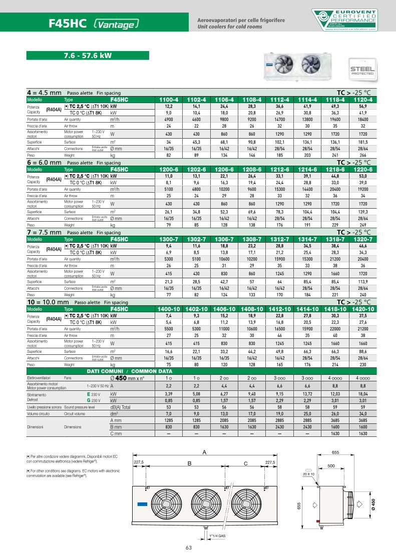
7.6 - 57.6 kW
F45HC Aeroevaporatori per celle frigorifereUnit coolers for cold rooms
CERTIFY ALLDX AIR COOLERS
4 = 4.5 mm Passo alette Fin spacing TC > -25 °CModello Type F45HC 1100-4 1102-4 1106-4 1108-4 1112-4 1114-4 1118-4 1120-4PotenzaCapacity (R404A)
(•) TC 2,5 °C (ΔT1 10K) kW 12,2 14,1 24,4 28,3 36,6 41,9 49,3 56,9TC 0 °C (ΔT1 8K) kW 9,0 10,4 18,0 20,8 26,9 30,8 36,3 41,9
Portata d'aria Air quantity m3/h 4900 4600 9800 9200 14700 13800 19600 18400Freccia d'aria Air throw m 24 22 28 26 32 30 35 32Assorbimento motori
Motor power consumption
1~230 V 50 Hz W 430 430 860 860 1290 1290 1720 1720
Superficie Surface m2 34 45,3 68,1 90,8 102,1 136,1 136,1 181,5Attacchi Connections Entrata-uscita
Inlet-outlet Ø mm 16/35 16/35 16/42 16/42 28/54 28/54 28/54 28/64Peso Weight kg 82 89 134 146 185 203 241 266
6 = 6.0 mm Passo alette Fin spacing TC > -25 °CModello Type F45HC 1200-6 1202-6 1206-6 1208-6 1212-6 1214-6 1218-6 1220-6PotenzaCapacity (R404A)
(•) TC 2,5 °C (ΔT1 10K) kW 11,0 13,1 22,1 26,4 33,1 39,1 44,8 53,0TC 0 °C (ΔT1 8K) kW 8,1 9,6 16,3 19,4 24,4 28,8 33,0 39,0
Portata d'aria Air quantity m3/h 5100 4800 10200 9600 15300 14400 20400 19200Freccia d'aria Air throw m 25 24 29 28 33 32 36 34Assorbimento motori
Motor power consumption
1~230 V 50 Hz W 430 430 860 860 1290 1290 1720 1720
Superficie Surface m2 26,1 34,8 52,3 69,6 78,3 104,4 104,4 139,3Attacchi Connections Entrata-uscita
Inlet-outlet Ø mm 16/35 16/35 16/42 16/42 28/54 28/54 28/54 28/64Peso Weight kg 79 85 128 138 176 191 229 249
7 = 7.5 mm Passo alette Fin spacing TC > -25 °CModello Type F45HC 1300-7 1302-7 1306-7 1308-7 1312-7 1314-7 1318-7 1320-7PotenzaCapacity (R404A)
(•) TC 2,5 °C (ΔT1 10K) kW 9,4 11,6 18,8 23,2 28,8 34,5 38,4 46,6TC 0 °C (ΔT1 8K) kW 6,9 8,5 13,8 17,1 21,2 25,4 28,3 34,3
Portata d'aria Air quantity m3/h 5300 5100 10600 10200 15900 15300 21200 20400Freccia d'aria Air throw m 26 25 31 29 35 33 38 36Assorbimento motori
Motor power consumption
1~230 V 50 Hz W 415 430 830 860 1245 1290 1660 1720
Superficie Surface m2 21,3 28,5 42,7 57 64 85,4 85,4 113,9Attacchi Connections Entrata-uscita
Inlet-outlet Ø mm 16/35 16/35 16/42 16/42 16/42 28/54 28/54 28/64Peso Weight kg 77 82 124 133 170 184 221 240
10 = 10.0 mm Passo alette Fin spacing TC > -25 °CModello Type F45HC 1400-10 1402-10 1406-10 1408-10 1412-10 1414-10 1418-10 1420-10PotenzaCapacity (R404A)
(•) TC 2,5 °C (ΔT1 10K) kW 7,4 9,3 15,2 18,9 22,8 27,8 30,3 37,5TC 0 °C (ΔT1 8K) kW 5,4 6,8 11,2 13,9 16,8 20,5 22,3 27,6
Portata d'aria Air quantity m3/h 5500 5300 11000 10600 16500 15900 22000 21200Freccia d'aria Air throw m 27 25 32 30 46 35 40 38Assorbimento motori
Motor power consumption
1~230 V 50 Hz W 415 415 830 830 1245 1245 1660 1660
Superficie Surface m2 16,6 22,1 33,2 44,2 49,8 66,3 66,3 88,6Attacchi Connections Entrata-uscita
Inlet-outlet Ø mm 16/35 16/35 16/35 16/42 16/42 28/54 28/54 28/64Peso Weight kg 75 80 120 128 165 176 214 230
DATI COMUNI / COMMON DATAElettroventilatori Fans Ø 450 mm x n° 1 O 1 O 2 OO 2 OO 3 OOO 3 OOO 4 OOOO 4 OOOO
Assorbimento motoriMotor power consumption 1~230 V 50 Hz A 2,2 2,2 4,4 4,4 6,6 6,6 8,8 8,8
SbrinamentoDefrost
E 230 V
G 230 V
kW 3,39 5,08 6,27 9,40 9,15 13,72 12,03 18,04kW 0,85 0,85 1,57 1,57 2,29 2,29 3,01 3,01
Livello pressione sonora Sound pressure level dB(A) Total 53 53 56 56 58 58 59 59Volume circuito Circuit volume dm3 7,0 9,0 13,0 17,0 19,0 25,0 26,0 34,0
Dimensioni Dimensions
A mm 1285 1285 2085 2085 2885 2885 3685 3685B mm 830 830 1630 1630 2430 2430 1600 1600C mm — — — — — — 1630 1630
DUALDISCHARGE
STSSAFETUBES
SYSTEM
SMARTPATENTED
JETSTREAMER
J-O-MJET-O-MATIC
BENEFIT®STEELPROTECTED
63
(•) Per altre condizioni vedere diagrammi. Disponibili motori EC con commutazione elettronica (vedere Refriger®).
(•) For other conditions see diagrams. EC motors with electronic commutation are available (see Refriger®).
DUALDISCHARGE
STSSAFETUBES
SYSTEM
SMARTPATENTED
JETSTREAMER
J-O-MJET-O-MATIC
BENEFIT®STEELPROTECTED
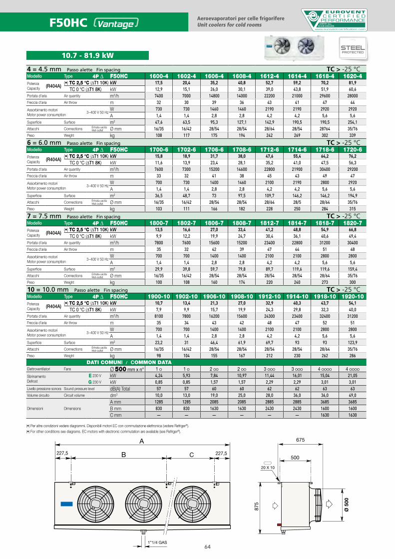
4 = 4.5 mm Passo alette Fin spacing TC > -25 °CModello Type 4P Δ F50HC 1600-4 1602-4 1606-4 1608-4 1612-4 1614-4 1618-4 1620-4PotenzaCapacity (R404A)
(•) TC 2,5 °C (ΔT1 10K) kW 17,5 20,4 35,2 40,8 52,7 59,2 70,2 81,9TC 0 °C (ΔT1 8K) kW 12,9 15,1 26,0 30,1 39,0 43,8 51,9 60,6
Portata d'aria Air quantity m3/h 7400 7000 14800 14000 22200 21000 29600 28000Freccia d'aria Air throw m 32 30 39 36 43 41 47 44
Assorbimento motoriMotor power consumption
3~400 V 50 HzW 730 730 1460 1460 2190 2190 2920 2920A 1,4 1,4 2,8 2,8 4,2 4,2 5,6 5,6
Superficie Surface m2 47,6 63,5 95,3 127,1 142,9 190,5 190,5 254,1Attacchi Connections Entrata-uscita
Inlet-outlet Ø mm 16/35 16/42 28/54 28/54 28/64 28/54 28764 35/76Peso Weight kg 108 117 175 194 242 269 302 339
6 = 6.0 mm Passo alette Fin spacing TC > -25 °CModello Type 4P Δ F50HC 1700-6 1702-6 1706-6 1708-6 1712-6 1714-6 1718-6 1720-6PotenzaCapacity (R404A)
(•) TC 2,5 °C (ΔT1 10K) kW 15,8 18,9 31,7 38,0 47,6 55,4 64,2 76,2TC 0 °C (ΔT1 8K) kW 11,6 13,9 23,4 28,1 35,2 41,0 47,5 56,3
Portata d'aria Air quantity m3/h 7600 7300 15200 14600 22800 21900 30400 29200Freccia d'aria Air throw m 33 32 41 38 45 43 49 47
Assorbimento motoriMotor power consumption
3~400 V 50 HzW 700 730 1400 1460 2100 2190 2800 2920A 1,4 1,4 2,8 2,8 4,2 4,2 5,6 5,6
Superficie Surface m2 36,5 48,7 73 97,5 109,7 146,2 146,2 194,9Attacchi Connections Entrata-uscita
Inlet-outlet Ø mm 16/35 16/42 28/54 28/54 28/64 28/5 28/64 35/76Peso Weight kg 103 111 166 182 228 250 284 315
7 = 7.5 mm Passo alette Fin spacing TC > -25 °CModello Type 4P Δ F50HC 1800-7 1802-7 1806-7 1808-7 1812-7 1814-7 1818-7 1820-7PotenzaCapacity (R404A)
(•) TC 2,5 °C (ΔT1 10K) kW 13,5 16,6 27,0 33,4 41,2 48,8 54,9 66,8TC 0 °C (ΔT1 8K) kW 9,9 12,2 19,9 24,7 30,4 36,1 40,6 49,4
Portata d'aria Air quantity m3/h 7800 7600 15600 15200 23400 22800 31200 30400Freccia d'aria Air throw m 35 32 42 39 47 44 51 48
Assorbimento motoriMotor power consumption
3~400 V 50 HzW 700 700 1400 1400 2100 2100 2800 2800A 1,4 1,4 2,8 2,8 4,2 4,2 5,6 5,6
Superficie Surface m2 29,9 39,8 59,7 79,8 89,7 119,6 119,6 159,4Attacchi Connections Entrata-uscita
Inlet-outlet Ø mm 16/35 16/42 28/54 28/54 28/54 28/54 28/64 35/76Peso Weight kg 100 108 160 174 220 240 273 300
10 = 10.0 mm Passo alette Fin spacing TC > -25 °CModello Type 4P Δ F50HC 1900-10 1902-10 1906-10 1908-10 1912-10 1914-10 1918-10 1920-10PotenzaCapacity (R404A)
(•) TC 2,5 °C (ΔT1 10K) kW 10,7 13,4 21,3 27,0 32,9 40,3 43,7 54,1TC 0 °C (ΔT1 8K) kW 7,9 9,9 15,7 19,9 24,3 29,8 32,3 40,0
Portata d'aria Air quantity m3/h 8100 7800 16200 15600 24300 23400 32400 31200Freccia d'aria Air throw m 35 34 43 42 48 47 52 51
Assorbimento motoriMotor power consumption
3~400 V 50 HzW 700 700 1400 1400 2100 2100 2800 2800A 1,4 1,4 2,8 2,8 4,2 4,2 5,6 5,6
Superficie Surface m2 23,2 31 46,4 61,9 69,7 93 93 123,9Attacchi Connections Entrata-uscita
Inlet-outlet Ø mm 16/35 16/42 28/54 28/54 28/54 28/54 28/64 35/76Peso Weight kg 98 104 155 167 212 230 262 286
DATI COMUNI / COMMON DATAElettroventilatori Fans Ø 500 mm x n° 1 O 1 O 2 OO 2 OO 3 OOO 3 OOO 4 OOOO 4 OOOO
SbrinamentoDefrost
E 230 V kW 4,24 5,93 7,84 10,97 11,44 16,01 15,04 21,05G 230 V kW 0,85 0,85 1,57 1,57 2,29 2,29 3,01 3,01
Livello pressione sonora Sound pressure level dB(A) Total 57 57 60 60 62 62 63 63Volume circuito Circuit volume dm3 10,0 13,0 19,0 25,0 28,0 36,0 36,0 49,0
Dimensioni Dimensions
A mm 1285 1285 2085 2085 2885 2885 3685 3685B mm 830 830 1630 1630 2430 2430 1600 1600C mm — — — — — — 1630 1630
Aeroevaporatori per celle frigorifereUnit coolers for cold rooms
10.7 - 81.9 kW
CERTIFY ALLDX AIR COOLERSF50HC
(•) Per altre condizioni vedere diagrammi. Disponibili motori EC con commutazione elettronica (vedere Refriger®).(•) For other conditions see diagrams. EC motors with electronic commutation are available (see Refriger®).
64
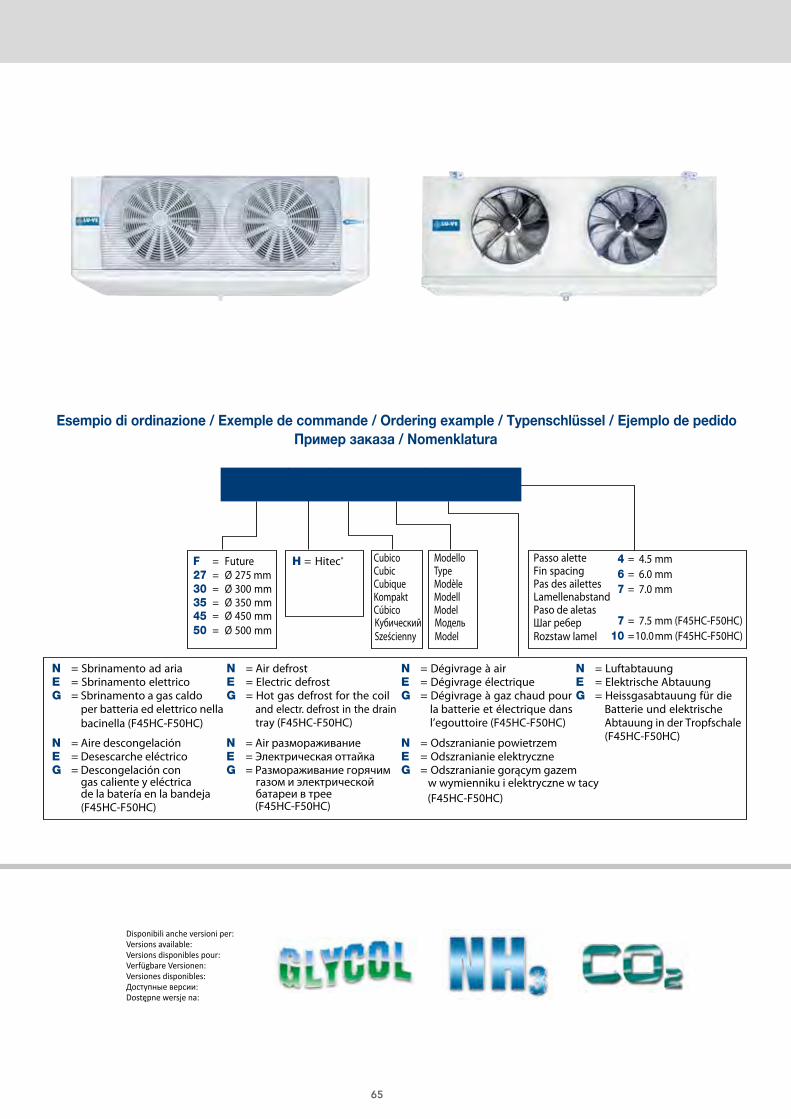
65
ModelloTypeModèleModell
Passo alette
Шаг реберRozstaw lamel
MодельModel
KубическийSześcienny
Fin spacingPas des ailettesLamellenabstandPaso de aletas
F50 H C 1602 E 4
F = Future27 = Ø 275 mm30 = Ø 300 mm35 = Ø 350 mm
= Ø 450 mm4550 = Ø 500 mm
H = Hitec® CubicoCubicCubique
ModelCúbicoKompakt
N = Sbrinamento ad ariaE = Sbrinamento elettricoG = Sbrinamento a gas caldo
per batteria ed elettrico nellabacinella (F45HC-F50HC)
N = Aire descongelaciónE = Desescarche eléctricoG = Descongelación con
gas caliente y eléctrica de la batería en la bandeja(F45HC-F50HC) (F45HC-F50HC)
(F45HC-F50HC)
N = Air размораживаниеE = Электрическая оттайкаG = Размораживание горячим
газом и электрической батареи в трее
N = Air defrost E = Electric defrostG = Hot gas defrost for the coil
and electr. defrost in the draintray (F45HC-F50HC)
N = Dégivrage à airE = Dégivrage électriqueG = Dégivrage à gaz chaud pour
la batterie et électrique dansl’egouttoire (F45HC-F50HC)
N = LuftabtauungE = Elektrische AbtauungG = Heissgasabtauung für die
Batterie und elektrischeAbtauung in der Tropfschale (F45HC-F50HC)
4 = 4.5 mm6 = 6.0 mm7 = 7.0 mm
7 = 7.5 mm (F45HC-F50HC)10 =10.0mm (F45HC-F50HC)
N = Odszranianie powietrzemE = Odszranianie elektryczneG = Odszranianie gorącym gazem
w wymienniku i elektryczne w tacy
Passo aletteFin spacingPas des ailettesLamellenabstandPaso de aletasШаг лameлeй Podziałka lamel
4 = 4,5 mm6 = 6,0 mm7 = 7,5 mm
10 = 10,0 mm12 = 12,0 mm
CS = Compact SurfaceLS = Large Surface
H = Hitec®
Ventilatori (Altezza moduli)Fans (Height modules)Ventilateurs (Hauteur modules)Ventilatoren (Höhe module)VeВентиляторы
ntiladores (Altura modulos)
(Высота единиц)
Wentilatory (Wysokość modułów)
45 = Ø 450 mm (550 mm)
50 = Ø 500 mm (770 mm)
62 = Ø 630 mm (770 mm)
71 = Ø 710 mm (990 mm)
80 = Ø 800 mm (1250 mm)
ModelloType ModèleModellModeloМодельModel
CS 62 H 2214 E 6
N = Sbrinamento ad ariaE = Sbrinamento elettricoSB = Sbrinamento ad acquaG = Sbrinamento a gas caldo per
batteria ed elettrico nella bacinellaGB= Sbrinamento a gas caldo per
batteria e bacinella
N = Воздушная разморозкаE = Электрическая разморозкаSB = Водяная разморозкаG = Разморозка горячим газом для
теплообменника и электрическая разморозка для дренажного контейнера= разморозка горячим газом и для теплообменника и для дренажного контейнера
GB
N = Odszranianie powietrzemE = Odszranianie elektryczneSB = Odszranianie wodąG = Odszranianie gorącym gazem w
wymienniku i elektryczne w tacyGB= Odszranianie gorącym gazem w
wymienniku i tacy
N = Air defrostE = Electric defrostSB = Water spray defrostG = Hot gas defrost for the coil and
electr. defrost in the drain trayGB= Hot gas defrost for
both coil and drain tray
N = Dégivrage à airE = Dégivrage électriqueSB = Dégivrage à eauG = Dégivrage à gaz chaud
pour la batterie etélectrique dans l’egouttoire
GB= Dégivrage à gazchaud pour la batterieet l’egouttoire
N = LuftabtauungE = Elektrische AbtauungSB = WasserabtauungG = Heissgasabtauung für die
Batterie und elektrische Abtauung in der Tropfschale
GB= Heissgasabtauung fürdie Batterie und Tropf-schale
N = Desescarche por aireE = Desescarche eléctricoSB = Desescarche por aguaG = Desescarche por gas
caliente en bateria yeléctrico en bandeja
GB= Desescarche por gascaliente en bateria ybandeja
Metodo di sceltadell’aeroevaporatore
Unit cooler model selection
Méthode de sélection de l’évaporateur
Auswahlmethoden für Hochleistungsluftkühler
Метод выбора
Dobór chłodnicy powietrza
Método de selección de evaporador
Scelta rapida Quick selection Sélection rapide Schnellauswahl Selección rápida Мгновенный подбор Szybki dobór
TC = 0°C UR = 85% ∆T1 = 7 K CT = 53 kWFreccia d’aria Air throw Projection de l’aire Wurfweite Dardo de aire Воздушный поток Zasięg strumienia powietrza
Шаг ламелей Podziałka lamel
= 48 mFluido refrigerante Refrigerant fluid Fluide réfrigérant Kältemittel Refrigerante Хладагент Czynnik chłodniczy = R404APasso alette Fin spacing Pas des ailettes Lamellenabstand Paso aletas = 6,0 mm
CT x 1/FC = 53 x 1/0,65 = 81,5 kWSelezione / Selection / Sélection / Typenauswahl / Selección / Bыбор / Wybór = CS62H2214E6 Potenza / Rating / Puissance / Leistung / Potencia / Bласть / Moc = ∆T1 10K = 82,3 kW (Catalogo / Catalogue / Catalogue / Katalog
Catálogo / Kаталог/ Katalog)∆T1 = 81,5/82,3 x 7 = 6,9 KTE = TC - ∆T1 = 0 - 6,9 = - 6,9 °C
socisäb sotaDnetaD-sisaBesab ed seénnoDatad cisaBesab id itaD
Nota
Внимание Uwagi
Un'analoga potenza è ot-tenibile con differente:• Modello• Ø x n° ventilatori• Portata d’aria• Freccia d’aria• Superficie• Sbrinamento (E)• Dimensioni
NoteA similar capacity is obtai-nable with different:• Type• Ø x n° fans• Air quantity• Air throw• Surface• Defrost (E)• Dimensions
•
•
Mодель
Одинаковая мощность получается различными:
• Ø x n° вентиляторы• Воздушный факел
• Podobną wydajność można uzyskać poprzez zmianę:
• Объем воздуха• Поверхность• Разморозка (E)• Размеры
• Przepływ powietrza• Zasięgu strumienia powietrza• Średnicy i liczby wentylatorów
• Powierzchnia• Rozmrażanie (E)• Wymiary
NoteOn peut obtenir une puis-sance identique avec diffé-rent:• Modèle• Ø x n° quantité de mo-
teurs• Débits d'air• Portées d'air• Surfaces• Dégivrages (E)• Dimensions
AnmerkungEine analoge Leistung isterreichbar mit Änderungvon:• Modell• Ø x n° Motorenanzahl• Luftdurchsatz• Wurfweite• Fläche• Abtauung (E)• Abmessungen
NoteUna potencia similar seobtiene con diferente:• Modelo• Ø x n° motores• Caudal de aire• Dardo de aire• Superficie• Desescarche (E)• Dimensiones
Основные данные Dane podstawowe
Esempio di ordinazione / Exemple de commande / Ordering example / Typenschlüssel / Ejemplo de pedidoПример заказа / Nomenklatura
Disponibili anche versioni per:Versions available:Versions disponibles pour:Verfügbare Versionen:Versiones disponibles:Доступные версии:Dostępne wersje na:
CERTIFY ALLDX AIR COOLERS
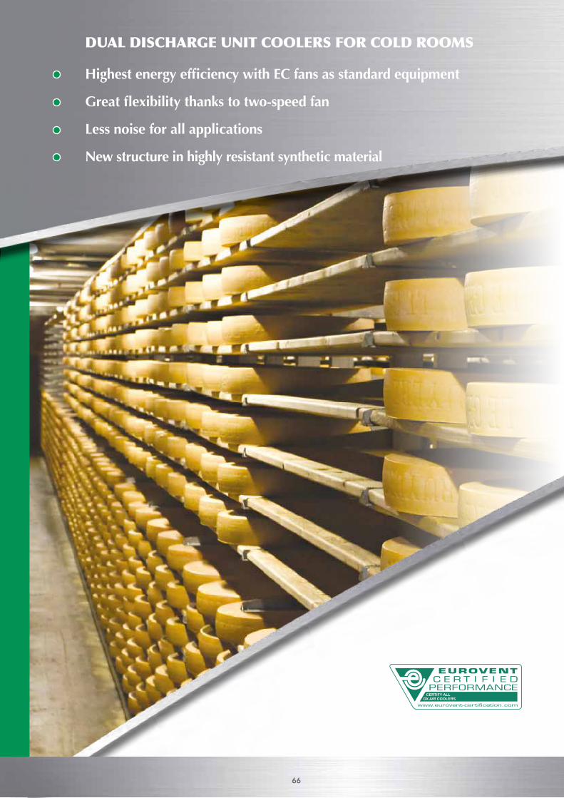
DUAL DISCHARGE UNIT COOLERS FOR COLD ROOMS
Highest energy efficiency with EC fans as standard equipment
Great flexibility thanks to two-speed fan
Less noise for all applications
New structure in highly resistant synthetic material
66
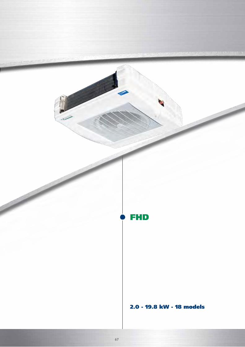
2.0 - 19.8 kW - 18 models
FHD
DUAL DISCHARGE UNIT COOLERS FOR COLD ROOMS
Highest energy efficiency with EC fans as standard equipment
Great flexibility thanks to two-speed fan
Less noise for all applications
New structure in highly resistant synthetic material
67
SMARTPATENTED
DUALDISCHARGE
STSSAFETUBES
SYSTEM
SMARTPATENTED
JETSTREAMER
J-O-MJET-O-MATIC
BENEFIT®STEELPROTECTED
DUALDISCHARGE
STSSAFETUBES
SYSTEM
SMARTPATENTED
JETSTREAMER
J-O-MJET-O-MATIC
BENEFIT®STEELPROTECTED
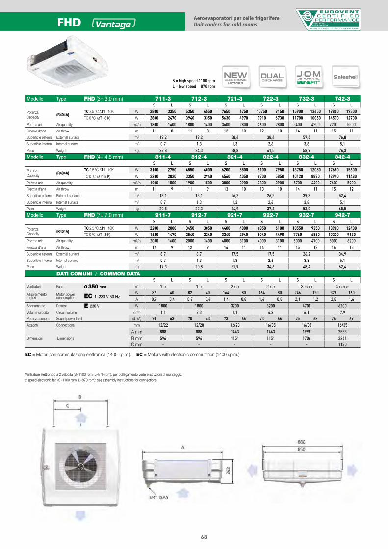
S = high speed 1100 rpmL = low speed 870 rpm
Aeroevaporatori per celle frigorifereUnit coolers for cold rooms CERTIFY ALL
DX AIR COOLERSFHD
68
Modello Type FHD (3= 3.0 mm) 711-3 712-3 721-3 722-3 732-3 742-3S L S L S L S L S L S L
PotenzaCapacity (R404A)
TC 2,5 °C ΔT1 10K W 3800 3350 5350 4550 7650 6750 10750 9150 15900 13650 19800 17300TC 0 °C (ΔT1 8 K) W 2800 2470 3940 3350 5630 4970 7910 6730 11700 10050 14570 12730
Portata aria Air quantity m3/h 1800 1400 1800 1400 3600 2800 3600 2800 5400 4200 7200 5500Freccia d'aria Air throw m 11 8 11 8 12 10 12 10 14 11 15 11Superficie esterna External surface m2 19,2 19,2 38,4 38,4 57,6 76,8Superficie interna Internal surface m2 0,7 1,3 1,3 2,6 3,8 5,1Peso Weight kg 22,8 24,3 38,8 41,5 58,9 76,3Modello Type FHD (4= 4.5 mm) 811-4 812-4 821-4 822-4 832-4 842-4
S L S L S L S L S L S L
PotenzaCapacity (R404A)
TC 2,5 °C ΔT1 10K W 3100 2750 4550 4000 6200 5500 9100 7950 13750 12050 17650 15600TC 0 °C (ΔT1 8 K) W 2280 2020 3350 2940 4560 4050 6700 5850 10120 8870 12990 11480
Portata aria Air quantity m3/h 1900 1500 1900 1500 3800 2900 3800 2900 5700 4400 7600 5900Freccia d'aria Air throw m 11 9 11 9 13 10 13 10 14 11 15 12Superficie esterna External surface m2 13,1 13,1 26,2 26,2 39,3 52,4Superficie interna Internal surface m2 0,7 1,3 1,3 2,6 3,8 5,1Peso Weight kg 20,8 22,3 34,9 37,6 53,0 68,5Modello Type FHD (7= 7.0 mm) 911-7 912-7 921-7 922-7 932-7 942-7
S L S L S L S L S L S L
PotenzaCapacity (R404A)
TC 2,5 °C ΔT1 10K W 2200 2000 3450 3050 4400 4000 6850 6100 10550 9350 13900 12400TC 0 °C (ΔT1 8 K) W 1620 1470 2540 2240 3240 2940 5040 4490 7760 6880 10230 9130
Portata aria Air quantity m3/h 2000 1600 2000 1600 4000 3100 4000 3100 6000 4700 8000 6200Freccia d'aria Air throw m 12 9 12 9 14 11 14 11 15 12 16 13Superficie esterna External surface m2 8,7 8,7 17,5 17,5 26,2 34,9Superficie interna Internal surface m2 0,7 1,3 1,3 2,6 3,8 5,1Peso Weight kg 19,3 20,8 31,9 34,6 48,4 62,4
DATI COMUNI / COMMON DATAS L S L S L S L S L S L
Ventilatori Fans Ø 350 mm n° 1 O 1 O 2 OO 2 OO 3 OOO 4 OOOO
Assorbimento motori
Motor power consumption EC 1~230 V 50 Hz
W 82 40 82 40 164 80 164 80 246 120 328 160A 0,7 0,4 0,7 0,4 1,4 0,8 1,4 0,8 2,1 1,2 2,8 1,6
Sbrinamento Defrost E 230 V W 1800 1800 3200 3200 4700 6200Volume circuito Circuit volume dm3 1,1 2,3 2,1 4,2 6,1 7,9Potenza sonora Sound power level db (A) 70 63 70 63 73 66 73 66 75 68 76 69Attacchi Connections mm 12/22 12/28 12/28 16/35 16/35 16/35
Dimensioni Dimensions
A mm 888 888 1443 1443 1998 2553B mm 596 596 1151 1151 1706 2261C mm - - - - - 1130
Ventilatore elettronico a 2 velocità (S=1100 rpm, L=870 rpm), per collegamento vedere istruzioni di montaggio.2 speed electronic fan (S=1100 rpm, L=870 rpm): see assembly instructions for connections.
T.C.TURBOCOOLER
SUPERSILENT
EFFICIENT
NEWELECTRONIC
MOTORS
GLYCOL NH3 CO2
EC = Motori con commutazione elettronica (1400 r.p.m.). EC = Motors with electronic commutation (1400 r.p.m.).

69
Passo aletteFin spacingPas des ailettesLamellenabstandPaso de aletasШаг лameлeй Podziałka lamel
4 = 4,5 mm6 = 6,0 mm7 = 7,5 mm
10 = 10,0 mm12 = 12,0 mm
CS = Compact SurfaceLS = Large Surface
H = Hitec®
Ventilatori (Altezza moduli)Fans (Height modules)Ventilateurs (Hauteur modules)Ventilatoren (Höhe module)VeВентиляторы
ntiladores (Altura modulos)
(Высота единиц)
Wentilatory (Wysokość modułów)
45 = Ø 450 mm (550 mm)
50 = Ø 500 mm (770 mm)
62 = Ø 630 mm (770 mm)
71 = Ø 710 mm (990 mm)
80 = Ø 800 mm (1250 mm)
ModelloType ModèleModellModeloМодельModel
CS 62 H 2214 E 6
N = Sbrinamento ad ariaE = Sbrinamento elettricoSB = Sbrinamento ad acquaG = Sbrinamento a gas caldo per
batteria ed elettrico nella bacinellaGB= Sbrinamento a gas caldo per
batteria e bacinella
N = Воздушная разморозкаE = Электрическая разморозкаSB = Водяная разморозкаG = Разморозка горячим газом для
теплообменника и электрическая разморозка для дренажного контейнера= разморозка горячим газом и для теплообменника и для дренажного контейнера
GB
N = Odszranianie powietrzemE = Odszranianie elektryczneSB = Odszranianie wodąG = Odszranianie gorącym gazem w
wymienniku i elektryczne w tacyGB= Odszranianie gorącym gazem w
wymienniku i tacy
N = Air defrostE = Electric defrostSB = Water spray defrostG = Hot gas defrost for the coil and
electr. defrost in the drain trayGB= Hot gas defrost for
both coil and drain tray
N = Dégivrage à airE = Dégivrage électriqueSB = Dégivrage à eauG = Dégivrage à gaz chaud
pour la batterie etélectrique dans l’egouttoire
GB= Dégivrage à gazchaud pour la batterieet l’egouttoire
N = LuftabtauungE = Elektrische AbtauungSB = WasserabtauungG = Heissgasabtauung für die
Batterie und elektrische Abtauung in der Tropfschale
GB= Heissgasabtauung fürdie Batterie und Tropf-schale
N = Desescarche por aireE = Desescarche eléctricoSB = Desescarche por aguaG = Desescarche por gas
caliente en bateria yeléctrico en bandeja
GB= Desescarche por gascaliente en bateria ybandeja
Metodo di sceltadell’aeroevaporatore
Unit cooler model selection
Méthode de sélection de l’évaporateur
Auswahlmethoden für Hochleistungsluftkühler
Метод выбора
Dobór chłodnicy powietrza
Método de selección de evaporador
Scelta rapida Quick selection Sélection rapide Schnellauswahl Selección rápida Мгновенный подбор Szybki dobór
TC = 0°C UR = 85% ∆T1 = 7 K CT = 53 kWFreccia d’aria Air throw Projection de l’aire Wurfweite Dardo de aire Воздушный поток Zasięg strumienia powietrza
Шаг ламелей Podziałka lamel
= 48 mFluido refrigerante Refrigerant fluid Fluide réfrigérant Kältemittel Refrigerante Хладагент Czynnik chłodniczy = R404APasso alette Fin spacing Pas des ailettes Lamellenabstand Paso aletas = 6,0 mm
CT x 1/FC = 53 x 1/0,65 = 81,5 kWSelezione / Selection / Sélection / Typenauswahl / Selección / Bыбор / Wybór = CS62H2214E6 Potenza / Rating / Puissance / Leistung / Potencia / Bласть / Moc = ∆T1 10K = 82,3 kW (Catalogo / Catalogue / Catalogue / Katalog
Catálogo / Kаталог/ Katalog)∆T1 = 81,5/82,3 x 7 = 6,9 KTE = TC - ∆T1 = 0 - 6,9 = - 6,9 °C
socisäb sotaDnetaD-sisaBesab ed seénnoDatad cisaBesab id itaD
Nota
Внимание Uwagi
Un'analoga potenza è ot-tenibile con differente:• Modello• Ø x n° ventilatori• Portata d’aria• Freccia d’aria• Superficie• Sbrinamento (E)• Dimensioni
NoteA similar capacity is obtai-nable with different:• Type• Ø x n° fans• Air quantity• Air throw• Surface• Defrost (E)• Dimensions
•
•
Mодель
Одинаковая мощность получается различными:
• Ø x n° вентиляторы• Воздушный факел
• Podobną wydajność można uzyskać poprzez zmianę:
• Объем воздуха• Поверхность• Разморозка (E)• Размеры
• Przepływ powietrza• Zasięgu strumienia powietrza• Średnicy i liczby wentylatorów
• Powierzchnia• Rozmrażanie (E)• Wymiary
NoteOn peut obtenir une puis-sance identique avec diffé-rent:• Modèle• Ø x n° quantité de mo-
teurs• Débits d'air• Portées d'air• Surfaces• Dégivrages (E)• Dimensions
AnmerkungEine analoge Leistung isterreichbar mit Änderungvon:• Modell• Ø x n° Motorenanzahl• Luftdurchsatz• Wurfweite• Fläche• Abtauung (E)• Abmessungen
NoteUna potencia similar seobtiene con diferente:• Modelo• Ø x n° motores• Caudal de aire• Dardo de aire• Superficie• Desescarche (E)• Dimensiones
Основные данные Dane podstawowe
Esempio di ordinazione / Exemple de commande / Ordering example / Typenschlüssel / Ejemplo de pedidoПример заказа / Nomenklatura
FHD 732 E 3
F = Future
H =
D = DoDual discharge
Zweiseitig ausblasend
ModelloTypeModèleModell
E = S brinamento elettricoElectric defrostDégivrage électriqueElektrische Abtauung
N = Sbrinamento ad ariaAir defrostDégivrage à airLuftabtauung
Passo aletteFin spacingPas des ailettesLamellanabstandPaso de aletasШаг реберRozstaw lamel
Desescarche eléctricoЭлектрическая оттайкаOdszaranianie elektryczne
Air descongelaciónРазмораживание воздухаRozmrażanie powietrzem
ModeloMодельModel
3 = 3.0 mm4 = 4.5 mm7 = 7.0 mm
Двойной разрядаPodwójny wyrzut powietrza
Hitec®
Disponibili anche versioni per:Versions available:Versions disponibles pour:Verfügbare Versionen:Versiones disponibles:Доступные версии:Dostępne wersje na:
CERTIFY ALLDX AIR COOLERS
ANGLED UNIT COOLERS FOR COLD ROOMS
Protective steel casing
High energy efficiency
70
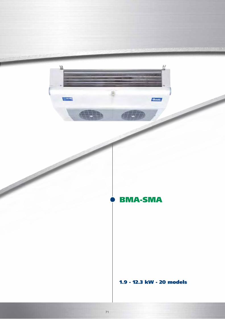
1.9 - 12.3 kW - 20 models
BMA-SMA
ANGLED UNIT COOLERS FOR COLD ROOMS
Protective steel casing
High energy efficiency
71
DUALDISCHARGE
STSSAFETUBES
SYSTEM
SMARTPATENTED
JETSTREAMER
J-O-MJET-O-MATIC
BENEFIT®STEELPROTECTED
DUALDISCHARGE
STSSAFETUBES
SYSTEM
SMARTPATENTED
JETSTREAMER
J-O-MJET-O-MATIC
BENEFIT®STEELPROTECTED
BMA - SMA Aeroevaporatori per celle frigorifereUnit coolers for cold rooms
CERTIFY ALLDX AIR COOLERS
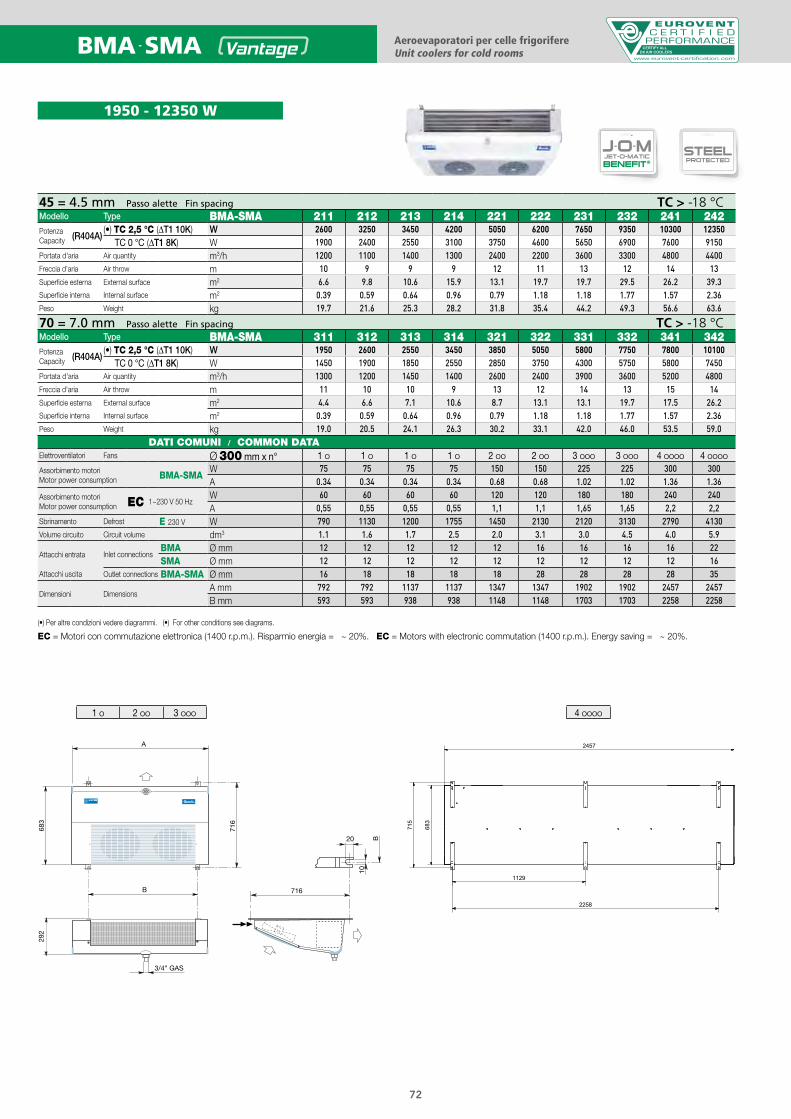
1950 - 12350 W
45 = 4.5 mm Passo alette Fin spacing TC > -18 °CModello Type BMA-SMA 211 212 213 214 221 222 231 232 241 242PotenzaCapacity (R404A)
(•) TC 2,5 °C (ΔT1 10K) W 2600 3250 3450 4200 5050 6200 7650 9350 10300 12350TC 0 °C (ΔT1 8K) W 1900 2400 2550 3100 3750 4600 5650 6900 7600 9150
Portata d'aria Air quantity m3/h 1200 1100 1400 1300 2400 2200 3600 3300 4800 4400Freccia d'aria Air throw m 10 9 9 9 12 11 13 12 14 13Superficie esterna External surface m2 6.6 9.8 10.6 15.9 13.1 19.7 19.7 29.5 26.2 39.3Superficie interna Internal surface m2 0.39 0.59 0.64 0.96 0.79 1.18 1.18 1.77 1.57 2.36Peso Weight kg 19.7 21.6 25.3 28.2 31.8 35.4 44.2 49.3 56.6 63.6
70 = 7.0 mm Passo alette Fin spacing TC > -18 °CModello Type BMA-SMA 311 312 313 314 321 322 331 332 341 342PotenzaCapacity (R404A)
(•) TC 2,5 °C (ΔT1 10K) W 1950 2600 2550 3450 3850 5050 5800 7750 7800 10100TC 0 °C (ΔT1 8K) W 1450 1900 1850 2550 2850 3750 4300 5750 5800 7450
Portata d'aria Air quantity m3/h 1300 1200 1450 1400 2600 2400 3900 3600 5200 4800Freccia d'aria Air throw m 11 10 10 9 13 12 14 13 15 14Superficie esterna External surface m2 4.4 6.6 7.1 10.6 8.7 13.1 13.1 19.7 17.5 26.2Superficie interna Internal surface m2 0.39 0.59 0.64 0.96 0.79 1.18 1.18 1.77 1.57 2.36Peso Weight kg 19.0 20.5 24.1 26.3 30.2 33.1 42.0 46.0 53.5 59.0
DATI COMUNI / COMMON DATAElettroventilatori Fans Ø 300 mm x n° 1 O 1 O 1 O 1 O 2 OO 2 OO 3 OOO 3 OOO 4 OOOO 4 OOOO
Assorbimento motoriMotor power consumption BMA-SMA
W 75 75 75 75 150 150 225 225 300 300A 0.34 0.34 0.34 0.34 0.68 0.68 1.02 1.02 1.36 1.36
Assorbimento motoriMotor power consumption EC 1~230 V 50 Hz
W 60 60 60 60 120 120 180 180 240 240A 0,55 0,55 0,55 0,55 1,1 1,1 1,65 1,65 2,2 2,2
Sbrinamento Defrost E 230 V W 790 1130 1200 1755 1450 2130 2120 3130 2790 4130Volume circuito Circuit volume dm3 1.1 1.6 1.7 2.5 2.0 3.1 3.0 4.5 4.0 5.9
Attacchi entrata Inlet connectionsBMA Ø mm 12 12 12 12 12 16 16 16 16 22SMA Ø mm 12 12 12 12 12 12 12 12 12 16
Attacchi uscita Outlet connections BMA-SMA Ø mm 16 18 18 18 18 28 28 28 28 35
Dimensioni DimensionsA mm 792 792 1137 1137 1347 1347 1902 1902 2457 2457B mm 593 593 938 938 1148 1148 1703 1703 2258 2258
(•) Per altre condizioni vedere diagrammi. (•) For other conditions see diagrams.
EC = Motori con commutazione elettronica (1400 r.p.m.). Risparmio energia = ~ 20%. EC = Motors with electronic commutation (1400 r.p.m.). Energy saving = ~ 20%.
72
4 OOOO1 O 2 OO 3 OOO
Passo aletteFin spacingPas des ailettesLamellenabstandPaso de aletasШаг лameлeй Podziałka lamel
4 = 4,5 mm6 = 6,0 mm7 = 7,5 mm
10 = 10,0 mm12 = 12,0 mm
CS = Compact SurfaceLS = Large Surface
H = Hitec®
Ventilatori (Altezza moduli)Fans (Height modules)Ventilateurs (Hauteur modules)Ventilatoren (Höhe module)VeВентиляторы
ntiladores (Altura modulos)
(Высота единиц)
Wentilatory (Wysokość modułów)
45 = Ø 450 mm (550 mm)
50 = Ø 500 mm (770 mm)
62 = Ø 630 mm (770 mm)
71 = Ø 710 mm (990 mm)
80 = Ø 800 mm (1250 mm)
ModelloType ModèleModellModeloМодельModel
CS 62 H 2214 E 6
N = Sbrinamento ad ariaE = Sbrinamento elettricoSB = Sbrinamento ad acquaG = Sbrinamento a gas caldo per
batteria ed elettrico nella bacinellaGB= Sbrinamento a gas caldo per
batteria e bacinella
N = Воздушная разморозкаE = Электрическая разморозкаSB = Водяная разморозкаG = Разморозка горячим газом для
теплообменника и электрическая разморозка для дренажного контейнера= разморозка горячим газом и для теплообменника и для дренажного контейнера
GB
N = Odszranianie powietrzemE = Odszranianie elektryczneSB = Odszranianie wodąG = Odszranianie gorącym gazem w
wymienniku i elektryczne w tacyGB= Odszranianie gorącym gazem w
wymienniku i tacy
N = Air defrostE = Electric defrostSB = Water spray defrostG = Hot gas defrost for the coil and
electr. defrost in the drain trayGB= Hot gas defrost for
both coil and drain tray
N = Dégivrage à airE = Dégivrage électriqueSB = Dégivrage à eauG = Dégivrage à gaz chaud
pour la batterie etélectrique dans l’egouttoire
GB= Dégivrage à gazchaud pour la batterieet l’egouttoire
N = LuftabtauungE = Elektrische AbtauungSB = WasserabtauungG = Heissgasabtauung für die
Batterie und elektrische Abtauung in der Tropfschale
GB= Heissgasabtauung fürdie Batterie und Tropf-schale
N = Desescarche por aireE = Desescarche eléctricoSB = Desescarche por aguaG = Desescarche por gas
caliente en bateria yeléctrico en bandeja
GB= Desescarche por gascaliente en bateria ybandeja
Metodo di sceltadell’aeroevaporatore
Unit cooler model selection
Méthode de sélection de l’évaporateur
Auswahlmethoden für Hochleistungsluftkühler
Метод выбора
Dobór chłodnicy powietrza
Método de selección de evaporador
Scelta rapida Quick selection Sélection rapide Schnellauswahl Selección rápida Мгновенный подбор Szybki dobór
TC = 0°C UR = 85% ∆T1 = 7 K CT = 53 kWFreccia d’aria Air throw Projection de l’aire Wurfweite Dardo de aire Воздушный поток Zasięg strumienia powietrza
Шаг ламелей Podziałka lamel
= 48 mFluido refrigerante Refrigerant fluid Fluide réfrigérant Kältemittel Refrigerante Хладагент Czynnik chłodniczy = R404APasso alette Fin spacing Pas des ailettes Lamellenabstand Paso aletas = 6,0 mm
CT x 1/FC = 53 x 1/0,65 = 81,5 kWSelezione / Selection / Sélection / Typenauswahl / Selección / Bыбор / Wybór = CS62H2214E6 Potenza / Rating / Puissance / Leistung / Potencia / Bласть / Moc = ∆T1 10K = 82,3 kW (Catalogo / Catalogue / Catalogue / Katalog
Catálogo / Kаталог/ Katalog)∆T1 = 81,5/82,3 x 7 = 6,9 KTE = TC - ∆T1 = 0 - 6,9 = - 6,9 °C
socisäb sotaDnetaD-sisaBesab ed seénnoDatad cisaBesab id itaD
Nota
Внимание Uwagi
Un'analoga potenza è ot-tenibile con differente:• Modello• Ø x n° ventilatori• Portata d’aria• Freccia d’aria• Superficie• Sbrinamento (E)• Dimensioni
NoteA similar capacity is obtai-nable with different:• Type• Ø x n° fans• Air quantity• Air throw• Surface• Defrost (E)• Dimensions
•
•
Mодель
Одинаковая мощность получается различными:
• Ø x n° вентиляторы• Воздушный факел
• Podobną wydajność można uzyskać poprzez zmianę:
• Объем воздуха• Поверхность• Разморозка (E)• Размеры
• Przepływ powietrza• Zasięgu strumienia powietrza• Średnicy i liczby wentylatorów
• Powierzchnia• Rozmrażanie (E)• Wymiary
NoteOn peut obtenir une puis-sance identique avec diffé-rent:• Modèle• Ø x n° quantité de mo-
teurs• Débits d'air• Portées d'air• Surfaces• Dégivrages (E)• Dimensions
AnmerkungEine analoge Leistung isterreichbar mit Änderungvon:• Modell• Ø x n° Motorenanzahl• Luftdurchsatz• Wurfweite• Fläche• Abtauung (E)• Abmessungen
NoteUna potencia similar seobtiene con diferente:• Modelo• Ø x n° motores• Caudal de aire• Dardo de aire• Superficie• Desescarche (E)• Dimensiones
Основные данные Dane podstawowe
Esempio di ordinazione / Exemple de commande / Ordering example / Typenschlüssel / Ejemplo de pedidoПример заказа / Nomenklatura
BMA 222 E 45
B =
S = Super
M = Carenatura metallica Metal casingCarosserie metallique Metallgehäuse
A = Angolare AngledAngulaire Winkling
ModelloTypeModèleModellModeloMодельModel
Paso de aletas Шаг реберRozstaw lamel
N = Sbrinamento ad ariaAir defrostDégivrage à airLuftabtauung
E = Sbrinamento elettricoElectric defrostDégivrage électriqueElektrische Abtauung
Passo alette Fin spacingPas des ailettes Lamellenabstand
45 = 4.5 mm
70 = 7.0 mm
Angular УгловойKątowy
Carenado de metalМеталлический корпусMetalowa obudowa
Air descongelaciónРазмораживание воздухаRozmrażanie powietrzem
Desescarche eléctricoЭлектрическая оттайкаOdszaranianie elektryczne
Disponibili anche versioni per:Versions available:Versions disponibles pour:Verfügbare Versionen:Versiones disponibles:Доступные версии:Dostępne wersje na:
73
CERTIFY ALLDX AIR COOLERS
74
ANGLED UNIT COOLERS FOR COLD ROOMS
Safeshell casingDRYAND
SPRAY
WATERSPRAYSYSTEM
S.G.B.S. LESS
Safeshell
ENERGYSAVING
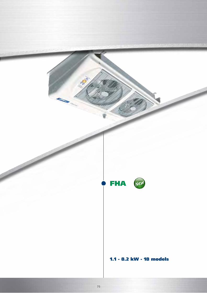
1.1 - 8.2 kW - 18 models
FHA
75
ANGLED UNIT COOLERS FOR COLD ROOMS
Safeshell casing
DUALDISCHARGE
STSSAFETUBES
SYSTEM
SMARTPATENTED
JETSTREAMER
J-O-MJET-O-MATIC
BENEFIT®STEELPROTECTED
DRYAND
SPRAY
WATERSPRAY
SYSTEM
SMARTPATENTED
S.G.B.S. LESS
Safeshell
ENERGYSAVING
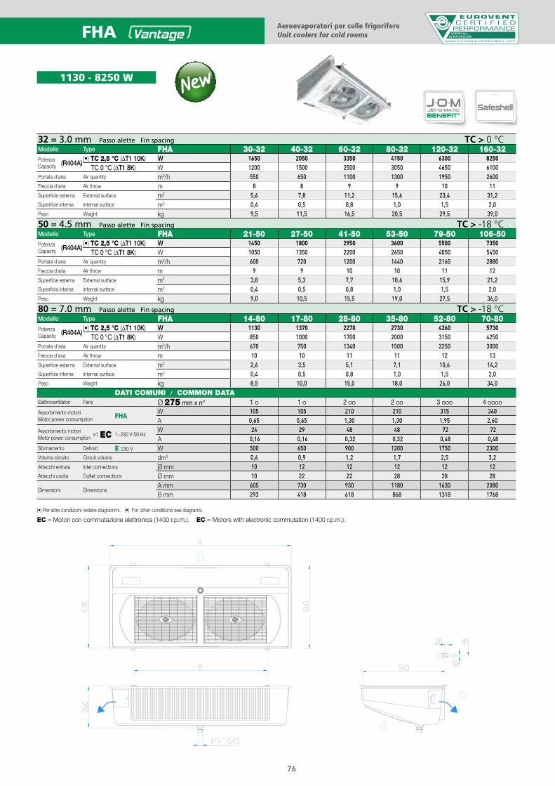
1130 - 8250 W
Aeroevaporatori per celle frigorifereUnit coolers for cold rooms CERTIFY ALL
DX AIR COOLERSFHA
32 = 3.0 mm Passo alette Fin spacing TC > 0 °CModello Type FHA 30-32 40-32 60-32 80-32 120-32 160-32PotenzaCapacity (R404A)
(•) TC 2,5 °C (ΔT1 10K) W 1650 2050 3350 4150 6300 8250TC 0 °C (ΔT1 8K) W 1200 1500 2500 3050 4650 6100
Portata d'aria Air quantity m3/h 550 650 1100 1300 1950 2600Freccia d'aria Air throw m 8 8 9 9 10 11Superficie esterna External surface m2 5,6 7,8 11,2 15,6 23,4 31,2Superficie interna Internal surface m2 0,4 0,5 0,8 1,0 1,5 2,0Peso Weight kg 9,5 11,5 16,5 20,5 29,5 39,0
50 = 4.5 mm Passo alette Fin spacing TC > -18 °CModello Type FHA 21-50 27-50 41-50 53-50 79-50 106-50PotenzaCapacity (R404A)
(•) TC 2,5 °C (ΔT1 10K) W 1450 1800 2950 3600 5500 7350TC 0 °C (ΔT1 8K) W 1050 1350 2200 2650 4050 5450
Portata d'aria Air quantity m3/h 600 720 1200 1440 2160 2880Freccia d'aria Air throw m 9 9 10 10 11 12Superficie esterna External surface m2 3,8 5,3 7,7 10,6 15,9 21,2Superficie interna Internal surface m2 0,4 0,5 0,8 1,0 1,5 2,0Peso Weight kg 9,0 10,5 15,5 19,0 27,5 36,0
80 = 7.0 mm Passo alette Fin spacing TC > -18 °CModello Type FHA 14-80 17-80 28-80 35-80 52-80 70-80PotenzaCapacity (R404A)
(•) TC 2,5 °C (ΔT1 10K) W 1130 1370 2270 2730 4260 5730TC 0 °C (ΔT1 8K) W 850 1000 1700 2000 3150 4250
Portata d'aria Air quantity m3/h 670 750 1340 1500 2250 3000Freccia d'aria Air throw m 10 10 11 11 12 13Superficie esterna External surface m2 2,6 3,5 5,1 7,1 10,6 14,2Superficie interna Internal surface m2 0,4 0,5 0,8 1,0 1,5 2,0Peso Weight kg 8,5 10,0 15,0 18,0 26,0 34,0
DATI COMUNI / COMMON DATAElettroventilatori Fans Ø 275 mm x n° 1 O 1 O 2 OO 2 OO 3 OOO 4 OOOO
Assorbimento motoriMotor power consumption FHA
W 105 105 210 210 315 340A 0,65 0,65 1,30 1,30 1,95 2,60
Assorbimento motori x1
Motor power consumption EC 1~230 V 50 HzW 24 29 48 48 72 72A 0,16 0,16 0,32 0,32 0,48 0,48
Sbrinamento Defrost E 230 V W 500 650 900 1200 1750 2300Volume circuito Circuit volume dm3 0,6 0,9 1,2 1,7 2,5 3,2Attacchi entrata Inlet connections Ø mm 10 12 12 12 12 12Attacchi uscita Outlet connections Ø mm 10 22 22 28 28 28
Dimensioni DimensionsA mm 605 730 930 1180 1630 2080B mm 293 418 618 868 1318 1768
(•) Per altre condizioni vedere diagrammi. (•) For other conditions see diagrams.
EC = Motori con commutazione elettronica (1400 r.p.m.). EC = Motors with electronic commutation (1400 r.p.m.).
76
Passo aletteFin spacingPas des ailettesLamellenabstandPaso de aletasШаг лameлeй Podziałka lamel
4 = 4,5 mm6 = 6,0 mm7 = 7,5 mm
10 = 10,0 mm12 = 12,0 mm
CS = Compact SurfaceLS = Large Surface
H = Hitec®
Ventilatori (Altezza moduli)Fans (Height modules)Ventilateurs (Hauteur modules)Ventilatoren (Höhe module)VeВентиляторы
ntiladores (Altura modulos)
(Высота единиц)
Wentilatory (Wysokość modułów)
45 = Ø 450 mm (550 mm)
50 = Ø 500 mm (770 mm)
62 = Ø 630 mm (770 mm)
71 = Ø 710 mm (990 mm)
80 = Ø 800 mm (1250 mm)
ModelloType ModèleModellModeloМодельModel
CS 62 H 2214 E 6
N = Sbrinamento ad ariaE = Sbrinamento elettricoSB = Sbrinamento ad acquaG = Sbrinamento a gas caldo per
batteria ed elettrico nella bacinellaGB= Sbrinamento a gas caldo per
batteria e bacinella
N = Воздушная разморозкаE = Электрическая разморозкаSB = Водяная разморозкаG = Разморозка горячим газом для
теплообменника и электрическая разморозка для дренажного контейнера= разморозка горячим газом и для теплообменника и для дренажного контейнера
GB
N = Odszranianie powietrzemE = Odszranianie elektryczneSB = Odszranianie wodąG = Odszranianie gorącym gazem w
wymienniku i elektryczne w tacyGB= Odszranianie gorącym gazem w
wymienniku i tacy
N = Air defrostE = Electric defrostSB = Water spray defrostG = Hot gas defrost for the coil and
electr. defrost in the drain trayGB= Hot gas defrost for
both coil and drain tray
N = Dégivrage à airE = Dégivrage électriqueSB = Dégivrage à eauG = Dégivrage à gaz chaud
pour la batterie etélectrique dans l’egouttoire
GB= Dégivrage à gazchaud pour la batterieet l’egouttoire
N = LuftabtauungE = Elektrische AbtauungSB = WasserabtauungG = Heissgasabtauung für die
Batterie und elektrische Abtauung in der Tropfschale
GB= Heissgasabtauung fürdie Batterie und Tropf-schale
N = Desescarche por aireE = Desescarche eléctricoSB = Desescarche por aguaG = Desescarche por gas
caliente en bateria yeléctrico en bandeja
GB= Desescarche por gascaliente en bateria ybandeja
Metodo di sceltadell’aeroevaporatore
Unit cooler model selection
Méthode de sélection de l’évaporateur
Auswahlmethoden für Hochleistungsluftkühler
Метод выбора
Dobór chłodnicy powietrza
Método de selección de evaporador
Scelta rapida Quick selection Sélection rapide Schnellauswahl Selección rápida Мгновенный подбор Szybki dobór
TC = 0°C UR = 85% ∆T1 = 7 K CT = 53 kWFreccia d’aria Air throw Projection de l’aire Wurfweite Dardo de aire Воздушный поток Zasięg strumienia powietrza
Шаг ламелей Podziałka lamel
= 48 mFluido refrigerante Refrigerant fluid Fluide réfrigérant Kältemittel Refrigerante Хладагент Czynnik chłodniczy = R404APasso alette Fin spacing Pas des ailettes Lamellenabstand Paso aletas = 6,0 mm
CT x 1/FC = 53 x 1/0,65 = 81,5 kWSelezione / Selection / Sélection / Typenauswahl / Selección / Bыбор / Wybór = CS62H2214E6 Potenza / Rating / Puissance / Leistung / Potencia / Bласть / Moc = ∆T1 10K = 82,3 kW (Catalogo / Catalogue / Catalogue / Katalog
Catálogo / Kаталог/ Katalog)∆T1 = 81,5/82,3 x 7 = 6,9 KTE = TC - ∆T1 = 0 - 6,9 = - 6,9 °C
socisäb sotaDnetaD-sisaBesab ed seénnoDatad cisaBesab id itaD
Nota
Внимание Uwagi
Un'analoga potenza è ot-tenibile con differente:• Modello• Ø x n° ventilatori• Portata d’aria• Freccia d’aria• Superficie• Sbrinamento (E)• Dimensioni
NoteA similar capacity is obtai-nable with different:• Type• Ø x n° fans• Air quantity• Air throw• Surface• Defrost (E)• Dimensions
•
•
Mодель
Одинаковая мощность получается различными:
• Ø x n° вентиляторы• Воздушный факел
• Podobną wydajność można uzyskać poprzez zmianę:
• Объем воздуха• Поверхность• Разморозка (E)• Размеры
• Przepływ powietrza• Zasięgu strumienia powietrza• Średnicy i liczby wentylatorów
• Powierzchnia• Rozmrażanie (E)• Wymiary
NoteOn peut obtenir une puis-sance identique avec diffé-rent:• Modèle• Ø x n° quantité de mo-
teurs• Débits d'air• Portées d'air• Surfaces• Dégivrages (E)• Dimensions
AnmerkungEine analoge Leistung isterreichbar mit Änderungvon:• Modell• Ø x n° Motorenanzahl• Luftdurchsatz• Wurfweite• Fläche• Abtauung (E)• Abmessungen
NoteUna potencia similar seobtiene con diferente:• Modelo• Ø x n° motores• Caudal de aire• Dardo de aire• Superficie• Desescarche (E)• Dimensiones
Основные данные Dane podstawowe
Esempio di ordinazione / Exemple de commande / Ordering example / Typenschlüssel / Ejemplo de pedidoПример заказа / Nomenklatura
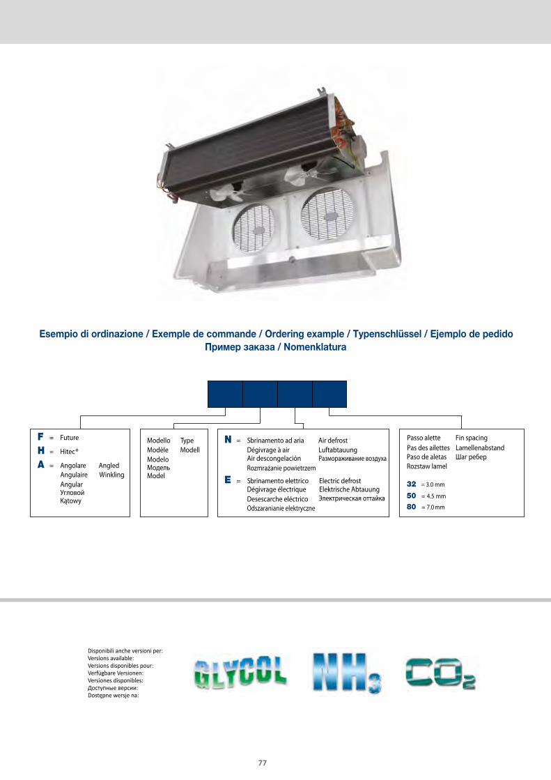
FHA 79 E 50
F = Future
H = Hitec®
A = Angolare AngledAngulaire WinklingAngularУгловойKątowy
Paso de aletas Шаг реберRozstaw lamel
ModeloМодельModel
Modello TypeModèle Modell
N = Sbrinamento ad aria Air defrostDégivrage à air Luftabtauung
E = Sbrinamento elettrico Electric defrostDégivrage électrique Elektrische Abtauung
Passo alette Fin spacingPas des ailettes Lamellenabstand
32 = 3.0 mm
50 = 4.5 mm
80 = 7.0 mm
Air descongelación Размораживание воздухаRozmrażanie powietrzem
Desescarche eléctrico Электрическая оттайкаOdszaranianie elektryczne
Disponibili anche versioni per:Versions available:Versions disponibles pour:Verfügbare Versionen:Versiones disponibles:Доступные версии:Dostępne wersje na:
77
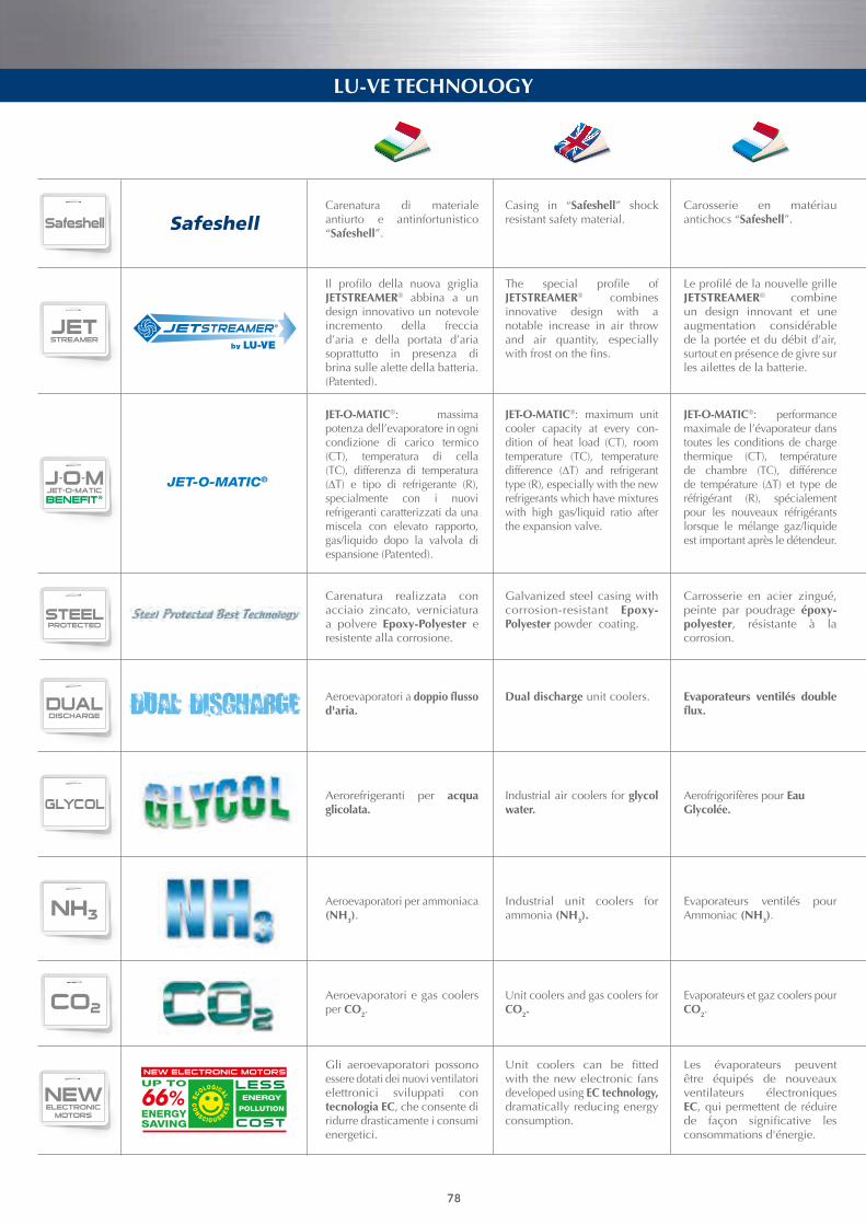
DUALDISCHARGE
STSSAFETUBES
SYSTEM
SMARTPATENTED
JETSTREAMER
J-O-MJET-O-MATIC
BENEFIT®STEELPROTECTED
DUALDISCHARGE
STSSAFETUBES
SYSTEM
SMARTPATENTED
JETSTREAMER
J-O-MJET-O-MATIC
BENEFIT®STEELPROTECTED
DRYAND
SPRAY
WATERSPRAY
SYSTEM
SMARTPATENTED
S.G.B.S. LESS
Safeshell
ENERGYSAVING
LU-VE TECHNOLOGY LU-VE TECHNOLOGY
Les évaporateurs peuvent être équipés de nouveaux ventilateurs électroniques EC, qui permettent de réduire de façon significative lesconsommations d'énergie.
Unit coolers can be fittedwith the new electronic fans developed using EC technology, dramatically reducing energy consumption.
Gli aeroevaporatori possono essere dotati dei nuovi ventilatori elettronici sviluppati con tecnologia EC, che consente di ridurre drasticamente i consumi energetici.
T.C.TURBOCOOLER
SUPERSILENT
EFFICIENT
NEWELECTRONIC
MOTORS
GLYCOL NH3 CO2
DUALDISCHARGE
STSSAFETUBES
SYSTEM
SMARTPATENTED
JETSTREAMER
J-O-MJET-O-MATIC
BENEFIT®STEELPROTECTED
DUALDISCHARGE
STSSAFETUBES
SYSTEM
SMARTPATENTED
JETSTREAMER
J-O-MJET-O-MATIC
BENEFIT®STEELPROTECTED
T.C.TURBOCOOLER
SUPERSILENT
EFFICIENT
NEWELECTRONIC
MOTORS
GLYCOL NH3 CO2
Carrosserie en acier zingué, peinte par poudrage époxy-polyester, résistante à la corrosion.
JET-O-MATIC®: performance maximale de l’évaporateur dans toutes les conditions de charge thermique (CT), température de chambre (TC), différence de température (∆T) et type deréfrigérant (R), spécialement pour les nouveaux réfrigérants lorsque le mélange gaz/liquide est important après le détendeur.
LeprofilédelanouvellegrilleJETSTREAMER® combine un design innovant et une augmentation considérable de la portée et du débit d’air, surtout en présence de givre sur les ailettes de la batterie.
Carosserie en matériau antichocs “Safeshell”.
Galvanized steel casing with corrosion-resistant Epoxy-Polyester powder coating.
JET-O-MATIC®: maximum unit cooler capacity at every con-dition of heat load (CT), room temperature (TC), temperature difference (∆T) and refrigeranttype (R), especially with the new refrigerants which have mixtures with high gas/liquid ratio after the expansion valve.
The special profile ofJETSTREAMER® combines innovative design with a notable increase in air throw and air quantity, especially withfrostonthefins.
Casing in “Safeshell” shock resistant safety material.
Dual discharge unit coolers.
Carenatura realizzata con acciaio zincato, verniciatura a polvere Epoxy-Polyester e resistente alla corrosione.
JET-O-MATIC®: massima potenza dell’evaporatore in ogni condizione di carico termico (CT), temperatura di cella (TC), differenza di temperatura (∆T) e tipo di refrigerante (R),specialmente con i nuovi refrigeranti caratterizzati da una miscela con elevato rapporto, gas/liquido dopo la valvola di espansione (Patented).
Il profilo della nuova grigliaJETSTREAMER® abbina a un design innovativo un notevole incremento della freccia d’aria e della portata d’aria soprattutto in presenza di brina sulle alette della batteria. (Patented).
Carenatura di materiale antiurto e antinfortunistico “Safeshell”.
Aeroevaporatori a doppio flusso d'aria.
Unit coolers and gas coolers for CO2.
Aeroevaporatori e gas coolers per CO2.
T.C.TURBOCOOLER
SUPERSILENT
EFFICIENT
NEWELECTRONIC
MOTORS
GLYCOL NH3 CO2Industrial air coolers for glycol water.
Aerorefrigeranti per acqua glicolata.
Aerofrigorifères pour Eau Glycolée.
T.C.TURBOCOOLER
SUPERSILENT
EFFICIENT
NEWELECTRONIC
MOTORS
GLYCOL NH3 CO2Industrial unit coolers for ammonia (NH3).
Aeroevaporatori per ammoniaca (NH3).
Evaporateurs ventilés pour Ammoniac (NH3).
Evaporateurs et gaz coolers pour CO2.
Evaporateurs ventilés double flux.
78
Safeshell
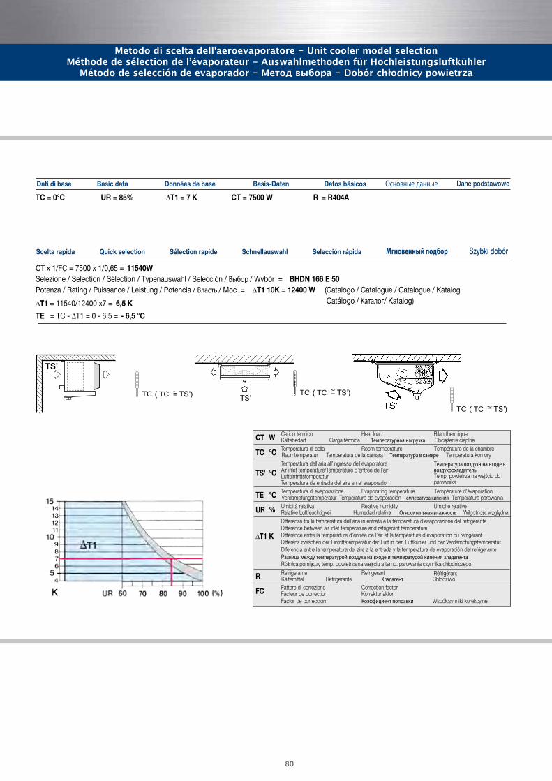
80
Metodo di sceltadell’aeroevaporatore
Unit cooler model selection
Méthode de sélection de l’évaporateur
Auswahlmethoden für Hochleistungsluftkühler
Método de selección de evaporador
Scelta rapida Quick selection Sélection rapide Schnellauswahl Selección rápida Мгновенный подбор Szybki dobór
TC = 0°C UR = 85% ∆T1 = 7 K CT = 7500 W R = R404A
CT x 1/FC = 7500 x 1/0,65 = 11540WSelezione / Selection / Sélection / Typenauswahl / Selección / Bыбор / Wybór = BHDN 166 E 50 Potenza / Rating / Puissance / Leistung / Potencia / Bласть / Moc = ∆T1 10K = 12400 W (Catalogo / Catalogue / Catalogue / Katalog
Catálogo / Kаталог/ Katalog)∆T1 = 11540/12400 x7 = 6,5 K
TE = TC - ∆T1 = 0 - 6,5 = - 6,5 °C
socisäb sotaDnetaD-sisaBesab ed seénnoDatad cisaBesab id itaD Основные данные Dane podstawowe
Метод выбора
Dobór chłodnicy powietrza
+10 +15-30 -25 -20 -15 -10 -5 0 +5
1.40
1.30
1.20
1.10
1.00
0.90
0.80
0.70
0.60
0.50
0.40
R= R134a
FC
TC (°C)
12K
11K
10K
9K
8K
7K
6K
∆T1
+10 +15-30 -25 -20 -15 -10 -5 0 +5
1.40
1.30
1.20
1.10
1.00
0.90
0.80
0.70
0.60
0.50
0.40
R= R22
FC
TC (°C)
12K
11K
10K
9K
8K
7K
6K
∆T1
+10 +15-30 -25 -20 -15 -10 -5 0 +5
1.40
1.30
1.20
1.10
1.00
0.90
0.80
0.70
0.60
0.50
0.40
R= R404A
FC
TC (°C)
12K
11K
10K
9K
8K
7K
6K
∆T1
FC Fattori di correzione della potenza / FC Capacity correction factors / FC Facteurs de correction de la puissance / FC Leistungs-Korrekturfaktoren / FC Factor de corrección de la potencia
FC Kоэффициент корректировки производительности / FC Współczynniki korekcyjne wydajności
Carico termico Heat load Bilan thermiqueCT W Kältebedarf Carga térmica Tемпературная нагрузка Obciążenie cieplneTemperatura di cella Room temperature Température de la chambreTC °C Raumtemperatur Temperatura de la cámara Tемпература в камере Temperatura komoryTemperatura dell’aria all’ingresso dell’evaporatore
TS’ °C Air inlet temperature/Temperature d’entrée de l’airLufteintrittstemperaturTemperatura de entrada del aire en el evaporadorTemperatura di evaporazione Evaporating temperature Température d’évaporationTE °C Verdampfungstemperatur Temperatura de evaporación Tемпература кипения Temperatura parowaniaUmidità relativa Relative humidity Umidité relativeUR % Relative Luftfeuchtigkei Humedad relativa Относительная влажность Wilgotność względnaDifferenza tra la temperatura dell’aria in entrata e la temperatura d’evaporazione del refrigeranteDifference between air inlet temperature and refrigerant temperature
∆T1 K Différence entre la température d’entrée de l’air et la température d’évaporation du réfrigérantDifferenz zwischen der Eintrittstemperatur der Luft in den Luftkühler und der Verdampfungstemperatur.Diferencia entre la temperatura del aire a la entrada y la temperatura de evaporación del refrigerantePазница между температурой воздуха на входе и температурой кипения хладагентаRóżnica pomiędzy temp. powietrza na wejściu a temp. parowania czynnika chłodniczego
R tnaregirfeRetnaregirfeR
FC Fattore di correzione Correction factor
RéfrigérantKältemittel Refrigerante Xладагент Chłodziwo
Facteur de correction KorrekturfaktorFactor de corrección Kоэффициент поправки Współczynniki korekcyjne
Tемпература воздуха на входе в воздухоохладитель Temp. powietrza na wejściu do parownika
TSʼ
TS”
TC ( TC = TSʼ)
TC ( TC = TSʼ)
TS’
TC ( TC = TSʼ)
Metodo di scelta dell'aeroevaporatore - Unit cooler model selectionMéthode de sélection de l’évaporateur - Auswahlmethoden für Hochleistungsluftkühler
Método de selección de evaporador - Метод выбора - Dobór chłodnicy powietrza
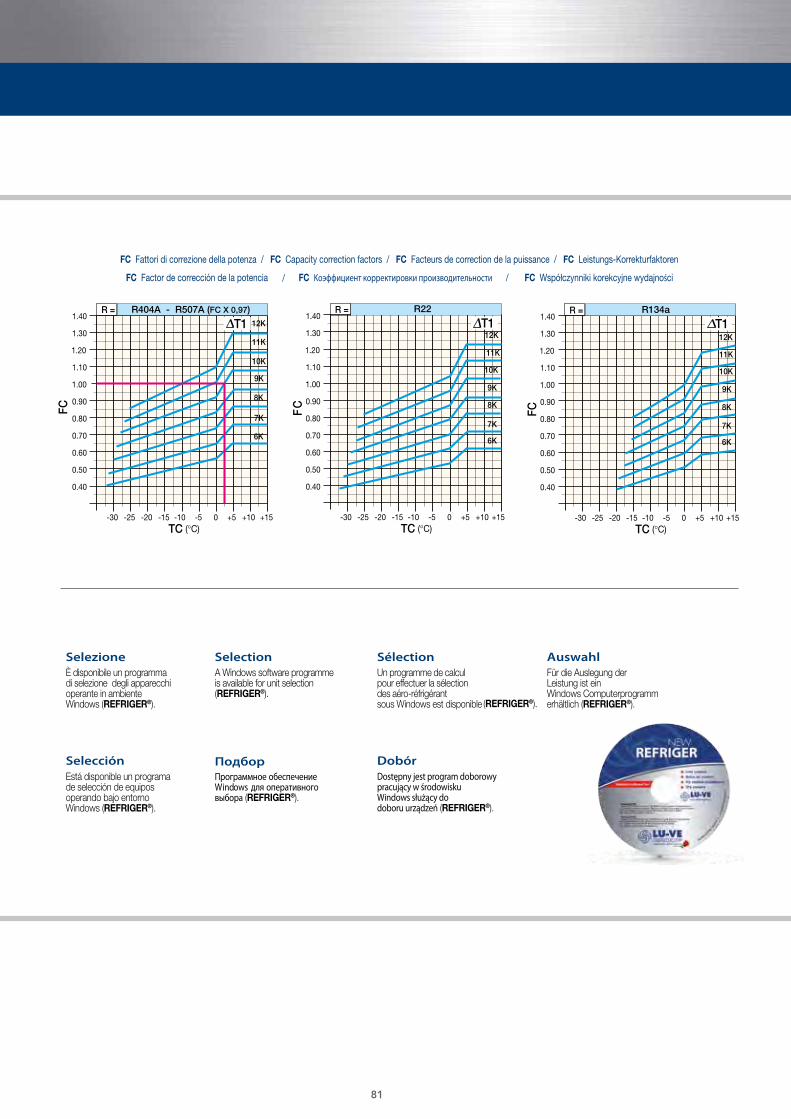
SHVC 120 N3 KW2,2 S H1
S = Super
H = Hitec®
V = VentilatoAir cooledVentiléLuftgekühltCondensador de aireС воздушным охлаждениемChłodzone powietrzem
C = CentrifugoCentrifugalCentrifugésRadialCentrífugoЦентробежныйZ wentylatorami promieniowymi
Pa = Pressione statica
Presión estática externaВнешнее статическое давление
Spręż dyspozycyjny
esternaExternal staticpressure
Pression statique externe
Äusserer statischerDruck
Esempio di ordinazione / Exemple de commande / Ordering example / Typenschlüssel / Ejemplo de pedido / Пример заказа / Przykładowe zamówienie
Selección Подбор
SelezioneÈ disponibile un programma di selezione degli apparecchi operante in ambiente Windows (REFRIGER®).
SélectionUn programme de calcul pour effectuer la sélection des aéro-réfrigérant sous Windows est disponible (REFRIGER®).
AuswahlFür die Auslegung der Leistung ist ein Windows Computerprogramm erhältlich (REFRIGER®).
DobórDostępny jest program doborowy pracujący w środowisku Windows służący do doboru urządzeń (REFRIGER®).
Está disponible un programa de selección de equipos operando bajo entorno Windows (REFRIGER®).
Программное обеспечениеWindows для оперативного выбора (REFRIGER®).
S = Batteria singola
С одной катушкойPojedyńczy wymiennik
С двумя катушкамиPodwójny wymiennik
Single coilBatterie uniqueEinzelbatterieBatería única
T = Batteria doppiaTwin coilBatterie doubleDoppelbatterieBatería doble
SelectionA Windows software programme is available for unit selection (REFRIGER®).
N = Numero motori
Номер мотора
Liczba silników
Мощность мотора
Moc silnika
Motor number
Nombre moteurs
Anzahl Motoren
Numero de motores
Kw = Potenza motori
Motor power
Puissance moteurs
Motoreleistung
Potencia del motor
V1 - V2H1 - H2L1 - L2
Posizione batteria
Расположение вентилятора и теплообменникаPozycja wymiennika i wentylatora
e ventilatori
Coil and fan position
Position batterie et ventilateur
Position Batterie und Lüfter
Posición de batería y ventilador
+10 +15-30 -25 -20 -15 -10 -5 0 +5
1.40
1.30
1.20
1.10
1.00
0.90
0.80
0.70
0.60
0.50
0.40
R= R134a
FC
TC (°C)
12K
11K
10K
9K
8K
7K
6K
∆T1
+10 +15-30 -25 -20 -15 -10 -5 0 +5
1.40
1.30
1.20
1.10
1.00
0.90
0.80
0.70
0.60
0.50
0.40
R= R22
FC
TC (°C)
12K
11K
10K
9K
8K
7K
6K
∆T1
+10 +15-30 -25 -20 -15 -10 -5 0 +5
1.40
1.30
1.20
1.10
1.00
0.90
0.80
0.70
0.60
0.50
0.40
R= R404A
FC
TC (°C)
12K
11K
10K
9K
8K
7K
6K
∆T1
FC Fattori di correzione della potenza / FC Capacity correction factors / FC Facteurs de correction de la puissance / FC Leistungs-Korrekturfaktoren / FC Factor de corrección de la potencia
FC Kоэффициент корректировки производительности / FC Współczynniki korekcyjne wydajności
Carico termico Heat load Bilan thermiqueCT W Kältebedarf Carga térmica Tемпературная нагрузка Obciążenie cieplneTemperatura di cella Room temperature Température de la chambreTC °C Raumtemperatur Temperatura de la cámara Tемпература в камере Temperatura komoryTemperatura dell’aria all’ingresso dell’evaporatore
TS’ °C Air inlet temperature/Temperature d’entrée de l’airLufteintrittstemperaturTemperatura de entrada del aire en el evaporadorTemperatura di evaporazione Evaporating temperature Température d’évaporationTE °C Verdampfungstemperatur Temperatura de evaporación Tемпература кипения Temperatura parowaniaUmidità relativa Relative humidity Umidité relativeUR % Relative Luftfeuchtigkei Humedad relativa Относительная влажность Wilgotność względnaDifferenza tra la temperatura dell’aria in entrata e la temperatura d’evaporazione del refrigeranteDifference between air inlet temperature and refrigerant temperature
∆T1 K Différence entre la température d’entrée de l’air et la température d’évaporation du réfrigérantDifferenz zwischen der Eintrittstemperatur der Luft in den Luftkühler und der Verdampfungstemperatur.Diferencia entre la temperatura del aire a la entrada y la temperatura de evaporación del refrigerantePазница между температурой воздуха на входе и температурой кипения хладагентаRóżnica pomiędzy temp. powietrza na wejściu a temp. parowania czynnika chłodniczego
R tnaregirfeRetnaregirfeR
FC Fattore di correzione Correction factor
RéfrigérantKältemittel Refrigerante Xладагент Chłodziwo
Facteur de correction KorrekturfaktorFactor de corrección Kоэффициент поправки Współczynniki korekcyjne
Tемпература воздуха на входе в воздухоохладитель Temp. powietrza na wejściu do parownika
+10 +15-30 -25 -20 -15 -10 -5 0 +5
1.40
1.30
1.20
1.10
1.00
0.90
0.80
0.70
0.60
0.50
0.40
R= R134a
FC
TC (°C)
12K
11K
10K
9K
8K
7K
6K
∆T1
+10 +15-30 -25 -20 -15 -10 -5 0 +5
1.40
1.30
1.20
1.10
1.00
0.90
0.80
0.70
0.60
0.50
0.40
R= R22
FC
TC (°C)
12K
11K
10K
9K
8K
7K
6K
∆T1
+10 +15-30 -25 -20 -15 -10 -5 0 +5
1.40
1.30
1.20
1.10
1.00
0.90
0.80
0.70
0.60
0.50
0.40
R= R404A
FC
TC (°C)
12K
11K
10K
9K
8K
7K
6K
∆T1
FC Fattori di correzione della potenza / FC Capacity correction factors / FC Facteurs de correction de la puissance / FC Leistungs-Korrekturfaktoren / FC Factor de corrección de la potencia
FC Kоэффициент корректировки производительности / FC Współczynniki korekcyjne wydajności
Carico termico Heat load Bilan thermiqueCT W Kältebedarf Carga térmica Tемпературная нагрузка Obciążenie cieplneTemperatura di cella Room temperature Température de la chambreTC °C Raumtemperatur Temperatura de la cámara Tемпература в камере Temperatura komoryTemperatura dell’aria all’ingresso dell’evaporatore
TS’ °C Air inlet temperature/Temperature d’entrée de l’airLufteintrittstemperaturTemperatura de entrada del aire en el evaporadorTemperatura di evaporazione Evaporating temperature Température d’évaporationTE °C Verdampfungstemperatur Temperatura de evaporación Tемпература кипения Temperatura parowaniaUmidità relativa Relative humidity Umidité relativeUR % Relative Luftfeuchtigkei Humedad relativa Относительная влажность Wilgotność względnaDifferenza tra la temperatura dell’aria in entrata e la temperatura d’evaporazione del refrigeranteDifference between air inlet temperature and refrigerant temperature
∆T1 K Différence entre la température d’entrée de l’air et la température d’évaporation du réfrigérantDifferenz zwischen der Eintrittstemperatur der Luft in den Luftkühler und der Verdampfungstemperatur.Diferencia entre la temperatura del aire a la entrada y la temperatura de evaporación del refrigerantePазница между температурой воздуха на входе и температурой кипения хладагентаRóżnica pomiędzy temp. powietrza na wejściu a temp. parowania czynnika chłodniczego
R tnaregirfeRetnaregirfeR
FC Fattore di correzione Correction factor
RéfrigérantKältemittel Refrigerante Xладагент Chłodziwo
Facteur de correction KorrekturfaktorFactor de corrección Kоэффициент поправки Współczynniki korekcyjne
Tемпература воздуха на входе в воздухоохладитель Temp. powietrza na wejściu do parownika
81
+10 +15-30 -25 -20 -15 -10 -5 0 +5
1.40
1.30
1.20
1.10
1.00
0.90
0.80
0.70
0.60
0.50
0.40
R = R22F
C
TC (°C)
12K
11K
10K
9K
8K
7K
6K
+15+10-30 -25 -20 -15 -10 -5 0 +5
1.40
1.30
1.20
1.10
1.00
0.90
0.80
0.70
0.60
0.50
0.40
R = R404A - R507A (FC X 0,97)
FC
TC (°C)
12K
11K
10K
9K
8K
7K
6K
T1
+10 +15-30 -25 -20 -15 -10 -5 0 +5
1.40
1.30
1.20
1.10
1.00
0.90
0.80
0.70
0.60
0.50
0.40
R = R134a
FCTC (°C)
12K
11K
10K
9K
8K
7K
6K
T1 T1
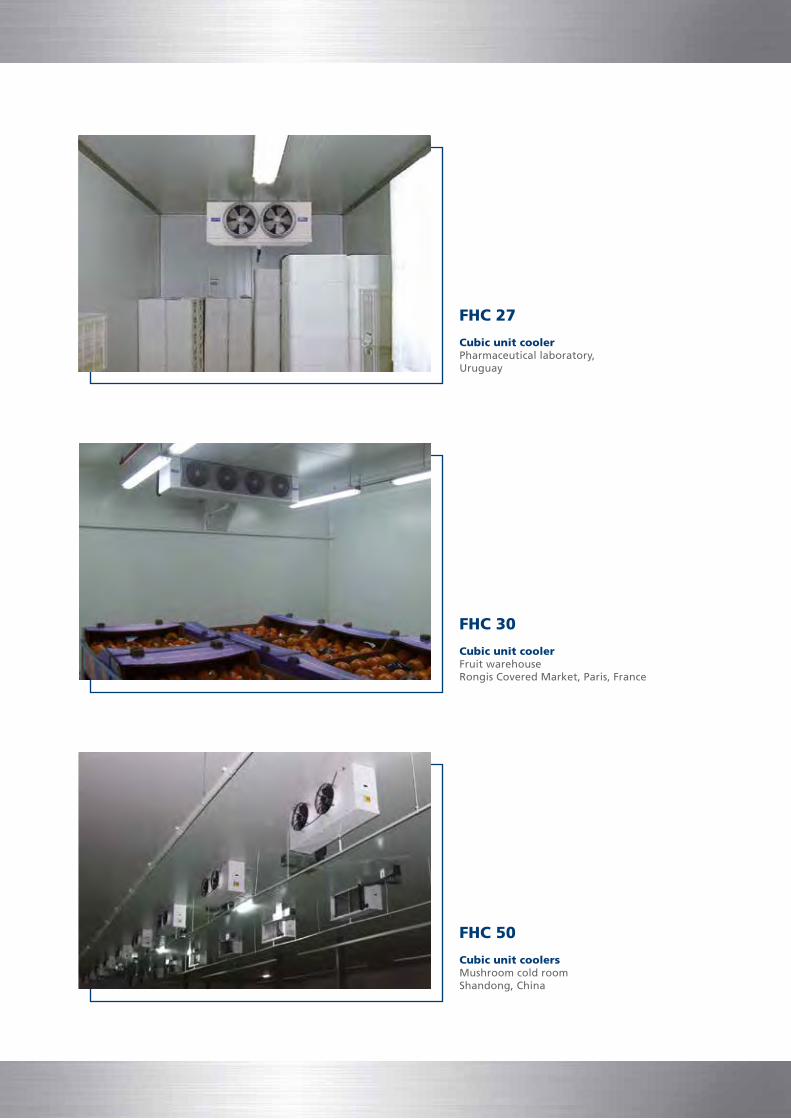
FHC 30
Cubic unit coolerFruit warehouseRongis Covered Market, Paris, France
FHC 27
Cubic unit coolerPharmaceutical laboratory,Uruguay
FHC 50
Cubic unit coolersMushroom cold room Shandong, China

BMA
Angled unit coolerSmall cold room for flowersMilan, Italy
FHD
Dual discharge unit coolersCatering facilitiesBirmingham, England
FHA
Angled unit coolersCheese warehouseParma, Italy
Cod
e 30
1697
55
09/1
5
LU-VE S.p.A.Via Caduti della Liberazione, 53 21040 Uboldo (Va)Tel: +39 02 96716.1e-mail: [email protected] www.luve.it
leadership with passion
Related Documents