
Welcome message from author
This document is posted to help you gain knowledge. Please leave a comment to let me know what you think about it! Share it to your friends and learn new things together.
Transcript

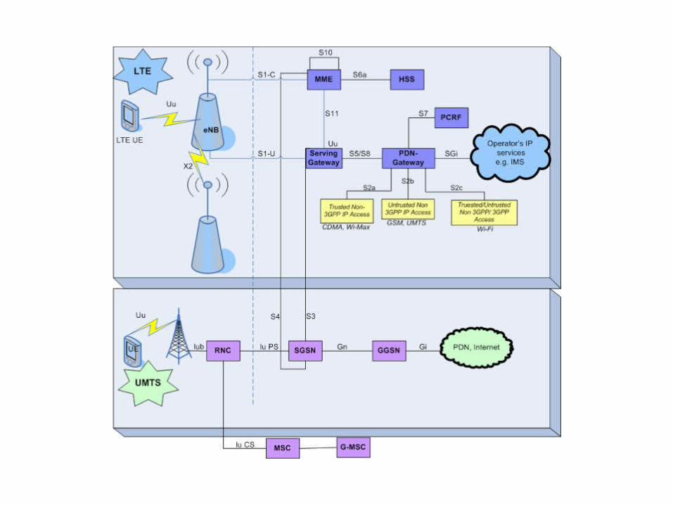
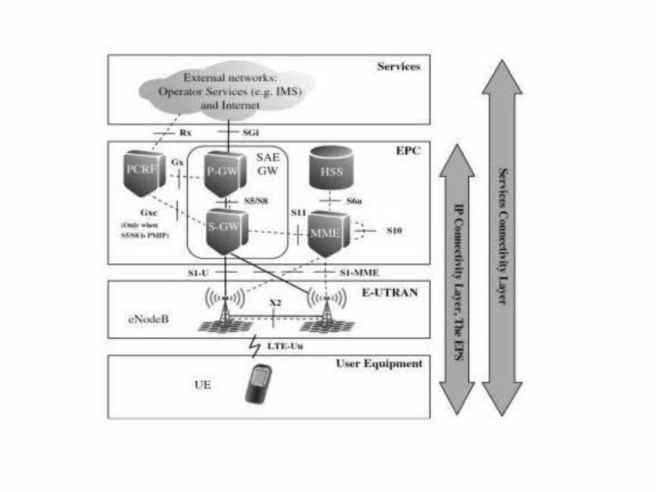

The LTE network is divided into 2 basic network, namely:1. E UTRAN (Evolved UniversalTerrestrial Radio Access Network)2. EPC (Evolved Packet Core)EPC• Functionally the EPC is equivalent to the packet switched domain of theexisting 3GPP networks.• EPC consist of :– MME ( Mobility Management Entity )– SAE GW represents the combination of the two gateways, ServingGateway (S-GW) and Packet Data Network Gateway (P-GW)– Home Subscriber Server (HSS)– Policy and Charging Rules Function (PCRF)( Evolved Universal Terrestrial Radio Access Network)Mobility Management Entity (MME)– MME is a controller at each node on the LTE access network. At UEin idle state (idle mode), MME is responsible for tracking andpaging procedure which includes retransmission therein.– MME is responsible for selecting SGW (Serving SAE Gateway)which will be used during initial attach EU and the EU time to dointra - LTE handover.– Used for bearer control, a different view R99 / 4 which is stillcontrolled by the gateway Policy and Charging Rules Function (PCRF)In order to handle QoS as well as control rating and charging, andbilling ï± Home Subscriber Server (HSS)�For management and security subscriber, combination AUC and HLR Serving SAE Gateway (SGW)- Set the path and forwards the data in the form of packets of each user- As an anchor / liaison between the UE and the eNB at the time of theinter handover- As a liaison link between the 3GPP LTE technology with the technology(in this case the 2G and 3G) Gateway Packet Data Network (PDN GW)- Provides for the UE 's relationship to the network packet- Provide a link relationship between LTE technology with technologynon 3GPP (WiMAX) and 3GPP2 (CDMA 20001X and EVDO)
E-UTRAN(Evolved Universal Terrestrial Radio Access Network) Role of Radio Access Network (RAN), namely Node B and RNC isreplaced with ENB, so as to reduce operational and maintenance costof the device other than the simpler network architecture E-nodeB functions : all radio protocols, mobility management, headercompression and all packet retransmissions As a network, E-UTRAN is simply a mesh of eNodeBs connected toneighboring eNodeBs with the X2 interface.User EquipmentFunctionally the UE is a platform for communicationapplications, which signal with the network for settingup, maintaining and removing the communication linksthe end user needs.ï± This includes mobility management functions such ashandovers and reporting the terminals location, and inthese the UE performs as instructed by the network

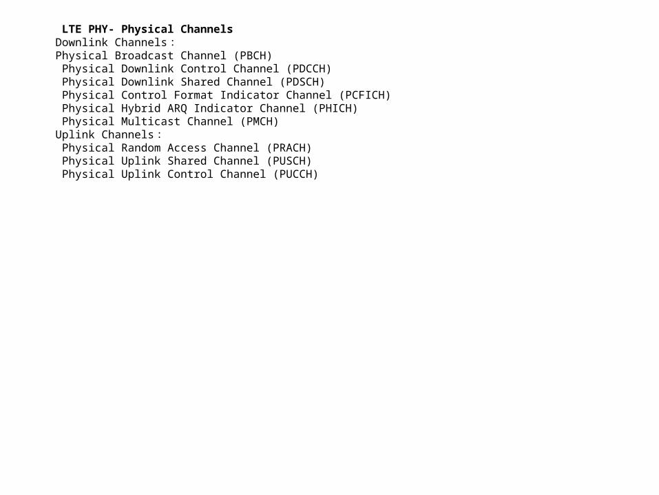
LTE PHY- Physical ChannelsDownlink Channels:Physical Broadcast Channel (PBCH) Physical Downlink Control Channel (PDCCH) Physical Downlink Shared Channel (PDSCH) Physical Control Format Indicator Channel (PCFICH) Physical Hybrid ARQ Indicator Channel (PHICH) Physical Multicast Channel (PMCH)Uplink Channels: Physical Random Access Channel (PRACH) Physical Uplink Shared Channel (PUSCH) Physical Uplink Control Channel (PUCCH)
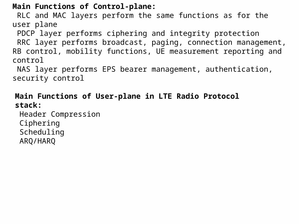
Main Functions of Control-plane: RLC and MAC layers perform the same functions as for the user plane PDCP layer performs ciphering and integrity protection RRC layer performs broadcast, paging, connection management, RB control, mobility functions, UE measurement reporting and control NAS layer performs EPS bearer management, authentication, security control
Main Functions of User-plane in LTE Radio Protocol stack: Header Compression Ciphering Scheduling ARQ/HARQ
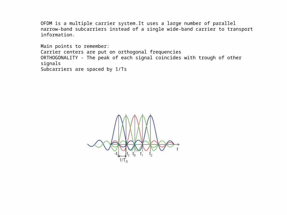
OFDM is a multiple carrier system.It uses a large number of parallel narrow-band subcarriers instead of a single wide-band carrier to transport information.
Main points to remember:Carrier centers are put on orthogonal frequenciesORTHOGONALITY - The peak of each signal coincides with trough of other signalsSubcarriers are spaced by 1/Ts

OFDMData is sent in parallel across the set of subcarriers, each subcarrier only transports a part of the whole transmission• The throughput is the sum of the data rates of each individual (or used) subcarriers while the power is distributed to all subcarriers• FFT (Fast Fourier Transform) is used to create the orthogonal subcarriers. The number of subcarriers is determined by the FFT size (by the bandwidth)• In LTE, these subcarriers are separated 15kHZMultipathMultipath causes Inter Symbol Interference (ISI) which affects the subcarrier orthogonality due to phase distortion• Solution to avoid ISI is to introduce a Guard Period (Tg) after the pulse– Tg needs to be long enough to capture all the delayed multipath signals

OFDM ParametersFrame duration: 10ms created from slots and subframes Subframe duration (TTI): 1 ms (composed of 2x0.5ms slots) Subcarrier spacing: Fixed to 15kHz (7.5 kHz defined for MBMS) Sampling Rate: Varies with the bandwidth but always factor or multiple of 3.84 to ensure compatibility with WCDMA by using common clocking.
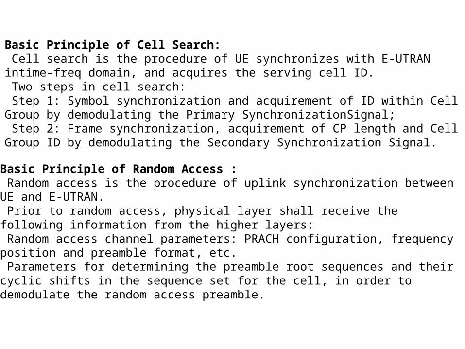
Basic Principle of Cell Search: Cell search is the procedure of UE synchronizes with E-UTRAN intime-freq domain, and acquires the serving cell ID. Two steps in cell search: Step 1: Symbol synchronization and acquirement of ID within Cell Group by demodulating the Primary SynchronizationSignal; Step 2: Frame synchronization, acquirement of CP length and Cell Group ID by demodulating the Secondary Synchronization Signal.
Basic Principle of Random Access : Random access is the procedure of uplink synchronization between UE and E-UTRAN. Prior to random access, physical layer shall receive the following information from the higher layers: Random access channel parameters: PRACH configuration, frequency position and preamble format, etc. Parameters for determining the preamble root sequences and their cyclic shifts in the sequence set for the cell, in order to demodulate the random access preamble.

What are the Characteristics of Synchronization Signal in LTE?
A User Equipment wishing to access the LTE system follows a cell search procedure which includes a series of synchronization stages by which the UE determines time and frequency parameters that are necessary to demodulate downlink signals, to transmit with correct timing and to acquire some critical system parameters.
There are three synchronization requirements in LTE: symbol timing acquisition by which the correct symbol start is determined; carrier frequency synchronization which mitigates the effect of frequency errors resulting from Doppler shift and errors from electronics; and sampling clock synchronization.
There are two cell search procedures in LTE: one for initial synchronization and another for detecting neighbor cells in preparation for handover. In both cases, the UE uses two special signals broadcast on each cell: Primary Synchronization Sequence (PSS) and Secondary Synchronization Sequence (SSS). The detection of these signals allows the UE to complete time and frequency synchronization and to acquire useful system parameters such as cell identity, cyclic prefix length, and access mode (FDD/TDD). At this stage, the UE can also decode the PhysicalBroadcast Control Channel (PBCH) and obtain important system information.
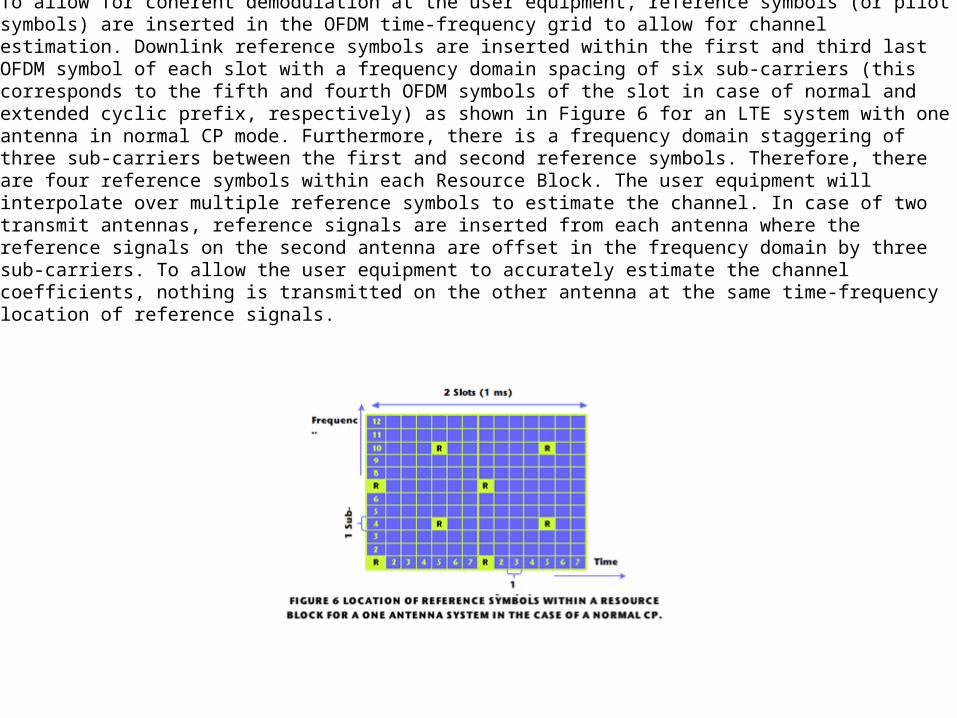
Downlink Reference SignalsTo allow for coherent demodulation at the user equipment, reference symbols (or pilot symbols) are inserted in the OFDM time-frequency grid to allow for channel estimation. Downlink reference symbols are inserted within the first and third last OFDM symbol of each slot with a frequency domain spacing of six sub-carriers (this corresponds to the fifth and fourth OFDM symbols of the slot in case of normal and extended cyclic prefix, respectively) as shown in Figure 6 for an LTE system with one antenna in normal CP mode. Furthermore, there is a frequency domain staggering of three sub-carriers between the first and second reference symbols. Therefore, there are four reference symbols within each Resource Block. The user equipment will interpolate over multiple reference symbols to estimate the channel. In case of two transmit antennas, reference signals are inserted from each antenna where the reference signals on the second antenna are offset in the frequency domain by three sub-carriers. To allow the user equipment to accurately estimate the channel coefficients, nothing is transmitted on the other antenna at the same time-frequency location of reference signals.
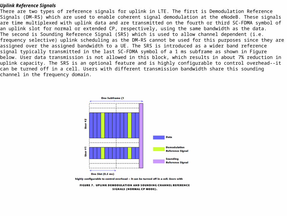
Uplink Reference SignalsThere are two types of reference signals for uplink in LTE. The first is Demodulation Reference Signals (DM-RS) which are used to enable coherent signal demodulation at the eNodeB. These signals are time multiplexed with uplink data and are transmitted on the fourth or third SC-FDMA symbol of an uplink slot for normal or extended CP, respectively, using the same bandwidth as the data.The second is Sounding Reference Signal (SRS) which is used to allow channel dependent (i.e. frequency selective) uplink scheduling as the DM-RS cannot be used for this purposes since they are assigned over the assigned bandwidth to a UE. The SRS is introduced as a wider band reference signal typically transmitted in the last SC-FDMA symbol of a 1 ms subframe as shown in Figure below. User data transmission is not allowed in this block, which results in about 7% reduction in uplink capacity. The SRS is an optional feature and is highly configurable to control overhead--it can be turned off in a cell. Users with different transmission bandwidth share this sounding channel in the frequency domain.
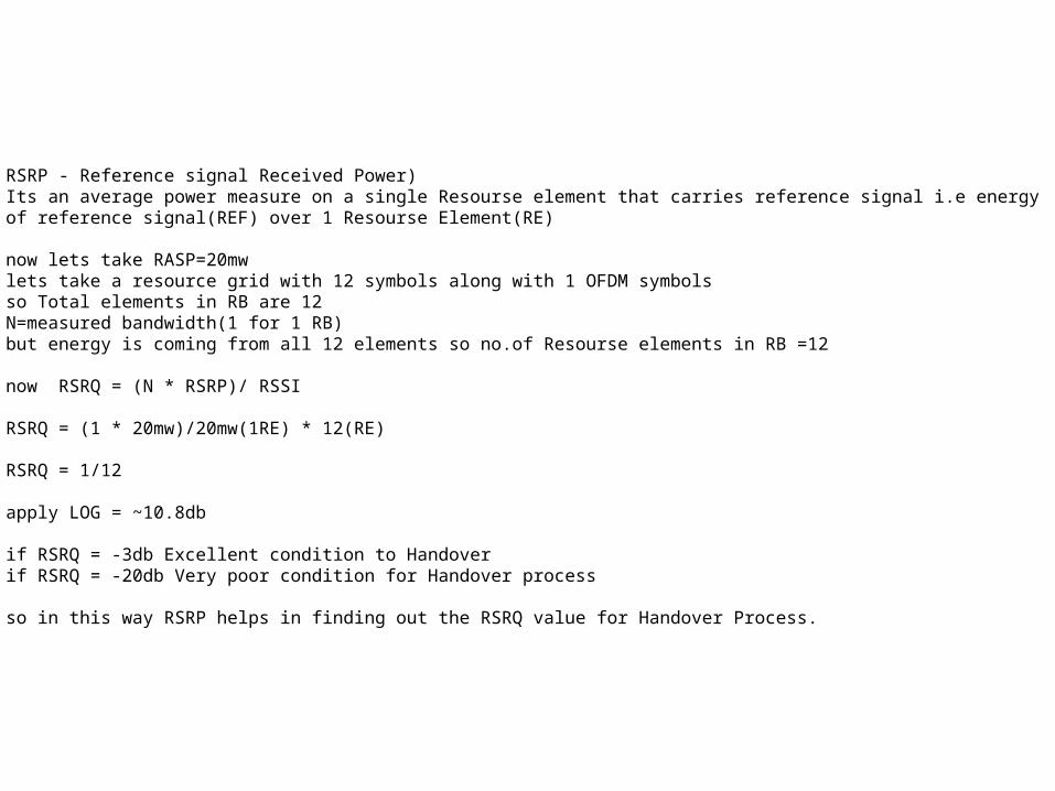
RSRP - Reference signal Received Power) Its an average power measure on a single Resourse element that carries reference signal i.e energy of reference signal(REF) over 1 Resourse Element(RE)
now lets take RASP=20mwlets take a resource grid with 12 symbols along with 1 OFDM symbolsso Total elements in RB are 12N=measured bandwidth(1 for 1 RB)but energy is coming from all 12 elements so no.of Resourse elements in RB =12
now RSRQ = (N * RSRP)/ RSSI
RSRQ = (1 * 20mw)/20mw(1RE) * 12(RE)
RSRQ = 1/12
apply LOG = ~10.8db
if RSRQ = -3db Excellent condition to Handover if RSRQ = -20db Very poor condition for Handover process
so in this way RSRP helps in finding out the RSRQ value for Handover Process.
Lack of a dominant cell: In an area without a dominant cell, the receive level of the serving cell is similar to the receive levels of its neighboring cells and the receive levels of downlink signals between different cells are close to cell reselection thresholds. Receive levels in an area without a dominant cell are also unsatisfactory. The SINR of the serving cell becomes unstable because of frequency reuse, and even receive quality becomes unsatisfactory. In this situation, a dominant cell is frequently reselected and changed in idle mode. As a result,frequent handovers or service drops occur on UEs in connected mode because of poor signal quality. An area without a dominant cell can also be regarded as a weak coverage area.
Solution of Lack of Dominant Cells Problems: Determine cells covering an area without a dominant cell during network planning, and adjust antenna tilts and azimuths to increase coverage by a cell with strong signals and decrease coverage of other cells with weak signals. Adjust engineering parameters of a cell that can optimally cover the area as required.
Resolving Signal Quality Problems:Optimizing frequencies-Change and optimize frequencies based on drive test and performance measurement data.
Adjusting the antenna system - Adjust antenna azimuths and tilts to change the distribution of signals in an interfered area by increasing the level of a dominant sector and decreasing levels ofother sectors.
Adding dominant coverage - Increase power of a cell and decrease power of other cells to form a dominant cell.
Adjusting power- Decrease RS power to reduce coverage if the antenna pattern is distorted because of a large antenna tilt. Power adjustment and antenna system adjustment can be used together.
Co-Channel Inteference:•This type of interference is the due to frequency reuse , i.e. several cells use the same set of frequency.•These cells are called co-channel cells.•Co-channel interference cannot be combated by increasing the power of the transmitter. This is because an increase in carrier transmit power increases the interference to neighboring co-channel cells.•To reduce co-channel interference, co-channel cells must be physically separated by a minimum distance to provide sufficient isolation due to propagation or reduce the footprint of the cell. Adjacent Channel Inteference:•Interference resulting from signals which are adjacent in frequency to the desired signal is called adjacent channel interference.•Adjacent channel interference results from imperfect receiver filters which allow nearby frequencies to leak into the passband.•Adjacent channel interference can be minimized through careful filtering and channel assignments.By keeping the frequency separation between each channel in a given cell as large as possible , the adjacent interference may be reduced considerably.
Resolving Problems with Imbalance Between Uplink and Downlink:If no performance data is available for RF optimization, trace a single user in the OMC equipment room to obtain uplink measurement reports on the Uu interface, and then analyze the measurement reports and drive test files.If performance data is available, check each carrier in each cell for imbalance between uplink and downlink based on uplink and downlink balance measurements.If uplink interference leads to imbalance between uplink and downlink, monitor eNodeB alarms to check for interference.Check whether equipment works properly and whether alarms are generated if imbalance between uplink and downlink is caused by other factors, for example, uplink and downlink gains of repeaters and trunk amplifiers are set incorrectly, the antenna system for receive diversity is faulty when reception and transmission are separated, or power amplifiers are faulty. If equipment works properly or alarms are generated, take measures such as replacement, isolation, and adjustment.
What is Uplink & Downlink Imbalance?MS can not transmit & receipt signal, the call drop will happen when BTS can not allocated channel also known as uplink & downlink imbalance.
Solution of Cross Coverage problems in LTE:Adjust antenna azimuths properly so that the direction of the main lobe slightlyobliques from the direction of a street. This reduces excessively far coverage byelectric waves because of reflection from buildings on two sides of the street.
Adjust antenna tilts or replace antennas with large-tilt antennas while ensuringproper antenna azimuths. Tilt adjustment is the most effective approach to controlcoverage. Tilts are classified into electrical tilts and mechanical tilts. Electrical tiltsare preferentially adjusted if possible.
Decrease the antenna height for a high site.
Decrease transmit power of carriers when cell performance is not affected.
Cross Coverage in LTE RF Optimization: Cross coverage means that the coverage scope of an eNodeB exceeds the planned one and generates discontinuous dominant areas in the coverage scope of other eNodeBs. For example, if the height of a site is much higher than the average height of surrounding buildings, its transmit signals propagate far along hills or roads and form dominant coverage in the coverage scope of other eNodeBs. This is an “island†phenomenon.�
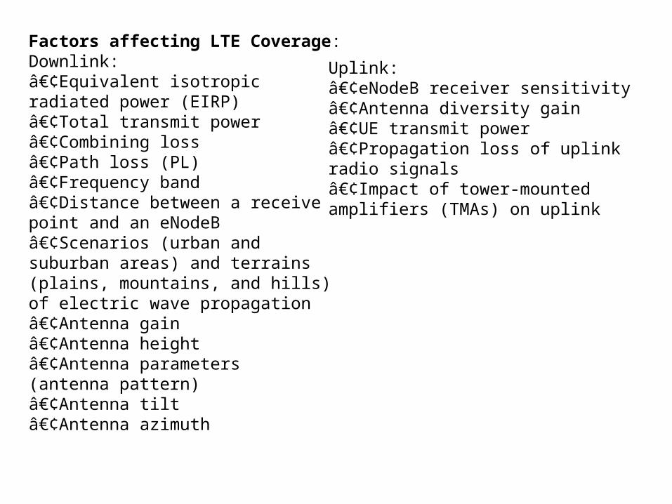
Factors affecting LTE Coverage:Downlink:•Equivalent isotropicradiated power (EIRP)•Total transmit power•Combining loss•Path loss (PL)•Frequency band•Distance between a receivepoint and an eNodeB•Scenarios (urban andsuburban areas) and terrains(plains, mountains, and hills)of electric wave propagation•Antenna gain•Antenna height•Antenna parameters(antenna pattern)•Antenna tilt•Antenna azimuth
Uplink:•eNodeB receiver sensitivity•Antenna diversity gain•UE transmit power•Propagation loss of uplinkradio signals•Impact of tower-mountedamplifiers (TMAs) on uplink
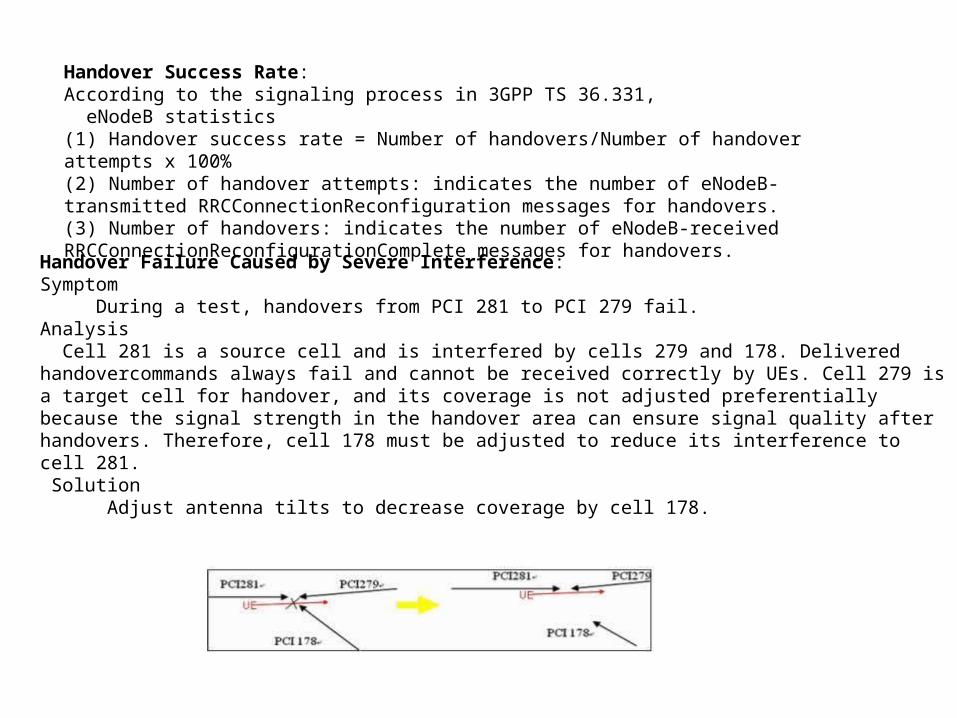
Handover Failure Caused by Severe Interference:Symptom During a test, handovers from PCI 281 to PCI 279 fail.Analysis Cell 281 is a source cell and is interfered by cells 279 and 178. Delivered handovercommands always fail and cannot be received correctly by UEs. Cell 279 is a target cell for handover, and its coverage is not adjusted preferentially because the signal strength in the handover area can ensure signal quality after handovers. Therefore, cell 178 must be adjusted to reduce its interference to cell 281. Solution Adjust antenna tilts to decrease coverage by cell 178.
Handover Success Rate:According to the signaling process in 3GPP TS 36.331, eNodeB statistics(1) Handover success rate = Number of handovers/Number of handoverattempts x 100%(2) Number of handover attempts: indicates the number of eNodeB-transmitted RRCConnectionReconfiguration messages for handovers.(3) Number of handovers: indicates the number of eNodeB-receivedRRCConnectionReconfigurationComplete messages for handovers.

What is the Basic Principle of Power Control in LTE?
Principle : The transmission power is adapted in order to achieve the desired QoS (BLER/BER). This adaptation is necessary since the propagation channel is subject to several conditions, which generally vary in space and/or time,e.g.• path loss• log normal fading• short term fading• UE speed• location (outdoor, indoor, in-car) etc.Downlink power control determines the energy per resource element (EPRE). The term resource element energy denotes the energy prior to CP insertion. The term resource element energy also denotes the average energy taken over all constellation points for the modulation scheme applied.Uplink power control determines the average power over a DFT-SOFDM symbol in which the physical channel is transmitted. In contrast to UTRAN based on WCDMA however the requirements for UL power control are more relaxed as a similar near-far problem of UTRAN does not exist. Compared with UTRAN the UL power control is slower. The PUSCH and the PUCCH are subject to a combined open and closed loop power control algorithm, i.e. to control the transmission power for UL channels a combination of an open (input: pathless, sysinfo and signaling) and a closed loop (TPC) method is used.A cell wide overload indicator (OI) and a High Interference Indicator (HII) to control UL interference are exchanged over X2. An indication is given which PRBs an eNodeB scheduler allocates to cell edge UEs and hence will be most sensitive to inter-cell interference.

Related Documents


![Presentation1.Ppt Auto Saved]](https://static.cupdf.com/doc/110x72/5571fe3249795991699ad8f9/presentation1ppt-auto-saved.jpg)
