The most important thing we build is trust PXI LTE FDD and LTE TDD Measurement Suites Data Sheet • A production ready ATE solution for RF alignment and per- formance verification • UE Tx output power • Transmit power • PRACH time mask • Transmit signal quality: • Frequency error • Error Vector Magnitude (EVM) • Spectrum flatness • Carrier leakage (IQ origin offset) • In-band emissions for non allocated RB • IQ skew/gain imbalance • Symbol clock error • Output RF spectrum emissions: • Occupied bandwidth • Spectrum Emission Mask (SEM) • Adjacent Channel Leakage power Ratio (ACLR) • CCDF The LTE measurement suite is a collection of software tools for use with PXI 3000 Series RF modular instruments for characterising the performance of LTE FDD and TDD mobile devices in accordance with the methods described in ETSI TS 36.521-1. Using the measurement suite with PXI 3000 RF modular instruments simplifies test system integration and increases test speed to accelerate new product introduction and lower the cost of test. The measurement suite is ideal for performing all non signalling mode RF alignment and performance verification measurements for mobile UE production test.

Welcome message from author
This document is posted to help you gain knowledge. Please leave a comment to let me know what you think about it! Share it to your friends and learn new things together.
Transcript
The most important thing we build is trust
PXILTE FDD and LTE TDD Measurement Suites
Data Sheet
• A production ready ATE solution for RF alignment and per-formance verification
• UE Tx output power
• Transmit power
• PRACH time mask
• Transmit signal quality:
• Frequency error
• Error Vector Magnitude (EVM)
• Spectrum flatness
• Carrier leakage (IQ origin offset)
• In-band emissions for non allocated RB
• IQ skew/gain imbalance
• Symbol clock error
• Output RF spectrum emissions:
• Occupied bandwidth
• Spectrum Emission Mask (SEM)
• Adjacent Channel Leakage power Ratio (ACLR)
• CCDF
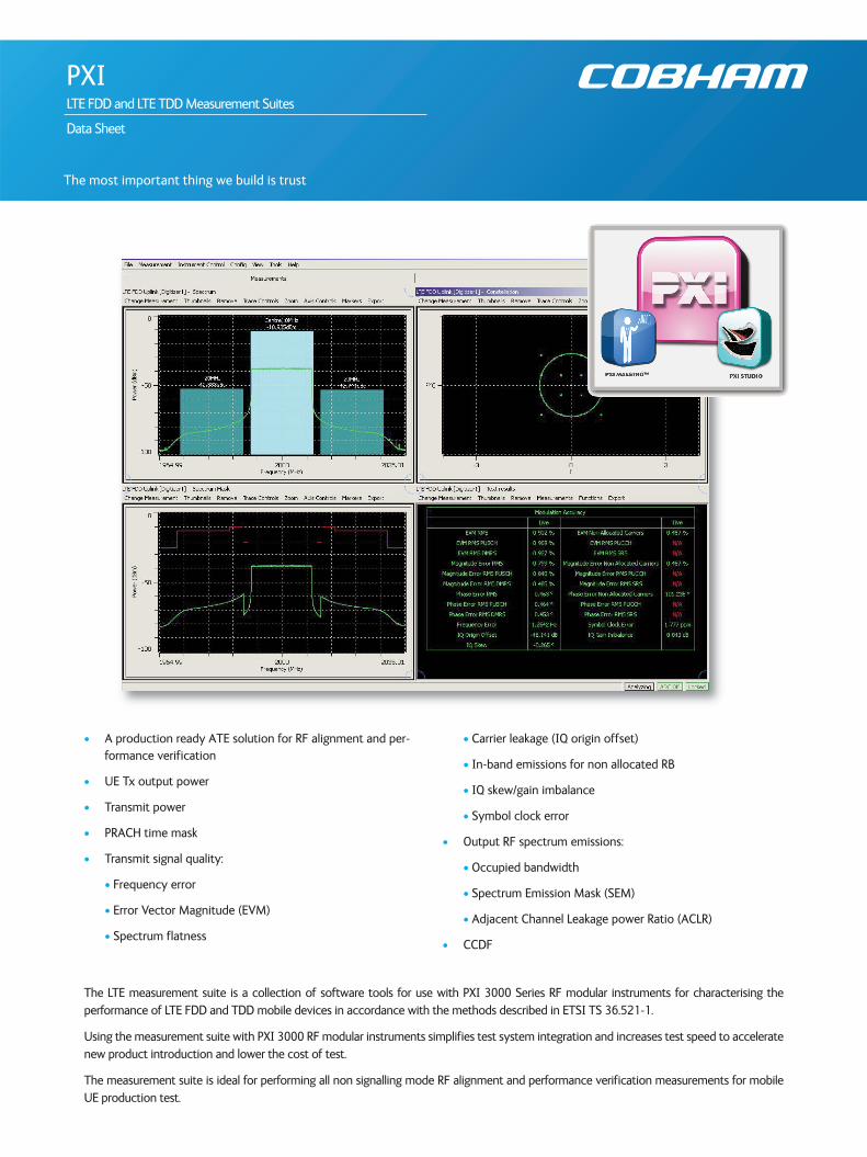
The LTE measurement suite is a collection of software tools for use with PXI 3000 Series RF modular instruments for characterising the performance of LTE FDD and TDD mobile devices in accordance with the methods described in ETSI TS 36.521-1.
Using the measurement suite with PXI 3000 RF modular instruments simplifies test system integration and increases test speed to acceleratenew product introduction and lower the cost of test.
The measurement suite is ideal for performing all non signalling mode RF alignment and performance verification measurements for mobileUE production test.
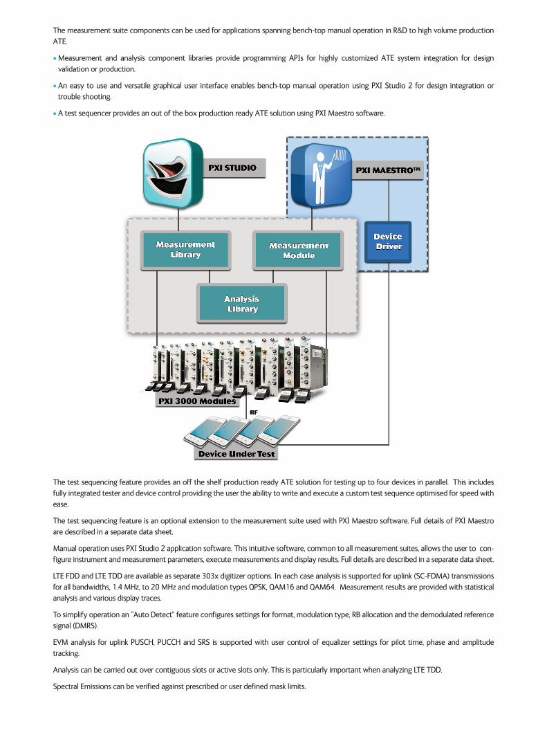
The measurement suite components can be used for applications spanning bench-top manual operation in R&D to high volume productionATE.
• Measurement and analysis component libraries provide programming APIs for highly customized ATE system integration for design validation or production.
• An easy to use and versatile graphical user interface enables bench-top manual operation using PXI Studio 2 for design integration or trouble shooting.
• A test sequencer provides an out of the box production ready ATE solution using PXI Maestro software.
The test sequencing feature provides an off the shelf production ready ATE solution for testing up to four devices in parallel. This includesfully integrated tester and device control providing the user the ability to write and execute a custom test sequence optimised for speed withease.
The test sequencing feature is an optional extension to the measurement suite used with PXI Maestro software. Full details of PXI Maestroare described in a separate data sheet.
Manual operation uses PXI Studio 2 application software. This intuitive software, common to all measurement suites, allows the user to con-figure instrument and measurement parameters, execute measurements and display results. Full details are described in a separate data sheet.
LTE FDD and LTE TDD are available as separate 303x digitizer options. In each case analysis is supported for uplink (SC-FDMA) transmissionsfor all bandwidths, 1.4 MHz, to 20 MHz and modulation types QPSK, QAM16 and QAM64. Measurement results are provided with statisticalanalysis and various display traces.
To simplify operation an “Auto Detect” feature configures settings for format, modulation type, RB allocation and the demodulated referencesignal (DMRS).
EVM analysis for uplink PUSCH, PUCCH and SRS is supported with user control of equalizer settings for pilot time, phase and amplitude tracking.
Analysis can be carried out over contiguous slots or active slots only. This is particularly important when analyzing LTE TDD.
Spectral Emissions can be verified against prescribed or user defined mask limits.
SPECIFICATION
LTE FDD AND TDD
All specifications are defined when used in conjunction with the 3030 Series PXI RF digitizer with option 107 (FDD) and option 108 (TDD)operating in all E-UTRA FDD and TDD bands. Test sequencing with PXI Maestro additionally requires option 207.
Measurements performed are in accordance with 3GPP 36.521-1 section 6.
LTE FDD and LTE TDD measurement suites are supplied separately.
Specifications are defined with the input signal at the RF digitizer tuned frequency and at the reference level unless otherwise stated.
CONFIGURATION
Frequency
User defined frequency (Hz) or preset E-UARFCN bands, 1 to 21
Level
Uplink (DUT output level) (dBm)
Path Loss Correction
Uplink (dB)
Physical Channel
Normal, PRACH
Nominal Bandwidth
1.4, 3, 5, 10, 15 and 20 MHz
Sub-frames (link direction)
Uplink
BURST SET UP
Burst Type
Uplink PUSCH: Normal data
MEASUREMENT SET-UP
Cell ID
0 to 503
Cyclic Prefix Type
Normal or Extended
EVM Window Position
Low, middle or high
Analysis Mode
Random slot or Specific slot
Spectrum Analysis Mode(3)
Measure all IQ data or specified number of slots
Number of Slots to Analyze
Dependent on measurement interval
Measurements can be performed for slots which are active and also for slots which are active and contiguous.
1 to 360
EVM Enable Conformance Mode
On / Off
Signal Composition(2)
Uplink & Downlink or Uplink only
Uplink Cyclic Prefix Type(2)
Normal or Extended
Downlink Cyclic Prefix Type(2)
Normal or Extended
(2) Available in LTE TDD only(3) Available in LTE FDD only
Uplink-Downlink Configuration(2)
1 to 6 as defined in table 4.2-2 of 3GPP TS36.211 v8.6.0 (2009-03)
Special Sub-frame Configuration(2)
1 to 8 as defined in table 4.2-1 of 3GPP TS36.211 v8.6.0 (2009-03)
Synchronization Slot (for specific slot analysis only)
0 to 19
Half Subcarrier Shift
On / Off
DTX Present(3)
On / Off
PILOT TRACKING
Phase Tracking
On / Off
Amplitude Tracking
On / Off
Symbol Time Tracking
On / Off
PRACH ANALYSIS SETUP
High Speed Flag
On / Off
NCS Configuration
0 to 15
Logical Root Sequence Number
0 to 837 as defined in section 5.7.2 of 3GPP TS 36.211 v8.9.0 (2009-12)
MEASUREMENTS
Start position (in μs)
Preamble ID
Preamble format
On power (dBm)
Leading off power (dBm)
Trailing off power (dBm)
Trailing gap off power (dBm)
RB offset
Trace
PRACH Power vs. Time
Power vs. Frequency
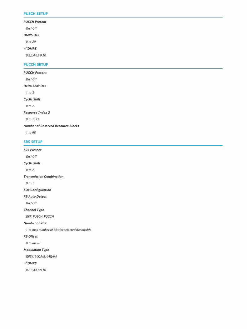
PUSCH SETUP
PUSCH Present
On / Off
DMRS Dss
0 to 29
n(2)DMRS
0,2,3,4,6,8,9,10
PUCCH SETUP
PUCCH Present
On / Off
Delta Shift Dss
1 to 3
Cyclic Shift
0 to 7
Resource Index 2
0 to 1175
Number of Reserved Resource Blocks
1 to 98
SRS SETUP
SRS Present
On / Off
Cyclic Shift
0 to 7
Transmission Combination
0 to 1
Slot Configuration
RB Auto Detect
On / Off
Channel Type
OFF, PUSCH, PUCCH
Number of RBs
1 to max number of RBs for selected Bandwidth
RB Offset
0 to max-1
Modulation Type
QPSK, 16QAM, 64QAM
n(2)DMRS
0,2,3,4,6,8,9,10
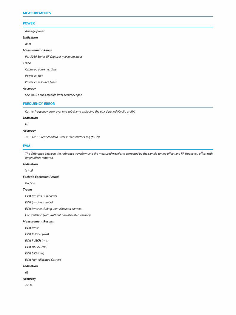
MEASUREMENTS
POWER
Average power
Indication
dBm
Measurement Range
Per 3030 Series RF Digitizer maximum input
Trace
Captured power vs. time
Power vs. slot
Power vs. resource block
Accuracy
See 3030 Series module level accuracy spec
FREQUENCY ERROR
Carrier frequency error over one sub-frame excluding the guard period (Cyclic prefix)
Indication
Hz
Accuracy
<±10 Hz + (Freq Standard Error x Transmitter Freq (MHz))
EVM
The difference between the reference waveform and the measured waveform corrected by the sample timing offset and RF frequency offset withorigin offset removed.
Indication
% / dB
Exclude Exclusion Period
On / Off
Traces
EVM (rms) vs. sub-carrier
EVM (rms) vs. symbol
EVM (rms) excluding non allocated carriers
Constellation (with /without non allocated carriers)
Measurement Results
EVM (rms)
EVM PUCCH (rms)
EVM PUSCH (rms)
EVM DMRS (rms)
EVM SRS (rms)
EVM Non Allocated Carriers
Indication
dB
Accuracy
<±1%
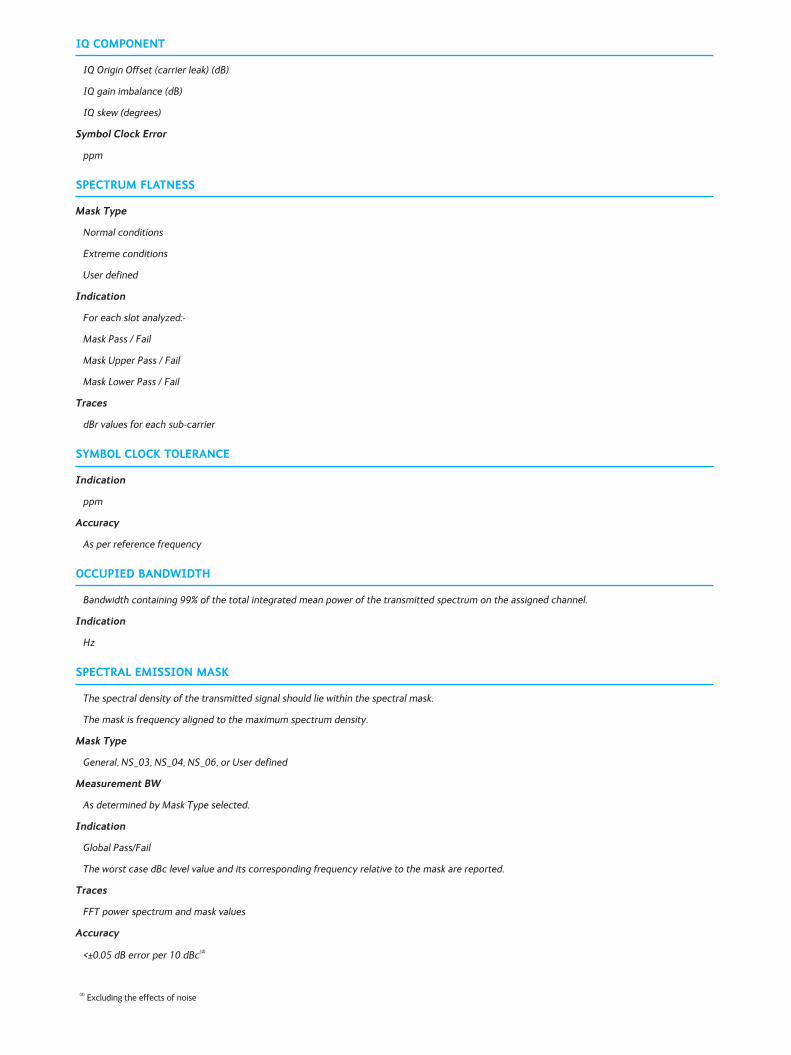
IQ COMPONENT
IQ Origin Offset (carrier leak) (dB)
IQ gain imbalance (dB)
IQ skew (degrees)
Symbol Clock Error
ppm
SPECTRUM FLATNESS
Mask Type
Normal conditions
Extreme conditions
User defined
Indication
For each slot analyzed:-
Mask Pass / Fail
Mask Upper Pass / Fail
Mask Lower Pass / Fail
Traces
dBr values for each sub-carrier
SYMBOL CLOCK TOLERANCE
Indication
ppm
Accuracy
As per reference frequency
OCCUPIED BANDWIDTH
Bandwidth containing 99% of the total integrated mean power of the transmitted spectrum on the assigned channel.
Indication
Hz
SPECTRAL EMISSION MASK
The spectral density of the transmitted signal should lie within the spectral mask.
The mask is frequency aligned to the maximum spectrum density.
Mask Type
General, NS_03, NS_04, NS_06, or User defined
Measurement BW
As determined by Mask Type selected.
Indication
Global Pass/Fail
The worst case dBc level value and its corresponding frequency relative to the mask are reported.
Traces
FFT power spectrum and mask values
Accuracy
<±0.05 dB error per 10 dBc(4)
(4) Excluding the effects of noise
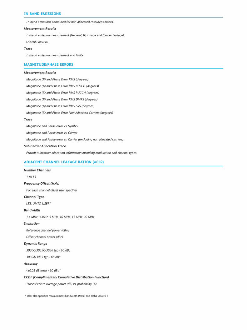
IN-BAND EMISSIONS
In-band emissions computed for non-allocated resources blocks.
Measurement Results
In-band emission measurement (General, IQ Image and Carrier leakage):
Overall Pass/Fail
Trace
In-band emission measurement and limits
MAGNITUDE/PHASE ERRORS
Measurement Results
Magnitude (%) and Phase Error RMS (degrees)
Magnitude (%) and Phase Error RMS PUSCH (degrees)
Magnitude (%) and Phase Error RMS PUCCH (degrees)
Magnitude (%) and Phase Error RMS DMRS (degrees)
Magnitude (%) and Phase Error RMS SRS (degrees)
Magnitude (%) and Phase Error Non Allocated Carriers (degrees)
Trace
Magnitude and Phase error vs. Symbol
Magnitude and Phase error vs. Carrier
Magnitude and Phase error vs. Carrier (excluding non allocated carriers)
Sub Carrier Allocation Trace
Provide subcarrier allocation information including modulation and channel types.
ADJACENT CHANNEL LEAKAGE RATION (ACLR)
Number Channels
1 to 15
Frequency Offset (MHz)
For each channel offset user specifier
Channel Type:
LTE, UMTS, USER*
Bandwidth
1.4 MHz, 3 MHz, 5 MHz, 10 MHz, 15 MHz, 20 MHz
Indication
Reference channel power (dBm)
Offset channel power (dBc)
Dynamic Range
3030C/3035C/3036 typ - 65 dBc
3030A/3035 typ - 68 dBc
Accuracy
<±0.05 dB error / 10 dBc(4)
CCDF (Complimentary Cumulative Distribution Function)
Trace: Peak to average power (dB) vs. probability (%)
* User also specifies measurement bandwidth (MHz) and alpha value 0-1
GENERAL
Operating System
Windows Win7/32 bit or Win 7/64 bit
Required Memory
512 Mbytes minimum, 1024 Mbytes recommended
Display Resolution
Minimum 1024 x 768
Other
PXI 3000 Series modules require NI VISA version 4.6 or later (NI Visa 4.2 or later under Windows® Vista).
PXI 3000 Series module drivers version 7.0.0 or later
ORDERING
LTE FDD Measurement Suite
When purchased with a 303x, order as: 3030 option 107
When purchased as an upgrade, then order as: RTROPT107/3030
LTE TDD Measurement Suite
When purchased with a 303x, order as: 3030 option 108
When purchased as an upgrade, then order as: RTROPT108/3030
LTE test sequencing (for use with PXI Maestro)
When purchased with a 303x, order as: 3030 option 207(5)
When purchased as an upgrade, then order as: RTROPT207/3030
PXI Studio 2 and PXI Maestro core applications are supplied as standard with PXI 3000 Series modules or may be downloaded fromwww.cobhamwireless.com/products/validation/modular-instrumentation/
See PXI Studio 2 and PXI Maestro data sheets for more details.
(5)Requires either opt 107 or opt 108


www.cobham.com/wirelessCobham Wireless - Validation
Part No.46891/467, Issue 6, 07/15
Related Documents