LT12 SERIES LIGHT TOWERS — GENERATOR CONVERSION INSTRUCTIONS P/N 49165 — REV. #2 (11/01/13) — PAGE 1 OF 10 LT12 Series Light Towers Mecc Alte Generator Conversion Instructions The following instructions are intended to assist the user in the removal of the square style generator and the installation of a round generator with a new generator conversion kit. Please read all assembly instructions before performing modifications. Allow approximately 6 hours to complete the installation. REQUIRED TOOLS Hammer Pry Bar or Screw Driver Drill Ratchet, 3/8 Drive with Sockets Fuel Transfer Pump (Optional) Engine Hoist w/Chain Chock Blocks Drill Bit, 3/8" PARTS Verify that all parts are accounted for. See Figure 1, Figure 2 and Table 1. Figure 1. Generator Conversion Kit 1 1 2 2 2 3 3 4 4 5 6 6 7 7 8 8 9 10 9 5 1 1 10 11 11 12 13 5 5 11 23 Figure 2. Generator Conversion Kit 15 23 16 17 7 18 19 20 21 21 22 Table 1. Generator Conversion Kit Item Qty. Part No. Description Remarks 1# 4 5054 A WASHER, LOCK 1/2 MED 2# 4 17099 SCREW, HHC M12-1.75 X 20 ZN 3# 2 49003 MOUNT, REAR ENGINE 4# 2 8156 SCREW, HHC 3/8-16 X 2-1/2 5# 10 4001 WASHER, FLAT USS 3/8 PLD 6# 2 29269 MOUNT, VIB ENG 7# 5 0655 SCREW, HHC 5/16-18 X 3/4 8# 2 29043-001 WHEEL, POINTER 9# 4 19470 WASHER, FLAT USS 5/16 10# 4 5283 NUT, NYLOC 5/16-18 11# 6 10133 NUT, NYLOC 3/8-16 12# 1 49068 REAR ENGINE MOUNT 13# 4 1023 SCREW, HHC 3/8-16 X 1-1/4 15# 1 29895 GENERATOR, LT12 RD MECC ALTE LT3-100 60 HZ INCLUDES ITEMS W/@ 16@# 1 GECAP25MF EXCITATION CAPACITOR, 25µF @425V 17# 1 59005 CLAMP, LOOP 2" 18# 1 49071 NUT, FLANGED 5/16-18 SERATED PLTD 19# 1 19968 TERMINAL BLOCK, 4 GANG 20# 2 8133 SCREW, PHP 10-32 X 3/4 21# 2 10019 NUT, NYLOC 10-32 22# 1 29071 JUMPER, QUICK, SCREW 23 1 49164 KIT, GENERATOR REPLACEMENT INCLUDES ITEMS W/#

Welcome message from author
This document is posted to help you gain knowledge. Please leave a comment to let me know what you think about it! Share it to your friends and learn new things together.
Transcript
LT12 series LighT Towers — generaTor conversion insTrucTions p/n 49165 — rev. #2 (11/01/13) — page 1 of 10
LT12 Series Light Towers Mecc Alte Generator Conversion Instructions
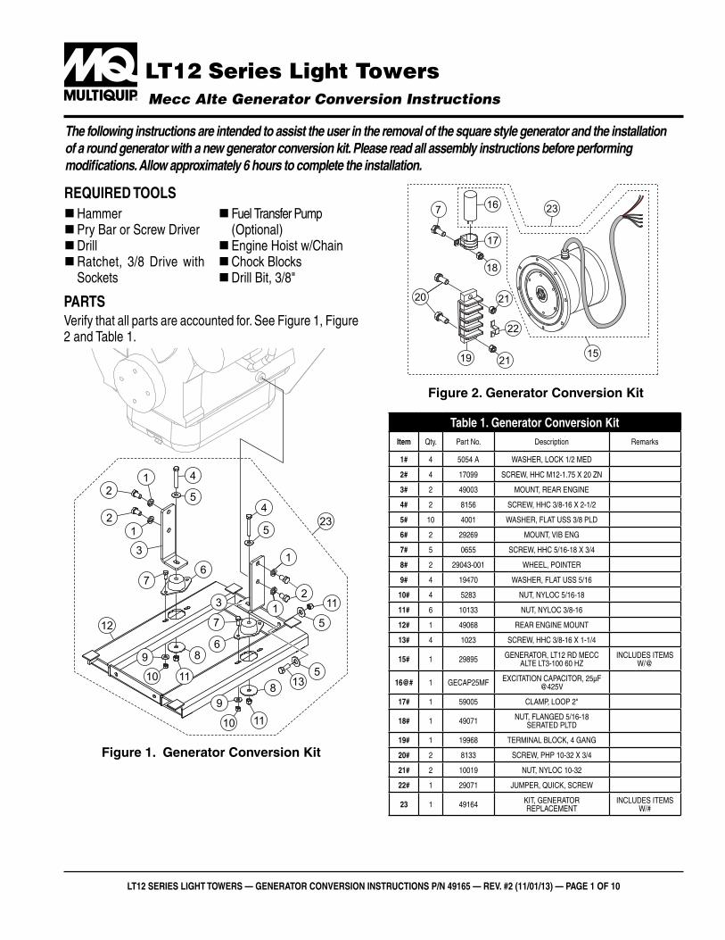
The following instructions are intended to assist the user in the removal of the square style generator and the installation of a round generator with a new generator conversion kit. Please read all assembly instructions before performing modifications. Allow approximately 6 hours to complete the installation.
required TooLs �Hammer �Pry Bar or Screw Driver �Drill �Ratchet, 3/8 Drive with Sockets
� Fuel Transfer Pump (Optional) �Engine Hoist w/Chain �Chock Blocks �Drill Bit, 3/8"
parTsVerify that all parts are accounted for. See Figure 1, Figure 2 and Table 1.
Figure 1. Generator Conversion Kit
1
1
2
2
2
3
3
4
45
6
6
7
7
8
8
9
10
9
5
1
1
10
11
11
12
135
5
11
23
Figure 2. Generator Conversion Kit
15
2316
17
7
18
19
20
21
21
22
Table 1. generator conversion Kititem Qty. Part No. Description Remarks
1# 4 5054 A WASHER, LOCK 1/2 MED
2# 4 17099 SCREW, HHC M12-1.75 X 20 ZN
3# 2 49003 MOUNT, REAR ENGINE
4# 2 8156 SCREW, HHC 3/8-16 X 2-1/2
5# 10 4001 WASHER, FLAT USS 3/8 PLD
6# 2 29269 MOUNT, VIB ENG
7# 5 0655 SCREW, HHC 5/16-18 X 3/4
8# 2 29043-001 WHEEL, POINTER
9# 4 19470 WASHER, FLAT USS 5/16
10# 4 5283 NUT, NYLOC 5/16-18
11# 6 10133 NUT, NYLOC 3/8-16
12# 1 49068 REAR ENGINE MOUNT
13# 4 1023 SCREW, HHC 3/8-16 X 1-1/4
15# 1 29895 GENERATOR, LT12 RD MECC ALTE LT3-100 60 HZ
INCLUDES ITEMS W/@
16@# 1 GECAP25MF EXCITATION CAPACITOR, 25µF @425V
17# 1 59005 CLAMP, LOOP 2"
18# 1 49071 NUT, FLANGED 5/16-18 SERATED PLTD
19# 1 19968 TERMINAL BLOCK, 4 GANG
20# 2 8133 SCREW, PHP 10-32 X 3/4
21# 2 10019 NUT, NYLOC 10-32
22# 1 29071 JUMPER, QUICK, SCREW
23 1 49164 KIT, GENERATOR REPLACEMENT
INCLUDES ITEMS W/#
LT12 series LighT Towers — generaTor conversion insTrucTions p/n 49165 — rev. #2 (11/01/13) — page 2 of 10
worK safeLY!Only a qualified service technician with proper training should perform this installation. If you need assistance with this installation, contact Multiquip for the location of its nearest ASC. Follow all shop safety rules when performing this installation.
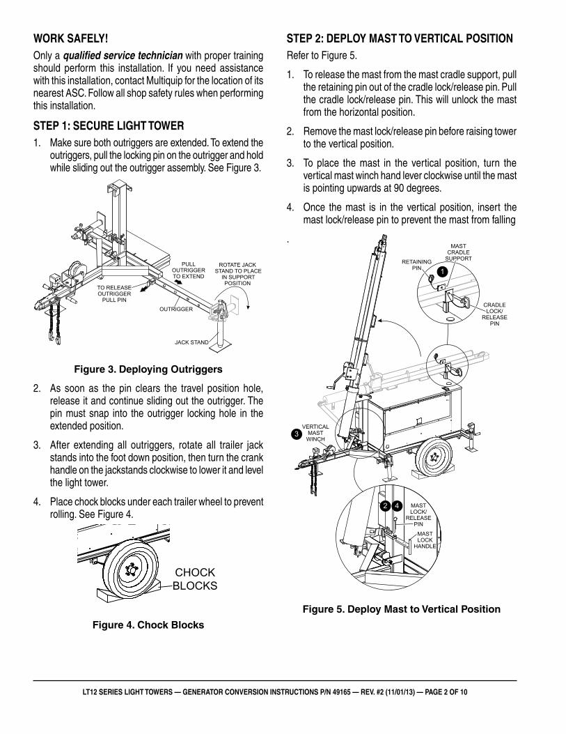
sTep 1: secure LighT Tower1. Make sure both outriggers are extended. To extend the
outriggers, pull the locking pin on the outrigger and hold while sliding out the outrigger assembly. See Figure 3.
Figure 3. Deploying Outriggers
2. As soon as the pin clears the travel position hole, release it and continue sliding out the outrigger. The pin must snap into the outrigger locking hole in the extended position.
3. After extending all outriggers, rotate all trailer jack stands into the foot down position, then turn the crank handle on the jackstands clockwise to lower it and level the light tower.
4. Place chock blocks under each trailer wheel to prevent rolling. See Figure 4.
Figure 4. Chock Blocks
TO RELEASEOUTRIGGER
PULL PIN
PULLOUTRIGGERTO EXTEND
OUTRIGGER
ROTATE JACKSTAND TO PLACE
IN SUPPORTPOSITION
JACK STAND
CHOCKBLOCKS
sTep 2: depLoY masT To verTicaL posiTionRefer to Figure 5.
1. To release the mast from the mast cradle support, pull the retaining pin out of the cradle lock/release pin. Pull the cradle lock/release pin. This will unlock the mast from the horizontal position.
2. Remove the mast lock/release pin before raising tower to the vertical position.
3. To place the mast in the vertical position, turn the vertical mast winch hand lever clockwise until the mast is pointing upwards at 90 degrees.
4. Once the mast is in the vertical position, insert the mast lock/release pin to prevent the mast from falling
.
Figure 5. Deploy Mast to Vertical Position
MASTCRADLE
SUPPORTRETAININGPIN
CRADLELOCK/
RELEASEPIN
MASTLOCK/
RELEASEPIN
MASTLOCK
HANDLE
VERTICALMAST
WINCH
1
42
3
LT12 series LighT Towers — generaTor conversion insTrucTions p/n 49165 — rev. #2 (11/01/13) — page 3 of 10
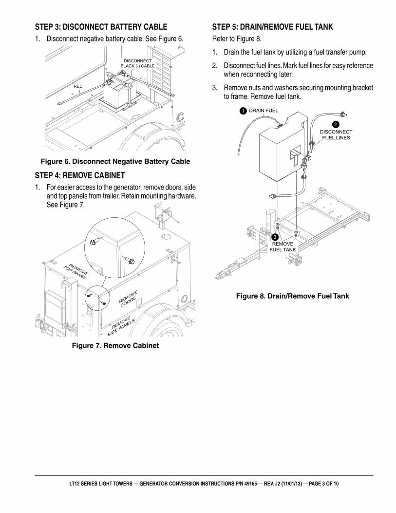
sTep 3: disconnecT baTTerY cabLe1. Disconnect negative battery cable. See Figure 6.
Figure 6. Disconnect Negative Battery Cable
sTep 4: remove cabineT1. For easier access to the generator, remove doors, side
and top panels from trailer. Retain mounting hardware. See Figure 7.
Figure 7. Remove Cabinet
RED
DISCONNECTBLACK (-) CABLE
REMOVE
TOP PANEL
REMOVE
DOORS
REMOVE
SIDE PANELS
sTep 5: drain/remove fueL TanKRefer to Figure 8.
1. Drain the fuel tank by utilizing a fuel transfer pump.
2. Disconnect fuel lines. Mark fuel lines for easy reference when reconnecting later.
3. Remove nuts and washers securing mounting bracket to frame. Remove fuel tank.
Figure 8. Drain/Remove Fuel Tank
DRAIN FUEL
DISCONNECTFUEL LINES
REMOVEFUEL TANK
1
2
3
LT12 series LighT Towers — generaTor conversion insTrucTions p/n 49165 — rev. #2 (11/01/13) — page 4 of 10
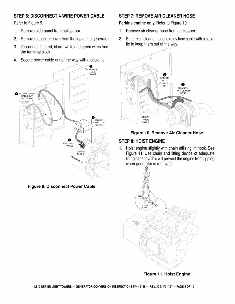
sTep 6: disconnecT 4-wire power cabLeRefer to Figure 9.
1. Remove side panel from ballast box.
2. Remove capacitor cover from the top of the generator.
3. Disconnect the red, black, white and green wires from the terminal block.
4. Secure power cable out of the way with a cable tie.
Figure 9. Disconnect Power Cable
REMOVECAPACITOR
COVER
REMOVESIDE
PANEL
DISCONNECTWIRES
1
3
2
SECURE POWERCABLE OUT OF THE WAY
4
GENERATOR
TERMINALBLOCK
sTep 7: remove air cLeaner hoseperkins engine only. Refer to Figure 10.
1. Remove air cleaner hose from air cleaner.
2. Secure air cleaner hose to relay fuse cable with a cable tie to keep them out of the way.
Figure 10. Remove Air Cleaner Hose
sTep 8: hoisT engine1. Hoist engine slightly with chain utilizing lift hook. See
Figure 11. Use chain and lifting device of adequate lifting capacity.This will prevent the engine from tipping when generator is removed.
Figure 11. Hoist Engine
REMOVEAIR CLEANER
HOSE
1
2SECURE
WITH CABLE
TIE
RELAYFUSE
CABLE
LIFTINGHOOK
LT12 series LighT Towers — generaTor conversion insTrucTions p/n 49165 — rev. #2 (11/01/13) — page 5 of 10
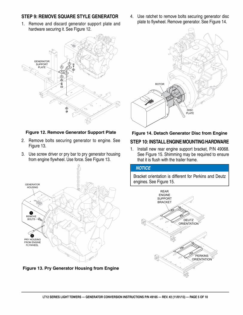
sTep 9: remove square sTYLe generaTor1. Remove and discard generator support plate and
hardware securing it. See Figure 12.
Figure 12. Remove Generator Support Plate
2. Remove bolts securing generator to engine. See Figure 13.
3. Use screw driver or pry bar to pry generator housing from engine flywheel. Use force. See Figure 13.
Figure 13. Pry Generator Housing from Engine
GENERATORSUPPORT
PLATE
1
2
REMOVEBOLTS
GENERATORHOUSING
PRY HOUSINGFROM ENGINE
FLYWHEEL
4. Use ratchet to remove bolts securing generator disc plate to flywheel. Remove generator. See Figure 14.
Figure 14. Detach Generator Disc from Engine
sTep 10: insTaLL engine mounTing hardware1. Install new rear engine support bracket, P/N 49068.
See Figure 15. Shimming may be required to ensure that it is flush with the trailer frame.
Figure 15. Install Rear Engine Support Bracket
DISCPLATE
ROTOR
NOTICE
Bracket orientation is different for Perkins and Deutz engines. See Figure 15.
REARENGINE
SUPPORTBRACKET
DEUTZORIENTATION
PERKINSORIENTATION
LT12 series LighT Towers — generaTor conversion insTrucTions p/n 49165 — rev. #2 (11/01/13) — page 6 of 10
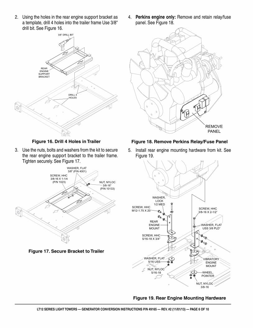
2. Using the holes in the rear engine support bracket as a template, drill 4 holes into the trailer frame Use 3/8" drill bit. See Figure 16.
Figure 16. Drill 4 Holes in Trailer
3. Use the nuts, bolts and washers from the kit to secure the rear engine support bracket to the trailer frame. Tighten securely. See Figure 17.
Figure 17. Secure Bracket to Trailer
DRILL 4HOLES
REARENGINE
SUPPORTBRACKET
3/8” DRILL BIT
SCREW, HHC 3/8-16 X 1-1/4
(P/N 1023)
WASHER, FLAT 3/8″ (P/N 4001)
NUT, NYLOC3/8-16”
(P/N 10133)
4. perkins engine only: Remove and retain relay/fuse panel. See Figure 18.
Figure 18. Remove Perkins Relay/Fuse Panel
5. Install rear engine mounting hardware from kit. See Figure 19.
Figure 19. Rear Engine Mounting Hardware
REMOVEPANEL
REAR ENGINEMOUNT
VIBRATORYENGINEMOUNT
SCREW, HHC3/8-16 X 2-1/2”
WASHER, FLATUSS 3/8 PLD”
SCREW, HHCM12-1.75 X 20
WASHER, LOCK
1/2 MED
SCREW, HHC5/16-18 X 3/4”
WASHER, FLAT5/16 USS
NUT, NYLOC5/16-18 WHEEL,
POINTER
NUT, NYLOC3/8-16
LT12 series LighT Towers — generaTor conversion insTrucTions p/n 49165 — rev. #2 (11/01/13) — page 7 of 10
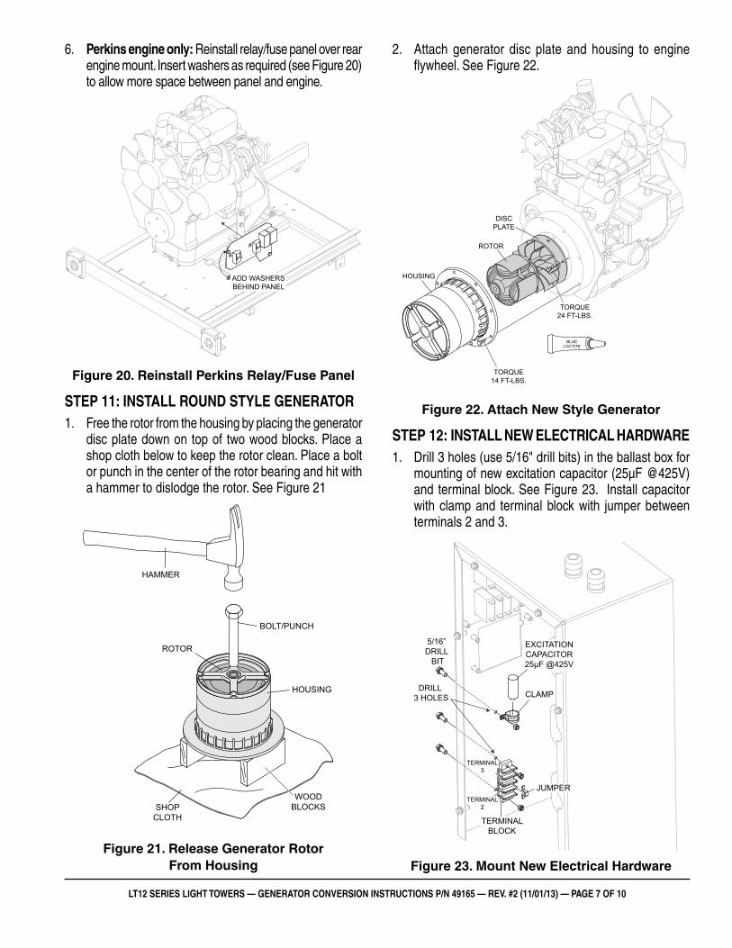
6. perkins engine only: Reinstall relay/fuse panel over rear engine mount. Insert washers as required (see Figure 20) to allow more space between panel and engine.
Figure 20. Reinstall Perkins Relay/Fuse Panel
sTep 11: insTaLL round sTYLe generaTor1. Free the rotor from the housing by placing the generator
disc plate down on top of two wood blocks. Place a shop cloth below to keep the rotor clean. Place a bolt or punch in the center of the rotor bearing and hit with a hammer to dislodge the rotor. See Figure 21
Figure 21. Release Generator Rotor From Housing
ADD WASHERSBEHIND PANEL
WOODBLOCKSSHOP
CLOTH
HAMMER
BOLT/PUNCH
HOUSING
ROTOR
2. Attach generator disc plate and housing to engine flywheel. See Figure 22.
Figure 22. Attach New Style Generator
sTep 12: insTaLL new eLecTricaL hardware1. Drill 3 holes (use 5/16" drill bits) in the ballast box for
mounting of new excitation capacitor (25µF @425V) and terminal block. See Figure 23. Install capacitor with clamp and terminal block with jumper between terminals 2 and 3.
Figure 23. Mount New Electrical Hardware
HOUSING
ROTOR
DISCPLATE
BLUELOCTITE
TORQUE14 FT-LBS.
TORQUE24 FT-LBS.
EXCITATIONCAPACITOR25µF @425V
JUMPER
TERMINALBLOCK
CLAMPDRILL
3 HOLES
5/16” DRILL
BIT
TERMINAL2
TERMINAL3
LT12 series LighT Towers — generaTor conversion insTrucTions p/n 49165 — rev. #2 (11/01/13) — page 8 of 10
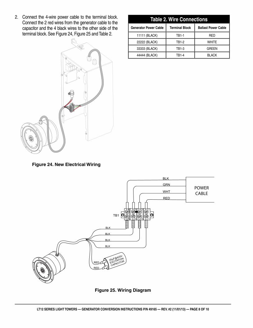
2. Connect the 4-wire power cable to the terminal block. Connect the 2 red wires from the generator cable to the capacitor and the 4 black wires to the other side of the terminal block. See Figure 24, Figure 25 and Table 2.
Figure 24. New Electrical Wiring
Table 2. wire connectionsgenerator power cable Terminal block ballast power cable
11111 (BLACK) TB1-1 RED
22222 (BLACK) TB1-2 WHITE
33333 (BLACK) TB1-3 GREEN
44444 (BLACK) TB1-4 BLACK
Figure 25. Wiring Diagram
RED
BLK
BLK
BLK
BLK
RED
RED
4444
4
3333
3
2222
2
1111
11
TB1
25µF@425V
EXCITATION
CAPACITOR
WHT
GRN
BLK
POWERCABLE
1234
1234
LT12 series LighT Towers — generaTor conversion insTrucTions p/n 49165 — rev. #2 (11/01/13) — page 9 of 10
shuTdown
1. If a load is attached to the generator of the light tower, remove the load.
2. Set the four lamp circuit breakers on the control panel to the OFF position.
3. Place the MAIN circuit breaker on the control panel to the OFF position.
4. Wait a few seconds and observe that all four lamps are OFF.
5. Let the engine idle for a few minutes with no load.
6. Turn the ignition key to the OFF position. Store key in a safe location.
7. Reassemble the cabinet.
8. Lower light tower mast and place in stow position as outlined in this manual.
9. Place outriggers in tow position, and remove chock blocks.
10. Store light tower in a clean, dry location out of the reach of children and unauthorized personnel.
emergencY shuTdown
1. Turn the ignition key to the OFF position and turn all circuit breakers to the OFF position.
NOTICE
If servicing is required, allow lamps to cool for about 15 minutes before removing lamps.
sTep 13: TesTing and reassembLY1. Reassemble the light tower in reverse order. do noT
put the cabinet back on until testing is complete.
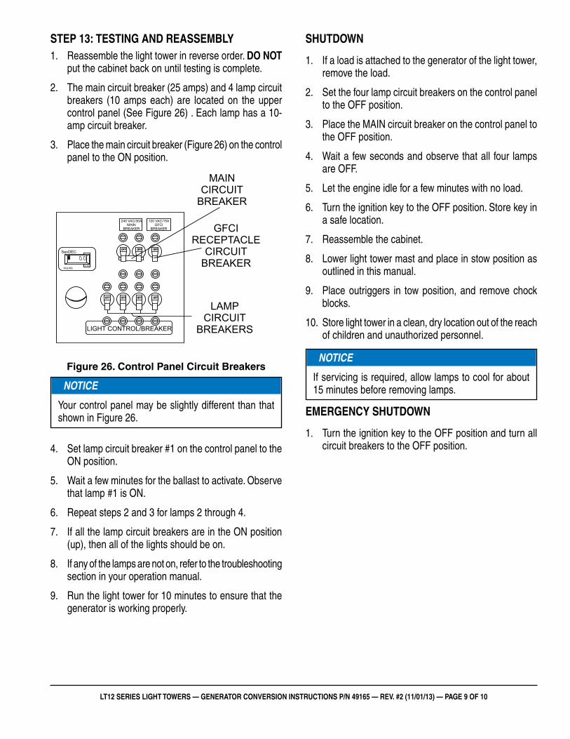
2. The main circuit breaker (25 amps) and 4 lamp circuit breakers (10 amps each) are located on the upper control panel (See Figure 26) . Each lamp has a 10-amp circuit breaker.
3. Place the main circuit breaker (Figure 26) on the control panel to the ON position.
Figure 26. Control Panel Circuit Breakers
4. Set lamp circuit breaker #1 on the control panel to the ON position.
5. Wait a few minutes for the ballast to activate. Observe that lamp #1 is ON.
6. Repeat steps 2 and 3 for lamps 2 through 4.
7. If all the lamp circuit breakers are in the ON position (up), then all of the lights should be on.
8. If any of the lamps are not on, refer to the troubleshooting section in your operation manual.
9. Run the light tower for 10 minutes to ensure that the generator is working properly.
LIGHT CONTROL/BREAKER
HOURS 1/10
0.0SenDEC
HOURS1/10
120 VAC/15AGFCI
BREAKER
240 VAC/30AMAIN
BREAKER GFCIRECEPTACLE
CIRCUITBREAKER
LAMPCIRCUIT
BREAKERS
MAINCIRCUIT
BREAKER
NOTICE
Your control panel may be slightly different than that shown in Figure 26.
lt12 series light tower mecc alte generator conversion instrUctions
Your Local Dealer is:
HERE’S HOW TO GET HELPPLEASE HAVE THE MODEL AND SERIAL
NUMBER ON-HAND WHEN CALLING
© COPYRIGHT 2013, MULTIQUIP INC.
Multiquip Inc, the MQ logo are registered trademarks of Multiquip Inc. and may not be used, reproduced, or altered without written permission. All other trademarks are the property of their respective owners and used with permission.
This manual MUsT accompany the equipment at all times. This manual is considered a permanent part of the equipment and should remain with the unit if resold.
The information and specifications included in this publication were in effect at the time of approval for printing. Illustrations, descriptions, references and technical data contained in this manual are for guidance only and may not be considered as binding. Multiquip Inc. reserves the right to discontinue or change specifications, design or the information published in this publication at any time without notice and without incurring any obligations.
UNITED STATES Multiquip Corporate Offi ce MQ Parts Department
18910 Wilmington Ave.Carson, CA 90746 Contact : [email protected]
Tel. (800) 421-1244Fax (310) 537-3927
800-427-1244310-537-3700
Fax: 800-672-7877Fax: 310-637-3284
Service Department Warranty Department
800-421-1244310-537-3700
Fax: 310-537-4259 800-421-1244310-537-3700
Fax: 310-943-2249
Technical Assistance
800-478-1244 Fax: 310-943-2238
CANADA UNITED KINGDOM
Multiquip Multiquip (UK) Limited Head Offi ce
4110 Industriel Boul.Laval, Quebec, Canada H7L 6V3 Contact : [email protected]
Tel: (450) 625-2244Tel: (877) 963-4411Fax: (450) 625-8664
Unit 2, Northpoint Industrial Estate, Globe Lane,Dukinfi eld, Cheshire SK16 4UJ Contact : [email protected]
Tel: 0161 339 2223Fax: 0161 339 3226
p/n: 49165
Related Documents


