LT Watermakers LT 400-1800 GPD Installation, Operation & Maintenance Village Marine LT-800 Part Number: 95-0021

Welcome message from author
This document is posted to help you gain knowledge. Please leave a comment to let me know what you think about it! Share it to your friends and learn new things together.
Transcript

LT Watermakers LT 400-1800 GPD
Installation, Operation & Maintenance
Village Marine LT-800
Part Number: 95-0021

i
The following are the types of flags used in this technical manual. They designate safetyrelated items and important operational instructions and should be given special attentionwhen they appear in the text:
Text formatted in this manner concerns an operating procedure or practicethat, if not strictly observed, can result in injury to personnel or loss of life.
Text formatted in this manner concerns an operating procedure or practicethat, if not strictly observed, can result in damage to or destruction ofequipment.
Text formatted in this manner concerns an operating procedure orcondition that warrants special attention
MODEL: __________________________________
SERIAL NUMBER: __________________________
DATE OF PURCHASE: ______________________
PURCHASED FROM: _________________________________
INVOICE #: __________________________________________
VESSEL NAME: ______________________________________
INSTALLED BY: ______________________________________
DATE OF INITIAL STARTUP: ____________________________
WARNING
CAUTION
NOTE

Practical and Reliable Fresh Water SupplyThe LT desalinator offers fresh water independence for ocean crossings, extended voyages or fishing where dock water supplies are unreliable.
The units feature a semi modular frame format, for installation flexibility. The frame is compact and can be above or below the water line. The boost pump and prefilters are supplied as loose items.
LT Watermakers400 - 1800 GPD(1.5 - 6.8 m3/day)
Contact Information:Parker Hannifin CorporationRacor Division/Village Marine Tec.2630 E. El Presidio StreetCarson, CA 90810
phone 310 516 9911fax 310 538 [email protected]/racor
Models 400 and 600 can be configured with membranes mounted on top or back of frame, or with remote membrane rack extending height or depth by 4”/10cm. Please specify when ordering. Other models have remote membrane rack only.
Optional Remote with water quality indicator, comes with 50 ft. cable.P/N 90-0119 60 HzP/N 90-5126 50 Hz
Key Features:
Offshore Marine LT-800

• Compact stainless steel high pressure pump is resistant to the corrosive seawater environment
• Sediment prefilter at 5 micron rating
•
• Magnetic drive low pressure pump provides up to 10 psi of boost pressure to the filtration system. Never requires seal replacement
• Glycerine filled pressure gauges
• Flowmeter to monitor freshwater production
• Freshwater flush system can be supplied for manual flushing or timed automatic flush with adjustable interval and duration for set-and-forget flushing
• 316 stainless steel pressure regulator is adjustable to allow operation in brackish or fresh water• Electrical control panel Nema
4X with motor starter and pump controls
• Automatic diversion valve diverts water to overboard if quality drops below acceptable standards
• Digital water quality monitor displays purity of product water produced
LT Watermakers400 - 1800 GPD(1.5 - 6.8 m3/day)
Standard Features:
Spares and Consumables
Model
LT-400
LT-500
LT-600
LT-800
LT-1000
LT-1300
LT-1800
Part Number
90-601690-601790-601890-602190-602290-602390-602490-602590-602690-602790-602890-6029
90-601190-6012
90-601390-601490-6073
90-601590-6074
Power**Volts/Hz/Amps
110/60/18220/60/8230/50/8
110/60/18220/60/8230/50/8
110/60/18220/60/8230/50/8
110/60/18220/60/9220/50/8
220/60/12230/50/12.5
220/60/12230/50/12.5
440/60/6
220/60/12440/60/6
CapacityGPH/LPH
16/63
21/80
25/95
33/126
42/157
54/205
75/284
Weightlbs/kg
115/52
115/52
121/55
125/57
135/61
142/64
157/71
Dimensionsinch/cm
*width 19.5/50depth 16/41height 12/30
400 size plus remote membrane rack, W x H
50x6/127x15
*width 19.5/50depth 16/41height 12/30
400 size plus remote membrane rack, W x H
50x6/127x15
400 size plus remote membrane rack, W x H
50x12/127x30
400 size plus remote membrane rack, W x H
50x18/127x45
400 size plus remote membrane rack, W x H
50x22/127x50
Part No. Description85-0050 Pump Oil, Quart33-0117 Prefilter 5 mic (models 400-800)33-0052 Prefilter 5 mic (models 1000-180033-0271 Prefilter O-ring (5 mic models 1000-1800)33-0311 Flush Filter Element90-0005 Filter O-Ring
Part No. Description40-0241 Salinity Probe33-2519 Membrane Element (model 400,600)33-0238 Membrane Element (model 500,800,1300,1800)90-2512 Membrane O-Ring Kit85-0102 Cleaning Kit85-0103 Preservation Kit
Print Reorder Number 7935 Rev-F 04-29-2013© 2013 Parker Hannifin Corporation
To maintain peak performance always use genuine Parker-Racor/Village Marine Tec. replacement parts.We reserve the right to change our specifications or standards without notice.
* Models 400 and 600 membrane rack can be mounted on top or on back of frame, add 4”/10cm to height or depth.**Only 1300 and 1800 models are available for 3 phase power. Extra transformer box included.

LT-400 to LT-1800 Manual 1 Revised 03/2010
The Offshore Marine Labs (OML) LT series Seawater Desalinator is a single-passpurification system that uses reverse osmosis (RO) to produce potable water fromseawater. Product water with salt concentrations of < 500 ppm are achieved byremoving approximately 99% of the dissolved salt in seawater.
INSTALLATION
The RO unit should be installed in a dry, sheltered location protected from directweather. Drainage should be provided beneath the RO unit to allow standing water todrain when performing maintenance or repair.
Refer to the Plumbing Diagram for arrangement and connection hose sizes. Allconnections up to and including the boost pump must be below water line. On manualflush units, the three way flushing valve may be disconnected from the flushing filter, ifnecessary to get the valve below waterline. On automatic flush units, install the“snorkel” check valve assembly below waterline. The prefilter, the main unit and themembrane rack can all be above waterline as indicated in the diagram below.
Installation Diagram
Raw water inlet, 3/4” through-hullwith sea cock, low as practical andtowards the back of the boat, butforward of the drive. Planing hullsmay need a forward facing scoopif the watermaker operates while
the vessel is underway.
Reject dischargeline overboard andabove water line.
It is important that the product water line isconnected to the top of the storage tank to prevent
chlorinated water from siphoning back into thewatermaker.
Boost pump below water linewith flooded suction.
LT-400 to LT-1800 Manual 2 Revised 03/2010
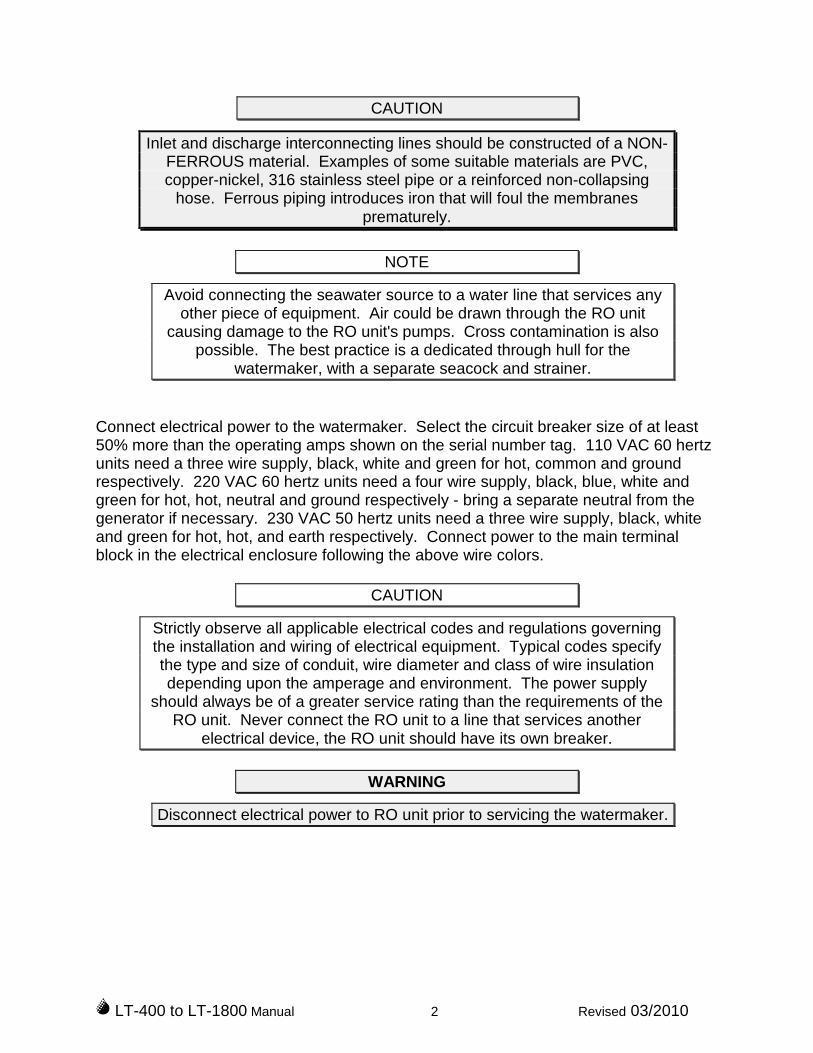
CAUTION
Inlet and discharge interconnecting lines should be constructed of a NON-FERROUS material. Examples of some suitable materials are PVC,copper-nickel, 316 stainless steel pipe or a reinforced non-collapsing
hose. Ferrous piping introduces iron that will foul the membranesprematurely.
NOTE
Avoid connecting the seawater source to a water line that services anyother piece of equipment. Air could be drawn through the RO unit
causing damage to the RO unit's pumps. Cross contamination is alsopossible. The best practice is a dedicated through hull for the
watermaker, with a separate seacock and strainer.
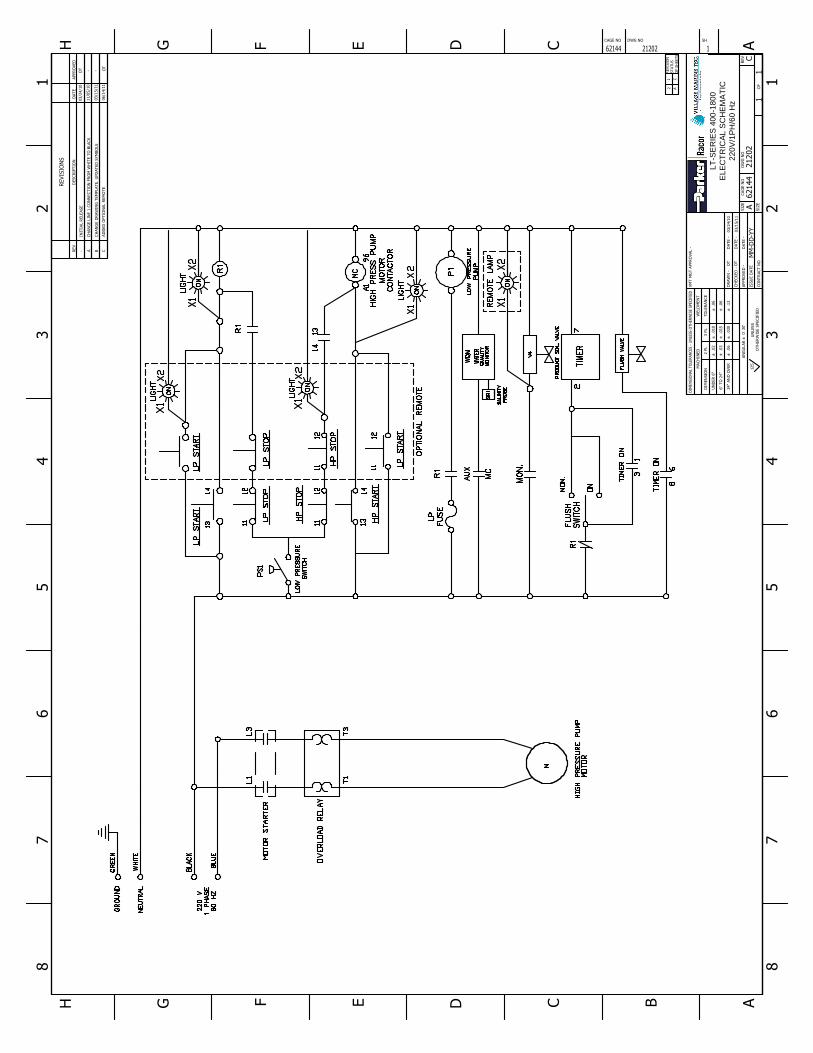
Connect electrical power to the watermaker. Select the circuit breaker size of at least50% more than the operating amps shown on the serial number tag. 110 VAC 60 hertzunits need a three wire supply, black, white and green for hot, common and groundrespectively. 220 VAC 60 hertz units need a four wire supply, black, blue, white andgreen for hot, hot, neutral and ground respectively - bring a separate neutral from thegenerator if necessary. 230 VAC 50 hertz units need a three wire supply, black, whiteand green for hot, hot, and earth respectively. Connect power to the main terminalblock in the electrical enclosure following the above wire colors.
CAUTION
Strictly observe all applicable electrical codes and regulations governingthe installation and wiring of electrical equipment. Typical codes specifythe type and size of conduit, wire diameter and class of wire insulationdepending upon the amperage and environment. The power supply
should always be of a greater service rating than the requirements of theRO unit. Never connect the RO unit to a line that services another
electrical device, the RO unit should have its own breaker.
WARNING
Disconnect electrical power to RO unit prior to servicing the watermaker.

LT-400 to LT-1800 Manual 3 Revised 03/2010
STARTUP AND OPERATING PROCEDURE
1) Check the HP pump oil level by observing sight gauge located on the pump.Open the raw saltwater supply to the unit at the through-hull. On manual flushunits, also ensure that the flushing valve is in the saltwater position with the valvehandle pointing away from the carbon flushing filter.
2) Verify the bypass valve (black handle) is open, counterclockwise.
3) Start the LP pump, verify the filter pressure gauge shows > 5 psi indicating thesystem is primed with water.
4) Start the HP pump. Water should now be flowing through the system anddischarging through the overboard reject line.
5) Slowly close the bypass valve, and confirm that the membrane pressure gaugeregisters 800 psi. The high pressure setting can be adjusted by the allen screwon the high pressure regulator behind the instrument panel.
6) Check the salinity reading, on the water monitor. Normal saltwater startupconditions produce salty water for the first 2 or 3 minutes. Then the monitorshould show lower values, drinking water quality is commonly accepted as below500. When the quality is below 500, the product solenoid valve will automaticallyopen, and start fresh water supply through the flowmeter and to the storage tank.
7) Now would be a good opportunity to make an operation log of the pressures, flowand salinity.
8) For shutdown, reverse the steps. First open the black bypass valve. Then shutdown the HP and LP pumps. If you are unsure if the watermaker will berestarted in a day or so, now is time to flush the watermaker to keep themembranes fresh while idle, please see the next section. Bacteria and biologicgrowth increases the longer stagnant water is in contact with the membranes, sothe flushing is advised whenever the unit will be idle. Once flushed, the flushshould be repeated once every one or two weeks if the idle period continues.For extended periods, see the section on pickling or preserving the watermaker.

LT-400 to LT-1800 Manual 4 Revised 03/2010
FRESH WATER FLUSH PROCEDURE – MANUAL FLUSH UNITS
Make sure the black bypass valve is open (counter clockwise), and then turn the threeway flushing valve so the handle is pointing towards the carbon flushing filter. Thecarbon filter scrubs chlorine that might be in your tank water, so the membranes are notexposed to any chlorine. Now fresh water is running through the system, you can startthe pumps and run for two minutes. After two minutes, stop the pumps and turn theflushing valve back so the handle is pointing away from the flushing filter.
FRESH WATER FLUSH PROCEDURE – AUTOMATIC FLUSH UNITS
Make sure the black bypass valve is open, counter clockwise. Also, make sure theisolation valve upstream of the carbon filter housing is open. The automatic flush switchcan be turned toward the left to complete one flush only. The electric flushing valve willopen and send fresh water through the system for the preset ON interval. Thewatermaker pumps will not run during the automatic flush. To interrupt the flush while itis underway, start and stop the LP pump.
Turning the Flush switch to the right will flush immediately, and continue with one flushcycle for each preset interval time. For the timed flush to work properly, the valves mustremain set as above. Also, the onboard fresh water distribution system must remainpressurized and power must remain supplied to the watermaker for the timer. Seawatersupply at the seacock may be open or closed for flushing.
WARNING
Leaving water systems pressurized and powered while no one is aboardthe boat has certain risks in the event of the hose failure or system
malfunction. Be sure the boat owner has reviewed and accepted theserisks when choosing to use the timed automatic flush unattended. Never
set the timed flush when pressurized water source is from dock watersupply, as the possible spill from a leaking connection is unlimited.
The timer settings for flush duration (ON time) and interval (OFF time) can be adjustedon the timer face inside the control box. In the lower left corner, set the range selectorto 30. In the top right corner, set the OFF interval multiplier to 10hours. In the bottomright corner, set the ON duration multiplier to 10seconds. Now turn the orange pointeron the dial to set the ON flushing duration, remembering that the multiplier is 10 (so setto 12 for 120 seconds flush. Turn the green pointer to set the OFF interval,remembering that the multiplier is 10 (so set to 17 for 170 hours, about one week).
Models Up to 600 800 1000 & 1300 1800ON flush duration 180 200 240 300
Set orange pointer to 18 20 24 30
Recommended ON duration, in seconds, based on fresh water pressure onboard
LT-400 to LT-1800 Manual 5 Revised 03/2010
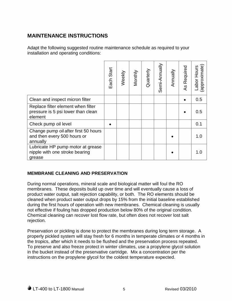
MAINTENANCE INSTRUCTIONS
Adapt the following suggested routine maintenance schedule as required to yourinstallation and operating conditions:
Ea
ch
Sta
rt
We
ekly
Mo
nth
ly
Qu
art
erly
Se
mi-A
nn
ua
lly
An
nua
lly
As
Re
qu
ired
La
bo
rH
ou
rs(a
pp
roxim
ate
)
Clean and inspect micron filter 0.5
Replace filter element when filterpressure is 5 psi lower than cleanelement
0.5
Check pump oil level 0.1
Change pump oil after first 50 hoursand then every 500 hours orannually
1.0
Lubricate HP pump motor at greasenipple with one stroke bearinggrease
1.0
MEMBRANE CLEANING AND PRESERVATION
During normal operations, mineral scale and biological matter will foul the ROmembranes. These deposits build up over time and will eventually cause a loss ofproduct water output, salt rejection capability, or both. The RO elements should becleaned when product water output drops by 15% from the initial baseline establishedduring the first hours of operation with new membranes. Chemical cleaning is usuallynot effective if fouling has dropped production below 80% of the original condition.Chemical cleaning can recover lost flow rate, but often does not recover lost saltrejection.
Preservation or pickling is done to protect the membranes during long term storage. Aproperly pickled system will stay fresh for 6 months in temperate climates or 4 months inthe tropics, after which it needs to be flushed and the preservation process repeated.To preserve and also freeze protect in winter climates, use a propylene glycol solutionin the bucket instead of the preservative cartridge. Mix a concentration per theinstructions on the propylene glycol for the coldest temperature expected.
LT-400 to LT-1800 Manual 6 Revised 03/2010
The basic procedure for all cleaning and preservative treatments is the same - a specificchemical solution is circulated through the system for 20 minutes and then flushed out.Cleaner #1 is an alkaline detergent is used to remove biological matter and grime fromthe surface of the RO membranes. Cleaner #2 is an acid cleaner is used to removemineral scale deposits. Use #1 first. The preservative or pickling chemical is labeled asChemical #3. The chemicals are conveniently available as cartridges p/n 85-0102 and85-0103 (see the filter bulletin at the back of the manual). The 2.5” diameter cartridgesfit into both 2.5” and 5” filter housings, however take extra care to make sure they stayvertical in the 5” housings when the bowl is tightened.
Use the following procedure for cleaning or preservation:
1) Flush the watermaker, so that the chemical works in fresh water not saltwater.
2) Remove the 5 micron filter, and replace with the appropriate cartridge. Whenscrewing the filter bowl back in place top up with water to minimize the air inside.
3) Place a 5 gallon bucket ½ full of fresh water near the watermaker. Connect atemporary hose from the reject outlet at the watermaker to the bucket. Connecta temporary hose from the inlet of the LP pump to the bucket.
4) Make sure the black bypass valve is open, counter clockwise. Turn the over-rideslide switch on the water monitor to OFF.
5) Start the LP boost pump. Make sure the LP pump catches prime (by raising thebucket, or by temporarily lifting the inlet hose). Once primed, you will see waterreturning to the bucket.
6) Start the HP pump and run for 20 minutes. Then turn off both pumps.
7) If you are preserving, you are done. Reconnect the regular hoses to rejectoverboard and the LP pump inlet. On the initial restart after preservation, run theunit for 10 minutes prior to switching the water monitor slide switch back to autoto clear all the preservative from the system.
8) If you have just finished circulating cleaner #1, reconnect the regular inlet pumphose, and flush the watermaker for 5 minutes. Empty the bucket as necessary.Then go back to step 1 and repeat with cleaner #2.
9) If you have just finished circulating cleaner #2, reinstall the regular 5 micron filterelement and reconnect the regular hoses. Flush the watermaker for 5 minutes toclear out the chemical. Reset the slide switch on the water monitor to AUTO.Run the watermaker with seawater and record the performance in your log todetermine the effectiveness of the cleaning.
LT-400 to LT-1800 Manual 7 Revised 03/2010
If chemical cartridges are not available, then powder chemical can be used dissolved inthe bucket (leave the regular 5 micron filter in place during cleaning).
Models up to 800 GPD Models 1000 GPD and up
Cleaner #1, p/n 85-0036 400 grams 600 grams
Cleaner #2, p/n 85-0037 400 grams 500 grams
Preservative #3, p/n 85-0038 150 grams 200 grams
Chemical Requirements when Powder is Used
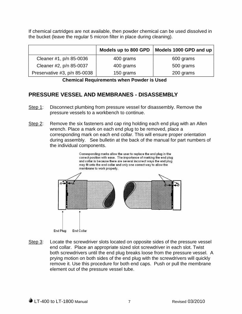
PRESSURE VESSEL AND MEMBRANES - DISASSEMBLY
Step 1: Disconnect plumbing from pressure vessel for disassembly. Remove thepressure vessels to a workbench to continue.
Step 2: Remove the six fasteners and cap ring holding each end plug with an Allenwrench. Place a mark on each end plug to be removed, place acorresponding mark on each end collar. This will ensure proper orientationduring assembly. See bulletin at the back of the manual for part numbers ofthe individual components.
Step 3: Locate the screwdriver slots located on opposite sides of the pressure vesselend collar. Place an appropriate sized slot screwdriver in each slot. Twistboth screwdrivers until the end plug breaks loose from the pressure vessel. Aprying motion on both sides of the end plug with the screwdrivers will quicklyremove it. Use this procedure for both end caps. Push or pull the membraneelement out of the pressure vessel tube.
LT-400 to LT-1800 Manual 8 Revised 03/2010
NEVER FORCE A MEMBRANE OUT OF A PRESSURE VESSEL BYAPPLYING PRESSURE ON THE PRODUCT WATER TUBE (CENTERTUBE), AS THIS WILL DAMAGE THE MEMBRANE. IF MEMBRANE ISDIFFICULT TO REMOVE, USE A 2” DIAMETER PLASTIC PIPE (PVC)TO APPLY PRESSURE ON THE PROTECTED END OF THEMEMBRANE.
Step 4: Note which end of the pressure vessel the brine seal was installed at. Thebrine seal is a black u-cup seal on the membrane outer diameter near oneend. This is the feed end of the pressure vessel. When reinstalling the ROmembrane the brine seal must be located at the feed end of the pressurevessel.
PRESSURE VESSEL AND MEMBRANES - REASSEMBLY
Step 1: Inspect all O-Rings; product O-Rings, end plug O-Rings, and Brine seal.Replace seals if there is visible damage. The product water O-Rings areinternal O-Rings, inside the center hole in the end cap.
Step 2: Lubricate O-Rings and entrances to pressure vessel with glycerin or siliconelubricant. Locate discharge end of pressure vessel. Install discharge endplug by lining up with the holes of the pressure vessel, paying attention to thereference mark. Position end cap ring and insert fasteners by hand.
NEVER USE ANY TYPE OF LUBRICANT CONTAINING PETROLEUMOIL. OIL CAN DAMAGE YOUR UNIT AND REDUCE MEMBRANESPERFORMANCE.
Step 3: Align the membrane so the end without the brine seal enters the feed end ofthe pressure vessel first. Slide membrane into pressure vessel untilresistance is felt. Continue applying pressure until the product water tube sitsinto the end plug.
Step 4: Install the remaining end plug (align end plug holes with mounting holesproperly), use the reference mark made in step 2 for correct assembly.Tighten the six fasteners for each end cap. Install the vessels and reconnectplumbing.
NOTE: Do not apply Teflon tape or sealant to straight thread fittings such asthose used on High Pressure Hose ends.

LT-400 to LT-1800 Manual 10 Revised 03/2010
OPERATION LOG
We encourage operators to keep a simple operation log for the watermaker. Evenoccasional entries will help in troubleshooting. It is especially important to recordperformance after the first 3 hours after installation so the baseline is known.
Date FilterPressure
MembranePressure
ProductFlow
WaterQualityTDS
(ppm)
WaterTemp, Comments

AKB2698
Line
AKB2698
TextBox
Filter Pressure Gauge, p/n 40-0300
AKB2698
Line
AKB2698
TextBox
Membrane Pressure Gauge p/n 40-0302
AKB2698
Line
AKB2698
TextBox
Water Monitor, p/n 40-0226
AKB2698
Line
AKB2698
Line
AKB2698
TextBox
Pump Switches, p/n 20-1591 (body) 20-1592 (block 60 hz) 20-1593 (block 50 hz)
AKB2698
Line
AKB2698
TextBox
Bypass Valve, p/n 60-0064
AKB2698
TextBox
Product Flowmeter Models 400, 500, 600 p/n 40-1006 Models 800, 1000, 1300, p/n 40-1018 Model 1800, p/n 40-0240
AKB2698
Line
AKB2698
TextBox
Optional Flush Switch (not shown) p/n 20-3029
AKB2698
Line
AKB2698
TextBox
Membrane Element Model 400, two 33-2519 Model 500, one 33-0238 Model 600, three 33-2519 Model 800, two 33-0238 Model 1000, two 33-0238 Model 1300, three 33-0238 Model 1800, four 33-0238
AKB2698
Line
AKB2698
TextBox
See bulletin for Pressure Vessel Parts, back of manual
AKB2698
TextBox
PARTS DIAGRAM - SEE ALSO SPARES LIST AT FRONT OF MANUAL
AKB2698
Line
AKB2698
Oval
AKB2698
Oval
AKB2698
TextBox
LP Pump Fuse Models 400 to 800, p/n 20-0621 Models 1000 & up, 60 hz, p/n 20-0619 Models 1000 & up, 50 hz, p/n 20-0620
AKB2698
Line

AKB2698
Stamp
AKB2698
Text Box
PARTS DIAGRAM - SEE ALSO SPARES LIST AT FRONT OF MANUAL
AKB2698
Text Box
Product Solenoid Valve Models up to 800, 60 Hz, p/n 19-1124 Models up to 800, 50 hz, p/n 19-2124 Models 1000 & up, 60 hz, p/n 19-1131 Models 1000 & up, 50 hz, p/n 60-0162
AKB2698
Text Box
Low Pressure Switch, p/n 20-0280
AKB2698
Text Box
Pressure Regulator, p/n 60-4547
AKB2698
Text Box
Inlet water, from 5 micron filter
AKB2698
Text Box
HP Pump Models up to 600, p/n 70-1253 Model 800, p/n 70-1255 Models 1000 & 1300 at 50 hz, p/n 70-1254 Models 1000 & 1300 at 60 hz, p/n 70-1256 Model 1800 Pump, p/n 70-1254 Pumps 70-1253/5/6, HP Pump outlet valve kit, p/n 70-6135 Pumps 70-1253/5/6, HP Pump inlet valve kit, p/n 70-6136 Pumps 70-1253/5/6, HP Pump seal service kit, p/n 70-6134 Pump 70-1254 only, HP Pump outlet valve kit, p/n 70-6138 Pump 70-1254 only, HP Pump inlet valve kit, p/n 70-6139 Pump 70-1254 only, HP Pump seal service kit, p/n 70-6137
AKB2698
Text Box
LP Pump (not shown) Models up to 800 at 60 hz, p/n 70-7504, pump repair kit p/n 70-7506 Models up to 800 at 50 hz, p/n 70-7505, pump repair kit p/n 70-7506 Models 1000 and up, p/n 70-1550, pump repair kit p/n 90-0617
AKB2698
Text Box
Pump Oil, p/n 85-0050
AKB2698
Text Box
Salinity Probe p/n 40-0241
AKB2698
Text Box
Reject Brine water, to overboard
AKB2698
Text Box
Fresh Water, to tank
AKB2698
Line
AKB2698
Line
AKB2698
Line
AKB2698
Line
AKB2698
Line
AKB2698
Line
AKB2698
Line
AKB2698
Line
AKB2698
Line

AKB2698
TextBox
Overide Switch. Set to the AUTO position for normal operation. Set to OFF to keep Product Solenoid Valve closed, for instance when flushing out cleaning chemicals or for 10 minutes when first installing new membranes. Set to ON to keep Product Solenoid Valve open, for instance when it is desired to override the quality reading from the probe or for troubleshooting.
AKB2698
TextBox
Salinity display, as ppm NaCl. Display reads 1 when result is above 2000 ppm.
AKB2698
TextBox
Press the SET button to view mimium acceptable water quaility. Adust by turning the tiny potentiometer marked SET with a screwdriver. Recommended setting 500, meaning water above 500 ppm is rejected overboard.
AKB2698
TextBox
Press the MEAS button to view the measured salinity. Calibrate by putting probe in a known buffer solution, and turning the CAL potentiometer with a screwdriver.
AKB2698
TextBox
LED lamp lights yellow when water is "good" quality (below setpoint). Lamp is green when water quality is ''bad'' (above setpoint)
AKB2698
TextBox
Optional Auto Flush Switch p/n 20-3029
AKB2698
TextBox
LP Pump Fuse Models 400 to 800, p/n 20-0621 Models 1000 & up, 60 hz, p/n 20-0619 Models 1000 & up, 50 hz, p/n 20-0620
AKB2698
Line
AKB2698
Line
AKB2698
Line
AKB2698
Line
AKB2698
Line
AKB2698
Line
AKB2698
Line
AKB2698
TextBox
CONTROL & METER DETAILS

AKB2698
TextBox
Green Lamp illuminates when producing fresh water with quality within setpoint parameters
AKB2698
TextBox
Pumps can be started and stopped from the remote. For remote operation, the bypass valve (black handle) can be left in the closed, clockwise, position
AKB2698
TextBox
AKB2698
TextBox
OPTIONAL REMOTE CONTROL BOX
AKB2698
Line
AKB2698
Line
AKB2698
Line
AKB2698
TextBox
Flushing cannot be controlled from the remote, however timed flush be set at the watermaker with the optional auto-flush configuration. Flushing requires the bypass valve (black handle) to be left open, counterclockwise.

OTB2716
Line
OTB2716
Line
OTB2716
Line
OTB2716
Line
12120262144SHDWG NOCAGE NO
HH
GG
FF
EE
DD
CC B
AA
88
77
66
55
44
33
22
11
30'
~0
`A
NG
ULAR
.12
`
.06
`
.06
`
.030
`
.015
`
.010
`
.06
`
.03
`
.02
`
TO
LER
AN
CE
3PL
2PL
24"
AN
DO
VER
6"
TO
24"
UN
DER
6"
DIM
EN
SIO
N
MACH
INED
WELD
MEN
T
OF
11
SIZ
ECO
NTR
ACT
NO
125
OTH
ER
WIS
ESPEC
IFIE
DU
NLESS
DIM
EN
SIO
NAL
TO
LERAN
CES
-U
NLE
SSO
TH
ERW
ISE
SPECIF
IED
VM
TM
GT
APPR
OVAL
- DATE
-
DATE
-
MM
-DD
-YY
DATE
-
ISSU
ED
ATE
APPRO
VED
-
CH
ECKED
-
DR
AW
N-
21202
A62144
REV
DW
GN
OCA
GE
NO
SIZ
E
LT
-SE
RIE
S4
00
-18
00
EL
EC
TR
ICA
LS
CH
EM
AT
IC2
20
V/1
PH
/60
Hz
C
REVIS
ION
STATU
S
OF
SH
EETS
1 C
OT
03/2
4/1
0
REV
REVIS
ION
S
-
DESCR
IPTIO
ND
ATE
03/2
4/1
0
APPR
OVED
OT
INIT
IAL
RELEASE
A11/0
5/1
0-
CH
AN
GE
LIN
E1
CO
NN
ECTIO
NFR
OM
WH
ITE
TO
BLA
CK
2 A
BC
HAN
GE
DR
AW
ING
TEM
PLA
TE.
UPD
ATED
SYM
BO
LS03/1
5/1
1-
OT
03/1
5/1
1
CAD
DED
OPTIO
NAL
REM
OTE
06/1
4/1
1O
T

12120262144SHDWG NOCAGE NO
HH
GG
FF
EE
DD
CC B
AA
88
77
66
55
44
33
22
11
30'
~0
`AN
GU
LAR
.12
`
.06
`
.06
`
.030
`
.015
`
.010
`
.06
`
.03
`
.02
`
TO
LERAN
CE
3PL
2PL
24"
AN
DO
VER
6"
TO
24"
UN
DER
6"
DIM
EN
SIO
N
MACH
INED
WELD
MEN
T
OF
22
SIZ
ECO
NTRACT
NO
125
OTH
ERW
ISE
SPECIF
IED
UN
LESS
DIM
EN
SIO
NA
LTO
LER
AN
CES
-U
NLE
SS
OTH
ERW
ISE
SPE
CIF
IED
VM
TM
GT
APPRO
VAL
- DATE
-
DATE
-
MM
-DD
-YY
DATE
-
ISSU
ED
ATE
APPRO
VED
-
CH
ECKED
-
DRAW
N-
21202
A62144
REV
DW
GN
OCAG
EN
OSIZ
E
LT
-SE
RIE
S4
00
-18
00
ELE
CT
RIC
AL
SC
HE
MA
TIC
22
0V
/1P
H/6
0H
z
B
REVIS
ION
STATU
SO
FSH
EETS
1 C
OT
03/2
4/1
0
REV
REVIS
ION
S
-
DESCRIP
TIO
ND
ATE
03/2
4/1
0
APPRO
VED
OT
INIT
IAL
RELEASE
A03/1
5/1
1-
CH
AN
GED
DR
AW
ING
TEM
PLATE.U
PD
ATED
SYM
BO
LS
2 B
OT
03/1
5/1
1
B06/1
4/1
1O
TAD
DED
OPTIO
NAL
REM
OTE

211 2 3 4 5 6 8 9 11
13
14
15
18
19
20 1 2 3 4 5 6 7 8 9
WH
ITE
BLA
CK
BLU
E
BR
OW
N
GR
EE
N
GR
AY
OR
AN
GE
PU
RP
LE
WH
ITE
BLA
CK
RE
D
BLU
E
BR
OW
N
GR
EE
N
GR
AY
OR
AN
GE
PU
RP
LE
RE
D
REMOTETERMINALBLOCKLTTERMINALBLOCK
RE
MO
TEC
AB
LE
RE
MO
TEC
AB
LE
7 10
16
12
2.
FOR
UN
ITS
WIT
HR
EM
OTE
,R
EM
OV
EJU
MP
ER
SB
ETW
EE
N1
4-1
5A
ND
16
-17
BE
FO
RE
WIR
ING
.
LPPU
MP
1.
FOR
UN
ITS
WIT
HO
UT
RE
MO
TE,
AD
DJU
MP
ER
SB
ETW
EE
N1
4-1
5A
ND
16
-17
BE
FO
RE
WIR
ING
.
VA
LVE
LPSW
ITC
H
PR
OD
.SO
L
VA
LVE
BLA
CK
WH
ITE
BLA
CK
BLA
CK
BLA
CK
WH
ITE
WH
ITE
WH
ITE
NO
TES:
FLU
SH
17
03
/01
/12
A
8
D C B
76
NO
.R
EF
DR
AW
ING
TIT
LE
RE
FE
RE
NC
ED
RA
WIN
GS
5
G F EH
87
65
DE
TA
ILD
RA
WIN
G
WIR
ING
,RE
MO
TE
TO
CO
NT
RO
LB
OX
62
14
4
3
AN
GU
LA
R±
0°
30
'
24
"&
OV
ER
UN
DE
R2
4"
DIM
EN
SIO
N
DIM
EN
SIO
NA
LT
OL
ER
AN
CE
S-
UN
LE
SS
OT
HE
RW
ISE
SP
EC
IFIE
D
OT
HE
RW
ISE
NO
TE
D
AN
GU
LA
R±
0°
30
'
4
DW
GN
O.
12
5
24
"&
OV
ER
6"
TO
24
"
UN
DE
R6
"
DIM
EN
SIO
N
UN
LE
SS
±.0
6
±.0
3
±.0
2
±.0
30
±.0
15
±.0
10
DE
CIM
AL
S
MA
CH
INE
D
2P
L3
PL
VM
TM
GT
AP
PR
OV
AL
OT
CO
NT
RA
CT
NO
.O
TH
ER
WIS
EN
OT
ED
±.1
2
UN
LE
SS
ISS
UE
DA
TE
DR
AW
N
CH
EC
KE
D
AP
PR
OV
ED
±.0
6
TO
LE
RA
NC
E
WE
LD
ME
NT
CA
DF
ILE
NU
MB
ER
----
----
----06
/10/
11
2
DA
TE
DA
TE
DA
TE
A SC
AL
EN
ON
E
SIZ
EC
AG
EN
O
M4555
RE
VC
M4
55
5S
HE
ET
DW
GN
O
1
CO
MM
ER
CIA
LP
RO
DU
CT
SD
IVIS
ION
1O
F1
CRE
V
A
OF
SH
EE
TS
REV
CSH
1
1R
EV
ISIO
N
ST
AT
US
SH
DWG NO .CAG E NO .
6 2 1 4 4CD
DESCRIP
TIO
N
34
REV
INIT
IAL
RE
LE
AS
E-
2
EFG
06
/10
/11
DATE
REVIS
IONS
1
APPROVED
H
- -- -
--
-
Rac
or
RE
VIS
ED
JU
MP
ER
CO
NN
EC
TIO
NS
TE
CH
NO
LO
GY
08
/04
/11
AU
PD
AT
ED
WIR
ING
08
/04
/11
BA
DD
JU
MP
ER
SP
ER
PR
OD
UC
TIO
NG
A
MB
GA
09/0
2/11
09/0
2/11
C
VIL
LAG
EM
AR
INE
OT

LP
SW
ITC
H,
PN
20
-02
80
,E
LE
CT
RIC
AL
SC
HE
MA
TIC
S1
20
VA
CF
OR
ST
W/S
PW
CO
NN
EC
TIN
GT
OT
HE
LP
SW
ITC
H
GN
DN
OT
US
ED
PIN
1(C
OM
.)U
SE
D
PIN
2(N
.C
.)N
OT
US
ED
PIN
3(N
.O
.)U
SE
D
LP
SW
ITC
H
PIN
1-
CO
M.
PIN
2-
N.C
.P
IN3
-N
.O
.
GN
D
PIN
1P
IN2
PIN
3
NO
TE
:S
EE
AP
PR
OP
RIA
TE
TE
CH
NIC
AL
MA
NU
AL
FO
RT
HE
PR
OP
ER
WIR
ING
CO
NN
EC
TIO
NW
ITH
INT
HE
SP
EC
IFIC
UN
IT
QU
ICK
DIS
CO
NN
EC
T
SID
EV
IEW
BO
TT
OM
VIE
W
NO
TE
:N
OT
AC
TU
AL
RE
PR
ES
EN
TA
TIO
NO
FP
INO
RIE
NT
AT
ION
LA
BE
LO
NS
WIT
CH
G
12
3
CA
BL
ET
OU
NIT

Models 2SF05SEEL, 2SF10SEEL, 2SF15SEEL, 2SF25SEEL, 2SF29SEEL, 2SF35SEEL, 2SF42SEEL March 2010
ITEM P/N MATL DESCRIPTION MODEL USED QTY106 545192 FPM Seal, LPS w/SS-Spg All 3
546507 EPDM Seal, LPS w/SS-Spg All 3125 46652 HT Seal, Hi-Temp, 2-Pc w/S-Support 05-35SEEL 3
44936 FPM Seal, HPS w/SS 42SEEL 346667 HT* Seal, Hi-Temp, 2-Pc w/S-Support 42SEEL 3
134 33873 NY Valve, Inlet [4/02] 05-35SEEL 3152 11377 FPM O-Ring, Adapter Spacer, Inner-80D 05-35SEEL 3
46647 EPDM O-Ring, Adapter Spacer, Inner-80D 05-35SEEL 3129977 FPM O-Ring, Adapter Spacer, Inner 42SEEL 3129978 EPDM O-Ring, Adapter Spacer, Inner 42SEEL 3
159 11377 FPM O-Ring, Adapter Spacer, Outer-80D All 346647 EPDM O-Ring, Adapter Spacer, Outer-80D All 3
AKB2698
TextBox
WaterMaker Model LT-400 LT-500 LT-600 LT-800 LT-1000 LT-1300 LT-1800
AKB2698
TextBox
High Pressure Pump, Parts and Service Guide
AKB2698
TextBox
60 Hertz Power Pump ID 2SF25SEEL 2SF25SEEL 2SF25SEEL 2SF29SEEL 2SF35SEEL 2SF35SEEL 2SF42SEEL
AKB2698
TextBox
50 Hertz Power Pump ID 2SF29SEEL 2SF29SEEL 2SF29SEEL 2SF29SEEL 2SF42SEEL 2SF42SEEL Not Available

Models 2SF05SEEL, 2SF10SEEL, 2SF15SEEL, 2SF25SEEL, 2SF29SEEL, 2SF35SEEL, 2SF42SEEL March 2010
[ ] Date of latest production change. † Production parts are different than repair parts. R Components comply with RoHS Directive. *Review individual parts in each kit for material code identification.
See Tech Bulletins 002, 036, 043, 055, 064, 070, 073, 074, 091, 092 and 095 for additional information.NOTE: Discard Key that may come standard with most motors and engines and use only the key included in Bolt kit. MATERIAL CODES (Not Part of Part
Number): AL=Aluminum CC=Ceramic CM=Chrome-Moly EPDM=Ethylene proplenedienemonamer FCM=Forged Chrome-moly FPM=Fluorocarbon HT=Hi-Temp (EPDM Alternative) NBR=Medium Nitrile (Buna-N) NY=Nylon PVDF=Polyvinylidene Fluoride RTP=Reinforced Composite S=304SS SNG=Special Blend (Buna)
SS=316SS SSZZ=316SS/Zamak STL=Steel STCP=Steel/Chrome Plated STZP=Steel/Zinc Plated TNM=Special High Strength
PARTS LISTITEM P/N MATL DESCRIPTION MODEL USED QTY
15 547445 S Screw, HHC Sems (M6x14) [3/03] All 38 547153 AL Cover, Bearing [3/03] All 1
10 14041 NBR O-Ring, Bearing Cover - 70D [3/03] All 111 55337 NBR Seal, Oil, Crankshaft - 70D [3/03] All 115 14488 STL Bearing, Ball - Inner All 120 547046 TNM Rod, Connecting All 325 543135 FCM Crankshaft, 1.7mm 05SEEL 1
46109 FCM Crankshaft, 3.1mm 10SEEL 144931 FCM Crankshaft, 4.5mm 15SEEL 1544693 FCM Crankshaft, 7.3mm 25SEEL 145426 FCM Crankshaft, 8.5mm 29SEEL 1544694 FCM Crankshaft, 10.2mm 35SEEL, 42SEEL 1
26 12385 STL Ring, Retaining, Bearing All 127 15710 STL Bearing, Ball - Outer All 132 547961 RTP Cap, Oil Filler w/O-Ring All 133 14179 NBR O-Ring, Oil Filler Cap - 70D All 237 92241 – Gauge, Oil w/Gasket - 80D All 138 44428 NBR Gasket, Flat, Oil Gauge - 80D All 148 44842 NY Plug, Drain All 149 14179 NBR O-Ring, Drain Plug - 70D All 153 547285 AL Crankcase [3/03] All 164 16948 CM Pin, Crosshead All 365 544695 SSZZ Rod, Plunger All 369 126259 STCP R Washer, Oil Seal All 370 25461 NBR Seal, Oil Crankcase All 390 544697 CC Plunger, Ceramic (M18x18) 05-35SEEL 3
831290 CC Plunger, Ceramic (M20x18) 42SEEL 3100 44869 PVDF Retainer, Seal All 3106 547683 NBR Seal, LPS w/SS-Spg All 3110 547704 SS Manifold, Inlet 05-35SEEL 1
831288 SS Manifold, Inlet 42SEEL 1125 44652 SNG Seal, HPS w/SS 05-35SEEL 3
44649 SNG Seal, HPS w/SS 42SEEL 3134 543691 SS Valve, Inlet [4/02] 05-35SEEL 3
831400 SS Valve, Inlet 42SEEL 3135 543689 SS Spacer All 3136 543690 SS Spring, Inlet Valve All 3137 88575 S Washer, Conical (M6) All 3138 543692 SS Nut (M6) All 3152 † 26089 NBR O-Ring, Adapter Spacer, Inner-80D 05-35SEEL 3
549539 NBR O-Ring, Adapter Spacer, Inner 42SEEL 3157 544700 SS Adapter, Valve 05-35SEEL 3
831289 SS Adapter, Valve 42SEEL 3159 † 26089 NBR O-Ring, Adapter Spacer, Outer-80D All 3
11377 FPM O-Ring, Adapter Spacer, Outer-80D All 346647 EPDM O-Ring, Adapter Spacer, Outer-80D All 3
164 544293 SS Seat All 3166 543669 SS Valve All 3167 543700 SS Spring All 3168 44565 PVDF Retainer, Spring All 3185 547705 SS Manifold, Discharge All 1188 544701 S Screw, HSH (M8x80) All 6255 30517 STZP R Assy, Bolt Mount All 1
ITEM P/N MATL DESCRIPTION MODEL USED QTY106 545192 FPM Seal, LPS w/SS-Spg All 3
546507 EPDM Seal, LPS w/SS-Spg All 3125 46652 HT Seal, Hi-Temp, 2-Pc w/S-Support 05-35SEEL 3
44936 FPM Seal, HPS w/SS 42SEEL 346667 HT* Seal, Hi-Temp, 2-Pc w/S-Support 42SEEL 3
134 33873 NY Valve, Inlet [4/02] 05-35SEEL 3152 11377 FPM O-Ring, Adapter Spacer, Inner-80D 05-35SEEL 3
46647 EPDM O-Ring, Adapter Spacer, Inner-80D 05-35SEEL 3129977 FPM O-Ring, Adapter Spacer, Inner 42SEEL 3129978 EPDM O-Ring, Adapter Spacer, Inner 42SEEL 3
159 11377 FPM O-Ring, Adapter Spacer, Outer-80D All 346647 EPDM O-Ring, Adapter Spacer, Outer-80D All 3
OPTIONAL PARTS
STANDARD AND OPTIONAL KITS
Veiw other system accesseries on-line at http://www.catpumps.com/accessories-valves-selector-by-specification.cfm
Bold print part numbers are unique to a particular pump model.
OPTIONAL EQUIPMENT
ITEM P/N MATL DESCRIPTION MODEL USED QTY300 34973 NBR Kit, Seal (Inclds: 106, 125, 152, 159) 05-35SEEL 1
33453 FPM Kit, Seal (Inclds: 106, 125, 152, 159) 05-35SEEL 130536 EPDM Kit, Seal (Inclds: 106, 125, 152, 159) 05-35SEEL 176973 NBR Kit, Seal (Inclds: 106, 125, 152, 159) 42SEEL 176955 FPM Kit, Seal (Inclds: 106, 125, 152, 159) 42SEEL 176996 EPDM Kit, Seal (Inclds: 106, 125, 152, 159) 42SEEL 1
310 34972 NBR Kit, Valve (Inclds: 152,159,164,166,167,168) 05-35SEEL 133454 FPM Kit, Valve (Inclds: 152,159,164,166,167,168) 05-35SEEL 130546 EPDM Kit, Valve (Inclds: 152,159,164,166,167,168) 05-35SEEL 176972 NBR Kit, Valve (Inclds: 152,159,164,166,167,168) 42SEEL 176445 FPM Kit, Valve (Inclds: 152,159,164,166,167,168) 42SEEL 176446 EPDM Kit, Valve (Inclds: 152,159,164,166,167,168) 42SEEL 1
311 39668 NBR Kit, Inlet Valve w/SS-IV (Incls:134-138,152,159) 05-35SEEL 134974 NBR Kit, Inlet Valve w/NY-IV (Incls:134-138,152,159) 05-35SEEL 133460 FPM Kit, Inlet Valve w/NY-IV (Incls:134-138,152,159) 05-35SEEL 130556 EPDM Kit, Inlet Valve w/NY-IV (Incls:134-138,152,159) 42SEEL 176668 NBR Kit, Inlet Valve w/SS-IV (Incls:134-138,152,159) 42SEEL 176465 FPM Kit, Inlet Valve w/SS-IV (Incls:134-138,152,159) 42SEEL 176466 EPDM Kit, Inlet Valve w/SS-IV (Incls:134-138,152,159) 42SEEL 1
ITEM P/N MATL DESCRIPTION MODEL USED QTY283 990394 – Kit, Oil Drain 05-35SEEL 1285 80228 STL Screw (M8-1.25x80) (Motor Removal) 05-35SEEL 2352 44050 STPZ Tool, Oil Gauge Removal All 1– 6107 – Oil, Bottle (21 oz) ISO-68 Hydraulic All 1
– (Fill to specified crankcase capacity prior to start-up)– 6575 – Plunger Pump Service DVD All 1– 6119 – Lubricant, Antiseize (1 oz.) All 1

SERVICING THE VALVES
Disassembly of the Discharge Valve Assembly
1. Disconnect all plumbing and remove unloader for easein servicing.
NOTE: CEE and SEEL models do not come withstandard unloader.
2. Inspect oil for proper level, presence of water or discol-oration and replace as needed.
3. Using a standard M6 allen wrench remove the six (6)(2SF) or eight (8) (4SF) Socket Head Screws from themanifold. Remove the outer screws first, then the cen-ter screws.
4. Using a soft mallet tap the back side of the DischargeManifold from alternate sides to maintain alignmentand avoid damage to the plungers.
5. Grasp the Discharge Manifold from the from undersideand gradually lift manifold while you pull away from theCrankcase.
6. The Adapter Spacers may stay with either theDischarge or Inlet Manifold. By inserting two opposing
screwdrivers between Spacer and manifold you caneasily pry them out of the Discharge Manifold. If theystay in the Inlet Manifold, gently work them up anddown as you pull away from the Inlet Manifold.
7. The valve assemblies are in the Discharge Manifoldports and will fall out when manifold is turned over. Acomplete valve assembly includes: Retainer, Spring,Valve and Seat.
NOTE: On “X” models the Adapter and Seat areone-piece.
NOTE: The “GZ” models use the standard “SF”Valve Kit.
Removal of Discharge Manifold Removal of Adapter from Discharge Manifold Removal of Adapter from Inlet Manifold
Discharge Valve Assembly (4SF) Adapter and Discharge Valve Assembly (2SF) Inlet Valve Assembly

Reassembly of the Discharge Valve Assembly
1. Examine Adapter Spacer O-Rings and replace if worn.Lubricate and install O-Rings and Back-up-Rings onboth front and rear of the Adapter Spacer.
2. Examine the Valve Retainers for scale buildup or wearand install into each Discharge Manifold port with tabdown into the manifold chamber.
3. Replace worn or damaged Springs and place intoRetainers.
4. Examine Valve and Seats for pitting, grooves or wearand replace as needed.
5. Place Valves over Springs with concave side down.
6. Place Valve Seats on Valves with concave side down.
NOTE: On “X” Models, the Adapter and Seat areone-piece.
7. Lubricate O.D. of Adapter Spacer and insert smallerI.D. into Discharge Manifold ports. Snap into posi-tion. Exercise caution not to cut or pinch o-rings.
8. Carefully guide Discharge Manifold with Spacers overPlunger Rod ends and press into Inlet Manifold.
9. Replace Socket Head Screws and torque per chart.Use torque sequence chart.
10. If oil was not changed, be certain oil is to mark on OilGauge before resuming operation.
Removal of Inlet Manifold Removal of Lo-Pressure Seal Plunger, Seals and V-Packing Arrangement
Installation of Lo-Pressure Seals V-Packing Positioning Installation of V-Packings
2SF 4SF

SERVICING THE SEALS
Disassembly of the Seal Assembly
1. Remove the Inlet Valve Assembly from the exposedplunger rod ends, including Cotterpin, Nut, Washer,Spring, Spacer and Inlet Valve.
2. Grasp the Inlet Manifold from the front and undersideand pull to remove from Plunger Rods.
3. Carefully examine back side of Lo-Pressure Seal beforeremoving from the Inlet Manifold as it will be damagedduring removal. If worn, insert screwdriver into I. D. ofseal and pry out from the backside of the I.M. Exercisecaution to avoid damage to the Inlet Manifold.
4. Press ceramic Plunger with thumb or soft tool fromback side of Inlet Manifold.
On the Model 2SF the Hi-Pressure Seal may stay withthe plungers or remain in the Inlet Manifold. If on theplungers, slide off by hand. If in the manifold, use a re-verse pliers to remove.
On the Model 4SF the V-Packing and FemaleAdapters may stay with the plungers or remain in InletManifold. If on the plungers, slide off by hand. If in themanifold, use a reverse pliers to remove.
5. Remove Seal Retainers from Crankcase by graspingtab with pliers and pulling out.
6. Examine Crankcase Oil Seal to determine ifCrankcase servicing is needed.
7. Examine Ceramic Plunger, Lo-Pressure Seals, V-Packings for scoring, cracks and wear and replace.
NOTE: The "S" versions of the 4SF pumps have areplaceable Sleeve.
8. Examine the Sleeve for grooves for scale buildup andreplace as needed. Grasp the Sleeve by hand and pullfrom the Plunger Rod.
9. Examine the O-Ring and Back-up-Ring under theSleeve for cuts or wear and replace.
10. Examine the Barrier Slinger for wear and replace asneeded. Install the Barrier Slinger with the concaveside facing away from the Crankcase.
Reassembly of Seal Assembly
1. With Inlet and Discharge Manifold removed, examineSeal Retainers and replace if worn or damaged. Installon Plunger Rod and press into Crankcase with tabout.
2. Place Inlet Manifold on work surface with Crankcaseside up.
3. Lubricate new Lo-Pressure Seals and press into posi-tion with garter spring down. Be certain the seal isseated squarely on the shoulder in the inlet manifoldchamber.
4. Place Inlet Manifold on work surface with Crankcaseside down (larger I.D. ports up).
5. On the Model 4SF place new Female Adapter intoInlet Manifold chamber with v-groove facing up.
6. Carefully examine the Plungers for scoring or cracksand replace if worn.
7. On the Model 2SF lubricate Ceramic Plungers andnew Hi-Pressure Seals. Press the plunger into the sealand position seal in middle of plunger.
NOTE: Place the deeper recessed end of theplunger into the seal from the metal back side.
NOTE: The “Hi-Temp” 2SF models use a specialHi-Pressure Seal and Hi-Temp Seal Kit.
On the Model 4SF lubricate Ceramic Plungers andnew V-Packings. Press Plunger into the V-Packingsand position in the middle of plunger.
NOTE: The deeper recessed end of the plungershould face the same direction as the v-groove onthe V-Packing.
8. On the Model 4SF lubricate the Plunger Rod O-Ring toavoid cutting during installation. Install the Back-up-Ring first then the O-Ring into the groove on thePlunger Rod.
9. Install the Sleeve with the tapered end facing out.Gently press towards the Plunger Rod shoulder untilflush with the Barrier Slinger.
10. Carefully install Inlet Manifold over Plunger Rod endsand slowly press into Crankcase.
11. Install the Plungers onto the plunger rods. Press intoposition using the larger I.D. end of Valve Spacer.


Racor Village Marine RO membrane pressure vessels feature non-metallic wetted surfaces for excellent corrosion resistance.Simple end plug design allows quick removal for element servicing.If the size you require is not shown please contact us for custom builds.
Pressure Vessel Assemblies
Contact Information:Parker Hannifin CorporationRacor Division/Village Marine Tec.2000 W. 135th St.Gardena, CA 90249
phone 310 516 9911fax 310 538 [email protected]
www.parker.com/racor
Key Features:• Operating Pressure: 1000 psi/68 bar• Shell: Filament Wound fiberglass• Collars: 6061 T-6 Powdercoated
aluminum• End Plugs: Thermoplastic• End Ring:
6061 T-6 Anodized aluminum on 2.5” and 4” sizeSS316 on 6” size
• Fasteners: SS316
For Seawater Elements

Description
Vessel Assembly**
Product O-ring
End Plug O-ring
End Plug
End Ring
Capscrews
Shell White Gray
Item
1
2
3
4
5
6
7
Quantity per Assembly
4
2
2
2
***
11
2.5” x 19”
32-2519
32-2116
32-2228
32-2513*
32-4013
86-0106
32-002532-0098
5/2
2.5” x 38”
32-2537*
32-2116
32-2228
32-2513*
32-4013
86-0106
32-002632-0099
7/3
4” x 40”
32-0444
32-2116
32-4342
32-4012
32-4014
86-0123
Please Call32-4001
22/10
6” x 40”
32-6040
32-2229
32-0640
32-6012
32-0096
86-0136
Please Call32-0001
45/20Weight (lbs/kg)
Notes:
*End Plug 32-2517 is also available for 2.5” vessels, which offers straight, coarse thread feed/reject port used on some VMT PW watermakers. Use of coarse thread end plug changes the vessel assembly p/n to 32-2538
*** Capscrews: Order 6 per end plug on 2.5” sizeOrder 8 per end plug on 4” sizeOrder 10 per en plug on 6” size
Pressure Vessel AssembliesFor Seawater Elements
Part Numbers:
1
2 3 4 5 67
Print Reorder Number 7898 Rev-A 1-8-2010© 2009 Parker Hannifin Corporation
To maintain peak performance always use genuine Parker-Racor/Village Marine Tec. replacement parts.We reserve the right to change our specifications or standards without notice.
**Membrane not included.For applicable membrane elements see bulletin No. 7897 (Aqua Pro RO Membranes)
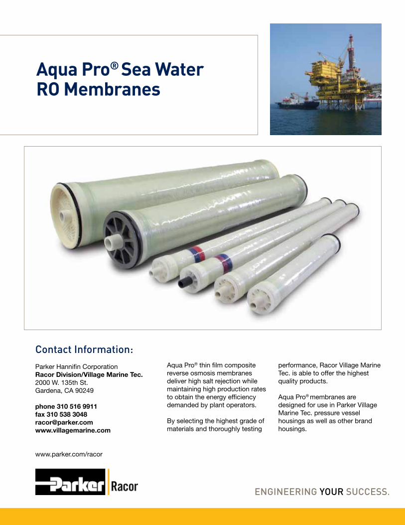
Aqua Pro® Sea WaterRO Membranes
Contact Information:Parker Hannifin CorporationRacor Division/Village Marine Tec.2000 W. 135th St.Gardena, CA 90249
phone 310 516 9911fax 310 538 [email protected]
www.parker.com/racor
Aqua Pro® thin film composite reverse osmosis membranes deliver high salt rejection while maintaining high production rates to obtain the energy efficiency demanded by plant operators.
By selecting the highest grade of materials and thoroughly testing
performance, Racor Village Marine Tec. is able to offer the highest quality products.
Aqua Pro® membranes are designed for use in Parker Village Marine Tec. pressure vessel housings as well as other brand housings.

• MaximumOperatingPressure:1000 psi
• MaximumOperatingTemperature:113°F (45°C)
• MaximumFeedTurbidity:1 NTU• FreeChlorineTolerance:0 PPM
• MaximumFeedSiltDensityIndex:SDI 5
• pHRange: Continuous Operation:4-11 Short-term for Cleaning:(30minuteduration)2.5-11
Aqua Pro®
Sea Water RO Membranes
Notes:
RecommendedOperating Limits:
A
BTYP
CD15°
Nominal Size
2519251925192538253840406040
Product FlowGPD m3/day
220 - 0.83150 - 0.57105 - 0.40550 - 2.08210 - 0.80
1200 - 4.542500 - 9.47
Typical SaltRejection %
99.499.299.299.499.299.499.4
VMTPart No.
33-251933-3000 **33-3001**33-0238
33-3002**33-044033-0036
Dimensionsinches/cm
A*19/4819/4819/48
38/96.538/96.540/101.640/101.6
B1.1/2.81.1/2.81.1/2.81.1/2.81.1/2.81.0/2.51.27/3.2
C0.75/1.90.75/1.90.75/1.9 0.75/1.90.75/1.90.75/1.91.5/3.8
D2.4/6.12.4/6.12.4/6.12.4/6.12.4/6.1
3.96/10.15.98/15.2
• Keepelementsmoistatalltimes
• Permeateobtainedfromfirsttwohoursofoperationshouldbediscarded
• Topreventbiologicalgrowthduringstorage,shipping,orsystemshutdownsitisrecommendedthatelementsbeimmersedinaprotectivesolution.Thestandardsolutionforlongorshorttermstorageshouldcontain1.0percent(byweight)sodiummetabisulfite(availableasVMTp/n85-0103,85-0038,85-0044or85-0049)
• Standarizedtestconditionsare32,000ppmNaClat77°F(25°C),with800psifeed.Productionratesforindividualelementsmayvary+/-20%andrejectionmayvary+/-0.4%
*All19”and38”elementscomewitha2”removableextendersothatthestockedsizealsofits21”and40”housings**Elementsarespeciallydesignedforlowfeedflowapplications.UseonlywithcertainSeaQuencherandLittleWonderwatermakers.
Print Reorder Number 7897 Rev- 11-25-2009© 2009 Parker Hannifin Corporation
To maintain peak performance always use genuine Parker-Racor/Village Marine Tec. replacement parts.We reserve the right to change our specifications or standards without notice.

The Village Marine Tec. line of pleated filters are designed specifically for the RO watermaker industry and are superior to wound or polyspun cartridges to give you a longer filter life as well as increasing flow rates and keeping cartridge size down.
Available in a wide arrange of sizes and micron ranges to ensure that every type of watermaker filter need is taken care of. Stock sizes fit most standard filter housings, if the size you need is not shown please contact us with the dimensions required.
Pleated Filters and Filter Cartridge Kits
Contact Information:Parker Hannifin CorporationRacor Division/Village Marine Tec.2000 W. 135th St.Gardena, CA 90249
phone: 310 516-9911 800 C-Parkerfax: 310 538-3048email: [email protected]
www.parker.com/racor
Single use Cleaning and Preservative Cartridge Kits are designed specifically for small RO Systems. The Cartridges allow for easy and effective membrane maintenance.
The Cleaning and Preservative Cartridge Kits eliminate the trouble and mess of measuring powdered chemicals and ensuring correct chemical concentrations. The Chemical cartridges fit directly into 2.5” x 10” or 4.5” x 10” housings and contain the correct amount of chemical for a single use.

Pleated Filters• Polypropylene pleated
construction• Longer service life over wound
or polyspun cartridges• Easily cleaned and reused• Chemically compatible with
a wide range of alkalies, most acids and saline solutions
• 0.5, 1, 5, and 20 micron nominal ratings available
• Pliable ends ensures filter seal to eliminate bypass
• High packing density reduces filter size while keeping flow rates up
Filter Cartridge Kits• Cartridge with Blue stripe
contains cleaner #1, a biological cleaner to remove algae, fungi and bacteria
• Cartridge with Red stripe contains cleaner #2, an acidic cleaner to remove scale from the membrane
• Cartridge with Green stripe contains the preservative. This chemical is used for pickling the membranes
• Cartridges are capable of being used in any housing that takes a standard 2.5” (64mm) x 10” (254mm) filter cartridges
Pleated Filters and Filter Cartridge Kits
Features:
Carbon Flushing Filters
Cartridge Filter Kits
Pleated Sediment Elements
Part Number
33-011833-011733-005333-005233-002033-000533-005833-005733-017233-210033-510033-110033-1105
Microns
205
205
205
205
1002051
0.5
Filter Areaft3/m3
30/2.7930/2.79
100/9.29 100/9.29100/9.29100/9.29100/9.29
Diameterinch/cm2.75/72.75/7
4.5/11.44.5/11.48.63/228.63/224.5/11.44.5/11.48.63/22 8.63/228.63/228.63/228.63/22
Lengthinch/cm9.75/259.75/259.75/259.75/257.75/207.75/2020/5120/51
24.3/62 24.3/6224.3/6224.3/6224.3/62
Diameterinch/cm2.75/7
4.5/11.44.5/11.4
Lengthinch/cm9.75/259.75/2520/50.8
Part Number
33-031133-031533-0083
Part Number
85-0102
85-0103
Description
Cleaning Kit
Preservation Kit
Contents
One Blue stripe cleaner #1 plusOne Red stripe cleaner #2
Two Green stripe preservative
Print Reorder Number 7905 Rev- 11-23-2009© 2009 Parker Hannifin Corporation
To maintain peak performance always use genuine Parker-Racor/Village Marine Tec. replacement parts.We reserve the right to change our specifications or standards without notice.
Related Documents


![THE QUBE - Paper Mountain · THE QUBE COVER: Untitled (CUBE TWO), 2015 wood, iron 1800 x 1800 x 1800 mm ABOVE, RIGHT: Untitled (CUBE TWO) [detail], 2015 wood, iron 1800 x 1800 x 1800](https://static.cupdf.com/doc/110x72/5fcb894cc8c4976b0c183fa4/the-qube-paper-mountain-the-qube-cover-untitled-cube-two-2015-wood-iron-1800.jpg)