LRIT TRANSMITTER SPECIFICATION 1.0 Introduction The National Oceanic and Atmospheric Administration (NOAA) Low Rate Information System (LRIT broadcast system is an imagery and environmental products delivery system based on the Coordination Group for Meteorological Satellites Global Specification for High Rate and Low Rate Information Transmission (HRIT/LRIT). The global specification is based on the OSI Standard 7498 and the CCSDS recommendations of Advanced Orbiting Systems (AOS). It defines the structure and formatting of the LRIT files and the processing and transport protocols of all OSI layers applicable to all geostationary meteorological spacecraft. The LRIT/HRIT Global Specification can be located at http://www.wmo.ch/pages/prog/sat/documents/CGMS-03_HRIT-LRIT_v2- 6.pdf . 1.1 LRIT Service The functions performed by the LRIT processor are arranged according to the standards of the CCSDS. The NOAA mission is named LRIT because the communications link provides for a relatively low data rate below 256 kbps. The LRIT broadcast from the Geostationary Operational Environmental Satellites (GOES) I-M and N-P Series of satellites has a data rate of 128 kilobits per second. 1.2 Document Structure The flow of this document will follow the chronological flow of events in the processing of each data file for transmission. Primarily, the sections will correspond to the layers in the OSI reference model. 2.0 Introduction to the GOES-Specific OSI Reference Model This section discusses the logical categorization of functions, OSI reference model, GOES-specific implementation, outside data sources, dissemination, partitioning of data files in the application layer, compressing files in the application layer, as well as encryption in the application layer.

Welcome message from author
This document is posted to help you gain knowledge. Please leave a comment to let me know what you think about it! Share it to your friends and learn new things together.
Transcript
LRIT TRANSMITTER SPECIFICATION
1.0 Introduction
The National Oceanic and Atmospheric Administration (NOAA) Low Rate Information System (LRIT broadcast system is an imagery and environmental products delivery system based on the Coordination Group for Meteorological Satellites Global Specification for High Rate and Low Rate Information Transmission (HRIT/LRIT). The global specification is based on the OSI Standard 7498 and the CCSDS recommendations of Advanced Orbiting Systems (AOS). It defines the structure and formatting of the LRIT files and the processing and transport protocols of all OSI layers applicable to all geostationary meteorological spacecraft. The LRIT/HRIT Global Specification can be located at http://www.wmo.ch/pages/prog/sat/documents/CGMS-03_HRIT-LRIT_v2-6.pdf.
1.1 LRIT Service
The functions performed by the LRIT processor are arranged according to the standards of the CCSDS. The NOAA mission is named LRIT because the communications link provides for a relatively low data rate below 256 kbps. The LRIT broadcast from the Geostationary Operational Environmental Satellites (GOES) I-M and N-P Series of satellites has a data rate of 128 kilobits per second.
1.2 Document Structure
The flow of this document will follow the chronological flow of events in the processing of each data file for transmission. Primarily, the sections will correspond to the layers in the OSI reference model.
2.0 Introduction to the GOES-Specific OSI Reference Model
This section discusses the logical categorization of functions, OSI reference model, GOES-specific implementation, outside data sources, dissemination, partitioning of data files in the application layer, compressing files in the application layer, as well as encryption in the application layer.
2.1 Logical Categorization of Functions
The communications service can be logically considered in three functions:
1. Packetizing of the data files for transmission over the communications channel.
2. Data file encoding for transmission efficiency and data protection. These functions are the compression and encryption of the files. Both functions are optional. The GOES mission-specific implementation does not use encryption but provides a means for implementation if requirements change. Compression is performed within the LRIT communications processor.

3. Communications encoding for error control. These processes include block error check coding, bit interleaving, bit randomizing, and convolutional coding. These are optional functions in the CCSDS model. The LRIT processor at the Wallops Command and Control Acquisition (WCDA) Station performs these functions.
2.2 OSI Reference Model
The OSI seven-layer reference model is shown below in Table 1.
OSI Layer Layer FunctionalityApplication Layer - Acquisition of application dataPresentation Layer - Image segmentation
- Formatting to LRIT file structureSession Layer - Compression (optional)
- Encryption (if required)Transport Layer - Determination of APID
- Split of files into source packetsNetwork Layer - Determination of VCIDData Link Layer - Assembly of source packets into M_PDUs
- Multiplexing - Assembly of VCDUs - Generation of 'idle frame' - Reed-Solomon coding - Randomization - Attachment of synchronization marker
Physical Layer - Serialization- Convolutional coding- Modulation
Application Layer - Acquisition of application dataPresentation Layer - Image segmentation
- Formatting to LRIT file structureSession Layer - Compression (optional)
- Encryption (if required)
Table 1 Layer Functionality (Usual Order of Implementation)
2.3 GOES-Specific Implementation
The NOAA GOES system architecture divides the processing layers into five domains and two locations.
2.3.1 Physical Location of Functional Units
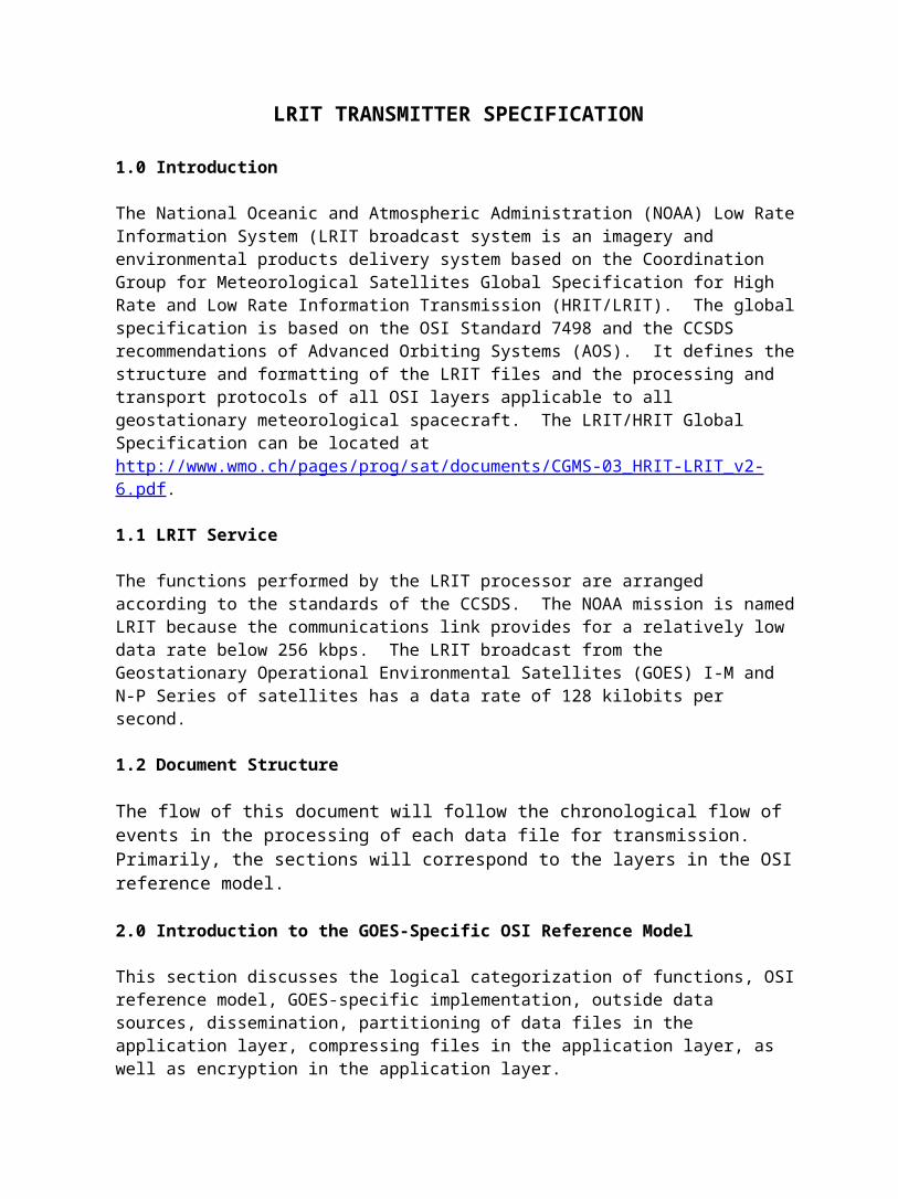
LRIT Domains 1-4 are located at the NOAA Satellite Operations Facility (NSOF) in Suitland Maryland and Domain 5 is located at the Wallops Command and Data Acquisition Station (WCDA) at Wallops Virginia. Between these facilities, the data are transmitted on a multiplexed T1 data line.

2.3.2 LRIT Domain Processors
The processing of the LRIT files for transmission occurs in five separate domains as illustrated in Figure 1.
Figure 1 LRIT System Overview
The GOES mission-specific implementation may have the functions performed as indicated in Table2.
OSI Layer Layer FunctionalityEncoding For Data Transmission Efficiency - Domains 1 and 2Application Layer - Acquisition of application data
- Image partitioning (according to image features)- Encryption (Optional)
Packetizing For Transmission – Domains 3 and 4Presentation Layer
- Formatting to LRIT file structure
Session Layer - Encryption (optional)Transport Layer - Determination of APID
- Split of files in source packetsNetwork Layer - Determination of VCIDData Link Layer - Assembly of source packets into M_PDUs
- Multiplexing- Assembly of VCDUs- Attachment of synchronization marker
Error Control Functions – Domain 5Physical Layer - Insert VCDUs from other sources
- Generation of 'idle frame'
- Interleaving- Reed-Solomon coding- Randomization- Serialization- Convolutional coding- -Modulation (NRZ-L, BPSK)
Table 2. Layer Functionality (GOES-Specific Implementation)
2.4 Data Sources
The primary data source for the NOAA LRIT broadcasts is reduced resolution GOES imagery received on a satellite dish at the NSOF and ingested by the Advance Front End Processor (LRIT Domain 1) or AFEP. Other data sources include:A few options are being considered for assimilation of outside data into the LRIT bit stream. • GOES Data Collection Service (GOES DCS) files received at the WCDA are
transmitted over INTERNET to LRIT Domains 2/3. • Emergency Managers Weather Information Network (EMWIN) data
stream received from the National Weather Service in Silver Spring, Maryland and inserted into the LRIT stream in LRIT Domain 4.
• Graphics files of Japanese Meterological Agency (JMA) MTSAT and The European Organisation for the Exploitation of Meteorological Satellites Meteosat EUMETSAT imagery. The data received at the NSOF from NOAA web sites are inserted into the data stream at domain 2/3, the LRIT products processor.
• Tropical weather products in graphics and text formats pulled from NOAA world wide web sites and inserted into LRIT Domain 2/3.
• Administrative text messages inserted directly into the system by NOAA personnel.
The application files from sources other than the AFEP are inserted into the CVCDU data stream according to a predetermined priority scheme.
2.5 Dissemination
The image and product dissemination is no longer governed by fixed time slots. The start and end time of dissemination for a LRIT file is not bound to absolute time references. The dissemination service maintains in principle a regular, periodic distribution of the image data based on the GOES East and West schedules. These schedules can be found at the NOAA Office of Satellite Operations web site at http://www.oso.noaa.gov/goes/schd-sector/index.htm. Meteorological data and service messages are interleaved with the image data according to a priority scheme. International satellite data, Meteosat and MTSAT imagery from EUMETSAT and JMA and data from the U.S. National Weather Service are interleaved with the data generated by NOAA.
2.6 Partitioning of Data Files in the Application Layer

According to the OSI standard, images that are contained in large files may be segmented in the presentation layer. Segmentation in the presentation layer is based upon a transmission block size. Image partitioning by the application layer processor can be based upon some characteristic of the data itself (i.e., scan lines). Each image partition becomes a separate file. This design allows the user's application processor to partially recover from lost data packets. In order to implement image partitioning, the sequencing of the segments must be indicated within the data field of the files. The user application processor reassembles the image file.
2.7 Compressing Files in the Application Layer
Similarly to segmentation, the files can be compressed in the application layer to reduce the need for compression in the session layer. Compression algorithms in the application layer might take advantage of the knowledge of the image characteristics. If compression occurs in the application layer at the transmit end it must also be expanded in the user's application processor.
2.8 Encryption in the Application Layer
Data encryption is not part of the requirements for the GOES LRIT architecture; however, the architecture should include a means to add encryption if requirements change. Adding this capability at the application layer would require the user application processor to have the capability to decrypt the message. LRIT files will also carry a field designating the intended recipient.
3.0 Application Layer
The application layer provides specific services between application processes.
3.1 GVAR Format Data
GVAR data are converted to LRIT products in Domain 1 and Domain 2/3 as shown in Figure 1. The observation data from the satellite are transmitted in a raw form to the facility at Wallops Island, Virginia. There they are formatted and retransmitted back to the satellite for distribution as GVAR format data products.
3.1.1 Central Environmental Satellite Computer System
Advanced Front End Processor (AFEP)
The AFEP receives the GVAR data and other data from the GOES satellites through antennas at the NSOF. Along with other product formats, the AFEP creates the Level 1A meteorological products for distribution to the LRIT system. The AFEP builds partial image files from a fixed number of scan lines. This subdivision of the full image reduces the size of transmitted files, reduces latency, and provides a means for the user terminal to build an image even though some data are corrupted through the transmission system. Along with

each file, this processor creates a metadata file with all the data needed by the LRIT products processor (Domain 2/3) to build LRIT file headers and control the optional actions of the processor (i.e.; implementing priority, encrypting, compressing).
3.1.2 LRIT Products Processor – Domain 2/3
The LRIT product processor receives input from several sources as detailed in paragraph 2.4 – Data Sources. Primarily, Domain 2/3 receives GOES imagery inputs from AFEP –Domain 1 as shown in Figure 1. The naming convention for the file and its metadata file must be such that they can be easily associated. This processor must have knowledge of the parameters of the input data. Fields such as file size, priority, file type, etc. must be stored by the products processor. Domain 2/3 creates LRIT formatted files and sends them to the appropriate LRIT Domain 4 servers (LRIT East and / or West). Details are presented in Section 4 on the presentation layer.
3.1.3 Manual Message Input Device
The LRIT products processor provides a capability to create administrative and informational messages using pre-defined templates on the LRIT Domain 2/3 servers. These messages are used to convey information on outages, status of spacecraft and other subjects related to the LRIT broadcast service.
3.2 GOES File Types
The GOES disseminates: - Image data files in LRIT format
- Visible- Infrared - Water vapor
- EUMETSAT Meteosat and JMA MTSAT images in graphic formats (i.e. GIF)- GOES DCS files in text format- EMWIN data files in text and graphic formats (i.e. GIF) and compressed (.zip)
file- Environmental data files in text and graphic formats (i.e. GIF)
Alphanumeric files - Administrative files in text format
The associated metadata files contain a delimited set of alphanumeric characters that are used to develop the LRIT file headers and pass other necessary information between the LRIT products processor and other processors. Fields in the metadata file closely resemble the fields to be inserted in the LRIT headers. The ASCII 'space' ('20'h) is not used as a delimiter.
3.3 Metadata File Structure
Header_type, 0 Header_record_length, 16 Data_field_length, 32714 File_type_code, 25 Total_header_length, 32758 Header_type, 1 Header_record_length, 9 Number_of_columns,1200 Bits_per_pixel, 64 Number of lines, 1400 Compression_flag, 1 .. Header_type,4 Header_record_length,16

Figure 2 Partial Sample Metadata File Fields
Figure 3 Partial Sample Metadata Delimited File Structure
3.4 Interface between the LRIT Products Processor and LRIT Preprocessor
The interface consists of a communications link, which provides access for the LRIT preprocessor to the data files for transmission. The communications network is connected to the LRIT products processor where GOES LRIT data products are assembled.
4 Presentation Layer Processing at this layer is performed in the LRIT preprocessor, Domain 2/3. The presentation layer defines the uniform formatting of the data and image files. This layer is the beginning of the process of packetizing or data transmission. The transfer mechanism of the GOES dissemination service is based on the transfer of data units that are called LRIT files. These files are the output of the presentation layer and their structure is explained in the following subsections.
4.1 LRIT Preprocessor
The LRIT Products Processor makes available to the LRIT preprocessor the data files for transmission and the corresponding metadata files with information on the content of the data files. This layer receives the data streams from the application processors by means of having them stored on a media accessible to both the LRIT processor and the application processors. Application files and the corresponding metadata files are processed in the order in which they are received. The header fields are built using the information contained in the
;0,16,25,32758,32741;1,9,64,1200,1400,1;…;4,16,DATAFILENAME.txt

metafiles. Once the files have been converted to LRIT files, the original files are purged from the storage media.
4.2 Structure of LRIT Files
Each application data unit to be distributed is formatted to an LRIT file. An LRIT file consists of one or more header records and one data field. The information for creating the header files will be contained in the metadata file.
The primary header record is mandatory and defines the file type and the sizing of the complete LRIT file. Depending on the file type, one or more secondary headers may be required to provide ancillary file information.
The header contains important data relating to the further processing of the LRIT files. Priority for transmission is established by transferring the priority indicator in the metadata file (or optionally having the processor know the correlation between the data file and the priority) to a priority parameter called "PRIO" in the LRIT file header. Fields in the header will trigger encryption and compression processes, which are created by corresponding fields in the metadata file. Some header fields will be inserted into the LRIT file during later processing.
PrimaryHeader
#0
Secondary HeaderRecords(#1 -
#127)
Secondary HeaderRecords(#128 - #255)
Data Field
Figure 4 LRIT File Structure

4.3 Segmentation of LRIT Files
LRIT files segmented in this layer will be called image segment files.
Details of segmentation are presented in Section 4 of LRIT/HRIT Global Specification, CGMS 03, and dated August 12, 1999.
4.4 Overview of LRIT File Types
Table 3 presents an overview of LRIT file types.
File Type Code File Type Application Data Type Contained in the Data Field
Global LRIT File Type0 Image data1 Messages2 Alpha-numeric text3 Encryption key message Optional4 Reserved Mission-Specific LRIT File Type128 Meteorological data129…255 Reserved
Table 3 LRIT File Types
4.4.1 General
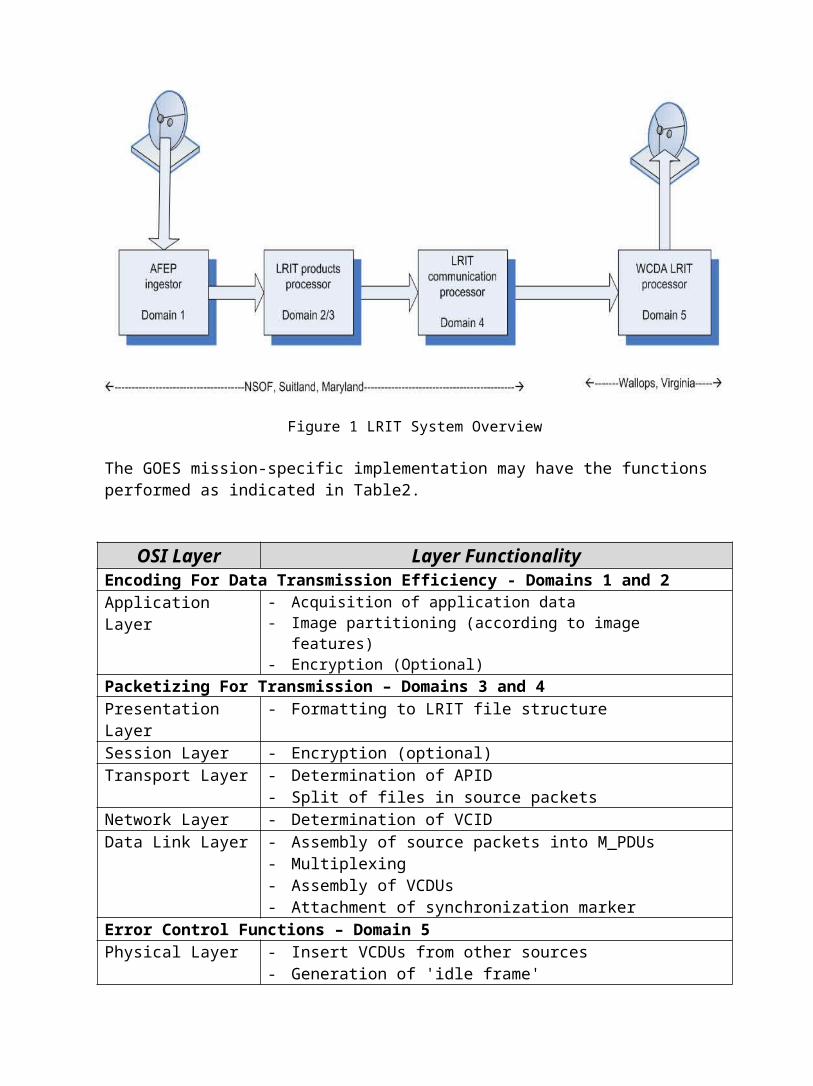
Table 4 shows the adaptation of LRIT header types.
Code Header Record Type Structure Headers as Defined in LRIT Global Specification0 Primary header 1 Image structure 2 Image navigation 3 Image data function 4 Annotation 5 Time stamp 6 Ancillary text 7 Key header Optional 8…127 Reserved Mission-Specific Headers128 Segment identification 129 Encryption key message 130…255 Reserved
Table 4 Adaptation of LRIT Header Types

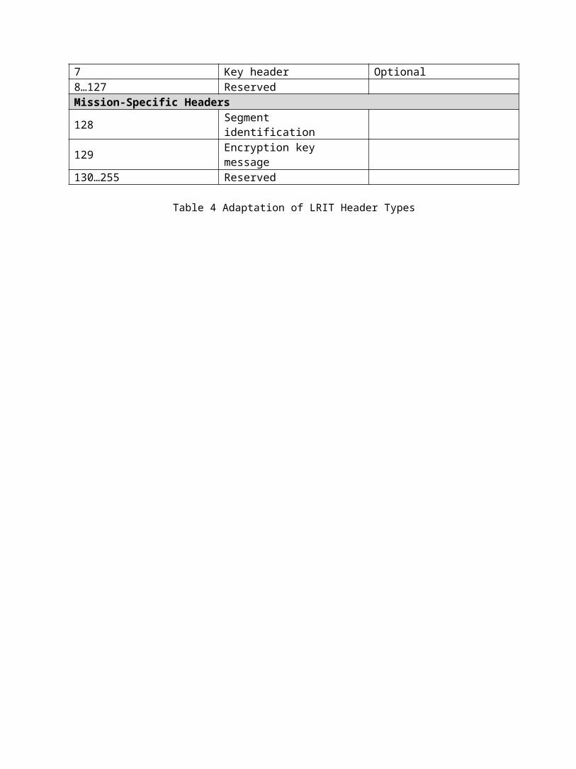
4.4.2 Primary Header Format The primary header is required for all LRIT files. The structure of the primary header record is as follows:
Size in Octets Data Type Contents 1 Integer, unsigned Header type, set to 0 2 Integer, unsigned Header record length, set
to 16
1 Integer, unsigned File type code, determining the top level structure of the file data field
4 Integer, unsigned Total header length, specifying the total size of al header records
8 Integer, unsigned Data field length, specifying the total size of the file data field in bits.
Table 5 LRIT Primary Header Format
4.4.3 Secondary Header Formats
Seven additional secondary headers can be used as defined in the CGMS Specification, CGMS 03, Issue 2.6, August 12, 1999. Two additional secondary header types are defined for mission specific applications. The secondary header types are shown in Table 4.
4.4.4 Image Structure Record
This record determines the structure of the image. It is mandatory for and only applicable to image data files. The structure is as follows:
Size in Octets Data Type Contents 1 Integer, unsigned Header type, set to1 2 Integer, unsigned Header record length, set
to 9 1 Integer, unsigned Number of bits per pixel
(1…255) 2 Integer, unsigned Number of columns (1…
65535) 2 Integer, unsigned Number for lines (1…
65535) 1 Integer, unsigned Compression flag (0,1,2)
Table 6 Image Structure Record
The image record is three-dimensional. Each picture element (pixel) is in an

array with horizontal and vertical alignment with other elements in the array. For each pixel there are a number of bits that gives the characteristics of that pixel, such as intensity, shading, and hue. The file structures will be as follows:
LRIT ProductNumber of
Bitsper Pixel
Number of
Columns
Number of Lines
GOES
Full Disk 8 1396 698North Hemisphere 8 1396 740South Hemisphere 8 1396 740North West 8 1396 740North East 8 1396 698South West 8 1396 690South East 8 1396 740Environmental productsNWS 8 1200 900
(varies)GMS 8 1200 804METEOSAT 8 1200 804
Table 7 Data Field Parameters for LRIT Image Files
The compression flag determines if compression will be performed. It will not be a function of the LRIT communications processor to determine if compression is needed. The values will be: "0" no compression, "1" lossless compression.
4.4.5 Image Navigation Record
This record determines the mapping of the image onto the Earth. It is only applicable to image data files. The structure is as follows:
Size in Octets Data Type Contents Abbreviation 1 Integer, unsigned Header type, set
to2
2 Integer, unsigned Header record length, set
32 Character Projection name 4 Integer, unsigned Column scaling
factor CFAC 4 Integer, unsigned Line scaling factor LFAC 4 Integer, unsigned Column offset COFF 4 Integer, unsigned Line offset LOFF
Table 8 Image Navigation Record The LRIT dissemination may use projection names such as Geostationary, Polar-
stereographic, and Mercator. All unused characters will be set to an ASCII 'space' ('20'h).
- CFAC/LFAC - The column and line scaling factors contain variable values that depend on the input data and their specific segmentation approach. The sign of the CFAC/LFAC values will define the spacecraft's scan direction.
- COFF/LOFF - These values are projection-specific offsets and define the position of an image segment file window within the projection area.
4.4.6 Image Data Function Record This record determines the physical meaning of the image data. The structure is as follows:
Size in Octets Data Type Contents 1 Integer, unsigned Header type, set to 3 2 Integer, unsigned Header record length Up to 65532 Character Data definition block
Table 9 Image Data Function Record
Data Definition Block
This character string allows the definition of complex data structures. It can be used to define overlay-type images and images that require the establishment of a relationship between their pixel values and an engineering unit. This header type will only be included in the files containing imagery type or overlay type of meteorological products, foreign satellite data, or service messages.
4.4.7 Annotation Record
This header is used to specify an alphanumeric annotation for the file. Header type 4 is mandatory and contains in characters the name of the file as presented by the LRIT Products Processor. The structure is as follows:
Size in Octets Data Type Contents 1 Integer, unsigned Header type, set to 4 2 Integer, unsigned Header record length Up to 64 Character Annotation text
Table 10 Annotation Record
The annotation text is used to transfer the file names for the products. The extra capacity of the character field can be available for other data or annotations as needed. As an alternative architecture, another header type can be assigned to the file name.
4.4.8 Time Stamp Record
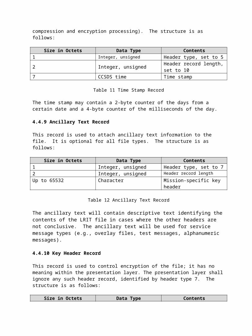
This record is used to apply a time stamp to the file; it is optional for all file types. The LRIT mission represents the time that the image was processed for transmission. The insertion of this header does not occur in this layer. The time stamp is written after the end of the session layer processing (i.e., after compression and encryption processing). The structure is as follows:
Size in Octets Data Type Contents 1 Integer, unsigned Header type, set to 5 2 Integer, unsigned Header record length, set
to 10 7 CCSDS time Time stamp
Table 11 Time Stamp Record
The time stamp may contain a 2-byte counter of the days from a certain date and a 4-byte counter of the milliseconds of the day.
4.4.9 Ancillary Text Record
This record is used to attach ancillary text information to the file. It is optional for all file types. The structure is as follows:
Size in Octets Data Type Contents 1 Integer, unsigned Header type, set to 7 2 Integer, unsigned Header record length Up to 65532 Character Mission-specific key
header
Table 12 Ancillary Text Record
The ancillary text will contain descriptive text identifying the contents of the LRIT file in cases where the other headers are not conclusive. The ancillary text will be used for service message types (e.g., overlay files, test messages, alphanumeric messages).
4.4.10 Key Header Record
This record is used to control encryption of the file; it has no meaning within the presentation layer. The presentation layer shall ignore any such header record, identified by header type 7. The structure is as follows:
Size in Octets Data Type Contents 1 Integer, unsigned Header type, set to 7 2 Integer, unsigned Header record length Up to 65532 Character Mission-specific key
header

Table 13 Ancillary Text Record
This header record will not be used unless LRIT GOES mission requirements change; however, the capability to provide this header will be provided. The specifics will depend upon the encryption scheme chosen.
4.4.11 Segment Identification Record
This record is used for images such as a full Earth disk image. This image will be sent in files that contain partitions of the image. A partition refers to the image portions created in the application layer. For example, if the image contains 2048 lines and each file contains 16 lines of the image, 128 individual files will be sent and the segment identification record will provide the sequence number.
Size in Octets Data Type Contents1 Integer, unsigned Header type, set to 128 2 Integer, unsigned Header record length, 8 1 Integer, unsigned Segment sequence
number 1 Integer, unsigned Total number of
segments in image 2 Integer, unsigned TBD - options available 1 Integer, unsigned Image type 1 Integer, unsigned Header type, set to 128
Table 14 Segment Identification Record
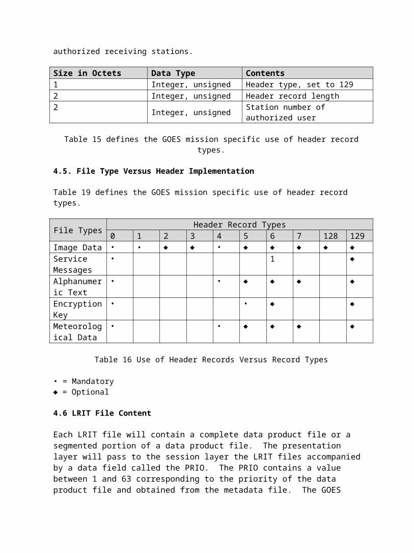
4.4.12 Encryption Key Message Header Record
If encryption is used, this header will be used to identify the authorized receiving stations.
Size in Octets Data Type Contents1 Integer, unsigned Header type, set to 1292 Integer, unsigned Header record length2 Integer, unsigned Station number of authorized
user
Table 15 defines the GOES mission specific use of header record types.
4.5. File Type Versus Header Implementation
Table 19 defines the GOES mission specific use of header record types.
File Types Header Record Types0 1 2 3 4 5 6 7 128 129
Image Data • • ♦ ♦ • ♦ ♦ ♦ ♦ ♦Service • 1 ♦

MessagesAlphanumeric Text
• • ♦ ♦ ♦ ♦
Encryption Key
• • ♦ ♦
Meteorological Data
• • ♦ ♦ ♦ ♦
Table 16 Use of Header Records Versus Record Types
• = Mandatory ♦ = Optional
4.6 LRIT File Content
Each LRIT file will contain a complete data product file or a segmented portion of a data product file. The presentation layer will pass to the session layer the LRIT files accompanied by a data field called the PRIO. The PRIO contains a value between 1 and 63 corresponding to the priority of the data product file and obtained from the metadata file. The GOES implementation will use the priority range from 1 to 6.
5.0 Session Layer – Domain 4
This section gives a general overview and discusses input to the session layer, compression, encryption, as well as session layer output.
5.1 General
The session layer provides the means for interchange of data. In the GOES context, this layer includes the definition of data compression and encryption. It is the first layer in domain 4.
All data that are not subject to compression or encryption will pass the relevant data processing functionality unmodified and will receive its primary header record completed with the known data field length and time stamp.
In the case the data field of the LRIT files is compressed and/or encrypted, the session layer functionally will modify or insert the following headers/header fields after processing:
For Compression: Header type #0, Data_Field_Length Header type #1, Compression_Flag For Encryption: Header type #7, Header Information
5.2 Input to Session Layer

The LRIT files as shown in Figure 4 are the input to the session layer processing.
5.3 Compression
Compression is required to maximize the data availability of the LRIT channel. An appropriate data compression technique is to be determined for the GOES-specific implementation.
Figure 5 LRIT File Structure with Compressed Data Field
Lossless data compression is preferred for the GOES. Compression standards are presented in OSI Standard 10918. The compression technique for the GOES implementation is to be determined.
5.4 Encryption The GOES LRIT service does not presently require a mechanism to control the access to LRIT. If capabilities for data control are anticipated, the means for encryption and the necessary fields on the file structures must be provided. Also, encryption may be applied to the data files in the application layer.
5.5 Session Layer Output
Output of the session layer to the transport layer is the Session Protocol Data Unit (S_PDU) containing the variable length compression and encrypted data field as shown in Figure 6. The PRIO parameter indicting transmission priority is also passed with each S_PDU to the transport layer.
Figure 6 LRIT Session Protocol Data Unit (S_PDU)
If neither compression nor encryption has been applied, the session layer will leave the data field unmodified.
The session layer processing will have to determine the data field length, fill it into the primary header, and add the time stamp (if required) before it passes the complete data unit as S_PDU to the transport layer. If the time stamp is used, the time will be determined from the system real time clock, formatted as required by the mission, and a time-stamp header type #5 inserted into the LRIT file.
6.0 Transport Layer

This section gives a general overview of the transport layer and discusses source packetization.
6.1 General
Functions of the transport layer are implemented in domain 4. The transport layer receives the session layer service data units (S_PDUs) as a transport service data unit (TP_SDU), which is a variable length file.
The determination of the application process identifier (APID) will be performed in order to implement the transmission priority. GOES LRIT implements a six-level priority scheme.
The transport files are split into one or more blocks of 8190 bytes size, which form the user data field of the source packet. The last block may be shorter and contain 1…8190 bytes. Each user data field will be followed by a 2-octet Cyclic Redundancy Check (CRC).
6.2 Source Packetization
This section discusses source packet structure and APID determination. 6.2.1 Source Packet Structure This section defines in detail the source packet structure:
Source Packet Header Packet Data Field (variable)
Packet Identification Packet Sequence Control
Packet
Length
16 bits
User Data FieldVersion No.
3 bits
Type
1 bit
Secondary
Header Flag
1 bit
APID
11 bits
Sequence
Flags
2 bits
Packet Sequen
ce Count
14 bits
Application Data
Field
Variable
Packet Error
Control (CRC)
16 bits
2 octets 2 octets 2 octets
Max. 8190 octets
2 octets
Figure 7 Source Packet Structure (TP_PDU)
Version Number - The version number bits will be set to 000, identifying the Version-1 CCSDS packet.
Type - Set to '0'b. Type is not used in CCSDS AOS.
Secondary header flag - Set to '0'b. A secondary header is not used in the LRIT dissemination Service
APID - See Table 16.
Application Process Identifier (APID) Application‘0…191’ GOES LRIT application data‘192…2015’ Not used‘2016…2046’ Reserved by CCSDS (not used for
LRIT)‘2047’ Fill packets
Table 17 Application Process Identifiers
Sequence Flag As defined :
- Set to 3 if the user data contains one user data file entirely;
- Set to 1 if the user data contains the first segment of one user data file extending through subsequent packets;
- Set to 0 if the user data contains a continuation segment of one user data file still extending through subsequent packets;
- Set to 2 if the user data contains the last segment of a user data file beginning in an earlier packet.
Packet Sequence Count- 14-bit packet sequence count, straight sequential count (modulo 16394) that numbers each source packet generated per APID.
Packet Length - 16-bit binary count that expresses the length of the remainder of the source packet following this field minus 1.
Application Data Field - Contains up to 8190 octets of user data (i.e., a block of the TP_SDU).
Packet Error Control - The 16-bit CRC forms the trailer of the user data field.
- The CRC is computed over the entire application data field.
The generator polynomial is: g(x) = x16 + x12 +x5 + 1- The encoder shall be initialized to 'all ones' for each

application data field.6.2.2 APID Determination
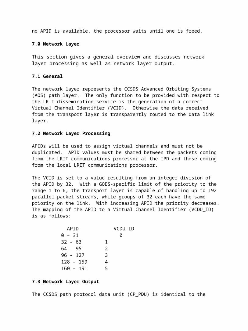
The APID is used to determine the order in which packets are transmitted. It conveys the priority of the packet, which will be used later when assigning a virtual channel. As a possible implementation, the transport layer processor could read the priority code of the LRIT file from the PRIO parameter. Each priority level has 32 APIDs. The next available APID is selected for the priority level and assigned to the LRIT file. If no APID is available, the processor waits until one is freed.
7.0 Network Layer
This section gives a general overview and discusses network layer processing as well as network layer output.
7.1 General
The network layer represents the CCSDS Advanced Orbiting Systems (AOS) path layer. The only function to be provided with respect to the LRIT dissemination service is the generation of a correct Virtual Channel Identifier (VCID). Otherwise the data received from the transport layer is transparently routed to the data link layer. 7.2 Network Layer Processing APIDs will be used to assign virtual channels and must not be duplicated. APID values must be shared between the packets coming from the LRIT communications processor at the IPD and those coming from the local LRIT communications processor.
The VCID is set to a value resulting from an integer division of the APID by 32. With a GOES-specific limit of the priority to the range 1 to 6, the transport layer is capable of handling up to 192 parallel packet streams, while groups of 32 each have the same priority on the link. With increasing APID the priority decreases. The mapping of the APID to a Virtual Channel Identifier (VCDU_ID) is as follows:
APID VCDU_ID0 – 31 032 – 63 164 – 95 296 – 127 3128 – 159 4160 – 191 5
7.3 Network Layer Output
The CCSDS path protocol data unit (CP_PDU) is identical to the initial CP_SDU;

however, it is forwarded through the network layer. The output includes packets from all sources and their corresponding virtual channel number.
8.0 Data Link Layer
This section discusses the input to the data link layer, general overview, VCLC sub layer processing, VCA sub layer processing, as well as transfer to domain 5.
8.1 Input to Data Link Layer
The network layer provides the CP_PDUs as multiplexing service data units (M_SDU) to the data link layer.
8.2 General
The data link layer encompasses functionality of the CCSDS space line layer with its two sub layers:
• Virtual channel link control (VCLC) sub layer • Virtual channel access (VCA) sub layer
As described in Section B.8.3, the VCLC sub layer processing provides the multiplexing service only. This includes filling of M_SDUs into multiplexing protocol data units (M_PDU). Fill packets may have to be generated for the completion of the M_PDUs after time-out expiration.
The VCA sub layer generates the virtual channel data units (VCDU), performs Reed-Solomon coding, data randomization, and attachment of synchronization markers.
As an optional GOES-specific architecture the VCA sub layer forms the VCDUs into a continuous data stream with synchronization markers and delivers it to the physical layer without Reed-Solomon coding or data randomization.
8.3 VCLC Sub layer Processing
The VCLC sub layer processing performs the multiplexing, the M_PDU generation and the related fill packet generation.
The M_PDUs will consist of 886 octets of which 2 octets are the M_PDU header and the 844 octets are the M_PDU packet zone as follows:
M_PDU Header M_PDU Packet ZoneSpare
5 bits
First Header Pointer11 bits
End of M_SDU# (k-1)
M_SDU
# k
M_SDU
# (k+1)
. . .
Beginning of M_SDU
# m
2 octets 884 octets

Figure 8 M_PDU Structure.
8.3.1 Fill Packet Generation
In case that the partly generated M_PDU cannot be completed, since no more M_SDU is available for the related virtual channel, a fill packet is generated to complete the M_PDU.
8.4 VCA Sub layer Processing
This section discusses VCDU assembly, sync marker attachment, as well as serialization and output of the data link layer.
8.4.1 VCDU Assembly The M_PDUs from the VCLC layer are received as VCA_SDUs from the VCLC sublayer and are used to assemble VCDUs.
The VCDU structure is shown in Figure 9.
VCDU Primary Header
VCDU Data Unit Zone
6 Octets 886 Octets
Figure 9 VCDU Structure
The decomposition of the VCDU header is given in Figure 10.
Version Number
2 bits
VCDU-ID VCDU Counter24 bits
Signaling FieldS/C ID
8 bits
VC ID6
bits
Replay Flag1 bit
Spare7
bits6 octets
Figure 10 VCDU Primary Header
Mission-specific use: Version Number '01'b
VCDU ID Spacecraft (S/C) ID representing on the disseminating spacecraft. (In the GOES-specific implementation, a
separate processor will be used for each spacecraft. Therefore this filed should be set to zero.) VC ID '63'd ('all ones')
VCDU Counter Sequential count (modulo 16777216) of VCDUs on each virtual channel.

Signaling Field `all zeros`
In the CGMS standard, the Reed-Solomon coding and randomization occur here. A description of the procedures is presented in the physical layer section. The LRIT mission-specific implementation may move this function to the physical layer to permit available components to be used.
8.4.2 Synchronization Marker Attachment
An attached synchronization marker (ASM) will have to precede the VCDU to allow for frame synchronization. The 32-bit pattern can be represented in hexadecimal notation as: '1ACFFC1D'h.
The ASM together with the VCDU creates the channel access data unit (CADU) of 892 octets length.
8.4.3 Serialization and Output of the Data Link Layer
As a final task, the VCA sub layer performs the serialization of the CADU and provides the serial bit stream to the physical layer.
8.5 Transfer to Domain 5
The VCDUs with markers are transmitted over the T-1 line from domain 4’s at Suitland, Maryland to domain 5’s at Wallops Island, Virginia. At this point it is not necessary to transmit a synchronous data stream.
9.0 Physical layer
The physical layer on the LRIT service performs the Reed-Solomon coding, interleaving, randomization, convolutional coding of the serialized data stream, and its modulation onto the RF uplink signal.
9.1 Insertion of Non-CEMSCS Data Products Data from sources other than the ESPC are received at the CDA (DCS files). The GOES DCS data files are transmitted from the CDA to the NSOF and presented to the LRIT products processor (domain 2/3) for LRIT formatting and returned to the CDA within the CVCDU serial data stream. The environmental products from NOAA web sites (NWS) are collected at the NSOF and presented to the LRIT products processor also for LRIT formatting and sent to the CDA within the CVCDU serial data stream. The EMWIN data are collected at NOAA, Silver Spring. The data files are transmitted from Silver Spring to the NSOF and presented to the LRIT communication processor (domain 4) for LRIT formatting and send to the CDA within the CVCDU serial data stream also.
9.2 Reed-Solomon Coding
The LRIT dissemination service is a Grade-2 service (i.e., forward error

correction only). Therefore, the transmission of user data will be error controlled using Reed-Solomon coding as an outer code.
The Reed-Solomon code used is (255,223) with an interleaving of I = 4.
The VCDUs will be attached by 128 octets of Reed-Solomon check symbols to form a coded VCDU (C_VCDU).
VCDU Prima
ry Head
er
VCDU Data Unit Zone Reed-Solomon
Check Symbols
6 octets
886 octets 128 octets
Figure 11 C_VCDU Structure
9.2.1 ‘Fill VCDU' Generation The LRIT has to maintain a "packetized data rate" when sending the data stream through the randomizer, convolutional coder and to the modulator (128 kbps, 64 kbps, or whatever rate is currently being used).
The physical layer processor in domain 5 automatically generates a 'fill VCDU' in the case no or not sufficient VCDUs (underflow condition) are received from the IPD over the T-1 lines to maintain a continuous data flow at the specified packetized data rate to the physical layer.
The definition of a ‘Fill VCDU’ is:
Version '01'b
VCDU ID Spacecraft (S/C) ID depending on the disseminating Spacecraft (Set to zero)
VC ID '63'd ('all ones')
VCDU Counter 'all zeros'
Signaling Field 'all zeros'
VCDU Data Unit Zone fill pattern ('all zeros')
9.3 Randomization
Randomization is applied to all LRIT CVDUs. It is a process in which a pseudo-random sequence is bitwise exclusive-ORed to all 8160 bits of the CVDU to ensure sufficient data transitions.
The pseudo-random sequence is generated using the following polynomial:
H(x) = x8 + x7 +x3 + 1
This sequence begins at the first bit of the CVCDU and repeats after 255 bits, continuing repeatedly until the end of the CVCDU. The sequence generator is then reinitialized to all-ones for the processing of the next CVCDU.
The first 255 bits of the pseudo-random sequence from the generator are shown below. The left-most bit is the first bit of the sequence to be exclusive-ORed with the first bit of the CVCDU. The second bit of the sequence is exclusive-ORed with the second bit of the CVCDU, and so on.
1111 1111 0100 1000 0000 1110 1100 0000 1001 1010 0000 1101 0111 0000 1011 1100 1000 1110 0010 1100 1001 0011 1010 1101 1010 0111 1011 0111 0100 0110 1100 1110 0101 1010 1001 0111 0111 1101 1100 1100 0011 0010 1010 0010 1011 1111 0011 1110 0000 1010 0001 0000 1111 0001 1000 1000 1001 0100 1100 1101 1110 1010 1011 000 and so on…
9.4 Convolutional Coding
The convolutional coding has the following characteristics:
Nomenclature: Convolutional code with maximum-likelihood (Viterbi)
Code rate: ½ bit per symbol Constraint length: 7 bits Connection vectors: G1 = 1111001; G2=1011011 Phase relationship: G1 is associated with the first symbol Symbol inversion:None
9.5 Modulation
The data stream should be shaped with a raised cosine filter having a roll-off factor of α= 0.5. The transmitter modulation is NRZ-L with BPSK modulation. The initial operational capability will transmit data at a data rate of 64 kbps. The final operational capability will operate at a data rate of 128 kbps. The transmitted symbol rate for the final operational capability will be 292.7 kilosymbols per second.
Related Documents