Welcome message from author
This document is posted to help you gain knowledge. Please leave a comment to let me know what you think about it! Share it to your friends and learn new things together.
Transcript


LRFD Bridge Design
Contents Contents

LRFD Bridge DesignFundamentals and Applications
Tim Huff

First edition published 2022by CRC Press6000 Broken Sound Parkway NW, Suite 300, Boca Raton, FL 33487-2742
and by CRC Press2 Park Square, Milton Park, Abingdon, Oxon, OX14 4RN
© 2022 Tim Huff
CRC Press is an imprint of Taylor & Francis Group, LLC
Reasonable efforts have been made to publish reliable data and information, but the author and publisher cannot assume responsibility for the validity of all materials or the consequences of their use. The authors and publish-ers have attempted to trace the copyright holders of all material reproduced in this publication and apologize to copyright holders if permission to publish in this form has not been obtained. If any copyright material has not been acknowledged please write and let us know so we may rectify in any future reprint.
Except as permitted under U.S. Copyright Law, no part of this book may be reprinted, reproduced, transmit-ted, or utilized in any form by any electronic, mechanical, or other means, now known or hereafter invented, including photocopying, microfilming, and recording, or in any information storage or retrieval system, without written permission from the publishers.
For permission to photocopy or use material electronically from this work, access www .copyright .com or con-tact the Copyright Clearance Center, Inc. (CCC), 222 Rosewood Drive, Danvers, MA 01923, 978-750-8400. For works that are not available on CCC please contact mpkbookspermissions @tandf .co .uk
Trademark notice: Product or corporate names may be trademarks or registered trademarks and are used only for identification and explanation without intent to infringe.
Library of Congress Cataloging‑in‑Publication Data
Names: Huff, Tim, author. Title: LRFD bridge design : fundamentals and applications / Tim Huff, Tennessee Technological University Cookeville, Tennessee. Description: First edition. | Boca Raton : CRC Press, [2022] | Includesbibliographical references and index. Identifiers: LCCN 2021043502 (print) | LCCN 2021043503 (ebook) | ISBN9781032208367 (hardback) | ISBN 9781032208374 (paperback) | ISBN 9781003265467 (ebook) Subjects: LCSH: Bridges--Design and construction--Textbooks. | Load factordesign--Textbooks. Classification: LCC TG300 .H84 2022 (print) | LCC TG300 (ebook) | DDC 624.2/5--dc23 LC record available at https://lccn.loc.gov/2021043502LC ebook record available at https://lccn.loc.gov/2021043503
ISBN: 978-1-032-20836-7 (hbk)ISBN: 978-1-032-20837-4 (pbk)ISBN: 978-1-003-26546-7 (ebk)
DOI: 10.1201/9781003265467
Typeset in Timesby Deanta Global Publishing Services, Chennai, India
Access the Support Material at www.routledge.com/9781032208367

v
ContentsPreface.......................................................................................................................ixAcknowledgements ...................................................................................................xiAuthor biography ................................................................................................... xiii
Chapter 1 Introduction ..........................................................................................1
1.1 The Project Bridge .....................................................................11.2 Preliminary Dimensions ............................................................51.3 Bridge Girder Behavior at Various Stages of Construction ........71.4 Bridge Materials ........................................................................91.5 Software for Bridge Engineering ............................................ 131.6 Section Properties .................................................................... 141.7 Solved Problems ...................................................................... 141.8 Exercises ..................................................................................20
Chapter 2 Loads on Bridges ................................................................................23
2.1 Dead Loads (DC and DW) ......................................................242.2 Live and Impact Loads (LL and IM) ......................................252.3 Braking Forces (BR) ................................................................272.4 Centrifugal Forces (CE) ..........................................................272.5 Wind Loads (WS and WL) ......................................................292.6 Collision Loads (CT and CV)..................................................302.7 Temperature Loads (TU) ......................................................... 322.8 Earthquake Loads (EQ) .......................................................... 332.9 Water Loading (WA) ............................................................... 432.10 Solved Problems ......................................................................462.11 Exercises ..................................................................................60
Chapter 3 Load Combinations and Limit States ................................................. 63
3.1 Solved Problems ......................................................................683.2 Exercises ..................................................................................80
Chapter 4 Deck and Parapet Design ................................................................... 83
4.1 Parapet Design ......................................................................... 834.2 Deck Overhang Design ............................................................854.3 Interior Bay Deck Design ........................................................854.4 Solved Problems ......................................................................884.5 Exercises ................................................................................ 106

vi Contents
Chapter 5 Distribution of Live Load ................................................................. 107
5.1 AASHTO Equations .............................................................. 1085.2 The Lever Rule ...................................................................... 1115.3 Rigid Cross-Section Method ................................................. 1125.4 Solved Problems .................................................................... 1135.5 Exercises ................................................................................124
Chapter 6 Steel Welded Plate I-Girders ............................................................ 125
6.1 Flexural Resistance at the Strength Limit State .................... 1266.1.1 Composite Compact Sections in Positive Flexure ....... 1266.1.2 Non-Compact Composite Sections in
Positive Flexure ........................................................ 1286.1.3 Negative Flexure and Non-composite Sections........ 129
6.2 Shear Resistance .................................................................... 1316.3 Transverse Stiffener Design .................................................. 1326.4 Bearing Stiffener Design ....................................................... 1336.5 Fatigue Design ....................................................................... 1346.6 Field Splice Design ................................................................ 1376.7 Stability Bracing .................................................................... 1426.8 Shear Studs ............................................................................ 1466.9 Plastic Moment Computations ............................................... 1486.10 Solved Problems .................................................................... 1486.11 Exercises ................................................................................ 174
Chapter 7 Precast Prestressed Concrete Girders .............................................. 179
7.1 Stress Analysis ....................................................................... 1797.2 Flexural Resistance................................................................ 1807.3 Shear Resistance .................................................................... 1827.4 Continuity Details ................................................................. 1847.5 Mild Tensile Reinforcement in Girders ................................. 1867.6 Negative Moment Reinforcement for Girders
Made Continuous ................................................................... 1877.7 Transfer and Development Length ........................................ 1907.8 Stress Control Measures ........................................................ 1907.9 Solved Problems .................................................................... 1917.10 Exercises ................................................................................ 210
Chapter 8 Bridge Girder Bearings .................................................................... 215
8.1 Elastomeric Bearings ............................................................. 2158.2 Steel Assembly Bearings .......................................................2208.3 Isolation Bearings .................................................................. 2228.4 Anchor Rods .......................................................................... 2278.5 Solved Problems .................................................................... 2278.6 Exercises ................................................................................ 239
viiContents
Chapter 9 Reinforced Concrete Substructures .................................................. 241
9.1 Pier Cap Design .....................................................................2429.2 Pier Column Design ..............................................................2459.3 Spread Footing Design ..........................................................2469.4 Pile Cap Design ..................................................................... 2479.5 Drilled Shaft Design ..............................................................2509.6 Pile Bent Design .................................................................... 2519.7 Bridge Pier Displacement Capacity under
Seismic Loading .................................................................... 2559.8 The Alaska Pile Bent Design Strategy .................................. 2589.9 Concrete Filled Steel Tubes (CFST) ...................................... 258
9.9.1 CFST Design in Accordance with BDS Sections 6.9.6 and 6.12.2.3.3 .................................... 259
9.9.2 CFST Design by BDS Sections 6.9.5 and 6.12.3.2.2 and GS Section 7.6 ...................................260
9.9.3 Steel Tube Design without Concrete Fill ................. 2629.9.4 CFST Design for Extreme Event Limit States ......... 263
9.10 Two-Way Shear ......................................................................2659.11 Fatigue Related Issues in Reinforced Concrete .....................2659.12 Abutment Design ...................................................................2669.13 Solved Problems ....................................................................2699.14 Exercises ................................................................................302
Chapter 10 Seismic Design of Bridges ...............................................................305
10.1 Force-based Seismic Design by the LRFD BDS...................30610.2 Displacement-based Seismic Design by the LRFD GS ........30810.3 Capacity Design Principles ................................................... 31110.4 Ground Motion Selection and Modification for Response
History Analysis .................................................................... 31310.5 Substitute-Structure Method (SSM) Analysis ....................... 31710.6 Shear Resistance at the Extreme Event Limit State .............. 32010.7 Solved Problems .................................................................... 32210.8 Exercises ................................................................................340
Chapter 11 Seismic Isolation of Bridges ............................................................. 343
11.1 Partial Isolation of Interstate 40 over State Route 5 .............. 34311.2 Seismic Retrofit of Interstate 40 over the
Mississippi River ................................................................... 35311.3 Solved Examples ................................................................... 35311.4 Exercises ................................................................................360
Bibliography ......................................................................................................... 363
Index ...................................................................................................................... 367


ix
PrefaceBeginning with basic concepts in bridge geometry, the text progresses through dis-cussions on the various elements of typical I-girder bridges. Criteria from the 9th edition of the American Association of State Highway and Transportation Officials (AASHTO) LRFD Bridge Design Specifications are presented and applied to sample problems. Many examples are based on constructed bridges designed by the author. Steel and concrete I-girder design, deck and parapet design, load calculations, bear-ing design, and substructure design are all included. The book ends with chapters devoted specifically to seismic design and seismic isolation applied to bridges. Each chapter ends with a section of solved problems to illustrate the principles covered, followed by exercises which may be used as exam problems by instructors. An Appendix consists of detailed solutions for the exercises.
This book is intended for use as a reference for practicing bridge engineers and as a textbook for a course (or multiple courses) in bridge engineering.
Tim Huff is a faculty member of the Civil & Environmental Engineering Department at Tennessee Technological University in Cookeville, where he resides with his beautiful and talented wife, Monica, an artist and a teacher.
This book is dedicated to my family – Monica, Majo, Esteban, Troy, Holli, and my parents, Bill and Sue. My inspiration for the book is my students at Tennessee State University and Tennessee Tech University, as well as the experiences encoun-tered over the course of 35 years as a practicing structural engineer.
Blessings and peace to all, without qualification. May you be happy and healthy, free from pain and suffering, and may you find joy and peace always.


xi
AcknowledgementsI thank my mentors for their confidence in me, my co-workers for their friendship, my students for teaching me more than I taught them. I thank my family for love and inspiration.
The Bridge Builder
An old man going a lone highway,Came, at the evening cold and gray,To a chasm vast and deep and wide,Through which was flowing a sullen tide.The old man crossed in the twilight dim;The sullen stream had no fear for him;But he turned when safe on the other sideAnd built a bridge to span the tide.
“Old man,” said a fellow pilgrim near,“You are wasting your strength with building here;Your journey will end with the ending day;You never again must pass this way;You have crossed the chasm, deep and wide,Why build this bridge at eventide?”
The builder lifted his old gray head:“Good friend, in the path I have come,” he said,“There followeth after me todayA youth whose feet must pass this way.This chasm that has been as naught to meTo that fair-haired youth may a pit-fall be.He, too, must cross in the twilight dim;Good friend, I am building the bridge for him.”
Will Allen Dromgoole


xiii
Author biographyTim Huff has 35 years of experience as a practicing structural engineer. Dr Huff has worked on building and bridge projects in the United States and has contributed to projects in India, Ethiopia, Brazil, the Philippines, and Haiti as a volunteer struc-tural engineer with Engineering Ministries International. He is a faculty member of the Civil & Environmental Engineering Department at Tennessee Technological University in Cookeville, where he resides with his beautiful and talented wife, Monica, an artist and teacher.

1
1 Introduction
This course is intended for senior level undergraduate civil engineering majors with an emphasis on structural engineering, and graduate level structural engineering stu-dents. Practitioners may also find the material to be a valuable reference. After this introductory chapter (Chapter 1) on preliminary design considerations and construc-tion stages in the life of a bridge, subsequent topics covered include the following:
• load calculations and limit states: Chapters 2 and 3• bridge deck design: Chapter 4• live load distribution: Chapter 5• steel welded plate girders: Chapter 6• prestressed concrete girder bridges: Chapter 7• bridge girder bearings: Chapter 8• reinforced concrete substructures and foundation design: Chapter 9• seismic design concepts for bridges: Chapter 10• seismic isolation applied to bridges: Chapter 11
Load and resistance factor design (LRFD) of I-girder-type bridges is the basis of the superstructure-related content in Chapters 5 through 8. Primary references for bridge design include specifications from the American Association of State Highway and Transportation Officials (AASHTO). These documents, along with the shorthand notation used for each in this book, are summarized below.
• AASHTO LRFD Bridge Design Specifications, 9th edition (AASHTO, 2020). Hereafter referred to as the LRFD BDS.
• AASHTO Guide Specification for LRFD Seismic Bridge Design, 2nd edition (AASHTO, 2011). Hereafter referred to as the LRFD GS.
• AASHTO Guide Specification for Seismic Isolation Design, 4th edition (AASHTO, 2014). Hereafter referred to as the GS ISO.
• AASHTO LRFD Bridge Construction Specifications, 4th edition (AASHTO, 2017). Hereafter referred to as the LRFD BCS.
1.1 THE PROJECT BRIDGE
The Project Bridge, defined by Figures 1.1 through 1.7, provides the basis for much of the discussion on the design of the various elements of a typical I-girder bridge. Some of the examples in each chapter are based on this Project Bridge. Consisting of two 90-ft spans, the 34-ft 5-inch- wide Project Bridge design will include both prestressed concrete I-girder and steel I-girder superstructure options. Deck design,
LRFD Bridge Design Introduction
DOI: 10.1201/9781003265467-1
10.1201/9781003265467-1

2 LRFD Bridge Design
stability bracing (for the steel option), bearing design, bent (pier) design, and founda-tion design will all be explored.
Figures 1.3 through 1.6 for the concrete girder option were generated using the LEAP Bridge Concrete software by Bentley. With prestressed concrete I-girder bridges, intermediate diaphragms, shown at the one-third span points in Figure 1.3,
FIGURE 1.1 Bridge cross section.
FIGURE 1.2 Bridge framing plan (steel girder option).
FIGURE 1.3 Plan view – intermediate diaphragms (concrete girder option).
3Introduction
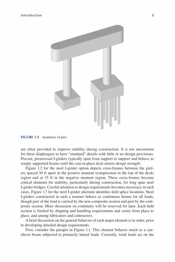
are often provided to improve stability during construction. It is not uncommon for these diaphragms to have “standard” details with little or no design provisions. Precast, prestressed I-girders typically span from support to support and behave as simply supported beams until the cast-in-place deck attains design strength.
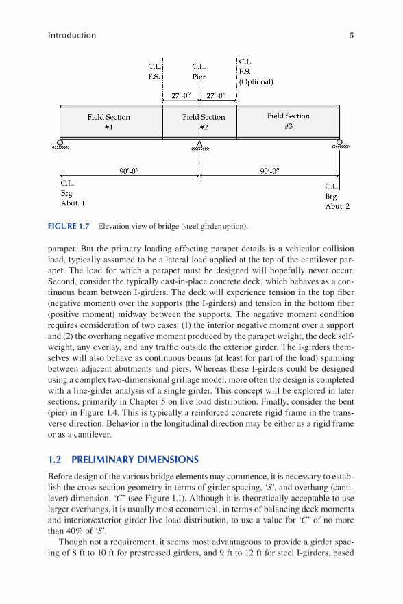
Figure 1.2 for the steel I-girder option depicts cross-frames between the gird-ers spaced 30 ft apart in the positive moment (compression in the top of the deck) region and at 15 ft in the negative moment region. These cross-frames become critical elements for stability, particularly during construction, for long span steel I-girder bridges. Careful attention to design requirements becomes necessary in such cases. Figure 1.7 for the steel I-girder alternate identifies field splice locations. Steel I-girders constructed in such a manner behave as continuous beams for all loads, though part of the load is carried by the non-composite section and part by the com-posite section. More discussion on continuity will be reserved for later. Each field section is limited by shipping and handling requirements and varies from place to place, and among fabricators and contractors.
A brief discussion on the general behavior of each major element is in order, prior to developing detailed design requirements.
First, consider the parapet in Figure 1.1. This element behaves much as a can-tilever beam subjected to primarily lateral loads. Certainly, wind loads act on the
FIGURE 1.4 Isometric of pier.

4 LRFD Bridge Design
FIGURE 1.6 Isometric of entire bridge.
FIGURE 1.5 Basic pier dimensions (preliminary).
5Introduction
parapet. But the primary loading affecting parapet details is a vehicular collision load, typically assumed to be a lateral load applied at the top of the cantilever par-apet. The load for which a parapet must be designed will hopefully never occur. Second, consider the typically cast-in-place concrete deck, which behaves as a con-tinuous beam between I-girders. The deck will experience tension in the top fiber (negative moment) over the supports (the I-girders) and tension in the bottom fiber (positive moment) midway between the supports. The negative moment condition requires consideration of two cases: (1) the interior negative moment over a support and (2) the overhang negative moment produced by the parapet weight, the deck self-weight, any overlay, and any traffic outside the exterior girder. The I-girders them-selves will also behave as continuous beams (at least for part of the load) spanning between adjacent abutments and piers. Whereas these I-girders could be designed using a complex two-dimensional grillage model, more often the design is completed with a line-girder analysis of a single girder. This concept will be explored in later sections, primarily in Chapter 5 on live load distribution. Finally, consider the bent (pier) in Figure 1.4. This is typically a reinforced concrete rigid frame in the trans-verse direction. Behavior in the longitudinal direction may be either as a rigid frame or as a cantilever.
1.2 PRELIMINARY DIMENSIONS
Before design of the various bridge elements may commence, it is necessary to estab-lish the cross-section geometry in terms of girder spacing, ‘S’, and overhang (canti-lever) dimension, ‘C’ (see Figure 1.1). Although it is theoretically acceptable to use larger overhangs, it is usually most economical, in terms of balancing deck moments and interior/exterior girder live load distribution, to use a value for ‘C’ of no more than 40% of ‘S’.
Though not a requirement, it seems most advantageous to provide a girder spac-ing of 8 ft to 10 ft for prestressed girders, and 9 ft to 12 ft for steel I-girders, based
FIGURE 1.7 Elevation view of bridge (steel girder option).
6 LRFD Bridge Design
on experience. Certainly, girder spacing outside these ranges has been adopted suc-cessfully on many projects.
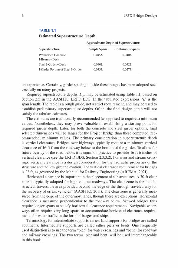
Required superstructure depths, Dss, may be estimated using Table 1.1, based on Section 2.5 in the AASHTO LRFD BDS. In the tabulated expressions, ‘L’ is the span length. The table is a rough guide, not a strict requirement, and may be used to establish preliminary superstructure depths. Often, the final design depth will not satisfy the tabular estimates.
The estimates are traditionally recommended (as opposed to required) minimum values. Nonetheless, they may prove valuable in establishing a starting point for required girder depth. Later, for both the concrete and steel girder options, final selected dimensions will be larger for the Project Bridge than these computed, rec-ommended, minimum values. The primary consideration in superstructure depth is vertical clearance. Bridges over highways typically require a minimum vertical clearance of 16 ft from the roadway below to the bottom of the girder. To allow for future overlay of the road below, it is common practice to provide 16 ft 6 inches of vertical clearance (see the LRFD BDS, Section 2.3.3.2). For river and stream cross-ings, vertical clearance is a design consideration for the hydraulic properties of the structure and the low girder elevation. The vertical clearance requirement for bridges is 23 ft, as governed by the Manual for Railway Engineering (AREMA, 2021).
Horizontal clearance is important in the placement of substructures. A 30-ft clear zone is typically adopted for high-volume roadways. The clear zone is the “unob-structed, traversable area provided beyond the edge of the through-traveled way for the recovery of errant vehicles” (AASHTO, 2011). The clear zone is generally mea-sured from the edge of the outermost lanes, though there are exceptions. Horizontal clearance is measured perpendicular to the roadway below. Skewed bridges thus require longer spans to satisfy horizontal clearance requirements. Navigable water-ways often require very long spans to accommodate horizontal clearance require-ments for water traffic in the form of barges and ships.
Terminology for intermediate supports varies. End supports for bridges are called abutments. Intermediate supports are called either piers or bents. One frequently used distinction is to use the term “pier” for water crossings and “bent” for roadway and railway crossings. The two terms, pier and bent, will be used interchangeably in this book.
TABLE 1.1Estimated Superstructure Depth
Superstructure
Approximate Depth of Superstructure
Simple Spans Continuous Spans
Prestressed ConcreteI-Beams + Deck
0.045L 0.040L
Steel I-Girder + Deck 0.040L 0.032L
I-Girder Portion of Steel I-Girder 0.033L 0.027L
7Introduction
1.3 BRIDGE GIRDER BEHAVIOR AT VARIOUS STAGES OF CONSTRUCTION
Although there are exceptions, prestressed girder bridges are typically constructed so as to behave as follows:
• non-continuous and non-composite for self-weight, deck weight, intermedi-ate diaphragms, and construction live loads
• continuous and composite for parapets, sidewalks, future overlay, and traffic
Once again, there are exceptions, but steel I-girder bridges, on the other hand, are typically designed and constructed so as to behave:
• continuous and non-composite for self-weight, deck weight, cross frames, lateral bracing, and construction live loads
• continuous and long-term composite for parapet, sidewalks, future overlay, and utilities
• continuous and short-term composite for traffic
Long-term composite properties for steel I-girders are computed using steel as the primary material with a modular ratio of 3n applied to concrete. Short-term composite properties for steel I-girders are computed using a modular ratio, n = ES/EC (ratio of steel to concrete Young’s modulus). The long-term property calculations are intended to account for creep under permanent loads, while research has shown that short-term properties are more appropriate for transient loads.
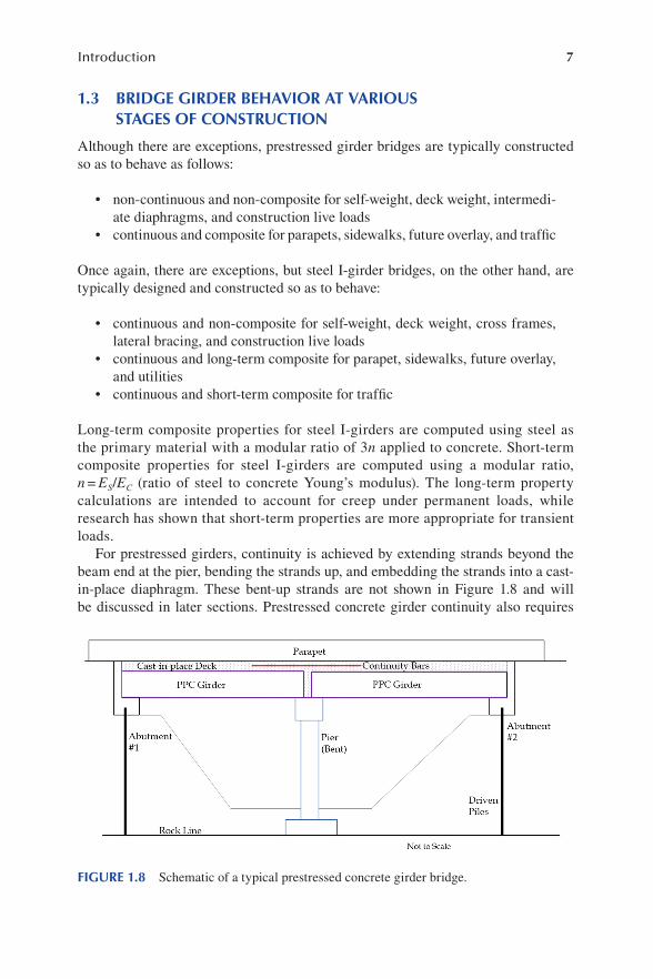
For prestressed girders, continuity is achieved by extending strands beyond the beam end at the pier, bending the strands up, and embedding the strands into a cast-in-place diaphragm. These bent-up strands are not shown in Figure 1.8 and will be discussed in later sections. Prestressed concrete girder continuity also requires
FIGURE 1.8 Schematic of a typical prestressed concrete girder bridge.

8 LRFD Bridge Design
relatively heavy longitudinal reinforcement in the deck to resist negative moments at interior supports.
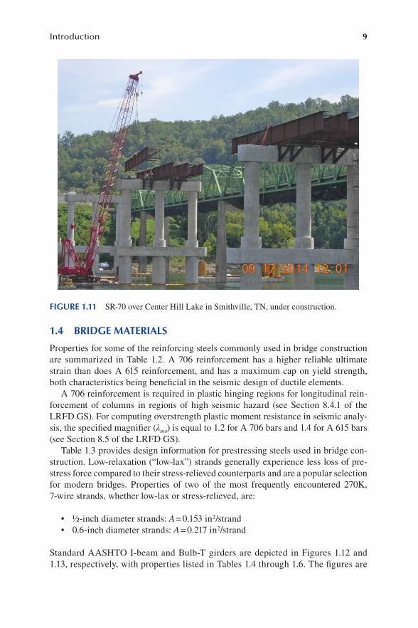
Figures 1.8 and 1.9 are schematic depictions of typical prestressed concrete and steel I-girder bridges, respectively. Figures 1.10 and 1.11 are photographs of actual structures under construction.
FIGURE 1.9 Schematic of a typical steel I-beam bridge.
FIGURE 1.10 Demonbreun Street Viaduct in Nashville, TN, under construction.
9Introduction
1.4 BRIDGE MATERIALS
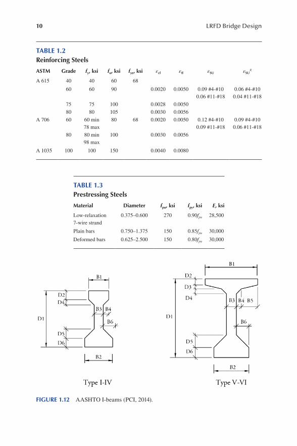
Properties for some of the reinforcing steels commonly used in bridge construction are summarized in Table 1.2. A 706 reinforcement has a higher reliable ultimate strain than does A 615 reinforcement, and has a maximum cap on yield strength, both characteristics being beneficial in the seismic design of ductile elements.
A 706 reinforcement is required in plastic hinging regions for longitudinal rein-forcement of columns in regions of high seismic hazard (see Section 8.4.1 of the LRFD GS). For computing overstrength plastic moment resistance in seismic analy-sis, the specified magnifier (λmo) is equal to 1.2 for A 706 bars and 1.4 for A 615 bars (see Section 8.5 of the LRFD GS).
Table 1.3 provides design information for prestressing steels used in bridge con-struction. Low-relaxation (“low-lax”) strands generally experience less loss of pre-stress force compared to their stress-relieved counterparts and are a popular selection for modern bridges. Properties of two of the most frequently encountered 270K, 7-wire strands, whether low-lax or stress-relieved, are:
• ½-inch diameter strands: A = 0.153 in2/strand• 0.6-inch diameter strands: A = 0.217 in2/strand
Standard AASHTO I-beam and Bulb-T girders are depicted in Figures 1.12 and 1.13, respectively, with properties listed in Tables 1.4 through 1.6. The figures are
FIGURE 1.11 SR-70 over Center Hill Lake in Smithville, TN, under construction.
10 LRFD Bridge Design
TABLE 1.2Reinforcing Steels
ASTM Grade fy, ksi fu, ksi fye, ksi εcl εtl εSU εSUR
A 615 40 40 60 68
60 60 90 0.0020 0.0050 0.09 #4-#100.06 #11-#18
0.06 #4-#100.04 #11-#18
75 75 100 0.0028 0.0050
80 80 105 0.0030 0.0056
A 706 60 60 min78 max
80 68 0.0020 0.0050 0.12 #4-#100.09 #11-#18
0.09 #4-#100.06 #11-#18
80 80 min98 max
100 0.0030 0.0056
A 1035 100 100 150 0.0040 0.0080
TABLE 1.3Prestressing Steels
Material Diameter fpu, ksi fpy, ksi E, ksi
Low-relaxation7-wire strand
0.375–0.600 270 0.90fpu 28,500
Plain bars 0.750–1.375 150 0.85fpu 30,000
Deformed bars 0.625–2.500 150 0.80fpu 30,000
FIGURE 1.12 AASHTO I-beams (PCI, 2014).

11Introduction
FIGURE 1.13 AASHTO bulb-T beams (PCI, 2014).
TABLE 1.4Concrete I-beam Dimensions (inches)
Type D1 D2 D3 D4 D5 D6 B1 B2 B3 B4 B5 B6
I 28 4 0 3 5 5 12 16 6 3 0 5
II 36 6 0 3 6 6 12 18 6 3 0 6
III 45 7 0 4.5 7.5 7 16 22 7 4.5 0 7.5
IV 54 8 0 6 9 8 20 26 8 6 0 9
V 63 5 3 4 10 8 42 28 8 4 13 10
VI 72 5 3 4 10 8 42 28 8 4 13 10
12 LRFD Bridge Design
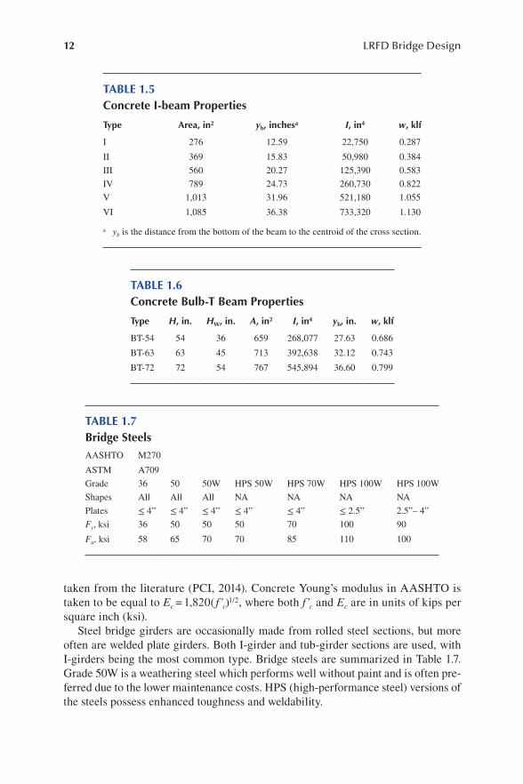
taken from the literature (PCI, 2014). Concrete Young’s modulus in AASHTO is taken to be equal to Ec = 1,820( f’c)1/2, where both f’c and Ec are in units of kips per square inch (ksi).
Steel bridge girders are occasionally made from rolled steel sections, but more often are welded plate girders. Both I-girder and tub-girder sections are used, with I-girders being the most common type. Bridge steels are summarized in Table 1.7. Grade 50W is a weathering steel which performs well without paint and is often pre-ferred due to the lower maintenance costs. HPS (high-performance steel) versions of the steels possess enhanced toughness and weldability.
TABLE 1.5Concrete I-beam Properties
Type Area, in2 yb, inchesa I, in4 w, klf
I 276 12.59 22,750 0.287
II 369 15.83 50,980 0.384
III 560 20.27 125,390 0.583
IV 789 24.73 260,730 0.822
V 1,013 31.96 521,180 1.055
VI 1,085 36.38 733,320 1.130
a yb is the distance from the bottom of the beam to the centroid of the cross section.
TABLE 1.6Concrete Bulb-T Beam Properties
Type H, in. HW, in. A, in2 I, in4 yb, in. w, klf
BT-54 54 36 659 268,077 27.63 0.686
BT-63 63 45 713 392,638 32.12 0.743
BT-72 72 54 767 545,894 36.60 0.799
TABLE 1.7Bridge SteelsAASHTO M270
ASTM A709
Grade 36 50 50W HPS 50W HPS 70W HPS 100W HPS 100W
Shapes All All All NA NA NA NA
Plates ≤ 4” ≤ 4” ≤ 4” ≤ 4” ≤ 4” ≤ 2.5” 2.5”– 4”
Fy, ksi 36 50 50 50 70 100 90
Fu, ksi 58 65 70 70 85 110 100
13Introduction
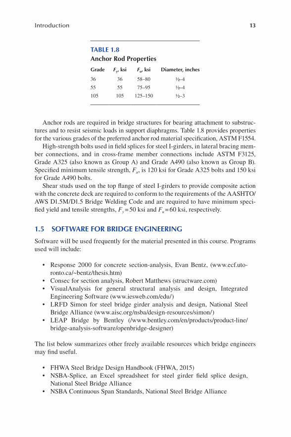
Anchor rods are required in bridge structures for bearing attachment to substruc-tures and to resist seismic loads in support diaphragms. Table 1.8 provides properties for the various grades of the preferred anchor rod material specification, ASTM F1554.
High-strength bolts used in field splices for steel I-girders, in lateral bracing mem-ber connections, and in cross-frame member connections include ASTM F3125, Grade A325 (also known as Group A) and Grade A490 (also known as Group B). Specified minimum tensile strength, Fu, is 120 ksi for Grade A325 bolts and 150 ksi for Grade A490 bolts.
Shear studs used on the top flange of steel I-girders to provide composite action with the concrete deck are required to conform to the requirements of the AASHTO/AWS D1.5M/D1.5 Bridge Welding Code and are required to have minimum speci-fied yield and tensile strengths, Fy = 50 ksi and Fu = 60 ksi, respectively.
1.5 SOFTWARE FOR BRIDGE ENGINEERING
Software will be used frequently for the material presented in this course. Programs used will include:
• Response 2000 for concrete section-analysis, Evan Bentz, (www .ecf .uto-ronto .ca/ ~bentz /thesis .htm)
• Consec for section analysis, Robert Matthews (structware .c om)• VisualAnalysis for general structural analysis and design, Integrated
Engineering Software (www .iesweb .com /edu/)• LRFD Simon for steel bridge girder analysis and design, National Steel
Bridge Alliance (www .aisc .org /nsba /design -resources /simon/)• LEAP Bridge by Bentley (/www .bentley .com /en /products /product -line /
bridge -analysis -software /openbridge -designer)
The list below summarizes other freely available resources which bridge engineers may find useful.
• FHWA Steel Bridge Design Handbook (FHWA, 2015)• NSBA-Splice, an Excel spreadsheet for steel girder field splice design,
National Steel Bridge Alliance• NSBA Continuous Span Standards, National Steel Bridge Alliance
TABLE 1.8Anchor Rod Properties
Grade Fy, ksi Fu, ksi Diameter, inches
36 36 58–80 ½–4
55 55 75–95 ½–4
105 105 125–150 ½–3

14 LRFD Bridge Design
• PCI Bridge Design Manual (PCI, 2014)• WSDOT BridgeLink Bridge Engineering Software, Washington State
Department of Transportation
1.6 SECTION PROPERTIES
The calculation of composite section properties for bridge girders is based on theory typically learned in courses dealing with mechanics of materials, advanced steel design, and reinforced concrete, each of which is a pre-requisite to a full appreciation of this course. Deflection calculations for simple beams is covered in undergraduate structural mechanics courses. Section property calculations for composite sections are needed in all cases for modern bridge girders, both steel and prestressed con-crete. Exercises for Chapter 1 focus on examples of such calculations, in addition to girder spacing and overhang issues discussed in the Introduction. For additional information on the calculation of plastic moments, the reader is referred to Appendix D6 of the LRFD BDS (AASHTO, 2020).
Recall that section property calculations for cross-sections composed of more than one material require the selection of a base material. For reinforced concrete design, concrete is selected as the base material with steel areas multiplied by the modular ratio (n) to obtain an equivalent concrete cross section. Subsequent stress calculations for the steel component require amplification by n. With steel plate gird-ers, the reverse approach is adopted. Concrete is transformed into an equivalent steel area via division by the modular ratio. Subsequent stress calculations for the concrete components require division by n.
1.7 SOLVED PROBLEMS
Problem 1.1 Establish an approximate girder spacing and approximate girder depth for
both the concrete and steel girder options for the Project Bridge. The deck thickness is 8.25 inches and the thickness of the haunch (the gap between the top of the girder and the bottom of the deck) is 1.75 inches.
Problem 1.2 For the concrete option on the Project Bridge, suppose a prestress force
equal to 929 kips is applied to the girder as a compressive axial force at each end. Select a BT-54 girder and determine the midspan deflection due to girder self-weight and the applied axial prestress force. The prestress force is applied 4.53 inches above the bottom of the girder, thus producing not only an axial force, but also a negative moment (tension in the top of the girder) due to eccentric application. Assume the girder behaves as a simple span and is 87-ft 9-in long. Concrete strength is f’c = 7 ksi. Ignore second-order effects of the axial load on deflections.
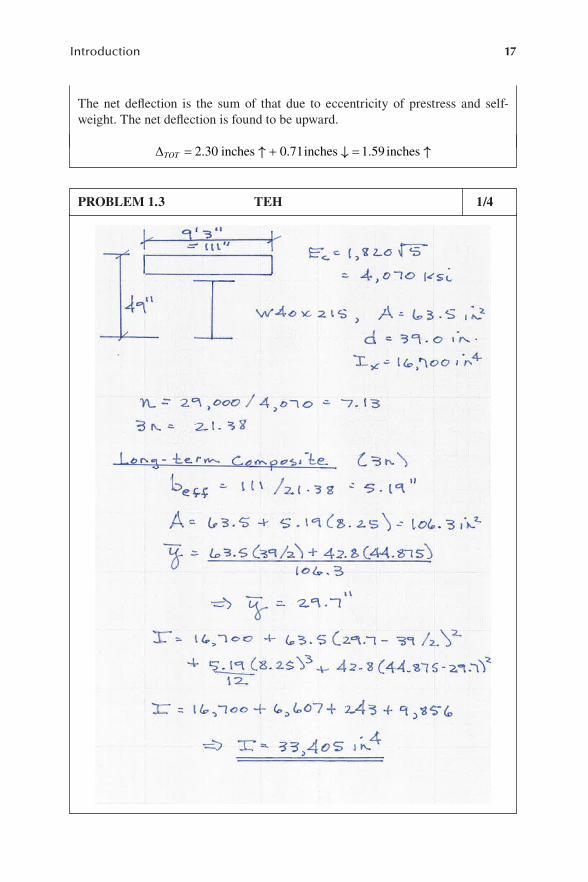
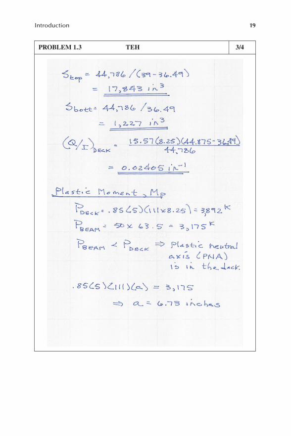
Problem 1.3 For the steel girder option of the Project Bridge, determine the compos-
ite properties (both short-term and long-term) for the elastic condition for an interior girder. Determine the plastic moment of the composite section in positive flexure (deck in compression). Use a W40 × 215 rolled beam girder,

15Introduction
8.25-inch deck, 1.75-inch haunch (distance from the top of the girder to the bottom of the deck in this case), and Grade 50 steel. Deck concrete has a specified minimum 28-day compressive strength, f’c of 5 ksi.
PROBLEM 1.1 TEH 1/2
The following calculation shows that a girder spacing of no less than 9.057 feet is required to meet the overhang rule-of-thumb for the Project Bridge.
3 2 34 417S C+ = . feet
3 2 0 4 34 417 9 057S S S+ ( ) = ¢ ® =. . . feet
Select S = 9 feet 3 inches with a corresponding C = 3 feet 4 inches for the Project Bridge.
Define the following:
• (Dss)PPC is the superstructure depth for the prestressed girder option.• (DBM)PPC is the girder depth for the prestressed girder option.• (Dss)SG is the superstructure depth for the steel girder option.• (DBM)SG is the girder depth for the steel girder option.
The superstructure depth is the girder depth plus the haunch depth plus the deck thickness.
For the precast, prestressed concrete girder option, assume continuous spans and use the information from Table 1.1.
Dss PPC( ) » ´ = =0 040 90 3 6 43. . ft inches
Whereas (Dss)PPC is, strictly speaking, the total depth of (a) the prestressed con-crete girder, (b) the haunch, and (c) the deck, experience has shown that the girder depth alone should be approximately equal to the calculated value for optimal design of prestressed girders, in the author’s opinion. Without question, the esti-mate is just that, an estimate, and many successful projects have incorporated depths both smaller and larger.
PROBLEM 1.1 TEH 2/2
DBM PG( ) ³ 43 inches
For the steel I-girder option, two criteria are specified in Table 1.1. Assess both and choose the larger value as the initial superstructure depth estimate.
For the steel I-girder plus deck criteria:
Dss SG( ) » ´ = =0 032 90 2 88 34 6. . .ft inches
DBM SG( ) = - - =34 6 8 25 1 75 24 6. . . . inches

16 LRFD Bridge Design
For the steel I-girder alone:
DBM SG( ) » ´ = = ¬0 027 90 2 43 29 2. . .ft inches controls
DBM SG( ) ³ ¬29 2. inches controls
PROBLEM 1.2 TEH 1/2
For a BT-54 girder, obtain the properties from Table 1.6.
A = 659 2in
I = 268 077 4, in
yb = 27 63. inches
w = 0 686. klf
The eccentricity of the applied axial force may now be computed.
e = - =27 63 4 53 23 1. . . inches
The modulus of elasticity for concrete, Ec, is needed for deflection calculations.
EC = =1 820 7 4 815, , ksi
The end moment is equal to the applied force multiplied by the eccentricity. Since this moment is negative, the deflection resulting from the moment is upward. The conjugate beam method can be used to determine the deflection due to applied end moments in a simply supported beam.
DPSPS
C
M L
E I=
2
8
MPS = ´ =929 23 1 21 460. , inches kips
DPS =( ) ´( )( )( )
=21 460 87 75 12
8 4 815 268 0772 30
2, .
, ,. inches
PROBLEM 1.2 TEH 2/2
The deflection at midspan due to self-weight, a uniformly distributed load, may be determined from the conjugate beam method, double integration of the moment equation, or from standard textbook formulas.
DSWC
wL
E I= =
æèç
öø÷ ´( )
( )(5
384
50 686
1287 75 12
384 4 815 268 077
4
4..
, , ))= ¯0 71. inches
17Introduction
The net deflection is the sum of that due to eccentricity of prestress and self-weight. The net deflection is found to be upward.
DTOT = + =2 30 0 71 1 59. . .inches inches inches↑ ↓ ↑
PROBLEM 1.3 TEH 1/4

18 LRFD Bridge Design
PROBLEM 1.3 TEH 2/4
19Introduction
PROBLEM 1.3 TEH 3/4

20 LRFD Bridge Design
PROBLEM 1.3 TEH 4/4
1.8 EXERCISES
E1.1. A three-span continuous, 129-ft 3-inches-wide interstate bridge consists of
95-ft end spans with a 156-ft center span for a total length of 346 feet. Estimate the girder depth required if (a) prestressed concrete girders are used and (b) steel I-girders are used. Also, determine the number of beams and beam spacing for each girder type.
For the prestressed girder option, use a girder spacing between 8 feet and 10 feet. For the steel I-girder option, use a girder spacing between 9 feet and 12 feet. Use a deck thickness of 8.25 inches.
E1.2. A five-span continuous, 34-ft-wide bridge consists of 270-ft end spans and
three 335-ft interior spans for a total length of 1,545 feet. Establish a pre-liminary cross-section (number of girders, girder spacing, and overhang dimension) configuration and steel I-girder depth for the bridge. To mini-mize the number of girders, use a target girder spacing of 12 feet. Deck thickness is 9 inches.
21Introduction
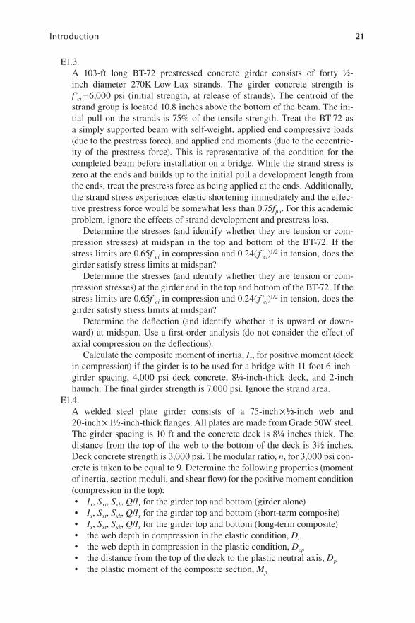
E1.3. A 103-ft long BT-72 prestressed concrete girder consists of forty ½-
inch diameter 270K-Low-Lax strands. The girder concrete strength is f’ci = 6,000 psi (initial strength, at release of strands). The centroid of the strand group is located 10.8 inches above the bottom of the beam. The ini-tial pull on the strands is 75% of the tensile strength. Treat the BT-72 as a simply supported beam with self-weight, applied end compressive loads (due to the prestress force), and applied end moments (due to the eccentric-ity of the prestress force). This is representative of the condition for the completed beam before installation on a bridge. While the strand stress is zero at the ends and builds up to the initial pull a development length from the ends, treat the prestress force as being applied at the ends. Additionally, the strand stress experiences elastic shortening immediately and the effec-tive prestress force would be somewhat less than 0.75fpu. For this academic problem, ignore the effects of strand development and prestress loss.
Determine the stresses (and identify whether they are tension or com-pression stresses) at midspan in the top and bottom of the BT-72. If the stress limits are 0.65f’ci in compression and 0.24( f’ci)1/2 in tension, does the girder satisfy stress limits at midspan?
Determine the stresses (and identify whether they are tension or com-pression stresses) at the girder end in the top and bottom of the BT-72. If the stress limits are 0.65f’ci in compression and 0.24( f’ci)1/2 in tension, does the girder satisfy stress limits at midspan?
Determine the deflection (and identify whether it is upward or down-ward) at midspan. Use a first-order analysis (do not consider the effect of axial compression on the deflections).
Calculate the composite moment of inertia, Ix, for positive moment (deck in compression) if the girder is to be used for a bridge with 11-foot 6-inch-girder spacing, 4,000 psi deck concrete, 8¼-inch-thick deck, and 2-inch haunch. The final girder strength is 7,000 psi. Ignore the strand area.
E1.4. A welded steel plate girder consists of a 75-inch × ½-inch web and
20-inch × 1½-inch-thick flanges. All plates are made from Grade 50W steel. The girder spacing is 10 ft and the concrete deck is 8¼ inches thick. The distance from the top of the web to the bottom of the deck is 3½ inches. Deck concrete strength is 3,000 psi. The modular ratio, n, for 3,000 psi con-crete is taken to be equal to 9. Determine the following properties (moment of inertia, section moduli, and shear flow) for the positive moment condition (compression in the top):• Ix, Sxt, Sxb, Q/Ix for the girder top and bottom (girder alone)• Ix, Sxt, Sxb, Q/Ix for the girder top and bottom (short-term composite)• Ix, Sxt, Sxb, Q/Ix for the girder top and bottom (long-term composite)• the web depth in compression in the elastic condition, Dc
• the web depth in compression in the plastic condition, Dcp
• the distance from the top of the deck to the plastic neutral axis, Dp
• the plastic moment of the composite section, Mp
22 LRFD Bridge Design
E1.5. For negative moments (tension in the top), determine the composite section
properties for the girder in problem E1.4. if the area of steel in the deck is 10.00 in2 with fy = 60 ksi, located 3½ inches from the top of the deck.
E1.6. A welded steel plate girder consists of a 42-inch × ½-inch web and
16-inch × 1-inch thick flanges. All plates are made from Grade 50W steel. The girder spacing is 10 ft and the concrete deck is 8¼ inches thick. The distance from the top of the web to the bottom of the deck is 3½ inches. Deck concrete strength is 4,000 psi. The modular ratio, n, for 4,000 psi concrete is taken to be equal to 8. Determine the distance from the top of the deck to the plastic neutral axis (PNA) and the composite plastic moment in positive bending, Mp.
E1.7. Estimate the total superstructure weight (kips per foot) for the Project
Bridge. For the concrete girder option, use BT-54 girders. For the steel girder option, use W40 × 215 rolled steel beams. Deck thickness is 8.25 inches. Haunch thickness is 1.75 inches. Each parapet requires 0.0926 cubic yards of concrete per linear foot.
E1.8. For the concrete girder option of the Project Bridge, estimate the total verti-
cal reaction at the intermediate pier due to all dead loads.
References AASHTO , 2011. Guide Specifications for LRFD Seismic Bridge Design. 2nd ed. Shington, D.C.:American Association of State Highway and Transportation Officials. AASHTO , 2014. Guide Specifications for Seismic Isolation Design. 4th ed. Washington, D.C.:American Association of State Highway and Transportation Officials. AASHTO , 2017. LRFD Bridge Construction Specifications. Washington, D.C.: AmericanAssociation of State Highway and Transportation Officials. AASHTO , 2020. LRFD Bridge Design Specifications. 9th ed. Washington, D.C.: AmericanAssociation of State Highway and Transportation Officials. AISC , 2016. AISC 360-16: Specification for Structural Steel Buildings. Chicago, IL: AmericanInstitute of Steel Construction. AREMA , 2021. Manual for Railway Engineering. Landover, MD: American Railway Engineeringand Maintenance-of-Way Association. Atkinson, G. & Beresnev, I. A. , 2002. Ground Motions at Memphis and St. Louis from M7.5–8.0 Earthquakes in the New Madrid Seismic Zone. Bulletin of the Seismological Society ofAmerica, 92(3), pp. 1015–1024. Buckle, I. , Constantinou, M. , Dicleli, M. & Ghasemi, H. , 2006. Seismic Isolation of HighwayBridges (MCEER-06-SP07), Buffalo, NY: Multidisciplinary Center for Earthquake EngineeringResearch. Buckle, I. et al., 2006. Seismic Retrofitting Manual for Highway Bridges (FHWA-HRT-06-032),McLean, VA: Federal Highway Administration. Bunner, M. , 2015. Steel Bridge Design Handbook: Splice Design, Washington, D.C.: FederalHighway Administration. City of Los Angeles Harbor Department , 2010. Code for Seismic Design, Upgrade and Repairof Container Wharves, The Port of Los Angeles. Computers and Structures, Inc ., 2016. CSiBridge Version 18.2.0, Berkeley, CA: sn. Fernández, J. A. , 2007. Numerical Simulation of Earthquake Ground Motions in the UpperMississippi Embayment, Doctoral Dissertation, Atlanta, GA: Georgia Institute of Technology. Feygin, V. B. , 2015. Performance Based Design of Wharves with Steel Pipe Piles. GlobalJournal of Researches in Engineering: Civil and Structural Engineering, 15(3), pp. 1–16. FHWA , 2015. Steel Bridge Design Handbook. Washington, DC: Federal HighwayAdministration. FIP Industriale , 2011. Lead Rubber Bearings Product Catalog, Selvazanno, Italy: FIPIndustriale. Fulmer, S. J. , Kowalsky, M. J. & Nau, J. M. , 2013. Seismic Performance of Steel Pipe Pile toCap Beam Moment Resisting Connections, Raleigh, NC: North Carolina State University. Giannopoulos, D. & Vamvatsikos, D. , 2018. Ground Motion Records for Seismic PerformanceAssessment: To Rotate ot not to Rotate. Earthquake Engineering and Structural Dynamics,47(12), pp. 2410–2425. Grubb, M. A. , Frank, K. H. & Ocel, J. M. , 2018. Bolted Field Splices for Steel Bridge FlexuralMembers, American Institute of Steel Construction / National Steel Bridge Alliance. Gulkan, P. & Sozen, M. A. , 1974. Inelastic Response of Reinforced Concrete Structures toEarthquake Ground Motions. Journal of the American Concrete Institute, 71(12), pp. 604–610. Hadjian, A. H. , 1981. On the Correlation of the Components of Strong Motion - Part 2. Bulletinof the Seismological Society of America, 71(4), pp. 1323–1331. Hajihashemi, A. , Pezeshk, S. & Huff, T. , 2017. A Comparison of Nonlinear Static Proceduresand Modeling Assumptions for Seismic Design of Ordinary Bridges. ASCE Practice Periodicalon Structural Design and Construction, 22(2), pp. 1–10. Hallmark, R. , 2006. Low Cycle Fatigue of Steel Piles in Integral Abutment Bridges, Lulea,Sweden: Lulea University of Science anf Technology. Harn, R. , Ospina, C. E. & Pachakis, D. , 2019. Proposed Pipe Pile Strain Limits for ASCE 61-19. American Society of Civil Engineers, pp. 437–448. Hashash, Y. M. A. , Tsai, C. C. , Phillips, C. & Park, D. , 2008. Soil-Column Depth-DependentSeismic Site Coefficeints and Hazard Maps for the Upper Mississippi Embayment. Bulletin ofthe Seismological Society of America, 98(4), pp. 2004–2021. Helwig, T. & Yura, J. , 2015. Steel Bridge Design Handbook: Bracing System Design,Washington, D.C.: Federal Highway Administration.

Huff, T. , 2014. Spanning the Wolf River Wetlands. ASPIRE - The Concrete Magazine, pp.14–17. Huff, T. , 2016a. Partial Isolation as a Seismic Design Strategy for Pile Bent Bridges in the NewMadrid Seismic Zone. ASCE Practice Periodical on Structural Design and Construction, 21(2),pp. 1–12. Huff, T. , 2016b. Seismic Displacement Estimates for Bridges in the New Madrid Seismic Zone.ASCE Practice Periodical on Structural Design and Construction, May, 21(2), pp. 1–9. Huff, T. , 2016c. Structural Demand on Bridges Subjected to Bidirectional Ground Motions.ASCE Practice Periodical on Structural Design and Construction, 22(1), pp. 1–13. Huff, T. & Pezeshk, S. , 2016. Inelastic Displacement Spectra for Bridges Using the SubstituteStructure Method. ASCE Practice Periodical on Structural Design and Construction, 21(2), pp.1–13. Huff, T. & Shoulders, J. , 2017. Partial Isolation of a Bridge on Interstate 40 in the New MadridSeismic Zone, National Harbor, MD: Engineers Society of Western Pennsylvania. Kawashima, K. , 2004. Seismic Isolation of Highway Bridges. Journal of Japan Association forEarthquake Engineering, 4( 3, Special Issue), pp. 283–297. Kottke, A. & Rathje, E. M. , 2008. A Semi-Automated Procedure for Selecting and ScalingRecorded Earthquake Motions for Dynamic Analysis. Earthquake Spectra, 24(4), pp. 911–932. Kramer, S. L. , Arduino, P. & Sideras, S. S. , 2012. Earthquake Ground Motion Selection,Seattle, WA: Washington State Department of Transportation. Lehman, D. & Roeder, C. W. , 2012. An Initial Study into the use of Concrete Filled Steel Tubesfor Bridge Piers and Foundation Connections, Seattle, WA: The university of Washington. Malekmohammadi, M. & Pezeshk, S. , 2014. Nonlinear Site Amplification Factors for SitesLocated within the Mississippi Embayment with Consideration for Deep Soil Deposit.Earthquake Spectra. Maurer , 2011. Seismic Isolation Systems with Lead Rubber Bearings, Munich, Germany:Maurer Sohne. Miller, R. A. , Castrodale, R. , Mirmiran, A. & Hastak, M. , 2004. NCHRP Report 519:Connection of Simple-Span Precast Concrete Girders for Continuity, Washington, D.C.:National Academies of Science, Engineering and Medicine. Moon, S. w. , Hashash, Y. M. A. & Park, D. , 2016. USGS Hazard Map Compatible Depth-Dependent Seismic Site Coefficients for the Upper Mississippi Embayment. KSCE Journal ofCivil Engineering, 21, pp. 1220–1231. National Academies of Sciences, Engineering, and Medicine , 2021. Proposed Modification toAASHTO Cross-Frame Analysis and Design, Washington, D.C.: The National AcademiesPress. NEHRP Consultants Joint Venture , 2011. Selecting and Scaling Earthquake Ground Motions:NIST GCR 11-917-15, Redwood City, California: National Institute of Standards andTechnology. Pacific Earthquake Engineering Research Center , 2014. PEER Ground Motion Database.[Online]; Available at: http://ngawest2.berkeley.edu/ [Accessed 5 May 2017]. PCI , 2014. Bridge Design Manual, Chicago, IL: Precast Prestressed Concrete Institute. PEER , 2010. Technical Report for the PEER Ground Motion Database Web Application.Berkeley, CA: Pacific Earthquake Engineering Research Center. Pietra, G. M. , Calvi, G. M. & Pinho, R. , 2008. Displacement-Based Seismic Design of IsolatedBridges, Research Report ROSE - 2008/01. 1st ed. Pavia, Italy: IUSS Press. POLA , 2010. The Port of Los Angeles Code for Seismic Design, Upgrade and Repair ofContainer Wharves, Los Angeles, CA: Port of Los Angeles. POLB , 2015. Port of Long Beach Wharf Design Criteria, Long Beach, CA: Port of Long Beach. Port of Long Beach , 2012. Wharf Design Criteria, s.l.: sn. Priestley, M. J. N. , Calvi, G. M. & Kowalsky, M. J. , 2007. Displacement-Based Seismic Designof Structures. 1st ed. Pavia, Italy: IUSS Press. Priestley, M. J. N. & Grant, D. N. , 2005. Viscous Damping in Seismic Design and Analysis.Journal of Earthquake Engineering - Imperial College Press, 9, pp. 229–255. Priestley, M. J. N. , Seible, F. & Calvi, G. M. , 1996. Seismic Design and Retrofit of Bridges. 1sted. New York, NY: John Wiley & Sons. Robinson Seismic LTD , 2011. Catalog of Robinson Seismic Bearings, Petone, New Zealand:Robinson Seismic LTD.

Rollins, K. M. & Stenlund, T. E. , 2008. Laterally Loaded Pile Cap Connections, Provo, Utah:Brigham Young University. Romero, S. M. & Rix, G. J. , 2005. Ground Motion Amplification of Soils in the Upper MississippiEmbayment, Urbana, IL: NSF/MAE Center. SeismoSoft , 2020a. SeismoArtif 2020. [Online]; Available at:http://seismosoft.com/en/SeismoArtif.aspx SeismoSoft , 2020b. SeismoMatch 2020. [Online]; Available at:http://seismosoft.com/en/SeismoMatch.aspx Silva, P. F. & Seible, F. , 1999. Design Example of a Multiple Column Bridge Bent UnderSeismic Loads Using the Alaska Cast-in-Place Steel Shell, San Diego, CA: University ofCalifornia. Silva, P. F. & Sritharan, S. , 2011. Seismic Performance of a Concrete Bridge Bent Consistingof Three Steel Shell Columns. Earthquake Spectra, 27(1), pp. 107–132. Stafford, P. J. , Mendis, R. & Bommer, J. J. , 2008. Dependence of Damping Correction Factorsfor Response Spectra on Duration and Number of Cycles. ASCE Journal of StructuralEngineering, 134(8), pp. 1364–1373. Stenlund, T. , 2007. Laterally Loaded Pile Cap Connections, Provo, UT: Brigham YoungUniversity. Stephens, J. & McKittrick, L. , 2005. Performance of Steel Pipe Pile-to-Concrete Bent CapConnections Subject to Seismic or High Transverse Loading: Phase II, Bozeman: MontanaState University. Stephens, M. T. , Berg, L. M. , Lehman, D. E. & Roeder, C. W. , 2016. Seismic CFST Column-to-Precast Cap Beam Connections for Accelerated Bridge Construction. ASCE Journal ofStructural Engineering, 142(9), pp. 1–14. Stevens, J. E. et al., 1998. Performance of Steel Pipe Pile-to-Concrete Bent Cap ConnectionsSubject to Seismic or High Transverse Loading: Phase I, Bozeman: Montana State University. Tsopelas, P. , Nagarajaiah, S. , Constantinou, M. C. & Reinhorn, A. M. , 1991. 3D-BASIS-M:Nonlinear Dynamic Analysis of Multiple Building Base Isolated Structures. Technical ReportNCEER-91-0014. Buffalo, NY: University of Buffalo. United States Geological Survey , 2020. USGS Unified Hazard Tool. [Online]; Available at:https://earthquake.usgs.gov/hazards/interactive/ [Accessed 6 January 2020]. USGS, CGS, ANSS , 2014. Center for Engineering Strong Motion Data. [Online]; Available at:http://strongmotioncenter.org/ Warn, G. P. , 2002. Displacement Estimates in Isolated Bridges. MCEER Student ResearchAccomplishments. Warn, G. P. & Whittaker, A. S. , 2007. Performance Estimates for Seismically Isolated Bridges(MCEER-07-0024), Buffalo, NY: Multidisciplinary Center for Earthquake Engineering Research. Watson-Lamprey, J. A. & Boore, D. M. , October 2007. Beyond SA-GMRotI: Conversion to SA-Arb, SA-SN, and SA-MaxRot. Bulletin of the Seismological Society of America, 97(5), pp.1511–1524. Wen, Y. K. , 1976. Method for Random Vibration of Hysteretic Systems. Journal of theEngineering Mechanics Division, 102, pp. 246–263. WSDOT , 2020. Bridge Design Manual, Olympia, WA: Washington State Department ofTransportation. Yura, J. A. , 2001. Fundamentals of Beam Bracing. Engineering Journal, 38, pp. 11–26.
Related Documents

![[Donald W. Taylor] Fundamentals of Soil Mechanics(BookZa.org)](https://static.cupdf.com/doc/110x72/55cf9830550346d03396205f/donald-w-taylor-fundamentals-of-soil-mechanicsbookzaorg.jpg)


![[Donald W. Taylor] Fundamentals of Soil Mechanics](https://static.cupdf.com/doc/110x72/55cf94b2550346f57ba3ce13/donald-w-taylor-fundamentals-of-soil-mechanics.jpg)