New Standard! All-Purpose Laser Sensor LR-T SERIES All-Purpose Laser Sensor Multi-Sensor Controller MU-N Series

Welcome message from author
This document is posted to help you gain knowledge. Please leave a comment to let me know what you think about it! Share it to your friends and learn new things together.
Transcript
New Standard! All-Purpose Laser Sensor
LR-TSERIES
A l l - P u r p o s e L a s e r S e n s o r
Multi-Sensor Controller MU-N Series
2
LR-TSERIES
A l l- P u r p o s eLaser Sensor
A NEW DIMENSION TO ALL-PURPOSE LASER SENSORSThe LR-T Series of refl ective sensors represents a seamless fusion of innovative technology and robust functionality. The Time of Flight (TOF) detection method and custom integrated circuit allow the LR-T Series sensors to provide consistently stable detection in all applications. Equally as impressive, this innovative technology is stored in a compact and durable metal housing for versatile installation in any environment. Lastly, the LR-T Series offers user-friendly operability to further minimize installation and set up time. All of these features combine to add a new dimension to all-purpose laser sensors.
Innovative Technology and Adaptable FeaturesSuperior Detection Capabilities
Flexible Mounting and Simplifi ed SetupEasy to Use
Utilize in Any ApplicationUnmatched Versatility
3
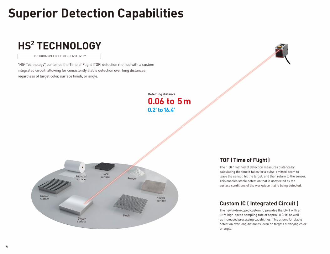
The newly-developed custom IC provides the LR-T with an ultra high-speed sampling rate of approx. 8 GHz, as well as increased processing capabilities. This allows for stable detection over long distances, even on targets of varying color or angle.
The "TOF" method of detection measures distance by calculating the time it takes for a pulse-emitted beam to leave the sensor, hit the target, and then return to the sensor. This enables stable detection that is unaffected by the surface conditions of the workpiece that is being detected.
Custom IC ( Integrated Circuit )
TOF ( Time of Flight )
"HS2 Technology" combines the Time of Flight (TOF) detection method with a custom integrated circuit, allowing for consistently stable detection over long distances, regardless of target color, surface fi nish, or angle.
HS2 TECHNOLOGY
0.06 to 5 m 0.2' to 16.4'
Detecting distance
Uneven surface
Rounded surface
Black surface
Glossy surface
Mesh
Heated surface
Powder
HS2: HIGH-SPEED & HIGH-SENSITIVITY
Superior Detection Capabilities
4
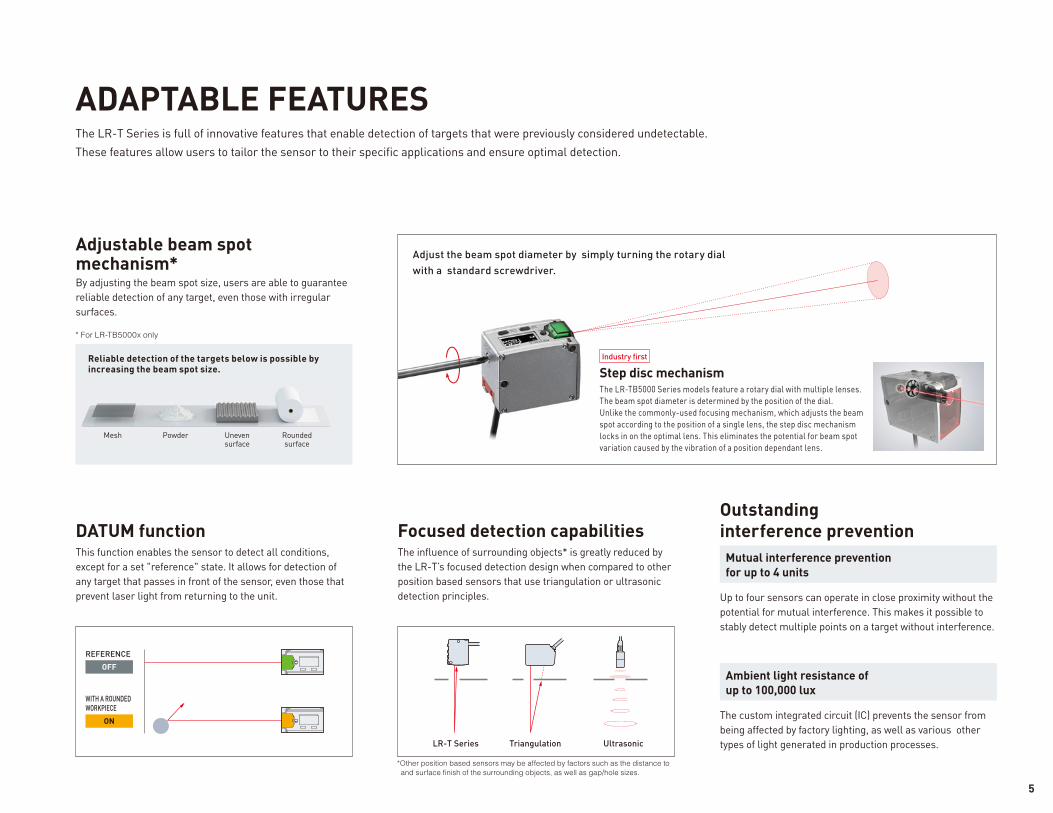
Industry fi rst
Mesh Uneven surface
Rounded surface
Powder
The LR-T Series is full of innovative features that enable detection of targets that were previously considered undetectable. These features allow users to tailor the sensor to their specifi c applications and ensure optimal detection.
Adjust the beam spot diameter by simply turning the rotary dial with a standard screwdriver.
ADAPTABLE FEATURES
* For LR-TB5000x only
By adjusting the beam spot size, users are able to guarantee reliable detection of any target, even those with irregular surfaces.
Adjustable beam spot mechanism*
This function enables the sensor to detect all conditions, except for a set "reference" state. It allows for detection of any target that passes in front of the sensor, even those that prevent laser light from returning to the unit.
DATUM functionThe infl uence of surrounding objects* is greatly reduced by the LR-T’s focused detection design when compared to other position based sensors that use triangulation or ultrasonic detection principles.
Focused detection capabilities
The LR-TB5000 Series models feature a rotary dial with multiple lenses. The beam spot diameter is determined by the position of the dial.Unlike the commonly-used focusing mechanism, which adjusts the beam spot according to the position of a single lens, the step disc mechanism locks in on the optimal lens. This eliminates the potential for beam spot variation caused by the vibration of a position dependant lens.
Step disc mechanismReliable detection of the targets below is possible by increasing the beam spot size.
OFF
REFERENCE
LR-T Series Triangulation Ultrasonic
Up to four sensors can operate in close proximity without the potential for mutual interference. This makes it possible to stably detect multiple points on a target without interference.
Mutual interference prevention for up to 4 units
Outstanding interference prevention
The custom integrated circuit (IC) prevents the sensor from being affected by factory lighting, as well as various other types of light generated in production processes.
Ambient light resistance of up to 100,000 lux
ON
WITH A ROUNDED WORKPIECE
*Other position based sensors may be affected by factors such as the distance to
and surface finish of the surrounding objects, as well as gap/hole sizes.
5
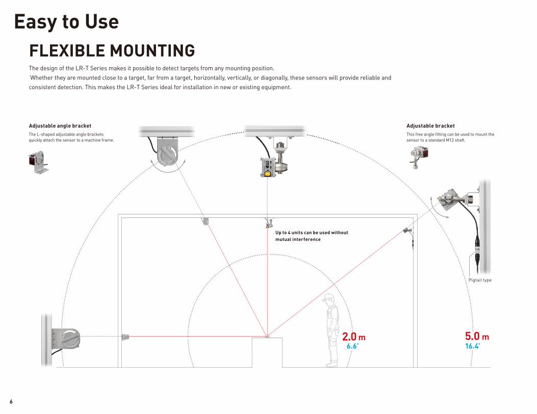
16.4’
This free angle fi tting can be used to mount the sensor to a standard M12 shaft.
Pigtail type
The L-shaped adjustable angle brackets quickly attach the sensor to a machine frame.
Adjustable angle bracket Adjustable bracket
Up to 4 units can be used without mutual interference
5.0 m2.0 m 6.6’
The design of the LR-T Series makes it possible to detect targets from any mounting position. Whether they are mounted close to a target, far from a target, horizontally, vertically, or diagonally, these sensors will provide reliable and consistent detection. This makes the LR-T Series ideal for installation in new or existing equipment.
FLEXIBLE MOUNTING
Easy to Use
6
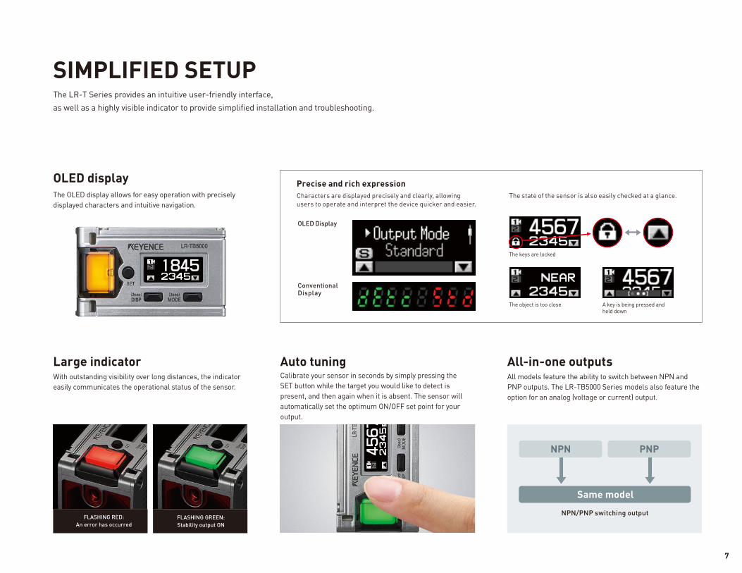
Characters are displayed precisely and clearly, allowing users to operate and interpret the device quicker and easier.
OLED Display
FLASHING RED: An error has occurred
FLASHING GREEN:Stability output ON
PNPNPN
Same model
NPN/PNP switching output
With outstanding visibility over long distances, the indicator easily communicates the operational status of the sensor.
Large indicatorCalibrate your sensor in seconds by simply pressing the SET button while the target you would like to detect is present, and then again when it is absent. The sensor will automatically set the optimum ON/OFF set point for your output.
Auto tuningAll models feature the ability to switch between NPN and PNP outputs. The LR-TB5000 Series models also feature the option for an analog (voltage or current) output.
All-in-one outputs
The OLED display allows for easy operation with precisely displayed characters and intuitive navigation.
OLED display
The object is too close
The keys are locked
A key is being pressed and held down
Conventional Display
The state of the sensor is also easily checked at a glance.
Precise and rich expression
The LR-T Series provides an intuitive user-friendly interface, as well as a highly visible indicator to provide simplifi ed installation and troubleshooting.
SIMPLIFIED SETUP
7
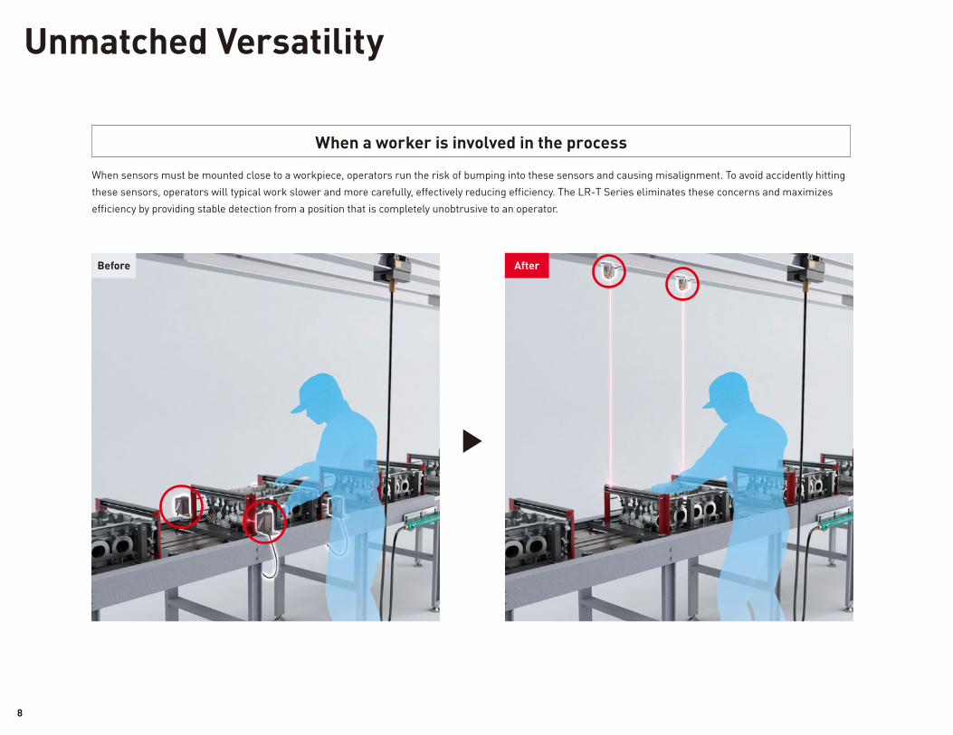
Unmatched Versatility
When sensors must be mounted close to a workpiece, operators run the risk of bumping into these sensors and causing misalignment. To avoid accidently hitting these sensors, operators will typical work slower and more carefully, effectively reducing effi ciency. The LR-T Series eliminates these concerns and maximizes effi ciency by providing stable detection from a position that is completely unobtrusive to an operator.
When a worker is involved in the process
AfterBefore
8
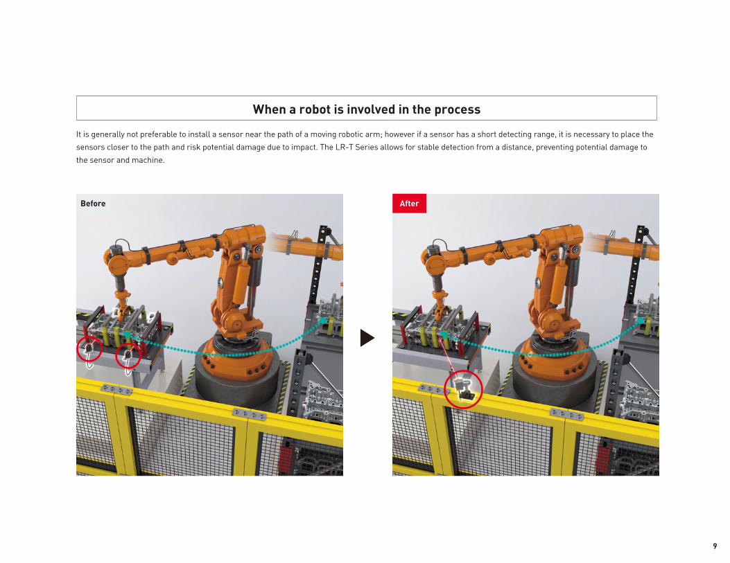
AfterBefore
It is generally not preferable to install a sensor near the path of a moving robotic arm; however if a sensor has a short detecting range, it is necessary to place the sensors closer to the path and risk potential damage due to impact. The LR-T Series allows for stable detection from a distance, preventing potential damage to the sensor and machine.
When a robot is involved in the process
9
General conveyance systems
Machining centers
Web tension controls
Welding cells
Transfer presses
Hopper level detection
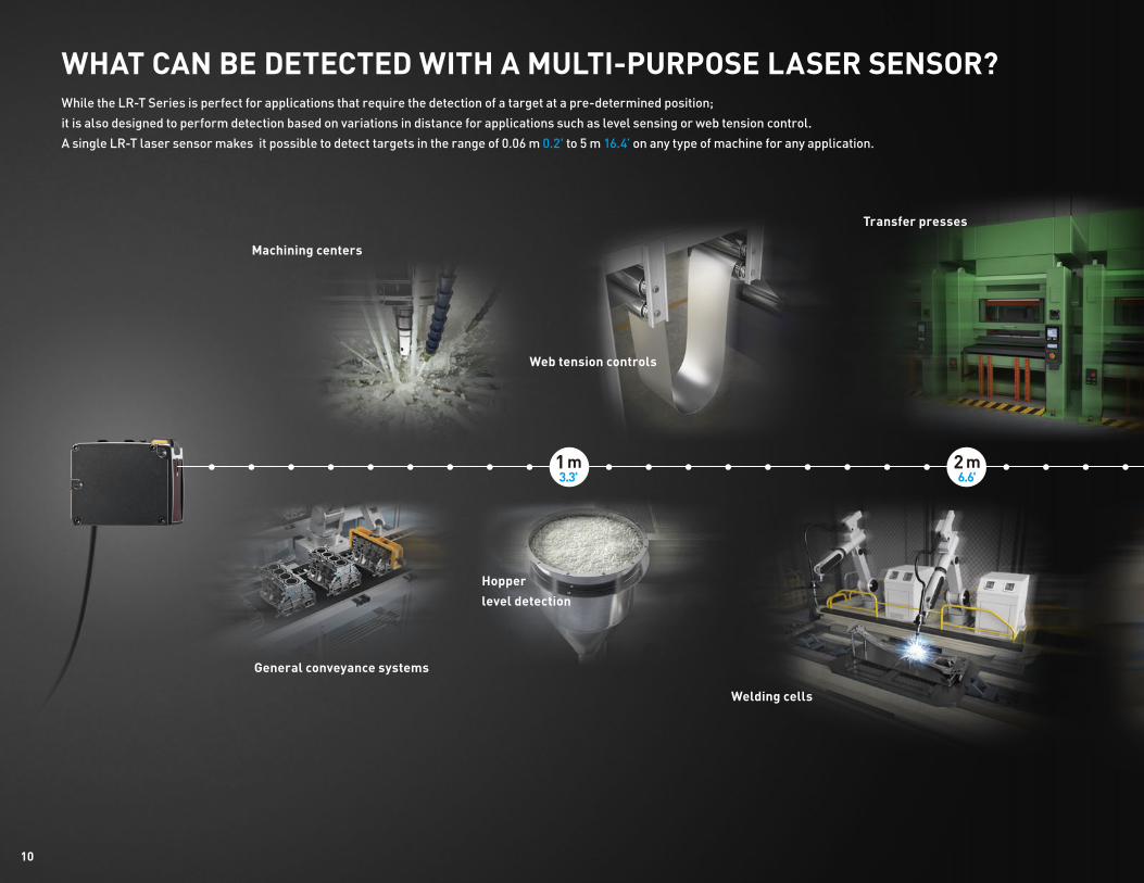
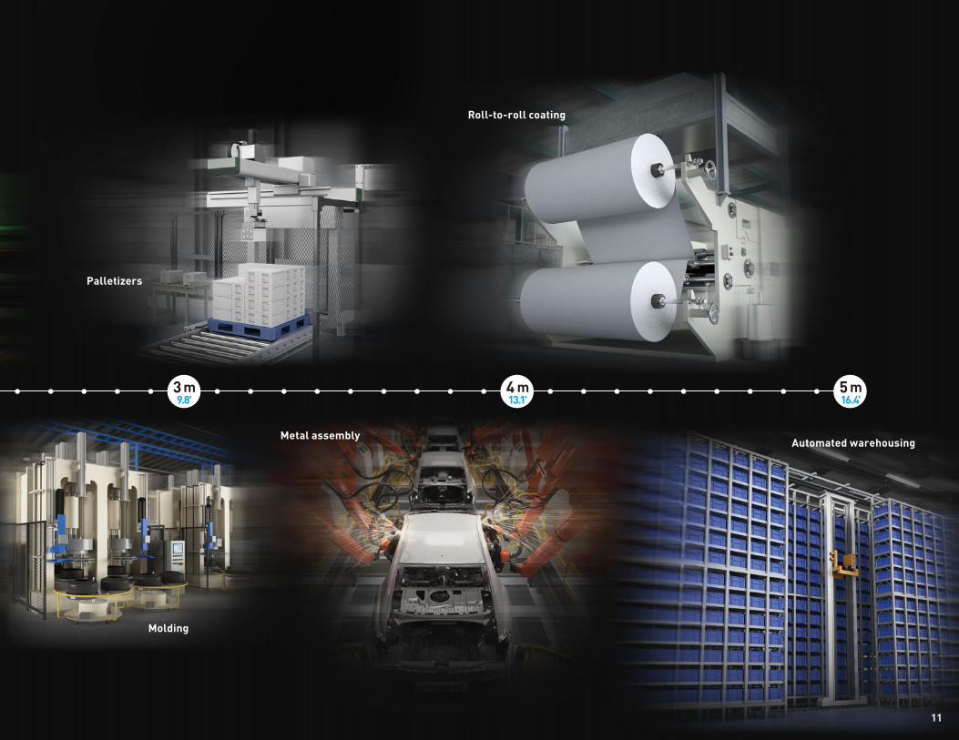
WHAT CAN BE DETECTED WITH A MULTI-PURPOSE LASER SENSOR?While the LR-T Series is perfect for applications that require the detection of a target at a pre-determined position; it is also designed to perform detection based on variations in distance for applications such as level sensing or web tension control.A single LR-T laser sensor makes it possible to detect targets in the range of 0.06 m 0.2' to 5 m 16.4’ on any type of machine for any application.
1 m3.3'
2 m6.6'
10
Molding
Metal assemblyAutomated warehousing
Palletizers
Roll-to-roll coating
3 m9.8'
4 m13.1'
5 m16.4'
11
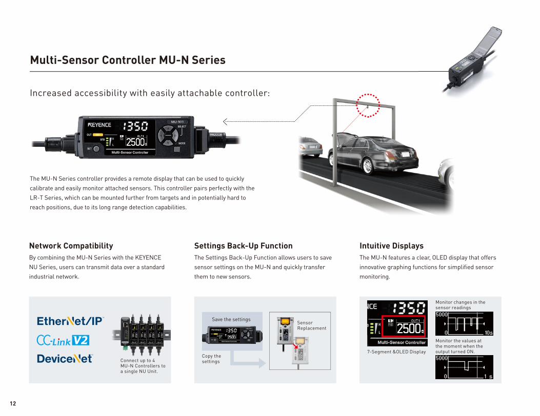
Multi-Sensor Controller MU-N Series
The MU-N Series controller provides a remote display that can be used to quickly calibrate and easily monitor attached sensors. This controller pairs perfectly with the LR-T Series, which can be mounted further from targets and in potentially hard to reach positions, due to its long range detection capabilities.
Increased accessibility with easily attachable controller:
Network Compatibility Settings Back-Up Function Intuitive DisplaysBy combining the MU-N Series with the KEYENCE NU Series, users can transmit data over a standard industrial network.
The Settings Back-Up Function allows users to save sensor settings on the MU-N and quickly transfer them to new sensors.
The MU-N features a clear, OLED display that offers innovative graphing functions for simplifi ed sensor monitoring.
Monitor the values at the moment when the output turned ON.
Monitor changes in the sensor readings
Connect up to 4 MU-N Controllers to a single NU Unit.
Save the settingsSensor Replacement
Copy the settings
7-Segment &OLED Display
12
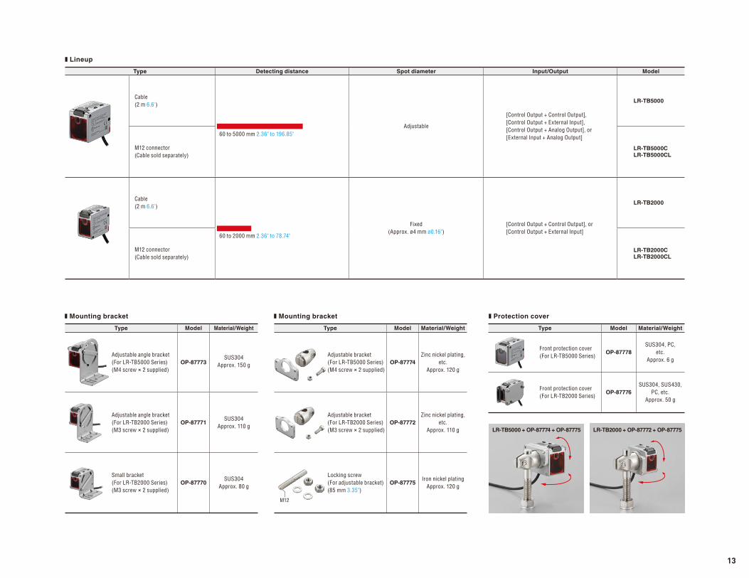
Type Detecting distance Spot diameter Input/Output Model
Cable(2 m 6.6')
60 to 5000 mm 2.36" to 196.85"Adjustable
[Control Output + Control Output],[Control Output + External Input],[Control Output + Analog Output], or [External Input + Analog Output]
LR-TB5000
M12 connector(Cable sold separately)
LR-TB5000CLR-TB5000CL
Cable(2 m 6.6')
60 to 2000 mm 2.36" to 78.74"
Fixed(Approx. ø4 mm ø0.16")
[Control Output + Control Output], or[Control Output + External Input]
LR-TB2000
M12 connector(Cable sold separately)
LR-TB2000CLR-TB2000CL
Type Model Material/Weight
Adjustable angle bracket(For LR-TB5000 Series)(M4 screw × 2 supplied)
OP-87773SUS304
Approx. 150 g
Adjustable angle bracket(For LR-TB2000 Series)(M3 screw × 2 supplied)
OP-87771SUS304
Approx. 110 g
Small bracket(For LR-TB2000 Series)(M3 screw × 2 supplied)
OP-87770SUS304
Approx. 80 g
Type Model Material/Weight
Front protection cover(For LR-TB5000 Series)
OP-87778
SUS304, PC, etc.
Approx. 6 g
Front protection cover(For LR-TB2000 Series)
OP-87776
SUS304, SUS430, PC, etc.
Approx. 50 g
Type Model Material/Weight
Adjustable bracket (For LR-TB5000 Series)(M4 screw × 2 supplied)
OP-87774
Zinc nickel plating, etc.
Approx. 120 g
Adjustable bracket (For LR-TB2000 Series)(M3 screw × 2 supplied)
OP-87772
Zinc nickel plating, etc.
Approx. 110 g
Locking screw (For adjustable bracket)(85 mm 3.35")
OP-87775Iron nickel plating
Approx. 120 g
M12
❚ Lineup
❚ Mounting bracket ❚ Protection cover❚ Mounting bracket
LR-TB5000 + OP-87774 + OP-87775 LR-TB2000 + OP-87772 + OP-87775
13
0 V
20 to 30 VDC➀Brown
➃Black
➁White
➂Blue
Mai
n ci
rcui
t Load
Load
Over
curr
ent p
rote
ctio
n ci
rcui
t
0 V
20 to 30 VDC➀Brown
➃Black
➁White
➂Blue
Mai
n ci
rcui
t
Load
Load
Over
curr
ent p
rote
ctio
n ci
rcui
t
1
2
34
0 V
Analog current/voltage output circuit
Analog input device
20 to 30 VDC➀Brown
➁White
➂Blue
Mai
n ci
rcui
t
0 V
20 to 30 VDC➀Brown
➃Black
➂BluePLC, etc.
Mai
n ci
rcui
t
0 V
20 to 30 VDC➀Brown
➃Black
PLC, etc.
➂Blue
Mai
n ci
rcui
t
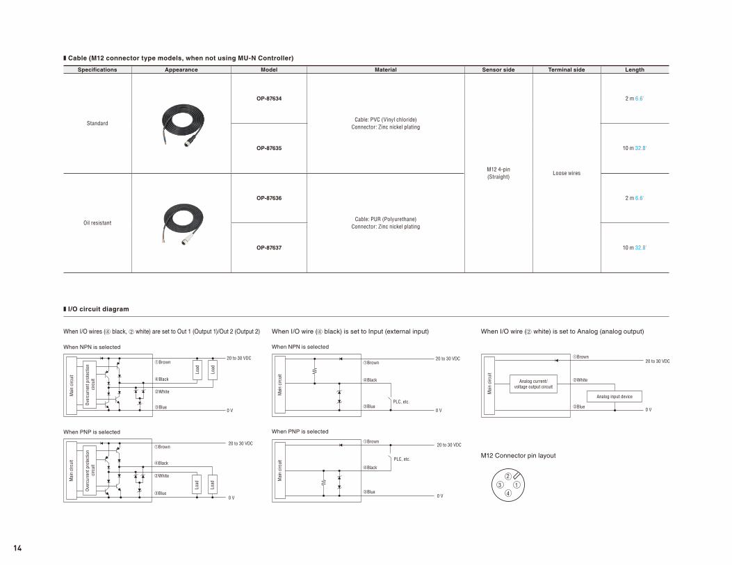
❚ Cable (M12 connector type models, when not using MU-N Controller)
❚ I/O circuit diagram
When NPN is selectedWhen NPN is selected
When I/O wires (➃ black, ➁ white) are set to Out 1 (Output 1)/Out 2 (Output 2) When I/O wire (➃ black) is set to Input (external input) When I/O wire (➁ white) is set to Analog (analog output)
M12 Connector pin layout
When PNP is selected When PNP is selected
Specifications Appearance Model Material Sensor side Terminal side Length
Standard
OP-87634
Cable: PVC (Vinyl chloride)Connector: Zinc nickel plating
M12 4-pin(Straight)
Loose wires
2 m 6.6'
OP-87635 10 m 32.8'
Oil resistant
OP-87636
Cable: PUR (Polyurethane)Connector: Zinc nickel plating
2 m 6.6'
OP-87637 10 m 32.8'
14
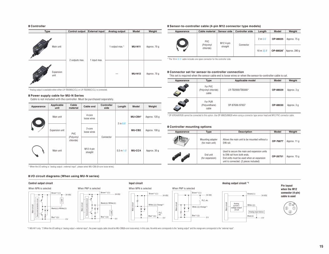
❚ Controller
❚ I/O circuit diagrams (When using MU-N series)
*1 MU-N11 only *2 When the I/O setting is “analog output + external input”, the power supply cable should be MU-CB8(8-core loose wires). In this case, the white wire corresponds to the “analog output” and the orange wire corresponds to the “external input”.
Type Control output External input Analog output Model Weight
Main unit
2 outputs max. 1 input max.
1 output max.* MU-N11 Approx. 70 g
Expansion unit
— MU-N12 Approx. 70 g
* Analog output is available when either LR-TB5000(C/CL) or LR-TB2000(C/CL) is connected.
AppearanceApplicable
unitCable
materialCable end
Controller side
Length Model Weight
Main unit
PVC (Polyvinyl chloride)
4-core loose wires
Connector
2 m 6.6'
MU-CB4* Approx. 120 g
Expansion unit2-core
loose wiresMU-CB2 Approx. 100 g
Main unitM12 4-pin
straight0.3 m 1.0' MU-CC4 Approx. 30 g
* When the I/O setting is “analog output + external input”, please select MU-CB8 (8-core loose wires).
❚ Power supply cable for MU-N Series Cable is not included with the controller. Must be purchased separately.
Appearance Cable material Sensor side Controller side Length Model Weight
PVC (Polyvinyl chloride)
M12 4-pinstraight
Connector
2 m 6.6' OP-88025 Approx. 75 g
10 m 32.8' OP-88026* Approx. 280 g
* The 10 m 32.8' cable includes one spare connector for the controller side.
❚ Sensor-to-controller cable (4-pin M12 connector type models)
Appearance Type Applicable model Model Weight
For PVC (Polyvinyl chloride)
cableLR-TB2000/TB5000* OP-88029 Approx. 3 g
For PUR (Polyurethane)
cableOP-87636/87637 OP-88030 Approx. 3 g
* OP-87634/87635 cannot be connected to this option. Use OP-88025/88026 when using a connector type sensor head and M12 PVC connector cable.
❚ Connector set for sensor-to-controller connection This set is required when the sensor cable end is loose wires or when the sensor-to-controller cable is cut.
Appearance Type Description Model Weight
Mounting adapter (for main unit)
Allows the main unit to be mounted without a DIN rail.
OP-76877 Approx. 11 g
End unit (for expansion)
Used to secure the main and expansion units to DIN rail from both ends. End units must be used when an expansion unit is connected. (2 pieces included)
OP-26751 Approx. 15 g
❚ Controller mounting options
0 V
24 VDCBrown( )
White ( )
Blue( )
Analog current /
voltage output circuit
Analog input device
Mai
n ci
rcui
t
0 V
24 VDC
White ( ) /Orange*2
PLC, etc.
Brown*1( )
Blue*1( )
Mai
n ci
rcui
t
0 V
24 VDCBrown*1( )
White ( ) /Orange*2
Blue*1( )
PLC, etc.
Mai
n ci
rcui
t
0 V
24 VDCBrown*1( )
Black( ) /White( )
Blue*1( )
Mai
n ci
rcui
t
Load
Over
curre
nt p
rotec
tion
circu
it
0 V
24 VDCBrown*1( )
Black( ) /White( )
Blue*1( )
Mai
n ci
rcui
t
Over
curre
nt pr
otec
tion c
ircuit
Load
1
2
34
Control output circuit
When NPN is selected When NPN is selectedWhen PNP is selected When PNP is selected
Input circuit Analog output circuit *1Pin layout when the M12 connector (4-pin) cable is used
15
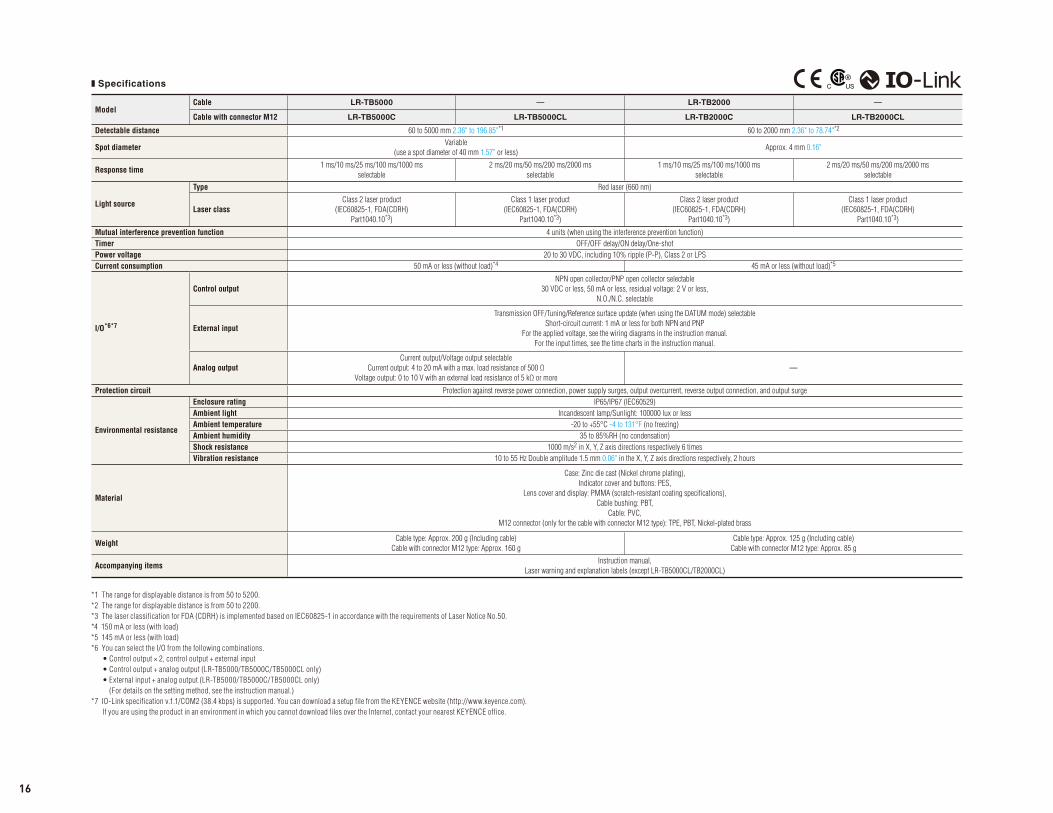
❚ Specifications
ModelCable LR-TB5000 — LR-TB2000 —
Cable with connector M12 LR-TB5000C LR-TB5000CL LR-TB2000C LR-TB2000CL
Detectable distance 60 to 5000 mm 2.36" to 196.85"*1 60 to 2000 mm 2.36" to 78.74"*2
Spot diameterVariable
(use a spot diameter of 40 mm 1.57" or less)Approx. 4 mm 0.16"
Response time1 ms/10 ms/25 ms/100 ms/1000 ms
selectable
2 ms/20 ms/50 ms/200 ms/2000 ms
selectable
1 ms/10 ms/25 ms/100 ms/1000 ms
selectable
2 ms/20 ms/50 ms/200 ms/2000 ms
selectable
Light source
Type Red laser (660 nm)
Laser classClass 2 laser product
(IEC60825-1, FDA(CDRH)
Part1040.10*3)
Class 1 laser product
(IEC60825-1, FDA(CDRH)
Part1040.10*3)
Class 2 laser product
(IEC60825-1, FDA(CDRH)
Part1040.10*3)
Class 1 laser product
(IEC60825-1, FDA(CDRH)
Part1040.10*3)
Mutual interference prevention function 4 units (when using the interference prevention function)
Timer OFF/OFF delay/ON delay/One-shot
Power voltage 20 to 30 VDC, including 10% ripple (P-P), Class 2 or LPS
Current consumption 50 mA or less (without load)*4 45 mA or less (without load)*5
I/O*6*7
Control outputNPN open collector/PNP open collector selectable
30 VDC or less, 50 mA or less, residual voltage: 2 V or less,
N.O./N.C. selectable
External input
Transmission OFF/Tuning/Reference surface update (when using the DATUM mode) selectable
Short-circuit current: 1 mA or less for both NPN and PNP
For the applied voltage, see the wiring diagrams in the instruction manual.
For the input times, see the time charts in the instruction manual.
Analog outputCurrent output/Voltage output selectable
Current output: 4 to 20 mA with a max. load resistance of 500 Ω
Voltage output: 0 to 10 V with an external load resistance of 5 kΩ or more
—
Protection circuit Protection against reverse power connection, power supply surges, output overcurrent, reverse output connection, and output surge
Environmental resistance
Enclosure rating IP65/IP67 (IEC60529)
Ambient light Incandescent lamp/Sunlight: 100000 lux or less
Ambient temperature -20 to +55°C -4 to 131°F (no freezing)
Ambient humidity 35 to 85%RH (no condensation)
Shock resistance 1000 m/s2 in X, Y, Z axis directions respectively 6 times
Vibration resistance 10 to 55 Hz Double amplitude 1.5 mm 0.06" in the X, Y, Z axis directions respectively, 2 hours
Material
Case: Zinc die cast (Nickel chrome plating),
Indicator cover and buttons: PES,
Lens cover and display: PMMA (scratch-resistant coating specifications),
Cable bushing: PBT,
Cable: PVC,
M12 connector (only for the cable with connector M12 type): TPE, PBT, Nickel-plated brass
WeightCable type: Approx. 200 g (Including cable)
Cable with connector M12 type: Approx. 160 g
Cable type: Approx. 125 g (Including cable)
Cable with connector M12 type: Approx. 85 g
Accompanying itemsInstruction manual,
Laser warning and explanation labels (except LR-TB5000CL/TB2000CL)
*1 The range for displayable distance is from 50 to 5200.
*2 The range for displayable distance is from 50 to 2200.
*3 The laser classification for FDA (CDRH) is implemented based on IEC60825-1 in accordance with the requirements of Laser Notice No.50.
*4 150 mA or less (with load)
*5 145 mA or less (with load)
*6 You can select the I/O from the following combinations.
• Control output × 2, control output + external input
• Control output + analog output (LR-TB5000/TB5000C/TB5000CL only)
• External input + analog output (LR-TB5000/TB5000C/TB5000CL only)
(For details on the setting method, see the instruction manual.)
*7 IO-Link specification v.1.1/COM2 (38.4 kbps) is supported. You can download a setup file from the KEYENCE website (http://www.keyence.com).
If you are using the product in an environment in which you cannot download files over the Internet, contact your nearest KEYENCE office.
16
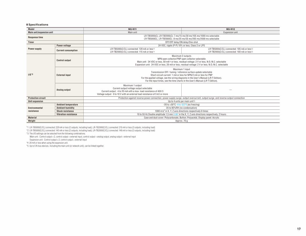
❚ Specifications
*1 LR-TB5000(C/CL) connected: 220 mA or less (2 outputs, including load), LR-TB2000(C/CL) connected: 215 mA or less (2 outputs, including load)
*2 LR-TB5000(C/CL) connected: 145 mA or less (2 outputs, including load), LR-TB2000(C/CL) connected: 140 mA or less (2 outputs, including load)
*3 The I/O settings can be selected from the following combinations.
Main unit: Control output × 2, control output + external input, control output + analog output, analog output + external input
Expansion unit: Control output × 2, control output + external input
*4 20 mA or less when using the expansion unit.
*5 Up to 5 N-bus devices, including the main unit (or network unit), can be linked together.
Model MU-N11 MU-N12
Main unit/expansion unit Main unit Expansion unit
Response timeLR-TB5000(C), LR-TB2000(C): 7 ms/15 ms/30 ms/105 ms/1000 ms selectableLR-TB5000CL, LR-TB2000CL: 8 ms/25 ms/55 ms/205 ms/2000 ms selectable
Timer OFF/OFF delay/ON delay/One-shot
Power supplyPower voltage 24 VDC, ripple (P-P) 10% or less, Class 2 or LPS
Current consumptionLR-TB5000(C/CL) connected: 120 mA or less*1
LR-TB2000(C/CL) connected: 115 mA or less*1
LR-TB5000(C/CL) connected: 105 mA or less*2
LR-TB2000(C/CL) connected: 100 mA or less*2
I/O*3
Control output
Maximum 2 outputsNPN open collector/PNP open collector selectable
Main unit: 24 VDC or less, 50 mA*4 or less, residual voltage: 2 V or less, N.O./N.C. selectableExpansion unit: 24 VDC or less, 20 mA or less, residual voltage: 2 V or less, N.O./N.C. selectable
External input
Maximum 1 inputTransmission OFF / tuning / reference surface update selectableShort-circuit current: 1 mA or less for NPN/2 mA or less for PNP
For the applied voltage, see the wiring diagrams in the User’s Manual (LR-T Edition).For the input times, see the time charts in the User’s Manual (LR-T Edition).
Analog output
Maximum 1 outputCurrent output/voltage output selectable
Current output: 4 to 20 mA with a max. load resistance of 450 ΩVoltage output: 0 to 10 V with an external load resistance of 5 kΩ or more
—
Protection circuit Protection against reverse power connection, power supply surge, output overcurrent, output surge, and reverse output connectionUnit expansion Up to 4 units per main unit*5
Environmentalresistance
Ambient temperature -20 to +50°C -4 to 122ºF (no freezing)Ambient humidity 35 to 85%RH (no condensation)Shock resistance 1000 m/s2 in X, Y, Z axis directions respectively 6 timesVibration resistance 10 to 55 Hz Double amplitude 1.5 mm 0.06" in the X, Y, Z axis directions respectively, 2 hours
Material Case and dust cover: Polycarbonate, Button: Polyacetal, Display panel: AcrylicWeight Approx. 70 g
17
18
7
6
5 3NARROWWIDE
2
4
X0
18
7
6
5 3NARROWWIDE
2
4
X0
Diameter of approx. 40 mm 1.57"
18
7
6
5 3NARROWWIDE
2
4Diameter of approx. 6 mm 0.24"
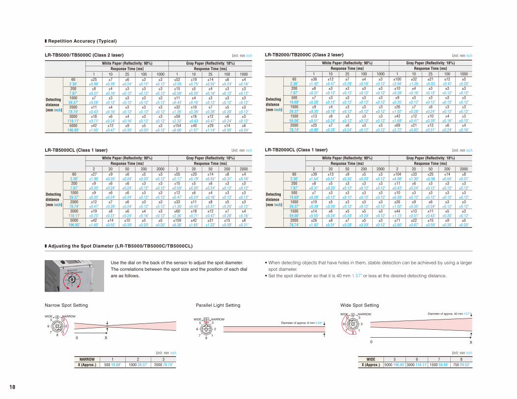
NARROW 1 2 3X (Approx.) 500 19.69" 1000 39.37" 2000 78.74"
WIDE 5 6 7 8X (Approx.) 5000 196.85" 3000 118.11" 1500 59.06" 750 29.53"
❚ Repetition Accuracy (Typical)
❚ Adjusting the Spot Diameter (LR-TB5000/TB5000C/TB5000CL)
LR-TB5000/ TB5000C (Class 2 laser)
LR-TB5000CL (Class 1 laser)
LR-TB2000/TB2000C (Class 2 laser)
LR-TB2000CL (Class 1 laser)
White Paper (Refl ectivity: 90%) Gray Paper (Refl ectivity: 18%)Response Time [ms] Response Time [ms]
1 10 25 100 1000 1 10 25 100 1000
Detecting distance[mm inch]
602.36"
±25±0.98"
±7±0.28"
±6±0.24"
±3±0.12"
±3±0.12"
±52±2.05
±19±0.75"
±14±0.55"
±6±0.24"
±4±0.16"
2007.87"
±8±0.31"
±4±0.16"
±3±0.12"
±3±0.12"
±3±0.12"
±15±0.59"
±5±0.20"
±4±0.16"
±3±0.12"
±3±0.12"
100039.37"
±7±0.28"
±3±0.12"
±3±0.12"
±3±0.12"
±3±0.12"
±11±0.43"
±4±0.16"
±3±0.12"
±3±0.12"
±3±0.12"
200078.74"
±11±0.43"
±4±0.16"
±3±0.12"
±3±0.12"
±3±0.12"
±32±1.26"
±10±0.39"
±7±0.28"
±5±0.20"
±3±0.12"
3000118.11"
±18±0.71"
±6±0.24"
±4±0.16"
±3±0.12"
±3±0.12"
±59±2.32"
±16±0.63
±12±0.47"
±6±0.24"
±3±0.12"
5000196.85"
±42±1.65"
±12±0.47"
±9±0.35"
±5±0.20"
±3±0.12"
±154±6.06"
±40±1.57"
±29±1.14"
±14±0.55"
±6±0.24"
White Paper (Refl ectivity: 90%) Gray Paper (Refl ectivity: 18%)Response Time [ms] Response Time [ms]
2 20 50 200 2000 2 20 50 200 2000
Detecting distance[mm inch]
602.36"
±27±1.06"
±9±0.35"
±6±0.24"
±5±0.20"
±3±0.12"
±55±2.17"
±20±0.79"
±14±0.55"
±8±0.31"
±4±0.16"
2007.87"
±9±0.35"
±6±0.24"
±6±0.24"
±3±0.12"
±3±0.12"
±15±0.59"
±5±0.20"
±6±0.24"
±3±0.12"
±3±0.12"
100039.37"
±9±0.35"
±6±0.24"
±6±0.24"
±3±0.12"
±3±0.12"
±12±0.47"
±6±0.24"
±4±0.16"
±3±0.12"
±3±0.12"
200078.74"
±12±0.47"
±7±0.28"
±6±0.24"
±3±0.12"
±3±0.12"
±33±1.30"
±11±0.43"
±8±0.31"
±5±0.20"
±3±0.12"
3000118.11"
±19±0.75"
±8±0.31"
±6±0.24"
±4±0.16"
±3±0.12"
±60±2.36"
±18±0.71"
±12±0.47"
±7±0.28"
±4±0.16"
5000196.85"
±42±1.65"
±14±0.55"
±10±0.39"
±5±0.20"
±5±0.20"
±159±6.26"
±42±1.65"
±31±1.22"
±15±0.59"
±8±0.31"
White Paper (Refl ectivity: 90%) Gray Paper (Refl ectivity: 18%)Response Time [ms] Response Time [ms]
1 10 25 100 1000 1 10 25 100 1000
Detecting distance[mm inch]
602.36"
±36±1.42"
±12±0.47"
±7±0.28"
±4±0.16"
±3±0.12"
±100±3.94"
±32±1.26
±21±0.83
±12±0.47
±5±0.20"
2007.87"
±8±0.31"
±3±0.12"
±3±0.12"
±3±0.12"
±3±0.12"
±10±0.39"
±4±0.16"
±3±0.12"
±3±0.12"
±3±0.12"
50019.69"
±7±0.28"
±3±0.12"
±3±0.12"
±3±0.12"
±3±0.12"
±9±0.35"
±3±0.12"
±3±0.12"
±3±0.12"
±3±0.12"
100039.37"
±9±0.35"
±4±0.16"
±3±0.12"
±3±0.12"
±3±0.12"
±26±1.02"
±7±0.28"
±6±0.24"
±3±0.12"
±3±0.12"
150059.06"
±13±0.51"
±6±0.24"
±3±0.12"
±3±0.12"
±3±0.12"
±43±1.69"
±12±0.47"
±10±0.39"
±4±0.16"
±3±0.12"
200078.74"
±25±0.98"
±7±0.28"
±6±0.24"
±3±0.12"
±3±0.12"
±69±2.72"
±21±0.83"
±13±0.51"
±6±0.24"
±4±0.16"
White Paper (Refl ectivity: 90%) Gray Paper (Refl ectivity: 18%)Response Time [ms] Response Time [ms]
2 20 50 200 2000 2 20 50 200 2000
Detecting distance[mm inch]
602.36"
±39±1.54"
±13±0.51"
±9±0.35"
±5±0.20"
±3±0.12"
±104±4.09"
±33±1.30"
±25±0.98
±14±0.55"
±8±0.31"
2007.87"
±8±0.31"
±5±0.20"
±3±0.12"
±3±0.12"
±3±0.12"
±11±0.43"
±6±0.24"
±3±0.12"
±3±0.12"
±3±0.12"
50019.69"
±7±0.28"
±3±0.12"
±3±0.12"
±3±0.12"
±3±0.12"
±10±0.39"
±3±0.12"
±3±0.12"
±3±0.12"
±3±0.12"
100039.37"
±10±0.39"
±5±0.20"
±3±0.12"
±3±0.12"
±3±0.12"
±26±1.02"
±9±0.35"
±6±0.24"
±3±0.12"
±3±0.12"
150059.06"
±14±0.55"
±6±0.24"
±5±0.20"
±5±0.20"
±3±0.12"
±44±1.73"
±13±0.51"
±11±0.43"
±5±0.20"
±3±0.12"
200078.74"
±26±1.02"
±8±0.31"
±7±0.28"
±5±0.20"
±3±0.12"
±71±2.80"
±22±0.87"
±15±0.59"
±9±0.35"
±5±0.20"
Use the dial on the back of the sensor to adjust the spot diameter.
The correlations between the spot size and the position of each dial
are as follows.
Narrow Spot Setting Wide Spot SettingParallel Light Setting
• When detecting objects that have holes in them, stable detection can be achieved by using a larger
spot diameter.
• Set the spot diameter so that it is 40 mm 1.57" or less at the desired detecting distance.
Unit: mm inchUnit: mm inch
Unit: mm inch
Unit: mm inchUnit: mm inch
Unit: mm inch
18
16.90.67"
28.41.12"
0.57"14.5
150.59"
0.27"6.8
26.6 1.05"
1.57"39.9
18 0.71"
51.4 2.02"
0.22"5.5 1.67"
0.05"
42.4 11.3 0.44"
1.11"28.3
0.65"16.5
110.43"
80.31"
20.30.80"
35.91.41"
40.91.61"
1.50.06"
1.5 0.06"1.2
43.21.70"
90°
30.6 1.20"
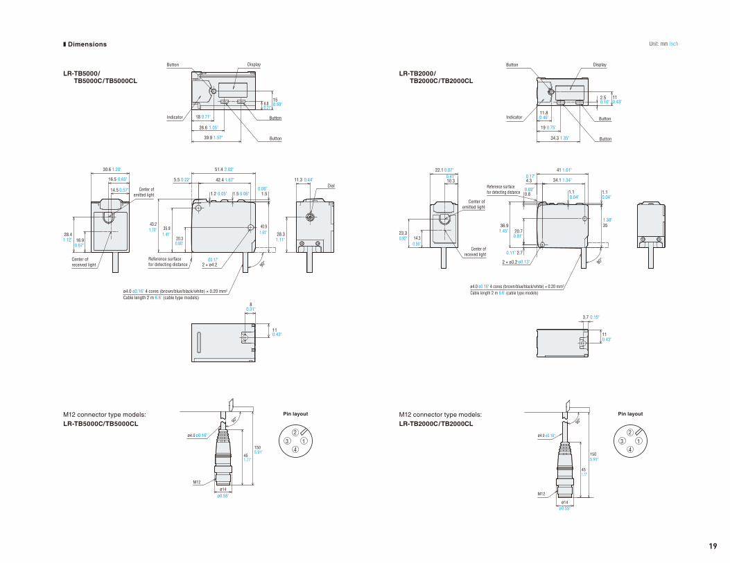
Indicator
Center of received light
Center of emitted light
Reference surface for detecting distance
ø4.0 ø0.16" 4 cores (brown/blue/black/white) × 0.20 mm2
Cable length 2 m 6.6' (cable type models)
Button
Dial
Display
Button
Button
2 × ø4.2Ø0.17"
1505.91"
451.77"
90°
ø14
ø0.55"
ø0.16"ø4.0
M12
1
2
34
1505.91"
451.77"
90°
M12
ø14ø0.55"
ø4.0 ø0.16"
36.9
2.70.11"
20.70.81"
1.45"
34.1 1.34"
41 1.61"
1.10.04"0.04"
0.75"19
34.3 1.35"
0.46"11.8
2.50.10" 0.43"
11
22.1 0.87"
14.30.56"
0.92"23.3
10.30.41"
0.80.03"
90°
4.30.17"
351.38"
1.1
3.7 0.15"
110.43"
ø4.0 ø0.16" 4 cores (brown/blue/black/white) × 0.20 mm2
Cable length 2 m 6.6' (cable type models)
Reference surface for detecting distance
Center of emitted light
Center of received light
2 × ø3.2 ø0.13"
Button
Button
Indicator
Button Display
1
2
34
LR-TB5000/TB5000C/TB5000CL
LR-TB2000/TB2000C/TB2000CL
M12 connector type models:
LR-TB5000C/TB5000CL
M12 connector type models:
LR-TB2000C/TB2000CL
Pin layoutPin layout
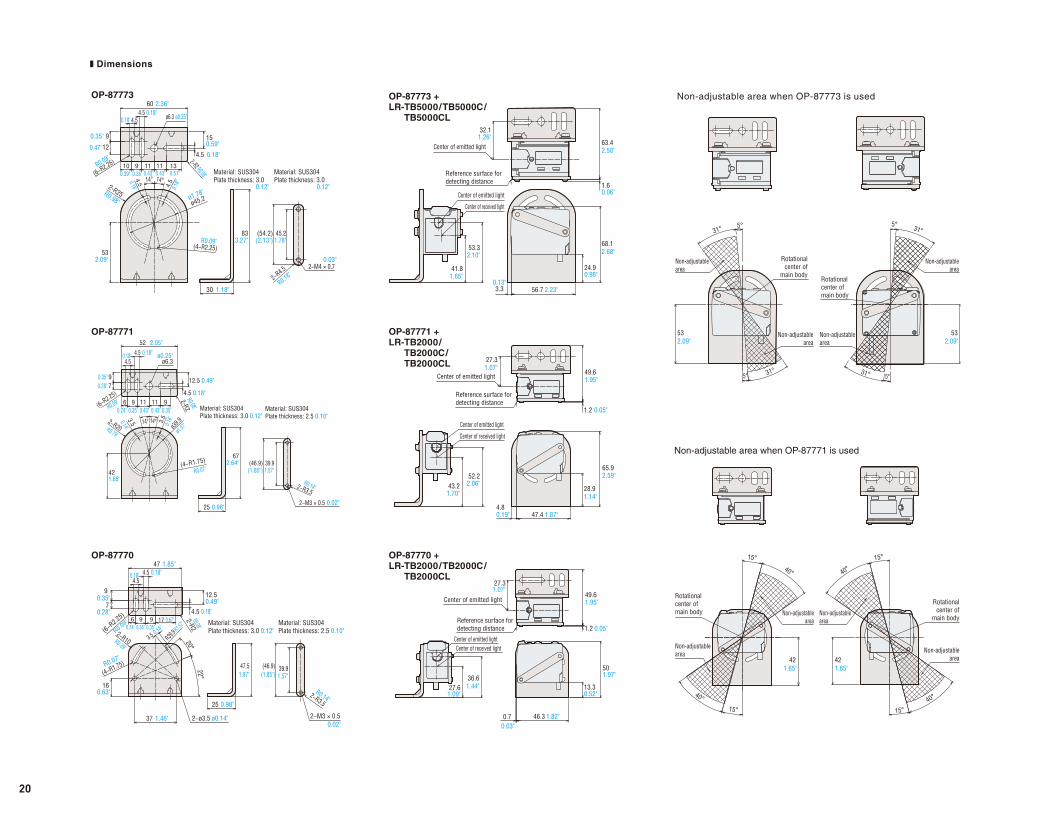
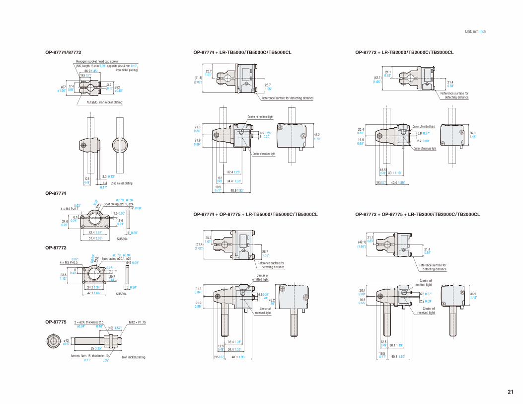
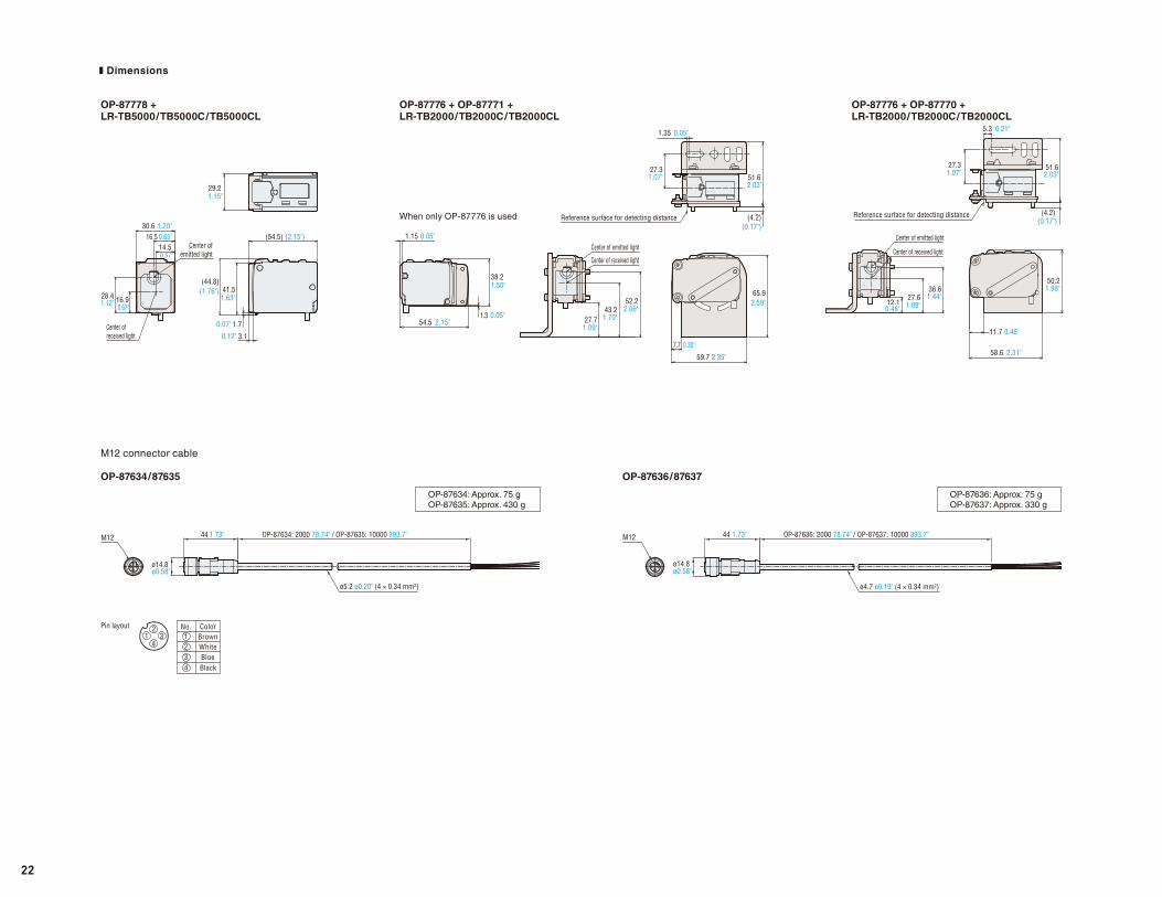
Unit: mm inch❚ Dimensions
19
47 1.85"
90.35"
0.28"7
60.24" 0.35" 0.35"
0.67"9 9 17
12.50.49"
4.5
4.54.5 0.18"
0.18"
0.18"
160.63"
R39.92−R10
22°
20°
37 1.46"
0.14"
R0.39"
R0.07"
R1.57"
R0.14"
3.5
(4−R1.75)
25 0.98"
ø0.14"
(6−R2.25)
47.51.87"
2-R2
39.91.57"
(46.9)(1.85")
2−R3.5
Material: SUS304Plate thickness: 3.0 0.12"
Material: SUS304Plate thickness: 2.5 0.10"
2−M3 × 0.52−ø3.5
R0.09"
R0.08"
0.02"
90.35"70.28"
0.49"
R0.08"
R0.07"
R0.14"
R0.09"
12.5
4.5 0.18"6 9
0.35"0.24" 0.35"0.43"0.43"11 11 9 2-R2(6−R2.25)
4.54.5 0.18"0.18"
52 2.05"
14°14° 3.5
0.14"0.14"R0.79" ø1.
57"2−R20 ø3
9.9
25 0.98"
672.64"
421.65"
(4−R1.75)
3.5
39.9(46.9)(1.85") 1.57"
2−R3.5
ø6.3ø0.25"
Material: SUS304Plate thickness: 3.0 0.12"
Material: SUS304Plate thickness: 2.5 0.10"
2−M3 × 0.5 0.02"
2−M4 × 0.7
90.35"
120.47"
4.54.5 0.18"
0.18"
60 2.36"
10 9 11 110.43" 0.51"0.43"0.35"0.39"
13
150.59"
4.5 0.18"
2−R2 R0.08"(6−R2.25)
2-R25 R0.98"
532.09"
(4−R2.25)
1.18"30
833.27"
ø45.2
14° 14°
4.5
0.18"
4.50.18"
45.21.78"
(54.2)(2.13")
2−R4.5
Material: SUS304Plate thickness: 3.0
Material: SUS304Plate thickness: 3.0
ø0.25"ø6.3
ø1.78"
R0.09"
R0.09"
0.12" 0.12"
R0.18"
0.03"
1.07"27.3
0.70.03"
46.3 1.82"
13.30.52"
501.97"
49.61.95"
36.61.44"
1.09"27.6
1.2 0.05"Reference surface for detecting distance
Center of emitted lightCenter of received light
Center of emitted light
41.81.65"
53.32.10"
32.11.26"
63.42.50"
1.60.06"
3.30.13"
56.7 2.23"
24.90.98"
68.12.68"
Reference surface for detecting distance
Center of emitted light
Center of emitted light
Center of received light
Reference surface for detecting distance
Center of emitted light
Center of emitted light
Center of received light
43.21.70"
52.22.06"
47.4 1.87"4.80.19"
28.91.14"
65.92.59"
27.31.07"
49.61.95"
1.2 0.05"
42 421.65"1.65"
Non-adjustable area
Non-adjustable area
Non-adjustable area
Non-adjustable area
Rotational center of main body
40°
15°
15°
40°
Rotational center of
main body
15°
40°
15°40°
Non-adjustable area
Non-adjustable area
Non-adjustable area
Non-adjustable area
532.09" 2.09"
53
Rotational center of
main body
5°31°
5° 31°
5° 31°
Rotational center of main body
31° 5°
OP-87773 OP-87773 + LR-TB5000/TB5000C/
TB5000CL
Non-adjustable area when OP-87773 is used
OP-87771 OP-87771 + LR-TB2000/
TB2000C/TB2000CL
OP-87770 OP-87770 + LR-TB2000/TB2000C/
TB2000CL
Non-adjustable area when OP-87771 is used
❚ Dimensions
20
21.40.84"
21.10.83"(42.1)
(1.66")
0.49"12.5
0.77"19.5
40.4 1.59"
36.91.45"
1.19"30.1
16.50.65"
20.40.80" 6.8 0.27"
2.2 0.09"
Reference surface for detecting distance
Center of emitted light
Center of received light
Center of emitted light
Center of received light
Reference surface for detecting distance
21.10.83"
(42.1)(1.66")
0.49"12.5
19.5 0.77"
30.1 1.19"
40.4 1.59"
36.91.45"
20.40.80"
16.50.65"
6.8 0.27"
2.2 0.09"
21.40.84"
25.71.01"
(51.4)(2.02")
26.71.05"
34.4 1.35"
32.4 1.28"
0.49"12.5
19.5 0.77" 48.9 1.93"
5 0.20"6.5 0.26"
43.21.70"
Reference surface for detecting distance
Center of emitted light
Center of received light
21.30.84"
21.90.86"
26.71.05"
25.71.01"
(51.4)(2.02")
43.21.70"
34.4 1.35"
19.50.77"
0.84"21.3
21.90.86"
0.49"12.5
48.9 1.93"
32.4 1.28"
6.5 0.26"5 0.20"
Reference surface for detecting distance
Center of emitted light
Center of received light
Spot facing ø20.1, ø24d=2
5 0.20"
R0.5
9"R1
5
34.1 1.34"
42.1 1.66"
110.43"28.8
1.13"
70.28"
20.70.81"
4 × M3 P=0.5
SUS304
ø0.79", ø0.94"
0.08"0.02"
5 0.20"
R15
42.4 1.67"
51.4 2.02"
6.10.24"24.6
0.97"
1.6
15.60.61"
0.06"4 × M4 P=0.7
SUS304
Spot facing ø20.1, ø24d=2 0.08"
R0.59
" ø0.79", ø0.94"
0.03"
Zinc nickel plating
Nut (M5, iron nickel plating)
Hexagon socket head cap screw(M5, length 15 mm 0.59", opposite side 4 mm 0.16", iron nickel plating)
ø22ø0.87"
36.9 1.45"19.5 0.77"
ø27ø1.06"
3.20.13"17.4
0.69"
0.49"12.5
3.3 0.13"
4.40.17"
Iron nickel platingAcross-flats 18, thickness 10
ø12ø0.47"
2 × ø24, thickness 2.5 M12 × P1.75
3.35"85
(40)(1.57")ø0.94"
0.71"
0.10"
0.39"
OP-87772 + LR-TB2000/TB2000C/TB2000CLOP-87774 + LR-TB5000/TB5000C/TB5000CLOP-87774/87772
OP-87774
OP-87772
OP-87772 + OP-87775 + LR-TB2000/TB2000C/TB2000CLOP-87774 + OP-87775 + LR-TB5000/TB5000C/TB5000CL
OP-87775
Unit: mm inch
21
Reference surface for detecting distance
Center of emitted light
Center of received light
12.10.48"
2.03"51.6
11.7 0.46"
50.21.98"
(0.17")(4.2)
27.31.07"
58.6 2.31"
27.61.09"
36.61.44"
5.3 0.21"
Reference surface for detecting distance
Center of emitted light
Center of received light
51.62.03"
(4.2)(0.17")
65.92.59"
7.7 0.30"
27.71.09"
27.31.07"
59.7 2.35"
43.21.70"
52.22.06"
1.35 0.05"
Center of received light
29.21.15"
1.70.07"
41.51.63"
3.10.12"
16.90.67"
28.41.12"
14.50.57"
0.65"16.530.6 1.20"
(54.5) (2.15")
(44.8)(1.76")
Center of emitted light
1.15 0.05"
1.3 0.05"
38.21.50"
54.5 2.15"
Pin layout No.
Black
WhiteBlue
ColorBrown1
234
34
12
ø14.8ø0.58"
44 OP-87634: 2000 78.74" / OP-87635: 10000 393.7"1.73"
ø5.2 ø0.20" (4 × 0.34 mm2)
M12 OP-87636: 2000 78.74" / OP-87637: 10000 393.7"44
ø14.8
1.73"
ø0.58"
ø4.7 ø0.19" (4 × 0.34 mm2)
M12
When only OP-87776 is used
OP-87634: Approx. 75 gOP-87635: Approx. 430 g
OP-87636: Approx. 75 gOP-87637: Approx. 330 g
OP-87778 +LR-TB5000/TB5000C/TB5000CL
OP-87776 + OP-87771 +LR-TB2000/TB2000C/TB2000CL
OP-87776 + OP-87770 +LR-TB2000/TB2000C/TB2000CL
M12 connector cable
OP-87634/87635 OP-87636/87637
❚ Dimensions
22
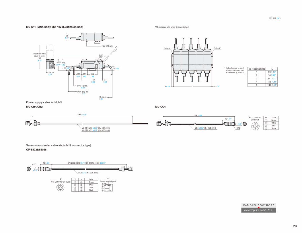
MU-N11 (Main unit)/ MU-N12 (Expansion unit)
Unit: mm inch
16 0.63"15.8 0.62"
15.5 min.0.61"
PUR: 28.2 min. 1.11"
PVC: 8.9 min.0.35"
19.50.77"
210.83"
Maximum when cover is open:
1084.25"
281.10"
78.43.09"
35.41.39"
23.70.93"
281.10"
36.91.45"
(41.9)(1.65")
MAX.135°
*MU-N12 only.
No. of expansion units12345
L28 1.10"56 2.20"84 3.31"112 4.41"140 5.51"
* End units must be used when an expansion unit is connected. (OP-26751)
End unit End unit *
L6 0.24" 6 0.24"
When expansion units are connected
45 1.77"
300 11.81"
ø14 ø0.55"
M12ø5.5 ø0.22" (4 × 0.35 mm2)
M12 Connector pin layout
No. ColorBrownWhiteBlueBlack
12
34MU-CB4:ø5.5 ø0.22" (4 × 0.35 mm2)
MU-CB2:ø5.5 ø0.22" (2 × 0.35 mm2)
2000 78.74"
MU-CB4/CB2 MU-CC4
Power supply cable for MU-N
XM12 Connector pin layout
12
34
YConnector pin layout
OP-88025:2000 78.74"/ OP-88026:10000 393.70"43 1.69"M12
ø4.0 0.16" (4 × 0.20 mm2)
ø14 ø0.55"
ColorBrownWhiteBlueBlack
YX
OP-88025/88026
Sensor-to-controller cable (4-pin M12 connector type)
CAD DATA DOWNLOAD
www.keyence.com/CADG
23
KA2-1017
www.keyence.com
LRT-KA-C2-US 1028-2 611C20 Copyright (c) 2016 KEYENCE CORPORATION. All rights reserved.
E-mail: [email protected] E-mail: [email protected]
E-mail: [email protected]
LR-TSERIES
A l l - P u r p o s e Laser Sensor
Related Documents


![Configuring VG224 Using AXL SQL Direct Queries [AXL THIN ... · VERSION: 03-01-2008 Configuring VG224 Using AXL SQL Direct Queries [AXL THIN API], Thick API [CM7]](https://static.cupdf.com/doc/110x72/5e48329b43b7a701dd344f4b/configuring-vg224-using-axl-sql-direct-queries-axl-thin-version-03-01-2008.jpg)