LPG Bulk Storage Equipment Kosan Crisplant is able to offer LPG bulk storage equipment and accessories that are needed for a safe and efficient operation of the installations and keep the safety on the operator’s side from downstream the bulk tank to the LPG cylinder filling carousel. Range of products: • Regenerative Turbine Pumps • Vane Positive Displacement Pumps • Side Channel Pumps • Bypass Valves • Compressors • Internal Valves • Globe and Angle valves • Hydrostatic Relief Valves • Sight Flow Indicators • Pull-Away Valves • Dry Seal Couplings • Excess Flow Valves - See chapter 2 • Emergency Shut-Off Valves The range Kosan Crisplant is offering is complete and matches several spec- ifications and different demands from various markets. Nevertheless, if you do not find what you need on the fol- lowing pages, we kindly ask you to contact us. We will do our best to pro- vide the best solution for your need. For proper support contact one of the KC offices closest to your location.

Welcome message from author
This document is posted to help you gain knowledge. Please leave a comment to let me know what you think about it! Share it to your friends and learn new things together.
Transcript

LPG Bulk Storage Equipment
Kosan Crisplant is able to offer
LPG bulk storage equipment
and accessories that are
needed for a safe and efficient
operation of the installations
and keep the safety on the
operator’s side from
downstream the bulk tank to
the LPG cylinder filling
carousel.
Range of products:
• Regenerative Turbine Pumps• Vane Positive Displacement Pumps• Side Channel Pumps• Bypass Valves• Compressors• Internal Valves• Globe and Angle valves• Hydrostatic Relief Valves• Sight Flow Indicators• Pull-Away Valves• Dry Seal Couplings• Excess Flow Valves - See chapter 2• Emergency Shut-Off Valves
The range Kosan Crisplant is offering is complete and matches several spec-ifications and different demands from various markets. Nevertheless, if you do not find what you need on the fol-lowing pages, we kindly ask you to contact us. We will do our best to pro-vide the best solution for your need.
For proper support contact one of the KC offices closest to your location.

38
C
Regenerative Turbine Pumps
Application
Regenerative turbine pumps are nor-mally a good choice for low-capacity and high-head pumping demands, where volatile liquid transfer is in-volved, as cylinder filling applications, vaporizers feed and autogas.
They are the best solution for low power applications where reliability is more important than energy efficiency, while for higher power applications (more than 10 HP), the improved ener-gy efficiency of vane pumps offsets their shorter service life.
Without the noise, vibration and pul-sations of the positive displacement gear and sliding vane pumps, the re-generative turbine pumps handles LPG for long lifetime periods.
The only moving part, the impeller, floats on the shaft with no rubbing, grinding or metal-to-metal contact.
MECHANICAL SPECIFICATIONS
INLET 1-1/4” NPT (Models F9, F10) 1-1/2” NPT (Models F12, F13, F14, F15) 11/2” ANSI 300 LB. (Models FF9-FF15)
OUTLET 1” NPT 1” ANSI 300 LB. (FF9-FF15)
ROTATION Clockwise only (From driven end)
MAX. RPM 3600 MAX. CASE TEST PRESSURE 172 Bar
MAX WORKING PRESSURE 27.6 Bar
MAX DIFFERENTIAL PRESSURE 10.3 BarHORSEPOWER RANGE 1/2 to 10
TEMPERATURE RANGE -32° to +107°C MAX. VISCOSITY 400 SSU
Mounting Alternatives
MATERIAL SPECIFICATIONS
Part Standard Optional
CASE/COVER Ductile Iron ASTM A-536 None
IMPELLER Bronze 303 Stainless Steel Ductile Iron
SHAFT Stressproof Steel 416 Stainless Steel
O-RINGS Buna N Teflon* Viton* Neoprene* Etylene-Propylene
SEAL SLEEVE Aluminum 416 Stainless Steel
SEAL SEAT Cast Iron 304 Stainless Steel Ni-Resist Ceramic Tungsten Carbide
SEAL HOUSING Steel, Cadmium Plated 416 Stainless Steel
* - Registered trad marks of do-port

39
C
Regenerative Turbine Pumps
Mounting Alternatives
Performance Curves
AUTOGAS SERIES SPECIFICATIONSSpecification All Coro-Flo® 075 and 150 ModelsInlet 1-1/2" - ANSI 300# R.F. Flange (DIN optional)
Outlet 1" - ANSI 300# R.F. Flange (DIN optional)RPM 3450 @ 60 Hz or 2.880 @ 50 HzMaximum Work Pressure 27.6 bar Maximum Diferential Pressure
Model 075 – 10,3 barModel 150 - 17.2 bar
Max/Min Temperature 107ºC/-32ºCImpeller Material Bronze (standard)O-ring material Buna-N (standard)Seal Materials Silicon carbide (standard)Maximum driver 15 KWType of electric motor* Rigid Base (Frame mount) and C-face (direct mount)
Performance Curves

40
C
Vane Positive Displacement Pumps
Application
The vane positive displacement pumps are the most popular pumps used on LPG high demand systems combining an interest solution of low cost and easy maintenance and they have a considerable efficiency.
The vanes are self adjusting in order to keep the distance tolerance with the rotor keeping the efficiency for long periods of time and they may be re-
Mounting Possibilities
MATERIAL SPECIFICATIONS FOR SERIES 521, 1021 AND F1021Part Model Standard Material Optional
Material Case, head, flange rotor, seat adapter plate
All Ductile iron ASTM A536 None
Cam, sideplate, bearing cap All Gray iron ASTM A48 Class 30 None Welding flange All Steel None Seal seat All Gray iron ASTM S48, Class 30 316 SS Seal metal parts All Steel None Shaft 521, 1021 “Stressproof” steel None Vanes All Plastic None Relief valve spring 521, 1021 Steel, cadmium plated None Relief valve 521, 1021 Steel None Bearing All Cylinder roller None O-rings All Buna-N PTFE, Viton®,
Neoprene®1 Retainer rings All Steel None
placed very easily.
Typical utilizations for vane positive displacement pumps are loading and unloading of bulk trucks and transport trucks, carrousel filling and cylinder fill-ing.
Some pumps have integrated relief valve for relieving the pressure from discharge to the suction side. For spe-cific truck (not stationary) vane positive displacement pumps, consult folder A.
MATERIAL SPECIFICATIONS FOR SERIES 51Part Model Standard Material Optional Material Case, head rotor All Ductile iron ASTM A536 None Sideplate All Gray iron ASTM A48, Class
30 None
Seal seat All Cast iron Ni-Resist cast iron, displacement type ceramic, and tungsten carbide
Seal rotor All Carbon None Seal metal parts All Steel None Vanes All Carbon None Relief valve springs All Steel, cadmium plated None Relief valve All Steel None Shaft All 8620 steel None Mounting bracket C51 Gray iron ASTM A48, Class
30 None
Base F51 Steel None O-rings All Buna-N PTFE, Viton®, Neoprene®1 Relief valve adjusting stem seal
All Buna-N None
Retainer rings All Steel None Bearings All Cylindrical roller None
Part Standard Material Optional Material
Case, head, rotor, relief-valve cap, bearing cap
Ductile iron ASTM A536
None
Cam Gray iron ASTM A48 Class 50
None
Sideplate Gray iron ASTM A48 Class 30
None
Welding flange Steel NoneSeal seat Gray iron 316 SS Seal metal parts Steel None Shaft 8620 steel None Vanes and vane drivers
Advanced polymers None
Relief valve spring Stainless steel None Relief valve Stainless steel None Bearing Steel None Thrust bearing Steel NoneO-rings Buna-N PTFE, Viton®,
Neoprene®1 Retainer rings Steel

41
C
Vane Positive Displacement Pumps
OPERATING SPECIFICATIONS FOR SERIES 521, 1021, F1021, Z3500 AND Z4500Model 521 1021 F1021 Z3500 Z4500
RPM range 420–950 420–950 420–950 420–800 420–800 Temperature range -32°C to 107°C Maximum working barg 28.6
Maximum differential pressure bar d
8.6
Maximum driver size kW
7.5 15 15 18.6 18.6
Flow range L/min
113.6–321.8 246–738.2 246–738.2 197–746 746 –1,446
OPERATING SPECIFICATIONS FOR SERIES 51 SERIESMinimum RPM: 1450 Maximum RPM: 1750
Minimum temperature: -32°C Maximum temperature: 107°C
Maximum working pressure: 25.2 bar g Maximum differential pressure: 8.6 bar d
Maximum driver size: 1.5 kW Flow range: 4–23 L/min

42
C
Side Channel Pumps
Application
When there is demand for of LPG on high differential pressure or low NPSH conditions and aerated liquids up to 50% gaseous, as for example on un-derground tanks, LPG cylinder carrou-sel filling, bulk operations, vaporizers feeding, etc, the side channel multi-stage pumps are the best solution.
As the pumps are able to create very high differential pressure, there are some delivery truck applications that can be used to fill LPG tanks located on high buildings.
Different sizes are available and for each one it is possible to have a differ-ent number of stages which gives a wide range of possible solutions matching each installation demand.
MATERIAL SPECIFICATIONSPart Description GH RA A3 B2 GP106 Suction casing Ductile iron Stainless steel Bronze Ductile iron107 Discharge casing109 Port plate and
diffuserCast iron Cast iron
114149210 Shaft AISI 420
Stainless steel
AISI316 Stainless steel Stainless steel AISI 420Stainless steel
230 Impeller Brass Bronze Brass310 Diffuser bushing Bronze Graphite Bronze310.1 Element bushing357 Bearing and
mechanical seal housing
Cast iron
Performance charts for 1450 RPM water capacity

43
1PSiG = 0,69 Barg100ºF = 37,78ºC
C
Compressors
Application
Compressors may be used for when high capacity of liquid transfer be-tween tanks, vapor residual recovery and tank/cylinder evacuation for main-tenance purpose.
In some situations it may be an advan-tage to build in both a compressor and a pump in a LPG system in order to es-tablish a better NSPH condition for the pump.
Depending on demand, they may be single or two stage compression.
MATERIAL SPECIFICATIONSSpecifications Model 91 291 491 691 891 HG601BB HG601AA Bore of cylinder (mm) 76.2 76.2 101.6 114.3 113 152 203Stroke: (mm) 63.5 63.5 76.2 101.6 101.6 76.2 76.2 Piston displacement (m3/hr) minimum @ 400 RPM 6.8 13.6 29.2 49.6 96.2 130.5 234.5 maximum @ 825 RPM 14.1 28.0 60.3 102.3 192.0 - -
maximum @ 1,200 RPM - - - - - 391.9 703.5 Maximum working pressure: (bar)
24.1 24.1 24.1 24.1 32.1 25.2 21.7
Maximum brake horsepower (kW) 5.6 11 11 26.1 34 55.9 55.9 Maximum rod load (kg) 1,632.9 1,632.9 1,814.4 2,494.8 3,175.2 3,175.2 3,175.2 Maximum outlet temperature (°C)
177
Bare unit weight (kg) 52.2 72.6 117.9 283.5 387.8 375.6 393.7 Maximum flow-propane (m3/hr) 11.4* 22.9* 48.8* 82.0* 157.6* 296.4* 391.8**ANSI/DIN flange option F91 F291 F491 F691 -
* - Based on 825 RPM or maximum HP, 2,07 bar differential pressure and 37,8ºC. Capacity change according with piping, LPG composition and temperature. Detailed compressor analyses may be supply in case of need. ** - Based on 845 RPM
Vapour recovery performance charts
Liquid transfer Propane performance charts

44
C
Globe Valves and Angle Valves
Application
Typically used as isolation valves on the trucks’ inlet/outlet connections, hoses or piping. Globe and angle valves construction are positive shut-off valves as the closure of the valve is done by a screwed stem or instant act-ing system that drives the disk against the seat.
This means that only by rotating the steam wheel or operating the instant acting system is possible to open and close the valve. They can be used in vapor or liquid LPG.
Depending on the valve type, they can be supplied with locking handle (in-stant acting system) normally used as hose end valves with different extend-ed filling connections.
Rego Part Number Port diameter Connections CV (l/min) @ 0,069bar
Accessories
Globe Angle Inlet Outlet Globe Angle Hydrostatic relief valve
Vent valve
7704P 7704LP ½” F NPT 27 46 SS8001J or SS8001L
TSS31697705P 7706P ¾” F NPT 43 67A7505AP A7506AP ¾” ¾” F NPT 45 67 SS8001UA7507AP A7508AP 1” 1” F NPT 67 83A7509BP A7510BP 1 ¼” 1 ¼” F NPT 138 204A7511AP A7512AP 1 ½” 1 ½” F NPT 162 210A7511FP - 1 ½” FLANGE 174 -A7513AP A7514AP 2” 2” F NPT 283 335A7513FP A7514FP 2” FLANGE 295 503A7517AP A7518AP 3 1/8” 3” F NPT 745 1147A7518AP A7518FP 3” FLANGE
To obtain flow rate for others pressure drop values then 0,069bar, multiply CV by square root of (14,5x�P).

45
3125 Series (.161 Orifice)3127 Series (.274 Orifice)3129 Series (.386)
C
External Hydrostatic Relief Valves
Application
Specially designed to protect piping and shut off valves from pressure in-crease as consequence of liquid vapor-ization.
They should be installed on the piping between shut off valves or in the body of the valve.
External hydrostatic relief valves incor-porate the Pop-Action design which permits a small opening when there is a moderate pressure increase and a fully “pop” opening when there is a pressure increase beyond a predeter-mined point.
EXTERNAL HYDROSTATIC RELIEF VALVESRego Part Number
Start to Discharge Setting Barg
Body Material
Container connectionA(M. NPT)
Approximate dimensions (mm)
Accessories
B C(Wrench)
Protective Cap
Pipeaway
Adapter or threads
SS8001G 17.24 Stainless Steel
1/4" 22 17 - -SS8002G 1/2" 22SS8021G 1/4" 35 17 ¼” NPSM Thrds
SS8022G 1/2" 22 3/8" NPT Thrds
3127G Brass 1/4" 50 7545-40 -3129G 1/2" 65 28 3129-10*3127H 18.96 1/4" 50 22 -3129H 1/2" 65 28 3129-10*3127P 20.68 1/4" 50 28 -3129P 1/2" 65 28 3129-10*SS8022P Stainless
Steel35 22 - 3/8" NPT Thrds
3127J 24.13 Brass 1/4" 50 22 7545-40 -3129J 1/2" 65 28 3129-10*SS8001J Stainless
Steel1/4" 22 17 - -
SS8002J 1/2" 22SS8021J 1/4" 35 17 ¼” NPSM Thrds
SS8022J 1/2" 22 3/8" NPT Thrds
3127K 25.85 Brass 1/4" 50 7545-40 -3129K 1/2" 65 28 3129-10*3125L 27.58 1/4" 40 16 Included -3127L 50 22 7545-403129L 1/2" 65 28 3129-40P 3129-10*SS8001L Stainless
Steel1/4" 22 17 - -
SS8002L 1/2" 22SS8021L 1/4" 35 17 ¼” NPSM Thrds
SS8022L 1/2" 22 3/8" NPT Thrds
3127U 31.03 Brass 1/4" 50 7545-40 -3129U 1/2" 65 28 3129-10*SS8001U Stainless
Steel1/4" 22 17 - -
SS8002U 1/2" 22SS8021U 1/4" 25 17 ¼” NPSM Thrds
SS8022U 1/2" 22 3/8" NPT Thrds
* - ½” F. NPT outel connections

46
A7794
C
Sight Flow Indicators
Application
Installing a sight flow indicator allows the operator of the plant (or truck) to clearly understand and observe the conditions of the flow by a two side glass window.
By installing it upstream the pump, it is possible to adjust the pump speed to the maximum before cavitation oc-curs.
If it is installed downstream the pump, it is possible to observe the pump flow conditions.
Additionally, it incorporates a back check valve to prevent back flow. An-other typical application is on com-pressor liquid lines as it gives the op-erator the possibility to see when liq-uid stops flowing and change of vapour recovery operation should take place which minimizes loss of operation time.
Rego Part Number A (Inlet / Outlet) F.NPT B (Lenght) mmA7794 2” 146A7796 3” 187
Simple flow indicators that show to the operator the flow direction inside the piping are also available but without any visual flow conditions inspection and back check valve. A “T” on the piping is necessary for installation.
PART NUMBER DESCRIPTION NOTE6286-00325 4” dial, 2” adapter and A = 82 mm Other A dimensions under request6286-00475 4” dial, 2” adapter and A = 120 mm

47
A2141A6A2141A10
C
Pull-Away Valves
Application
Specially developed to provide pull-away protection for LPG transfer oper-ations.
Part Number
Inlet / Outlet(F.NPT)
Disconnect Force - kgf(Aprox.)
Reconnect Force - kgf(Aprox.)
Lenght(mm)
LPG capacity (l/min)0,34 Bar 0,69 Bar 1,72 Bar 3,44 Bar
A2141A6 3/4” 59 36 98 41 60 94 136A2141A6L 59 36 41 60 94 136A2141A8 1” 34 22 116 79 113 177 253A2141A8L 34 22 79 113 177 253A2141A10 1 ¼” 72 11 143 196 283 454 643A2141A16 2” 136 22 363 196 1324 2081 2838
When properly installed, the valve is designed to stop escape flow in both directions in an event of pull away with minimal loss of product. In case of pull away, before the hose tensile rupture, two bodies should separate closing two back pressure valves.
The two parts may be coupled again but the LPG must be safely removed from both hose sides before this is done.
A leakage test should be done after re-assembly. It is very important to lubri-cate the pieces every six months and carry out regular operational tests with inert gases.

48
C
Dry Seal Couplings
Application
Dry gas coupling promotes a safe and quick connection and disconnection of hoses and loading arms to tank trucks, rail tankers and tank containers.
During connection and after disconnec-tion there will be no spillage.
This increases the safety of loading processes with dangerous goods. The robust design, easy servicing and high level of security ensure safe and fre-quent use on a long term basis.
This protects the environment and the loading material, reduces the risk of accidents and saves money. A modular design with a lot of optional features makes it possible to find individual so-lutions for your special application.
The local regulation should be taken into consideration before installation. The bellow products comply with the European Directives PED and ATEX and the international requirements ADR, RID, IMDG and TDT.
How does it works
When connecting the dry gas coupling, the hose unit will slide easily over the tank unit. The three rollers engage in the three slots. To allow the hose unit to lock, rotate the hose unit clockwise approximately 100° by gently pushing towards the tank unit. To stop the flow and unlock the units, reverse the pro-cedure.
Tank unit with female thread 1" (socket Ø56) With sealing material FPM and NBR90
Manntek Part NumberThread Length Head width Weigth FPN NBR903/4 BSP 68,5 50 0,7 L101A4401A L101A4420A3/4 NPT 74 50 0,8 L102A4401 L102A44201'' BSP 70,5 50 0,7 L103A4401A L103A4420A1'' NPT 77 50 0,8 L104A4401 L104A44201 1/4’’ 70,5 50 0,7 L105A4401A L105A4420A1 1/4’’ NPT 77,5 50 0,8 L106A4401 L106A4420

49
C
Dry Seal Couplings
Tank unit with flange 1" (socket Ø56)
Dimensions Manntek Part NumberConnection Length Thickness Weight Kg Sealing FPM Sealing NBR90¾” ASA 300 PSI 70,5 15,9 1,3 L150A4401 L150A4420DN25 PN25/40 73 18 1,4 L124A4401 L124A44201” ASA 300 PSI 72 17,5 1,5 L152A4401 L152A4420DN32 PN25/40 73 18 1,5 L126A4401 L126A44201 ¼” ASA 300 PSI 74 19 1,5 L154A4401 L154A4420
Tank with female thread 2” (Socket Ø71)
Dimensions Manntek Part Number
Thread Length Head width Weight Kg Sealing FPM Sealing NBR90
1 1/2" BSP 99 65 1,5 L207A4401A L207A4420A
1 1/2" NPT 102 65 1,6 L208A4401 L208A44202" BSP 101 65 1,2 L210A4401A L210A4420A2" NPT 102,5 65 1,3 L211A4401 L211A4420

50
C
Dry Seal Couplings
Tank unit with flange 2” (socket Ø71)
Dimensions Manntek Part Number
Connection Length Thickness Weight Sealing FPM Sealing NBR90
DN40 PN25/40 86,5 18 2,8 L228A4401 L228A44201 1/2" AS 300 PSI 88,5 20 3,2 L256A4401 L256A4420DN50 PN25/40 88,5 20 3,5 L231A4401 L231A44202" AS 300 PSI 88,5 20 3,5 L258A4401 L258A4420
Tank unit with female thread 3” (socket Ø119)
Dimensions Manntek Part NumberThread Length Head width Weight Kg Sealing FPM Sealing NBR903" BSP 134 100 3,0 L414B4401A L414B4420A3" NPT 144 100 3,00 L415B4401 L415B4420

51
C
Dry Seal Couplings
Tank unit with flange 3” (socket Ø119)
Tank unit female thread 4” (socket Ø164)
Dimensions Manntek Part Number
Thread Length Head width Weight Kg Sealing FPM Sealing NBR904" BSP 156 125 6,1 L516B4401A L516B4420A
4" NPT 166 125 6,3 L517B4401 L517B4420
Dimensions Manntek Part NumberConnection Length Thickness Weight Kg Sealing FPM Sealing NBR90DN65 PN25/40 112 15 (22)* 5,0 L434B4401 L434B44202 1/2" ASA 300 PSI 112 15 (24)* 5,0 L460B4401 L460B4420DN80 PN25/40 112 15 (24)* 5,5 L437B4401 L437B44203" ASA 300 PSI 112 15 (24)* 5,5 L462B4401 L462B4420
* - Values in bracket also available on special request

52
C
Dry Seal Couplings
Tank unit with flange 4” (socket Ø164)
Hose unit with female thread 1” (socket Ø56)
Dimensions Manntek Part NumberThread Lenght Head Width Weight KG Sealing FPM Sealing NBR90
3/4 BSD 131 50 1,9 M101A4401A M101A4420A3/4 NPT 134,5 50 2,0 M102A4401 M102A44201" BSP 133 50 1,9 M103A4401A M103A4420A1" NPT 136,5 50 2,0 M104A4401 M104A44201 1/4" BSP 139,5 50 1,9 M105A4401A M105A4420A1 1/4" NPT 144 50 2,0 M106A4401 M106A4420
Dimensions Manntek Part Number
Connection Length Thickness Weight Sealing FPM Sealing NBR90
DN100 PN25/40 134 16 (24)* 9,3 L540B4401 L540B44204" ASA 300 PSI 134 16 (24)* 9,3 L564B4401 L564B4420
* - Values in bracket also available on special request

53
C
Dry Seal Couplings
Hose unit with flange 1” (socket Ø56)
Dimensions Manntek Part NumberConnection Length Thickness Weight Kg Sealing FPM Sealing NBR¾” ASA 300 PSI 166,5 15,9 3,2 M150A4401 M150A4420DN25 PN25/40 168,5 18 3,4 M124A4401 M124A44201” ASA 300 PSI 168 17,5 3,4 M152A4401 M152A4420DN32 PN25/40 168,5 18 3,6 M126A4401 M126A44201 ¼” ASA 300 PSI 169,5 19 3,6 M154A4401 M154A4420
Hose unit with female thread 2” (socket Ø71)
Dimensions Manntek Part Number
Thread Length Head width Weight Kg Sealing FPM Sealing NBR90
1 ½" BSP 152,5 65 3,1 M207A4401A M207A4420A
1 ½" NPT 155,5 65 3,2 M208A4401 M208A44202" BSP 154,5 65 2,9 M210A4401A M210A4420A2" NPT 156 65 3 M211A4401 M211A4420

54
C
Dry Seal Couplings
Hose unit with flange 2” (socket Ø71)
Dimensions Manntek Part Number
Thread Length Head width Weight Kg Sealing FPM Sealing NBR90
1 ½" BSP 152,5 65 3,1 M207A4401A M207A4420A1 ½" NPT 155,5 65 3,2 M208A4401 M208A44202" BSP 154,5 65 2,9 M210A4401A M210A4420A2" NPT 156 65 3 M211A4401 M211A4420
Hose unit with female thread 3” (socket Ø119)
Dimensions Manntek Part Number
Thread Length Head width Weight Sealing FPM Sealing NBR90
2 ½” BSP 192 100 8,8 M412B4401A M412B4420A2 ½” NPT 200 100 9,1 M413B4401 M413B44203” BSP 194 100 8,1 M414B4401A M414B4420A3” NPT 202 100 8,4 M415B4401 M415B4420

55
C
Dry Seal Couplings
Hose unit with flange 3” (socket Ø119)
Dimensions Manntek Part NumberConnection Length Thickness Weight Kg Sealing FPM Sealing NBR90DN65 PN25/40 260,5 22 12,6 M434B4401 M434B44202 ½” ASA 300 PSI 264 25,4 13,3 M460B4401 M460B4420DN80 PN25/40 267 24 13,2 M437B4401 M437B44203” ASA 300 PSI 262,5 28,6 15,1 M462B4401 M462B4420
Hose unit with female thread 4” (socket Ø164)
Dimensions Manntek Part NumberThread Length Head width Weight Sealing FPM Sealing NBR90
4” BSP 223 130 15,7 M516B4401A M516B4420A
4” NPT 232 130 16,0 M517B4401 M517B4420
56
C
Dry Seal Couplings
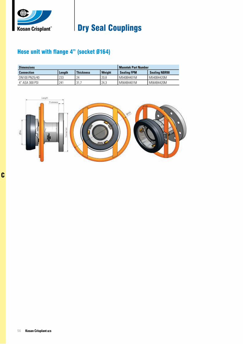
Hose unit with flange 4” (socket Ø164)
Dimensions Manntek Part NumberConnection Length Thickness Weight Sealing FPM Sealing NBR90DN100 PN25/40 233 24 20,8 M540B4401M M540B4420M4” ASA 300 PSI 241 31,7 24,3 M564B4401M M564B4420M

57
C
Emergency Shut-off Valves
Application
Normally installed as safety devices on bulk plants for bobtail or transport fill-ing operations in liquid or vapour phase.
The main feature of this kind of valve is the ability to be actuated in different ways: locally and manually by the driv-er, manual remote or pneumatic re-mote system by plant operators and automatically by cable connected to the hose in case of pull away.
Rego Part Number
Inlet & Outlet Connections
Accessories Liquid Flow Capacity at 0,68 bar drop (l/min)
Remote Pneumatic Close
Remote Pneumatic Open/Close
6016 2” F-NPT - - 26916024 3” F-NPT - - 50156010 1¼” F. NPT 6016-60D 6016-60C 980
Additionally, they incorporate a ther-mal fuse which in case of tempera-tures higher than 100ºc will melt mak-ing the valve turn to close position.
Emergency shut-off valves may be used as operation valves and replace globe or angle valves and they clearly indicate whether they are in open or closed position.
60246016
Related Documents