LOW Z-FORCE OCTASPOT™ SWEPT FRICTION STIR SPOT WELDS WELDING— CONVENTIONAL TOOL AND PROCESS DEVELOPMENT APPROACH A Thesis by Tze Jian Lam B.S.M.E., Wichita State University - 2005 Submitted to the Department of Mechanical Engineering and the faculty of Graduate School of Wichita State University in partial fulfillment of the requirements of the degree of Master of Science May 2010

Welcome message from author
This document is posted to help you gain knowledge. Please leave a comment to let me know what you think about it! Share it to your friends and learn new things together.
Transcript

LOW Z-FORCE OCTASPOT™ SWEPT FRICTION STIR SPOT WELDS WELDING—CONVENTIONAL TOOL AND PROCESS DEVELOPMENT APPROACH
A Thesis by
Tze Jian Lam
B.S.M.E., Wichita State University - 2005
Submitted to the Department of Mechanical Engineering and the faculty of Graduate School of
Wichita State University in partial fulfillment of
the requirements of the degree of Master of Science
May 2010

© Copyright 2010 by Tze Jian Lam
All Rights Reserved

iii
LOW Z-FORCE OCTASPOT™ SWEPT FRICTION STIR SPOT WELDS WELDING—CONVENTIONAL TOOL AND PROCESS DEVELOPMENT APPROACH
The following faculty members have examined the final copy of this thesis for form and content, and recommend that it be accepted in partial fulfillment of the requirement for the degree of Master of Science with a major in Mechanical Engineering. _____________________________________ George E. Talia, Committee Chair _____________________________________ Dwight A. Burford, Committee Member _____________________________________ Brian Driessen, Committee Member

iv
DEDICATION
To my parents, my sister, my brothers, my relatives, and my friends

v
ACKNOWLEDGMENTS
As a graduate research assistant in the Advanced Joining and Processing Laboratory
(AJ&PL) of the National Institute for Aviation Research at Wichita State University, I would
like to thank Dr. Dwight Burford, Director of AJ&PL, for giving me the opportunity and support
to lead the project of Low Z-Force Octaspot™ Swept Friction Stir Spot Welds Welding—
Conventional Tool and Process Development Approach (CFSP07-WSU-03). This project was
funded by the National Science Foundation’s (NSF) Center for Friction Stir Processing (CFSP),
which is part of the Industry University Cooperative Research Center (IUCRC) program.
This project work is also my thesis, as part of the requirements for completing my Master
of Science degree in Mechanical Engineering at Wichita State University. I would like to thank
my advisor and committee chair, Dr. George Talia, for his guidance, and principal investigator
and committee members, Dr. Dwight Burford and Dr. Brian Driessen, as well as Dr. Christian
Widener for their efforts and help with this thesis.
Also, I would like to recognize the hard work of students in NIAR’s AJ&PL, especially
James Gross, who developed much of the early low Z-force welding program. I would like to
thank Kristie Bixby for her editorial efforts with this thesis.
I thank the Graduate School for supporting me financially throughout my Master’s
degree. And I also thank my parents and family members for their encouragement in my studies.
vi
ABSTRACT
An investigation was conducted to develop low Z-force (normal/forge load) friction stir
spot welds (FSSWs) using conventional tooling and process development approaches. Low Z-
forces can be achieved by studying the relationship between pin tool features, geometries,
processing parameters, and resultant strength of coupons produced by friction stir spot welding
(FSSW). The effects of geometrical and feature changes of pin tool designs—including shoulder
diameters, shoulder features, probe diameters, probe shapes, and probe features—on the joint
properties of 0.040-inch-thick bare 2024-T3 aluminum alloy were evaluated. Welding tools
included Psi™, Counterflow™, Modified Trivex™, and V-flute™ pin tools. A Box-Behnken
design of experiments (DOE) approach was used to investigate the effects of three process
parameters: spindle speed, Z-force (forge load), and travel speed. The goal of the investigation
was to maintain the ultimate tensile load (UTL) in unguided lap shear coupons tested in tension
while reducing the Z-force required for producing a sound joint. This goal was achieved on a
specially built MTS Systems Corporation ISTIR PDS FSW gantry system. In addition to single-
spot unguided lap shear tests, the performance of low Z-force FSSW joints was evaluated by
optical metallographic cross-section analyses, which were then correlated with process
parameters, UTL, and pin tool designs. The maximum Z-force spikes encountered during the
initial plunge were reduced by an order of magnitude, and the Z-force processing loads were
reduced by half for Octaspot™ swept FSSW, most effectively by controlling the plunge rate
under force control. Additional reductions in Z-force were achieved by refining the conventional
FSSW tool shoulder and probe designs. Therefore, it was demonstrated that weld forces can be
reduced to the point where it would be feasible to perform robotic low Z-force FSSW for at least
some applications.

vii
TABLE OF CONTENTS
Chapter Page 1. INTRODUCTION ...............................................................................................................1
2. LITERATURE REVIEW ....................................................................................................8
2.1 FSSW Process Controls ...........................................................................................8 2.2 Development of Process Parameters ......................................................................10 2.3 Tool Geometry .......................................................................................................12 2.4 Variation of FSSW .................................................................................................13 2.5 Material Flow .........................................................................................................14
3. OBJECTIVE ......................................................................................................................16
4. TEST PROCEDURE .........................................................................................................17
4.1 Pin Tool Designs ....................................................................................................17 4.1.1 Additional Pin Tool Designs .....................................................................21
4.2 Material Preparation...............................................................................................22 4.3 Weld Setup .............................................................................................................23 4.4 Weld Programs.......................................................................................................23 4.5 Mechanical Properties Testing ...............................................................................25
5. RESULTS AND DISCUSSIONS ......................................................................................28
5.1 Achieving Low Z-Force .........................................................................................28 5.2 Concave Shoulder Tool Study (Phase 1) ...............................................................33 5.3 Concave Shoulder Diameter Study ........................................................................33
5.3.1 Psi™ Tool (0.30 Inch and 0.40 Inch) ........................................................34 5.3.2 Counterflow™ Tool (0.30 Inch and 0.40 Inch) .........................................37
5.4 Probe Design Study with 0.30-Inch-Diameter Concave Shoulder ........................41 5.4.1 Modified Trivex™ Tool ............................................................................41 5.4.2 Duo V-Flute™ Tool ...................................................................................44 5.4.3 Tri V-Flute™ Tool .....................................................................................45
5.5 Achievement in Concave Shoulder Study (Phase 1) .............................................47 5.5.1 Concave Shoulder Diameter Study ............................................................47 5.5.2 Probe Design Study....................................................................................47
5.6 Optimization Weld Parameters (DOE 2) ...............................................................51 5.7 Surface Preparation ................................................................................................54 5.8 Surface Finish ........................................................................................................55

viii
TABLE OF CONTENTS (continued)
Chapter Page
5.9 Scroll Shoulder Tool (0.30 Inch) Study (Phase 2) .................................................55 5.9.1 Achievement Duo V-Flute™ Scroll ..........................................................56
5.10 Featureless Probe Shape Study (Phase 3) ..............................................................57 5.10.1 Featureless Trivex™ ..................................................................................58 5.10.2 Featureless Pentagon™ ..............................................................................61 5.10.3 Featureless Octagon™ ...............................................................................63
5.11 Achievement in Featureless Probe Shape Study (Phase 3) ....................................65 5.12 Probe Diameter Study (Phase 4) ............................................................................66
6. CONCLUSIONS AND FUTURE WORK ........................................................................74
REFERENCES ..............................................................................................................................78
APPENDICES ...............................................................................................................................83
A. Detailed Calculation for Table 1 ............................................................................84 B. Duration of Octaspot™ Swept FSSW ...................................................................85 C. UTL Results ...........................................................................................................88

ix
LIST OF TABLES
Table Page
1. Ratio of Probe Physical Unit Volume to probe Swept Unit Volume ................................12
2. Pin Tool Matrix ..................................................................................................................20
3. Average UTL and Corresponding Z-Force Applied Using Concave Shoulder Psi™ Tool ..........................................................................................................................37
4. Average UTL and Corresponding Z-Forces Applied using Concave Shoulder Counterflow™ Tool ...........................................................................................................40
5. Compilation of DOE 1 UTL Results for Probe Design Study of 0.30-Inch-Diameter Concave Shoulder ..............................................................................................................49
6. Compilation of DOE 2 UTL Results for Probe Design Study of 0.30-Inch-Diameter Concave Shoulder ..............................................................................................................52
7. Hooking Defect of Featureless Trivex™ Pin Tool ............................................................59
8. Hooking Defect of Featureless Pentagon™ Pin Tool ........................................................61
9. Hooking Defect of Featureless Octagon™ Pin Tool .........................................................63
10. Summary of Hooking Defect and Ratio of Probe Physical to Swept Unit Volume ..........65
11. Weld Radius Compensation for Probe Radius Reduction .................................................67
12. Average UTL and Standard Deviation of DOE 1 for Probe Diameter Study ....................68
13. Z-Force Reduction and Corresponding Pin Tools and Weld Parameters ..........................73

x
LIST OF FIGURES
Figure Page
1. Friction Stir Welding (FSW) Process (courtesy of TWI). ...................................................2
2. Friction Stir Spot Welding (FSSW) Process (courtesy of Kawasaki). ................................3
3. Typical FSW Butt Joint with Fixed Pin Tool ......................................................................4
4. Typical FSW Lap Joint with Fixed Pin Tool .......................................................................4
5. Schematic Representation of Pin Tools ...............................................................................5
6. MTS System Corp. ISTIR™ PDS Five-Axis FSW Machine at AJ&PL NIAR WSU. ........................................................................................................6
7. ABB IRB 7600 Six-Axis Articulated Robot at AJ&PL NIAR WSU ..................................7
8. Schematic Diagram of Process Controls of Octaspot™ FSSW ...........................................9
9. Different Probe Shapes with Same Effective Swept Area .................................................12
10. Octaspot™ Travel Path ......................................................................................................14
11. Schematic Cross-Sectional Representation of Plunge and Swept FSSW ..........................15
12. Flat Scrolls Shoulder on Duo V-Flute™ Pin Tool: (a) 0.40-Inch Diameter and (b) 0.30-Inch Diameter.......................................................................................................18
13. Wiper™ Shoulder on Duo V-Flute™ Pin Tool: (a) 0.40-Inch Diameter and (b) 0.30-Inch Diameter.......................................................................................................18
14. Pin Tools with Five-Degree Concave Shoulder.................................................................19
15. 0.3-Inch-Diameter Probe Shapes: (a) Concave Shoulder Trivex, (b) Pentagon, and (c) Octagon. .................................................................................................................21
16. Reduced Shoulder and Probe Diameter Sizes of Duo V-Flute™ ......................................21
17. Single-Spot Unguided Lap Shear Specimen ......................................................................22
18. Experimental Weld Setup ..................................................................................................23
19. Worm Hole Defect in Octaspot™ FSSW ..........................................................................27

xi
LIST OF FIGURES (continued)
Figure Page
20. Kissing Bond Defect in Plunge FSSW ..............................................................................27
21. Sheet Lifting (left) and Hooking (right) in Lap FSW ........................................................27
22. Command and Feedback Plot for Typical Octaspot™ FSSW (Hybrid Weld Program). ....................................................................................................28
23. Command and Feedback Plot of 0.40-Inch-Diameter Psi™ Tool Welded with Position Control .................................................................................................................30
24. Command and Feedback Plot of 0.30-Inch-Diameter Psi™ Tool Welded with Position Control .................................................................................................................31
25. Command and Feedback Plot for Low Z-Force Swept FSSW ..........................................31
26. Low Z-Force Cross-Sectional Metallographic (1.2X) ...................................................... 32
27. Joint Interface of Figure 26 (100X): (a) Left Side and (b) Right Side .............................32
28. Command and Feedback Plot for Low Z-Force Swept FSSW ..........................................33
29. Main Effects Plot of 0.30-Inch-Diameter Concave Shoulder Psi™ Tool..........................34
30. Main Effects Plot of 0.40-Inch-Diameter Concave Shoulder Psi™ Tool..........................34
31. Low Z-Force Swept FSSW with 0.30-Inch-Diameter Psi™ Tool at 1,100 lbf .................35
32. Low Z-Force Swept FSSW with 0.30-Inch-Diameter Psi™ Tool at 900 lbf ....................35
33. Low Z-Force Swept FSSW with 0.30-Inch-Diameter Psi™ Tool at 700 lbf ....................35
34. Low Z-Force Swept FSSW with 0.40-Inch-Diameter Psi™ Tool at 1,100 lbf .................36
35. Low Z-Force Swept FSSW with 0.40-Inch-Diameter Psi™ Tool at 900 lbf ....................36
36. Low Z-Force Swept FSSW with 0.40-Inch-Diameter Psi™ Tool at 700 lbf ....................36
37. Main Effects Plot of 0.30-Inch-Diameter Concave Shoulder Counterflow™ Tool ..........38
38. Main Effects Plot of 0.40-Inch-Diameter Concave Shoulder Counterflow™ Tool ..........38

xii
LIST OF FIGURES (continued)
Figure Page
39. Low Z-Force Swept FSSW with 0.30-Inch-Diameter Counterflow™ Tool at 1,100 lbf .........................................................................................................................39
40. Low Z-Force Swept FSSW with 0.30-Inch-Diameter Counterflow™ Tool at 900 lbf ............................................................................................................................39
41. Low Z-Force Swept FSSW with 0.30-Inch-Diameter Counterflow™ Tool at 700 lbf ............................................................................................................................39
42. Low Z-Force Swept FSSW with 0.40-Inch-Diameter Counterflow™ Tool at 1,100 lbf .........................................................................................................................40
43. Low Z-force Swept FSSW with 0.40-Inch-Diameter Counterflow™ Tool at 900 lbf ............................................................................................................................40
44. Low Z-Force Swept FSSW with 0.30-Inch-Diameter Modified Trivex™ Tool at 1,100 lbf .........................................................................................................................42
45. Low Z-Force Swept FSSW with 0.30-Inch-Diameter Modified Trivex™ Tool at 900 lbf ............................................................................................................................43
46. Low Z-Force Swept FSSW with 0.30-Inch-Diameter Modified Trivex™ Tool at 700 lbf ............................................................................................................................43
47. Joint Interface of Figure 46 (100X): (a) Right Side and (b) Left Side ............................43
48. Plug Pull-Out Failure Mode ..............................................................................................43
49. Low Z-Force Swept FSSW with 0.30-Inch-Diameter Duo V-Flute™ Tool at 1,100 lbf .........................................................................................................................44
50. Low Z-Force Swept FSSW with 0.30-Inch-Diameter Duo V-Flute™ Tool at 900 lbf ............................................................................................................................44
51. Low Z-Force Swept FSSW with 0.30-Inch-Diameter Duo V-Flute™ Tool at 700 lbf ............................................................................................................................45
52. Joint Interface of Figure 51 (100X): (a) Right Side and (b) Left Side .............................45
53. Low Z-Force Swept FSSW with 0.30-Inch-Diameter Tri V-flute™ Tool at 1,100 lbf .........................................................................................................................46

xiii
LIST OF FIGURES (continued)
Figure Page
54. Low Z-Force Swept FSSW with 0.30-Inch-Diameter Tri V-flute™ Tool at 900 lbf ............................................................................................................................46
55. Low Z-Force Swept FSSW with 0.30-Inch-Diameter Tri V-flute™ Tool at 700 lbf ............................................................................................................................46
56. Joint Interface of Figure 55 (100X): (a) Right Side and (b) Left Side .............................46
57. Low Z-Force Swept FSSW with 0.30-Inch-Diameter Counterflow™ Tool at 700 lbf ............................................................................................................................48
58. Low Z-Force Swept FSSW with 0.30-Inch-Diameter Psi™ Tool at 700 lbf ............................................................................................................................48
59. Low Z-Force Swept FSSW with 0.30-Inch-Diameter Modified Trivex™ Tool at 700 lbf ............................................................................................................................48
60. Low Z-Force Swept FSSW with 0.30-Inch-Diameter Duo V-Flute™ Tool at 700 lbf ............................................................................................................................48
61. Low Z-Force Swept FSSW with 0.30-Inch-Diameter Tri V-Flute™ Tool at 700 lbf ............................................................................................................................49
62. UTL Results Comparison of Low Z-Force Octaspot™ Swept FSSW for Five Pin Tools with 0.30-Inch-Diameter Concave Shoulder in DOE 1 ............................50
63. UTL Results Comparison of Low Z-Force Octaspot™ Swept FSSW for Five Pin Tools with 0.30-Inch-Diameter Concave Shoulder in DOE 1 and DOE 2 ............53
64. UTL Results Comparison of Low Z-Force Octaspot™ Swept FSSW for Four Pin Tools with No Surface Preparation .....................................................................54
65. Low Z-Force FSSW with 0.30-Inch-Diameter Concave Shoulder with Half-Degree of Tilt Angle ..................................................................................................55
66. Low Z-Force FSSW with 0.30-Inch-Diameter Concave Shoulder with One-Degree of Tilt Angle ..................................................................................................55
67. Low Z-Force FSSW with 0.30-Inch-Diameter Flat Scrolls Shoulder with Half-Degree of Tilt Angle ..................................................................................................56
xiv
LIST OF FIGURES (continued)
Figure Page
68. UTL Results Comparison of Low Z-Force Octaspot™ Swept FSSW for 0.30-Inch-Diameter Scroll Shoulder Duo V-flute™ in DOE 2 .........................................57
69. Featureless Trivex™ Cross-Sectional Metallographic M19 ..............................................59
70. Right Side of Figure 69 with 0.015 Inch Hooking Defect .................................................59
71. Left Side of Figure 69 with 0.013 Inch Hooking Defect ...................................................60
72. Featureless Pentagon™ Cross-Sectional Metallographic M19 .........................................61
73. Right Side of Figure 72 with 0.005 Inch Hooking Defect .................................................62
74. Left Side of Figure 72 with 0.002 Inch Hooking Defect ...................................................62
75. Featureless Octagon™ Cross-Sectional Metallographic M19 ...........................................63
76. Right Side of Figure 75 with 0.009 Inch Hooking Defect. ................................................64
77. Left Side of Figure 75 with 0.008 Inch Hooking Defect. ..................................................64
78. Metallographic Image of CFSP09307_6_M21 ..................................................................69
79. Metallographic Image of CFSP09307_6_M17 ..................................................................69
80. Metallographic Image of CFSP09307_6_M19 ..................................................................69
81. Metallographic Image of CFSP09307_6_M23 ..................................................................69
82. Metallographic Image of CFSP09307_12_M20 ................................................................71
83. Right Side of Nugget in Figure 82 .....................................................................................72

xv
LIST OF ABBREVIATIONS/NOMENCLATURES
AJ&PL Advanced Joining and Processing Laboratory
CFSP Center for Friction Stir Processing
CNC Computer Numerically Controlled
DFT Discrete Fourier Transformation
DOE Design of Experiment
FSP Friction Stir Processing
FSW Friction Stir Welding/Weld
FSSW Friction Stir Spot Welding/Weld
GKSS Gesellschaft zur Förderung der Kernenergie in Schiffbau und Schiffstechnik (German: Society for the Promotion of the Nuclear Energy in Shipbuilding and Naval Technology)
HAZ Heat-Affected Zone
HCl Hydrochloric Acid
HF Hydrofluoric Acid
HNO3 Nitric Acid
HRS High Rotational Speed
IRB Industrial Robot
ISTIR™ Intelligent Friction Stir Welding for Research and Production
IUCRC Industrial University Cooperative Research Center
LOP Lack of Penetration
NIAR National Institute for Aviation Research
NSF National Science Foundation
PDS Process Development System

xvi
LIST OF ABBREVIATIONS/NOMENCLATURES (continued)
PFSW Plunge Friction Spot Welding/Weld
RPT Retractable Pin Tool
SEM Scanning Electron Microscope
TMAZ Thermomechanically Affected Zone
TWI The Welding Institute
UTL Ultimate Tensile Load

1
CHAPTER 1
INTRODUCTION
Friction stir welding (FSW) was patented by The Welding Institute (TWI) in England in
1991 [1]. FSW is a solid-state joining technology, which differs from conventional fusion
welding in that the joining process occurs below the melting temperature of the welded material
[2,5]. This new joining process is especially beneficial on materials such as 2XXX and 7XXX
series aluminum alloys, which are relatively difficult to join by conventional fusion welding. The
use of aluminum alloys in automotive and aerospace industries gained popularity because of
their high strength-to-weight ratio, resistance to corrosion, energy savings, etc. [3,4]. In recent
years, research and development of FSW technology has made significant progress toward
understanding the fundamentals of this joining technology [5].
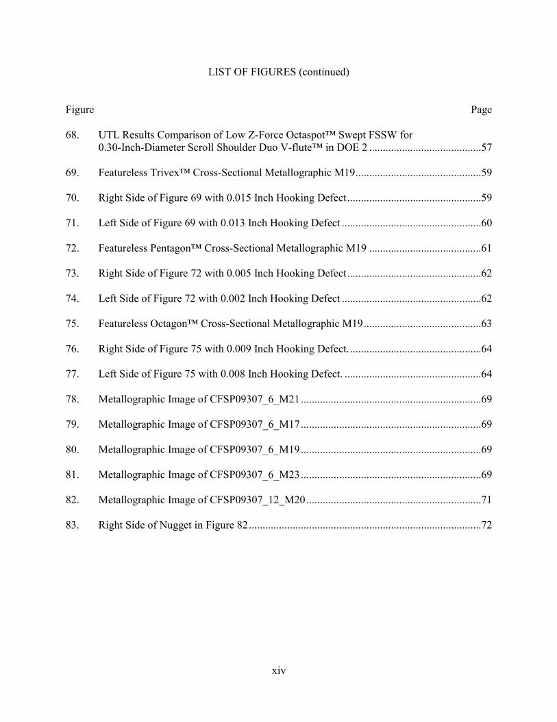
The FSW process consists of four stages: rotate, plunge, translate, and retract. FSW was
introduced as a linear weld with a non-consumable pin tool, which rotates about its own axis,
plunges into a weld specimen to a specified depth, translates in a linear or curvilinear path along
the joint line, and retracts at the end of weld path (Figure 1). With this process, welding can
occur in a butt or lap joint configuration. One of FSW’s main variants is friction stir spot welding
(FSSW), which is similar to FSW only without the translation of a pin tool. FSSW is mainly
applied in lap joint configurations with only three stages: rotate, plunge, and retract (Figure 2).
The simplest form of FSSW, called poke or plunge FSSW, was patented by Mazda in 2003 [6] as
―plunge‖ friction spot welding (PFSW) [20]. Other variants of FSSW are Squircle™ [7],
Octaspot™ [25-28, 30-33], Stitch-FSW [5] or Stitch-FSSW from Gesellschaft zur Förderung der
Kernenergie in Schiffbau und Schiffstechnik (GKSS) [4,8,9], and swing-FSW [5] or swing-
FSSW from Hitachi [4,10,11,12], which increases the joint shear area. Another variant of FSSW

2
relates to the exit hole that is left when the pin tool retracts; thus, a process called ―refill‖ FSSW
solves the issue by refilling the exit hole. The process of refill FSSW has been patented in Japan
[13] and in the United States [24]. Another variant of FSW, friction stir processing (FSP), was
developed to exploit the benefit of the FSW process to change the microstructure of cast
materials to a void-free and fully recrystallized fine grain microstructure found in the weld
nugget of FSW [2,5,14].
Figure 1. Friction Stir Welding (FSW) Process (courtesy of TWI).
3
(a) Rotate (b) Plunge (c) Retract
Figure 2. Friction Stir Spot Welding (FSSW) Process (courtesy of Kawasaki). The microstructures of FSW and FSSW weld zones use the same terms: weld nugget,
thermomechanically affected zone (TMAZ), heat-affected zone (HAZ), and unaffected zone or
parent material (Figure 3). The weld nugget, also called the stir zone, is the zone that the probe
has occupied and significantly processed, producing a fine, fully recrystallized grain structure.
The TMAZ is the zone that receives some limited plastic deformation and is significantly
affected by the thermal cycle of the process, while the HAZ experiences a thermal cycle that is
only significant enough to change the properties and microstructure of the material. Finally, the
unaffected zone experiences a minimal thermal cycle, which is not significant enough to change
the microstructure or mechanical properties [2]. Also, a small amount of asymmetry occurs
transverse to the weld direction. The advancing side of the weld panel (left side of Figure 1)
occurs when the tool rotation direction is the same as the tool travel direction, whereas, the
retreating side of weld panel (right side of Figure 1) is found on the side where the tool rotation
direction is opposite the tool travel direction.
The advancing side of a transverse metallographic sample is shown in Figure 3. The
right side of this figure has a clear distinctive line between the TMAZ and HAZ, but on the
retreating side, there is no such clearly discernible line between the TMAZ and HAZ. The weld

4
nugget properties, such as fatigue, deformation, and tensile load, are generally superior to the
surrounding parent material due to the nugget’s fine grain microstructure [2]. In a typical FSW
lap joint configuration, the weld zones mentioned above can also be observed, as shown in
Figure 4.
Figure 3. Typical FSW Butt Joint with Fixed Pin Tool.
Figure 4. Typical FSW Lap Joint with Fixed Pin Tool.
Conventional FSW tools are non-consumable pin tools, which consist of a body, a
shoulder, and a probe or pin. These tools are also known as fixed-pin tools, where the length of
the probe is fixed (Figure 5a). Bobbin tools, also known as self-reacting pin tools, consist of
three parts: an upper shoulder, a probe, and a lower shoulder (Figure 5c). Self-reacting pin tools
eliminate the potential for lack of penetration (LOP) in the weld and apply minimal net force
normal to the part assembly, since the down force of the upper shoulder is opposed by the
upward force of the lower shoulder. Similarly, FSSW typically uses fixed pin tools but also uses
refill or retractable FSSW pin tools, which consist of an independently moveable probe and
shoulder with an optional containment ring (Figure 5b). The probe of FSW or FSSW tools
typically consists of different features such as threads, flutes, and/or flats, which help to channel
the flow of material. In order to promote material movement, the shape of the probe can be in the
Nugget
Parent Material
Parent Material
HAZ HAZ
TMAZ TMAZ Advancing Side
Retreating Side
Nugget
Parent Material
Parent Material
HAZ HAZ TMAZ TMAZ
Advancing Side
Retreating Side

5
form of a circle, triangle, square, pentagon, etc.. The shoulder captures material displaced by the
probe and exerts a forging force (normal load) to consolidate the material. The body of the pin
tool is inserted into the pin tool holder, which is attached to the forge spindle of the FSW
machine. The probe of both retractable and self-reacting pin tools is attached to an independent
pin axis in an FSW machine in order to control pin force and pin position separately from the
forge axis.
Figure 5. Schematic Representation of Pin Tools.
Applications and designs lead to various definitions of pin tools such as fixed pin tool or
conventional pin tool, retractable pin tool or refill pin tool (RPT), and self-reacting pin tool or
bobbin pin tool. A fixed pin tool is where the probe and shoulder do not move relative to each
other (Figure 5a), whereas in a retractable pin tool, the probe and shoulder can move relative to
each other along the axis of tool rotation (Figure 5b) [15]. A fixed pin tool leaves an exit hole at
the end of the weld, whereas a retractable pin tool is designed not to produce an exit hole. The
relative motion of the probe and shoulder in an RPT tool set enables it to refill the exit hole. A
self-reacting pin tool has an additional lower shoulder attached to the probe, and both the upper
shoulder and lower shoulder create a nominally zero net force while clamping the weld material
Body
Probe
Shoulder
Upper Shoulder
Probe
Body
Lower Shoulder
(a) Fixed Pin Tool (b) Retractable Pin Tool (c) Self-Reacting Pin Tool
Containment Ring

6
to keep it from escaping from the joining region (Figure 5c) [17]. The design of a self-reacting
pin tool requires no backing anvil, eliminates the lack of penetration defect, and increases the
travel speed due to heating from both shoulders [16,17].
FSW machines are usually gantries for stiffness, with three to five-axes of motion for
two- or three-dimensional welding, position and load control capability, and intelligence and
sensing capability. The multi-purpose gantry FSW machine used in this study was an MTS
Systems Corporation’s ISTIR™ Process Development System (PDS) (Figure 6), which is
capable of a wide range of process development parameters such as high Z-force (normal load)
up to 20 kip with the stiffness of the gantry system.
Figure 6. MTS System Corp. ISTIR™ PDS Five-Axis FSW Machine
at AJ&PL NIAR WSU. This FSW machine can be programmed using position control, load control, or a combination of
both. The intelligence and sensing capability enables the capture of data on weld parameters and
feedback forces that can be analyzed to ensure weld quality. Articulated-arm robots equipped for
7
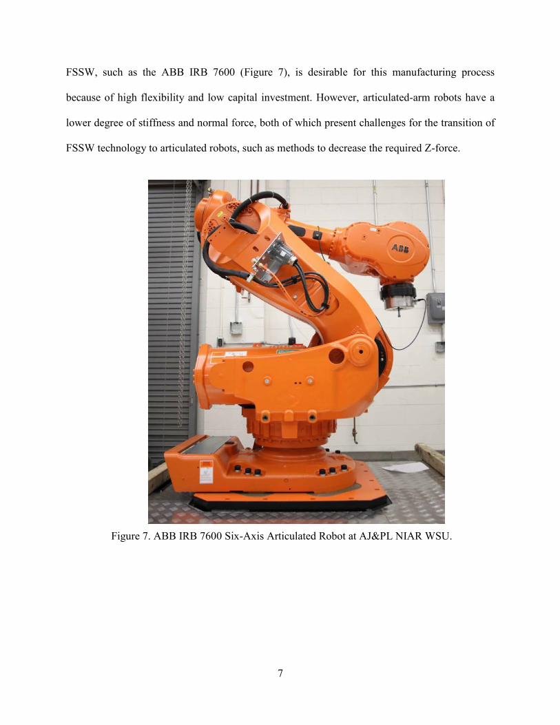
FSSW, such as the ABB IRB 7600 (Figure 7), is desirable for this manufacturing process
because of high flexibility and low capital investment. However, articulated-arm robots have a
lower degree of stiffness and normal force, both of which present challenges for the transition of
FSSW technology to articulated robots, such as methods to decrease the required Z-force.
Figure 7. ABB IRB 7600 Six-Axis Articulated Robot at AJ&PL NIAR WSU.

8
CHAPTER 2
LITERATURE REVIEW
2.1 FSSW Process Controls
The process controls of FSSW have improved over the decades with the advancement of
computing, sensing, and measuring. Advancement in machining technology directly benefits
FSSW because, from its inception, FSW was developed using computer numerically controlled
(CNC) machines. The more capabilities of FSSW machines mean that the more varieties of
process controls can be developed.
Position control is normally applied to FSSW. This is the simplest process control and
requires the least amount of processing monitoring by the machine controller. A position control
weld program uses a command of known weld depths to maintain a constant tool depth
throughout the weld (Figure 8a) [4,18]. Another process control of FSSW is load control, which
involves a force-feedback process. It requires more intelligence for measuring, sensing,
feedback, and command controls for loading and positioning. A load-control weld program
begins by establishing a nominal load command based on a feedback load obtained from a
preliminary weld using a position-control weld program. This load is typically maintained at a
constant load throughout the weld (Figure 8b) [4,18]. Variation of FSSW process control can be
a combination of position control and load control, known as hybrid control. The hybrid-control
weld program operates with the position control as the initial command control, beginning with
the plunge step controlled to a specified weld depth. Once the plunge phase is complete, the
program switches to load control as command control to maintain a predetermined constant
forging load during the weld (Figure 8c) [26].

9
Time
Val
ue
Load
Position
Time
Val
ue
Load
Position
Time
Val
ue
Load
Position
Command Feedback (a) Position Control (b) Load Control (c) Hybrid Control
Figure 8. Schematic Diagram of Process Controls of Octaspot™ FSSW.
The feedback reaction force of a position-control weld program increases during the
plunge stage, due to displacement of material when the probe is plunged into the joint material,
and increases significantly when the tool shoulder comes in contact with the top surface of the
joint material. As the pin tool is moved in the Octaspot™ path, if the weld coupon has irregular
thickness or if the backing fixture is uneven, a position control weld will produce poor weld
quality due to not maintaining a sufficient forging force (Figure 8a). Since the Z-force acts as the
forging force, which is an important factor to ensure a fully consolidated weld, load control as
command control can ensure a constant load level throughout the weld. However, the increased
position of the pin tool that travels causes lifting because the predetermined load is low (Figure
8b) [Note: the position values in Figures 8b and 8c can be either negative, when the tool plunges
into the material (predetermined load too high), or positive, when the tool rises above the
material (predetermined load too low)]. In the hybrid-control weld program, position control is
utilized to ensure that a sufficient weld depth is reached in the plunge stage of the weld; then the
program is changed to load control to ensure a consistent forging force for the rest of the weld.
However, the high-reaction load due to the control position during the plunge phase is not
favorable for low Z-force FSSW research. A low Z-force weld program based on load control is

10
used to eliminate high-reaction loads, known as Z-force spikes, in the plunge step of the weld
(Figure 8a and 8c).
2.2 Development of Process Parameters
The process parameters of Octaspot™ swept FSSW are similar to FSW and include
spindle speed (rpm), travel speed (ipm), plunge speed (ipm), tilt angle (degree), dwell time (sec),
and forge load or normal load (lbf). The process parameters of plunge FSSW include spindle
speed, plunge speed, and dwell time, whereas an Octaspot™ swept FSSW has a closed-loop path
(Figure 10) involving the additional process parameters of travel speed and tilt angle. A hybrid-
control weld program (Figure 8c) includes the initial plunge under position control and the tool
movement under load control.
In a low Z-force weld program, plunge depth is defined by a constant-plunge spindle
speed and a constant-plunge dwell time, both introduced to reach specific plunge depth within a
range of low forge load. For a low Z-force weld program developed from the hybrid-control
weld program of Octaspot™ swept FSSW, all process parameters are held constant. These
include the tilt angle, dwell time, plunge speed, plunge dwell time, and plunge spindle speed. For
this research, the effects of variation and interaction of process parameters such as normal load,
weld spindle speed, and travel speed are of main interest for characterizing the weld properties of
low Z-force Octaspot™ swept FSSW.
Each process parameter has its own role; therefore, the investigation of certain, more
significant process parameters is more desirable for research that is constrained by time and
budget. Since three factors (k = 3) or process parameters were selected for this study, two general
design of experiments (DOEs), either two-level with k factors (2k) or three-level with k factors
(3k) designs are appropriate DOEs. A three-level DOE with 27 runs has a higher resolution than a

11
two-level DOE with 8 runs. In addition, a three-level DOE can be a second-order model.
However, a three level DOE will increase the cost and time. A model that provides a response
surface can be used to optimize the process parameters for maximizing the ultimate tensile load
(UTL) of lap shear coupons. Therefore, statistical development of process parameters using a
response surface method, such as a Box-Behnken DOE, can significantly reduce time and cost
compared to a full factorial DOE. For example, a Box-Behnken or Central Composite DOE has
only 15 or 16 runs, compared to 27 runs in a three-level full design with three factors 33.
Compared to a Box-Behnken DOE, a Central Composite DOE contains points on the corners of
the design space cube, which can represent factor-level combinations that are either expensive or
impossible to test because of physical process constraints [19]. In certain situations, these corner
points can be extreme process parameters, which ultimately can damage the pin tools.
The three process parameters chosen as the main interest of investigation in this study
were selected because FSSW was treated as a thermo-mechanical controlled process. Weld
spindle speed and travel speed are controlled variables in a weld program, and they directly
affect thermal input to the work piece [2, page 71]. The term ―cold‖ weld is typically associated
with a weld that is made with a relatively high travel speed and low spindle speed. A ―hot‖ weld
is typically described as a weld with a relatively low travel speed and high spindle speed. These
relative terms of cold and hot welds do not correlate with peak temperature [2, page 37]. One
would assume a ―hot‖ weld should reach a higher peak temperature compared to a cold weld, but
the high conductivity of aluminum tends to disperse the heat of a ―hot‖ weld because of the slow
travel speed, thus resulting in a lower peak temperature. A final controlled variable chosen to be
investigated in this study was normal load because a ―controlled path extrusion‖ [2 pp 301,20]

12
FSSW need a consistent normal load to produce a good FSSW joint. All other process
parameters were kept constant in this research but may be investigated in future work.
2.3 Tool Geometry
FSW and FSSW tools have similar characteristics, such as body, shoulder, and probe
(Figure 5), which may have a range of different features and shapes. Features on the probe, such
as flats, flutes, and threads, can promote the flow of material around the probe. A concave
shoulder traps material that is displaced by the probe. A shoulder with a flat face and scrolls will
tend to capture the material displaced by the probe and redirect it inward toward the probe.
Probes with different cross-sectional shapes are shown in Figure 9. These shapes serve to
change the ratio of the physical volume of the probe to the swept volume of the probe. Table 1
provides the volume per unit length (or unit volume) of each probe.
(a) (b) (c) (d) (e) (f) (g)
Figure 9. Different Probe Shapes with Same Effective Swept Area: (a) Rectangular, (b) Triangular, (c) Square, (d) Pentagon, (e) Hexagon, (f) Octagon,
and (g) Circular
TABLE 1
RATIO OF PROBE PHYSICAL UNIT VOLUME TO PROBE SWEPT UNIT VOLUME
Probe Shape
a b c d e f g Probe Physical Unit Volume 0.010 0.013 0.020 0.024 0.026 0.028 0.031
Ratio of Probe Physical to Swept Unit Volume
0.308 0.413 0.637 0.757 0.827 0.900 1.000
Detailed calculation refers to Appendix A.

13
In plunge FSSW, the plunge stage creates a hooking defect at the lap joint interface due
to displacement of the probe’s volume of material. In addition, features on the probes, such as
threads, which provide an augering effect that causes material to recirculate toward the shoulder,
further increase the lifting and hooking, and create a large weld nugget. However, the Octaspot™
swept FSSW process includes a closed-loop path that consumes the hooking feature and
simultaneously creates a larger stir zone compared to the plunge FSSW process.
The shoulder of a pin tool has three main functions: (1) to capture material displaced by
the probe, (2) to apply Z-force or forging force, and (3) to create frictional heat. Shoulder
features, such as flat scroll or Wiper™ [21] (Figure 12 and Figure 13), are designed to capture
material and direct it toward the probe. A concave shoulder (Figure 14), which has a small
pocket of volume, captures the displaced material and keeps it pressed against the probe.
For thin-gage material, an optimum shoulder diameter is favorable to create adequate
frictional heat and avoid a large heat-affected zone. A large shoulder diameter creates a wider
HAZ, compared to a small shoulder diameter. Since low Z-force is the primary goal of this
research, the pin tool shoulder diameter needs to be reduced for low process forces but yet
provide sufficient forging force to ensure consolidation of the weld nugget. A large shoulder
diameter requires more Z-force compared to a small shoulder diameter to create similar forging
pressure for sufficient consolidation of the weld nugget.
2.4 Variation of FSSW
Existing fastening methods such as rivets and resistance spot welds have been widely
applied in the automotive and aerospace industries for decades. FSSW has been introduced
recently as an alternative fastening method for thin-gauge materials. The simplest type of FSSW,
referred to as plunge FSSW or poke FSSW, is an attractive alternative replacement for existing

14
discrete fastening methods because it can be produced rapidly and with a simple motion. Plunge
FSSW has shown many benefits and already has been implemented in the automotive industry
[22]. Besides plunge spots, refill FSSW can fill the exit hole and leave a nearly flush surface
with an opposing pin and shoulder [23,24]. Swept FSSW, such as the Squircle™ disclosed by
TWI [7] and developed at Wichita State University (WSU) as an Octaspot™, has been shown to
be up to 250 percent stronger than rivets and resistant spot welds in a single-spot lap shear [25].
Plunge and refill FSSW differ from swept FSSW. Swept FSSW has an additional closed-loop
translation movement (Figure 10). This closed-loop translation increases the joint shear area and
has been demonstrated at WSU to have better mechanical properties compared to plunge or refill
FSSW [7,26,27,33].
1) Plunge 2) Move Out 3) Begin Sweep
4) Perimeter Undulation 5) Complete Sweep 6) Move In & Retract
1) Plunge 2) Move Out 3) Begin Sweep
4) Perimeter Undulation 5) Complete Sweep 6) Move In & Retract
Figure 10. Octaspot™ Travel Path.[25,27]
2.5 Material Flow
Plunge FSSW cross-sections tend to exhibit an upward flow of material from the bottom
sheet causing an uplift of the faying surface, called hooking. The hooking caused by the vertical
translation of material creates a thinning of the effective thickness of the top sheet. In contrast,

15
swept FSSW consumes the hook by sweeping around the perimeter, giving it better control of the
faying surface geometry and increasing the effective shear area of the nugget (Figure 11).
Plunge (Poke) Spot
Swept Spot
Figure 11. Schematic Cross-Sectional Representation of Plunge and Swept FSSW.[26]
For single-pass linear FSW lap welds, placing the advancing side or retreating side in the
load path significantly affects the mechanical properties measured by the unguided lap shear
coupons [26,29]. Hooking is typically observed on the advancing side of lap welds and sheet
lifting along the retreating side of lap welds (Figure 21). Both defects can be significantly
affected by probe design. Prior related work involving the Counterflow™ tool was found to
produce excellent unguided lap shear mechanical properties on both the advancing side and
retreating side when placed directly on the loading path [29].
In making an Octaspot™ swept FSSW, the advancing side is typically placed directly on
the loading path because it produces a clearly distinctive line between the TMAZ and HAZ [26].
This distinctive line on the advancing side is placed on the outside of the Octaspot™ swept
FSSW weld nugget to ensure that there is no sheet thinning or hooking around the joint. In this
study, the retreating side of an Octaspot™ swept FSSW was placed inside the weld nugget and
not directly subjected to a tensile lap-shear test load. The hooking defect on the advancing side
and joint interface oxide remnant line (sheet lifting) on the retreating side can be eliminated by
appropriate probe designs.

16
CHAPTER 3
OBJECTIVE
Friction stir spot welding development work has commonly been used on a gantry-type
system because of the wide range of Z-forces, also known as ―forging forces‖ or ―normal
forces,‖ required to produce a sound FSSW. However, articulated robots, which are limited to
lower Z-forces, are preferred for implementation in manufacturing plants because of their
potential to produce three-dimensional structures with more flexibility and lower capital costs
than a conventional gantry system. Thus, for robotic applications, an investigation into low Z-
force FSSW using conventional tools and process development is crucial for the development of
this technology. Lower Z-forces can be achieved by studying the relationship between pin tool
features, geometries, and process parameters measured by UTL, and optical metallographic
cross-sections. FSSW must maintain a significant joint strength with lower Z-force and be
comparable to existing FSSW joint strength. The weld cycle time must be minimized to achieve
a lower manufacturing time and thus be competitive with other fastening technologies. This
research helps to indentify the portability issues associated with moving FSSW technology from
gantries to robots and provides a path for implementation of FSSW utilizing articulated robots in
the automotive and aerospace industries.

17
CHAPTER 4
TEST PROCEDURE
4.1 Pin Tool Designs
A conventional fixed-pin tool design used for a lap-joint weld requires an adequate probe
length to penetrate through the first sheet of material and partially breaking the surface interface
of the second sheet material to create a joint. Whereas, a lap-joint weld with different material
thicknesses to be welded required a two-piece pin tool, a body, and a detachable probe with
different probe lengths or a retractable pin tool. In this study, a conventional pin tool with a fixed
probe length will be utilized to lap weld bare aluminum alloy 2024-T3 sheet with a thickness of
0.040 inch. Since AJ&PL has ongoing research involving short, continuous, linear FSW and
Octaspot™ swept FSSW lap weld joints using a similar thickness of material, a few existing pin
tool designs were utilized in this research. A comparison of existing data with low Z-force data
on mechanical properties such as single-spot unguided lap shear weld UTL were analyzed based
on Z-forces and pin tool designs.
Each pin tool has a few unique features designed on the probe such as threads, flutes, and
flats. A new pin tool design has two opposing flutes and resembles the letter V in the alphabet;
hence, it is named the V-flute™ (Figure 12). Typical shoulder designs are concave, flat, and
convex. In this experiment, pin tools were designed with a five-degree concave shoulder with no
features. The material displaced by the probe in the plunge process was captured mostly under
the concave shoulder. Another pin tool shoulder was designed with grooved features on a flat
shoulder, hence named flat scrolls, and was used in this experiment to capture displaced material,
scooping and directing it toward the center of the pin tool (Figure 12). Another variant of the flat
scrolls without the exiting pin tool shoulder lip, called the Wiper™ (Figure 13a), was considered

18
in the design stage. However, a reduction of the shoulder diameter from 0.40 inch to 0.30 inch
(Figure 13b) prevented its use, and the flat scrolls design with a similar shoulder feature (Figure
12b) was used instead.
(a) (b) Figure 12. Flat Scrolls Shoulder on Duo V-Flute™ Pin Tool: (a) 0.40-Inch Diameter and
(b) 0.30-Inch Diameter.
(a) (b)
Figure 13. Wiper™ Shoulder on Duo V-Flute™ Pin Tool: (a) 0.40-Inch Diameter and (b) 0.30-Inch Diameter.
Five pin-tool designs were included in this research. Three pin tools were extensively
investigated for short linear lap FSW, plunge FSSW, and Octaspot™ swept FSSW. Two
preferred pin tools for Octaspot™ swept FSSW were the Counterflow™ [28,29,30,31] and Psi™
tool [25,30,31,32,33] designs developed at WSU, whereas a Modified Trivex™ tool [26,30,31]
has been shown to be successful for plunge and Octaspot™ FSSW (Figure 14a to 14f). In
addition, a new pin tool design named the V-flute™ [30]—Tri V-flute™ and Duo V-flute™
(Figure 14g to 14j)—was included in this research. A Tri V-flute™ pin tool has three sets of V-
flutes™ and a Duo V-flute™ has two sets of V-flutes™. The two designs were developed to
study the effects of multiples V-flutes on UTL joint strengths for an Octaspot™ swept FSSW.
Two pin tool shoulder diameters of 0.30 inch and 0.40 inch were included in this research to
investigate the effects of shoulder sizes on Z-force applied, corresponding to the UTL of joint
19
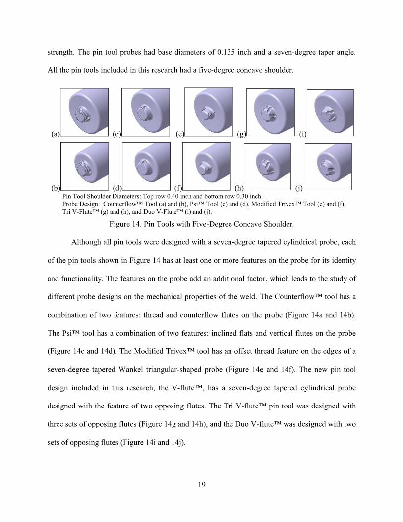
strength. The pin tool probes had base diameters of 0.135 inch and a seven-degree taper angle.
All the pin tools included in this research had a five-degree concave shoulder.
(a) (c) (e) (g) (i)
(b) (d) (f) (h) (j) Pin Tool Shoulder Diameters: Top row 0.40 inch and bottom row 0.30 inch. Probe Design: Counterflow™ Tool (a) and (b), Psi™ Tool (c) and (d), Modified Trivex™ Tool (e) and (f), Tri V-Flute™ (g) and (h), and Duo V-Flute™ (i) and (j).
Figure 14. Pin Tools with Five-Degree Concave Shoulder.
Although all pin tools were designed with a seven-degree tapered cylindrical probe, each
of the pin tools shown in Figure 14 has at least one or more features on the probe for its identity
and functionality. The features on the probe add an additional factor, which leads to the study of
different probe designs on the mechanical properties of the weld. The Counterflow™ tool has a
combination of two features: thread and counterflow flutes on the probe (Figure 14a and 14b).
The Psi™ tool has a combination of two features: inclined flats and vertical flutes on the probe
(Figure 14c and 14d). The Modified Trivex™ tool has an offset thread feature on the edges of a
seven-degree tapered Wankel triangular-shaped probe (Figure 14e and 14f). The new pin tool
design included in this research, the V-flute™, has a seven-degree tapered cylindrical probe
designed with the feature of two opposing flutes. The Tri V-flute™ pin tool was designed with
three sets of opposing flutes (Figure 14g and 14h), and the Duo V-flute™ was designed with two
sets of opposing flutes (Figure 14i and 14j).

20
The matrix of the pin tools had a combination of two shoulder sizes and two shoulder
features, and the five probe designs created a total of 20 pin tools (Table 2). Thus, this research
was divided into two phases: that involving the concave shoulder (phase 1) and that involving
the flat scrolls (phase 2). Phase 1 involved the pin tool matrix with two different shoulder
diameters to study the effects of shoulder diameter on Z-forces and five probe designs to study
the effects of probe designs on mechanical properties. However, the Modified Trivex™, Tri V-
flute, and Duo V-flute™ tools with 0.40-inch-diameter shoulders in phase 1 and all 0.40–inch-
diameter shoulders in phase 2 were not made because the 0.40-inch-diameter shoulder required a
higher Z-force. In phase 2, the pin tool matrix was reduced to one probe design (Duo V-flute™)
to study the effects of the flat scrolls shoulder feature and the concave shoulder feature on the
0.3-inch-diameter shoulder on mechanical properties (UTL).
TABLE 2
PIN TOOL MATRIX
Phase 1 studyPhase 2 study
Pin tools not made
Shoulder Diameter Counterflow Trivex PSI Tri V-Flute 0.3 inch 0.4 inch
Counterflow Trivex PSI Tri V-Flute 0.3 inch 0.4 inch
Duo V-Flute
Scroll
Duo V-Flute
Concave

21
4.1.1 Additional Pin Tool Designs
Further investigation led to a phase 3, which consisted of three probe shape designs with
no features on the probe: Wankel’s triangular-shaped probe, called Trivex™ (Figure 15a); the
pentagon-shaped probe, called Pentagon™ (Figure 15b); and the octagon-shaped probe, called
Octagon™ (Figure 15c) with a 0.135-inch-diameter probe base and 0.30-inch-diameter five-
degree concave shoulder. This additional investigation studied the relationship between the ratio
of physical volume to swept volume and the hooking defect of Octaspot™ swept FSSW.
The Duo V-flute™ pin tool design was selected to further reduce the Z-force from a
0.40–inch-diameter shoulder with a 0.135-inch-diameter probe (Figure 16a), to a smaller 0.30-
inch-diameter shoulder with a 0.135-inch-diameter probe (Figure 16b), to a phase 4 study, which
was the final design of a small 0.25-inch-diameter shoulder with a small 0.10-inch-diameter
probe (Figure 16c). This additional investigation, which studied the relationship between two pin
tools, as shown in Figure 16b and 16c, reduced the effects of shoulder and probe diameters on Z-
force and UTL of Octaspot™ swept FSSW.
(a) (b) (c) Figure 15. 0.3-Inch-Diameter Probe Shapes: (a) Concave Shoulder Trivex, (b) Pentagon,
and (c) Octagon.
(a) (b) (c)
Figure 16. Reduced Shoulder and Probe Diameter Sizes of Duo V-Flute™.
22
4.2 Material Preparation
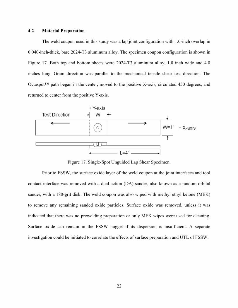
The weld coupon used in this study was a lap joint configuration with 1.0-inch overlap in
0.040-inch-thick, bare 2024-T3 aluminum alloy. The specimen coupon configuration is shown in
Figure 17. Both top and bottom sheets were 2024-T3 aluminum alloy, 1.0 inch wide and 4.0
inches long. Grain direction was parallel to the mechanical tensile shear test direction. The
Octaspot™ path began in the center, moved to the positive X-axis, circulated 450 degrees, and
returned to center from the positive Y-axis.
Figure 17. Single-Spot Unguided Lap Shear Specimen.
Prior to FSSW, the surface oxide layer of the weld coupon at the joint interfaces and tool
contact interface was removed with a dual-action (DA) sander, also known as a random orbital
sander, with a 180-grit disk. The weld coupon was also wiped with methyl ethyl ketone (MEK)
to remove any remaining sanded oxide particles. Surface oxide was removed, unless it was
indicated that there was no prewelding preparation or only MEK wipes were used for cleaning.
Surface oxide can remain in the FSSW nugget if its dispersion is insufficient. A separate
investigation could be initiated to correlate the effects of surface preparation and UTL of FSSW.

23
4.3 Weld Setup
All FSSW setups were made with a five-axis ISTIR™ PDS FSW machine from the MTS
Systems Corporation. Welding was supported with a 0.50-inch-thick steel backing plate with a
0.040-inch machined step for lap welds (Figure 18). Steel bars were spaced 0.75 inch apart,
clamped with finger clamps spaced 6.0 inches apart, and tightened with a torque wrench to 40 ft-
lbf, providing approximately 900 lbf down force. The weld fixture position was set up so that the
lower sheet was on the positive X-axis side of the machine, and the start of the first spot through
the fifteenth spot from negative to positive was on the Y-axis (Figure 18). In this setup, the
metallographic cross-section of each spot was consistently processed (Note: Steel backing
support was removed from time to time to accommodate other projects).
0.04” Spacer
0.5” x 1” 4130 Steel Bar
~ 900 lbf
0.04”2024-T3
0.75”~ 900 lbf
4130 Steel Backing Support
0.04”2024-T3
+ X-axis
+ Y-axis into slide
Figure 18. Experimental Weld Setup.
4.4 Weld Programs
Weld programs used on the MTS FSW machine were written using a combination of load
control and position control. This capability of the MTS software provides an advantage to
researchers to further investigate FSSW with low Z-force with innovative weld schedules tested
in this research. The first weld program utilized position control, which commanded the pin tool
to plunge into the weld coupon at a specified depth. The second weld program utilized a hybrid
weld program with a partial initial plunge using position control and then switched to load
control for the remainder of the weld. In addition to controlling maximum weld forces, load-

24
control FSSW has been shown to have more consistent ultimate tensile load results with lower
standard deviations [26]. However implementation of a full load-control weld program has a few
obstacles with which to be concerned, such as uncontrolled plunge depth and weld program
modification. Modification of the weld program to load control introduced additional parameters,
such as plunge dwell time and plunge spindle speed. However, the weld program was modified
with minimal changes, and most of the constant values remained the same.
Process parameters vary in a weld program and depend on the types of FSSW. In plunge
FSSW, the main process parameters are spindle rotational speed, plunge speed, plunge depth,
and dwell time. In a hybrid weld program written for Octaspot™ FSSW, additional process
parameters included in the hybrid weld program are travel speed, tilt angle, spot radius, and Z-
force. A low Z-force weld program modified from a hybrid weld program introduced a new
process parameter, plunge spindle speed, and substituted dwell time with plunge dwell time and
removed the plunge depth. Selecting which process parameters to hold constant and which to be
varied requires a literature review on process parameters. The process parameters selected to be
varied in this research were spindle speed, travel speed, and forge load. The process parameters
matrix used a Box-Behnken DOE approach to determine the process parameters window and the
significance of each process parameter with response to ultimate tensile load of Octaspot™-
FSSW.
Since the hybrid weld program has a position control in the plunge section, feedback of
the normal load spiked up to 3,000 lbf at the time of pin tool shoulder contact with the weld
coupon. Prior to changing the hybrid weld program to the low Z-force weld program, several
solutions were suggested to reduce the spike of the Z-force feedback. Pre-welding solutions
suggested for reducing normal load, such as preheating and predrilling the weld coupon, were

25
not practical and not tested. However, modification of the process parameters, such as reducing
the plunge speed, reducing the plunge depth, increasing the spindle speed, and increasing the
dwell time, were more practical solutions.
The position-control weld program was utilized to approximate the Z-force value for the
load-control weld program from feedback force data. Three selected process parameters were
varied using the Box-Behnken DOE approach and run with the low Z-force weld program to
investigate the effect of process parameters and pin tools designs on the mechanical properties of
low Z-force Octaspot™ FSSW.
4.5 Mechanical Properties Testing
There are two different types of mechanical properties tests: destructive and non-
destructive. Destructive tests, such as the tensile shear test, fatigue test, cross-tension test, cross-
sectional optical metallographic test, cross-sectional hardness test, impact or dynamic or crash
test, and corrosion test have been established and used to determine mechanical properties. Non-
destructive tests, such as the phased-array ultrasonic test, X-ray test, surface hardness test, laser
test, surface optical metallographic test, scanning electron microscopy (SEM), and discrete
Fourier transformation (DFT) software that analyzes feedback forces, can be very time and cost
effective for quality assurance.
In this research, destructive testing using the tensile shear test of a single spot on
unguided lap shear coupons was used to evaluate the UTL mechanical properties of low Z-force
FSSW. The 2024-T3 aluminum alloy required a minimum of four days or 100 hours of post-weld
natural aging treatment to allow the weld nugget to stabilize [2 pp74,34]. The microstructure of
the weld nugget went through a by-product heat-treatment process after FSSW, since weld
nuggets require time for grain growth and recrystalization to reach a stable temper.

26
In addition to the tensile shear test, optical metallographic analyses of FSSW cross-
sections were used to qualitatively evaluate the welds. Repeated welds were milled close to the
center and mounted into clear epoxy resin for polishing. The orientation of the Octaspot™ weld
path with respect to the machine axis was as follows: starts from the center, moves out to the
positive X-axis, travels counter clockwise 450 degrees, and returns to center from the positive to
the negative Y-axis (Figure 10 and Figure 17). Keller’s reagent is a chemical etching was used to
enhance the difference of the weld nugget, TMAZ, HAZ, and parent material due to different
grain structures. Keller’s reagent consists of 2.5% nitric acid (HNO3), 1.5% hydrochloric acid
(HCl), 1% hydrofluoric acid (HF), and 95% distilled water. Finally, pictures of the optical
metallographic were documented and examined to reveal certain weld defects, nugget size, and
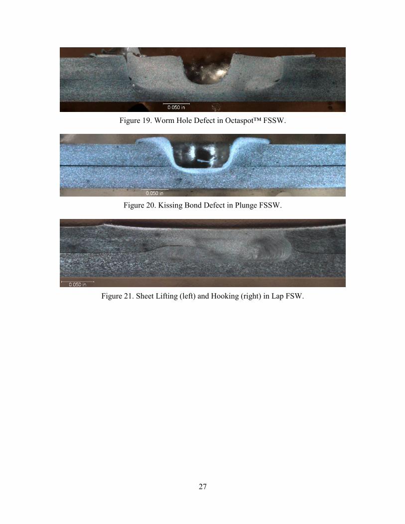
joint interface defects. Weld defects, such as lack of consolidation or lack of fill, which looks
like wormholes (Figure 19), and kissing bonds, known as lack of penetration into the second
sheet, leads to nugget shear failure (Figure 20). In a lap weld, sheet lifting is shown on the left
side of Figure 21, and hooking as shown on the right side of Figure 21, known as the upward or
downward movement of the joint interface, both hooking and sheet lifting create a sheet-thinning
defect on the upper or lower sheet of the welded coupon. Sheet thinning defects do appear in
Octaspot™ swept FSSW since it is a lap joint configuration, and changes of the loading path to a
thinner sheet leads to premature failure in mechanical testing. Optical metallographic digital
images and failure analysis of low Z-force Octaspot™ FSSW coupons on the tensile shear test
were categorized and documented.
27
Figure 19. Worm Hole Defect in Octaspot™ FSSW.
Figure 20. Kissing Bond Defect in Plunge FSSW.
Figure 21. Sheet Lifting (left) and Hooking (right) in Lap FSW.

28
CHAPTER 5
RESULTS AND DISCUSSIONS
5.1 Achieving Low Z-Force
Previous research has been performed using a 0.40-inch-diameter probe shoulder. This
data was beneficial in taking steps toward effective low Z-force FSSW. Octaspot™ swept FSSW
using the hybrid weld program consisted of position control in the plunge process and switching
to load control in the sweep stage. Feedback from the Z-force (forge force) of the position
control welds had two distinctive Z-force spikes, the probe spike and the shoulder spike, as the
material was in contact with the pin tool during the initial plunge, which reached up to 2,000 lbf
(1,100 lbf spike of Z-force in addition to 900 lbf command force (Figure 22)). The Z-force spike
can be as high as 1,500 lbf to 2,000 lbf in addition to the command Z-force. The high Z-force
spike created by the pin tool shoulder was undesirable for this low Z-force study because it is
beyond the force capability of most robotic arms.
FSW07079_01_9
0
500
1000
1500
2000
2500
347 348 349 350 351 352 353 354 355 356 357
Fo
rge F
orc
e (
lbf)
0
0.05
0.1
0.15
0.2
0.25
0.3
Forge Force Cmd, lbf Forge Force Fbk, lbf Forge Fbk, in
Plunge
Swept
Probe
Shoulder (Spike)
Fo
rge P
osit
ion
(in
)
Plunge
Swept
Probe
Shoulder (Spike)
Fo
rge P
osit
ion
(in
)
Figure 22. Command and Feedback Plot for Typical Octaspot™ FSSW
(Hybrid Weld Program).
Time (sec)

29
Therefore, a few possible solutions to reduce these spikes were considered: predrilling
before FSSW, preheating before FSSW, decreasing initial plunge depth, increasing spindle
speed, increasing dwell time, and decreasing plunge rate. Most of these possible solutions were
tested using the existing hybrid weld program, and the data from feedback forces was compared
directly with existing FSSW data. Predrilling and preheating before FSSW were not investigated
because the additional steps required for drilling and heating would increase the cycle time to
complete a spot weld. The remaining solutions were unsuccessful when implemented with the
existing hybrid weld program. Plunge depth was decreased from 0.005 inch to 0.001 inch, but Z-
force spike was not eliminated. Spindle speed increased up to 2,000 rpm created a hotter weld
and decreased the Z-force spike but was unable to eliminate it. Plunge rate decreased from 17
ipm to 1 ipm, which created a slower weld at the plunge stage and a distinctive probe spike and
shoulder spike. Dwell time increased from 1 second to 5 seconds before the swept stage tended
to reduce the Z-force spike. The Z-force spike was not eliminated, but trends of lower Z-force
spike were observed from the feedback forces plots. Therefore, the final option was to modify
the hybrid weld program to a load control weld program. Existing data of the 0.40-inch-diameter
shoulder weld using the hybrid weld program was used as a benchmark for Z-force and UTL
comparison.
A position-control weld program was used to determine an appropriate Z-force for a
corresponding hybrid weld program. The position-control weld program was also used to
estimate a required Z-force to maintain the tool depth while in the swept stage of the weld. The
0.40-inch-diameter shoulder created a spike up to 3,000 lbf, which decreased to an average of
1,700 lbf during the sweep stage of the FSSW (Figure 23), whereas the 0.30-inch-diameter
shoulder spiked up to 3,500 lbf and continuously dropped to an average of 800 lbf at the end of

30
the sweep stage (Figure 24). The reduction of Z-force at the end of the sweep stage for the 0.30-
inch-diameter shoulder showed that a lower Z-force could be achieved simply by reducing the
shoulder diameter. The data also suggest that all position control aspects of the weld program
should be eliminated and performed under load control in order to eliminate the Z-force spike in
Octaspot™ FSSW.
Using the estimated average load of 900 lbf from position control and applying it to the
load control weld program successfully produced Octaspot™ FSSW with a small Z-force spike.
The Z-force spike was lowered to 1,000 lbf; with command force of 900 lbf with additional
shoulder spike of 100 lbf (Figure 25).
0
0.05
0.1
0.15
0.2
0.25
0.3
0
500
1000
1500
2000
2500
3000
3500
197 199 201 203 205 207 209
Fo
rge
Fo
rce
(lb
f)
Time (sec)
CFSP08302_1_5
Forge Force Fbk, lbf Forge Fbk, in Forge Cmd, in
Fo
rge
Po
sit
ion
(in
)
3000 lbf
Average 1700 lbf
Figure 23. Command and Feedback Plot of 0.40-Inch-Diameter Psi™ Tool Welded with
Position Control.

31
0
0.05
0.1
0.15
0.2
0.25
0.3
0
500
1000
1500
2000
2500
3000
3500
4000
210 212 214 216 218 220 222
Fo
rge
Fo
rce
(lb
f)
Time (sec)
CFSP08301_1_5
Forge Force Fbk, lbf Forge Fbk, in Forge Cmd, in
Fo
rge
Po
sit
ion
(in
)
3500 lbf
800 lbf
Figure 24. Command and Feedback Plot of 0.30-Inch-Diameter Psi™ Tool Welded with
Position Control.
CFSP08301_11
0
200
400
600
800
1000
1200
53 55 57 59 61 63 65 67
Fo
rge
Fo
rce
(lb
f)
0
0.05
0.1
0.15
0.2
0.25
0.3
Forge Force Cmd, lbf Forge Force Fbk, lbf Forge Fbk, in
Fo
rge P
osit
ion
(in
)
Time (sec)
Shoulder (Spike)
Fo
rge P
osit
ion
(in
)
Time (sec)
Shoulder (Spike)
Figure 25. Command and Feedback Plot for Low Z-Force Swept FSSW.
The load-control weld program, known as the low Z-force weld program, successfully
created Octaspot™ FSSW with a low Z-force of 900 lbf, desirable joint interface, and a fully
consolidated weld nugget. The weld joint interface of low Z-force Octaspot™ FSSW is shown in

32
Figure 26, using a Psi™ tool with a 0.30-inch-diameter shoulder, and corresponds to the Z-force
feedback shown in Figure 25. The weld also exhibited a desirable joint interface with minimal or
no hooking, as shown in Figure 27.
Figure 26. Low Z-Force Cross-Sectional Metallographic (1.2X).
(a) (b) Figure 27. Joint Interface of Figure 26 (100X): (a) Left Side and (b) Right Side.
Using the same tool and lowering the commanded Z-force to 700 lbf, the command and
feedback force plot shows no spike of Z-force and only fluctuation of 50 lbf (Figure 28). The
load-control weld program significantly reduces the spike of Z-force, and a combination using a
low-commanded Z-force below 700 lbf can eliminate the Z-force spike. The surface faying
interface has minimal to no hooking for the swept FSSW welded with 700 lbf of commanded Z-
force.

33
CFSP08301_12
0
100
200
300
400
500
600
700
800
54 56 58 60 62 64 66 68Time (sec)
Fo
rge
Fo
rce
(lb
f)
0
0.05
0.1
0.15
0.2
0.25
0.3
Forge Force Cmd, lbf Forge Force Fbk, lbf Forge Fbk, in
Fo
rge
Po
sit
ion
(in
)
Figure 28. Command and Feedback Plot for Low Z-Force Swept FSSW. 5.2 Concave Shoulder Tool Study (Phase 1)
To further investigate strategies for reducing the Z-force, three essential process
parameters—Z-force, spindle speed, and travel speed—were studied in further detail while all
other parameters were held constant. Process parameters were investigated using Box-Behnken
DOE to show correlations between UTL and these three process parameters. The first DOE had a
process parameter low and high range of 4 ipm to 8 ipm for travel speed, 700 lbf to 1,100 lbf for
Z-force, and 800 rpm to 1,200 rpm for spindle speed with a midpoint (three levels). The UTL of
unguided single spot lap shear was used to correlate with the process parameters.
5.3 Concave Shoulder Diameter Study
In this part of the research, two pin tool designs were used to study the effects of shoulder
diameter on Z-force process parameter. Pin tool designs included Psi™ and Counterflow™ with
two five-degree concave shoulder diameter sizes of 0.30 inch and 0.40 inch.

34
5.3.1 Psi™ Tool (0.30 Inch and 0.40 Inch)
Low Z-force specimens were welded with two pin tool diameters, 0.30 inch and 0.40
inch, using a concave shoulder with a Psi™ tool probe. UTL increased for the 0.30-inch-
diameter shoulder specimens as the Z-force decreased (Figure 29). On the other hand, as the
UTL decreased, the Z-force decreased for the 0.40-inch-diameter shoulder (Figure 30).
UTL
UTL
Figure 29. Main Effects Plot of 0.30-Inch-Diameter Concave Shoulder Psi™ Tool.
UTL
UTL
Figure 30. Main Effects Plot of 0.40-Inch-Diameter Concave Shoulder Psi™ Tool.
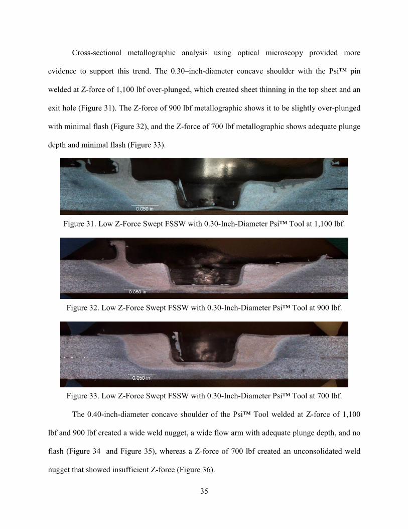
35
Cross-sectional metallographic analysis using optical microscopy provided more
evidence to support this trend. The 0.30–inch-diameter concave shoulder with the Psi™ pin
welded at Z-force of 1,100 lbf over-plunged, which created sheet thinning in the top sheet and an
exit hole (Figure 31). The Z-force of 900 lbf metallographic shows it to be slightly over-plunged
with minimal flash (Figure 32), and the Z-force of 700 lbf metallographic shows adequate plunge
depth and minimal flash (Figure 33).
Figure 31. Low Z-Force Swept FSSW with 0.30-Inch-Diameter Psi™ Tool at 1,100 lbf.
Figure 32. Low Z-Force Swept FSSW with 0.30-Inch-Diameter Psi™ Tool at 900 lbf.
Figure 33. Low Z-Force Swept FSSW with 0.30-Inch-Diameter Psi™ Tool at 700 lbf.
The 0.40-inch-diameter concave shoulder of the Psi™ Tool welded at Z-force of 1,100
lbf and 900 lbf created a wide weld nugget, a wide flow arm with adequate plunge depth, and no
flash (Figure 34 and Figure 35), whereas a Z-force of 700 lbf created an unconsolidated weld
nugget that showed insufficient Z-force (Figure 36).
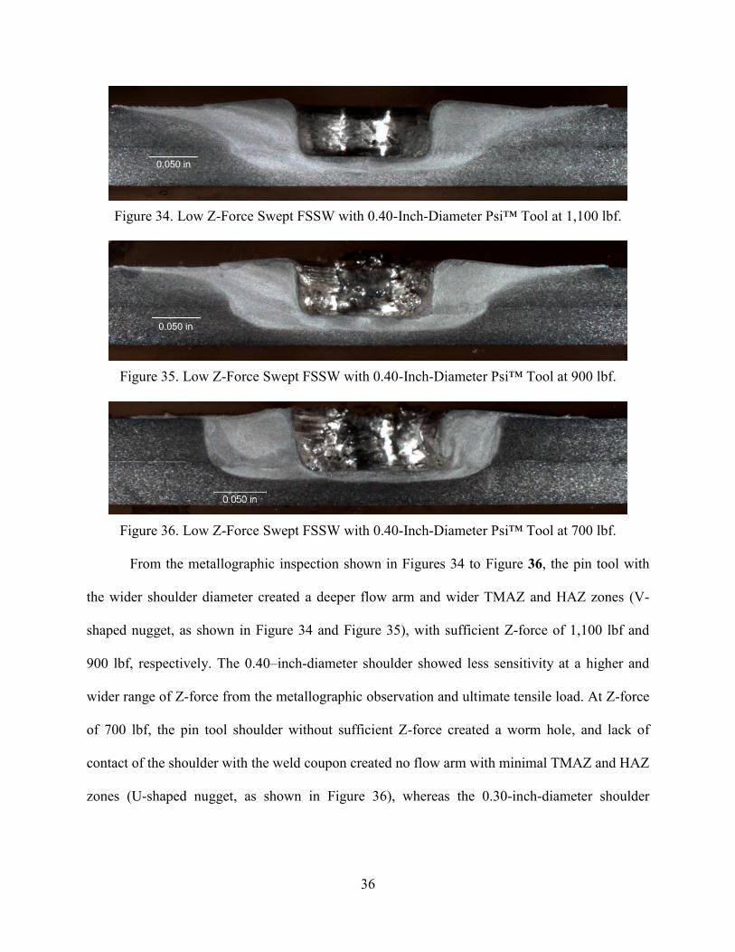
36
Figure 34. Low Z-Force Swept FSSW with 0.40-Inch-Diameter Psi™ Tool at 1,100 lbf.
Figure 35. Low Z-Force Swept FSSW with 0.40-Inch-Diameter Psi™ Tool at 900 lbf.
Figure 36. Low Z-Force Swept FSSW with 0.40-Inch-Diameter Psi™ Tool at 700 lbf.
From the metallographic inspection shown in Figures 34 to Figure 36, the pin tool with
the wider shoulder diameter created a deeper flow arm and wider TMAZ and HAZ zones (V-
shaped nugget, as shown in Figure 34 and Figure 35), with sufficient Z-force of 1,100 lbf and
900 lbf, respectively. The 0.40–inch-diameter shoulder showed less sensitivity at a higher and
wider range of Z-force from the metallographic observation and ultimate tensile load. At Z-force
of 700 lbf, the pin tool shoulder without sufficient Z-force created a worm hole, and lack of
contact of the shoulder with the weld coupon created no flow arm with minimal TMAZ and HAZ
zones (U-shaped nugget, as shown in Figure 36), whereas the 0.30-inch-diameter shoulder
0.050 in
0.050 in

37
showed higher sensitivity at a similar range of Z-force compared to the 0.40-inch-diameter
shoulder in metallographic observation and UTL.
Table 3 shows the results of average UTL for respective shoulder diameters and Z-forces,
which indicates that at a high Z-force of 1,100 lbf, the average UTL of the 0.30-inch-diameter
shoulder is low at 816 lbf, and at a low Z-force of 700 lbf, the average UTL of the 0.40-inch-
diameter shoulder is low at 1,050 lbf. Table 3 agrees with the main effect plots shown in Figure
29 and Figure 30.
TABLE 3
AVERAGE UTL AND CORRESPONDING Z-FORCES APPLIED USING CONCAVE SHOULDER PSI™ TOOL
Shoulder Diameter\
Average UTL Z-Forces Applied
700 lbf 900 lbf 1,100 lbf 0.30 inch 1,119 lbf 1,113 lbf 816 lbf 0.40 inch 1,050 lbf 1,192 lbf 1,216 lbf
Average UTL results refer to Appendix C 5.3.2 Counterflow™ Tool (0.30 Inch and 0.40 Inch)
Counterflow™ tool welded joints with two shoulder diameter sizes of 0.30 inch and 0.40
inch. The main effects plot shows a similar trend to the results of the Psi™ tool when welded
with similar weld parameters. The 0.30-inch-diameter concave shoulder shows better
performance at low Z-force compared to the 0.40-inch-diameter shoulder (Figure 37 and Figure
38).

38
UTLU
TL
Figure 37. Main Effects Plot of 0.30-Inch-Diameter Concave Shoulder Counterflow™ Tool.
UTL
UTL
Figure 38. Main Effects Plot of 0.40-Inch-Diameter Concave Shoulder Counterflow™ Tool.
Metallographic cross-sectional analysis of the 0.30-inch-diameter concave shoulder of the
Counterflow™ tool shows similar trends as that which occurred with the Psi™ tool. Figure 39
shows that over-plunging created sheet thinning at the exit hole, and the top sheet indicating
flash at Z-force of 1,100 lbf is similar to what is shown in Figure 31. Figure 40 shows slightly
over-plunging with minimal amount of flash at Z-force of 900 lbf, which is similar to what is
shown in Figure 32. Figure 41 shows a good weld nugget with adequate plunge at Z-force of 700
lbf, similar to what is shown in Figure 33.

39
Figure 39. Low Z-Force Swept FSSW with 0.30-Inch-Diameter Counterflow™ Tool
at 1,100 lbf.
Figure 40. Low Z-Force Swept FSSW with 0.30-Inch-Diameter Counterflow™ Tool
at 900 lbf.
Figure 41. Low Z-Force Swept FSSW with 0.30-Inch-Diameter Counterflow™ Tool
at 700 lbf.
Figure 42 and Figure 43 showing welds with a 0.40–inch-diameter concave shoulder with
the Counterflow™ tool at Z-force of 1,100 lbf and 900 lbf, respectively, show wider HAZ and
TMAZ zones (V-shaped nuggets), similar to what occurred with the 0.40–inch-diameter Psi™
tool. A 0.40-inch-diameter shoulder creates excessive heat and wider TMAZ and HAZ zones,
which changes the properties of the parent material and can significantly reduce overall strength
of the weld nugget.

40
Figure 42. Low Z-Force Swept FSSW with 0.40-Inch-Diameter Counterflow™ Tool
at 1,100 lbf.
Figure 43. Low Z-force Swept FSSW with 0.40-Inch-Diameter Counterflow™ Tool
at 900 lbf.
Table 4 shows the results of average UTL for respective shoulder diameters and Z-forces.
At a high Z-force of 1,100 lbf, the average UTL of a 0.30-inch-diameter shoulder is low at 1,013
lbf. At low Z-force of 700 lbf, the average UTL of a 0.40-inch-diameter shoulder is not available.
Table 4 agrees with the main effect plots shown in Figure 37 and Figure 38.
TABLE 4
AVERAGE UTL AND CORRESPONDING Z-FORCES APPLIED USING CONCAVE SHOULDER COUNTERFLOW™ TOOL
Shoulder Diameter\
Average UTL Z-Forces Applied
700 lbf 900 lbf 1,100 lbf 0.30 inch 1,165 lbf 1,184 lbf 1,013 lbf 0.40 inch NA 1,178 lbf 1,166 lbf
Average UTL results refer to Appendix C
The Counterflow™ tool with different shoulder diameters of 0.30 inch and 0.40 inch has
similar results and trends compared to the Psi™ tool. The 0.40–inch-diameter Counterflow™
tool was unable to plunge at 700 lbf Z-force because the tip of the probe has a larger surface area
0.050 in
0.050 in

41
compared to the Psi™ tool. The 0.30-inch-diameter shoulder pin tool for both the Psi™ tool and
Counterflow™ tool showed a better performance and achieved comparable UTL to the 0.40-
inch-diameter shoulder pin tool at lower Z-force using a low Z-force weld program. Since the
shoulder diameter investigation confirmed that the small shoulder can achieve lower Z-force, the
remaining pin tool design of the Modified Trivex™, Duo V-flute™, and Tri V-flute™, all with
0.40-inch-diameter shoulders was not investigated. Phase 2 of the study of shoulder features used
one tool selection based on phase 1 results with the 0.30-inch-diameter shoulder only. The
remaining phase 1 of this project was an investigation into different probe designs affecting the
Z-force and mechanical properties of swept FSSW using a 0.30-inch-diameter concave shoulder.
5.4 Probe Design Study with 0.30-Inch-Diameter Concave Shoulder
In the remainder of phase 1 (probe design study), the Modified Trivex™, Duo V-flute™,
and Tri V-flute™ pin tools with 0.30-inch-diameter concave shoulders were included in the
study and welded with the low Z-force weld program with similar weld parameters as the Psi™
and Counterflow™ tools. The different probe designs affected the nugget joint area and joint
interface morphology, both of which significantly affect UTL.
5.4.1 Modified Trivex™ Tool
The Modified Trivex™ tool welded joints with similar weld parameters had a
significantly lower average UTL of 911 lbf in the first DOE. The weld nugget metallographic
inspection at 1.2X magnification (Figure 46) was not enough to reveal hooking defects. At 100X
magnification, the surface faying interface was revealed (Figure 47), showing that a hooking
defect created sheet thinning on the upper sheet, which carried a significantly lower UTL. All
four metallographic cross-section specimens had hooking defects.

42
Besides metallographic analysis and UTL values, failure mode was another indication of
the hooking defect. All coupons tested in DOE 1 showed plug pull-out failure (Figure 48). The
Wankel’s triangular probe shape of the Modified Trivex™ tool promoted volumetric side
material movement due to the probe’s small physical to swept unit volume ratio. The triangular-
shaped probe tip area of the Modified Trivex™ was smaller compared to the circular-shaped
probe tip area of the Psi™ and Counterflow™ tools (Figure 14) (see Figure 9 and Table 1). This
finding led to an investigation of correlations of the probe’s physical to swept unit volume ratio
with different probe shapes to reduce volumetric side material movement. Volumetric side
material movement may promote hooking defects in a lap joint weld.
Metallographic analysis for DOE 1 shows that the 0.30-inch-diameter concave shoulder
over-plunged at 1,100 lbf Z-force creates excessive flash (Figure 44), slightly over-plunged at
900 lbf Z-force creates some flash (Figure 45), and an adequate plunge at 700 lbf Z-force (Figure
46). This trend is similar to that of Psi™ and Counterflow™ tools.
Figure 44. Low Z-Force Swept FSSW with 0.30-Inch-Diameter Modified Trivex™ Tool
at 1,100 lbf.

43
Figure 45. Low Z-Force Swept FSSW with 0.30-Inch-Diameter Modified Trivex™ Tool
at 900 lbf.
Figure 46. Low Z-Force Swept FSSW with 0.30-Inch-Diameter Modified Trivex™ Tool
at 700 lbf.
(a) (b) Figure 47. Joint Interface of Figure 46 (100X): (a) Right Side and (b) Left Side.
Figure 48. Plug Pull-Out Failure Mode.
0.250 in

44
5.4.2 Duo V-Flute™ Tool
The Duo V-flute™ tool welded joints with similar weld parameters as in first DOE had a
similar trend of weld nugget as that of the 0.30-inch-diameter Psi™, Counterflow™, and
Modified Trivex™ tools. Figure 49 metallographic shows that over-plunging at 1,100 lbf Z-force
created excessive flash, Figure 50 shows that slightly over-plunging at 900 lbf Z-force created
some flash, and Figure 51 shows adequate plunging at 700 lbf Z-force. Since the magnification
of 1.2X is not enough to reveal hooking defects, the 100X magnification of metallographic
analysis shown in Figure 52 indicates that no hooking occurred at the faying surface interface.
Figure 49. Low Z-Force Swept FSSW with 0.30-Inch-Diameter Duo V-Flute™ Tool
at 1,100 lbf.
Figure 50. Low Z-Force Swept FSSW with 0.30-Inch-Diameter Duo V-Flute™ Tool
at 900 lbf.
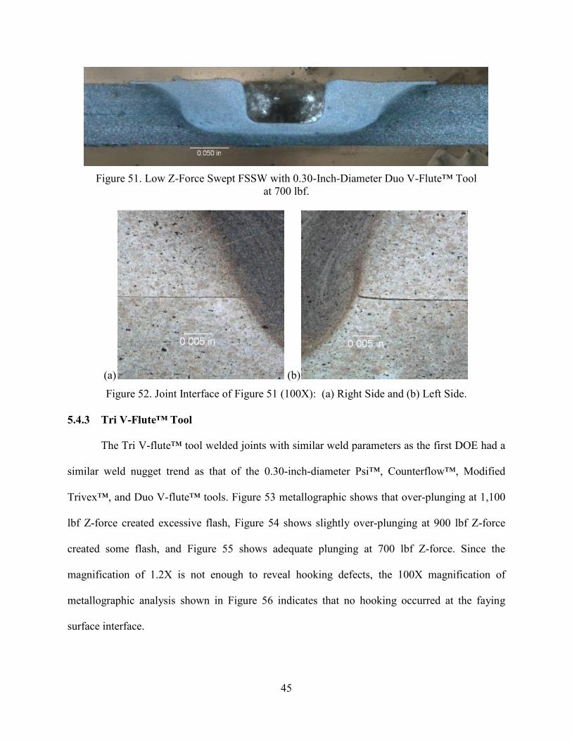
45
Figure 51. Low Z-Force Swept FSSW with 0.30-Inch-Diameter Duo V-Flute™ Tool
at 700 lbf.
(a) (b)
Figure 52. Joint Interface of Figure 51 (100X): (a) Right Side and (b) Left Side. 5.4.3 Tri V-Flute™ Tool
The Tri V-flute™ tool welded joints with similar weld parameters as the first DOE had a
similar weld nugget trend as that of the 0.30-inch-diameter Psi™, Counterflow™, Modified
Trivex™, and Duo V-flute™ tools. Figure 53 metallographic shows that over-plunging at 1,100
lbf Z-force created excessive flash, Figure 54 shows slightly over-plunging at 900 lbf Z-force
created some flash, and Figure 55 shows adequate plunging at 700 lbf Z-force. Since the
magnification of 1.2X is not enough to reveal hooking defects, the 100X magnification of
metallographic analysis shown in Figure 56 indicates that no hooking occurred at the faying
surface interface.

46
Figure 53. Low Z-Force Swept FSSW with 0.30-Inch-Diameter Tri V-flute™ Tool
at 1,100 lbf.
Figure 54. Low Z-Force Swept FSSW with 0.30-Inch-Diameter Tri V-flute™ Tool
at 900 lbf.
Figure 55. Low Z-Force Swept FSSW with 0.30-Inch-Diameter Tri V-flute™ Tool
at 700 lbf.
(a) (b)
Figure 56. Joint Interface of Figure 55 (100X): (a) Right Side and (b) Left Side.

47
5.5 Achievement in Concave Shoulder Study (Phase 1)
5.5.1 Concave Shoulder Diameter Study
Position control was found to be not suitable for low Z-force application on Octaspot™
swept FSSW due to the sudden increase in Z-force spikes. Using position control, the 0.30-inch-
diameter shoulder shows a promising decrease of Z-force at the end of Octaspot™ swept FSSW.
The weld program was modified to load control, and Z-force spikes were reduced significantly
and even eliminated. The 0.30-inch-diameter shoulder welded with the load-control weld
program performed better than the 0.40-inch-diameter shoulder at low Z-force. Although
performance of the 0.30-inch-diameter shoulder was better, sensitivity of the Z-force increased
significantly, thus affecting variation in plunge depth. The average UTL of low Z-force weld
coupons with a 0.30-inch-diameter shoulder were comparable with average UTL of high Z-force
spike weld coupons with a 0.40-inch-diameter shoulder. Since the 0.40-inch-diameter shoulder
requires higher Z-force, it was delineated from further study.
5.5.2 Probe Design Study
Using the same weld parameters as in the DOE 1 for five different probe designs showed
no significant increase of weld nugget area for Octaspot™ swept FSSW using the low Z-force
weld program (Figure 57 to Figure 61). Since the path and radius of Octaspot™ was similar, the
weld nugget size was similar across the five pin tool designs. The variation of weld nugget size
was due to different depths of polishing. Probe designs were analyzed for two main categories:
shape and features. The Modified Trivex™ has a Wankel’s triangular-shaped smaller probe tip
area compared to the other four pin tools that have a circular-shaped probe. The Psi™ tool with
three inclined flats slightly reduced the probe-tip area. A small probe-tip area is recommended to
further reduce the Z-force required for FSSW. Although a small probe-tip area reduced the

48
plunging Z-force, the small ratio of the probe’s physical to swept unit volume increased the
swept volume, which in turn promoted side material movement, thus creating the hooking defect.
Figure 57. Low Z-Force Swept FSSW with 0.30-Inch-Diameter Counterflow™ Tool
at 700 lbf.
Figure 58. Low Z-Force Swept FSSW with 0.30-Inch-Diameter Psi™ Tool
at 700 lbf.
Figure 59. Low Z-Force Swept FSSW with 0.30-Inch-Diameter Modified Trivex™ Tool
at 700 lbf.
Figure 60. Low Z-Force Swept FSSW with 0.30-Inch-Diameter Duo V-Flute™ Tool
at 700 lbf.

49
Figure 61. Low Z-Force Swept FSSW with 0.30-Inch-Diameter Tri V-Flute™ Tool
at 700 lbf.
Table 5 shows the first DOE UTL minimum, maximum, average, and standard deviation
values for five different probe designs. Figure 62 shows the average UTL with standard
deviation comparison between a 0.30-inch-diameter concave shoulder with five different probe
designs and high Z-force spike 0.40-inch-diameter benchmark UTL value. From the first DOE,
the average UTL of all tools was comparable to the average UTL of high Z-force, except the
Modified Trivex™ tool. Figure 62 shows no significant effect of the five probe designs to
variation in UTL of Octaspot™ FSSW due to a large standard deviation.
TABLE 5
COMPILATION OF DOE 1 UTL RESULTS FOR PROBE DESIGN STUDY OF 0.30-INCH-DIAMETER CONCAVE SHOULDER
Pin Tools\UTL Min Max Average Standard Deviation
Psi™ 624 lbf 1,208 lbf 1,036 lbf 163 lbf Counterflow™ 905 lbf 1,261 lbf 1,133 lbf 102 lbf Modified Trivex™ 785 lbf 1,036 lbf 911 lbf 61 lbf
Duo V-Flute™ 600 lbf 1,231 lbf 1,016 lbf 175 lbf Tri V-Flute™ 847 lbf 1,240 lbf 1,063 lbf 127 lbf UTL results refer to Appendix C

50
Low Z-force Swept FSSW 0.30 inch Shoulder Diameter
0
200
400
600
800
1000
1200
1400
DOE 1
Ult
imate
Ten
sile L
oad
(lb
f)
Psi
Counterflow
Trivex
Duo V-flute
Tri V-flute
High Z-force
Figure 62. UTL Results Comparison of Low Z-Force Octaspot™ Swept FSSW for
Five Pin Tools with 0.30-Inch-Diameter Concave Shoulder in DOE 1.
Since the first DOE was designed to accommodate the wide variation of probe designs
and shoulder diameters, optimization of the weld parameters was required to achieve higher and
precise UTL. Other factors include metallographic analysis to avoid over-plunging by reducing
the maximum Z-force from 1,100 lbf to 950 lbf and reduction in cycle time by increasing the
maximum travel speed from 8 ipm to 13 ipm. Statistical analysis of weld parameters also played
a minor role in weld parameter selection. The main effects plots of DOE 1 for all tools were
analyzed. The main effects plot shown in Figure 29 indicates that Z-force had a quadratic trend
line with a maximum point between 700 lbf and 1,100 lbf, travel speed had a quadratic trend line
with a minimum point between 4 ipm and 8 ipm, and spindle speed had a linear trend line with a
maximum point at 800 rpm and minimum point at 1,200 rpm. The main effects plot shown in
Figure 37 indicates that Z-force had a quadratic trend line with a maximum point between 700
lbf and 1,100 lbf, travel speed had a quadratic trend line with a minimum point at 4 ipm and
maximum point at 8 ipm, and spindle speed had a quadratic trend line with a maximum point
between 800 rpm and 1,200 rpm. From these two main effects plots, extrapolation of weld

51
parameters did not stand true but indicated that an increase in travel speed will further increase
UTL. Increase of travel speed is another factor that contributed to the reduction of cycle time of
welding. Weld program optimization also contributed to a reduction in weld cycle time, and
dwell time was reduced by an increase in acceleration rate of spindle rotational. Dwell time was
reduced from 7 seconds to 5 seconds and finally to 2 seconds by optimization of weld programs
(refer to Appendix B).
5.6 Optimization Weld Parameters (DOE 2)
The first DOE was created to find the process window, and the second DOE was created
to achieve maximum UTL for all tools. Using Box-Behnken DOE, weld parameters in both a
low and high range were selected, travel speed was 7 ipm to 13 ipm, Z-force was 750 lbf to 950
lbf, and spindle speed was 800 rpm to 1,100 rpm with a mid-point. The coupons were naturally
aged for a minimum of four days before tensile testing. The weld panels contained a total of 21
spot welds, with six coupons having repeated weld parameters for metallographic analysis.
In addition to optimizing the weld program, the weld cycle time was further reduced as a
result of optimizing the weld parameters in DOE 2. The low travel speed range (4-8 ipm) was
increased to a high travel speed range (7-13 ipm). This increase of travel speed reduced its weld
time significantly: an increase in travel speed from 4 ipm to 13 ipm reduced the weld time from
15 seconds to 7 seconds (refer to Appendix B). A total cycle time of five welds was analyzed and
compared and resulted in a total reduction of five seconds (refer to Appendix B). The fastest
Octspot™ swept FSSW was completed in a total time of nine seconds for each weld: two
seconds dwell time and seven seconds weld time.

52
Table 6 shows that the reduction of the standard deviation for all tools increases the
precision and repeatability of Octaspot™ FSSW by optimization through the response surface
method. Only the Psi™ tool had the highest standard deviation, almost double or triple compared
to the other tools. Hooking defects in all metallographics of the Modified Trivex™ tool
contributed to the low UTL values in DOE 2. The Wankel’s triangular-shaped Modified
Trivex™ tool with a small probe physical to swept unit volume ratio had a large side volumetric
displacement. Side volumetric displacement created the hooking defect in all welded coupons.
TABLE 6
COMPILATION OF DOE 2 UTL RESULTS FOR PROBE DESIGN STUDY OF 0.30-INCH-DIAMETER CONCAVE SHOULDER
Pin Tool\UTL Min Max Average Standard Deviation
Psi™ 731 lbf 1,234 lbf 1,143 lbf 129 lbf Counterflow™ 1,049 lbf 1,204 lbf 1,117 lbf 45 lbf Modified Trivex™ 874 lbf 1,024 lbf 958 lbf 44 lbf Duo V-Flute™ 976 lbf 1,255 lbf 1,176 lbf 76 lbf Tri V-Flute™ 1,021 lbf 1,245 lbf 1,173 lbf 63 lbf UTL results refer to Appendix C
Figure 63 shows that the Psi™ tool was able to match the average UTL of the
Counterflow™ tool on the second DOE with a slightly reduced standard deviation, whereas the
average UTL of the Counterflow™ tool dropped 16 lbf but the standard deviation was reduced
by half. The average UTL of the Duo V-flute™ and Tri V-flute™ increased, and the standard
deviation was reduced by half. The precision and repeatability of Octaspot™ swept FSSW
increased as the range of weld parameters decreased by optimization of the process parameters.
Metallographic cross-sections show minimal to no over-plunging, with minimal to no hooking
defects, except for the Modified Trivex™ tool.

53
Low Z-force Swept FSSW 0.30 inch Shoulder Diameter
0
200
400
600
800
1000
1200
1400
DOE 1 DOE 2
Ult
imate
Ten
sile L
oad
(lb
f)
Psi
Counterflow
Trivex
Duo V-flute
Tri V-flute
High Z-force
Figure 63. UTL Results Comparison of Low Z-Force Octaspot™ Swept FSSW for Five Pin Tools with 0.30-Inch-Diameter Concave Shoulder in DOE 1 and DOE 2.
Four tools showed the least significant effect of probe design to variation in UTL for
Octaspot™ swept FSSW, except the Modified Trivex™ tool. The radical probe shape of the
Modified Trivex™ tool with a small physical to swept unit volume ratio contributed to the
variation of UTL due to the hooking defect. However, features on the probe, such as vertical
flutes, inclined flats, threads, and opposing inclined flutes, contributed minimally to the variation
of UTL in both DOEs. The features on the probes, such as threads, flutes, and flats, had a
minimal effect on the tensile load due to the identical closed-loop path achieving closer values of
the tensile load results. Features such as inclined flutes are preferred, due to the clean shear on
the advancing side and minimal or no hooking at the joint interface. In Octaspot™ swept FSSW,
the shape of the probe with the small ratio of physical to swept unit volume may promote the
side displacement of material, which creates the hooking defect.

54
5.7 Surface Preparation
Surface oxide of the weld coupon at the joint interface and pin tool contact interface was
removed using a dual-action sander. Different operators removed a varied amount of surface
oxide, which may have contributed to the reduction of the weld quality. However, all pin tools,
except the Modified Trivex™, were welded with surface oxide remaining on the weld coupons.
MEK wipes remove dirt and oil without removing surface oxide.
Figure 64 shows that there was no reduction in average UTL, the amount of surface oxide
removed are not significant to the variation of UTL for Octaspot™ swept FSSW. The standard
deviation of UTL for all tools increased slightly except for the Psi™ tool, where the standard
deviation decreased. Therefore, reducing the surface preparation step in the manufacturing
process can significantly save time as well as the cost of labor and consumables without
sacrificing UTL.
Low Z-force Swept FSSW 0.30 inch Shoulder Diameter
0
200
400
600
800
1000
1200
1400
DOE 2 No Prep
Ult
imate
Te
nsil
e L
oa
d (
lbf) Psi
Counterflow
Trivex
Duo V-flute
Tri V-flute
High Z-force
Figure 64. UTL Results Comparison of Low Z-Force Octaspot™ Swept FSSW for Four Pin Tools with No Surface Preparation in DOE 2.
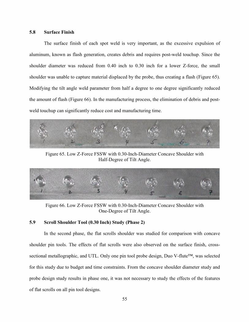
55
5.8 Surface Finish
The surface finish of each spot weld is very important, as the excessive expulsion of
aluminum, known as flash generation, creates debris and requires post-weld touchup. Since the
shoulder diameter was reduced from 0.40 inch to 0.30 inch for a lower Z-force, the small
shoulder was unable to capture material displaced by the probe, thus creating a flash (Figure 65).
Modifying the tilt angle weld parameter from half a degree to one degree significantly reduced
the amount of flash (Figure 66). In the manufacturing process, the elimination of debris and post-
weld touchup can significantly reduce cost and manufacturing time.
Figure 65. Low Z-Force FSSW with 0.30-Inch-Diameter Concave Shoulder with
Half-Degree of Tilt Angle.
Figure 66. Low Z-Force FSSW with 0.30-Inch-Diameter Concave Shoulder with
One-Degree of Tilt Angle. 5.9 Scroll Shoulder Tool (0.30 Inch) Study (Phase 2)
In the second phase, the flat scrolls shoulder was studied for comparison with concave
shoulder pin tools. The effects of flat scrolls were also observed on the surface finish, cross-
sectional metallographic, and UTL. Only one pin tool probe design, Duo V-flute™, was selected
for this study due to budget and time constraints. From the concave shoulder diameter study and
probe design study results in phase one, it was not necessary to study the effects of the features
of flat scrolls on all pin tool designs.

56
5.9.1 Achievement Duo V-Flute™ Scroll
Weld parameters used for the Duo V-flute™ Scroll pin tool were selected from a 0.30-
inch-diameter concave shoulder DOE 2, at 800 rpm to 1,100 rpm, 7 ipm to 13 ipm, and 750 lbf
to 950 lbf. Using the same weld parameters and probe features, the flat scrolls feature compared
fairly against the concave feature. The surface finish of Octaspot™ swept FSSW welds of flat
scrolls is not as smooth as the concave shoulder because the flat scrolls feature extends out of the
shoulder lip (Figure 67). The amount of flash generated using the flat scroll shoulder was less
compared to the concave shoulder welded with similar weld parameters (Figure 65). The flat
scrolls shoulder captured and directed material inward, generating a smaller amount of flash. The
concave shoulder tool required changing the tilt angle to one degree to reduce the amount of
flash generation (Figure 66), whereas the flat scrolls shoulder generated no flash with a half-
degree of tilt angle.
Figure 67. Low Z-Force FSSW with 0.30-Inch-Diameter Flat Scrolls Shoulder with
Half-Degree of Tilt Angle.
The average UTL of the Duo V-flute™ Scroll was 1,147 lbf, with a standard deviation of
50 lbf. The average UTL of the Duo V-flute™ Scroll was comparable to the Psi™,
Counterflow™, Duo V-flute™, and Tri V-flute™ concave shoulder tools. The standard deviation
of the flat scrolls shoulder was lower compared to the concave shoulder (Figure 68).

57
Low Z-force Swept FSSW 0.30 inch Diameter Shoulder
0
200
400
600
800
1000
1200
1400
DOE 2
Ult
imate
Ten
sil
e L
oad
(lb
f)
Psi
Counterflow
Trivex
Duo V-flute
Tri V-flute
High Z-force
Duo V-fluteScroll
Figure 68. UTL Results Comparison of Low Z-Force Octaspot™ Swept FSSW for
0.30-Inch-Diameter Scroll Shoulder Duo V-flute™ in DOE 2. The Z-force feedback plot shows no Z-force spike to a maximum spike of 100 lbf, in
addition to the commanded Z-force. The fluctuation of Z-force about 50 lbf was observed in all
15 welds. Metallographic analysis showed some degree of hooking at the surface interface up to
0.008 inch. The Duo V-flute™ with concave shoulder showed no sign of the hooking defect, but
the Duo V-flute™ with flat scrolls shoulder had hooking defects. The flat scrolls features might
promote a more aggressive flow arm directing material inward, thus creating hooking defects.
Recent discovery that the pin tool holder had worn out and because the pin tool had run out up to
0.010 inch might also be another cause for the hooking defect. Flat scroll features do not reduce
the Z-force compared to the concave shoulder with the same shoulder diameter.
5.10 Featureless Probe Shape Study (Phase 3)
The results of low average UTL coupled with metallographic analysis of the Modified
Trivex™ tool confirmed the hooking defect in all 15 welds of the DOE. The concave pin tool
study of different features on probe designs led to a study of probe shape, which showed that all
four pin tools with circular-shaped probe designs performed better than the triangular-shaped

58
Trivex™ pin tool. Therefore, a full parametric study of probe shape was initiated to investigate
the relationship of the probe physical to swept unit volume ratio and the hooking defect. It was
hypothesized that increasing the number of sides of the probe to make it closer to a circular
shape, or a ratio of probe physical to swept unit volume closer to 1, might reduce the hooking
defect (Figure 9 and Table 1). Due to budget and time constraints, three pin tools were selected
for this study: octagon, pentagon, and Trivex™ (Figure 15). The following weld parameters from
DOE 2 were utilized: 800 rpm to 1,100 rpm, 7 ipm to13 ipm, and 750 lbf to 950 lbf.
5.10.1 Featureless Trivex™
The Featureless Trivex™ pin tool achieved average UTL of 915 lbf with a standard
deviation of 50 lbf. The corresponding UTL and hooking defect ranged from 0.006 to 0.015 inch
for the respective metallographic cross-sectional shown in Table 7. UTL values do not directly
represent the severity of the hooking defect but more likely represent the set of process
parameters. Metallographic analysis showed a similar size of the weld nugget area, except for the
presence of the hooking defect (Figure 69, Figure 70, and Figure 71). Since these metallographic
cross–sectionals were taken using an inverted microscope, Figure 69 is flipped horizontally on
purpose to match the eye view through the microscope. Therefore, the left side of the Figure 69
metallographic image corresponds to the right side of the metallographic sample. The threaded
Trivex™ probe in the phase 1 design study showed that it achieved a similar average UTL of 958
lbf with a standard deviation of 44 lbf. Thus, the threaded features on the edge of the Trivex™
probe did not significantly enhance the UTL value.
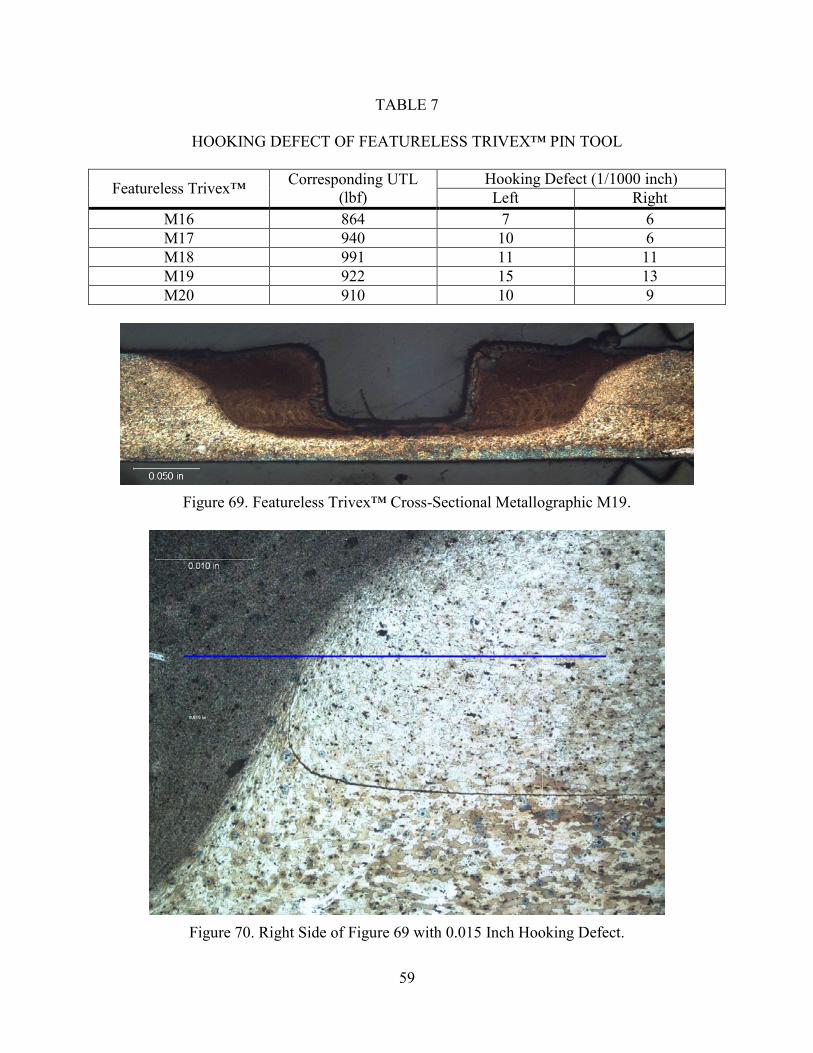
59
TABLE 7
HOOKING DEFECT OF FEATURELESS TRIVEX™ PIN TOOL
Featureless Trivex™ Corresponding UTL (lbf)
Hooking Defect (1/1000 inch) Left Right
M16 864 7 6 M17 940 10 6 M18 991 11 11 M19 922 15 13 M20 910 10 9
Figure 69. Featureless Trivex™ Cross-Sectional Metallographic M19.
Figure 70. Right Side of Figure 69 with 0.015 Inch Hooking Defect.

60
Figure 71. Left Side of Figure 69 with 0.013 Inch Hooking Defect.

61
5.10.2 Featureless Pentagon™
The Featureless Pentagon™ pin tool achieved an average UTL of 1,093 lbf with a
standard deviation of 66 lbf. The corresponding UTL and hooking defect ranged from 0 inch to
0.006 inch for the respective metallographic cross-sectional shown in Table 8. As with the
Trivex™ pin tool, severity of the hooking defect did not represent the UTL trend and depended
on the set of process parameters. Metallographic analysis showed the presence of the hooking
defect, but this was less severe than with the Trivex™-shaped pin tool (Figure 72, Figure 73, and
Figure 74). These metallographic images were taken using an inverted microscope; therefore, the
left side of Figure 72 corresponds to the right side of the metallographic sample.
TABLE 8
HOOKING DEFECT OF FEATURELESS PENTAGON™ PIN TOOL
Featureless Pentagon™ Corresponding UTL (lbf)
Hooking Defect (1/1000 inch) Left Right
M16 988 2 0 M17 1,038 6 2 M18 1,072 2 2 M19 1,119 5 2 M20 1,134 4 1
Figure 72. Featureless Pentagon™ Cross-Sectional Metallographic M19.

62
Figure 73. Right Side of Figure 72 with 0.005 Inch Hooking Defect.
Figure 74. Left Side of Figure 72 with 0.002 Inch Hooking Defect.

63
5.10.3 Featureless Octagon™
The Featureless Octagon™ pin tool achieved an average UTL of 1,033 lbf with a
standard deviation of 23 lbf. The corresponding UTL and hooking defect ranged from 0.002 to
0.009 inch for the respective metallographic in the cross-sectional shown in Table 9. UTL values
do not directly represent the severity of the hooking defect but are more representative of the set
of process parameters. Metallographic analysis showed a similar size of weld nugget area, except
for the presence of the hooking defect (Figure 75, Figure 76, and Figure 77). Since these
metallographic images were also taken with an inverted microscope, the right side of the image
is the left side of the metallographic sample.
TABLE 9
HOOKING DEFECT OF FEATURELESS OCTAGON™ PIN TOOL
Featureless Pentagon™ Corresponding UTL (lbf)
Hooking Defect (1/1000 inch) Left Right
M16 1028 5 2 M17 1029 5 2 M18 1066 6 6 M19 1015 9 8 M20 1012 8 5
Figure 75. Featureless Octagon™ Cross-Sectional Metallographic M19.

64
Figure 76. Right Side of Figure 75 with 0.009 Inch Hooking Defect.
Figure 77. Left Side of Figure 75 with 0.008 Inch Hooking Defect.

65
5.11 Achievement in Featureless Probe Shape Study (Phase 3)
Table 10 shows the trend and summary of the hooking defect and its relationship to the
ratio of probe physical to swept unit volume. The hooking defect values were recorded from five
metallographic samples within the DOE weld parameters range. The hooking defect was
averaged from four circular probes: Counterflow™, Psi™, Duo V-flute™, and Tri V-flute™. All
hooking defect images were taken with an inverted microscope and measured using PaxIt™
image software. The depth of samples in a mount may vary, and the different amount of grinding
and polishing of different mounted samples can affect the measurement of the hooking defect.
Therefore, a direct comparison of the hooking defect across different pin-tool metallographic
samples becomes less accurate, and metallographic samples within the same pin tool but
mounted in different setting cups will skew the hooking defect values. The hooking defect was
recorded in a two-dimensional or one cross-sectional segment. All metallographic samples were
polished as close to the center of the spot weld or slightly passed the center. In this study,
metallographic analysis found that the hooking defect could be three-dimensional, which may
vary around the weld nugget.
TABLE 10
SUMMARY OF HOOKING DEFECT AND RATIO OF PROBE PHYSICAL TO SWEPT UNIT VOLUME
Probe Shape UTL +/- Standard Deviation (lbf)
Ratio of Probe Physical to Swept
Unit Volume
Hooking Defect (1/1000 inch)
Circular with Features ~ 1,150 +/-78 1.000 ~0-5 Featureless Octagon™ 1,033 +/-23 0.891 2-9 Featureless Pentagon™ 1,093 +/-66 0.764 0-6 Featureless Trivex™ 915 +/-50 0.414 6-15 Threaded Trivex™ 958 +/-44 0.414 3-15 UTL results refer to Appendix C

66
The hypothesis of reducing the hooking defect by increasing the ratio of probe physical to
swept unit volume turned out to be false for this particular DOE set. Increasing the ratio of probe
physical to swept unit volume was similar to increasing the number of sides from triangular,
pentagon, and octagon, and did not show any trend supporting this hypothesis. However, the
hypothesis is still plausible because from the Trivex™-shaped tool to the Pentagon-shaped tool,
the hooking defect was reduced. Therefore, a full parametric investigation should be able to
confirm this hypothesis. Hooking defects can be reduced or eliminated by features on the probe,
such as the flutes, threads, flats, or combinations of more than one feature with the proper set of
process parameters. Locations of features on the probe are also crucial to eliminating the hooking
defect because threads at the edge of the Trivex™ pin tool did not reduce the hooking defect. A
combination of features is also important because the probe with threads alone creates sheet
thinning, but with additional features, the Counterflow flute reduces sheet thinning in the linear
lap weld.
5.12 Probe Diameter Study (Phase 4)
In phase 1, the concave shoulder pin tool study, a probe with a 0.135-inch diameter was
unable to plunge at certain weld parameters of low Z-force of 700 lbf, low spindle speed of 800
rpm, and high travel speed of 13 ipm. Probe designs with a small probe tip area, such as the
Psi™ tool with three inclined flats and the Trivex™ tool with a triangular-shaped probe were
able to plunge at the lower extremes of the set of weld parameters mentioned previously.
Therefore, a reduction of probe diameter from 0.135 inch to 0.100 inch will further reduce the
required Z-force to plunge below 700 lbf. During the design step of reducing probe diameter
size, it was determined that shoulder diameter could be reduced from 0.30 inch to 0.25 inch

67
(Figure 16c). This pin tool with the Duo V-flute™ probe was designed to reduce the Z-force
below 700 lbf.
Although the pin tool was designed to achieve a lower Z-force, another main objective of
this study was to maintain static UTL of 1,100 lbf. In Octaspot™, the spot radius was held
constant with the same probe diameter, but the total weld radius had to be increased to
compensate for the smaller probe diameter (Table 11). Increasing the spot radius to 0.100 inch
with a 0.050-inch probe radius created a total weld radius of 0.150 inch, slightly higher than the
current probe’s total weld radius of 0.148 inch.
TABLE 11
WELD RADIUS COMPENSATION FOR PROBE RADIUS REDUCTION
Pin Tool Probe Probe Radius Spot Radius Total Weld Radius Current Probe 0.068 inch 0.080 inch 0.148 inch Small Probe 0.050 inch 0.080 inch 0.130 inch Small Probe 0.050 inch 0.100 inch 0.150 inch
Since this study used a new pin tool, new weld parameters range were selected to achieve
a lower Z-force with a higher spindle speed range of 1300 rpm to 2000 rpm, travel speed range
of 7 ipm to 13 ipm, and Z-force range of 450 lbf to 700 lbf. In addition to investigating spindle
speed, travel speed, and Z-force weld parameters, tilt angle and spot radius were included.
Earlier investigations in phase 1 showed that an increase in the tilt angle improved the surface
finish for a shoulder-diameter modification from 0.4 inch to 0.3 inch. The weld spot radius was
increased to compensate for the decrease of probe radius to remain comparable to the weld
radius to achieve a UTL of 1,100 lbf.
The average UTL results shown in Table 12 consist of a work order from CFSP09307_4,
5, and 6, with weld parameters of 1,300 rpm to 2,000 rpm, 7 ipm to 13 ipm, and 450 lbf to 700
lbf and optimization in work order CFSP09307_7 with weld parameters of 1,500 rpm to 1,800

68
rpm, 8 ipm to 12 ipm, and 500 lbf to 600 lbf. The average UTL with wide standard deviation was
unable to provide significant results to confirm that the increase of tilt and spot radius increased
the average UTL. Metallographic results provided additional information to explain the slightly
lower average UTL and wide standard deviation.
TABLE 12
AVERAGE UTL AND STANDARD DEVIATION OF DOE 1 FOR PROBE DIAMETER STUDY
Work Order Average UTL (lbf) Standard Deviation
(lbf) Tilt, Spot Radius
(degree, inch) CFSP09307_4 813 291 0.5, 0.08 CFSP09307_5 872 300 0.5, 0.10 CFSP09307_6 909 245 1.0, 0.10 CFSP09307_7 1,025 149 1.0, 0.10
UTL results refer to Appendix C
One metallographic image (Figure 78) showed that a high spindle speed of 1,650 rpm
with a combination of slow travel speed of 7 ipm and high Z-force of 700 lbf caused the tool to
over plunge and the sheet to thin. Another metallographic image (Figure 79) showed that at a
low spindle speed of 1,300 rpm with a mid-travel speed of 10 ipm and low Z-force of 450 lbf, it
was not possible create a consolidated weld nugget. An unconsolidated weld is one of the main
reasons for a low average UTL and wide standard deviation. Good process parameters at a
spindle speed of 1,650 rpm, travel speed of 10 ipm, and Z-force of 575 lbf corresponded to a
good metallographic image that showed no significant defects (Figure 80) with a high UTL value
of 1,114 lbf. Metallographic images with obvious defects, shown in Figure 81, correspond to a
spindle speed of 2,000 rpm, travel speed of 13 ipm, and Z-force of 575 lbf, which yielded a UTL
of 662 lbf. Obvious defects due to an improper combination of weld parameters was another
contribution to lower average UTL and wide standard deviation. Metallographic images with

69
microdefects, which can only be detected at higher magnification with slightly reduced UTL to
1,000 lbf, were more difficult to analyze.
Figure 78. Metallographic Image of CFSP09307_6_M21.
Figure 79. Metallographic Image of CFSP09307_6_M17.
Figure 80. Metallographic Image of CFSP09307_6_M19.
Figure 81. Metallographic Image of CFSP09307_6_M23.
Although this DOE consists of weld parameters that can achieve a low Z-force of about
575 lbf with a high spindle speed up to 2,000 rpm, metallographic analysis showed defects, a
surface oxide line defect, and a confirmed lower UTL value. Since the FSSW process is highly

70
dependent on the amount of heat input, spindle speed and travel speed can significantly affect the
amount of Z-force that should be applied to obtain a sound FSSW. The concave shoulder
diameter study in phase 1 revealed that shoulder diameter is another factor affecting the amount
of Z-force required to produce a sound FSSW using the same weld parameters. Therefore, a
second DOE was initiated with a lower spindle speed range of 800 rpm to 1,100 rpm, travel
speed range of 7 ipm to 13 ipm, and Z-force range of 600 lbf to 800 lbf, similar to that used in
the concave shoulder diameter study DOE except for the Z-force. UTL results showed that the Z-
force at 600 lbf and a combination of low spindle speed of 800 rpm or 950 rpm and travel speed
of 10 ipm or 13 ipm, respectively, were unable to produce a sound FSSW and was confirmed
with a metallographic image that looks similar to Figure 79. In the DOE 2, weld parameters in
combination with a Z-force of 700 lbf produced FSSW with a UTL above 1,000 lbf up to 1,100
lbf. Results showed that reduction of the shoulder diameter from 0.3 inch to 0.25 inch did not
significantly reduce the amount of Z-force to produce a sound FSSW.
Optimization of the weld parameters by changing the Z-force range from 650 lbf to 750
lbf with a similar spindle speed and travel speed range yielded an average UTL of 1,091 lbf with
a standard deviation of 45 lbf. Reduction of the shoulder diameter can increase the sensitivity of
weld parameters: a Z-force range of at least 300 lbf for a 0.3-inch-diameter shoulder was reduced
to 100 lbf for a 0.25-inch-diameter shoulder. The amount of heat input through frictional heat of
the shoulder and probe can also affect the Z-force. A pin tool with a 0.1-inch-diameter probe
with a 0.25-inch-diameter shoulder produced less frictional heat than a 0.135-inch-diameter
probe with a 0.3-inch-diameter shoulder, which can increase the Z-force required to produce a
sound FSSW. An optimum shoulder diameter can reduce sensitivity of weld parameters, lower
the Z-force, and produce a sound FSSW.

71
In the DOE 2, the metallographic image in Figure 82 confirmed its respective UTL value
of 1,111 lbf showing no sign of defects. However, at high magnification, the metallographic
image in Figure 83 provided further details, which the UTL results were unable to detect, such as
microdefects and a surface oxide line. These are defects that cannot be detected by static shear
testing because the defects are protected by the weld nugget, which is strengthen by fine,
dynamically recrystallized grains. Some metallographic images from both DOEs showed some
microdefects and surface oxide lines in the weld nugget. These microdefects and surface oxide
lines can be a source of crack initiation, which can be detrimental in fatigue tests. Further
investigation will be required to eliminate voids, and surface oxide line defects using more
aggressive probe flute depths, and inadequate overlap of the probe radius and spot radius.
Figure 82. Metallographic Image of CFSP09307_12_M20.

72
Figure 83. Right Side of Nugget in Figure 82.
Although the Z-force was reduced by changing the weld parameter, pin tools have a
unique range of weld parameters, which dictate the Z-force range. Pin tools with different
shoulder and probe diameters and different probe designs with flutes, threads, flats, and shapes
can also contribute to and limit the range of weld parameters. The second DOE using a 0.25-
inch-diameter shoulder and 0.1-inch-diameter probe welded with a similar spindle speed and
travel speed of 0.30-inch-diameter shoulder and 0.135-inch-diameter probe achieved a reduction
of 150 lbf Z-force. The change from a 0.4-inch-diameter shoulder to a 0.3-inch-diameter
shoulder achieved a reduction of 250 lbf Z-force. The Counterflow™ tool reached the same UTL
value, regardless of shoulder size, with a similar Z-force.
Pin tools have unique weld parameters because 0.4-inch-diameter and 0.3-inch-diameter
shoulders have the same UTL with the same weld parameters, regardless of the difference in
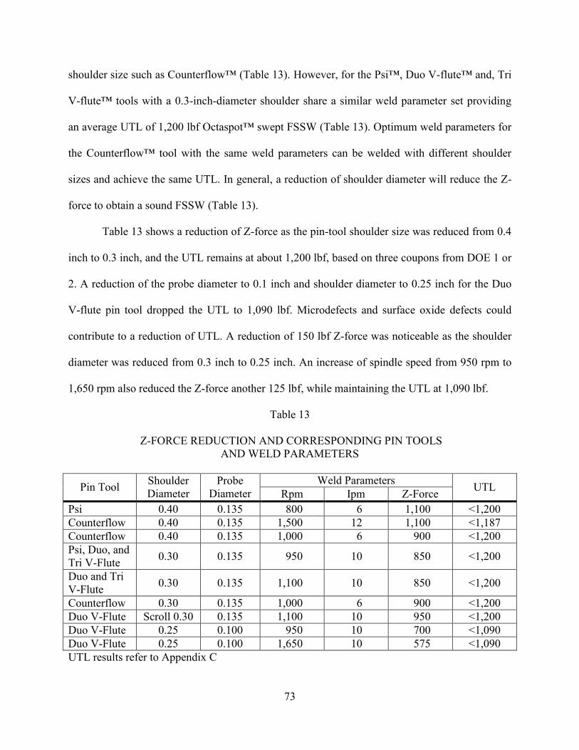
73
shoulder size such as Counterflow™ (Table 13). However, for the Psi™, Duo V-flute™ and, Tri
V-flute™ tools with a 0.3-inch-diameter shoulder share a similar weld parameter set providing
an average UTL of 1,200 lbf Octaspot™ swept FSSW (Table 13). Optimum weld parameters for
the Counterflow™ tool with the same weld parameters can be welded with different shoulder
sizes and achieve the same UTL. In general, a reduction of shoulder diameter will reduce the Z-
force to obtain a sound FSSW (Table 13).
Table 13 shows a reduction of Z-force as the pin-tool shoulder size was reduced from 0.4
inch to 0.3 inch, and the UTL remains at about 1,200 lbf, based on three coupons from DOE 1 or
2. A reduction of the probe diameter to 0.1 inch and shoulder diameter to 0.25 inch for the Duo
V-flute pin tool dropped the UTL to 1,090 lbf. Microdefects and surface oxide defects could
contribute to a reduction of UTL. A reduction of 150 lbf Z-force was noticeable as the shoulder
diameter was reduced from 0.3 inch to 0.25 inch. An increase of spindle speed from 950 rpm to
1,650 rpm also reduced the Z-force another 125 lbf, while maintaining the UTL at 1,090 lbf.
Table 13
Z-FORCE REDUCTION AND CORRESPONDING PIN TOOLS AND WELD PARAMETERS
Pin Tool Shoulder Diameter
Probe Diameter
Weld Parameters UTL Rpm Ipm Z-Force Psi 0.40 0.135 800 6 1,100 <1,200 Counterflow 0.40 0.135 1,500 12 1,100 <1,187 Counterflow 0.40 0.135 1,000 6 900 <1,200 Psi, Duo, and Tri V-Flute 0.30 0.135 950 10 850 <1,200
Duo and Tri V-Flute 0.30 0.135 1,100 10 850 <1,200
Counterflow 0.30 0.135 1,000 6 900 <1,200 Duo V-Flute Scroll 0.30 0.135 1,100 10 950 <1,200 Duo V-Flute 0.25 0.100 950 10 700 <1,090 Duo V-Flute 0.25 0.100 1,650 10 575 <1,090 UTL results refer to Appendix C
74
CHAPTER 6
CONCLUSIONS AND FUTURE WORK
The results of this study show that programmable load control enables low Z-force
FSSW. Conversely, a position-controlled weld program’s feedback forces cannot be controlled
to produce low Z-force FSSW. This is due to the sudden increase in normal force (Z-force spike)
when the tool shoulder comes into contact with the material using position control. Different
possible solutions were tried independently with a hybrid weld program without success of
eliminating the Z-force spike. However, the solution using a load-controlled weld program
provided significant reduction in Z-force spike from 1,500 lbf to 300 lbf and maintained FSSW
quality. Furthermore, reduction of shoulder diameter significantly reduced the required Z-force
while simultaneously maintaining good mechanical properties of Octaspot™ FSSW. A 0.30-
inch-diameter shoulder requires 850 lbf Z-force and performs better than a 0.40-inch-diameter
shoulder that requires 1,100 lbf Z-force.
Four pin tool designs—Psi™, Counterflow™, Duo V-flute, and Tri V-flute—coupled
with a low Z-force weld program and appropriate process parameters created a sound Octaspot™
FSSW, except for the Modified Trivex™ pin tool. Mechanical properties of low Z-force
Octaspot™ FSSW were investigated using unguided single-spot lap shear. The average UTL
(1,117 lbf to 1,173 lbf) of low Z-force Octaspot™ swept FSSW was comparable to the average
UTL (1,210 lbf) of high Z-force Octaspot™ FSSW. Probe designs with smaller probe tip areas,
such as Psi™ and Modified Trivex™, required less Z-force to plunge. Therefore, an
investigation of small probe diameters of 0.1 inch with a 0.25-inch-diameter shoulder
successfully lowered the Z-force below 700 lbf.

75
Modified Trivex™ pin tools that created weld coupons with a hooking defect were
excluded from the analysis of probe features. The initial hypothesis suggested that a probe design
such as the Modified Trivex™ with a small ratio of probe physical to swept unit volume creates
hooking defects. A separate investigation of probe shape was initiated to correlate the hooking
defect with the probe physical to swept unit volume ratio. However, the featureless probe shape
investigation was unable to confirm that an increase of probe physical to swept unit volume ratio
will reduce hooking defects. However, a weld parameter set tends to produce an aggressive
hooking defect across three different probe shapes. Features on probes, such as flutes, can
eliminate the hooking defect effectively if designed properly.
Lap joints are more likely to have a hooking defect on the faying surface interface, which
will affect UTL because of sheet thinning. V-flute™ pin tools with features such as flutes
performed excellently, not creating a hooking defect in the Octaspot™ FSSW. The threaded pin
tool created a hooking defect if it was not coupled with Counterflow™ flutes. A reduction of
shoulder diameter and Z-force created a preferable weld nugget with smaller TMAZ and HAZ
regions. Metallographic images were correlated with process parameters and pin tool designs to
further justify sound FSSW.
UTL and metallographic images should not be the only measures for good Octaspot™
FSSW. Surface finish was another criterion for this research, since reduction of shoulder
diameter increased the sensitivity of the process parameters, specifically Z-force, which can
cause flash generation. Surface finish of the FSSW should be level and without flash generation,
which can be adjusted with tilt angle and Z-force. A flat scrolls shoulder design also significantly
reduced flash generation, compared to the concave shoulder, without adjustment of process
parameters. Aluminum with surface oxide was welded as is and did not affect the UTL for four
76
different pin tools, thus potentially reducing a step of surface oxide removal in the manufacturing
process. Another objective was to reduce the processing time of each Octaspot™ swept FSSW,
through optimization of process parameters, and weld program. Optimization of the weld
program by reducing the dwell time and increasing the rate of acceleration reduced the weld
cycle time by at least five seconds. Optimization of weld parameter such as travel speed coupled
with statistical analysis showed that at a high travel speed, the UTL of Octaspot™ FSSW was
not compromised and was able to further reduce the weld time to 7 seconds.
Statistical analysis software (Statgraphics®) was used to correlate the UTL of the lap
shear coupons with respective process parameters for optimization of UTL. Four pin-tool designs
showed the least significant effect on the average UTL for different probe features with similar
weld process parameters. However, the Trivex™ probe shape significantly affected the average
UTL due to the hooking defect for similar weld process parameters. The optimization of weld
parameters increased the average UTL and reduced standard deviation UTL to achieve higher
repeatability with a wide range of weld parameters. The performance of the new pin tool design,
V-flute™, was comparable to Psi™ and Counterflow™. Besides optimization of weld
parameters, a balanced pin tool with optimized geometries such as shoulder and probe diameters
can avoid an unnecessary increase of weld parameter sensitivity.
These low Z-force FSSW results indicate that it is possible to produce sound FSSW joints
within the Z-force capability range of a typical articulated robot. Since the automotive and
aerospace industries are moving toward automation to improve production rate and quality
control simultaneously, the investigation of low Z-force FSSW will accelerate and bridge the
implementation of FSSW for articulated robots in those industries. Standards and specifications
for low Z-force FSSW will also be important to generate reproducible design data, such as

77
mechanical properties for a design engineer handbook. Application-based research, such as
surface sealant and surface treatment in low Z-force FSSW, is also important. Future work
should investigate the transfer of low Z-force FSSW knowledge to robotic applications, the
further reduction of Z-force through high rotational speed FSSW, and the impact of low Z-force
FSSW on joints with sealants.

78
REFERENCES

79
REFERENCES
[1] Thomas, W.M., Nicholas, E.D., Needham, J.C., Murch, M.G., Templesmith, P., and
Dawes, C.J., G.B. Patent 9125978.8, December 1991. [2] Mishra, R.S., and Mahoney, M.W., ―Friction Stir Welding and Processing,‖ ASM
International, Material Park, Ohio, The Materials Information Society, March 2007 [3] Lathabai, S., Painter, M.J., Cantin, G.M.D., and Tyagi, V.K., ―Friction Stir Spot Welding
of Automotive Lightweight Alloys,‖ Trends in Welding Research, Proceedings of the 7th International Conference, May 16-20, 2005, Callaway Garden Resort, Pine Mountain, Georgia, USA, pp. 207-212.
[4] Pan, T., ―Friction Stir Spot Welding (FSSW) - A Literature Review, SAE 2007 World
Congress,‖ Welding & Joining & Fastening & Friction Stir Welding, SAE International, April 16-19, 2007, Detroit, Michigan.
[5] Benedyk, J.C., ―SAE Celebrate 100th Anniversary at SAE 2005: Recent Advancements
in Automotive Light Metals,‖ Part IV Friction Stir Welding and Spot Friction Stir
Welding of Aluminum, Light Metal Age, Vol. 64, March/April 2006, pp. 34-43. [6] Iwashita, T., et al, ―Methods and Apparatus for Joining,‖ US Patent 6601751 B2, August
5, 2003. [7] Addison, A.C., and Robelou, A.J., ―Friction Sir Spot Welding: Principal Parameters and
their Effects,‖ Proceedings of the Fifth International Conference on Friction Stir
Welding, Sept 14-16, 2004 (Metz, France), TWI. [8] Schilling, C., von Strombeck, A., dos Santos, J.F., and von Heesen, N., ―A Preliminary
Investigation on the Static Properties of Friction Stir Spot Welds,‖ Proceedings of 2nd
Symposium on Friction Stir Welding, May 26-28, 2000, Gothenburg, Sweeden. [9] von Strombeck, A., Schilling, C., and dos Santos, J.F., ―Robotic Friction Stir Welding-
Tool Technology and Applications,‖ Proceedings of 2nd
Symposium on Friction Stir
Welding, May 26-28, 2000, Gothenburg, Sweden. [10] Okamoto, K., Hunt, F., and Hirano, S., ―Friction Stir Welding of Magnesium for
Automotive Applications,‖ SAE Technical Paper 2005-01-0730, SAE 2005 World Congress, April 11-14, 2005, Detroit, MI, USA.
[11] Okamoto, K., Hunt, F., and Hirano, S., ―Development of Friction Stir Welding Technique
and Machine for Aluminum Sheet Metal Assembly—Friction Stir Welding of Aluminum for Automotive Applications (2),‖ SAE Technical Paper 2005-01-1254, SAE 2005 World Congress, April 11-14, 2005, Detroit, MI, USA.

80
[12] Hunt, F., Badarinarayan, H., and Okamoto, K., ―Design of Experiments for Friction Stir
Stitch Welding of Aluminum Alloy 6022-T4—Friction Stir Welding of Aluminum for Automotive Applications (3),‖ SAE Technical Paper 2006-01-0970, SAE 2006 World Congress, April 3-6, 2006, Detroit, MI, USA.
[13] Kumagai, M., and Tanaka, S., ―Method of Spot Joining for Aluminum Alloy,‖ Japan
Patent 2001-259863, September 25, 2001. [14] Santella, M.L., Engstrom, T., Storjohann, D., and Pan, T., ―Effects of Friction Stir
Processing on Mechanical Properties of Cast Aluminum Alloy A356‖, SAE Paper 2005-01-1249.
[15] Ding, R.J., and Oelgoetz, P.A., ―Autoadjustable Pin Tool for Friction Stir Welding,‖ U.S.
Patent 5893507, April 13, 1999. [16] Skinner, M., and Edwards, R.L., ―Improvements to the FSW Process Using Self Reacting
Technology,‖ Proceedings of the 4th
International Friction Stir Welding Symposium, Vol. 426-432, pp. 2849-2854, Park City, Utah, May 2003.
[17] Marie, F., Allehaux, D., and Esmiller, B., ―Development of the Bobbin Tool Technique
on Various Aluminum Alloys,‖ Proceedings of the Fifth International Conference on
Friction Stir Welding, Sept 14-16, 2004 (Metz, France), TWI. [18] Pan, T., Jaoquin, A., Wilkosz, D.E., Reatherford, L., Nicholson, J.M., Feng, Z., and
Santella, M.L., ―Spot Friction Welding for Sheet Aluminum Joining,‖ Proceedings of the
Fifth International Conference on Friction Stir Welding, Sept 14-16, 2004, Metz, France, TWI.
[19] Montgomery, D.C., Design and Analysis of Experiments, 5th Edition, John Wiley & Sons
Inc., Hoboken, NJ, 2001. [20] Arbegast, W.J., ―Friction Stir Welding: After a Decade of Development,‖ Friction Stir
Welding and Processing IV, The Minerals, Metals & Material Society (TMS), Orlando, Florida, Feb 25- March 1, 12007.
[21] Burford, D., Tweedy, B., and Widener, C., ―Influence of Shoulder Configuration and
Geometric Features on FSW Track Properties,‖ Proceedings of the Sixth International
Symposium on Friction Stir Welding, TWI, 2006 Saint-Sauveur, Nr. Montreal, Canada, October 10-13.
[22] Kallee, S.W., and Mistry, A., ―Friction Stir Welding in the Automotive Body in White
Production,‖ Proceedings of the 1st International Conference on Friction Stir Welding, California, USA 1999.

81
[23] Allen, C.D., and Arbegast, W.J., ―Evaluation of Friction Spot Welds in Aluminum
Alloys,‖ Proceedings of the Spring 2005 SAE World Congress, Detroit, MI, 2005. [24] Shilling, C., and dos Santos, J.F., ―Method and Device for Joining at Least Two
Adjoining Work Pieces by Friction Welding,‖ US Patent App. 2002/0179 682. [25] Merry, J., Tweedy, B., Widener, C., and Burford, D. ―Static Strength Comparison of
Discontinuous Friction Stir Welded Stiffened Panels,‖ 7th AIAA Aviation Technology, Integration and Operations Conference (ATIO), Belfast, Northen Ireland, September 18-20, 2007.
[26] Tweedy, B., Widener, C., Merry, J., Brown, J., and Burford, D., ―Factors Affecting the
Properties of Swept Friction Stir Spot Welds,‖ SAE International, SAE 2008 World Congress, Detroit, MI, 2008.
[27] Burford, D., Tweedy, B., and Widener, C., ―Fatigue Crack Growth in Integrally Stiffened
Panels Joined Using Friction Stir Welding and Swept Friction Stir Spot Welding,‖ Journal of ASTM International, Vol. 5, No. 4, Paper ID JAI101568.
[28] Tweedy, B., Widener, C., Lam, T.J., Brown, J., and Burford, D. ―Fatigue of Swept
Friction Stir Spot Welds in thin Sheet 2024-T3 Aluminum,‖ SAE 2008 Aerospace Manufacturing & Automated Fastening Conference & Exhibition (AMAF), Charleston, SC, September 16-18, 2008.
[29] Merry, J., et al., ―Performance Evaluation of Discontinuous Friction Stir Welds,‖ SAE
2008 Wichita Aviation Technology Conference & Exhibition (WATC), Wichita, KS, August 19-21, 2008.
[30] Lam, T.J., ―Low Z-force Friction Stir Spot Welding- Conventional Tool & Process
Development Approach,‖ SAE 2008 Wichita Aviation Technology Conference & Exhibition (WATC), Wichita, KS, August 19-21, 2008.
[31] Lam, T.J., Widener, C., Brown, J., Tweedy, B., and Burford, D., ―Low Z-force Friction
Stir Spot Welding—Conventional Tool & Process Development Approach,‖ Friction Stir Welding and Processing V, The Minerals, Metals & Materials Society (TMS), San Francisco, CA, February 15-19, 2009.
[32] Brown, J., Burford, D., Widener, C., Tweedy, B., Horn, W., and Talia, G., ―Evaluation of
Friction Stir Spot Welding Through Sealants and Surface Treatments,‖ SAE 2008 Wichita Aviation Technology Conference & Exhibition (WATC), Wichita, KS, August 19-21, 2008.

82
[33] Tweedy, B., Widener, C., and Burford, D., ―The Effect of Surface Treatments on the
Faying Surface of Friction Stir Spot Welds,‖ Friction Stir Welding and Processing IV, The Minerals, Metals, & Materials Society (TMS), Orlando, Florida, Feb 25-March 1, 2007.
[34] J.E. Hatch, Ed., ―Aluminum Properties and Physical Metallurgy,‖ American Society for
Metals, Metals Park, OH, May 1984, pp. 175-177.

83
APPENDICES
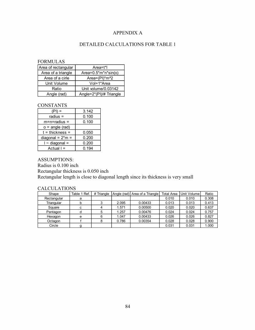
84
APPENDIX A
DETAILED CALCULATIONS FOR TABLE 1
FORMULAS Area of rectangular
Area of a triangleArea of a cirleUnit Volume
RatioAngle (rad)
Unit volume/0.03142Angle=2*(PI)/# Triangle
Area=0.5*m*n*sin(o)Area=(PI)*m 2̂
Area=t*l
Vol=1*Area
CONSTANTS
(PI) = 3.142radius = 0.100
m=n=radius = 0.100o = angle (rad)t = thickness = 0.050
diagonal = 2*m = 0.200l ~ diagonal = 0.200
Actual l = 0.194 ASSUMPTIONS: Radius is 0.100 inch Rectangular thickness is 0.050 inch Rectangular length is close to diagonal length since its thickness is very small CALCULATIONS
Shape Table 1 Ref. # Triangle Angle (rad) Area of a Triangle Total Area Unit Volume RatioRectangular a 0.010 0.010 0.308Triangular b 3 2.095 0.00433 0.013 0.013 0.413Square c 4 1.571 0.00500 0.020 0.020 0.637
Pentagon d 5 1.257 0.00476 0.024 0.024 0.757Hexagon e 6 1.047 0.00433 0.026 0.026 0.827Octagon f 8 0.786 0.00354 0.028 0.028 0.900
Circle g 0.031 0.031 1.000
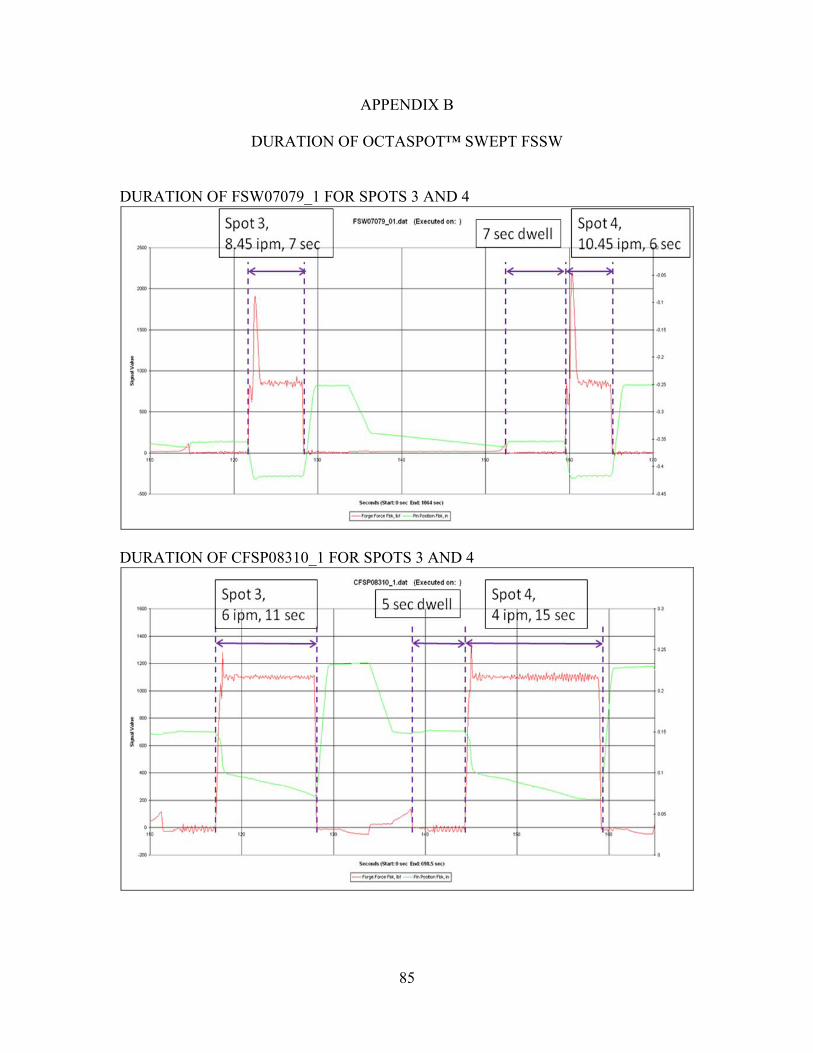
85
APPENDIX B
DURATION OF OCTASPOT™ SWEPT FSSW
DURATION OF FSW07079_1 FOR SPOTS 3 AND 4
DURATION OF CFSP08310_1 FOR SPOTS 3 AND 4
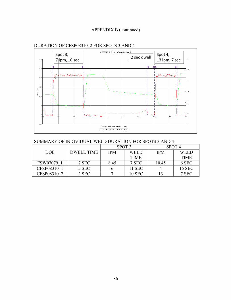
86
APPENDIX B (continued)
DURATION OF CFSP08310_2 FOR SPOTS 3 AND 4
Spot 3,7 ipm, 10 sec
Spot 4,13 ipm, 7 sec
2 sec dwell
SUMMARY OF INDIVIDUAL WELD DURATION FOR SPOTS 3 AND 4
DOE DWELL TIME SPOT 3 SPOT 4
IPM WELD TIME
IPM WELD TIME
FSW07079_1 7 SEC 8.45 7 SEC 10.45 6 SEC CFSP08310_1 5 SEC 6 11 SEC 4 15 SEC CFSP08310_2 2 SEC 7 10 SEC 13 7 SEC

87
APPENDIX B (continued)
DURATION OF CFSP08310_2 FOR 5 SPOTS
CFSP08310_2.dat
-200
0
200
400
600
800
1000
1200
100 120 140 160 180 200 220 240 260 280 300
Seconds
Sig
nal
Valu
e
0
0.05
0.1
0.15
0.2
0.25
0.3
Forge Force Cmd, lbf Forge Force Fbk, lbf Forge Fbk, in SUMMARY OF WELD DURATION FOR FIVE SPOTS
DOE Spot 3 to 8 (5spots) Cycle time for each spot
FSW07079_1 115 to 300 sec =185 sec (300-115)/5=37 secCFSP08310_1 111 to 286 sec = 175 sec (286-111)/5=35 secCFSP08310_2 121 to 281 sec = 160 sec (281-121)/5=32 sec

88
APPENDIX C
UTL RESULTS
0.3 INCH PSI™ TOOL DOE 1
Upper Shoulder PinLower Shoulder n/a Plate Thickness 0.040 Material 2024-T3
Weld Number Tensile # RPM IPM Pin Load (lbs)Ultimate
Tensile Load (lbs)
Avg UTL (ksi) St. Dev Failure Location
T01 800 8 900 1190 TOPT02 1000 6 900 1049 BOTTOMT03 800 6 1100 1005 TOPT04 1000 4 1100 747 TOPT05 800 6 700 1094 TOP/NUGGET SHEART06 1000 6 900 1138 BOTTOMT07 800 4 900 1143 BOTTOMT08 1200 6 700 1080 BOTTOMT09 1200 8 900 1135 TOPT10 1200 6 1100 624 TOPT11 1000 8 1100 889 TOPT12 1000 8 700 1095 BOTTOMT13 1200 4 900 1050 TOPT14 1000 4 700 1208 BOTTOMT15 1000 6 900 1087 BOTTOM
CFSP08301_14
CFSP08301 Advanced Joing Lab x520508-0055-0300-05-SN1
1035.5 163.2
Psi Tool Room 110
0.3 INCH PSI™ TOOL DOE 2
Room 110Upper Shoulder Pin Date July 22 2008Lower Shoulder n/a Plate Thickness 0.040 Material 2024-T3
Weld Number Tensile # RPM IPM Pin Load (lbs)Ultimate
Tensile Load (lbs)
Avg UTL (ksi) St. Dev Failure Location
T01 950 13 750 1023 Top & Bottom(Nugget Pullout)T02 950 13 950 1220 BottomT03 1100 7 850 1223 BottomT04 800 13 850 1126 BottomT05 800 10 950 1215 TopT06 800 10 750 731 Top & Bottom(Nugget Pullout)T07 1100 13 850 1181 B/Nugget PulloutT08 950 7 950 1091 BottomT09 950 7 750 1156 BottomT10 950 10 850 1234 Top & Bottom(Nugget Pullout)T11 950 10 850 1220 BottomT12 800 7 850 1193 TopT13 1100 10 950 1204 TopT14 950 10 850 1213 TopT15 1100 10 750 1113 Bottom
128.8
Psi ToolAdvanced Joing Lab x5205
CFSP08301_19
CFSP0830108-0055-0300-05-SN1
1142.8

89
APPENDIX C (continued)
0.4 INCH PSI™ TOOL DOE 1
Upper Shoulder PinLower Shoulder n/a Plate Thickness 0.040 Material 2024-T3
Weld Number Tensile # RPM IPM Pin Load (lbs)Ultimate
Tensile Load (lbs)
Avg UTL (ksi) St. Dev Failure Location
T01 800 8 900 1187 Top/Nugget ShearT02 1000 6 900 1154 BottomT03 800 6 1100 1219 BottomT04 1000 4 1100 1172 BottomT05 800 6 700 951 Nugget ShearT06 1000 6 900 1165 BottomT07 800 4 900 1250 Nugget ShearT08 1200 6 700 1129 BottomT09 1200 8 900 1191 BottomT10 1200 6 1100 1229 BottomT11 1000 8 1100 1243 BottomT12 1000 8 700 997 Top/Nugget ShearT13 1200 4 900 1210 BottomT14 1000 4 700 1124 BottomT15 1000 6 900 1189 Bottom
CFSP08302_3
CFSP08302 Advanced Joing Lab x520508-0055-0400-15 SN2
1160.7 84.9
Psi Tool Room 110
0.3 INCH COUNTERFLOW™ TOOL DOE 1
upper shoulder pinlower shoulder n/a plate thickness 0.040 Material 2024-T3
Weld Number Tensile # RPM IPM Pin Load (lbs)Ultimate
Tensile Load (lbs)
Avg UTL (ksi) St. Dev Failure Location
T01 800 8 900 1228 Top SheetT02 1000 6 900 1176 Top SheetT03 800 6 1100 1032 Top SheetT04 1000 4 1100 954 Top SheetT05 800 6 700 1138 Top SheetT06 1000 6 900 1208 Top SheetT07 800 4 900 1197 Top SheetT08 1200 6 700 1127 Top SheetT09 1200 8 900 1120 Top SheetT10 1200 6 1100 905 Top SheetT11 1000 8 1100 1159 Top SheetT12 1000 8 700 1234 Top SheetT13 1200 4 900 1100 Top SheetT14 1000 4 700 1161 Top SheetT15 1000 6 900 1261 Top Sheet
CFSP08304_03
CFSP08304 Advanced Joing Lab x520508-0055-0300-01-SN1
1133.3 101.5
Counterflow Tool Room 110

90
APPENDIX C (continued)
0.3 INCH COUNTERFLOW™ TOOL DOE 2
Room 110Upper Shoulder Pin Date July 22 2008Lower Shoulder n/a Plate Thickness 0.040 Material 2024-T3
Weld Number Tensile # RPM IPM Pin Load (lbs)Ultimate
Tensile Load (lbs)
Avg UTL (ksi) St. Dev Failure Location
T01 950 13 750 1126 TOPT02 950 13 950 1158 TOPT03 1100 7 850 1051 TOPT04 800 13 850 1204 TOPT05 800 10 950 1159 TOPT06 800 10 750 1108 TOPT07 1100 13 850 1122 TOPT08 950 7 950 1049 BOTTOMT09 950 7 750 1082 TOPT10 950 10 850 1151 TOPT11 950 10 850 1135 TOPT12 800 7 850 1134 TOPT13 1100 10 950 1059 TOPT14 950 10 850 1139 TOPT15 1100 10 750 1079 TOP
45.1
Counterflow ToolAdvanced Joing Lab x5205
CFSP08304_05
CFSP0830408-0055-0300-01-SN1
1117.1
0.4 INCH COUNTERFLOW™ TOOL DOE 1
Upper Shoulder PinLower Shoulder n/a Plate Thickness 0.040 Material 2024-T3
Weld Number Tensile # RPM IPM Pin Load (lbs)Ultimate
Tensile Load (lbs)
Avg UTL (ksi) St. Dev Failure Location
T01 800 8 900 1180 Nugget PulloutT02 1000 6 900 1307 TopT03 800 6 1100 1261 BottomT04 1000 4 1100 1139 TopT05 800 6 700 - -T06 1000 6 900 1311 BottomT07 800 4 900 1092 TopT08 1200 6 700 - -T09 1200 8 900 1130 TopT10 1200 6 1100 1066 TopT11 1000 8 1100 1199 TopT12 1000 8 700 - -T13 1200 4 900 1025 TopT14 1000 4 700 1119 Top/BottomT15 1000 6 900 1202 Bottom
CFSP08305_1
CFSP08305 Advanced Joing Lab x520508-0055-0400-11 SN1
1169.3 91.4
Counterflow Room 110

91
APPENDIX C (continued)
0.3 INCH TRIVEX™ TOOL DOE 1
Upper Shoulder PinLower Shoulder n/a Plate Thickness 0.040 Material 2024-T3
Weld Number Tensile # RPM IPM Pin Load (lbs)Ultimate
Tensile Load (lbs)
Avg UTL (ksi) St. Dev Failure Location
T01 800 8 900 1036 Top SheetT02 1000 6 900 970 Top SheetT03 800 6 1100 931 Top SheetT04 1000 4 1100 903 Top SheetT05 800 6 700 870 Top SheetT06 1000 6 900 925 Top SheetT07 800 4 900 947 Top SheetT08 1200 6 700 932 Top SheetT09 1200 8 900 885 Top SheetT10 1200 6 1100 850 Top SheetT11 1000 8 1100 785 Top SheetT12 1000 8 700 903 Top SheetT13 1200 4 900 842 Top SheetT14 1000 4 700 962 Top SheetT15 1000 6 900 930 Top Sheet
CFSP08308_1
CFSP08308 Advanced Joing Lab x520508-0055-0300-0-SN2
911.4 60.5
Trivex Tool Room 110
0.3 INCH TRIVEX™ TOOL DOE 2
Room 110Upper Shoulder Pin Date August 28 2008Lower Shoulder n/a Plate Thickness 0.040 Material 2024-T3
Weld Number Tensile # RPM IPM Pin Load (lbs)Ultimate
Tensile Load (lbs)
Avg UTL (ksi) St. Dev Failure Location
T01 950 13 750 936 Top SheetT02 950 13 950 952 Top SheetT03 1100 7 850 936 Top SheetT04 800 13 850 1008 Top SheetT05 800 10 950 1006 Top SheetT06 800 10 750 955 Top SheetT07 1100 13 850 967 Top SheetT08 950 7 950 874 Top SheetT09 950 7 750 943 Top SheetT10 950 10 850 971 Top SheetT11 950 10 850 993 Top SheetT12 800 7 850 1024 Top SheetT13 1100 10 950 877 Top SheetT14 950 10 850 987 Top SheetT15 1100 10 750 940 Top Sheet
43.7
Trivex ToolAdvanced Joing Lab x5205
CFSP08308_2
CFSP0830808-0055-0300-03-SN2
957.8
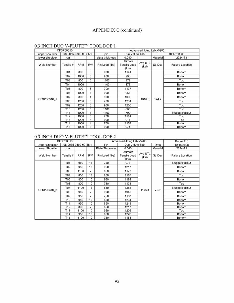
92
APPENDIX C (continued)
0.3 INCH DUO V-FLUTE™ TOOL DOE 1
upper shoulder pinlower shoulder n/a plate thickness 0.040 Material 2024-T3
Weld Number Tensile # RPM IPM Pin Load (lbs)Ultimate
Tensile Load (lbs)
Avg UTL (ksi) St. Dev Failure Location
T01 800 8 900 1141 BottomT02 1000 6 900 998 BottomT03 800 6 1100 979 TopT04 1000 4 1100 876 BottomT05 800 6 700 1137 BottomT06 1000 6 900 966 BottomT07 800 4 900 1095 BottomT08 1200 6 700 1231 TopT09 1200 8 900 1206 TopT10 1200 6 1100 600 TopT11 1000 8 1100 790 Nugget PulloutT12 1000 8 700 1181 TopT13 1200 4 900 911 TopT14 1000 4 700 1159 BottomT15 1000 6 900 974 Bottom
CFSP08310_1
CFSP08310 Advanced Joing Lab x520508-0055-0300-09-SN1
1016.3 174.7
Duo V-flute Tool 10/17/2008
0.3 INCH DUO V-FLUTE™ TOOL DOE 2
Room 110Upper Shoulder Pin Date 10/18/2008Lower Shoulder n/a Plate Thickness 0.040 Material 2024-T3
Weld Number Tensile # RPM IPM Pin Load (lbs)Ultimate
Tensile Load (lbs)
Avg UTL (ksi) St. Dev Failure Location
T01 950 13 750 976 Nugget PulloutT02 950 13 950 1217 BottomT03 1100 7 850 1177 BottomT04 800 13 850 1187 TopT05 800 10 950 1168 BottomT06 800 10 750 1131 TopT07 1100 13 850 1255 Nugget PulloutT08 950 7 950 1043 BottomT09 950 7 750 1187 BottomT10 950 10 850 1231 BottomT11 950 10 850 1243 BottomT12 800 7 850 1217 BottomT13 1100 10 950 1205 TopT14 950 10 850 1228 BottomT15 1100 10 750 1181 Bottom
75.9
Duo V-flute ToolAdvanced Joing Lab x5205
CFSP08310_2
CFSP0831008-0055-0300-09-SN1
1176.4

93
APPENDIX C (continued)
0.3 INCH TRI V-FLUTE™ TOOL DOE 1
upper shoulder pinlower shoulder n/a plate thickness 0.040 Material 2024-T3
Weld Number Tensile # RPM IPM Pin Load (lbs)Ultimate
Tensile Load (lbs)
Avg UTL (ksi) St. Dev Failure Location
T01 800 8 900 1157 BottomT02 1000 6 900 1038 BottomT03 800 6 1100 1016 TopT04 1000 4 1100 892 Bottom/Nugget PulloutT05 800 6 700 1145 TopT06 1000 6 900 1057 BottomT07 800 4 900 1094 BottomT08 1200 6 700 1200 BottomT09 1200 8 900 1240 Nugget PulloutT10 1200 6 1100 847 TopT11 1000 8 1100 868 BottomT12 1000 8 700 1169 BottomT13 1200 4 900 970 Nugget PulloutT14 1000 4 700 1208 BottomT15 1000 6 900 1045 Bottom
CFSP08312_1
CFSP08312 Advanced Joing Lab x520508-0055-0300-07-SN1
1063.0 126.8
Tri V-flute Tool 10/18/2008
0.3 INCH TRI V-FLUTE™ TOOL DOE 2
Room 110Upper Shoulder Pin Date 10/18/2008Lower Shoulder n/a Plate Thickness 0.040 Material 2024-T3
Weld Number Tensile # RPM IPM Pin Load (lbs)Ultimate
Tensile Load (lbs)
Avg UTL (ksi) St. Dev Failure Location
T01 950 13 750 1155 TopT02 950 13 950 1194 BottomT03 1100 7 850 1145 BottomT04 800 13 850 1200 TopT05 800 10 950 1086 BottomT06 800 10 750 1156 TopT07 1100 13 850 1245 TopT08 950 7 950 1021 BottomT09 950 7 750 1201 BottomT10 950 10 850 1230 BottomT11 950 10 850 1237 BottomT12 800 7 850 1208 BottomT13 1100 10 950 1129 BottomT14 950 10 850 1243 BottomT15 1100 10 750 1151 Bottom
62.7
Tri V-flute ToolAdvanced Joing Lab x5205
CFSP08312_2
CFSP0831208-0055-0300-07-SN1
1173.3

94
APPENDIX C (continued)
0.3 INCH DUO V-FLUTE™ SCROLL TOOL DOE 2
Room 110Upper Shoulder Pin Date 4/29/2009Lower Shoulder n/a Plate Thickness 0.040 Material 2024-T3
Weld Number Tensile # RPM IPM Pin Load (lbs)Ultimate
Tensile Load (lbs)
Avg UTL (ksi) St. Dev Failure Location
T01 950 13 750 1102 TopT02 950 13 950 1103 TopT03 1100 7 850 1168 TopT04 800 13 850 1121 TopT05 800 10 950 1142 TopT06 800 10 750 1165 TopT07 1100 13 850 1141 TopT08 950 7 950 1171 TopT09 950 7 750 1116 TopT10 950 10 850 1121 TopT11 950 10 850 1106 TopT12 800 7 850 1147 TopT13 1100 10 950 1301 TopT14 950 10 850 1132 TopT15 1100 10 750 1172 Top
Duo V-flute Scrolls ToolAdvanced Joing Lab x5205
CFSP09303_1
CFSP0930309-0055-0300-10-SN1
1147.2 49.3
0.3 INCH FEATURELESS OCTAGON™ TOOL DOE 2
Room 110Upper Shoulder Pin Date 4/29/2009Lower Shoulder n/a Plate Thickness 0.040 Material 2024-T3
Weld Number Tensile # RPM IPM Pin Load (lbs)Ultimate
Tensile Load (lbs)
Avg UTL (ksi) St. Dev Failure Location
T01 950 13 750 1028 TopT02 950 13 950 1046 TopT03 1100 7 850 1029 TopT04 800 13 850 1040 TopT05 800 10 950 1066 TopT06 800 10 750 987 TopT07 1100 13 850 1015 TopT08 950 7 950 1038 TopT09 950 7 750 1012 TopT10 950 10 850 1039 TopT11 950 10 850 1047 TopT12 800 7 850 1068 TopT13 1100 10 950 1053 TopT14 950 10 850 1030 TopT15 1100 10 750 998 Top
Octagon ToolAdvanced Joing Lab x5205
CFSP09304_1
CFSP0930409-0055-0300-27-SN1
1033.2 23.0

95
APPENDIX C (continued)
0.3 INCH FEATURELESS PENTAGON™ TOOL DOE 2 Room 110
Upper Shoulder Pin Date 4/29/2009Lower Shoulder n/a Plate Thickness 0.040 Material 2024-T3
Weld Number Tensile # RPM IPM Pin Load (lbs)Ultimate
Tensile Load (lbs)
Avg UTL (ksi) St. Dev Failure Location
T01 950 13 750 988 TopT02 950 13 950 1021 TopT03 1100 7 850 1038 TopT04 800 13 850 1045 TopT05 800 10 950 1072 TopT06 800 10 750 1007 TopT07 1100 13 850 1119 TopT08 950 7 950 1137 TopT09 950 7 750 1134 TopT10 950 10 850 1097 TopT11 950 10 850 1094 TopT12 800 7 850 1115 TopT13 1100 10 950 1187 TopT14 950 10 850 1118 TopT15 1100 10 750 1221 Top
65.5
Pentagon ToolAdvanced Joing Lab x5205
CFSP09305_1
CFSP0930509-0055-0300-25-SN1
1092.8
0.3 INCH FEATURELESS TRIVEX™ TOOL DOE 2
Room 110Upper Shoulder Pin Date 4/29/2009Lower Shoulder n/a Plate Thickness 0.040 Material 2024-T3
Weld Number Tensile # RPM IPM Pin Load (lbs)Ultimate
Tensile Load (lbs)
Avg UTL (ksi) St. Dev Failure Location
T01 950 13 750 864 Top T02 950 13 950 954 Top T03 1100 7 850 940 Top T04 800 13 850 955 Top T05 800 10 950 991 Top T06 800 10 750 826 Top T07 1100 13 850 922 Top T08 950 7 950 906 Top T09 950 7 750 910 Top T10 950 10 850 924 Top T11 950 10 850 949 Top T12 800 7 850 963 Top T13 1100 10 950 840 Top T14 950 10 850 932 Top T15 1100 10 750 844 Top
49.8
Trivex ToolAdvanced Joing Lab x5205
CFSP09306_1
CFSP0930609-0055-0300-03-SN1
914.7

96
APPENDIX C (continued)
0.25 INCH DUO V-FLUTE™ TOOL WITH 0.1 INCH PROBE Room 110
Upper Shoulder Pin Date 4/30/2009Lower Shoulder n/a Plate Thickness 0.040 Material 2024-T3
Weld Number Tensile # RPM IPM Pin Load (lbs)Ultimate
Tensile Load (lbs)
Avg UTL (ksi) St. Dev Failure Location
T01 1650 13 700 1012 TopT02 2000 10 700 907 TopT03 1300 10 450 1 N/AT04 1650 7 450 562 Nugget ShearT05 2000 7 575 1003 TopT06 1300 13 575 967 TopT07 1650 10 575 1035 TopT08 1650 10 575 1035 TopT09 1650 10 575 1008 TopT10 1650 13 450 466 Nugget ShearT11 1650 7 700 889 BottomT12 2000 10 450 645 Nugget PulloutT13 1300 10 700 984 TopT14 1300 7 575 962 Top/ Nugget ShearT15 2000 13 575 721 Nugget Pullout
290.5
0.25 Duo V-flute 0.1 PinAdvanced Joing Lab x5205
CFSP09307_4
CFSP0930709-0055-0250-09-SN1
813.1
0.25 INCH DUO V-FLUTE™ TOOL WITH 0.1 INCH PROBE
Room 110Upper Shoulder Pin Date 4/30/2009Lower Shoulder n/a Plate Thickness 0.040 Material 2024-T3
Weld Number Tensile # RPM IPM Pin Load (lbs)Ultimate
Tensile Load (lbs)
Avg UTL (ksi) St. Dev Failure Location
T01 1650 13 700 1101 Nugget PulloutT02 2000 10 700 960 TopT03 1300 10 450 89 Nugget ShearT04 1650 7 450 693 TopT05 2000 7 575 1100 TopT06 1300 13 575 1035 TopT07 1650 10 575 1107 TopT08 1650 10 575 1118 TopT09 1650 10 575 1086 TopT10 1650 13 450 554 Nugget ShearT11 1650 7 700 932 Nugget PulloutT12 2000 10 450 635 TopT13 1300 10 700 1007 Bottom/Nugget PulloutT14 1300 7 575 1091 Nugget PulloutT15 2000 13 575 576 Nugget Pullout
300.0
0.25 Duo V-flute 0.1 PinAdvanced Joing Lab x5205
CFSP09307_5
CFSP0930709-0055-0250-09-SN1
872.2

97
APPENDIX C (continued)
0.25 INCH DUO V-FLUTE™ TOOL WITH 0.1 INCH PROBE
Room 110Upper Shoulder Pin Date 4/30/2009Lower Shoulder n/a Plate Thickness 0.040 Material 2024-T3
Weld Number Tensile # RPM IPM Pin Load (lbs)Ultimate
Tensile Load (lbs)
Avg UTL (ksi) St. Dev Failure Location
T01 1650 13 700 1058 Nugget Pull OutT02 2000 10 700 967 TopT03 1300 10 450 290 Nugget ShearT04 1650 7 450 750 TopT05 2000 7 575 1057 TopT06 1300 13 575 1055 TopT07 1650 10 575 1114 TopT08 1650 10 575 1094 TopT09 1650 10 575 1099 TopT10 1650 13 450 581 Nugget ShearT11 1650 7 700 950 BottomT12 2000 10 450 781 TopT13 1300 10 700 1096 BottomT14 1300 7 575 1076 TopT15 2000 13 575 662 Nugget Pull Out
244.8
0.25 Duo V-flute 0.1 PinAdvanced Joing Lab x5205
CFSP09307_6
CFSP0930709-0055-0250-09-SN1
908.6
0.25 INCH DUO V-FLUTE™ TOOL WITH 0.1 INCH PROBE
Room 110Upper Shoulder Pin Date 4/30/2009Lower Shoulder n/a Plate Thickness 0.040 Material 2024-T3
Weld Number Tensile # RPM IPM Pin Load (lbs)Ultimate
Tensile Load (lbs)
Avg UTL (ksi) St. Dev Failure Location
T01 1650 12 500 658 TopT02 1650 10 550 1058 TopT03 1500 10 600 1169 TopT04 1650 8 600 1139 TopT05 1650 8 500 999 TopT06 1800 8 550 1151 TopT07 1800 10 600 1071 TopT08 1650 10 550 1092 TopT09 1500 8 550 1098 TopT10 1800 10 500 1024 TopT11 1650 12 600 1078 TopT12 1500 12 550 1031 TopT13 1500 10 500 704 TopT14 1800 12 550 990 TopT15 1650 10 550 1105 Top
149.3
0.25 Duo V-flute 0.1 PinAdvanced Joing Lab x5205
CFSP09307_7
CFSP0930709-0055-0250-09-SN1
1024.5

98
APPENDIX C (continued)
0.25 INCH DUO V-FLUTE™ TOOL WITH 0.1 INCH PROBE
Room 110Upper Shoulder Pin Date 6/15/2009Lower Shoulder n/a Plate Thickness 0.040 Material 2024-T3
Weld Number Tensile # RPM IPM Pin Load (lbs)Ultimate
Tensile Load (lbs)
Avg UTL (ksi) St. Dev Failure Location
T01 950 10 700 1105.9 TOPT02 1100 7 700 1089.8 TOP/BOTTOMT03 1100 10 800 1014.2 BOTTOMT04 950 13 800 1118.9 TOP/ BOTTOMT05 950 7 800 1163.4 TOPT06 950 7 600 1041.1 TOPT07 950 10 700 1097.0 TOPT08 1100 13 700 1093.0 TOPT09 950 10 700 1103.8 TOPT10 800 7 700 1072.8 TOPT11 800 10 800 1111.4 TOPT12 950 13 600 765.9 TOP/BOTTOM/NUGGETT13 800 10 600 545.7 NUGGETT14 800 13 700 1017.9 TOP/BOTTOM/NUGGETT15 1100 10 600 1029.1 TOP
160.7
0.25 Duo V-flute 0.1 PinAdvanced Joing Lab x5205
CFSP09307_12
CFSP0930709-0055-0250-09-SN1
1024.7
0.25 INCH DUO V-FLUTE™ TOOL WITH 0.1 INCH PROBE
Room 110Upper Shoulder Pin Date 6/15/2009Lower Shoulder n/a Plate Thickness 0.040 Material 2024-T3
Weld Number Tensile # RPM IPM Pin Load (lbs)Ultimate
Tensile Load (lbs)
Avg UTL (ksi) St. Dev Failure Location
T01 1100 10 750 1122 TOP/BOTTOMT02 950 7 650 1085 TOPT03 800 10 750 1124 TOPT04 950 10 700 1119 TOPT05 1100 13 700 1085 TOPT06 1100 7 700 1086 TOP/BOTTOMT07 800 13 700 1090 TOPT08 950 13 750 1129 TOPT09 950 7 750 1145 BOTTOMT10 800 7 700 1113 TOPT11 800 10 650 959 TOP/NUGGETT12 1100 10 650 1065 TOPT13 950 13 650 1047 TOPT14 950 10 700 1098 TOPT15 950 10 700 1090 TOP
44.5
0.25 Duo V-flute 0.1 PinAdvanced Joing Lab x5205
CFSP09307_13
CFSP0930709-0055-0250-09-SN1
1090.5

99
APPENDIX C (continued)
0.3 INCH PSI™ TOOL DOE 2 (NO PREPARATION)
Room 110Upper Shoulder Pin Date Oct 29 2008Lower Shoulder n/a Plate Thickness 0.040 Material 2024-T3
Weld Number Tensile # RPM IPM Pin Load (lbs)Ultimate
Tensile Load (lbs)
Avg UTL (ksi) St. Dev Failure Location
T01 950 13 750 1063 Nugget PulloutT02 950 13 950 1231 Nugget PulloutT03 1100 7 850 1140 BottomT04 800 13 850 1171 TopT05 800 10 950 1253 BottomT06 800 10 750 1074 Nugget ShearT07 1100 13 850 1154 Nugget PulloutT08 950 7 950 1105 BottomT09 950 7 750 1226 BottomT10 950 10 850 1258 BottomT11 950 10 850 1268 BottomT12 800 7 850 1233 Nugget PulloutT13 1100 10 950 1164 TopT14 950 10 850 1174 Top &BottomT15 1100 10 750 1108 Bottom
68.0
Psi ToolAdvanced Joing Lab x5205
CFSP08301_20
CFSP0830108-0055-0300-05-SN1
1174.7
0.3 INCH COUNTERFLOW™ TOOL DOE 2 (NO PREPARATION)
Room 110Upper Shoulder Pin Date October 29 2008Lower Shoulder n/a Plate Thickness 0.040 Material 2024-T3
Weld Number Tensile # RPM IPM Pin Load (lbs)Ultimate
Tensile Load (lbs)
Avg UTL (ksi) St. Dev Failure Location
T01 950 13 750 1165 TopT02 950 13 950 1142 TopT03 1100 7 850 1037 TopT04 800 13 850 1222 TopT05 800 10 950 1197 TopT06 800 10 750 1222 TopT07 1100 13 850 1097 TopT08 950 7 950 1120 TopT09 950 7 750 1139 TopT10 950 10 850 1215 TopT11 950 10 850 1197 TopT12 800 7 850 1169 TopT13 1100 10 950 1036 TopT14 950 10 850 1154 TopT15 1100 10 750 1071 Top
62.8
Counterflow ToolAdvanced Joing Lab x5205
CFSP08304_06
CFSP0830408-0055-0300-01-SN1
1145.4

100
APPENDIX C (continued)
0.3 INCH DUO V-FLUTE™ TOOL DOE 2 (NO PREPARATION)
Room 110Upper Shoulder Pin Date 10/29/2008Lower Shoulder n/a Plate Thickness 0.040 Material 2024-T3
Weld Number Tensile # RPM IPM Pin Load (lbs)Ultimate
Tensile Load (lbs)
Avg UTL (ksi) St. Dev Failure Location
T01 950 13 750 1039 Nugget PulloutT02 950 13 950 1178 BottomT03 1100 7 850 1157 BottomT04 800 13 850 1162 TopT05 800 10 950 1170 BottomT06 800 10 750 959 Nugget PulloutT07 1100 13 850 1234 BottomT08 950 7 950 1040 BottomT09 950 7 750 1213 BottomT10 950 10 850 1235 BottomT11 950 10 850 1247 BottomT12 800 7 850 1217 BottomT13 1100 10 950 1216 TopT14 950 10 850 1232 BottomT15 1100 10 750 1152 Bottom
85.7
Duo V-flute ToolAdvanced Joing Lab x5205
CFSP08310_3
CFSP0831008-0055-0300-09-SN1
1163.3
0.3 INCH TRI V-FLUTE™ TOOL DOE 2 (NO PREPARATION)
Room 110Upper Shoulder Pin Date 10/29/2008Lower Shoulder n/a Plate Thickness 0.040 Material 2024-T3
Weld Number Tensile # RPM IPM Pin Load (lbs)Ultimate
Tensile Load (lbs)
Avg UTL (ksi) St. Dev Failure Location
T01 950 13 750 891 Nugget PulloutT02 950 13 950 1194 BottomT03 1100 7 850 1159 BottomT04 800 13 850 1193 TopT05 800 10 950 1189 BottomT06 800 10 750 1104 Nugget ShearT07 1100 13 850 1256 BottomT08 950 7 950 1029 BottomT09 950 7 750 1229 BottomT10 950 10 850 1263 BottomT11 950 10 850 1247 BottomT12 800 7 850 1233 BottomT13 1100 10 950 1185 TopT14 950 10 850 1258 BottomT15 1100 10 750 1152 Bottom
100.4
Tri V-flute ToolAdvanced Joing Lab x5205
CFSP08312_3
CFSP0831208-0055-0300-07-SN1
1172.3
Related Documents