Low voltage Motors for explosive atmospheres Catalog | February 2016

Welcome message from author
This document is posted to help you gain knowledge. Please leave a comment to let me know what you think about it! Share it to your friends and learn new things together.
Transcript
Low voltage Motors for explosive atmospheres
Catalog | February 2016

2 9AKK104006 EN 02-2016 | ABB Motors and Generators
With expertise, and a comprehensive portfolio of products and life-cycle services, we help value-minded industrial customers improve their energy efficiency and productivity.
Low voltage motors for explosive atmospheresSizes 71 to 450, 0.25 to 1000 kW
General information 04
Flameproof motors Ex d IIB/IIC T4 Gb 33
Flameproof motors Ex de IIB/IIC T4 Gb 67
Increased safety motors Ex e IIC T3 Gb 103
Non-sparking cast iron motors Ex nA IIC T3 Gc 137
Non-sparking aluminum motors Ex nA IIB/C T3 Gc 179
Dust ignition protection cast iron motors /
Protection by enclosure Ex t IIIB/ IIIC T125 °C Db/Dc 197
Dust ignition protection aluminum motors /
Protection by enclosure Ex t IIIB/ IIIC T125 °C Db/Dc 237
Total product offering 257
Life-cycle services and support 258
ABB Motors and Generators | 9AKK104006 EN 02-2016 3
General information
European ATEX DirectivesThe ATEX Directives harmonize safety rules in line with the free trading principles of the European Community.
Responsibilities are split between the manufacturers and end users. Manufacturers have to comply with the “Essential Health and Safety Requirements” of the Products Directive 94/9/EC and end users must prepare an Explosion Protection Document based on risk assessments of their “work places” and “work equipment” to fulfil the “minimum requirements” listed in the Worker Protection Directive 1999/92/EC. The new ATEX products directive 2014/34/EU dated 26th February 2014 will be applicable from the 20th April 2016, this directive replaces current Products directive 94/9/EC.
ABB low voltage motors for explosive atmospheres comply fully with the ATEX Products Directive.
According to the regulations, low voltage motors for explosive atmospheres are exempted from the Low Voltage Directive, the EMC Directive and the Machinery Directive.
IECEx SystemThe IECEx System is a certification system which verifies compliance with IEC (International Electrotechnical Commission) standards relating to safety in explosive atmospheres. It covers equipment, service facilities and the competency of personnel.
Created in September 1999, the System aims “to facilitate international trade in equipment and services for use in explosive atmospheres, while maintaining the required level of safety…” (source: IECEx website, www.iecex.com). It is a voluntary system which provides an internationally accepted means of proving that products and services are in compliance with IEC standards. The voluntary and international aspects of the IECEx System differentiate it from certification under ATEX, for example, which is mandatory but applies only within the European Economic Area.
The IECEx System comprises global certification programs for both equipment and service facilities.
IECEx certification involves – in addition to product tests – assessment of quality control procedures and testing plans, audits of manufacturing plants, and routine on-going surveillance and inspections.
In addition, IECEx has established a comprehensive set of operational documents and procedures to develop a single internationally standardized approach to Ex testing and certification.
The approach includes: − A standardized “IECEx way of Ex Testing and Certification”.
There is a single set of operational procedures, and Ex test procedures are always applied in the same way.
− A dedicated Technical and Operational Secretariat to maintain operations. Ex test procedures are evaluated and monitored on a centralized basis.
Who is responsible for the certification work?A manufacturer needing to have equipment certified under the IECEx System can apply to an IECEx Competent Body (ExCB) in any member country. At present there are more than 30 IECEx member countries. The ExCB performs or coordinates the activities of certification.
A quality assessment of the manufacturer is undertaken by the ExCB itself, and the auditor issues an IECEx Quality Assessment Report (QAR).
Type testing of product samples is performed on behalf of the ExCB by an IECEx Assessment and Testing Laboratory (ExTL). On completion of its work the ExTL’s assessment engineer prepares an IECEx Test Report (ExTR).
The ExTR is then submitted to the ExCB for endorsement. Based on the QAR and ExTR, the ExCB then issues the Certificate of Conformity (CoC). The CoC provides internationally accepted verification that the equipment in question is in compliance with the relevant IEC standards. Once formally issued by the ExCB, both the ExTR and QAR are registered on the IECEx Internet site. This provides verification that an ExTR and QAR exist for the product and manufacturer.
How do I know if a motor is IECEx certified?IECEx certified motors show the certification number on their rating plate, for example: “IECEx LCI 05.0008”. In this case “LCI” indicates that the IECEx certificate was issued by LCIE, an IECEx approved Certification Body in France.
M00
0167
M00
0701
4 9AKK104006 EN 06-2014 | ABB Motors and Generators
Which ABB motors and generators are IECEx certified?All M3JP/M3KP 80–450 motors with protection types Ex d and Ex de, M3GP 71-450 with protection type Ex nA and M3GP 71-450 with protection type Ex t are IECEx certified, together with a part of the M3AA range with Ex nA and Ex t protection.
Compliance on basis of recently updated standardsIn complying with the ATEX 95 directives, ABB follows the requirements of recently updated IEC and EN standards. Otherwise ABB follows the requirements of the IEC standards shown in the relevant certificates.
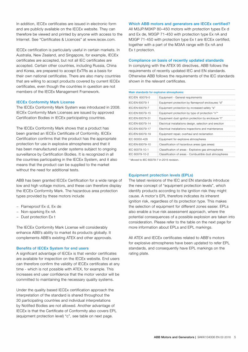
* Moved to IEC 60079-7 in 2015 revision.
Equipment protection levels (EPLs)The latest revisions of the IEC and EN standards introduce the new concept of “equipment protection levels”, which identify products according to the ignition risk they might cause. A motor's EPL therefore indicates its inherent ignition risk, regardless of its protection type. This makes the selection of equipment for different zones easier. EPLs also enable a true risk assessment approach, where the potential consequences of a possible explosion are taken into consideration. Please refer to the table on the next page for more information about EPLs and EPL markings.
All ATEX and IECEx certificates related to ABB's motors for explosive atmospheres have been updated to refer EPL standards, and consequently have EPL markings on the rating plate.
In addition, IECEx certificates are issued in electronic form and are publicly available on the IECEx website. They can therefore be viewed and printed by anyone with access to the Internet. See “Certificates & Licences” at www.iecex.com.
IECEx certification is particularly useful in certain markets. In Australia, New Zealand, and Singapore, for example, IECEx certificates are accepted, but not all IEC certificates are accepted. Certain other countries, including Russia, China and Korea, are prepared to accept ExTRs as a basis for their own national certificates. There are also many countries that are willing to accept products covered by current IECEx certificates, even though the countries in question are not members of the IECEx Management Framework.
IECEx Conformity Mark LicenseThe IECEx Conformity Mark System was introduced in 2008. IECEx Conformity Mark Licenses are issued by approved Certification Bodies in IECEx participating countries.
The IECEx Conformity Mark shows that a product has been granted an IECEx Certificate of Conformity. IECEx Certification confirms that the product has the appropriate protection for use in explosive atmospheres and that it has been manufactured under systems subject to ongoing surveillance by Certification Bodies. It is recognized in all the countries participating in the IECEx System, and it also means that the product can be supplied to the market without the need for additional tests.
ABB has been granted IECEx Certification for a wide range of low and high voltage motors, and these can therefore display the IECEx Conformity Mark. The hazardous area protection types provided by these motors include
− Flameproof Ex d, Ex de − Non-sparking Ex nA − Dust protection Ex t
The IECEx Conformity Mark License will considerably enhance ABB’s ability to market its products globally. It complements ABB’s existing ATEX and other approvals.
Benefits of IECEx System for end usersA significant advantage of IECEx is that vendor certificates are available for inspection on the IECEx website. End users can therefore confirm the validity of IECEx certificates at any time - which is not possible with ATEX, for example. This increases end user confidence that the motor vendor will be committed to maintaining the necessary quality systems.
Under the quality based IECEx certification approach the interpretation of the standard is shared throughout the 30 participating countries and individual interpretations by Notified Bodies are not allowed. Another advantage of IECEx is that the Certificate of Conformity also covers EPL (equipment protection level) “c”, see table on next page.
Main standards for explosive atmospheres:
IEC/EN 60079-0 Equipment - General requirements
IEC/EN 60079-1 Equipment protection by flameproof enclosures “d”
IEC/EN 60079-7 Equipment protection by increased safety “e”
IEC/EN 60079-15 Equipment protection by type of protection “n”*
IEC/EN 60079-31 Equipment dust ignition protection by enclosure “t”
IEC/EN 60079-14 Electrical installations design, selection and erection
IEC/EN 60079-17 Electrical installations inspections and maintenance
IEC/EN 60079-19 Equipment repair, overhaul and reclamation
IEC 60050-426 Equipment for explosive atmospheres
IEC/EN 60079-10 Classification of hazardous areas (gas areas)
IEC 60079-10-1 Classification of areas - Explosive gas atmospheres
IEC 60079-10-2 Classification of areas - Combustible dust atmospheres
ABB Motors and Generators | 9AKK104006 EN 02-2016 5
Explosive atmospheres
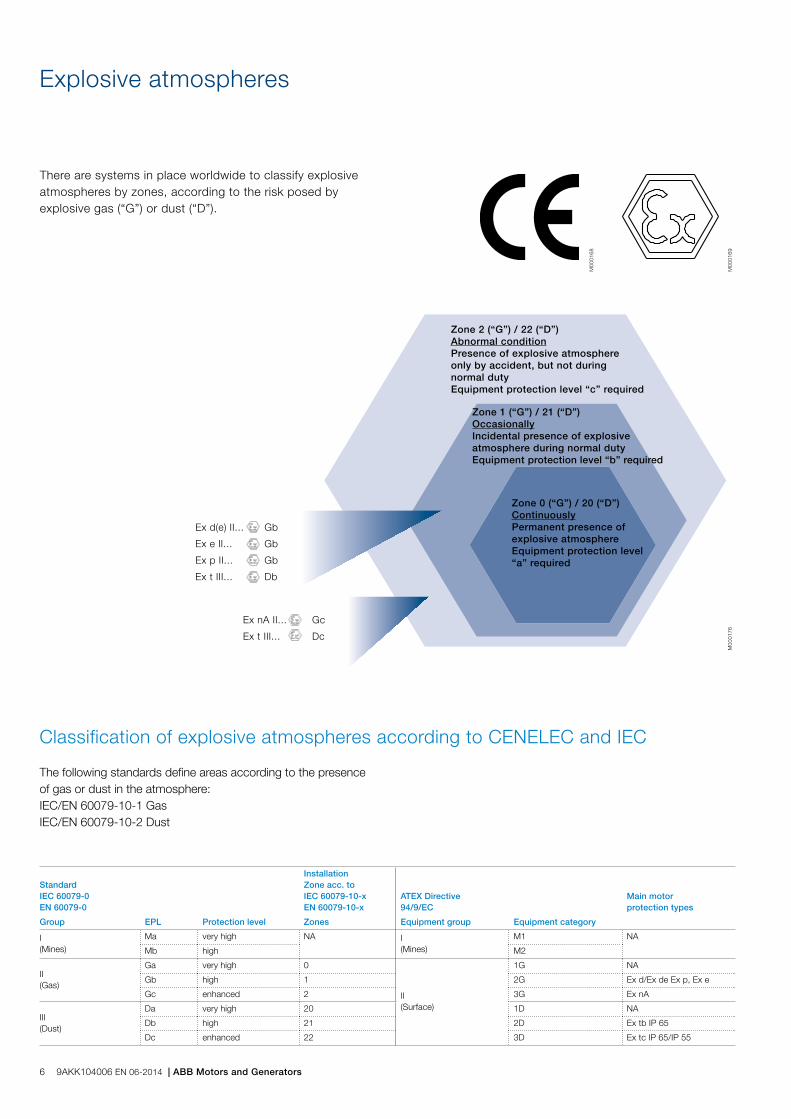
There are systems in place worldwide to classify explosive atmospheres by zones, according to the risk posed by explosive gas (“G”) or dust (“D”).
Classification of explosive atmospheres according to CENELEC and IEC
The following standards define areas according to the presence of gas or dust in the atmosphere:IEC/EN 60079-10-1 Gas IEC/EN 60079-10-2 Dust
M00
0169
M00
0168
Zone 2 (“G”) / 22 (“D”) Abnormal condition Presence of explosive atmosphere only by accident, but not during normal dutyEquipment protection level “c” required
Zone 1 (“G”) / 21 (“D”) Occasionally Incidental presence of explosive atmosphere during normal duty Equipment protection level “b” required
Zone 0 (“G”) / 20 (“D”) Continuously Permanent presence of explosive atmosphere Equipment protection level “a” required
M00
0176
Ex d(e) II... Gb
Ex e II... Gb
Ex p II... Gb
Ex t III... Db
Ex nA II... Gc
Ex t III... Dc
StandardIEC 60079-0EN 60079-0
InstallationZone acc. toIEC 60079-10-xEN 60079-10-x
ATEX Directive94/9/EC
Main motor protection types
Group EPL Protection level Zones Equipment group Equipment category
I(Mines)
Ma very high NA I(Mines)
M1 NA
Mb high M2
II(Gas)
Ga very high 0
II(Surface)
1G NA
Gb high 1 2G Ex d/Ex de Ex p, Ex e
Gc enhanced 2 3G Ex nA
III(Dust)
Da very high 20 1D NA
Db high 21 2D Ex tb IP 65
Dc enhanced 22 3D Ex tc IP 65/IP 55
6 9AKK104006 EN 06-2014 | ABB Motors and Generators

To ensure equipment can be safely used in potentially explosive atmospheres, the explosive atmospheres where the equipment is installed must be known. The temperature class of equipment must be compared with the spontaneous
Marking of temperatures, gas groups and explosive atmospheres
Classification
Temperature class
Ignitiontemp. of gas/vapor °C
Max. permitted temp. of equipment °C
Gas examples
T1 > 450 450 Hydrogen
T2 > 300 < 450 300 Ethanol
T3 > 200 < 300 200 Hydrogen sulfide
T4 > 135 < 200 135 Diethyl ether
T5 > 100 < 135 100 -
T6 > 85 < 100 85 Carbon disulfide
IIA ~120 gases and vapors, e.g. butane / petroleum / propane
IIB ~30 gases and vapors, e.g. ethylene / dimethyl ether / coke oven gas
IIC three gases: hydrogen H2/acetylene C2H2carbon disulfide CS2
Gas subdivisionGas classification
Marking of equipment protection for gas according to ATEX
Marking of equipment protection for gas according to IEC
ignition the equipment of the gas mixtures concerned, and in specific cases the gas group must be known (e.g. flame proof protection).
CE marking Identification of the notified body responsible for the approval. 0081 is the identification number of LCIE
The European Commission mark for Ex products
Equipment group: II for surface industry
Equipment category: 2G for gas environment demanding a high level of protection
II 2G0081
CE Conformity marking Equipment protection marking for gas:
Protection type Ex d = flameproofEquipment group IIB for gas group BTemperature class T4 = max. permitted 135 °CEquipment protection level = level b for gas
Ex d IIB T4 Gb
Example for gas:
Ex d IIB T4 GbProtection type Ex d = flameproofEquipment group IIB for gas group BTemperature class T4 = max. permitted 135 °CEquipment protection level = level b for gas
ABB Motors and Generators | 9AKK104006 EN 02-2016 7
M00
0170
a
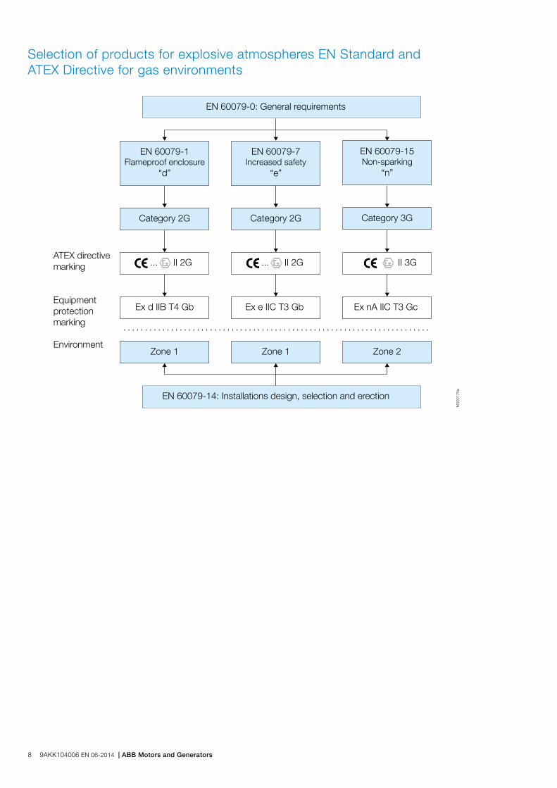
Selection of products for explosive atmospheres EN Standard and ATEX Directive for gas environments
ATEX directive marking
Environment
Equipment protection marking
EN 60079-0: General requirements
Category 2G
Ex d IIB T4 Gb Ex e IIC T3 Gb Ex nA IIC T3 Gc
Category 2G Category 3G
EN 60079-1Flameproof enclosure
“d”
EN 60079-7Increased safety
“e”
EN 60079-15Non-sparking
“n”
... II 2G ... II 2G II 3G
EN 60079-14: Installations design, selection and erection
Zone 1 Zone 1 Zone 2
8 9AKK104006 EN 06-2014 | ABB Motors and Generators

General information about explosive atmospheres
In explosive atmospheres, it is of the utmost importance to ensure the safe use of electrical apparatus. To this end, many countries have regulations concerning both the design and use of such apparatus. These regulations are becoming increasingly harmonized within the framework of IEC recommendations and European Standards. The hazard may
be due to an explosive atmosphere composed of a mixture of gas, vapors or dusts with air. This section is concerned only with safety in explosive gas atmospheres for which European Standards and IEC recommendations exist.
Flameproof enclosure Ex d and Ex de
The motor enclosure is designed in such a way that no internal explosion can be transmitted to the explosive atmosphere surrounding the motor. The enclosure must withstand, without damage, any pressure levels caused by an internal explosion. The shape, length and gap of joints of part assemblies, at shaft openings, cable entries, etc., shall be designed to allow for throttling and cooling of hot gases escaping outside. The standards emphasize the impact of an explosive atmosphere (for instance, explosion pressure) over constructional requirements of such apparatus.
Work on accessories of enclosure componenets is only permitted using prescribed tools. Cable entries must meet the requirements of this type of protection.
The temperature of the motor's external enclosure shall not exceed the self-ignition temperature of the explosive atmosphere of the installation area during operation. For this reason, rated output depends on this rated maximum temperature for the area in question. The standard temperature class on flame proof motors from ABB is T4 (135 °C), other temperature classes as T5 (100 °C) and T6 (85 °C) are available on request.
No motor device outside the flameproof enclosure (e.g., ventilator) shall be a potential source of sparks, arcs or dangerous overheating.
Variants combining two types of protection usually combine “d” and “e” protection. The motor is designed with an Ex d flameproof enclosure, while the terminal box features Ex e increased safety protection. Such design combines the superior safety degree of the “d” type of protection with the high electrical connection requirements of increased safety motors.
Alleinschutz – thermistors as sole protection (optional)Flameproof motors from ABB have been designed to use thermistors as the sole method of protection against overload. This construction, “Alleinschutz”, is available as an option, see variant codes.
“Alleinschutz” refers to the protection of a flameproof motor by a protective device which is triggered by thermistors. The thermistors and relays will switch off the motor in case of overheating before the temperature of the motor's external enclosure exceeds the temperature marking stamped on the rating plate.
Each motor ordered with thermistors as sole protection will be tested, with locked rotor, up to the point where the thermistors trigger the relay to turn off the motor. At the triggering temperature, the motor has to be within the certified temperature class limit.
Only approved relays can be used for “Alleinschutz”.
Please note that sizes 315 to 450 require special technical solutions, consult ABB.
ABB Motors and Generators | 9AKK104006 EN 02-2016 9
Increased safety design, Ex e
The design of this motor type prevents the occurence in operation (including starting and locked rotor situations), in all inner and outer parts of the machine, of sparks, arcs or hot spots that could reach the self-ignition temperature of the surrounding, potentially explosive atmosphere.
This is ensured by applying constructional or dimensional provisions that mainly concern:
− specified minimum values for creepage distances and clearances
− use of tracking-proof isolating materials − suppression of sharp angles where static electrical loads
could build-up − ensuring electrical and mechanical assemblies are tightly
secured − minimum backlash values between stationary and rotating
parts (e.g. air gap, ventilator, etc.) − temperature-rise limits, taking into account locked rotor,
normal operation, accidental mechanical stalling of machine under the most adverse thermal conditions, i.e. when thermal equilibrium of machine is reached while in service.
Temperature rise limits should be considered for two operating aspects; normal operating conditions and accidental stalling conditions.
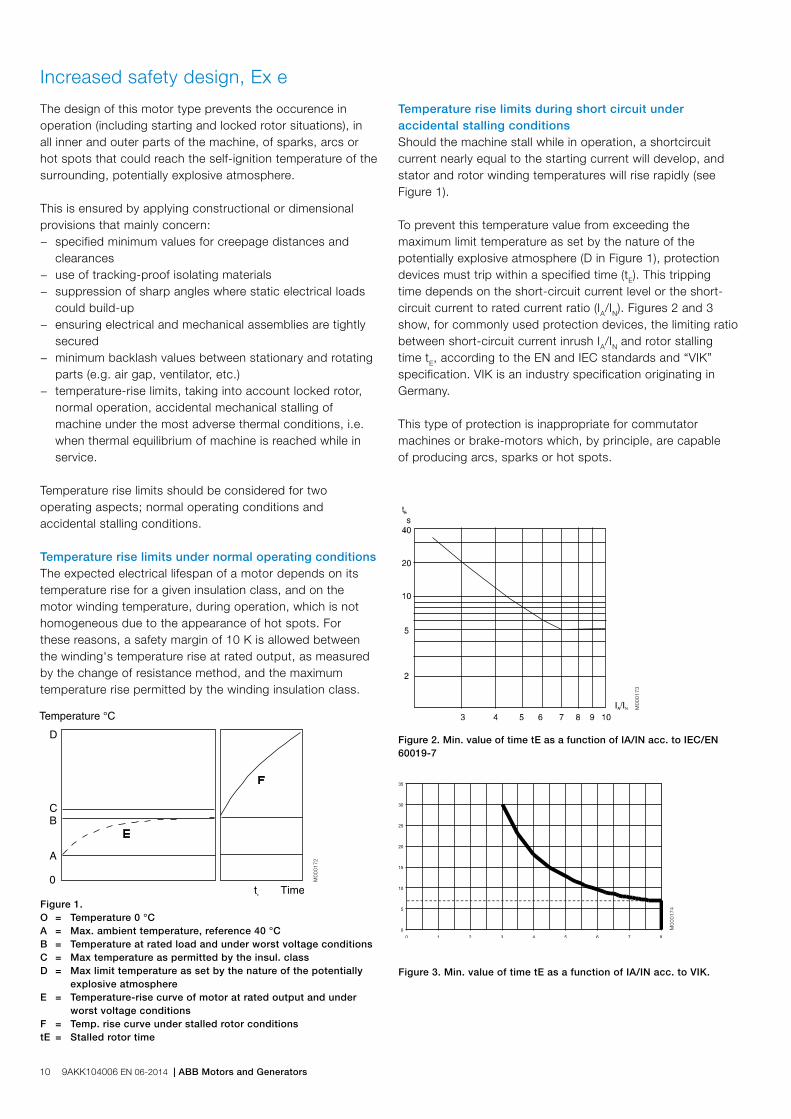
Temperature rise limits under normal operating conditionsThe expected electrical lifespan of a motor depends on its temperature rise for a given insulation class, and on the motor winding temperature, during operation, which is not homogeneous due to the appearance of hot spots. For these reasons, a safety margin of 10 K is allowed between the winding's temperature rise at rated output, as measured by the change of resistance method, and the maximum temperature rise permitted by the winding insulation class.
Figure 1.O = Temperature 0 °C A = Max. ambient temperature, reference 40 °C B = Temperature at rated load and under worst voltage conditions C = Max temperature as permitted by the insul. class D = Max limit temperature as set by the nature of the potentially explosive atmosphere E = Temperature-rise curve of motor at rated output and under worst voltage conditions F = Temp. rise curve under stalled rotor conditions tE = Stalled rotor time
M00
0172
Figure 2. Min. value of time tE as a function of IA/IN acc. to IEC/EN 60019-7
M00
0173
Figure 3. Min. value of time tE as a function of IA/IN acc. to VIK.
M00
0174
Temperature rise limits during short circuit under accidental stalling conditionsShould the machine stall while in operation, a shortcircuit current nearly equal to the starting current will develop, and stator and rotor winding temperatures will rise rapidly (see Figure 1).
To prevent this temperature value from exceeding the maximum limit temperature as set by the nature of the potentially explosive atmosphere (D in Figure 1), protection devices must trip within a specified time (tE). This tripping time depends on the short-circuit current level or the short-circuit current to rated current ratio (IA/IN). Figures 2 and 3 show, for commonly used protection devices, the limiting ratio between short-circuit current inrush IA/IN and rotor stalling time tE, according to the EN and IEC standards and “VIK” specification. VIK is an industry specification originating in Germany.
This type of protection is inappropriate for commutator machines or brake-motors which, by principle, are capable of producing arcs, sparks or hot spots.
10 9AKK104006 EN 06-2014 | ABB Motors and Generators

Non-sparking design, Ex nA
The use of this type of protection is allowed in hazardous areas corresponding to zone 2. The design is known as “non-sparking” because the motor must be designed in such a way that no sparks can occur in any conditions, when used within the ratings specified by the manufacturer, and that no excessive temperatures occur under normal operating conditions, which excludes thermal requirements due to starting or accidental stalling.
Risk assessment and gas tests Non-sparking (Ex nA) and increased safety (Ex e) motors have to meet tough requirements with regard to sparking. The latest IEC and EN standards specify criteria for risk assessment and gas environment tests for rotor and stator designs to show that the motors are spark-free in all operational conditions.
By testing and securing certification for its motors, ABB is helping to streamline the risk assessment process for its customers.
The alternative to testing and certification involves, in the majority of cases, equipping the motor with provision for pre-start ventilation. This means investing in a higher capacity air compressor, piping, and a ventilation control unit. It also requires an additional operation – pre-start ventilation – every time the motor is started.
Benefits of the ABB approach therefore include reduced initial capital expenditure, lower operating costs, and faster starting. Reliability is improved as no additional components are required. Most importantly, ABB’s certified motors offer proven safety.
ABB’s approach to meeting the requirementsFollowing a program of gas environment tests in which all rotor and stator tests were passed, ABB has secured certification for its low voltage cast iron motors for explosive atmospheres with aluminum die cast rotor.
Ex nA motors are certified according to the ATEX 95 Directive with a “voluntary type examination certificate”, and according to the IEC Ex System with a normal certificate.
ABB also provides self-certified non-sparking motors, with a manufacturer Declaration of Conformity.
ABB Motors and Generators | 9AKK104006 EN 02-2016 11
Dual certification Due to the high IP protection class and low surface temperature of the products, the certificates allow also in many cases dual certification for either gas or dust environments. This gives further flexibility as the same motor can either be used in a location with potentially explosive atmospheres with gas, or another with dust. Certification does not include use in a hybrid atmosphere containing both potentially explosive gas and dust at the same time.
The following combinations are possible:
− Ex d IIB/C T4 Gb / Ex tb IIIB/C T125°C Db − Ex de IIB/C T4 Gb / Ex tb IIIB/C T125°C Db − Ex e IIC T3 Gb / Ex tb IIIB/C T125°C Db − Ex nA IIC T3 Gc / Ex tc IIIB/C T125°C Dc
Please refer to the variant code section of flameproof, increased safety and non-sparking motors for further information about availability of dual certification.

Dust ignition protection / Protection by enclosures “t” in explosive atmospheres
Combustible dust is hazardous as it can form potentially explosive atmospheres when dispersed in air. Furthermore, layers of combustible dust may ignite and act as an ignition source for an explosive atmosphere. Explosive atmospheres with dust can be found in a variety of industries such as agriculture, chemicals, plastics, food and beverage.
Selection and installation of electrical equipmentTo ensure equipment can be safely used in explosive atmospheres with dust, it is vital that the following issues are taken into account when selecting product:
1. Type of dust: − Will a cloud of dust be present around the product or − will a layer of dust build up on the product and if so, what
will be the maximum thickness of the layer between two cleaning/maintenance procedures.
2. Characteristics of the dust: − Is the dust electrically conductive or non-conductive?
3. Ignition temperature of the dust: − TCl: Ignition temperature of dust in a “cloud” or − T5mm: Ignition temperature of a 5 mm dust layer
Selection and installation of the product according to IEC/EN60079 part 14: Electrical installations design, selection and erection. Please see the tables on the pages 12 and 13. Please see the table on page 14.
This protection prevents any explosion of dust because: − The ingress of dust into the motor is prevented by the IP
protection, being either IP 55 (“dust protected”) or IP 65 (“dust tight”).
− The maximum surface temperature outside the motor must not exceed the temperature class for which the motor is certified.
− No sparks must occur outside the motor enclosure.
Certification: Ex tb IIIB/C T...°C Db (for zone 21) motors are certified according to ATEX with an EC type examination certificate and according to the IEC Ex System. Ex tc IIIB/C T...°C Dc (for zone 22) motors are certified according to ATEX with a “voluntary type examination certificate” and according to the IEC Ex System.
The standard surface temperature class on dust ignition protection motors from ABB is T125 °C, other temperature classes are available on request.
Dust classificationTCL (cloud) °C
T5mm (layer) °C
Surface temperature provided that dust layer below 5 mm
Food/Feeder industry Wheat 350 270 195
Barley, corn 380 280 205
Sugar 350 430 233
Natural materials Wood 330 280 205
Charcoal 520 230 195
Hard coal 460 240 165
Chemicals PVC 450 330 255
Synth. rubber 470 220 145
Sulfur 240 250 160
Source BIA-report 13/97 HVBG
Dust subdivisionsIIIA combustible flyings
IIIB non-conductive dust
IIIC conductive dust
12 9AKK104006 EN 06-2014 | ABB Motors and Generators

Marking of equipment protection for dust according to ATEX
Marking of equipment protection for dust according to IEC
CE marking Identification of the notified body responsible for the approval. 0081 is the identification number of LCIE
The European Commission mark for Ex products
Equipment group: II for surface industry
Equipment category: 2D for dust environment demanding a high level of protection
II 2 D0081
CE Conformity marking Equipment protection for dust:
Ex tc IIIC T125 °C DcProtection by enclosure
Equipment group IIIC for conductive dust
Temperature class
Equipment protection level = level c for dust
Example for dust:
Ex tc IIIC T125 °C DcProtection by enclosure
Equipment group IIIC for conductive dust
Temperature class
Equipment protection level = level c for dust
ABB Motors and Generators | 9AKK104006 EN 02-2016 13
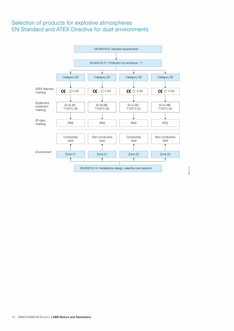
Selection of products for explosive atmospheres EN Standard and ATEX Directive for dust environments
M00
0171
a
ATEX directive marking
IP class marking
Environment
Equipment protection marking
EN 60079-0: General requirements
EN 60079-31: Protection by enclosure ”t”
Category 2D
... II 2D ... II 2D II 3D II 3D
IP65 IP65 IP65 IP55
Conductivedust
Non-conductivedust
Conductivedust
Non-conductivedust
Ex tb IIIC T125°C Db
Ex tb IIIB T125°C Db
Ex tc IIIC T125°C Dc
Ex tc IIIB T125°C Dc
Category 2D Category 3D Category 3D
Zone 21 Zone 21 Zone 22 Zone 22
EN 60079-14: Installations design, selection and erection
14 9AKK104006 EN 06-2014 | ABB Motors and Generators

Testing and certificates
Motors for explosive atmospheres have to be officially approved by a recognized test organization, authorized to issue test certificates, to ensure compliance with standards for this type of equipment.
ABB low voltage motors for explosive atmospheres are classified according to the categories, protection types and equipment protection type which are specified in the relevant standards.
Depending on the nature of the potentially explosive atmosphere, it is the responsibility of the user to determine which group and which maximum surface temperature should be specified for the motor installation.The motors are rated and certified for ambient temperature between –20 °C and +40 °C according to standards. For ambient temperatures below –20 °C and above +40 °C certificates are available for most of the motors.
ABB’s motors conform to the stringent standards set by CENELEC (European Committee for Electrotechnical Standardization) and IEC (International Electrotechnical Commission), and are approved by testing laboratories (ExNB/Notified Body) and certification bodies (ExCB).
The motors can be certified according to the ATEX Directive by any of the Notified Bodies “ExNB” of EU member countries. These motors are therefore acceptable in all EU countries and many other countries. In addition, IECEx certificates are available for the motors. These certificates can be issued by any registered IECEx certification body (ExCB) worldwide.
Typical national certificates available include CU-TR for Russia, Kazakhstan and Belarus, INMETRO for Brazil and CQST for China. KOSHA certification for Korea is different, because the organization importing the motor to Korea has to apply on a case-by-case basis.
ABB Motors and Generators | 9AKK104006 EN 02-2016 15

Since the validation of IEC/EN 60034-30:2008 and its refinedversion IEC/EN 60034-30-1:2014, a worldwide energy efficiency classification system has existed for low voltage three-phase asynchronous motors. This system increases the level of harmonization in efficiency regulations around the world and also covers motors for explosive atmospheres. IEC/EN 60034-30-1:2014 defines International Efficiency (IE) classes for single speed, three-phase, 50 and 60 Hz induction motors. The standard is part of an effort to unify motor testing procedures as well as effi ciency and product labeling requirements to enable motor purchasers worldwide to easily recognize premium efficiency products. The efficiency levels defined in IEC/EN 60034-30-1 are based on test methods specified in IEC/EN 60034-2-1 which has been updated to edition 2.0, 2014-06.
M00
0700
To promote transparency in the market, IEC 60034-30 states that both the effi ciency class and effi ciency value must be shown on the motor rating plate and in product documentation. The documentation must clearly indicate the effi ciency testing method used as the different methods can produce differing results.
As the scope of IEC/EN 60034-30 also covers for explosive atmospheres, these motors can be labeled with the IE -code. Ex-motors are already included in many MEPS (Minimum Energy Performance Standard) schemes around the world; Australia, the US, Canada, China, Korea and Brazil.
International motor efficiency standards
■ Australian MEPS, Australia (and New Zealand)2001(2002)/rev. 2006
● ANZEx■ PBE Brazilian Labelling Program, Brazil
2009/ IE2 efficiency level 2012
● Inmetro
■ Mexican MEPS, Mexico2010
■ EISA, USA2007/rev. 2010
● NEC
■ China Energy Label, China2008/ rev. 2012
● CNEx
■ Korean MEPS, Korea2008/ introduced in 3 phases 2008-2011
● KOSHA/KGS
■ EU MEPS, EUEC 640/2009EU 4/2014
● ATEX (Europe)
■ Energy Efficiency Act, Canada1997/rev. 1999 and 2012
● CEC
■ Turkish MEPS, Turkey2012
● PESO
● TIIS
● ITRI
● CU-TR
● SABS
● CU-TR
● CU-TR
■ Requirements for efficiency
● Requirements/Ex-certification
● ● ● IECEx (Worldwide)
UkrSEPRO
16 9AKK104006 EN 06-2014 | ABB Motors and Generators

IEC/EN 60034-30-1:2014IEC/EN 60034-30-1:2014 defines four International Efficiency (IE) classes for single speed electric motors that are rated according to IEC 60034-1 or IEC 60079-0 (explosive atmospheres) and designed for operation on sinusoidal voltage.
− IE4 = Super premium effi ciency − IE3 = Premium efficiency, identical to ‘NEMA Premium’ in
the USA for 60 Hz − IE2 = High efficiency, identical to EPAct in the USA for
60 Hz − IE1 = Standard effi ciency
Efficiency levels defined in IEC/EN 60034-30-1 are based on test methods specified in IEC 60034-2-1.
IEC/EN 60034-30-1 covers power range 120 W to 1000 kW. All technical constructions of electric motors are covered as long as they are rated for direct on-line operation. The coverage of the standard includes:
− Single speed electric motors (single and three-phase), 50 and 60 Hz
− 2, 4, 6 and 8 poles − Rated output PN from 0.12 kW to 1000 kW − Rated voltage UN above 50 V up to 1 kV − Motors, capable of continuous operation at their rated
power with a temperature rise within the specified insulation temperature class
− Motors, marked with any ambient temperature within the range of –20 °C to +60 °C
− Motors, marked with an altitude up to 4000 m above sea level
The following motors are excluded from IEC/EN 60034-30-1:
− Single-speed motors with 10 or more poles or multi-speed motors
− Motors completely integrated into a machine (for example, pump, fan or compressor) that cannot be tested separately from machine
− Brake motors, when the brake can not be dismantled or separately fed
ABB and efficiency standards ABB determines efficiency values according to IEC 60034-2-1 using the low uncertainty method (i.e. indirect method), with additional load losses determined by measurement.
As the world market leader, ABB offers the largest range of LV motors available. It has long advocated the need for efficiency in motors, and high efficiency products have formed the core of its portfolio for many years. The core of ABB’s Process performance range is based on full range in IE2 and IE3 motors – with many available from stock.
IE Classes - 4-pole motors
ABB Motors and Generators | 9AKK104006 EN 02-2016 17

Minimum efficiency values defined in IEC/EN 60034-30-1: 2014 (reference values at 50 Hz,based on test methods specified in IEC 60034-2-1 which has been updated to edition 2.0, 2014-06).
IE1Standard efficiency
IE2High efficiency
IE3Premium efficiency
IE4Super Premium efficiencyOutput
kW 2 pole 4 pole 6 pole 8 pole 2 pole 4 pole 6 pole 8 pole 2 pole 4 pole 6 pole 8 pole 2 pole 4 pole 6 pole 8 pole
0.12 45.0 50.0 38.3 31.0 53.6 59.1 50.6 39.8 60.8 64.8 57.7 50.7 66.5 69.8 64.9 62.3
0.18 52.8 57.0 45.5 38.0 60.4 64.7 56.6 45.9 65.9 69.9 63.9 58.7 70.8 74.7 70.1 67.2
0.20 54.6 58.5 47.6 39.7 61.9 65.9 58.2 47.4 67.2 71.1 65.4 60.6 71.9 75.8 71.4 68.4
0.25 58.2 61.5 52.1 43.4 64.8 68.5 61.6 50.6 69.7 73.5 68.6 64.1 74.3 77.9 74.1 70.8
0.37 63.9 66.0 59.7 49.7 69.5 72.7 67.6 56.1 73.8 77.3 73.5 69.3 78.1 81.1 78.0 74.3
0.40 64.9 66.8 61.1 50.9 70.4 73.5 68.8 57.2 74.6 78.0 74.4 70.1 78.9 81.7 78.7 74.9
0.55 69.0 70.0 65.8 56.1 74.1 77.1 73.1 61.7 77.8 80.8 77.2 73.0 81.5 83.9 80.9 77.0
075 72.1 72.1 70.0 61.2 77.4 79.6 75.9 66.2 80.7 82.5 78.9 75.0 83.5 85.7 82.7 78.4
1.1 75.0 75.0 72.9 66.5 79.6 81.4 78.1 70.8 82.7 84.1 81.0 77.7 85.2 87.2 84.5 80.8
1.5 77.2 77.2 75.2 70.2 81.3 82.8 79.8 74.1 84.2 85.3 82.5 79.7 86.5 88.2 85.9 82.6
2.2 79.7 79.7 77.7 74.2 83.2 84.3 81.8 77.6 85.9 86.7 84.3 81.9 88.0 89.5 87.4 84.5
3 81.5 81.5 79.7 77.0 84.6 85.5 83.3 80.0 87.1 87.7 85.6 83.5 89.1 90.4 88.6 85.9
4 83.1 83.1 81.4 79.2 85.8 86.6 84.6 81.9 88.1 88.6 86.8 84.8 90.0 91.1 89.5 87.1
5.5 84.7 84.7 93.1 81.4 87.0 87.7 86.0 83.8 89.2 89.6 88.0 86.2 90.9 91.9 90.5 88.3
7.5 86.0 86.0 84.7 83.1 88.1 88.7 87.2 85.3 90.1 90.4 89.1 87.3 91.7 92.6 91.3 89.3
11 87.6 87.6 86.4 85.0 89.4 89.8 88.7 86.9 91.2 91.4 90.3 88.6 92.6 93.3 92.3 90.4
15 88.7 88.7 87.7 86.2 90.3 90.6 89.7 88.0 91.9 92.1 91.2 89.6 93.3 93.9 92.9 91.2
18.5 89.3 89.3 88.6 86.9 90.9 91.2 90.4 88.6 82.4 92.6 91.7 90.1 93.7 94.2 93.4 91.7
22 89.9 89.9 89.2 87.4 91.3 91.6 90.9 89.1 92.7 93.0 92.2 90.6 94.0 94.5 93.7 92.1
30 90.7 90.7 90.2 88.3 92.0 92.3 91.7 89.8 93.3 93.6 92.9 91.3 94.5 94.9 94.2 92.7
37 91.2 91.2 90.8 88.8 92.5 92.7 92.2 90.3 93.7 93.9 93.3 91.8 94.8 95.2 94.5 93.1
45 91.7 91.7 91.4 89.2 92.9 93.1 92.7 90.7 94.0 94.2 93.7 92.2 95.0 95.4 94.8 93.4
55 92.1 92.1 91.9 89.7 93.2 93.5 93.1 91.0 94.3 94.6 94.1 92.5 95.3 95.7 95.1 93.7
75 92.7 92.7 92.6 90.3 93.8 94.0 93.7 91.6 94.7 95.0 94.6 93.1 95.6 96.0 95.4 94.2
90 93.0 93.0 92.9 90.7 94.1 94.2 94.0 91.9 95.0 95.2 94.9 93.4 95.8 96.1 95.6 94.4
110 93.3 93.3 93.3 91.1 94.3 94.5 94.3 92.3 95.2 95.4 95.1 93.7 96.0 96.3 95.8 94.7
132 93.5 93.5 93.5 91.5 94.6 94.7 94.6 92.6 95.4 95.6 95.4 94.0 96.2 96.4 96.0 94.9
160 93.8 93.8 93.8 91.9 94.8 94.9 94.8 93.0 95.6 95.8 95.6 94.3 96.3 96.6 96.2 95.1
200 94.0 94.0 94.0 92.5 95.0 95.1 95.0 93.5 95.8 96.0 95.8 94.6 96.5 96.7 96.3 95.4
250 94.0 94.0 94.0 92.5 95.0 95.1 95.0 93.5 95.8 96.0 95.8 94.6 96.5 96.7 96.5 95.4
315 94.0 94.0 94.0 92.5 95.0 95.1 95.0 93.5 95.8 96.0 95.8 94.6 96.5 96.7 96.6 95.4
355 94.0 94.0 94.0 92.5 95.0 95.1 95.0 93.5 95.8 96.0 95.8 94.6 96.5 96.7 96.6 95.4
400 94.0 94.0 94.0 92.5 95.0 95.1 95.0 93.5 95.8 96.0 95.8 94.6 96.5 96.7 96.6 95.4
450 94.0 94.0 94.0 92.5 95.0 95.1 95.0 93.5 95.8 96.0 95.8 94.6 96.5 96.7 96.6 95.4
500-1000 94.0 94.0 94.0 92.5 95.0 95.1 95.0 93.5 95.8 96.0 95.8 94.6 96.5 96.7 96.6 95.4
18 9AKK104006 EN 06-2014 | ABB Motors and Generators
Code I / code II Product code pos. 12
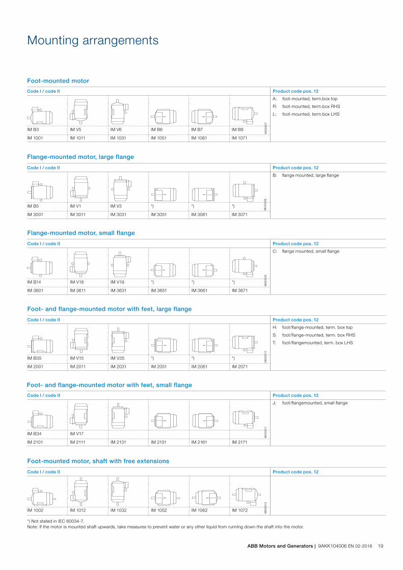
C: flange mounted, small flange
IM B14 IM V18 IM V19 *) *) *)
IM 3601 IM 3611 IM 3631 IM 3651 IM 3661 IM 3671
Code I / code II Product code pos. 12
A: foot-mounted, term.box top
R: foot-mounted, term.box RHS
L: foot-mounted, term.box LHS
IM B3 IM V5 IM V6 IM B6 IM B7 IM B8
IM 1001 IM 1011 IM 1031 IM 1051 IM 1061 IM 1071
Code I / code II Product code pos. 12
B: flange mounted, large flange
IM B5 IM V1 IM V3 *) *) *)
IM 3001 IM 3011 IM 3031 IM 3051 IM 3061 IM 3071
M00
0007
M00
0008
M00
0009
Foot-mounted motor
Flange-mounted motor, large flange
Flange-mounted motor, small flange
Code I / code II Product code pos. 12
H: foot/flange-mounted, term. box top
S: foot/flange-mounted, term. box RHS
T: foot/flangemounted, term. box LHS
IM B35 IM V15 IM V35 *) *) *)
IM 2001 IM 2011 IM 2031 IM 2051 IM 2061 IM 2071
M00
0010
Foot- and flange-mounted motor with feet, large flange
Code I / code II Product code pos. 12
J: foot/flangemounted, small flange
IM B34 IM V17
IM 2101 IM 2111 IM 2131 IM 2151 IM 2161 IM 2171
M00
0011
Foot- and flange-mounted motor with feet, small flange
Code I / code II Product code pos. 12
IM 1002 IM 1012 IM 1032 IM 1052 IM 1062 IM 1072
*) Not stated in IEC 60034-7.Note: If the motor is mounted shaft upwards, take measures to prevent water or any other liquid from running down the shaft into the motor.
M00
0012
Foot-mounted motor, shaft with free extensions
Mounting arrangements
ABB Motors and Generators | 9AKK104006 EN 02-2016 19
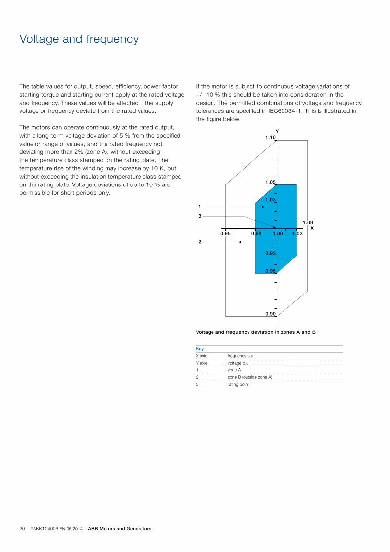
The table values for output, speed, efficiency, power factor, starting torque and starting current apply at the rated voltage and frequency. These values will be affected if the supply voltage or frequency deviate from the rated values.
The motors can operate continuously at the rated output, with a long-term voltage deviation of 5 % from the specified value or range of values, and the rated frequency not deviating more than 2% (zone A), without exceeding the temperature class stamped on the rating plate. The temperature rise of the winding may increase by 10 K, but without exceeding the insulation temperature class stamped on the rating plate. Voltage deviations of up to 10 % are permissible for short periods only.
Voltage and frequency
If the motor is subject to continuous voltage variations of +/- 10 % this should be taken into consideration in the design. The permitted combinations of voltage and frequency tolerances are specified in IEC60034-1. This is illustrated in the figure below.
1
2
3
Y
X1.00 1.02
0.90
0.98
1.10
0.93
0.95
1.05
1.03
0.95
1.09
Voltage and frequency deviation in zones A and B
Key
X axle frequency p.u.
Y axle voltage p.u.
1 zone A
2 zone B (outside zone A)
3 rating point
20 9AKK104006 EN 06-2014 | ABB Motors and Generators

Cooling
Designation system concerning methods of cooling refers to standard IEC 60034-6. Standard cooling method is IC411. For further information please see the variant code section of each motor type for availability of other cooling methods.
Explanation of the product code
International Cooling Circuit arrangement Primary coolant Method of movement of primary coolant
Secondary coolant Method of movement of secondary coolant
IC 4 (A) 1 (A) 61 2 3 4 5
Position 1
0: Free circulation (open circuit)
4: Frame surface cooled
Position 2
A: For air (omitted for simplified designation)
Position 3
0: Free convection
1: Self-circulation
6: Machine-mounted independent component
Position 4
A: For air (omitted for simplified designation)
W: For water
Position 5
0: Free convection
1: Self-circulation
6: Machine-mounted independent component
8: Relative displacement
ABB Motors and Generators | 9AKK104006 EN 02-2016 21

Degrees of protection: IP code and resistance to impact
Classification of degrees of protection provided by enclosures of rotating machines are refers to: Standard IEC 60034-5 or EN 60529 for IP code
Ingress protection Degree of protection to persons and to parts of the motors inside the enclosure
Degree of protection provided by the enclosure with respect to harmful effects due to ingress of water
IP 5 51 2
Position 1
2: Motors protected against solid objects greater than 12 mm
4: Motors protected against solid objects greater than 1 mm
5: Dust-protected motors
6: Dust-tight motors
Position 2
3: Motors protected against spraying water
4: Motors protected against splashing water
5: Motors protected against water jets
6: Motors protected against heavy seas
IP protectionProtection of persons against getting in contact with (or approaching) live parts and against contact with moving parts inside the enclosure. Also protection of the machine against ingress of solid foreign objects. Protection of machines against the harmful effects due to the ingress of water.
Explanation of the IP code
Resistance to impactABB's motors for explosive atmospheres have been tested for resistance to impact as described in IEC/EN 60079-0. The more demanding high risk of mechanical danger limits have been used as qualification criteria. For group II and III motors this means an impact energy strenght of 7J for both enclosure and fan cover.
Following IEC/EN 60079-0 non-metallic parts of enclosures in motors for explosive atmospheres must be thermal endurance tested for the temperature range the motors are designed for. Non-metallic parts are, for instance, rubber seals and gaskets. Thermal endurance tests and impact tests are carried out before the ingress protection test. This ensures that the motors meet the ingress protection level also after been put in service.
22 9AKK104006 EN 06-2014 | ABB Motors and Generators
Insulation
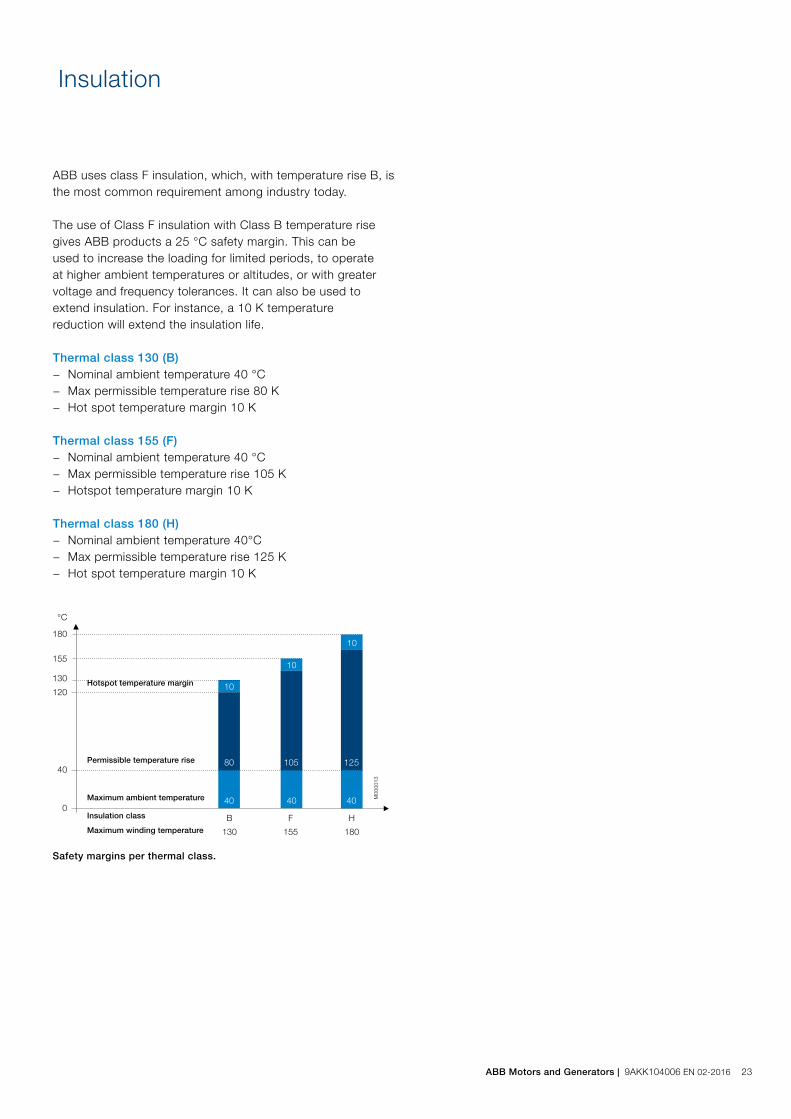
ABB uses class F insulation, which, with temperature rise B, is the most common requirement among industry today.
The use of Class F insulation with Class B temperature risegives ABB products a 25 °C safety margin. This can beused to increase the loading for limited periods, to operateat higher ambient temperatures or altitudes, or with greatervoltage and frequency tolerances. It can also be used toextend insulation. For instance, a 10 K temperaturereduction will extend the insulation life.
Thermal class 130 (B) − Nominal ambient temperature 40 °C − Max permissible temperature rise 80 K − Hot spot temperature margin 10 K
Thermal class 155 (F) − Nominal ambient temperature 40 °C − Max permissible temperature rise 105 K − Hotspot temperature margin 10 K
Thermal class 180 (H) − Nominal ambient temperature 40°C − Max permissible temperature rise 125 K − Hot spot temperature margin 10 K
Safety margins per thermal class.
180
155
130
120
40
0
°C
B
130
F
155
H
180
10
10
10
40 40 40
80 105 125
Hotspot temperature margin
Permissible temperature rise
Maximum ambient temperature
Insulation class
Maximum winding temperature
M00
0013
ABB Motors and Generators | 9AKK104006 EN 02-2016 23

The surface treatment categorization of ABB motors is basedon the ISO 12944 standard. ISO 12994-5 divides paint system durability into three categories: low (L), medium (M), and high (H). Low durability corresponds to a lifetime of 2 – 5 years, medium to 5 – 15 years, and high durability to over 15 years.
The durability range is not a guaranteed lifetime. Its purpose is to help the owner of the motor plan for appropriate maintenance intervals. More frequent maintenance may be required because of fading, chalking, contamination, wear and tear, or for other reasons.
ABB’s standard surface treatment is corrosivity category C3,durability range M (which equal to medium corrosivity and medium durability). Special surface treatment is available in corrosivity categories C4 and C5-M, durability class M for both. In addition, surface treatment according to the NORSOK standard for offshore environments is available as an option.
The standard ABB paint color for motors is Munsell blue 8B4.5/3.25.
Surface treatment
Corrositivity categories Outdoor atmospheres Indoor atmospheres Use in ABB motors
C1, very low Not used Heated buildings with clean atmospheres Not available
C2, low Atmospheres with low level pollution, mostlyrural areas
Unheated buildings where condensation mayoccur, such as depots and sports halls
Not available
C3, medium Urban and industrial atmospheres, moderatesulfur dioxide pollution. Coastal areas withlow salinity
Production rooms with high humidity andsome air pollution; food processing plants,laundries, breweries, dairies
Standard treatment
C4, high Industrial areas and coastal areas with moderatesalinity
Chemical plants, swimming pools, coastalship- and boatyards
Optional treatment for cast iron motors, variantcode 115
C5-I, very high (industrial) Industrial areas and coastal areas with highhumidity and aggressive atmosphere
Buildings or areas with nearly permanentcondensation and high pollution
Not available
C5-M, very high (marine) Coastal and offshore areas with high salinity Buildings or areas with nearly permanentcondensation and high pollution
Optional treatment for cast iron motors, variantcode 754, 710 and 711
Atmospheric corrosivity categories and recommended environments.
24 9AKK104006 EN 06-2014 | ABB Motors and Generators

Low voltage motors and frequency converters for explosive atmospheres
Frequency converters provide significant benefits when used with motors for explosive atmospheres. The advantages include better process control through regulation of the motor speed, as well as energy savings, and therefore improved environmental performance.
Certain criteria must be taken into account to ensure the safety of the frequency converter and motor combination, as well as the maximum usability of the application. The requirements depend on the protection type in use and whether the motor is regarded as being one component within a wider system or a separate subsystem.
ABB offers motors for explosive atmospheres for use with variable speed drives with the following protection types: flameproof, increased safety (on request), non-sparking, and dust ignition protection. These motors are designed and certified for operation with frequency converters. Instructions for the different protection types, as well as for the most common types of converter, are provided below. If further information is needed, please do not hesitate to contact ABB.
A. Main requirements for hazardous area motors used with variable speed drives1. Flameproof motors (Ex d, Ex de)The standards specify that the motor must be dimensioned so that its maximum outer surface temperature is limited according to the temperature class. In most cases this requires either type tests or control of the outer surface temperature of the motor.
Most ABB flameproof motors for temperature class T4 have been type tested with ABB ACS800 and ACS880 converters utilizing Direct Torque Control (DTC) as well as with ABB ACS550 frequency converters, and these combinations can be selected using the loadability curves shown in Figures 2 and 4. Combined tests with the above mentioned converters are needed only if the limits of the loadability curves are exceeded. In such cases separate certification of the motor and converter combination may also be required.
In the case of other voltage source converters using pulse width modulation (PWM) with scalar or vector control, combined tests are needed to confirm the correct thermal performance of the motor. These tests can be avoided if the motor is fitted with thermal sensors to control the surface temperature. Such motors have the following additional markings on their rating plate: -“PTC” with the tripping temperature and “DIN 44081/82”. Alternatively can Pt100s be used to monitor the surface temperature, in that case is the motor provided with an additional plate telling the tripping temperature that should be set.
In the case of voltage source PWM converters, with a minimum switching frequency of 3 kHz or higher, the instructions provided in section B/2.4 can be used for preliminary dimensioning.
For more information on using flameproof motors for temperature classes T5 and T6 with variable speed drives, please contact ABB.
2. Increased safety motors (Ex e)The motor should always be tested together with the specified converter, and ABB therefore does not recommend the use of low voltage increased safety motors with variable speed drives.
3. Non-sparking motors (Ex nA)According to the standards, the combination of motor and converter must be tested as a unit with the specified converter or a comparable one or dimensioned by calculation.
ABB non-sparking cast iron motors have been type tested with ABB ACS800 and ACS880 converters utilizing DTC control as well as with ABB ACS550 converters, and these combinations can be selected using the dimensioning instructions provided in section B/2.2. Combined tests with the above mentioned converters are needed only if the limits of the loadability curves are exceeded. In such cases separate certification of the motor and converter combination may also be required.
In the case of other voltage source PWM converters, combined tests are needed to confirm the correct thermal behavior of the motor. For preliminary dimensioning purposes, the instructions provided in section B/2.4 can be used. The final values must be verified by combined tests.
4. Dust ignition protection motors (Ex t)The standards specify that the motor must be dimensioned so that its maximum outer surface temperature is limited according to the temperature class (e.g. T125 °C or T150 °C). For more information on temperature classes lower than 125 °C, please contact ABB.
ABB Ex t motors (T125 °C and T150 °C) have been type tested with ACS800 and ACS880 converters utilizing DTC control as well as with ABB ACS550 converters, and these combinations can be selected using the dimensioning instructions provided in section B/2.4. Combined tests with above mentioned converters are needed only if the limits of the loadability curves are exceeded. On such cases also separate certification of the motor and converter combination may be required.
ABB Motors and Generators | 9AKK104006 EN 02-2016 25

In the case of any other voltage source PWM converter, combined tests are needed to confirm the correct thermal performance of the motor. These tests can be avoided if the motor is fitted with thermal sensors to control the surface temperature. Such motors have the following additional markings on their rating plate: -“PTC” with the tripping temperature and “DIN 44081/82”.
In the case of voltage source PWM converters with a minimum switching frequency of 3 kHz or higher, the instructions provided in section B/2.2 can be used for preliminary dimensioning.
B. Other safety criteriaThese criteria are imposed by the competent bodies in order to ensure the safe use of motors with converters in explosive atmospheres.
1. Type tests and certificationABB has certified the complete range of Ex d, Ex de, Ex nA and Ex t motors for operation with frequency converters. The certification is based on extensive type testing of the different motor types together with ABB ACS 800, ACS 880 and ACS 550 converters.
2. Motor dimensioning for variable speed applications2.1 GeneralThe voltage (or current) fed by the frequency converter is not purely sinusoidal. This may increase motor losses, vibration, and noise. Furthermore, a change in the distribution of the losses may affect the motor temperature balance and lead to increased temperature.
When the motor is operating at low speeds the cooling capacity of the ventilation fan is decreased, which reduces the motor’s loadability. A separate constant speed fan can be used to increase cooling capacity and loadability at low speeds.
When dimensioning a motor for variable speed applications, the continuous thermal dimensioning and short time overloads should be considered.
2.2 Thermal dimensioning with ABB ACS800 and ACS880 converters utilizing DTC controlIn the case of ABB ACS800 and ACS880 converters utilizing DTC control, dimensioning can be done using the loadability curves (or load capacity curves) in Figures 2 and 3. The loadability curves show the maximum permitted continuous output torque of the motor as a function of supply frequency. The output torque is given as a percentage of the motor’s nominal torque.
In case scalar control mode is used might a further reduce of load be required.
The most convenient method to dimension the motor is to utilize ABB’s DriveSize program. This tool can be downloaded from the ABB website (www.abb.com/motors&generators)The loadability curves are based on nominal supply voltage.
Note: the maximum speed of the motor must not be exceeded even if the loadability curves extend to 100 Hz.
2.3 Thermal dimensioning with ABB ACS550 convertersIn the case of ABB ACS550 converters, dimensioning can be done using the loadability curves in Figures 4 and 5. Also in the case of ACS550 driven applications, the most convenient method to dimension the motor is to utilize ABB’s DriveSize program.
Note 1. The loadability curves in Figures 4 and 5 are based on a switching frequency of 3 kHz.
Note 2. For constant torque applications the lowest permitted continuous operating frequency is 15 Hz.
Note 3. For quadratic torque applications the lowest continuous operating frequency is 5 Hz.
2.4 Thermal dimensioning with other voltage source PWM-type convertersFor VSDs other than DTC-controlled, ACS800, ACS880 and ACS550 converters, preliminary dimensioning can be done using the loadability curves in Figures 4 and 5. The utilization of these curves assumes a minimum switching frequency of 3 kHz.
To ensure safe operation, the combination of motor and frequency converter must either be tested for the specific protection type or thermal sensors must be fitted to control the surface temperature. Frequencies below 15 Hz shall be avoided or tested separately.
Note: the actual thermal loadability of a motor may be lower than shown by the guideline curves.
2.5 Short time overloadsShort time overloading is usually possible with ABB flameproof motors. For the exact values, please see the motor’s rating plate.
Overloadability is specified by three factors:IOL Maximum short time currentTOL Length of permitted overload periodTCOOL Cooling time required after each overload period. During the cooling period the motor current and torque must remain below the limit of permitted continuous loadability.
3. Operating speedWhen a motor is used with a frequency converter, its actual operating speed may deviate considerably from its nominal speed (i.e. the speed stamped on the rating plate). When operating at higher speeds, ensure that the highest permissible rotational speed of the motor, or the critical speed of the equipment as a whole, is not exceeded.
The permitted maximum speed must be stated on a rating plate. This can be either a separate plate or the regular plate required for variable speed drive motors.
26 9AKK104006 EN 06-2014 | ABB Motors and Generators
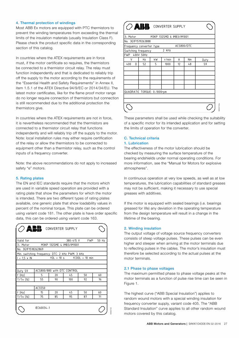
4. Thermal protection of windingsMost ABB Ex motors are equipped with PTC thermistors to prevent the winding temperatures from exceeding the thermal limits of the insulation materials (usually Insulation Class F). Please check the product specific data in the corresponding section of this catalog.
In countries where the ATEX requirements are in force must, if the motor certificate so requires, the thermistors be connected to a thermistor circuit relay. The relay must function independently and that is dedicated to reliably trip off the supply to the motor according to the requirements of the “Essential Health and Safety Requirements” in Annex II, item 1.5.1 of the ATEX Directive 94/9/EC or 2014/34/EU. The latest motor certificates, like for the flame proof motor range do no longer require connection of thermistors but connection is still recommended due to the additional protection the thermistors give.
In countries where the ATEX requirements are not in force, it is nevertheless recommended that the thermistors are connected to a thermistor circuit relay that functions independently and will reliably trip off the supply to the motor.Note: local installation rules may either require certification of the relay or allow the thermistors to be connected to equipment other than a thermistor relay, such as the control inputs of a frequency converter.
Note: the above recommendations do not apply to increased safety “e” motors.
5. Rating platesThe EN and IEC standards require that the motors which are used in variable speed operation are provided with a rating plate that show the parameters for which the motor is intended. There are two different types of rating plates available, one generic plate that show loadability values in percent of the nominal torque. This plate can be ordered using variant code 181. The other plate is have order specific data, this can be ordered using variant code 163.
These parameters shall be used while checking the suitability of a specific motor for its intended application and for setting the limits of operation for the converter.
C. Technical criteria1. LubricationThe effectiveness of the motor lubrication should be checked by measuring the surface temperature of the bearing endshields under normal operating conditions. For more information, see the “Manual for Motors for explosive atmospheres”.
In continuous operation at very low speeds, as well as at low temperatures, the lubrication capabilities of standard greases may not be sufficient, making it necessary to use special greases with additives.
If the motor is equipped with sealed bearings (i.e. bearings greased for life) any deviation in the operating temperature from the design temperature will result in a change in the lifetime of the bearing.
2. Winding insulationThe output voltage of voltage source frequency converters consists of steep voltage pulses. These pulses can be even higher and steeper when arriving at the motor terminals due to reflecting pulses in the cables. The motor’s insulation must therefore be selected according to the actual pulses at the motor terminals.
2.1 Phase to phase voltagesThe maximum permitted phase to phase voltage peaks at the motor terminals as a function of pulse rise time can be seen in Figure 1.
The highest curve (“ABB Special Insulation”) applies to random wound motors with a special winding insulation for frequency converter supply, variant code 405. The “ABB Standard Insulation” curve applies to all other random wound motors covered by this catalog.M
0007
32
M00
0733
a
Plates
Plates
ABB Motors and Generators | 9AKK104006 EN 02-2016 27

2.2 Phase to ground voltagesThe permitted phase to ground voltage peaks at the motor terminals are:
− Standard Insulation 1300 V peak − Special Insulation 1800 V peak
2.3 Selection of winding insulation for ACS800, ACS880 and ACS550 supplied motorsIn the case of ABB ACS800, ACS 880 and ACS550 single drives with a diode supply unit (uncontrolled DC voltage), the motor winding insulation and frequency converter output filters can be selected using Table 2.
3.1 Elimination of bearing currents with ABBACS800, ACS880 and ACS550 convertersIn the case of ABB ACS800, ACS880 and ACS550 converters with a diode supply unit (uncontrolled DC voltage), the following methods must be used to avoid harmful bearing currents in the motors:
0,80
1,00
1,20
1,40
1,60
1,80
2,00
2,20
0,00 0,20 0,40 0,60 0,80 1,00 1,20
Rise time 10-90 %, µs
Pea
k vo
ltag
e U
LL, k
V
ABB Special Insul.
ABB Standard Insul.
M00
0408
Figure 1. Permitted phase to phase voltage peaks at motor terminals as a function of rise time.
Frame size Preventive measures
250 and smaller No action needed
280 – 315 Insulated non-drive end bearing
355 – 450 Insulated non-drive end bearing AND Common mode filter at the converter
Nominal supply voltage UN of converter
Winding insulation and filters required
Nominal supply voltage UN of converter UN ≤ 500 V
ABB Standard insulation
Nominal supply voltage UN of converter UN ≤ 600 V
ABB Standard insulation + dU/dt filtersORABB Special insulation (variant code 405)
Nominal supply voltage UN of converter UN ≤ 690 V
ABB Special insulation (variant code 405)ANDdU/dt-filters at converter output
Nominal supply voltage UN of converter 600 V < UN ≤ 690 V cable length > 150 m
ABB Special insulation (variant code 405)
Table 2. Selection of motor winding insulation and converter output filters for motors supplied by ABB ACS800, ACS880 or ACS550 drives with uncontrolled DC voltage.
For more information on dU/dt filters, please see relevant ABB Drives catalogs.
For more information on resistor braking and converters with controlled supply units, please contact ABB.
2.4 Selection of winding insulation with all other convertersThe voltage stresses must be restricted so they remain below the accepted limits. The effect of any filters that are fitted must be taken into account when dimensioning the motor.
3. Bearing currentsBearing voltages and currents must be avoided in all variable speed applications to ensure the reliability and safety of the application. For this purpose insulated bearings or bearing constructions, common mode filters and suitable cabling and grounding methods must be used.
Common mode filtersCommon mode filters reduce common mode currents and thus decrease the risk of bearing currents. Common mode filters do not significantly affect the phase or main voltages on the motor terminals. For more information, please see ABB Drives catalogues
Insulated bearingsBearings with aluminum oxide insulated and sealed inner or outer bores are used as standard. Hybrid bearings, i.e. bearings with non-conductive ceramic rolling elements, can also be used in special applications. More information on selection of the correct parts is available on request.
3.2 Elimination of bearing currents with all other convertersThe user is responsible for protecting the motor and driven equipment from harmful bearing currents. The instructions provided in section 3.1 can be followed, but their effectiveness cannot be guaranteed in all cases.
4. Cabling, grounding and EMCThe use of a frequency converter places greater demands on the cabling and grounding of the drive system. To provide proper grounding and ensure compliance with any applicable EMC requirements, motors above 30 kW shall be cabled using shielded symmetrical cables and EMC glands, i.e. cable glands providing 360° bonding. Symmetrical and shielded cables are also highly recommended for smaller motors. For motors in frame size IEC 280 and upward, additional potential equalization between the motor frame and the driven equipment is needed, unless both are mounted on a common steel base. In this case, the high frequency conductivity of the connection provided by the steel base should be checked.
More information about grounding and cabling of variable speed drives can be found in the manual “Grounding and cabling of the drive system” (Code: 3AFY 61201998) and material on fulfilling the EMC requirements can be found in the relevant converter manuals.
Please note that proper cable glands providing 360° bonding, or equivalent, must also be used for the converter and safety switch, if fitted.
The correct grounding of the motor and driven equipment is also necessary for the avoidance of bearing voltages and currents.
28 9AKK104006 EN 06-2014 | ABB Motors and Generators

Loadability with ABB ACS 800/880 converters, DTC control, Flameproof motors Ex d / Ex de T4, frame size 80 - 400 and Dust ignition protection motors Ex t T150°C, frame sizes 71 - 400 / 60Hz
0 6 12 18 24 30 36 42 48 54 60 66 72 78 84 90 96 100
IC4111) 40 57 68 78 88 92 94 96 98 100 90 83 76 69 63 57 53 50
IC4112) 55 75 80 85 89 92 94 96 98 100 90 83 76 69 63 57 53 50
IC4163) 80 100 100 100 100 100 100 100 100 100 90 83 76 69 63 57 53 50
1) Self ventilated, IEC frame size 71 - 1322) Self ventilated, IEC frame size 160 - 4003) Separate motor cooling (force ventilated), IEC frame size 160 - 400
Frequency (Hz)
100
90
80
70
60
50
40
30
T/TN (%)
D. Loadability curves of motors for explosive atmospheresThe loadability curves presented below are based on combined tests of different motors together with the converter types listed. The loadability curves assume that the nominal frequency of the motor (i.e. field weakening point) is 50 or 60Hz. See paragraphs B2.2, 2.3 and 2.4 in this chapter for more information about how to apply the curves.
In case of motors with dual certification, rated for either gas or dust, should both loadability be checked for both cases. The curve giving the lower loadability within the desired speed range should be selected for the final dimensioning.
Loadability curves with ACS800/880 converters utilizing DTC control
Figure 2. Flameproof motors Ex d, Ex de T4, cast iron dust ignition protection motors Ex t T150 °C; nominal frequency of motor 50/60 Hz
Loadability with ABB ACS 800/880 converters, DTC control, Flameproof motors Ex d / Ex de T4, frame size 80 - 400 and Dust ignition protection motors Ex t T150°C, frame sizes 71 - 400 / 50Hz
0 5 10 15 20 25 30 35 40 45 50 55 60 65 70 75 80 85 90 95 100
IC4111) 40 55 68 80 90 92 94 96 98 100 92 84 76 68 63 57 53 49 46 43 42
IC4112) 55 75 80 85 90 92 94 96 98 100 92 84 76 68 63 57 53 49 46 43 42
IC4163) 80 100 100 100 100 100 100 100 100 100 92 84 76 68 63 57 53 49 46 43 42
1) Self ventilated, IEC frame size 71 - 1322) Self ventilated, IEC frame size 160 - 4003) Separate motor cooling (force ventilated), IEC frame size 160 - 400
Frequency (Hz)
100
90
80
70
60
50
40
30
T/TN (%)
Loadability with ABB ACS 800/880 converters, DTC control, Flameproof motors Ex d / Ex de T4, frame size 450 and Dust ignition protection motors Ex t T150°C, frame size 450 / 50Hz
100
90
80
70
60
50
40
30 0 5 10 15 20 25 30 35 40 45 50 55 60 65 70 75 80 85 90 95 100
IC4111) 69 77 80 82 85 87 89 91 93 86 79 72 64 59 53 49 45 42 39 38
IC4162) 93 93 93 93 93 93 93 93 93 86 79 72 64 59 53 49 45 42 39 38
1) Self ventilated, IEC frame size 4502) Separate motor cooling (force ventilated)
Frequency (Hz)
T/TN (%)
Loadability with ABB ACS 800/880 converters, DTC control, Flameproof motors Ex d / Ex de T4, frame size 450 and Dust ignition protection motors Ex t T150°C, frame size 450 / 60Hz
0 6 12 18 24 30 36 42 48 54 60 66 72 78 84 90 96 100
IC4111) 70 75 78 81 84 87 89 91 93 86 79 72 65 59 53 49 46
IC4162) 93 93 93 93 93 93 93 93 93 86 79 72 65 59 53 49 46
1) Self ventilated, IEC frame size 4502) Separate motor cooling (force ventilated)
Frequency (Hz)
100
90
80
70
60
50
40
30
T/TN (%)
ABB Motors and Generators | 9AKK104006 EN 02-2016 29

Guideline loadability curves with ACS550 converters and other voltage source PWM-type convereters
Figure 4. Flameproof motors Ex d, Ex de T4, cast iron dust ignition protection motors Ex t T150 °C; nominal frequency of motor 50/60 Hz
Loadability with ABB ACS 550 (vector or scalar control) and other voltage source converters, Flameproof motors Ex d / Ex de T4, frame size 80 - 400 and Dust ignition protection motors Ex t T150°C, frame sizes 71 - 400 / 50Hz
0 5 10 15 20 25 30 35 40 45 50 55 60 65 70 75 80 85 90 95 100
IC4111) 50 63 75 85 87 89 91 93 95 87 79 71 65 58 52 48 44 41
IC4112) 70 75 80 85 87 89 91 93 95 87 79 71 65 58 52 48 44 41
IC4163) 95 95 95 95 95 95 95 95 95 87 79 71 65 58 52 48 44 41
1) Self ventilated, IEC frame size 71 - 1322) Self ventilated, IEC frame size 160 - 4003) Separate motor cooling (force ventilated), IEC frame size 160 - 400 Note: Lower speed limit for constant torque loads is 15Hz
Note: In case of use with other voltage source converters than ACS550 must the motor be protected against excessive surface temperature by inbuilt direct temperature control.
Frequency (Hz)
100
90
80
70
60
50
40
30
T/TN (%)
Loadability with ABB ACS 550 (vector or scalar control) and other voltage source converters, Flameproof motors Ex d / Ex de T4, frame size 80 - 400 and Dust ignition protection motors Ex t T150°C, frame sizes 71 - 400 / 60Hz
0 6 12 18 24 30 36 42 48 54 60 66 72 78 84 90 96 100
IC4111) 51 62 73 84 87 89 91 93 95 85 78 71 63 57 51
IC4112) 71 76 81 85 87 89 91 93 95 85 78 71 63 57 51
IC4163) 95 95 95 95 95 95 95 95 95 85 78 71 63 57 51
1) Self ventilated, IEC frame size 71 - 1322) Self ventilated, IEC frame size 160 - 4003) Separate motor cooling (force ventilated), IEC frame size 160 - 400
Note: Lower speed limit for constant torque loads is 18Hz
Frequency (Hz)
100
90
80
70
60
50
40
30
T/TN (%)
Loadability with ABB ACS 800/880 converters, DTC control, Non-sparking motors Ex nA T3, frame size 71 - 450 and Dust ignition protection motors Ex t T125°C, frame sizes 71 - 450 / 50Hz
100
90
80
70
60
50
40
30 0 5 10 15 20 25 30 35 40 45 50 55 60 65 70 75 80 85 90 95 100
IC4111) 40 55 70 75 80 85 90 90 90 90 82 75 68 61 55 49 47 43 40
IC4162) 67 90 90 90 90 90 90 90 90 90 82 75 68 61 55 49 47 43 40
1) Self ventilated, IEC frame size 71 - 4502) Separate motor cooling (force ventilated)
Frequency (Hz)
T/TN (%)
Loadability with ABB ACS 800/880 converters, DTC control, Non-sparking motors Ex nA T3, frame size 71 - 450 and Dust ignition protection motors Ex t T125°C, frame sizes 71 - 450 / 60Hz
0 6 12 18 24 30 36 42 48 54 60 66 72 78 84 90 96 100
IC4111) 40 52 64 73 79 85 90 90 90 90 79 68 60 55 49 44 40
IC4162) 67 90 90 90 90 90 90 90 90 90 79 68 60 55 49 44 40
1) Self ventilated, IEC frame size 71 - 4502) Separate motor cooling (force ventilated)
Frequency (Hz)
100
90
80
70
60
50
40
30
T/TN (%)
Figure 3. Non-sparking motors Ex nA, cast iron and aluminum dust ignition protection motors Ex t T125 °C; nominal frequency of motor 50/60 Hz
Note: In case of use with other voltage source converters than ACS550 must the motor be protected against excessive surface temperature by inbuilt direct temperature control.
30 9AKK104006 EN 06-2014 | ABB Motors and Generators
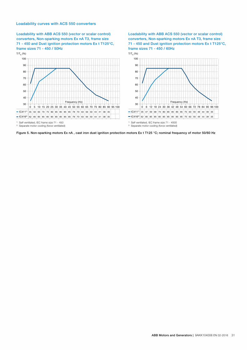
Loadability with ABB ACS 550 (vector or scalar control) converters, Non-sparking motors Ex nA T3, frame size 71 - 450 and Dust ignition protection motors Ex t T125°C, frame sizes 71 - 450 / 50Hz
100
90
80
70
60
50
40
30 0 5 10 15 20 25 30 35 40 45 50 55 60 65 70 75 80 85 90 95 100
IC4111) 35 50 65 70 75 80 85 85 85 85 78 70 63 56 50 44 41 38 35
IC4162) 62 85 85 85 85 85 85 85 85 85 78 70 63 56 50 44 41 38 35
1) Self ventilated, IEC frame size 71 - 4502) Separate motor cooling (force ventilated)
Frequency (Hz)
T/TN (%)
Loadability with ABB ACS 550 (vector or scalar control) converters, Non-sparking motors Ex nA T3, frame size 71 - 450 and Dust ignition protection motors Ex t T125°C, frame sizes 71 - 450 / 60Hz
0 6 12 18 24 30 36 42 48 54 60 66 72 78 84 90 96 100
IC4111) 35 47 59 68 74 80 85 85 85 85 75 63 55 49 44 39 35
IC4162) 62 85 85 85 85 85 85 85 85 85 75 63 55 49 44 39 35
1) Self ventilated, IEC frame size 71 - 45002) Separate motor cooling (force ventilated)
Frequency (Hz)
100
90
80
70
60
50
40
30
T/TN (%)
Loadability curves with ACS 550 converters
Figure 5. Non-sparking motors Ex nA , cast iron dust ignition protection motors Ex t T125 °C; nominal frequency of motor 50/60 Hz
ABB Motors and Generators | 9AKK104006 EN 02-2016 31

32 9AKK104006 EN 02-2016 | ABB Motors and Generators
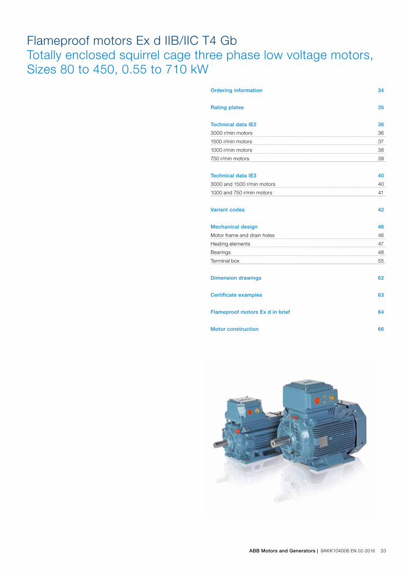
Flameproof motors Ex d IIB/IIC T4 GbTotally enclosed squirrel cage three phase low voltage motors, Sizes 80 to 450, 0.55 to 710 kW
Ordering information 34
Rating plates 35
Technical data IE2 36
3000 r/min motors 36
1500 r/min motors 37
1000 r/min motors 38
750 r/min motors 39
Technical data IE3 40
3000 and 1500 r/min motors 40
1000 and 750 r/min motors 41
Variant codes 42
Mechanical design 46
Motor frame and drain holes 46
Heating elements 47
Bearings 48
Terminal box 55
Dimension drawings 62
Certificate examples 63
Flameproof motors Ex d in brief 64
Motor construction 66
ABB Motors and Generators | 9AKK104006 EN 02-2016 33

When placing an order, specify motor type, size and product code according to the following example.
Positions 1 - 4
3GJP: Totally enclosed frameproof motor E xd with cast iron frame
Positions 5 and 6
IEC size
08: 80
09: 90
10: 100
11: 112
13: 132
16: 160
18: 180
20: 200
22: 225
25: 250
28: 280
31: 315
35: 355
40: 400
45: 450
Position 7
Speed (Pole pairs)
1: 2 poles
2: 4 poles
3: 6 poles
4: 8 poles
5: 10 poles
6: 12 poles
7: ≥ 12 poles
8: Two-speed motors
9: Multi-speed motors
Positions 8 to 10
Serial number
Position 11
- (Dash)
Position 12
Mounting arrangement
A: Foot-mounted, top-mounted terminal box
R: Foot-mounted, terminal box RHS seen from D-end
L: Foot-mounted, terminal box LHS seen from D-end
Ordering information
B: Flange-mounted, large flange with clearance holes
C: Flange-mounted, small flange with tapped holes
V: Flange-mounted, special flange
H: Foot/flange-mounted, large flange with clearance holes
J: Foot/flange-mounted, small flange with tapped holes
S: Foot/flange-mounted, terminal box RHS seen from D-end
T: Foot/flange-mounted, terminal box LHS seen from D-end
F: Foot/flange-mounted, special flange
Position 13
Voltage and frequency
Single-speed motors
B: 380 VΔ 50 Hz
D: 400 VΔ, 415 VΔ, 690 VY 50 Hz
E: 500 VΔ 50 Hz
F: 500 VY 50 Hz
S: 230 VΔ, 400 VY, 415 VY 50 Hz
T: 660 VΔ 50 Hz
U: 690 VΔ 50 Hz
X: Other rated voltage, connection or frequency, 690 V maximum
Position 14
Generation code G/H
Generation code is followed by variant codes according to the hazardous area, seen below and on corresponding pages with variant codes:
461 Ex d(e) design, Group IIC
The two bullets in the product code indicate choice of mounting arrangements, voltage and frequency code.
Efficiency values are given according to IEC 60034-2-1;2014.
Explanation of the product codeMotor type Motor size Product code Mounting arrangement code,
Voltage and frequency code,Generation code
Variant codes
M3JP 160MLA 3GJP 161 410 - ADH 002, etc. 1 2 3 4 5 6 7 8 9 10 11 12 13 14
Example
Motor type M3JP 160 MLA
Pole number 2
Mounting arrangement (IM-code) IM B3 (IM 1001)
Rated output 11 kW
Product code 3GJP161410-ADH
Variant codes if needed
34 9AKK104006 EN 02-2016 | ABB Motors and Generators

The rating plates are in table form giving values for speed, current and power factor for three voltages: 400V-415V-690V as standard. Other voltage and frequency combinations are possible and can be ordered with variant codes 002 or 209. Please see Variant code section.
Motor sizes 80 to 450
The following information will be shown on the motor rating plate:
− Lowest nominal efficiency at 100 %, 75 % and 50 % rated load
− Efficiency level − Year of manufacture − Type of protection − Apparatus group − Temperature class − Identification number of the certification body − Certificate number (both ATEX and IECEx are stamped
on the rating plate as standard)
M00
0737
Rating plates
Plates
ABB Motors and Generators | 9AKK104006 EN 02-2016 35

IP 55 - IC 411 - Insulation class F, temperature rise class BIE2 efficiency class according to IEC 60034-30-1; 2014
Technical data for Ex d IIB/IIC T4 GbFlameproof IE2 cast iron motors
Output kW Motor type Product code
Speed r/min
EfficiencyPower factor cosphi
Current Torque Moment of inertia J=1/4 GD2 kgm2
Weight kg
Sound pressure level LPA dB
Full load 100%
3/4 load 75%
1/2 load 50%
IN A
Is IN
TN Nm
Tl TN
Tb TN
3000 r/min = 2 poles 400 V 50 Hz CENELEC-design
0.75 M3JP 80MA 2 3GJP081310-••H 2877 80.7 80.2 76.5 0.85 1.54 7.1 2.4 4.0 4.6 0.0006 37 59
1.1 M3JP 80MB 2 3GJP081320-••H 2831 81.6 82.3 80.5 0.87 2.26 6.2 3.7 2.6 3.3 0.0007 39 59
1.5 M3JP 90SLA 2 3GJP091010-••H 2881 82.0 82.2 79.9 0.88 3.0 6.7 4.9 3.0 3.5 0.001 50 61
2.2 M3JP 90SLC 2 3GJP091030-••H 2877 83.7 84.3 83.0 0.89 4.2 7.8 7.3 2.7 3.5 0.0014 53 61
3 M3JP 100LA 2 3GJP101510-••H 2896 86.0 86.5 84.8 0.90 5.7 6.6 9.9 2.0 2.6 0.0036 70 65
4 M3JP 112MB 2 3GJP111320-••H 2891 86.0 87.0 87.0 0.89 7.59 6.9 13.2 2.0 3.0 0.0043 73 65
5.5 M3JP 132SMB 2 3GJP131220-••H 2905 87.0 86.4 84.4 0.89 10.5 6.8 17.99 2.6 3.4 0.009 101 71
7.5 M3JP 132SMD 2 3GJP131240-••H 2914 89.2 89.7 88.7 0.90 13.7 7.5 24.6 3.3 3.6 0.012 109 71
11 M3JP 160MLA 2 3GJP161410-••H 2931 90.1 90.4 89.3 0.89 20.2 6.7 35.81 2.5 3.2 0.043 213 71
15 M3JP 160MLB 2 3GJP161420-••H 2929 91.2 91.7 90.8 0.89 27.0 7.2 48.9 2.9 3.4 0.052 222 71
18.5 M3JP 160MLC 2 3GJP161430-••H 2934 91.6 92.4 92.3 0.90 32.4 7.4 60.3 3.1 3.5 0.062 233 69
22 M3JP 180MLA 2 3GJP181410-••H 2938 91.7 92.3 91.8 0.90 39.1 7.0 71.4 2.5 3.2 0.089 265 69
30 M3JP 200MLA 2 3GJP201410-••G 2956 93.2 93.6 93.0 0.88 52.7 7.4 96.9 3.0 3.2 0.15 310 74
37 M3JP 200MLC 2 3GJP201430-••G 2954 93.6 94.0 93.4 0.89 64.7 7.5 119.9 2.8 3.2 0.19 340 75
45 M3JP 225SMB 2 3GJP221220-••G 2968 93.8 93.9 93.0 0.87 78.8 7.2 144 2.7 3.0 0.26 400 76
55 M3JP 250SMA 2 3GJP251210-••G 2975 94.3 94.2 93.2 0.89 95.1 7.8 176 2.4 3.1 0.49 460 75
75 1) M3JP 280SMA 2 3GJP281210-••G 2977 94.3 93.8 92.2 0.88 131 7.6 240 2.1 3.0 0.8 625 77
90 1) M3JP 280SMB 2 3GJP281220-••G 2976 94.6 94.7 93.8 0.89 154 7.4 288 2.1 2.9 0.9 665 77
110 1) M3JP 315SMA 2 3GJP311210-••G 2982 94.9 94.4 92.9 0.86 197 7.4 352 2.2 3.2 1.2 980 78
132 1) M3JP 315SMB 2 3GJP311220-••G 2982 95.1 94.8 93.6 0.88 227 7.4 422 2.2 3.0 1.4 940 78
160 1) M3JP 315SMC 2 3GJP311230-••G 2981 95.4 95.2 94.2 0.89 271 7.5 512 2.3 3.0 1.7 1025 78
200 1) M3JP 315MLA 2 3GJP311410-••G 2980 95.7 95.7 94.9 0.90 335 7.7 640 2.6 3.0 2.1 1190 78
250 1) M3JP 355SMA 2 3GJP351210-••G 2984 95.7 95.5 94.5 0.89 423 7.7 800 2.1 3.3 3.0 1600 83
315 1) M3JP 355SMB 2 3GJP351220-••G 2980 95.7 95.6 95.0 0.89 531 7.0 1009 2.1 3.0 3.4 1680 83
355 1) M3JP 355SMC 2 3GJP351230-••G 2984 95.7 95.7 94.9 0.88 603 7.2 1136 2.2 3.0 3.6 1940 83
400 1) M3JP 355MLA 2 3GJP351410-••G 2982 96.9 96.6 95.9 0.88 677 7.1 1280 2.3 2.9 4.1 2190 83
450 1) M3JP 355MLB 2 3GJP351420-••G 2983 97.1 97.0 96.4 0.90 743 7.9 1440 2.2 2.9 4.3 2270 83
500 1) M3JP 355LKA 2 3GJP351810-••G 2982 96.9 96.9 96.5 0.90 827 7.5 1601 2.0 3.9 4.8 2510 83
560 3) M3JP 400LA 2 3GJP401510-••G 2988 97.2 97.2 96.6 0.89 934 7.8 1789 2.5 3.7 7.9 3230 82
560 3) M3JP 400LKA 2 3GJP401810-••G 2988 97.2 97.2 96.6 0.89 934 7.8 1789 2.5 3.7 7.9 3230 82
630 3) M3JP 400LB 2 3GJP401520-••G 2987 97.4 97.2 96.7 0.89 1049 7.6 2014 2.6 3.7 8.2 3330 82
630 3) M3JP 400LKB 2 3GJP401820-••G 2987 97.4 97.2 96.7 0.89 1049 7.6 2014 2.6 3.7 8.2 3330 82
710 3) M3JP 400LC 2 3GJP401530-••G 2987 97.5 97.4 96.9 0.89 1178 7.2 2270 2.6 3.4 9.3 3580 82
710 3) M3JP 400LKC 2 3GJP401830-••G 2987 97.5 97.4 96.9 0.89 1178 7.2 2270 2.6 3.4 9.3 3580 82
3000 r/min = 2 poles 400 V 50 Hz High-output design
9.2 2) M3JP 132SME 2 3GJP131250-••H 2875 86.9 88.2 87.9 0.91 16.9 6.0 30.6 2.6 2.9 0.012 109 71
22 2) M3JP 160MLD 2 3GJP161440-••H 2929 91.2 91.9 91.4 0.90 38.3 7.5 71.7 3.1 3.3 0.07 239 77
30 M3JP 180MLB 2 3GJP181420-••H 2943 92.5 93.2 92.6 0.90 52.2 7.1 97.23 2.3 3.2 0.13 298 78
37 M3JP 180MLC 2 3GJP181430-••H 2950 92.8 93.1 92.8 0.90 64.9 8.1 119.9 3.3 3.7 0.13 298 77
45 M3JP 200MLE 2 3GJP201450-••G 2945 93.3 93.5 93.1 0.88 79.4 7.3 146 2.9 3.1 0.22 345 79
55 M3JP 225SMC 2 3GJP221230-••G 2965 93.9 94.2 93.5 0.88 95.8 7.1 177 2.6 3.0 0.29 420 80
67 4) M3JP 225SMD 2 3GJP221240-••G 2966 93.9 93.9 93.0 0.86 120 7.4 215 2.8 3.2 0.31 430 78
75 M3JP 250SMB 2 3GJP251220-••G 2969 93.8 93.9 93.2 0.89 129 7.9 241 2.6 3.1 0.57 500 80
90 4) M3JP 250SMC 2 3GJP251230-••G 2965 94.4 94.5 93.9 0.89 153 7.7 289 2.5 3.0 0.59 510 80
110 1) M3JP 280SMC 2 3GJP281230-••G 2978 95.1 95.1 94.5 0.90 186 7.9 352 2.4 3.0 1.15 725 77
1) 3dB(A) sound pressure level reduction with unidirectional fan construction. Direction of rotation must be stated when ordering, see variant codes 044 and 0452) Efficiency class IE13) Unidirectional fan construction as standard. Direction of rotation must be stated when ordering, see variant codes 044 and 0454) For 400-415 V 50 Hz ( 380 V 50 Hz voltage code B )
36 9AKK104006 EN 02-2016 | ABB Motors and Generators

1) Temperature rise class F2) Efficiency class IE1
IP 55 - IC 411 - Insulation class F, temperature rise class BIE2 efficiency class according to IEC 60034-30-1; 2014
Technical data for Ex d IIB/IIC T4 GbFlameproof IE2 cast iron motors
Output kW Motor type Product code
Speed r/min
EfficiencyPower factor cosphi
Current Torque Moment of inertia J=1/4 GD2 kgm2
Weight kg
Sound pressure level LPA dB
Full load 100%
3/4 load 75%
1/2 load 50%
IN A
Is IN
TN Nm
Tl TN
Tb TN
1500 r/min = 4 poles 400 V 50 Hz CENELEC-design
0.55 2) M3JP 80MA 4 3GJP082310-••H 1421 76.6 76.9 74.1 0.73 1.49 4.7 3.7 2.2 2.7 0.001 38 59
0.75 M3JP 80MB 4 3GJP082320-••H 1416 80.2 80.1 77.5 0.75 1.87 5.4 5.0 2.7 3.1 0.0012 40 59
1.1 M3JP 90SLA 4 3GJP092010-••H 1432 82.2 82.1 79.6 0.77 2.5 6.5 7.3 3.0 3.5 0.002 51 54
1.5 M3JP 90SLC 4 3GJP092030-••H 1431 83.2 83.6 81.9 0.78 3.3 6.6 10.0 3.3 3.7 0.003 53 54
2.2 M3JP 100LA 4 3GJP102510-••H 1437 85.5 86.5 85.8 0.84 4.4 5.9 14.6 2.3 3.0 0.0075 70 52
3 M3JP 100LB 4 3GJP102520-••H 1444 86.5 87.5 86.8 0.83 6.1 6.4 19.9 2.7 3.4 0.0081 72 59
4 M3JP 112MC 4 3GJP112330-••H 1458 88.2 87.7 85.4 0.78 8.6 9.2 26.3 3.4 4.9 0.013 81 61
5.5 M3JP 132SMB 4 3GJP132220-••H 1458 89.5 89.2 87.3 0.80 11.7 7.9 36.0 3.7 3.8 0.023 111 60
7.5 M3JP 132SMD 4 3GJP132240-••H 1460 89.2 89.0 87.3 0.76 16.7 8.4 49.2 4.0 3.9 0.034 114 60
11 M3JP 160MLC 4 3GJP162430-••H 1470 91.2 91.3 90.0 0.82 21.5 8.0 71.5 3.3 3.8 0.096 232 62
15 M3JP 160MLE 4 3GJP162450-••H 1467 92.0 92.3 91.8 0.84 28.5 8.0 97.7 3.3 3.2 0.13 255 61
18.5 M3JP 180MLA 4 3GJP182410-••H 1474 91.6 92.1 91.5 0.83 35.7 7.2 120 2.6 3.1 0.19 277 62
22 M3JP 180MLB 4 3GJP182420-••H 1474 92.2 92.5 91.9 0.82 42.0 7.7 142 2.8 3.4 0.23 296 62
30 M3JP 200MLB 4 3GJP202420-••G 1471 92.5 93.2 93.1 0.84 55.0 7.4 194 3.0 2.8 0.34 340 61
37 M3JP 225SMB 4 3GJP222220-••G 1480 93.6 93.9 93.4 0.85 69.0 7.6 239 3.2 2.9 0.42 390 67
45 M3JP 225SMC 4 3GJP222230-••G 1477 94.1 94.4 94.3 0.86 78.4 7.6 291 3.2 2.7 0.49 425 67
55 M3JP 250SMA 4 3GJP252210-••G 1479 94.7 94.7 94.1 0.84 100 7.2 355 2.5 3.1 0.72 415 66
75 M3JP 280SMA 4 3GJP282210-••G 1484 94.5 94.7 94.4 0.85 134 6.9 482 2.5 2.8 1.25 625 68
90 M3JP 280SMB 4 3GJP282220-••G 1483 94.7 95.0 94.5 0.85 160 7.2 579 2.5 2.7 1.5 765 68
110 M3JP 315SMA 4 3GJP312210-••G 1487 95.1 95.1 94.3 0.86 194 7.2 706 2.3 2.8 2.3 900 70
132 M3JP 315SMB 4 3GJP312220-••G 1487 95.4 95.4 94.7 0.86 232 7.1 847 2.3 2.7 2.6 960 70
160 M3JP 315SMC 4 3GJP312230-••G 1487 95.3 95.3 94.8 0.85 284 7.2 1027 2.4 2.9 2.9 1000 70
200 M3JP 315MLA 4 3GJP312410-••G 1486 95.6 95.6 95.3 0.86 351 7.2 1285 2.5 2.9 3.5 1160 70
250 M3JP 355SMA 4 3GJP352210-••G 1488 95.9 96.0 95.5 0.85 442 7.1 1604 2.3 2.7 5.9 1610 74
315 M3JP 355SMB 4 3GJP352220-••G 1488 95.9 96.2 95.8 0.86 550 7.3 2021 2.3 2.8 6.9 1780 74
355 M3JP 355SMC 4 3GJP352230-••G 1487 95.9 96.2 95.9 0.87 614 6.8 2279 2.4 2.7 7.2 2010 78
400 M3JP 355MLA 4 3GJP352410-••G 1489 96.3 96.3 95.9 0.85 705 6.8 2565 2.3 2.6 8.4 2330 78
450 M3JP 355MLB 4 3GJP352420-••G 1490 96.7 96.7 96.1 0.86 780 6.9 2884 2.3 2.9 8.4 2330 78
500 M3JP 355LKA 4 3GJP352810-••G 1490 97.0 97.0 96.5 0.86 865 6.8 3204 2.0 3.0 10 2690 78
560 M3JP 400LA 4 3GJP402510-••G 1491 96.8 96.8 96.3 0.85 982 7.4 3586 2.4 2.8 15 3200 78
560 M3JP 400LKA 4 3GJP402810-••G 1491 96.8 96.8 96.3 0.85 982 7.4 3586 2.4 2.8 15 3200 78
630 M3JP 400LB 4 3GJP402520-••G 1491 97.0 97.0 96.5 0.87 1077 7.6 4034 2.2 2.9 16 3580 78
630 M3JP 400LKB 4 3GJP402820-••G 1491 97.0 97.0 96.5 0.87 1077 7.6 4034 2.2 2.9 16 3580 78
710 1) M3JP 400LC 4 3GJP402530-••G 1491 97.1 97.1 96.7 0.86 1227 7.6 4547 2.4 3.0 17 3680 78
710 1) M3JP 400LKC 4 3GJP402830-••G 1491 97.1 97.1 96.7 0.86 1227 7.6 4547 2.4 3.0 17 3680 78
1500 r/min = 4 poles 400 V 50 Hz High-output design
9.2 2) M3JP 132SME 4 3GJP132250-••H 1446 88.4 89.2 88.1 0.80 18.7 6.0 60.7 2.7 3.0 0.034 114 60
18.5 M3JP 160MLF 4 3GJP162460-••H 1469 91.8 92.2 91.6 0.84 35.0 8.2 120 3.5 3.8 0.13 255 68
22 2) M3JP 160MLG 4 3GJP162470-••H 1466 90.8 91.1 90.3 0.81 43.9 8.3 143 2.9 3.9 0.13 255 68
30 2) M3JP 180MLC 4 3GJP182430-••H 1466 92.1 92.4 91.8 0.81 59.6 7.6 195 2.2 3.3 0.248 304 66
37 M3JP 200MLC 4 3GJP202430-••G 1475 93.0 93.1 92.4 0.82 70.5 7.5 239 3.5 3.2 0.34 340 73
55 M3JP 225SMD 4 3GJP222240-••G 1483 94.3 94.4 93.9 0.83 101 7.4 354 3.4 2.9 0.55 445 68
60 2) M3JP 225SME 4 3GJP222250-••G 1477 93.6 93.7 92.9 0.84 110 8.0 387 3.6 3.0 0.55 445 74
75 2) M3JP 250SMB 4 3GJP252220-••G 1476 93.8 94.2 93.9 0.86 135 7.0 485 2.6 2.9 0.88 505 73
86 M3JP 250SMC 4 3GJP252230-••G 1477 94.9 95.3 95.0 0.85 155 7.8 556 2.9 3.5 0.98 495 74
110 M3JP 280SMC 4 3GJP282230-••G 1485 95.1 95.4 95.1 0.86 193 7.6 707 3.0 3.0 1.85 725 68
ABB Motors and Generators | 9AKK104006 EN 02-2016 37

IP 55 - IC 411 - Insulation class F, temperature rise class BIE2 efficiency class according to IEC 60034-30-1; 2014
Technical data for Ex d IIB/IIC T4 GbFlameproof IE2 cast iron motors
1) Temperature rise class F2) Efficiency class IE1
Output kW Motor type Product code
Speed r/min
EfficiencyPower factor cosphi
Current Torque Moment of inertia J=1/4 GD2 kgm2
Weight kg
Sound pressure level LPA dB
Full load 100%
3/4 load 75%
1/2 load 50%
IN A
Is IN
TN Nm
Tl TN
Tb TN
1000 r/min = 6 poles 400 V 50 Hz CENELEC-design
0.37 M3JP 80MA 6 3GJP083310-••H 952 71.6 68.4 61.4 0.58 1.28 4.6 3.7 3.5 3.9 0.0022 38 50
0.55 2) M3JP 80MB 6 3GJP083320-••H 938 70.3 68.1 61.8 0.65 1.73 4.2 5.5 2.7 3.1 0.0022 38 50
0.75 M3JP 90SLA 6 3GJP093010-••H 946 79.2 78.2 74.1 0.64 2.1 5.5 7.6 3.1 3.6 0.0037 52 44
1.1 M3JP 90SLC 6 3GJP093030-••H 938 78.5 77.9 74.3 0.70 3.1 4.6 11.3 2.7 3.0 0.0048 53 44
1.5 M3JP 100LA 6 3GJP103510-••H 951 81.6 81.4 78.8 0.72 3.7 5.3 15.1 2.2 3.0 0.012 69 54
2.2 M3JP 112MB 6 3GJP113320-••H 950 82.5 82.2 79.4 0.72 5.5 5.0 22.1 2.1 2.8 0.014 72 54
3 M3JP 132SMB 6 3GJP133220-••H 961 84.0 84.3 82.5 0.75 6.8 6.0 29.8 1.9 3.2 0.032 105 57
4 M3JP 132SMC 6 3GJP133230-••H 967 85.7 85.6 83.6 0.75 9.3 6.3 39.5 2.1 3.4 0.034 107 57
5.5 M3JP 132SMD 6 3GJP133240-••H 967 87.5 87.7 86.2 0.72 12.7 7.2 54.3 2.3 3.6 0.039 109 62
7.5 M3JP 160MLA 6 3GJP163410-••H 965 87.6 88.6 88.3 0.78 15.8 6.4 74.2 1.7 2.9 0.126 253 65
11 M3JP 160MLB 6 3GJP163420-••H 972 90.1 91.0 90.4 0.81 22.1 6.9 108 2.4 3.5 0.126 253 65
15 M3JP 180MLB 6 3GJP183420-••H 973 90.5 91.0 90.5 0.82 29.7 6.8 147 1.8 3.0 0.25 304 58
18.5 M3JP 200MLA 6 3GJP203410-••G 983 90.5 90.9 90.2 0.82 36.2 7.1 179 3.2 3.1 0.37 300 66
22 M3JP 200MLB 6 3GJP203420-••G 983 91.6 92.0 91.5 0.82 42.8 7.5 213 3.2 3.2 0.43 320 61
30 M3JP 225SMB 6 3GJP223220-••G 985 92.2 92.7 92.4 0.82 57.9 7.4 290 3.4 3.0 0.64 385 61
37 M3JP 250SMA 6 3GJP253210-••G 990 93.4 93.8 93.3 0.81 70.6 6.5 357 2.4 3.1 1.16 455 6645 M3JP 280SMA 6 3GJP283210-••G 990 93.4 93.8 93.5 0.83 83.8 7.0 434 2.5 2.5 1.85 705 66
55 M3JP 280SMB 6 3GJP283220-••G 990 93.8 94.2 93.9 0.84 100 7.0 530 2.7 2.6 2.2 645 66
75 M3JP 315SMA 6 3GJP313210-••G 992 94.4 94.4 93.5 0.82 139 7.4 721 2.4 2.8 3.2 830 70
90 M3JP 315SMB 6 3GJP313220-••G 992 94.8 94.7 94.1 0.84 166 7.5 866 2.4 2.8 4.1 930 70
110 M3JP 315SMC 6 3GJP313230-••G 991 95.0 95.0 94.6 0.83 201 7.4 1059 2.5 2.9 4.9 1100 70
132 M3JP 315MLA 6 3GJP313410-••G 991 95.3 95.4 94.9 0.83 240 7.5 1271 2.7 3.0 5.8 1150 68
160 M3JP 355SMA 6 3GJP353210-••G 993 95.4 95.6 95.2 0.83 291 7.0 1538 2.0 2.6 7.9 1520 75
200 M3JP 355SMB 6 3GJP353220-••G 993 95.7 95.9 95.7 0.83 364 7.2 1923 2.2 2.7 9.7 1680 75
250 M3JP 355SMC 6 3GJP353230-••G 993 95.7 95.8 95.4 0.82 460 7.4 2404 2.6 2.9 11.3 1820 75
315 M3JP 355MLB 6 3GJP353420-••G 992 95.7 96.0 95.5 0.83 570 7.0 3032 2.5 2.7 13.5 2180 75
355 M3JP 355LKA 6 3GJP353810-••G 992 95.7 95.9 95.4 0.81 658 7.6 3417 2.7 2.9 15.5 2690 75
400 M3JP 400LA 6 3GJP403510-••G 993 96.2 96.2 95.6 0.82 731 7.1 3846 2.3 2.7 17 3180 76
400 M3JP 400LKA 6 3GJP403810-••G 993 96.2 96.2 95.6 0.82 731 7.1 3846 2.3 2.7 17 3180 76
450 M3JP 400LB 6 3GJP403520-••G 994 96.6 96.6 96.1 0.82 819 7.4 4323 2.4 2.8 20.5 3430 76
450 M3JP 400LKB 6 3GJP403820-••G 994 96.6 96.6 96.1 0.82 819 7.4 4323 2.4 2.8 20.5 3430 76
500 M3JP 400LC 6 3GJP403530-••G 993 96.6 96.5 96.1 0.83 891 7.2 4809 2.5 2.7 22 3580 76
500 M3JP 400LKC 6 3GJP403830-••G 993 96.6 96.5 96.1 0.83 891 7.2 4809 2.5 2.7 22 3580 76
560 M3JP 400LD 6 3GJP403540-••G 993 96.9 96.9 96.4 0.85 984 7.4 5386 2.4 2.8 24 3680 77
560 M3JP 400LKD 6 3GJP403840-••G 993 96.9 96.9 96.4 0.85 984 7.4 5386 2.4 2.8 24 3680 77
630 M3JP 450LA 6 3GJP453510-••G 994 96.7 96.7 96.3 0.84 1127 6.5 6053 1.1 2.5 31 4320 81
1000 r/min = 6 poles 400 V 50 Hz High-output design
14 1) 2) M3JP 160MLC 6 3GJP163430-••H 969 89.2 89.5 88.5 0.75 30.1 7.5 138 2.8 4.0 0.126 253 64
18.5 2) M3JP 180MLC 6 3GJP183430-••H 971 90.1 90.1 88.5 0.74 41.2 7.3 181 2.5 3.7 0.25 304 61
30 2) M3JP 200MLC 6 3GJP203430-••G 983 90.6 90.8 89.6 0.81 59.3 7.5 291 3.5 3.4 0.49 340 65
37 2) M3JP 225SMC 6 3GJP223230-••G 983 91.8 92.1 92.2 0.83 69.6 7.1 359 3.0 2.8 0.75 415 64
45 M3JP 250SMB 6 3GJP253220-••G 986 93.1 93.4 93.2 0.84 84.0 7.2 435 3.3 2.8 1.49 500 65
75 M3JP 280SMC 6 3GJP283230-••G 990 94.2 94.7 94.5 0.84 137 7.3 723 2.8 2.7 2.85 725 66
38 9AKK104006 EN 02-2016 | ABB Motors and Generators

IP 55 - IC 411 - Insulation class F, temperature rise class BIE2 efficiency class according to IEC 60034-30-1; 2014
Technical data for Ex d IIB/IIC T4 GbFlameproof IE2 cast iron motors
Output kW Motor type Product code
Speed r/min
EfficiencyPower factor cosphi
Current Torque Moment of inertia J=1/4 GD2 kgm2
Weight kg
Sound pressure level LPA dB
Full load 100%
3/4 load 75%
1/2 load 50%
IN A
Is IN
TN Nm
Tl TN
Tb TN
750 r/min = 8 poles 400 V 50 Hz CENELEC-design
0.18 M3JP 80MA 8 3GJP084310-••H 720 57.7 52.0 43.4 0.42 1.15 3.3 2.4 3.7 4.0 0.0022 38 36
0.25 M3JP 80MB 8 3GJP084320-••H 705 61.4 57.2 49.5 0.51 1.21 3.2 3.4 2.6 2.8 0.0022 38 36
0.37 M3JP 90SLA 8 3GJP094010-••H 697 65.5 63.7 57.6 0.63 1.33 3.0 5.1 2.0 2.2 0.0036 50 36
0.55 M3JP 90SLC 8 3GJP094030-••H 695 68.7 67.7 63.2 0.61 2.0 3.0 7.5 2.2 2.4 0.0037 52 36
0.75 M3JP 100LA 8 3GJP104510-••H 720 76.5 74.1 68.3 0.54 2.7 4.2 9.9 2.4 3.1 0.012 69 54
1.1 M3JP 100LB 8 3GJP104520-••H 717 76.4 74.9 70.2 0.57 3.6 3.7 14.6 2.1 2.9 0.012 69 54
1.5 M3JP 112MC 8 3GJP114330-••H 713 75.3 73.3 67.6 0.54 5.4 3.4 20.1 2.0 3.2 0.014 73 54
2.2 M3JP 132SMC 8 3GJP134230-••H 720 80.3 79.2 75.4 0.65 6.1 4.5 29.1 1.7 2.7 0.034 107 59
3 2) M3JP 132SMD 8 3GJP134240-••H 711 79.9 80.3 78.1 0.71 8.0 4.1 40.4 1.5 2.8 0.036 109 59
4 M3JP 160MLA 8 3GJP164410-••H 722 83.3 84.7 84.2 0.70 10.3 4.7 52.9 1.6 2.6 0.133 251 59
5.5 M3JP 160MLB 8 3GJP164420-••H 723 86.8 87.2 86.0 0.71 13.5 5.8 72.7 1.9 3.1 0.133 251 53
7.5 1) 2) M3JP 160MLC 8 3GJP164430-••H 718 82.0 84.0 84.0 0.70 19.3 5.7 99.8 2.1 2.9 0.133 251 55
11 M3JP 180MLB 8 3GJP184420-••H 723 88.3 89.2 88.7 0.72 25.5 5.6 145 2.0 3.0 0.245 298 63
15 M3JP 200MLA 8 3GJP204410-••G 734 89.9 90.4 89.5 0.79 30.6 6.9 195 2.4 3.2 0.45 315 56
18.5 M3JP 225SMA 8 3GJP224210-••G 734 90.0 90.7 90.2 0.74 39.2 6.1 240 2.2 3.0 0.61 370 55
22 M3JP 225SMB 8 3GJP224220-••G 732 90.6 91.4 91.2 0.81 45.3 6.5 287 1.9 2.9 0.68 350 56
30 M3JP 250SMA 8 3GJP254210-••G 735 91.6 91.0 90.5 0.79 60.7 6.7 389 2.0 2.9 1.25 420 56
37 M3JP 280SMA 8 3GJP284210-••G 742 92.7 92.9 92.2 0.79 72.6 7.3 476 1.7 3.0 1.85 605 65
45 M3JP 280SMB 8 3GJP284220-••G 741 93.2 93.4 92.8 0.78 89.2 7.6 579 1.8 3.1 2.2 645 65
55 M3JP 315SMA 8 3GJP314210-••G 742 93.4 93.9 93.4 0.79 106 7.1 707 1.6 2.7 3.2 830 62
75 M3JP 315SMB 8 3GJP314220-••G 741 93.7 93.8 93.7 0.82 146 7.1 966 1.7 2.7 4.1 930 62
90 M3JP 315SMC 8 3GJP314230-••G 741 94.0 94.3 94.0 0.82 170 7.4 1159 1.8 2.7 4.9 1000 64
110 M3JP 315MLA 8 3GJP314410-••G 740 94.0 94.2 94.3 0.83 211 7.3 1419 1.8 2.7 5.8 1150 72
132 M3JP 355SMA 8 3GJP354210-••G 744 94.7 94.6 94.2 0.80 256 7.5 1694 1.5 2.6 7.9 1520 69
160 M3JP 355SMB 8 3GJP354220-••G 744 95.2 95.2 94.8 0.77 293 7.6 1926 1.6 2.6 9.7 1680 69
200 M3JP 355SMC 8 3GJP354230-••G 742 95.3 95.7 95.5 0.79 385 7.4 2576 1.6 2.6 11.3 1930 69
250 M3JP 355MLB 8 3GJP354420-••G 743 95.4 95.5 95.0 0.80 472 7.5 3213 1.6 2.7 13.5 2370 72
315 M3JP 400LA 8 3GJP404510-••G 743 96.1 96.0 95.6 0.81 592 7.0 4043 1.2 2.6 17 3180 71
315 M3JP 400LKA 8 3GJP404810-••G 743 96.1 96.0 95.6 0.81 592 7.0 4043 1.2 2.6 17 3180 71
355 M3JP 400LB 8 3GJP404520-••G 743 96.2 96.3 96.1 0.83 641 6.8 4562 1.2 2.5 21 3480 71
355 M3JP 400LKB 8 3GJP404820-••G 743 96.2 96.3 96.1 0.83 641 6.8 4562 1.2 2.5 21 3480 71
400 M3JP 400LC 8 3GJP404530-••G 744 96.3 96.4 96.1 0.82 735 7.4 5134 1.3 2.7 24 3680 71
400 M3JP 400LKC 8 3GJP404830-••G 744 96.3 96.4 96.1 0.82 735 7.4 5134 1.3 2.7 24 3680 71
450 M3JP 450LA 8 3GJP454510-••G 744 96.2 96.5 96.2 0.83 813 6.0 5775 1.0 2.5 26 3920 80
500 M3JP 450LB 8 3GJP454520-••G 744 96.3 96.4 96.2 0.83 902 6.4 6417 1.0 2.6 29 4160 80
560 M3JP 450LC 8 3GJP454530-••G 744 96.4 96.5 96.1 0.82 1038 7.0 7188 1.2 2.9 35 4520 80
630 1) M3JP 450LD 8 3GJP454540-••G 745 96.6 96.7 96.2 0.81 1162 7.6 8075 1.3 3.2 41 4960 80
750 r/min = 8 poles 400 V 50 Hz High-output design
18.5 M3JP 200MLB 8 3GJP204420-••G 734 89.2 89.8 88.8 0.80 37.1 6.9 240 2.2 3.2 0.54 335 57
30 M3JP 225SMC 8 3GJP224230-••G 731 90.7 91.6 91.6 0.78 61.2 6.3 391 2.3 3.0 0.75 410 59
37 M3JP 250SMB 8 3GJP254220-••G 737 92.2 92.9 92.5 0.79 73.0 7.5 479 2.3 3.4 1.52 500 59
55 M3JP 280SMC 8 3GJP284230-••G 741 93.4 93.7 93.6 0.80 107 7.9 708 1.9 3.1 2.85 725 65
1) Temperature rise class F2) Efficiency class IE1
ABB Motors and Generators | 9AKK104006 EN 02-2016 39

IP 55 - IC 411 - Insulation class F, temperature rise class BIE3 efficiency class according to IEC 60034-30-1; 2014
Technical data for Ex d IIB/IIC T4 GbFlameproof IE3 cast iron motors
Output kW Motor type Product code
Speed r/min
EfficiencyPower factor cosphi
Current Torque Moment of inertia J=1/4 GD2 kgm2
Weight kg
Sound pressure level LPA dB
Full load 100%
3/4 load 75%
1/2 load 50%
IN A
Is IN
TN Nm
Tl TN
Tb TN
3000 r/min = 2 poles 400 V 50 Hz CENELEC-design
11 M3JP 160MLA 2 3GJP161410-••L 2943 91.2 92.0 91.6 0.91 19.1 7.2 35.6 2.6 3.6 0.057 225 69
15 M3JP 160MLB 2 3GJP161420-••L 2947 91.9 92.2 91.8 0.88 26.5 8.2 48.5 3.2 4.2 0.063 232 69
18.5 M3JP 160MLC 2 3GJP161430-••L 2949 92.4 93.0 92.6 0.90 32.0 9.0 59.8 3.3 3.9 0.076 246 73
22 M3JP 180MLA 2 3GJP181410-••L 2956 92.7 93.1 92.7 0.90 37.7 7.8 71.0 3.4 3.8 0.110 282 73
30 M3JP 200MLA 2 3GJP201410-••L 2957 93.3 93.8 93.6 0.88 52.4 7.5 96.9 2.5 3.1 0.182 332 73
37 M3JP 200MLB 2 3GJP201420-••L 2960 93.7 94.2 94.1 0.89 64.2 8.2 119.5 3.1 3.4 0.222 359 73
45 M3JP 225SMA 2 3GJP221210-••L 2968 94.0 94.0 93.0 0.87 79.6 7.3 144.8 3.2 3.1 0.296 405 76
55 M3JP 250SMA 2 3GJP251210-••L 2968 94.3 93.7 93.6 0.89 94.8 6.8 177 2.4 3.0 0.426 470 76
75 M3JP 280SMB 2 3GJP281220-••L 2978 94.7 94.4 93.5 0.88 130 7.0 240 2.3 3.0 0.90 766 74
90 M3JP 280SMC 2 3GJP281230-••L 2975 95.0 95.0 94.2 0.88 158 6.4 289 2.1 2.8 0.99 795 74
110 M3JP 315SMB 2 3GJP311220-••L 2982 95.2 94.9 93.9 0.87 192 7.0 352 1.8 2.7 1.3 1008 78
132 M3JP 315SMC 2 3GJP311230-••L 2982 95.4 95.4 94.6 0.87 229 6.8 422 2.0 2.8 1.5 1063 78
160 M3JP 315SMD 2 3GJP311240-••L 2983 95.6 95.6 94.9 0.87 275 7.4 512 2.2 2.8 1.7 1120 78
200 M3JP 315MLA 2 3GJP311410-••L 2983 95.8 95.8 95.3 0.88 342 7.7 640 2.5 3.1 2.1 1190 81
250 M3JP 355SMA 2 3GJP351210-••L 2985 95.8 95.6 94.6 0.89 423 7.7 800 2.1 3.3 3.0 1790 83
315 M3JP 355SMB 2 3GJP351220-••L 2980 95.8 95.7 95.0 0.89 529 7.0 1009 2.1 3.0 3.4 1870 83
355 M3JP 355SMC 2 3GJP351230-••L 2984 95.8 95.8 95.0 0.88 605 7.2 1136 2.2 3.0 3.6 1940 83
3000 r/min = 2 poles 400 V 50 Hz High-output design
250 M3JP 315LKB 2 3GJP311820-••L 2983 95.8 96.0 95.5 0.90 419 7.7 800 2.5 3.3 2.9 1630 81
1500 r/min = 4 poles 400 V 50 Hz CENELEC-design
11 M3JP 160MLA 4 3GJP162410-••L 1477 91.4 91.8 91.1 0.82 21.1 7.6 71.3 2.6 3.3 0.110 240 61
15 M3JP 160MLB 4 3GJP162420-••L 1477 92.1 92.4 91.6 0.82 28.5 8.2 97.0 3.0 3.7 0.135 259 61
18.5 M3JP 180MLA 4 3GJP182410-••L 1481 92.6 93.2 92.9 0.83 34.9 7.2 119 2.8 3.0 0.219 291 60
22 M3JP 180MLB 4 3GJP182420-••L 1481 93.0 93.5 93.3 0.82 41.4 6.5 142 3.0 3.2 0.243 296 60
30 M3JP 200MLA 4 3GJP202410-••L 1483 93.6 93.8 93.4 0.84 54.8 7.5 193 2.7 3.2 0.385 360 63
37 M3JP 225SMA 4 3GJP222210-••L 1482 93.9 94.1 93.8 0.83 68.9 7.2 239 3.1 3.1 0.427 394 67
45 M3JP 225SMB 4 3GJP222220-••L 1482 94.2 94.4 94.0 0.84 82.3 8.0 290 3.2 3.5 0.525 431 66
55 M3JP 250SMA 4 3GJP252210-••L 1482 94.6 94.7 94.0 0.84 100 7.1 354 2.9 3.4 0.694 442 68
75 M3JP 280SMB 4 3GJP282220-••L 1485 95.0 95.2 94.8 0.86 133 6.4 483 2.3 2.8 1.38 749 75
90 M3JP 280SMC 4 3GJP282230-••L 1485 95.2 95.5 95.2 0.86 158 7.1 578 2.5 2.9 1.73 809 75
110 M3JP 315SMB 4 3GJP312220-••L 1489 95.4 95.5 94.9 0.84 195 7.0 705 2.1 3.0 2.43 1026 71
132 M3JP 315SMC 4 3GJP312230-••L 1488 95.6 95.9 95.5 0.86 231 6.7 847 2.2 2.9 2.9 1099 71
160 M3JP 315SMD 4 3GJP312240-••L 1488 95.8 96.0 95.8 0.85 282 6.9 1026 2.2 3.0 3.2 1139 71
200 M3JP 315MLB 4 3GJP312420-••L 1487 96.0 96.4 96.4 0.86 351 6.8 1284 2.4 3.0 3.9 1312 74
250 M3JP 355SMA 4 3GJP352210-••L 1491 96.0 96.0 95.6 0.86 435 6.4 1601 2.1 2.9 5.9 1791 78
315 M3JP 355SMB 4 3GJP352220-••L 1491 96.0 96.1 95.7 0.85 550 7.3 2018 2.4 3.3 6.9 1959 78
355 M3JP 355SMC 4 3GJP352230-••L 1490 96.0 96.2 95.8 0.86 616 6.3 2273 2.3 2.8 7.2 1999 78
1500 r/min = 4 poles 400 V 50 Hz High-output design
250 M3JP 315LKA 4 3GJP312810-••L 1488 96.0 96.3 96.1 0.85 442 6.9 1604 2.5 3.2 4.4 1500 78
40 9AKK104006 EN 02-2016 | ABB Motors and Generators
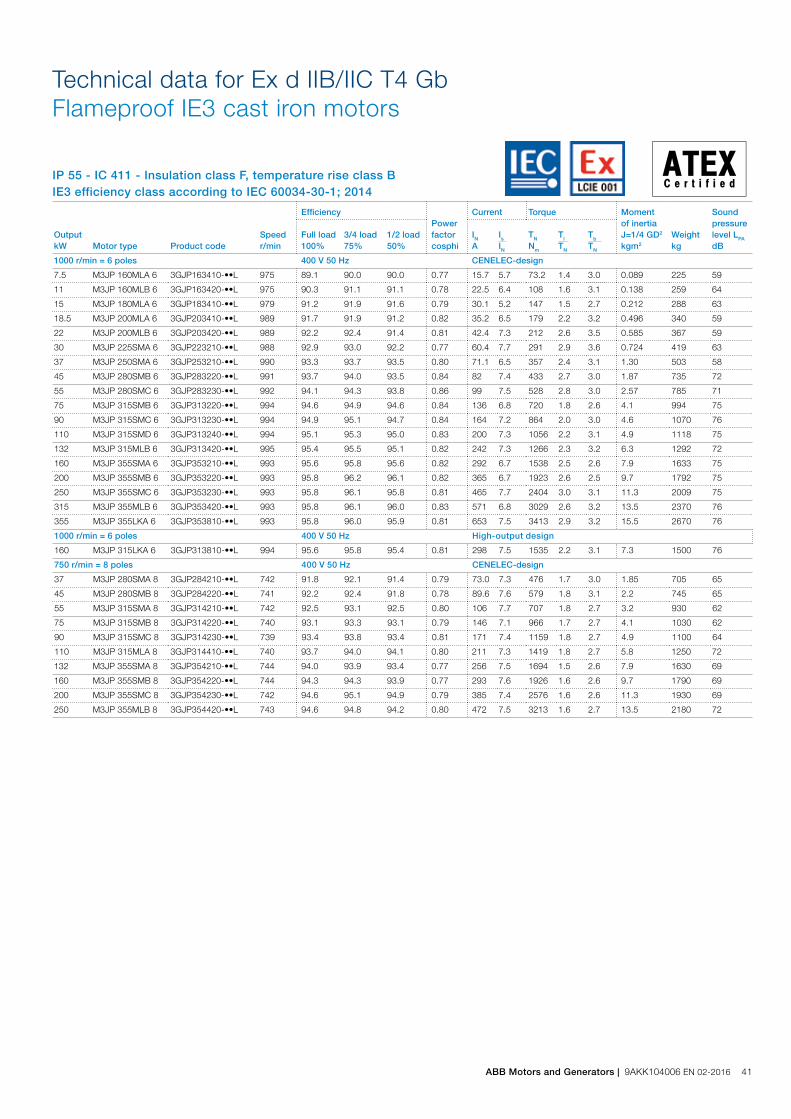
IP 55 - IC 411 - Insulation class F, temperature rise class BIE3 efficiency class according to IEC 60034-30-1; 2014
Technical data for Ex d IIB/IIC T4 GbFlameproof IE3 cast iron motors
Output kW Motor type Product code
Speed r/min
EfficiencyPower factor cosphi
Current Torque Moment of inertia J=1/4 GD2 kgm2
Weight kg
Sound pressure level LPA dB
Full load 100%
3/4 load 75%
1/2 load 50%
IN A
Is IN
TN Nm
Tl TN
Tb TN
1000 r/min = 6 poles 400 V 50 Hz CENELEC-design
7.5 M3JP 160MLA 6 3GJP163410-••L 975 89.1 90.0 90.0 0.77 15.7 5.7 73.2 1.4 3.0 0.089 225 59
11 M3JP 160MLB 6 3GJP163420-••L 975 90.3 91.1 91.1 0.78 22.5 6.4 108 1.6 3.1 0.138 259 64
15 M3JP 180MLA 6 3GJP183410-••L 979 91.2 91.9 91.6 0.79 30.1 5.2 147 1.5 2.7 0.212 288 63
18.5 M3JP 200MLA 6 3GJP203410-••L 989 91.7 91.9 91.2 0.82 35.2 6.5 179 2.2 3.2 0.496 340 59
22 M3JP 200MLB 6 3GJP203420-••L 989 92.2 92.4 91.4 0.81 42.4 7.3 212 2.6 3.5 0.585 367 59
30 M3JP 225SMA 6 3GJP223210-••L 988 92.9 93.0 92.2 0.77 60.4 7.7 291 2.9 3.6 0.724 419 63
37 M3JP 250SMA 6 3GJP253210-••L 990 93.3 93.7 93.5 0.80 71.1 6.5 357 2.4 3.1 1.30 503 58
45 M3JP 280SMB 6 3GJP283220-••L 991 93.7 94.0 93.5 0.84 82 7.4 433 2.7 3.0 1.87 735 72
55 M3JP 280SMC 6 3GJP283230-••L 992 94.1 94.3 93.8 0.86 99 7.5 528 2.8 3.0 2.57 785 71
75 M3JP 315SMB 6 3GJP313220-••L 994 94.6 94.9 94.6 0.84 136 6.8 720 1.8 2.6 4.1 994 75
90 M3JP 315SMC 6 3GJP313230-••L 994 94.9 95.1 94.7 0.84 164 7.2 864 2.0 3.0 4.6 1070 76
110 M3JP 315SMD 6 3GJP313240-••L 994 95.1 95.3 95.0 0.83 200 7.3 1056 2.2 3.1 4.9 1118 75
132 M3JP 315MLB 6 3GJP313420-••L 995 95.4 95.5 95.1 0.82 242 7.3 1266 2.3 3.2 6.3 1292 72
160 M3JP 355SMA 6 3GJP353210-••L 993 95.6 95.8 95.6 0.82 292 6.7 1538 2.5 2.6 7.9 1633 75
200 M3JP 355SMB 6 3GJP353220-••L 993 95.8 96.2 96.1 0.82 365 6.7 1923 2.6 2.5 9.7 1792 75
250 M3JP 355SMC 6 3GJP353230-••L 993 95.8 96.1 95.8 0.81 465 7.7 2404 3.0 3.1 11.3 2009 75
315 M3JP 355MLB 6 3GJP353420-••L 993 95.8 96.1 96.0 0.83 571 6.8 3029 2.6 3.2 13.5 2370 76
355 M3JP 355LKA 6 3GJP353810-••L 993 95.8 96.0 95.9 0.81 653 7.5 3413 2.9 3.2 15.5 2670 76
1000 r/min = 6 poles 400 V 50 Hz High-output design
160 M3JP 315LKA 6 3GJP313810-••L 994 95.6 95.8 95.4 0.81 298 7.5 1535 2.2 3.1 7.3 1500 76
750 r/min = 8 poles 400 V 50 Hz CENELEC-design
37 M3JP 280SMA 8 3GJP284210-••L 742 91.8 92.1 91.4 0.79 73.0 7.3 476 1.7 3.0 1.85 705 65
45 M3JP 280SMB 8 3GJP284220-••L 741 92.2 92.4 91.8 0.78 89.6 7.6 579 1.8 3.1 2.2 745 65
55 M3JP 315SMA 8 3GJP314210-••L 742 92.5 93.1 92.5 0.80 106 7.7 707 1.8 2.7 3.2 930 62
75 M3JP 315SMB 8 3GJP314220-••L 740 93.1 93.3 93.1 0.79 146 7.1 966 1.7 2.7 4.1 1030 62
90 M3JP 315SMC 8 3GJP314230-••L 739 93.4 93.8 93.4 0.81 171 7.4 1159 1.8 2.7 4.9 1100 64
110 M3JP 315MLA 8 3GJP314410-••L 740 93.7 94.0 94.1 0.80 211 7.3 1419 1.8 2.7 5.8 1250 72
132 M3JP 355SMA 8 3GJP354210-••L 744 94.0 93.9 93.4 0.77 256 7.5 1694 1.5 2.6 7.9 1630 69
160 M3JP 355SMB 8 3GJP354220-••L 744 94.3 94.3 93.9 0.77 293 7.6 1926 1.6 2.6 9.7 1790 69
200 M3JP 355SMC 8 3GJP354230-••L 742 94.6 95.1 94.9 0.79 385 7.4 2576 1.6 2.6 11.3 1930 69
250 M3JP 355MLB 8 3GJP354420-••L 743 94.6 94.8 94.2 0.80 472 7.5 3213 1.6 2.7 13.5 2180 72
ABB Motors and Generators | 9AKK104006 EN 02-2016 41

Variant codesFlameproof motors, Ex d IIB/IIC T4 Gb
Frame size
Code/ Variants 80 90 100 112 132 160 180 200 225 250 280 315 355 400 450Administration
531 Sea freight packing • • • • • • • • • • • • • • •
532 Packing of motor in vertical mounting position - - - - - - - • • • • • - - -
533 Wooden sea freight packing • • • • • • • • • • • • • • •
590 Mounting of customer supplied part other than coupling. • • • • • • • • • • • • • • •
Balancing
417 Vibration acc. to Grade B (IEC 60034-14). • • • • • • • • • • • • • • •
423 Balanced without key. • • • • • • • • • • • • • • •
424 Full-key balancing • • • • • • • • • • • • • • •
Bearings and Lubrication
036 Transport lock for bearings. - - - - - • • • • • • • • • •
037 Roller bearing at D-end. - - - - - • • • • • • • - - -
040 Heat-resistant grease ○ ○ ○ ○ ○ • • • • • • • • • •
058 Angular contact bearing at D-end, shaft force away from bearing. - - - - - - - - - - • • • • •
107 Pt100 2-wire in bearings. - - - - - • • • • • • • • • •
128 Double PT100, 2-wire in bearings - - - - - • • • • • • • • • •
129 Double PT100, 3-wire in bearings - - - - - • • • • • • • • • •
130 Pt100 3-wire in bearings. - - - - - • • • • • • • • • •
194 2Z bearings greased for life at both ends. ○ ○ ○ ○ ○ • • • • • - - - - -
433 Outlet grease collector - - - - - - - - - - • • • • •
506 Nipples for vibration measurement: SKF Marlin Quick Connect stud CMSS-2600-3
- - - - - • • • • • • • • • •
593 Bearings grease suitable for food and beverage industry. • • • • • • • • • • • • • • •
654 Provision for vibration sensors (M8x1) - - - - - • • • • • • • • • •
795 Lubrication information plate - - - - - • • • • • ○ ○ ○ ○ ○
796 Grease nipples JIS B 1575 PT 1/8 Type A - - - - - • • • • • • • • • •
797 Stainless steel SPM nipples - - - - - • • • • • • • • • •
798 Stainless steel grease nipples - - - - - • • • • • • • • • •
799 Grease nipples flat type DIN 3404, thread M10x1 - - - - - • • • • • • • • • •
800 Grease nipples JIS B 1575 PT 1/8” pin type - - - - - • • • • • • • • • •
Branch standard designs
178 Stainless steel / acid proof bolts. ○ ○ ○ ○ ○ • • • • • • • • • •
204 Jacking bolts for foot mounted motors. - - - - - • • • • • • • ○ ○ ○
209 Non-standard voltage or frequency, (special winding). • • • • • • • • • • • • • • •
396 Motor designed for ambient temperature -20 °C to -40 °C, with space heaters (code 450/451 must be added)
• • • • • • • • • • • • • • -
397 Motor designed for ambient temperature -40 °C to -55 °C, with space heaters (code 450/451 must be added)
• • • • • • • • • • • • • • -
398 Motor designed for ambient temperature -20 °C to -40 °C • • • • • • • • • • • • • • -
399 Motor designed for ambient temperature -40 °C to -55 °C • • • • • • • • • • • • • • -
425 Corrosion protected stator and rotor core. ○ ○ ○ ○ ○ ○ ○ ○ ○ ○ • • • • •
524 Special run-out tolerances on flange and shaft for close coupled pump applications.
- - - - • • • • • • • • • - -
786 Special design shaft upwards (V3, V36, V6) for outdoor mounting. • • • • • • • • • • - - - - -
Cooling system
044 Unidirectional fan for reduced noise level. Rotation clockwise seen from D-end. Available only for 2-pole motors.
- - - - - - - - - - • • • • -
045 Unidirectional fan for reduced noise level. Rotation counter clockwise seen from D-end. Available only for 2-pole motors.
- - - - - - - - - - • • • • -
068 Light alloy metal fan • • • • • • • • • • • • • • •
183 Separate motor cooling (fan axial, N-end). - - - - - • • • • • • • • • •
Variant codes specify additional options and features to the standard motor. The desired features are listed as three-digit variant codes in the motor order. Note also that there are variants that cannot be used together
Most of the variant codes apply to IE2 and IE3 motors. However, confirm the availability of variants for IE3 motors with your ABB sales office before making an order.
○ Included as standard• Available as option- Not applicable
42 9AKK104006 EN 02-2016 | ABB Motors and Generators

Frame size
Code/ Variants 80 90 100 112 132 160 180 200 225 250 280 315 355 400 450206 Steel fan - - - - - • • • • • • • • • -
514 Separate motor cooling (fan on top) - - - - - - - - - - • • • • •
791 Stainless steel fan cover - - - - - - - - • • • • • • •
Coupling
035 Assembly of customer supplied coupling-half. - - - - - - - - - - • • • • •
Documentation
141 Binding dimension drawing. • • • • • • • • • • • • • • •
Drain holes
448 Draining holes with metal plugs. - - - - - • • • • • • • • • •
Earthing Bolt
525 External earthing bolts on motor feet • • • • • • • • • • • • • • •
Hazardous Environments
334 Ex t, Dust group III B T125C Db, IP6X (non-conductive dust) acc. IEC/EN60079-31.
• • • • • • • • • • • • • • •
336 Ex t, Dust group III C T125 Db, IP6X (conductive dust) acc. IEC/EN60079-31. • • • • • • • • • • • • • • •
461 Ex d(e) design, Group II C • • • • • • • • • • • • • • -
464 Alleinschutz’ design. Certification of flame proof motor and protection device together.
• • • • • • • • • • • - - - -
508 Exde from Exd. - - - - - • • - - - - - - - -
516 Ex i approved temperature detectors (Pt100) - - - - - • • • • • • • • • •
813 Thermistor-based surface temperature protection T4 for frequency convertor duty.
• • • • • • • • • • • • • • -
814 Ex t (DIP) motors, temperature class T 150C. • • • • • • • • • • • • • • •
816 Pt-100-based surface temperature protection T4 for frequency convertor duty. 3-wire system.
- - - - - • • • • • • • • • -
Heating elements
450 Heating element, 100-120 V • • • • • • • • • • • • • • •
451 Heating element, 200 - 240 V • • • • • • • • • • • • • • •
Insulation system
014 Winding insulation class H. • • • • • • • • • • • • • • •
405 Special winding insulation for frequency converter supply. • • • • • • • • • • • • • • •
Marine
024 Fulfilling Bureau Veritas (BV) requirements, with certificate. • • • • • • • • • • • • • • •
025 Fulfilling Det Norske Veritas (DNV) requirements, with certificate. • • • • • • • • • • • • • • •
026 Fulfilling Lloyds Register of Shipping (LR) requirements, with certificate. • • • • • • • • • • • • • • •
027 Fulfilling American Bureau of Shipping (ABS) requirements, with certificate. • • • • • • • • • • • • • • •
049 Fulfilling Germanischer Lloyd (GL) requirements, with certificate. • • • • • • • • • • • • • • •
050 Fulfilling Registro Italiano Navale (RINA) requirements, with certificate. • • • • • • • • • • • • • • •
051 Fulfilling Russian Maritime Register of Shipping (RS) requirements, with certificate.
• • • • • • • • • • • • • • •
096 Fulfilling Lloyds Register of Shipping (LR) requirements, without certificate (non-essential duty only)
• • • • • • • • • • • • • • •
186 Fulfilling Det Norske Veritas (DNV) requirements, without certificate (non-essential duty only)
• • • • • • • • • • • • • • •
481 Fulfilling Nippon Kaiji Kyokai (NK) requirements, with certificate. • • • • • • • • • • • • • • •
483 Fulfilling China Classification Societies (CCS) requirements (Beijing), with certificate.
• • • • • • • • • • • • • • •
484 Fulfilling Korea Register of Shipping (KR) requirements, with certificate. • • • • • • • • • • • • • • •
491 Fulfilling Nippon Kaiji Kyokai (NK) requirements, without certificate. • • • • • • • • • • • • • • •
492 Fulfilling Registro Italiano Navale (RINA) requirements, without certificate. • • • • • • • • • • • • • • •
493 Fulfilling China Classification Societies (CCS) requirements (Beijing), without certificate.
• • • • • • • • • • • • • • •
494 Fulfilling Korea Register of Shipping (KR) requirements, without certificate. • • • • • • • • • • • • • • •
496 Fulfilling Bureau Veritas (BV) requirements, without certificate(non-essential duty only)
• • • • • • • • • • • • • • •
675 Fulfilling American Bureau of Shipping (ABS) requirements, without certificate (non-essential duty only)
• • • • • • • • • • • • • • •
676 Fulfilling Germanischer Lloyd (GL) requirements, without certificate (non-essential duty only)
• • • • • • • • • • • • • • •
Mounting arrangements
007 IM 3001 flange mounted, IEC flange, from IM 1001 (B5 from B3). • • • • • - - - - - - - - - -
008 IM 2101 foot/flange mounted, IEC flange, from IM 1001 (B34 from B3). • • • • • - - - - - - - - - -
009 IM 2001 foot/flange mounted, IEC flange, from IM 1001 (B35 from B3). • • • • • • • • • • • • • • •
047 IM 3601 flange mounted, IEC flange, from IM 3001 (B14 from B5). • • • • • - - - - - - - - - -
○ Included as standard• Available as option- Not applicable
ABB Motors and Generators | 9AKK104006 EN 02-2016 43
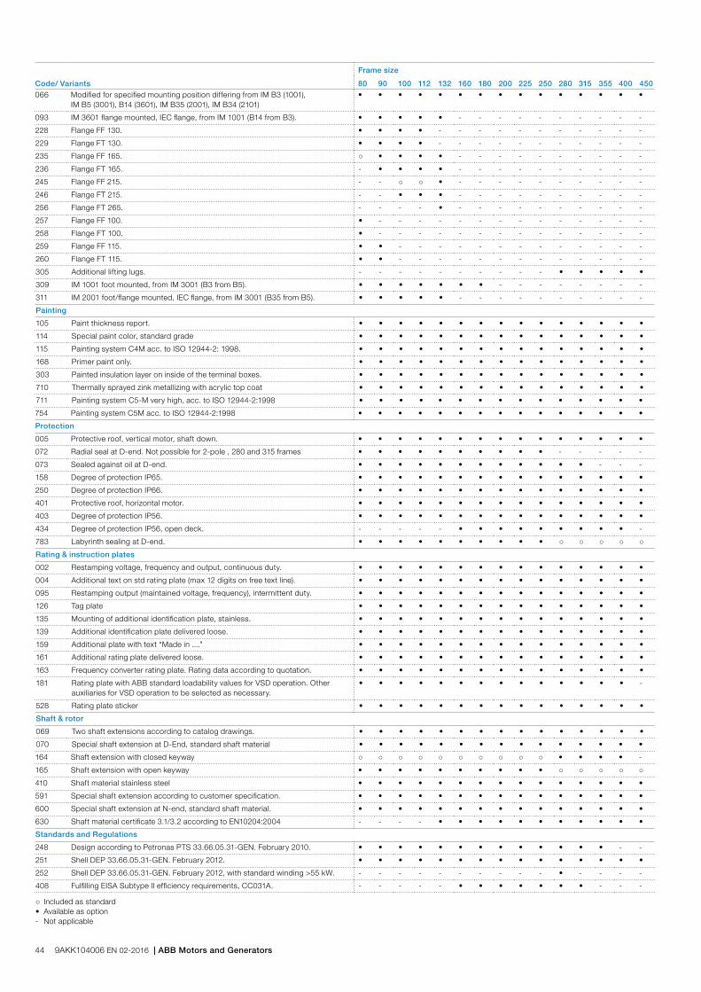
Frame size
Code/ Variants 80 90 100 112 132 160 180 200 225 250 280 315 355 400 450066 Modified for specified mounting position differing from IM B3 (1001),
IM B5 (3001), B14 (3601), IM B35 (2001), IM B34 (2101)• • • • • • • • • • • • • • •
093 IM 3601 flange mounted, IEC flange, from IM 1001 (B14 from B3). • • • • • - - - - - - - - - -
228 Flange FF 130. • • • • - - - - - - - - - - -
229 Flange FT 130. • • • • - - - - - - - - - - -
235 Flange FF 165. ○ • • • • - - - - - - - - - -
236 Flange FT 165. - • • • • - - - - - - - - - -
245 Flange FF 215. - - ○ ○ • - - - - - - - - - -
246 Flange FT 215. - - • • • - - - - - - - - - -
256 Flange FT 265. - - - - • - - - - - - - - - -
257 Flange FF 100. • - - - - - - - - - - - - - -
258 Flange FT 100. • - - - - - - - - - - - - - -
259 Flange FF 115. • • - - - - - - - - - - - - -
260 Flange FT 115. • • - - - - - - - - - - - - -
305 Additional lifting lugs. - - - - - - - - - - • • • • •
309 IM 1001 foot mounted, from IM 3001 (B3 from B5). • • • • • • • - - - - - - - -
311 IM 2001 foot/flange mounted, IEC flange, from IM 3001 (B35 from B5). • • • • • - - - - - - - - - -
Painting
105 Paint thickness report. • • • • • • • • • • • • • • •
114 Special paint color, standard grade • • • • • • • • • • • • • • •
115 Painting system C4M acc. to ISO 12944-2: 1998. • • • • • • • • • • • • • • •
168 Primer paint only. • • • • • • • • • • • • • • •
303 Painted insulation layer on inside of the terminal boxes. • • • • • • • • • • • • • • •
710 Thermally sprayed zink metallizing with acrylic top coat • • • • • • • • • • • • • • •
711 Painting system C5-M very high, acc. to ISO 12944-2:1998 • • • • • • • • • • • • • • •
754 Painting system C5M acc. to ISO 12944-2:1998 • • • • • • • • • • • • • • •
Protection
005 Protective roof, vertical motor, shaft down. • • • • • • • • • • • • • • •
072 Radial seal at D-end. Not possible for 2-pole , 280 and 315 frames • • • • • • • • • • - - - - -
073 Sealed against oil at D-end. • • • • • • • • • • • • - - -
158 Degree of protection IP65. • • • • • • • • • • • • • • •
250 Degree of protection IP66. • • • • • • • • • • • • • • •
401 Protective roof, horizontal motor. • • • • • • • • • • • • • • •
403 Degree of protection IP56. • • • • • • • • • • • • • • •
434 Degree of protection IP56, open deck. - - - - - • • • • • • • • • -
783 Labyrinth sealing at D-end. • • • • • • • • • • ○ ○ ○ ○ ○
Rating & instruction plates
002 Restamping voltage, frequency and output, continuous duty. • • • • • • • • • • • • • • •
004 Additional text on std rating plate (max 12 digits on free text line). • • • • • • • • • • • • • • •
095 Restamping output (maintained voltage, frequency), intermittent duty. • • • • • • • • • • • • • • •
126 Tag plate • • • • • • • • • • • • • • •
135 Mounting of additional identification plate, stainless. • • • • • • • • • • • • • • •
139 Additional identification plate delivered loose. • • • • • • • • • • • • • • •
159 Additional plate with text “Made in ....” • • • • • • • • • • • • • • •
161 Additional rating plate delivered loose. • • • • • • • • • • • • • • •
163 Frequency converter rating plate. Rating data according to quotation. • • • • • • • • • • • • • • •
181 Rating plate with ABB standard loadability values for VSD operation. Other auxiliaries for VSD operation to be selected as necessary.
• • • • • • • • • • • • • • -
528 Rating plate sticker • • • • • • • • • • • • • • •
Shaft & rotor
069 Two shaft extensions according to catalog drawings. • • • • • • • • • • • • • • •
070 Special shaft extension at D-End, standard shaft material • • • • • • • • • • • • • • •
164 Shaft extension with closed keyway ○ ○ ○ ○ ○ ○ ○ ○ ○ ○ • • • • -
165 Shaft extension with open keyway • • • • • • • • • • ○ ○ ○ ○ ○
410 Shaft material stainless steel • • • • • • • • • • • • • • •
591 Special shaft extension according to customer specification. • • • • • • • • • • • • • • •
600 Special shaft extension at N-end, standard shaft material. • • • • • • • • • • • • • • •
630 Shaft material certificate 3.1/3.2 according to EN10204:2004 - - - - • • • • • • • • • • •
Standards and Regulations
248 Design according to Petronas PTS 33.66.05.31-GEN. February 2010. • • • • • • • • • • • • • - -
251 Shell DEP 33.66.05.31-GEN. February 2012. • • • • • • • • • • • • • • •
252 Shell DEP 33.66.05.31-GEN. February 2012, with standard winding >55 kW. - - - - - - - - - - • - - - -
408 Fulfilling EISA Subtype II efficiency requirements, CC031A. - - - - - • • • • • • • - - -
○ Included as standard• Available as option- Not applicable
44 9AKK104006 EN 02-2016 | ABB Motors and Generators

Frame size
Code/ Variants 80 90 100 112 132 160 180 200 225 250 280 315 355 400 450540 China energy label • • • • • • • • • • • • • - -
541 Inmetro certification • • • • • • • • • • • • • • -
543 Australian MEPS • • • • • • • • • • • • • - -
544 Australian HE MEPS - - - - - • • • • • • • • - -
547 Certificate of conformity according TR-CU 012/2011 for customs union RU, KZ, BY.
• • • • • • • • • • • • • • •
782 Fulfilling CQST Certification requirements (China) • • • • • • • • • • • • • • -
Stator winding temperature sensors
121 Bimetal detectors, break type (NCC), (3 in series), 130 ºC, in stator winding • • • • • • • • • • • • • • •
122 Bimetal detectors, break type (NCC), (3 in series), 150 ºC, in stator winding • • • • • • • • • • • • • • •
123 Bimetal detectors, break type (NCC), (3 in series), 170 ºC, in stator winding - - - - - - - - - - • • • • •
125 Bimetal detectors, break type (NCC), (2x3 in series), 150 ºC, in stator winding • • • • • • • • • • • • • • •
127 Bimetal detectors, break type (NCC), (3 in series, 130 ºC & 3 in series, 150 ºC), in stator winding
• • • • • • • • • • • • • • •
328 PTC - thermistors (3 in series), 120ºC, in stator winding • • • • • • • • • • • • • • •
435 PTC - thermistors (3 in series), 130 ºC, in stator winding • • • • • • • • • • • • • • •
439 PTC - thermistors (2x3 in series), 150 ºC, in stator winding • • • • • • • • • • • • • • •
441 PTC - thermistors (3 in series, 130 ºC & 3 in series, 150 ºC), in stator winding • • • • • • • • • • • • • • •
445 Pt100 2-wire in stator winding, 1 per phase - - - - - • • • • • • • • • •
446 Pt100 2-wire in stator winding, 2 per phase - - - - - • • • • • • • • • •
502 Pt100 3-wire in stator winding, 1 per phase - - - - - • • • • • • • • • •
503 Pt100 3-wire in stator winding, 2 per phase - - - - - • • • • • • • • • •
511 PTC thermistors (2 x 3 in series), 130 ºC, in stator winding • • • • • • • • • • • • • • •
Terminal box
021 Terminal box LHS (seen from D-end). - - - - - • • - - - - - - - -
022 Cable entry LHS (seen from D-end). • • • • • • • • • • • • • • •
157 Terminal box degree of protection IP65. • • • • • • • • • • • • • • •
180 Terminal box RHS (seen from D-end). - - - - - • • - - - - - - - -
380 Separate terminal box for temperature detectors, std. material - - - - - • • • • • • • • • •
418 Separate terminal box for auxiliaries, standard material. - - - - - • • • • • • • • • •
466 Terminal box at N-end. - - - - - - - • • • • • • • •
468 Cable entry from D-end. • • • • • • • • • • • • - - -
469 Cable entry from N-end. • • • • • • • • • • • • - - -
553 Terminal box degree of protection IP66. • • • • • • • • • • • • • • •
568 Separate terminal box for heating elements, std. material - - - - - • • • • • • • • • •
730 Prepared for NPT cable glands. • • • • • • • • • • • • • • •
734 Standard cable gland, Ex d IIC, armoured cable. • • • • • • • • • • • • • • •
735 Standard cable gland, Ex d IIC, non-armoured cable. • • • • • • • • • • • • • • •
Testing
145 Type test report from a catalogue motor, 400V 50Hz. • • • • • • • • • • • • • • •
146 Type test with report for one motor from specific delivery batch. • • • • • • • • • • • • • • •
148 Routine test report. • • • • • • • • • • • • • • •
150 Customer witnessed testing. Specify test procedure with other codes. • • • • • • • • • • • • • • •
222 Torque/speed curve, type test and multi-point load test with report for one motor from specific delivery batch.
• • • • • • • • • • • • • • •
560 Shaft voltage test. • • • • • • • • • • • • • • •
561 Overspeed test. • • • • • • • • • • • • • • •
562 Overvoltage test. • • • • • • • • • • • • • • •
760 Vibration level test • • • • • • • • • • • • • • •
761 Vibration spectrum test for one motor from specific delivery batch. • • • • • • • • • • • • • • •
762 Noise level test for one motor from specific delivery batch. • • • • • • • • • • • • • • •
763 Noise spectrum test for one motor from specific delivery batch. - - - - - • • • • • • • • • •
764 Test for one motor from specific delivery batch with ABB frequency converter available at ABB test field. ABB standard test procedure.
• • • • • • • • • • • • • • •
Variable speed drives
479 Mounting of other type of pulse tacho with shaft extension, tacho not included. - - - - - • • • • • • • • • •
680 2048 pulse tacho, Ex d, tD, L&L 841910001 - - - - - • • • • • • • • • •
701 Insulated bearing at N-end. - - - - - - - - - - • • • • •
747 1024 pulse tacho, Ex d, tD, L&L 841910002 - - - - - • • • • • • • • • •
○ Included as standard• Available as option- Not applicable
ABB Motors and Generators | 9AKK104006 EN 02-2016 45
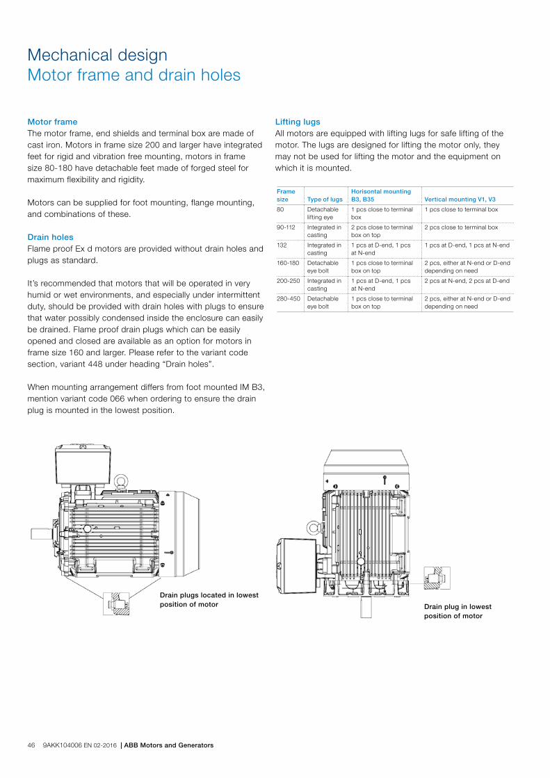
Mechanical designMotor frame and drain holes
Motor frameThe motor frame, end shields and terminal box are made of cast iron. Motors in frame size 200 and larger have integrated feet for rigid and vibration free mounting, motors in frame size 80-180 have detachable feet made of forged steel for maximum flexibility and rigidity.
Motors can be supplied for foot mounting, flange mounting, and combinations of these.
Drain holesFlame proof Ex d motors are provided without drain holes and plugs as standard.
It’s recommended that motors that will be operated in very humid or wet environments, and especially under intermittent duty, should be provided with drain holes with plugs to ensure that water possibly condensed inside the enclosure can easily be drained. Flame proof drain plugs which can be easily opened and closed are available as an option for motors in frame size 160 and larger. Please refer to the variant code section, variant 448 under heading “Drain holes”.
When mounting arrangement differs from foot mounted IM B3, mention variant code 066 when ordering to ensure the drain plug is mounted in the lowest position.
Drain plugs located in lowest position of motor
Lifting lugsAll motors are equipped with lifting lugs for safe lifting of the motor. The lugs are designed for lifting the motor only, they may not be used for lifting the motor and the equipment on which it is mounted.
Frame size Type of lugs
Horisontal mounting B3, B35 Vertical mounting V1, V3
80 Detachable lifting eye
1 pcs close to terminal box
1 pcs close to terminal box
90-112 Integrated in casting
2 pcs close to terminal box on top
2 pcs close to terminal box
132 Integrated in casting
1 pcs at D-end, 1 pcs at N-end
1 pcs at D-end, 1 pcs at N-end
160-180 Detachable eye bolt
1 pcs close to terminal box on top
2 pcs, either at N-end or D-end depending on need
200-250 Integrated in casting
1 pcs at D-end, 1 pcs at N-end
2 pcs at N-end, 2 pcs at D-end
280-450 Detachable eye bolt
1 pcs close to terminal box on top
2 pcs, either at N-end or D-end depending on need
Drain plug in lowest position of motor
46 9AKK104006 EN 02-2016 | ABB Motors and Generators

Heating elements
Heating elements are installed on stator winding coil heads to keep the winding free of corrosion in humid conditions. The power of the heating elements is shown in the table. You can order heating elements with variant code 450 or 451.
Motor size 80 90 100 112 132 160 180
Power (W) 25 25 25 25 25 25 25
Motor size 200 225 250 280 315 355 400 450
Power (W) 25 60 60 60 2x60 2x60 2x60 2x100
Motors for marine applications mounted on open deck may have heating element powers differing from the ones shown in this table.
ABB Motors and Generators | 9AKK104006 EN 02-2016 47

Bearings
ABB’s flame proof motors are normally fitted with single-rowdeep-groove grease lubricated ball bearings, as shown in the table below.
If the bearing at the D-end is replaced with a roller bearing (NU- or NJ-), higher radial forces can be handled. Roller bearings are suitable for belt-drive applications and can be ordered with variant code 037. Note that the possibility to have roller bearing at D-end is limited on larger flame proof motors due to the higher radial clearance in bearing and possible bending of shaft together with narrow flame path between shaft and inner bearing cover, especially in conjunction with gas group IIC design.
Motor size Number of poles
Standard design Alternative design
Deep groove ball bearings Roller bearings (037) Roller bearings (037) Angular contact ball bearing (058)
D-end N-end D-end, gas group IIB D-end, gas group IIC D-end
80 2 - 8 6205-2Z/C3 6204-2Z/C3 NA NA NA
90 2 - 8 6205-2Z/C3 6205-2Z/C3 NA NA NA
100 2 - 8 6206-2Z/C3 6206-2Z/C3 NA NA NA
112 2 - 8 6206-2Z/C3 6206-2Z/C3 NA NA NA
132 2 - 8 6208-2Z/C3 6208-2Z/C3 NA NA NA
160 2 - 12 6309/C3 6309/C3 NU 309 ECP/C3 NU 309 ECP/C3 NA
180 2 - 12 6310/C3 6310/C3 NU 310 ECP/C3 NU 310 ECP/C3 NA
200 2 6312M/C3 6310M/C3 NU 312 ECP/C3 NU 312 ECP/C3 NA
200 4 - 12 6312/C3 6310/C3 NU 312 ECP/C3 NU 312 ECP/C3 NA
225 2 6313M/C3 6312M/C3 NU 313 ECP/C3 NU 313 ECP/C3 NA
225 4 - 12 6313/C3 6312/C3 NU 313 ECP/C3 NU 313 ECP/C3 NA
250 2 6315M/C3 6313M/C3 NU 315 ECP/C3 NA NA
250 4 - 12 6315/C3 6313/C3 NU 315 ECP/C3 NA NA
280 2 6316/C3 6316/C3 1) NA 7316 B
4 - 12 6316/C3 6316/C3 NU 316 ECP/C3 NA 7316 B
315 2 6316/C3 6316/C3 1) NA 7316 B
4 - 12 6319/C3 6316/C3 NU 319 ECP/C3 NA 7319 B
355 2 6316M/C3 6316M/C3 NA NA 7316 B
4 - 12 6322/C3 6316/C3 NA NA 7322 B
400 2 6317M/C3 6317M/C3 NA NA 7317 B
4 - 12 6324/C3 6319/C3 NA NA 7324 B
450 4 - 12 6326M/C3 6322M/C3 NA NA 7326 B1) On request
Axially-locked bearingsAll motors with deep groove ball bearings are equipped as standard with an axially locked bearing at the D-end.
Transport lockingMotors with roller bearings or an angular-contact ball bearing are fitted with a transport lock before dispatch to prevent damage to bearings during transport. A warning label is attached to motors when transport locking is used.
Standard and alternative designs
When high axial forces are involved, angular-contact ball bearings should be used. When ordering a motor with an angular-contact ball bearing, specify also the method of mounting and the direction and magnitude of axial force to ensure that optimal bearing system design is chosen. The variant codes for ordering angular-contact ball bearings are 058 and 059.
Locking may also be fitted in other cases if severe transport conditions are expected.
Bearing sealsTable on next page present the standard and alternative and types of bearing seals per motor size.
48 9AKK104006 EN 02-2016 | ABB Motors and Generators
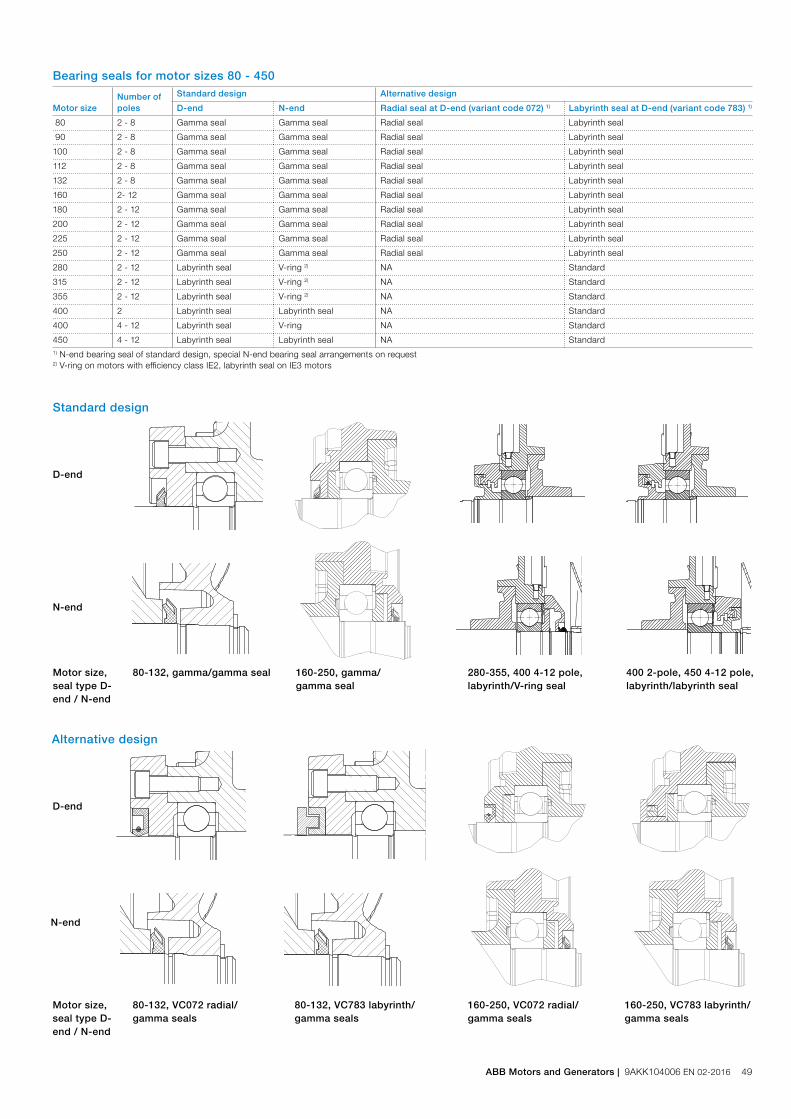
Standard design
Motor sizeNumber ofpoles
Standard design Alternative design
D-end N-end Radial seal at D-end (variant code 072) 1) Labyrinth seal at D-end (variant code 783) 1)
80 2 - 8 Gamma seal Gamma seal Radial seal Labyrinth seal
90 2 - 8 Gamma seal Gamma seal Radial seal Labyrinth seal
100 2 - 8 Gamma seal Gamma seal Radial seal Labyrinth seal
112 2 - 8 Gamma seal Gamma seal Radial seal Labyrinth seal
132 2 - 8 Gamma seal Gamma seal Radial seal Labyrinth seal
160 2- 12 Gamma seal Gamma seal Radial seal Labyrinth seal
180 2 - 12 Gamma seal Gamma seal Radial seal Labyrinth seal
200 2 - 12 Gamma seal Gamma seal Radial seal Labyrinth seal
225 2 - 12 Gamma seal Gamma seal Radial seal Labyrinth seal
250 2 - 12 Gamma seal Gamma seal Radial seal Labyrinth seal
280 2 - 12 Labyrinth seal V-ring 2) NA Standard
315 2 - 12 Labyrinth seal V-ring 2) NA Standard
355 2 - 12 Labyrinth seal V-ring 2) NA Standard
400 2 Labyrinth seal Labyrinth seal NA Standard
400 4 - 12 Labyrinth seal V-ring NA Standard
450 4 - 12 Labyrinth seal Labyrinth seal NA Standard1) N-end bearing seal of standard design, special N-end bearing seal arrangements on request2) V-ring on motors with efficiency class IE2, labyrinth seal on IE3 motors
D-end
N-end
Motor size,seal type D-end / N-end
80-132, gamma/gamma seal 160-250, gamma/gamma seal
280-355, 400 4-12 pole, labyrinth/V-ring seal
400 2-pole, 450 4-12 pole, labyrinth/labyrinth seal
Bearing seals for motor sizes 80 - 450
Alternative design
D-end
N-end
Motor size, seal type D-end / N-end
80-132, VC072 radial/gamma seals
80-132, VC783 labyrinth/gamma seals
160-250, VC072 radial/gamma seals
160-250, VC783 labyrinth/gamma seals
ABB Motors and Generators | 9AKK104006 EN 02-2016 49
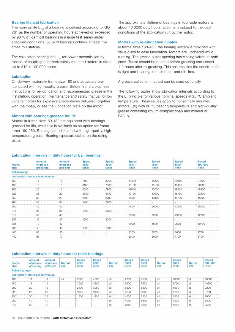
Bearing life and lubricationThe nominal life L10h of a bearing is defined according to ISO 281 as the number of operating hours achieved or exceeded by 90 % of identical bearings in a large test series under specified conditions. 50 % of bearings achieve at least five times this lifetime.
The calculated bearing life L10h for power transmission by means of coupling is for horizontally mounted motors in sizes up to 315 ≥ 100,000 hours.
LubricationOn delivery, motors in frame size 160 and above are pre-lubricated with high-quality grease. Before first start-up, see instructions for re-lubrication and recommended grease in the installation, operation, maintenance and safety manual for low voltage motors for explosive atmospheres delivered together with the motor, or see the lubrication plate on the motor.
Motors with bearings greased for lifeMotors in frame sizes 80-132 are equipped with bearings greased for life, while this is available as an option for frame sizes 160-250. Bearings are lubricated with high-quality, high-temperature grease. Bearing types are stated on the rating plate.
The approximate lifetime of bearings in four-pole motors is about 40 0000 duty hours. Lifetime is subject to the load conditions of the application run by the motor.
Motors with re-lubrication nipplesIn frame sizes 160-450, the bearing system is provided with valve discs to ease lubrication. Motors are lubricated while running. The grease outlet opening has closing valves at both ends. These should be opened before greasing and closed 1-2 hours after re-greasing. This ensures that the construction is tight and bearings remain dust- and dirt-free.
A grease-collection method can be used optionally.
The following tables show lubrication intervals according to the L1 principle for various nominal speeds in 25 °C ambient temperature. These values apply to horizontally mounted motors (B3) with 80 °C bearing temperature and high-quality grease containing lithium-complex soap and mineral or PAO-oil.
Lubrication intervals in duty hours for ball bearings
Amount Amount Speed Speed Speed Speed Speed SpeedFrame of grease of grease 3600 3000 1800 1500 1000 500-900size g/bearing g/N-end r/min r/min r/min r/min r/min r/min
Ball bearings
Lubrication intervals in duty hours
160 13 13 7100 8900 14300 16300 20500 21600
180 15 15 6100 7800 13100 15100 19400 20500
200 20 15 4300 5900 11000 13000 17300 18400
225 23 20 3600 5100 10100 12000 16400 17500
250 30 23 2400 3700 8500 10400 14700 15800
280 35 35 1900 3200 - - - -
280 40 40 - - 7800 9600 13900 15000
315 35 35 1900 3200 - - - -
315 55 40 - - 5900 7600 11800 12900
355 35 35 1900 3200 - - - -
355 70 40 - - 4000 5600 9600 10700
400 40 40 1500 2700 - - - -
400 85 55 - - 3200 4700 8600 9700
450 95 70 - - 2500 3900 7700 8700
Amount Amount Speed Speed Speed Speed Speed SpeedFrame of grease of grease Output 3600 3000 Output 1800 1500 Output 1000 Output 500-900size g/bearing g/N-end kW r/min r/min kW r/min r/min kW r/min kW r/min
Roller bearings
Lubrication intervals in duty hours
160 13 13 all 3600 4500 all 7200 8100 all 10300 all 10800
180 15 15 3000 3900 all 6600 7500 all 9700 all 10200
200 20 15 2100 3000 all 5500 6500 all 8600 all 9200
225 23 20 1800 1600 all 5100 6000 all 8200 all 8700
250 30 23 1200 1900 all 4200 5200 all 7300 all 7900
280 40 40 - - all 4000 5300 all 7000 all 8500
315 55 40 - - all 2900 3800 all 5900 all 6500
Lubrication intervals in duty hours for roller bearings
50 9AKK104006 EN 02-2016 | ABB Motors and Generators
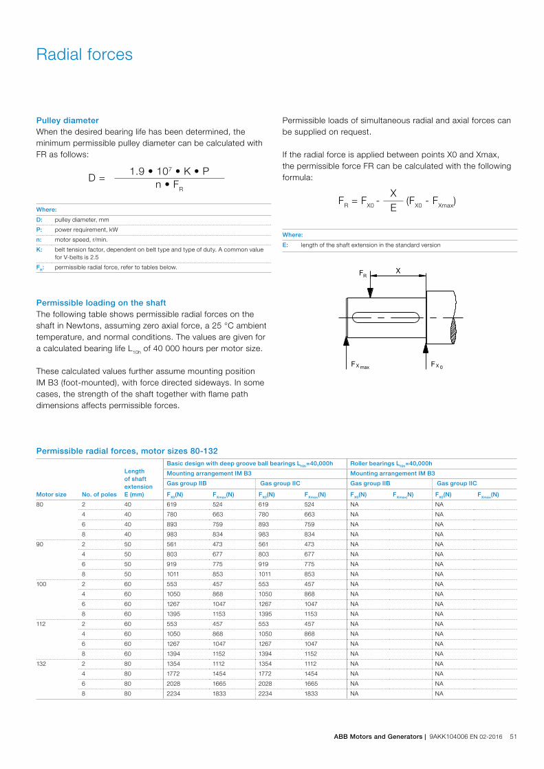
Radial forces
Pulley diameterWhen the desired bearing life has been determined, the minimum permissible pulley diameter can be calculated with FR as follows:
D =1.9 • 107 • K • P
n • FR
Where:
D: pulley diameter, mm
P: power requirement, kW
n: motor speed, r/min.
K: belt tension factor, dependent on belt type and type of duty. A common value for V-belts is 2.5
FR: permissible radial force, refer to tables below.
Permissible loading on the shaftThe following table shows permissible radial forces on the shaft in Newtons, assuming zero axial force, a 25 °C ambient temperature, and normal conditions. The values are given for a calculated bearing life L10h of 40 000 hours per motor size.
These calculated values further assume mounting position IM B3 (foot-mounted), with force directed sideways. In some cases, the strength of the shaft together with flame path dimensions affects permissible forces.
FR = FX0 -
X (FX0 - FXmax)E
Where:
E: length of the shaft extension in the standard version
Permissible radial forces, motor sizes 80-132
Permissible loads of simultaneous radial and axial forces can be supplied on request.
If the radial force is applied between points X0 and Xmax, the permissible force FR can be calculated with the following formula:
Motor size No. of poles
Length of shaft extension E (mm)
Basic design with deep groove ball bearings L10h=40,000h Roller bearings L10h=40,000h
Mounting arrangement IM B3 Mounting arrangement IM B3
Gas group IIB Gas group IIC Gas group IIB Gas group IIC
FX0(N) FXmax(N) FX0(N) FXmax(N) FX0(N) FXmax(N) FX0(N) FXmax(N)
80 2 40 619 524 619 524 NA NA
4 40 780 663 780 663 NA NA
6 40 893 759 893 759 NA NA
8 40 983 834 983 834 NA NA
90 2 50 561 473 561 473 NA NA
4 50 803 677 803 677 NA NA
6 50 919 775 919 775 NA NA
8 50 1011 853 1011 853 NA NA
100 2 60 553 457 553 457 NA NA
4 60 1050 868 1050 868 NA NA
6 60 1267 1047 1267 1047 NA NA
8 60 1395 1153 1395 1153 NA NA
112 2 60 553 457 553 457 NA NA
4 60 1050 868 1050 868 NA NA
6 60 1267 1047 1267 1047 NA NA
8 60 1394 1152 1394 1152 NA NA
132 2 80 1354 1112 1354 1112 NA NA
4 80 1772 1454 1772 1454 NA NA
6 80 2028 1665 2028 1665 NA NA
8 80 2234 1833 2234 1833 NA NA
ABB Motors and Generators | 9AKK104006 EN 02-2016 51

Permissible radial forces, motor sizes 160 to 450
Motor size Poles
Length of shaft extension E (mm)
Basic design with deep groove ball bearings L10h=40,000h Roller bearings L10h=40,000h
Mounting arrangement IM B3 Mounting arrangement IM B3
Gas group IIB Gas group IIC Gas group IIB Gas group IIC
FX0(N) FXmax(N) FX0(N) FXmax(N) FX0(N) FXmax(N) FX0(N) FXmax(N)
160 ML_ 2 110 2530 2120 2530 2120 6400 1800 6400 1800
4 110 3180 2670 3180 2670 7600 1800 7600 1800
6 110 3650 3040 3650 3040 7600 1800 7600 1800
8 110 4020 3040 4020 3040 7600 1800 7600 1800
180 ML_ 2 110 2900 2440 2900 2440 6970 2700 6970 2700
4 110 3660 3080 3660 3080 8500 2700 8500 2700
6 110 4190 3520 4190 3520 8500 2700 8500 2700
8 110 4620 3880 4620 3880 8500 2700 8500 2700
200 ML_ 2 110 3830 3150 3830 3150 9510 7000 9510 4200
4 110 4820 3980 4820 3980 11710 7000 11710 4200
6 110 5520 4550 5520 4550 13230 7000 13230 4200
8 110 6080 5000 6080 5000 14420 7000 14420 4200
225 SM_ 2 110 4350 3660 4350 3660 11650 7000 9300 3000
4 140 5490 2800 5490 2800 14340 7200 9300 2200
6 140 6280 2800 6280 2800 16190 7200 9300 2200
8 140 6920 2800 6920 2800 17300 7200 9300 2200
250 SM_ 2 140 5390 4350 5390 4350 15420 6700 NA
4 140 6790 5480 6790 5480 18980 9200 NA
6 140 7760 6270 3000 2800 21000 9200 NA
8 140 8550 6900 3000 2800 21000 9200 NA
280 SM_ 2 140 5835 4900 1) 16500 6000 NA
4 140 7360 6110 1) 20100 9200 NA
6 140 8425 6980 1) 22690 9200 NA
8 140 9165 7700 1) 24740 9200 NA
315 SM_ 2 140 5815 4960 1) 16540 6000 NA
4 170 9025 7470 1) 26590 9600 NA
6 170 10310 8530 1) 30030 10160 NA
8 170 11370 9410 1) 32740 10105 NA
315 ML_ 2 140 5855 5080 1) 16705 6205 NA
4 170 8980 7590 1) 26550 13705 NA
6 170 10255 8665 1) 29970 13710 NA
8 170 11335 9385 1) 32730 9945 NA
315 LK_ 2 140 5860 5195 1) 16885 6080 NA
4 170 9185 7945 1) 27225 13475 NA
6 170 10475 9060 1) 30735 13500 NA
355 SM_ 2 140 5790 5085 1) NA NA
4 210 11930 9890 1) NA NA
6 210 11930 9890 1) NA NA
8 210 11930 9890 1) NA NA
355 ML_ 2 140 5770 5120 1) NA NA
4 210 11980 10090 1) NA NA
6 210 11980 10090 1) NA NA
8 210 11980 10090 1) NA NA
355 LK_ 2 140 5500 5000 1) NA NA
4 210 12050 10450 1) NA NA
6 210 12050 10450 1) NA NA
8 210 12050 10450 1) NA NA
400 L_ 2 170 1) 1) NA NA
4 210 1) 1) NA NA
6 210 1) 1) NA NA
8 210 1) 1) NA NA
400 LK_ 2 170 1) 1) NA NA
4 210 1) 1) NA NA
6 210 1) 1) NA NA
8 210 1) 1) NA NA
450 L_ 4 210 1) 1) NA NA
6 210 1) 1) NA NA
8 210 1) 1) NA NA1) only allowed for direct coupling duty
52 9AKK104006 EN 02-2016 | ABB Motors and Generators

Axial forces
The following tables present permissible axial forces on the shaft in Newtons, assuming zero radial force, a 25 °C ambient temperature, and normal conditions. The values are given for a calculated bearing life of 20,000 and 40,000 hours per motor size.
At 60 Hz, the values must be reduced by 10 percent, and for two-speed motors, the higher speed determines permissible axial force. Permissible loads of simultaneous radial and axial forces can be supplied on request.
For axial force FAD, it is assumed that the D-bearing is locked with a locking ring.
Permissible axial forces, motor sizes 80-450
Ç
FAD
M00
0023
È
FAZFAD Æ
M00
0022
FAZ Å
Mounting arrangement IM B3 Mounting arrangement IM V1
Motor size PolesLength of shaft extension E (mm)
Mounting arrangement IM B3 Mounting arrangement IM V1
Deep groove ball bearings Deep groove ball bearings
L10 = 40,000 h L10 = 40,000 h
FAD(N) FAZ(N) FAD(N) FAZ(N)
80 2 40 660 300 690 280
4 40 820 460 860 440
6 40 940 580 970 550
8 40 1030 670 1070 650
90 2 50 740 220 780 190
4 50 900 380 950 340
6 50 1010 490 1080 450
8 50 1110 590 1170 540
100 2 60 1100 220 1180 170
4 60 1320 430 1430 360
6 60 1480 590 1600 510
8 60 1610 720 1730 640
112 2 60 1100 220 1180 170
4 60 1320 430 1430 360
6 60 1480 590 1600 510
8 60 1610 720 1730 640
132 2 80 1530 500 1700 390
4 80 1870 840 2080 690
6 80 2110 1080 2380 900
8 80 2320 1280 2580 1110
160 ML_ 2 110 2050 1435 2440 1155
4 110 2620 2005 3160 1635
6 110 3055 2440 3590 2060
8 110 3410 2790 3950 2430
180 ML_ 2 110 2570 1470 3075 1100
4 110 3230 2130 3975 1630
6 110 3730 2630 4420 2130
8 110 4140 3040 4890 2550
ABB Motors and Generators | 9AKK104006 EN 02-2016 53
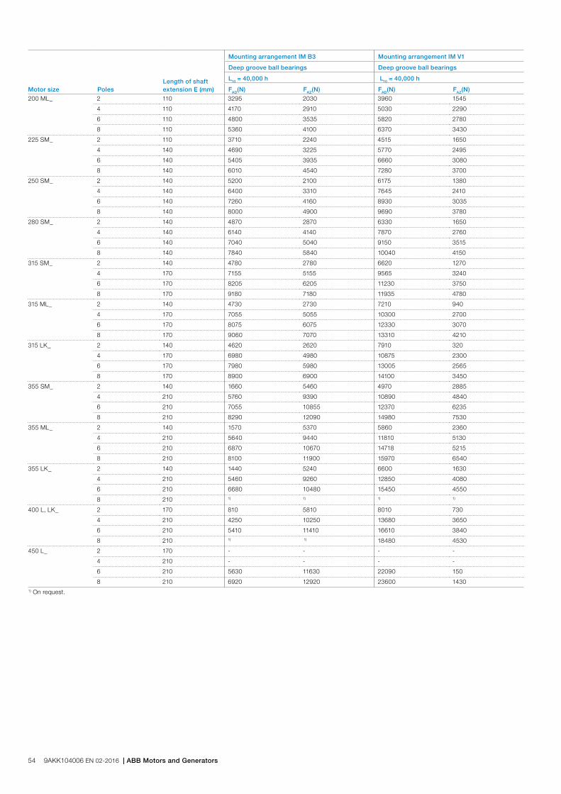
Motor size PolesLength of shaft extension E (mm)
Mounting arrangement IM B3 Mounting arrangement IM V1
Deep groove ball bearings Deep groove ball bearings
L10 = 40,000 h L10 = 40,000 h
FAD(N) FAZ(N) FAD(N) FAZ(N)
200 ML_ 2 110 3295 2030 3960 1545
4 110 4170 2910 5030 2290
6 110 4800 3535 5820 2780
8 110 5360 4100 6370 3430
225 SM_ 2 110 3710 2240 4515 1650
4 140 4690 3225 5770 2495
6 140 5405 3935 6660 3080
8 140 6010 4540 7280 3700
250 SM_ 2 140 5200 2100 6175 1380
4 140 6400 3310 7645 2410
6 140 7260 4160 8930 3035
8 140 8000 4900 9690 3780
280 SM_ 2 140 4870 2870 6330 1650
4 140 6140 4140 7870 2760
6 140 7040 5040 9150 3515
8 140 7840 5840 10040 4150
315 SM_ 2 140 4780 2780 6620 1270
4 170 7155 5155 9565 3240
6 170 8205 6205 11230 3750
8 170 9180 7180 11935 4780
315 ML_ 2 140 4730 2730 7210 940
4 170 7055 5055 10300 2700
6 170 8075 6075 12330 3070
8 170 9060 7070 13310 4210
315 LK_ 2 140 4620 2620 7910 320
4 170 6980 4980 10875 2300
6 170 7980 5980 13005 2565
8 170 8900 6900 14100 3450
355 SM_ 2 140 1660 5460 4970 2885
4 210 5760 9390 10890 4840
6 210 7055 10855 12370 6235
8 210 8290 12090 14980 7530
355 ML_ 2 140 1570 5370 5860 2360
4 210 5640 9440 11810 5130
6 210 6870 10670 14718 5215
8 210 8100 11900 15970 6540
355 LK_ 2 140 1440 5240 6600 1630
4 210 5460 9260 12850 4080
6 210 6680 10480 15450 4550
8 210 1) 1) 1) 1)
400 L, LK_ 2 170 810 5810 8010 730
4 210 4250 10250 13680 3650
6 210 5410 11410 16610 3840
8 210 1) 1) 18480 4530
450 L_ 2 170 - - - -
4 210 - - - -
6 210 5630 11630 22090 150
8 210 6920 12920 23600 14301) On request.
54 9AKK104006 EN 02-2016 | ABB Motors and Generators
Terminal boxStandard terminal box
Degree of protection and mounting optionsThe degree of protection for the standard terminal box is IP 55. It complies with the requirements of the type of protection ‘d’ flame proof and prevents the transmission of an internal explosion to the surrounding, potentially explosive atmosphere.
By default, terminal boxes are mounted on top of the motor at D-end. Side mounted terminal box is possible in frame sizes 160 and 180. Mounting at N-end is also possible for the larger frame sizes. Please refer to the variant code section for more details.
TurnabilityThe standard terminal boxes for motor sizes 80-250 can be turned 4*90°and in sizes 280-450 2*180° after delivery. For sizes 280-450 is also mounting of terminal box with opening towards D or N-end possible using the relevant variant codes when ordering.
Cable entriesTerminal box is provided as standard with tapped holes for cable glands as specified in table below. No cable glands are included as standard, the entry holes are closed with Ex d approved blanking plugs made of brass according table below. One tapped hole for main cables is closed with a plastic plug which is to be used for transport protection only. Different types of cable glands are available as option, suitable for either armoured and non-armoured cables, please refer to the Terminal box alternatives section for more details.
Cable type and terminationsTerminations are suitable for copper and aluminum cables (Al- cables on request for motor sizes 80 to 250). Cables are connected to terminals by cable lugs, which are not included in the delivery.
Earthing boltsThe motors are as standard provided with at least one earthing bolt inside the terminal box and another on the frame. The earthing bolt on the frame is located on top close to the terminal box for easy access from either side of the motor. As an option can also earting bolts on the feet be provided, please refer to variant code section.
OrderingTo ensure the delivery of desired terminations and cable entries for the motor, state the cable type, quantity, size, outer diameter and possibly type of cable glands needed when ordering. Modifying the cable entries on a flame proof terminal box is very difficult afterwards.
See section Variant codes for all options available.
ABB Motors and Generators | 9AKK104006 EN 02-2016 55

Standard deliveryStandard delivery if no other information is provided. Note: For other network voltages, contact your ABB sales office.
Cable entries for supply cablesMotor size Pole number Terminal box type
Amount and size of threaded holes Cable gland Ex d plug
Max. connectable core cross-section mm2/phase
Number and size of terminal bolts, 6 x
IE2 motors
80 - 90 2-8 25 1 x M25x1.5 - - 10 M5
100 - 132 2-8 25 2 x M32x1.5 - 1 x M32 10 M5
160 - 180 2-8 63 2 x M40x1.5 - 1 x M40 1x35 M6
200 - 250 2-8 160 2 x M50x1.5 - 1 x M50 1x70 M10
280 SM_ 2-8 210 2 x M63x1.5 - 1 x M63 2x150 M12
315 SM_, ML_ 2-8 370 2 x M75x1.5 - 1 x M75 2x240 M12
355 SMA - SMC 2-4 750 2 x M75x1.5 - 1 x M75 4x240 M12
355 SMA, SMB 6-8 370 2 x M75x1.5 - 1 x M75 2x240 M12
355 SMC 6 750 2 x M75x1.5 - 1 x M75 4x240 M12
355 SMC 8 370 2 x M75x1.5 - 1 x M75 2x240 M12
355 ML_, LK_ 2-8 750 2 x M75x1.5 - 1 x M75 4x240 M12
400 2-8 750 2 x M75x1.5 - 1 x M75 4x240 M12
450 6-8 750 2 x M75x1.5 - 1 x M75 4x240 M12
IE3 motors
160 - 180 2-8 63 2 x M40x1.5 - 1 x M40 1x35 M6
200 - 250 2-8 160 2 x M50x1.5 - 1 x M50 1x70 M10
280 2-8 210 2 x M75x1.5 - 1 x M75 2x150 M12
315 2-8 370 2 x M75x1.5 - 1 x M75 2x240 M12
355 SM_ 2-4 750 2 x M75x1.5 - 1 x M75 4x240 M12
355 SM_ 6 370 2 x M75x1.5 - 1 x M75 2x240 M12
355 ML_, LK_ 2-6 750 2 x M75x1.5 - 1 x M75 4x240 M12
Auxiliary cable entries
80 - 132 2-8 1 x M20x1.5 - 1xM20 1 x 2,5 mm2 per terminal
160-450 2-8 2 x M20x1.5 - 1xM20 1 x 2,5 mm2 per terminal
Motor size Earthing on frame Earthing in main terminal box
80 - 132 M6 M6
160 – 180 M6 M6
200 - 250 M8 M8
280 - 450 M10 2xM10
56 9AKK104006 EN 02-2016 | ABB Motors and Generators

To match the correct terminal box with motor size, find the motor type and correspondent terminal box type on the previous page. The box types and their dimensions are presented on this page.
Terminal boxTerminal box dimensions
Terminal box types acc. to current capacity A1 B1 H1
25 192 170 124
63 256 243 174
160 339 290 226
210 465 360 283
370 465 360 283
750 707 467 387
Motor sizes 80 to 132
Motor sizes 160 to 180
Motor sizes 200 to 250
M00
0203
Motor sizes 280 to 355
M00
0204
Motor sizes 355 to 450
M00
0366
M00
0366
M00
0735
M00
0367
Terminal boxes, standard with 6 terminals
ABB Motors and Generators | 9AKK104006 EN 02-2016 57
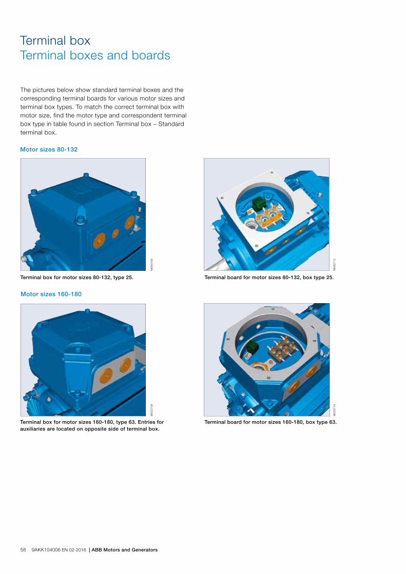
Terminal box for motor sizes 80-132, type 25.
Terminal box for motor sizes 160-180, type 63. Entries for auxiliaries are located on opposite side of terminal box.
M00
0708
M00
0709
Terminal board for motor sizes 80-132, box type 25.
M00
0713
Terminal board for motor sizes 160-180, box type 63.
M00
0714
The pictures below show standard terminal boxes and the corresponding terminal boards for various motor sizes and terminal box types. To match the correct terminal box with motor size, find the motor type and correspondent terminal box type in table found in section Terminal box – Standard terminal box.
Terminal boxTerminal boxes and boards
Motor sizes 80-132
Motor sizes 160-180
58 9AKK104006 EN 02-2016 | ABB Motors and Generators

Terminal box for motor sizes 200-250, type 160.
M00
0710
Terminal box for motor sizes 280-355, type 210 and 370.
Terminal box for motor sizes 355-450, type 750
M00
0711
M00
0712
Terminal board for motor sizes 200-250, box type 160.
Terminal board 280-355, box type 210 and 370
M00
0715
M00
0716
Terminal board for motor sizes 355-450, box type 750.
M00
0717
Motor sizes 200-250
Motor sizes 280-355
Motor sizes 355-450
ABB Motors and Generators | 9AKK104006 EN 02-2016 59

Terminal boxTerminal box alternatives
Due to the construction of the Ex d terminal box is it not possible to mount any connection flanges, angle adapters nor cable sealing units like on motors having increased safety Ex e terminal box.
Cable glandsThe motors are delivered as standard with plugged cable entries as described in the previous section. There is a broad selection of different type of cable glands available which are suitable for different types of cable and outer diameter ranges. As it is very difficult to change the amount and size of cable glands afterwards, is it extremely important that these are selected carefully.
Size of threaded opening for cable glandCable gland Ex d IIC for armoured cable with double sealing, variant code 734
Cable gland Ex d IIC for non-armoured cable, variant code 735
Metric (std) NPT (Variant code 730 added) Cable outer diameter, mm Inner sheath diameter, mm Cable outer diameter, mm
M16 x 1.5 - 7-12 4.5-8 -
M20 x 1.5 NPT 1/2" 10-16 6-10 4-8.5
M20 x 1.5 *) NPT 1/2" *) - - 5-12
M25 x 1.5 NPT 3/4" 13.5-19 10-14 9-18
M25 x 1.5 *) NPT 3/4" *) 19-25 14-18 -
M32 x 1.5 NPT 1" 25-30 18-23 17-26
M40 x 1.5 NPT 1 1/4" 30-36 23-28 22-30
M50 x 1.5 NPT 1 1/2" 36-40 28-32 31-40
M50 x 1.5 *) NPT 1 1/2" *) 40-46 32-37 -
M63 x 1.5 NPT 2" 46-53 37-43 39-50
M63 x 1.5 *) NPT 2" *) 53-60 43-50 -
M75 x 1.5 NPT 2 1/2" 58-70 48-60 46-60
M90 x 1.5 NPT 3 1/2" 78-90 68-80 55-70
M100 x 1.5 NPT 4" 88-100 78-90 -
*) = High capacity version, delivered as standard with the variant code.
Threaded openings for cable glands with NPT thread (variant code 730)The motors are delivered as standard with openings for cable glands with metric threads as listed in the section describing the standard terminal box. If glands with NPT threads will be used must variant code 730 be ordered. If nothing else is stated on the ordered will the sizes in tables below be delivered. If cable glands are also needed must either variant 734 or 735 be added.
Motor frame size Main cable entries NPT plug
80-112 1 x ¾” -
132 2 x ¾” 1 x ¾”
160-180 2 x 1 ¼” 1 x 1 ¼”
200-250 2 x 1 ½” 1 x 1 ½”
280 2 x 2” 1 x 2”
315-450 2 x 3” 1 x 3”
Motor frame size Cable entries for auxiliaries NPT plug
80-112 1 x ¾” -
132 1 x ¾” 1 x ¾”
160-450 2 x ¾” 2 x ¾”
Threaded openings for cable glands of nonstandard sizeIf the standard size of threaded openings for cable glands does not suit the gland size and cable that will be used can openings of nonstandard size also be delivered, either by fitting a reducers to make the openings smaller or by increasing the amount or size of holes. The maximum possible size and amount for each motor frame size is listed below.
Motor frame size Main cable entries, metric Main cable entries, NPT
80-132 1 x M32 1 x 1”
160-180 1 or 2 x M50 1 or 2 x 1 ½”
200-250 1 or 2 x M63 1 or 2 x 2”
280-450 1 or 2 x M75 1 or 2 x 3”
60 9AKK104006 EN 02-2016 | ABB Motors and Generators

Auxiliary terminal boxIt is possible to equip motors from frame size 160 upwards with one or several auxiliary terminal boxes for connection of auxiliaries like heaters or temperature detectors. The standard auxiliary terminal box is made of cast iron with Ex d type of protection. Connection terminals are of spring-loaded type for quick and easy connection. These are suitable for up to 2.5 mm2 wires. The auxiliary terminal boxes are equipped with an earthing terminal. The first auxiliary terminal box is located on the right-hand side at D-end as standard. The standard cable entry is 2 x M20 with plugged entries. If cable glands are needed must these be ordered using the variant codes described earlier in this section.
Related variant codes
380 Separate terminal box for temperature detectors
418 Separate terminal box for auxiliaries
568 Separate terminal box for heating elements
ABB Motors and Generators | 9AKK104006 EN 02-2016 61

GA
FD
Motorsize
IM 1001, IM B3 AND IM 3001, IM B5 IM 1001, IM B3 IM 3001, IM B5 Protective roof
Dpoles
GApoles
Fpoles
Epoles
L maxpoles O 2) A B B' C HD K H M N P S DS LS
2 4-8 2 4-8 2 4-8 2 4-8 2 4-8 2 4-8
80 19 19 21.5 21.5 6 6 40 40 340 340 20 125 100 125 50 290 10 80 165 130 200 12 160 360 360
90 24 24 27 27 8 8 50 50 405 405 20 140 100 125 56 315 10 90 165 130 200 12 180 430 430
100 28 28 31 31 8 8 60 60 480 480 25 160 140 – 63 335 10 100 215 180 250 14.5 195 505 505
112 28 28 31 31 8 8 60 60 480 480 25 190 140 – 70 350 12 112 215 180 250 14.5 195 505 505
132 38 38 41 41 10 10 80 80 560 560 30 216 140 178 89 390 12 132 265 230 300 14.5 260 590 590
160 42 42 45 45 12 12 110 110 808 808 45 254 210 254 108 495 14.5 160 300 250 350 18.5 328 852 852
180 48 48 51.5 51.5 14 14 110 110 826 826 50 279 241 279 121 535 14.5 180 300 250 350 18.5 359 876 876
200 55 55 59 59 16 16 110 110 774 774 70 318 267 305 133 616 18.5 200 350 300 400 18.5 414 844 844
200 3) 55 55 59 59 16 16 110 110 824 824 70 318 267 305 133 616 18.5 200 350 300 400 18.5 414 844 844
225 55 60 59 64 16 18 110 140 841 871 80 356 286 311 149 663 18.5 225 400 350 450 18.5 462 921 951
225 3) 55 60 59 64 16 18 110 140 871 901 80 356 286 311 149 663 18.5 225 400 350 450 18.5 462 921 951
250 60 65 64 69 18 18 140 140 875 875 90 406 311 349 168 726 24 250 500 450 550 18.5 506 965 965
250 3) 60 65 64 69 18 18 140 140 895 895 90 406 311 349 168 726 24 250 500 450 550 18.5 506 965 965
280 65 75 69 79.5 18 20 140 140 1090 1090 100 457 368 419 190 862 24 280 500 450 550 18 555 1190 1190
315 SM_ 65 80 69 85 18 22 140 170 1176 1206 115 508 406 457 216 929 30 315 600 550 660 23 624 1290 1320
315 ML_ 65 90 69 95 18 25 140 170 1287 1317 115 508 457 508 216 929 30 315 600 550 660 23 624 1401 1431
315 LK 65 90 69 95 18 25 140 170 1446 1475 115 590 508 560/710 216 929 28 315 600 550 660 23 624 1552 1589
355 SM_ 70 100 74.5 106 20 28 140 210 1409 1479 130 610 500 560 254 1124 35 355 740 680 800 23 590 1480 1550
355 ML_ 70 100 74.5 106 20 28 140 210 1514 1584 130 610 560 630 254 1124 35 355 740 680 800 23 590 1530 1600
355 LK_ 70 100 74.5 106 20 28 140 210 1764 1834 130 610 630 710 254 1124 35 355 740 680 800 23 590 1635 1705
400 L_ 80 110 85 126 22 28 170 210 1851 1891 150 710 900 800 224 1211 35 400 940 880 1000 28 590 1635 1705
400 LK_ 80 100 85 106 22 28 170 210 1851 1891 150 686 710 800 280 1211 35 400 740 680 800 23 700 1860 1900
450 - 120 1) - 127 1) - 32 1) - 210 1) - 2071 1) 180 800 1000 1120 250 1328 42 450 1080 1000 1150 28 On request
1) Size 450 pole numbers 6-8 2) Required distance from fan cover air inlet to obstacle behind motor 3) For IE3 version
Flange size Variant code
Flange dimension Motor size 80-132
P M N S 80 90 100 112 132
FT100 258 120 100 80 M6 S M NA NA NA
FT115 260 140 115 95 M8 M S NA NA NA
FT130 229 160 130 110 M8 M M S S NA
FT165 236 200 165 130 M10 M M M M S
FT215 246 250 215 180 M12 NA NA M M M
FT265 256 300 265 230 M12 NA NA NA NA M
FF100 257 120 100 80 Ø7 M M NA NA NA
FF115 259 140 115 95 Ø10 M M NA NA NA
FF130 228 160 130 110 Ø10 M M M M NA
FF165 235 200 165 130 Ø12 S S M M M
FF215 245 250 215 180 Ø14.5 NA NA S S M
FF265 255 300 265 230 Ø14.5 NA NA NA NA S
S = Standard flange M = Modification NA = Not applicable
Sizes 80 to 200 Sizes 225 to 450Flange-mounted motor IM 3001, IM B5
Motor with protection cover
Tolerances:
A, B ± 0,8
D, DA ISO k6 < Ø 50mm
ISO m6 > Ø 50mm
F, FA ISO h9
H -0.5
N ISO j6
C, CA ± 0.8
Dimension drawingsFlameproof motors, Ex d
M00
0269
M00
0198
M00
0200
Foot-mounted motor IM 1001, IM B3
IM 3601, IM B14 - Available flange alternatives; see also variant codes.
M00
0199
In all dimension drawings: The tables give the main dimensions in mm. For detailed drawings please see our web-pages ‘www.abb.com/motors&generators’ or contact ABB.
62 9AKK104006 EN 02-2016 | ABB Motors and Generators

Certificate examples
M00
0726
a
M00
0727
aM
0007
25-2
M00
0725
-1
ABB Motors and Generators | 9AKK104006 EN 02-2016 63
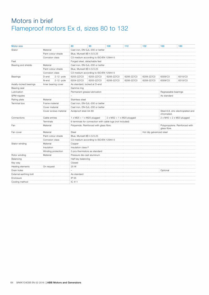
Motor size 80 90 100 112 132 160 180
Stator Material Cast iron, EN-GJL-200 or better
Paint colour shade Blue, Munsell 8B 4.5/3.25
Corrosion class C3 medium according to ISO/EN 12944-5
Feet Forged steel, detachable feet
Bearing end shields Material Cast iron, EN-GJL-200 or better
Paint colour shade Blue, Munsell 8B 4.5/3.25
Corrosion class C3 medium according to ISO/EN 12944-5
Bearings D-end 2-12 -pole 6205-2Z/C3 6205-2Z/C3 6206-2Z/C3 6206-2Z/C3 6208-2Z/C3 6309/C3 6310/C3
N-end 2-12 -pole 6204-2Z/C3 6205-2Z/C3 6206-2Z/C3 6206-2Z/C3 6208-2Z/C3 6309/C3 6310/C3
Axially-locked bearings Inner bearing cover As standard, locked at D-end
Bearing seal Gamma ring
Lubrication Permanent grease lubrication Regreasable bearings
SPM-nipples – As standard
Rating plate Material Stainless steel
Terminal box Frame material Cast iron, EN-GJL-200 or better
Cover material Cast iron, EN-GJL-200 or better
Cover screws material Acidproof steel A4-80 Steel 8.8, zinc electroplated and chromated.
Connections Cable entries 1 x M25 + 1 x M20 plugged 2 x M32 + 1 x M20 plugged 2 x M40 + 2 x M20 plugged
Terminals 6 terminals for connection with cable lugs (not included)
Fan Material Polyamide. Reinforced with glass fibre. Polypropylene. Reinforced with glass fibre.
Fan cover Material Steel Hot dip galvanized steel
Paint colour shade Blue, Munsell 8B 4.5/3.25
Corrosion class C3 medium according to ISO/EN 12944-5
Stator winding Material Copper
Insulation Insulation class F
Winding protection 3 pcs thermistors as standard
Rotor winding Material Pressure die-cast aluminum
Balancing Half key balancing
Key way Closed
Heating elements On request 25 W
Drain holes – Optional
External earthing bolt As standard
Enclosure IP 55
Cooling method IC 411
Motors in briefFlameproof motors Ex d, sizes 80 to 132
64 9AKK104006 EN 02-2016 | ABB Motors and Generators

Motors in briefFlameproof motors Ex d, sizes 200 to 450
Motor size 200 225 250 280 315 355 400 450
Stator Material Cast iron, EN-GJL-200 or better
Paint colour shade Blue, Munsell 8B 4.5/3.25
Corrosion class C3 medium according to ISO/EN 12944-5
Feet Cast iron, EN-GJL-200 or better, integrated with stator
Bearing end shields Material Cast iron, EN-GJL-200 or better
Paint colour shade Blue, Munsell 8B 4.5/3.25
Corrosion class C3 medium according to ISO/EN 12944-5
Bearings D-end 2-pole 6312M/C3 6313M/C3 6315M/C3 6316/C3 6316/C3 6316M/C3 6317M/C3 -
4-12 -pole 6312/C3 6313/C3 6315/C3 6316/C3 6319/C3 6322/C3 6324/C3 6326M/C3
N-end 2-pole 6310M/C3 6312M/C3 6313M/C3 6316/C3 6316/C3 6316M/C3 6317M/C3 -
4-12 -pole 6310/C3 6312/C3 6313/C3 6316/C3 6316/C3 6316/C3 6319/C3 6322M/C3
Axially-locked bearings Inner bearing cover As standard, locked at D-end
Bearing seal Gamma-ring Labyrinth seal
Lubrication Regreasable bearings
SPM-nipples As standard
Rating plate Material Stainless steel
Terminal box Frame material Cast iron, EN-GJL-200 or better
Cover material Cast iron, EN-GJL-200 or better
Cover screws material Steel 8.8, zinc electroplated and chromated
Connections Cable entries 2 x M50 + 2 x M20 plugged 2 x M63 + 2 x M20 plugged
2 x M75 + 2 x M20 plugged
Terminals 6 terminals for connection with cable lugs (not included)
Fan Material Polypropylene. Reinforced with glass fibre. Polypropylene reinforced with glass fibre or aluminum.
Fan cover Material Hot dip galvanized steel
Paint colour shade Blue, Munsell 8B 4.5/3.25
Corrosion class C3 medium according to ISO/EN 12944-5
Stator winding Material Copper
Insulation Insulation class F
Winding protection 3 pcs thermistors as standard
Rotor winding Material Pressure die-cast aluminum
Balancing Half key balancing
Key way Closed Open
Heating elements On request 25 W 60 W 120 W 200 W
Drain holes Optional
External earthing bolt As standard
Enclosure IP 55
Cooling method IC 411
ABB Motors and Generators | 9AKK104006 EN 02-2016 65
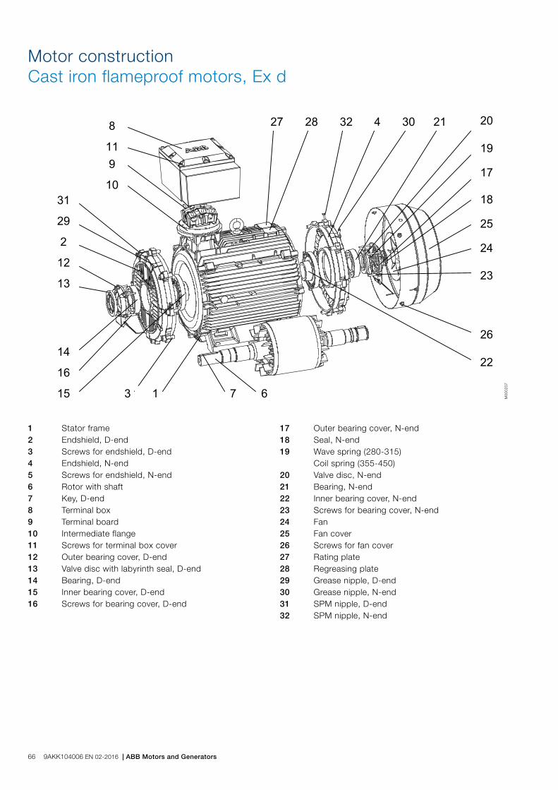
Motor constructionCast iron flameproof motors, Ex d
1 Stator frame 2 Endshield, D-end 3 Screws for endshield, D-end 4 Endshield, N-end 5 Screws for endshield, N-end 6 Rotor with shaft 7 Key, D-end 8 Terminal box 9 Terminal board 10 Intermediate flange 11 Screws for terminal box cover 12 Outer bearing cover, D-end 13 Valve disc with labyrinth seal, D-end 14 Bearing, D-end 15 Inner bearing cover, D-end 16 Screws for bearing cover, D-end
17 Outer bearing cover, N-end 18 Seal, N-end 19 Wave spring (280-315) Coil spring (355-450) 20 Valve disc, N-end 21 Bearing, N-end 22 Inner bearing cover, N-end 23 Screws for bearing cover, N-end 24 Fan 25 Fan cover 26 Screws for fan cover 27 Rating plate 28 Regreasing plate 29 Grease nipple, D-end 30 Grease nipple, N-end 31 SPM nipple, D-end 32 SPM nipple, N-end
M00
0207
66 9AKK104006 EN 02-2016 | ABB Motors and Generators

Flameproof motors, Ex de IIB/IIC T4 GbTotally enclosed squirrel cage three phase low voltage motors, Sizes 80 to 450, 0.55 to 950 kW
Ordering information 68
Rating plates 69
Technical data IE2 70
3000 r/min motors 70
1500 r/min motors 71
1000 r/min motors 72
750 r/min motors 73
Technical data IE3 74
3000 and 1500 r/min motors 74
1000 and 750 r/min motors 75
Variant codes 76
Mechanical design 81
Motor frame and drain holes 81
Heating elements 82
Bearings 83
Terminal box 90
Dimension drawings 98
Certificate examples 99
Flameproof motors Ex de in brief 100
Motor construction 102
ABB Motors and Generators | 9AKK104006 EN 02-2016 67

When placing an order, specify motor type, size and product code according to the following example.
Positions 1 - 4
3GKP: Totally enclosed frameproof motor Ex d with cast iron frame
Positions 5 and 6
IEC size
08: 80
09: 90
10: 100
11: 112
13: 132
16: 160
18: 180
20: 200
22: 225
25: 250
28: 280
31: 315
35: 355
40: 400
45: 450
Position 7
Speed (Pole pairs)
1: 2 poles
2: 4 poles
3: 6 poles
4: 8 poles
5: 10 poles
6: 12 poles
7: ≥ 12 poles
8: Two-speed motors
9: Multi-speed motors
Positions 8 to 10
Serial number
Position 11
- (Dash)
Position 12
Mounting arrangement
A: Foot-mounted, top-mounted terminal box
R: Foot-mounted, terminal box RHS seen from D-end
L: Foot-mounted, terminal box LHS seen from D-end
Ordering information
B: Flange-mounted, large flange with clearance holes
C: Flange-mounted, small flange with tapped holes
V: Flange-mounted, special flange
H: Foot/flange-mounted, large flange with clearance holes
J: Foot/flange-mounted, small flange with tapped holes
S: Foot/flange-mounted, terminal box RHS seen from D-end
T: Foot/flange-mounted, terminal box LHS seen from D-end
F: Foot/flange-mounted, special flange
Position 13
Voltage and frequency
Single-speed motors
B: 380 VΔ 50 Hz
D: 400 VΔ, 415 VΔ, 690 VY 50 Hz
E: 500 VΔ 50 Hz
F: 500 VY 50 Hz
S: 230 VΔ, 400 VY, 415 VY 50 Hz
T: 660 VΔ 50 Hz
U: 690 VΔ 50 Hz
X: Other rated voltage, connection or frequency, 690 V maximum
Position 14
Generation code G/H
Generation code is followed by variant codes according to the hazardous area, seen below and on corresponding pages with variant codes:
461 Ex d(e) design, Group IIC
Explanation of the product codeMotor type Motor size Product code Mounting arrangement code,
Voltage and frequency code,Generation code
Variant codes
M3KP 160MLA 3GKP 161 410 - ADH 002, etc. 1 2 3 4 5 6 7 8 9 10 11 12 13 14
Example
Motor type M3KP 160 MLA
Pole number 2
Mounting arrangement (IM-code) IM B3 (IM 1001)
Rated output 11 kW
Product code 3GKP161410-ADH
Variant codes if needed
68 9AKK104006 EN 02-2016 | ABB Motors and Generators

Rating plates
The rating plates are in table form giving values for speed, current and power factor for three voltages: 400V-415V-690V as standard. Other voltage and frequency combinations are possible and can be ordered with variant codes 002 or 209. Please see Variant code section.
The following information will be shown on the motor rating plate:
− Lowest nominal efficiency at 100 %, 75 % and 50 % rated load
− Efficiency level − Year of manufacture − Type of protection − Apparatus group − Temperature class − Identification number of the certification body − Certificate number (both ATEX and IECEx are stamped
on the rating plate as standard)
M00
0732
Motor sizes 80 to 450
Plates
ABB Motors and Generators | 9AKK104006 EN 02-2016 69
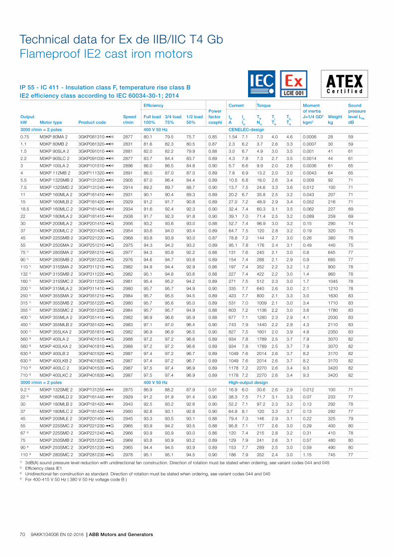
IP 55 - IC 411 - Insulation class F, temperature rise class BIE2 efficiency class according to IEC 60034-30-1; 2014
Technical data for Ex de IIB/IIC T4 Gb Flameproof IE2 cast iron motors
Output kW Motor type Product code
Speed r/min
EfficiencyPower factor cosphi
Current Torque Moment of inertia J=1/4 GD2 kgm2
Weight kg
Sound pressure level LPA dB
Full load 100%
3/4 load 75%
1/2 load 50%
IN A
Is IN
TN Nm
Tl TN
Tb TN
3000 r/min = 2 poles 400 V 50 Hz CENELEC-design
0.75 M3KP 80MA 2 3GKP081310-••H 2877 80.1 79.5 75.7 0.85 1.54 7.1 7.3 4.0 4.6 0.0006 28 59
1.1 M3KP 80MB 2 3GKP081320-••H 2831 81.6 82.3 80.5 0.87 2.3 6.2 3.7 2.6 3.3 0.0007 30 59
1.5 M3KP 90SLA 2 3GKP091010-••H 2881 82.0 82.2 79.9 0.88 3.0 6.7 4.9 3.0 3.5 0.001 41 61
2.2 M3KP 90SLC 2 3GKP091030-••H 2877 83.7 84.4 83.7 0.89 4.3 7.8 7.3 2.7 3.5 0.0014 44 61
3 M3KP 100LA 2 3GKP101510-••H 2896 86.0 86.5 84.8 0.90 5.7 6.6 9.9 2.0 2.6 0.0036 61 65
4 M3KP 112MB 2 3GKP111320-••H 2891 86.0 87.0 87.0 0.89 7.6 6.9 13.2 2.0 3.0 0.0043 64 65
5.5 M3KP 132SMB 2 3GKP131220-••H 2905 87.0 86.4 84.4 0.89 10.5 6.8 18.0 2.6 3.4 0.009 92 71
7.5 M3KP 132SMD 2 3GKP131240-••H 2914 89.2 89.7 88.7 0.90 13.7 7.5 24.6 3.3 3.6 0.012 100 71
11 M3KP 160MLA 2 3GKP161410-••H 2931 90.1 90.4 89.3 0.89 20.2 6.7 35.8 2.5 3.2 0.043 207 71
15 M3KP 160MLB 2 3GKP161420-••H 2929 91.2 91.7 90.8 0.89 27.0 7.2 48.9 2.9 3.4 0.052 216 71
18.5 M3KP 160MLC 2 3GKP161430-••H 2934 91.6 92.4 92.3 0.90 32.4 7.4 60.3 3.1 3.5 0.062 227 69
22 M3KP 180MLA 2 3GKP181410-••H 2938 91.7 92.3 91.8 0.90 39.1 7.0 71.4 2.5 3.2 0.089 259 69
30 M3KP 200MLA 2 3GKP201410-••G 2956 93.2 93.6 93.0 0.88 52.7 7.4 96.9 3.0 3.2 0.15 290 74
37 M3KP 200MLC 2 3GKP201430-••G 2954 93.6 94.0 93.4 0.89 64.7 7.5 120 2.8 3.2 0.19 320 75
45 M3KP 225SMB 2 3GKP221220-••G 2968 93.8 93.9 93.0 0.87 78.8 7.2 144 2.7 3.0 0.26 380 76
55 M3KP 250SMA 2 3GKP251210-••G 2975 94.3 94.2 93.2 0.89 95.1 7.8 176 2.4 3.1 0.49 440 75
75 1) M3KP 280SMA 2 3GKP281210-••G 2977 94.3 93.8 92.2 0.88 131 7.6 240 2.1 3.0 0.8 645 77
90 1) M3KP 280SMB 2 3GKP281220-••G 2976 94.6 94.7 93.8 0.89 154 7.4 288 2.1 2.9 0.9 685 77
110 1) M3KP 315SMA 2 3GKP311210-••G 2982 94.9 94.4 92.9 0.86 197 7.4 352 2.2 3.2 1.2 900 78
132 1) M3KP 315SMB 2 3GKP311220-••G 2982 95.1 94.8 93.6 0.88 227 7.4 422 2.2 3.0 1.4 960 78
160 1) M3KP 315SMC 2 3GKP311230-••G 2981 95.4 95.2 94.2 0.89 271 7.5 512 2.3 3.0 1.7 1045 78
200 1) M3KP 315MLA 2 3GKP311410-••G 2980 95.7 95.7 94.9 0.90 335 7.7 640 2.6 3.0 2.1 1210 78
250 1) M3KP 355SMA 2 3GKP351210-••G 2984 95.7 95.5 94.5 0.89 423 7.7 800 2.1 3.3 3.0 1630 83
315 1) M3KP 355SMB 2 3GKP351220-••G 2980 95.7 95.6 95.0 0.89 531 7.0 1009 2.1 3.0 3.4 1710 83
355 1) M3KP 355SMC 2 3GKP351230-••G 2984 95.7 95.7 94.9 0.88 603 7.2 1136 2.2 3.0 3.6 1780 83
400 1) M3KP 355MLA 2 3GKP351410-••G 2982 96.9 96.6 95.9 0.88 677 7.1 1280 2.3 2.9 4.1 2030 83
450 1) M3KP 355MLB 2 3GKP351420-••G 2983 97.1 97.0 96.4 0.90 743 7.9 1440 2.2 2.9 4.3 2110 83
500 1) M3KP 355LKA 2 3GKP351810-••G 2982 96.9 96.9 96.5 0.90 827 7.5 1601 2.0 3.9 4.8 2350 83
560 3) M3KP 400LA 2 3GKP401510-••G 2988 97.2 97.2 96.6 0.89 934 7.8 1789 2.5 3.7 7.9 3070 82
560 3) M3KP 400LKA 2 3GKP401810-••G 2988 97.2 97.2 96.6 0.89 934 7.8 1789 2.5 3.7 7.9 3070 82
630 3) M3KP 400LB 2 3GKP401520-••G 2987 97.4 97.2 96.7 0.89 1049 7.6 2014 2.6 3.7 8.2 3170 82
630 3) M3KP 400LKB 2 3GKP401820-••G 2987 97.4 97.2 96.7 0.89 1049 7.6 2014 2.6 3.7 8.2 3170 82
710 3) M3KP 400LC 2 3GKP401530-••G 2987 97.5 97.4 96.9 0.89 1178 7.2 2270 2.6 3.4 9.3 3420 82
710 3) M3KP 400LKC 2 3GKP401830-••G 2987 97.5 97.4 96.9 0.89 1178 7.2 2270 2.6 3.4 9.3 3420 82
3000 r/min = 2 poles 400 V 50 Hz High-output design
9.2 2) M3KP 132SME 2 3GKP131250-••H 2875 86.9 88.2 87.9 0.91 16.9 6.0 30.6 2.6 2.9 0.012 100 71
22 2) M3KP 160MLD 2 3GKP161440-••H 2929 91.2 91.9 91.4 0.90 38.3 7.5 71.7 3.1 3.3 0.07 233 77
30 M3KP 180MLB 2 3GKP181420-••H 2943 92.5 93.2 92.6 0.90 52.2 7.1 97.2 2.3 3.2 0.13 292 78
37 M3KP 180MLC 2 3GKP181430-••H 2950 92.8 93.1 92.8 0.90 64.9 8.1 120 3.3 3.7 0.13 292 77
45 M3KP 200MLE 2 3GKP201450-••G 2945 93.3 93.5 93.1 0.88 79.4 7.3 146 2.9 3.1 0.22 325 79
55 M3KP 225SMC 2 3GKP221230-••G 2965 93.9 94.2 93.5 0.88 95.8 7.1 177 2.6 3.0 0.29 400 80
67 4) M3KP 225SMD 2 3GKP221240-••G 2966 93.9 93.9 93.0 0.86 120 7.4 215 2.8 3.2 0.31 410 78
75 M3KP 250SMB 2 3GKP251220-••G 2969 93.8 93.9 93.2 0.89 129 7.9 241 2.6 3.1 0.57 480 80
90 4) M3KP 250SMC 2 3GKP251230-••G 2965 94.4 94.5 93.9 0.89 153 7.7 289 2.5 3.0 0.59 490 80
110 3) M3KP 280SMC 2 3GKP281230-••G 2978 95.1 95.1 94.5 0.90 186 7.9 352 2.4 3.0 1.15 745 77
1) 3dB(A) sound pressure level reduction with unidirectional fan construction. Direction of rotation must be stated when ordering, see variant codes 044 and 0452) Efficiency class IE13) Unidirectional fan construction as standard. Direction of rotation must be stated when ordering, see variant codes 044 and 0454) For 400-415 V 50 Hz ( 380 V 50 Hz voltage code B )
70 9AKK104006 EN 02-2016 | ABB Motors and Generators

IP 55 - IC 411 - Insulation class F, temperature rise class BIE2 efficiency class according to IEC 60034-30-1; 2014
Technical data for Ex de IIB/IIC T4 Gb Flameproof IE2 cast iron motors
1) Temperature rise class F2) Efficiency class IE13) For 400-415 V 50 Hz ( 380 V 50 Hz voltage code B)
Output kW Motor type Product code
Speed r/min
EfficiencyPower factor cosphi
Current Torque Moment of inertia J=1/4 GD2 kgm2
Weight kg
Sound pressure level LPA dB
Full load 100%
3/4 load 75%
1/2 load 50%
IN A
Is IN
TN Nm
Tl TN
Tb TN
1500 r/min = 4 poles 400 V 50 Hz CENELEC-design
0.55 2) M3KP 80MA 4 3GKP082310-••H 1421 76.6 76.9 74.1 0.73 1.49 4.7 3.7 2.2 2.7 0.001 29 59
0.75 M3KP 80MB 4 3GKP082320-••H 1416 80.2 80.1 77.5 0.75 1.87 5.4 5.0 2.7 3.1 0.0012 31 59
1.1 M3KP 90SLA 4 3GKP092010-••H 1432 82.2 82.1 79.6 0.77 2.5 6.5 7.3 3.0 3.5 0.002 42 54
1.5 M3KP 90SLC 4 3GKP092030-••H 1431 83.2 83.6 81.9 0.78 3.3 6.6 10.0 3.3 3.7 0.003 44 54
2.2 M3KP 100LA 4 3GKP102510-••H 1437 85.5 86.5 85.8 0.84 4.4 5.9 14.6 2.3 3.0 0.0075 61 52
3 M3KP 100LB 4 3GKP102520-••H 1444 86.5 87.5 86.8 0.83 6.1 6.4 19.9 2.7 3.4 0.0081 63 59
4 M3KP 112MC 4 3GKP112330-••H 1458 88.2 87.7 85.4 0.78 8.6 9.2 26.3 3.4 4.9 0.013 72 61
5.5 M3KP 132SMB 4 3GKP132220-••H 1458 89.5 89.2 87.3 0.80 11.7 7.9 36.0 3.7 3.8 0.023 102 60
7.5 M3KP 132SMD 4 3GKP132240-••H 1460 89.2 89.0 87.3 0.76 16.7 8.4 49.2 4.0 3.9 0.034 105 60
11 M3KP 160MLC 4 3GKP162430-••H 1470 91.2 91.3 90.0 0.82 21.5 8.0 71.5 3.3 3.8 0.096 226 62
15 M3KP 160MLE 4 3GKP162450-••H 1467 92.0 92.3 91.8 0.84 28.5 8.0 97.7 3.3 3.2 0.13 249 61
18.5 M3KP 180MLA 4 3GKP182410-••H 1474 91.6 92.1 91.5 0.83 35.7 7.2 120 2.6 3.1 0.19 271 62
22 M3KP 180MLB 4 3GKP182420-••H 1474 92.2 92.5 91.9 0.82 42.0 7.7 142 2.8 3.4 0.23 290 62
30 M3KP 200MLB 4 3GKP202420-••G 1471 92.5 93.2 93.1 0.84 55.0 7.4 194 3.0 2.8 0.34 320 61
37 M3KP 225SMB 4 3GKP222220-••G 1480 93.6 93.9 93.4 0.85 69.0 7.6 239 3.2 2.9 0.42 370 67
45 M3KP 225SMC 4 3GKP222230-••G 1477 94.1 94.4 94.3 0.86 78.4 7.6 291 3.2 2.7 0.49 405 67
55 M3KP 250SMA 4 3GKP252210-••G 1479 94.7 94.7 94.1 0.84 100 7.2 355 2.5 3.1 0.72 430 66
75 M3KP 280SMA 4 3GKP282210-••G 1484 94.5 94.7 94.4 0.85 134 6.9 482 2.5 2.8 1.25 645 68
90 M3KP 280SMB 4 3GKP282220-••G 1483 94.7 95.0 94.5 0.85 160 7.2 579 2.5 2.7 1.5 685 68
110 M3KP 315SMA 4 3GKP312210-••G 1487 95.1 95.1 94.3 0.86 194 7.2 706 2.3 2.8 2.3 920 70
132 M3KP 315SMB 4 3GKP312220-••G 1487 95.4 95.4 94.7 0.86 232 7.1 847 2.3 2.7 2.6 980 70
160 M3KP 315SMC 4 3GKP312230-••G 1487 95.3 95.3 94.8 0.85 284 7.2 1027 2.4 2.9 2.9 1020 70
200 M3KP 315MLA 4 3GKP312410-••G 1486 95.6 95.6 95.3 0.86 351 7.2 1285 2.5 2.9 3.5 1180 70
250 M3KP 355SMA 4 3GKP352210-••G 1488 95.9 96.0 95.5 0.85 442 7.1 1604 2.3 2.7 5.9 1640 74
315 M3KP 355SMB 4 3GKP352220-••G 1488 95.9 96.2 95.8 0.86 550 7.3 2021 2.3 2.8 6.9 1810 74
355 M3KP 355SMC 4 3GKP352230-••G 1487 95.9 96.2 95.9 0.87 614 6.8 2279 2.4 2.7 7.2 1850 78
400 M3KP 355MLA 4 3GKP352410-••G 1489 96.3 96.3 95.9 0.85 705 6.8 2565 2.3 2.6 8.4 2170 78
450 M3KP 355MLB 4 3GKP352420-••G 1490 96.7 96.7 96.1 0.86 780 6.9 2884 2.3 2.9 8.4 2170 78
500 M3KP 355LKA 4 3GKP352810-••G 1490 97.0 97.0 96.5 0.86 865 6.8 3204 2.0 3.0 10 2530 78
560 M3KP 400LA 4 3GKP402510-••G 1491 96.8 96.8 96.3 0.85 982 7.4 3586 2.4 2.8 15 3040 78
630 M3KP 400LB 4 3GKP402520-••G 1491 97.0 97.0 96.5 0.87 1077 7.6 4034 2.2 2.9 16 3420 78
710 1) M3KP 400LC 4 3GKP402530-••G 1491 97.1 97.1 96.7 0.86 1227 7.6 4547 2.4 3.0 17 3520 78
560 M3KP 400LKA 4 3GKP402810-••G 1491 96.8 96.8 96.3 0.85 982 7.4 3586 2.4 2.8 15 3040 78
630 M3KP 400LKB 4 3GKP402820-••G 1491 97.0 97.0 96.5 0.87 1077 7.6 4034 2.2 2.9 16 3420 78
710 1) M3KP 400LKC 4 3GKP402830-••G 1491 97.1 97.1 96.7 0.86 1227 7.6 4547 2.4 3.0 17 3520 78
780 M3KP 450LA 4 3GKP452510-••G 1491 96.7 96.6 96.0 0.85 1369 7.1 4995 1.4 3.0 23 4050 85
870 M3KP 450LB 4 3GKP452520-••G 1492 96.8 96.7 96.2 0.85 1526 7.2 5568 1.4 3.0 25 4350 85
950 M3KP 450LC 4 3GKP452530-••G 1491 96.9 96.9 96.5 0.85 1664 7.3 6084 1.4 3.0 30 4700 85
1500 r/min = 4 poles 400 V 50 Hz High-output design
18.5 M3KP 160MLF 4 3GKP162460-••H 1469 91.8 92.2 91.6 0.83 35 8.2 120.3 3.5 3.8 0.13 249 68
22 2) M3KP 160MLG 4 3GKP162470-••H 1466 90.8 91.1 90.3 0.81 43.9 8.3 143.3 2.9 3.9 0.13 249 68
30 2) M3KP 180MLC 4 3GKP182430-••H 1466 92.1 92.4 91.8 0.81 59.6 7.6 194.5 2.2 3.3 0.248 298 66
37 M3KP 200MLC 4 3GKP202430-••G 1475 93.0 93.1 92.4 0.82 70.5 7.5 239 3.5 3.2 0.34 320 73
55 M3KP 225SMD 4 3GKP222240-••G 1483 94.3 94.4 93.9 0.83 101 7.4 354 3.4 2.9 0.55 425 68
60 3) M3KP 225SME 4 3GKP222250-••G 1477 93.6 93.7 92.9 0.84 110 8.0 387 3.6 3.0 0.55 425 74
62 2), 3) M3KP 225SME 4 3GKP222250-••G 1480 93.5 93.6 92.8 0.84 114 7.7 400 3.5 2.9 0.55 425 74
75 2) M3KP 250SMB 4 3GKP252220-••G 1476 93.8 94.2 93.9 0.86 135 7.0 485 2.6 2.9 0.88 485 73
86 M3KP 250SMC 4 3GKP252230-••G 1477 94.9 95.3 95.0 0.85 155 7.8 556 2.9 3.5 0.98 510 74
110 M3KP 280SMC 4 3GKP282230-••G 1485 95.1 95.4 95.1 0.86 193 7.6 707 3.0 3.0 1.85 745 68
ABB Motors and Generators | 9AKK104006 EN 02-2016 71
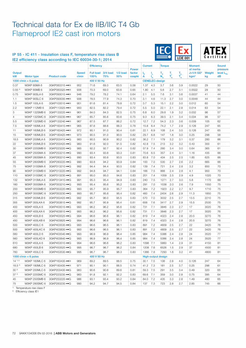
IP 55 - IC 411 - Insulation class F, temperature rise class BIE2 efficiency class according to IEC 60034-30-1; 2014
Technical data for Ex de IIB/IIC T4 Gb Flameproof IE2 cast iron motors
1) Temperature rise class F2) Efficiency class IE1
Output kW Motor type Product code
Speed r/min
EfficiencyPower factor cosphi
Current Torque Moment of inertia J=1/4 GD2 kgm2
Weight kg
Sound pressure level LPA dB
Full load 100%
3/4 load 75%
1/2 load 50%
IN A
Is IN
TN Nm
Tl TN
Tb TN
1000 r/min = 6 poles 400 V 50 Hz CENELEC-design
0.37 M3KP 80MA 6 3GKP083310-••H 952 71.6 69.3 63.5 0.58 1.37 4.3 3.7 3.6 3.9 0.0022 29 50
0.55 2) M3KP 80MB 6 3GKP083320-••H 938 70.3 69.0 63.6 0.65 1.80 4.1 5.6 2.7 3.1 0.0022 29 50
0.75 M3KP 90SLA 6 3GKP093010-••H 946 79.2 78.2 74.1 0.64 2.1 5.5 7.6 3.1 3.6 0.0037 41 44
1.1 M3KP 90SLC 6 3GKP093030-••H 938 78.5 77.9 74.3 0.70 3.1 4.6 11.3 2.7 3.0 0.0048 44 44
1.5 M3KP 100LA 6 3GKP103510-••H 951 81.6 81.4 78.8 0.72 3.7 5.3 15.1 2.2 3.0 0.012 60 54
2.2 M3KP 112MB 6 3GKP113320-••H 950 82.5 82.2 79.4 0.72 5.5 5.0 22.1 2.1 2.8 0.014 63 54
3 M3KP 132SMB 6 3GKP133220-••H 961 84.0 84.3 82.5 0.75 6.8 6.0 29.8 1.9 3.2 0.032 96 57
4 M3KP 132SMC 6 3GKP133230-••H 967 85.7 85.6 83.6 0.75 9.3 6.3 39.5 2.1 3.4 0.034 98 57
5.5 M3KP 132SMD 6 3GKP133240-••H 967 87.5 87.7 86.2 0.72 12.7 7.2 54.3 2.3 3.6 0.039 105 62
7.5 M3KP 160MLA 6 3GKP163410-••H 965 87.6 88.6 88.3 0.78 15.8 6.4 74.2 1.7 2.9 0.126 247 65
11 M3KP 160MLB 6 3GKP163420-••H 972 90.1 91.0 90.4 0.81 22.1 6.9 108 2.4 3.5 0.126 247 65
15 M3KP 180MLB 6 3GKP183420-••H 973 90.5 91.0 90.5 0.82 29.7 6.8 147 1.8 3.0 0.25 298 58
18.5 M3KP 200MLA 6 3GKP203410-••G 983 90.5 90.9 90.2 0.82 36.2 7.1 179 3.2 3.1 0.37 280 66
22 M3KP 200MLB 6 3GKP203420-••G 983 91.6 92.0 91.5 0.82 42.8 7.5 213 3.2 3.2 0.43 300 61
30 M3KP 225SMB 6 3GKP223220-••G 985 92.2 92.7 92.4 0.82 57.9 7.4 290 3.4 3.0 0.64 365 61
37 M3KP 250SMA 6 3GKP253210-••G 990 93.4 93.8 93.3 0.81 70.6 6.5 357 2.4 3.1 1.16 435 66
45 M3KP 280SMA 6 3GKP283210-••G 990 93.4 93.8 93.5 0.83 83.8 7.0 434 2.5 2.5 1.85 625 66
55 M3KP 280SMB 6 3GKP283220-••G 990 93.8 94.2 93.9 0.84 100 7.0 530 2.7 2.6 2.2 665 66
75 M3KP 315SMA 6 3GKP313210-••G 992 94.4 94.4 93.5 0.82 139 7.4 721 2.4 2.8 3.2 850 70
90 M3KP 315SMB 6 3GKP313220-••G 992 94.8 94.7 94.1 0.84 166 7.5 866 2.4 2.8 4.1 950 70
110 M3KP 315SMC 6 3GKP313230-••G 991 95.0 95.0 94.6 0.83 201 7.4 1059 2.5 2.9 4.9 1020 70
132 M3KP 315MLA 6 3GKP313410-••G 991 95.3 95.4 94.9 0.83 240 7.5 1271 2.7 3.0 5.8 1170 68
160 M3KP 355SMA 6 3GKP353210-••G 993 95.4 95.6 95.2 0.83 291 7.0 1538 2.0 2.6 7.9 1550 75
200 M3KP 355SMB 6 3GKP353220-••G 993 95.7 95.9 95.7 0.83 364 7.2 1923 2.2 2.7 9.7 1710 75
250 M3KP 355SMC 6 3GKP353230-••G 993 95.7 95.8 95.4 0.82 460 7.4 2404 2.6 2.9 11.3 1850 75
315 M3KP 355MLB 6 3GKP353420-••G 992 95.7 96.0 95.5 0.83 570 7.0 3032 2.5 2.7 13.5 2210 75
355 M3KP 355LKA 6 3GKP353810-••G 992 95.7 95.9 95.4 0.81 658 7.6 3417 2.7 2.9 15.5 2530 75
400 M3KP 400LA 6 3GKP403510-••G 993 96.2 96.2 95.6 0.82 731 7.1 3846 2.3 2.7 17 3020 76
400 M3KP 400LKA 6 3GKP403810-••G 993 96.2 96.2 95.6 0.82 731 7.1 3846 2.3 2.7 17 3020 76
450 M3KP 400LB 6 3GKP403520-••G 994 96.6 96.6 96.1 0.82 819 7.4 4323 2.4 2.8 20.5 3270 76
450 M3KP 400LKB 6 3GKP403820-••G 994 96.6 96.6 96.1 0.82 819 7.4 4323 2.4 2.8 20.5 3270 76
500 M3KP 400LC 6 3GKP403530-••G 993 96.6 96.5 96.1 0.83 891 7.2 4809 2.5 2.7 22 3420 76
500 M3KP 400LKC 6 3GKP403830-••G 993 96.6 96.5 96.1 0.83 891 7.2 4809 2.5 2.7 22 3420 76
560 M3KP 400LD 6 3GKP403540-••G 993 96.9 96.9 96.4 0.85 984 7.4 5386 2.4 2.8 24 3520 77
560 M3KP 400LKD 6 3GKP403840-••G 993 96.9 96.9 96.4 0.85 984 7.4 5386 2.4 2.8 24 3520 77
610 M3KP 450LA 6 3GKP453510-••G 994 96.6 96.6 96.2 0.83 1098 7.1 5860 1.4 2.9 31 4150 81
680 M3KP 450LB 6 3GKP453520-••G 995 96.7 96.7 96.2 0.84 1208 7.6 6526 1.5 2.9 37 4500 81
760 M3KP 450LC 6 3GKP453530-••G 995 96.7 96.7 96.3 0.83 1366 7.8 7293 1.6 3.2 41 4800 81
1000 r/min = 6 poles 400 V 50 Hz High-output design
14 1) 2) M3KP 160MLC 6 3GKP163430-••H 969 89.2 89.5 88.5 0.75 30.1 7.5 138 2.8 4.0 0.126 247 64
18.5 2) M3KP 180MLC 6 3GKP183430-••H 971 90.1 90.1 88.5 0.74 41.2 7.3 181 2.5 3.7 0.25 298 61
30 2) M3KP 200MLC 6 3GKP203430-••G 983 90.6 90.8 89.6 0.81 59.3 7.5 291 3.5 3.4 0.49 320 65
37 2) M3KP 225SMC 6 3GKP223230-••G 983 91.8 92.1 92.2 0.83 69.6 7.1 359 3.0 2.8 0.75 395 64
45 M3KP 250SMB 6 3GKP253220-••G 986 93.1 93.4 93.2 0.84 84.0 7.2 435 3.3 2.8 1.49 480 65
75 M3KP 280SMC 6 3GKP283230-••G 990 94.2 94.7 94.5 0.84 137 7.3 723 2.8 2.7 2.85 745 66
72 9AKK104006 EN 02-2016 | ABB Motors and Generators
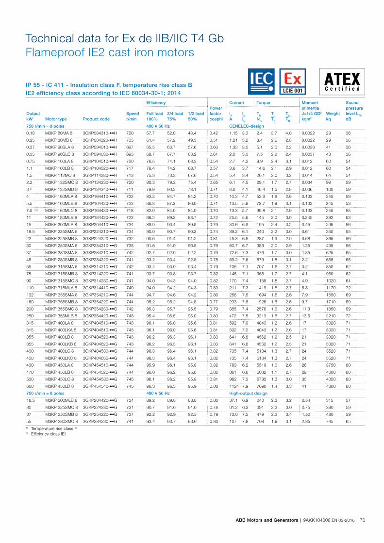
IP 55 - IC 411 - Insulation class F, temperature rise class BIE2 efficiency class according to IEC 60034-30-1; 2014
Technical data for Ex de IIB/IIC T4 Gb Flameproof IE2 cast iron motors
1) Temperature rise class F2) Efficiency class IE1
Output kW Motor type Product code
Speed r/min
EfficiencyPower factor cosphi
Current Torque Moment of inertia J=1/4 GD2 kgm2
Weight kg
Sound pressure level LPA dB
Full load 100%
3/4 load 75%
1/2 load 50%
IN A
Is IN
TN Nm
Tl TN
Tb TN
750 r/min = 8 poles 400 V 50 Hz CENELEC-design
0.18 M3KP 80MA 8 3GKP084310-••H 720 57.7 52.0 43.4 0.42 1.15 3.3 2.4 3.7 4.0 0.0022 29 36
0.25 M3KP 80MB 8 3GKP084320-••H 705 61.4 57.2 49.5 0.51 1.21 3.2 3.4 2.6 2.8 0.0022 29 36
0.37 M3KP 90SLA 8 3GKP094010-••H 697 65.5 63.7 57.6 0.63 1.33 3.0 5.1 2.0 2.2 0.0036 41 36
0.55 M3KP 90SLC 8 3GKP094030-••H 695 68.7 67.7 63.2 0.61 2.0 3.0 7.5 2.2 2.4 0.0037 43 36
0.75 M3KP 100LA 8 3GKP104510-••H 720 76.5 74.1 68.3 0.54 2.7 4.2 9.9 2.4 3.1 0.012 60 54
1.1 M3KP 100LB 8 3GKP104520-••H 717 76.4 74.2 68.7 0.57 3.6 3.7 14.6 2.1 2.9 0.012 60 54
1.5 M3KP 112MC 8 3GKP114330-••H 713 75.3 73.3 67.6 0.54 5.4 3.4 20.1 2.0 3.2 0.014 64 54
2.2 M3KP 132SMC 8 3GKP134230-••H 720 80.3 79.2 75.4 0.65 6.1 4.5 29.1 1.7 2.7 0.034 98 59
3 2) M3KP 132SMD 8 3GKP134240-••H 711 79.9 80.3 78.1 0.71 8.0 4.1 40.4 1.5 2.8 0.036 100 59
4 M3KP 160MLA 8 3GKP164410-••H 722 83.3 84.7 84.2 0.70 10.3 4.7 52.9 1.6 2.6 0.133 245 59
5.5 M3KP 160MLB 8 3GKP164420-••H 723 86.8 87.2 86.0 0.71 13.5 5.8 72.7 1.9 3.1 0.133 245 53
7.5 1) 2) M3KP 160MLC 8 3GKP164430-••H 718 82.0 84.0 84.0 0.70 19.3 5.7 99.8 2.1 2.9 0.133 245 55
11 M3KP 180MLB 8 3GKP184420-••H 723 88.3 89.2 88.7 0.72 25.5 5.6 145 2.0 3.0 0.245 292 63
15 M3KP 200MLA 8 3GKP204410-••G 734 89.9 90.4 89.5 0.79 30.6 6.9 195 2.4 3.2 0.45 295 56
18.5 M3KP 225SMA 8 3GKP224210-••G 734 90.0 90.7 90.2 0.74 39.2 6.1 240 2.2 3.0 0.61 350 55
22 M3KP 225SMB 8 3GKP224220-••G 732 90.6 91.4 91.2 0.81 45.3 6.5 287 1.9 2.9 0.68 365 56
30 M3KP 250SMA 8 3GKP254210-••G 735 91.6 91.0 90.5 0.79 60.7 6.7 389 2.0 2.9 1.25 435 56
37 M3KP 280SMA 8 3GKP284210-••G 742 92.7 92.9 92.2 0.79 72.6 7.3 476 1.7 3.0 1.85 625 65
45 M3KP 280SMB 8 3GKP284220-••G 741 93.2 93.4 92.8 0.78 89.2 7.6 579 1.8 3.1 2.2 665 65
55 M3KP 315SMA 8 3GKP314210-••G 742 93.4 93.9 93.4 0.79 106 7.1 707 1.6 2.7 3.2 850 62
75 M3KP 315SMB 8 3GKP314220-••G 741 93.7 93.8 93.7 0.82 146 7.1 966 1.7 2.7 4.1 950 62
90 M3KP 315SMC 8 3GKP314230-••G 741 94.0 94.3 94.0 0.82 170 7.4 1159 1.8 2.7 4.9 1020 64
110 M3KP 315MLA 8 3GKP314410-••G 740 94.0 94.2 94.3 0.83 211 7.3 1419 1.8 2.7 5.8 1170 72
132 M3KP 355SMA 8 3GKP354210-••G 744 94.7 94.6 94.2 0.80 256 7.5 1694 1.5 2.6 7.9 1550 69
160 M3KP 355SMB 8 3GKP354220-••G 744 95.2 95.2 94.8 0.77 293 7.6 1926 1.6 2.6 9.7 1710 69
200 M3KP 355SMC 8 3GKP354230-••G 742 95.3 95.7 95.5 0.79 385 7.4 2576 1.6 2.6 11.3 1850 69
250 M3KP 355MLB 8 3GKP354420-••G 743 95.4 95.5 95.0 0.80 472 7.5 3213 1.6 2.7 13.5 2210 72
315 M3KP 400LA 8 3GKP404510-••G 743 96.1 96.0 95.6 0.81 592 7.0 4043 1.2 2.6 17 3020 71
315 M3KP 400LKA 8 3GKP404810-••G 743 96.1 96.0 95.6 0.81 592 7.0 4043 1.2 2.6 17 3020 71
355 M3KP 400LB 8 3GKP404520-••G 743 96.2 96.3 96.1 0.83 641 6.8 4562 1.2 2.5 21 3320 71
355 M3KP 400LKB 8 3GKP404820-••G 743 96.2 96.3 96.1 0.83 641 6.8 4562 1.2 2.5 21 3320 71
400 M3KP 400LC 8 3GKP404530-••G 744 96.3 96.4 96.1 0.82 735 7.4 5134 1.3 2.7 24 3520 71
400 M3KP 400LKC 8 3GKP404830-••G 744 96.3 96.4 96.1 0.82 735 7.4 5134 1.3 2.7 24 3520 71
430 M3KP 450LA 8 3GKP454510-••G 744 95.9 96.1 95.8 0.82 789 6.2 5519 1.0 2.6 26 3750 80
470 M3KP 450LB 8 3GKP454520-••G 744 96.0 96.2 95.8 0.82 861 6.6 6032 1.1 2.7 29 4000 80
530 M3KP 450LC 8 3GKP454530-••G 745 96.1 96.2 95.8 0.81 982 7.3 6793 1.3 3.0 35 4350 80
600 M3KP 450LD 8 3GKP454540-••G 745 96.3 96.3 95.9 0.80 1124 7.9 7690 1.4 3.3 41 4800 80
750 r/min = 8 poles 400 V 50 Hz High-output design
18.5 M3KP 200MLB 8 3GKP204420-••G 734 89.2 89.8 88.8 0.80 37.1 6.9 240 2.2 3.2 0.54 315 57
30 M3KP 225SMC 8 3GKP224230-••G 731 90.7 91.6 91.6 0.78 61.2 6.3 391 2.3 3.0 0.75 390 59
37 M3KP 250SMB 8 3GKP254220-••G 737 92.2 92.9 92.5 0.79 73.0 7.5 479 2.3 3.4 1.52 480 59
55 M3KP 280SMC 8 3GKP284230-••G 741 93.4 93.7 93.6 0.80 107 7.9 708 1.9 3.1 2.85 745 65
ABB Motors and Generators | 9AKK104006 EN 02-2016 73
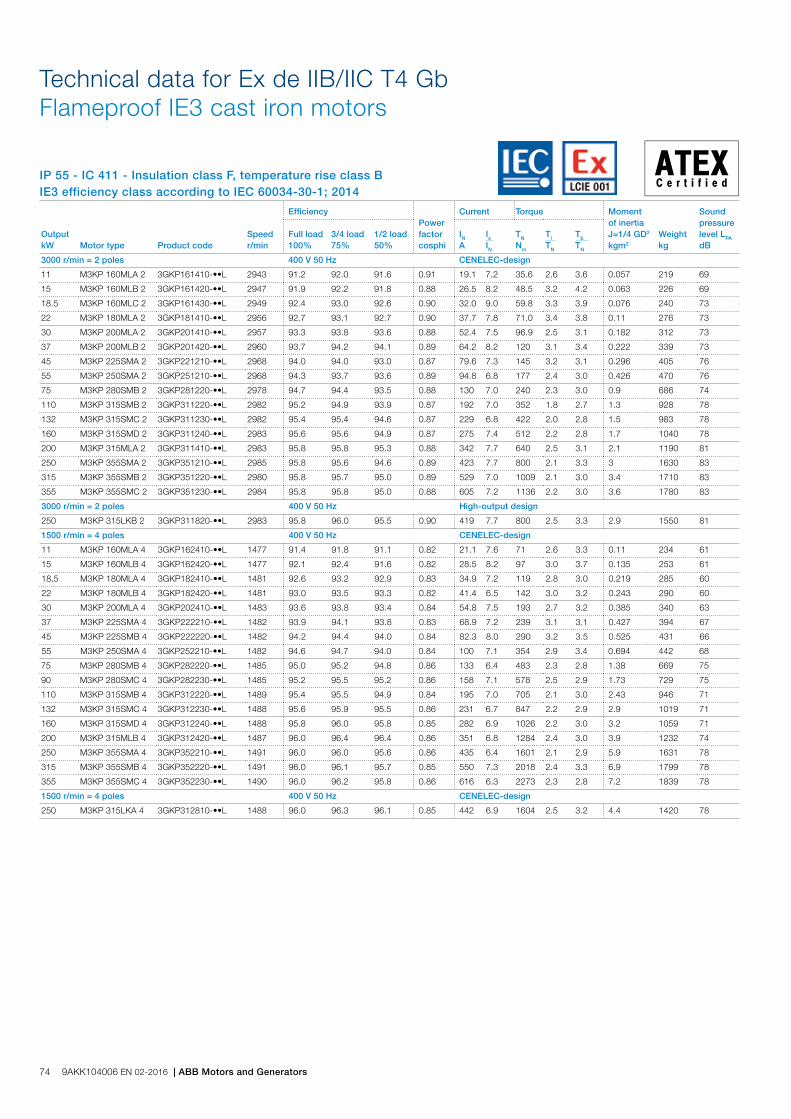
IP 55 - IC 411 - Insulation class F, temperature rise class BIE3 efficiency class according to IEC 60034-30-1; 2014
Technical data for Ex de IIB/IIC T4 Gb Flameproof IE3 cast iron motors
Output kW Motor type Product code
Speed r/min
EfficiencyPower factor cosphi
Current Torque Moment of inertia J=1/4 GD2 kgm2
Weight kg
Sound pressure level LPA dB
Full load 100%
3/4 load 75%
1/2 load 50%
IN A
Is IN
TN Nm
Tl TN
Tb TN
3000 r/min = 2 poles 400 V 50 Hz CENELEC-design
11 M3KP 160MLA 2 3GKP161410-••L 2943 91.2 92.0 91.6 0.91 19.1 7.2 35.6 2.6 3.6 0.057 219 69
15 M3KP 160MLB 2 3GKP161420-••L 2947 91.9 92.2 91.8 0.88 26.5 8.2 48.5 3.2 4.2 0.063 226 69
18.5 M3KP 160MLC 2 3GKP161430-••L 2949 92.4 93.0 92.6 0.90 32.0 9.0 59.8 3.3 3.9 0.076 240 73
22 M3KP 180MLA 2 3GKP181410-••L 2956 92.7 93.1 92.7 0.90 37.7 7.8 71.0 3.4 3.8 0.11 276 73
30 M3KP 200MLA 2 3GKP201410-••L 2957 93.3 93.8 93.6 0.88 52.4 7.5 96.9 2.5 3.1 0.182 312 73
37 M3KP 200MLB 2 3GKP201420-••L 2960 93.7 94.2 94.1 0.89 64.2 8.2 120 3.1 3.4 0.222 339 73
45 M3KP 225SMA 2 3GKP221210-••L 2968 94.0 94.0 93.0 0.87 79.6 7.3 145 3.2 3.1 0.296 405 76
55 M3KP 250SMA 2 3GKP251210-••L 2968 94.3 93.7 93.6 0.89 94.8 6.8 177 2.4 3.0 0.426 470 76
75 M3KP 280SMB 2 3GKP281220-••L 2978 94.7 94.4 93.5 0.88 130 7.0 240 2.3 3.0 0.9 686 74
110 M3KP 315SMB 2 3GKP311220-••L 2982 95.2 94.9 93.9 0.87 192 7.0 352 1.8 2.7 1.3 928 78
132 M3KP 315SMC 2 3GKP311230-••L 2982 95.4 95.4 94.6 0.87 229 6.8 422 2.0 2.8 1.5 983 78
160 M3KP 315SMD 2 3GKP311240-••L 2983 95.6 95.6 94.9 0.87 275 7.4 512 2.2 2.8 1.7 1040 78
200 M3KP 315MLA 2 3GKP311410-••L 2983 95.8 95.8 95.3 0.88 342 7.7 640 2.5 3.1 2.1 1190 81
250 M3KP 355SMA 2 3GKP351210-••L 2985 95.8 95.6 94.6 0.89 423 7.7 800 2.1 3.3 3 1630 83
315 M3KP 355SMB 2 3GKP351220-••L 2980 95.8 95.7 95.0 0.89 529 7.0 1009 2.1 3.0 3.4 1710 83
355 M3KP 355SMC 2 3GKP351230-••L 2984 95.8 95.8 95.0 0.88 605 7.2 1136 2.2 3.0 3.6 1780 83
3000 r/min = 2 poles 400 V 50 Hz High-output design
250 M3KP 315LKB 2 3GKP311820-••L 2983 95.8 96.0 95.5 0.90 419 7.7 800 2.5 3.3 2.9 1550 81
1500 r/min = 4 poles 400 V 50 Hz CENELEC-design
11 M3KP 160MLA 4 3GKP162410-••L 1477 91.4 91.8 91.1 0.82 21.1 7.6 71 2.6 3.3 0.11 234 61
15 M3KP 160MLB 4 3GKP162420-••L 1477 92.1 92.4 91.6 0.82 28.5 8.2 97 3.0 3.7 0.135 253 61
18.5 M3KP 180MLA 4 3GKP182410-••L 1481 92.6 93.2 92.9 0.83 34.9 7.2 119 2.8 3.0 0.219 285 60
22 M3KP 180MLB 4 3GKP182420-••L 1481 93.0 93.5 93.3 0.82 41.4 6.5 142 3.0 3.2 0.243 290 60
30 M3KP 200MLA 4 3GKP202410-••L 1483 93.6 93.8 93.4 0.84 54.8 7.5 193 2.7 3.2 0.385 340 63
37 M3KP 225SMA 4 3GKP222210-••L 1482 93.9 94.1 93.8 0.83 68.9 7.2 239 3.1 3.1 0.427 394 67
45 M3KP 225SMB 4 3GKP222220-••L 1482 94.2 94.4 94.0 0.84 82.3 8.0 290 3.2 3.5 0.525 431 66
55 M3KP 250SMA 4 3GKP252210-••L 1482 94.6 94.7 94.0 0.84 100 7.1 354 2.9 3.4 0.694 442 68
75 M3KP 280SMB 4 3GKP282220-••L 1485 95.0 95.2 94.8 0.86 133 6.4 483 2.3 2.8 1.38 669 75
90 M3KP 280SMC 4 3GKP282230-••L 1485 95.2 95.5 95.2 0.86 158 7.1 578 2.5 2.9 1.73 729 75
110 M3KP 315SMB 4 3GKP312220-••L 1489 95.4 95.5 94.9 0.84 195 7.0 705 2.1 3.0 2.43 946 71
132 M3KP 315SMC 4 3GKP312230-••L 1488 95.6 95.9 95.5 0.86 231 6.7 847 2.2 2.9 2.9 1019 71
160 M3KP 315SMD 4 3GKP312240-••L 1488 95.8 96.0 95.8 0.85 282 6.9 1026 2.2 3.0 3.2 1059 71
200 M3KP 315MLB 4 3GKP312420-••L 1487 96.0 96.4 96.4 0.86 351 6.8 1284 2.4 3.0 3.9 1232 74
250 M3KP 355SMA 4 3GKP352210-••L 1491 96.0 96.0 95.6 0.86 435 6.4 1601 2.1 2.9 5.9 1631 78
315 M3KP 355SMB 4 3GKP352220-••L 1491 96.0 96.1 95.7 0.85 550 7.3 2018 2.4 3.3 6.9 1799 78
355 M3KP 355SMC 4 3GKP352230-••L 1490 96.0 96.2 95.8 0.86 616 6.3 2273 2.3 2.8 7.2 1839 78
1500 r/min = 4 poles 400 V 50 Hz CENELEC-design
250 M3KP 315LKA 4 3GKP312810-••L 1488 96.0 96.3 96.1 0.85 442 6.9 1604 2.5 3.2 4.4 1420 78
74 9AKK104006 EN 02-2016 | ABB Motors and Generators

IP 55 - IC 411 - Insulation class F, temperature rise class BIE3 efficiency class according to IEC 60034-30-1; 2014
Technical data for Ex de IIB/IIC T4 Gb Flameproof IE3 cast iron motors
Output kW Motor type Product code
Speed r/min
EfficiencyPower factor cosphi
Current Torque Moment of inertia J=1/4 GD2 kgm2
Weight kg
Sound pressure level LPA dB
Full load 100%
3/4 load 75%
1/2 load 50%
IN A
Is IN
TN Nm
Tl TN
Tb TN
1000 r/min = 6 poles 400 V 50 Hz CENELEC-design
11 M3KP 160MLB 6 3GKP163420-••L 975 90.3 91.1 91.1 0.78 22.5 6.4 108 1.6 3.1 0.138 253 64
15 M3KP 180MLA 6 3GKP183410-••L 979 91.2 91.9 91.6 0.79 30.1 5.2 147 1.5 2.7 0.212 282 63
18.5 M3KP 200MLA 6 3GKP203410-••L 989 91.7 91.9 91.2 0.82 35.2 6.5 179 2.2 3.2 0.496 320 59
22 M3KP 200MLB 6 3GKP203420-••L 989 92.2 92.4 91.4 0.81 42.4 7.3 212 2.6 3.5 0.585 347 59
30 M3KP 225SMA 6 3GKP223210-••L 988 92.9 93.0 92.2 0.77 60.4 7.7 291 2.9 3.6 0.724 419 63
37 M3KP 250SMA 6 3GKP253210-••L 990 93.3 93.7 93.5 0.80 71.1 6.5 357 2.4 3.1 1.3 503 58
45 M3KP 280SMB 6 3GKP283220-••L 991 93.7 94.0 93.5 0.84 82.0 7.4 433 2.7 3.0 1.87 655 72
55 M3KP 280SMC 6 3GKP283230-••L 992 94.1 94.3 93.8 0.86 99.0 7.5 528 2.8 3.0 2.57 705 71
75 M3KP 315SMB 6 3GKP313220-••L 994 94.6 94.9 94.6 0.84 136 6.8 720 1.8 2.6 4.1 914 75
90 M3KP 315SMC 6 3GKP313230-••L 994 94.9 95.1 94.7 0.84 164 7.2 864 2.0 3.0 4.6 990 76
110 M3KP 315SMD 6 3GKP313240-••L 994 95.1 95.3 95.0 0.83 200 7.3 1056 2.2 3.1 4.9 1038 75
132 M3KP 315MLB 6 3GKP313420-••L 995 95.4 95.5 95.1 0.82 242 7.3 1266 2.3 3.2 6.3 1212 72
160 M3KP 355SMA 6 3GKP353210-••L 993 95.6 95.8 95.6 0.82 292 6.7 1538 2.5 2.6 7.9 1553 75
200 M3KP 355SMB 6 3GKP353220-••L 993 95.8 96.2 96.1 0.82 365 6.7 1923 2.6 2.5 9.7 1712 75
250 M3KP 355SMC 6 3GKP353230-••L 993 95.8 96.1 95.8 0.81 465 7.7 2404 3.0 3.1 11.3 1849 75
315 M3KP 355MLB 6 3GKP353420-••L 993 95.8 96.1 96.0 0.83 571 6.8 3029 2.6 3.2 13.5 2210 76
355 M3KP 355LKA 6 3GKP353810-••L 993 95.8 96.0 95.9 0.81 653 7.5 3413 2.9 3.2 15.5 2510 76
1000 r/min = 6 poles 400 V 50 Hz CENELEC-design
160 M3KP 315LKA 6 3GKP313810-••L 994 95.6 95.8 95.4 0.81 298 7.5 1535 2.2 3.1 7.3 1420 76
750 r/min = 8 poles 400 V 50 Hz CENELEC-design
37 M3KP 280SMA 8 3GKP284210-••L 742 91.8 92.1 91.4 0.79 73.0 7.3 476 1.7 3.0 1.85 625 65
45 M3KP 280SMB 8 3GKP284220-••L 741 92.2 92.4 91.8 0.78 89.6 7.6 579 1.8 3.1 2.2 665 65
55 M3KP 315SMA 8 3GKP314210-••L 742 92.5 93.1 92.5 0.80 106 7.7 707 1.8 2.7 3.2 850 62
75 M3KP 315SMB 8 3GKP314220-••L 740 93.1 93.3 93.1 0.79 146 7.1 966 1.7 2.7 4.1 950 62
90 M3KP 315SMC 8 3GKP314230-••L 739 93.4 93.8 93.4 0.81 171 7.4 1159 1.8 2.7 4.9 1020 64
110 M3KP 315MLA 8 3GKP314410-••L 740 93.7 94.0 94.1 0.80 211 7.3 1419 1.8 2.7 5.8 1170 72
132 M3KP 355SMA 8 3GKP354210-••L 744 94.0 93.9 93.4 0.77 256 7.5 1694 1.5 2.6 7.9 1550 69
132 M3KP 355SMA 8 3GKP354210-••L 744 94.0 93.9 93.4 0.77 256 7.5 1694 1.5 2.6 7.9 1550 69
160 M3KP 355SMB 8 3GKP354220-••L 744 94.3 94.3 93.9 0.77 293 7.6 1926 1.6 2.6 9.7 1710 69
200 M3KP 355SMC 8 3GKP354230-••L 742 94.6 95.1 94.9 0.79 385 7.4 2576 1.6 2.6 11.3 1850 69
250 M3KP 355MLB 8 3GKP354420-••L 743 94.6 94.8 94.2 0.80 472 7.5 3213 1.6 2.7 13.5 2210 72
ABB Motors and Generators | 9AKK104006 EN 02-2016 75

Variant codesFlameproof motors Ex de IIB/IIC T4 Gb
Variant codes specify additional options and features to the standard motor. The desired features are listed as three-digit variant codes in the motor order. Note also that there are variants that cannot be used together
Most of the variant codes apply to IE2 and IE3 motors. However, confirm the availability of variants for IE3 motors with your ABB sales office before making an order.
○ Included as standard• Available as option- Not applicable
Frame size
Code/ variant 80 90 100 112 132 160 180 200 225 250 280 315 355 400 450
Administration
531 Sea freight packing • • • • • • • • • • • • • • •
532 Packing of motor in vertical mounting position - - - - - - - • • • • • - - -
533 Wooden sea freight packing • • • • • • • • • • • • • • •
590 Mounting of customer supplied part other than coupling. • • • • • • • • • • • • • • -
Balancing
417 Vibration acc. to Grade B (IEC 60034-14). • • • • • • • • • • • • • • •
423 Balanced without key. • • • • • • • • • • • • • • •
424 Full-key balancing • • • • • • • • • • • • • • •
Bearings and Lubrication
036 Transport lock for bearings. - - - - - • • • • • • • • • •
037 Roller bearing at D-end. - - - - - • • • • • • • - - -
040 Heat-resistant grease ○ ○ ○ ○ ○ • • • • • • • • • •
058 Angular contact bearing at D-end, shaft force away from bearing. - - - - - - - - - - • • • • •
107 Pt100 2-wire in bearings. - - - - - • • • • • • • • • •
128 Double PT100, 2-wire in bearings - - - - - • • • • • • • • • •
129 Double PT100, 3-wire in bearings - - - - - • • • • • • • • • •
130 Pt100 3-wire in bearings. - - - - - • • • • • • • • • •
194 2Z bearings greased for life at both ends. ○ ○ ○ ○ ○ • • • • • - - - - -
433 Outlet grease collector - - - - - - - - - - • • • • •
506 Nipples for vibration measurement: SKF Marlin Quick Connect stud CMSS-2600-3
- - - - - • • • • • • • • • •
593 Bearings grease suitable for food and beverage industry. • • • • • • • • • • • • • • •
654 Provision for vibration sensors (M8x1) - - - - - • • • • • • • • • •
795 Lubrication information plate - - - - - • • • • • ○ ○ ○ ○ ○796 Grease nipples JIS B 1575 PT 1/8 Type A - - - - - • • • • • • • • • •
797 Stainless steel SPM nipples - - - - - • • • • • • • • • •
798 Stainless steel grease nipples - - - - - • • • • • • • • • •
799 Grease nipples flat type DIN 3404, thread M10x1 - - - - - • • • • • • • • • •
800 Grease nipples JIS B 1575 PT 1/8” pin type - - - - - • • • • • • • • • •
Branch standard designs
178 Stainless steel / acid proof bolts. ○ ○ ○ ○ ○ • • • • • • • • • •
204 Jacking bolts for foot mounted motors. - - - - - • • • • • • • ○ ○ ○209 Non-standard voltage or frequency, (special winding). • • • • • • • • • • • • • • •
265 Assembly of line # to # • • • • • • • • • • • - - - -
396 Motor designed for ambient temperature -20 °C to -40 °C, with space heaters (code 450/451 must be added)
• • • • • • • • • • • • • • -
397 Motor designed for ambient temperature -40 °C to -55 °C, with space heaters (code 450/451 must be added)
• • • • • • • • • • • • • • -
398 Motor designed for ambient temperature -20 °C to -40 °C • • • • • • • • • • • • • • -
399 Motor designed for ambient temperature -40 °C to -55 °C • • • • • • • • • • • • • • -
425 Corrosion protected stator and rotor core. ○ ○ ○ ○ ○ ○ ○ ○ ○ ○ • • • • •
524 Special run-out tolerances on flange and shaft for close coupled pump applications.
- - - - • • • • • • • • • - -
786 Special design shaft upwards (V3, V36, V6) for outdoor mounting. • • • • • • • • • • - - - - -
Cooling system
044 Unidirectional fan for reduced noise level. Rotation clockwise seen from D-end. Available only for 2-pole motors.
- - - - - - - - - - • • • • -
045 Unidirectional fan for reduced noise level. Rotation counter clockwise seen from D-end. Available only for 2-pole motors.
- - - - - - - - - - • • • • -
068 Light alloy metal fan • • • • • • • • • • • • • • •
76 9AKK104006 EN 02-2016 | ABB Motors and Generators
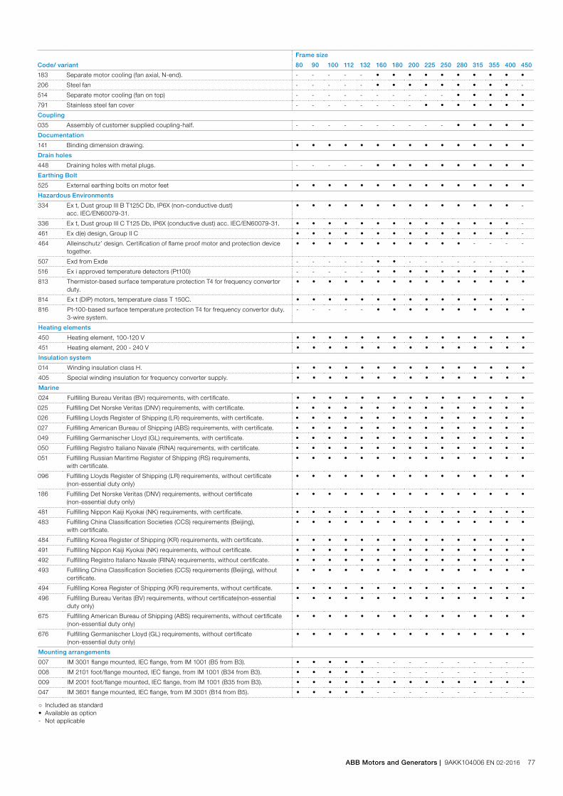
Frame size
Code/ variant 80 90 100 112 132 160 180 200 225 250 280 315 355 400 450
183 Separate motor cooling (fan axial, N-end). - - - - - • • • • • • • • • •
206 Steel fan - - - - - • • • • • • • • • -
514 Separate motor cooling (fan on top) - - - - - - - - - - • • • • •
791 Stainless steel fan cover - - - - - - - - • • • • • • •
Coupling
035 Assembly of customer supplied coupling-half. - - - - - - - - - - • • • • •
Documentation
141 Binding dimension drawing. • • • • • • • • • • • • • • •
Drain holes
448 Draining holes with metal plugs. - - - - - • • • • • • • • • •
Earthing Bolt
525 External earthing bolts on motor feet • • • • • • • • • • • • • • •
Hazardous Environments
334 Ex t, Dust group III B T125C Db, IP6X (non-conductive dust) acc. IEC/EN60079-31.
• • • • • • • • • • • • • • -
336 Ex t, Dust group III C T125 Db, IP6X (conductive dust) acc. IEC/EN60079-31. • • • • • • • • • • • • • • -
461 Ex d(e) design, Group II C • • • • • • • • • • • • • • -
464 Alleinschutz’ design. Certification of flame proof motor and protection device together.
• • • • • • • • • • • - - - -
507 Exd from Exde - - - - - • • - - - - - - - -
516 Ex i approved temperature detectors (Pt100) - - - - - • • • • • • • • • •
813 Thermistor-based surface temperature protection T4 for frequency convertor duty.
• • • • • • • • • • • • • • •
814 Ex t (DIP) motors, temperature class T 150C. • • • • • • • • • • • • • • -
816 Pt-100-based surface temperature protection T4 for frequency convertor duty. 3-wire system.
- - - - - • • • • • • • • • •
Heating elements
450 Heating element, 100-120 V • • • • • • • • • • • • • • •
451 Heating element, 200 - 240 V • • • • • • • • • • • • • • •
Insulation system
014 Winding insulation class H. • • • • • • • • • • • • • • •
405 Special winding insulation for frequency converter supply. • • • • • • • • • • • • • • •
Marine
024 Fulfilling Bureau Veritas (BV) requirements, with certificate. • • • • • • • • • • • • • • •
025 Fulfilling Det Norske Veritas (DNV) requirements, with certificate. • • • • • • • • • • • • • • •
026 Fulfilling Lloyds Register of Shipping (LR) requirements, with certificate. • • • • • • • • • • • • • • •
027 Fulfilling American Bureau of Shipping (ABS) requirements, with certificate. • • • • • • • • • • • • • • •
049 Fulfilling Germanischer Lloyd (GL) requirements, with certificate. • • • • • • • • • • • • • • •
050 Fulfilling Registro Italiano Navale (RINA) requirements, with certificate. • • • • • • • • • • • • • • •
051 Fulfilling Russian Maritime Register of Shipping (RS) requirements, with certificate.
• • • • • • • • • • • • • • •
096 Fulfilling Lloyds Register of Shipping (LR) requirements, without certificate (non-essential duty only)
• • • • • • • • • • • • • • •
186 Fulfilling Det Norske Veritas (DNV) requirements, without certificate (non-essential duty only)
• • • • • • • • • • • • • • •
481 Fulfilling Nippon Kaiji Kyokai (NK) requirements, with certificate. • • • • • • • • • • • • • • •
483 Fulfilling China Classification Societies (CCS) requirements (Beijing), with certificate.
• • • • • • • • • • • • • • •
484 Fulfilling Korea Register of Shipping (KR) requirements, with certificate. • • • • • • • • • • • • • • •
491 Fulfilling Nippon Kaiji Kyokai (NK) requirements, without certificate. • • • • • • • • • • • • • • •
492 Fulfilling Registro Italiano Navale (RINA) requirements, without certificate. • • • • • • • • • • • • • • •
493 Fulfilling China Classification Societies (CCS) requirements (Beijing), without certificate.
• • • • • • • • • • • • • • •
494 Fulfilling Korea Register of Shipping (KR) requirements, without certificate. • • • • • • • • • • • • • • •
496 Fulfilling Bureau Veritas (BV) requirements, without certificate(non-essential duty only)
• • • • • • • • • • • • • • •
675 Fulfilling American Bureau of Shipping (ABS) requirements, without certificate (non-essential duty only)
• • • • • • • • • • • • • • •
676 Fulfilling Germanischer Lloyd (GL) requirements, without certificate (non-essential duty only)
• • • • • • • • • • • • • • •
Mounting arrangements
007 IM 3001 flange mounted, IEC flange, from IM 1001 (B5 from B3). • • • • • - - - - - - - - - -
008 IM 2101 foot/flange mounted, IEC flange, from IM 1001 (B34 from B3). • • • • • - - - - - - - - - -
009 IM 2001 foot/flange mounted, IEC flange, from IM 1001 (B35 from B3). • • • • • • • • • • • • • • •
047 IM 3601 flange mounted, IEC flange, from IM 3001 (B14 from B5). • • • • • - - - - - - - - - -
○ Included as standard• Available as option- Not applicable
ABB Motors and Generators | 9AKK104006 EN 02-2016 77
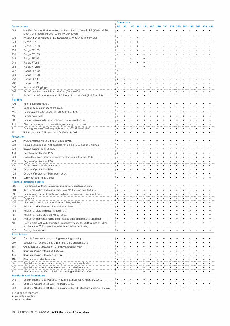
Frame size
Code/ variant 80 90 100 112 132 160 180 200 225 250 280 315 355 400 450
066 Modified for specified mounting position differing from IM B3 (1001), IM B5 (3001), B14 (3601), IM B35 (2001), IM B34 (2101)
• • • • • • • • • • • • • • •
093 IM 3601 flange mounted, IEC flange, from IM 1001 (B14 from B3). • • • • • - - - - - - - - - -
228 Flange FF 130. • • • • - - - - - - - - - - -
229 Flange FT 130. • • • • - - - - - - - - - - -
235 Flange FF 165. ○ • • • • - - - - - - - - - -
236 Flange FT 165. - • • • • - - - - - - - - - -
245 Flange FF 215. - - ○ ○ • - - - - - - - - - -
246 Flange FT 215. - - • • • - - - - - - - - - -
256 Flange FT 265. - - - - • - - - - - - - - - -
257 Flange FF 100. • - - - - - - - - - - - - - -
258 Flange FT 100. • - - - - - - - - - - - - - -
259 Flange FF 115. • • - - - - - - - - - - - - -
260 Flange FT 115. • • - - - - - - - - - - - - -
305 Additional lifting lugs. - - - - - - - - - - • • • • •
309 IM 1001 foot mounted, from IM 3001 (B3 from B5). • • • • • • • - - - - - - - -
311 IM 2001 foot/flange mounted, IEC flange, from IM 3001 (B35 from B5). • • • • • - - - - - - - - - -
Painting
105 Paint thickness report. • • • • • • • • • • • • • • •
114 Special paint color, standard grade • • • • • • • • • • • • • • •
115 Painting system C4M acc. to ISO 12944-2: 1998. • • • • • • • • • • • • • • •
168 Primer paint only. • • • • • • • • • • • • • • •
303 Painted insulation layer on inside of the terminal boxes. • • • • • • • • • • • • • • •
710 Thermally sprayed zink metallizing with acrylic top coat • • • • • • • • • • • • • • •
711 Painting system C5-M very high, acc. to ISO 12944-2:1998 • • • • • • • • • • • • • • •
754 Painting system C5M acc. to ISO 12944-2:1998 • • • • • • • • • • • • • • •
Protection
005 Protective roof, vertical motor, shaft down. • • • • • • • • • • • • • • •
072 Radial seal at D-end. Not possible for 2-pole , 280 and 315 frames • • • • • • • • • • - - - - -
073 Sealed against oil at D-end. • • • • • • • • • • • • - - -
158 Degree of protection IP65. • • • • • • • • • • • • • • -
249 Open deck execution for counter clockwise application, IP56 - - - - - • • • • • • • • • •
250 Degree of protection IP66 • • • • • • • • • • • • • • •
401 Protective roof, horizontal motor. • • • • • • • • • • • • • • •
403 Degree of protection IP56. • • • • • • • • • • • • • • -
434 Degree of protection IP56, open deck. - - - - - • • • • • • • • • •
783 Labyrinth sealing at D-end. • • • • • • • • • • • • ○ ○ ○Rating & instruction plates
002 Restamping voltage, frequency and output, continuous duty. • • • • • • • • • • • • • • •
004 Additional text on std rating plate (max 12 digits on free text line). • • • • • • • • • • • • • • •
095 Restamping output (maintained voltage, frequency), intermittent duty. • • • • • • • • • • • • • • •
126 Tag plate • • • • • • • • • • • • • • •
135 Mounting of additional identification plate, stainless. • • • • • • • • • • • • • • •
139 Additional identification plate delivered loose. • • • • • • • • • • • • • • •
159 Additional plate with text “Made in ....” • • • • • • • • • • • • • • •
161 Additional rating plate delivered loose. • • • • • • • • • • • • • • •
163 Frequency converter rating plate. Rating data according to quotation. • • • • • • • • • • • • • • •
181 Rating plate with ABB standard loadability values for VSD operation. Other auxiliaries for VSD operation to be selected as necessary.
• • • • • • • • • • • • • • •
528 Rating plate sticker • • • • • • • • • • • • • • •
Shaft & rotor
069 Two shaft extensions according to catalog drawings. • • • • • • • • • • • • • • •
070 Special shaft extension at D-End, standard shaft material • • • • • • • • • • • • • • •
155 Cylindrical shaft extension, D-end, without key-way. • • • • • • • • • • • • • • •
164 Shaft extension with closed keyway ○ ○ ○ ○ ○ ○ ○ ○ ○ ○ • • • • -
165 Shaft extension with open keyway • • • • • • • • • • ○ ○ ○ ○ ○410 Shaft material stainless steel • • • • • • • • • • • • • • •
591 Special shaft extension according to customer specification. • • • • • • • • • • • • • • •
600 Special shaft extension at N-end, standard shaft material. • • • • • • • • • • • • • • •
630 Shaft material certificate 3.1/3.2 according to EN10204:2004 - - - - • • • • • • • • • • •
Standards and Regulations
248 Design according to Petronas PTS 33.66.05.31-GEN. February 2010. • • • • • • • • • • • • • - -
251 Shell DEP 33.66.05.31-GEN. February 2012. • • • • • • • • • • • • • • •
252 Shell DEP 33.66.05.31-GEN. February 2012, with standard winding >55 kW. - - - - - - - - - - • - - - -
○ Included as standard• Available as option- Not applicable
78 9AKK104006 EN 02-2016 | ABB Motors and Generators

Frame size
Code/ variant 80 90 100 112 132 160 180 200 225 250 280 315 355 400 450
408 Fulfilling EISA Subtype II efficiency requirements, CC031A. - - - - - • • • • • • • - - -
421 VIK design (Verband der Industriellen Energie- und Kraftwirtschaft e.V.). • • • • • • • • • • • • • • -
505 VIK design with ABB standard shaft dimensions (Verband der Industriellen Energie- und Kraftwirtschaft e.V.).
• • • • • • • • • • • • • • •
540 China energy label • • • • • • • • • • • • • - -
541 Inmetro certification • • • • • • • • • • • • • • -
543 Australian MEPS • • • • • • • • • • • • • - -
544 Australian HE MEPS - - - - - • • • • • • • - - -
547 Certificate of conformity according TR-CU 012/2011 for customs union RU, KZ, BY.
• • • • • • • • • • • • • • •
782 Fulfilling CQST Certification requirements (China) • • • • • • • • • • • • • • •
Stator winding temperature sensors
121 Bimetal detectors, break type (NCC), (3 in series), 130 ºC, in stator winding • • • • • • • • • • • • • • •
122 Bimetal detectors, break type (NCC), (3 in series), 150 ºC, in stator winding • • • • • • • • • • • • • • •
123 Bimetal detectors, break type (NCC), (3 in series), 170 ºC, in stator winding - - - - - - - - - - • • • • •
125 Bimetal detectors, break type (NCC), (2x3 in series), 150 ºC, in stator winding • • • • • • • • • • • • • • •
127 Bimetal detectors, break type (NCC), (3 in series, 130 ºC & 3 in series, 150 ºC), in stator winding
• • • • • • • • • • • • • • •
328 PTC - thermistors (3 in series), 120ºC, in stator winding • • • • • • • • • • • • • • •
435 PTC - thermistors (3 in series), 130 ºC, in stator winding • • • • • • • • • • • • • • •
439 PTC - thermistors (2x3 in series), 150 ºC, in stator winding • • • • • • • • • • • • • • •
441 PTC - thermistors (3 in series, 130 ºC & 3 in series, 150 ºC), in stator winding • • • • • • • • • • • • • • •
445 Pt100 2-wire in stator winding, 1 per phase • • • • • • • • • • • • • • •
446 Pt100 2-wire in stator winding, 2 per phase - - - - - • • • • • • • • • •
502 Pt100 3-wire in stator winding, 1 per phase - - - - - • • • • • • • • • •
503 Pt100 3-wire in stator winding, 2 per phase - - - - - • • • • • • • • • •
511 PTC thermistors (2 x 3 in series), 130 ºC, in stator winding • • • • • • • • • • • • • • •
Terminal box
019 Larger than standard terminal box. - - - - - - - - - - • - - - -
021 Terminal box LHS (seen from D-end). - - - - - • • - - - - - - - -
022 Cable entry LHS (seen from D-end). • • • • • • • • • • • • • • •
157 Terminal box degree of protection IP65. • • • • • • • • • • • • • • -
180 Terminal box RHS (seen from D-end). - - - - - • • - - - - - - - -
230 Standard metal cable gland • • • • • • • • • • • • • - -
277 Cable sealing end unit, size small for C-opening - - - - - - - - - - • - - - -
278 Cable sealing end unit, size medium for D-opening - - - - - - - - - - - • • • •
279 Cable sealing end unit, size large for D-opening - - - - - - - - - - - • • • •
292 Adapter C-C - - - - - - - - - - • - - - -
293 Adapter D-D - - - - - - - - - - - • • • -
294 Adapter E-D - - - - - - - - - - - • • • •
295 Adapter E-2D - - - - - - - - - - - • • • •
351 Terminal block turned according to cable entry - - - - - - - - - - • • - • •
380 Separate terminal box for temperature detectors, std. material - - - - - • • • • • • • • • •
413 Extended cable connection, no terminal box. - - - - - • • • • • • • • • •
418 Separate terminal box for auxiliaries, standard material. - - - - - • • • • • • • • • •
466 Terminal box at N-end. - - - - - - - • • • • • • • •
468 Cable entry from D-end. • • • • • • • • • • • • - - -
469 Cable entry from N-end. • • • • • • • • • • • • - - -
526 Existing cable entries plugged ○ ○ ○ ○ ○ ○ ○ ○ ○ ○ ○ ○ ○ • •
553 Terminal box degree of protection IP66. • • • • • • • • • • • • • • -
554 Painted steel flange for cable glands drilled and tapped according to order. • • • • • • • • • • • • • • •
555 Aluminum flange for cable glands drilled and tapped according to order. • • • • • • • • • • • • • • •
557 Nickel plated cable glands mounted according to order. • • • • • • • • • • • • • • •
567 Separate terminal box material: cast Iron - - - - - ○ ○ • • • • • • • •
568 Separate terminal box for heating elements, std. material - - - - - • • • • • • • • • •
624 Prepared for BSP cable glands. • • • • • • • • • • • • • • -
727 Stainless steel flange for cable glands drilled and tapped according to order. • • • • • • • • • • • • • • •
729 Aluminum non-drilled flange for cable glands • • • • • • • • • • • • • • •
730 Prepared for NPT cable glands. • • • • • • • • • • • • • • •
731 Two standard metal cable glands • • • • • • • • • • • • • • •
734 Standard cable gland, Ex d IIC, armoured cable. • • • • • • • • • • • • • • •
735 Standard cable gland, Ex d IIC, non-armoured cable. • • • • • • • • • • • • • • •
743 Painted non-drilled flange in steel for cable glands • • • • • • • • • • • • • • •
744 Stainless steel non-drilled flange for cable glands. • • • • • • • • • • • • • • •
○ Included as standard• Available as option- Not applicable
ABB Motors and Generators | 9AKK104006 EN 02-2016 79
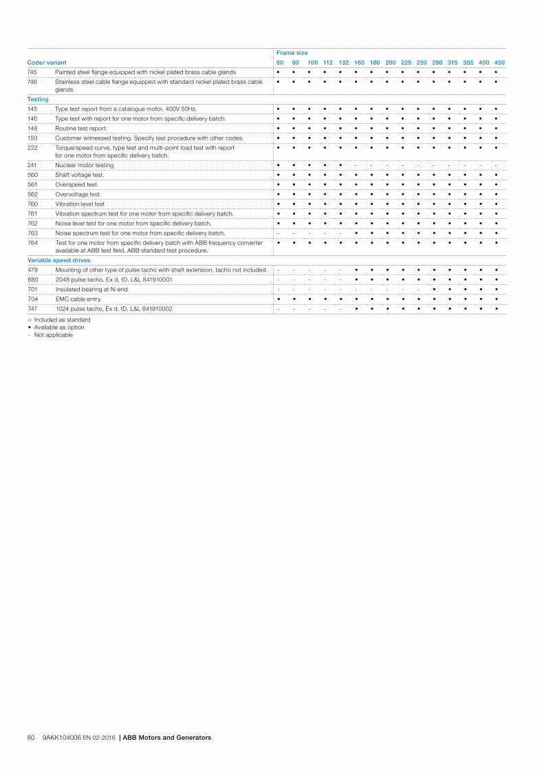
Frame size
Code/ variant 80 90 100 112 132 160 180 200 225 250 280 315 355 400 450
745 Painted steel flange equipped with nickel plated brass cable glands • • • • • • • • • • • • • • •
746 Stainless steel cable flange equipped with standard nickel plated brass cable glands
• • • • • • • • • • • • • • •
Testing
145 Type test report from a catalogue motor, 400V 50Hz. • • • • • • • • • • • • • • •
146 Type test with report for one motor from specific delivery batch. • • • • • • • • • • • • • • •
148 Routine test report. • • • • • • • • • • • • • • •
150 Customer witnessed testing. Specify test procedure with other codes. • • • • • • • • • • • • • • •
222 Torque/speed curve, type test and multi-point load test with report for one motor from specific delivery batch.
• • • • • • • • • • • • • • •
241 Nuclear motor testing • • • • • - - - - - - - - - -
560 Shaft voltage test. • • • • • • • • • • • • • • •
561 Overspeed test. • • • • • • • • • • • • • • •
562 Overvoltage test. • • • • • • • • • • • • • • •
760 Vibration level test • • • • • • • • • • • • • • •
761 Vibration spectrum test for one motor from specific delivery batch. • • • • • • • • • • • • • • •
762 Noise level test for one motor from specific delivery batch. • • • • • • • • • • • • • • •
763 Noise spectrum test for one motor from specific delivery batch. - - - - - • • • • • • • • • •
764 Test for one motor from specific delivery batch with ABB frequency converter available at ABB test field. ABB standard test procedure.
• • • • • • • • • • • • • • •
Variable speed drives
479 Mounting of other type of pulse tacho with shaft extension, tacho not included. - - - - - • • • • • • • • • •
680 2048 pulse tacho, Ex d, tD, L&L 841910001 - - - - - • • • • • • • • • •
701 Insulated bearing at N-end. - - - - - - - - - - • • • • •
704 EMC cable entry. • • • • • • • • • • • • • • •
747 1024 pulse tacho, Ex d, tD, L&L 841910002 - - - - - • • • • • • • • • •
○ Included as standard• Available as option- Not applicable
80 9AKK104006 EN 02-2016 | ABB Motors and Generators
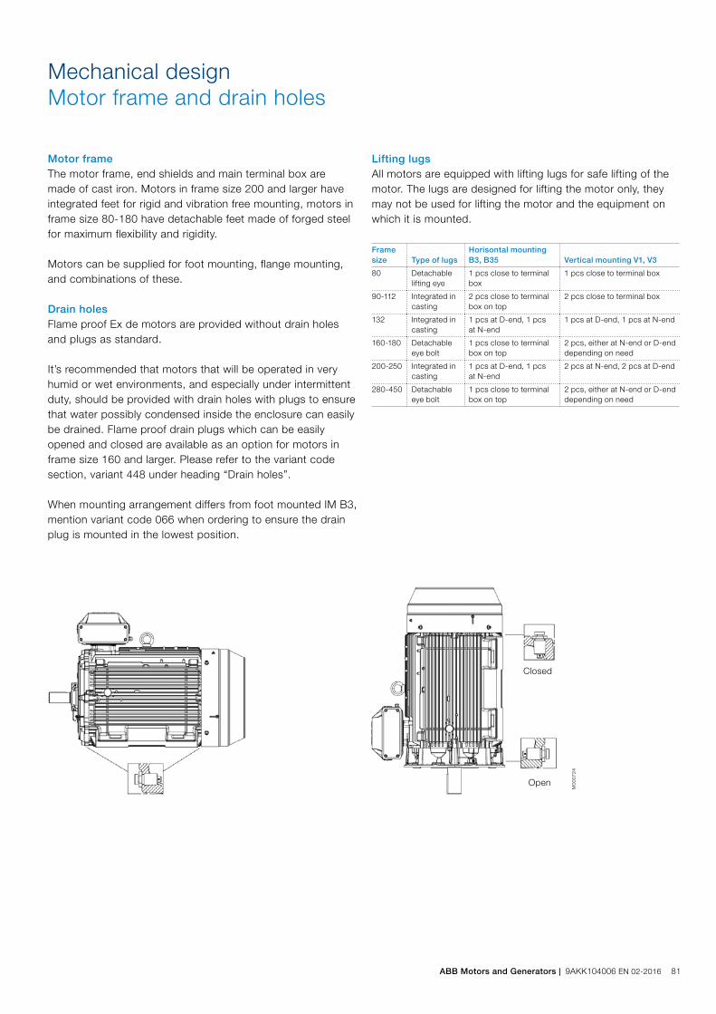
Mechanical designMotor frame and drain holes
M00
0724
Closed
Open
Motor frameThe motor frame, end shields and main terminal box are made of cast iron. Motors in frame size 200 and larger have integrated feet for rigid and vibration free mounting, motors in frame size 80-180 have detachable feet made of forged steel for maximum flexibility and rigidity.
Motors can be supplied for foot mounting, flange mounting, and combinations of these.
Drain holesFlame proof Ex de motors are provided without drain holes and plugs as standard.
It’s recommended that motors that will be operated in very humid or wet environments, and especially under intermittent duty, should be provided with drain holes with plugs to ensure that water possibly condensed inside the enclosure can easily be drained. Flame proof drain plugs which can be easily opened and closed are available as an option for motors in frame size 160 and larger. Please refer to the variant code section, variant 448 under heading “Drain holes”.
When mounting arrangement differs from foot mounted IM B3, mention variant code 066 when ordering to ensure the drain plug is mounted in the lowest position.
Lifting lugsAll motors are equipped with lifting lugs for safe lifting of the motor. The lugs are designed for lifting the motor only, they may not be used for lifting the motor and the equipment on which it is mounted.
Frame size Type of lugs
Horisontal mounting B3, B35 Vertical mounting V1, V3
80 Detachable lifting eye
1 pcs close to terminal box
1 pcs close to terminal box
90-112 Integrated in casting
2 pcs close to terminal box on top
2 pcs close to terminal box
132 Integrated in casting
1 pcs at D-end, 1 pcs at N-end
1 pcs at D-end, 1 pcs at N-end
160-180 Detachable eye bolt
1 pcs close to terminal box on top
2 pcs, either at N-end or D-end depending on need
200-250 Integrated in casting
1 pcs at D-end, 1 pcs at N-end
2 pcs at N-end, 2 pcs at D-end
280-450 Detachable eye bolt
1 pcs close to terminal box on top
2 pcs, either at N-end or D-end depending on need
ABB Motors and Generators | 9AKK104006 EN 02-2016 81

Heating elements
Heating elements are installed on stator winding coil heads to keep the winding free of corrosion in humid conditions. The power of the heating elements is shown in the table. You can order heating elements with variant code 450 or 451.
Motor size 80 90 100 112 132 160 180
Power (W) 25 25 25 25 25 25 25
Motor size 200 225 250 280 315 355 400 450
Power (W) 25 60 60 60 2x60 2x60 2x60 2x100
Motors for marine applications mounted on open deck may have heating element powers differing from the ones shown in this table.
82 9AKK104006 EN 02-2016 | ABB Motors and Generators
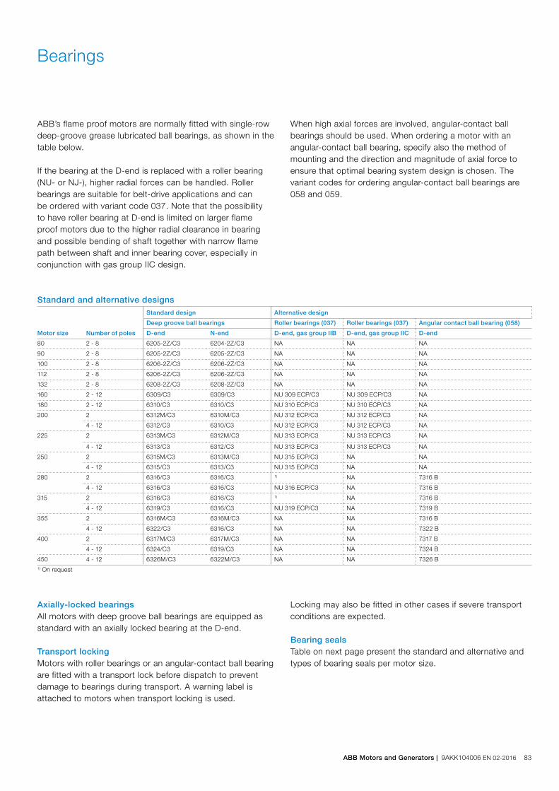
Bearings
ABB’s flame proof motors are normally fitted with single-rowdeep-groove grease lubricated ball bearings, as shown in the table below.
If the bearing at the D-end is replaced with a roller bearing (NU- or NJ-), higher radial forces can be handled. Roller bearings are suitable for belt-drive applications and can be ordered with variant code 037. Note that the possibility to have roller bearing at D-end is limited on larger flame proof motors due to the higher radial clearance in bearing and possible bending of shaft together with narrow flame path between shaft and inner bearing cover, especially in conjunction with gas group IIC design.
Motor size Number of poles
Standard design Alternative design
Deep groove ball bearings Roller bearings (037) Roller bearings (037) Angular contact ball bearing (058)
D-end N-end D-end, gas group IIB D-end, gas group IIC D-end
80 2 - 8 6205-2Z/C3 6204-2Z/C3 NA NA NA
90 2 - 8 6205-2Z/C3 6205-2Z/C3 NA NA NA
100 2 - 8 6206-2Z/C3 6206-2Z/C3 NA NA NA
112 2 - 8 6206-2Z/C3 6206-2Z/C3 NA NA NA
132 2 - 8 6208-2Z/C3 6208-2Z/C3 NA NA NA
160 2 - 12 6309/C3 6309/C3 NU 309 ECP/C3 NU 309 ECP/C3 NA
180 2 - 12 6310/C3 6310/C3 NU 310 ECP/C3 NU 310 ECP/C3 NA
200 2 6312M/C3 6310M/C3 NU 312 ECP/C3 NU 312 ECP/C3 NA
4 - 12 6312/C3 6310/C3 NU 312 ECP/C3 NU 312 ECP/C3 NA
225 2 6313M/C3 6312M/C3 NU 313 ECP/C3 NU 313 ECP/C3 NA
4 - 12 6313/C3 6312/C3 NU 313 ECP/C3 NU 313 ECP/C3 NA
250 2 6315M/C3 6313M/C3 NU 315 ECP/C3 NA NA
4 - 12 6315/C3 6313/C3 NU 315 ECP/C3 NA NA
280 2 6316/C3 6316/C3 1) NA 7316 B
4 - 12 6316/C3 6316/C3 NU 316 ECP/C3 NA 7316 B
315 2 6316/C3 6316/C3 1) NA 7316 B
4 - 12 6319/C3 6316/C3 NU 319 ECP/C3 NA 7319 B
355 2 6316M/C3 6316M/C3 NA NA 7316 B
4 - 12 6322/C3 6316/C3 NA NA 7322 B
400 2 6317M/C3 6317M/C3 NA NA 7317 B
4 - 12 6324/C3 6319/C3 NA NA 7324 B
450 4 - 12 6326M/C3 6322M/C3 NA NA 7326 B1) On request
Axially-locked bearingsAll motors with deep groove ball bearings are equipped as standard with an axially locked bearing at the D-end.
Transport lockingMotors with roller bearings or an angular-contact ball bearing are fitted with a transport lock before dispatch to prevent damage to bearings during transport. A warning label is attached to motors when transport locking is used.
Standard and alternative designs
When high axial forces are involved, angular-contact ball bearings should be used. When ordering a motor with an angular-contact ball bearing, specify also the method of mounting and the direction and magnitude of axial force to ensure that optimal bearing system design is chosen. The variant codes for ordering angular-contact ball bearings are 058 and 059.
Locking may also be fitted in other cases if severe transport conditions are expected.
Bearing sealsTable on next page present the standard and alternative and types of bearing seals per motor size.
ABB Motors and Generators | 9AKK104006 EN 02-2016 83
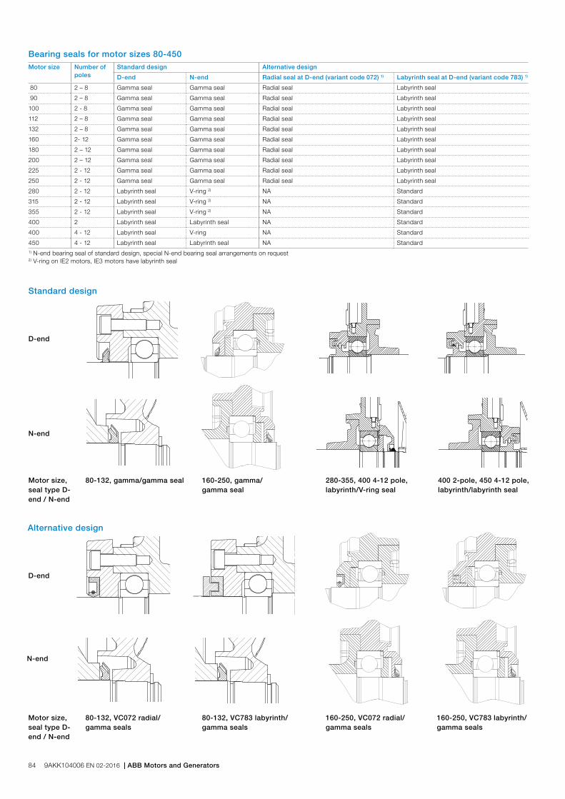
Standard design
Motor size Number ofpoles
Standard design Alternative design
D-end N-end Radial seal at D-end (variant code 072) 1) Labyrinth seal at D-end (variant code 783) 1)
80 2 – 8 Gamma seal Gamma seal Radial seal Labyrinth seal
90 2 – 8 Gamma seal Gamma seal Radial seal Labyrinth seal
100 2 - 8 Gamma seal Gamma seal Radial seal Labyrinth seal
112 2 – 8 Gamma seal Gamma seal Radial seal Labyrinth seal
132 2 – 8 Gamma seal Gamma seal Radial seal Labyrinth seal
160 2- 12 Gamma seal Gamma seal Radial seal Labyrinth seal
180 2 – 12 Gamma seal Gamma seal Radial seal Labyrinth seal
200 2 – 12 Gamma seal Gamma seal Radial seal Labyrinth seal
225 2 - 12 Gamma seal Gamma seal Radial seal Labyrinth seal
250 2 - 12 Gamma seal Gamma seal Radial seal Labyrinth seal
280 2 - 12 Labyrinth seal V-ring 2) NA Standard
315 2 - 12 Labyrinth seal V-ring 2) NA Standard
355 2 - 12 Labyrinth seal V-ring 2) NA Standard
400 2 Labyrinth seal Labyrinth seal NA Standard
400 4 - 12 Labyrinth seal V-ring NA Standard
450 4 - 12 Labyrinth seal Labyrinth seal NA Standard1) N-end bearing seal of standard design, special N-end bearing seal arrangements on request2) V-ring on IE2 motors, IE3 motors have labyrinth seal
D-end
N-end
Motor size,seal type D-end / N-end
80-132, gamma/gamma seal 160-250, gamma/gamma seal
280-355, 400 4-12 pole, labyrinth/V-ring seal
400 2-pole, 450 4-12 pole, labyrinth/labyrinth seal
Bearing seals for motor sizes 80-450
Alternative design
D-end
N-end
Motor size, seal type D-end / N-end
80-132, VC072 radial/gamma seals
80-132, VC783 labyrinth/gamma seals
160-250, VC072 radial/gamma seals
160-250, VC783 labyrinth/gamma seals
84 9AKK104006 EN 02-2016 | ABB Motors and Generators

Bearing life and lubricationThe nominal life L10h of a bearing is defined according to ISO 281 as the number of operating hours achieved or exceeded by 90 % of identical bearings in a large test series under specified conditions. 50 % of bearings achieve at least five times this lifetime.
The calculated bearing life L10h for power transmission by means of coupling is for horizontally mounted motors in sizes up to 315 ≥ 100,000 hours.
LubricationOn delivery, motors in frame size 160 and above are pre-lubricated with high-quality grease. Before first start-up, see instructions for re-lubrication and recommended grease in the installation, operation, maintenance and safety manual for low voltage motors for explosive atmospheres delivered together with the motor, or see the lubrication plate on the motor.
Motors with bearings greased for lifeMotors in frame sizes 80-132 are equipped with bearings greased for life, while this is available as an option for frame sizes 160-250. Bearings are lubricated with high-quality, high-temperature grease. Bearing types are stated on the rating plate.
The approximate lifetime of bearings in four-pole motors is about 40 0000 duty hours. Lifetime is subject to the load conditions of the application run by the motor.
Motors with re-lubrication nipplesIn frame sizes 160-450, the bearing system is provided with valve discs to ease lubrication. Motors are lubricated while running. The grease outlet opening has closing valves at both ends. These should be opened before greasing and closed 1-2 hours after re-greasing. This ensures that the construction is tight and bearings remain dust- and dirt-free.
A grease-collection method can be used optionally.
The following tables show lubrication intervals according to the L1 principle for various nominal speeds in 25 °C ambient temperature. These values apply to horizontally mounted motors (B3) with 80 °C bearing temperature and high-quality grease containing lithium-complex soap and mineral or PAO-oil.
Lubrication intervals in duty hours for ball bearings
Amount Amount Speed Speed Speed Speed Speed SpeedFrame of grease of grease 3600 3000 1800 1500 1000 500-900size g/bearing g/N-end r/min r/min r/min r/min r/min r/min
Ball bearings
Lubrication intervals in duty hours
160 13 13 7100 8900 14300 16300 20500 21600
180 15 15 6100 7800 13100 15100 19400 20500
200 20 15 4300 5900 11000 13000 17300 18400
225 23 20 3600 5100 10100 12000 16400 17500
250 30 23 2400 3700 8500 10400 14700 15800
280 35 35 1900 3200 - - - -
280 40 40 - - 7800 9600 13900 15000
315 35 35 1900 3200 - - - -
315 55 40 - - 5900 7600 11800 12900
355 35 35 1900 3200 - - - -
355 70 40 - - 4000 5600 9600 10700
400 40 40 1500 2700 - - - -
400 85 55 - - 3200 4700 8600 9700
450 95 70 - - 2500 3900 7700 8700
Amount Amount Speed Speed Speed Speed Speed SpeedFrame of grease of grease Output 3600 3000 Output 1800 1500 Output 1000 Output 500-900size g/bearing g/N-end kW r/min r/min kW r/min r/min kW r/min kW r/min
Roller bearings
Lubrication intervals in duty hours
160 13 13 all 3600 4500 all 7200 8100 all 10300 all 10800
180 15 15 3000 3900 all 6600 7500 all 9700 all 10200
200 20 15 2100 3000 all 5500 6500 all 8600 all 9200
225 23 20 1800 1600 all 5100 6000 all 8200 all 8700
250 30 23 1200 1900 all 4200 5200 all 7300 all 7900
280 40 40 - - all 4000 5300 all 7000 all 8500
315 55 40 - - all 2900 3800 all 5900 all 6500
Lubrication intervals in duty hours for roller bearings
ABB Motors and Generators | 9AKK104006 EN 02-2016 85
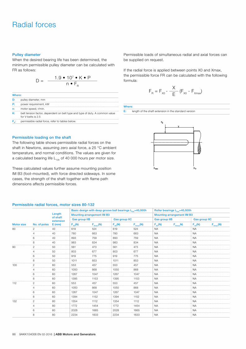
Radial forces
Pulley diameterWhen the desired bearing life has been determined, the minimum permissible pulley diameter can be calculated with FR as follows:
D =1.9 • 107 • K • P
n • FR
Where:
D: pulley diameter, mm
P: power requirement, kW
n: motor speed, r/min.
K: belt tension factor, dependent on belt type and type of duty. A common value for V-belts is 2.5
FR: permissible radial force, refer to tables below.
Permissible loading on the shaftThe following table shows permissible radial forces on the shaft in Newtons, assuming zero axial force, a 25 °C ambient temperature, and normal conditions. The values are given for a calculated bearing life L10h of 40 000 hours per motor size.
These calculated values further assume mounting position IM B3 (foot-mounted), with force directed sideways. In some cases, the strength of the shaft together with flame path dimensions affects permissible forces.
FR = FX0 -
X (FX0 - FXmax)E
Where:
E: length of the shaft extension in the standard version
Permissible radial forces, motor sizes 80-132
Permissible loads of simultaneous radial and axial forces can be supplied on request.
If the radial force is applied between points X0 and Xmax, the permissible force FR can be calculated with the following formula:
Motor size No. of poles
Length of shaft extension E (mm)
Basic design with deep groove ball bearings L10h=40,000h Roller bearings L10h=40,000h
Mounting arrangement IM B3 Mounting arrangement IM B3
Gas group IIB Gas group IIC Gas group IIB Gas group IIC
FX0(N) FXmax(N) FX0(N) FXmax(N) FX0(N) FXmax(N) FX0(N) FXmax(N)
80 2 40 619 524 619 524 NA NA
4 40 780 663 780 663 NA NA
6 40 893 759 893 759 NA NA
8 40 983 834 983 834 NA NA
90 2 50 561 473 561 473 NA NA
4 50 803 677 803 677 NA NA
6 50 919 775 919 775 NA NA
8 50 1011 853 1011 853 NA NA
100 2 60 553 457 553 457 NA NA
4 60 1050 868 1050 868 NA NA
6 60 1267 1047 1267 1047 NA NA
8 60 1395 1153 1395 1153 NA NA
112 2 60 553 457 553 457 NA NA
4 60 1050 868 1050 868 NA NA
6 60 1267 1047 1267 1047 NA NA
8 60 1394 1152 1394 1152 NA NA
132 2 80 1354 1112 1354 1112 NA NA
4 80 1772 1454 1772 1454 NA NA
6 80 2028 1665 2028 1665 NA NA
8 80 2234 1833 2234 1833 NA NA
86 9AKK104006 EN 02-2016 | ABB Motors and Generators

Permissible radial forces, motor sizes 160 to 450
Motor size Poles
Length of shaft extension E (mm)
Basic design with deep groove ball bearings L10h=40,000h Roller bearings L10h=40,000h
Mounting arrangement IM B3 Mounting arrangement IM B3
Gas group IIB Gas group IIC Gas group IIB Gas group IIC
FX0(N) FXmax(N) FX0(N) FXmax(N) FX0(N) FXmax(N) FX0(N) FXmax(N)
160 ML_ 2 110 2530 2120 2530 2120 6400 1800 6400 1800
4 110 3180 2670 3180 2670 7600 1800 7600 1800
6 110 3650 3040 3650 3040 7600 1800 7600 1800
8 110 4020 3040 4020 3040 7600 1800 7600 1800
180 ML_ 2 110 2900 2440 2900 2440 6970 2700 6970 2700
4 110 3660 3080 3660 3080 8500 2700 8500 2700
6 110 4190 3520 4190 3520 8500 2700 8500 2700
8 110 4620 3880 4620 3880 8500 2700 8500 2700
200 ML_ 2 110 3830 3150 3830 3150 9510 7000 9510 4200
4 110 4820 3980 4820 3980 11710 7000 11710 4200
6 110 5520 4550 5520 4550 13230 7000 13230 4200
8 110 6080 5000 6080 5000 14420 7000 14420 4200
225 SM_ 2 110 4350 3660 4350 3660 11650 7000 9300 3000
4 140 5490 2800 5490 2800 14340 7200 9300 2200
6 140 6280 2800 6280 2800 16190 7200 9300 2200
8 140 6920 2800 6920 2800 17300 7200 9300 2200
250 SM_ 2 140 5390 4350 5390 4350 15420 6700 NA
4 140 6790 5480 6790 5480 18980 9200 NA
6 140 7760 6270 3000 2800 21000 9200 NA
8 140 8550 6900 3000 2800 21000 9200 NA
280 SM_ 2 140 5835 4900 1) 16500 6000 NA
4 140 7360 6110 1) 20100 9200 NA
6 140 8425 6980 1) 22690 9200 NA
8 140 9165 7700 1) 24740 9200 NA
315 SM_ 2 140 5815 4960 1) 16540 6000 NA
4 170 9025 7470 1) 26590 9600 NA
6 170 10310 8530 1) 30030 10160 NA
8 170 11370 9410 1) 32740 10105 NA
315 ML_ 2 140 5855 5080 1) 16705 6205 NA
4 170 8980 7590 1) 26550 13705 NA
6 170 10255 8665 1) 29970 13710 NA
8 170 11335 9385 1) 32730 9945 NA
315 LK_ 2 140 5860 5195 1) 16885 6080 NA
4 170 9185 7945 1) 27225 13475 NA
6 170 10475 9060 1) 30735 13500 NA
355 SM_ 2 140 5790 5085 1) NA NA
4 210 11930 9890 1) NA NA
6 210 11930 9890 1) NA NA
8 210 11930 9890 1) NA NA
355 ML_ 2 140 5770 5120 1) NA NA
4 210 11980 10090 1) NA NA
6 210 11980 10090 1) NA NA
8 210 11980 10090 1) NA NA
355 LK_ 2 140 5500 5000 1) NA NA
4 210 12050 10450 1) NA NA
6 210 12050 10450 1) NA NA
8 210 12050 10450 1) NA NA
400 L_ 2 170 1) 1) NA NA
4 210 1) 1) NA NA
6 210 1) 1) NA NA
8 210 1) 1) NA NA
400 LK_ 2 170 1) 1) NA NA
4 210 1) 1) NA NA
6 210 1) 1) NA NA
8 210 1) 1) NA NA
450 L_ 4 210 1) 1) NA NA
6 210 1) 1) NA NA
8 210 1) 1) NA NA1) only allowed for direct coupling duty
ABB Motors and Generators | 9AKK104006 EN 02-2016 87
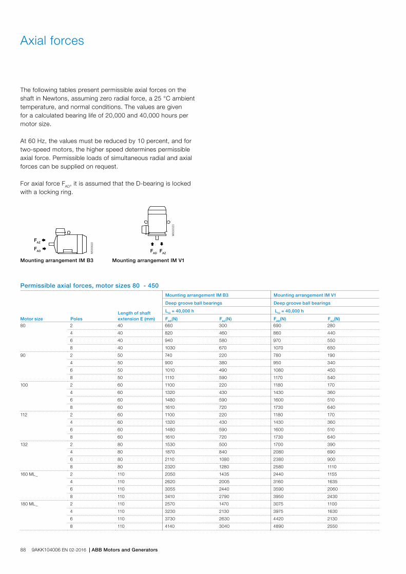
Axial forces
The following tables present permissible axial forces on the shaft in Newtons, assuming zero radial force, a 25 °C ambient temperature, and normal conditions. The values are given for a calculated bearing life of 20,000 and 40,000 hours per motor size.
At 60 Hz, the values must be reduced by 10 percent, and for two-speed motors, the higher speed determines permissible axial force. Permissible loads of simultaneous radial and axial forces can be supplied on request.
For axial force FAD, it is assumed that the D-bearing is locked with a locking ring.
Motor size PolesLength of shaft extension E (mm)
Mounting arrangement IM B3 Mounting arrangement IM V1
Deep groove ball bearings Deep groove ball bearings
L10 = 40,000 h L10 = 40,000 h
FAD(N) FAZ(N) FAD(N) FAZ(N)
80 2 40 660 300 690 280
4 40 820 460 860 440
6 40 940 580 970 550
8 40 1030 670 1070 650
90 2 50 740 220 780 190
4 50 900 380 950 340
6 50 1010 490 1080 450
8 50 1110 590 1170 540
100 2 60 1100 220 1180 170
4 60 1320 430 1430 360
6 60 1480 590 1600 510
8 60 1610 720 1730 640
112 2 60 1100 220 1180 170
4 60 1320 430 1430 360
6 60 1480 590 1600 510
8 60 1610 720 1730 640
132 2 80 1530 500 1700 390
4 80 1870 840 2080 690
6 80 2110 1080 2380 900
8 80 2320 1280 2580 1110
160 ML_ 2 110 2050 1435 2440 1155
4 110 2620 2005 3160 1635
6 110 3055 2440 3590 2060
8 110 3410 2790 3950 2430
180 ML_ 2 110 2570 1470 3075 1100
4 110 3230 2130 3975 1630
6 110 3730 2630 4420 2130
8 110 4140 3040 4890 2550
Permissible axial forces, motor sizes 80 - 450
Ç
FAD
M00
0023
È
FAZFAD Æ
M00
0022
FAZ Å
Mounting arrangement IM B3 Mounting arrangement IM V1
88 9AKK104006 EN 02-2016 | ABB Motors and Generators
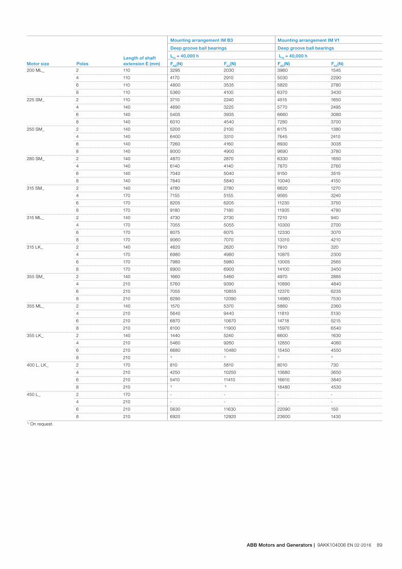
Motor size PolesLength of shaft extension E (mm)
Mounting arrangement IM B3 Mounting arrangement IM V1
Deep groove ball bearings Deep groove ball bearings
L10 = 40,000 h L10 = 40,000 h
FAD(N) FAZ(N) FAD(N) FAZ(N)
200 ML_ 2 110 3295 2030 3960 1545
4 110 4170 2910 5030 2290
6 110 4800 3535 5820 2780
8 110 5360 4100 6370 3430
225 SM_ 2 110 3710 2240 4515 1650
4 140 4690 3225 5770 2495
6 140 5405 3935 6660 3080
8 140 6010 4540 7280 3700
250 SM_ 2 140 5200 2100 6175 1380
4 140 6400 3310 7645 2410
6 140 7260 4160 8930 3035
8 140 8000 4900 9690 3780
280 SM_ 2 140 4870 2870 6330 1650
4 140 6140 4140 7870 2760
6 140 7040 5040 9150 3515
8 140 7840 5840 10040 4150
315 SM_ 2 140 4780 2780 6620 1270
4 170 7155 5155 9565 3240
6 170 8205 6205 11230 3750
8 170 9180 7180 11935 4780
315 ML_ 2 140 4730 2730 7210 940
4 170 7055 5055 10300 2700
6 170 8075 6075 12330 3070
8 170 9060 7070 13310 4210
315 LK_ 2 140 4620 2620 7910 320
4 170 6980 4980 10875 2300
6 170 7980 5980 13005 2565
8 170 8900 6900 14100 3450
355 SM_ 2 140 1660 5460 4970 2885
4 210 5760 9390 10890 4840
6 210 7055 10855 12370 6235
8 210 8290 12090 14980 7530
355 ML_ 2 140 1570 5370 5860 2360
4 210 5640 9440 11810 5130
6 210 6870 10670 14718 5215
8 210 8100 11900 15970 6540
355 LK_ 2 140 1440 5240 6600 1630
4 210 5460 9260 12850 4080
6 210 6680 10480 15450 4550
8 210 1) 1) 1) 1)
400 L, LK_ 2 170 810 5810 8010 730
4 210 4250 10250 13680 3650
6 210 5410 11410 16610 3840
8 210 1) 1) 18480 4530
450 L_ 2 170 - - - -
4 210 - - - -
6 210 5630 11630 22090 150
8 210 6920 12920 23600 14301) On request.
ABB Motors and Generators | 9AKK104006 EN 02-2016 89
Terminal boxStandard terminal box
Protection and mounting optionsThe degree of protection for the standard terminal box is IP 55. It complies with the requirements of the protection method ‘e’ increased safety and prevents all ignition sources such as sparks, excessive over hating etc. The features of the terminal box are: No self loosening terminals, compliance with creepage and clearance distances as defined in standard for increased safety protection.
By default, terminal boxes are mounted on top of the motor at D-end. Side mounted terminal box is possible in frame sizes 160 and 180. Mounting at N-end is also possible for the larger frame sizes. Please refer to the variant code section for more details.
TurnabilityThe standard terminal boxes for motor sizes 80-250 can be turned 4*90°and in sizes 280-450 2*180° after delivery. For sizes 280-450 is also mounting of terminal box with opening towards D or N-end possible using the relevant variant codes when ordering.
Cable entriesTerminal box is provided as standard with tapped holes for cable glands, no cable glands are included as standard, the entry holes are closed with Ex e approved blanking plugs made of nickel plated brass. Very large motors have angle adapters and cable sealing units as standard. Please refer to the table on next page for further information about amount and size of threaded holes, plugs and cable sealing units provided as standard.
Different types of cable glands are available as option, suitable for either armoured and non-armoured cables, please refer to the Terminal box alternatives section for more details.
Cable type and terminationsTerminations are suitable for copper and aluminum cables (Al- cables on request for motor sizes 80 to 250). Cables are connected to terminals by cable lugs, which are not included in the delivery.
Earthing boltsThe motors are as standard provided with at least one earthing bolt inside the terminal box and another on the frame. The earthing bolt on the frame is located on top close to the terminal box for easy access from either side of the motor. As an option can also earting bolts on the feet be provided, please refer to variant code section.
OrderingTo ensure the delivery of desired terminations and cable entries for the motor, state the cable type, quantity, size, outer diameter and possibly type of cable glands needed when ordering.
See section Variant codes for all options available.
90 9AKK104006 EN 02-2016 | ABB Motors and Generators

Standard deliveryStandard delivery if no other information is provided. Note: For other network voltages, contact your ABB sales office.
Cable entries for supply cables
Motor size Pole numberTerminal box type
Size of gland plate opening on terminal box
45° angle adapter
Gland plate with threaded holes, amount and size, holes plugged
Cable sealing end unit, size
Max. connect- able core cross-section mm2/phase
Number and size of terminal bolts
IE2 motors
80 - 90 2-8 25 B - 1x M25x1.5 - 1x10 6x M5
100 - 132 2-8 25 B - 2x M32x1.5 - 1x10 6x M5
160 - 180 2-8 63 2x B - 2x M40x1.5 - 1x35 6x M6
200 - 250 2-8 160 C - 2x M50x1.5 - 1x70 6x M10
280 SM_ 2-8 210 C - 2x M63x1.5 - 2x150 6x M12
315 SM_, ML_ 2-8 370 D - 2x M63x1.5 - 2x240 6x M12
355 SMA - SMC 2-4 750 E E-D - Medium 4x240 6x M12
355 SMA, SMB 6-8 370 D - 2x M63x1.5 - 2x240 6x M12
355 SMC 6 750 E E-D - Medium 4x240 6x M12
355 SMC 8 370 D - 2x M63x1.5 - 2x240 6x M12
355 ML_, LK_ 2-4 750 E E-D - Large 4x240 6x M12
355 ML_, LK_ 6-8 750 E E-D - Medium 4x240 6x M12
400 2-6 750 E E-D - Large 4x240 6x M12
400 8 750 E E-D - Medium 4x240 6x M12
450 4-8 1200 E E-2D - 2xLarge 6x240 12x M12
IE3 motors
160 - 180 2-8 63 2x B - 2x M40x1.5 - 1x35 6x M6
200 - 250 2-8 160 C - 2x M50x1.5 - 1x70 6x M10
280 2-8 210 C - 2x M63x1.5 - 2x150 6x M12
315 2-8 370 D - 2x M63x1.5 - 2x240 6x M12
355 SM_ 2-4 750 E E-D - Medium 4x240 6x M12
355 SM_ 6 370 D - 2x M63x1.5 - 2x240 6x M12
355 ML_, LK_ 2-6 750 E E-D - Medium 4x240 6x M12
Auxiliary cable entries
80 - 132 2-8 1x M20x1.5 1x 2.5 mm2 per terminal
160-450 2-8 1x M20x1.5 1x 2.5 mm2 per terminal
Motor size Earthing on frame Earthing in main terminal box
80 - 132 M6 M6
160 – 180 M6 M6
200 - 250 M8 M8
280 - 400 M10 2xM10
450 M10 4xM12
ABB Motors and Generators | 9AKK104006 EN 02-2016 91
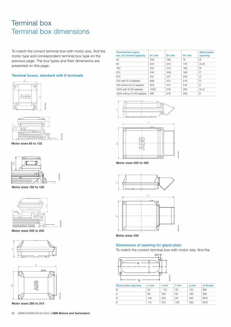
M00
0205
M00
0206
Motor sizes 80 to 132
Motor sizes 355 to 400
Motor sizes 280 to 315
Motor sizes 160 to 180
Terminal boxTerminal box dimensions
Motor sizes 200 to 250
M00
0365
M00
0369
M00
0368
M00
0368
Motor sizes 450
M00
0331
Terminal box types acc. to current capacity A1 mm B1 mm H1 mm
Gland plate opening
25 208 180 74 B
63 243 243 178 2x B
160 352 319 186 B
210 416 306 186 C
370 451 347 200 D
750 with E-D adapter 686 413 219 D
750 without E-D adapter 523 413 219 E
1200 with E-2D adapter 1000 578 285 2x D
1200 without E-2D adapter 697 578 285 E
To match the correct terminal box with motor size, find the motor type and correspondent terminal box type on the previous page. The box types and their dimensions are presented on this page.
Terminal boxes, standard with 6 terminals
Dimensions of opening for gland plateTo match the correct terminal box with motor size, find the
Gland plate opening c mm e mm f mm g mm d thread
B 32 115 30 120 M6
C 65 193 62 193 M8
D 100 300 80 292 M10
E 115 370 100 360 M12
M00
0088
92 9AKK104006 EN 02-2016 | ABB Motors and Generators

The pictures below show standard terminal boxes and the corresponding terminal boards for various motor sizes.
Fig 5. Terminal box for motor sizes 355 to 400, with adapter and cable sealing end unit.
Fig 4. Terminal box for motor sizes 280 to 315 with connection flange and cable glands.
M00
0423
M00
0424
Fig 1. Terminal box for motor sizes 80 to132
Fig 2. Terminal box for motor sizes 160 to 180
Fig 3. Terminal box for motor sizes 200 to 250
Fig 10. Terminal board for motor sizes 280 to 315.
Fig 11. Terminal board for motor sizes 355 to 400.
M00
0428
M00
0427
M00
0720
M00
0719
Fig 7. Terminal board for motor sizes 80 to 132
Fig 8. Terminal board for motor sizes 160 to 180
Fig 9. Terminal board for motor sizes 200 to 250
M00
0721
M
0007
18
M00
0723
M00
0722
Fig 12. Terminal board for motor size 450.
M00
0429
Fig 6. Terminal box for motor sizes 450, with adapter and cable sealing end unit.
M00
0425
Terminal boxTerminal boxes and boards
Cable glands are not delivered as standard.
Terminal boxes
Terminal boards
ABB Motors and Generators | 9AKK104006 EN 02-2016 93
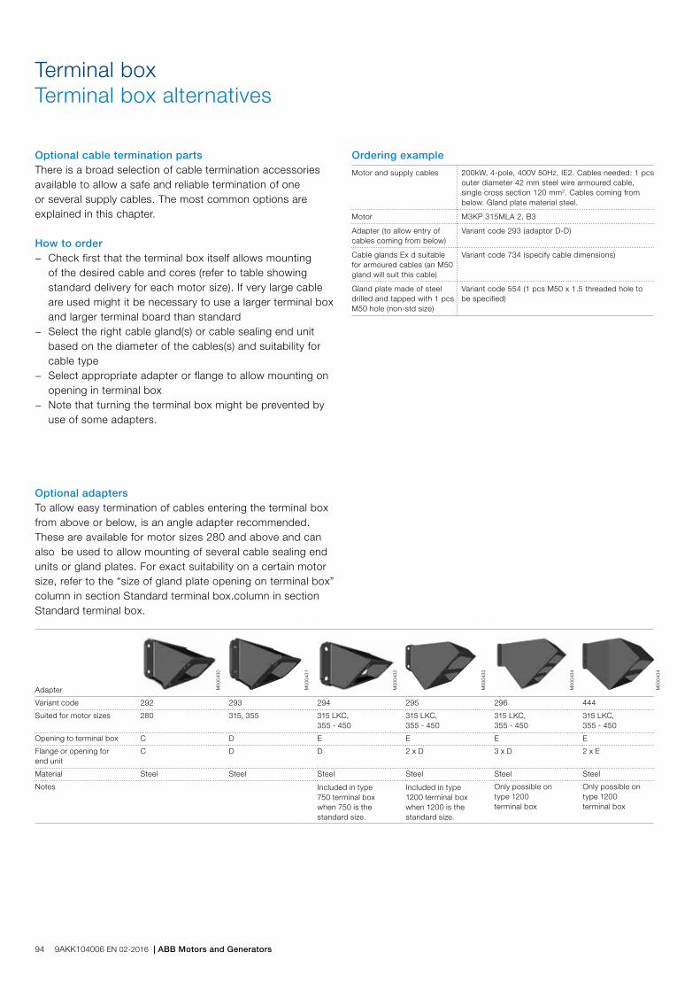
Optional cable termination partsThere is a broad selection of cable termination accessories available to allow a safe and reliable termination of one or several supply cables. The most common options are explained in this chapter.
How to order − Check first that the terminal box itself allows mounting
of the desired cable and cores (refer to table showing standard delivery for each motor size). If very large cable are used might it be necessary to use a larger terminal box and larger terminal board than standard
− Select the right cable gland(s) or cable sealing end unit based on the diameter of the cables(s) and suitability for cable type
− Select appropriate adapter or flange to allow mounting on opening in terminal box
− Note that turning the terminal box might be prevented by use of some adapters.
Terminal boxTerminal box alternatives
Adapter M00
0430
M00
0431
M00
0432
M00
0433
M00
0434
M00
0434
Variant code 292 293 294 295 296 444
Suited for motor sizes 280 315, 355 315 LKC,355 - 450
315 LKC,355 - 450
315 LKC,355 - 450
315 LKC,355 - 450
Opening to terminal box C D E E E E
Flange or opening for end unit
C D D 2 x D 3 x D 2 x E
Material Steel Steel Steel Steel Steel Steel
Notes Included in type 750 terminal box when 750 is the standard size.
Included in type 1200 terminal box when 1200 is the standard size.
Only possible on type 1200 terminal box
Only possible on type 1200 terminal box
Optional adaptersTo allow easy termination of cables entering the terminal box from above or below, is an angle adapter recommended. These are available for motor sizes 280 and above and can also be used to allow mounting of several cable sealing end units or gland plates. For exact suitability on a certain motor size, refer to the “size of gland plate opening on terminal box” column in section Standard terminal box.column in section Standard terminal box.
Ordering example
Motor and supply cables 200kW, 4-pole, 400V 50Hz, IE2. Cables needed: 1 pcs outer diameter 42 mm steel wire armoured cable, single cross section 120 mm2. Cables coming from below. Gland plate material steel.
Motor M3KP 315MLA 2, B3
Adapter (to allow entry of cables coming from below)
Variant code 293 (adaptor D-D)
Cable glands Ex d suitable for armoured cables (an M50 gland will suit this cable)
Variant code 734 (specify cable dimensions)
Gland plate made of steel drilled and tapped with 1 pcs M50 hole (non-std size)
Variant code 554 (1 pcs M50 x 1.5 threaded hole to be specified)
94 9AKK104006 EN 02-2016 | ABB Motors and Generators
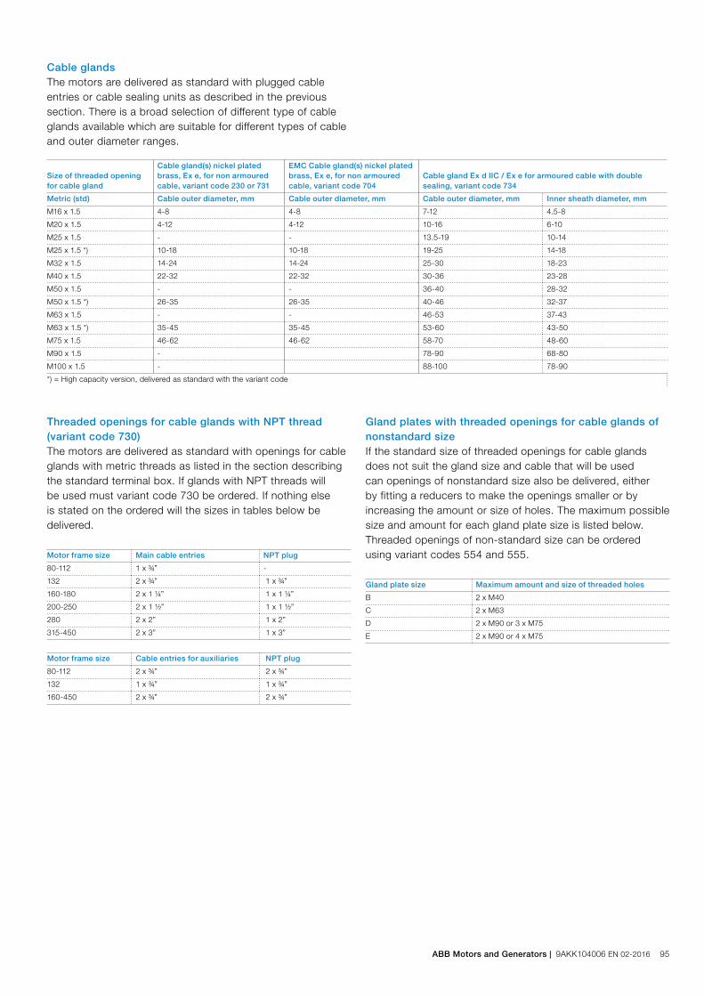
Gland plate size Maximum amount and size of threaded holes
B 2 x M40
C 2 x M63
D 2 x M90 or 3 x M75
E 2 x M90 or 4 x M75
Cable glandsThe motors are delivered as standard with plugged cable entries or cable sealing units as described in the previous section. There is a broad selection of different type of cable glands available which are suitable for different types of cable and outer diameter ranges.
Size of threaded opening for cable gland
Cable gland(s) nickel plated brass, Ex e, for non armoured cable, variant code 230 or 731
EMC Cable gland(s) nickel plated brass, Ex e, for non armoured cable, variant code 704
Cable gland Ex d IIC / Ex e for armoured cable with double sealing, variant code 734
Metric (std) Cable outer diameter, mm Cable outer diameter, mm Cable outer diameter, mm Inner sheath diameter, mm
M16 x 1.5 4-8 4-8 7-12 4.5-8
M20 x 1.5 4-12 4-12 10-16 6-10
M25 x 1.5 - - 13.5-19 10-14
M25 x 1.5 *) 10-18 10-18 19-25 14-18
M32 x 1.5 14-24 14-24 25-30 18-23
M40 x 1.5 22-32 22-32 30-36 23-28
M50 x 1.5 - - 36-40 28-32
M50 x 1.5 *) 26-35 26-35 40-46 32-37
M63 x 1.5 - - 46-53 37-43
M63 x 1.5 *) 35-45 35-45 53-60 43-50
M75 x 1.5 46-62 46-62 58-70 48-60
M90 x 1.5 - 78-90 68-80
M100 x 1.5 - 88-100 78-90
*) = High capacity version, delivered as standard with the variant code
Threaded openings for cable glands with NPT thread (variant code 730)The motors are delivered as standard with openings for cable glands with metric threads as listed in the section describing the standard terminal box. If glands with NPT threads will be used must variant code 730 be ordered. If nothing else is stated on the ordered will the sizes in tables below be delivered.
Motor frame size Main cable entries NPT plug
80-112 1 x ¾” -
132 2 x ¾” 1 x ¾”
160-180 2 x 1 ¼” 1 x 1 ¼”
200-250 2 x 1 ½” 1 x 1 ½”
280 2 x 2” 1 x 2”
315-450 2 x 3” 1 x 3”
Motor frame size Cable entries for auxiliaries NPT plug
80-112 2 x ¾” 2 x ¾”
132 1 x ¾” 1 x ¾”
160-450 2 x ¾” 2 x ¾”
Gland plates with threaded openings for cable glands of nonstandard sizeIf the standard size of threaded openings for cable glands does not suit the gland size and cable that will be used can openings of nonstandard size also be delivered, either by fitting a reducers to make the openings smaller or by increasing the amount or size of holes. The maximum possible size and amount for each gland plate size is listed below. Threaded openings of non-standard size can be ordered using variant codes 554 and 555.
ABB Motors and Generators | 9AKK104006 EN 02-2016 95

Gland plates of non-standard materialThe standard material used in gland plates is steel. Gland plates made of aluminum or stainless steel are optional, either with cable glands or blind without threaded holes. Please refer to the variant code section for more information.
Cable sealing end unitsAs an alternative to gland plates and cable glands, cable sealing end units can be used. These allow more space for spreading the cores for easy termination. Cable sealing units have rubber sealed entries for one or two main cables. In addition there are two plugged M20 holes for auxiliary cables. The cable sealing end units are Ex e certified, as option can they be equipped with EMC modules or cable clamping devices by adding variant codes 704 or 231.
End unit
M00
0436
M00
0437
M00
0438
Variant code 277 278 279
Suited for motor sizes 280 315, 355 315, 355
Opening to terminal box C D D
Cable outer diameter 1 - 2 cables, 48 - 60 mm 1 - 2 cables, 48 - 60 mm 1 - 2 cables, 60 - 80 mm
Cable entry for auxiliary cable 2 x M20 plugged holes
2 x M20 plugged holes
2 x M20 plugged holes
Additional optional variants EMC cable gland (704);Standard gland with clamping device (231)
EMC cable gland (704);Standard gland with clamping device (231)
EMC cable gland (704);Standard gland with clamping device (231)
96 9AKK104006 EN 02-2016 | ABB Motors and Generators
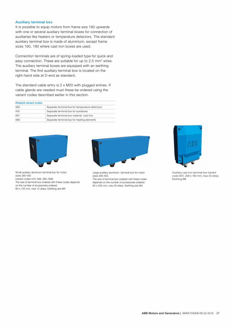
Auxiliary terminal boxIt is possible to equip motors from frame size 160 upwards with one or several auxiliary terminal boxes for connection of auxiliaries like heaters or temperature detectors. The standard auxiliary terminal box is made of aluminium, except frame sizes 160, 180 where cast iron boxes are used.
Connection terminals are of spring-loaded type for quick and easy connection. These are suitable for up to 2.5 mm2 wires. The auxiliary terminal boxes are equipped with an earthing terminal. The first auxiliary terminal box is located on the right-hand side at D-end as standard.
The standard cable entry is 2 x M20 with plugged entries. If cable glands are needed must these be ordered using the variant codes described earlier in this section.
Related variant codes
380 Separate terminal box for temperature detectors
418 Separate terminal box for auxiliaries
567 Separate terminal box material: cast Iron
568 Separate terminal box for heating elements
Small auxiliary aluminum terminal box for motor sizes 280-450 (variant codes 418, 568, 380, 569)The size of terminal box ordered with these codes depends on the number of accessories ordered.80 x 125 mm, max 12 strips. Earthing size M4
Large auxiliary aluminum terminal box for motor sizes 280-450.The size of terminal box ordered with these codes depends on the number of accessories ordered.80 x 250 mm, max 30 strips. Earthing size M4
Auxiliary cast iron terminal box (variant code 567). 208 x 180 mm, max 30 strips. Earthing M6
ABB Motors and Generators | 9AKK104006 EN 02-2016 97
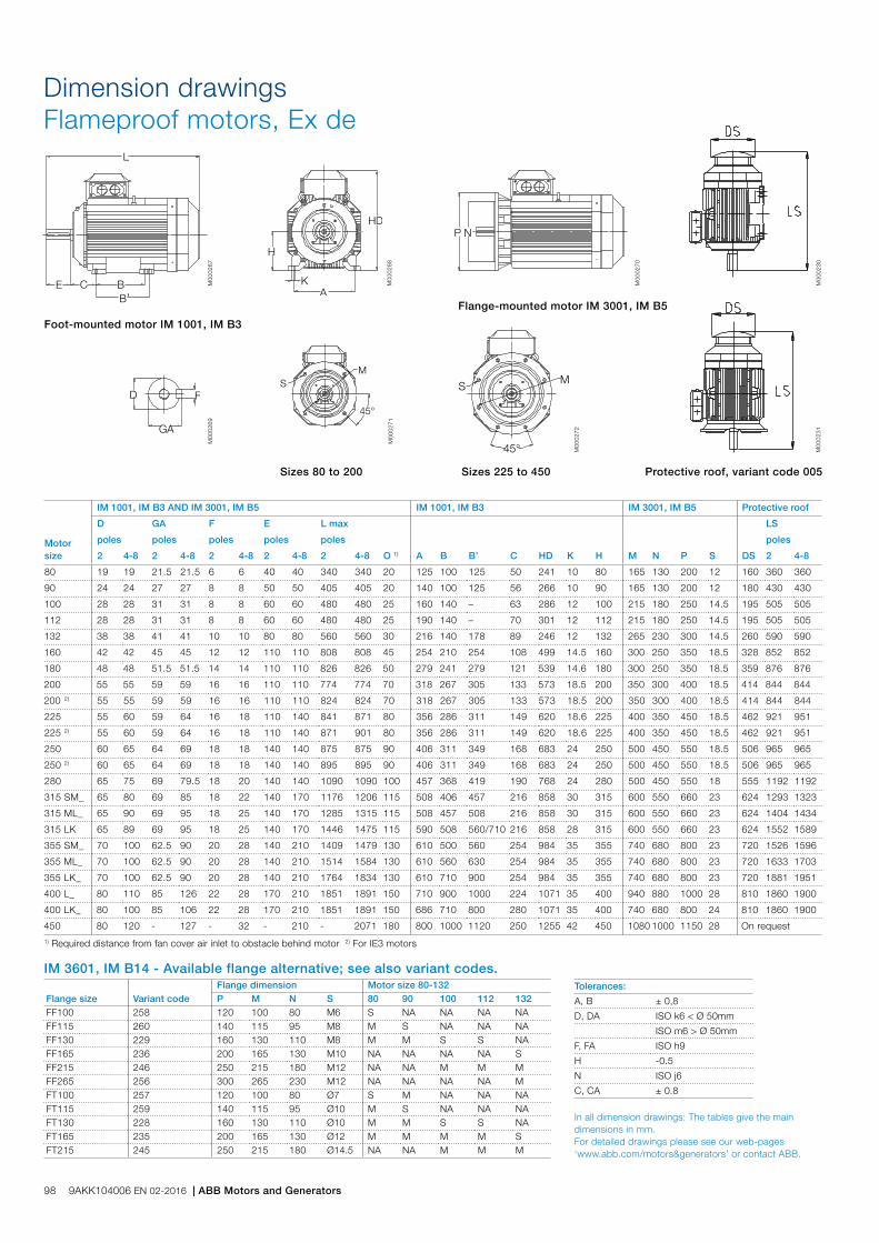
L
C BB’
E
H
KA
HD
GA
FD
P N
45°
SM
MS
45°
Dimension drawingsFlameproof motors, Ex de
Foot-mounted motor IM 1001, IM B3
Sizes 80 to 200 Protective roof, variant code 005
M00
0267
M00
0268
M00
0270
M00
0269
M00
0271
M00
0272
M00
0230
M00
0231
Motor size
IM 1001, IM B3 AND IM 3001, IM B5 IM 1001, IM B3 IM 3001, IM B5 Protective roof
D GA F E L max
O 1) A B B’ C HD K H M N P S DS
LS
poles poles poles poles poles poles
2 4-8 2 4-8 2 4-8 2 4-8 2 4-8 2 4-8
80 19 19 21.5 21.5 6 6 40 40 340 340 20 125 100 125 50 241 10 80 165 130 200 12 160 360 360
90 24 24 27 27 8 8 50 50 405 405 20 140 100 125 56 266 10 90 165 130 200 12 180 430 430
100 28 28 31 31 8 8 60 60 480 480 25 160 140 – 63 286 12 100 215 180 250 14.5 195 505 505
112 28 28 31 31 8 8 60 60 480 480 25 190 140 – 70 301 12 112 215 180 250 14.5 195 505 505
132 38 38 41 41 10 10 80 80 560 560 30 216 140 178 89 246 12 132 265 230 300 14.5 260 590 590
160 42 42 45 45 12 12 110 110 808 808 45 254 210 254 108 499 14.5 160 300 250 350 18.5 328 852 852
180 48 48 51.5 51.5 14 14 110 110 826 826 50 279 241 279 121 539 14.6 180 300 250 350 18.5 359 876 876
200 55 55 59 59 16 16 110 110 774 774 70 318 267 305 133 573 18.5 200 350 300 400 18.5 414 844 844
200 2) 55 55 59 59 16 16 110 110 824 824 70 318 267 305 133 573 18.5 200 350 300 400 18.5 414 844 844
225 55 60 59 64 16 18 110 140 841 871 80 356 286 311 149 620 18.6 225 400 350 450 18.5 462 921 951
225 2) 55 60 59 64 16 18 110 140 871 901 80 356 286 311 149 620 18.6 225 400 350 450 18.5 462 921 951
250 60 65 64 69 18 18 140 140 875 875 90 406 311 349 168 683 24 250 500 450 550 18.5 506 965 965
250 2) 60 65 64 69 18 18 140 140 895 895 90 406 311 349 168 683 24 250 500 450 550 18.5 506 965 965
280 65 75 69 79.5 18 20 140 140 1090 1090 100 457 368 419 190 768 24 280 500 450 550 18 555 1192 1192
315 SM_ 65 80 69 85 18 22 140 170 1176 1206 115 508 406 457 216 858 30 315 600 550 660 23 624 1293 1323
315 ML_ 65 90 69 95 18 25 140 170 1285 1315 115 508 457 508 216 858 30 315 600 550 660 23 624 1404 1434
315 LK 65 89 69 95 18 25 140 170 1446 1475 115 590 508 560/710 216 858 28 315 600 550 660 23 624 1552 1589
355 SM_ 70 100 62.5 90 20 28 140 210 1409 1479 130 610 500 560 254 984 35 355 740 680 800 23 720 1526 1596
355 ML_ 70 100 62.5 90 20 28 140 210 1514 1584 130 610 560 630 254 984 35 355 740 680 800 23 720 1633 1703
355 LK_ 70 100 62.5 90 20 28 140 210 1764 1834 130 610 710 900 254 984 35 355 740 680 800 23 720 1881 1951
400 L_ 80 110 85 126 22 28 170 210 1851 1891 150 710 900 1000 224 1071 35 400 940 880 1000 28 810 1860 1900
400 LK_ 80 100 85 106 22 28 170 210 1851 1891 150 686 710 800 280 1071 35 400 740 680 800 24 810 1860 1900
450 80 120 - 127 - 32 - 210 - 2071 180 800 1000 1120 250 1255 42 450 1080 1000 1150 28 On request
Flange-mounted motor IM 3001, IM B5
Sizes 225 to 450
Flange size Variant codeFlange dimension Motor size 80-132P M N S 80 90 100 112 132
FF100 258 120 100 80 M6 S NA NA NA NAFF115 260 140 115 95 M8 M S NA NA NAFF130 229 160 130 110 M8 M M S S NAFF165 236 200 165 130 M10 NA NA NA NA SFF215 246 250 215 180 M12 NA NA M M MFF265 256 300 265 230 M12 NA NA NA NA MFT100 257 120 100 80 Ø7 S M NA NA NAFT115 259 140 115 95 Ø10 M S NA NA NAFT130 228 160 130 110 Ø10 M M S S NAFT165 235 200 165 130 Ø12 M M M M SFT215 245 250 215 180 Ø14.5 NA NA M M M
IM 3601, IM B14 - Available flange alternative; see also variant codes.Tolerances:
A, B ± 0,8
D, DA ISO k6 < Ø 50mm
ISO m6 > Ø 50mm
F, FA ISO h9
H -0.5
N ISO j6
C, CA ± 0.8
In all dimension drawings: The tables give the main dimensions in mm. For detailed drawings please see our web-pages ‘www.abb.com/motors&generators’ or contact ABB.
1) Required distance from fan cover air inlet to obstacle behind motor 2) For IE3 motors
98 9AKK104006 EN 02-2016 | ABB Motors and Generators

Certificate examples
M00
0725
-2
M00
0725
-1M
0007
26a
M00
0727
a
ABB Motors and Generators | 9AKK104006 EN 02-2016 99

Motor size 80 90 100 112 132 160 180
Stator Material Cast iron, EN-GJL-200 or better
Paint colour shade Blue, Munsell 8B 4.5/3.25
Corrosion class C3 medium according to ISO/EN 12944-5
Feet Forged steel, detachable feet
Bearing end shields Material Cast iron, EN-GJL-200 or better
Paint colour shade Blue, Munsell 8B 4.5/3.25
Corrosion class C3 medium according to ISO/EN 12944-5
Bearings D-end 2-12 pole 6205-2Z/C3 6205-2Z/C3 6206-2Z/C3 6206-2Z/C3 6208-2Z/C3 6309/C3 6310/C3
N-end 2-12 pole 6204-2Z/C3 6205-2Z/C3 6206-2Z/C3 6206-2Z/C3 6208-2Z/C3 6309/C3 6310/C3
Axially-locked bearings Inner bearing cover As standard, locked at D-end
Bearing seal Gamma-ring
Lubrication Permanent grease lubrication Regreasable bearings
SPM-nipples - As standard
Rating plate Material Stainless steel
Terminal box Frame material Cast iron, EN-GJL-200 or better
Cover material Cast iron, EN-GJL-200 or better
Cover screws material Acidproof steel A4-80 Steel 8.8, zinc electroplated and chromated.
Connections Cable entries 1 x M25 + 1 x M20 plugged 2 x M32 + 1 x M20 plugged 2 x M40 + 2 x M20 plugged
Terminals 6 terminals for connection with cable lugs (not included)
Fan Material Polyamide. Reinforced with glass fibre. Polypropylene. Reinforced with glass fibre.
Fan cover Material Steel Hot dip galvanized steel
Paint colour shade Blue, Munsell 8B 4.5/3.25
Corrosion class C3 medium according to ISO/EN 12944-5
Stator winding Material Copper
Insulation Insulation class F
Winding protection 3 pcs thermistors as standard
Rotor winding Material Pressure die-cast aluminum
Balancing Half key balancing
Key way Closed key-way
Drain holes - Optional
External earthing bolt As standard
Enclosure IP 55
Cooling method IC 411
Motors in briefFlameproof motors Ex de, sizes 80 to 180
100 9AKK104006 EN 02-2016 | ABB Motors and Generators

Motor size 200 225 250 280 315 355 400 450
Stator Material Cast iron, EN-GJL-200 or better
Paint colour shade Blue, Munsell 8B 4.5/3.25
Corrosion class C3 medium according to ISO/EN 12944-5
Feet Cast iron, EN-GJL-200 or better, integrated with stator
Bearing end shields Material Cast iron, EN-GJL-200 or better
Paint colour shade Blue, Munsell 8B 4.5/3.25
Corrosion class C3 medium according to ISO/EN 12944-5
Bearings D-end 2-pole 6312M/C3 6313M/C3 6315M/C3 6316/C3 6316/C3 6316M/C3 6317M/C3 -
4-12 -pole 6312/C3 6313/C3 6315/C3 6316/C3 6319/C3 6322/C3 6324/C3 6326M/C3
N-end 2-pole 6310M/C3 6312M/C3 6313M/C3 6316/C3 6316/C3 6316M/C3 6317M/C3 -
4-12 -pole 6310/C3 6312/C3 6313/C3 6316/C3 6316/C3 6316/C3 6319/C3 6322/C3
Axially-locked bearings Inner bearing cover As standard, locked at D-end
Bearing seal Gamma-ring Labyrinth seal
Lubrication Regreasable bearings
SPM-nipples As standard
Rating plate Material Stainless steel
Terminal box Frame material Cast iron, EN-GJL-200 or better
Cover material Cast iron, EN-GJL-200 or better Steel
Cover screws material Steel 8.8, zinc electroplated and chromated
Connections Cable entries 2 x M50 + 2 x M20 plugged 2 x M63 + 2 x M20 plugged Refer to table on page 91
Terminals 6 terminals for connection with cable lugs (not included)
Fan Material Polypropylene. Reinforced with glass fibre. Polypropylene reinforced with glass fibre or aluminum.
Fan cover Material Hot dip galvanized steel
Paint colour shade Blue, Munsell 8B 4.5/3.25
Corrosion class C3 medium according to ISO/EN 12944-5
Stator winding Material Copper
Insulation Insulation class F
Winding protection 3 pcs thermistors as standard
Rotor winding Material Pressure die-cast aluminum
Balancing Half key balancing
Key way Close Open
Heating elements On request 25 W 60 W 120 W 200W
Drain holes Optional
External earthing bolt As standard
Enclosure IP 55
Cooling method IC 411
Motors in briefFlameproof motors Ex de, sizes 200 to 450
ABB Motors and Generators | 9AKK104006 EN 02-2016 101
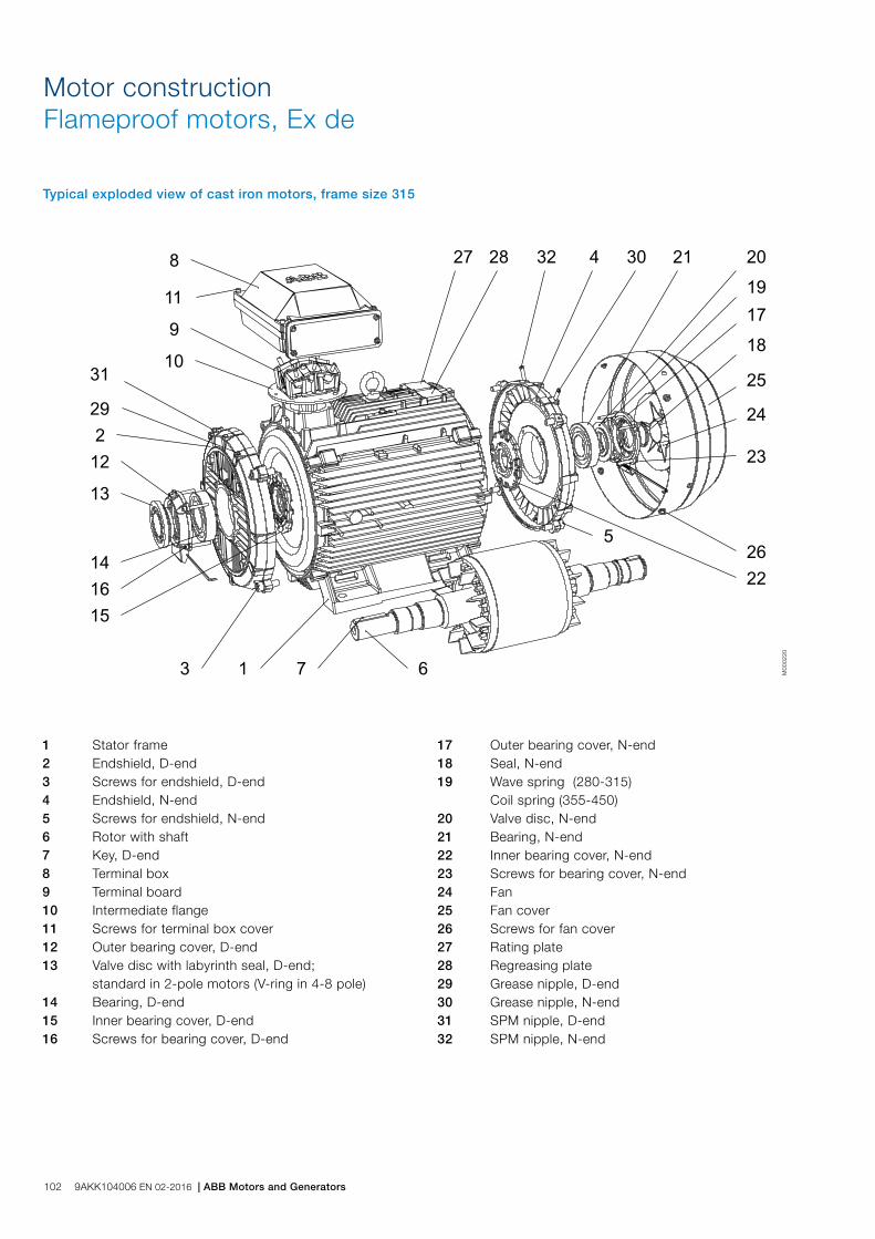
Motor constructionFlameproof motors, Ex de
Typical exploded view of cast iron motors, frame size 315
1 Stator frame 2 Endshield, D-end 3 Screws for endshield, D-end 4 Endshield, N-end 5 Screws for endshield, N-end 6 Rotor with shaft 7 Key, D-end 8 Terminal box 9 Terminal board 10 Intermediate flange 11 Screws for terminal box cover 12 Outer bearing cover, D-end 13 Valve disc with labyrinth seal, D-end; standard in 2-pole motors (V-ring in 4-8 pole) 14 Bearing, D-end 15 Inner bearing cover, D-end 16 Screws for bearing cover, D-end
17 Outer bearing cover, N-end 18 Seal, N-end 19 Wave spring (280-315) Coil spring (355-450) 20 Valve disc, N-end 21 Bearing, N-end 22 Inner bearing cover, N-end 23 Screws for bearing cover, N-end 24 Fan 25 Fan cover 26 Screws for fan cover 27 Rating plate 28 Regreasing plate 29 Grease nipple, D-end 30 Grease nipple, N-end 31 SPM nipple, D-end 32 SPM nipple, N-end
M00
0220
102 9AKK104006 EN 02-2016 | ABB Motors and Generators

Increased safety motors, Ex e IIC T3 GbTotally enclosed squirrel cage three phase low voltage motors, Sizes 80 to 400, 0.55 to 390 kW
Ordering information 104
Rating plates 105
Technical data IE2 106
3000 r/min motors 106
1500 r/min motors 107
1000 r/min motors 108
750 r/min motors 109
Technical data IE2 110
3000, 1500 and 1000 r/min motors 110
750 r/min motors 111
Variant codes 112
Mechanical design 116
Motor frame and drain holes 116
Heating elements 117
Bearings 119
Terminal box 125
Dimension drawings 132
Certificate examples 133
Increased safety motors Ex e in brief 134
Motor construction 136
ABB Motors and Generators | 9AKK104006 EN 02-2016 103

When placing an order, specify motor type, size and product code according to the following example.
Positions 1 - 4
3GHP: Totally enclosed fan cooled squirrel cage motor with cast iron frame, increased safety
Positions 5 and 6
IEC-frame
08: 80
09: 90
10: 100
11: 112
13: 132
16: 160
18: 180
20: 200
22: 225
25: 250
28: 280
31: 315
35: 355
40: 400
Position 7
Speed (Pole pairs)
1: 2 poles
2: 4 poles
3: 6 poles
4: 8 poles
Positions 8 to 10
Serial number
Position 11
- (Dash)
Position 12
Mounting arrangement
A: Foot-mounted, top-mounted terminal box
R: Foot-mounted, terminal box RHS seen from D-end
L: Foot-mounted, terminal box LHS seen from D-end
B: Flange-mounted, large flange
C: Flange-mounted, small flange (size 90 to 132)
H: Foot- and flange-mounted, terminal box top-mounted
J: Foot- and flange-mounted, small flange with tapped holes
S: Foot- and flange-mounted, terminal box RHS seen from D-end
T: Foot- and flange-mounted, terminal box LHS seen from D-end
Ordering information
V Flange-mounted, special flange
F: Foot- and flange-mounted. Special flange
Position 13
Voltage and frequency
Single-speed motors
B: 380 VΔ 50 Hz
D: 400 VΔ, 415 VΔ, 690 VY 50 Hz
E: 500 VΔ 50 Hz
F: 500 VY 50 Hz
S: 230 VΔ, 400 VY, 415 VY 50 Hz
T: 660 VΔ 50 Hz
U: 690 VΔ 50 Hz
X: Other rated voltage, connection or frequency, 690 V maximum
Position 14
Generation code
G, H... The product code must be, if needed, followed by variant codes.
Explanation of the product codeMotor type Motor size Product code Mounting arrangement code,
Voltage and frequency code,Generation code
Variant codes
M3HP 160MLB 3GHP 161 420 - ADH 002, etc. 1 2 3 4 5 6 7 8 9 10 11 12 13 14
Example
Motor type M3HP 160 MLB
Pole number 2
Mounting arrangement (IM-code) IM B3 (IM 1001)
Rated output 8 kW
Product code 3GHP161420-ADH
Variant codes if needed
104 9AKK104006 EN 02-2016 | ABB Motors and Generators

Plates
Rating plates
Motor sizes 80 to 400
M00
0738
The rating plates are in table form giving values for speed, current and power factor for one voltage: 400 V as standard. Other voltage and frequency combinations are possible and can be ordered with variant codes 002 or 209. Please see Variant code section.
The following information will be shown on the motor rating plate:
− Lowest nominal efficiency at 100 %, 75 % and 50 % rated load
− Efficiency level − Year of manufacture − Type of protection − Apparatus group − Temperature class − Identification number of the certification body − Certificate number: ATEX − IA/IN − tE
ABB Motors and Generators | 9AKK104006 EN 02-2016 105
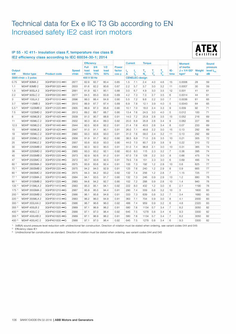
IP 55 - IC 411- Insulation class F, temperature rise class B IE2 efficiency class according to IEC 60034-30-1; 2014
Technical data for Ex e IIC T3 Gb according to EN Increased safety IE2 cast iron motors
Output kW Motor type Product code
Speed r/min
Efficiency
Power factor cos j
Current Torque
tE-time
Moment of inertiaJ = 1/4 GD2 kgm2
Weight kg
Sound pressure level LPA dB
Full load 100%
3/4load 75%
1/2 load 50%
IN A
Is IN
TN Nm
Tl TN
Tb TN
3000 r/min = 2 poles 400 V 50 Hz CENELEC-design
0.75 M3HP 80MA 2 3GHP081310-••H 2877 82.9 82.7 80.4 0.85 1.5 7.1 2.4 4.0 4.6 15 0.0006 28 59
1.1 M3HP 80MB 2 3GHP081320-••H 2833 81.6 82.2 80.6 0.87 2.2 5.7 3.7 3.0 3.2 11 0.0007 30 59
1.5 M3HP 90SLA 2 3GHP091010-••H 2881 81.9 82.1 80.1 0.88 3.0 6.7 4.9 3.0 3.5 12 0.001 41 61
2.2 M3HP 90SLC 2 3GHP091030-••H 2877 84.5 85.0 83.8 0.89 4.2 7.3 7.3 2.7 3.5 6 0.0014 44 61
3 M3HP 100LA 2 3GHP101510-••H 2896 86.0 86.4 84.8 0.90 5.5 7.2 9.8 2.2 3.0 7 0.0036 61 65
3.7 M3HP 112MB 2 3GHP111320-••H 2910 86.9 87.7 87.4 0.89 6.9 7.8 12.1 3.9 4.0 5 0.0043 64 65
5.5 2) M3HP 132SMB 2 3GHP131220-••H 2905 86.9 87.3 85.8 0.90 10.1 7.0 18.0 2.4 3.3 9 0.009 92 71
7.5 M3HP 132SMD 2 3GHP131240-••H 2913 89.2 89.7 88.7 0.90 13.4 7.6 24.5 3.0 4.0 5 0.012 100 71
8 M3HP 160MLB 2 3GHP161420-••H 2939 91.0 90.7 88.8 0.91 14.0 7.2 25.9 2.8 3.5 15 0.052 216 69
11 M3HP 160MLC 2 3GHP161430-••H 2932 90.3 90.4 89.3 0.92 20.0 6.9 35.8 2.6 3.4 9 0.062 227 69
12.5 M3HP 160MLD 2 3GHP161440-••H 2944 92.5 92.6 92.2 0.91 21.4 7.6 40.5 2.8 3.4 8 0.07 233 69
15 M3HP 180MLB 2 3GHP181420-••H 2947 91.0 91.1 90.1 0.91 26.0 7.1 48.6 2.2 3.0 15 0.13 292 69
18 M3HP 180MLC 2 3GHP181430-••H 2960 93.3 93.6 93.0 0.91 31.0 7.6 58.0 2.4 3.2 11 0.13 292 69
22 M3HP 200MLC 2 3GHP201430-••G 2956 91.9 91.7 90.2 0.90 38.5 6.9 71.0 2.6 3.5 10 0.21 305 72
25 M3HP 200MLE 2 3GHP201450-••G 2957 93.8 93.9 93.0 0.90 44.0 7.0 80.7 2.9 3.8 9 0.22 310 72
30 M3HP 225SMB 2 3GHP221220-••G 2963 92.3 92.0 90.5 0.91 51.0 7.4 96.6 2.1 3.0 10 0.31 365 74
36 M3HP 225SMD 2 3GHP221240-••G 2965 93.3 93.2 92.1 0.92 60.0 8.0 115 2.3 3.2 7 0.36 395 74
40 M3HP 250SMB 2 3GHP251220-••G 2973 92.9 92.6 91.2 0.91 67.0 7.8 128 2.2 3.0 8 0.66 475 74
47 M3HP 250SMC 2 3GHP251230-••G 2972 93.7 93.6 92.5 0.91 79.5 7.8 151 2.3 3.0 6 0.69 495 74
60 1) M3HP 280SMA 2 3GHP281210-••G 2975 93.9 93.6 92.4 0.91 100 7.3 192 1.2 2.9 10 0.8 625 77
75 1) M3HP 280SMB 2 3GHP281220-••G 2975 94.2 94.0 92.9 0.91 125 7.6 240 1.2 2.9 8 0.9 665 77
80 1) M3HP 280SMC 2 3GHP281230-••G 2975 94.3 94.2 93.2 0.92 132 7.4 256 1.2 2.8 7 1.15 725 77
77 1) M3HP 315SMA 2 3GHP311210-••G 2984 94.1 93.5 91.7 0.90 132 7.3 246 0.9 2.9 13 1.2 880 78
90 1) M3HP 315SMB 2 3GHP311220-••G 2983 94.6 94.2 92.7 0.90 152 7.2 288 0.9 2.8 10 1.4 940 78
135 1) M3HP 315MLA 2 3GHP311410-••G 2983 95.3 95.1 94.1 0.92 222 8.0 432 1.2 3.0 6 2.1 1190 78
175 1) M3HP 355SMA 2 3GHP351210-••G 2987 95.9 95.5 94.4 0.91 290 7.4 559 0.8 3.2 10 3 1600 83
200 1) M3HP 355SMB 2 3GHP351220-••G 2986 96.1 95.8 94.8 0.91 333 7.3 639 0.8 3.2 7 3.4 1680 83
220 1) M3HP 355MLA 2 3GHP351410-••G 2983 96.2 96.0 94.9 0.91 363 7.1 704 0.9 3.0 8 4.1 2000 83
300 1) M3HP 355LKA 2 3GHP351810-••G 2986 96.7 96.6 96.0 0.92 488 7.4 959 0.9 3.2 6 4.8 2320 83
355 3) M3HP 400LB 2 3GHP401520-••G 2989 97.1 96.9 96.2 0.91 580 7.6 1134 0.7 3.4 7 8.2 3050 82
400 3) M3HP 400LC 2 3GHP401530-••G 2988 97.1 97.0 96.4 0.92 645 7.5 1278 0.8 3.4 6 9.3 3300 82
355 3) M3HP 400LKB 2 3GHP401820-••G 2989 97.1 96.9 96.2 0.91 580 7.6 1134 0.7 3.4 7 8.2 3050 82
400 3) M3HP 400LKC 2 3GHP401830-••G 2988 97.1 97.0 96.4 0.92 645 7.5 1278 0.8 3.4 6 9.3 3300 82
1) 3dB(A) sound pressure level reduction with unidirectional fan construction. Direction of rotation must be stated when ordering. see variant codes 044 and 0452) Efficiency class IE13) Unidirectional fan construction as standard. Direction of rotation must be stated when ordering. see variant codes 044 and 045
106 9AKK104006 EN 02-2016 | ABB Motors and Generators
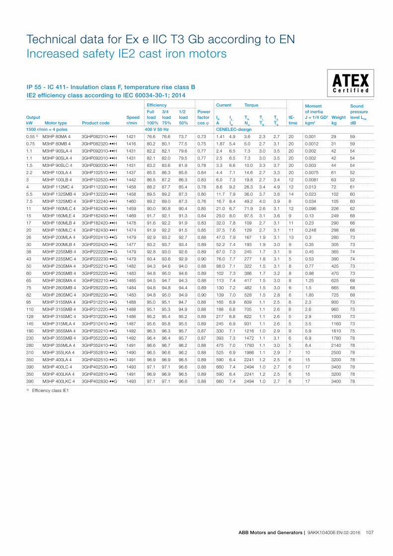
IP 55 - IC 411- Insulation class F, temperature rise class B IE2 efficiency class according to IEC 60034-30-1; 2014
Technical data for Ex e IIC T3 Gb according to ENIncreased safety IE2 cast iron motors
Output kW Motor type Product code
Speed r/min
Efficiency
Power factor cos j
Current Torque
tE-time
Moment of inertiaJ = 1/4 GD2 kgm2
Weight kg
Sound pressure level LPA dB
Full load 100%
3/4load 75%
1/2 load 50%
IN A
Is IN
TN Nm
Tl TN
Tb TN
1500 r/min = 4 poles 400 V 50 Hz CENELEC-design
0.55 2) M3HP 80MA 4 3GHP082310-••H 1421 76.6 76.6 73.7 0.73 1.41 4.9 3.6 2.3 2.7 20 0.001 29 59
0.75 M3HP 80MB 4 3GHP082320-••H 1416 80.2 80.1 77.5 0.75 1.87 5.4 5.0 2.7 3.1 20 0.0012 31 59
1.1 M3HP 90SLA 4 3GHP092010-••H 1431 82.2 82.1 79.6 0.77 2.4 6.5 7.3 3.0 3.5 20 0.002 42 54
1.1 M3HP 90SLA 4 3GHP092010-••H 1431 82.1 82.0 79.5 0.77 2.5 6.5 7.3 3.0 3.5 20 0.002 42 54
1.5 M3HP 90SLC 4 3GHP092030-••H 1431 83.2 83.6 81.9 0.78 3.3 6.6 10.0 3.3 3.7 20 0.003 44 54
2.2 M3HP 100LA 4 3GHP102510-••H 1437 85.5 86.3 85.6 0.84 4.4 7.1 14.6 2.7 3.3 20 0.0075 61 52
3 M3HP 100LB 4 3GHP102520-••H 1442 86.5 87.2 86.3 0.83 6.0 7.3 19.8 2.7 3.4 12 0.0081 63 52
4 M3HP 112MC 4 3GHP112330-••H 1458 88.2 87.7 85.4 0.78 8.6 9.2 26.3 3.4 4.9 12 0.013 72 61
5.5 M3HP 132SMB 4 3GHP132220-••H 1458 89.5 89.2 87.3 0.80 11.7 7.9 36.0 3.7 3.8 14 0.023 102 60
7.5 M3HP 132SMD 4 3GHP132240-••H 1460 89.2 89.0 87.3 0.76 16.7 8.4 49.2 4.0 3.9 8 0.034 105 60
11 M3HP 160MLC 4 3GHP162430-••H 1459 90.0 90.8 90.4 0.85 21.0 6.7 71.9 2.6 3.1 12 0.096 226 62
15 M3HP 160MLE 4 3GHP162450-••H 1469 91.7 92.1 91.3 0.84 29.0 8.0 97.5 3.1 3.6 9 0.13 249 68
17 M3HP 180MLB 4 3GHP182420-••H 1478 91.6 92.2 91.9 0.83 32.0 7.8 109 2.7 3.1 11 0.23 290 66
20 M3HP 180MLC 4 3GHP182430-••H 1474 91.9 92.2 91.5 0.85 37.5 7.6 129 2.7 3.1 11 0.248 298 66
26 M3HP 200MLA 4 3GHP202410-••G 1479 92.9 93.2 92.7 0.88 47.0 7.9 167 1.9 3.1 13 0.3 280 73
30 M3HP 200MLB 4 3GHP202420-••G 1477 93.2 93.7 93.4 0.89 52.2 7.4 193 1.9 3.0 9 0.35 305 73
38 M3HP 225SMB 4 3GHP222220••-G 1479 92.8 93.0 92.6 0.89 67.0 7.3 245 1.7 3.1 9 0.45 365 74
43 M3HP 225SMC 4 3GHP222230-••G 1479 93.4 93.6 92.9 0.90 76.0 7.7 277 1.8 3.1 5 0.53 390 74
50 M3HP 250SMA 4 3GHP252210-••G 1482 94.3 94.6 94.0 0.88 88.0 7.1 322 1.5 3.1 8 0.77 425 73
60 M3HP 250SMB 4 3GHP252220-••G 1483 94.8 95.0 94.6 0.89 102 7.3 386 1.7 3.2 8 0.98 470 73
65 M3HP 280SMA 4 3GHP282210-••G 1485 94.5 94.7 94.3 0.88 113 7.4 417 1.5 3.0 8 1.25 625 68
75 M3HP 280SMB 4 3GHP282220-••G 1484 94.6 94.8 94.4 0.89 130 7.2 482 1.5 3.0 6 1.5 665 68
82 M3HP 280SMC 4 3GHP282230-••G 1483 94.8 95.0 94.9 0.90 139 7.0 528 1.5 2.8 6 1.85 725 68
95 M3HP 315SMA 4 3GHP312210-••G 1488 95.0 95.1 94.7 0.88 165 6.9 609 1.1 2.5 8 2.3 900 73
110 M3HP 315SMB 4 3GHP312220-••G 1488 95.1 95.3 94.9 0.88 188 6.8 705 1.1 2.6 8 2.6 960 73
128 M3HP 315SMC 4 3GHP312230-••G 1486 95.2 95.4 95.2 0.89 217 6.8 822 1.1 2.6 5 2.9 1000 73
145 M3HP 315MLA 4 3GHP312410-••G 1487 95.6 95.8 95.5 0.89 245 6.9 931 1.1 2.6 5 3.5 1160 73
190 M3HP 355SMA 4 3GHP352210-••G 1492 96.3 96.3 95.7 0.87 330 7.1 1216 1.0 2.9 9 5.9 1610 75
230 M3HP 355SMB 4 3GHP352220-••G 1492 96.4 96.4 95.7 0.87 393 7.3 1472 1.1 3.1 6 6.9 1780 78
280 M3HP 355MLA 4 3GHP352410-••G 1491 96.6 96.7 96.2 0.88 475 7.0 1793 1.1 3.0 5 8.4 2140 78
310 M3HP 355LKA 4 3GHP352810-••G 1490 96.5 96.6 96.2 0.88 525 6.9 1986 1.1 2.9 7 10 2500 78
350 M3HP 400LA 4 3GHP402510-••G 1491 96.9 96.9 96.5 0.89 590 6.4 2241 1.2 2.5 6 15 3200 78
390 M3HP 400LC 4 3GHP402530-••G 1493 97.1 97.1 96.6 0.88 660 7.4 2494 1.0 2.7 6 17 3400 78
350 M3HP 400LKA 4 3GHP402810-••G 1491 96.9 96.9 96.5 0.89 590 6.4 2241 1.2 2.5 6 15 3200 78
390 M3HP 400LKC 4 3GHP402830-••G 1493 97.1 97.1 96.6 0.88 660 7.4 2494 1.0 2.7 6 17 3400 78
2) Efficiency class IE1
ABB Motors and Generators | 9AKK104006 EN 02-2016 107

IP 55 - IC 411- Insulation class F, temperature rise class B IE2 efficiency class according to IEC 60034-30-1; 2014
Technical data for Ex e IIC T3 Gb according to EN Increased safety IE2 cast iron motors
Output kW Motor type Product code
Speed r/min
Efficiency
Power factor cos j
Current Torque
tE-time
Moment of inertiaJ = 1/4 GD2 kgm2
Weight kg
Sound pressure level LPA dB
Full load 100%
3/4load 75%
1/2 load 50%
IN A
Is IN
TN Nm
Tl TN
Tb TN
1000 r/min = 6 poles 400 V 50 Hz CENELEC-design
0.37 M3HP 80MA 6 3GHP083310-••H 952 71.6 68.4 61.4 0.58 1.28 4.6 3.7 3.5 3.9 20 0.0022 29 50
0.55 2) M3HP 80MB 6 3GHP083320-••H 938 70.3 68.1 61.8 0.65 1.73 4.2 5.5 2.7 3.1 20 0.0022 29 50
0.75 M3HP 90SLA 6 3GHP093010-••H 946 79.2 78.2 74.1 0.64 2.1 5.5 7.6 3.1 3.6 20 0.0037 41 44
1.5 M3HP 100LA 6 3GHP103510-••H 954 81.6 81.4 78.8 0.72 3.6 5.8 15.0 2.5 3.0 20 0.012 60 54
2.2 M3HP 112MB 6 3GHP113320-••H 951 82.5 82.2 79.4 0.73 5.3 6.2 22.0 2.5 3.1 18 0.014 63 54
3 M3HP 132SMB 6 3GHP133220-••H 966 84.0 84.3 82.5 0.76 6.7 6.2 29.6 2.0 3.0 20 0.032 96 57
4 M3HP 132SMC 6 3GHP133230-••H 966 85.7 85.9 84.6 0.75 8.9 6.8 39.5 2.3 3.4 17 0.034 98 57
5.5 M3HP 132SMD 6 3GHP133240-••H 967 87.5 87.7 86.2 0.72 12.7 7.2 54.3 2.3 3.6 15 0.039 105 62
6.6 M3HP 160MLA 6 3GHP163410-••H 977 88.0 89.0 88.8 0.76 13.8 7.6 64.5 2.1 3.3 14 0.126 247 65
7.5 M3HP 160MLB 6 3GHP163420-••H 971 88.2 88.6 87.7 0.78 16.0 7.5 73.7 2.4 3.6 18 0.126 247 65
11 2) M3HP 160MLC 6 3GHP163430-••H 971 88.4 88.9 88.1 0.77 24.0 7.8 108 2.6 3.8 7 0.126 247 65
14 2) M3HP 180MLB 6 3GHP183420-••H 975 87.9 89.5 90.0 0.84 29.0 7.2 137 1.8 3.0 9 0.25 298 67
16.5 M3HP 200MLB 6 3GHP203420-••G 984 91.8 92.0 91.1 0.85 31.0 7.0 160 3.2 3.3 23 0.47 290 65
20 M3HP 200MLC 6 3GHP203430-••G 983 92.4 92.9 92.3 0.85 38.0 7.1 194 3.0 2.7 17 0.52 305 65
30 M3HP 225SMC 6 3GHP223230-••G 985 92.9 93.1 92.7 0.84 56.5 7.0 290 2.9 3.0 7 0.78 380 64
37 M3HP 250SMB 6 3GHP253220-••G 988 93.0 93.4 92.9 0.87 66.5 7.2 357 2.6 2.8 10 1.6 465 65
45 M3HP 280SMA 6 3GHP283210-••G 986 93.1 93.5 93.3 0.88 79.0 6.7 435 1.5 2.8 13 1.85 605 66
50 M3HP 280SMB 6 3GHP283220-••G 987 93.6 94.0 93.8 0.88 87.0 7.3 483 1.4 2.6 9 2.2 645 66
62 M3HP 280SMC 6 3GHP283230-••G 986 93.8 94.3 94.2 0.88 106 7.6 600 1.5 2.6 6 2.85 725 66
72 M3HP 315SMA 6 3GHP313210-••G 992 93.8 93.9 93.1 0.84 130 7.2 693 1.3 2.5 7 3.2 830 72
85 M3HP 315SMB 6 3GHP313220-••G 991 94.0 94.3 93.8 0.87 148 7.3 819 1.3 2.4 6 4.1 930 72
100 M3HP 315SMC 6 3GHP313230-••G 991 94.3 94.7 94.5 0.86 177 6.7 963 1.2 2.2 14 4.9 1000 72
120 M3HP 315MLA 6 3GHP313410-••G 991 94.8 94.9 94.6 0.86 212 7.6 1156 1.3 2.5 5 5.8 1150 72
150 M3HP 355SMA 6 3GHP353210-••G 993 95.5 95.5 94.9 0.84 265 6.8 1442 1.3 2.6 6 7.9 1510 75
180 M3HP 355SMB 6 3GHP353220-••G 994 95.7 95.7 95.0 0.86 315 7.2 1729 1.3 2.6 5 9.7 1680 75
260 M3HP 355LKA 6 3GHP353810-••G 993 96.0 96.1 95.5 0.85 458 7.1 2500 1.4 2.6 6 15.5 2500 75
300 M3HP 400LA 6 3GHP403510-••G 995 96.5 96.5 96.0 0.84 532 6.9 2879 1.3 2.5 6 17 2900 76
350 M3HP 400LB 6 3GHP403520-••G 995 96.7 96.7 96.2 0.84 620 7.4 3359 1.4 2.6 6 20.5 3150 76
300 M3HP 400LKA 6 3GHP403810-••G 995 96.5 96.5 96.0 0.84 532 6.9 2879 1.3 2.5 6 17 2900 76
350 M3HP 400LKB 6 3GHP403820-••G 995 96.7 96.7 96.2 0.84 620 7.4 3359 1.4 2.6 6 20.5 3150 76
2) Efficiency class IE1
108 9AKK104006 EN 02-2016 | ABB Motors and Generators
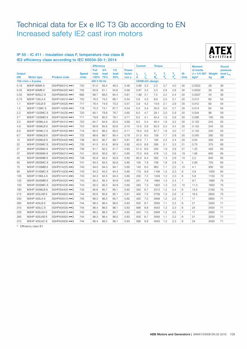
IP 55 - IC 411 - Insulation class F, temperature rise class B IE2 efficiency class according to IEC 60034-30-1; 2014
Technical data for Ex e IIC T3 Gb according to EN Increased safety IE2 cast iron motors
Output kW Motor type Product code
Speed r/min
Efficiency
Power factor cos j
Current Torque
tE-time
Moment of inertiaJ = 1/4 GD2 kgm2
Weight kg
Sound pressure level LPA dB
Full load 100%
3/4load 75%
1/2 load 50%
IN A
Is IN
TN Nm
Tl TN
Tb TN
750 r/min = 8 poles 400 V 50 Hz CENELEC-design
0.18 M3HP 80MA 8 3GHP084310-••H 720 61.0 56.4 48.3 0.48 0.88 3.3 2.3 3.7 4.0 30 0.0022 29 36
0.25 M3HP 80MB 8 3GHP084320-••H 705 63.8 61.1 54.6 0.58 0.97 3.2 3.3 2.6 2.8 30 0.0022 29 36
0.55 M3HP 90SLC 8 3GHP094030-••H 695 68.7 68.5 64.4 0.61 1.89 3.1 7.5 2.2 2.4 20 0.0037 43 36
0.75 M3HP 100LA 8 3GHP104510-••H 720 76.5 74.2 68.1 0.54 2.6 4.3 9.9 2.5 3.1 20 0.012 60 54
1.1 M3HP 100LB 8 3GHP104520-••H 717 76.4 74.9 70.2 0.57 3.9 4.2 14.6 2.1 2.9 20 0.012 60 54
1.5 M3HP 112MC 8 3GHP114330-••H 716 75.3 73.1 67.7 0.54 5.3 3.4 20.0 2.0 2.7 20 0.014 64 54
2.2 M3HP 132SMC 8 3GHP134230-••H 720 80.1 79.8 76.7 0.65 6.0 4.7 29.1 2.0 2.9 20 0.034 98 59
3 2) M3HP 132SMD 8 3GHP134240-••H 711 79.9 80.3 78.1 0.71 8.0 4.1 40.4 1.5 2.8 20 0.036 100 59
3.5 M3HP 160MLA 8 3GHP164410-••H 720 84.7 84.6 82.5 0.69 9.0 5.4 46.4 1.8 3.2 20 0.133 245 55
4.8 M3HP 160MLB 8 3GHP164420-••H 724 85.8 85.8 83.6 0.70 12.0 5.9 63.3 2.0 3.4 20 0.133 245 55
6.6 M3HP 160MLC 8 3GHP164430-••H 718 85.5 86.2 85.0 0.71 16.0 5.6 87.7 1.8 3.0 17 0.133 245 55
9.7 M3HP 180MLB 8 3GHP184420-••H 722 86.6 86.7 85.4 0.79 21.0 6.0 128 1.7 2.8 20 0.245 292 63
15 M3HP 200MLB 8 3GHP204420-••G 736 90.5 90.7 89.7 0.81 30.5 7.1 194 2.2 3.4 20 0.54 300 64
22 M3HP 225SMC 8 3GHP224230-••G 735 91.5 91.8 90.9 0.82 43.0 6.8 285 2.1 3.3 21 0.75 375 65
27 M3HP 250SMA 8 3GHP254210-••G 736 91.7 92.2 91.7 0.83 51.0 6.6 350 1.9 2.8 21 1.25 420 65
37 M3HP 280SMA 8 3GHP284210-••G 741 92.6 92.8 92.1 0.80 72.0 6.6 476 1.5 2.6 19 1.85 605 65
45 M3HP 280SMB 8 3GHP284220-••G 738 92.8 93.2 92.9 0.82 85.0 6.4 582 1.3 2.6 10 2.2 645 65
55 M3HP 280SMC 8 3GHP284230-••G 741 93.3 93.5 92.8 0.80 105 7.8 708 1.6 2.8 5 2.85 725 65
75 M3HP 315SMB 8 3GHP314220-••G 743 94.0 94.3 94.1 0.80 145 6.5 963 1.1 2.2 10 4.1 930 62
90 M3HP 315SMC 8 3GHP314230-••G 743 94.3 94.5 94.4 0.80 172 6.9 1156 1.2 2.3 6 4.9 1000 64
105 M3HP 315MLA 8 3GHP314410-••G 743 94.3 94.5 94.3 0.80 200 7.2 1349 1.2 2.3 6 5.8 1150 72
132 M3HP 355SMB 8 3GHP354220-••G 744 95.3 95.4 94.8 0.83 241 7.6 1694 1.3 2.4 7 9.7 1680 75
150 M3HP 355SMC 8 3GHP354230-••G 744 95.5 95.5 94.9 0.80 283 7.3 1925 1.3 2.5 10 11.3 1820 75
180 M3HP 355MLB 8 3GHP354420-••G 743 95.6 95.7 95.1 0.82 330 6.7 2313 1.2 2.4 6 13.5 2180 75
215 M3HP 355LKB 8 3GHP354820-••G 744 95.8 95.8 95.1 0.81 400 7.5 2759 1.3 2.6 5 16.5 2600 75
230 M3HP 400LA 8 3GHP404510-••G 745 96.3 96.3 95.7 0.82 420 7.0 2948 1.2 2.5 7 17 2900 71
280 M3HP 400LB 8 3GHP404520-••G 744 96.3 96.4 96.0 0.83 505 6.7 3593 1.1 2.2 6 21 3200 71
315 M3HP 400LC 8 3GHP404530-••G 744 96.4 96.5 96.1 0.83 566 6.8 4043 1.2 2.3 6 24 3400 71
230 M3HP 400LKA 8 3GHP404810-••G 745 96.3 96.3 95.7 0.82 420 7.0 2948 1.2 2.5 7 17 2900 71
280 M3HP 400LKB 8 3GHP404820-••G 744 96.3 96.4 96.0 0.83 505 6.7 3593 1.1 2.2 6 21 3200 71
315 M3HP 400LKC 8 3GHP404830-••G 744 96.4 96.5 96.1 0.83 566 6.8 4043 1.2 2.3 6 24 3400 71
2) Efficiency class IE1
ABB Motors and Generators | 9AKK104006 EN 02-2016 109
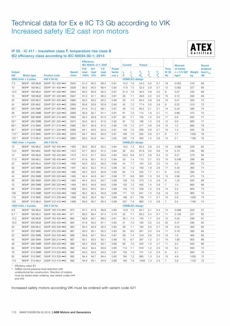
1) Efficiency class IE12) 3dB(A) sound pressure level reduction with unidirectional fan construction. Direction of rotation must be stated when ordering, see variant codes 044 and 045
Output kW Motor type Product code
Speed r/min
Efficiency IEC 60034--2-1; 2007
Power factor cos j
Current Torque
TimetE 50Hz
Moment of inertiaJ = 1/4 GD2 kgm2
Weight kg
Sound pressure level LPA dB
Full load 100%
3/4load 75%
1/2 load 50%
IN A
Is IN
TN Nm
Tl TN
Tb TN
3000 r/min = 2 poles 400 V 50 Hz CENELEC-design
7.5 M3HP 160 MLB 3GHP 161 420-••H 2943 91.0 90.5 88.4 0.91 13.2 7.6 24.3 3.0 3.7 18 0.052 216 69
10 M3HP 160 MLC 3GHP 161 430-••H 2938 90.5 90.5 89.4 0.92 17.8 7.5 32.5 2.9 3.7 12 0.062 227 69
12.5 M3HP 160 MLD 3GHP 161 440-••H 2944 92.5 92.6 92.2 0.91 21.4 7.6 40.5 2.8 4.5 8 0.07 233 69
15 M3HP 180 MLB 3GHP 181 420-••H 2947 91.0 91.1 90.2 0.91 26 7.1 48.6 2.2 3.0 15 0.13 292 69
20 M3HP 200 MLC 3GHP 201 430-••G 2960 93.2 93.2 92.2 0.90 35 7.5 64.5 2.9 3.9 10 0.21 305 72
24 M3HP 200 MLE 3GHP 201 450-••G 2959 93.8 93.8 92.9 0.90 42 7.2 77.4 3.0 3.9 9 0.22 310 72
28 1) M3HP 225 SMC 3GHP 221 230-••G 2963 91.8 91.2 89.1 0.91 49 7.0 90.2 2.1 3.1 14 0.34 385 74
36 M3HP 250 SMB 3GHP 251 220-••G 2969 92.9 92.7 91.1 0.91 61 7.2 115 1.9 2.7 11 0.66 475 74
47 2) M3HP 280 SMA 3GHP 281 210-••G 2982 93.4 92.8 91.0 0.91 80 7.1 150 1.2 3.0 17 0.8 625 77
58 2) M3HP 280 SMB 3GHP 281 220-••G 2975 93.5 93.3 91.9 0.92 97 7.0 186 1.2 2.8 12 0.9 665 77
68 2) M3HP 315 SMA 3GHP 311 210-••G 2982 93.7 92.9 91.0 0.90 116 7.2 217 0.9 2.8 10 1.2 880 78
80 2) M3HP 315 SMB 3GHP 311 220-••G 2980 94.1 93.6 92.0 0.91 134 7.0 256 0.8 2.7 10 1.4 940 78
110 2) M3HP 315 SMC 3GHP 311 230-••G 2978 94.7 94.5 93.5 0.91 183 7.0 352 0.9 2.7 8 1.7 1025 78
125 2) M3HP 315 MLA 3GHP 311 410-••G 2983 95.0 94.9 94.1 0.92 205 7.6 400 1.0 2.8 10 2.1 1190 78
1500 r/min = 4 poles 400 V 50 Hz CENELEC-design
10 M3HP 160 MLC 3GHP 162 430-••H 1463 90.5 90.9 90.2 0.84 19.5 7.3 65.2 2.8 3.4 16 0.096 226 62
13.5 M3HP 160 MLE 3GHP 162 450-••H 1470 91.7 92.0 91.2 0.84 26 8.0 87.6 3.0 3.6 14 0.13 249 68
15 M3HP 180 MLB 3GHP 182 420-••H 1473 91.5 91.7 90.9 0.83 29.5 6.9 97.2 2.6 3.3 12 0.21 279 66
17.5 M3HP 180 MLC 3GHP 182 430-••H 1477 91.9 92.1 91.3 0.84 33 7.4 113 2.7 3.2 15 0.248 298 66
24 M3HP 200 MLA 3GHP 202 410-••G 1480 93.0 93.2 92.5 0.88 44 7.7 154 2.0 3.2 14 0.3 280 73
30 M3HP 225 SMB 3GHP 222 220-••G 1481 92.3 92.3 91.3 0.89 54 7.2 193 1.8 2.6 17 0.45 365 74
36 M3HP 225 SMC 3GHP 222 230-••G 1480 93.4 93.5 92.8 0.90 64 7.4 232 1.7 3.1 8 0.53 390 74
44 M3HP 250 SMB 3GHP 252 220-••G 1482 94.4 94.6 94.1 0.89 77 6.8 283 1.3 3.0 15 0.98 470 73
58 M3HP 280 SMA 3GHP 282 210-••G 1484 94.4 94.5 93.7 0.88 100 7.6 373 1.3 2.9 8 1.25 625 68
70 M3HP 280 SMB 3GHP 282 220-••G 1484 94.5 94.9 94.6 0.89 120 7.2 450 1.4 2.9 7 1.5 665 68
84 M3HP 315 SMA 3GHP 312 210-••G 1489 95.0 95.0 94.4 0.88 145 7.0 538 1.2 2.9 14 2.3 900 73
100 M3HP 315 SMB 3GHP 312 220-••G 1489 95.2 95.3 94.8 0.88 171 7.6 641 1.2 2.9 10 2.6 960 73
115 M3HP 315 SMC 3GHP 312 230-••G 1488 95.2 95.4 95.1 0.89 196 6.7 738 1.1 2.7 10 2.9 1000 73
135 M3HP 315 MLA 3GHP 312 410-••G 1489 95.6 95.7 95.3 0.89 227 7.4 865 1.3 2.8 7 3.5 1160 73
1000 r/min = 6 poles 400 V 50 Hz CENELEC-design
6.6 M3HP 160 MLA 3GHP 163 410-••H 973 87.4 87.8 86.9 0.80 13.8 7.3 64.7 2.1 3.4 14 0.088 220 57
9.7 1) M3HP 160 MLC 3GHP 163 430-••H 971 88.0 88.4 87.4 0.79 20 7.1 95.3 2.4 3.7 11 0.126 247 65
13.2 M3HP 180 MLB 3GHP 183 420-••H 965 89.9 90.7 89.2 0.81 26.1 7.4 130 1.7 3.0 12 0.25 298 67
16.5 M3HP 200 MLB 3GHP 203 420-••G 984 91.8 92.0 91.1 0.85 31 7.0 160 3.2 3.3 25 0.47 290 65
20 M3HP 200 MLC 3GHP 203 430-••G 983 92.4 92.9 92.3 0.85 38 7.1 194 3.0 2.7 16 0.52 305 65
27 M3HP 225 SMC 3GHP 223 230-••G 987 93.0 93.1 92.3 0.83 50 8.0 261 3.2 3.4 11 0.78 380 64
33 M3HP 250 SMB 3GHP 253 220-••G 989 93.8 94.1 93.4 0.87 59 7.4 318 2.8 3.0 10 1.6 465 65
40 M3HP 280 SMA 3GHP 283 210-••G 987 93.1 93.5 93.1 0.88 70 6.7 387 1.2 2.7 15 1.85 605 66
46 M3HP 280 SMB 3GHP 283 220-••G 988 93.4 93.8 93.7 0.88 80 7.0 444 1.3 2.7 11 2.2 645 66
64 M3HP 315 SMA 3GHP 313 210-••G 992 94.2 94.4 93.9 0.85 114 7.1 616 1.2 2.5 10 3.2 830 72
76 M3HP 315 SMB 3GHP 313 220-••G 992 94.2 94.5 94.2 0.87 133 7.3 731 1.2 2.3 8 4.1 930 72
92 M3HP 315 SMC 3GHP 313 230-••G 992 94.4 94.7 94.4 0.85 164 7.2 885 1.3 2.4 15 4.9 1000 72
110 M3HP 315 MLA 3GHP 313 410-••G 992 94.9 95.1 94.8 0.86 193 7.6 1058 1.3 2.5 7 5.8 1150 72
IP 55 - IC 411 - Insulation class F, temperature rise class BIE2 efficiency class according to IEC 60034-30-1; 2014
Technical data for Ex e IIC T3 Gb according to VIK Increased safety IE2 cast iron motors
Increased safety motors according VIK must be ordered with variant code 421
110 9AKK104006 EN 02-2016 | ABB Motors and Generators
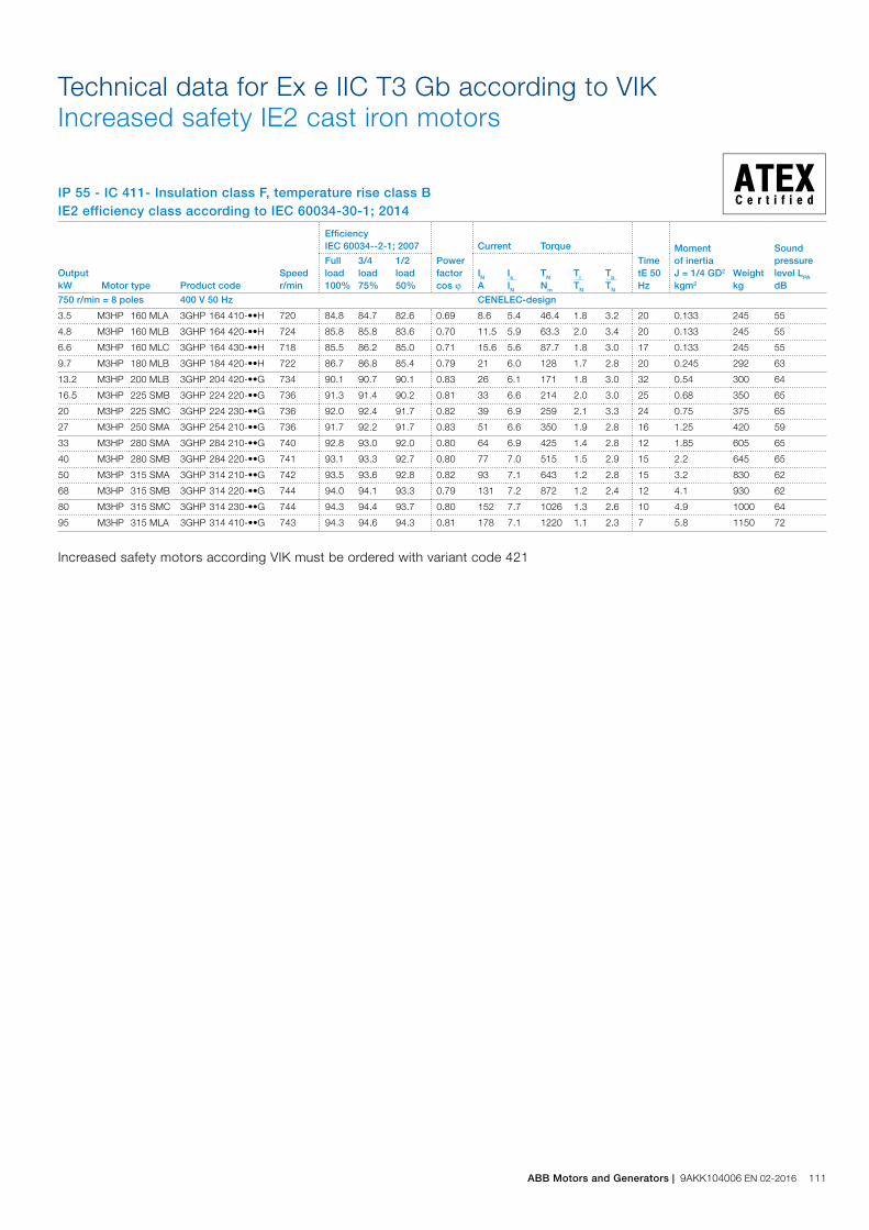
Output kW Motor type Product code
Speed r/min
Efficiency IEC 60034--2-1; 2007
Power factor cos j
Current Torque
TimetE 50Hz
Moment of inertiaJ = 1/4 GD2 kgm2
Weight kg
Sound pressure level LPA dB
Full load 100%
3/4load 75%
1/2 load 50%
IN A
Is IN
TN Nm
Tl TN
Tb TN
750 r/min = 8 poles 400 V 50 Hz CENELEC-design
3.5 M3HP 160 MLA 3GHP 164 410-••H 720 84.8 84.7 82.6 0.69 8.6 5.4 46.4 1.8 3.2 20 0.133 245 55
4.8 M3HP 160 MLB 3GHP 164 420-••H 724 85.8 85.8 83.6 0.70 11.5 5.9 63.3 2.0 3.4 20 0.133 245 55
6.6 M3HP 160 MLC 3GHP 164 430-••H 718 85.5 86.2 85.0 0.71 15.6 5.6 87.7 1.8 3.0 17 0.133 245 55
9.7 M3HP 180 MLB 3GHP 184 420-••H 722 86.7 86.8 85.4 0.79 21 6.0 128 1.7 2.8 20 0.245 292 63
13.2 M3HP 200 MLB 3GHP 204 420-••G 734 90.1 90.7 90.1 0.83 26 6.1 171 1.8 3.0 32 0.54 300 64
16.5 M3HP 225 SMB 3GHP 224 220-••G 736 91.3 91.4 90.2 0.81 33 6.6 214 2.0 3.0 25 0.68 350 65
20 M3HP 225 SMC 3GHP 224 230-••G 736 92.0 92.4 91.7 0.82 39 6.9 259 2.1 3.3 24 0.75 375 65
27 M3HP 250 SMA 3GHP 254 210-••G 736 91.7 92.2 91.7 0.83 51 6.6 350 1.9 2.8 16 1.25 420 59
33 M3HP 280 SMA 3GHP 284 210-••G 740 92.8 93.0 92.0 0.80 64 6.9 425 1.4 2.8 12 1.85 605 65
40 M3HP 280 SMB 3GHP 284 220-••G 741 93.1 93.3 92.7 0.80 77 7.0 515 1.5 2.9 15 2.2 645 65
50 M3HP 315 SMA 3GHP 314 210-••G 742 93.5 93.6 92.8 0.82 93 7.1 643 1.2 2.8 15 3.2 830 62
68 M3HP 315 SMB 3GHP 314 220-••G 744 94.0 94.1 93.3 0.79 131 7.2 872 1.2 2.4 12 4.1 930 62
80 M3HP 315 SMC 3GHP 314 230-••G 744 94.3 94.4 93.7 0.80 152 7.7 1026 1.3 2.6 10 4.9 1000 64
95 M3HP 315 MLA 3GHP 314 410-••G 743 94.3 94.6 94.3 0.81 178 7.1 1220 1.1 2.3 7 5.8 1150 72
IP 55 - IC 411- Insulation class F, temperature rise class BIE2 efficiency class according to IEC 60034-30-1; 2014
Technical data for Ex e IIC T3 Gb according to VIK Increased safety IE2 cast iron motors
Increased safety motors according VIK must be ordered with variant code 421
ABB Motors and Generators | 9AKK104006 EN 02-2016 111
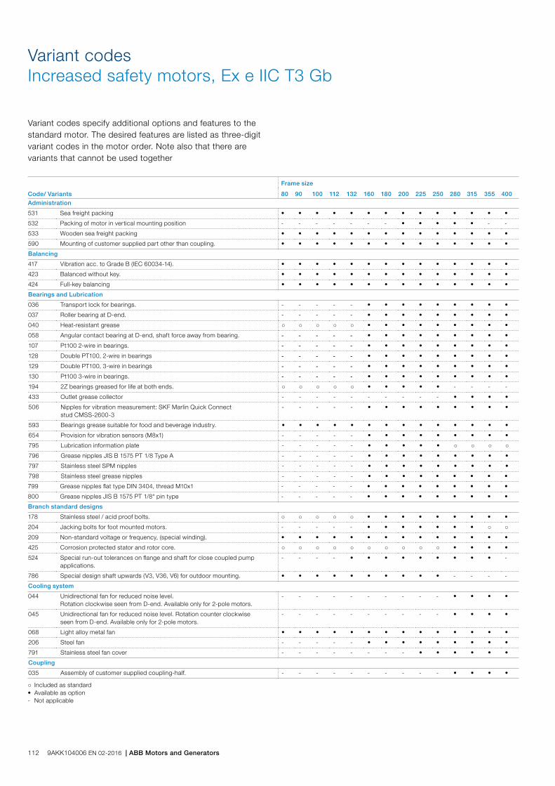
Code/ Variants
Frame size
80 90 100 112 132 160 180 200 225 250 280 315 355 400Administration
531 Sea freight packing • • • • • • • • • • • • • •
532 Packing of motor in vertical mounting position - - - - - - - • • • • • - -
533 Wooden sea freight packing • • • • • • • • • • • • • •
590 Mounting of customer supplied part other than coupling. • • • • • • • • • • • • • •
Balancing
417 Vibration acc. to Grade B (IEC 60034-14). • • • • • • • • • • • • • •
423 Balanced without key. • • • • • • • • • • • • • •
424 Full-key balancing • • • • • • • • • • • • • •
Bearings and Lubrication
036 Transport lock for bearings. - - - - - • • • • • • • • •
037 Roller bearing at D-end. - - - - - • • • • • • • • •
040 Heat-resistant grease ○ ○ ○ ○ ○ • • • • • • • • •
058 Angular contact bearing at D-end, shaft force away from bearing. - - - - - • • • • • • • • •
107 Pt100 2-wire in bearings. - - - - - • • • • • • • • •
128 Double PT100, 2-wire in bearings - - - - - • • • • • • • • •
129 Double PT100, 3-wire in bearings - - - - - • • • • • • • • •
130 Pt100 3-wire in bearings. - - - - - • • • • • • • • •
194 2Z bearings greased for life at both ends. ○ ○ ○ ○ ○ • • • • • - - - -
433 Outlet grease collector - - - - - - - - - - • • • •
506 Nipples for vibration measurement: SKF Marlin Quick Connect stud CMSS-2600-3
- - - - - • • • • • • • • •
593 Bearings grease suitable for food and beverage industry. • • • • • • • • • • • • • •
654 Provision for vibration sensors (M8x1) - - - - - • • • • • • • • •
795 Lubrication information plate - - - - - • • • • • ○ ○ ○ ○
796 Grease nipples JIS B 1575 PT 1/8 Type A - - - - - • • • • • • • • •
797 Stainless steel SPM nipples - - - - - • • • • • • • • •
798 Stainless steel grease nipples - - - - - • • • • • • • • •
799 Grease nipples flat type DIN 3404, thread M10x1 - - - - - • • • • • • • • •
800 Grease nipples JIS B 1575 PT 1/8“ pin type - - - - - • • • • • • • • •
Branch standard designs
178 Stainless steel / acid proof bolts. ○ ○ ○ ○ ○ • • • • • • • • •
204 Jacking bolts for foot mounted motors. - - - - - • • • • • • • ○ ○
209 Non-standard voltage or frequency, (special winding). • • • • • • • • • • • • • •
425 Corrosion protected stator and rotor core. ○ ○ ○ ○ ○ ○ ○ ○ ○ ○ • • • •
524 Special run-out tolerances on flange and shaft for close coupled pump applications.
- - - - • • • • • • • • • -
786 Special design shaft upwards (V3, V36, V6) for outdoor mounting. • • • • • • • • • • - - - -
Cooling system
044 Unidirectional fan for reduced noise level. Rotation clockwise seen from D-end. Available only for 2-pole motors.
- - - - - - - - - - • • • •
045 Unidirectional fan for reduced noise level. Rotation counter clockwise seen from D-end. Available only for 2-pole motors.
- - - - - - - - - - • • • •
068 Light alloy metal fan • • • • • • • • • • • • • •
206 Steel fan - - - - - • • • • • • • • •
791 Stainless steel fan cover - - - - - - - - • • • • • •
Coupling
035 Assembly of customer supplied coupling-half. - - - - - - - - - - • • • •
Variant codesIncreased safety motors, Ex e IIC T3 Gb
Variant codes specify additional options and features to the standard motor. The desired features are listed as three-digit variant codes in the motor order. Note also that there are variants that cannot be used together
○ Included as standard• Available as option- Not applicable
112 9AKK104006 EN 02-2016 | ABB Motors and Generators
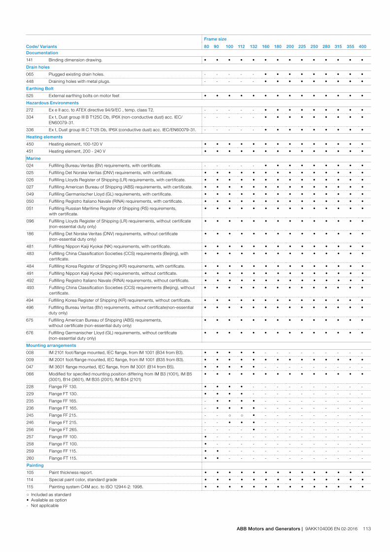
Code/ Variants
Frame size
80 90 100 112 132 160 180 200 225 250 280 315 355 400Documentation
141 Binding dimension drawing. • • • • • • • • • • • • • •
Drain holes
065 Plugged existing drain holes. - - - - - • • • • • • • • •
448 Draining holes with metal plugs. - - - - - • • • • • • • • •
Earthing Bolt
525 External earthing bolts on motor feet • • • • • • • • • • • • • •
Hazardous Environments
272 Ex e II acc. to ATEX directive 94/9/EC , temp. class T2. - - - - - • • • • • • • • •
334 Ex t, Dust group III B T125C Db, IP6X (non-conductive dust) acc. IEC/EN60079-31.
- - - - - • • • • • • • • •
336 Ex t, Dust group III C T125 Db, IP6X (conductive dust) acc. IEC/EN60079-31. - - - - - • • • • • • • • •
Heating elements
450 Heating element, 100-120 V • • • • • • • • • • • • • •
451 Heating element, 200 - 240 V • • • • • • • • • • • • • •
Marine
024 Fulfilling Bureau Veritas (BV) requirements, with certificate. - - - - - • • • • • • • • •
025 Fulfilling Det Norske Veritas (DNV) requirements, with certificate. • • • • • • • • • • • • • •
026 Fulfilling Lloyds Register of Shipping (LR) requirements, with certificate. • • • • • • • • • • • • • •
027 Fulfilling American Bureau of Shipping (ABS) requirements, with certificate. • • • • • • • • • • • • • •
049 Fulfilling Germanischer Lloyd (GL) requirements, with certificate. • • • • • • • • • • • • • •
050 Fulfilling Registro Italiano Navale (RINA) requirements, with certificate. • • • • • • • • • • • • • •
051 Fulfilling Russian Maritime Register of Shipping (RS) requirements, with certificate.
• • • • • • • • • • • • • •
096 Fulfilling Lloyds Register of Shipping (LR) requirements, without certificate (non-essential duty only)
• • • • • • • • • • • • • •
186 Fulfilling Det Norske Veritas (DNV) requirements, without certificate (non-essential duty only)
• • • • • • • • • • • • • •
481 Fulfilling Nippon Kaiji Kyokai (NK) requirements, with certificate. • • • • • • • • • • • • • •
483 Fulfilling China Classification Societies (CCS) requirements (Beijing), with certificate.
• • • • • • • • • • • • • •
484 Fulfilling Korea Register of Shipping (KR) requirements, with certificate. • • • • • • • • • • • • • •
491 Fulfilling Nippon Kaiji Kyokai (NK) requirements, without certificate. • • • • • • • • • • • • • •
492 Fulfilling Registro Italiano Navale (RINA) requirements, without certificate. • • • • • • • • • • • • • •
493 Fulfilling China Classification Societies (CCS) requirements (Beijing), without certificate.
• • • • • • • • • • • • • •
494 Fulfilling Korea Register of Shipping (KR) requirements, without certificate. • • • • • • • • • • • • • •
496 Fulfilling Bureau Veritas (BV) requirements, without certificate(non-essential duty only)
• • • • • • • • • • • • • •
675 Fulfilling American Bureau of Shipping (ABS) requirements, without certificate (non-essential duty only)
• • • • • • • • • • • • • •
676 Fulfilling Germanischer Lloyd (GL) requirements, without certificate (non-essential duty only)
• • • • • • • • • • • • • •
Mounting arrangements
008 IM 2101 foot/flange mounted, IEC flange, from IM 1001 (B34 from B3). • • • • • - - - - - - - - -
009 IM 2001 foot/flange mounted, IEC flange, from IM 1001 (B35 from B3). • • • • • • • • • • • • • •
047 IM 3601 flange mounted, IEC flange, from IM 3001 (B14 from B5). • • • • • - - - - - - - - -
066 Modified for specified mounting position differing from IM B3 (1001), IM B5 (3001), B14 (3601), IM B35 (2001), IM B34 (2101)
• • • • • • • • • • • • • •
228 Flange FF 130. • • • • - - - - - - - - - -
229 Flange FT 130. • • • • - - - - - - - - - -
235 Flange FF 165. - • • • • - - - - - - - - -
236 Flange FT 165. - • • • • - - - - - - - - -
245 Flange FF 215. - - ○ ○ • - - - - - - - - -
246 Flange FT 215. - - • • • - - - - - - - - -
256 Flange FT 265. - - - - • - - - - - - - - -
257 Flange FF 100. • - - - - - - - - - - - - -
258 Flange FT 100. • - - - - - - - - - - - - -
259 Flange FF 115. • • - - - - - - - - - - - -
260 Flange FT 115. • • - - - - - - - - - - - -
Painting
105 Paint thickness report. • • • • • • • • • • • • • •
114 Special paint color, standard grade • • • • • • • • • • • • • •
115 Painting system C4M acc. to ISO 12944-2: 1998. • • • • • • • • • • • • • •
○ Included as standard• Available as option- Not applicable
ABB Motors and Generators | 9AKK104006 EN 02-2016 113
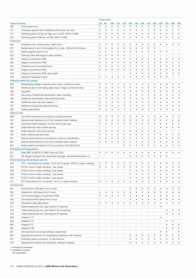
Code/ Variants
Frame size
80 90 100 112 132 160 180 200 225 250 280 315 355 400168 Primer paint only. • • • • • • • • • • • • • •
710 Thermally sprayed zink metallizing with acrylic top coat • • • • • • • • • • • • • •
711 Painting system C5-M very high, acc. to ISO 12944-2:1998 • • • • • • • • • • • • • •
754 Painting system C5M acc. to ISO 12944-2:1998 • • • • • • • • • • • • • •
Protection
005 Protective roof, vertical motor, shaft down. • • • • • • • • • • • • • •
072 Radial seal at D-end. Not possible for 2-pole , 280 and 315 frames • • • • • • • • • • - - - -
073 Sealed against oil at D-end. • • • • • • • • • • • • - -
076 Draining holes with plugs in open position. • • • • • ○ ○ ○ ○ ○ ○ ○ ○ ○
158 Degree of protection IP65. • • • • • • • • • • • • • •
250 Degree of protection IP66. • • • • • • • • • • • • • •
401 Protective roof, horizontal motor. • • • • • • • • • • • • • •
403 Degree of protection IP56. • • • • • • • • • • • • • •
434 Degree of protection IP56, open deck. - - - - - • • • • • • • • •
783 Labyrinth sealing at D-end. • • • • • • • • • • • • ○ ○
Rating & instruction plates
002 Restamping voltage, frequency and output, continuous duty. • • • • • • • • • • • • • •
004 Additional text on std rating plate (max 12 digits on free text line). • • • • • • • • • • • • • •
126 Tag plate • • • • • • • • • • • • • •
135 Mounting of additional identification plate, stainless. • • • • • • • • • • • • • •
139 Additional identification plate delivered loose. • • • • • • • • • • • • • •
159 Additional plate with text „Made in ....“ • • • • • • • • • • • • • •
161 Additional rating plate delivered loose. • • • • • • • • • • • • • •
528 Rating plate sticker • • • • • • • • • • • • • •
Shaft & rotor
069 Two shaft extensions according to catalog drawings. • • • • • • • • • • • • • •
070 Special shaft extension at D-End, standard shaft material • • • • • • • • • • • • • •
155 Cylindrical shaft extension, D-end, without key-way. • • • • • • • • • • • • • •
164 Shaft extension with closed keyway ○ ○ ○ ○ ○ ○ ○ ○ ○ ○ • • • •
165 Shaft extension with open keyway • • • • • • • • • • ○ ○ ○ ○
410 Shaft material stainless steel • • • • • • • • • • • • • •
591 Special shaft extension according to customer specification. • • • • • • • • • • • • • •
600 Special shaft extension at N-end, standard shaft material. • • • • • • • • • • • • • •
630 Shaft material certificate 3.1/3.2 according to EN10204:2004 - - - - • • • • • • • • • •
Standards and Regulations
251 Shell DEP 33.66.05.31-GEN. February 2012. • • • • • • • • • • • • • •
421 VIK design (Verband der Industriellen Energie- und Kraftwirtschaft e.V.). - - - - - • • • • • • • - -
Stator winding temperature sensors
440 PTC - thermistors (3 in series, 110ºC & 3 in series, 130ºC), in stator winding. • • • • • • • • • • • • • •
445 Pt100 2-wire in stator winding, 1 per phase • • • • • • • • • • • • • •
446 Pt100 2-wire in stator winding, 2 per phase - - - - - • • • • • • • • •
502 Pt100 3-wire in stator winding, 1 per phase - - - - - • • • • • • • • •
503 Pt100 3-wire in stator winding, 2 per phase - - - - - • • • • • • • • •
511 PTC thermistors (2 x 3 in series), 130 ºC, in stator winding • • • • • • • • • • • • • •
Terminal box
021 Terminal box LHS (seen from D-end). - - - - - • • • • • • • • •
022 Cable entry LHS (seen from D-end). • • • • • • • • • • • • • •
157 Terminal box degree of protection IP65. • • • • • • • • • • • • • •
180 Terminal box RHS (seen from D-end). - - - - - • • • • • • • • •
230 Standard metal cable gland. • • • • • • • • • • • • • •
277 Cable sealing end unit, size small for C-opening - - - - - - - - - - • - - -
278 Cable sealing end unit, size medium for D-opening - - - - - - - - - - - • • •
279 Cable sealing end unit, size large for D-opening - - - - - - - - - - - • • •
292 Adapter C-C - - - - - - - - - - • - - -
293 Adapter D-D - - - - - - - - - - - • • -
294 Adapter E-D - - - - - - - - - - - • • •
295 Adapter E-2D - - - - - - - - - - - • • •
351 Terminal block turned according to cable entry - - - - - - - - - - • • - •
380 Separate terminal box for temperature detectors, std. material - - - - - • • • • • • • • •
413 Extended cable connection, no terminal box. - - - - - • • • • • • • • •
418 Separate terminal box for auxiliaries, standard material. - - - - - • • • • • • • • •
○ Included as standard• Available as option- Not applicable
114 9AKK104006 EN 02-2016 | ABB Motors and Generators

Code/ Variants
Frame size
80 90 100 112 132 160 180 200 225 250 280 315 355 400466 Terminal box at N-end. - - - - - - - • • • • • • •
468 Cable entry from D-end. • • • • • • • • • • • • • •
469 Cable entry from N-end. • • • • • • • • • • • • • •
526 Existing cable entries plugged • • • • • • • • • • • • • -
553 Terminal box degree of protection IP66. • • • • • • • • • • • • • •
554 Painted steel flange for cable glands drilled and tapped according to order. • • • • • • • • • • • • • •
555 Aluminum flange for cable glands drilled and tapped according to order. • • • • • • • • • • • • • •
556 Aluminum cable glands mounted according to order. • • • • • - - • • • • • • •
557 Nickel plated cable glands mounted according to order. • • • • • • • • • • • • • •
567 Separate terminal box material: cast Iron - - - - - ○ ○ • • • • • • •
568 Separate terminal box for heating elements, std. material - - - - - • • • • • • • • •
727 Stainless steel flange for cable glands drilled and tapped according to order. • • • • • • • • • • • • • •
729 Aluminum non-drilled flange for cable glands • • • • • • • • • • • • • •
730 Prepared for NPT cable glands. • • • • • • • • • • • • • •
731 Two standard metal cable glands, musta täppä 80-400 • • • • • • • • • • • • • •
734 Standard cable gland, Ex d IIC • • • • • • • • • • • • • •
743 Painted non-drilled flange in steel for cable glands • • • • • • • • • • • • • •
744 Stainless steel non-drilled flange for cable glands. • • • • • • • • • • • • • •
745 Painted steel flange equipped with nickel plated brass cable glands • • • • • • • • • • • • • •
746 Stainless steel cable flange equipped with standard nickel plated brass cable glands
• • • • • • • • • • • • • •
Testing
145 Type test report from a catalogue motor, 400V 50Hz. • • • • • • • • • • • • • •
146 Type test with report for one motor from specific delivery batch. • • • • • • • • • • • • • •
148 Routine test report. • • • • • • • • • • • • • •
150 Customer witnessed testing. Specify test procedure with other codes. • • • • • • • • • • • • • •
222 Torque/speed curve, type test and multi-point load test with report for one mo-tor from specific delivery batch.
• • • • • • • • • • • • • •
560 Shaft voltage test. • • • • • • • • • • • • • •
561 Overspeed test. • • • • • • • • • • • • • •
562 Overvoltage test. • • • • • • • • • • • • • •
760 Vibration level test • • • • • • • • • • • • • •
761 Vibration spectrum test for one motor from specific delivery batch. • • • • • • • • • • • • • •
762 Noise level test for one motor from specific delivery batch. • • • • • • • • • • • • • •
763 Noise spectrum test for one motor from specific delivery batch. - - - - - • • • • • • • • •
○ Included as standard• Available as option- Not applicable
ABB Motors and Generators | 9AKK104006 EN 02-2016 115

Mechanical designMotor frame and drain holes
M00
0178
Open
Closed
Open
Motor frameThe motor frame, end shields and main terminal box are made of cast iron. Motors in frame size 200 and larger have integrated feet for rigid and vibration free mounting, motors in frame size 80-180 have detachable feet made of forged steel for maximum flexibility and rigidity.
Motors can be supplied for foot mounting, flange mounting, and combinations of these.
Drain holesIncreased safety motors in frame size 200-400 are provided with drain holes fitted with plugs as standard. The plugs are made of plastic material and delivered in open position. Drain holes and plugs are available for frame size 80 to 180 as an option, please refer to variant code section.
It’s recommended that motors that will be operated in very humid or wet environments, and especially under intermittent duty, should be provided with drain holes with plugs to ensure that water possibly condensed inside the enclosure can easily be drained.
When mounting arrangement differs from foot mounted IM B3, mention variant code 066 when ordering to ensure the drain plug is mounted in the lowest position.
Lifting lugsThe motors are provided as standard with lifting lugs according to table below. For improved lifting possibilities can variant code 305 be added, please refer to the variant code section for information about availability.
Frame size
Type of lugs Foot mounted motors Flange mounted motors
80 Detachable lifting eye
1 pcs close to terminal box 1 pcs close to terminal box
90-112 Integrated in casting
2 pcs close to terminal box on top
2 pcs close to terminal box
132 Integrated in casting
2 pcs on top of motor diagonally placed, integrated in frame casting
2 pcs on top of motor diagonally placed, integrated in frame casting
160 Detachable eye bolt
Several mounting locations for lugs on the frame, 2 pcs M12 delivered with each motor
Several mounting locations for lugs on the frame, 2 pcs M12 delivered with each motor
180 Detachable eye bolt
Several mounting locations for lugs on the frame, 2 pcs M16 delivered with each motor
Several mounting locations for lugs on the frame, 2 pcs M16 delivered with each motor
225-250 Integrated in casting
2 pcs on top of motor diagonally placed
2 pcs at N-end, 2 pcs at D-end diagonally placed
280, 315 Detachable eye bolt
1 pcs close to terminal box on top, size M24
Locations for eye bolts: 4 pcs at N-end and 4 pcs at D-end, one location on top close to terminal box. 2 pcs eye bolts size M24 delivered with each motor
355 Detachable eye bolt
1 pcs close to terminal box on top, size M30
Locations for eye bolts: 4 pcs at N-end and 4 pcs at D-end, one location on top close to terminal box. 2 pcs eye bolts size M30 delivered with each motor
400 Detachable eye bolt
1 pcs close to terminal box on top, size M36
Locations for eye bolts: 4 pcs at N-end and 4 pcs at D-end, one location on top close to terminal box. 2 pcs eye bolts size M36 delivered with each motor
116 9AKK104006 EN 02-2016 | ABB Motors and Generators

Heating elements
Heating elements are installed on stator winding coil heads to keep the winding free of corrosion in humid conditions. The power of the heating elements is shown in the table. You can order heating elements with variant code 450 or 451.
Motor size 80 90 100 112 132 160 180
Power (W) 25 25 25 25 25 25 25
Motor size 200 225 250 280 315 355 400
Power (W) 25 60 60 60 2x60 2x60 2x60
Motors for marine applications mounted on open deck may have heating element powers differing from the ones shown in this table.
ABB Motors and Generators | 9AKK104006 EN 02-2016 117

Bearings
ABB’s increased safety motors are normally fitted with single-row deep-groove grease lubricated ball bearings, as shown in the table below.
If the bearing at the D-end is replaced with a roller bearing (NU- or NJ-), higher radial forces can be handled. Roller bearings are suitable for belt-drive applications and can be ordered with variant code 037.
When high axial forces are involved, angular-contact ball bearings should be used. When ordering a motor with an angular-contact ball bearing, specify also the method of mounting and the direction and magnitude of axial force to ensure that optimal bearing system design is chosen. The variant codes for ordering angular-contact ball bearings at D-end are 058 and 060.
Standard and alternative designs
Motor size Number of poles
Standard design Alternative design D-end
Deep groove ball bearings Roller bearings (037) Angular contact ball bearing (058, 060)
D-end N-end D-end D-end
80 2-8 6205-2Z/C3 6204-2Z/C3 NA NA
90 2-8 6205-2Z/C3 6205-2Z/C3 NA NA
100 2-8 6206-2Z/C3 6206-2Z/C3 NA NA
112 2-8 6206-2Z/C3 6206-2Z/C3 NA NA
132 2-8 6208-2Z/C3 6208-2Z/C3 NA NA
160 2-12 6309/C3 6309/C3 NU 309 ECP/C3 7309 B
180 2-12 6310/C3 6310/C3 NU 310 ECP/C3 7310 B
200 2 6312M/C3 6310M/C3 NU 312 ECP/C3 7312 B
200 4-12 6312/C3 6310/C3 NU 312 ECP/C3 7312 B
225 2 6313M/C3 6312M/C3 NU 313 ECP/C3 7313 B
225 4-12 6313/C3 6312/C3 NU 313 ECP/C3 7313 B
250 2 6315M/C3 6313M/C3 NU 315 ECP/C3 7315 B
250 4-12 6315/C3 6313/C3 NU 315 ECP/C3 7315 B
280 2 6316/C3 6316/C3 1) 7316 B
4-12 6316/C3 6316/C3 NU 316 ECP/C3 7316 B
315 2 6316/C3 6316/C3 1) 7316 B
4-12 6319/C3 6316/C3 NU 319 ECP/C3 7319 B
355 2 6316M/C3 6316M/C3 1) 7316 B
4-12 6322/C3 6316/C3 NU 322 ECP/C3 7322 B
400 2 6317M/C3 6317M/C3 1) 7317 B
4-12 6324/C3 6319/C3 NU 324 ECP/C3 7324 B1) On request
Axially-locked bearingsAll motors with deep groove ball bearings are equipped as standard with an axially locked bearing at the D-end.
Transport lockingMotors with roller bearings or an angular-contact ball bearing are fitted with a transport lock before dispatch to prevent damage to bearings during transport. A warning label is attached to motors when transport locking is used.
Locking may also be fitted in other cases if severe transport conditions are expected.
118 9AKK104006 EN 02-2016 | ABB Motors and Generators

Motor sizeNumber of poles
Standard design Alternative design
D-end N-end Radial seal at D-end (variant code 072) 1) Labyrinth seal at D-end (variant code 783) 1)
80 2-8 Gamma seal Gamma seal Radial seal Labyrinth seal
90 2-8 Gamma seal Gamma seal Radial seal Labyrinth seal
100 2-8 Gamma seal Gamma seal Radial seal Labyrinth seal
112 2-8 Gamma seal Gamma seal Radial seal Labyrinth seal
132 2-8 Gamma seal Gamma seal Radial seal Labyrinth seal
160 2-8 Gamma seal Gamma seal Radial seal Labyrinth seal
180 2-8 Gamma seal Gamma seal Radial seal Labyrinth seal
200 2-8 Gamma seal Gamma seal Radial seal Labyrinth seal
225 2-8 Gamma seal Gamma seal Radial seal Labyrinth seal
250 2-8 Gamma seal Gamma seal Radial seal Labyrinth seal
280 2 Labyrinth seal V-ring NA Standard
4-8 V-ring V-ring NA Labyrinth seal
315 2 Labyrinth seal V-ring NA Standard
4-8 V-ring V-ring NA Labyrinth seal
355 2-12 Labyrinth seal V-ring NA Standard
400 2 Labyrinth seal Labyrinth seal NA Standard
400 4-12 Labyrinth seal V-ring NA Standard1) N-end bearing seal of standard design, special N-end bearing seal arrangements on request
Bearing seals for motor sizes 80-400
Standard design
D-end
N-end
Motor size,seal type D-end / N-end
80-132, gamma/gamma seal
160-250, gamma/gamma seal
280, 315 2pole, 335 all pole numbers and 400 4-12 pole, labyrinth / V-ring seal
400 2-pole, labyrinth/labyrinth seal
Alternative design
D-end
N-end
Motor size, seal type D-end / N-end
80-132, VC072 radial/gamma seals
80-132, VC783 labyrinth/gamma seals
160-250, VC072 radial/gamma seals
160-250, VC783 labyrinth/gamma seals
Bearing sealsTable below present the standard and alternative and types of bearing seals per motor size
ABB Motors and Generators | 9AKK104006 EN 02-2016 119

Bearing life and lubricationThe nominal life L10h of a bearing is defined according to ISO 281 as the number of operating hours achieved or exceeded by 90 % of identical bearings in a large test series under specified conditions. 50 % of bearings achieve at least five times this lifetime. The calculated bearing life L10h for power transmission by means of coupling is for horizontally mounted motors in sizes up to 315 ≥ 100,000 hours.
LubricationOn delivery, motors in frame size 160 and above are pre-lubricated with high-quality grease. Before first start-up, see instructions for re-lubrication and recommended grease in the installation, operation, maintenance and safety manual for low voltage motors for explosive atmospheres delivered together with the motor, or see the lubrication plate on the motor.
Motors with bearings greased for lifeMotors in frame sizes 80-132 are equipped with bearings greased for life, while this is available as an option for frame sizes 160-250. Bearings are lubricated with high-quality, high-temperature grease. Bearing types are stated on the rating plate.
The approximate lifetime of bearings in four-pole motors is about 40 0000 duty hours. Lifetime is subject to the load conditions of the application run by the motor.
Motors with re-lubrication nipplesIn frame sizes 160-400, the bearing system is provided with valve discs to ease lubrication. Motors are lubricated while running. The grease outlet opening has closing valves at both ends. These should be opened before greasing and closed 1-2 hours after re-greasing. This ensures that the construction is tight and bearings remain dust- and dirt-free.
A grease-collection method can be used optionally.
The following tables show lubrication intervals according to the L1 principle for various nominal speeds in 25 °C ambient temperature. These values apply to horizontally mounted motors (B3) with 80 °C bearing temperature and high-quality grease containing lithium-complex soap and mineral or PAO-oil.
Frame size
Amount of grease g/bearing
Amount of grease g/N-end
Speed 3600 r/min
Speed 3000 r/min
Speed 1800 r/min
Speed 1500 r/min
Speed 1000 r/min
Speed 500-900 r/min
Ball bearings
Lubrication intervals in duty hours
160 13 13 7100 8900 14300 16300 20500 21600
180 15 15 6100 7800 13100 15100 19400 20500
200 20 15 4300 5900 11000 13000 17300 18400
225 23 20 3600 5100 10100 12000 16400 17500
250 30 23 2400 3700 8500 10400 14700 15800
280 35 35 1900 3200 - - - -
280 40 40 - - 7800 9600 13 900 15 000
315 35 35 1900 3200 - - - -
315 55 40 - - 5900 7600 11 800 12 900
355 35 35 1900 3200 - - - -
355 70 40 - - 4000 5600 9600 10 700
400 40 40 1500 2700 - - - -
400 85 55 - - 3200 4700 8600 9700
450 95 70 - - 2500 3900 7700 8700
Lubrication intervals in duty hours for ball bearings
Lubrication intervals in duty hours for roller bearings
Framesize
Amountof greaseg/bearing
Amountof greaseg/N-end
OutputkW
Speed3600r/min
Speed3000r/min
OutputkW
Speed1800r/min
Speed1500r/min
OutputkW
Speed1000r/min
OutputkW
Speed500-900r/min
Roller bearings
Lubrication intervals in duty hours
160 13 13 all 3600 4500 all 7200 8100 all 10300 all 10800
180 15 15 3000 3900 all 6600 7500 all 9700 all 10200
200 20 15 2100 3000 all 5500 6500 all 8600 all 9200
225 23 20 1800 1600 all 5100 6000 all 8200 all 8700
250 30 23 1200 1900 all 4200 5200 all 7300 all 7900
280 40 40 - - all 4000 5300 all 7000 all 8500
315 55 40 - - all 2900 3800 all 5900 all 6500
120 9AKK104006 EN 02-2016 | ABB Motors and Generators

Radial forces
Pulley diameterWhen the desired bearing life has been determined, the minimum permissible pulley diameter can be calculated with FR as follows:
D =1.9 • 107 • K • P
n • FR
Where:
D: pulley diameter, mm
P: power requirement, kW
n: motor speed, r/min.
K: belt tension factor, dependent on belt type and type of duty. A common value for V-belts is 2.5
FR: permissible radial force, refer to tables below.
Permissible loading on the shaftThe following table shows permissible radial forces on the shaft in Newtons, assuming zero axial force, a 25 °C ambient temperature, and normal conditions. The values are given for a calculated bearing life L10h of 40 000 hours per motor size.
These calculated values further assume mounting position IM B3 (foot-mounted), with force directed sideways. In some cases, the strength of the shaft together with flame path dimensions affects permissible forces.
FR = FX0 -
X (FX0 - FXmax)E
Where:
E: length of the shaft extension in the standard version
Permissible radial forces, motor sizes 80-132
Permissible loads of simultaneous radial and axial forces can be supplied on request.
If the radial force is applied between points X0 and Xmax, the permissible force FR can be calculated with the following formula:
Motor size No. of poles
Length of shaft extension E (mm)
Basic design with deep groove ball bearings L10h=40,000h Roller bearings
FX0(N) FXmax(N) FX0(N) FX0(N)
80 2 40 619 524 NA NA
4 40 780 663 NA NA
6 40 893 759 NA NA
8 40 983 834 NA NA
90 2 50 561 473 NA NA
4 50 803 677 NA NA
6 50 919 775 NA NA
8 50 1011 853 NA NA
100 2 60 553 457 NA NA
4 60 1050 868 NA NA
6 60 1267 1047 NA NA
8 60 1395 1153 NA NA
112 2 60 553 457 NA NA
4 60 1050 868 NA NA
6 60 1267 1047 NA NA
8 60 1394 1152 NA NA
132 2 80 1354 1112 NA NA
4 80 1772 1454 NA NA
6 80 2028 1665 NA NA
8 80 2234 1833 NA NA
ABB Motors and Generators | 9AKK104006 EN 02-2016 121

Permissible radial forces, motor sizes 160 to 400
Motor size Poles
Lengtof shaftextensionE (mm)
Basic design with deep groove ball bearings L10h=40,000h Roller bearings L10h=40,000h
Mounting arrangement IM B3 Mounting arrangement IM B3
FX0 (N) FXmax (N) FX0 (N) FXmax (N)
160 ML_ 2 110 2530 2120 6400 3160
4 110 3180 2670 7880 3130
6 110 3650 3060 8900 3140
8 110 4020 3370 9700 3150
180 ML_ 2 110 2900 2440 6970 4380
4 110 3660 3080 8580 4360
6 110 4190 3520 9700 4360
8 110 4620 3880 10570 4370
200 ML_ 2 110 3830 3160 9500 7100
4 110 4830 3980 11710 7090
6 110 5520 4550 13230 7080
8 110 6080 5010 14420 7090
225 SM_ 2 110 4350 3660 11650 7090
4 140 5490 4420 14340 7340
6 140 6280 5060 16190 7330
8 140 6920 5570 17660 7330
250 SM_ 2 140 4390 4350 15420 7360
4 140 6790 5480 18980 9320
6 140 7760 6270 21440 9330
8 140 8550 6900 23370 9320
280 SM_ 2 140 5840 4900 16500 6350
4 140 7260 6110 20100 9690
6 140 8300 6980 22690 9680
8 140 9150 7700 24740 9690
315 SM_ 2 140 5810 4960 16540 6280
4 170 9030 7470 26590 10170
6 170 10310 8530 30030 10160
8 170 11360 9400 32740 10100
315 ML_ 2 140 5850 5080 16710 6200
4 170 9000 7620 26580 14570
6 170 10270 8700 30010 14580
8 170 11330 9590 32720 14510
355 SM_ 2 140 5790 5090 16790 7470
4 210 11930 9890 36660 14590
6 210 13630 11300 41390 14530
8 210 15050 12470 45140 14460
355 ML_ 2 140 5770 5120 16880 7110
4 210 11980 10090 36960 14290
6 210 13650 11500 41720 14210
8 210 15090 12710 45503 14110
355 LK_ 2 140 5670 5140 17030 6570
4 210 12020 10420 37470 13850
6 210 13680 11860 42290 13660
8 210 15160 13150 46130 13510
400 L_ 2 170 4550 3970 19390 8760
4 210 12120 10550 43040 18600
6 210 13750 11970 48570 17980
8 210 15280 13310 52990 18180
400 LK_ 2 170 4450 3970 19390 8760
4 210 12120 10550 43040 18600
6 210 13750 11970 48570 17980
8 210 15280 13310 52990 18180
122 9AKK104006 EN 02-2016 | ABB Motors and Generators
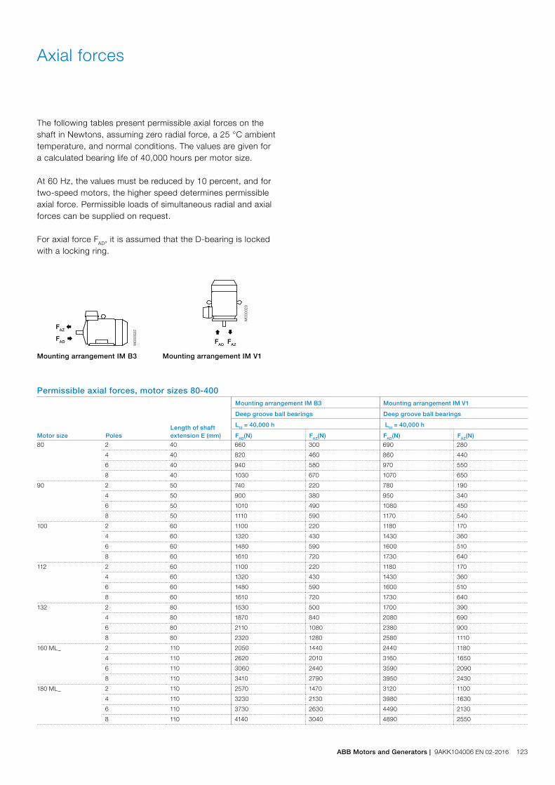
The following tables present permissible axial forces on the shaft in Newtons, assuming zero radial force, a 25 °C ambient temperature, and normal conditions. The values are given for a calculated bearing life of 40,000 hours per motor size.
At 60 Hz, the values must be reduced by 10 percent, and fortwo-speed motors, the higher speed determines permissible axial force. Permissible loads of simultaneous radial and axial forces can be supplied on request.
For axial force FAD, it is assumed that the D-bearing is locked with a locking ring.
Axial forces
Permissible axial forces, motor sizes 80-400
Ç
FAD
M00
0023
È
FAZFAD Æ
M00
0022
FAZ Å
Mounting arrangement IM B3 Mounting arrangement IM V1
Motor size PolesLength of shaft extension E (mm)
Mounting arrangement IM B3 Mounting arrangement IM V1
Deep groove ball bearings Deep groove ball bearings
L10 = 40,000 h L10 = 40,000 h
FAD(N) FAZ(N) FAD(N) FAZ(N)
80 2 40 660 300 690 280
4 40 820 460 860 440
6 40 940 580 970 550
8 40 1030 670 1070 650
90 2 50 740 220 780 190
4 50 900 380 950 340
6 50 1010 490 1080 450
8 50 1110 590 1170 540
100 2 60 1100 220 1180 170
4 60 1320 430 1430 360
6 60 1480 590 1600 510
8 60 1610 720 1730 640
112 2 60 1100 220 1180 170
4 60 1320 430 1430 360
6 60 1480 590 1600 510
8 60 1610 720 1730 640
132 2 80 1530 500 1700 390
4 80 1870 840 2080 690
6 80 2110 1080 2380 900
8 80 2320 1280 2580 1110
160 ML_ 2 110 2050 1440 2440 1180
4 110 2620 2010 3160 1650
6 110 3060 2440 3590 2090
8 110 3410 2790 3950 2430
180 ML_ 2 110 2570 1470 3120 1100
4 110 3230 2130 3980 1630
6 110 3730 2630 4490 2130
8 110 4140 3040 4890 2550
ABB Motors and Generators | 9AKK104006 EN 02-2016 123
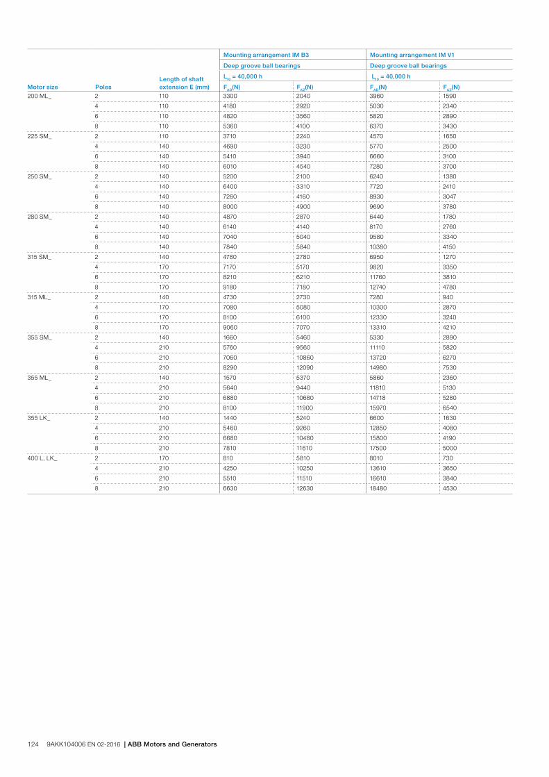
Motor size PolesLength of shaft extension E (mm)
Mounting arrangement IM B3 Mounting arrangement IM V1
Deep groove ball bearings Deep groove ball bearings
L10 = 40,000 h L10 = 40,000 h
FAD(N) FAZ(N) FAD(N) FAZ(N)
200 ML_ 2 110 3300 2040 3960 1590
4 110 4180 2920 5030 2340
6 110 4820 3560 5820 2890
8 110 5360 4100 6370 3430
225 SM_ 2 110 3710 2240 4570 1650
4 140 4690 3230 5770 2500
6 140 5410 3940 6660 3100
8 140 6010 4540 7280 3700
250 SM_ 2 140 5200 2100 6240 1380
4 140 6400 3310 7720 2410
6 140 7260 4160 8930 3047
8 140 8000 4900 9690 3780
280 SM_ 2 140 4870 2870 6440 1780
4 140 6140 4140 8170 2760
6 140 7040 5040 9580 3340
8 140 7840 5840 10380 4150
315 SM_ 2 140 4780 2780 6950 1270
4 170 7170 5170 9820 3350
6 170 8210 6210 11760 3810
8 170 9180 7180 12740 4780
315 ML_ 2 140 4730 2730 7280 940
4 170 7080 5080 10300 2870
6 170 8100 6100 12330 3240
8 170 9060 7070 13310 4210
355 SM_ 2 140 1660 5460 5330 2890
4 210 5760 9560 11110 5820
6 210 7060 10860 13720 6270
8 210 8290 12090 14980 7530
355 ML_ 2 140 1570 5370 5860 2360
4 210 5640 9440 11810 5130
6 210 6880 10680 14718 5280
8 210 8100 11900 15970 6540
355 LK_ 2 140 1440 5240 6600 1630
4 210 5460 9260 12850 4080
6 210 6680 10480 15800 4190
8 210 7810 11610 17500 5000
400 L, LK_ 2 170 810 5810 8010 730
4 210 4250 10250 13610 3650
6 210 5510 11510 16610 3840
8 210 6630 12630 18480 4530
124 9AKK104006 EN 02-2016 | ABB Motors and Generators

Terminal boxStandard terminal box
Protection and mounting optionsThe degree of protection for the standard terminal box is IP 55. It complies with the requirements of the protection method ‘e’ increased safety and prevents all ignition sources such as sparks, excessive over hating etc. The features of the terminal box are: No self loosening terminals, compliance with creepage and clearance distances as defined in standard for increased safety protection.
By default, terminal boxes are mounted on top of the motor at D-end. Side mounted terminal box is possible in frame sizes 160 and above. Mounting at N-end is also possible for the larger frame sizes. Please refer to the variant code section for more details.
TurnabilityThe standard terminal boxes for motor sizes 80-250 can be turned 4*90° and in sizes 280-400 2*180° after delivery. For sizes 280-400 is also mounting of terminal box with opening towards D or N-end possible using the relevant variant codes when ordering.
Cable type and terminationsTerminations are suitable for copper and aluminum cables (Al- cables on request for motor sizes 80 to 250). Cables are connected to terminals by cable lugs, which are not included in the delivery.
Earthing boltsThe motors are as standard provided with at least one earthing bolt inside the terminal box and another on the frame. The earthing bolt on the frame is located on top close to the terminal box for easy access from either side of the motor. As an option can also earting bolts on the feet be provided, please refer to variant code section.
OrderingTo ensure the delivery of desired terminations and cable entries for the motor, state the cable type, quantity, size, outer diameter and possibly type of cable glands needed when ordering.
See section Variant codes for all options available.
ABB Motors and Generators | 9AKK104006 EN 02-2016 125
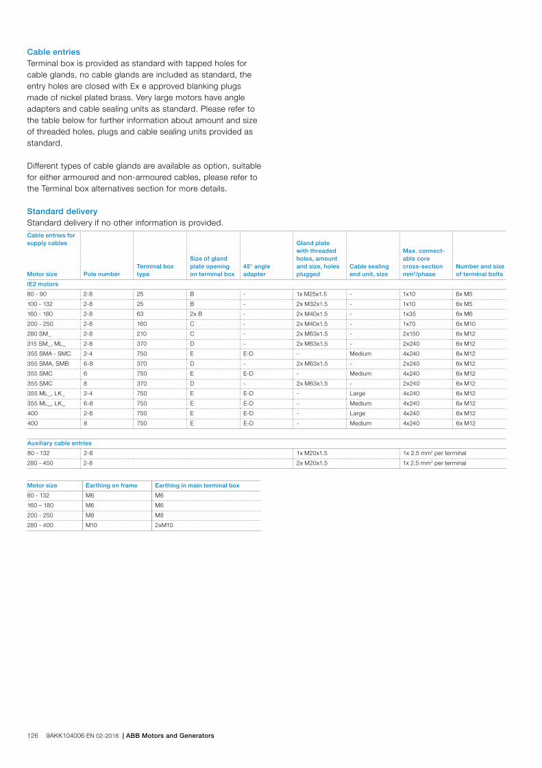
Standard deliveryStandard delivery if no other information is provided.
Motor size Earthing on frame Earthing in main terminal box
80 - 132 M6 M6
160 – 180 M6 M6
200 - 250 M8 M8
280 - 400 M10 2xM10
Cable entries for supply cables
Motor size Pole numberTerminal box type
Size of gland plate opening on terminal box
45° angle adapter
Gland plate with threaded holes, amount and size, holes plugged
Cable sealing end unit, size
Max. connect- able core cross-section mm2/phase
Number and size of terminal bolts
IE2 motors
80 - 90 2-8 25 B - 1x M25x1.5 - 1x10 6x M5
100 - 132 2-8 25 B - 2x M32x1.5 - 1x10 6x M5
160 - 180 2-8 63 2x B - 2x M40x1.5 - 1x35 6x M6
200 - 250 2-8 160 C - 2x M40x1.5 - 1x70 6x M10
280 SM_ 2-8 210 C - 2x M63x1.5 - 2x150 6x M12
315 SM_, ML_ 2-8 370 D - 2x M63x1.5 - 2x240 6x M12
355 SMA - SMC 2-4 750 E E-D - Medium 4x240 6x M12
355 SMA, SMB 6-8 370 D - 2x M63x1.5 - 2x240 6x M12
355 SMC 6 750 E E-D - Medium 4x240 6x M12
355 SMC 8 370 D - 2x M63x1.5 - 2x240 6x M12
355 ML_, LK_ 2-4 750 E E-D - Large 4x240 6x M12
355 ML_, LK_ 6-8 750 E E-D - Medium 4x240 6x M12
400 2-6 750 E E-D - Large 4x240 6x M12
400 8 750 E E-D - Medium 4x240 6x M12
Auxiliary cable entries
80 - 132 2-8 1x M20x1.5 1x 2.5 mm2 per terminal
280 - 450 2-8 2x M20x1.5 1x 2.5 mm2 per terminal
Cable entriesTerminal box is provided as standard with tapped holes for cable glands, no cable glands are included as standard, the entry holes are closed with Ex e approved blanking plugs made of nickel plated brass. Very large motors have angle adapters and cable sealing units as standard. Please refer to the table below for further information about amount and size of threaded holes, plugs and cable sealing units provided as standard.
Different types of cable glands are available as option, suitable for either armoured and non-armoured cables, please refer to the Terminal box alternatives section for more details.
126 9AKK104006 EN 02-2016 | ABB Motors and Generators
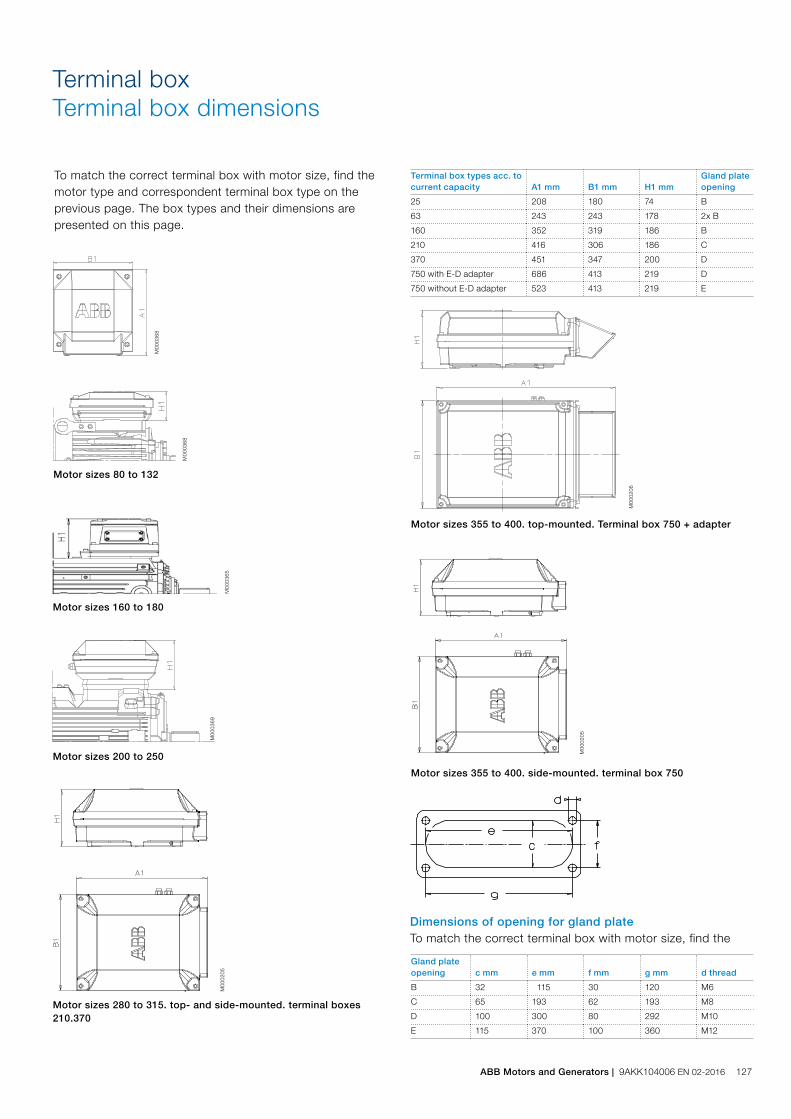
Terminal box types acc. to current capacity A1 mm B1 mm H1 mm
Gland plate opening
25 208 180 74 B
63 243 243 178 2x B
160 352 319 186 B
210 416 306 186 C
370 451 347 200 D
750 with E-D adapter 686 413 219 D
750 without E-D adapter 523 413 219 E
Terminal boxTerminal box dimensions
To match the correct terminal box with motor size, find the motor type and correspondent terminal box type on the previous page. The box types and their dimensions are presented on this page.
Gland plate opening c mm e mm f mm g mm d thread
B 32 115 30 120 M6
C 65 193 62 193 M8
D 100 300 80 292 M10
E 115 370 100 360 M12
Dimensions of opening for gland plateTo match the correct terminal box with motor size, find the
Motor sizes 80 to 132
Motor sizes 280 to 315. top- and side-mounted. terminal boxes 210.370
Motor sizes 355 to 400. side-mounted. terminal box 750
Motor sizes 160 to 180
Motor sizes 355 to 400. top-mounted. Terminal box 750 + adapter
M00
0205
M00
0365
M00
0369
M00
0368
M00
0368
Motor sizes 200 to 250 M00
0205
M00
0206
ABB Motors and Generators | 9AKK104006 EN 02-2016 127

The pictures below show standard terminal boxes and the corresponding terminal boards for various motor sizes.
Terminal boxTerminal boxes and boards
Cable glands are not delivered as standard.
Fig 5. Terminal box for motor sizes 355 to 400, with adapter and cable sealing end unit.
Fig 4. Terminal box for motor sizes 280 to 315 with connection flange and cable glands.
M00
0423
M00
0424
Fig 1. Terminal box for motor sizes 80 to132
Fig 2. Terminal box for motor sizes 160 to 180
Fig 3. Terminal box for motor sizes 200 to 250
Fig 10. Terminal board for motor sizes 280 to 315.
Fig 11. Terminal board for motor sizes 355 to 400.
M00
0428
M00
0427
M00
0720
M00
0719
Fig 7. Terminal board for motor sizes 80 to 132
Fig 8. Terminal board for motor sizes 160 to 180
Fig 9. Terminal board for motor sizes 200 to 250
M00
0721
M
0007
18
M00
0723
M00
0722
Fig 12. Terminal board for motor size 450.
M00
0429
Fig 6. Terminal box for motor sizes 450, with adapter and cable sealing end unit.
M00
0425
Terminal boxes
Terminal boards
128 9AKK104006 EN 02-2016 | ABB Motors and Generators

Optional cable termination partsThere is a broad selection of cable termination accessories available to allow a safe and reliable termination of one or several supply cables. The most common options are explained in this chapter.
How to order − Check first that the terminal box itself allows mounting
of the desired cable and cores (refer to table showing standard delivery for each motor size). If very large cable are used might it be necessary to use a larger terminal box and larger terminal board than standard
− Select the right cable gland(s) or cable sealing end unit based on the diameter of the cables(s) and suitability for cable type
− Select appropriate adapter or flange to allow mounting on opening in terminal box
− Note that turning the terminal box might be prevented by use of some adapters.
Terminal boxTerminal box alternatives
Ordering example
Motor and supply cables 145kW, 4-pole, 400V 50Hz, IE2. Cables needed: 1 pcs outer diameter 42mm steel wire armoured cable, single cross section 120 mm2. Cables coming from below. Gland plate material steel.
Motor M3HP 315MLA 4, B3
Adapter (to allow entry of cables coming from below)
Variant code 293 (adaptor D-D)
Cable glands Ex d / Ex e suitable for armoured cables (an M50 gland will suit this cable)
Variant code 734 (specify cable dimensions)
Gland plate made of steel drilled and tapped with 1 pcs M50 hole (non-std size)
Variant code 554 (1 pcs M50 x 1.5 threaded hole to be specified)
Adapter M00
0430
M00
0431
M00
0432
M00
0433
M00
0434
M00
0434
Variant code 292 293 294 295 296 444
Suited for motor sizes 280 315, 355 315 LKC,355 - 450
315 LKC,355 - 450
315 LKC,355 - 450
315 LKC,355 - 450
Opening to terminal box C D E E E E
Flange or opening for end unit
C D D 2 x D 3 x D 2 x E
Material Steel Steel Steel Steel Steel Steel
Notes Included in type 750 terminal box when 750 is the standard size.
Included in type 1200 terminal box when 1200 is the standard size.
Only possible on type 1200 terminal box
Only possible on type 1200 terminal box
Optional adaptersTo allow easy termination of cables entering the terminal box from above or below, is an angle adapter recommended. These are available for motor sizes 280 and above and can also be used to allow mounting of several cable sealing end units or gland plates. For exact suitability on a certain motor size, refer to the “size of gland plate opening on terminal box” column in section Standard terminal box.
ABB Motors and Generators | 9AKK104006 EN 02-2016 129

Gland plate size Maximum amount and size of threaded holes
B 2 x M40
C 2 x M63
D 2 x M90 or 3 x M75
E 2 x M90 or 4 x M75
Cable glandsThe motors are delivered as standard with plugged cable entries or cable sealing units as described in the previous section. There is a broad selection of different type of cable glands available which are suitable for different types of cable and outer diameter ranges.
Size of threaded opening for cable gland
Cable gland(s) nickel plated brass, Ex e, for non armoured cable, variant code 230 or 731
EMC Cable gland(s) nickel plated brass, Ex e, for non armoured cable, variant code 704
Cable gland Ex d IIC / Ex e for armoured cable with double sealing, variant code 734
Metric (std) Cable outer diameter, mm Cable outer diameter, mm Cable outer diameter, mm Inner sheath diameter, mm
M16 x 1.5 4-8 4-8 7-12 4.5-8
M20 x 1.5 4-12 4-12 10-16 6-10
M25 x 1.5 - - 13.5-19 10-14
M25 x 1.5 *) 10-18 10-18 19-25 14-18
M32 x 1.5 14-24 14-24 25-30 18-23
M40 x 1.5 22-32 22-32 30-36 23-28
M50 x 1.5 - - 36-40 28-32
M50 x 1.5 *) 26-35 26-35 40-46 32-37
M63 x 1.5 - - 46-53 37-43
M63 x 1.5 *) 35-45 35-45 53-60 43-50
M75 x 1.5 46-62 46-62 58-70 48-60
M90 x 1.5 - 78-90 68-80
M100 x 1.5 - 88-100 78-90
*) = High capacity version, delivered as standard with the variant code
Threaded openings for cable glands with NPT thread (variant code 730)The motors are delivered as standard with openings for cable glands with metric threads as listed in the section describing the standard terminal box. If glands with NPT threads will be used must variant code 730 be ordered. If nothing else is stated on the ordered will the sizes in tables below be delivered.
Motor frame size Main cable entries NPT plug
80-112 1 x ¾” -
132 2 x ¾” 1 x ¾”
160-180 2 x 1 ¼” 1 x 1 ¼”
200-250 2 x 1 ½” 1 x 1 ½”
280 2 x 2” 1 x 2”
315-450 2 x 3” 1 x 3”
Motor frame size Cable entries for auxiliaries NPT plug
80-112 2 x ¾” 2 x ¾”
132 1 x ¾” 1 x ¾”
160-450 2 x ¾” 2 x ¾”
Gland plates with threaded openings for cable glands of nonstandard sizeIf the standard size of threaded openings for cable glands does not suit the gland size and cable that will be used can openings of nonstandard size also be delivered, either by fitting a reducers to make the openings smaller or by increasing the amount or size of holes. The maximum possible size and amount for each gland plate size is listed below. Threaded openings of non-standard size can be ordered using variant codes 554 and 555.
Gland plates of non-standard materialThe standard material used in gland plates is steel. Gland plates made of aluminum or stainless steel are optional, either with cable glands or blind without threaded holes. Please refer to the variant code section for more information.
130 9AKK104006 EN 02-2016 | ABB Motors and Generators
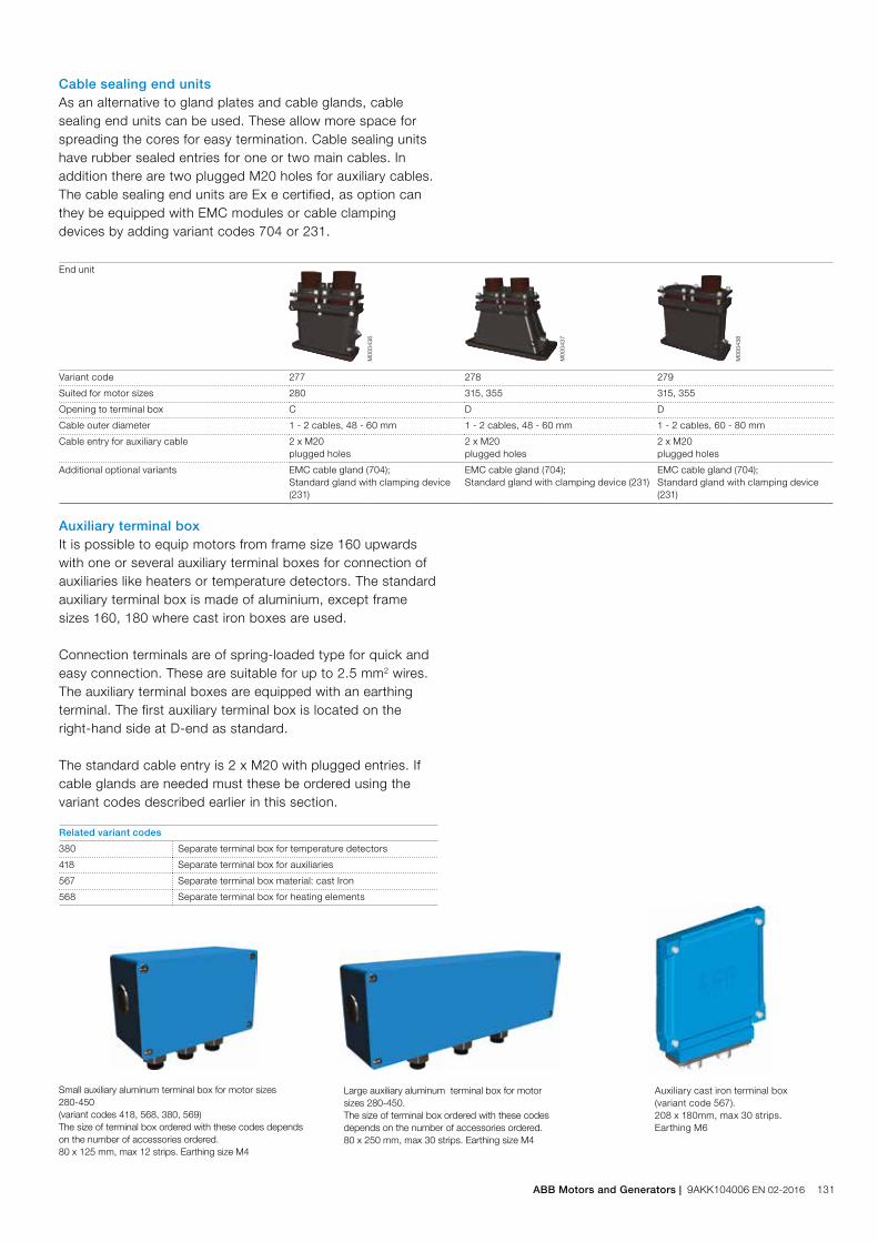
Cable sealing end unitsAs an alternative to gland plates and cable glands, cable sealing end units can be used. These allow more space for spreading the cores for easy termination. Cable sealing units have rubber sealed entries for one or two main cables. In addition there are two plugged M20 holes for auxiliary cables. The cable sealing end units are Ex e certified, as option can they be equipped with EMC modules or cable clamping devices by adding variant codes 704 or 231.
End unit
M00
0436
M00
0437
M00
0438
Variant code 277 278 279
Suited for motor sizes 280 315, 355 315, 355
Opening to terminal box C D D
Cable outer diameter 1 - 2 cables, 48 - 60 mm 1 - 2 cables, 48 - 60 mm 1 - 2 cables, 60 - 80 mm
Cable entry for auxiliary cable 2 x M20 plugged holes
2 x M20 plugged holes
2 x M20 plugged holes
Additional optional variants EMC cable gland (704);Standard gland with clamping device (231)
EMC cable gland (704);Standard gland with clamping device (231)
EMC cable gland (704);Standard gland with clamping device (231)
Auxiliary terminal boxIt is possible to equip motors from frame size 160 upwards with one or several auxiliary terminal boxes for connection of auxiliaries like heaters or temperature detectors. The standard auxiliary terminal box is made of aluminium, except frame sizes 160, 180 where cast iron boxes are used.
Connection terminals are of spring-loaded type for quick and easy connection. These are suitable for up to 2.5 mm2 wires. The auxiliary terminal boxes are equipped with an earthing terminal. The first auxiliary terminal box is located on the right-hand side at D-end as standard.
The standard cable entry is 2 x M20 with plugged entries. If cable glands are needed must these be ordered using the variant codes described earlier in this section.
Related variant codes
380 Separate terminal box for temperature detectors
418 Separate terminal box for auxiliaries
567 Separate terminal box material: cast Iron
568 Separate terminal box for heating elements
Small auxiliary aluminum terminal box for motor sizes 280-450 (variant codes 418, 568, 380, 569)The size of terminal box ordered with these codes depends on the number of accessories ordered.80 x 125 mm, max 12 strips. Earthing size M4
Large auxiliary aluminum terminal box for motor sizes 280-450.The size of terminal box ordered with these codes depends on the number of accessories ordered.80 x 250 mm, max 30 strips. Earthing size M4
Auxiliary cast iron terminal box (variant code 567). 208 x 180mm, max 30 strips. Earthing M6
ABB Motors and Generators | 9AKK104006 EN 02-2016 131

Dimension drawingsIncreased safety cast iron motors
Tolerances:
A, B ± 0.8
D, DA ISO k6 < Ø 50mm
ISO m6 > Ø 50mm
F, FA ISO h9
H -0.5
N ISO j6
C, CA ± 0.8
In all dimension drawings: The tables give the main dimensions in mm. For detailed drawings please see our web-pages ‘www.abb.com/motors&generators’ or contact ABB.
GA
FD
Foot-mounted motor IM 1001, IM B3
Flange-mounted motor IM 3001, IM B5 Sizes 225 to 400
Protective roof, variant code 005
M00
0269
M00
0198
M00
0199
M00
0200
IM 1001. IM B3 AND IM 3001. IM B5 IM 1001. IM B3 IM 3001. IM B5 Protective roof
Motorsize
Dpoles
GApoles
Fpoles
Epoles
L maxpoles O 1) A B B’ C HD K H M N P S DS
LSpoles
2 4-8 2 4-8 2 4-8 2 4-8 2 4-8 2 4-8
80 19 19 21.5 21.5 6 6 40 40 340 340 20 125 100 125 50 241 10 80 165 130 200 12 160 360 360
90 24 24 27 27 8 8 50 50 405 405 20 140 100 125 56 266 10 90 165 130 200 12 180 430 430
100 28 28 31 31 8 8 60 60 480 480 25 160 140 – 63 286 12 100 215 180 250 14.5 195 505 505
112 28 28 31 31 8 8 60 60 480 480 25 190 140 – 70 301 12 112 215 180 250 14.5 195 505 505
132 38 38 41 41 10 10 80 80 560 560 30 216 140 178 89 346 12 132 265 230 300 14.5 260 590 590
160 42 42 45 45 12 12 110 110 808 808 45 254 210 254 108 499 14.5 160 300 250 350 18.5 328 852 852
180 48 48 51.5 51.5 14 14 110 110 826 826 50 279 241 279 121 539 14.5 180 300 250 350 18.5 359 876 876
200 55 55 59 59 16 16 110 110 774 774 70 318 267 305 133 536 18.5 200 350 300 400 18.5 414 844 844
225 55 60 59 64 16 18 110 140 841 871 80 356 286 311 149 583 18.5 225 400 350 450 18.5 462 921 951
250 60 65 64 69 18 18 140 140 875 875 90 406 311 349 168 646 24 250 500 450 550 18.5 506 965 965
280 65 75 69 79.5 18 20 140 140 1088 1088 100 457 368 419 190 759 24 280 500 450 550 18 555 1190 1190
315 SM_ 65 80 69 85 18 22 140 170 1174 1204 115 508 406 457 216 852 30 315 600 550 660 23 624 1290 1320
315 ML_ 65 90 69 95 18 25 140 170 1285 1315 115 508 457 508 216 852 30 315 600 550 660 23 624 1401 1431
355 SM_ 70 100 62.5 90 20 28 140 210 1409 1479 130 610 500 560 254 958 35 355 740 680 800 23 720 1476 1546
355 ML_ 70 100 62.5 90 20 28 140 210 1514 1584 130 610 560 630 254 958 35 355 740 680 800 23 720 1528 1703
355 LK_ 70 100 62.5 90 20 28 140 210 1764 1834 130 610 710 900 254 958 35 355 740 680 800 23 720 1633 1703
400 L_ 80 110 85 126 22 28 170 210 1851 1891 150 710 900 1000 224 1045 35 400 940 880 1000 28 810 1860 1900
400 LK_ 80 100 85 106 22 28 170 210 1851 1891 150 686 710 800 280 1045 35 400 740 680 800 24 810 1860 1900
Sizes 80 to 200
Flange size Variant code
Flange dimension Motor size 80-132
P M N S 80 90 100 112 132
FT100 258 120 100 80 M6 S M NA NA NA
FT115 260 140 115 95 M8 M S NA NA NA
FT130 229 160 130 110 M8 M M S S NA
FT165 236 200 165 130 M10 M M M M S
FT215 246 250 215 180 M12 NA NA M M M
FT265 256 300 265 230 M12 NA NA NA NA M
FF100 257 120 100 80 Ø7 M M NA NA NA
FF115 259 140 115 95 Ø10 M M NA NA NA
FF130 228 160 130 110 Ø10 M M M M NA
FF165 235 200 165 130 Ø12 S S M M M
FF215 245 250 215 180 Ø14.5 NA NA S S M
FF265 255 300 265 230 Ø14.5 NA NA NA NA S
IM 3601, IM B14 - Available flange alternatives; see also variant codes.
S = Standard flange M = Modification NA = Not applicable
1) Required distance from fan cover air inlet to obstacle behind motor.
132 9AKK104006 EN 02-2016 | ABB Motors and Generators
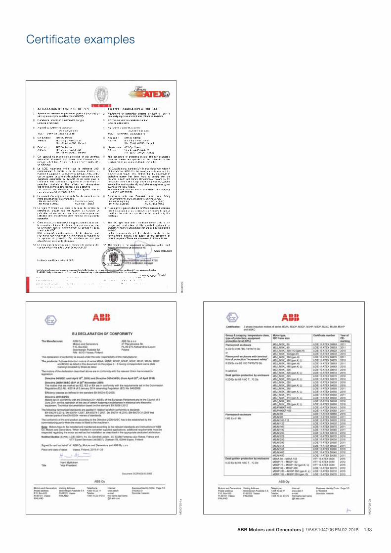
Certificate examples
M00
0728
M00
0725
-2a
M00
0725
-1a
ABB Motors and Generators | 9AKK104006 EN 02-2016 133
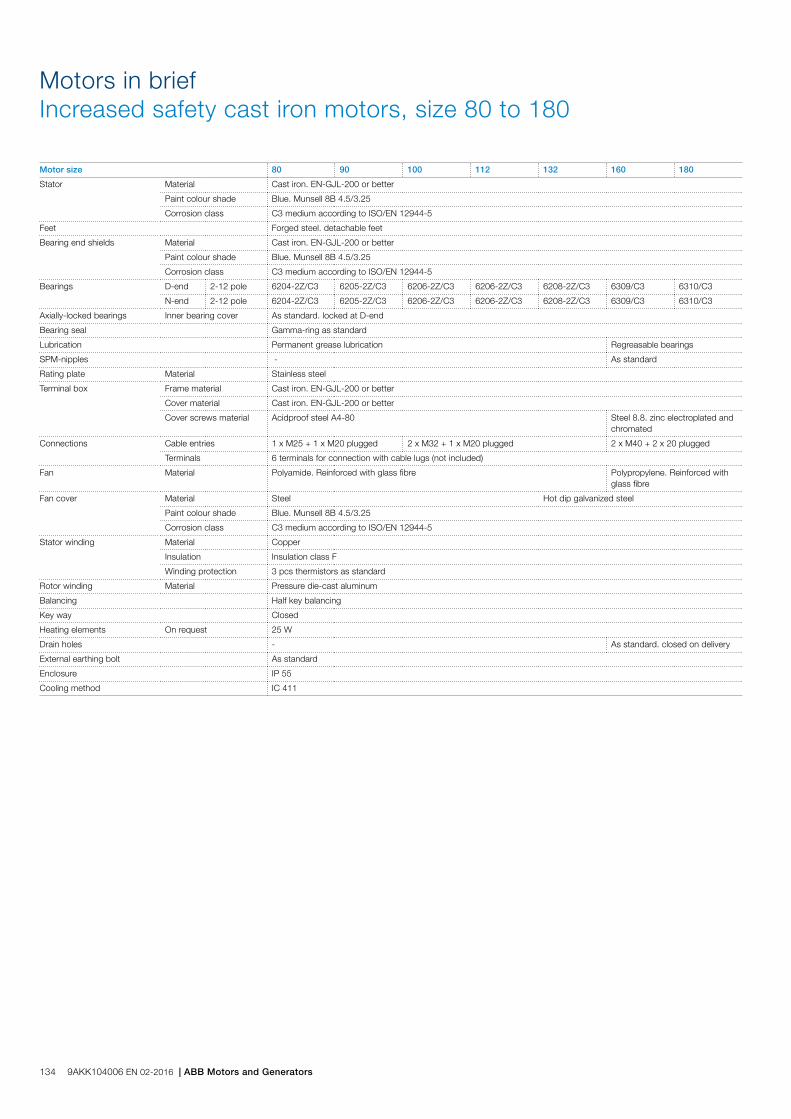
Motors in briefIncreased safety cast iron motors, size 80 to 180
Motor size 80 90 100 112 132 160 180
Stator Material Cast iron. EN-GJL-200 or better
Paint colour shade Blue. Munsell 8B 4.5/3.25
Corrosion class C3 medium according to ISO/EN 12944-5
Feet Forged steel. detachable feet
Bearing end shields Material Cast iron. EN-GJL-200 or better
Paint colour shade Blue. Munsell 8B 4.5/3.25
Corrosion class C3 medium according to ISO/EN 12944-5
Bearings D-end 2-12 pole 6204-2Z/C3 6205-2Z/C3 6206-2Z/C3 6206-2Z/C3 6208-2Z/C3 6309/C3 6310/C3
N-end 2-12 pole 6204-2Z/C3 6205-2Z/C3 6206-2Z/C3 6206-2Z/C3 6208-2Z/C3 6309/C3 6310/C3
Axially-locked bearings Inner bearing cover As standard. locked at D-end
Bearing seal Gamma-ring as standard
Lubrication Permanent grease lubrication Regreasable bearings
SPM-nipples - As standard
Rating plate Material Stainless steel
Terminal box Frame material Cast iron. EN-GJL-200 or better
Cover material Cast iron. EN-GJL-200 or better
Cover screws material Acidproof steel A4-80 Steel 8.8. zinc electroplated and chromated
Connections Cable entries 1 x M25 + 1 x M20 plugged 2 x M32 + 1 x M20 plugged 2 x M40 + 2 x 20 plugged
Terminals 6 terminals for connection with cable lugs (not included)
Fan Material Polyamide. Reinforced with glass fibre Polypropylene. Reinforced with glass fibre
Fan cover Material Steel Hot dip galvanized steel
Paint colour shade Blue. Munsell 8B 4.5/3.25
Corrosion class C3 medium according to ISO/EN 12944-5
Stator winding Material Copper
Insulation Insulation class F
Winding protection 3 pcs thermistors as standard
Rotor winding Material Pressure die-cast aluminum
Balancing Half key balancing
Key way Closed
Heating elements On request 25 W
Drain holes - As standard. closed on delivery
External earthing bolt As standard
Enclosure IP 55
Cooling method IC 411
134 9AKK104006 EN 02-2016 | ABB Motors and Generators

Motors in briefIncreased safety cast iron motors, sizes 200 to 400
Motor size 200 225 250 280 315 355 400
Stator Material Cast iron. EN-GJL-200 or better
Paint colour shade Blue. Munsell 8B 4.5/3.25
Corrosion class C3 medium according to ISO/EN 12944-5
Feet Cast iron. EN-GJL-200 or better. integrated with stator
Bearing end shields Material Cast iron. EN-GJL-200 or better
Paint colour shade Blue. Munsell 8B 4.5/3.25
Corrosion class C3 medium according to ISO/EN 12944-5
Bearings D-end 2-pole 6312M/C3 6313M/C3 6315M/C3 6316/C3 6316/C3 6316M/C3 6317M/C3
4-12 -pole 6312/C3 6313/C3 6315/C3 6316/C3 6319/C3 6322/C3 6324/C3
N-end 2-pole 6310M/C3 6312M/C3 6313M/C3 6316/C3 6316/C3 6316M/C3 6317M/C3
4-12 -pole 6310/C3 6312/C3 6313/C3 6316/C3 6316/C3 6316/C3 6319/C3
Axially-locked bearings Inner bearing cover As standard. locked at D-end
Bearing seal Gamma ring V-ring or labyrinth seal. refer to table on page 84
Lubrication Regreasable bearings
SPM-nipples As standard
Rating plate Material Stainless steel
Terminal box Frame material Cast iron. EN-GJL-200 or better
Cover material Cast iron. EN-GJL-200 or better
Cover screws material Steel 8.8. zinc electroplated and chromated
Connections Cable entries 2 x M40 + 2 x M20 plugged 2 x M63 + 2 x M20 plugged Refer to table on page 126
Terminals 6 terminals for connection with cable lugs (not included)
Fan Material Polypropylene. Reinforced with glass fibre Polypropylene reinforced with glass fibre or aluminum
Fan cover Material Hot dip galvanized steel
Paint colour shade Blue. Munsell 8B 4.5/3.25
Corrosion class C3 medium according to ISO/EN 12944-5
Stator winding Material Copper
Insulation Insulation class F
Winding protection 3 pcs thermistors as standard
Rotor winding Material Pressure die-cast aluminum
Balancing Half key balancing
Heating elements On request 25 W 60 W 120 W
Key way Closed Open
Drain holes As standard. open on delivery
External earthing bolt As standard
Enclosure IP 55
Cooling method IC 411
ABB Motors and Generators | 9AKK104006 EN 02-2016 135
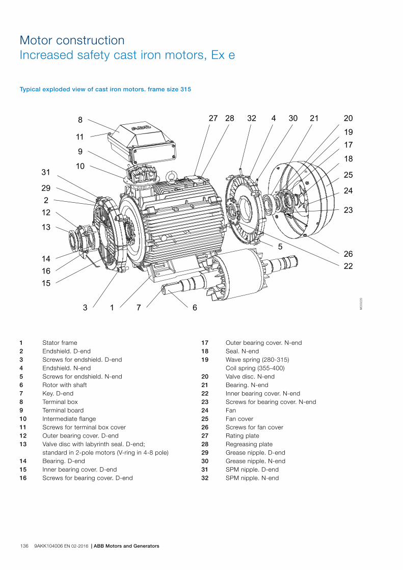
Motor constructionIncreased safety cast iron motors, Ex e
Typical exploded view of cast iron motors. frame size 315
1 Stator frame 2 Endshield. D-end 3 Screws for endshield. D-end 4 Endshield. N-end 5 Screws for endshield. N-end 6 Rotor with shaft 7 Key. D-end 8 Terminal box 9 Terminal board 10 Intermediate flange 11 Screws for terminal box cover 12 Outer bearing cover. D-end 13 Valve disc with labyrinth seal. D-end; standard in 2-pole motors (V-ring in 4-8 pole) 14 Bearing. D-end 15 Inner bearing cover. D-end 16 Screws for bearing cover. D-end
17 Outer bearing cover. N-end 18 Seal. N-end 19 Wave spring (280-315) Coil spring (355-400) 20 Valve disc. N-end 21 Bearing. N-end 22 Inner bearing cover. N-end 23 Screws for bearing cover. N-end 24 Fan 25 Fan cover 26 Screws for fan cover 27 Rating plate 28 Regreasing plate 29 Grease nipple. D-end 30 Grease nipple. N-end 31 SPM nipple. D-end 32 SPM nipple. N-end
M00
0220
136 9AKK104006 EN 02-2016 | ABB Motors and Generators

Non-sparking cast iron motors Ex nATotally enclosed squirrel cage three phase low voltage motors, Sizes 71 to 450, 0.25 to 1000 kW
Ordering information 134
Rating plates 139
Technical data 140
IE2 3000 r/min motors 140
IE2 1500 r/min motors 141
IE2 1000 r/min motors 142
IE2 750 r/min motors 143
IE3 3000 r/min motors 144
IE3 1500 r/min motors 145
IE3 1000 r/min motors 146
IE3 750 r/min motors 147
Variant codes 148
Mechanical design 153
Motor frame and drain holes 153
Heating elements 154
Bearings 155
Terminal box 165
Dimension drawings 174
Certificate examples 175
Cast iron motors in brief 176
Motor construction 178
ABB Motors and Generators | 9AKK104006 EN 06-2014 137

When placing an order, specify motor type, size and product code according to the following example.
Positions 1 - 4
3GGP:
3GAA:
Totally enclosed fan cooled squirrel cage motor with cast iron frame, non-sparkingTotally enclosed fan cooled squirrel cage motor with aluminum frame, non-sparking
Positions 5 and 6
IEC-frame
06 63
07 71
08: 80
09: 90
10: 100
11: 112
13: 132
16: 160
18: 180
20: 200
22: 225
25: 250
28: 280
31: 315
35: 355
40: 400
45 450
Position 7
Speed (Pole pairs)
1: 2 poles
2: 4 poles
3: 6 poles
4: 8 poles
5: 10 poles
Positions 8 to 10
Serial number
Position 11
- (Dash)
Position 12
Mounting arrangement
A: Foot-mounted, top-mounted terminal box
R: Foot-mounted, terminal box RHS seen from D-end
L: Foot-mounted, terminal box LHS seen from D-end
Ordering information
B: Flange-mounted, large flange
C: Flange-mounted, small flange (sizes 71 to 112)
H: Foot- and flange-mounted, terminal box top-mounted
J: Foot- and flange-mounted, small flange with tapped holes
S: Foot- and flange-mounted, terminal box RHS seen from D-end
T: Foot- and flange-mounted, terminal box LHS seen from D-end
V Flange-mounted, special flange
F: Foot- and flange-mounted. Special flange
Position 13
Voltage and frequency
Single-speed motors
B: 380 VΔ 50 Hz
D: 400 VΔ, 415 VΔ, 690 VY 50 Hz
E: 500 VΔ 50 Hz
F: 500 VY 50 Hz
S: 230 VΔ, 400 VY, 415 VY 50 Hz
T: 660 VΔ 50 Hz
U: 690 VΔ 50 Hz
X: Other rated voltage, connection or frequency, 690 V maximum
Position 14
Generation code
G, H...
The product code must be, if needed, followed by variant codes.
Explanation of the product codeMotor type Motor size Product code Mounting arrangement code,
Voltage and frequency code,Generation code
Variant codes
M3GP 160MLA 3GGP 161 410 - ADD 002, etc. 1 2 3 4 5 6 7 8 9 10 11 12 13 14
Example
Motor type M3GP 160 MLA
Pole number 2
Mounting arrangement (IM-code) IM B3 (IM 1001)
Rated output 11 kW
Product code 3GGP161410-ADD
Variant codes if needed
138 9AKK104006 EN 06-2014 | ABB Catalog

Rating plates
The rating plates are in table form giving values for speed, current and power factor for cast iron motors: 400V-415V-690V as standard. For aluminum motors there are one or two voltages in use; 230V-400V depending on the frame size. Other voltage and frequency combinations are possible and can be ordered with variant codes 002 or 209. Please see Variant code section.
The following information will be shown on the motor rating plate:
− Lowest nominal efficiency at 100 %, 75 % and 50 % rated load
− Efficiency level − Year of manufacture − Type of protection − Apparatus group − Temperature class − Identification number of the certification body − Certificate number : for cast iron motors both ATEX and
IECEx are stamped on the rating plate as standard. For aluminum motors self certification.
Plates
ABB Motors and Generators | 9AKK104006 EN 06-2014 139

Output kW Motor type Product code
Speed r/min
Efficiency Power factor cos j
Current Torque Moment of inertiaJ = 1/4 GD2 kgm2
Weight kg
Sound pressure level LPA dB
Full load 100%
3/4 load 75%
1/2 load 50%
IN A
Is IN
TN Nm
Tl TN
Tb TN
3000 r/min = 2-poles 400 V 50 Hz CENELEC-design
0.37 M3GP 71MA 2 3GGP071321-••B 2768 74.8 75.4 72.4 0.78 0.89 4.5 1.27 2.2 2.3 0.00039 11 58
0.55 M3GP 71MB 2 3GGP071322-••B 2813 77.8 78.3 76.0 0.79 1.29 4.3 1.86 2.4 2.5 0.00051 11 56
0.75 M3GP 80MB 2 3GGP081322-••B 2895 80.6 79.6 75.6 0.74 1.8 7.7 2.4 4.2 4.2 0.001 16 57
1.1 M3GP 80MC 2 3GGP081323-••B 2870 81.8 81.7 79.0 0.80 2.48 7.5 3.6 3.7 4.6 0.0012 18 60
1.5 M3GP 90SLB 2 3GGP091322-••B 2900 82.2 82.9 81.3 0.89 2.94 7.5 4.9 2.5 2.6 0.00254 24 69
2.2 M3GP 90SLC 2 3GGP091323-••B 2885 84.7 86.8 85.7 0.88 4.2 6.8 7.2 1.9 2.5 0.0028 25 64
3 M3GP 100LB 2 3GGP101322-••B 2925 85.2 84.9 82.7 0.87 5.75 9.1 9.7 3.1 3.5 0.0053 36 68
4 M3GP 112MB 2 3GGP111322-••B 2895 86.1 87.0 86.6 0.89 7.52 8.7 13.08 3.3 3.5 0.00575 37 70
5.5 M3GP 132SMB 2 3GGP131322-••B 2865 87.7 88.4 87.7 0.86 10 7.0 18.3 2.6 2.7 0.0128 68 70
7.5 M3GP 132SMC 2 3GGP131324-••B 2890 88.2 88.5 87.5 0.88 13.7 8.3 24.7 2.6 3.6 0.0136 70 70
11 M3GP 160MLA 2 3GGP161410-••D 2931 90.1 90.4 89.3 0.89 20.2 6.7 35.81 2.5 3.2 0.043 139 71
15 M3GP 160MLB 2 3GGP161420-••D 2929 91.2 91.7 90.8 0.89 27 7.2 48.9 2.9 3.4 0.052 149 71
18.5 M3GP 160MLC 2 3GGP161430-••D 2934 91.6 92.4 92.3 0.90 32.4 7.4 60.3 3.1 3.5 0.062 159 69
22 M3GP 180MLA 2 3GGP181410-••D 2938 91.7 92.3 91.8 0.90 39.1 7.0 71.4 2.5 3.2 0.089 199 69
30 M3GP 200MLA 2 3GGP201410-••D 2956 93.2 93.6 93.0 0.88 52.7 7.4 96.9 3.0 3.2 0.15 275 74
37 M3GP 200MLC 2 3GGP201430-••D 2954 93.6 94.0 93.4 0.89 64.7 7.5 119.9 2.8 3.2 0.19 304 75
45 M3GP 225SMB 2 3GGP221220-••D 2968 93.8 93.9 93.0 0.87 78.8 7.2 144 2.7 3.0 0.26 357 76
55 M3GP 250SMA 2 3GGP251210-••D 2975 94.3 94.2 93.2 0.89 95.1 7.8 176 2.4 3.1 0.49 445 75
75 3) M3GP 280SMA 2 3GGP281210-••G 2977 94.3 93.8 92.2 0.88 131 7.6 240 2.1 3.0 0.8 625 77
90 3) M3GP 280SMB 2 3GGP281220-••G 2976 94.6 94.7 93.8 0.89 154 7.4 288 2.1 2.9 0.9 665 77
110 3) M3GP 315SMA 2 3GGP311210-••G 2982 94.9 94.4 92.9 0.86 197 7.4 352 2.2 3.2 1.2 880 78
132 3) M3GP 315SMB 2 3GGP311220-••G 2982 95.1 94.8 93.6 0.88 227 7.4 422 2.2 3.0 1.4 940 78
160 3) M3GP 315SMC 2 3GGP311230-••G 2981 95.4 95.2 94.2 0.89 271 7.5 512 2.3 3.0 1.7 1025 78
200 3) M3GP 315MLA 2 3GGP311410-••G 2980 95.7 95.7 94.9 0.90 335 7.7 640 2.6 3.0 2.1 1190 78
250 3) M3GP 355SMA 2 3GGP351210-••G 2984 95.7 95.5 94.5 0.89 423 7.7 800 2.1 3.3 3.0 1600 83
315 3) M3GP 355SMB 2 3GGP351220-••G 2980 95.7 95.6 95.0 0.89 531 7.0 1009 2.1 3.0 3.4 1680 83
355 3) M3GP 355SMC 2 3GGP351230-••G 2984 95.7 95.7 94.9 0.88 603 7.2 1136 2.2 3.0 3.6 1750 83
400 3) M3GP 355MLA 2 3GGP351410-••G 2982 96.9 96.6 95.9 0.88 677 7.1 1280 2.3 2.9 4.1 2000 83
450 3) M3GP 355MLB 2 3GGP351420-••G 2983 97.1 97.0 96.4 0.90 743 7.9 1440 2.2 2.9 4.3 2080 83
500 3) M3GP 355LKA 2 3GGP351810-••G 2982 96.9 96.9 96.5 0.90 827 7.5 1601 2.0 3.9 4.8 2320 83
560 3) M3GP 355LKB 2 3GGP351820-••G 2983 97.0 97.0 96.5 0.90 925 8.0 1792 2.2 4.1 5.2 2460 83
560 2)) M3GP 400LA 2 3GGP401510-••G 2988 97.2 97.2 96.6 0.89 934 7.8 1789 2.5 3.7 7.9 2950 82
560 2)) M3GP 400LKA 2 3GGP401810-••G 2988 97.2 97.2 96.6 0.89 934 7.8 1789 2.5 3.7 7.9 2950 82
630 2) M3GP 400LB 2 3GGP401520-••G 2987 97.4 97.2 96.7 0.89 1049 7.6 2014 2.6 3.7 8.2 3050 82
630 2) M3GP 400LKB 2 3GGP401820-••G 2987 97.4 97.2 96.7 0.89 1049 7.6 2014 2.6 3.7 8.2 3050 82
710 2) M3GP 400LC 2 3GGP401530-••G 2987 97.5 97.4 96.9 0.89 1178 7.2 2270 2.6 3.4 9.3 3300 82
710 2) M3GP 400LKC 2 3GGP401830-••G 2987 97.5 97.4 96.9 0.89 1178 7.2 2270 2.6 3.4 9.3 3300 82
3000 r/min = 2-poles 400 V 50 Hz High-output design
22 1) M3GP 160MLD 2 3GGP161440-••D 2929 91.2 91.9 91.4 0.90 38.3 7.5 71.7 3.1 3.3 0.07 166 77
30 M3GP 180MLB 2 3GGP181420-••D 2943 92.5 93.2 92.6 0.90 52.2 7.1 97.23 2.3 3.2 0.13 236 78
37 M3GP 180MLC 2 3GGP181430-••D 2950 92.8 93.1 92.8 0.90 64.9 8.1 119.9 3.3 3.7 0.13 237 77
45 M3GP 200MLE 2 3GGP201450-••D 2944 93.3 93.6 93.0 0.88 79.1 7.3 145 2.9 3.1 0.22 312 79
55 M3GP 225SMC 2 3GGP221230-••D 2965 93.9 94.2 93.5 0.88 95.8 7.1 177 2.6 3.0 0.29 377 80
67 M3GP 225SMD 2 3GGP221240-••D 2966 93.9 93.9 93.0 0.86 120 7.4 215 2.8 3.2 0.31 388 78
75 M3GP 250SMB 2 3GGP251220-••D 2969 93.8 93.9 93.2 0.89 129 7.9 241 2.6 3.1 0.57 487 80
90 M3GP 250SMC 2 3GGP251230-••D 2965 94.4 94.5 93.9 0.89 153 7.7 289 2.5 3.0 0.59 500 80
110 3) M3GP 280SMC 2 3GGP281230-••G 2978 95.1 95.1 94.5 0.90 186 7.9 352 2.4 3.0 1.15 725 77
132 3) M3GP 280MLA 2 3GGP281410-••G 2977 95.3 95.3 94.8 0.90 221 7.5 423 2.5 3.0 1.4 840 81
160 M3GP 280MLB 2 3GGP281420-••G 2976 95.5 95.7 95.3 0.91 265 7.6 513 2.8 3.0 1.55 890 81
IP 55 - IC 411 - Insulation class F, temperature rise class BIE2 efficiency class according to IEC 60034-30-1; 2014
Technical data for Ex nA IIC T3 Gc Non-sparking IE2 cast iron motors
1) Efficiency class IE12) Unidirectional fan construction as standard. Direction of rotation must be stated when ordering, see variant codes 044 and 0453) -3dB(A) sound pressure level reduction with unidirectional fan construction. Direction of rotation must be stated when ordering, see variant codes 044 and 045
140 9AKK104006 EN 06-2014 | ABB Catalog

1) Efficiency class IE12) Temperature rise class F
IP 55 - IC 411 - Insulation class F, temperature rise class BIE2 efficiency class according to IEC 60034-30-1; 2014
Technical data for Ex nA IIC T3 Gc Non-sparking IE2 cast iron motors
Output kW Motor type Product code
Speed r/min
Efficiency Power factor cos j
Current Torque Moment of inertiaJ = 1/4 GD2 kgm2
Weight kg
Sound pressure level LPA dB
Full load 100%
3/4 load 75%
1/2 load 50%
IN A
Is IN
TN Nm
Tl TN
Tb TN
1500 r/min = 4-poles 400 V 50 Hz CENELEC-design
0.25 1) M3GP 71MA 4 3GGP072321-••B 1365 68.3 70.7 69.6 0.81 0.64 3.5 1.74 1.9 2.0 0.00074 10 45
0.37 1) M3GP 71MB 4 3GGP072322-••B 1380 72.4 74.5 74.7 0.83 0.87 4.6 2.5 1.6 2.1 0.00088 11 45
0.55 1) M3GP 80MA 4 3GGP082321-••B 1415 70.0 69.2 64.7 0.73 1.44 5.6 3.7 2.0 2.8 0.00144 15 45
0.75 M3GP 80MD 4 3GGP082324-••B 1430 81.0 81.0 78.2 0.73 1.82 5.3 5 2.7 3.2 0.00205 17 50
1.1 M3GP 90SLB 4 3GGP092322-••B 1435 83.6 84.1 82.4 0.80 2.36 6.5 7.3 2.4 3.4 0.0044 25 50
1.5 M3GP 90SLD 4 3GGP092325-••B 1430 84.3 85.1 83.9 0.82 3 6.3 10 2.7 3.4 0.0053 27 56
2.2 M3GP 100LC 4 3GGP102323-••B 1450 85.9 85.1 83.4 0.78 4.6 7.7 14.5 2.7 4.1 0.00948 36 56
3 M3GP 100LD 4 3GGP102324-••B 1450 86.8 86.9 85.3 0.79 6.1 7.7 19.8 2.9 3.4 0.011 38 58
4 M3GP 112MB 4 3GGP112322-••B 1440 86.8 87.7 87.4 0.82 7.94 7.0 26.5 2.5 2.9 0.0125 44 59
5.5 M3GP 132SMB 4 3GGP132322-••B 1460 89.0 89.8 88.9 0.80 10.8 6.7 36 2.2 3.2 0.0328 70 67
7.5 M3GP 132SMC 4 3GGP132323-••B 1450 89.3 90.1 90.0 0.81 14.5 7.2 49.4 2.5 3.5 0.0366 73 64
11 M3GP 160MLC 4 3GGP162430-••D 1470 91.2 91.3 90.0 0.82 21.5 8.0 71.5 3.3 3.8 0.096 160 62
15 M3GP 160MLE 4 3GGP162450-••D 1467 92.0 92.3 91.8 0.84 28.5 8.0 97.7 3.3 3.2 0.13 183 61
18.5 M3GP 180MLA 4 3GGP182410-••D 1474 91.6 92.1 91.5 0.83 35.7 7.2 119.9 2.6 3.1 0.19 213 62
22 M3GP 180MLB 4 3GGP182420-••D 1474 92.2 92.5 91.9 0.82 42 7.7 142.3 2.8 3.4 0.23 232 62
30 M3GP 200MLB 4 3GGP202420-••D 1471 92.5 93.2 93.1 0.84 55 7.4 194 3.0 2.8 0.34 306 61
37 M3GP 225SMB 4 3GGP222220-••D 1480 93.6 93.9 93.4 0.85 69 7.6 239 3.2 2.9 0.42 347 67
45 M3GP 225SMC 4 3GGP222230-••D 1477 94.1 94.4 94.3 0.86 78.4 7.6 291 3.2 2.7 0.49 379 67
55 M3GP 250SMA 4 3GGP252210-••D 1479 94.3 94.3 93.6 0.84 100 7.2 355 2.5 3.1 0.72 436 66
75 M3GP 280SMA 4 3GGP282210-••G 1484 94.5 94.7 94.4 0.85 134 6.9 482 2.5 2.8 1.25 625 68
90 M3GP 280SMB 4 3GGP282220-••G 1483 94.7 95.0 94.5 0.85 160 7.2 579 2.5 2.7 1.5 665 68
110 M3GP 315SMA 4 3GGP312210-••G 1487 95.1 95.1 94.3 0.86 194 7.2 706 2.3 2.8 2.3 900 70
132 M3GP 315SMB 4 3GGP312220-••G 1487 95.4 95.4 94.7 0.86 232 7.1 847 2.3 2.7 2.6 960 70
160 M3GP 315SMC 4 3GGP312230-••G 1487 95.3 95.3 94.8 0.85 284 7.2 1027 2.4 2.9 2.9 1000 70
200 M3GP 315MLA 4 3GGP312410-••G 1486 95.6 95.8 95.5 0.86 351 7.2 1285 2.5 2.9 3.5 1160 70
250 M3GP 355SMA 4 3GGP352210-••G 1488 95.9 96.0 95.5 0.85 442 7.1 1604 2.3 2.7 5.9 1610 74
315 M3GP 355SMB 4 3GGP352220-••G 1488 95.9 96.2 95.8 0.86 550 7.3 2021 2.3 2.8 6.9 1780 74
350 4) M3GP 355SMC 4 3GGP352230-••G 1487 95.9 95.9 95.7 0.86 612 6.9 2247 2.4 2.7 7.2 1820 78
400 4) M3GP 355MLA 4 3GGP352410-••G 1489 96.3 96.3 95.9 0.85 705 6.8 2565 2.3 2.6 8.4 2140 78
450 4) M3GP 355MLB 4 3GGP352420-••G 1490 96.8 96.8 96.3 0.86 784 6.9 2884 2.3 2.9 8.4 2140 78
500 M3GP 355LKA 4 3GGP352810-••G 1490 97.0 97.0 96.5 0.86 865 6.8 3204 2.0 3.0 10 2500 78
560 3) M3GP 400LA 4 3GGP402510-••G 1491 96.8 96.8 96.3 0.85 982 7.4 3586 2.4 2.8 15 3200 78
560 3) M3GP 400LKA 4 3GGP402810-••G 1491 96.8 96.8 96.3 0.85 982 7.4 3586 2.4 2.8 15 3200 78
630 4) M3GP 400LB 4 3GGP402520-••G 1491 97.0 97.0 96.5 0.87 1077 7.6 4034 2.2 2.9 16 3300 78
630 4) M3GP 400LKB 4 3GGP402820-••G 1491 97.0 97.0 96.5 0.87 1077 7.6 4034 2.2 2.9 16 3300 78
710 3) M3GP 400LC 4 3GGP402530-••G 1491 97.1 97.1 96.7 0.86 1227 7.6 4547 2.4 3.0 17 3400 78
710 3) M3GP 400LKC 4 3GGP402830-••G 1491 97.1 97.1 96.7 0.86 1227 7.6 4547 2.4 3.0 17 3400 78
800 M3GP 450LA 4 3GGP452510-••G 1491 96.9 96.9 96.4 0.86 1396 7.0 5121 1.3 2.8 23 4050 85
900 M3GP 450LB 4 3GGP452520-••G 1492 97.1 97.0 96.5 0.86 1573 7.0 5761 1.3 2.8 25 4350 85
1000 2) M3GP 450LC 4 3GGP452530-••G 1491 97.2 97.2 96.7 0.86 1724 6.8 6404 1.3 2.7 30 4700 85
1500 r/min = 4-poles 400 V 50 Hz High-output design
18.5 M3GP 160MLF 4 3GGP162460-••H 2929 91.2 91.9 91.4 0.90 38.3 7.5 71.7 3.1 3.3 0.07 166 77
22 1) M3GP 160MLG 4 3GGP162470-••H 2943 92.5 93.2 92.6 0.90 52.2 7.1 97.23 2.3 3.2 0.13 236 78
30 1) M3GP 180MLC 4 3GGP182430-••H 2950 92.8 93.1 92.8 0.90 64.9 8.1 119.9 3.3 3.7 0.13 237 77
37 M3GP 200MLC 4 3GGP202430-••G 2944 93.3 93.6 93.0 0.88 79.1 7.3 145 2.9 3.1 0.22 312 79
55 M3GP 225SMD 4 3GGP222240-••D 2965 93.9 94.2 93.5 0.88 95.8 7.1 177 2.6 3.0 0.29 377 80
60 1) M3GP 225SME 4 3GGP222250-••D 2966 93.9 93.9 93.0 0.86 120 7.4 215 2.8 3.2 0.31 388 78
75 M3GP 250SMB 4 3GGP252220-••D 2969 93.8 93.9 93.2 0.89 129 7.9 241 2.6 3.1 0.57 487 80
86 1) M3GP 250SMC 4 3GGP252230-••D 2965 94.4 94.5 93.9 0.89 153 7.7 289 2.5 3.0 0.59 500 80
110 M3GP 280SMC 4 3GGP282230-••G 2978 95.1 95.1 94.5 0.90 186 7.9 352 2.4 3.0 1.15 725 77
132 M3GP 280MLA 4 3GGP282410-••G 2977 95.3 95.3 94.8 0.90 221 7.5 423 2.5 3.0 1.4 840 81
3) Temp. Rise class F, For 400-415 V 50 Hz (380 V 50 Hz voltage code B)4) For 400-415 V 50 Hz (380 V 50 Hz voltage code B)
ABB Motors and Generators | 9AKK104006 EN 06-2014 141
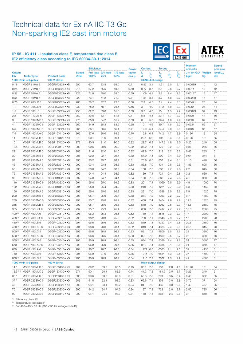
IP 55 - IC 411 - Insulation class F, temperature rise class BIE2 efficiency class according to IEC 60034-30-1; 2014
Technical data for Ex nA IIC T3 Gc Non-sparking IE2 cast iron motors
Output kW Motor type Product code
Speed r/min
Efficiency Power factor cos j
Current Torque Moment of inertiaJ = 1/4 GD2 kgm2
Weight kg
Sound pressure level LPA dB
Full load 100%
3/4 load 75%
1/2 load 50%
IN A
Is IN
TN Nm
Tl TN
Tb TN
1000 r/min = 6-poles 400 V 50 Hz CENELEC-design
0.18 M3GP 71MA 6 3GGP073321-••B 900 63.7 63.8 59.0 0.71 0.57 3.1 1.91 2.0 2.1 0.00089 10 42
0.25 M3GP 71MB 6 3GGP073322-••B 915 67.2 65.5 59.5 0.69 0.77 3.7 2.6 2.6 2.7 0.0011 12 42
0.37 M3GP 80MA 6 3GGP083321-••B 925 71.0 70.0 65.0 0.69 1.09 4.1 3.8 2.4 2.5 0.00187 15 47
0.55 M3GP 80MB 6 3GGP083322-••B 920 73.1 74.2 71.9 0.71 1.51 3.8 5.7 1.8 2.2 0.00239 17 47
0.75 M3GP 90SLC 6 3GGP093323-••B 960 78.7 77.2 72.5 0.58 2.3 4.5 7.4 2.4 3.1 0.00491 25 44
1.1 M3GP 90SLE 6 3GGP093324-••B 930 78.2 78.7 76.5 0.66 3 4.0 11.2 1.9 2.3 0.0054 28 44
1.5 M3GP 100L 6 3GGP103322-••B 950 82.2 83.0 81.6 0.69 3.7 4.3 15 1.5 2.7 0.00873 37 49
2.2 M3GP 112MB 6 3GGP113322-••B 950 82.5 83.7 81.6 0.71 5.5 4.4 22.1 1.7 2.3 0.0125 44 66
3 M3GP 132SMB 6 3GGP133321-••B 975 85.3 84.2 81.2 0.63 8 5.5 29.4 1.8 2.9 0.0334 69 57
4 M3GP 132SMC 6 3GGP133322-••B 960 84.9 85.3 83.9 0.68 10 4.6 39.7 1.5 2.2 0.0334 69 57
5.5 M3GP 132SMF 6 3GGP133324-••B 965 86.1 86.5 85.4 0.71 12.9 5.1 54.4 2.0 2.3 0.0487 86 57
7.5 M3GP 160MLA 6 3GGP163410-••D 965 87.6 88.6 88.3 0.78 15.8 6.4 74.2 1.7 2.9 0.126 181 65
11 M3GP 160MLB 6 3GGP163420-••D 972 90.1 91.0 90.4 0.81 22.1 6.9 108 2.4 3.5 0.126 181 65
15 M3GP 180MLB 6 3GGP183420-••D 973 90.5 91.0 90.5 0.82 29.7 6.8 147.3 1.8 3.0 0.25 240 58
18.5 M3GP 200MLA 6 3GGP203410-••D 983 90.5 90.9 90.2 0.82 36.2 7.1 179 3.2 3.1 0.37 266 66
22 M3GP 200MLB 6 3GGP203420-••D 983 91.6 92.0 91.5 0.82 42.8 7.5 213 3.2 3.2 0.43 283 61
30 M3GP 225SMB 6 3GGP223220-••D 985 92.2 92.7 92.4 0.82 57.9 7.4 290 3.4 3.0 0.64 344 61
37 M3GP 250SMA 6 3GGP253210-••D 990 93.2 93.7 93.1 0.81 70.6 6.5 357 2.4 3.1 1.16 440 66
45 M3GP 280SMA 6 3GGP283210-••G 990 93.4 93.8 93.5 0.83 83.8 7.0 434 2.5 2.5 1.85 605 66
55 M3GP 280SMB 6 3GGP283220-••G 990 93.8 94.2 93.9 0.84 100 7.0 530 2.7 2.6 2.2 645 66
75 M3GP 315SMA 6 3GGP313210-••G 992 94.4 94.4 93.5 0.82 139 7.4 721 2.4 2.8 3.2 830 70
90 M3GP 315SMB 6 3GGP313220-••G 992 94.8 94.7 94.1 0.84 166 7.5 866 2.4 2.8 4.1 930 70
110 M3GP 315SMC 6 3GGP313230-••G 991 95.0 95.0 94.6 0.83 201 7.4 1059 2.5 2.9 4.9 1000 70
132 M3GP 315MLA 6 3GGP313410-••G 991 95.3 95.4 94.9 0.83 240 7.5 1271 2.7 3.0 5.8 1150 68
160 M3GP 355SMA 6 3GGP353210-••G 993 95.4 95.6 95.2 0.83 291 7.0 1538 2.0 2.6 7.9 1520 75
200 M3GP 355SMB 6 3GGP353220-••G 993 95.7 95.9 95.7 0.83 364 7.2 1923 2.2 2.7 9.7 1680 75
250 M3GP 355SMC 6 3GGP353230-••G 993 95.7 95.8 95.4 0.82 460 7.4 2404 2.6 2.9 11.3 1820 75
315 M3GP 355MLB 6 3GGP353420-••G 992 95.7 96.0 95.5 0.83 570 7.0 3032 2.5 2.7 13.5 2180 75
355 M3GP 355LKA 6 3GGP353810-••G 992 95.7 95.9 95.4 0.81 658 7.6 3417 2.7 2.9 15.5 2500 75
400 3) M3GP 400LA 6 3GGP403510-••G 993 96.2 96.3 95.8 0.82 730 7.1 3846 2.3 2.7 17 2900 76
400 3) M3GP 400LKA 6 3GGP403810-••G 993 96.2 96.3 95.8 0.82 730 7.1 3846 2.3 2.7 17 2900 76
450 3) M3GP 400LB 6 3GGP403520-••G 994 96.6 96.6 96.1 0.82 819 7.4 4323 2.4 2.8 20.5 3150 76
450 3) M3GP 400LKB 6 3GGP403820-••G 994 96.6 96.6 96.1 0.82 819 7.4 4323 2.4 2.8 20.5 3150 76
500 3) M3GP 400LC 6 3GGP403530-••G 993 96.6 96.5 96.1 0.83 891 7.2 4809 2.5 2.7 22 3300 76
500 3) M3GP 400LKC 6 3GGP403830-••G 993 96.6 96.5 96.1 0.83 891 7.2 4809 2.5 2.7 22 3300 76
560 3) M3GP 400LD 6 3GGP403540-••G 993 96.9 96.9 96.4 0.85 984 7.4 5386 2.4 2.8 24 3400 77
560 M3GP 400LKD 6 3GGP403840-••G 993 96.9 96.9 96.4 0.85 984 7.4 5386 2.4 2.8 24 3400 77
630 M3GP 450LA 6 3GGP453510-••G 994 96.7 96.7 96.3 0.84 1127 6.5 6053 1.1 2.5 31 4150 81
710 M3GP 450LB 6 3GGP453520-••G 995 96.9 97.0 96.5 0.85 1244 7.0 6814 1.3 2.5 37 4500 81
800 2) M3GP 450LC 6 3GGP453530-••G 995 96.9 96.9 96.4 0.84 1415 7.2 7677 1.3 2.7 41 4800 81
1000 r/min = 6-poles 400 V 50 Hz High-output design
14 1) M3GP 160MLC 6 3GGP163430-••D 969 89.2 89.5 88.5 0.75 30.1 7.5 138 2.8 4.0 0.126 181 64
18.5 1) 2) M3GP 180MLC 6 3GGP183430-••D 971 90.1 90.1 88.5 0.74 41.2 7.3 181.2 2.5 3.7 0.25 240 61
30 1) M3GP 200MLC 6 3GGP203430-••D 983 90.6 90.8 89.6 0.81 59.3 7.5 291 3.5 3.4 0.49 302 65
37 1) M3GP 225SMC 6 3GGP223230-••D 983 91.8 92.1 92.2 0.83 69.6 7.1 359 3.0 2.8 0.75 371 64
45 M3GP 250SMB 6 3GGP253220-••D 986 93.1 93.4 93.2 0.84 84 7.2 435 3.3 2.8 1.49 487 65
75 M3GP 280SMC 6 3GGP283230-••G 990 94.2 94.7 94.5 0.84 137 7.3 723 2.8 2.7 2.85 725 66
90 M3GP 280MLA 6 3GGP283410-••G 990 94.1 94.3 93.7 0.81 170 7.1 868 2.4 2.5 3.1 840 70
1) Efficiency class IE12) Temperature rise class F3) For 400-415 V 50 Hz (380 V 50 Hz voltage code B)
142 9AKK104006 EN 06-2014 | ABB Catalog

IP 55 - IC 411 - Insulation class F, temperature rise class BIE2 efficiency class according to IEC 60034-30-1; 2014
Technical data for Ex nA IIC T3 Gc Non-sparking IE2 cast iron motors
Output kW Motor type Product code
Speed r/min
Efficiency Power factor cos j
Current Torque Moment of inertiaJ = 1/4 GD2 kgm2
Weight kg
Sound pressure level LPA dB
Full load 100%
3/4 load 75%
1/2 load 50%
IN A
Is IN
TN Nm
Tl TN
Tb TN
750 r/min = 8-poles 400 V 50 Hz CENELEC-design
0.09 M3GP 71MA 8 3GGP074101-••B 660 49.4 46.3 39.6 0.6 0.44 2.7 1.3 2 2.5 0.00089 11 40
0.12 M3GP 71MB 8 3GGP074102-••B 670 51.4 47.5 39.9 0.56 0.6 2.7 1.7 2 2.5 0.0011 12 43
0.18 M3GP 80MA 8 3GGP084101-••B 700 57.4 53.7 46.1 0.62 0.78 3.2 2.5 2.1 2.8 0.00187 15 45
0.25 M3GP 80MB 8 3GGP084102-••B 680 61.5 61.3 53.5 0.65 0.94 3.1 3.5 1.9 2.6 0.00239 17 50
0.37 M3GP 90SLB 8 3GGP094102-••B 705 66.3 64 57 0.54 1.47 2.8 5 1.9 2.5 0.00444 24 50
0.55 M3GP 90SLC 8 3GGP094103-••B 655 61.8 65.6 65.2 0.67 1.92 2.6 8 1.4 1.9 0.00491 25 53
0.75 M3GP 100LA 8 3GGP104101-••B 710 74 72.3 67.1 0.61 2.48 3.7 10.1 1.8 2.6 0.0072 30 46
1.1 M3GP 100LB 8 3GGP104102-••B 695 76 76.4 74.5 0.66 3.12 3.6 15.1 1.6 2.3 0.00871 30 53
1.5 M3GP 112M 8 3GGP114101-••B 690 74.4 75.9 74.1 0.74 4.11 3.5 20.9 1.9 2.6 0.0106 39 55
2.2 M3GP 132SMA 8 3GGP134101-••B 715 79.7 79.5 77.1 0.66 6.51 4.7 29.2 1.6 2.8 0.0334 70 56
3 1) M3GP 132SMB 8 3GGP134102-••B 715 79.9 79.7 76.6 0.64 8.5 4.7 39.7 1.7 2.8 0.04 75 58
4 M3GP 160MLA 8 3GGP164410-••D 722 83.3 84.7 84.2 0.7 10.3 4.7 52.9 1.6 2.6 0.133 181 59
5.5 M3GP 160MLB 8 3GGP164420-••D 723 86.8 87.2 86 0.71 13.5 5.8 72.7 1.9 3.1 0.133 182 53
7.5 3) M3GP 160MLC 8 3GGP164430-••H 718 82 84 84 0.7 19.3 5.7 99.8 2.1 2.9 0.133 245 55
11 M3GP 180MLB 8 3GGP184420-••H 723 88.3 89.2 88.7 0.72 25.5 5.6 145 2 3 0.245 292 63
15 M3GP 200MLA 8 3GGP204410-••G 734 89.9 90.4 89.5 0.79 30.6 6.9 195 2.4 3.2 0.45 280 56
18.5 M3GP 225SMA 8 3GGP224210-••D 734 90 90.7 90.2 0.74 39.2 6.1 240 2.2 3 0.61 326 55
22 M3GP 225SMB 8 3GGP224220-••D 732 90.6 91.4 91.2 0.81 45.3 6.5 287 1.9 2.9 0.68 343 56
30 M3GP 250SMA 8 3GGP254210-••D 735 91.6 91 90.5 0.78 60.7 6.7 389 2 2.9 1.25 440 56
37 M3GP 280SMA 8 3GGP284210-••G 741 91.7 92 91.2 0.79 72.6 7.3 476 1.7 3 1.85 605 65
45 M3GP 280SMB 8 3GGP284220-••G 741 92.1 92.3 91.7 0.78 89.2 7.6 579 1.8 3.1 2.2 645 65
55 M3GP 315SMA 8 3GGP314210-••G 742 92.4 93 92.4 0.79 106 7.1 707 1.6 2.7 3.2 830 62
75 M3GP 315SMB 8 3GGP314220-••G 741 93 93.2 93 0.82 146 7.1 966 1.7 2.7 4.1 930 62
90 M3GP 315SMC 8 3GGP314230-••G 741 93.3 93.7 93.3 0.82 170 7.4 1159 1.8 2.7 4.9 1000 64
110 M3GP 315MLA 8 3GGP314410-••G 740 93.6 93.9 94 0.83 211 7.3 1419 1.8 2.7 5.8 1150 72
132 M3GP 355SMA 8 3GGP354210-••G 744 93.9 93.8 93.3 0.8 256 7.5 1694 1.5 2.6 7.9 1520 69
160 M3GP 355SMB 8 3GGP354220-••G 744 94.3 94.3 93.8 0.77 293 7.6 1926 1.6 2.6 9.7 1680 69
200 M3GP 355SMC 8 3GGP354230-••G 742 94.5 95 94.8 0.79 385 7.4 2576 1.6 2.6 11.3 1820 69
250 4) M3GP 355MLB 8 3GGP354420-••G 743 95.4 95.5 95 0.8 476 7.5 3213 1.6 2.7 13.5 2180 72
315 4) M3GP 400LA 8 3GGP404510-••G 744 96.1 96 95.6 0.81 592 7 4043 1.2 2.6 17 2900 71
315 4) M3GP 400LKA 8 3GGP404810-••G 744 96.1 96 95.6 0.81 592 7 4043 1.2 2.6 17 2900 71
355 4) M3GP 400LB 8 3GGP404520-••G 743 96.2 96.3 96.1 0.83 641 6.8 4562 1.2 2.5 21 3200 71
355 4) M3GP 400LKB 8 3GGP404820-••G 743 96.2 96.3 96.1 0.83 641 6.8 4562 1.2 2.5 21 3200 71
400 4) M3GP 400LC 8 3GGP404530-••G 744 96.3 96.4 96.1 0.82 735 7.4 5134 1.3 2.7 24 3400 71
400 4) M3GP 400LKC 8 3GGP404830-••G 744 96.3 96.4 96.1 0.82 735 7.4 5134 1.3 2.7 24 3400 71
450 M3GP 450LA 8 3GGP454510-••G 744 96.2 96.5 96.2 0.83 813 6 5775 1 2.5 26 3750 80
500 M3GP 450LB 8 3GGP454520-••G 744 96.3 96.4 96.2 0.83 902 6.4 6417 1 2.6 29 4000 80
560 M3GP 450LC 8 3GGP454530-••G 744 96.4 96.5 96.1 0.82 1038 7 7188 1.2 2.9 35 4350 80
630 2) M3GP 450LD 8 3GGP454540-••G 745 96.6 96.7 96.2 0.81 1162 7.6 8075 1.3 3.2 41 4800 80
750 r/min = 8-poles 400 V 50 Hz High-output design
18.5 M3GP 200MLB 8 3GGP204420-••G 734 89.2 89.8 88.8 0.8 37.1 6.9 240 2.2 3.2 0.54 300 57
30 M3GP 225SMC 8 3GGP224230-••D 731 90.7 91.6 91.6 0.78 61.2 6.3 391 2.3 3 0.75 369 59
37 M3GP 250SMB 8 3GGP254220-••D 737 92.2 92.9 92.5 0.79 73 7.5 479 2.3 3.4 1.52 487 59
55 M3GP 280SMC 8 3GGP284230-••G 741 93.4 93.7 93.6 0.8 107 7.9 708 1.9 3.1 2.85 725 65
1) Efficiency class IE12) Temperature rise class F3) IE0, Temperature rise class F4) For 400-415 V 50 Hz (380 V 50 Hz voltage code B)
ABB Motors and Generators | 9AKK104006 EN 06-2014 143
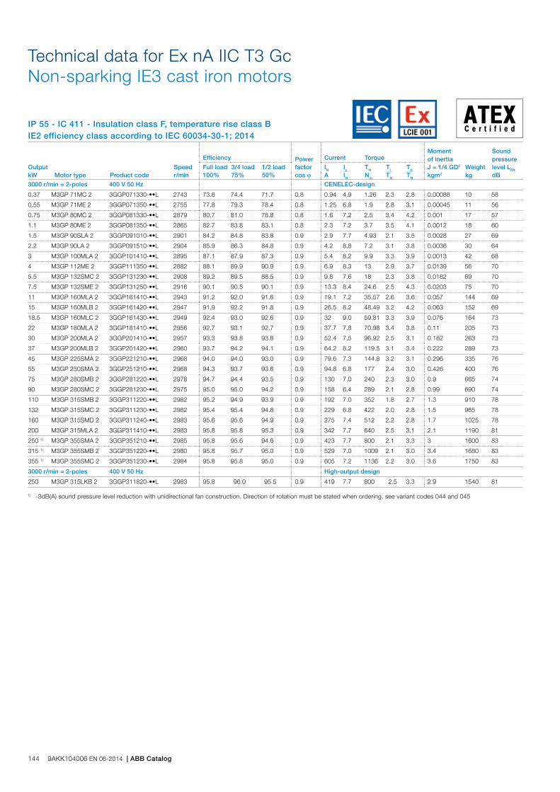
IP 55 - IC 411 - Insulation class F, temperature rise class BIE2 efficiency class according to IEC 60034-30-1; 2014
Technical data for Ex nA IIC T3 Gc Non-sparking IE3 cast iron motors
1) -3dB(A) sound pressure level reduction with unidirectional fan construction. Direction of rotation must be stated when ordering, see variant codes 044 and 045
Output kW Motor type Product code
Speed r/min
Efficiency Power factor cos j
Current Torque Moment of inertiaJ = 1/4 GD2 kgm2
Weight kg
Sound pressure level LPA dB
Full load 100%
3/4 load 75%
1/2 load 50%
IN A
Is IN
TN Nm
Tl TN
Tb TN
3000 r/min = 2-poles 400 V 50 Hz CENELEC-design
0.37 M3GP 71MC 2 3GGP071330-••L 2743 73.8 74.4 71.7 0.8 0.94 4.9 1.26 2.3 2.8 0.00088 10 58
0.55 M3GP 71ME 2 3GGP071350-••L 2755 77.8 79.3 78.4 0.8 1.25 6.8 1.9 2.8 3.1 0.00045 11 56
0.75 M3GP 80MC 2 3GGP081330-••L 2879 80.7 81.0 78.8 0.8 1.6 7.2 2.5 3.4 4.2 0.001 17 57
1.1 M3GP 80ME 2 3GGP081350-••L 2865 82.7 83.8 83.1 0.8 2.3 7.2 3.7 3.5 4.1 0.0012 18 60
1.5 M3GP 90SLA 2 3GGP091010-••L 2901 84.2 84.8 83.8 0.9 2.9 7.7 4.93 2.1 3.5 0.0028 27 69
2.2 M3GP 90LA 2 3GGP091510-••L 2904 85.9 86.3 84.8 0.9 4.2 8.8 7.2 3.1 3.8 0.0036 30 64
3 M3GP 100MLA 2 3GGP101410-••L 2895 87.1 87.9 87.3 0.9 5.4 8.2 9.9 3.3 3.9 0.0013 42 68
4 M3GP 112ME 2 3GGP111350-••L 2882 88.1 89.9 90.9 0.9 6.9 8.3 13 2.9 3.7 0.0139 56 70
5.5 M3GP 132SMC 2 3GGP131230-••L 2908 89.2 89.5 88.5 0.9 9.8 7.6 18 2.3 3.8 0.0182 69 70
7.5 M3GP 132SME 2 3GGP131250-••L 2916 90.1 90.5 90.1 0.9 13.3 8.4 24.6 2.5 4.3 0.0203 75 70
11 M3GP 160MLA 2 3GGP161410-••L 2943 91.2 92.0 91.6 0.9 19.1 7.2 35.57 2.6 3.6 0.057 144 69
15 M3GP 160MLB 2 3GGP161420-••L 2947 91.9 92.2 91.8 0.9 26.5 8.2 48.49 3.2 4.2 0.063 152 69
18.5 M3GP 160MLC 2 3GGP161430-••L 2949 92.4 93.0 92.6 0.9 32 9.0 59.81 3.3 3.9 0.076 164 73
22 M3GP 180MLA 2 3GGP181410-••L 2956 92.7 93.1 92.7 0.9 37.7 7.8 70.98 3.4 3.8 0.11 205 73
30 M3GP 200MLA 2 3GGP201410-••L 2957 93.3 93.8 93.6 0.9 52.4 7.5 96.92 2.5 3.1 0.182 263 73
37 M3GP 200MLB 2 3GGP201420-••L 2960 93.7 94.2 94.1 0.9 64.2 8.2 119.5 3.1 3.4 0.222 289 73
45 M3GP 225SMA 2 3GGP221210-••L 2968 94.0 94.0 93.0 0.9 79.6 7.3 144.8 3.2 3.1 0.296 335 76
55 M3GP 250SMA 2 3GGP251210-••L 2968 94.3 93.7 93.6 0.9 94.8 6.8 177 2.4 3.0 0.426 400 76
75 M3GP 280SMB 2 3GGP281220-••L 2978 94.7 94.4 93.5 0.9 130 7.0 240 2.3 3.0 0.9 665 74
90 M3GP 280SMC 2 3GGP281230-••L 2975 95.0 95.0 94.2 0.9 158 6.4 289 2.1 2.8 0.99 690 74
110 M3GP 315SMB 2 3GGP311220-••L 2982 95.2 94.9 93.9 0.9 192 7.0 352 1.8 2.7 1.3 910 78
132 M3GP 315SMC 2 3GGP311230-••L 2982 95.4 95.4 94.6 0.9 229 6.8 422 2.0 2.8 1.5 965 78
160 M3GP 315SMD 2 3GGP311240-••L 2983 95.6 95.6 94.9 0.9 275 7.4 512 2.2 2.8 1.7 1025 78
200 M3GP 315MLA 2 3GGP311410-••L 2983 95.8 95.8 95.3 0.9 342 7.7 640 2.5 3.1 2.1 1190 81
250 1) M3GP 355SMA 2 3GGP351210-••L 2985 95.8 95.6 94.6 0.9 423 7.7 800 2.1 3.3 3 1600 83
315 1) M3GP 355SMB 2 3GGP351220-••L 2980 95.8 95.7 95.0 0.9 529 7.0 1009 2.1 3.0 3.4 1680 83
355 1) M3GP 355SMC 2 3GGP351230-••L 2984 95.8 95.8 95.0 0.9 605 7.2 1136 2.2 3.0 3.6 1750 83
3000 r/min = 2-poles 400 V 50 Hz High-output design
250 M3GP 315LKB 2 3GGP311820-••L 2983 95.8 96.0 95.5 0.9 419 7.7 800 2.5 3.3 2.9 1540 81
144 9AKK104006 EN 06-2014 | ABB Catalog

IP 55 - IC 411 - Insulation class F, temperature rise class BIE2 efficiency class according to IEC 60034-30-1; 2014
Technical data for Ex nA IIC T3 Gc Non-sparking IE3 cast iron motors
Output kW Motor type Product code
Speed r/min
Efficiency Power factor cos j
Current Torque Moment of inertiaJ = 1/4 GD2 kgm2
Weight kg
Sound pressure level LPA dB
Full load 100%
3/4 load 75%
1/2 load 50%
IN A
Is IN
TN Nm
Tl TN
Tb TN
1500 r/min = 4-poles 400 V 50 Hz CENELEC-design
0.25 M3GP 71MD 4 3GGP072340-••L 1416 73.5 75.1 73.8 0.8 0.6 4.8 1.68 2.0 2.6 0.0009 11 45
0.37 M3GP 71MLE 4 3GGP072450-••L 1432 77.3 77.4 74.5 0.76 0.9 5.8 2.46 2.7 3.3 0.00122 15 45
0.55 M3GP 80MLC 4 3GGP082430-••L 1444 80.8 81.6 80.1 0.8 1.2 6.7 4 3.0 3.5 0.0028 20 45
0.75 M3GP 80MLE 4 3GGP082450-••L 1448 82.5 82.5 80.1 0.78 1.7 7.4 4.9 3.5 4.0 0.0033 22 50
1.1 M3GP 90LA 4 3GGP092510-••L 1443 84.1 84.6 83.5 0.76 2.4 5.2 7.26 3.4 4.2 0.0049 28 56
1.5 M3GP 90LB 4 3GGP092520-••L 1445 85.3 85.0 82.6 0.77 3.3 5.7 9.9 3.8 4.6 0.0067 32 56
2.2 M3GP 100LA 4 3GGP102510-••L 1448 86.7 89.0 86.1 0.81 4.5 7.5 14 2.3 3.6 0.0109 38 56
3 M3GP 100MLB 4 3GGP102420-••L 1444 87.7 88.4 87.6 0.81 6.1 7.0 19.8 3.3 4.1 0.0121 42 58
4 M3GP 112ME 4 3GGP112350-••L 1453 88.6 88.9 88.0 0.74 8.9 7.8 26 3.5 4.3 0.0188 52 59
5.5 M3GP 132SMB 4 3GGP132220-••L 1463 89.6 89.8 88.7 0.74 11.9 7.6 36 2.8 3.9 0.0295 68 70
7.5 M3GP 132SME 4 3GGP132250-••L 1462 90.4 90.8 90.2 0.76 15.7 7.9 49 3.0 4.0 0.0376 78 64
11 M3GP 160MLA 4 3GGP162410-••L 1477 91.4 91.8 91.1 0.82 21.1 7.6 71.27 2.6 3.3 0.11 160 61
15 M3GP 160MLB 4 3GGP162420-••L 1477 92.1 92.4 91.6 0.82 28.5 8.2 96.99 3.0 3.7 0.135 179 61
18.5 M3GP 180MLA 4 3GGP182410-••L 1481 92.6 93.2 92.9 0.83 34.9 7.2 119.3 2.8 3.0 0.219 215 60
22 M3GP 180MLB 4 3GGP182420-••L 1481 93.0 93.5 93.3 0.82 41.4 6.5 142 3.0 3.2 0.243 229 60
30 M3GP 200MLA 4 3GGP202410-••L 1483 93.6 93.8 93.4 0.84 54.8 7.5 193.2 2.7 3.2 0.385 292 63
37 M3GP 225SMA 4 3GGP222210-••L 1482 93.9 94.1 93.8 0.83 68.9 7.2 238.6 3.1 3.1 0.427 322 67
45 M3GP 225SMB 4 3GGP222220-••L 1482 94.2 94.4 94.0 0.84 82.3 8.0 290 3.2 3.5 0.525 357 66
55 M3GP 250SMA 4 3GGP252210-••L 1482 94.6 94.7 94.0 0.84 100 7.1 354.2 2.9 3.4 0.694 406 68
75 M3GP 280SMB 4 3GGP282220-••L 1485 95.0 95.2 94.8 0.86 133 6.4 483 2.3 2.8 1.38 645 75
90 M3GP 280SMC 4 3GGP282230-••L 1485 95.2 95.5 95.2 0.86 158 7.1 578 2.5 2.9 1.73 700 75
110 M3GP 315SMB 4 3GGP312220-••L 1489 95.4 95.5 94.9 0.84 198 7.0 705 2.1 3.0 2.43 930 71
132 M3GP 315SMC 4 3GGP312230-••L 1488 95.6 95.9 95.5 0.86 231 6.7 847 2.2 2.9 2.9 1000 71
160 M3GP 315SMD 4 3GGP312240-••L 1488 95.8 96.0 95.8 0.85 282 6.9 1026 2.2 3.0 3.2 1065 71
200 M3GP 315MLB 4 3GGP312420-••L 1487 96.0 96.4 96.4 0.86 351 6.8 1284 2.4 3.0 3.9 1220 74
250 M3GP 355SMA 4 3GGP352210-••L 1491 96.0 96.0 95.6 0.86 435 6.4 1601 2.1 2.9 5.9 1610 78
315 M3GP 355SMB 4 3GGP352220-••L 1491 96.0 96.1 95.7 0.85 550 7.3 2018 2.4 3.3 6.9 1780 78
355 M3GP 355SMC 4 3GGP352230-••L 1490 96.0 96.2 95.8 0.86 616 6.3 2273 2.3 2.8 7.2 1820 78
1500 r/min = 4-poles 400 V 50 Hz High-output design
250 M3GP 315LKA 4 3GGP312810-••L 1488 96.0 96.3 96.1 0.85 442 6.9 1604 2.5 3.2 4.4 1410 78
ABB Motors and Generators | 9AKK104006 EN 06-2014 145

IP 55 - IC 411 - Insulation class F, temperature rise class BIE2 efficiency class according to IEC 60034-30-1; 2014
Technical data for Ex nA IIC T3 Gc Non-sparking IE3 cast iron motors
Output kW Motor type Product code
Speed r/min
Efficiency Power factor cos j
Current Torque Moment of inertiaJ = 1/4 GD2 kgm2
Weight kg
Sound pressure level LPA dB
Full load 100%
3/4 load 75%
1/2 load 50%
IN A
Is IN
TN Nm
Tl TN
Tb TN
1000 r/min = 6-poles 400 V 50 Hz CENELEC-design
0.18 M3GP 71ME 6 3GGP073350-••L 887 63.9 64.3 59.8 0.74 0.57 3.2 1.9 1.9 2.2 0.0009 10 45
0.25 M3GP 80MB 6 3GGP083320-••L 942 68.6 67.0 61.7 0.61 0.82 4.8 2.5 2.7 2.9 0.0019 14 47
0.37 M3GP 80MC 6 3GGP083330-••L 936 73.5 73.9 71.1 0.67 1.06 5.1 3.8 2.6 2.9 0.0028 16 50
0.55 M3GP 80ME 6 3GGP083350-••L 933 77.2 77.9 75.9 0.68 1.52 5.0 5.6 2.7 2.9 0.0035 18 47
0.75 M3GP 90SLD 6 3GGP093040-••L 940 78.9 80.3 79.2 0.75 1.8 4.4 7.57 2.1 2.8 0.0056 29 44
1.1 M3GP 90LF 6 3GGP093560-••L 944 81.0 81.7 80.1 0.75 2.62 4.7 11.1 2.1 2.8 0.0068 33 44
1.5 M3GP 100MLB 6 3GGP103420-••L 960 82.5 82.5 80.1 0.68 3.8 5.4 14.9 2.7 3.4 0.012 41 49
2.2 M3GP 112MJ 6 3GGP113390-••L 962 84.3 85.5 84.7 0.68 5.3 4.2 21.8 1.4 2.3 0.0196 53 66
3 M3GP 132SMB 6 3GGP133220-••L 973 85.6 85.1 82.9 0.62 8 6.6 29.2 2.7 3.8 0.0355 75 57
4 M3GP 132SMF 6 3GGP133260-••L 971 86.8 86.5 84.7 0.62 10.7 6.6 39 2.7 3.8 0.0416 82 57
5.5 M3GP 132SMJ 6 3GGP133290-••L 966 88.0 89.1 88.9 0.73 12.3 4.2 54 1.7 2.7 0.0408 81 57
7.5 M3GP 160MLA 6 3GGP163410-••L 975 89.1 90.0 90.0 0.77 15.7 5.7 73.24 1.4 3.0 0.089 146 59
11 M3GP 160MLB 6 3GGP163420-••L 975 90.3 91.1 91.1 0.78 22.5 6.4 107.5 1.6 3.1 0.138 180 64
15 M3GP 180MLA 6 3GGP183410-••L 979 91.2 91.9 91.6 0.79 30.1 5.2 146.9 1.5 2.7 0.212 212 63
18.5 M3GP 200MLA 6 3GGP203410-••L 989 91.7 91.9 91.2 0.82 35.2 6.5 178.8 2.2 3.2 0.496 272 59
22 M3GP 200MLB 6 3GGP203420-••L 989 92.2 92.4 91.4 0.81 42.4 7.3 212.4 2.6 3.5 0.585 297 59
30 M3GP 225SMA 6 3GGP223210-••L 988 92.9 93.0 92.2 0.77 60.4 7.7 290.6 2.9 3.6 0.724 349 63
37 M3GP 250SMA 6 3GGP253210-••L 990 93.3 93.7 93.5 0.80 71.1 6.5 357 2.4 3.1 1.3 431 58
45 M3GP 280SMB 6 3GGP283220-••L 991 93.7 94.0 93.5 0.84 82 7.4 433 2.7 3.0 1.87 645 72
55 M3GP 280SMC 6 3GGP283230-••L 992 94.1 94.3 93.8 0.86 99 7.5 528 2.8 3.0 2.57 725 71
75 M3GP 315SMB 6 3GGP313220-••L 994 94.6 94.9 94.6 0.84 136 6.8 720 1.8 2.6 4.1 930 75
90 M3GP 315SMC 6 3GGP313230-••L 994 94.9 95.1 94.7 0.84 164 7.2 864 2.0 3.0 4.6 1000 76
110 M3GP 315SMD 6 3GGP313240-••L 994 95.1 95.3 95.0 0.83 200 7.3 1056 2.2 3.1 4.9 1040 75
132 M3GP 315MLB 6 3GGP313420-••L 995 95.4 95.5 95.1 0.82 242 7.3 1266 2.3 3.2 6.3 1200 72
160 M3GP 355SMA 6 3GGP353210-••L 993 95.6 95.8 95.6 0.82 292 6.7 1538 2.5 2.6 7.9 1520 75
200 M3GP 355SMB 6 3GGP353220-••L 993 95.8 96.2 96.1 0.82 365 6.7 1923 2.6 2.5 9.7 1680 75
250 M3GP 355SMC 6 3GGP353230-••L 993 95.8 96.1 95.8 0.81 465 7.7 2404 3.0 3.1 11.3 1820 75
315 M3GP 355MLB 6 3GGP353420-••L 993 95.8 96.1 96.0 0.83 571 6.8 3029 2.6 3.2 13.5 2180 76
355 M3GP 355LKA 6 3GGP353810-••L 993 95.8 96.0 95.9 0.81 653 7.5 3413 2.9 3.2 15.5 2500 76
1000 r/min = 6-poles 400 V 50 Hz High-output design
160 M3GP 315LKA 6 3GGP313810-••L 994 95.6 95.8 95.4 0.81 298 7.5 1535 2.2 3.1 7.3 1410 76
146 9AKK104006 EN 06-2014 | ABB Catalog

IP 55 - IC 411 - Insulation class F, temperature rise class BIE2 efficiency class according to IEC 60034-30-1; 2014
Technical data for Ex nA IIC T3 Gc Non-sparking IE3 cast iron motors
Output kW Motor type Product code
Speed r/min
Efficiency Power factor cos j
Current Torque Moment of inertiaJ = 1/4 GD2 kgm2
Weight kg
Sound pressure level LPA dB
Full load 100%
3/4 load 75%
1/2 load 50%
IN A
Is IN
TN Nm
Tl TN
Tb TN
1000 r/min = 6-poles 400 V 50 Hz CENELEC-design
0.18 M3GP 71ME 6 3GGP073350-••L 887 63.9 64.3 59.8 0.74 0.57 3.2 1.9 1.9 2.2 0.0009 10 45
0.25 M3GP 80MB 6 3GGP083320-••L 942 68.6 67.0 61.7 0.61 0.82 4.8 2.5 2.7 2.9 0.0019 14 47
0.37 M3GP 80MC 6 3GGP083330-••L 936 73.5 73.9 71.1 0.67 1.06 5.1 3.8 2.6 2.9 0.0028 16 50
0.55 M3GP 80ME 6 3GGP083350-••L 933 77.2 77.9 75.9 0.68 1.52 5.0 5.6 2.7 2.9 0.0035 18 47
0.75 M3GP 90SLD 6 3GGP093040-••L 940 78.9 80.3 79.2 0.75 1.8 4.4 7.57 2.1 2.8 0.0056 29 44
1.1 M3GP 90LF 6 3GGP093560-••L 944 81.0 81.7 80.1 0.75 2.62 4.7 11.1 2.1 2.8 0.0068 33 44
1.5 M3GP 100MLB 6 3GGP103420-••L 960 82.5 82.5 80.1 0.68 3.8 5.4 14.9 2.7 3.4 0.012 41 49
2.2 M3GP 112MJ 6 3GGP113390-••L 962 84.3 85.5 84.7 0.68 5.3 4.2 21.8 1.4 2.3 0.0196 53 66
3 M3GP 132SMB 6 3GGP133220-••L 973 85.6 85.1 82.9 0.62 8 6.6 29.2 2.7 3.8 0.0355 75 57
4 M3GP 132SMF 6 3GGP133260-••L 971 86.8 86.5 84.7 0.62 10.7 6.6 39 2.7 3.8 0.0416 82 57
5.5 M3GP 132SMJ 6 3GGP133290-••L 966 88.0 89.1 88.9 0.73 12.3 4.2 54 1.7 2.7 0.0408 81 57
7.5 M3GP 160MLA 6 3GGP163410-••L 975 89.1 90.0 90.0 0.77 15.7 5.7 73.24 1.4 3.0 0.089 146 59
11 M3GP 160MLB 6 3GGP163420-••L 975 90.3 91.1 91.1 0.78 22.5 6.4 107.5 1.6 3.1 0.138 180 64
15 M3GP 180MLA 6 3GGP183410-••L 979 91.2 91.9 91.6 0.79 30.1 5.2 146.9 1.5 2.7 0.212 212 63
18.5 M3GP 200MLA 6 3GGP203410-••L 989 91.7 91.9 91.2 0.82 35.2 6.5 178.8 2.2 3.2 0.496 272 59
22 M3GP 200MLB 6 3GGP203420-••L 989 92.2 92.4 91.4 0.81 42.4 7.3 212.4 2.6 3.5 0.585 297 59
30 M3GP 225SMA 6 3GGP223210-••L 988 92.9 93.0 92.2 0.77 60.4 7.7 290.6 2.9 3.6 0.724 349 63
37 M3GP 250SMA 6 3GGP253210-••L 990 93.3 93.7 93.5 0.80 71.1 6.5 357 2.4 3.1 1.3 431 58
45 M3GP 280SMB 6 3GGP283220-••L 991 93.7 94.0 93.5 0.84 82 7.4 433 2.7 3.0 1.87 645 72
55 M3GP 280SMC 6 3GGP283230-••L 992 94.1 94.3 93.8 0.86 99 7.5 528 2.8 3.0 2.57 725 71
75 M3GP 315SMB 6 3GGP313220-••L 994 94.6 94.9 94.6 0.84 136 6.8 720 1.8 2.6 4.1 930 75
90 M3GP 315SMC 6 3GGP313230-••L 994 94.9 95.1 94.7 0.84 164 7.2 864 2.0 3.0 4.6 1000 76
110 M3GP 315SMD 6 3GGP313240-••L 994 95.1 95.3 95.0 0.83 200 7.3 1056 2.2 3.1 4.9 1040 75
132 M3GP 315MLB 6 3GGP313420-••L 995 95.4 95.5 95.1 0.82 242 7.3 1266 2.3 3.2 6.3 1200 72
160 M3GP 355SMA 6 3GGP353210-••L 993 95.6 95.8 95.6 0.82 292 6.7 1538 2.5 2.6 7.9 1520 75
200 M3GP 355SMB 6 3GGP353220-••L 993 95.8 96.2 96.1 0.82 365 6.7 1923 2.6 2.5 9.7 1680 75
250 M3GP 355SMC 6 3GGP353230-••L 993 95.8 96.1 95.8 0.81 465 7.7 2404 3.0 3.1 11.3 1820 75
315 M3GP 355MLB 6 3GGP353420-••L 993 95.8 96.1 96.0 0.83 571 6.8 3029 2.6 3.2 13.5 2180 76
355 M3GP 355LKA 6 3GGP353810-••L 993 95.8 96.0 95.9 0.81 653 7.5 3413 2.9 3.2 15.5 2500 76
1000 r/min = 6-poles 400 V 50 Hz High-output design
160 M3GP 315LKA 6 3GGP313810-••L 994 95.6 95.8 95.4 0.81 298 7.5 1535 2.2 3.1 7.3 1410 76
Output kW Motor type Product code
Speed r/min
Efficiency Power factor cos j
Current Torque Moment of inertiaJ = 1/4 GD2 kgm2
Weight kg
Sound pressure level LPA dB
Full load 100%
3/4 load 75%
1/2 load 50%
IN A
Is IN
TN Nm
Tl TN
Tb TN
750 r/min = 8-poles 400 V 50 Hz CENELEC-design
0.12 M3GP 71ME 8 3GGP074350-••L 659 50.7 48.9 41.9 0.68 0.49 2.5 1.7 1.9 2.1 0.00107 11 43
0.18 M3GP 80MF 8 3GGP084360-••L 679 58.8 57.3 51.7 0.55 0.8 2.2 2.6 1.3 1.9 0.0035 18 45
0.25 M3GP 80MLG 8 3GGP084470-••L 674 64.1 66.4 64.1 0.58 0.92 2.3 3.5 1.3 1.9 0.0044 21 50
0.37 M3GP 90SLF 8 3GGP094060-••L 710 69.3 67.8 62.5 0.54 1.37 3.3 4.96 2.3 3.3 0.0056 28 50
0.55 M3GP 90LG 8 3GGP094570-••L 710 73.0 70.8 64.6 0.53 2 4.1 7.7 2.5 3.2 0.0072 32 53
0.75 M3GP 100LKD 8 3GGP104840-••L 713 75.0 75.3 71.7 0.63 2.2 3.3 10 1.6 2.3 0.0132 45 46
1.1 M3GP 100LKF 8 3GGP104860-••L 708 77.7 78.1 75.5 0.64 3.2 3.5 14.7 1.7 2.4 0.0132 45 53
1.5 M3GP 112MF 8 3GGP114360-••L 714 79.7 80.7 79.5 0.61 4.3 3.9 20.2 1.5 2.3 0.0204 53 55
2.2 M3GP 132SMD 8 3GGP134240-••L 707 81.9 82.4 81.1 0.64 5.9 4.1 29.7 1.9 2.6 0.0361 73 56
3 M3GP 132SMJ 8 3GGP134290-••L 706 83.5 85.2 84.8 0.65 7.9 4.4 40 2.0 2.6 0.0435 83 58
37 M3GP 280SMA 8 3GGP284210-••L 742 91.8 92.1 91.4 0.79 73 7.3 476 1.7 3.0 1.85 605 65
45 M3GP 280SMB 8 3GGP284220-••L 741 92.2 92.4 91.8 0.78 89.6 7.6 579 1.8 3.1 2.2 645 65
55 M3GP 315SMA 8 3GGP314210-••L 742 92.5 93.1 92.5 0.80 106 7.7 707 1.8 2.7 3.2 830 62
75 M3GP 315SMB 8 3GGP314220-••L 740 93.1 93.3 93.1 0.79 146 7.1 966 1.7 2.7 4.1 930 62
90 M3GP 315SMC 8 3GGP314230-••L 739 93.4 93.8 93.4 0.81 171 7.4 1159 1.8 2.7 4.9 1000 64
110 M3GP 315MLA 8 3GGP314410-••L 740 93.7 94.0 94.1 0.80 211 7.3 1419 1.8 2.7 5.8 1150 72
132 M3GP 355SMA 8 3GGP354210-••L 744 94.0 93.9 93.4 0.77 256 7.5 1694 1.5 2.6 7.9 1520 69
132 M3GP 355SMA 8 3GGP354210-••L 744 94.0 93.9 93.4 0.77 256 7.5 1694 1.5 2.6 7.9 1520 69
160 M3GP 355SMB 8 3GGP354220-••L 744 94.3 94.3 93.9 0.77 293 7.6 1926 1.6 2.6 9.7 1680 69
200 M3GP 355SMC 8 3GGP354230-••L 742 94.6 95.1 94.9 0.79 385 7.4 2576 1.6 2.6 11.3 1820 69
250 1) M3GP 355MLB 8 3GGP354420-••L 743 94.6 94.8 94.2 0.80 472 7.5 3213 1.6 2.7 13.5 2180 72
1) For 400-415 V 50 Hz (380 V 50 Hz voltage code B)
ABB Motors and Generators | 9AKK104006 EN 06-2014 147

Variant codesNon-sparking cast iron motors, Ex nA
Code/Variants
Frame size
71 80 90 100 112 132 160 180 200 225 250 280 315 355 400 450Administration
531 Sea freight packing • • • • • • • • • • • • • • • •
532 Packing of motor in vertical mounting position - - - - - - - - • • • • • - - -
533 Wooden sea freight packing • • • • • • • • • • • • • • • •
590 Mounting of customer supplied part other than coupling. • • • • • • • • • • • • • • • -
Balancing
417 Vibration acc. to Grade B (IEC 60034-14). • • • • • • • • • • • • • • • -
423 Balanced without key. • • • • • • • • • • • • • • • •
424 Full-key balancing • • • • • • • • • • • • • • • •
Bearings and Lubrication
036 Transport lock for bearings. - - - - - - • • • • • • • • • •
037 Roller bearing at D-end. - - - - - - • • • • • • • • • •
040 Heat-resistant grease - - - - - - • • • • • • • • • •
043 SPM compatible nipples for vibration measurement • • • • • • ○ ○ ○ ○ ○ ○ ○ ○ ○ ○
058 Angular contact bearing at D-end, shaft force away from bearing. - - - - - - • • • • • • • • • •
059 Angular contact bearing at N-end, shaft force towards bearing. - - - - - - - - - - - • • • • •
060 Angular contact bearing at D-end, shaft force towards bearing. - - - - - - - - - - - • • • • •
061 Angular contact bearing at N-end, shaft force away from bearing. - - - - - - - - - - - • • • • •
107 Pt100 2-wire in bearings. - - - - - - • • • • • • • • • •
128 Double PT100, 2-wire in bearings - - - - - - • • • • • • • • • •
129 Double PT100, 3-wire in bearings - - - - - - • • • • • • • • • •
130 Pt100 3-wire in bearings. - - - - - - • • • • • • • • • •
194 2Z bearings greased for life at both ends. ○ ○ ○ ○ ○ ○ • • • • • - - - - -
433 Outlet grease collector - - - - - - - - - - - • • • • •
506 Nipples for vibration measurement: SKF Marlin Quick Connect stud CMSS-2600-3
- - - - - - • • • • • • • • • •
593 Bearings grease suitable for food and beverage industry. • • • • • • • • • • • • • • • •
654 Provision for vibration sensors (M8x1) - - - - - - • • • • • • • • • •
795 Lubrication information plate - - - - - - • • • • • ○ ○ ○ ○ ○
796 Grease nipples JIS B 1575 PT 1/8 Type A - - - - - - • • • • • • • • • •
797 Stainless steel SPM nipples • • • • • • • • • • • • • • • •
798 Stainless steel grease nipples - - - - - - • • • • • • • • • •
799 Grease nipples flat type DIN 3404, thread M10x1 - - - - - - • • • • • • • • • •
800 Grease nipples JIS B 1575 PT 1/8” pin type - - - - - - • • • • • • • • • •
Branch standard designs
178 Stainless steel / acid proof bolts. ○ ○ ○ ○ ○ ○ • • • • • • • • • •
204 Jacking bolts for foot mounted motors. - - - - - - • • • • • • • ○ ○ ○
209 Non-standard voltage or frequency, (special winding). • • • • • • • • • • • • • • • •
396 Motor designed for ambient temperature -20 °C to -40 °C, with space heaters (code 450/451 must be added)
• • • • • • • • • • • • • • • •
397 Motor designed for ambient temperature -40 °C to -55 °C, with space heaters (code 450/451 must be added)
- - - - - - • • • • • • • • • •
398 Motor designed for ambient temperature -20 °C to -40 °C • • • • • • • • • • • • • • • •
399 Motor designed for ambient temperature -40 °C to -55 °C - - - - - - • • • • • • • • • •
425 Corrosion protected stator and rotor core. • • • • • • • • • • • • • • • •
524 Special run-out tolerances on flange and shaft for close coupled pump applications.
- - - - • • • • • • • • • • - -
786 Special design shaft upwards (V3, V36, V6) for outdoor mounting. - • • • • • • • • • • - - - - -
Cooling system
044 Unidirectional fan for reduced noise level. Rotation clockwise seen from D-end. Available only for 2-pole motors.
- - - - - - - - - - - • • • • •
045 Unidirectional fan for reduced noise level. Rotation counter clockwise seen from D-end. Available only for 2-pole motors.
- - - - - - - - - - - • • • • •
068 Light alloy metal fan • • • • • • • • • • • • • • • •
183 Separate motor cooling (fan axial, N-end). - - - - - - - - - - - • • • • •
206 Steel fan - - - - - - • • • • • • • • • •
514 Separate motor cooling (fan on top) - - - - - - - - - - - • • • • •
791 Stainless steel fan cover - - - - - - - - - - - • • • • •
Coupling
035 Assembly of customer supplied coupling-half. - - - - - - - - - - - • • • • •
148 9AKK104006 EN 06-2014 | ABB Catalog

Code/Variants
Frame size
71 80 90 100 112 132 160 180 200 225 250 280 315 355 400 450Documentation
141 Binding 2D main dimension drawing. • • • • • • • • • • • • • • • •
374 Binding 2D motor detailed drawing • • • • • • • • • • • • • • • •
722 Rotor dimension drawing (incl. torosional stiffness) • • • • • • • • • • • • • • • •
Drain holes
065 Plugged existing drain holes. • • • • • • • • • • • • • • • •
448 Draining holes with metal plugs. - - - - - - • • • • • • • • • •
Earthing Bolt
525 External earthing bolts on motor feet - • • • • • ○ ○ ○ ○ ○ • • • • •
Hazardous Environments
338 Rated for gas or dust, Ex nA IIC T3 Gc / Ex tc IIIB T125C Dc (non-conductive dust), IP5X.
• • • • • • • • • • • • • • • -
339 Rated for gas or dust, Ex nA IIC T3 Gc / Ex tc IIIC T125C Dc (conductive dust), IP6X.
• • • • • • • • • • • • • • • -
516 Ex i approved temperature detectors (Pt100) - - - - - - - - - - - • • • • •
807 CSA design, Class I, Div 2 Group A, B, C, D T3 - - - - - - - - - - - • • • • -
814 Ex t (DIP) motors, temperature class T 150C. • • • • • • • • • • • • • • • •
Heating elements
450 Heating element, 100-120 V • • • • • • • • • • • • • • • •
451 Heating element, 200 - 240 V • • • • • • • • • • • • • • • •
Insulation system
014 Winding insulation class H. • • • • • • • • • • • • • • • •
405 Special winding insulation for frequency converter supply. • • • • • • • • • • • • • • • •
Marine
024 Fulfilling Bureau Veritas (BV) requirements, with certificate. • • • • • • • • • • • • • • • •
025 Fulfilling Det Norske Veritas (DNV) requirements, with certificate. • • • • • • • • • • • • • • • •
026 Fulfilling Lloyds Register of Shipping (LR) requirements, with certificate.
• • • • • • • • • • • • • • • •
027 Fulfilling American Bureau of Shipping (ABS) requirements, with certificate.
• • • • • • • • • • • • • • • •
049 Fulfilling Germanischer Lloyd (GL) requirements, with certificate. • • • • • • • • • • • • • • • •
050 Fulfilling Registro Italiano Navale (RINA) requirements, with certificate.
• • • • • • • • • • • • • • • •
051 Fulfilling Russian Maritime Register of Shipping (RS) requirements, with certificate.
• • • • • • • • • • • • • • • •
096 Fulfilling Lloyds Register of Shipping (LR) requirements, without certificate (non-essential duty only)
• • • • • • • • • • • • • • • •
186 Fulfilling Det Norske Veritas (DNV) requirements, without certificate (non-essential duty only)
• • • • • • • • • • • • • • • •
481 Fulfilling Nippon Kaiji Kyokai (NK) requirements, with certificate. • • • • • • • • • • • • • • • •
483 Fulfilling China Classification Societies (CCS) requirements (Beijing), with certificate.
• • • • • • • • • • • • • • • •
484 Fulfilling Korea Register of Shipping (KR) requirements, with certificate.
• • • • • • • • • • • • • • • •
491 Fulfilling Nippon Kaiji Kyokai (NK) requirements, without certificate. • • • • • • • • • • • • • • • •
492 Fulfilling Registro Italiano Navale (RINA) requirements, without certificate.
• • • • • • • • • • • • • • • •
493 Fulfilling China Classification Societies (CCS) requirements (Beijing), without certificate.
• • • • • • • • • • • • • • • •
494 Fulfilling Korea Register of Shipping (KR) requirements, without certificate.
• • • • • • • • • • • • • • • •
496 Fulfilling Bureau Veritas (BV) requirements, without certificate(non-essential duty only)
• • • • • • • • • • • • • • • •
675 Fulfilling American Bureau of Shipping (ABS) requirements, without certificate (non-essential duty only)
• • • • • • • • • • • • • • • •
676 Fulfilling Germanischer Lloyd (GL) requirements, without certificate (non-essential duty only)
• • • • • • • • • • • • • • • •
Mounting arrangements
008 IM 2101 foot/flange mounted, IEC flange, from IM 1001 (B34 from B3).
• • • • • • - - - - - - - - - -
009 IM 2001 foot/flange mounted, IEC flange, from IM 1001 (B35 from B3).
• • • • • • • • • • • • • • • •
047 IM 3601 flange mounted, IEC flange, from IM 3001 (B14 from B5). • • • • • • - - - - - - - - - -
066 Modified for specified mounting position differing from IM B3 (1001), IM B5 (3001), B14 (3601), IM B35 (2001), IM B34 (2101)
• • • • • • • • • • • • • • • •
305 Additional lifting lugs. - - - - - - - - - - - • • • • •
ABB Motors and Generators | 9AKK104006 EN 06-2014 149

Code/Variants
Frame size
71 80 90 100 112 132 160 180 200 225 250 280 315 355 400 450Painting
105 Paint thickness report. • • • • • • • • • • • • • • • •
114 Special paint color, standard grade • • • • • • • • • • • • • • • •
115 Painting system C4M acc. to ISO 12944-2: 1998. • • • • • • • • • • • • • • • •
168 Primer paint only. • • • • • • • • • • • • • • • •
303 Painted insulation layer on inside of the terminal boxes. - - - - - - • • • • • • • • • •
710 Thermally sprayed zink metallizing with acrylic top coat • • • • • • • • • • • • • • • •
711 Painting system C5-M very high, acc. to ISO 12944-2:1998 • • • • • • • • • • • • • • • •
754 Painting system C5M acc. to ISO 12944-2:1998 • • • • • • • • • • • • • • • •
Protection
005 Protective roof, vertical motor, shaft down. • • • • • • • • • • • • • • • •
072 Radial seal at D-end. Not possible for 2-pole , 280 and 315 frames • • • • • • - - - - - - - - - -
073 Sealed against oil at D-end. - - - - - - - - - - - • • - - -
158 Degree of protection IP65. • • • • • • • • • • • • • • • -
250 Degree of protection IP66 • • • • • • • • • • • • • • • •
401 Protective roof, horizontal motor. - - - - - - • • • • • • • • • •
403 Degree of protection IP56. • • • • • • • • • • • • • • • -
434 Degree of protection IP56, open deck. - - - - - - - - - - - • • • • •
783 Labyrinth sealing at D-end. - - - - - - • • • • • • • ○ ○ ○
Rating & instruction plates
002 Restamping voltage, frequency and output, continuous duty. • • • • • • • • • • • • • • • •
004 Additional text on std rating plate (max 12 digits on free text line). - - - - - - • • • • • • • • • •
095 Restamping output (maintained voltage, frequency), intermittent duty.
• • • • • • • • • • • • • • • •
126 Tag plate • • • • • • • • • • • • • • • •
135 Mounting of additional identification plate, stainless. • • • • • • • • • • • • • • • •
139 Additional identification plate delivered loose. • • • • • • • • • • • • • • • •
159 Additional plate with text “Made in ....” • • • • • • • • • • • • • • • •
161 Additional rating plate delivered loose. • • • • • • • • • • • • • • • •
163 Frequency converter rating plate. Rating data according to quotation.
• • • • • • • • • • • • • • • •
332 Baldor Catalogue # • • • • • • • • • • • • • • • •
333 Not for use in the USA • • • • • • • • • • • • • • • •
528 Rating plate sticker • • • • • • • • • • • • • • • •
Shaft & rotor
069 Two shaft extensions according to catalog drawings. • • • • • • • • • • • • • • • •
070 Special shaft extension at D-End, standard shaft material • • • • • • • • • • • • • • • •
155 Cylindrical shaft extension, D-end, without key-way. • • • • • • • • • • • • • • • •
164 Shaft extension with closed keyway ○ ○ ○ ○ ○ ○ ○ ○ ○ ○ ○ • • • • •
165 Shaft extension with open keyway • • • • • • • • • • • ○ ○ ○ ○ ○
410 Shaft material stainless steel • • • • • • • • • • • • • • • •
591 Special shaft extension according to customer specification. • • • • • • • • • • • • • • • •
600 Special shaft extension at N-end, standard shaft material. • • • • • • • • • • • • • • • •
630 Shaft material certificate 3.1/3.2 according to EN10204:2004 - - - - - • • • • • • • • • • •
Standards and Regulations
248 Design according to Petronas PTS 33.66.05.31-GEN. February 2010.
- - - - - - • • • • • • • • - -
251 Shell DEP 33.66.05.31-GEN. February 2012. • • • • • • • • • • • • • • • •
408 Fulfilling EISA Subtype II efficiency requirements, CC031A. • • • • • - - -
421 VIK design (Verband der Industriellen Energie- und Kraftwirtschaft e.V.).
- - - - - - - - - - - • • • • -
505 VIK design with ABB standard shaft dimensions (Verband der Industriellen Energie- und Kraftwirtschaft e.V.).
- - - - - - - - - - - - • • • -
540 China energy label - - - - - - • • • • • • • • - -
541 Inmetro certification • • • • •
542 NBR design • • - - -
543 Australian MEPS - • • • • • • • • • • • • • - -
544 Australian HE MEPS, musta täppä 160-355 - - - - - - • • • • • • • • - -
547 Certificate of conformity according TR-CU 012/2011 for customs union RU, KZ, BY.
• • • • • • • • • • • • • • • •
782 Fulfilling CQST Certification requirements (China) • • • • • • • • • • • • • • • •
Stator winding temperature sensors
120 KTY 84-130 (1 per phase) in stator winding. - - - - - - • • • • • • • • • •
328 PTC - thermistors (3 in series), 120ºC, in stator winding - - - - - - • • • • • • • • • •
435 PTC - thermistors (3 in series), 130 ºC, in stator winding • • • • • • • • • • • • • • • •
439 PTC - thermistors (2x3 in series), 150 ºC, in stator winding • • • • • • • • • • • • • • • •
150 9AKK104006 EN 06-2014 | ABB Catalog
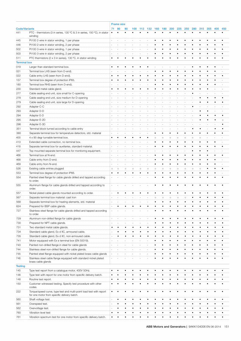
Code/Variants
Frame size
71 80 90 100 112 132 160 180 200 225 250 280 315 355 400 450441 PTC - thermistors (3 in series, 130 ºC & 3 in series, 150 ºC), in stator
winding• • • • • • • • • • • • • • • •
445 Pt100 2-wire in stator winding, 1 per phase - - - - - - • • • • • • • • • •
446 Pt100 2-wire in stator winding, 2 per phase - - - - - - • • • • • • • • • •
502 Pt100 3-wire in stator winding, 1 per phase - - - - - - • • • • • • • • • •
503 Pt100 3-wire in stator winding, 2 per phase - - - - - - • • • • • • • • • •
511 PTC thermistors (2 x 3 in series), 130 ºC, in stator winding • • • • • • • • • • • • • • • •
Terminal box
019 Larger than standard terminal box. • • • • • • - - - - - • • • • -
021 Terminal box LHS (seen from D-end). - - - - - - • • • • • • • • • -
022 Cable entry LHS (seen from D-end). • • • • • • • • • • • • • • • •
157 Terminal box degree of protection IP65. • • • • • • • • • • • • • • • -
180 Terminal box RHS (seen from D-end). - - - - - - • • • • • • • • • -
230 Standard metal cable gland. • • • • • • • • • • • • • • - -
277 Cable sealing end unit, size small for C-opening - - - - - - - - - - - • - - - -
278 Cable sealing end unit, size medium for D-opening - - - - - - - - - - - - • • • •
279 Cable sealing end unit, size large for D-opening - - - - - - - - - - - - • • • •
292 Adapter C-C - - - - - - - - - - - • - - - -
293 Adapter D-D - - - - - - - - - - - - • • - -
294 Adapter E-D - - - - - - - - - - - - • • • •
295 Adapter E-2D - - - - - - - - - - - - • • • ○
296 Adapter E-3D - - - - - - - - - - - - - - - •
351 Terminal block turned according to cable entry - - - - - - - - - - - • • - • •
380 Separate terminal box for temperature detectors, std. material - - - - - - • • • • • • • • • •
400 4 x 90 degr turnable terminal box. • • • • • • ○ ○ ○ ○ ○ ○ ○ - - -
413 Extended cable connection, no terminal box. - - - - - - • • • • • • • • • -
418 Separate terminal box for auxiliaries, standard material. - - - - - - • • • • • • • • • •
447 Top mounted separate terminal box for monitoring equipment. - - - - - - - - - - - • • • - -
466 Terminal box at N-end. - - - - - - • • • • • • • • • •
468 Cable entry from D-end. - - - - - - • • • • • • • • • -
469 Cable entry from N-end. - - - - - - • • • • • • • • • -
526 Existing cable entries plugged ○ ○ ○ ○ ○ ○ ○ ○ ○ ○ ○ ○ ○ • • •
553 Terminal box degree of protection IP66. • • • • • • • • • • • • • • • -
554 Painted steel flange for cable glands drilled and tapped according to order.
- - - - - - • • • • • • • • • •
555 Aluminum flange for cable glands drilled and tapped according to order.
- - - - - - • • • • • • • • • •
557 Nickel plated cable glands mounted according to order. - • • • • • • • • • • • • • • •
567 Separate terminal box material: cast Iron - - - - - - ○ ○ ○ ○ ○ • • • • •
568 Separate terminal box for heating elements, std. material - - - - - - • • • • • • • • • •
624 Prepared for BSP cable glands. - • • • • • • • • • • • • • • •
727 Stainless steel flange for cable glands drilled and tapped according to order.
- - - - - - • • • • • • • • • •
729 Aluminum non-drilled flange for cable glands - - - - - - • • • • • • • • • •
730 Prepared for NPT cable glands. - - - - - - • • • • • • • • • •
731 Two standard metal cable glands. • • • • • • • • • • • • • • • •
734 Standard cable gland, Ex d IIC, armoured cable. - • • • • • • • • • • • • • • •
735 Standard cable gland, Ex d IIC, non-armoured cable. - • • • • • • • • • • • • • • •
741 Motor equipped with Ex e terminal box (EN 50019). - - - - - - • • • • • • • • • •
743 Painted non-drilled flange in steel for cable glands - - - - - - • • • • • • • • • •
744 Stainless steel non-drilled flange for cable glands. - - - - - - • • • • • • • • • •
745 Painted steel flange equipped with nickel plated brass cable glands - - - - - - • • • • • • • • • •
746 Stainless steel cable flange equipped with standard nickel plated brass cable glands
- - - - - - • • • • • • • • • •
Testing
145 Type test report from a catalogue motor, 400V 50Hz. • • • • • • • • • • • • • • • •
146 Type test with report for one motor from specific delivery batch. • • • • • • • • • • • • • • • •
148 Routine test report. • • • • • • • • • • • • • • • •
150 Customer witnessed testing. Specify test procedure with other codes.
• • • • • • • • • • • • • • • •
222 Torque/speed curve, type test and multi-point load test with report for one motor from specific delivery batch.
• • • • • • • • • • • • • • • •
560 Shaft voltage test. - • • • • • • • • • • • • • • •
561 Overspeed test. - • • • • • • • • • • • • • • •
562 Overvoltage test. - • • • • • • • • • • • • • • •
760 Vibration level test • • • • • • • • • • • • • • • •
761 Vibration spectrum test for one motor from specific delivery batch. • • • • • • • • • • • • • • • •
ABB Motors and Generators | 9AKK104006 EN 06-2014 151

Code/Variants
Frame size
71 80 90 100 112 132 160 180 200 225 250 280 315 355 400 450762 Noise level test for one motor from specific delivery batch. • • • • • • • • • • • • • • • •
763 Noise spectrum test for one motor from specific delivery batch. - - - - - - • • • • • • • • • •
764 Test for one motor from specific delivery batch with ABB frequency converter available at ABB test field. ABB standard test procedure.
• • • • • • • • • • • • • • • •
Variable speed drives
470 Prepared for hollow shaft pulse tacho (L&L equivalent). - - - - - - • • • • • • • • • •
479 Mounting of other type of pulse tacho with shaft extension, tacho not included.
- - - - - - • • • • • • • • • •
680 2048 pulse tacho, Ex d, tD, L&L 841910001 - - - - - - • • • • • • • • • •
701 Insulated bearing at N-end. - - - - - - - - - - - • • • • •
704 EMC cable entry. • • • • • • • • • • • • • • • •
747 1024 pulse tacho, Ex d, tD, L&L 841910002 - - - - - - • • • • • • • • • •
○ = Included as standard• = Available as option- = Not applicable
152 9AKK104006 EN 06-2014 | ABB Catalog

M00
0178
Open
Motor frameThe motor frame, end shields and main terminal box are made of cast iron. Feet are integrated with the frame, except for sizes 160-250 with side mounted terminal box, which have detachable feet.
Motors can be supplied for foot mounting, flange mounting, and combinations of these.
Drain holesNon-sparking motors are provided with drain holes fitted with plugs as standard. The plugs are made of plastic material and delivered in open position.
When mounting arrangement differs from foot mounted IM B3, mention variant code 066 when ordering to ensure the drain plug is mounted in the lowest position.
Closed
Open
Frame size
Type of lugs Foot mounted motors Flange mounted motors
71, 80 No lugs, weight of motors is less than 25kg
- -
90-132 Detachable eye bolt
2 pcs on top of motor diagonally placed, size M8
2 pcs on top of motor diagonally placed, size M8
160-200 Integrated in casting / detachable eye bolt
2 pcs on top of motor diagonally placed, integrated in frame casting
Locations for eye bolts: 4 pcs at N-end and 4 pcs at D-end. 2 pcs eye bolts size M12 delivered with each motor
225-250 Integrated in casting / detachable eye bolt
2 pcs on top of motor diagonally placed, integrated in frame casting
Locations for eye bolts: 4 pcs at N-end and 4 pcs at D-end. 2 pcs eye bolts size M16 delivered with each motor
280, 315 Detachable eye bolt
1 pcs close to terminal box on top, size M24
Locations for eye bolts: 4 pcs at N-end and 4 pcs at D-end, one location on top close to terminal box. 2 pcs eye bolts size M24 delivered with each motor
355 Detachable eye bolt
1 pcs close to terminal box on top, size M30
Locations for eye bolts: 4 pcs at N-end and 4 pcs at D-end, one location on top close to terminal box. 2 pcs eye bolts size M30 delivered with each motor
400 Detachable eye bolt
1 pcs close to terminal box on top, size M36
Locations for eye bolts: 4 pcs at N-end and 4 pcs at D-end, one location on top close to terminal box. 2 pcs eye bolts size M36 delivered with each motor
450 Detachable eye bolt
Locations for eye bolts: 4 pcs at N-end and 4 pcs at D-end, one location on top close to terminal box. 3 pcs eye bolts size M42 delivered with each motor
Locations for eye bolts: 4 pcs at N-end and 4 pcs at D-end, one location on top close to terminal box. 2 pcs eye bolts size M42 delivered with each motor
Lifting lugsThe motors are provided as standard with liftinglugs according to the table below. For improved lifting possibilities can variant code 305 be added, please refer to the variant code section for information about availability.
Mechanical designMotor frame and drain holes
ABB Motors and Generators | 9AKK104006 EN 06-2014 153
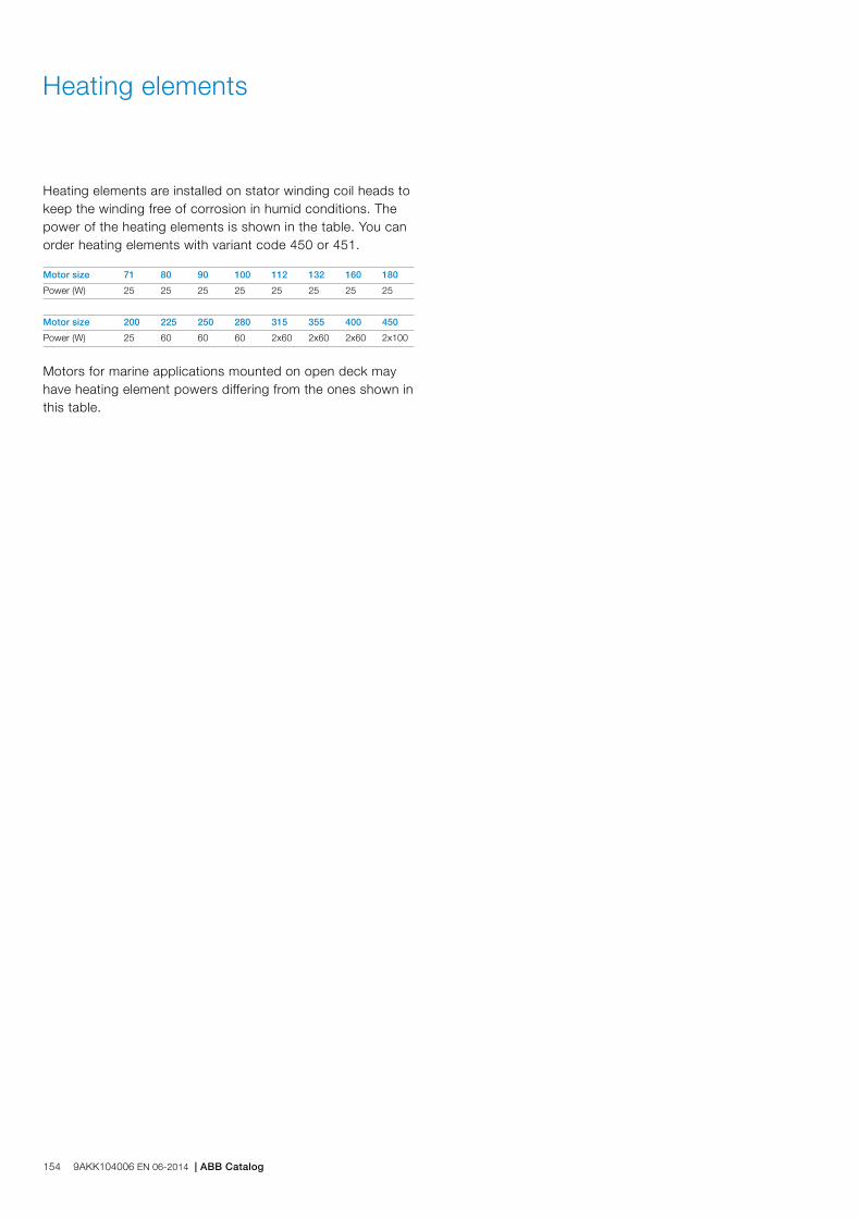
Heating elements
Heating elements are installed on stator winding coil heads to keep the winding free of corrosion in humid conditions. The power of the heating elements is shown in the table. You can order heating elements with variant code 450 or 451.
Motor size 71 80 90 100 112 132 160 180
Power (W) 25 25 25 25 25 25 25 25
Motor size 200 225 250 280 315 355 400 450
Power (W) 25 60 60 60 2x60 2x60 2x60 2x100
Motors for marine applications mounted on open deck may have heating element powers differing from the ones shown in this table.
154 9AKK104006 EN 06-2014 | ABB Catalog

Bearings
ABB’s non-sparking motors are normally fitted with single-rowdeep-groove grease lubricated ball bearings, as shown in the table below.
If the bearing at the D-end is replaced with a roller bearing (NU- or NJ-), higher radial forces can be handled. Roller bearings are suitable for belt-drive applications and can be ordered with variant code 037.
When high axial forces are involved, angular-contact ball bearings should be used. When ordering a motor with an angular-contact ball bearing, specify also the method of mounting and the direction and magnitude of axial force to ensure that optimal bearing system design is chosen. The variant codes for ordering angular-contact ball bearings at D-end are 058 and 060.
Standard and alternative designs
Motor size Number of poles
Standard design Alternative design D-end
Deep groove ball bearings Roller bearings (037) Angular contact ball bearing (058, 060)
D-end N-end D-end D-end
71 2 - 8 6203-2Z/C3 6202-2Z/C3 NA NA
80 2 - 8 6204-2Z/C3 6203-2Z/C3 NA NA
90 2 - 8 6205-2Z/C3 6204-2Z/C3 NA NA
100 2 - 8 6206-2Z/C3 6205-2Z/C3 NA NA
112 2 - 8 6206-2Z/C3 6205-2Z/C3 1) NA NA
132 2 - 8 6208-2Z/C3 6208-2Z/C3 NA NA
160 2 - 12 6309/C3 6209/C3 NU 309 ECP/C3 7309 B
180 2 - 12 6310/C3 6209/C3 NU 310 ECP/C3 7310 B
200 4 - 12 6312/C3 6210/C3 NU 312 ECP/C3 7312 B
225 4 - 12 6313/C3 6212/C3 NU 313 ECP/C3 7313 B
250 4 - 12 6315/C3 6213/C3 NU 315 ECP/C3 7315 B
280 2 6316/C3 6316/C3 2) 7316 B
4 - 12 6316/C3 6316/C3 NU 316 ECP/C3 7316 B
315 2 6316/C3 6316/C3 2) 7316 B
4 - 12 6319/C3 6316/C3 NU 319 ECP/C3 7319 B
355 2 6316M/C3 6316M/C3 2) 7316 B
4 - 12 6322/C3 6316/C3 NU 322 ECP/C3 7322 B
400 2 6317M/C3 6317M/C3 2) 7317 B
4 - 12 6324/C3 6319/C3 NU 324 ECP/C3 7324 B
450 2 6317M/C3 6317M/C3 2) 7317 B
4 - 12 6326M/C3 6322/C3 NU 326 ECP/C3 7326 B1) N-end bearing 6206-2Z/C3 on IE3 motors2) On request
ABB Motors and Generators | 9AKK104006 EN 06-2014 155
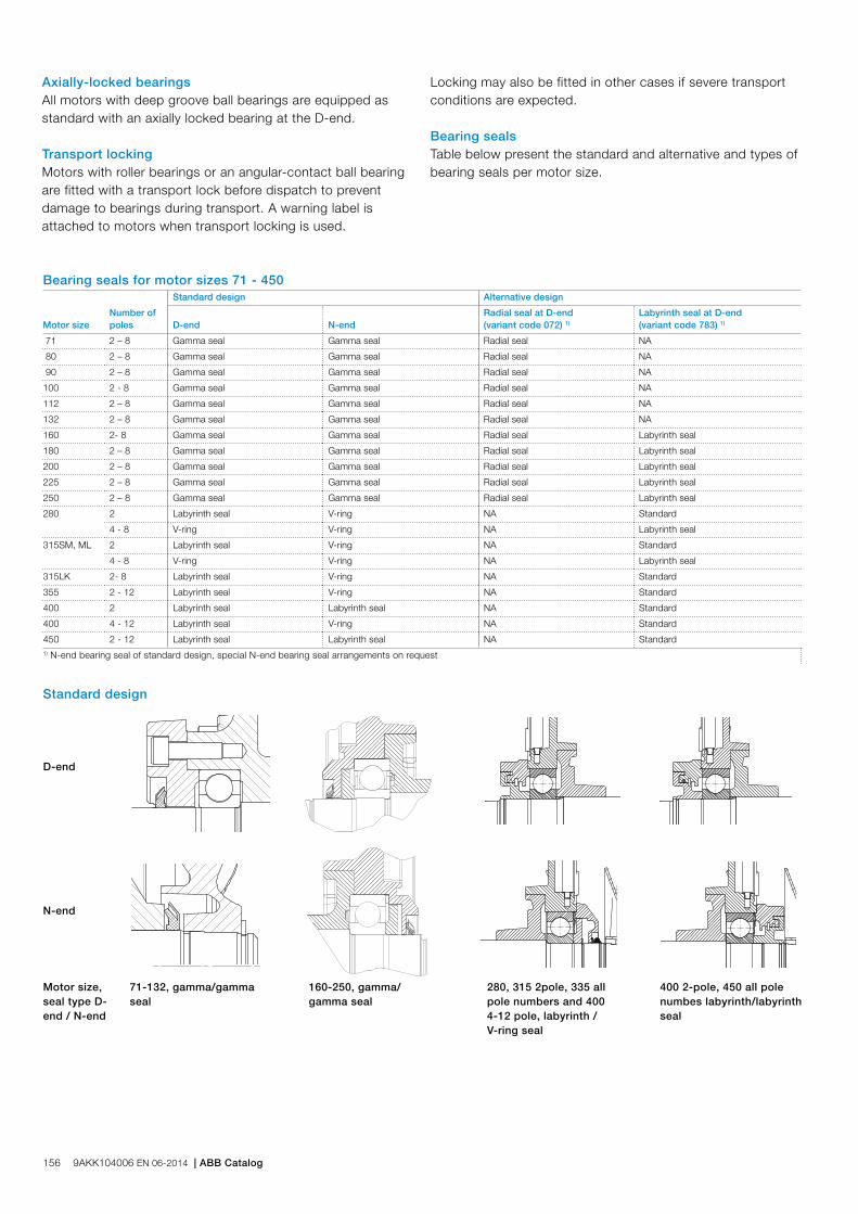
Bearing seals for motor sizes 71 - 450
Motor sizeNumber ofpoles
Standard design Alternative design
D-end N-endRadial seal at D-end (variant code 072) 1)
Labyrinth seal at D-end (variant code 783) 1)
71 2 – 8 Gamma seal Gamma seal Radial seal NA
80 2 – 8 Gamma seal Gamma seal Radial seal NA
90 2 – 8 Gamma seal Gamma seal Radial seal NA
100 2 - 8 Gamma seal Gamma seal Radial seal NA
112 2 – 8 Gamma seal Gamma seal Radial seal NA
132 2 – 8 Gamma seal Gamma seal Radial seal NA
160 2- 8 Gamma seal Gamma seal Radial seal Labyrinth seal
180 2 – 8 Gamma seal Gamma seal Radial seal Labyrinth seal
200 2 – 8 Gamma seal Gamma seal Radial seal Labyrinth seal
225 2 – 8 Gamma seal Gamma seal Radial seal Labyrinth seal
250 2 – 8 Gamma seal Gamma seal Radial seal Labyrinth seal
280 2 Labyrinth seal V-ring NA Standard
4 - 8 V-ring V-ring NA Labyrinth seal
315SM, ML 2 Labyrinth seal V-ring NA Standard
4 - 8 V-ring V-ring NA Labyrinth seal
315LK 2- 8 Labyrinth seal V-ring NA Standard
355 2 - 12 Labyrinth seal V-ring NA Standard
400 2 Labyrinth seal Labyrinth seal NA Standard
400 4 - 12 Labyrinth seal V-ring NA Standard
450 2 - 12 Labyrinth seal Labyrinth seal NA Standard1) N-end bearing seal of standard design, special N-end bearing seal arrangements on request
Standard design
D-end
N-end
Motor size,seal type D-end / N-end
71-132, gamma/gamma seal
160-250, gamma/gamma seal
280, 315 2pole, 335 all pole numbers and 400 4-12 pole, labyrinth / V-ring seal
400 2-pole, 450 all pole numbes labyrinth/labyrinth seal
Axially-locked bearingsAll motors with deep groove ball bearings are equipped as standard with an axially locked bearing at the D-end.
Transport lockingMotors with roller bearings or an angular-contact ball bearing are fitted with a transport lock before dispatch to prevent damage to bearings during transport. A warning label is attached to motors when transport locking is used.
Locking may also be fitted in other cases if severe transport conditions are expected.
Bearing sealsTable below present the standard and alternative and types of bearing seals per motor size.
156 9AKK104006 EN 06-2014 | ABB Catalog
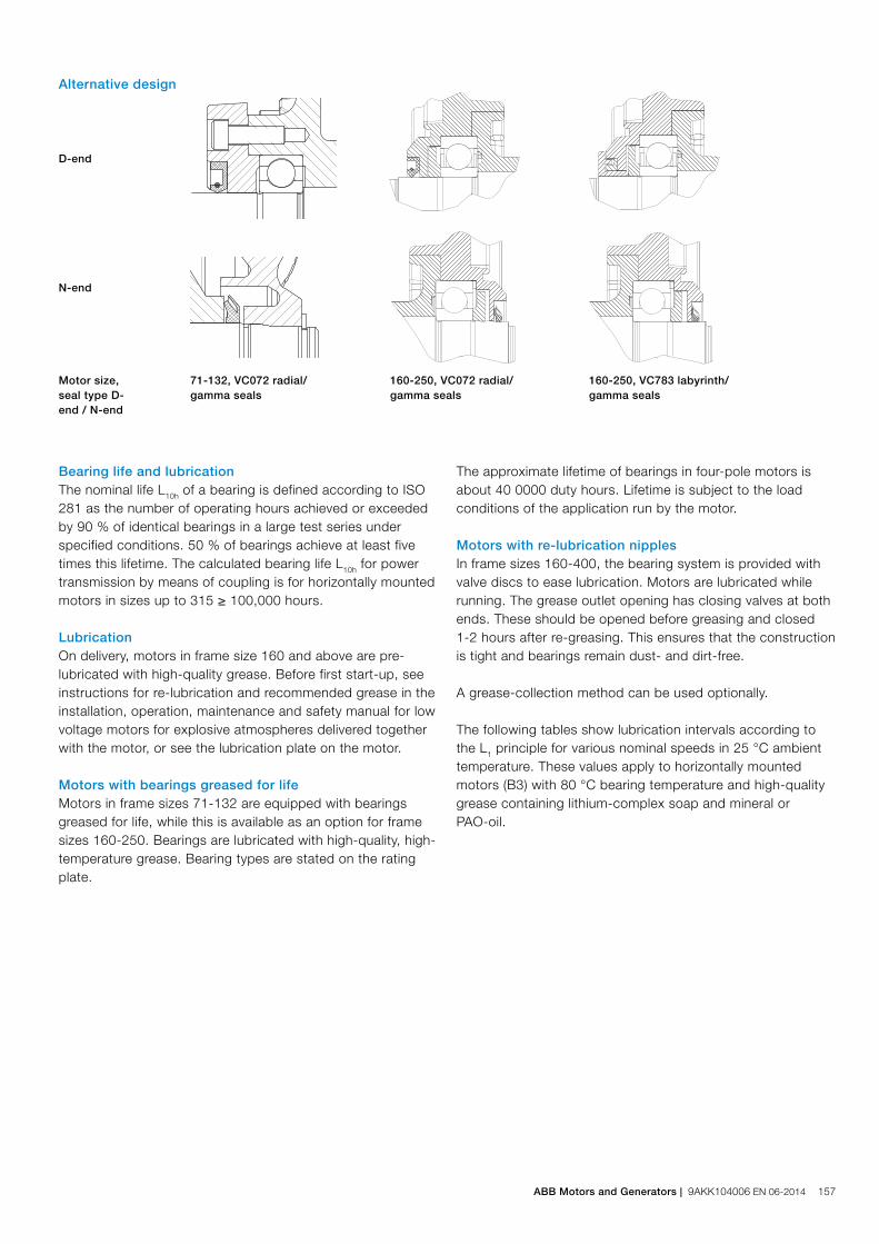
Alternative design
D-end
N-end
Motor size, seal type D-end / N-end
71-132, VC072 radial/gamma seals
160-250, VC072 radial/gamma seals
160-250, VC783 labyrinth/gamma seals
Bearing life and lubricationThe nominal life L10h of a bearing is defined according to ISO 281 as the number of operating hours achieved or exceeded by 90 % of identical bearings in a large test series under specified conditions. 50 % of bearings achieve at least five times this lifetime. The calculated bearing life L10h for power transmission by means of coupling is for horizontally mounted motors in sizes up to 315 ≥ 100,000 hours.
LubricationOn delivery, motors in frame size 160 and above are pre-lubricated with high-quality grease. Before first start-up, see instructions for re-lubrication and recommended grease in the installation, operation, maintenance and safety manual for low voltage motors for explosive atmospheres delivered together with the motor, or see the lubrication plate on the motor.
Motors with bearings greased for lifeMotors in frame sizes 71-132 are equipped with bearings greased for life, while this is available as an option for frame sizes 160-250. Bearings are lubricated with high-quality, high-temperature grease. Bearing types are stated on the rating plate.
The approximate lifetime of bearings in four-pole motors is about 40 0000 duty hours. Lifetime is subject to the load conditions of the application run by the motor.
Motors with re-lubrication nipplesIn frame sizes 160-400, the bearing system is provided with valve discs to ease lubrication. Motors are lubricated while running. The grease outlet opening has closing valves at both ends. These should be opened before greasing and closed 1-2 hours after re-greasing. This ensures that the construction is tight and bearings remain dust- and dirt-free.
A grease-collection method can be used optionally.
The following tables show lubrication intervals according to the L1 principle for various nominal speeds in 25 °C ambient temperature. These values apply to horizontally mounted motors (B3) with 80 °C bearing temperature and high-quality grease containing lithium-complex soap and mineral or PAO-oil.
ABB Motors and Generators | 9AKK104006 EN 06-2014 157

Lubrication intervals in duty hours for ball bearings
Framesize
Amountof greaseg/bearing
Amountof greaseg/N-end
OutputkW
Speed3600r/min
Speed3000r/min
OutputkW
Speed1800r/min
Speed1500r/min
OutputkW
Speed1000r/min
OutputkW
Speed500-900r/min
Ball bearings
Lubrication intervals in duty hours
160 13 13 ≤ 18.5 9000 12 000 ≤ 15 18 000 21 500 ≤ 11 24 000 all 24 000
160 13 13 > 18.5 7500 10 000 > 15 15 000 18 000 > 11 22 500 all 24 000
180 15 15 ≤ 22 7000 9000 ≤ 22 15 500 18 500 ≤ 15 24 000 all 24 000
180 15 15 > 22 6000 8500 > 22 14 000 17 000 > 15 21 000 all 24 000
200 20 15 ≤ 37 5500 8000 ≤ 30 14 500 17 500 ≤ 22 23 000 all 24 000
200 20 15 > 37 3000 5500 > 30 10 000 12 000 > 22 16 000 all 20 000
225 23 20 ≤ 45 4000 6500 ≤ 45 13 000 16 500 ≤ 30 22 000 all 24 000
250 23 20 > 45 1500 2500 > 45 5000 6000 > 30 8000 all 10 000
250 30 23 ≤ 55 2500 4000 ≤ 55 9000 11 500 ≤ 37 15 000 all 18 000
250 30 23 > 55 1000 1500 > 55 3500 4500 > 37 6000 all 7000
280 35 35 all 1900 3200 - - - -
280 40 40 - - all 7800 9600 all 13 900 all 15 000
315 35 35 all 1900 3200 - - - -
315 55 40 - - all 5900 7600 all 11 800 all 12 900
355 35 35 all 1900 3200 - - - -
355 70 40 - - all 4000 5600 all 9600 all 10 700
400 40 40 all 1500 2700 - - - -
400 85 55 - - all 3200 4700 all 8600 all 9700
450 40 40 all 1500 2700 - - - -
450 95 70 - - all 2500 3900 all 7700 all 8700
Lubrication intervals in duty hours for roller bearings
Framesize
Amountof greaseg/bearing
Amountof greaseg/N-end
OutputkW
Speed3600r/min
Speed3000r/min
OutputkW
Speed1800r/min
Speed1500r/min
OutputkW
Speed1000r/min
OutputkW
Speed500-900r/min
Roller bearings
Lubrication intervals in duty hours
160 13 13 ≤ 18.5 4500 6000 ≤ 15 9000 10 500 ≤ 11 12 000 all 12 000
160 13 13 > 18.5 3500 5000 > 15 7500 9000 > 11 11 000 all 12 000
180 15 15 ≤ 22 3500 4500 ≤ 22 7500 9000 ≤ 15 12 000 all 12 000
180 15 15 > 22 3000 4000 > 22 7000 8500 > 15 10500 all 12 000
200 20 15 ≤ 37 2750 4000 ≤ 30 7000 8500 ≤ 22 11 500 all 12 000
200 20 15 > 37 1500 2500 > 30 5000 6000 > 22 8000 all 10 000
225 23 20 ≤ 45 2000 3000 ≤ 45 6500 8000 ≤ 30 11 000 all 12 000
225 23 20 > 45 750 1250 > 45 2500 3000 > 30 4000 all 5000
250 30 23 ≤ 55 1000 2000 ≤ 55 4500 5500 ≤ 37 7500 all 9000
250 30 23 > 55 500 750 > 55 1500 2000 > 37 3000 all 3500
280 35 35 all 900 1600 - - - -
280 40 40 - - all 4000 5300 all 7000 all 8500
315 35 35 all 900 1600 - - - -
315 55 40 - - all 2900 3800 all 5900 all 6500
355 35 35 all 900 1600 - - - -
355 70 40 - - all 2000 2800 all 4800 all 5400
400 40 40 all - 1300 - - - -
400 85 55 - - all 1600 2400 all 4300 all 4800
450 40 40 all - 1300 - - - -
450 95 70 - - all 1300 2000 all 3800 all 4400
158 9AKK104006 EN 06-2014 | ABB Catalog

Radial forces
Pulley diameterWhen the desired bearing life has been determined, the minimum permissible pulley diameter can be calculated with FR as follows:
D =1.9 • 107 • K • P
n • FR
Where:
D: pulley diameter, mm
P: power requirement, kW
n: motor speed, r/min.
K: belt tension factor, dependent on belt type and type of duty. A common value for V-belts is 2.5
FR: permissible radial force, refer to tables below.
Permissible loading on the shaftThe following table shows permissible radial forces on the shaft in Newtons, assuming zero axial force, a 25 °C ambient temperature, and normal conditions. The values are given for a calculated bearing life L10h of 40 000 hours per motor size.
These calculated values further assume mounting position IM B3 (foot-mounted), with force directed sideways. In some cases, the strength of the shaft together with flame path dimensions affects permissible forces.
FR = FX0 -
X (FX0 - FXmax)E
Where:
E: length of the shaft extension in the standard version
Permissible loads of simultaneous radial and axial forces can be supplied on request.
If the radial force is applied between points X0 and Xmax, the permissible force FR can be calculated with the following formula:
Permissible radial forces, motor sizes 71–132
Motor size No. of poles
Length ofshaftextensionE (mm)
Basic design with deep groove ball bearings
Mounting arrangement IM B3
20,000 h 40,000 h
FX0(N) FXmax(N) FX0(N) FXmax(N)
71 2 30 540 460 420 360
4 30 700 605 555 480
6 30 780 665 620 530
8 30 860 730 685 580
80 2 40 710 600 385 350
4 40 940 810 725 625
6 40 1060 895 840 710
8 40 1185 1020 940 810
90 2 50 820 690 650 545
4 50 1035 870 820 690
6 50 1185 995 940 790
8 50 1300 1095 1035 870
100 2 60 1130 925 900 735
4 60 1425 1165 1135 925
6 60 1635 1335 1295 1060
8 60 1820 1520 1445 1205
112 2 60 1170 980 925 775
4 60 1475 1235 1170 980
6 60 1690 1310 1340 1120
8 60 1860 1310 1475 1235
132 2 80 1840 1500 1460 1190
4 80 2320 1890 1840 1500
6 80 2660 2165 2110 1715
8 80 2925 2380 2320 1890
ABB Motors and Generators | 9AKK104006 EN 06-2014 159

Permissible radial forces, motor sizes 160-280
Motor size Poles
Length ofshaftextensionE (mm)
Ball bearings Roller bearings
20,000 h 40,000 h 20,000 h 40,000 h
FX0(N) FXmax(N) FX0(N) FXmax(N) FX0(N) FXmax(N) FX0(N) FXmax(N)
160 MLA 2 110 3540 2740 2955 2285 7100 4300 6140 4300
4 110 4000 3100 3325 2570 8000 4300 6870 4300
6 110 4170 3200 3440 2655 8600 4300 7270 4300
8 110 4600 3585 3855 2985 9300 4300 7955 4300
160 MLB 2 110 3540 2740 2955 2270 7085 4300 6070 4300
4 110 4085 3300 3370 2725 8300 4300 7055 4300
6 110 4100 3355 3400 2755 8600 4300 7300 4300
8 110 4200 3270 3455 2670 9000 4300 7570 4300
160 MLC 2 110 3400 2600 2855 2200 6800 4300 5885 4300
4 110 3700 3000 3070 2485 7800 4300 6640 4300
6 110 3600 2900 2870 2325 8000 4300 6700 4300
8 110 4170 3370 3370 2725 9000 4300 7585 4300
160 MLD 2 110 3585 2900 3000 2440 7100 4300 6140 4300
4 110 3400 2755 2755 2240 7600 4300 6370 4300
160 MLE 2 110 3185 2570 2640 2140 6785 4300 5770 4300
180 MLA 2 110 4100 3385 3455 2825 8125 5500 7025 5500
4 110 4270 3485 3525 2885 8600 5500 7300 5500
6 110 4700 3800 3855 3155 9400 5500 7900 5500
8 110 4785 3900 3870 3170 9800 5500 8255 5500
180 MLB 2 110 4170 3400 3470 2825 7900 5500 6770 5500
4 110 4185 3400 3440 2810 8500 5500 7200 5500
6 110 4370 3570 3525 2885 9000 5500 7600 5500
180 MLC 4 110 3700 3055 3010 2470 7900 5500 6655 5440
200 MLA 2 110 5600 4685 4700 3925 10900 9100 9470 7900
4 110 6285 5200 5240 4370 12500 9550 10700 8900
6 110 6800 5700 5700 4770 13600 9550 11670 9550
8 110 6800 5700 5600 4685 14100 9550 12000 9550
200 MLB 2 110 5670 4700 4700 3925 11000 9200 9500 7900
4 110 5700 4700 4700 3925 12000 9550 10185 8500
6 110 6400 5370 5300 4425 13200 9550 11200 9385
200 MLC 2 110 5000 4185 4185 3500 10400 8700 8900 7455
4 110 5400 4500 4425 3685 11600 9550 9800 8200
6 110 5800 4885 4740 3955 12500 9550 10600 8800
200 MLD 2 110 4985 4170 4170 3485 10400 8700 8900 7400
225 SMA 2 110 6400 5400 5355 4500 13300 10700 11500 9700
4 140 7300 5900 6155 4970 15400 10250 13200 10250
6 140 7600 6200 6370 5140 16400 10250 14000 10250
8 140 8500 6900 7100 5725 17900 10250 15300 10250
225 SMB 2 110 6100 5185 5155 4340 13000 10700 11200 9455
4 140 7085 5700 5885 4755 15100 10250 12900 10250
6 140 7100 5700 5840 4700 16000 10250 13500 10250
8 140 8000 6485 6600 5340 17300 10250 14700 10250
225 SMC 2 110 5600 4700 4685 3940 12600 10600 10770 9070
4 140 6400 5200 5300 4285 14500 10250 12385 10000
225 SMD 2 110 5500 4640 4600 3880 12420 10460 10640 8960
4 140 5800 4700 4725 3800 13500 10250 11400 9270
250 SMA 2 140 7700 6285 6500 5285 17100 10900 14900 10900
4 140 8700 7000 7300 5900 19800 13800 17000 13785
6 140 9400 7600 7800 6355 21600 13800 18400 13800
8 140 9600 7800 7900 6400 22700 13800 19300 13800
250 SMB 2 140 7100 5800 6000 4885 16700 10900 14400 10900
4 140 7800 6300 6470 5240 18900 13800 16200 13100
6 140 8900 7200 7355 5955 21200 13800 18000 13800
250 SMC 2 140 6800 5500 5670 4600 16300 10900 14000 10900
4 140 7400 6000 6055 4900 18100 13800 15400 12485
6 140 8200 6600 6670 5400 20300 13800 17200 13800
280 SM_ 2 140 7300 6000 5800 4900 20400 6000 16500 6000
4 140 9200 7800 7300 6200 25100 9200 20300 9200
6 140 10600 8900 8400 7000 28300 9200 23000 9200
8 140 11700 9200 9200 7800 30900 9200 25100 9200
280 ML_ 2 140 7400 6200 5800 5000 20600 6200 16700 6200
4 140 9200 7900 7300 6200 25000 9500 20300 9500
6 140 10500 9000 8300 7100 28300 9400 22900 9400
8 140 11600 9500 9200 7900 30800 9500 25000 9500
160 9AKK104006 EN 06-2014 | ABB Catalog

Permissible radial forces, motor sizes 315-400
Motor size Poles
Length ofshaftextensionE (mm)
Ball bearings Roller bearings
20,000 h 40,000 h 20,000 h 40,000 h
FX0(N) FXmax(N) FX0(N) FXmax(N) FX0(N) FXmax(N) FX0(N) FXmax(N)
315 SM_ 2 140 7300 6000 5800 4950 20300 6000 16500 6000
4 170 11400 9400 9000 7450 32500 9600 26600 9600
6 170 13000 9600 10300 8500 37000 9600 30000 9600
8 170 14400 9600 11400 9400 40300 9600 32700 9600
315 ML_ 2 140 7400 6400 5850 5050 20600 5850 16700 5850
4 170 11500 9700 9100 7650 32700 13600 26500 13600
6 170 13200 11100 10400 8800 36900 13600 29900 13600
8 170 14500 12200 11500 9700 40200 13600 32600 13600
315 LK_ 2 140 7400 6550 5800 5150 20800 5550 16800 5550
4 170 11500 10000 9100 7850 33100 13350 26800 13350
6 170 13200 11400 10450 9050 37300 13350 30300 13350
8 170 14600 12600 11550 10000 40800 13350 33100 13350
355 SM_ 2 140 7350 6450 5750 5050 20600 7200 16700 7200
4 210 15200 12600 12000 9950 45500 14000 36900 14000
6 210 17500 14000 13800 11400 51400 14000 41700 14000
8 210 19300 14000 15250 12600 56000 14000 45500 14000
355 ML_ 2 140 7350 6550 5750 5100 20800 6750 16800 6750
4 210 15300 12900 12000 10100 45900 13600 37200 13600
6 210 17600 13600 13900 11600 51500 13600 42100 13600
8 210 19400 13600 15300 12900 56000 13600 45900 13600
355 LK_ 2 140 7350 6650 5650 5100 21000 6550 17000 6550
4 210 15200 13000 11850 10200 46000 13000 37300 13000
6 210 17500 13000 13700 11900 52000 13000 42000 13000
8 210 19400 13000 15200 13000 56500 13000 46000 13000
400 L_ 2 170 7650 6850 4400 3900 23900 9050 19350 9050
4 210 15600 13550 12150 10550 52500 16000 43300 16000
6 210 17800 15450 13850 12000 60000 16000 48800 16000
8 210 19700 16000 15350 13350 65700 16000 53200 16000
400 LK_ 2 170 7650 6850 4400 3900 23900 9050 19350 9050
4 210 15600 11500 12150 10550 52500 11500 43300 11500
6 210 17800 11500 13850 11500 60000 11500 48800 11500
8 210 19700 11500 15350 11500 65700 11500 53200 11500
450 L_ 2 170 7400 6700 3500 3300 24000 7500 19000 7500
4 210 17000 15200 13000 11600 62000 25000 50000 25000
6 210 19000 17000 14000 13000 70000 24000 56000 24000
8 210 21300 19000 16500 14600 76000 23000 62000 23000
ABB Motors and Generators | 9AKK104006 EN 06-2014 161

The following tables present permissible axial forces on the shaft in Newtons, assuming zero radial force, a 25 °C ambient temperature, and normal conditions. The values are given for a calculated bearing life of 20,000 and 40,000 hours per motor size.
At 60 Hz, the values must be reduced by 10 percent, and fortwo-speed motors, the higher speed determines permissible axial force. Permissible loads of simultaneous radial and axial forces can be supplied on request.
For axial force FAD, it is assumed that the D-bearing is locked with a locking ring.
Axial forces
Ç
FAD
M00
0023
È
FAZ
FAD Æ
M00
0022
FAZ Å
Mounting arrangement IM B3 Mounting arrangement IM V1
Permissible axial forces, motor sizes 71-132
Motor size Poles
Length ofshaftextensionE (mm)
Mounting arrangement IM B3 Mounting arrangement IM V1
Deep groove ball bearings Deep groove ball bearings
20,000 h 40,000 h 20,000 h 40,000 h
FAD(N) FAZ(N) FAD(N) FAZ(N) FAD(N) FAZ(N) FAD(N) FAZ(N)
71 2 30 615 285 505 175 630 275 520 165
4 30 760 430 615 285 790 410 645 265
6 30 870 540 695 365 890 525 720 355
8 30 960 630 765 435 985 615 785 415
80 2 40 880 300 735 155 915 280 770 135
4 40 1075 495 880 300 1130 455 935 260
6 40 1215 635 985 405 1270 600 1040 370
8 40 1330 750 1070 490 1400 705 1140 450
90 2 50 780 500 620 340 840 455 680 300
4 50 985 705 775 495 1070 650 860 440
6 50 1140 860 890 610 1225 800 975 555
8 50 1265 985 985 705 1355 925 1075 645
100 2 60 925 570 735 350 1285 510 1060 290
4 60 1480 860 1190 570 1600 780 1305 490
6 60 1690 1070 1350 730 1815 995 1470 650
8 60 1865 1245 1480 860 1995 1160 1610 775
112 2 60 1155 595 935 375 1290 505 1070 280
4 60 1445 885 1155 595 1595 785 1300 495
6 60 1655 1095 1315 755 1810 995 1465 650
8 60 1830 1270 1445 885 1985 1170 1600 780
132 2 80 1765 965 1420 620 1925 855 1580 510
4 80 2210 1410 1755 955 2420 1270 1965 815
6 80 2535 1735 2000 1200 2770 1580 2235 1045
8 80 2800 2000 2205 1405 3055 1835 2455 1235
162 9AKK104006 EN 06-2014 | ABB Catalog
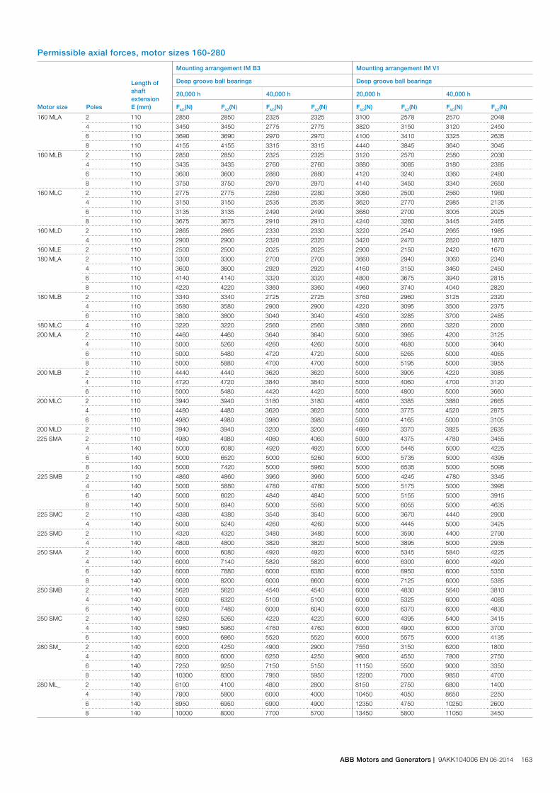
Permissible axial forces, motor sizes 160-280
Motor size Poles
Length ofshaftextensionE (mm)
Mounting arrangement IM B3 Mounting arrangement IM V1
Deep groove ball bearings Deep groove ball bearings
20,000 h 40,000 h 20,000 h 40,000 h
FAD(N) FAZ(N) FAD(N) FAZ(N) FAD(N) FAZ(N) FAD(N) FAZ(N)
160 MLA 2 110 2850 2850 2325 2325 3100 2578 2570 2048
4 110 3450 3450 2775 2775 3820 3150 3120 2450
6 110 3690 3690 2970 2970 4100 3410 3325 2635
8 110 4155 4155 3315 3315 4440 3845 3640 3045
160 MLB 2 110 2850 2850 2325 2325 3120 2570 2580 2030
4 110 3435 3435 2760 2760 3880 3085 3180 2385
6 110 3600 3600 2880 2880 4120 3240 3360 2480
8 110 3750 3750 2970 2970 4140 3450 3340 2650
160 MLC 2 110 2775 2775 2280 2280 3080 2500 2560 1980
4 110 3150 3150 2535 2535 3620 2770 2985 2135
6 110 3135 3135 2490 2490 3680 2700 3005 2025
8 110 3675 3675 2910 2910 4240 3260 3445 2465
160 MLD 2 110 2865 2865 2330 2330 3220 2540 2665 1985
4 110 2900 2900 2320 2320 3420 2470 2820 1870
160 MLE 2 110 2500 2500 2025 2025 2900 2150 2420 1670
180 MLA 2 110 3300 3300 2700 2700 3660 2940 3060 2340
4 110 3600 3600 2920 2920 4160 3150 3460 2450
6 110 4140 4140 3320 3320 4800 3675 3940 2815
8 110 4220 4220 3360 3360 4960 3740 4040 2820
180 MLB 2 110 3340 3340 2725 2725 3760 2960 3125 2320
4 110 3580 3580 2900 2900 4220 3095 3500 2375
6 110 3800 3800 3040 3040 4500 3285 3700 2485
180 MLC 4 110 3220 3220 2560 2560 3880 2660 3220 2000
200 MLA 2 110 4460 4460 3640 3640 5000 3965 4200 3125
4 110 5000 5260 4260 4260 5000 4680 5000 3640
6 110 5000 5480 4720 4720 5000 5265 5000 4065
8 110 5000 5880 4700 4700 5000 5195 5000 3955
200 MLB 2 110 4440 4440 3620 3620 5000 3905 4220 3085
4 110 4720 4720 3840 3840 5000 4060 4700 3120
6 110 5000 5480 4420 4420 5000 4800 5000 3660
200 MLC 2 110 3940 3940 3180 3180 4600 3385 3880 2665
4 110 4480 4480 3620 3620 5000 3775 4520 2875
6 110 4980 4980 3980 3980 5000 4165 5000 3105
200 MLD 2 110 3940 3940 3200 3200 4660 3370 3925 2635
225 SMA 2 110 4980 4980 4060 4060 5000 4375 4780 3455
4 140 5000 6080 4920 4920 5000 5445 5000 4225
6 140 5000 6520 5000 5260 5000 5735 5000 4395
8 140 5000 7420 5000 5960 5000 6535 5000 5095
225 SMB 2 110 4860 4860 3960 3960 5000 4245 4780 3345
4 140 5000 5880 4780 4780 5000 5175 5000 3995
6 140 5000 6020 4840 4840 5000 5155 5000 3915
8 140 5000 6940 5000 5560 5000 6055 5000 4635
225 SMC 2 110 4380 4380 3540 3540 5000 3670 4440 2900
4 140 5000 5240 4260 4260 5000 4445 5000 3425
225 SMD 2 110 4320 4320 3480 3480 5000 3590 4400 2790
4 140 4800 4800 3820 3820 5000 3895 5000 2935
250 SMA 2 140 6000 6080 4920 4920 6000 5345 5840 4225
4 140 6000 7140 5820 5820 6000 6300 6000 4920
6 140 6000 7880 6000 6380 6000 6950 6000 5350
8 140 6000 8200 6000 6600 6000 7125 6000 5385
250 SMB 2 140 5620 5620 4540 4540 6000 4830 5640 3810
4 140 6000 6320 5100 5100 6000 5325 6000 4085
6 140 6000 7480 6000 6040 6000 6370 6000 4830
250 SMC 2 140 5260 5260 4220 4220 6000 4395 5400 3415
4 140 5960 5960 4760 4760 6000 4900 6000 3700
6 140 6000 6860 5520 5520 6000 5575 6000 4135
280 SM_ 2 140 6200 4250 4900 2900 7550 3150 6200 1800
4 140 8000 6000 6250 4250 9600 4550 7800 2750
6 140 7250 9250 7150 5150 11150 5500 9000 3350
8 140 10300 8300 7950 5950 12200 7000 9850 4700
280 ML_ 2 140 6100 4100 4800 2800 8150 2750 6800 1400
4 140 7800 5800 6000 4000 10450 4050 8650 2250
6 140 8950 6950 6900 4900 12350 4750 10250 2600
8 140 10000 8000 7700 5700 13450 5800 11050 3450
ABB Motors and Generators | 9AKK104006 EN 06-2014 163
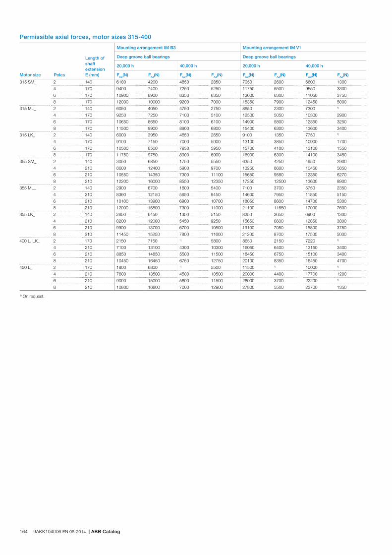
Permissible axial forces, motor sizes 315-400
Motor size Poles
Length ofshaftextensionE (mm)
Mounting arrangement IM B3 Mounting arrangement IM V1
Deep groove ball bearings Deep groove ball bearings
20,000 h 40,000 h 20,000 h 40,000 h
FAD(N) FAZ(N) FAD(N) FAZ(N) FAD(N) FAZ(N) FAD(N) FAZ(N)
315 SM_ 2 140 6180 4200 4850 2850 7950 2600 6600 1300
4 170 9400 7400 7250 5250 11750 5500 9550 3300
6 170 10900 8900 8350 6350 13600 6300 11050 3750
8 170 12000 10000 9200 7000 15350 7900 12450 5000
315 ML_ 2 140 6050 4050 4750 2750 8650 2300 7300 1)
4 170 9250 7250 7100 5100 12500 5050 10300 2900
6 170 10650 8650 8100 6100 14900 5800 12350 3250
8 170 11500 9900 8900 6800 15400 6300 13600 3400
315 LK_ 2 140 6000 3950 4650 2650 9100 1350 7750 1)
4 170 9100 7150 7000 5000 13100 3850 10900 1700
6 170 10500 8500 7950 5950 15700 4100 13100 1550
8 170 11750 9750 8900 6900 16900 6300 14100 3450
355 SM_ 2 140 3050 6850 1750 5550 6350 4250 4950 2900
4 210 8600 12400 5900 9700 13250 8600 10450 5850
6 210 10550 14350 7300 11100 15650 9580 12350 6270
8 210 12200 16000 8550 12350 17350 12500 13600 8900
355 ML_ 2 140 2900 6700 1600 5400 7100 3700 5750 2350
4 210 8360 12150 5650 9450 14600 7950 11850 5150
6 210 10100 13900 6900 10700 18050 8600 14700 5300
8 210 12000 15800 7300 11000 21100 11650 17000 7600
355 LK_ 2 140 2650 6450 1350 5150 8250 2650 6900 1300
4 210 8200 12000 5450 9250 15650 6600 12850 3800
6 210 9900 13700 6700 10500 19100 7050 15800 3750
8 210 11450 15250 7800 11600 21200 8700 17500 5000
400 L, LK_ 2 170 2150 7150 1) 5800 8650 2150 7220 1)
4 210 7100 13100 4300 10300 16050 6400 13150 3400
6 210 8850 14850 5500 11500 18450 6750 15100 3400
8 210 10450 16450 6750 12750 20100 8350 16450 4700
450 L_ 2 170 1800 6800 1) 5500 11500 1) 10000 1)
4 210 7600 13500 4500 10500 20000 4400 17700 1200
6 210 9000 15000 5600 11500 26000 3700 22200 1)
8 210 10800 16800 7000 12900 27800 5500 23700 1350
1) On request.
164 9AKK104006 EN 06-2014 | ABB Catalog
Terminal boxStandard terminal box
Protection and mounting optionsThe degree of protection for the standard terminal box is IP 55. It complies with the requirements of the protection method ‘nA’ non-sparking and prevents all ignition sources such as sparks, excessive over heating etc. The features of the terminal box are: No self loosening terminals, compliance with creepage and clearance distances as defined in standard for non-sparking protection. Terminal box with increased safety 'e' protection is optional by ordering variant code 741, see variant code section for more details.
By default, terminal boxes are mounted on top of the motor at D-end. Side mounted terminal box is possible in frame sizes 160-400. Mounting at N-end is possible for the larger frame sizes. Please refer to the variant code section for more details.
TurnabilityThe standard terminal boxes for motor sizes 160-315 can be turned 4*90°and in sizes 355-450 2*180° after delivery. For sizes 355-450 is also mounting of terminal box with opening towards D or N-end possible using the relevant variant codes when ordering, this is needed to get the terminal block turned in the right position. For motors in size 71-132 is 4*90° turnable terminal box optional, this can be ordered with variant code 400.
Cable entriesTerminal box is provided as standard with tapped holes for cable glands, no cable glands are included as standard, the entry holes are closed with Ex e approved blanking plugs made of nickel plated brass. Very large motors have angle adapters and cable sealing units as standard. Please refer to the table on next page for further information about amount and size of threaded holes, plugs and cable sealing units provided as standard.
Different types of cable glands are available as option, suitable for either armoured and non-armoured cables, please refer to the Terminal box alternatives section for more details.
Cable type and terminationsTerminations are suitable for copper and aluminum cables (Al- cables on request for motor sizes 160 to 250). Cables are connected to terminals by cable lugs, which are not included in the delivery.
Earthing boltsThe motors are as standard provided with at least one earthing bolt inside the terminal box and another on the frame. The earthing bolt on the frame is located on top close to the terminal box, motors in size 160-250 is the earthing bolt located on RHS foot (seen from D-end).
OrderingTo ensure the delivery of desired terminations and cable entries for the motor, state the cable type, quantity, size, outer diameter and possibly type of cable glands needed when ordering.
See section Variant codes for all options available.
ABB Motors and Generators | 9AKK104006 EN 06-2014 165
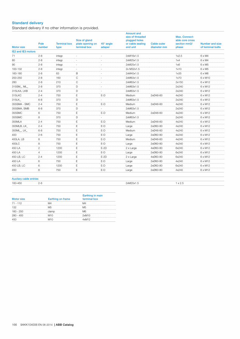
Standard deliveryStandard delivery if no other information is provided.
Motor sizePole number
Terminal box type
Size of gland plate opening on terminal box
45° angle adaper
Amount and size of threaded plugged holes or cable sealing end unit
Cable outer diameter mm
Max. Connect-able core cross section mm2/phase
Number and size of terminal bolts
IE2 and IE3 motors
71 2-8 integr. - - 2xM16x1.5 1x2.5 6 x M4
80 2-8 integr. - - 2xM25x1.5 1x4 6 x M4
90 2-8 integr. - - 2xM25x1.5 1x6 6 x M5
100-132 2-8 integr. - - 2x M32x1.5 1x10 6 x M5
160-180 2-8 63 B - 2xM40x1.5 1x35 6 x M6
200-250 2-8 160 C - 2xM63x1.5 1x70 6 x M10
280 2-8 210 C - 2xM63x1.5 2x150 6 x M12
315SM_, ML_ 2-8 370 D - 2xM63x1.5 2x240 6 x M12
315LKA, LKB 2-4 370 D - 2xM63x1.5 2x240 6 x M12
315LKC 2-4 750 E E-D Medium 2xØ48-60 4x240 6 x M12
315LK_ 6-8 370 D - 2xM63x1.5 2x240 6 x M12
355SMA - SMC 2-4 750 E E-D Medium 2xØ48-60 4x240 6 x M12
355SMA, SMB 6-8 370 D - 2xM63x1.5 2x240 6 x M12
355SMC 6 750 E E-D Medium 2xØ48-60 4x240 6 x M12
355SMC 8 370 D - 2xM63x1.5 2x240 6 x M12
355MLA 2-4 750 E E-D Medium 2xØ48-60 4x240 6 x M12
355MLB, LK_ 2-4 750 E E-D Large 2xØ60-80 4x240 6 x M12
355ML_, LK_ 6-8 750 E E-D Medium 2xØ48-60 4x240 6 x M12
400 2-6 750 E E-D Large 2xØ60-80 4x240 6 x M12
400LA, LB 8 750 E E-D Medium 2xØ48-60 4x240 6 x M12
400LC 8 750 E E-D Large 2xØ60-80 4x240 6 x M12
450 LA 2 1200 E E-2D 2 x Large 4xØ60-80 6x240 6 x M12
450 LA 4 1200 E E-D Large 2xØ60-80 6x240 6 x M12
450 LB, LC 2-4 1200 E E-2D 2 x Large 4xØ60-80 6x240 6 x M12
450 LA 6 750 E E-D Large 2xØ60-80 4x240 6 x M12
450 LB, LC 6 1200 E E-D Large 2xØ60-80 6x240 6 x M12
450 8 750 E E-D Large 2xØ60-80 4x240 6 x M12
Auxilary cable entries
160-450 2-8 2xM20x1.5 1 x 2.5
Motor size Earthing on frameEarthing in main terminal box
71 - 112 M4 M4
132 M5 M5
160 - 250 clamp M6
280 - 400 M10 2xM10
450 M10 4xM12
166 9AKK104006 EN 06-2014 | ABB Catalog

Terminal boxTerminal box dimensions
Terminal box type 1200 + adapter
Terminal box typesacc. to current capacity A1 B1 H1
Gland plateopening
63 248 248 109 B
160 291 302 154 C
210 416 306 177 C
370 451 347 200 D
750 with E-D adapter 686 413 219 D
750 without E-D adapter 523 413 219 E
1200 with E-2D adapter 1000 578 285 2xD
1200 without E-2D adapter 697 578 285 E
1200 with E-2E adapter 1195 578 285 2xE
1200 with E-3D adapter 1250 578 285 3xD
Dimensions for terminal box inletsCorresponds to motor sizes 160 and above
Flange opening
cmm
emm
fmm
gmm
dthread type
B 31 120 30 120 M6
C *) 71 194 62 193 M6
C **) 67 193 62 193 M8
D 100 300 80 292 M10
E 115 370 100 360 M12
For motor sizes 71 to 132 the terminal box is integrated in motor frame and the dimensions for terminal boxes can be found in the motor dimension drawings in ABB Library.
To match the correct terminal box with motor sizes 160-450, find the motor type and correspondent terminal box type on the previous page. The box types and heir dimensions are presented on this page.
Terminal box type 63 and 160
Terminal box types 210 and 370
Terminal box type 750 + adapter
Note! The C flange is different depending on frame size*) for frame sizes 200-225 **) for frame size 280
ABB Motors and Generators | 9AKK104006 EN 06-2014 167

Motor sizes 160-250
Terminal box for motor sizes 160-250. Connection flanges with tapped cable entries.
Terminal board for motor sizes 160-250.
The pictures below show standard terminal boxes and the corresponding terminal boards for various motor sizes. Motor sizes 71-132
Integrated terminal box for motor sizes 71-132. Tapped holes for cable entries.
Terminal board for motor sizes 71-80.
Terminal board for motor sizes 90-112, IE2, and 90-100, IE3.
Terminal board for motor size 132, IE2, and motor sizes 112-132, IE3.
Terminal boxTerminal boxes and boards
168 9AKK104006 EN 06-2014 | ABB Catalog
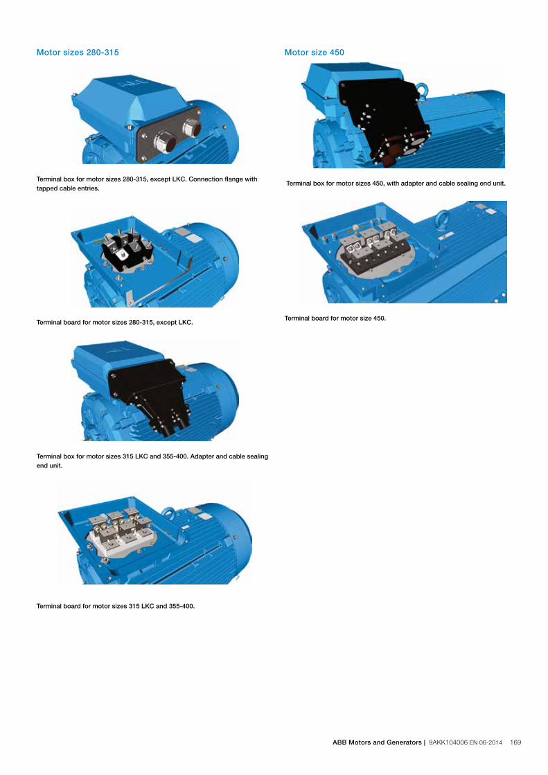
Motor size 450
Terminal box for motor sizes 450, with adapter and cable sealing end unit.
Terminal board for motor size 450.
Motor sizes 280-315
Terminal box for motor sizes 280-315, except LKC. Connection flange with tapped cable entries.
Terminal board for motor sizes 280-315, except LKC.
Terminal box for motor sizes 315 LKC and 355-400. Adapter and cable sealing end unit.
Terminal board for motor sizes 315 LKC and 355-400.
ABB Motors and Generators | 9AKK104006 EN 06-2014 169
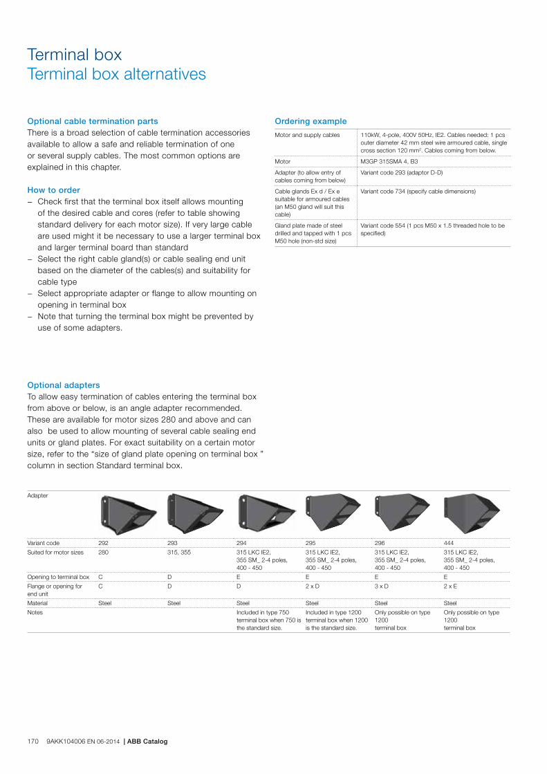
Terminal boxTerminal box alternatives
Optional cable termination partsThere is a broad selection of cable termination accessories available to allow a safe and reliable termination of one or several supply cables. The most common options are explained in this chapter.
How to order − Check first that the terminal box itself allows mounting
of the desired cable and cores (refer to table showing standard delivery for each motor size). If very large cable are used might it be necessary to use a larger terminal box and larger terminal board than standard
− Select the right cable gland(s) or cable sealing end unit based on the diameter of the cables(s) and suitability for cable type
− Select appropriate adapter or flange to allow mounting on opening in terminal box
− Note that turning the terminal box might be prevented by use of some adapters.
Optional adaptersTo allow easy termination of cables entering the terminal box from above or below, is an angle adapter recommended. These are available for motor sizes 280 and above and can also be used to allow mounting of several cable sealing end units or gland plates. For exact suitability on a certain motor size, refer to the “size of gland plate opening on terminal box ” column in section Standard terminal box.
Adapter
Variant code 292 293 294 295 296 444
Suited for motor sizes 280 315, 355 315 LKC IE2,355 SM_ 2-4 poles, 400 - 450
315 LKC IE2,355 SM_ 2-4 poles, 400 - 450
315 LKC IE2,355 SM_ 2-4 poles, 400 - 450
315 LKC IE2,355 SM_ 2-4 poles, 400 - 450
Opening to terminal box C D E E E E
Flange or opening for end unit
C D D 2 x D 3 x D 2 x E
Material Steel Steel Steel Steel Steel Steel
Notes Included in type 750 terminal box when 750 is the standard size.
Included in type 1200 terminal box when 1200 is the standard size.
Only possible on type 1200 terminal box
Only possible on type 1200 terminal box
Ordering example
Motor and supply cables 110kW, 4-pole, 400V 50Hz, IE2. Cables needed: 1 pcs outer diameter 42 mm steel wire armoured cable, single cross section 120 mm2. Cables coming from below.
Motor M3GP 315SMA 4, B3
Adapter (to allow entry of cables coming from below)
Variant code 293 (adaptor D-D)
Cable glands Ex d / Ex e suitable for armoured cables (an M50 gland will suit this cable)
Variant code 734 (specify cable dimensions)
Gland plate made of steel drilled and tapped with 1 pcs M50 hole (non-std size)
Variant code 554 (1 pcs M50 x 1.5 threaded hole to be specified)
170 9AKK104006 EN 06-2014 | ABB Catalog
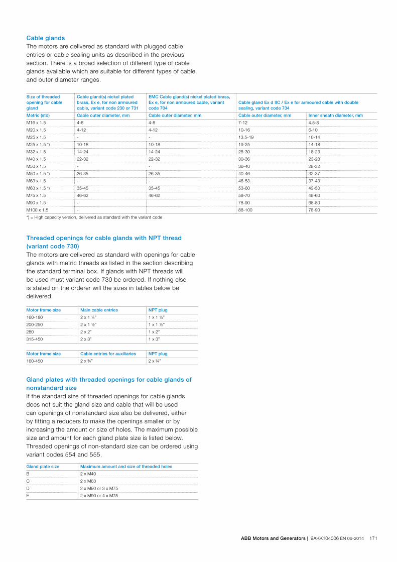
Cable glandsThe motors are delivered as standard with plugged cable entries or cable sealing units as described in the previous section. There is a broad selection of different type of cable glands available which are suitable for different types of cable and outer diameter ranges.
Size of threaded opening for cable gland
Cable gland(s) nickel plated brass, Ex e, for non armoured cable, variant code 230 or 731
EMC Cable gland(s) nickel plated brass, Ex e, for non armoured cable, variant code 704
Cable gland Ex d IIC / Ex e for armoured cable with double sealing, variant code 734
Metric (std) Cable outer diameter, mm Cable outer diameter, mm Cable outer diameter, mm Inner sheath diameter, mm
M16 x 1.5 4-8 4-8 7-12 4.5-8
M20 x 1.5 4-12 4-12 10-16 6-10
M25 x 1.5 - - 13.5-19 10-14
M25 x 1.5 *) 10-18 10-18 19-25 14-18
M32 x 1.5 14-24 14-24 25-30 18-23
M40 x 1.5 22-32 22-32 30-36 23-28
M50 x 1.5 - - 36-40 28-32
M50 x 1.5 *) 26-35 26-35 40-46 32-37
M63 x 1.5 - - 46-53 37-43
M63 x 1.5 *) 35-45 35-45 53-60 43-50
M75 x 1.5 46-62 46-62 58-70 48-60
M90 x 1.5 - 78-90 68-80
M100 x 1.5 - 88-100 78-90
*) = High capacity version, delivered as standard with the variant code
Threaded openings for cable glands with NPT thread (variant code 730)The motors are delivered as standard with openings for cable glands with metric threads as listed in the section describing the standard terminal box. If glands with NPT threads will be used must variant code 730 be ordered. If nothing else is stated on the orderer will the sizes in tables below be delivered.
Motor frame size Main cable entries NPT plug
160-180 2 x 1 ¼” 1 x 1 ¼”
200-250 2 x 1 ½” 1 x 1 ½”
280 2 x 2” 1 x 2”
315-450 2 x 3” 1 x 3”
Motor frame size Cable entries for auxiliaries NPT plug
160-450 2 x ¾” 2 x ¾”
Gland plates with threaded openings for cable glands of nonstandard sizeIf the standard size of threaded openings for cable glands does not suit the gland size and cable that will be used can openings of nonstandard size also be delivered, either by fitting a reducers to make the openings smaller or by increasing the amount or size of holes. The maximum possible size and amount for each gland plate size is listed below. Threaded openings of non-standard size can be ordered using variant codes 554 and 555.
Gland plate size Maximum amount and size of threaded holes
B 2 x M40
C 2 x M63
D 2 x M90 or 3 x M75
E 2 x M90 or 4 x M75
ABB Motors and Generators | 9AKK104006 EN 06-2014 171

Small Medium Large
End unit
Variant code 277 278 279
Suited for motor sizes 280 315, 355, except 315 LKC IE2,355 SM_ 2-4 poles
315, 355, except 315 LKC IE2,355 SM_ 2-4 poles
Opening to terminal box C D D
Cable outer diameter 1 - 2 cables, 48 - 60 mm 1 - 2 cables, 48 - 60 mm 1 - 2 cables, 60 - 80 mm
Cable entry for auxiliary cable 2 x M20 plugged holes
2 x M20 plugged holes
2 x M20 plugged holes
Additional optional variants EMC cable gland (704);Standard gland with clamping device (231)
EMC cable gland (704);Standard gland with clamping device (231)
EMC cable gland (704);Standard gland with clamping device (231)
Gland plates of non-standard materialThe standard material used in gland plates is steel. Gland plates made of aluminum or stainless steel are optional, either with cable glands or blind without threaded holes. Please refer to the variant code section for more information.
Cable sealing end unitsAs an alternative to gland plates and cable glands, cable sealing end units can be used. These allow more space for spreading the cores for easy termination. Cable sealing units have rubber sealed entries for one or two main cables. In addition there are two plugged M20 holes for auxiliary cables. The cable sealing end units are Ex e certified, as option can they be equipped with EMC modules or cable clamping devices by adding variant codes 704 or 231.
172 9AKK104006 EN 06-2014 | ABB Catalog
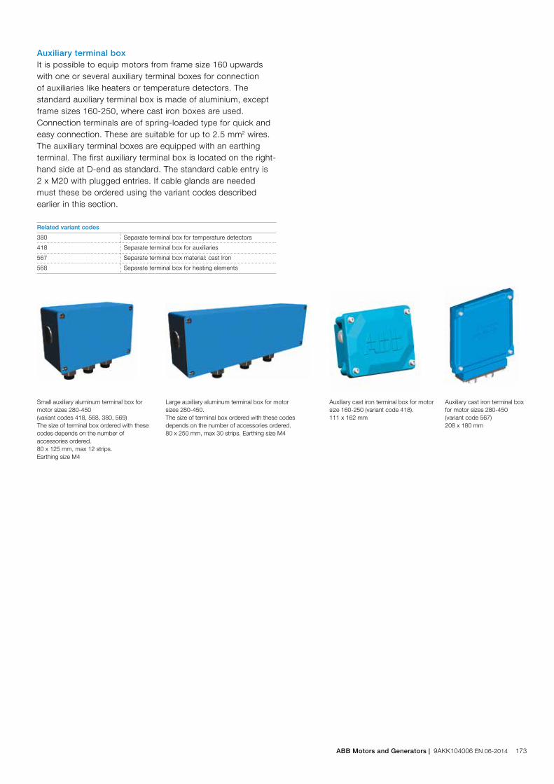
Auxiliary terminal boxIt is possible to equip motors from frame size 160 upwards with one or several auxiliary terminal boxes for connection of auxiliaries like heaters or temperature detectors. The standard auxiliary terminal box is made of aluminium, except frame sizes 160-250, where cast iron boxes are used. Connection terminals are of spring-loaded type for quick and easy connection. These are suitable for up to 2.5 mm2 wires. The auxiliary terminal boxes are equipped with an earthing terminal. The first auxiliary terminal box is located on the right-hand side at D-end as standard. The standard cable entry is 2 x M20 with plugged entries. If cable glands are needed must these be ordered using the variant codes described earlier in this section.
Related variant codes
380 Separate terminal box for temperature detectors
418 Separate terminal box for auxiliaries
567 Separate terminal box material: cast Iron
568 Separate terminal box for heating elements
Small auxiliary aluminum terminal box for motor sizes 280-450 (variant codes 418, 568, 380, 569)The size of terminal box ordered with these codes depends on the number of accessories ordered.80 x 125 mm, max 12 strips. Earthing size M4
Large auxiliary aluminum terminal box for motor sizes 280-450.The size of terminal box ordered with these codes depends on the number of accessories ordered.80 x 250 mm, max 30 strips. Earthing size M4
Auxiliary cast iron terminal box for motor size 160-250 (variant code 418). 111 x 162 mm
Auxiliary cast iron terminal boxfor motor sizes 280-450 (variant code 567) 208 x 180 mm
ABB Motors and Generators | 9AKK104006 EN 06-2014 173

L
C BB’
E
H
KA
HD
GA
FD
P N
45°
SM
MS
45°
Foot-mounted motor IM 1001, IM B3
Sizes 80 to 200 Protective roof, variant code 005
M00
0267
M00
0268
M00
0270
M00
0269
M00
0271
M00
0272
M00
0230
M00
0231
Flange-mounted motor IM 3001, IM B5
Sizes 225 to 450
IM B14 (IM3601), IM 3602
Motor size
IM 1001, IM B3 AND IM 3001, IM B5 IM 1001, IM B3 IM 3001, IM B5 Protective roof
Dpoles
GApoles
Fpoles
Epoles
L maxpoles A B B' C HD K H M N P S DS LS
2 4-8 2 4-8 2 4-8 2 4-8 2 4-6 2 4-8
71 14 14 16 16 5 5 30 30 264 264 112 90 - 45 178 7 130 110 160 10 - 272.5 272.5
80 19 19 21.5 21.5 6 6 40 40 321 321 125 100 - 50 195 10 165 130 200 12 - 331 331 360
90 24 24 27 27 8 8 50 50 357 357 140 100 125 56 219 10 165 130 200 12 - 368.5 368.5 430
100 28 28 31 31 8 8 60 60 381 381 160 140 - 63 247 12 215 180 250 15 - 395 395 505
112 28 28 31 31 8 8 60 60 403 403 190 140 - 70 259 12 215 180 250 15 - 417 417 505
132 38 38 41 41 10 10 80 80 533 533 216 140 178 89 300 12 265 230 300 15 - 551.5 551.5 590
160 42 42 45 45 12 12 110 110 808 808 254 210 254 108 499 14.5 160 300 250 350 18.5 328 756 756
180 48 48 51.5 51.5 14 14 110 110 826 826 279 241 279 121 539 14.6 180 300 250 350 18.5 359 756 756
200 55 55 59 59 16 16 110 110 774 774 318 267 305 133 536 18.5 200 350 300 400 18.5 414 844 844
225 55 60 59 64 16 18 110 140 841 871 356 286 311 149 583 18.6 225 400 350 450 18.5 462 921 951
250 60 65 64 69 18 18 140 140 875 875 406 311 349 168 646 24 250 500 450 550 18.5 506 965 965
280 65 75 69 79.5 18 20 140 140 1088 1088 457 368 419 190 759 24 280 500 450 550 18 555 1190 1190
315 SM_ 65 80 69 85 18 22 140 170 1174 1204 508 406 457 216 852 30 315 600 550 660 23 624 1290 1320
315 ML_ 65 90 69 95 18 25 140 170 1285 1315 508 457 508 216 852 30 315 600 550 660 23 624 1401 1431
355 SM_ 70 100 62.5 90 20 28 140 210 1409 1479 610 500 560 254 958 35 355 740 680 800 23 720 1476 1546
355 ML_ 70 100 62.5 90 20 28 140 210 1514 1584 610 560 630 254 958 35 355 740 680 800 23 720 1528 1703
355 LK_ 70 100 62.5 90 20 28 140 210 1764 1834 610 710 900 254 958 35 355 740 680 800 23 720 1633 1703
400 L_ 80 110 85 126 22 28 170 210 1851 1891 710 900 1000 224 1045 35 400 940 880 1000 28 810 1860 1900
400 LK_ 80 100 85 106 22 28 170 210 1851 1891 686 710 800 280 1045 35 400 740 680 800 24 810 1860 1900
450 - 120 - 127 - 32 - 210 - 2187 800 1000 1120 250 1169 42 450 1080 1000 1150 28 On request
Motor size LA M N P S T S T
71 8 85 70 105 M6 2.5 M6 2.5
80 8 100 80 120 M6 3 M6 3
90 10 115 95 140 M8 3 M8 3
100 10 130 110 160 M8 3.5 M8 3.5
112 10 130 110 160 M8 3.5 M8 3.5
132 12 165 130 200 M10 3.5 M10 3.5
Dimension drawingsNon-sparking cast iron motors, Ex nA
Tolerances:
A, B ± 0,8
D, DA ISO k6 < Ø 50mm
ISO m6 > Ø 50mm
F, FA ISO h9
H -0.5
N ISO j6
C, CA ± 0.8
In all dimension drawings: The tables give the main dimensions in mm. For detailed drawings please see our web-pages ‘www.abb.com/motors&generators’ or contact ABB.
174 9AKK104006 EN 06-2014 | ABB Catalog
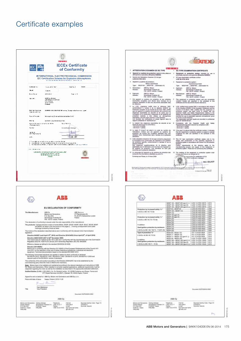
M00
0731
M00
0730
Certificate examples
M00
0725
-2a
M00
0725
-1a
ABB Motors and Generators | 9AKK104006 EN 06-2014 175
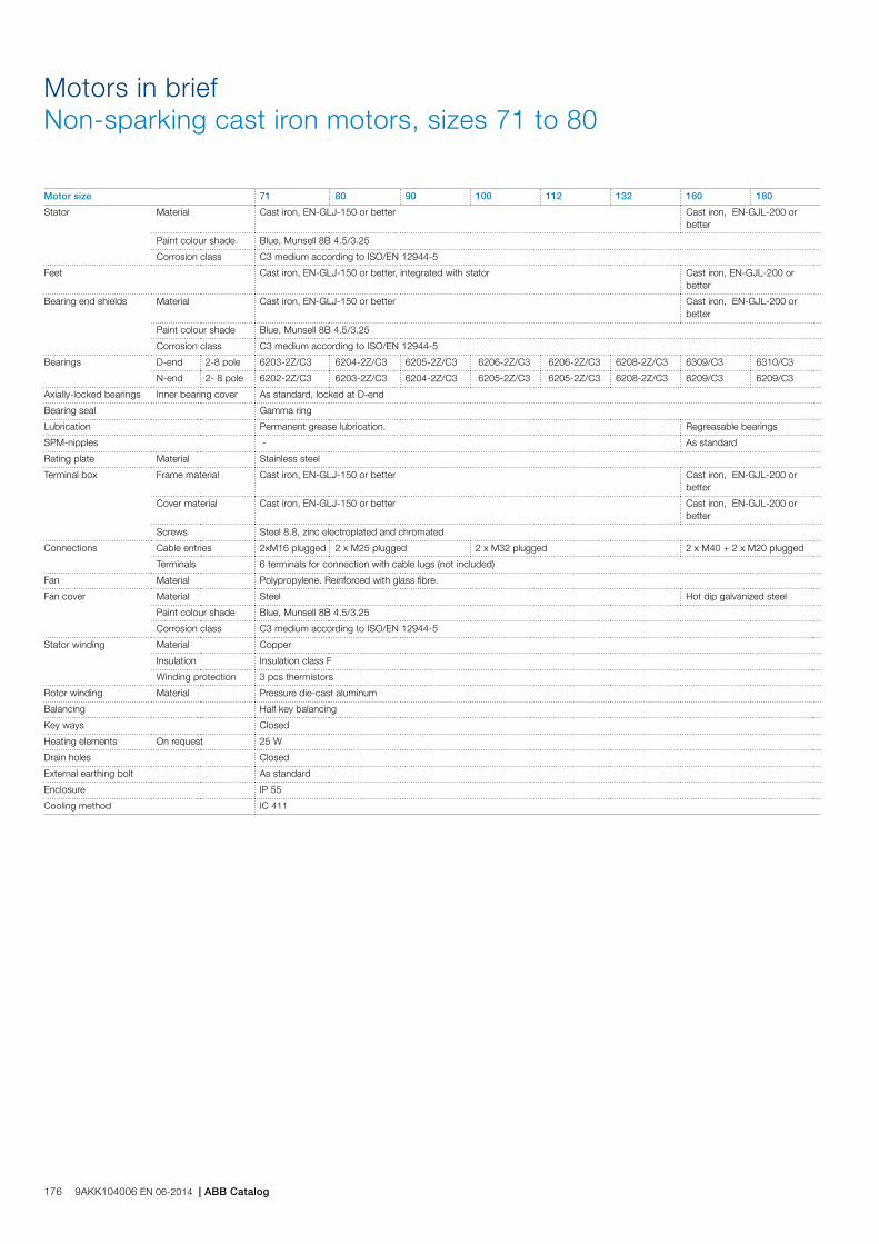
Motor size 71 80 90 100 112 132 160 180
Stator Material Cast iron, EN-GLJ-150 or better Cast iron, EN-GJL-200 or better
Paint colour shade Blue, Munsell 8B 4.5/3.25
Corrosion class C3 medium according to ISO/EN 12944-5
Feet Cast iron, EN-GLJ-150 or better, integrated with stator Cast iron, EN-GJL-200 or better
Bearing end shields Material Cast iron, EN-GLJ-150 or better Cast iron, EN-GJL-200 or better
Paint colour shade Blue, Munsell 8B 4.5/3.25
Corrosion class C3 medium according to ISO/EN 12944-5
Bearings D-end 2-8 pole 6203-2Z/C3 6204-2Z/C3 6205-2Z/C3 6206-2Z/C3 6206-2Z/C3 6208-2Z/C3 6309/C3 6310/C3
N-end 2- 8 pole 6202-2Z/C3 6203-2Z/C3 6204-2Z/C3 6205-2Z/C3 6205-2Z/C3 6208-2Z/C3 6209/C3 6209/C3
Axially-locked bearings Inner bearing cover As standard, locked at D-end
Bearing seal Gamma ring
Lubrication Permanent grease lubrication. Regreasable bearings
SPM-nipples - As standard
Rating plate Material Stainless steel
Terminal box Frame material Cast iron, EN-GLJ-150 or better Cast iron, EN-GJL-200 or better
Cover material Cast iron, EN-GLJ-150 or better Cast iron, EN-GJL-200 or better
Screws Steel 8.8, zinc electroplated and chromated
Connections Cable entries 2xM16 plugged 2 x M25 plugged 2 x M32 plugged 2 x M40 + 2 x M20 plugged
Terminals 6 terminals for connection with cable lugs (not included)
Fan Material Polypropylene. Reinforced with glass fibre.
Fan cover Material Steel Hot dip galvanized steel
Paint colour shade Blue, Munsell 8B 4.5/3.25
Corrosion class C3 medium according to ISO/EN 12944-5
Stator winding Material Copper
Insulation Insulation class F
Winding protection 3 pcs thermistors
Rotor winding Material Pressure die-cast aluminum
Balancing Half key balancing
Key ways Closed
Heating elements On request 25 W
Drain holes Closed
External earthing bolt As standard
Enclosure IP 55
Cooling method IC 411
Motors in briefNon-sparking cast iron motors, sizes 71 to 80
176 9AKK104006 EN 06-2014 | ABB Catalog
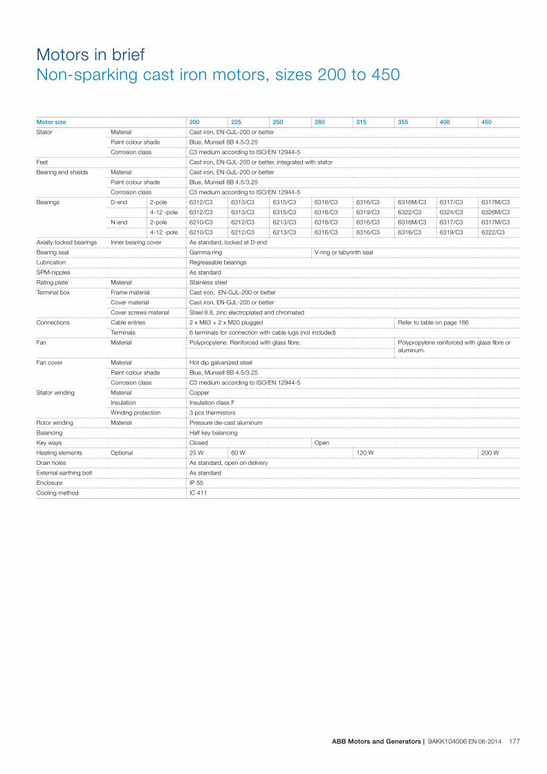
Motor size 200 225 250 280 315 355 400 450
Stator Material Cast iron, EN-GJL-200 or better
Paint colour shade Blue, Munsell 8B 4.5/3.25
Corrosion class C3 medium according to ISO/EN 12944-5
Feet Cast iron, EN-GJL-200 or better, integrated with stator
Bearing end shields Material Cast iron, EN-GJL-200 or better
Paint colour shade Blue, Munsell 8B 4.5/3.25
Corrosion class C3 medium according to ISO/EN 12944-5
Bearings D-end 2-pole 6312/C3 6313/C3 6315/C3 6316/C3 6316/C3 6316M/C3 6317/C3 6317M/C3
4-12 -pole 6312/C3 6313/C3 6315/C3 6316/C3 6319/C3 6322/C3 6324/C3 6326M/C3
N-end 2-pole 6210/C3 6212/C3 6213/C3 6316/C3 6316/C3 6316M/C3 6317/C3 6317M/C3
4-12 -pole 6210/C3 6212/C3 6213/C3 6316/C3 6316/C3 6316/C3 6319/C3 6322/C3
Axially-locked bearings Inner bearing cover As standard, locked at D-end
Bearing seal Gamma ring V-ring or labyrinth seal
Lubrication Regreasable bearings
SPM-nipples As standard
Rating plate Material Stainless steel
Terminal box Frame material Cast iron, EN-GJL-200 or better
Cover material Cast iron, EN-GJL-200 or better
Cover screws material Steel 8.8, zinc electroplated and chromated
Connections Cable entries 2 x M63 + 2 x M20 plugged Refer to table on page 166
Terminals 6 terminals for connection with cable lugs (not included)
Fan Material Polypropylene. Reinforced with glass fibre. Polypropylene reinforced with glass fibre or aluminum.
Fan cover Material Hot dip galvanized steel
Paint colour shade Blue, Munsell 8B 4.5/3.25
Corrosion class C3 medium according to ISO/EN 12944-5
Stator winding Material Copper
Insulation Insulation class F
Winding protection 3 pcs thermistors
Rotor winding Material Pressure die-cast aluminum
Balancing Half key balancing
Key ways Closed Open
Heating elements Optional 25 W 60 W 120 W 200 W
Drain holes As standard, open on delivery
External earthing bolt As standard
Enclosure IP 55
Cooling method IC 411
Motors in briefNon-sparking cast iron motors, sizes 200 to 450
ABB Motors and Generators | 9AKK104006 EN 06-2014 177
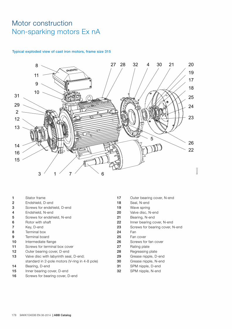
Motor constructionNon-sparking motors Ex nA
Typical exploded view of cast iron motors, frame size 315
1 Stator frame 2 Endshield, D-end 3 Screws for endshield, D-end 4 Endshield, N-end 5 Screws for endshield, N-end 6 Rotor with shaft 7 Key, D-end 8 Terminal box 9 Terminal board 10 Intermediate flange 11 Screws for terminal box cover 12 Outer bearing cover, D-end 13 Valve disc with labyrinth seal, D-end; standard in 2-pole motors (V-ring in 4-8 pole) 14 Bearing, D-end 15 Inner bearing cover, D-end 16 Screws for bearing cover, D-end
M00
0220
17 Outer bearing cover, N-end 18 Seal, N-end 19 Wave spring 20 Valve disc, N-end 21 Bearing, N-end 22 Inner bearing cover, N-end 23 Screws for bearing cover, N-end 24 Fan 25 Fan cover 26 Screws for fan cover 27 Rating plate 28 Regreasing plate 29 Grease nipple, D-end 30 Grease nipple, N-end 31 SPM nipple, D-end 32 SPM nipple, N-end
178 9AKK104006 EN 06-2014 | ABB Catalog

Non-sparking aluminum motors Ex nATotally enclosed squirrel cage three phase low voltage motors, Sizes 90 to 280, 2.2 to 90 kW
Ordering information 180
Rating plates 181
Technical data 182
IE2 3000 r/min motors 182
IE2 1500 r/min motors 183
IE2 1000 r/min motors 184
Variant codes 185
Mechanical design 188
Motor frame and drain holes 188
Bearings 189
Terminal box 194
Dimension drawings 195
Aluminum motors in brief 196
ABB Motors and Generators | 9AKK104006 EN 02-2016 179
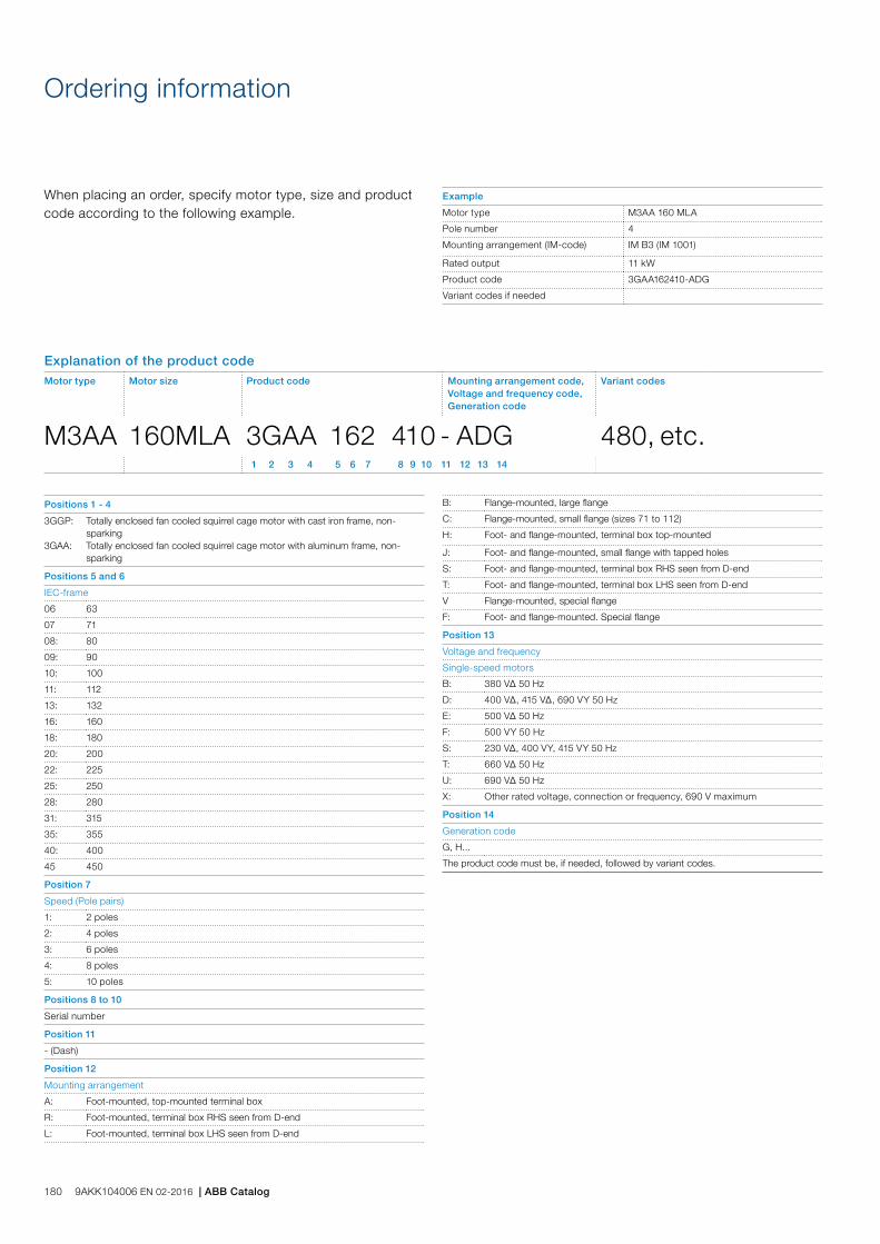
When placing an order, specify motor type, size and product code according to the following example.
Positions 1 - 4
3GGP:
3GAA:
Totally enclosed fan cooled squirrel cage motor with cast iron frame, non-sparkingTotally enclosed fan cooled squirrel cage motor with aluminum frame, non-sparking
Positions 5 and 6
IEC-frame
06 63
07 71
08: 80
09: 90
10: 100
11: 112
13: 132
16: 160
18: 180
20: 200
22: 225
25: 250
28: 280
31: 315
35: 355
40: 400
45 450
Position 7
Speed (Pole pairs)
1: 2 poles
2: 4 poles
3: 6 poles
4: 8 poles
5: 10 poles
Positions 8 to 10
Serial number
Position 11
- (Dash)
Position 12
Mounting arrangement
A: Foot-mounted, top-mounted terminal box
R: Foot-mounted, terminal box RHS seen from D-end
L: Foot-mounted, terminal box LHS seen from D-end
Ordering information
B: Flange-mounted, large flange
C: Flange-mounted, small flange (sizes 71 to 112)
H: Foot- and flange-mounted, terminal box top-mounted
J: Foot- and flange-mounted, small flange with tapped holes
S: Foot- and flange-mounted, terminal box RHS seen from D-end
T: Foot- and flange-mounted, terminal box LHS seen from D-end
V Flange-mounted, special flange
F: Foot- and flange-mounted. Special flange
Position 13
Voltage and frequency
Single-speed motors
B: 380 VΔ 50 Hz
D: 400 VΔ, 415 VΔ, 690 VY 50 Hz
E: 500 VΔ 50 Hz
F: 500 VY 50 Hz
S: 230 VΔ, 400 VY, 415 VY 50 Hz
T: 660 VΔ 50 Hz
U: 690 VΔ 50 Hz
X: Other rated voltage, connection or frequency, 690 V maximum
Position 14
Generation code
G, H...
The product code must be, if needed, followed by variant codes.
Explanation of the product codeMotor type Motor size Product code Mounting arrangement code,
Voltage and frequency code,Generation code
Variant codes
M3AA 160MLA 3GAA 162 410 - ADG 480, etc. 1 2 3 4 5 6 7 8 9 10 11 12 13 14
Example
Motor type M3AA 160 MLA
Pole number 4
Mounting arrangement (IM-code) IM B3 (IM 1001)
Rated output 11 kW
Product code 3GAA162410-ADG
Variant codes if needed
180 9AKK104006 EN 02-2016 | ABB Catalog
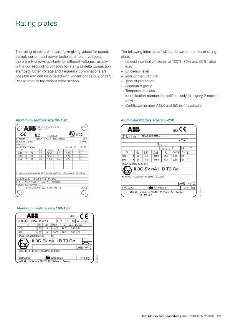
Rating plates
The rating plates are in table form giving values for speed, output, current and power factor at different voltages, there are two rows available for different voltages, usually is the corresponding voltages for star and delta connection stamped. Other voltage and frequency combinations are possible and can be ordered with variant codes 002 or 209. Please refer to the variant code section.
The following information will be shown on the motor rating plate:
− Lowest nominal efficiency at 100%, 75% and 50% rated load
− Efficiency level − Year of manufacture − Type of protection − Apparatus group − Temperature class − Identification number for notified body (category 2 motors
only) − Certificate number ATEX and IECEx (if available)
M00
0751
a
M00
0752
a
Aluminum motors size 90-132
Aluminum motors size 160-180
Aluminum motors size 200-250
Plates
ABB Motors and Generators | 9AKK104006 EN 02-2016 181

Output kW Motor type Product code
Speed r/min
Efficiency Power factor cos j
Current Torque Moment of inertiaJ = 1/4 GD2 kgm2
Weight kg
Sound pressure level LPA dB
Full load 100%
3/4 load 75%
1/2 load 50%
IN A
Is IN
TN Nm
Tl TN
Tb TN
3000 r/min = 2-poles 400 V 50 Hz CENELEC-design
1.5 M3AA 90L 2 3GAA091500-••E 2900 84.1 85.0 83.5 0.86 2.9 7.6 4.9 2.5 3.3 0.0024 16 60
2.2 M3AA 90LB 2 3GAA091520-••E 2870 84.6 85.6 84.8 0.86 4.4 6.9 7.3 2.8 3.2 0.0027 18 63
3 M3AA 100LB 2 3GAA101520-••E 2920 86.4 86.1 84.0 0.86 5.8 9.3 9.8 3.3 3.9 0.005 25 62
4 M3AA 112MB 2 3GAA111320-••E 2885 86.1 87.0 88.0 0.88 7.6 7.6 13.2 2.5 2.8 0.0062 30 68
5.5 M3AA 132SB 2 3GAA131120-••E 2915 88.0 88.1 86.9 0.82 11.0 7.9 18.0 2.6 3.6 0.016 42 73
7.5 M3AA 132SC 2 3GAA131130-••E 2915 88.5 89.1 88.5 0.88 13.6 7.6 24.5 2.2 3.2 0.022 56 73
11 M3AA 160MLA 2 3GAA161410-••G 2938 90.6 91.5 91.1 0.90 19.2 7.5 35.7 2.4 3.1 0.044 91 69
15 M3AA 160MLB 2 3GAA161420-••G 2934 91.5 92.4 92.2 0.90 26.0 7.5 48.8 2.5 3.3 0.053 105 69
18.5 M3AA 160MLC 2 3GAA161430-••G 2932 92.0 93.1 93.1 0.92 31.5 7.5 60.2 2.9 3.4 0.063 123 69
22 M3AA 180MLA 2 3GAA181410-••G 2952 92.2 92.7 92.2 0.87 39.5 7.7 71.1 2.8 3.3 0.076 132 69
30 M3AA 200MLA 2 3GAA201410-••G 2956 93.1 93.5 92.8 0.90 51.6 7.7 96.9 2.7 3.1 0.178 210 72
37 M3AA 200MLB 2 3GAA201420-••G 2959 93.4 93.7 92.9 0.90 63.5 8.2 119 3.0 3.3 0.196 225 72
45 M3AA 225SMA 2 3GAA221210-••G 2961 93.6 93.9 93.1 0.88 78.8 6.7 145 2.5 2.5 0.244 263 74
55 M3AA 250SMA 2 3GAA251210-••G 2967 94.1 94.4 93.8 0.88 95.8 6.8 177 2.2 2.7 0.507 304 75
75 M3AA 280SMA 2 3GAA281210-••G 2968 94.4 94.7 94.3 0.89 128 7.1 241 2.5 2.8 0.583 389 75
90 1) M3AA 280SMB 2 3GAA281220-••G 2971 94.9 95.2 94.7 0.89 153 7.8 289 2.6 3.2 0.644 425 75
3000 r/min = 2-poles 400 V 50 Hz High-output design
30 M3AA 180MLB 2 3GAA181420-••G 2950 92.7 93.5 93.3 0.88 53.0 7.9 97.1 2.8 3.3 0.092 149 69
45 M3AA 200MLC 2 3GAA201430-••G 2957 93.3 93.8 93.2 0.88 79.1 8.1 145 3.1 3.3 0.196 225 72
55 M3AA 225SMB 2 3GAA221220-••G 2961 93.9 94.3 93.6 0.88 96.0 6.5 177 2.4 2.5 0.274 286 74
75 M3AA 250SMB 2 3GAA251220-••G 2970 94.5 94.8 94.4 0.89 128 7.6 241 2.8 3.1 0.583 351 75
IP 55 - IC 411 - Insulation class F, temperature rise class BIE2 efficiency class according to IEC 60034-30-1; 2014
Technical data for Ex nA IIB/C T3 Gc Non-sparking aluminum motors
1) Temperature rise class F
The following variant codes must be selected for aluminum non-sparking motors: Sizes 90-132 variant 456, sizes 160-280 variant 480.
Motors in frame size 90-132 are marked for gas group IIC and sizes 160-280 IIB
182 9AKK104006 EN 02-2016 | ABB Catalog

IP 55 - IC 411 - Insulation class F, temperature rise class BIE2 efficiency class according to IEC 60034-30-1; 2014
Technical data for Ex nA IIB/C T3 Gc Non-sparking aluminum motors
Output kW Motor type Product code
Speed r/min
Efficiency Power factor cos j
Current Torque Moment of inertiaJ = 1/4 GD2 kgm2
Weight kg
Sound pressure level LPA dB
Full load 100%
3/4 load 75%
1/2 load 50%
IN A
Is IN
TN Nm
Tl TN
Tb TN
1500 r/min = 4-poles 400 V 50 Hz CENELEC-design
2.2 M3AA 100LC 4 3GAA102530-••E 1450 86.4 86.2 84.1 0.79 4.6 7.3 14.4 2.8 3.4 0.009 25 54
3 M3AA 100LD 4 3GAA102540-••E 1445 85.7 86.1 85.1 0.79 6.3 7.0 19.8 2.4 3.0 0.011 28 63
4 M3AA 112MB 4 3GAA112320-••E 1445 86.7 86.5 85.2 0.75 8.8 7.3 26.4 3.1 3.4 0.0126 34 64
5.5 M3AA 132M 4 3GAA132300-••E 1465 89.0 89.5 88.6 0.79 10.9 6.3 36.0 1.9 2.6 0.038 48 66
7.5 M3AA 132MA 4 3GAA132310-••E 1460 89.1 89.8 89.4 0.79 14.7 6.4 49.0 1.8 2.6 0.048 59 63
11 M3AA 160MLA 4 3GAA162410-••G 1466 90.4 91.6 91.3 0.84 20.9 6.8 71.6 2.2 2.8 0.081 99 62
15 M3AA 160MLB 4 3GAA162420-••G 1470 91.4 92.3 92.2 0.83 28.5 7.1 97.4 2.6 3.0 0.099 118 62
18.5 M3AA 180MLA 4 3GAA182410-••G 1477 91.9 92.8 92.6 0.84 34.5 7.2 119 2.6 2.9 0.166 146 62
22 M3AA 180MLB 4 3GAA182420-••G 1475 92.3 93.3 93.2 0.84 40.9 7.3 142 2.6 3.0 0.195 163 62
30 M3AA 200MLA 4 3GAA202410-••G 1480 93.2 94.0 93.7 0.84 55.2 7.4 193 2.8 3.0 0.309 218 63
37 M3AA 225SMA 4 3GAA222210-••G 1479 93.4 93.9 93.4 0.84 68.0 7.1 238 2.6 2.9 0.356 240 66
45 M3AA 225SMB 4 3GAA222220-••G 1480 93.9 94.3 93.9 0.85 81.3 7.5 290 2.8 3.2 0.44 273 66
55 M3AA 250SMA 4 3GAA252210-••G 1480 94.4 94.9 94.6 0.85 98.9 7.0 354 2.6 2.9 0.765 314 67
75 M3AA 280SMA 4 3GAA282210-••G 1478 94.3 94.9 94.6 0.85 135 7.1 484 2.8 3.0 0.866 389 67
90 M3AA 280SMB 4 3GAA282220-••G 1478 94.6 95.4 95.2 0.84 163 7.7 581 3.2 3.4 0.941 418 67
1500 r/min = 4-poles 400 V 50 Hz High-output design
18.5 M3AA 160MLC 4 3GAA162430-••G 1469 91.4 92.4 92.2 0.84 34.7 7.6 120 3.0 3.2 0.11 127 62
22 M3AA 160MLD 4 3GAA162440-••G 1463 91.6 93.0 93.2 0.85 40.7 6.9 143 2.5 2.9 0.125 140 62
37 M3AA 200MLB 4 3GAA202420-••G 1479 93.4 94.4 94.4 0.85 67.2 7.1 238 2.6 2.9 0.343 234 63
55 M3AA 225SMC 4 3GAA222230-••G 1478 94.0 94.6 94.4 0.85 99.3 7.4 355 2.9 3.1 0.474 287 66
68 M3AA 250SMB 4 3GAA252220-••G 1481 94.6 95.0 94.7 0.84 123 7.9 438 3.1 3.5 0.866 350 67
75 M3AA 250SMB 4 3GAA252220-••G 1478 94.4 95.1 94.8 0.85 134 7.3 484 2.8 3.1 0.866 350 67
The following variant codes must be selected for aluminum non-sparking motors: Sizes 90-132 variant 456, sizes 160-280 variant 480.
Motors in frame size 90-132 are marked for gas group IIC and sizes 160-280 IIB
ABB Motors and Generators | 9AKK104006 EN 02-2016 183

IP 55 - IC 411 - Insulation class F, temperature rise class BIE2 efficiency class according to IEC 60034-30-1; 2014
Technical data for Ex nA IIB/C T3 Gc Non-sparking aluminum motors
Output kW Motor type Product code
Speed r/min
Efficiency Power factor cos j
Current Torque Moment of inertiaJ = 1/4 GD2 kgm2
Weight kg
Sound pressure level LPA dB
Full load 100%
3/4 load 75%
1/2 load 50%
IN A
Is IN
TN Nm
Tl TN
Tb TN
1000 r/min = 6-poles 400 V 50 Hz CENELEC-design
1.5 M3AA 100LC 6 3GAA103530-••E 945 80.3 81.4 80.7 0.73 3.6 3.9 15.1 1.7 2.0 0.009 26 49
2.2 M3AA 112MB 6 3GAA113320-••E 955 81.9 81.8 79.2 0.72 5.3 5.2 21.9 1.8 2.2 0.01 34 56
3 M3AA 132S 6 3GAA133100-••E 960 83.3 82.9 80.5 0.65 7.7 4.3 29.8 1.6 2.3 0.031 46 57
4 M3AA 132MB 6 3GAA133320-••E 975 86.4 85.8 83.1 0.70 9.4 7.3 39.2 2.1 4.4 0.045 54 57
5.5 M3AA 132MC 6 3GAA133330-••E 965 86.1 85.6 83.0 0.67 13.3 6.2 54.3 2.5 2.8 0.049 59 61
7.5 M3AA 160MLA 6 3GAA163410-••G 975 88.5 89.9 89.7 0.79 15.4 7.4 73.4 1.7 3.2 0.087 98 59
11 M3AA 160MLB 6 3GAA163420-••G 972 89.3 90.6 90.5 0.79 22.5 7.5 108 1.9 2.9 0.114 125 59
18.5 M3AA 200MLA 6 3GAA203410-••G 988 91.6 92.2 91.7 0.80 36.4 6.7 178 2.3 2.9 0.382 196 63
22 M3AA 200MLB 6 3GAA203420-••G 987 92.0 92.9 92.7 0.82 42.0 6.6 212 2.2 2.8 0.448 218 63
30 M3AA 225SMA 6 3GAA223210-••G 986 92.6 93.3 92.8 0.83 56.2 7.0 290 2.6 2.9 0.663 266 63
37 M3AA 250SMA 6 3GAA253210-••G 989 93.1 93.8 93.4 0.82 69.9 6.8 357 2.4 2.7 1.13 294 63
45 1) M3AA 280SMA 6 3GAA283210-••G 988 93.2 94.0 93.9 0.84 82.9 6.8 434 2.4 2.6 1.37 378 63
55 1) M3AA 280SMB 6 3GAA283220-••G 988 93.2 94.1 94.0 0.84 101 7.1 531 2.6 2.8 1.5 404 63
1000 r/min = 6-poles 400 V 50 Hz High-output design
15 M3AA 160MLC 6 3GAA163430-••G 971 89.7 91.2 91.2 0.77 31.3 7.3 147 1.8 3.6 0.131 138 59
30 1) M3AA 200MLC 6 3GAA203430-••G 985 92.0 93.1 92.8 0.83 56.7 6.9 290 2.3 2.8 0.531 245 63
37 M3AA 225SMB 6 3GAA223220-••G 985 93.1 94.0 94.0 0.83 69.1 6.6 358 2.3 2.6 0.821 300 63
45 M3AA 250SMB 6 3GAA253220-••G 989 93.4 94.1 93.9 0.83 83.7 7.0 434 2.5 2.7 1.37 341 63
55 1) M3AA 250SMC 6 3GAA253230-••G 988 93.2 94.1 94.0 0.84 101 7.1 531 2.6 2.8 1.5 367 63
1) Temperature rise class F
The following variant codes must be selected for aluminum non-sparking motors: Sizes 90-132 variant 456, sizes 160-280 variant 480.
Motors in frame size 90-132 are marked for gas group IIC and sizes 160-280 IIB
184 9AKK104006 EN 02-2016 | ABB Catalog
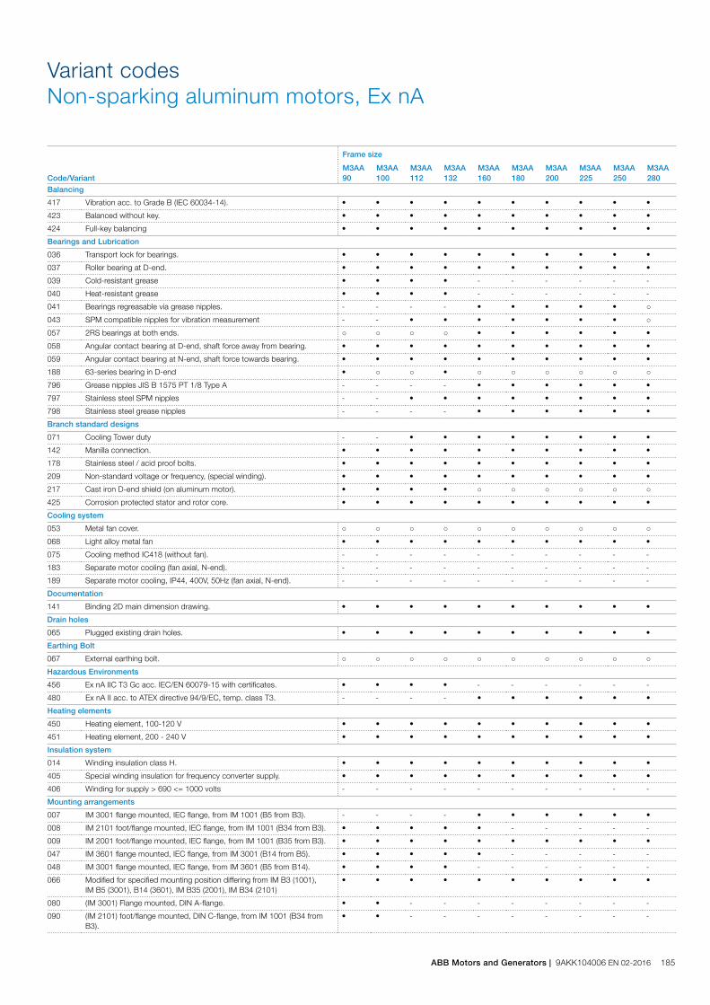
Code/Variant
Frame size
M3AA90
M3AA100
M3AA112
M3AA132
M3AA160
M3AA180
M3AA200
M3AA225
M3AA250
M3AA280
Balancing
417 Vibration acc. to Grade B (IEC 60034-14). • • • • • • • • • •
423 Balanced without key. • • • • • • • • • •
424 Full-key balancing • • • • • • • • • •
Bearings and Lubrication
036 Transport lock for bearings. • • • • • • • • • •
037 Roller bearing at D-end. • • • • • • • • • •
039 Cold-resistant grease • • • • - - - - - -
040 Heat-resistant grease • • • • - - - - - -
041 Bearings regreasable via grease nipples. - - - - • • • • • ○
043 SPM compatible nipples for vibration measurement - - • • • • • • • ○
057 2RS bearings at both ends. ○ ○ ○ ○ • • • • • •
058 Angular contact bearing at D-end, shaft force away from bearing. • • • • • • • • • •
059 Angular contact bearing at N-end, shaft force towards bearing. • • • • • • • • • •
188 63-series bearing in D-end • ○ ○ • ○ ○ ○ ○ ○ ○
796 Grease nipples JIS B 1575 PT 1/8 Type A - - - - • • • • • •
797 Stainless steel SPM nipples - - • • • • • • • •
798 Stainless steel grease nipples - - - - • • • • • •
Branch standard designs
071 Cooling Tower duty - - • • • • • • • •
142 Manilla connection. • • • • • • • • • •
178 Stainless steel / acid proof bolts. • • • • • • • • • •
209 Non-standard voltage or frequency, (special winding). • • • • • • • • • •
217 Cast iron D-end shield (on aluminum motor). • • • • ○ ○ ○ ○ ○ ○
425 Corrosion protected stator and rotor core. • • • • • • • • • •
Cooling system
053 Metal fan cover. ○ ○ ○ ○ ○ ○ ○ ○ ○ ○
068 Light alloy metal fan • • • • • • • • • •
075 Cooling method IC418 (without fan). - - - - - - - - - -
183 Separate motor cooling (fan axial, N-end). - - - - - - - - - -
189 Separate motor cooling, IP44, 400V, 50Hz (fan axial, N-end). - - - - - - - - - -
Documentation
141 Binding 2D main dimension drawing. • • • • • • • • • •
Drain holes
065 Plugged existing drain holes. • • • • • • • • • •
Earthing Bolt
067 External earthing bolt. ○ ○ ○ ○ ○ ○ ○ ○ ○ ○
Hazardous Environments
456 Ex nA IIC T3 Gc acc. IEC/EN 60079-15 with certificates. • • • • - - - - - -
480 Ex nA II acc. to ATEX directive 94/9/EC, temp. class T3. - - - - • • • • • •
Heating elements
450 Heating element, 100-120 V • • • • • • • • • •
451 Heating element, 200 - 240 V • • • • • • • • • •
Insulation system
014 Winding insulation class H. • • • • • • • • • •
405 Special winding insulation for frequency converter supply. • • • • • • • • • •
406 Winding for supply > 690 <= 1000 volts - - - - - - - - - -
Mounting arrangements
007 IM 3001 flange mounted, IEC flange, from IM 1001 (B5 from B3). - - - - • • • • • •
008 IM 2101 foot/flange mounted, IEC flange, from IM 1001 (B34 from B3). • • • • • - - - - -
009 IM 2001 foot/flange mounted, IEC flange, from IM 1001 (B35 from B3). • • • • • • • • • •
047 IM 3601 flange mounted, IEC flange, from IM 3001 (B14 from B5). • • • • • - - - - -
048 IM 3001 flange mounted, IEC flange, from IM 3601 (B5 from B14). • • • • - - - - - -
066 Modified for specified mounting position differing from IM B3 (1001), IM B5 (3001), B14 (3601), IM B35 (2001), IM B34 (2101)
• • • • • • • • • •
080 (IM 3001) Flange mounted, DIN A-flange. • • - - - - - - - -
090 (IM 2101) foot/flange mounted, DIN C-flange, from IM 1001 (B34 from B3).
• • - - - - - - - -
Variant codesNon-sparking aluminum motors, Ex nA
ABB Motors and Generators | 9AKK104006 EN 02-2016 185

Code/Variant
Frame size
M3AA90
M3AA100
M3AA112
M3AA132
M3AA160
M3AA180
M3AA200
M3AA225
M3AA250
M3AA280
091 (IM 2001) foot/flange mounted, DIN A-flange, from IM 1001 (B35 from B3).
• • - - - - - - - -
093 IM 3601 flange mounted, IEC flange, from IM 1001 (B14 from B3). • • • - - - - - - -
200 Flange ring holder. • • • • - - - - - -
218 Flange ring FT 85. • - - - - - - - - -
219 Flange ring FT 100. • - - - - - - - - -
220 Flange ring FF 100. • - - - - - - - - -
223 Flange ring FF 115. • - - - - - - - - -
224 Flange ring FT 115. • - - - - - - - - -
226 Flange ring FF 130. • • • - - - - - - -
227 Flange ring FT 130. • • • - - - - - - -
229 Flange FT 130. - • • - - - - - - -
233 Flange ring FF 165. • • • - - - - - - -
234 Flange ring FT 165. • • • - - - - - - -
235 Flange FF 165. • - - - - - - - - -
236 Flange FT 165. - - - • - - - - - -
243 Flange ring FF 215. - - • • - - - - - -
244 Flange ring FT 215. - • • • - - - - - -
245 Flange FF 215. - • • - - - - - - -
253 Flange ring FF 265. - - - • - - - - - -
254 Flange ring FT 265. - - - • - - - - - -
255 Flange FF 265. - - - • - - - - - -
260 Flange FT 115. • - - - - - - - - -
306 IM 1001 foot mounted, from IM 3601 (B3 from B14). • • • • - - - - - -
307 IM 2101 foot/flange mounted, IEC flange, from IM 3601 (B34 from B14). • • • • - - - - - -
308 IM 2001 foot/flange mounted, IEC flange, from IM 3601 (B35 from B14). • • • • - - - - - -
309 IM 1001 foot mounted, from IM 3001 (B3 from B5). • • • • - - - - - -
310 IM 2101 foot/flange mounted, IEC flange, from IM 3001 (B34 from B5). • • • • - - - - - -
311 IM 2001 foot/flange mounted, IEC flange, from IM 3001 (B35 from B5). • • • • - - - - - -
312 IM 1001 foot mounted, from IM 2101 (B3 from B34). • • • • - - - - - -
313 IM 3601 flange mounted, IEC flange, from IM 2101 (B14 from B34). • • • - - - - - - -
314 IM 3001 flange mounted, IEC flange, from IM 2101 (B5 from B34). • • • - - - - - - -
315 IM 2001 foot/flange mounted, IEC flange, from IM 2101 (B35 from B34). • • • • - - - - - -
316 IM 1001 foot mounted, from IM 2001 (B3 from B35). • • • • - - - - - -
317 IM 3601 flange mounted, IEC flange, from IM 2001 (B14 from B35). • • • - - - - - - -
319 IM 2101 foot/flange mounted, IEC flange, from IM 2001 (B34 from B35). • • • • - - - - - -
Painting
114 Special paint color, standard grade • • • • • • • • • •
Protection
005 Protective roof, vertical motor, shaft down. • • • • • • • • • •
072 Radial seal at D-end. Not possible for 2-pole , 280 and 315 frames • • • • • • • • • •
158 Degree of protection IP65. • • • • • • • • • •
211 Weather protected, IP xx W • • • • • • • • • •
403 Degree of protection IP56. • • • • • • • • • •
404 Degree of protection IP56, without fan and fan cover. - - - - - - - - - -
784 Gamma-seal at D-end. ○ ○ ○ ○ • • • • • •
Rating & instruction plates
002 Restamping voltage, frequency and output, continuous duty. • • • • • • • • • •
004 Additional text on std rating plate (max 12 digits on free text line). • • • • • • • • • •
095 Restamping output (maintained voltage, frequency), intermittent duty. • • • • • • • • • •
098 Stainless rating plate. • • • • • • • • • •
135 Mounting of additional identification plate, stainless. • • • • • • • • • -
138 Mounting of additional identification plate, aluminium. • • • • • • • • • •
139 Additional identification plate delivered loose. • • • • • • • • • •
159 Additional plate with text “Made in ....” • • • • • • • • • •
160 Additional rating plate affixed. • • • • • • • • • •
161 Additional rating plate delivered loose. • • • • • • • • • •
163 Frequency converter rating plate. Rating data according to quotation. • • • • • • • • • •
198 Aluminum rating plate. ○ ○ ○ • ○ ○ ○ ○ ○ ○
332 Baldor Catalogue # • • • • • • • • • •
333 Not for use in the USA • • • • • • • • • •
186 9AKK104006 EN 02-2016 | ABB Catalog
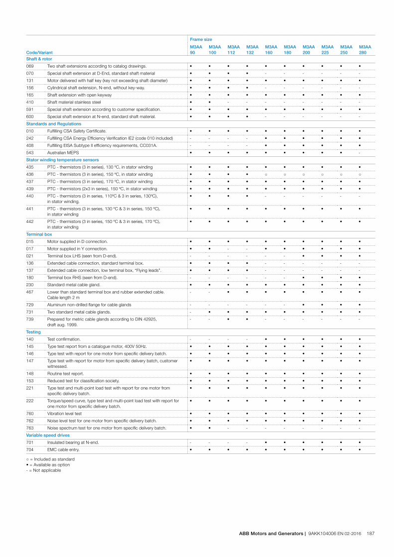
Code/Variant
Frame size
M3AA90
M3AA100
M3AA112
M3AA132
M3AA160
M3AA180
M3AA200
M3AA225
M3AA250
M3AA280
Shaft & rotor
069 Two shaft extensions according to catalog drawings. • • • • • • • • • •
070 Special shaft extension at D-End, standard shaft material • • • • - - - - - -
131 Motor delivered with half key (key not exceeding shaft diameter) • • • • • • • • • •
156 Cylindrical shaft extension, N-end, without key-way. • • • • - - - - - -
165 Shaft extension with open keyway • • • • • • • • • •
410 Shaft material stainless steel • • - - - - - - - -
591 Special shaft extension according to customer specification. • • • • • • • • • •
600 Special shaft extension at N-end, standard shaft material. • • • • - - - - - -
Standards and Regulations
010 Fulfilling CSA Safety Certificate. • • • • • • • • • •
242 Fulfilling CSA Energy Efficiency Verification IE2 (code 010 included) - - - - • • • • • •
408 Fulfilling EISA Subtype II efficiency requirements, CC031A. - - - - • • • • • •
543 Australian MEPS • • • • • • • • • -
Stator winding temperature sensors
435 PTC - thermistors (3 in series), 130 ºC, in stator winding • • • • • • • • • •
436 PTC - thermistors (3 in series), 150 ºC, in stator winding • • • • ○ ○ ○ ○ ○ ○
437 PTC - thermistors (3 in series), 170 ºC, in stator winding • • • • • • • • • •
439 PTC - thermistors (2x3 in series), 150 ºC, in stator winding • • • • • • • • • •
440 PTC - thermistors (3 in series, 110ºC & 3 in series, 130ºC), in stator winding.
• • • • - - - - - -
441 PTC - thermistors (3 in series, 130 ºC & 3 in series, 150 ºC), in stator winding
• • • • • • • • • •
442 PTC - thermistors (3 in series, 150 ºC & 3 in series, 170 ºC), in stator winding
• • • • • • • • • •
Terminal box
015 Motor supplied in D connection. • • • • • • • • • •
017 Motor supplied in Y connection. • • - - • • • • • •
021 Terminal box LHS (seen from D-end). - - - - - - • • • •
136 Extended cable connection, standard terminal box. • • • • - - - - - -
137 Extended cable connection, low terminal box, “Flying leads”. • • • • - - - - - -
180 Terminal box RHS (seen from D-end). - - - - - - • • • •
230 Standard metal cable gland. • • • • • • • • • •
467 Lower than standard terminal box and rubber extended cable. Cable length 2 m
- - • • • • • • • •
729 Aluminum non-drilled flange for cable glands - - - - - - • • • •
731 Two standard metal cable glands. - • • • • • • • • •
739 Prepared for metric cable glands according to DIN 42925, draft aug. 1999.
- - • • - - - - - -
Testing
140 Test confirmation. - - - - • • • • • •
145 Type test report from a catalogue motor, 400V 50Hz. • • • • • • • • • •
146 Type test with report for one motor from specific delivery batch. • • • • • • • • • •
147 Type test with report for motor from specific delivery batch, customer witnessed.
• • • • • • • • • •
148 Routine test report. • • • • • • • • • •
153 Reduced test for classification society. • • • • • • • • • •
221 Type test and multi-point load test with report for one motor from specific delivery batch.
• • • • • • • • • •
222 Torque/speed curve, type test and multi-point load test with report for one motor from specific delivery batch.
• • • • • • • • • •
760 Vibration level test • • • • • • • • • •
762 Noise level test for one motor from specific delivery batch. • • • • • • • • • •
763 Noise spectrum test for one motor from specific delivery batch. • • - - - - - - - -
Variable speed drives
701 Insulated bearing at N-end. - - - - • • • • • •
704 EMC cable entry. • • • • • • • • • •
○ = Included as standard• = Available as option- = Not applicable
ABB Motors and Generators | 9AKK104006 EN 02-2016 187

Motor frameThe motor frame is made of aluminum alloy. Frame size 90-180 have aluminum feet and sizes 200-280 have cast iron feet.
The bearing end shield of sizes 90-132 are made of aluminum, and those of 160 to 280 are made of cast iron.
Motors can be supplied for foot mounting, flange mounting, and combinations of these.
Drain holesNon-sparking motors are provided with drain holes fitted with plugs as standard. The plugs are made of plastic material and delivered in open position.
When mounting arrangement differs from foot mounted IM B3, mention variant code 066 when ordering to ensure the drain plug is mounted in the lowest position.
Mechanical designMotor frame and drain holes
188 9AKK104006 EN 02-2016 | ABB Catalog
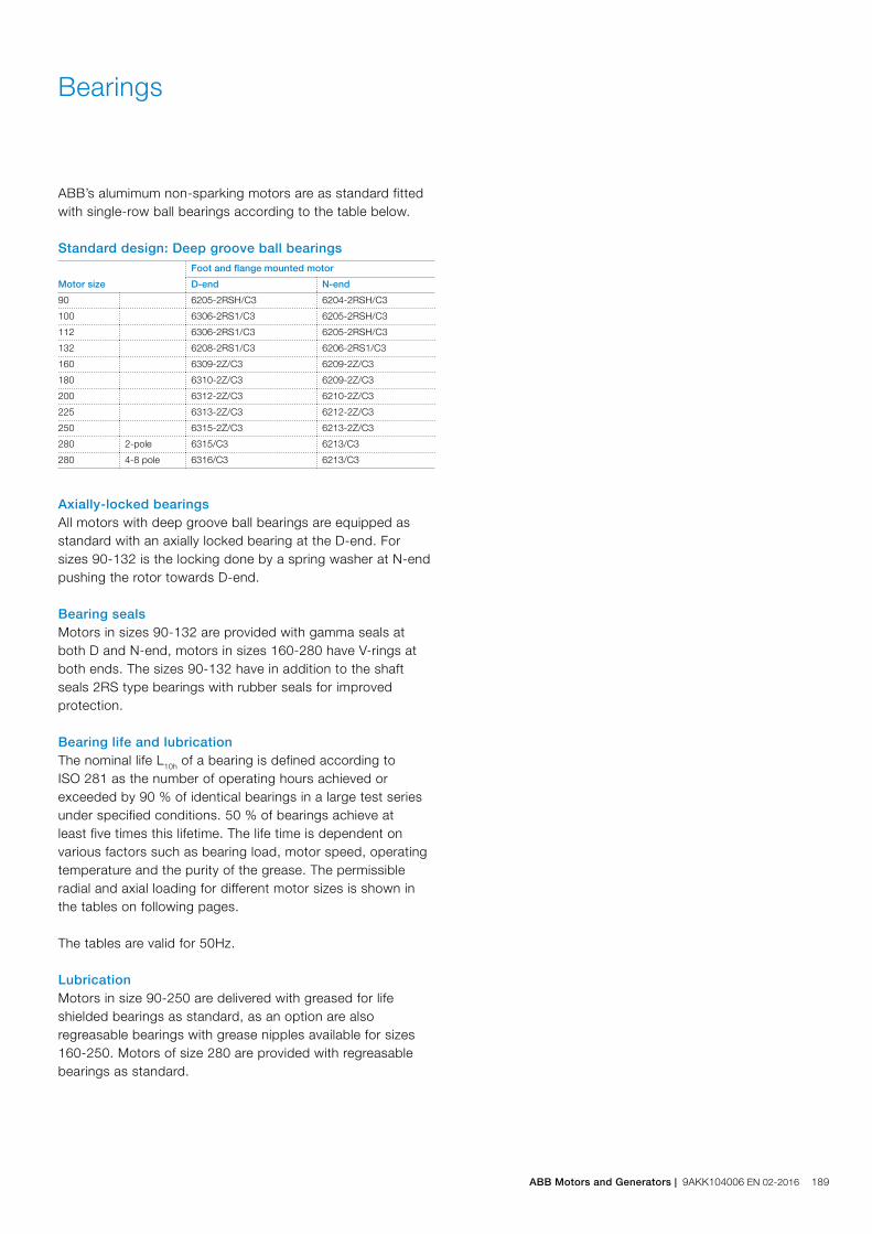
Bearings
ABB’s alumimum non-sparking motors are as standard fitted with single-row ball bearings according to the table below.
Standard design: Deep groove ball bearings
Motor size
Foot and flange mounted motor
D-end N-end
90 6205-2RSH/C3 6204-2RSH/C3
100 6306-2RS1/C3 6205-2RSH/C3
112 6306-2RS1/C3 6205-2RSH/C3
132 6208-2RS1/C3 6206-2RS1/C3
160 6309-2Z/C3 6209-2Z/C3
180 6310-2Z/C3 6209-2Z/C3
200 6312-2Z/C3 6210-2Z/C3
225 6313-2Z/C3 6212-2Z/C3
250 6315-2Z/C3 6213-2Z/C3
280 2-pole 6315/C3 6213/C3
280 4-8 pole 6316/C3 6213/C3
Axially-locked bearingsAll motors with deep groove ball bearings are equipped as standard with an axially locked bearing at the D-end. For sizes 90-132 is the locking done by a spring washer at N-end pushing the rotor towards D-end.
Bearing sealsMotors in sizes 90-132 are provided with gamma seals at both D and N-end, motors in sizes 160-280 have V-rings at both ends. The sizes 90-132 have in addition to the shaft seals 2RS type bearings with rubber seals for improved protection.
Bearing life and lubricationThe nominal life L10h of a bearing is defined according to ISO 281 as the number of operating hours achieved or exceeded by 90 % of identical bearings in a large test series under specified conditions. 50 % of bearings achieve at least five times this lifetime. The life time is dependent on various factors such as bearing load, motor speed, operating temperature and the purity of the grease. The permissible radial and axial loading for different motor sizes is shown in the tables on following pages.
The tables are valid for 50Hz.
LubricationMotors in size 90-250 are delivered with greased for life shielded bearings as standard, as an option are also regreasable bearings with grease nipples available for sizes 160-250. Motors of size 280 are provided with regreasable bearings as standard.
ABB Motors and Generators | 9AKK104006 EN 02-2016 189
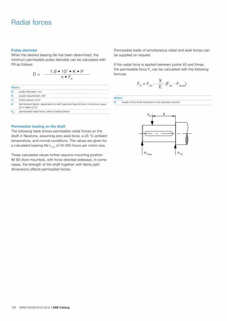
Radial forces
Pulley diameterWhen the desired bearing life has been determined, the minimum permissible pulley diameter can be calculated with FR as follows:
D =1.9 • 107 • K • P
n • FR
Where:
D: pulley diameter, mm
P: power requirement, kW
n: motor speed, r/min.
K: belt tension factor, dependent on belt type and type of duty. A common value for V-belts is 2.5
FR: permissible radial force, refer to tables below.
Permissible loading on the shaftThe following table shows permissible radial forces on the shaft in Newtons, assuming zero axial force, a 25 °C ambient temperature, and normal conditions. The values are given for a calculated bearing life L10h of 40 000 hours per motor size.
These calculated values further assume mounting position IM B3 (foot-mounted), with force directed sideways. In some cases, the strength of the shaft together with flame path dimensions affects permissible forces.
FR = FX0 -
X (FX0 - FXmax)E
Where:
E: length of the shaft extension in the standard version
Permissible loads of simultaneous radial and axial forces can be supplied on request.
If the radial force is applied between points X0 and Xmax, the permissible force FR can be calculated with the following formula:
190 9AKK104006 EN 02-2016 | ABB Catalog

Permissible radial forces, motor sizes 90-132
Motor size Poles
Lengthof shaftextensionE (mm)
Ball bearingsBasic design with deep groove ball bearings
25 000 hours 40 000 hours
FX0 (N) FXmax (N) FX0 (N) FXmax (N)
90 2-8 50 1010 810 1010 810
100 2-8 60 2280 1800 2280 1800
112 2-8 60 2280 1800 2280 1800
132 2-8 80 2120 1610 2120 1610
132 2-8 80 2600 2100 2600 2100
Permissible radial forces, motor sizes 160-280
Motor size Poles
Lengthof shaftextensionE (mm)
Ball bearingsBasic design with deep groove ball bearings
20 000 hours 40 000 hours
FX0(N) FXmax(N) FX0(N) FXmax(N)
160 2 110 4760 3860 4100 3320
4 110 5180 4200 4380 3545
6 110 5160 4180 4360 3540
8 110 6280 4300 5320 4300
180 2 110 6060 4960 5280 1) 4305 1)
4 110 4800 3940 4020 3300
6 110 6280 5140 5280 4380
8 110 6960 5500 5880 4800
200 2 110 7800 6500 6760 2) 5640 2)
4 110 8400 7020 7180 5980
6 110 8960 7480 7600 6340
8 110 10480 8740 8940 7400
225 2 110 8520 7180 7360 3) 6200 3)
4 140 8380 6780 7200 5820
6 140 10 960 8860 9360 7560
8 140 12 100 9780 10 340 8360
250 2 140 10 480 4) 8500 4) 9080 4) 7360 4)
4 140 10 840 8780 9380 7600
6 140 12 600 10 220 10 700 8680
8 140 14 660 11 880 12 540 10 160
280 2 140 6780 5500 5680 4600
4 140 8060 6540 6640 5380
6 140 8980 7280 7360 5960
8 140 9180 7460 7460 6060
1) The maximum lifetime of the grease is 38000 h2) The maximum lifetime of the grease is 27000 h3) The maximum lifetime of the grease is 23000 h4) The maximum lifetime of the grease is 16000 h
ABB Motors and Generators | 9AKK104006 EN 02-2016 191
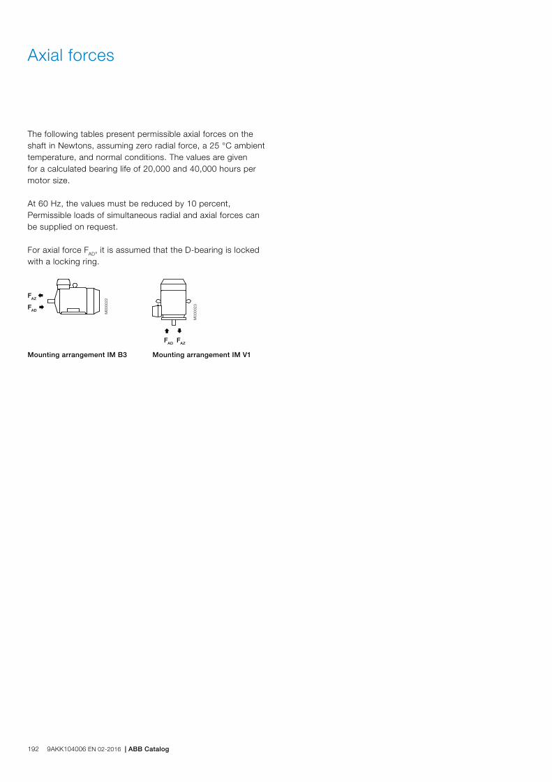
The following tables present permissible axial forces on the shaft in Newtons, assuming zero radial force, a 25 °C ambient temperature, and normal conditions. The values are given for a calculated bearing life of 20,000 and 40,000 hours per motor size.
At 60 Hz, the values must be reduced by 10 percent, Permissible loads of simultaneous radial and axial forces can be supplied on request.
For axial force FAD, it is assumed that the D-bearing is locked with a locking ring.
Axial forces
Ç
FAD
M00
0023
È
FAZ
FAD Æ
M00
0022
FAZ Å
Mounting arrangement IM B3 Mounting arrangement IM V1
192 9AKK104006 EN 02-2016 | ABB Catalog

Permissible axial forces, motor sizes 90-280
Motor size Poles
Mounting arrangement IM B3, deep groove ball bearings Mounting arrangement IM V1, deep groove ball bearings
20 000 hours 40 000 hours 20 000 hours 40 000 hours
FAD (N) FAZ (N) FAD (N) FAZ (N) FAD (N) FAZ (N) FAD (N) FAZ (N)
90 2 885 485 720 320 945 450 775 280
4 1170 650 945 425 1245 600 1020 375
6 1270 870 1005 605 1360 815 1095 550
8 1410 1010 1110 710 1485 960 1185 660
100 2 1620 1120 1280 780 1710 1060 1370 715
4 2065 1565 1615 1115 2180 1485 1735 1035
6 2390 1890 1860 1360 2510 1815 1980 1285
8 2660 2160 2065 1565 2780 2080 2185 1485
112 M, MB 2 1615 1115 1275 775 1725 1040 1385 700
4 2060 1560 1610 1110 2210 1460 1110 1010
6 2385 1885 1860 1360 2540 1785 2010 1260
8 2655 2155 2060 1560 2790 2055 2195 1475
132 M, MA 4 2245 1645 1760 1160 2460 1505 1970 1015
6 2595 1980 2025 1425 2815 1850 2245 1280
8 2875 2270 2240 1640 3130 2115 2490 1470
132 MC 6 2580 1980 2010 1410 2885 1780 2315 1210
132 MBA 4 2235 1635 1750 1150 2495 1465 2010 980
132 S 6 2600 2000 2030 1435 2780 1885 2210 1315
8 2885 2285 2245 1645 3100 2145 2460 1505
132 SB 2 1760 1160 1400 800 1910 1075 1540 705
132 SBB, SC 2 1760 1160 1395 795 1945 1045 1575 670
132 SMB, SMC
2 2210 1610 1740 1140 2435 1470 1950 985
4 2840 2240 2205 1605 3150 2035 2515 1400
132 SMD 4 2830 2200 2230 1595 3195 1995 2560 1355
132 SME 2 2210 1610 1730 1130 2490 1425 2005 940
160 2 4160 4160 3425 3425 4560 3810 3860 3110
4 4740 4740 3920 3920 5260 4310 4440 3490
6 4840 4840 4000 4000 5400 4420 4540 3560
8 5980 5980 4920 4920 6560 5580 5460 4480
180 2 5480 5480 4600 1) 4600 1) 5920 5115 5060 1) 4255 1)
4 4360 4360 3540 3540 5080 3860 4240 3020
6 5980 5980 4940 4630 6000 5445 5600 4385
8 6000 6620 5460 5460 6000 6120 6000 4900
200 2 5000 6880 5000 2) 5700 2) 5000 6350 5000 2) 5230 2)
4 5000 7660 5000 6340 5000 6950 5000 5650
6 5000 8300 5000 6880 5000 7505 5000 6025
8 5000 9880 5000 8160 5000 9215 5000 7435
225 2 5000 7380 5000 3) 6120 3) 5000 6770 5000 3) 5490 3)
4 5000 7600 5000 6220 5000 6795 5000 5475
6 5000 10140 5000 8420 5000 9270 5000 7490
8 5000 11 420 5000 9460 5000 10 595 5000 8535
250 2 6000 4) 9020 4) 6000 4) 7500 4) 6000 4) 8335 4) 6000 4) 6755 4)
4 6000 9800 6000 8040 6000 8820 6000 7120
6 6000 11520 6000 9520 6000 10 275 6000 8235
8 6000 13 700 6000 11 380 6000 12 645 6000 10 205
280 2 5260 5260 4220 4220 6400 4400 5420 3420
4 6500 6500 5160 5160 7920 5400 6640 4120
6 7500 7500 6040 6040 8500 6180 7840 4640
8 7740 7740 6180 6180 8500 6435 7980 4775
1) The maximum lifetime of the grease is 38 000 h2) The maximum lifetime of the grease is 27 000 h3) The maximum lifetime of the grease is 23 000 h4) The maximum lifetime of the grease is 16 000 h
ABB Motors and Generators | 9AKK104006 EN 02-2016 193
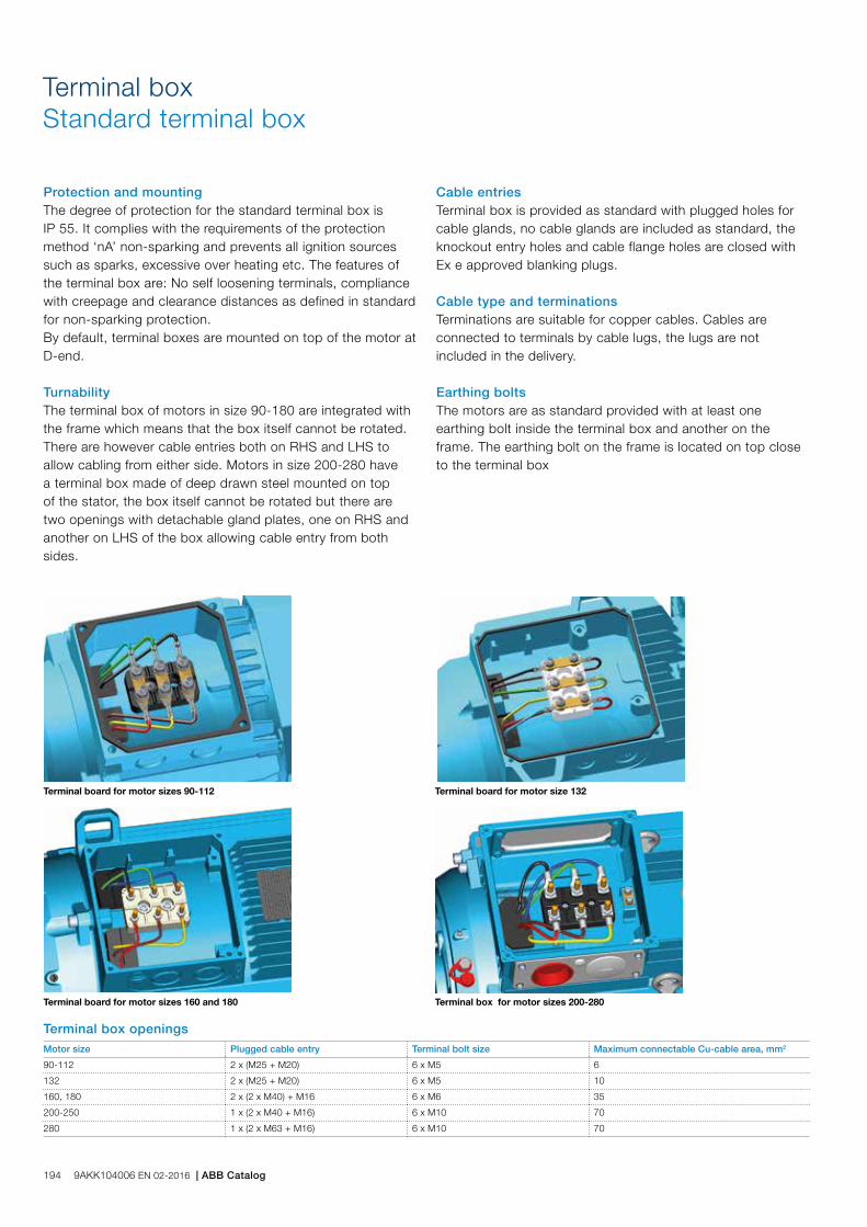
Terminal boxStandard terminal box
Protection and mountingThe degree of protection for the standard terminal box is IP 55. It complies with the requirements of the protection method ‘nA’ non-sparking and prevents all ignition sources such as sparks, excessive over heating etc. The features of the terminal box are: No self loosening terminals, compliance with creepage and clearance distances as defined in standard for non-sparking protection.By default, terminal boxes are mounted on top of the motor at D-end.
TurnabilityThe terminal box of motors in size 90-180 are integrated with the frame which means that the box itself cannot be rotated. There are however cable entries both on RHS and LHS to allow cabling from either side. Motors in size 200-280 have a terminal box made of deep drawn steel mounted on top of the stator, the box itself cannot be rotated but there are two openings with detachable gland plates, one on RHS and another on LHS of the box allowing cable entry from both sides.
Cable entriesTerminal box is provided as standard with plugged holes for cable glands, no cable glands are included as standard, the knockout entry holes and cable flange holes are closed with Ex e approved blanking plugs.
Cable type and terminationsTerminations are suitable for copper cables. Cables are connected to terminals by cable lugs, the lugs are not included in the delivery.
Earthing boltsThe motors are as standard provided with at least one earthing bolt inside the terminal box and another on the frame. The earthing bolt on the frame is located on top close to the terminal box
Terminal board for motor sizes 90-112 Terminal board for motor size 132
Terminal board for motor sizes 160 and 180 Terminal box for motor sizes 200-280
Terminal box openings Motor size Plugged cable entry Terminal bolt size Maximum connectable Cu-cable area, mm2
90-112 2 x (M25 + M20) 6 x M5 6
132 2 x (M25 + M20) 6 x M5 10
160, 180 2 x (2 x M40) + M16 6 x M6 35
200-250 1 x (2 x M40 + M16) 6 x M10 70
280 1 x (2 x M63 + M16) 6 x M10 70
194 9AKK104006 EN 02-2016 | ABB Catalog

Terminal board for motor sizes 90-112 Terminal board for motor size 132
Terminal board for motor sizes 160 and 180 Terminal box for motor sizes 200-280
L
C BB’
E
H
KA
HD
GA
FD
P N
45°
SM
MS
45°
IM 3601, IM B14Motor size LA M N P S T
90 13 115 95 140 M8 3
100 14 130 110 160 M8 3.5
112 14 130 110 160 M8 3.5
132 18 165 165 200 M10 3.5
Motor size
IM 1001, IM B3 AND IM 3001, IM B5 IM 1001, IM B3 IM 3001, IM B5
Dpoles
GApoles
Fpoles
Epoles
L maxpoles A B B' C HD K H M N P S
2 4-8 2 4-8 2 4-8 2 4-8 2 4-8
M3AA 90S 24 24 27 27 8 8 50 50 288 288 30 140 100 - 56 217 10 90 165 130 200 12
90L 24 24 27 27 8 8 50 50 313 313 30 140 125 - 56 217 10 90 165 130 200 12
90LD 24 24 27 27 8 8 50 50 335 335 30 140 125 - 56 217 10 90 165 130 200 12
100 28 28 31 31 8 8 60 60 355 355 35 160 140 - 63 237 12 100 215 180 250 15
100LD 28 28 31 31 8 8 60 60 377 377 35 160 140 - 63 237 12 100 215 180 250 15
112 28 28 31 31 8 8 60 60 397 397 35 190 140 - 70 249 12 112 215 180 250 15
132 1) 38 38 41 41 10 10 80 80 458.5 458.5 50 216 140 178 89 296 12 132 265 230 300 14.5
132 2) 38 38 41 41 10 10 80 80 498.5 498.5 50 216 140 178 89 321 12 132 265 230 300 14.5
160 3) 42 42 45 45 12 12 110 110 584 584 50 254 210 254 108 370 15 160 300 250 350 19
160 4) 42 42 45 45 12 12 110 110 681 681 50 254 210 254 108 370 15 160 300 250 350 19
180 48 48 51.5 51.5 14 14 110 110 726 726 55 279 241 279 121 405 15 180 300 250 350 19
200 55 55 59 59 16 16 110 110 821 821 55 318 267 305 133 532 18 200 350 300 400 19
225 55 60 59 64 16 18 110 140 850 880 60 356 286 311 149 579 18 225 400 350 450 19
250 60 65 64 69 18 18 140 140 884 884 65 406 311 349 168 627 22 250 500 450 550 19
280 65 75 69 79.5 18 20 140 140 884 884 65 457 368 419 190 627 24 280 500 450 550 19
Foot-mounted motor IM 1001, IM B3
Sizes 90 to 200
M00
0267
M00
0268
M00
0270
M00
0269
M00
0271
M00
0272
Flange-mounted motor IM 3001, IM B5
Sizes 225 to 250
Dimension drawingsNon-sparking aluminum motors, Ex nA
Tolerances:
A, B ISO js14
C ± 0.8
D ISO k6 < Ø 50mm
ISO m6 > Ø 50mm
F ISO h9
H -0,5
N ISO j6
In all dimension drawings: The tables give the main dimensions in mm. For detailed drawings please see our web-pages ‘www.abb.com/motors&generators’ or contact ABB.
1) All types except 2)
2) SM_3) MLA 2, MLB 2, MLA 4, MLA 6, MLA 8 and MLB 84) All remining types, i.e. MLC 2, MLD 2, MLE 2, MLB 4, MLC 4, MLD 4 and MLC 85) O = minimum free distance between fan cover air inlet and obstacle preventing air flow
ABB Motors and Generators | 9AKK104006 EN 02-2016 195
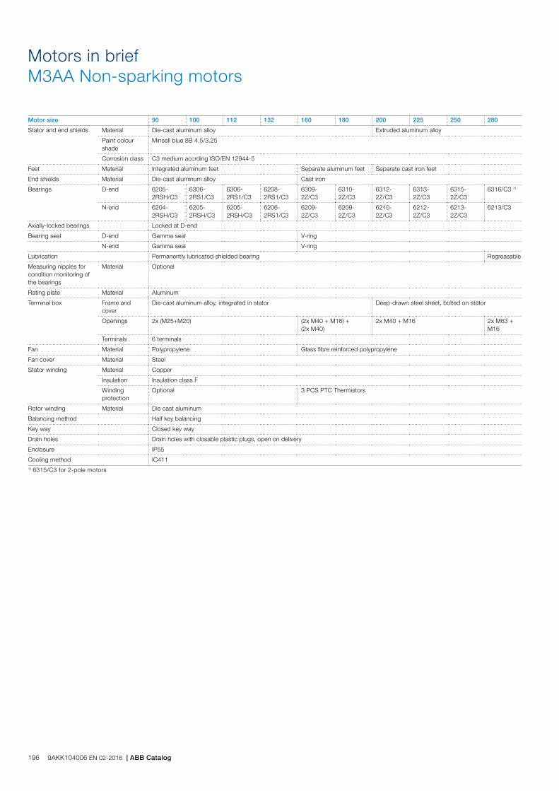
Motors in briefM3AA Non-sparking motors
Motor size 90 100 112 132 160 180 200 225 250 280
Stator and end shields Material Die-cast aluminum alloy Extruded aluminum alloy
Paint colour shade
Minsell blue 8B 4.5/3.25
Corrosion class C3 medium accrding ISO/EN 12944-5
Feet Material Integrated aluminum feet Separate aluminum feet Separate cast iron feet
End shields Material Die-cast aluminum alloy Cast iron
Bearings D-end 6205-2RSH/C3
6306-2RS1/C3
6306-2RS1/C3
6208-2RS1/C3
6309-2Z/C3
6310-2Z/C3
6312-2Z/C3
6313-2Z/C3
6315-2Z/C3
6316/C3 1)
N-end 6204-2RSH/C3
6205-2RSH/C3
6205-2RSH/C3
6206-2RS1/C3
6209-2Z/C3
6209-2Z/C3
6210-2Z/C3
6212-2Z/C3
6213-2Z/C3
6213/C3
Axially-locked bearings Locked at D-end
Bearing seal D-end Gamma seal V-ring
N-end Gamma seal V-ring
Lubrication Permanently lubricated shielded bearing Regreasable
Measuring nipples for condition monitoring of the bearings
Material Optional
Rating plate Material Aluminum
Terminal box Frame and cover
Die-cast aluminum alloy, integrated in stator Deep-drawn steel sheet, bolted on stator
Openings 2x (M25+M20) (2x M40 + M16) + (2x M40)
2x M40 + M16 2x M63 + M16
Terminals 6 terminals
Fan Material Polypropylene Glass fibre reinforced polypropylene
Fan cover Material Steel
Stator winding Material Copper
Insulation Insulation class F
Winding protection
Optional 3 PCS PTC Thermistors
Rotor winding Material Die cast aluminum
Balancing method Half key balancing
Key way Closed key way
Drain holes Drain holes with closable plastic plugs, open on delivery
Enclosure IP55
Cooling method IC4111) 6315/C3 for 2-pole motors
196 9AKK104006 EN 02-2016 | ABB Catalog

Dust ignition protection cast iron motors / Protection by enclosure Ex t IIIB/IIIC T125 °C, Db/DcTotally enclosed squirrel cage three phase low voltage motors, Sizes 71 to 400, 0.25 to 1000 kW
Ordering information 198
Rating plates 199
Technical data 200
IE2 3000 r/min motors 200
IE2 1500 r/min motors 201
IE2 1000 r/min motors 202
IE2 750 r/min motors 203
IE3 3000r/min motors 204
IE3 1500 r/min motors 205
IE3 1000 r/min motors 206
IE3 750 r/min motors 207
Variant codes 208
Mechanical design 213
Motor frame and drain holes 213
Heating elements 214
Bearings 215
Terminal box 227
Dimension drawings 231
Certificate examples 232
Cast iron motors in brief 233
Motor construction 235
ABB Motors and Generators | 9AKK104006 EN 02-2016 197
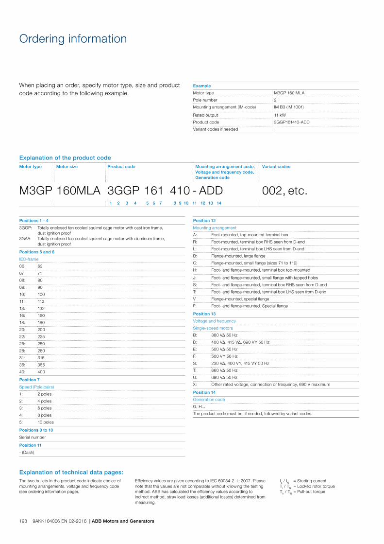
When placing an order, specify motor type, size and product code according to the following example.
Positions 1 - 4
3GGP:
3GAA:
Totally enclosed fan cooled squirrel cage motor with cast iron frame, dust ignition proofTotally enclosed fan cooled squirrel cage motor with aluminum frame, dust ignition proof
Positions 5 and 6
IEC-frame
06 63
07 71
08: 80
09: 90
10: 100
11: 112
13: 132
16: 160
18: 180
20: 200
22: 225
25: 250
28: 280
31: 315
35: 355
40: 400
Position 7
Speed (Pole pairs)
1: 2 poles
2: 4 poles
3: 6 poles
4: 8 poles
5: 10 poles
Positions 8 to 10
Serial number
Position 11
- (Dash)
Ordering information
Position 12
Mounting arrangement
A: Foot-mounted, top-mounted terminal box
R: Foot-mounted, terminal box RHS seen from D-end
L: Foot-mounted, terminal box LHS seen from D-end
B: Flange-mounted, large flange
C: Flange-mounted, small flange (sizes 71 to 112)
H: Foot- and flange-mounted, terminal box top-mounted
J: Foot- and flange-mounted, small flange with tapped holes
S: Foot- and flange-mounted, terminal box RHS seen from D-end
T: Foot- and flange-mounted, terminal box LHS seen from D-end
V Flange-mounted, special flange
F: Foot- and flange-mounted. Special flange
Position 13
Voltage and frequency
Single-speed motors
B: 380 VΔ 50 Hz
D: 400 VΔ, 415 VΔ, 690 VY 50 Hz
E: 500 VΔ 50 Hz
F: 500 VY 50 Hz
S: 230 VΔ, 400 VY, 415 VY 50 Hz
T: 660 VΔ 50 Hz
U: 690 VΔ 50 Hz
X: Other rated voltage, connection or frequency, 690 V maximum
Position 14
Generation code
G, H...
The product code must be, if needed, followed by variant codes.
Explanation of the product codeMotor type Motor size Product code Mounting arrangement code,
Voltage and frequency code,Generation code
Variant codes
M3GP 160MLA 3GGP 161 410 - ADD 002, etc. 1 2 3 4 5 6 7 8 9 10 11 12 13 14
Example
Motor type M3GP 160 MLA
Pole number 2
Mounting arrangement (IM-code) IM B3 (IM 1001)
Rated output 11 kW
Product code 3GGP161410-ADD
Variant codes if needed
198 9AKK104006 EN 02-2016 | ABB Motors and Generators
Is / IN = Starting currentTl / TN = Locked rotor torqueTb / TN = Pull-out torque
The two bullets in the product code indicate choice of mounting arrangements, voltage and frequency code (see ordering information page).
Efficiency values are given according to IEC 60034-2-1; 2007. Please note that the values are not comparable without knowing the testing method. ABB has calculated the efficiency values according to indirect method, stray load losses (additional losses) determined from measuring.
Explanation of technical data pages:

Rating plates
The rating plates are in table form giving values for speed, current and power factor for three voltages for cast iron motors: 400V-415V-690V as standard. Other voltage and frequency combinations are possible and can be ordered with variant codes 002 or 209. Please see Variant code section.
The following information will be shown on the motor rating plate:
− Lowest nominal efficiency at 100 %, 75 % and 50 % rated load
− Efficiency level − Year of manufacture − Type of protection − Apparatus group − Temperature class − Identification number of the certification body − Certificate number: for cast iron motors both ATEX and
IECEx are stamped on the rating plate as standard.
Plates
ABB Motors and Generators | 9AKK104006 EN 02-2016 199
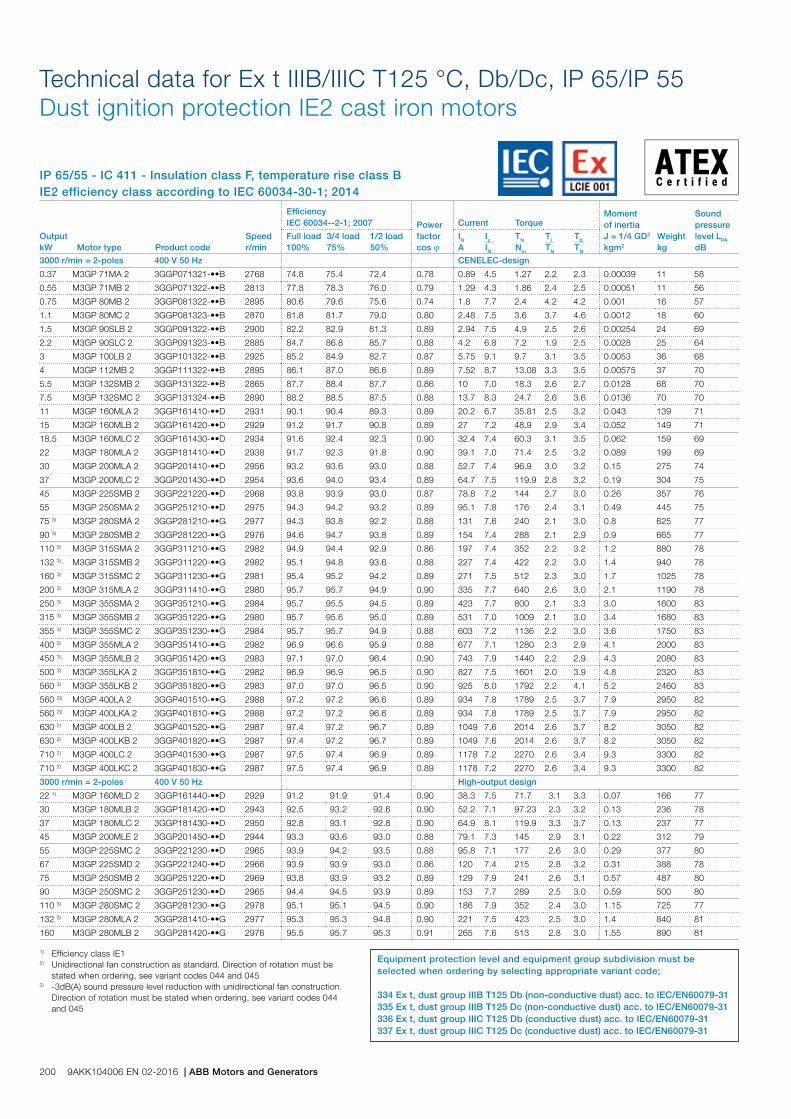
IP 65/55 - IC 411 - Insulation class F, temperature rise class BIE2 efficiency class according to IEC 60034-30-1; 2014
Technical data for Ex t IIIB/IIIC T125 °C, Db/Dc, IP 65/IP 55 Dust ignition protection IE2 cast iron motors
Output kW Motor type Product code
Speed r/min
Efficiency IEC 60034--2-1; 2007 Power
factor cos j
Current Torque Moment of inertiaJ = 1/4 GD2 kgm2
Weight kg
Sound pressure level LPA dB
Full load 100%
3/4 load 75%
1/2 load 50%
IN A
Is IN
TN Nm
Tl TN
Tb TN
3000 r/min = 2-poles 400 V 50 Hz CENELEC-design
0.37 M3GP 71MA 2 3GGP071321-••B 2768 74.8 75.4 72.4 0.78 0.89 4.5 1.27 2.2 2.3 0.00039 11 58
0.55 M3GP 71MB 2 3GGP071322-••B 2813 77.8 78.3 76.0 0.79 1.29 4.3 1.86 2.4 2.5 0.00051 11 56
0.75 M3GP 80MB 2 3GGP081322-••B 2895 80.6 79.6 75.6 0.74 1.8 7.7 2.4 4.2 4.2 0.001 16 57
1.1 M3GP 80MC 2 3GGP081323-••B 2870 81.8 81.7 79.0 0.80 2.48 7.5 3.6 3.7 4.6 0.0012 18 60
1.5 M3GP 90SLB 2 3GGP091322-••B 2900 82.2 82.9 81.3 0.89 2.94 7.5 4.9 2.5 2.6 0.00254 24 69
2.2 M3GP 90SLC 2 3GGP091323-••B 2885 84.7 86.8 85.7 0.88 4.2 6.8 7.2 1.9 2.5 0.0028 25 64
3 M3GP 100LB 2 3GGP101322-••B 2925 85.2 84.9 82.7 0.87 5.75 9.1 9.7 3.1 3.5 0.0053 36 68
4 M3GP 112MB 2 3GGP111322-••B 2895 86.1 87.0 86.6 0.89 7.52 8.7 13.08 3.3 3.5 0.00575 37 70
5.5 M3GP 132SMB 2 3GGP131322-••B 2865 87.7 88.4 87.7 0.86 10 7.0 18.3 2.6 2.7 0.0128 68 70
7.5 M3GP 132SMC 2 3GGP131324-••B 2890 88.2 88.5 87.5 0.88 13.7 8.3 24.7 2.6 3.6 0.0136 70 70
11 M3GP 160MLA 2 3GGP161410-••D 2931 90.1 90.4 89.3 0.89 20.2 6.7 35.81 2.5 3.2 0.043 139 71
15 M3GP 160MLB 2 3GGP161420-••D 2929 91.2 91.7 90.8 0.89 27 7.2 48.9 2.9 3.4 0.052 149 71
18.5 M3GP 160MLC 2 3GGP161430-••D 2934 91.6 92.4 92.3 0.90 32.4 7.4 60.3 3.1 3.5 0.062 159 69
22 M3GP 180MLA 2 3GGP181410-••D 2938 91.7 92.3 91.8 0.90 39.1 7.0 71.4 2.5 3.2 0.089 199 69
30 M3GP 200MLA 2 3GGP201410-••D 2956 93.2 93.6 93.0 0.88 52.7 7.4 96.9 3.0 3.2 0.15 275 74
37 M3GP 200MLC 2 3GGP201430-••D 2954 93.6 94.0 93.4 0.89 64.7 7.5 119.9 2.8 3.2 0.19 304 75
45 M3GP 225SMB 2 3GGP221220-••D 2968 93.8 93.9 93.0 0.87 78.8 7.2 144 2.7 3.0 0.26 357 76
55 M3GP 250SMA 2 3GGP251210-••D 2975 94.3 94.2 93.2 0.89 95.1 7.8 176 2.4 3.1 0.49 445 75
75 3) M3GP 280SMA 2 3GGP281210-••G 2977 94.3 93.8 92.2 0.88 131 7.6 240 2.1 3.0 0.8 625 77
90 3) M3GP 280SMB 2 3GGP281220-••G 2976 94.6 94.7 93.8 0.89 154 7.4 288 2.1 2.9 0.9 665 77
110 3) M3GP 315SMA 2 3GGP311210-••G 2982 94.9 94.4 92.9 0.86 197 7.4 352 2.2 3.2 1.2 880 78
132 3) M3GP 315SMB 2 3GGP311220-••G 2982 95.1 94.8 93.6 0.88 227 7.4 422 2.2 3.0 1.4 940 78
160 3) M3GP 315SMC 2 3GGP311230-••G 2981 95.4 95.2 94.2 0.89 271 7.5 512 2.3 3.0 1.7 1025 78
200 3) M3GP 315MLA 2 3GGP311410-••G 2980 95.7 95.7 94.9 0.90 335 7.7 640 2.6 3.0 2.1 1190 78
250 3) M3GP 355SMA 2 3GGP351210-••G 2984 95.7 95.5 94.5 0.89 423 7.7 800 2.1 3.3 3.0 1600 83
315 3) M3GP 355SMB 2 3GGP351220-••G 2980 95.7 95.6 95.0 0.89 531 7.0 1009 2.1 3.0 3.4 1680 83
355 3) M3GP 355SMC 2 3GGP351230-••G 2984 95.7 95.7 94.9 0.88 603 7.2 1136 2.2 3.0 3.6 1750 83
400 3) M3GP 355MLA 2 3GGP351410-••G 2982 96.9 96.6 95.9 0.88 677 7.1 1280 2.3 2.9 4.1 2000 83
450 3) M3GP 355MLB 2 3GGP351420-••G 2983 97.1 97.0 96.4 0.90 743 7.9 1440 2.2 2.9 4.3 2080 83
500 3) M3GP 355LKA 2 3GGP351810-••G 2982 96.9 96.9 96.5 0.90 827 7.5 1601 2.0 3.9 4.8 2320 83
560 3) M3GP 355LKB 2 3GGP351820-••G 2983 97.0 97.0 96.5 0.90 925 8.0 1792 2.2 4.1 5.2 2460 83
560 2)) M3GP 400LA 2 3GGP401510-••G 2988 97.2 97.2 96.6 0.89 934 7.8 1789 2.5 3.7 7.9 2950 82
560 2)) M3GP 400LKA 2 3GGP401810-••G 2988 97.2 97.2 96.6 0.89 934 7.8 1789 2.5 3.7 7.9 2950 82
630 2) M3GP 400LB 2 3GGP401520-••G 2987 97.4 97.2 96.7 0.89 1049 7.6 2014 2.6 3.7 8.2 3050 82
630 2) M3GP 400LKB 2 3GGP401820-••G 2987 97.4 97.2 96.7 0.89 1049 7.6 2014 2.6 3.7 8.2 3050 82
710 2) M3GP 400LC 2 3GGP401530-••G 2987 97.5 97.4 96.9 0.89 1178 7.2 2270 2.6 3.4 9.3 3300 82
710 2) M3GP 400LKC 2 3GGP401830-••G 2987 97.5 97.4 96.9 0.89 1178 7.2 2270 2.6 3.4 9.3 3300 82
3000 r/min = 2-poles 400 V 50 Hz High-output design
22 1) M3GP 160MLD 2 3GGP161440-••D 2929 91.2 91.9 91.4 0.90 38.3 7.5 71.7 3.1 3.3 0.07 166 77
30 M3GP 180MLB 2 3GGP181420-••D 2943 92.5 93.2 92.6 0.90 52.2 7.1 97.23 2.3 3.2 0.13 236 78
37 M3GP 180MLC 2 3GGP181430-••D 2950 92.8 93.1 92.8 0.90 64.9 8.1 119.9 3.3 3.7 0.13 237 77
45 M3GP 200MLE 2 3GGP201450-••D 2944 93.3 93.6 93.0 0.88 79.1 7.3 145 2.9 3.1 0.22 312 79
55 M3GP 225SMC 2 3GGP221230-••D 2965 93.9 94.2 93.5 0.88 95.8 7.1 177 2.6 3.0 0.29 377 80
67 M3GP 225SMD 2 3GGP221240-••D 2966 93.9 93.9 93.0 0.86 120 7.4 215 2.8 3.2 0.31 388 78
75 M3GP 250SMB 2 3GGP251220-••D 2969 93.8 93.9 93.2 0.89 129 7.9 241 2.6 3.1 0.57 487 80
90 M3GP 250SMC 2 3GGP251230-••D 2965 94.4 94.5 93.9 0.89 153 7.7 289 2.5 3.0 0.59 500 80
110 3) M3GP 280SMC 2 3GGP281230-••G 2978 95.1 95.1 94.5 0.90 186 7.9 352 2.4 3.0 1.15 725 77
132 3) M3GP 280MLA 2 3GGP281410-••G 2977 95.3 95.3 94.8 0.90 221 7.5 423 2.5 3.0 1.4 840 81
160 M3GP 280MLB 2 3GGP281420-••G 2976 95.5 95.7 95.3 0.91 265 7.6 513 2.8 3.0 1.55 890 81
1) Efficiency class IE12) Unidirectional fan construction as standard. Direction of rotation must be stated when ordering, see variant codes 044 and 0453) -3dB(A) sound pressure level reduction with unidirectional fan construction. Direction of rotation must be stated when ordering, see variant codes 044 and 045
Equipment protection level and equipment group subdivision must be selected when ordering by selecting appropriate variant code;
334 Ex t, dust group IIIB T125 Db (non-conductive dust) acc. to IEC/EN60079-31 335 Ex t, dust group IIIB T125 Dc (non-conductive dust) acc. to IEC/EN60079-31336 Ex t, dust group IIIC T125 Db (conductive dust) acc. to IEC/EN60079-31337 Ex t, dust group IIIC T125 Dc (conductive dust) acc. to IEC/EN60079-31
200 9AKK104006 EN 02-2016 | ABB Motors and Generators

IP 65/55 - IC 411 - Insulation class F, temperature rise class BIE2 efficiency class according to IEC 60034-30-1; 2014
Technical data for Ex t IIIB/IIIC T125 °C, Db/Dc, IP 65/IP 55 Dust ignition protection IE2 cast iron motors
1) Efficiency class IE12) Temperature rise class F3) Temp. Rise class F, For 400-415 V 50 Hz (380 V 50 Hz voltage code B)4) For 400-415 V 50 Hz (380 V 50 Hz voltage code B)
Output kW Motor type Product code
Speed r/min
Efficiency IEC 60034--2-1; 2007 Power
factor cos j
Current Torque Moment of inertiaJ = 1/4 GD2 kgm2
Weight kg
Sound pressure level LPA dB
Full load 100%
3/4 load 75%
1/2 load 50%
IN A
Is IN
TN Nm
Tl TN
Tb TN
1500 r/min = 4-poles 400 V 50 Hz CENELEC-design
0.25 1) M3GP 71MA 4 3GGP072321-••B 1365 68.3 70.7 69.6 0.81 0.64 3.5 1.74 1.9 2.0 0.00074 10 45
0.37 1) M3GP 71MB 4 3GGP072322-••B 1380 72.4 74.5 74.7 0.83 0.87 4.6 2.5 1.6 2.1 0.00088 11 45
0.55 1) M3GP 80MA 4 3GGP082321-••B 1415 70.0 69.2 64.7 0.73 1.44 5.6 3.7 2.0 2.8 0.00144 15 45
0.75 M3GP 80MD 4 3GGP082324-••B 1430 81.0 81.0 78.2 0.73 1.82 5.3 5 2.7 3.2 0.00205 17 50
1.1 M3GP 90SLB 4 3GGP092322-••B 1435 83.6 84.1 82.4 0.80 2.36 6.5 7.3 2.4 3.4 0.0044 25 50
1.5 M3GP 90SLD 4 3GGP092325-••B 1430 84.3 85.1 83.9 0.82 3 6.3 10 2.7 3.4 0.0053 27 56
2.2 M3GP 100LC 4 3GGP102323-••B 1450 85.9 85.1 83.4 0.78 4.6 7.7 14.5 2.7 4.1 0.00948 36 56
3 M3GP 100LD 4 3GGP102324-••B 1450 86.8 86.9 85.3 0.79 6.1 7.7 19.8 2.9 3.4 0.011 38 58
4 M3GP 112MB 4 3GGP112322-••B 1440 86.8 87.7 87.4 0.82 7.94 7.0 26.5 2.5 2.9 0.0125 44 59
5.5 M3GP 132SMB 4 3GGP132322-••B 1460 89.0 89.8 88.9 0.80 10.8 6.7 36 2.2 3.2 0.0328 70 67
7.5 M3GP 132SMC 4 3GGP132323-••B 1450 89.3 90.1 90.0 0.81 14.5 7.2 49.4 2.5 3.5 0.0366 73 64
11 M3GP 160MLC 4 3GGP162430-••D 1470 91.2 91.3 90.0 0.82 21.5 8.0 71.5 3.3 3.8 0.096 160 62
15 M3GP 160MLE 4 3GGP162450-••D 1467 92.0 92.3 91.8 0.84 28.5 8.0 97.7 3.3 3.2 0.13 183 61
18.5 M3GP 180MLA 4 3GGP182410-••D 1474 91.6 92.1 91.5 0.83 35.7 7.2 119.9 2.6 3.1 0.19 213 62
22 M3GP 180MLB 4 3GGP182420-••D 1474 92.2 92.5 91.9 0.82 42 7.7 142.3 2.8 3.4 0.23 232 62
30 M3GP 200MLB 4 3GGP202420-••D 1471 92.5 93.2 93.1 0.84 55 7.4 194 3.0 2.8 0.34 306 61
37 M3GP 225SMB 4 3GGP222220-••D 1480 93.6 93.9 93.4 0.85 69 7.6 239 3.2 2.9 0.42 347 67
45 M3GP 225SMC 4 3GGP222230-••D 1477 94.1 94.4 94.3 0.86 78.4 7.6 291 3.2 2.7 0.49 379 67
55 M3GP 250SMA 4 3GGP252210-••D 1479 94.3 94.3 93.6 0.84 100 7.2 355 2.5 3.1 0.72 436 66
75 M3GP 280SMA 4 3GGP282210-••G 1484 94.5 94.7 94.4 0.85 134 6.9 482 2.5 2.8 1.25 625 68
90 M3GP 280SMB 4 3GGP282220-••G 1483 94.7 95.0 94.5 0.85 160 7.2 579 2.5 2.7 1.5 665 68
110 M3GP 315SMA 4 3GGP312210-••G 1487 95.1 95.1 94.3 0.86 194 7.2 706 2.3 2.8 2.3 900 70
132 M3GP 315SMB 4 3GGP312220-••G 1487 95.4 95.4 94.7 0.86 232 7.1 847 2.3 2.7 2.6 960 70
160 M3GP 315SMC 4 3GGP312230-••G 1487 95.3 95.3 94.8 0.85 284 7.2 1027 2.4 2.9 2.9 1000 70
200 M3GP 315MLA 4 3GGP312410-••G 1486 95.6 95.8 95.5 0.86 351 7.2 1285 2.5 2.9 3.5 1160 70
250 M3GP 355SMA 4 3GGP352210-••G 1488 95.9 96.0 95.5 0.85 442 7.1 1604 2.3 2.7 5.9 1610 74
315 M3GP 355SMB 4 3GGP352220-••G 1488 95.9 96.2 95.8 0.86 550 7.3 2021 2.3 2.8 6.9 1780 74
350 4) M3GP 355SMC 4 3GGP352230-••G 1487 95.9 95.9 95.7 0.86 612 6.9 2247 2.4 2.7 7.2 1820 78
400 4) M3GP 355MLA 4 3GGP352410-••G 1489 96.3 96.3 95.9 0.85 705 6.8 2565 2.3 2.6 8.4 2140 78
450 4) M3GP 355MLB 4 3GGP352420-••G 1490 96.8 96.8 96.3 0.86 784 6.9 2884 2.3 2.9 8.4 2140 78
500 M3GP 355LKA 4 3GGP352810-••G 1490 97.0 97.0 96.5 0.86 865 6.8 3204 2.0 3.0 10 2500 78
560 3) M3GP 400LA 4 3GGP402510-••G 1491 96.8 96.8 96.3 0.85 982 7.4 3586 2.4 2.8 15 3200 78
560 3) M3GP 400LKA 4 3GGP402810-••G 1491 96.8 96.8 96.3 0.85 982 7.4 3586 2.4 2.8 15 3200 78
630 4) M3GP 400LB 4 3GGP402520-••G 1491 97.0 97.0 96.5 0.87 1077 7.6 4034 2.2 2.9 16 3300 78
630 4) M3GP 400LKB 4 3GGP402820-••G 1491 97.0 97.0 96.5 0.87 1077 7.6 4034 2.2 2.9 16 3300 78
710 3) M3GP 400LC 4 3GGP402530-••G 1491 97.1 97.1 96.7 0.86 1227 7.6 4547 2.4 3.0 17 3400 78
710 3) M3GP 400LKC 4 3GGP402830-••G 1491 97.1 97.1 96.7 0.86 1227 7.6 4547 2.4 3.0 17 3400 78
800 M3GP 450LA 4 3GGP452510-••G 1491 96.9 96.9 96.4 0.86 1396 7.0 5121 1.3 2.8 23 4050 85
900 M3GP 450LB 4 3GGP452520-••G 1492 97.1 97.0 96.5 0.86 1573 7.0 5761 1.3 2.8 25 4350 85
1000 2) M3GP 450LC 4 3GGP452530-••G 1491 97.2 97.2 96.7 0.86 1724 6.8 6404 1.3 2.7 30 4700 85
1500 r/min = 4-poles 400 V 50 Hz High-output design
18.5 M3GP 160MLF 4 3GGP162460-••H 2929 91.2 91.9 91.4 0.90 38.3 7.5 71.7 3.1 3.3 0.07 166 77
22 1) M3GP 160MLG 4 3GGP162470-••H 2943 92.5 93.2 92.6 0.90 52.2 7.1 97.23 2.3 3.2 0.13 236 78
30 1) M3GP 180MLC 4 3GGP182430-••H 2950 92.8 93.1 92.8 0.90 64.9 8.1 119.9 3.3 3.7 0.13 237 77
37 M3GP 200MLC 4 3GGP202430-••G 2944 93.3 93.6 93.0 0.88 79.1 7.3 145 2.9 3.1 0.22 312 79
55 M3GP 225SMD 4 3GGP222240-••D 2965 93.9 94.2 93.5 0.88 95.8 7.1 177 2.6 3.0 0.29 377 80
60 1) M3GP 225SME 4 3GGP222250-••D 2966 93.9 93.9 93.0 0.86 120 7.4 215 2.8 3.2 0.31 388 78
75 M3GP 250SMB 4 3GGP252220-••D 2969 93.8 93.9 93.2 0.89 129 7.9 241 2.6 3.1 0.57 487 80
86 1) M3GP 250SMC 4 3GGP252230-••D 2965 94.4 94.5 93.9 0.89 153 7.7 289 2.5 3.0 0.59 500 80
110 M3GP 280SMC 4 3GGP282230-••G 2978 95.1 95.1 94.5 0.90 186 7.9 352 2.4 3.0 1.15 725 77
132 M3GP 280MLA 4 3GGP282410-••G 2977 95.3 95.3 94.8 0.90 221 7.5 423 2.5 3.0 1.4 840 81
Equipment protection level and equipment group subdivision must be selected when ordering by selecting appropriate variant code;
334 Ex t, dust group IIIB T125 Db (non-conductive dust) acc. to IEC/EN60079-31 335 Ex t, dust group IIIB T125 Dc (non-conductive dust) acc. to IEC/EN60079-31336 Ex t, dust group IIIC T125 Db (conductive dust) acc. to IEC/EN60079-31337 Ex t, dust group IIIC T125 Dc (conductive dust) acc. to IEC/EN60079-31
ABB Motors and Generators | 9AKK104006 EN 02-2016 201
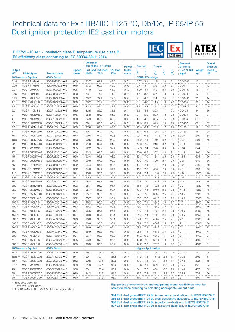
IP 65/55 - IC 411 - Insulation class F, temperature rise class BIE2 efficiency class according to IEC 60034-30-1; 2014
Technical data for Ex t IIIB/IIIC T125 °C, Db/Dc, IP 65/IP 55 Dust ignition protection IE2 cast iron motors
Output kW Motor type Product code
Speed r/min
Efficiency IEC 60034--2-1; 2007 Power
factor cos j
Current Torque Moment of inertiaJ = 1/4 GD2 kgm2
Weight kg
Sound pressure level LPA dB
Full load 100%
3/4 load 75%
1/2 load 50%
IN A
Is IN
TN Nm
Tl TN
Tb TN
1000 r/min = 6-poles 400 V 50 Hz CENELEC-design
0.18 M3GP 71MA 6 3GGP073321-••B 900 63.7 63.8 59.0 0.71 0.57 3.1 1.91 2.0 2.1 0.00089 10 42
0.25 M3GP 71MB 6 3GGP073322-••B 915 67.2 65.5 59.5 0.69 0.77 3.7 2.6 2.6 2.7 0.0011 12 42
0.37 M3GP 80MA 6 3GGP083321-••B 925 71.0 70.0 65.0 0.69 1.09 4.1 3.8 2.4 2.5 0.00187 15 47
0.55 M3GP 80MB 6 3GGP083322-••B 920 73.1 74.2 71.9 0.71 1.51 3.8 5.7 1.8 2.2 0.00239 17 47
0.75 M3GP 90SLC 6 3GGP093323-••B 960 78.7 77.2 72.5 0.58 2.3 4.5 7.4 2.4 3.1 0.00491 25 44
1.1 M3GP 90SLE 6 3GGP093324-••B 930 78.2 78.7 76.5 0.66 3 4.0 11.2 1.9 2.3 0.0054 28 44
1.5 M3GP 100L 6 3GGP103322-••B 950 82.2 83.0 81.6 0.69 3.7 4.3 15 1.5 2.7 0.00873 37 49
2.2 M3GP 112MB 6 3GGP113322-••B 950 82.5 83.7 81.6 0.71 5.5 4.4 22.1 1.7 2.3 0.0125 44 66
3 M3GP 132SMB 6 3GGP133321-••B 975 85.3 84.2 81.2 0.63 8 5.5 29.4 1.8 2.9 0.0334 69 57
4 M3GP 132SMC 6 3GGP133322-••B 960 84.9 85.3 83.9 0.68 10 4.6 39.7 1.5 2.2 0.0334 69 57
5.5 M3GP 132SMF 6 3GGP133324-••B 965 86.1 86.5 85.4 0.71 12.9 5.1 54.4 2.0 2.3 0.0487 86 57
7.5 M3GP 160MLA 6 3GGP163410-••D 965 87.6 88.6 88.3 0.78 15.8 6.4 74.2 1.7 2.9 0.126 181 65
11 M3GP 160MLB 6 3GGP163420-••D 972 90.1 91.0 90.4 0.81 22.1 6.9 108 2.4 3.5 0.126 181 65
15 M3GP 180MLB 6 3GGP183420-••D 973 90.5 91.0 90.5 0.82 29.7 6.8 147.3 1.8 3.0 0.25 240 58
18.5 M3GP 200MLA 6 3GGP203410-••D 983 90.5 90.9 90.2 0.82 36.2 7.1 179 3.2 3.1 0.37 266 66
22 M3GP 200MLB 6 3GGP203420-••D 983 91.6 92.0 91.5 0.82 42.8 7.5 213 3.2 3.2 0.43 283 61
30 M3GP 225SMB 6 3GGP223220-••D 985 92.2 92.7 92.4 0.82 57.9 7.4 290 3.4 3.0 0.64 344 61
37 M3GP 250SMA 6 3GGP253210-••D 990 93.2 93.7 93.1 0.81 70.6 6.5 357 2.4 3.1 1.16 440 66
45 M3GP 280SMA 6 3GGP283210-••G 990 93.4 93.8 93.5 0.83 83.8 7.0 434 2.5 2.5 1.85 605 66
55 M3GP 280SMB 6 3GGP283220-••G 990 93.8 94.2 93.9 0.84 100 7.0 530 2.7 2.6 2.2 645 66
75 M3GP 315SMA 6 3GGP313210-••G 992 94.4 94.4 93.5 0.82 139 7.4 721 2.4 2.8 3.2 830 70
90 M3GP 315SMB 6 3GGP313220-••G 992 94.8 94.7 94.1 0.84 166 7.5 866 2.4 2.8 4.1 930 70
110 M3GP 315SMC 6 3GGP313230-••G 991 95.0 95.0 94.6 0.83 201 7.4 1059 2.5 2.9 4.9 1000 70
132 M3GP 315MLA 6 3GGP313410-••G 991 95.3 95.4 94.9 0.83 240 7.5 1271 2.7 3.0 5.8 1150 68
160 M3GP 355SMA 6 3GGP353210-••G 993 95.4 95.6 95.2 0.83 291 7.0 1538 2.0 2.6 7.9 1520 75
200 M3GP 355SMB 6 3GGP353220-••G 993 95.7 95.9 95.7 0.83 364 7.2 1923 2.2 2.7 9.7 1680 75
250 M3GP 355SMC 6 3GGP353230-••G 993 95.7 95.8 95.4 0.82 460 7.4 2404 2.6 2.9 11.3 1820 75
315 M3GP 355MLB 6 3GGP353420-••G 992 95.7 96.0 95.5 0.83 570 7.0 3032 2.5 2.7 13.5 2180 75
355 M3GP 355LKA 6 3GGP353810-••G 992 95.7 95.9 95.4 0.81 658 7.6 3417 2.7 2.9 15.5 2500 75
400 3) M3GP 400LA 6 3GGP403510-••G 993 96.2 96.3 95.8 0.82 730 7.1 3846 2.3 2.7 17 2900 76
400 3) M3GP 400LKA 6 3GGP403810-••G 993 96.2 96.3 95.8 0.82 730 7.1 3846 2.3 2.7 17 2900 76
450 3) M3GP 400LB 6 3GGP403520-••G 994 96.6 96.6 96.1 0.82 819 7.4 4323 2.4 2.8 20.5 3150 76
450 3) M3GP 400LKB 6 3GGP403820-••G 994 96.6 96.6 96.1 0.82 819 7.4 4323 2.4 2.8 20.5 3150 76
500 3) M3GP 400LC 6 3GGP403530-••G 993 96.6 96.5 96.1 0.83 891 7.2 4809 2.5 2.7 22 3300 76
500 3) M3GP 400LKC 6 3GGP403830-••G 993 96.6 96.5 96.1 0.83 891 7.2 4809 2.5 2.7 22 3300 76
560 3) M3GP 400LD 6 3GGP403540-••G 993 96.9 96.9 96.4 0.85 984 7.4 5386 2.4 2.8 24 3400 77
560 M3GP 400LKD 6 3GGP403840-••G 993 96.9 96.9 96.4 0.85 984 7.4 5386 2.4 2.8 24 3400 77
630 M3GP 450LA 6 3GGP453510-••G 994 96.7 96.7 96.3 0.84 1127 6.5 6053 1.1 2.5 31 4150 81
710 M3GP 450LB 6 3GGP453520-••G 995 96.9 97.0 96.5 0.85 1244 7.0 6814 1.3 2.5 37 4500 81
800 2) M3GP 450LC 6 3GGP453530-••G 995 96.9 96.9 96.4 0.84 1415 7.2 7677 1.3 2.7 41 4800 81
1000 r/min = 6-poles 400 V 50 Hz High-output design
14 1) M3GP 160MLC 6 3GGP163430-••D 969 89.2 89.5 88.5 0.75 30.1 7.5 138 2.8 4.0 0.126 181 64
18.5 1) 2) M3GP 180MLC 6 3GGP183430-••D 971 90.1 90.1 88.5 0.74 41.2 7.3 181.2 2.5 3.7 0.25 240 61
30 1) M3GP 200MLC 6 3GGP203430-••D 983 90.6 90.8 89.6 0.81 59.3 7.5 291 3.5 3.4 0.49 302 65
37 1) M3GP 225SMC 6 3GGP223230-••D 983 91.8 92.1 92.2 0.83 69.6 7.1 359 3.0 2.8 0.75 371 64
45 M3GP 250SMB 6 3GGP253220-••D 986 93.1 93.4 93.2 0.84 84 7.2 435 3.3 2.8 1.49 487 65
75 M3GP 280SMC 6 3GGP283230-••G 990 94.2 94.7 94.5 0.84 137 7.3 723 2.8 2.7 2.85 725 66
90 M3GP 280MLA 6 3GGP283410-••G 990 94.1 94.3 93.7 0.81 170 7.1 868 2.4 2.5 3.1 840 70
1) Efficiency class IE12) Temperature rise class F3) For 400-415 V 50 Hz (380 V 50 Hz voltage code B)
Equipment protection level and equipment group subdivision must be selected when ordering by selecting appropriate variant code;
334 Ex t, dust group IIIB T125 Db (non-conductive dust) acc. to IEC/EN60079-31 335 Ex t, dust group IIIB T125 Dc (non-conductive dust) acc. to IEC/EN60079-31336 Ex t, dust group IIIC T125 Db (conductive dust) acc. to IEC/EN60079-31337 Ex t, dust group IIIC T125 Dc (conductive dust) acc. to IEC/EN60079-31
202 9AKK104006 EN 02-2016 | ABB Motors and Generators
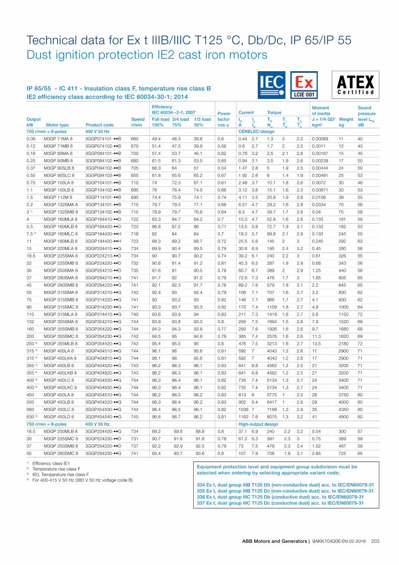
IP 65/55 - IC 411 - Insulation class F, temperature rise class BIE2 efficiency class according to IEC 60034-30-1; 2014
Technical data for Ex t IIIB/IIIC T125 °C, Db/Dc, IP 65/IP 55 Dust ignition protection IE2 cast iron motors
Output kW Motor type Product code
Speed r/min
Efficiency IEC 60034--2-1; 2007 Power
factor cos j
Current Torque Moment of inertiaJ = 1/4 GD2 kgm2
Weight kg
Sound pressure level LPA dB
Full load 100%
3/4 load 75%
1/2 load 50%
IN A
Is IN
TN Nm
Tl TN
Tb TN
750 r/min = 8-poles 400 V 50 Hz CENELEC-design
0.09 M3GP 71MA 8 3GGP074101-••B 660 49.4 46.3 39.6 0.6 0.44 2.7 1.3 2 2.5 0.00089 11 40
0.12 M3GP 71MB 8 3GGP074102-••B 670 51.4 47.5 39.9 0.56 0.6 2.7 1.7 2 2.5 0.0011 12 43
0.18 M3GP 80MA 8 3GGP084101-••B 700 57.4 53.7 46.1 0.62 0.78 3.2 2.5 2.1 2.8 0.00187 15 45
0.25 M3GP 80MB 8 3GGP084102-••B 680 61.5 61.3 53.5 0.65 0.94 3.1 3.5 1.9 2.6 0.00239 17 50
0.37 M3GP 90SLB 8 3GGP094102-••B 705 66.3 64 57 0.54 1.47 2.8 5 1.9 2.5 0.00444 24 50
0.55 M3GP 90SLC 8 3GGP094103-••B 655 61.8 65.6 65.2 0.67 1.92 2.6 8 1.4 1.9 0.00491 25 53
0.75 M3GP 100LA 8 3GGP104101-••B 710 74 72.3 67.1 0.61 2.48 3.7 10.1 1.8 2.6 0.0072 30 46
1.1 M3GP 100LB 8 3GGP104102-••B 695 76 76.4 74.5 0.66 3.12 3.6 15.1 1.6 2.3 0.00871 30 53
1.5 M3GP 112M 8 3GGP114101-••B 690 74.4 75.9 74.1 0.74 4.11 3.5 20.9 1.9 2.6 0.0106 39 55
2.2 M3GP 132SMA 8 3GGP134101-••B 715 79.7 79.5 77.1 0.66 6.51 4.7 29.2 1.6 2.8 0.0334 70 56
3 1) M3GP 132SMB 8 3GGP134102-••B 715 79.9 79.7 76.6 0.64 8.5 4.7 39.7 1.7 2.8 0.04 75 58
4 M3GP 160MLA 8 3GGP164410-••D 722 83.3 84.7 84.2 0.7 10.3 4.7 52.9 1.6 2.6 0.133 181 59
5.5 M3GP 160MLB 8 3GGP164420-••D 723 86.8 87.2 86 0.71 13.5 5.8 72.7 1.9 3.1 0.133 182 53
7.5 3) M3GP 160MLC 8 3GGP164430-••H 718 82 84 84 0.7 19.3 5.7 99.8 2.1 2.9 0.133 245 55
11 M3GP 180MLB 8 3GGP184420-••H 723 88.3 89.2 88.7 0.72 25.5 5.6 145 2 3 0.245 292 63
15 M3GP 200MLA 8 3GGP204410-••G 734 89.9 90.4 89.5 0.79 30.6 6.9 195 2.4 3.2 0.45 280 56
18.5 M3GP 225SMA 8 3GGP224210-••D 734 90 90.7 90.2 0.74 39.2 6.1 240 2.2 3 0.61 326 55
22 M3GP 225SMB 8 3GGP224220-••D 732 90.6 91.4 91.2 0.81 45.3 6.5 287 1.9 2.9 0.68 343 56
30 M3GP 250SMA 8 3GGP254210-••D 735 91.6 91 90.5 0.78 60.7 6.7 389 2 2.9 1.25 440 56
37 M3GP 280SMA 8 3GGP284210-••G 741 91.7 92 91.2 0.79 72.6 7.3 476 1.7 3 1.85 605 65
45 M3GP 280SMB 8 3GGP284220-••G 741 92.1 92.3 91.7 0.78 89.2 7.6 579 1.8 3.1 2.2 645 65
55 M3GP 315SMA 8 3GGP314210-••G 742 92.4 93 92.4 0.79 106 7.1 707 1.6 2.7 3.2 830 62
75 M3GP 315SMB 8 3GGP314220-••G 741 93 93.2 93 0.82 146 7.1 966 1.7 2.7 4.1 930 62
90 M3GP 315SMC 8 3GGP314230-••G 741 93.3 93.7 93.3 0.82 170 7.4 1159 1.8 2.7 4.9 1000 64
110 M3GP 315MLA 8 3GGP314410-••G 740 93.6 93.9 94 0.83 211 7.3 1419 1.8 2.7 5.8 1150 72
132 M3GP 355SMA 8 3GGP354210-••G 744 93.9 93.8 93.3 0.8 256 7.5 1694 1.5 2.6 7.9 1520 69
160 M3GP 355SMB 8 3GGP354220-••G 744 94.3 94.3 93.8 0.77 293 7.6 1926 1.6 2.6 9.7 1680 69
200 M3GP 355SMC 8 3GGP354230-••G 742 94.5 95 94.8 0.79 385 7.4 2576 1.6 2.6 11.3 1820 69
250 4) M3GP 355MLB 8 3GGP354420-••G 743 95.4 95.5 95 0.8 476 7.5 3213 1.6 2.7 13.5 2180 72
315 4) M3GP 400LA 8 3GGP404510-••G 744 96.1 96 95.6 0.81 592 7 4043 1.2 2.6 17 2900 71
315 4) M3GP 400LKA 8 3GGP404810-••G 744 96.1 96 95.6 0.81 592 7 4043 1.2 2.6 17 2900 71
355 4) M3GP 400LB 8 3GGP404520-••G 743 96.2 96.3 96.1 0.83 641 6.8 4562 1.2 2.5 21 3200 71
355 4) M3GP 400LKB 8 3GGP404820-••G 743 96.2 96.3 96.1 0.83 641 6.8 4562 1.2 2.5 21 3200 71
400 4) M3GP 400LC 8 3GGP404530-••G 744 96.3 96.4 96.1 0.82 735 7.4 5134 1.3 2.7 24 3400 71
400 4) M3GP 400LKC 8 3GGP404830-••G 744 96.3 96.4 96.1 0.82 735 7.4 5134 1.3 2.7 24 3400 71
450 M3GP 450LA 8 3GGP454510-••G 744 96.2 96.5 96.2 0.83 813 6 5775 1 2.5 26 3750 80
500 M3GP 450LB 8 3GGP454520-••G 744 96.3 96.4 96.2 0.83 902 6.4 6417 1 2.6 29 4000 80
560 M3GP 450LC 8 3GGP454530-••G 744 96.4 96.5 96.1 0.82 1038 7 7188 1.2 2.9 35 4350 80
630 2) M3GP 450LD 8 3GGP454540-••G 745 96.6 96.7 96.2 0.81 1162 7.6 8075 1.3 3.2 41 4800 80
750 r/min = 8-poles 400 V 50 Hz High-output design
18.5 M3GP 200MLB 8 3GGP204420-••G 734 89.2 89.8 88.8 0.8 37.1 6.9 240 2.2 3.2 0.54 300 57
30 M3GP 225SMC 8 3GGP224230-••D 731 90.7 91.6 91.6 0.78 61.2 6.3 391 2.3 3 0.75 369 59
37 M3GP 250SMB 8 3GGP254220-••D 737 92.2 92.9 92.5 0.79 73 7.5 479 2.3 3.4 1.52 487 59
55 M3GP 280SMC 8 3GGP284230-••G 741 93.4 93.7 93.6 0.8 107 7.9 708 1.9 3.1 2.85 725 65
1) Efficiency class IE12) Temperature rise class F3) IE0, Temperature rise class F4) For 400-415 V 50 Hz (380 V 50 Hz voltage code B)
Equipment protection level and equipment group subdivision must be selected when ordering by selecting appropriate variant code;
334 Ex t, dust group IIIB T125 Db (non-conductive dust) acc. to IEC/EN60079-31 335 Ex t, dust group IIIB T125 Dc (non-conductive dust) acc. to IEC/EN60079-31336 Ex t, dust group IIIC T125 Db (conductive dust) acc. to IEC/EN60079-31337 Ex t, dust group IIIC T125 Dc (conductive dust) acc. to IEC/EN60079-31
ABB Motors and Generators | 9AKK104006 EN 02-2016 203
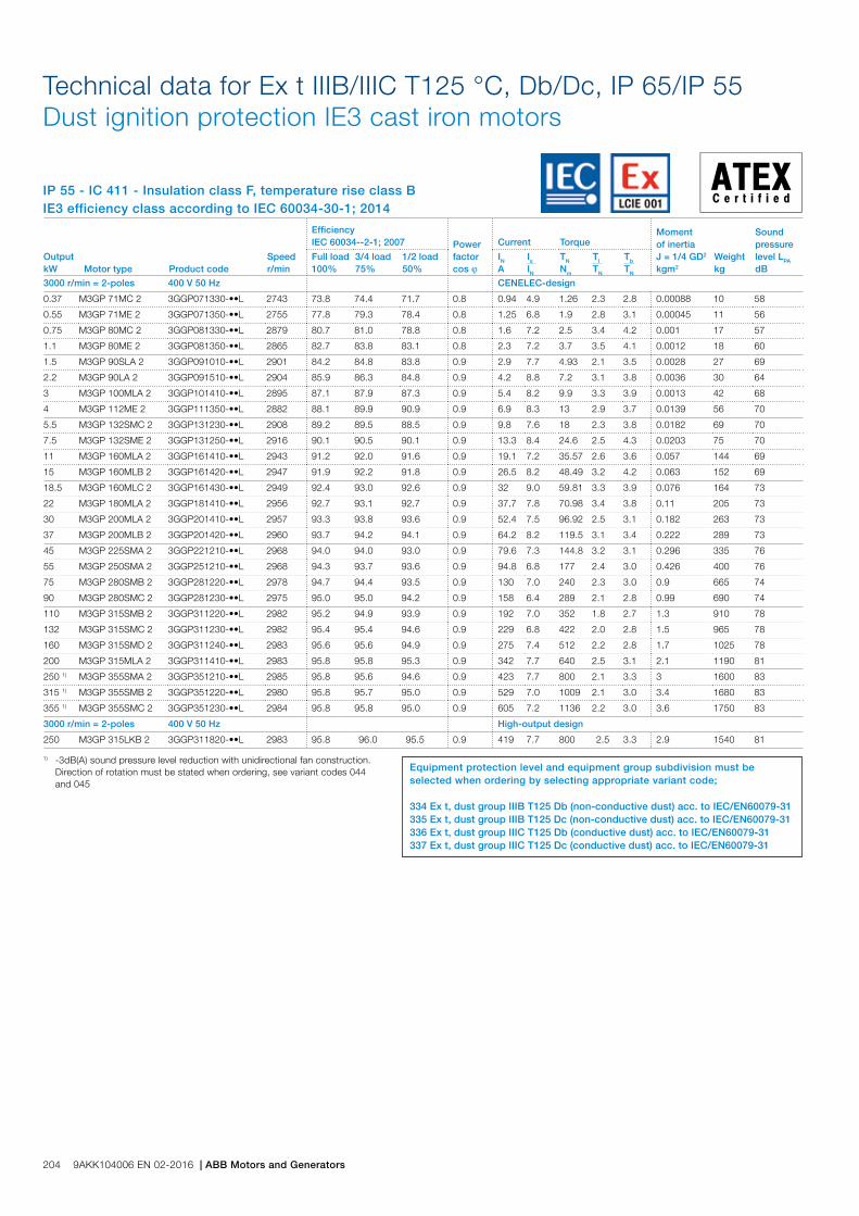
IP 55 - IC 411 - Insulation class F, temperature rise class BIE3 efficiency class according to IEC 60034-30-1; 2014
Technical data for Ex t IIIB/IIIC T125 °C, Db/Dc, IP 65/IP 55Dust ignition protection IE3 cast iron motors
1) -3dB(A) sound pressure level reduction with unidirectional fan construction. Direction of rotation must be stated when ordering, see variant codes 044 and 045
Output kW Motor type Product code
Speed r/min
Efficiency IEC 60034--2-1; 2007 Power
factor cos j
Current Torque Moment of inertiaJ = 1/4 GD2 kgm2
Weight kg
Sound pressure level LPA dB
Full load 100%
3/4 load 75%
1/2 load 50%
IN A
Is IN
TN Nm
Tl TN
Tb TN
3000 r/min = 2-poles 400 V 50 Hz CENELEC-design
0.37 M3GP 71MC 2 3GGP071330-••L 2743 73.8 74.4 71.7 0.8 0.94 4.9 1.26 2.3 2.8 0.00088 10 58
0.55 M3GP 71ME 2 3GGP071350-••L 2755 77.8 79.3 78.4 0.8 1.25 6.8 1.9 2.8 3.1 0.00045 11 56
0.75 M3GP 80MC 2 3GGP081330-••L 2879 80.7 81.0 78.8 0.8 1.6 7.2 2.5 3.4 4.2 0.001 17 57
1.1 M3GP 80ME 2 3GGP081350-••L 2865 82.7 83.8 83.1 0.8 2.3 7.2 3.7 3.5 4.1 0.0012 18 60
1.5 M3GP 90SLA 2 3GGP091010-••L 2901 84.2 84.8 83.8 0.9 2.9 7.7 4.93 2.1 3.5 0.0028 27 69
2.2 M3GP 90LA 2 3GGP091510-••L 2904 85.9 86.3 84.8 0.9 4.2 8.8 7.2 3.1 3.8 0.0036 30 64
3 M3GP 100MLA 2 3GGP101410-••L 2895 87.1 87.9 87.3 0.9 5.4 8.2 9.9 3.3 3.9 0.0013 42 68
4 M3GP 112ME 2 3GGP111350-••L 2882 88.1 89.9 90.9 0.9 6.9 8.3 13 2.9 3.7 0.0139 56 70
5.5 M3GP 132SMC 2 3GGP131230-••L 2908 89.2 89.5 88.5 0.9 9.8 7.6 18 2.3 3.8 0.0182 69 70
7.5 M3GP 132SME 2 3GGP131250-••L 2916 90.1 90.5 90.1 0.9 13.3 8.4 24.6 2.5 4.3 0.0203 75 70
11 M3GP 160MLA 2 3GGP161410-••L 2943 91.2 92.0 91.6 0.9 19.1 7.2 35.57 2.6 3.6 0.057 144 69
15 M3GP 160MLB 2 3GGP161420-••L 2947 91.9 92.2 91.8 0.9 26.5 8.2 48.49 3.2 4.2 0.063 152 69
18.5 M3GP 160MLC 2 3GGP161430-••L 2949 92.4 93.0 92.6 0.9 32 9.0 59.81 3.3 3.9 0.076 164 73
22 M3GP 180MLA 2 3GGP181410-••L 2956 92.7 93.1 92.7 0.9 37.7 7.8 70.98 3.4 3.8 0.11 205 73
30 M3GP 200MLA 2 3GGP201410-••L 2957 93.3 93.8 93.6 0.9 52.4 7.5 96.92 2.5 3.1 0.182 263 73
37 M3GP 200MLB 2 3GGP201420-••L 2960 93.7 94.2 94.1 0.9 64.2 8.2 119.5 3.1 3.4 0.222 289 73
45 M3GP 225SMA 2 3GGP221210-••L 2968 94.0 94.0 93.0 0.9 79.6 7.3 144.8 3.2 3.1 0.296 335 76
55 M3GP 250SMA 2 3GGP251210-••L 2968 94.3 93.7 93.6 0.9 94.8 6.8 177 2.4 3.0 0.426 400 76
75 M3GP 280SMB 2 3GGP281220-••L 2978 94.7 94.4 93.5 0.9 130 7.0 240 2.3 3.0 0.9 665 74
90 M3GP 280SMC 2 3GGP281230-••L 2975 95.0 95.0 94.2 0.9 158 6.4 289 2.1 2.8 0.99 690 74
110 M3GP 315SMB 2 3GGP311220-••L 2982 95.2 94.9 93.9 0.9 192 7.0 352 1.8 2.7 1.3 910 78
132 M3GP 315SMC 2 3GGP311230-••L 2982 95.4 95.4 94.6 0.9 229 6.8 422 2.0 2.8 1.5 965 78
160 M3GP 315SMD 2 3GGP311240-••L 2983 95.6 95.6 94.9 0.9 275 7.4 512 2.2 2.8 1.7 1025 78
200 M3GP 315MLA 2 3GGP311410-••L 2983 95.8 95.8 95.3 0.9 342 7.7 640 2.5 3.1 2.1 1190 81
250 1) M3GP 355SMA 2 3GGP351210-••L 2985 95.8 95.6 94.6 0.9 423 7.7 800 2.1 3.3 3 1600 83
315 1) M3GP 355SMB 2 3GGP351220-••L 2980 95.8 95.7 95.0 0.9 529 7.0 1009 2.1 3.0 3.4 1680 83
355 1) M3GP 355SMC 2 3GGP351230-••L 2984 95.8 95.8 95.0 0.9 605 7.2 1136 2.2 3.0 3.6 1750 83
3000 r/min = 2-poles 400 V 50 Hz High-output design
250 M3GP 315LKB 2 3GGP311820-••L 2983 95.8 96.0 95.5 0.9 419 7.7 800 2.5 3.3 2.9 1540 81
Equipment protection level and equipment group subdivision must be selected when ordering by selecting appropriate variant code;
334 Ex t, dust group IIIB T125 Db (non-conductive dust) acc. to IEC/EN60079-31 335 Ex t, dust group IIIB T125 Dc (non-conductive dust) acc. to IEC/EN60079-31336 Ex t, dust group IIIC T125 Db (conductive dust) acc. to IEC/EN60079-31337 Ex t, dust group IIIC T125 Dc (conductive dust) acc. to IEC/EN60079-31
204 9AKK104006 EN 02-2016 | ABB Motors and Generators
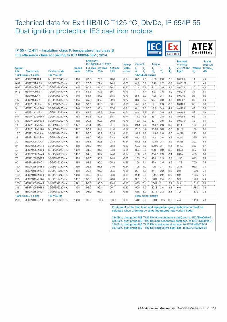
IP 55 - IC 411 - Insulation class F, temperature rise class BIE3 efficiency class according to IEC 60034-30-1; 2014
Technical data for Ex t IIIB/IIIC T125 °C, Db/Dc, IP 65/IP 55Dust ignition protection IE3 cast iron motors
Output kW Motor type Product code
Speed r/min
Efficiency IEC 60034--2-1; 2007 Power
factor cos j
Current Torque Moment of inertiaJ = 1/4 GD2 kgm2
Weight kg
Sound pressure level LPA dB
Full load 100%
3/4 load 75%
1/2 load 50%
IN A
Is IN
TN Nm
Tl TN
Tb TN
3000 r/min = 2-poles 400 V 50 Hz CENELEC-design
0.37 M3GP 71MC 2 3GGP071330-••L 2743 73.8 74.4 71.7 0.8 0.94 4.9 1.26 2.3 2.8 0.00088 10 58
0.55 M3GP 71ME 2 3GGP071350-••L 2755 77.8 79.3 78.4 0.8 1.25 6.8 1.9 2.8 3.1 0.00045 11 56
0.75 M3GP 80MC 2 3GGP081330-••L 2879 80.7 81.0 78.8 0.8 1.6 7.2 2.5 3.4 4.2 0.001 17 57
1.1 M3GP 80ME 2 3GGP081350-••L 2865 82.7 83.8 83.1 0.8 2.3 7.2 3.7 3.5 4.1 0.0012 18 60
1.5 M3GP 90SLA 2 3GGP091010-••L 2901 84.2 84.8 83.8 0.9 2.9 7.7 4.93 2.1 3.5 0.0028 27 69
2.2 M3GP 90LA 2 3GGP091510-••L 2904 85.9 86.3 84.8 0.9 4.2 8.8 7.2 3.1 3.8 0.0036 30 64
3 M3GP 100MLA 2 3GGP101410-••L 2895 87.1 87.9 87.3 0.9 5.4 8.2 9.9 3.3 3.9 0.0013 42 68
4 M3GP 112ME 2 3GGP111350-••L 2882 88.1 89.9 90.9 0.9 6.9 8.3 13 2.9 3.7 0.0139 56 70
5.5 M3GP 132SMC 2 3GGP131230-••L 2908 89.2 89.5 88.5 0.9 9.8 7.6 18 2.3 3.8 0.0182 69 70
7.5 M3GP 132SME 2 3GGP131250-••L 2916 90.1 90.5 90.1 0.9 13.3 8.4 24.6 2.5 4.3 0.0203 75 70
11 M3GP 160MLA 2 3GGP161410-••L 2943 91.2 92.0 91.6 0.9 19.1 7.2 35.57 2.6 3.6 0.057 144 69
15 M3GP 160MLB 2 3GGP161420-••L 2947 91.9 92.2 91.8 0.9 26.5 8.2 48.49 3.2 4.2 0.063 152 69
18.5 M3GP 160MLC 2 3GGP161430-••L 2949 92.4 93.0 92.6 0.9 32 9.0 59.81 3.3 3.9 0.076 164 73
22 M3GP 180MLA 2 3GGP181410-••L 2956 92.7 93.1 92.7 0.9 37.7 7.8 70.98 3.4 3.8 0.11 205 73
30 M3GP 200MLA 2 3GGP201410-••L 2957 93.3 93.8 93.6 0.9 52.4 7.5 96.92 2.5 3.1 0.182 263 73
37 M3GP 200MLB 2 3GGP201420-••L 2960 93.7 94.2 94.1 0.9 64.2 8.2 119.5 3.1 3.4 0.222 289 73
45 M3GP 225SMA 2 3GGP221210-••L 2968 94.0 94.0 93.0 0.9 79.6 7.3 144.8 3.2 3.1 0.296 335 76
55 M3GP 250SMA 2 3GGP251210-••L 2968 94.3 93.7 93.6 0.9 94.8 6.8 177 2.4 3.0 0.426 400 76
75 M3GP 280SMB 2 3GGP281220-••L 2978 94.7 94.4 93.5 0.9 130 7.0 240 2.3 3.0 0.9 665 74
90 M3GP 280SMC 2 3GGP281230-••L 2975 95.0 95.0 94.2 0.9 158 6.4 289 2.1 2.8 0.99 690 74
110 M3GP 315SMB 2 3GGP311220-••L 2982 95.2 94.9 93.9 0.9 192 7.0 352 1.8 2.7 1.3 910 78
132 M3GP 315SMC 2 3GGP311230-••L 2982 95.4 95.4 94.6 0.9 229 6.8 422 2.0 2.8 1.5 965 78
160 M3GP 315SMD 2 3GGP311240-••L 2983 95.6 95.6 94.9 0.9 275 7.4 512 2.2 2.8 1.7 1025 78
200 M3GP 315MLA 2 3GGP311410-••L 2983 95.8 95.8 95.3 0.9 342 7.7 640 2.5 3.1 2.1 1190 81
250 1) M3GP 355SMA 2 3GGP351210-••L 2985 95.8 95.6 94.6 0.9 423 7.7 800 2.1 3.3 3 1600 83
315 1) M3GP 355SMB 2 3GGP351220-••L 2980 95.8 95.7 95.0 0.9 529 7.0 1009 2.1 3.0 3.4 1680 83
355 1) M3GP 355SMC 2 3GGP351230-••L 2984 95.8 95.8 95.0 0.9 605 7.2 1136 2.2 3.0 3.6 1750 83
3000 r/min = 2-poles 400 V 50 Hz High-output design
250 M3GP 315LKB 2 3GGP311820-••L 2983 95.8 96.0 95.5 0.9 419 7.7 800 2.5 3.3 2.9 1540 81
Output kW Motor type Product code
Speed r/min
Efficiency IEC 60034--2-1; 2007 Power
factor cos j
Current Torque Moment of inertiaJ = 1/4 GD2 kgm2
Weight kg
Sound pressure level LPA dB
Full load 100%
3/4 load 75%
1/2 load 50%
IN A
Is IN
TN Nm
Tl TN
Tb TN
1500 r/min = 4-poles 400 V 50 Hz CENELEC-design
0.25 M3GP 71MD 4 3GGP072340-••L 1416 73.5 75.1 73.8 0.8 0.6 4.8 1.68 2.0 2.6 0.0009 11 45
0.37 M3GP 71MLE 4 3GGP072450-••L 1432 77.3 77.4 74.5 0.76 0.9 5.8 2.46 2.7 3.3 0.00122 15 45
0.55 M3GP 80MLC 4 3GGP082430-••L 1444 80.8 81.6 80.1 0.8 1.2 6.7 4 3.0 3.5 0.0028 20 45
0.75 M3GP 80MLE 4 3GGP082450-••L 1448 82.5 82.5 80.1 0.78 1.7 7.4 4.9 3.5 4.0 0.0033 22 50
1.1 M3GP 90LA 4 3GGP092510-••L 1443 84.1 84.6 83.5 0.76 2.4 5.2 7.26 3.4 4.2 0.0049 28 56
1.5 M3GP 90LB 4 3GGP092520-••L 1445 85.3 85.0 82.6 0.77 3.3 5.7 9.9 3.8 4.6 0.0067 32 56
2.2 M3GP 100LA 4 3GGP102510-••L 1448 86.7 89.0 86.1 0.81 4.5 7.5 14 2.3 3.6 0.0109 38 56
3 M3GP 100MLB 4 3GGP102420-••L 1444 87.7 88.4 87.6 0.81 6.1 7.0 19.8 3.3 4.1 0.0121 42 58
4 M3GP 112ME 4 3GGP112350-••L 1453 88.6 88.9 88.0 0.74 8.9 7.8 26 3.5 4.3 0.0188 52 59
5.5 M3GP 132SMB 4 3GGP132220-••L 1463 89.6 89.8 88.7 0.74 11.9 7.6 36 2.8 3.9 0.0295 68 70
7.5 M3GP 132SME 4 3GGP132250-••L 1462 90.4 90.8 90.2 0.76 15.7 7.9 49 3.0 4.0 0.0376 78 64
11 M3GP 160MLA 4 3GGP162410-••L 1477 91.4 91.8 91.1 0.82 21.1 7.6 71.27 2.6 3.3 0.11 160 61
15 M3GP 160MLB 4 3GGP162420-••L 1477 92.1 92.4 91.6 0.82 28.5 8.2 96.99 3.0 3.7 0.135 179 61
18.5 M3GP 180MLA 4 3GGP182410-••L 1481 92.6 93.2 92.9 0.83 34.9 7.2 119.3 2.8 3.0 0.219 215 60
22 M3GP 180MLB 4 3GGP182420-••L 1481 93.0 93.5 93.3 0.82 41.4 6.5 142 3.0 3.2 0.243 229 60
30 M3GP 200MLA 4 3GGP202410-••L 1483 93.6 93.8 93.4 0.84 54.8 7.5 193.2 2.7 3.2 0.385 292 63
37 M3GP 225SMA 4 3GGP222210-••L 1482 93.9 94.1 93.8 0.83 68.9 7.2 238.6 3.1 3.1 0.427 322 67
45 M3GP 225SMB 4 3GGP222220-••L 1482 94.2 94.4 94.0 0.84 82.3 8.0 290 3.2 3.5 0.525 357 66
55 M3GP 250SMA 4 3GGP252210-••L 1482 94.6 94.7 94.0 0.84 100 7.1 354.2 2.9 3.4 0.694 406 68
75 M3GP 280SMB 4 3GGP282220-••L 1485 95.0 95.2 94.8 0.86 133 6.4 483 2.3 2.8 1.38 645 75
90 M3GP 280SMC 4 3GGP282230-••L 1485 95.2 95.5 95.2 0.86 158 7.1 578 2.5 2.9 1.73 700 75
110 M3GP 315SMB 4 3GGP312220-••L 1489 95.4 95.5 94.9 0.84 198 7.0 705 2.1 3.0 2.43 930 71
132 M3GP 315SMC 4 3GGP312230-••L 1488 95.6 95.9 95.5 0.86 231 6.7 847 2.2 2.9 2.9 1000 71
160 M3GP 315SMD 4 3GGP312240-••L 1488 95.8 96.0 95.8 0.85 282 6.9 1026 2.2 3.0 3.2 1065 71
200 M3GP 315MLB 4 3GGP312420-••L 1487 96.0 96.4 96.4 0.86 351 6.8 1284 2.4 3.0 3.9 1220 74
250 M3GP 355SMA 4 3GGP352210-••L 1491 96.0 96.0 95.6 0.86 435 6.4 1601 2.1 2.9 5.9 1610 78
315 M3GP 355SMB 4 3GGP352220-••L 1491 96.0 96.1 95.7 0.85 550 7.3 2018 2.4 3.3 6.9 1780 78
355 M3GP 355SMC 4 3GGP352230-••L 1490 96.0 96.2 95.8 0.86 616 6.3 2273 2.3 2.8 7.2 1820 78
1500 r/min = 4-poles 400 V 50 Hz High-output design
250 M3GP 315LKA 4 3GGP312810-••L 1488 96.0 96.3 96.1 0.85 442 6.9 1604 2.5 3.2 4.4 1410 78
Equipment protection level and equipment group subdivision must be selected when ordering by selecting appropriate variant code;
334 Ex t, dust group IIIB T125 Db (non-conductive dust) acc. to IEC/EN60079-31 335 Ex t, dust group IIIB T125 Dc (non-conductive dust) acc. to IEC/EN60079-31336 Ex t, dust group IIIC T125 Db (conductive dust) acc. to IEC/EN60079-31337 Ex t, dust group IIIC T125 Dc (conductive dust) acc. to IEC/EN60079-31
ABB Motors and Generators | 9AKK104006 EN 02-2016 205

IP 55 - IC 411 - Insulation class F, temperature rise class BIE3 efficiency class according to IEC 60034-30-1; 2014
Technical data for Ex t IIIB/IIIC T125 °C, Db/Dc, IP 65/IP 55Dust ignition protection IE3 cast iron motors
Output kW Motor type Product code
Speed r/min
Efficiency IEC 60034--2-1; 2007 Power
factor cos j
Current Torque Moment of inertiaJ = 1/4 GD2 kgm2
Weight kg
Sound pressure level LPA dB
Full load 100%
3/4 load 75%
1/2 load 50%
IN A
Is IN
TN Nm
Tl TN
Tb TN
1000 r/min = 6-poles 400 V 50 Hz CENELEC-design
0.18 M3GP 71ME 6 3GGP073350-••L 887 63.9 64.3 59.8 0.74 0.57 3.2 1.9 1.9 2.2 0.0009 10 45
0.25 M3GP 80MB 6 3GGP083320-••L 942 68.6 67.0 61.7 0.61 0.82 4.8 2.5 2.7 2.9 0.0019 14 47
0.37 M3GP 80MC 6 3GGP083330-••L 936 73.5 73.9 71.1 0.67 1.06 5.1 3.8 2.6 2.9 0.0028 16 50
0.55 M3GP 80ME 6 3GGP083350-••L 933 77.2 77.9 75.9 0.68 1.52 5.0 5.6 2.7 2.9 0.0035 18 47
0.75 M3GP 90SLD 6 3GGP093040-••L 940 78.9 80.3 79.2 0.75 1.8 4.4 7.57 2.1 2.8 0.0056 29 44
1.1 M3GP 90LF 6 3GGP093560-••L 944 81.0 81.7 80.1 0.75 2.62 4.7 11.1 2.1 2.8 0.0068 33 44
1.5 M3GP 100MLB 6 3GGP103420-••L 960 82.5 82.5 80.1 0.68 3.8 5.4 14.9 2.7 3.4 0.012 41 49
2.2 M3GP 112MJ 6 3GGP113390-••L 962 84.3 85.5 84.7 0.68 5.3 4.2 21.8 1.4 2.3 0.0196 53 66
3 M3GP 132SMB 6 3GGP133220-••L 973 85.6 85.1 82.9 0.62 8 6.6 29.2 2.7 3.8 0.0355 75 57
4 M3GP 132SMF 6 3GGP133260-••L 971 86.8 86.5 84.7 0.62 10.7 6.6 39 2.7 3.8 0.0416 82 57
5.5 M3GP 132SMJ 6 3GGP133290-••L 966 88.0 89.1 88.9 0.73 12.3 4.2 54 1.7 2.7 0.0408 81 57
7.5 M3GP 160MLA 6 3GGP163410-••L 975 89.1 90.0 90.0 0.77 15.7 5.7 73.24 1.4 3.0 0.089 146 59
11 M3GP 160MLB 6 3GGP163420-••L 975 90.3 91.1 91.1 0.78 22.5 6.4 107.5 1.6 3.1 0.138 180 64
15 M3GP 180MLA 6 3GGP183410-••L 979 91.2 91.9 91.6 0.79 30.1 5.2 146.9 1.5 2.7 0.212 212 63
18.5 M3GP 200MLA 6 3GGP203410-••L 989 91.7 91.9 91.2 0.82 35.2 6.5 178.8 2.2 3.2 0.496 272 59
22 M3GP 200MLB 6 3GGP203420-••L 989 92.2 92.4 91.4 0.81 42.4 7.3 212.4 2.6 3.5 0.585 297 59
30 M3GP 225SMA 6 3GGP223210-••L 988 92.9 93.0 92.2 0.77 60.4 7.7 290.6 2.9 3.6 0.724 349 63
37 M3GP 250SMA 6 3GGP253210-••L 990 93.3 93.7 93.5 0.80 71.1 6.5 357 2.4 3.1 1.3 431 58
45 M3GP 280SMB 6 3GGP283220-••L 991 93.7 94.0 93.5 0.84 82 7.4 433 2.7 3.0 1.87 645 72
55 M3GP 280SMC 6 3GGP283230-••L 992 94.1 94.3 93.8 0.86 99 7.5 528 2.8 3.0 2.57 725 71
75 M3GP 315SMB 6 3GGP313220-••L 994 94.6 94.9 94.6 0.84 136 6.8 720 1.8 2.6 4.1 930 75
90 M3GP 315SMC 6 3GGP313230-••L 994 94.9 95.1 94.7 0.84 164 7.2 864 2.0 3.0 4.6 1000 76
110 M3GP 315SMD 6 3GGP313240-••L 994 95.1 95.3 95.0 0.83 200 7.3 1056 2.2 3.1 4.9 1040 75
132 M3GP 315MLB 6 3GGP313420-••L 995 95.4 95.5 95.1 0.82 242 7.3 1266 2.3 3.2 6.3 1200 72
160 M3GP 355SMA 6 3GGP353210-••L 993 95.6 95.8 95.6 0.82 292 6.7 1538 2.5 2.6 7.9 1520 75
200 M3GP 355SMB 6 3GGP353220-••L 993 95.8 96.2 96.1 0.82 365 6.7 1923 2.6 2.5 9.7 1680 75
250 M3GP 355SMC 6 3GGP353230-••L 993 95.8 96.1 95.8 0.81 465 7.7 2404 3.0 3.1 11.3 1820 75
315 M3GP 355MLB 6 3GGP353420-••L 993 95.8 96.1 96.0 0.83 571 6.8 3029 2.6 3.2 13.5 2180 76
355 M3GP 355LKA 6 3GGP353810-••L 993 95.8 96.0 95.9 0.81 653 7.5 3413 2.9 3.2 15.5 2500 76
1000 r/min = 6-poles 400 V 50 Hz High-output design
160 M3GP 315LKA 6 3GGP313810-••L 994 95.6 95.8 95.4 0.81 298 7.5 1535 2.2 3.1 7.3 1410 76
Equipment protection level and equipment group subdivision must be selected when ordering by selecting appropriate variant code;
334 Ex t, dust group IIIB T125 Db (non-conductive dust) acc. to IEC/EN60079-31 335 Ex t, dust group IIIB T125 Dc (non-conductive dust) acc. to IEC/EN60079-31336 Ex t, dust group IIIC T125 Db (conductive dust) acc. to IEC/EN60079-31337 Ex t, dust group IIIC T125 Dc (conductive dust) acc. to IEC/EN60079-31
206 9AKK104006 EN 02-2016 | ABB Motors and Generators
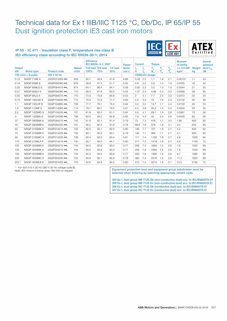
IP 55 - IC 411 - Insulation class F, temperature rise class BIE3 efficiency class according to IEC 60034-30-1; 2014
Technical data for Ex t IIIB/IIIC T125 °C, Db/Dc, IP 65/IP 55Dust ignition protection IE3 cast iron motors
Output kW Motor type Product code
Speed r/min
Efficiency IEC 60034--2-1; 2007 Power
factor cos j
Current Torque Moment of inertiaJ = 1/4 GD2 kgm2
Weight kg
Sound pressure level LPA dB
Full load 100%
3/4 load 75%
1/2 load 50%
IN A
Is IN
TN Nm
Tl TN
Tb TN
750 r/min = 8-poles 400 V 50 Hz CENELEC-design
0.12 M3GP 71ME 8 3GGP074350-••L 659 50.7 48.9 41.9 0.68 0.49 2.5 1.7 1.9 2.1 0.00107 11 43
0.18 M3GP 80MF 8 3GGP084360-••L 679 58.8 57.3 51.7 0.55 0.8 2.2 2.6 1.3 1.9 0.0035 18 45
0.25 M3GP 80MLG 8 3GGP084470-••L 674 64.1 66.4 64.1 0.58 0.92 2.3 3.5 1.3 1.9 0.0044 21 50
0.37 M3GP 90SLF 8 3GGP094060-••L 710 69.3 67.8 62.5 0.54 1.37 3.3 4.96 2.3 3.3 0.0056 28 50
0.55 M3GP 90LG 8 3GGP094570-••L 710 73.0 70.8 64.6 0.53 2 4.1 7.7 2.5 3.2 0.0072 32 53
0.75 M3GP 100LKD 8 3GGP104840-••L 713 75.0 75.3 71.7 0.63 2.2 3.3 10 1.6 2.3 0.0132 45 46
1.1 M3GP 100LKF 8 3GGP104860-••L 708 77.7 78.1 75.5 0.64 3.2 3.5 14.7 1.7 2.4 0.0132 45 53
1.5 M3GP 112MF 8 3GGP114360-••L 714 79.7 80.7 79.5 0.61 4.3 3.9 20.2 1.5 2.3 0.0204 53 55
2.2 M3GP 132SMD 8 3GGP134240-••L 707 81.9 82.4 81.1 0.64 5.9 4.1 29.7 1.9 2.6 0.0361 73 56
3 M3GP 132SMJ 8 3GGP134290-••L 706 83.5 85.2 84.8 0.65 7.9 4.4 40 2.0 2.6 0.0435 83 58
37 M3GP 280SMA 8 3GGP284210-••L 742 91.8 92.1 91.4 0.79 73 7.3 476 1.7 3.0 1.85 605 65
45 M3GP 280SMB 8 3GGP284220-••L 741 92.2 92.4 91.8 0.78 89.6 7.6 579 1.8 3.1 2.2 645 65
55 M3GP 315SMA 8 3GGP314210-••L 742 92.5 93.1 92.5 0.80 106 7.7 707 1.8 2.7 3.2 830 62
75 M3GP 315SMB 8 3GGP314220-••L 740 93.1 93.3 93.1 0.79 146 7.1 966 1.7 2.7 4.1 930 62
90 M3GP 315SMC 8 3GGP314230-••L 739 93.4 93.8 93.4 0.81 171 7.4 1159 1.8 2.7 4.9 1000 64
110 M3GP 315MLA 8 3GGP314410-••L 740 93.7 94.0 94.1 0.80 211 7.3 1419 1.8 2.7 5.8 1150 72
132 M3GP 355SMA 8 3GGP354210-••L 744 94.0 93.9 93.4 0.77 256 7.5 1694 1.5 2.6 7.9 1520 69
132 M3GP 355SMA 8 3GGP354210-••L 744 94.0 93.9 93.4 0.77 256 7.5 1694 1.5 2.6 7.9 1520 69
160 M3GP 355SMB 8 3GGP354220-••L 744 94.3 94.3 93.9 0.77 293 7.6 1926 1.6 2.6 9.7 1680 69
200 M3GP 355SMC 8 3GGP354230-••L 742 94.6 95.1 94.9 0.79 385 7.4 2576 1.6 2.6 11.3 1820 69
250 1) M3GP 355MLB 8 3GGP354420-••L 743 94.6 94.8 94.2 0.80 472 7.5 3213 1.6 2.7 13.5 2180 72
1) For 400-415 V 50 Hz (380 V 50 Hz voltage code B)Note: IE3 motors in frame sizes 160-250 on request Equipment protection level and equipment group subdivision must be
selected when ordering by selecting appropriate variant code;
334 Ex t, dust group IIIB T125 Db (non-conductive dust) acc. to IEC/EN60079-31 335 Ex t, dust group IIIB T125 Dc (non-conductive dust) acc. to IEC/EN60079-31336 Ex t, dust group IIIC T125 Db (conductive dust) acc. to IEC/EN60079-31337 Ex t, dust group IIIC T125 Dc (conductive dust) acc. to IEC/EN60079-31
ABB Motors and Generators | 9AKK104006 EN 02-2016 207

Variant codesDust ignition protection Ex t cast iron motors
Code/Variants
Frame size
71 80 90 100 112 132 160 180 200 225 250 280 315 355 400 450Administration
531 Sea freight packing • • • • • • • • • • • • • • • •
532 Packing of motor in vertical mounting position - - - - - - - - • • • • • - - -
533 Wooden sea freight packing • • • • • • • • • • • • • • • •
590 Mounting of customer supplied part other than coupling. • • • • • • • • • • • • • • • -
Balancing
417 Vibration acc. to Grade B (IEC 60034-14). • • • • • • • • • • • • • • • -
423 Balanced without key. • • • • • • • • • • • • • • • •
424 Full-key balancing • • • • • • • • • • • • • • • •
Bearings and Lubrication
036 Transport lock for bearings. - - - - - - • • • • • • • • • •
037 Roller bearing at D-end. - - - - - - • • • • • • • • • •
040 Heat-resistant grease - - - - - - • • • • • • • • • •
043 SPM compatible nipples for vibration measurement • • • • • • ○ ○ ○ ○ ○ ○ ○ ○ ○ ○
058 Angular contact bearing at D-end, shaft force away from bearing.
- - - - - - • • • • • • • • • •
059 Angular contact bearing at N-end, shaft force towards bearing.
- - - - - - - - - - - • • • • •
060 Angular contact bearing at D-end, shaft force towards bearing.
- - - - - - - - - - - • • • • •
061 Angular contact bearing at N-end, shaft force away from bearing.
- - - - - - - - - - - • • • • •
107 Pt100 2-wire in bearings. - - - - - - • • • • • • • • • •
128 Double PT100, 2-wire in bearings - - - - - - • • • • • • • • • •
129 Double PT100, 3-wire in bearings - - - - - - • • • • • • • • • •
130 Pt100 3-wire in bearings. - - - - - - • • • • • • • • • •
194 2Z bearings greased for life at both ends. ○ ○ ○ ○ ○ ○ • • • • • - - - - -
433 Outlet grease collector - - - - - - - - - - - • • • • •
506 Nipples for vibration measurement : SKF Marlin Quick Connect stud CMSS-2600-3
- - - - - - • • • • • • • • • •
593 Bearings grease suitable for food and beverage industry. • • • • • • • • • • • • • • • •
654 Provision for vibration sensors (M8x1) - - - - - - • • • • • • • • • •
795 Lubrication information plate - - - - - - • • • • • ○ ○ ○ ○ ○
796 Grease nipples JIS B 1575 PT 1/8 Type A - - - - - - • • • • • • • • • •
797 Stainless steel SPM nipples • • • • • • • • • • • • • • • •
798 Stainless steel grease nipples - - - - - - • • • • • • • • • •
799 Grease nipples flat type DIN 3404, thread M10x1 - - - - - - • • • • • • • • • •
800 Grease nipples JIS B 1575 PT 1/8“ pin type - - - - - - • • • • • • • • • •
Branch standard designs
178 Stainless steel / acid proof bolts. ○ ○ ○ ○ ○ ○ • • • • • • • • • •
204 Jacking bolts for foot mounted motors. - - - - - - • • • • • • • ○ ○ ○
209 Non-standard voltage or frequency, (special winding). • • • • • • • • • • • • • • • •
396 Motor designed for ambient temperature -20 °C to -40 °C, with space heaters (code 450/451 must be added)
• • • • • • • • • • • • • • • •
397 Motor designed for ambient temperature -40 °C to -55 °C, with space heaters (code 450/451 must be added)
- - - - - - • • • • • • • • • •
398 Motor designed for ambient temperature -20 °C to -40 °C • • • • • • • • • • • • • • • •
399 Motor designed for ambient temperature -40 °C to -55 °C - - - - - - • • • • • • • • • •
425 Corrosion protected stator and rotor core. • • • • • • • • • • • • • • • •
524 Special run-out tolerances on flange and shaft for close coupled pump applications.
- - - - • • • • • • • • • • - -
786 Special design shaft upwards (V3, V36, V6) for outdoor mounting.
- • • • • • • • • • • - - - - -
Cooling system
044 Unidirectional fan for reduced noise level. Rotation clockwise seen from D-end. Available only for 2-pole motors.
- - - - - - - - - - - • • • • •
045 Unidirectional fan for reduced noise level. Rotation counter clockwise seen from D-end. Available only for 2-pole motors.
- - - - - - - - - - - • • • • •
068 Light alloy metal fan • • • • • • • • • • • • • • • •
208 9AKK104006 EN 02-2016 | ABB Motors and Generators

Code/Variants
Frame size
71 80 90 100 112 132 160 180 200 225 250 280 315 355 400 450183 Separate motor cooling (fan axial, N-end). - - - - - - - - - - - • • • • •
206 Steel fan - - - - - - • • • • • • • • • •
514 Separate motor cooling (fan on top) - - - - - - - - - - - • • • • •
791 Stainless steel fan cover - - - - - - - - - - - • • • • •
Coupling
035 Assembly of customer supplied coupling-half. - - - - - - - - - - - • • • • •
Documentation
141 Binding 2D main dimension drawing. • • • • • • • • • • • • • • • •
374 Binding 2D motor detailed drawing • • • • • • • • • • • • • • • •
722 Rotor dimension drawing (incl. torosional stiffness) • • • • • • • • • • • • • • • •
Drain holes
065 Plugged existing drain holes. • • • • • • • • • • • • • • • •
448 Draining holes with metal plugs. - - - - - - • • • • • • • • • •
Earthing Bolt
525 External earthing bolts on motor feet - • • • • • ○ ○ ○ ○ ○ • • • • •
Hazardous Environments
334 Ex t, Dust group III B T125C Db, IP6X (non-conductive dust) acc. IEC/EN60079-31.
• • • • • • • • • • • • • • • -
335 Ex t, Dust group III B T125C Dc, IP5X (non-conductive dust) acc. IEC/EN60079-31.
• • • • • • • • • • • • • • • -
336 Ex t, Dust group III C T125 Db, IP6X (conductive dust) acc. IEC/EN60079-31.
• • • • • • • • • • • • • • • -
337 Ex t, Dust group III C T125 Dc, IP6X (conductive dust) acc. IEC/EN60079-31.
• • • • • • • • • • • • • • • -
338 Rated for gas or dust, Ex nA IIC T3 Gc / Ex tc IIIB T125C Dc (non-conductive dust), IP5X.
• • • • • • • • • • • • • • • -
339 Rated for gas or dust, Ex nA IIC T3 Gc / Ex tc IIIC T125C Dc (conductive dust), IP6X.
• • • • • • • • • • • • • • • -
516 Ex i approved temperature detectors (Pt100) - - - - - - - - - - - • • • • •
807 CSA design, Class I, Div 2 Group A, B, C, D T3 - - - - - - - - - - - • • • • -
813 Thermistor-based surface temperature protection T4 for frequency convertor duty.
- - - - - - • • • • • • • • • •
814 Ex t (DIP) motors, temperature class T 150C. • • • • • • • • • • • • • • • •
Heating elements
450 Heating element, 100-120 V • • • • • • • • • • • • • • • •
451 Heating element, 200 - 240 V • • • • • • • • • • • • • • • •
Insulation system
014 Winding insulation class H. • • • • • • • • • • • • • • • •
405 Special winding insulation for frequency converter supply. • • • • • • • • • • • • • • • •
Marine
024 Fulfilling Bureau Veritas (BV) requirements, with certificate. • • • • • • • • • • • • • • • •
025 Fulfilling Det Norske Veritas (DNV) requirements, with certificate.
• • • • • • • • • • • • • • • •
026 Fulfilling Lloyds Register of Shipping (LR) requirements, with certificate.
• • • • • • • • • • • • • • • •
027 Fulfilling American Bureau of Shipping (ABS) requirements, with certificate.
• • • • • • • • • • • • • • • •
049 Fulfilling Germanischer Lloyd (GL) requirements, with certificate.
• • • • • • • • • • • • • • • •
050 Fulfilling Registro Italiano Navale (RINA) requirements, with certificate.
• • • • • • • • • • • • • • • •
051 Fulfilling Russian Maritime Register of Shipping (RS) requirements, with certificate.
• • • • • • • • • • • • • • • •
096 Fulfilling Lloyds Register of Shipping (LR) requirements, without certificate (non-essential duty only)
• • • • • • • • • • • • • • • •
186 Fulfilling Det Norske Veritas (DNV) requirements, without certificate (non-essential duty only)
• • • • • • • • • • • • • • • •
481 Fulfilling Nippon Kaiji Kyokai (NK) requirements, with certificate.
• • • • • • • • • • • • • • • •
483 Fulfilling China Classification Societies (CCS) requirements (Beijing), with certificate.
• • • • • • • • • • • • • • • •
484 Fulfilling Korea Register of Shipping (KR) requirements, with certificate.
• • • • • • • • • • • • • • • •
491 Fulfilling Nippon Kaiji Kyokai (NK) requirements, without certificate.
• • • • • • • • • • • • • • • •
492 Fulfilling Registro Italiano Navale (RINA) requirements, without certificate.
• • • • • • • • • • • • • • • •
493 Fulfilling China Classification Societies (CCS) requirements (Beijing), without certificate.
• • • • • • • • • • • • • • • •
ABB Motors and Generators | 9AKK104006 EN 02-2016 209
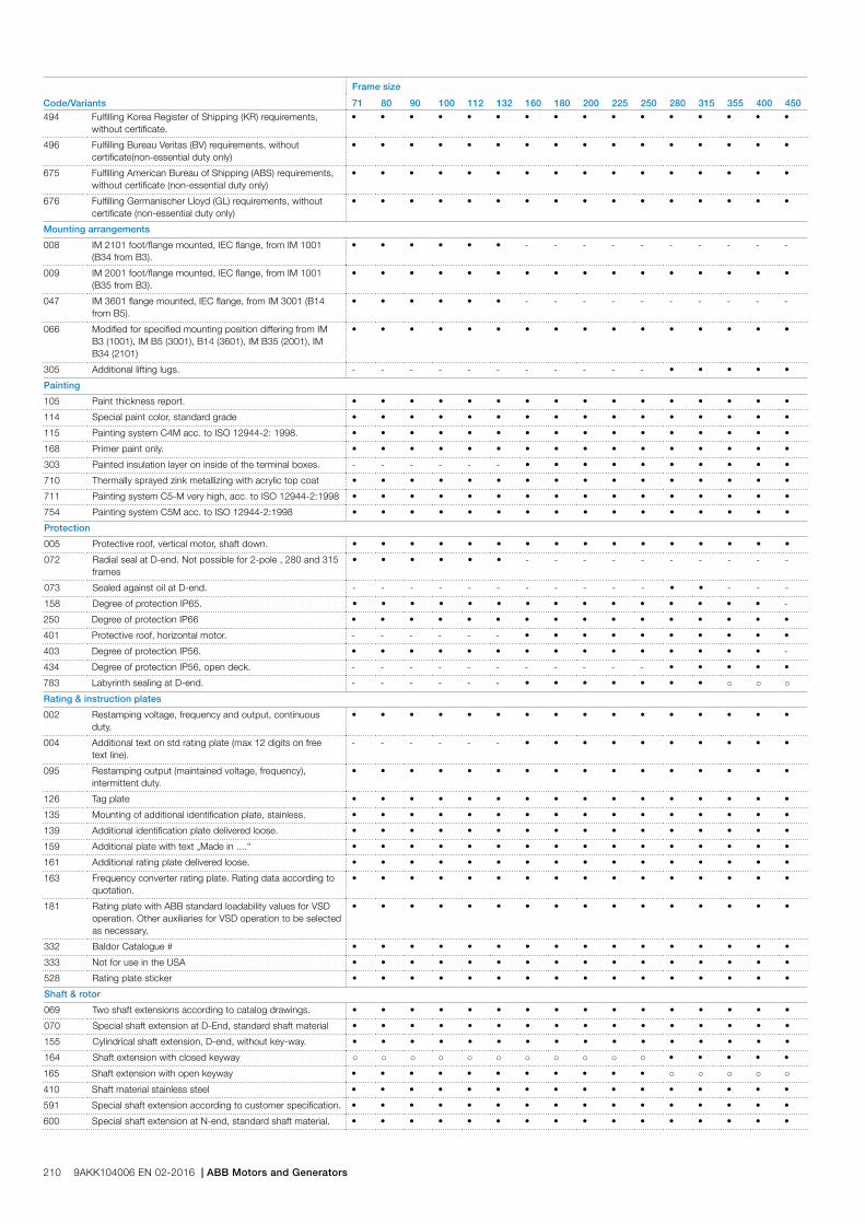
Code/Variants
Frame size
71 80 90 100 112 132 160 180 200 225 250 280 315 355 400 450494 Fulfilling Korea Register of Shipping (KR) requirements,
without certificate.• • • • • • • • • • • • • • • •
496 Fulfilling Bureau Veritas (BV) requirements, without certificate(non-essential duty only)
• • • • • • • • • • • • • • • •
675 Fulfilling American Bureau of Shipping (ABS) requirements, without certificate (non-essential duty only)
• • • • • • • • • • • • • • • •
676 Fulfilling Germanischer Lloyd (GL) requirements, without certificate (non-essential duty only)
• • • • • • • • • • • • • • • •
Mounting arrangements
008 IM 2101 foot/flange mounted, IEC flange, from IM 1001 (B34 from B3).
• • • • • • - - - - - - - - - -
009 IM 2001 foot/flange mounted, IEC flange, from IM 1001 (B35 from B3).
• • • • • • • • • • • • • • • •
047 IM 3601 flange mounted, IEC flange, from IM 3001 (B14 from B5).
• • • • • • - - - - - - - - - -
066 Modified for specified mounting position differing from IM B3 (1001), IM B5 (3001), B14 (3601), IM B35 (2001), IM B34 (2101)
• • • • • • • • • • • • • • • •
305 Additional lifting lugs. - - - - - - - - - - - • • • • •
Painting
105 Paint thickness report. • • • • • • • • • • • • • • • •
114 Special paint color, standard grade • • • • • • • • • • • • • • • •
115 Painting system C4M acc. to ISO 12944-2: 1998. • • • • • • • • • • • • • • • •
168 Primer paint only. • • • • • • • • • • • • • • • •
303 Painted insulation layer on inside of the terminal boxes. - - - - - - • • • • • • • • • •
710 Thermally sprayed zink metallizing with acrylic top coat • • • • • • • • • • • • • • • •
711 Painting system C5-M very high, acc. to ISO 12944-2:1998 • • • • • • • • • • • • • • • •
754 Painting system C5M acc. to ISO 12944-2:1998 • • • • • • • • • • • • • • • •
Protection
005 Protective roof, vertical motor, shaft down. • • • • • • • • • • • • • • • •
072 Radial seal at D-end. Not possible for 2-pole , 280 and 315 frames
• • • • • • - - - - - - - - - -
073 Sealed against oil at D-end. - - - - - - - - - - - • • - - -
158 Degree of protection IP65. • • • • • • • • • • • • • • • -
250 Degree of protection IP66 • • • • • • • • • • • • • • • •
401 Protective roof, horizontal motor. - - - - - - • • • • • • • • • •
403 Degree of protection IP56. • • • • • • • • • • • • • • • -
434 Degree of protection IP56, open deck. - - - - - - - - - - - • • • • •
783 Labyrinth sealing at D-end. - - - - - - • • • • • • • ○ ○ ○
Rating & instruction plates
002 Restamping voltage, frequency and output, continuous duty.
• • • • • • • • • • • • • • • •
004 Additional text on std rating plate (max 12 digits on free text line).
- - - - - - • • • • • • • • • •
095 Restamping output (maintained voltage, frequency), intermittent duty.
• • • • • • • • • • • • • • • •
126 Tag plate • • • • • • • • • • • • • • • •
135 Mounting of additional identification plate, stainless. • • • • • • • • • • • • • • • •
139 Additional identification plate delivered loose. • • • • • • • • • • • • • • • •
159 Additional plate with text „Made in ....“ • • • • • • • • • • • • • • • •
161 Additional rating plate delivered loose. • • • • • • • • • • • • • • • •
163 Frequency converter rating plate. Rating data according to quotation.
• • • • • • • • • • • • • • • •
181 Rating plate with ABB standard loadability values for VSD operation. Other auxiliaries for VSD operation to be selected as necessary.
• • • • • • • • • • • • • • • •
332 Baldor Catalogue # • • • • • • • • • • • • • • • •
333 Not for use in the USA • • • • • • • • • • • • • • • •
528 Rating plate sticker • • • • • • • • • • • • • • • •
Shaft & rotor
069 Two shaft extensions according to catalog drawings. • • • • • • • • • • • • • • • •
070 Special shaft extension at D-End, standard shaft material • • • • • • • • • • • • • • • •
155 Cylindrical shaft extension, D-end, without key-way. • • • • • • • • • • • • • • • •
164 Shaft extension with closed keyway ○ ○ ○ ○ ○ ○ ○ ○ ○ ○ ○ • • • • •
165 Shaft extension with open keyway • • • • • • • • • • • ○ ○ ○ ○ ○
410 Shaft material stainless steel • • • • • • • • • • • • • • • •
591 Special shaft extension according to customer specification. • • • • • • • • • • • • • • • •
600 Special shaft extension at N-end, standard shaft material. • • • • • • • • • • • • • • • •
210 9AKK104006 EN 02-2016 | ABB Motors and Generators

Code/Variants
Frame size
71 80 90 100 112 132 160 180 200 225 250 280 315 355 400 450630 Shaft material certificate 3.1/3.2 according to
EN10204:2004- - - - - • • • • • • • • • • •
Standards and Regulations
248 Design according to Petronas PTS 33.66.05.31-GEN. February 2010.
- - - - - - • • • • • • • • - -
251 Shell DEP 33.66.05.31-GEN. February 2012. • • • • • • • • • • • • • • • •
408 Fulfilling EISA Subtype II efficiency requirements, CC031A. • • • • • - - -
421 VIK design (Verband der Industriellen Energie- und Kraftwirtschaft e.V.).
- - - - - - - - - - - • • • • -
505 VIK design with ABB standard shaft dimensions (Verband der Industriellen Energie- und Kraftwirtschaft e.V.).
- - - - - - - - - - - - • • • -
540 China energy label - - - - - - • • • • • • • • - -
541 Inmetro certification • • • • •
542 NBR design • • - - -
543 Australian MEPS - • • • • • • • • • • • • • - -
547 Certificate of conformity according TR-CU 012/2011 for customs union RU, KZ, BY.
• • • • • • • • • • • • • • • •
782 Fulfilling CQST Certification requirements (China) • • • • • • • • • • • • • • • •
Stator winding temperature sensors
120 KTY 84-130 (1 per phase) in stator winding. - - - - - - • • • • • • • • • •
328 PTC - thermistors (3 in series), 120ºC, in stator winding - - - - - - • • • • • • • • • •
435 PTC - thermistors (3 in series), 130 ºC, in stator winding • • • • • • • • • • • • • • • •
439 PTC - thermistors (2x3 in series), 150 ºC, in stator winding • • • • • • • • • • • • • • • •
441 PTC - thermistors (3 in series, 130 ºC & 3 in series, 150 ºC), in stator winding
• • • • • • • • • • • • • • • •
445 Pt100 2-wire in stator winding, 1 per phase - - - - - - • • • • • • • • • •
446 Pt100 2-wire in stator winding, 2 per phase - - - - - - • • • • • • • • • •
502 Pt100 3-wire in stator winding, 1 per phase - - - - - - • • • • • • • • • •
503 Pt100 3-wire in stator winding, 2 per phase - - - - - - • • • • • • • • • •
511 PTC thermistors (2 x 3 in series), 130 ºC, in stator winding • • • • • • • • • • • • • • • •
Terminal box
019 Larger than standard terminal box. • • • • • • - - - - - • • • • -
021 Terminal box LHS (seen from D-end). - - - - - - • • • • • • • • • -
022 Cable entry LHS (seen from D-end). • • • • • • • • • • • • • • • •
157 Terminal box degree of protection IP65. • • • • • • • • • • • • • • • -
180 Terminal box RHS (seen from D-end). - - - - - - • • • • • • • • • -
230 Standard metal cable gland. • • • • • • • • • • • • • • - -
351 Terminal block turned according to cable entry - - - - - - - - - - - • • - • •
380 Separate terminal box for temperature detectors, std. material
- - - - - - • • • • • • • • • •
400 4 x 90 degr turnable terminal box. • • • • • • ○ ○ ○ ○ ○ ○ ○ - - -
413 Extended cable connection, no terminal box. - - - - - - • • • • • • • • • -
418 Separate terminal box for auxiliaries, standard material. - - - - - - • • • • • • • • • •
447 Top mounted separate terminal box for monitoring equipment.
- - - - - - - - - - - • • • - -
466 Terminal box at N-end. - - - - - - • • • • • • • • • •
468 Cable entry from D-end. - - - - - - • • • • • • • • • -
469 Cable entry from N-end. - - - - - - • • • • • • • • • -
526 Existing cable entries plugged ○ ○ ○ ○ ○ ○ ○ ○ ○ ○ ○ ○ ○ • • •
553 Terminal box degree of protection IP66. • • • • • • • • • • • • • • • -
554 Painted steel flange for cable glands drilled and tapped according to order.
- - - - - - • • • • • • • • • •
555 Aluminum flange for cable glands drilled and tapped according to order.
- - - - - - • • • • • • • • • •
557 Nickel plated cable glands mounted according to order. - • • • • • • • • • • • • • • •
567 Separate terminal box material: cast Iron - - - - - - ○ ○ ○ ○ ○ • • • • •
568 Separate terminal box for heating elements, std. material - - - - - - • • • • • • • • • •
624 Prepared for BSP cable glands. - • • • • • • • • • • • • • • •
727 Stainless steel flange for cable glands drilled and tapped according to order.
- - - - - - • • • • • • • • • •
729 Aluminum non-drilled flange for cable glands - - - - - - • • • • • • • • • •
730 Prepared for NPT cable glands. - - - - - - • • • • • • • • • •
731 Two standard metal cable glands. • • • • • • • • • • • • • • • •
734 Standard cable gland, Ex d IIC, armoured cable. - • • • • • • • • • • • • • • •
735 Standard cable gland, Ex d IIC, non-armoured cable. - • • • • • • • • • • • • • • •
741 Motor equipped with Ex e terminal box (EN 50019). - - - - - - • • • • • • • • • •
743 Painted non-drilled flange in steel for cable glands - - - - - - • • • • • • • • • •
ABB Motors and Generators | 9AKK104006 EN 02-2016 211
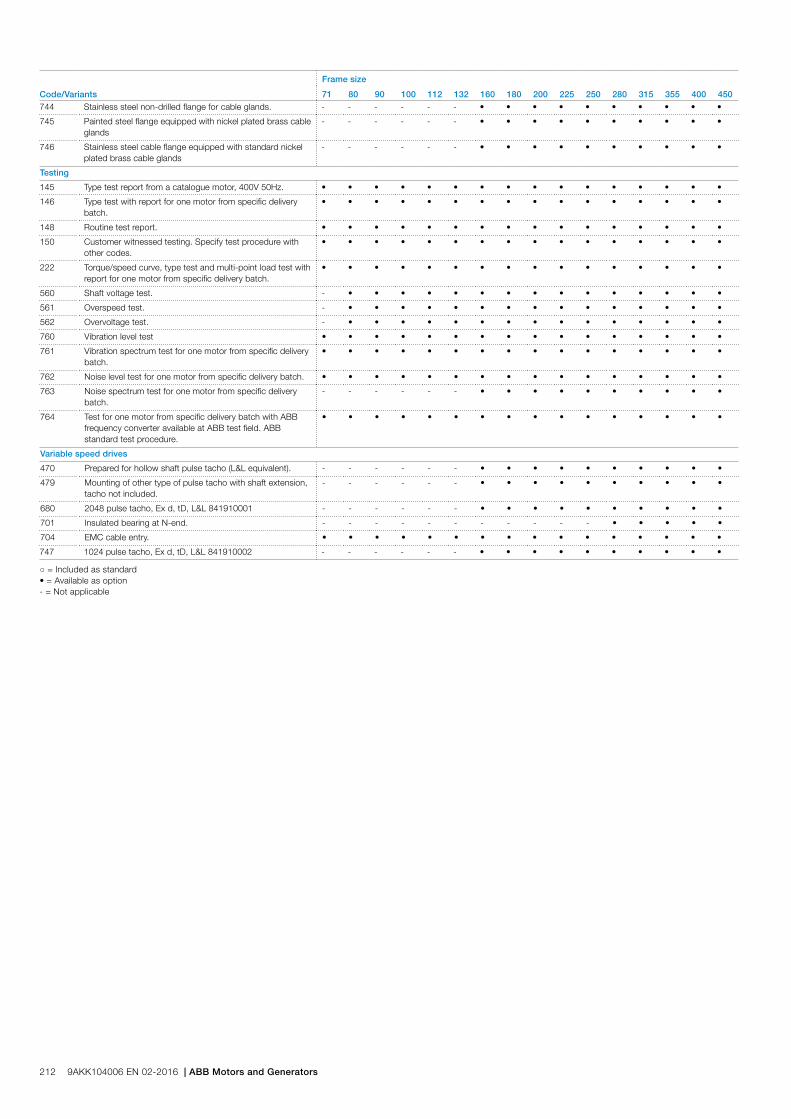
Code/Variants
Frame size
71 80 90 100 112 132 160 180 200 225 250 280 315 355 400 450744 Stainless steel non-drilled flange for cable glands. - - - - - - • • • • • • • • • •
745 Painted steel flange equipped with nickel plated brass cable glands
- - - - - - • • • • • • • • • •
746 Stainless steel cable flange equipped with standard nickel plated brass cable glands
- - - - - - • • • • • • • • • •
Testing
145 Type test report from a catalogue motor, 400V 50Hz. • • • • • • • • • • • • • • • •
146 Type test with report for one motor from specific delivery batch.
• • • • • • • • • • • • • • • •
148 Routine test report. • • • • • • • • • • • • • • • •
150 Customer witnessed testing. Specify test procedure with other codes.
• • • • • • • • • • • • • • • •
222 Torque/speed curve, type test and multi-point load test with report for one motor from specific delivery batch.
• • • • • • • • • • • • • • • •
560 Shaft voltage test. - • • • • • • • • • • • • • • •
561 Overspeed test. - • • • • • • • • • • • • • • •
562 Overvoltage test. - • • • • • • • • • • • • • • •
760 Vibration level test • • • • • • • • • • • • • • • •
761 Vibration spectrum test for one motor from specific delivery batch.
• • • • • • • • • • • • • • • •
762 Noise level test for one motor from specific delivery batch. • • • • • • • • • • • • • • • •
763 Noise spectrum test for one motor from specific delivery batch.
- - - - - - • • • • • • • • • •
764 Test for one motor from specific delivery batch with ABB frequency converter available at ABB test field. ABB standard test procedure.
• • • • • • • • • • • • • • • •
Variable speed drives
470 Prepared for hollow shaft pulse tacho (L&L equivalent). - - - - - - • • • • • • • • • •
479 Mounting of other type of pulse tacho with shaft extension, tacho not included.
- - - - - - • • • • • • • • • •
680 2048 pulse tacho, Ex d, tD, L&L 841910001 - - - - - - • • • • • • • • • •
701 Insulated bearing at N-end. - - - - - - - - - - - • • • • •
704 EMC cable entry. • • • • • • • • • • • • • • • •
747 1024 pulse tacho, Ex d, tD, L&L 841910002 - - - - - - • • • • • • • • • •
○ = Included as standard• = Available as option- = Not applicable
212 9AKK104006 EN 02-2016 | ABB Motors and Generators
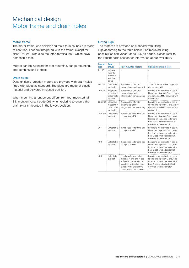
Motor frameThe motor frame, end shields and main terminal box are made of cast iron. Feet are integrated with the frame, except for sizes 160-250 with side mounted terminal box, which have detachable feet.
Motors can be supplied for foot mounting, flange mounting, and combinations of these.
Drain holesDust ignition protection motors are provided with drain holes fitted with plugs as standard. The plugs are made of plastic material and delivered in closed position.
When mounting arrangement differs from foot mounted IM B3, mention variant code 066 when ordering to ensure the drain plug is mounted in the lowest position.
Frame size
Type of lugs Foot mounted motors Flange mounted motors
71, 80 No lugs, weight of motors is less than 25 kg
- -
90-132 Detachable eye bolt
2 pcs on top of motor diagonally placed, size M8
2 pcs on top of motor diagonally placed, size M8
160-200 Integrated in casting / detachable eye bolt
2 pcs on top of motor diagonally placed, integrated in frame casting
Locations for eye bolts: 4 pcs at N-end and 4 pcs at D-end. 2 pcs eye bolts size M12 delivered with each motor
225-250 Integrated in casting / detachable eye bolt
2 pcs on top of motor diagonally placed, integrated in frame casting
Locations for eye bolts: 4 pcs at N-end and 4 pcs at D-end. 2 pcs eye bolts size M16 delivered with each motor
280, 315 Detachable eye bolt
1 pcs close to terminal box on top, size M24
Locations for eye bolts: 4 pcs at N-end and 4 pcs at D-end, one location on top close to terminal box. 2 pcs eye bolts size M24 delivered with each motor
355 Detachable eye bolt
1 pcs close to terminal box on top, size M30
Locations for eye bolts: 4 pcs at N-end and 4 pcs at D-end, one location on top close to terminal box. 2 pcs eye bolts size M30 delivered with each motor
400 Detachable eye bolt
1 pcs close to terminal box on top, size M36
Locations for eye bolts: 4 pcs at N-end and 4 pcs at D-end, one location on top close to terminal box. 2 pcs eye bolts size M36 delivered with each motor
450 Detachable eye bolt
Locations for eye bolts: 4 pcs at N-end and 4 pcs at D-end, one location on top close to terminal box. 3 pcs eye bolts size M42 delivered with each motor
Locations for eye bolts: 4 pcs at N-end and 4 pcs at D-end, one location on top close to terminal box. 2 pcs eye bolts size M42 delivered with each motor
Lifting lugsThe motors are provided as standard with liftinglugs according to the table below. For improved lifting possibilities can variant code 305 be added, please refer to the variant code section for information about availability.
Mechanical designMotor frame and drain holes
ABB Motors and Generators | 9AKK104006 EN 02-2016 213

Heating elements
Heating elements are installed on stator winding coil heads to keep the winding free of corrosion in humid conditions. The power of the heating elements is shown in the table. You can order heating elements with variant code 450 or 451.
Motor size 71 80 90 100 112 132 160 180
Power (W) 25 25 25 25 25 25 25 25
Motor size 200 225 250 280 315 355 400 450
Power (W) 25 60 60 60 2x60 2x60 2x60 2x100
Motors for marine applications mounted on open deck may have heating element powers differing from the ones shown in this table.
214 9AKK104006 EN 02-2016 | ABB Motors and Generators
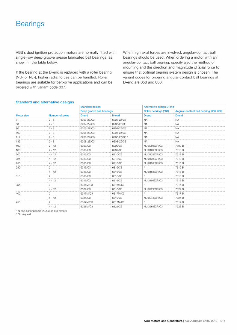
Bearings
ABB’s dust ignition protection motors are normally fitted with single-row deep-groove grease lubricated ball bearings, as shown in the table below.
If the bearing at the D-end is replaced with a roller bearing (NU- or NJ-), higher radial forces can be handled. Roller bearings are suitable for belt-drive applications and can be ordered with variant code 037.
When high axial forces are involved, angular-contact ball bearings should be used. When ordering a motor with an angular-contact ball bearing, specify also the method of mounting and the direction and magnitude of axial force to ensure that optimal bearing system design is chosen. The variant codes for ordering angular-contact ball bearings at D-end are 058 and 060.
Standard and alternative designs
Motor size Number of poles
Standard design Alternative design D-end
Deep groove ball bearings Roller bearings (037) Angular contact ball bearing (058, 060)
D-end N-end D-end D-end
71 2 - 8 6203-2Z/C3 6202-2Z/C3 NA NA
80 2 - 8 6204-2Z/C3 6203-2Z/C3 NA NA
90 2 - 8 6205-2Z/C3 6204-2Z/C3 NA NA
100 2 - 8 6206-2Z/C3 6205-2Z/C3 NA NA
112 2 - 8 6206-2Z/C3 6205-2Z/C3 1) NA NA
132 2 - 8 6208-2Z/C3 6208-2Z/C3 NA NA
160 2 - 12 6309/C3 6209/C3 NU 309 ECP/C3 7309 B
180 2 - 12 6310/C3 6209/C3 NU 310 ECP/C3 7310 B
200 4 - 12 6312/C3 6210/C3 NU 312 ECP/C3 7312 B
225 4 - 12 6313/C3 6212/C3 NU 313 ECP/C3 7313 B
250 4 - 12 6315/C3 6213/C3 NU 315 ECP/C3 7315 B
280 2 6316/C3 6316/C3 2) 7316 B
4 - 12 6316/C3 6316/C3 NU 316 ECP/C3 7316 B
315 2 6316/C3 6316/C3 2) 7316 B
4 - 12 6319/C3 6316/C3 NU 319 ECP/C3 7319 B
355 2 6316M/C3 6316M/C3 2) 7316 B
4 - 12 6322/C3 6316/C3 NU 322 ECP/C3 7322 B
400 2 6317M/C3 6317M/C3 2) 7317 B
4 - 12 6324/C3 6319/C3 NU 324 ECP/C3 7324 B
450 2 6317M/C3 6317M/C3 2) 7317 B
4 - 12 6326M/C3 6322/C3 NU 326 ECP/C3 7326 B1) N-end bearing 6206-2Z/C3 on IE3 motors2) On request
ABB Motors and Generators | 9AKK104006 EN 02-2016 215
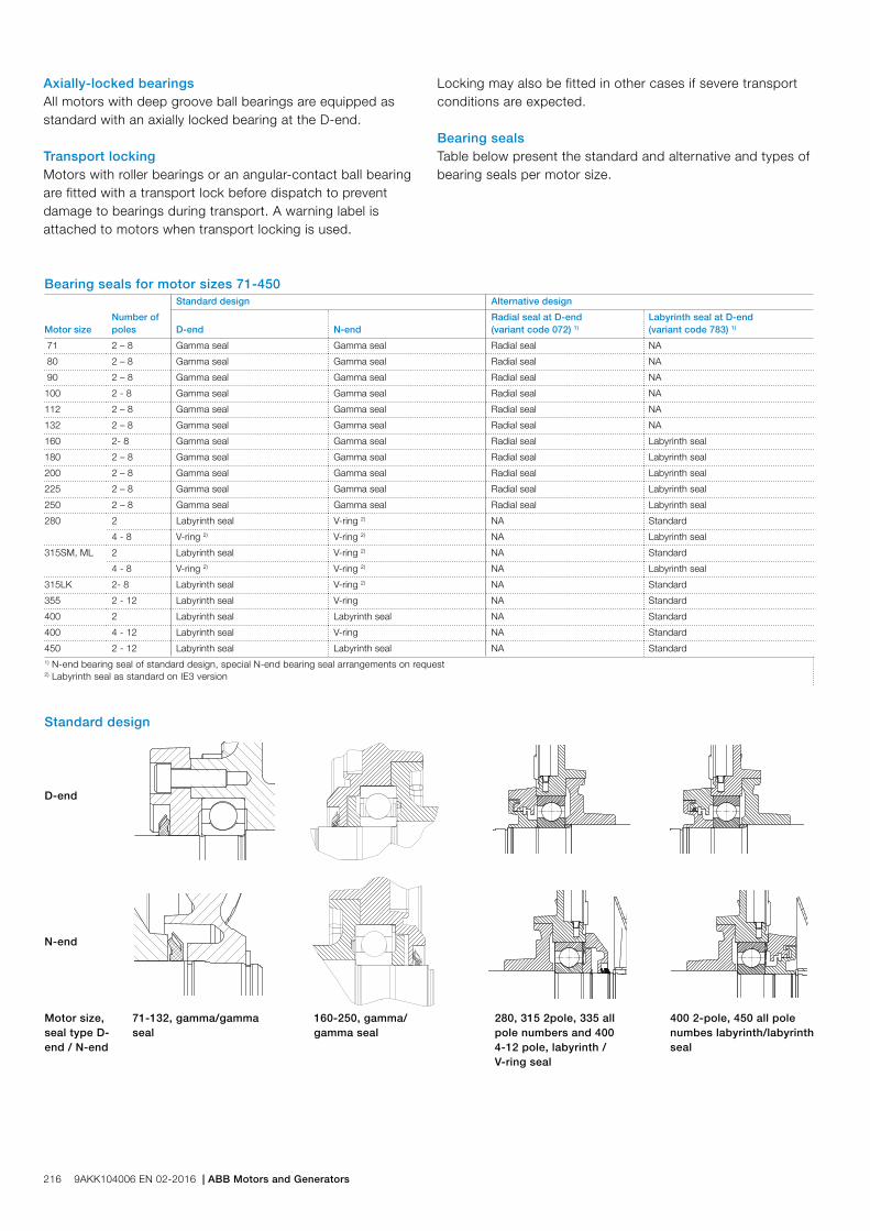
Bearing seals for motor sizes 71-450
Motor sizeNumber ofpoles
Standard design Alternative design
D-end N-endRadial seal at D-end (variant code 072) 1)
Labyrinth seal at D-end (variant code 783) 1)
71 2 – 8 Gamma seal Gamma seal Radial seal NA
80 2 – 8 Gamma seal Gamma seal Radial seal NA
90 2 – 8 Gamma seal Gamma seal Radial seal NA
100 2 - 8 Gamma seal Gamma seal Radial seal NA
112 2 – 8 Gamma seal Gamma seal Radial seal NA
132 2 – 8 Gamma seal Gamma seal Radial seal NA
160 2- 8 Gamma seal Gamma seal Radial seal Labyrinth seal
180 2 – 8 Gamma seal Gamma seal Radial seal Labyrinth seal
200 2 – 8 Gamma seal Gamma seal Radial seal Labyrinth seal
225 2 – 8 Gamma seal Gamma seal Radial seal Labyrinth seal
250 2 – 8 Gamma seal Gamma seal Radial seal Labyrinth seal
280 2 Labyrinth seal V-ring 2) NA Standard
4 - 8 V-ring 2) V-ring 2) NA Labyrinth seal
315SM, ML 2 Labyrinth seal V-ring 2) NA Standard
4 - 8 V-ring 2) V-ring 2) NA Labyrinth seal
315LK 2- 8 Labyrinth seal V-ring 2) NA Standard
355 2 - 12 Labyrinth seal V-ring NA Standard
400 2 Labyrinth seal Labyrinth seal NA Standard
400 4 - 12 Labyrinth seal V-ring NA Standard
450 2 - 12 Labyrinth seal Labyrinth seal NA Standard1) N-end bearing seal of standard design, special N-end bearing seal arrangements on request2) Labyrinth seal as standard on IE3 version
Standard design
D-end
N-end
Motor size,seal type D-end / N-end
71-132, gamma/gamma seal
160-250, gamma/gamma seal
280, 315 2pole, 335 all pole numbers and 400 4-12 pole, labyrinth / V-ring seal
400 2-pole, 450 all pole numbes labyrinth/labyrinth seal
Axially-locked bearingsAll motors with deep groove ball bearings are equipped as standard with an axially locked bearing at the D-end.
Transport lockingMotors with roller bearings or an angular-contact ball bearing are fitted with a transport lock before dispatch to prevent damage to bearings during transport. A warning label is attached to motors when transport locking is used.
Locking may also be fitted in other cases if severe transport conditions are expected.
Bearing sealsTable below present the standard and alternative and types of bearing seals per motor size.
216 9AKK104006 EN 02-2016 | ABB Motors and Generators

Alternative design
D-end
N-end
Motor size, seal type D-end / N-end
80-132, VC072 radial/gamma seals
160-250, VC072 radial/gamma seals
160-250, VC783 labyrinth/gamma seals
Bearing life and lubricationThe nominal life L10h of a bearing is defined according to ISO 281 as the number of operating hours achieved or exceeded by 90 % of identical bearings in a large test series under specified conditions. 50 % of bearings achieve at least five times this lifetime. The calculated bearing life L10h for power transmission by means of coupling is for horizontally mounted motors in sizes up to 315 ≥ 100,000 hours.
LubricationOn delivery, motors in frame size 160 and above are pre-lubricated with high-quality grease. Before first start-up, see instructions for re-lubrication and recommended grease in the installation, operation, maintenance and safety manual for low voltage motors for explosive atmospheres delivered together with the motor, or see the lubrication plate on the motor.
Motors with bearings greased for lifeMotors in frame sizes 71-132 are equipped with bearings greased for life, while this is available as an option for frame sizes 160-250. Bearings are lubricated with high-quality, high-temperature grease. Bearing types are stated on the rating plate.
The approximate lifetime of bearings in four-pole motors is about 40 0000 duty hours. Lifetime is subject to the load conditions of the application run by the motor.
Motors with re-lubrication nipplesIn frame sizes 160-400, the bearing system is provided with valve discs to ease lubrication. Motors are lubricated while running. The grease outlet opening has closing valves at both ends. These should be opened before greasing and closed 1-2 hours after re-greasing. This ensures that the construction is tight and bearings remain dust- and dirt-free.
A grease-collection method can be used optionally.
The following tables show lubrication intervals according to the L1 principle for various nominal speeds in 25 °C ambient temperature. These values apply to horizontally mounted motors (B3) with 80 °C bearing temperature and high-quality grease containing lithium-complex soap and mineral or PAO-oil.
ABB Motors and Generators | 9AKK104006 EN 02-2016 217

Lubrication intervals in duty hours for ball bearings
Framesize
Amountof greaseg/bearing
Amountof greaseg/N-end
OutputkW
Speed3600r/min
Speed3000r/min
OutputkW
Speed1800r/min
Speed1500r/min
OutputkW
Speed1000r/min
OutputkW
Speed500-900r/min
Ball bearings
Lubrication intervals in duty hours
160 13 13 ≤ 18.5 9000 12 000 ≤ 15 18 000 21 500 ≤ 11 24 000 all 24 000
160 13 13 > 18.5 7500 10 000 > 15 15 000 18 000 > 11 22 500 all 24 000
180 15 15 ≤ 22 7000 9000 ≤ 22 15 500 18 500 ≤ 15 24 000 all 24 000
180 15 15 > 22 6000 8500 > 22 14 000 17 000 > 15 21 000 all 24 000
200 20 15 ≤ 37 5500 8000 ≤ 30 14 500 17 500 ≤ 22 23 000 all 24 000
200 20 15 > 37 3000 5500 > 30 10 000 12 000 > 22 16 000 all 20 000
225 23 20 ≤ 45 4000 6500 ≤ 45 13 000 16 500 ≤ 30 22 000 all 24 000
250 23 20 > 45 1500 2500 > 45 5000 6000 > 30 8000 all 10 000
250 30 23 ≤ 55 2500 4000 ≤ 55 9000 11 500 ≤ 37 15 000 all 18 000
250 30 23 > 55 1000 1500 > 55 3500 4500 > 37 6000 all 7000
280 35 35 all 1900 3200 - - - -
280 40 40 - - all 7800 9600 all 13 900 all 15 000
315 35 35 all 1900 3200 - - - -
315 55 40 - - all 5900 7600 all 11 800 all 12 900
355 35 35 all 1900 3200 - - - -
355 70 40 - - all 4000 5600 all 9600 all 10 700
400 40 40 all 1500 2700 - - - -
400 85 55 - - all 3200 4700 all 8600 all 9700
450 40 40 all 1500 2700 - - - -
450 95 70 - - all 2500 3900 all 7700 all 8700
Lubrication intervals in duty hours for roller bearings
Framesize
Amountof greaseg/bearing
Amountof greaseg/N-end
OutputkW
Speed3600r/min
Speed3000r/min
OutputkW
Speed1800r/min
Speed1500r/min
OutputkW
Speed1000r/min
OutputkW
Speed500-900r/min
Roller bearings
Lubrication intervals in duty hours
160 13 13 ≤ 18.5 4500 6000 ≤ 15 9000 10 500 ≤ 11 12 000 all 12 000
160 13 13 > 18.5 3500 5000 > 15 7500 9000 > 11 11 000 all 12 000
180 15 15 ≤ 22 3500 4500 ≤ 22 7500 9000 ≤ 15 12 000 all 12 000
180 15 15 > 22 3000 4000 > 22 7000 8500 > 15 10500 all 12 000
200 20 15 ≤ 37 2750 4000 ≤ 30 7000 8500 ≤ 22 11 500 all 12 000
200 20 15 > 37 1500 2500 > 30 5000 6000 > 22 8000 all 10 000
225 23 20 ≤ 45 2000 3000 ≤ 45 6500 8000 ≤ 30 11 000 all 12 000
225 23 20 > 45 750 1250 > 45 2500 3000 > 30 4000 all 5000
250 30 23 ≤ 55 1000 2000 ≤ 55 4500 5500 ≤ 37 7500 all 9000
250 30 23 > 55 500 750 > 55 1500 2000 > 37 3000 all 3500
280 35 35 all 900 1600 - - - -
280 40 40 - - all 4000 5300 all 7000 all 8500
315 35 35 all 900 1600 - - - -
315 55 40 - - all 2900 3800 all 5900 all 6500
355 35 35 all 900 1600 - - - -
355 70 40 - - all 2000 2800 all 4800 all 5400
400 40 40 all - 1300 - - - -
400 85 55 - - all 1600 2400 all 4300 all 4800
450 40 40 all - 1300 - - - -
450 95 70 - - all 1300 2000 all 3800 all 4400
218 9AKK104006 EN 02-2016 | ABB Motors and Generators
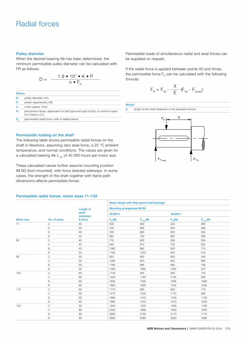
Radial forces
Pulley diameterWhen the desired bearing life has been determined, the minimum permissible pulley diameter can be calculated with FR as follows:
D =1.9 • 107 • K • P
n • FR
Where:
D: pulley diameter, mm
P: power requirement, kW
n: motor speed, r/min.
K: belt tension factor, dependent on belt type and type of duty. A common value for V-belts is 2.5
FR: permissible radial force, refer to tables below.
Permissible loading on the shaftThe following table shows permissible radial forces on the shaft in Newtons, assuming zero axial force, a 25 °C ambient temperature, and normal conditions. The values are given for a calculated bearing life L10h of 40 000 hours per motor size.
These calculated values further assume mounting position IM B3 (foot-mounted), with force directed sideways. In some cases, the strength of the shaft together with flame path dimensions affects permissible forces.
FR = FX0 -
X (FX0 - FXmax)E
Where:
E: length of the shaft extension in the standard version
Permissible loads of simultaneous radial and axial forces can be supplied on request.
If the radial force is applied between points X0 and Xmax, the permissible force FR can be calculated with the following formula:
Permissible radial forces, motor sizes 71–132
Motor size No. of poles
Length ofshaftextensionE (mm)
Basic design with deep groove ball bearings
Mounting arrangement IM B3
20,000 h 40,000 h
FX0(N) FXmax(N) FX0(N) FXmax(N)
71 2 30 540 460 420 360
4 30 700 605 555 480
6 30 780 665 620 530
8 30 860 730 685 580
80 2 40 710 600 385 350
4 40 940 810 725 625
6 40 1060 895 840 710
8 40 1185 1020 940 810
90 2 50 820 690 650 545
4 50 1035 870 820 690
6 50 1185 995 940 790
8 50 1300 1095 1035 870
100 2 60 1130 925 900 735
4 60 1425 1165 1135 925
6 60 1635 1335 1295 1060
8 60 1820 1520 1445 1205
112 2 60 1170 980 925 775
4 60 1475 1235 1170 980
6 60 1690 1310 1340 1120
8 60 1860 1310 1475 1235
132 2 80 1840 1500 1460 1190
4 80 2320 1890 1840 1500
6 80 2660 2165 2110 1715
8 80 2925 2380 2320 1890
ABB Motors and Generators | 9AKK104006 EN 02-2016 219
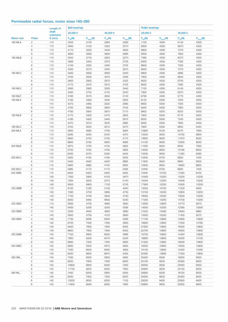
Permissible radial forces, motor sizes 160-280
Motor size Poles
Length ofshaftextensionE (mm)
Ball bearings Roller bearings
20,000 h 40,000 h 20,000 h 40,000 h
FX0(N) FXmax(N) FX0(N) FXmax(N) FX0(N) FXmax(N) FX0(N) FXmax(N)
160 MLA 2 110 3540 2740 2955 2285 7100 4300 6140 4300
4 110 4000 3100 3325 2570 8000 4300 6870 4300
6 110 4170 3200 3440 2655 8600 4300 7270 4300
8 110 4600 3585 3855 2985 9300 4300 7955 4300
160 MLB 2 110 3540 2740 2955 2270 7085 4300 6070 4300
4 110 4085 3300 3370 2725 8300 4300 7055 4300
6 110 4100 3355 3400 2755 8600 4300 7300 4300
8 110 4200 3270 3455 2670 9000 4300 7570 4300
160 MLC 2 110 3400 2600 2855 2200 6800 4300 5885 4300
4 110 3700 3000 3070 2485 7800 4300 6640 4300
6 110 3600 2900 2870 2325 8000 4300 6700 4300
8 110 4170 3370 3370 2725 9000 4300 7585 4300
160 MLD 2 110 3585 2900 3000 2440 7100 4300 6140 4300
4 110 3400 2755 2755 2240 7600 4300 6370 4300
160 MLE 2 110 3185 2570 2640 2140 6785 4300 5770 4300
180 MLA 2 110 4100 3385 3455 2825 8125 5500 7025 5500
4 110 4270 3485 3525 2885 8600 5500 7300 5500
6 110 4700 3800 3855 3155 9400 5500 7900 5500
8 110 4785 3900 3870 3170 9800 5500 8255 5500
180 MLB 2 110 4170 3400 3470 2825 7900 5500 6770 5500
4 110 4185 3400 3440 2810 8500 5500 7200 5500
6 110 4370 3570 3525 2885 9000 5500 7600 5500
180 MLC 4 110 3700 3055 3010 2470 7900 5500 6655 5440
200 MLA 2 110 5600 4685 4700 3925 10900 9100 9470 7900
4 110 6285 5200 5240 4370 12500 9550 10700 8900
6 110 6800 5700 5700 4770 13600 9550 11670 9550
8 110 6800 5700 5600 4685 14100 9550 12000 9550
200 MLB 2 110 5670 4700 4700 3925 11000 9200 9500 7900
4 110 5700 4700 4700 3925 12000 9550 10185 8500
6 110 6400 5370 5300 4425 13200 9550 11200 9385
200 MLC 2 110 5000 4185 4185 3500 10400 8700 8900 7455
4 110 5400 4500 4425 3685 11600 9550 9800 8200
6 110 5800 4885 4740 3955 12500 9550 10600 8800
200 MLD 2 110 4985 4170 4170 3485 10400 8700 8900 7400
225 SMA 2 110 6400 5400 5355 4500 13300 10700 11500 9700
4 140 7300 5900 6155 4970 15400 10250 13200 10250
6 140 7600 6200 6370 5140 16400 10250 14000 10250
8 140 8500 6900 7100 5725 17900 10250 15300 10250
225 SMB 2 110 6100 5185 5155 4340 13000 10700 11200 9455
4 140 7085 5700 5885 4755 15100 10250 12900 10250
6 140 7100 5700 5840 4700 16000 10250 13500 10250
8 140 8000 6485 6600 5340 17300 10250 14700 10250
225 SMC 2 110 5600 4700 4685 3940 12600 10600 10770 9070
4 140 6400 5200 5300 4285 14500 10250 12385 10000
225 SMD 2 110 5500 4640 4600 3880 12420 10460 10640 8960
4 140 5800 4700 4725 3800 13500 10250 11400 9270
250 SMA 2 140 7700 6285 6500 5285 17100 10900 14900 10900
4 140 8700 7000 7300 5900 19800 13800 17000 13785
6 140 9400 7600 7800 6355 21600 13800 18400 13800
8 140 9600 7800 7900 6400 22700 13800 19300 13800
250 SMB 2 140 7100 5800 6000 4885 16700 10900 14400 10900
4 140 7800 6300 6470 5240 18900 13800 16200 13100
6 140 8900 7200 7355 5955 21200 13800 18000 13800
250 SMC 2 140 6800 5500 5670 4600 16300 10900 14000 10900
4 140 7400 6000 6055 4900 18100 13800 15400 12485
6 140 8200 6600 6670 5400 20300 13800 17200 13800
280 SM_ 2 140 7300 6000 5800 4900 20400 6000 16500 6000
4 140 9200 7800 7300 6200 25100 9200 20300 9200
6 140 10600 8900 8400 7000 28300 9200 23000 9200
8 140 11700 9200 9200 7800 30900 9200 25100 9200
280 ML_ 2 140 7400 6200 5800 5000 20600 6200 16700 6200
4 140 9200 7900 7300 6200 25000 9500 20300 9500
6 140 10500 9000 8300 7100 28300 9400 22900 9400
8 140 11600 9500 9200 7900 30800 9500 25000 9500
220 9AKK104006 EN 02-2016 | ABB Motors and Generators
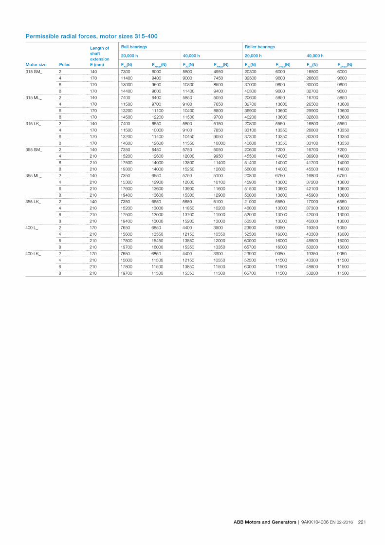
Permissible radial forces, motor sizes 315-400
Motor size Poles
Length ofshaftextensionE (mm)
Ball bearings Roller bearings
20,000 h 40,000 h 20,000 h 40,000 h
FX0(N) FXmax(N) FX0(N) FXmax(N) FX0(N) FXmax(N) FX0(N) FXmax(N)
315 SM_ 2 140 7300 6000 5800 4950 20300 6000 16500 6000
4 170 11400 9400 9000 7450 32500 9600 26600 9600
6 170 13000 9600 10300 8500 37000 9600 30000 9600
8 170 14400 9600 11400 9400 40300 9600 32700 9600
315 ML_ 2 140 7400 6400 5850 5050 20600 5850 16700 5850
4 170 11500 9700 9100 7650 32700 13600 26500 13600
6 170 13200 11100 10400 8800 36900 13600 29900 13600
8 170 14500 12200 11500 9700 40200 13600 32600 13600
315 LK_ 2 140 7400 6550 5800 5150 20800 5550 16800 5550
4 170 11500 10000 9100 7850 33100 13350 26800 13350
6 170 13200 11400 10450 9050 37300 13350 30300 13350
8 170 14600 12600 11550 10000 40800 13350 33100 13350
355 SM_ 2 140 7350 6450 5750 5050 20600 7200 16700 7200
4 210 15200 12600 12000 9950 45500 14000 36900 14000
6 210 17500 14000 13800 11400 51400 14000 41700 14000
8 210 19300 14000 15250 12600 56000 14000 45500 14000
355 ML_ 2 140 7350 6550 5750 5100 20800 6750 16800 6750
4 210 15300 12900 12000 10100 45900 13600 37200 13600
6 210 17600 13600 13900 11600 51500 13600 42100 13600
8 210 19400 13600 15300 12900 56000 13600 45900 13600
355 LK_ 2 140 7350 6650 5650 5100 21000 6550 17000 6550
4 210 15200 13000 11850 10200 46000 13000 37300 13000
6 210 17500 13000 13700 11900 52000 13000 42000 13000
8 210 19400 13000 15200 13000 56500 13000 46000 13000
400 L_ 2 170 7650 6850 4400 3900 23900 9050 19350 9050
4 210 15600 13550 12150 10550 52500 16000 43300 16000
6 210 17800 15450 13850 12000 60000 16000 48800 16000
8 210 19700 16000 15350 13350 65700 16000 53200 16000
400 LK_ 2 170 7650 6850 4400 3900 23900 9050 19350 9050
4 210 15600 11500 12150 10550 52500 11500 43300 11500
6 210 17800 11500 13850 11500 60000 11500 48800 11500
8 210 19700 11500 15350 11500 65700 11500 53200 11500
ABB Motors and Generators | 9AKK104006 EN 02-2016 221

The following tables present permissible axial forces on the shaft in Newtons, assuming zero radial force, a 25 °C ambient temperature, and normal conditions. The values are given for a calculated bearing life of 20,000 and 40,000 hours per motor size.
At 60 Hz, the values must be reduced by 10 percent, and fortwo-speed motors, the higher speed determines permissible axial force. Permissible loads of simultaneous radial and axial forces can be supplied on request.
For axial force FAD, it is assumed that the D-bearing is locked with a locking ring.
Axial forces
Ç
FAD
M00
0023
È
FAZ
FAD Æ
M00
0022
FAZ Å
Mounting arrangement IM B3 Mounting arrangement IM V1
Permissible axial forces, motor sizes 71-132
Motor size Poles
Length ofshaftextensionE (mm)
Mounting arrangement IM B3 Mounting arrangement IM V1
Deep groove ball bearings Deep groove ball bearings
20,000 h 40,000 h 20,000 h 40,000 h
FAD(N) FAZ(N) FAD(N) FAZ(N) FAD(N) FAZ(N) FAD(N) FAZ(N)
71 2 30 615 285 505 175 630 275 520 165
4 30 760 430 615 285 790 410 645 265
6 30 870 540 695 365 890 525 720 355
8 30 960 630 765 435 985 615 785 415
80 2 40 880 300 735 155 915 280 770 135
4 40 1075 495 880 300 1130 455 935 260
6 40 1215 635 985 405 1270 600 1040 370
8 40 1330 750 1070 490 1400 705 1140 450
90 2 50 780 500 620 340 840 455 680 300
4 50 985 705 775 495 1070 650 860 440
6 50 1140 860 890 610 1225 800 975 555
8 50 1265 985 985 705 1355 925 1075 645
100 2 60 925 570 735 350 1285 510 1060 290
4 60 1480 860 1190 570 1600 780 1305 490
6 60 1690 1070 1350 730 1815 995 1470 650
8 60 1865 1245 1480 860 1995 1160 1610 775
112 2 60 1155 595 935 375 1290 505 1070 280
4 60 1445 885 1155 595 1595 785 1300 495
6 60 1655 1095 1315 755 1810 995 1465 650
8 60 1830 1270 1445 885 1985 1170 1600 780
132 2 80 1765 965 1420 620 1925 855 1580 510
4 80 2210 1410 1755 955 2420 1270 1965 815
6 80 2535 1735 2000 1200 2770 1580 2235 1045
8 80 2800 2000 2205 1405 3055 1835 2455 1235
222 9AKK104006 EN 02-2016 | ABB Motors and Generators
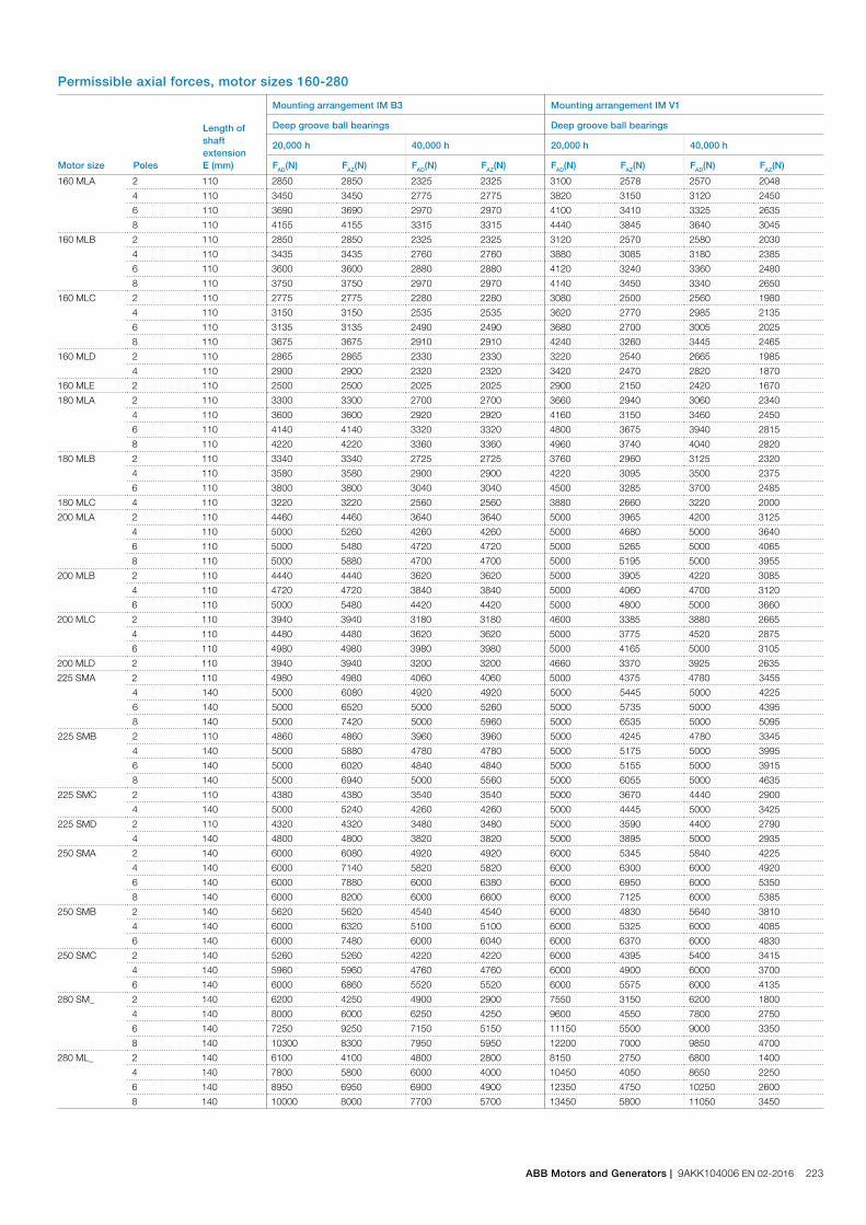
Permissible axial forces, motor sizes 160-280
Motor size Poles
Length ofshaftextensionE (mm)
Mounting arrangement IM B3 Mounting arrangement IM V1
Deep groove ball bearings Deep groove ball bearings
20,000 h 40,000 h 20,000 h 40,000 h
FAD(N) FAZ(N) FAD(N) FAZ(N) FAD(N) FAZ(N) FAD(N) FAZ(N)
160 MLA 2 110 2850 2850 2325 2325 3100 2578 2570 2048
4 110 3450 3450 2775 2775 3820 3150 3120 2450
6 110 3690 3690 2970 2970 4100 3410 3325 2635
8 110 4155 4155 3315 3315 4440 3845 3640 3045
160 MLB 2 110 2850 2850 2325 2325 3120 2570 2580 2030
4 110 3435 3435 2760 2760 3880 3085 3180 2385
6 110 3600 3600 2880 2880 4120 3240 3360 2480
8 110 3750 3750 2970 2970 4140 3450 3340 2650
160 MLC 2 110 2775 2775 2280 2280 3080 2500 2560 1980
4 110 3150 3150 2535 2535 3620 2770 2985 2135
6 110 3135 3135 2490 2490 3680 2700 3005 2025
8 110 3675 3675 2910 2910 4240 3260 3445 2465
160 MLD 2 110 2865 2865 2330 2330 3220 2540 2665 1985
4 110 2900 2900 2320 2320 3420 2470 2820 1870
160 MLE 2 110 2500 2500 2025 2025 2900 2150 2420 1670
180 MLA 2 110 3300 3300 2700 2700 3660 2940 3060 2340
4 110 3600 3600 2920 2920 4160 3150 3460 2450
6 110 4140 4140 3320 3320 4800 3675 3940 2815
8 110 4220 4220 3360 3360 4960 3740 4040 2820
180 MLB 2 110 3340 3340 2725 2725 3760 2960 3125 2320
4 110 3580 3580 2900 2900 4220 3095 3500 2375
6 110 3800 3800 3040 3040 4500 3285 3700 2485
180 MLC 4 110 3220 3220 2560 2560 3880 2660 3220 2000
200 MLA 2 110 4460 4460 3640 3640 5000 3965 4200 3125
4 110 5000 5260 4260 4260 5000 4680 5000 3640
6 110 5000 5480 4720 4720 5000 5265 5000 4065
8 110 5000 5880 4700 4700 5000 5195 5000 3955
200 MLB 2 110 4440 4440 3620 3620 5000 3905 4220 3085
4 110 4720 4720 3840 3840 5000 4060 4700 3120
6 110 5000 5480 4420 4420 5000 4800 5000 3660
200 MLC 2 110 3940 3940 3180 3180 4600 3385 3880 2665
4 110 4480 4480 3620 3620 5000 3775 4520 2875
6 110 4980 4980 3980 3980 5000 4165 5000 3105
200 MLD 2 110 3940 3940 3200 3200 4660 3370 3925 2635
225 SMA 2 110 4980 4980 4060 4060 5000 4375 4780 3455
4 140 5000 6080 4920 4920 5000 5445 5000 4225
6 140 5000 6520 5000 5260 5000 5735 5000 4395
8 140 5000 7420 5000 5960 5000 6535 5000 5095
225 SMB 2 110 4860 4860 3960 3960 5000 4245 4780 3345
4 140 5000 5880 4780 4780 5000 5175 5000 3995
6 140 5000 6020 4840 4840 5000 5155 5000 3915
8 140 5000 6940 5000 5560 5000 6055 5000 4635
225 SMC 2 110 4380 4380 3540 3540 5000 3670 4440 2900
4 140 5000 5240 4260 4260 5000 4445 5000 3425
225 SMD 2 110 4320 4320 3480 3480 5000 3590 4400 2790
4 140 4800 4800 3820 3820 5000 3895 5000 2935
250 SMA 2 140 6000 6080 4920 4920 6000 5345 5840 4225
4 140 6000 7140 5820 5820 6000 6300 6000 4920
6 140 6000 7880 6000 6380 6000 6950 6000 5350
8 140 6000 8200 6000 6600 6000 7125 6000 5385
250 SMB 2 140 5620 5620 4540 4540 6000 4830 5640 3810
4 140 6000 6320 5100 5100 6000 5325 6000 4085
6 140 6000 7480 6000 6040 6000 6370 6000 4830
250 SMC 2 140 5260 5260 4220 4220 6000 4395 5400 3415
4 140 5960 5960 4760 4760 6000 4900 6000 3700
6 140 6000 6860 5520 5520 6000 5575 6000 4135
280 SM_ 2 140 6200 4250 4900 2900 7550 3150 6200 1800
4 140 8000 6000 6250 4250 9600 4550 7800 2750
6 140 7250 9250 7150 5150 11150 5500 9000 3350
8 140 10300 8300 7950 5950 12200 7000 9850 4700
280 ML_ 2 140 6100 4100 4800 2800 8150 2750 6800 1400
4 140 7800 5800 6000 4000 10450 4050 8650 2250
6 140 8950 6950 6900 4900 12350 4750 10250 2600
8 140 10000 8000 7700 5700 13450 5800 11050 3450
ABB Motors and Generators | 9AKK104006 EN 02-2016 223

Permissible axial forces, motor sizes 315-400
Motor size Poles
Length ofshaftextensionE (mm)
Mounting arrangement IM B3 Mounting arrangement IM V1
Deep groove ball bearings Deep groove ball bearings
20,000 h 40,000 h 20,000 h 40,000 h
FAD(N) FAZ(N) FAD(N) FAZ(N) FAD(N) FAZ(N) FAD(N) FAZ(N)
315 SM_ 2 140 6180 4200 4850 2850 7950 2600 6600 1300
4 170 9400 7400 7250 5250 11750 5500 9550 3300
6 170 10900 8900 8350 6350 13600 6300 11050 3750
8 170 12000 10000 9200 7000 15350 7900 12450 5000
315 ML_ 2 140 6050 4050 4750 2750 8650 2300 7300 1)
4 170 9250 7250 7100 5100 12500 5050 10300 2900
6 170 10650 8650 8100 6100 14900 5800 12350 3250
8 170 11500 9900 8900 6800 15400 6300 13600 3400
315 LK_ 2 140 6000 3950 4650 2650 9100 1350 7750 1)
4 170 9100 7150 7000 5000 13100 3850 10900 1700
6 170 10500 8500 7950 5950 15700 4100 13100 1550
8 170 11750 9750 8900 6900 16900 6300 14100 3450
355 SM_ 2 140 3050 6850 1750 5550 6350 4250 4950 2900
4 210 8600 12400 5900 9700 13250 8600 10450 5850
6 210 10550 14350 7300 11100 15650 9580 12350 6270
8 210 12200 16000 8550 12350 17350 12500 13600 8900
355 ML_ 2 140 2900 6700 1600 5400 7100 3700 5750 2350
4 210 8360 12150 5650 9450 14600 7950 11850 5150
6 210 10100 13900 6900 10700 18050 8600 14700 5300
8 210 12000 15800 7300 11000 21100 11650 17000 7600
355 LK_ 2 140 2650 6450 1350 5150 8250 2650 6900 1300
4 210 8200 12000 5450 9250 15650 6600 12850 3800
6 210 9900 13700 6700 10500 19100 7050 15800 3750
8 210 11450 15250 7800 11600 21200 8700 17500 5000
400 L, LK_ 2 170 2150 7150 1) 5800 8650 2150 7220 1)
4 210 7100 13100 4300 10300 16050 6400 13150 3400
6 210 8850 14850 5500 11500 18450 6750 15100 3400
8 210 10450 16450 6750 12750 20100 8350 16450 4700
1) On request.
224 9AKK104006 EN 02-2016 | ABB Motors and Generators
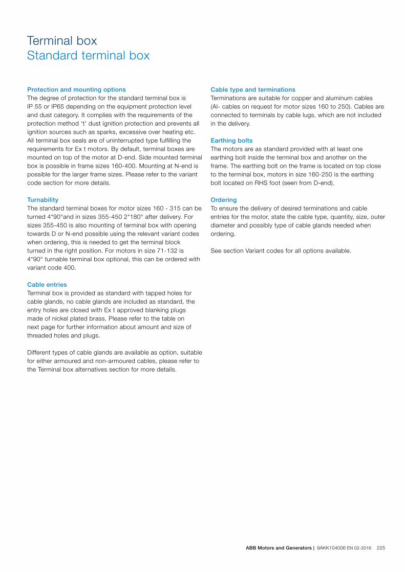
Terminal boxStandard terminal box
Protection and mounting optionsThe degree of protection for the standard terminal box is IP 55 or IP65 depending on the equipment protection level and dust category. It complies with the requirements of the protection method ‘t’ dust ignition protection and prevents all ignition sources such as sparks, excessive over heating etc. All terminal box seals are of uninterrupted type fulfilling the requirements for Ex t motors. By default, terminal boxes are mounted on top of the motor at D-end. Side mounted terminal box is possible in frame sizes 160-400. Mounting at N-end is possible for the larger frame sizes. Please refer to the variant code section for more details.
TurnabilityThe standard terminal boxes for motor sizes 160 - 315 can be turned 4*90°and in sizes 355-450 2*180° after delivery. For sizes 355-450 is also mounting of terminal box with opening towards D or N-end possible using the relevant variant codes when ordering, this is needed to get the terminal block turned in the right position. For motors in size 71-132 is 4*90° turnable terminal box optional, this can be ordered with variant code 400.
Cable entriesTerminal box is provided as standard with tapped holes for cable glands, no cable glands are included as standard, the entry holes are closed with Ex t approved blanking plugs made of nickel plated brass. Please refer to the table on next page for further information about amount and size of threaded holes and plugs.
Different types of cable glands are available as option, suitable for either armoured and non-armoured cables, please refer to the Terminal box alternatives section for more details.
Cable type and terminationsTerminations are suitable for copper and aluminum cables (Al- cables on request for motor sizes 160 to 250). Cables are connected to terminals by cable lugs, which are not included in the delivery.
Earthing boltsThe motors are as standard provided with at least one earthing bolt inside the terminal box and another on the frame. The earthing bolt on the frame is located on top close to the terminal box, motors in size 160-250 is the earthing bolt located on RHS foot (seen from D-end).
OrderingTo ensure the delivery of desired terminations and cable entries for the motor, state the cable type, quantity, size, outer diameter and possibly type of cable glands needed when ordering.
See section Variant codes for all options available.
ABB Motors and Generators | 9AKK104006 EN 02-2016 225

Standard deliveryStandard delivery if no other information is provided.
Motor size Earthing on frameEarthing in main terminal box
71 - 112 M4 M4
132 M5 M5
160 - 250 clamp M6
280 - 400 M10 2xM10
450 M10 4xM12
Motor size
Pole number
Terminal box type
Size of gland plate opening on terminal box
45° angle adaper
Amount and size of threaded plugged holes or cable seal-ing end unit
Max. Connectable core cross section mm2/phase
Number and size of terminal bolts
IE2 and IE3 motors
71 2-8 integr. - - 2xM16x1.5 1x2.5 6 x M4
80 2-8 integr. - - 2xM25x1.5 1x4 6 x M4
90 2-8 integr. - - 2xM25x1.5 1x6 6 x M5
100-132 2-8 integr. - - 2xM32x1.5 1x10 6 x M5
160-180 2-8 63 B - 2xM40x1.5 1x35 6 x M6
200-250 2-8 160 C - 2xM63x1.5 1x70 6 x M10
280 2-8 370/1 D - 2xM63x1.5 2x150 6 x M12
315SM_, ML_ 2-8 370/1 D - 2xM63x1.5 2x240 6 x M12
315LKA, LKB 2-4 370/1 D - 2xM63x1.5 2x240 6 x M12
315LKC 2-4 750/1 E - 2xM75x1.5 4x240 6 x M12
315LK_ 6-8 370/1 D - 2xM63x1.5 2x240 6 x M12
355SMA - SMC 2-4 750/1 E - 2xM75x1.5 4x240 6 x M12
355SMA, SMB 6-8 370/1 D - 2xM63x1.5 2x240 6 x M12
355SMC 6 750/1 E - 2xM75x1.5 4x240 6 x M12
355SMC 8 370/1 D - 2xM63x1.5 2x240 6 x M12
355MLA 2-4 750/1 E - 2xM75x1.5 4x240 6 x M12
355MLB, LK_ 2-4 750/1 E - 2xM75x1.5 4x240 6 x M12
355ML_, LK_ 6-8 750/1 E - 2xM75x1.5 4x240 6 x M12
400 2-8 750/1 E - 2xM75x1.5 4x240 6 x M12
450 LA 2 1200/1 E - 2xM75x1.5 6x240 6 x M12
450 LA 4 1200/1 E - 2xM75x1.5 6x240 6 x M12
450 LB, LC 2-4 1200/1 E - 2xM75x1.5 6x240 6 x M12
450 LA 6 750/1 E - 2xM75x1.5 4x240 6 x M12
450 LB, LC 6 1200/1 E - 2xM75x1.5 6x240 6 x M12
450 8 750/1 E - 2xM75x1.5 4x240 6 x M12
Auxilary cable entries
160-450 2-8 2xM20x1.5 1 x 2.5
226 9AKK104006 EN 02-2016 | ABB Motors and Generators

Terminal boxTerminal box dimensions
Dimensions for terminal box inletsCorresponds to motor sizes 160 and above
Flange opening
cmm
emm
fmm
gmm
damount and sizes of bolts
B 31 120 30 120 4xM6
C 71 194 62 193 4xM6
D 98 284 80 292 6xM10
E 120 365 100 360 6xM12
For motor sizes 71 to 132 the terminal box is integrated in motor frame and the dimensions for terminal boxes can be found in the motor dimension drawings in ABB Library.
To match the correct terminal box with motor sizes 160-450, find the motor type and correspondent terminal box type on the previous page. The box types and heir dimensions are presented on this page.
Terminal box type 63 and 160
Terminal box type 370/1, 750/1 and 1200/1
Terminal box typesacc. to current capacity A1 B1 H1
Gland plateopening
63 248 248 109 B
160 291 302 154 C
370/1 467 348 207 D
750 /1 549 433 231 E
1200/1 740 591 290 E
ABB Motors and Generators | 9AKK104006 EN 02-2016 227
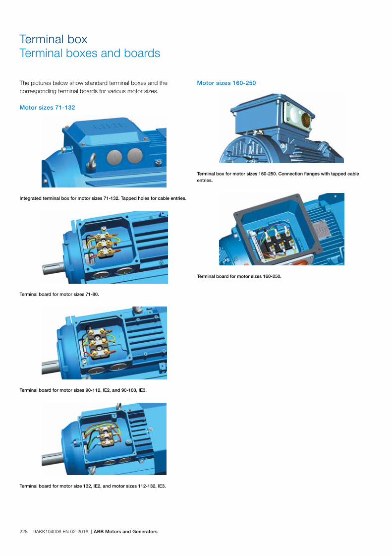
Motor sizes 160-250
Terminal box for motor sizes 160-250. Connection flanges with tapped cable entries.
Terminal board for motor sizes 160-250.
The pictures below show standard terminal boxes and the corresponding terminal boards for various motor sizes. Motor sizes 71-132
Integrated terminal box for motor sizes 71-132. Tapped holes for cable entries.
Terminal board for motor sizes 71-80.
Terminal board for motor sizes 90-112, IE2, and 90-100, IE3.
Terminal board for motor size 132, IE2, and motor sizes 112-132, IE3.
Terminal boxTerminal boxes and boards
228 9AKK104006 EN 02-2016 | ABB Motors and Generators

Terminal box alternatives
Optional cable termination partsThere is a broad selection of cable termination accessories available to allow a safe and reliable termination of one or several supply cables. The most common options are explained in this chapter.
How to order − Check first that the terminal box itself allows mounting
of the desired cable and cores (refer to table showing standard delivery for each motor size). If very large cable are used might it be necessary to use a larger terminal box and larger terminal board than standard
− Select the right cable gland(s) or unit based on the diameter of the cables(s) and suitability for cable type
− Select appropriate adapter or flange to allow mounting on opening in terminal box
Ordering example
Motor and supply cables 110kW, 4-pole, 400V 50Hz, IE2. Cables needed: 1 pcs outer diameter 42mm steel wire armoured cable, single cross section 120 mm2. Cables coming from below.
Motor M3GP 315SMA 4, B3
Adapter (to allow entry of cables coming from below)
Not possible
Cable glands Ex t suitable for armoured cables (an M50 gland will suit this cable)
Variant code 734 (specify cable dimensions)
Gland plate made of steel drilled and tapped with 1 pcs M50 hole (non-std size)
Variant code 554 (1 pcs M50 x 1.5 threaded hole to be specified)
Cable glandsThe motors are delivered as standard with plugged cable entries as described in the previous section. There is a broad selection of different type of cable glands available which are suitable for different types of cable and outer diameter ranges.
Size of threaded opening for cable gland
Cable gland(s) nickel plated brass, Ex t, for non armoured cable, variant code 230 or 731
EMC Cable gland(s) nickel plated brass, Ex t, for non armoured cable, variant code 704
Cable gland Ex d / Ex t for armoured cable with double sealing, variant code 734
Metric (std) Cable outer diameter, mm Cable outer diameter, mm Cable outer diameter, mm Inner sheath diameter, mm
M16 x 1.5 4-8 4-8 7-12 4.5-8
M20 x 1.5 4-12 4-12 10-16 6-10
M25 x 1.5 - - 13.5-19 10-14
M25 x 1.5 *) 10-18 10-18 19-25 14-18
M32 x 1.5 14-24 14-24 25-30 18-23
M40 x 1.5 22-32 22-32 30-36 23-28
M50 x 1.5 - - 36-40 28-32
M50 x 1.5 *) 26-35 26-35 40-46 32-37
M63 x 1.5 - - 46-53 37-43
M63 x 1.5 *) 35-45 35-45 53-60 43-50
M75 x 1.5 46-62 46-62 58-70 48-60
M90 x 1.5 - 78-90 68-80
M100 x 1.5 - 88-100 78-90
*) = High capacity version, delivered as standard with the variant code
Threaded openings for cable glands with NPT thread (variant code 730)The motors are delivered as standard with openings for cable glands with metric threads as listed in the section describing the standard terminal box. If glands with NPT threads will be used must variant code 730 be ordered. If nothing else is stated on the orderer will the sizes in tables below be delivered.
Motor frame size Main cable entries NPT plug
160-180 2 x 1 ¼” 1 x 1 ¼”
200-250 2 x 1 ½” 1 x 1 ½”
280 2 x 2” 1 x 2”
315-450 2 x 3” 1 x 3”
Motor frame size Cable entries for auxiliaries NPT plug
160-450 2 x ¾” 2 x ¾”
ABB Motors and Generators | 9AKK104006 EN 02-2016 229
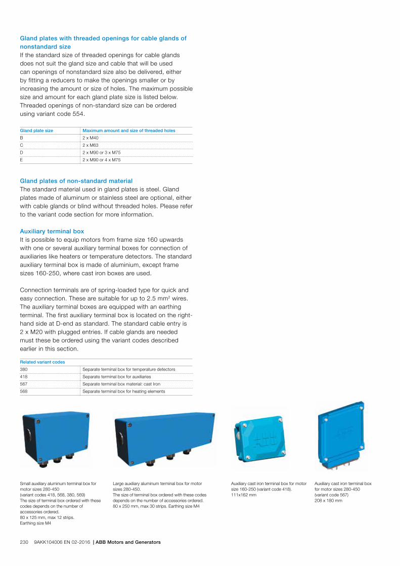
Gland plates with threaded openings for cable glands of nonstandard sizeIf the standard size of threaded openings for cable glands does not suit the gland size and cable that will be used can openings of nonstandard size also be delivered, either by fitting a reducers to make the openings smaller or by increasing the amount or size of holes. The maximum possible size and amount for each gland plate size is listed below. Threaded openings of non-standard size can be ordered using variant code 554.
Gland plate size Maximum amount and size of threaded holes
B 2 x M40
C 2 x M63
D 2 x M90 or 3 x M75
E 2 x M90 or 4 x M75
Gland plates of non-standard materialThe standard material used in gland plates is steel. Gland plates made of aluminum or stainless steel are optional, either with cable glands or blind without threaded holes. Please refer to the variant code section for more information.
Auxiliary terminal boxIt is possible to equip motors from frame size 160 upwards with one or several auxiliary terminal boxes for connection of auxiliaries like heaters or temperature detectors. The standard auxiliary terminal box is made of aluminium, except frame sizes 160-250, where cast iron boxes are used.
Connection terminals are of spring-loaded type for quick and easy connection. These are suitable for up to 2.5 mm2 wires. The auxiliary terminal boxes are equipped with an earthing terminal. The first auxiliary terminal box is located on the right-hand side at D-end as standard. The standard cable entry is 2 x M20 with plugged entries. If cable glands are needed must these be ordered using the variant codes described earlier in this section.
Small auxiliary aluminum terminal box for motor sizes 280-450 (variant codes 418, 568, 380, 569)The size of terminal box ordered with these codes depends on the number of accessories ordered.80 x 125 mm, max 12 strips. Earthing size M4
Large auxiliary aluminum terminal box for motor sizes 280-450.The size of terminal box ordered with these codes depends on the number of accessories ordered.80 x 250 mm, max 30 strips. Earthing size M4
Auxiliary cast iron terminal box for motor size 160-250 (variant code 418). 111x162 mm
Auxiliary cast iron terminal boxfor motor sizes 280-450 (variant code 567) 208 x 180 mm
Related variant codes
380 Separate terminal box for temperature detectors
418 Separate terminal box for auxiliaries
567 Separate terminal box material: cast Iron
568 Separate terminal box for heating elements
230 9AKK104006 EN 02-2016 | ABB Motors and Generators

L
C BB’
E
H
KA
HD
GA
FD
P N
45°
SM
MS
45°
Foot-mounted motor IM 1001, IM B3
Sizes 80 to 200 Protective roof, variant code 005
M00
0267
M00
0268
M00
0270
M00
0269
M00
0271
M00
0272
M00
0230
M00
0231
Flange-mounted motor IM 3001, IM B5
Sizes 225 to 450
IM B14 (IM3601), IM 3602
Motor size
IM 1001, IM B3 AND IM 3001, IM B5 IM 1001, IM B3 IM 3001, IM B5 Protective roof
Dpoles
GApoles
Fpoles
Epoles
L maxpoles A B B' C HD K H M N P S DS LS
2 4-8 2 4-8 2 4-8 2 4-8 2 4-6 2 4-8
71M_ 14 14 16 16 5 5 30 30 264 264 112 90 - 45 178 7 71 130 110 160 10 139 272 272
71ML_ 14 14 16 16 5 5 30 30 294 294 112 90 - 45 178 7 71 130 110 160 10 139 302 302
80M_ 19 19 21.5 21.5 6 6 40 40 331 331 125 100 - 50 194 10 80 165 130 200 12 157 331 331
80ML_ 19 19 21.5 21.5 6 6 40 40 363 363 125 100 112 50 194 10 80 165 130 200 12 157 363 363
90SL_ 24 24 27 27 8 8 50 50 356 356 140 100 125 56 218 10 90 165 130 200 12 177 368 368
90L_ 24 24 27 27 8 8 50 50 390 390 140 100 125 56 218 10 90 165 130 200 12 177 402 402
100L_ 28 28 31 31 8 8 60 60 381 381 160 140 - 63 247 12 100 215 180 250 15 197 395 395
100ML_ 28 28 31 31 8 8 60 60 403 403 160 140 - 63 247 12 100 215 180 250 15 197 417 417
100LK_ 28 28 31 31 8 8 60 60 435 435 160 140 160 63 247 12 100 215 180 250 15 197 449 449
112 (IE2) 28 28 31 31 8 8 60 60 403 403 190 140 - 70 259 12 112 215 180 250 15 197 417 417
112 (IE3) 28 28 31 31 8 8 60 60 442 403 190 140 - 70 258 12 112 215 180 250 15 222 483 483
132 38 38 41 41 10 10 80 80 532 532 216 140 178 89 300 12 132 265 230 300 15 261 552 552
160 42 42 45 45 12 12 110 110 681 681 254 210 254 108 421 14.5 160 300 250 350 19 305 733 733
180 48 48 51.5 51.5 14 14 110 110 726 726 279 241 279 121 461 14.6 180 300 250 350 19 346 779 779
200 55 55 59 59 16 16 110 110 821 821 318 267 305 133 528 18.5 200 350 300 400 19 386 875 875
225 55 60 59 64 16 18 110 140 849 849 356 286 311 149 573 18.5 225 400 350 450 19 425 902 932
250 60 65 64 69 18 18 140 140 884 884 406 311 349 168 626 24 250 500 450 550 19 471 937 937
280 65 75 69 79.5 18 20 140 140 1088 1088 457 368 419 190 759 24 280 500 450 550 18 555 1 180 1190
315SM_ 65 80 69 85 18 22 140 170 1174 1204 508 406 457 216 852 30 315 600 550 660 23 624 1 290 1320
315ML_ 65 90 69 95 18 25 140 170 1285 1315 508 457 508 216 852 30 315 600 550 660 23 624 1 401 1431
315LK_ 65 90 69 95 18 25 140 170 1491 1521 508 508 560 216 852 28 315 600 550 660 23 624 1 607 1637
355SM_ 70 100 74.5 106 20 28 140 210 1409 1479 610 500 560 254 958/944 1) 35 355 740 680 800 23 720 1 476 1546
355ML_ 70 100 74.5 106 20 28 140 210 1514 1584 610 560 630 254 958 35 355 740 680 800 23 720 1 528 1703
355LK_ 70 100 74.5 106 20 28 140 210 1764 1834 610 630 710/900 254 958 35 355 740 680 800 23 720 1 633 1703
400L_ 80 110 85 116 22 28 170 210 1851 1891 710 900 1000 224 1045 35 400 940 880 1000 28 810 1 860 1900
400LK_ 80 100 85 106 22 28 170 210 1851 1891 686 710 800 280 1045 35 400 740 680 800 24 810 1 860 1900
450 - 120 - 127 - 32 - 210 - 2187 800 1000 1120 250 1169/1293 2) 42 450 1080 1000 1150 28 966 - 2342
Motor size LA M N P S T S T
71 8 85 70 105 M6 2.5 M6 2.5
80 8 100 80 120 M6 3 M6 3
90 10 115 95 140 M8 3 M8 3
Dimension drawingsDust ignition protection Ex t case iron motors, 2D and 3D
Tolerances:
A, B ± 0,8
D, DA ISO k6 < Ø 50mm
ISO m6 > Ø 50mm
F, FA ISO h9
H -0.5
N ISO j6
C, CA ± 0.8
In all dimension drawings: The tables give the main dimensions in mm. For detailed drawings please see our web-pages ‘www.abb.com/motors&generators’ or contact ABB.
1) With 750/370 terminal box2) With 1200/750 terminal box
Motor size LA M N P S T S T
100 10 130 110 160 M8 3.5 M8 3.5
112 10 130 110 160 M8 3.5 M8 3.5
132 12 165 130 200 M10 3.5 M10 3.5
ABB Motors and Generators | 9AKK104006 EN 02-2016 231

M00
0731
M00
0730
Certificate examples
M00
0725
-2a
M00
0725
-1a
232 9AKK104006 EN 02-2016 | ABB Motors and Generators

Motors in briefDust ignition protection cast iron motors, size 71 to 180
Motor size 71 80 90 100 112 132 160 180
Stator Material Cast iron, EN-GLJ-150 or better Cast iron, EN-GJL-200 or better
Paint colour shade Blue, Munsell 8B 4.5/3.25
Corrosion class C3 medium according to ISO/EN 12944-5
Feet Cast iron, EN-GLJ-150 or better, integrated with stator Cast iron, EN-GJL-200 or better, integrated with stator
Bearing end shields Material Cast iron, EN-GLJ-150 or better Cast iron, EN-GJL-200 or better
Paint colour shade Blue, Munsell 8B 4.5/3.25
Corrosion class C3 medium according to ISO/EN 12944-5
Bearings D-end 2-8 pole 6203-2Z/C3 6204-2Z/C3 6205-2Z/C3 6206-2Z/C3 6206-2Z/C3 6208-2Z/C3 6309/C3 6310/C3
N-end 2- 8 pole 6202-2Z/C3 6203-2Z/C3 6204-2Z/C3 6205-2Z/C3 6205-2Z/C3 6208-2Z/C3 6209/C3 6209/C3
Axially-locked bearings Inner bearing cover As standard, locked at D-end
Bearing seal Gamma ring
Lubrication Permanent grease lubrication. Regreasable bearings
SPM-nipples Optional As standard
Rating plate Material Stainless steel
Terminal box Frame material Cast iron, EN-GLJ-150 or better Cast iron, EN-GJL-200 or better
Cover material Cast iron, EN-GLJ-150 or better Cast iron, EN-GJL-200 or better
Screws Acid proof steel A4-80
Connections Cable entries 2xM16 plugged 2 x M25 plugged 2 x M32 plugged 2 x M40 + 2 x M20 plugged
Terminals 6 terminals for connection with cable lugs (not included)
Fan Material Polypropylene. Reinforced with glass fibre.
Fan cover Material Steel Hot dip galvanized steel
Paint colour shade Blue, Munsell 8B 4.5/3.25
Corrosion class C3 medium according to ISO/EN 12944-5
Stator winding Material Copper
Insulation Insulation class F
Winding protection 3 pcs thermistors
Rotor winding Material Pressure die-cast aluminum
Balancing Half key balancing
Key ways Closed
Heating elements On request 25 W
Drain holes Closed
External earthing bolt As standard
Enclosure IP 55
Cooling method IC 411
ABB Motors and Generators | 9AKK104006 EN 02-2016 233

Motors in briefDust ignition protection cast iron motors, size 200 to 400
Motor size 200 225 250 280 315 355 400
Stator Material Cast iron, EN-GJL-200 or better
Paint colour shade Blue, Munsell 8B 4.5/3.25
Corrosion class C3 medium according to ISO/EN 12944-5
Feet Cast iron, EN-GJL-200 or better, integrated with stator
Bearing end shields Material Cast iron, EN-GJL-200 or better
Paint colour shade Blue, Munsell 8B 4.5/3.25
Corrosion class C3 medium according to ISO/EN 12944-5
Bearings D-end 2-pole 6312/C3 6313/C3 6315/C3 6316/C3 6316/C3 6316M/C3 6317/C3
4-12 -pole 6312/C3 6313/C3 6315/C3 6316/C3 6319/C3 6322/C3 6324/C3
N-end 2-pole 6210/C3 6212/C3 6213/C3 6316/C3 6319/C3 6316M/C3 6317/C3
4-12 -pole 6210/C3 6212/C3 6213/C3 6316/C3 6316/C3 6316/C3 6319/C3
Axially-locked bearings Inner bearing cover As standard, locked at D-end
Bearing seal Gamma ring V-ring or labyrinth seal
Lubrication Regreasable bearings
SPM-nipples As standard
Rating plate Material Stainless steel
Terminal box Frame material Cast iron, EN-GJL-200 or better
Cover material Cast iron, EN-GJL-200 or better
Cover screws material Steel 8.8, zinc electroplated and chromated
Connections Cable entries 2 x M63 + 2 x M20 plugged 2 x M63 + 2 x M20 plugged Refer to page 226
Terminals 6 terminals for connection with cable lugs (not included)
Fan Material Aluminum
Fan cover Material Hot dip galvanized steel
Paint colour shade Blue, Munsell 8B 4.5/3.25
Corrosion class C3 medium according to ISO/EN 12944-5
Stator winding Material Copper
Insulation Insulation class F
Winding protection 3 pcs thermistors
Rotor winding Material Pressure die-cast aluminum
Balancing Half key balancing
Key ways Closed key way Open key away
Heating elements Optional 25 W 60 W 120 W
Drain holes As standard
External earthing bolt As standard
Enclosure IP 55 or IP 65 depending on EPL and dust group
Cooling method IC 411
234 9AKK104006 EN 02-2016 | ABB Motors and Generators

Motor constructionDust ignition protection cast iron motors, Ex t
Typical exploded view of cast iron motors, frame size 315
1 Stator frame 2 Endshield, D-end 3 Screws for endshield, D-end 4 Endshield, N-end 5 Screws for endshield, N-end 6 Rotor with shaft 7 Key, D-end 8 Terminal box 9 Terminal board 10 Intermediate flange 11 Screws for terminal box cover 12 Outer bearing cover, D-end 13 Valve disc with labyrinth seal, D-end; standard in 2-pole motors (V-ring in 4-8 pole) 14 Bearing, D-end 15 Inner bearing cover, D-end 16 Screws for bearing cover, D-end
M00
0220
17 Outer bearing cover, N-end 18 Seal, N-end 19 Wave spring 20 Valve disc, N-end 21 Bearing, N-end 22 Inner bearing cover, N-end 23 Screws for bearing cover, N-end 24 Fan 25 Fan cover 26 Screws for fan cover 27 Rating plate 28 Regreasing plate 29 Grease nipple, D-end 30 Grease nipple, N-end 31 SPM nipple, D-end 32 SPM nipple, N-end
ABB Motors and Generators | 9AKK104006 EN 02-2016 235

236 9AKK104006 EN 02-2016 | ABB Motors and Generators

Dust ignition protection aluminum motors / Protection by enclosure Ex t IIIB/IIIC T125 °C, Db/DcTotally enclosed squirrel cage three phase low voltage motors, Sizes 71-280, 2.2 to 90 kW
Ordering information 238
Rating plates 239
Technical data 240
IE2 3000 r/min motors 240
IE2 1500 r/min motors 241
IE2 100 r/min motors 242
Variant codes 243
Mechanical design 247
Motor frame and drain holes 247
Bearings 248
Terminal box 253
Dimension drawings 255
Aluminum motors in brief 256
ABB Motors and Generators | 9AKK104006 EN 02-2016 237
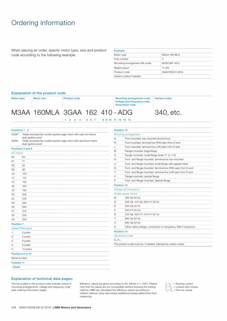
When placing an order, specify motor type, size and product code according to the following example.
Positions 1 - 4
3GGP:
3GAA:
Totally enclosed fan cooled squirrel cage motor with cast iron frame, dust ignition proofTotally enclosed fan cooled squirrel cage motor with aluminum frame, dust ignition proof
Positions 5 and 6
IEC-frame
06 63
07 71
08: 80
09: 90
10: 100
11: 112
13: 132
16: 160
18: 180
20: 200
22: 225
25: 250
28: 280
31: 315
35: 355
40: 400
Position 7
Speed (Pole pairs)
1: 2 poles
2: 4 poles
3: 6 poles
4: 8 poles
5: 10 poles
Positions 8 to 10
Serial number
Position 11
- (Dash)
Ordering information
Position 12
Mounting arrangement
A: Foot-mounted, top-mounted terminal box
R: Foot-mounted, terminal box RHS seen from D-end
L: Foot-mounted, terminal box LHS seen from D-end
B: Flange-mounted, large flange
C: Flange-mounted, small flange (sizes 71 to 112)
H: Foot- and flange-mounted, terminal box top-mounted
J: Foot- and flange-mounted, small flange with tapped holes
S: Foot- and flange-mounted, terminal box RHS seen from D-end
T: Foot- and flange-mounted, terminal box LHS seen from D-end
V Flange-mounted, special flange
F: Foot- and flange-mounted. Special flange
Position 13
Voltage and frequency
Single-speed motors
B: 380 VΔ 50 Hz
D: 400 VΔ, 415 VΔ, 690 VY 50 Hz
E: 500 VΔ 50 Hz
F: 500 VY 50 Hz
S: 230 VΔ, 400 VY, 415 VY 50 Hz
T: 660 VΔ 50 Hz
U: 690 VΔ 50 Hz
X: Other rated voltage, connection or frequency, 690 V maximum
Position 14
Generation code
G, H...
The product code must be, if needed, followed by variant codes.
Explanation of the product codeMotor type Motor size Product code Mounting arrangement code,
Voltage and frequency code,Generation code
Variant codes
M3AA 160MLA 3GAA 162 410 - ADG 340, etc. 1 2 3 4 5 6 7 8 9 10 11 12 13 14
Example
Motor type M3AA 160 MLA
Pole number 4
Mounting arrangement (IM-code) IM B3 (IM 1001)
Rated output 11 kW
Product code 3GAA162410-ADG
Variant codes if needed
238 9AKK104006 EN 02-2016 | ABB Motors and Generators
Is / IN = Starting currentTl / TN = Locked rotor torqueTb / TN = Pull-out torque
The two bullets in the product code indicate choice of mounting arrangements, voltage and frequency code (see ordering information page).
Efficiency values are given according to IEC 60034-2-1; 2007. Please note that the values are not comparable without knowing the testing method. ABB has calculated the efficiency values according to indirect method, stray load losses (additional losses) determined from measuring.
Explanation of technical data pages:

Rating plates
The rating plates are in table form giving values for speed, output, current and power factor at different voltages, there are two rows available for different voltages, usually is the corresponding voltages for star and delta connection stamped. Other voltage and frequency combinations are possible and can be ordered with variant codes 002 or 209. Please refer to the variant code section.
The following information will be shown on the motor rating plate:
− Lowest nominal efficiency at 100%, 75% and 50% rated load
− Efficiency level − Year of manufacture − Type of protection − Apparatus group − Temperature class − Identification number for notified body (category 2
motors only) − Certificate number ATEX and IECEx (if available)
M00
0761
a
M00
0762
a
Aluminum motors size 90-132 Aluminum motors size 160, 180
Aluminum motors size 200-250
Plates
ABB Motors and Generators | 9AKK104006 EN 02-2016 239

IP 65/55 - IC 411 - Insulation class F, temperature rise class BIE2 efficiency class according to IEC 60034-30-1; 2014
Technical data for Ex t IIIB/IIIC T125 °C Db/Dc, IP 65/IP 55 Dust ignition protection aluminum motors
Output kW Motor type Product code
Speed r/min
Efficiency Power factor cos j
Current Torque Moment of inertiaJ = 1/4 GD2 kgm2
Weight kg
Sound pressure level LPA dB
Full load 100%
3/4 load 75%
1/2 load 50%
IN A
Is IN
TN Nm
Tl TN
Tb TN
3000 r/min = 2-poles 400 V 50 Hz CENELEC-design
3 M3AA 100LB 2 3GAA101520-••E 2920 86.40 86.10 84.00 0.9 5.8 9.3 9.8 3.3 3.9 0.005 25 62
4 M3AA 112MB 2 3GAA111320-••E 2885 86.10 87.00 88.00 0.9 7.6 7.6 13.2 2.5 2.8 0.0062 30 68
5.5 M3AA 132SB 2 3GAA131120-••E 2915 88.00 88.10 86.90 0.8 11.0 7.9 18.0 2.6 3.6 0.016 52 73
7.5 M3AA 132SC 2 3GAA131130-••E 2915 88.50 89.10 88.50 0.9 13.6 7.6 24.5 2.2 3.2 0.022 52 73
11 M3AA 160MLA 2 3GAA161410-••G 2938 90.60 91.50 91.10 0.9 19.2 7.5 35.7 2.4 3.1 0.044 91 69
15 M3AA 160MLB 2 3GAA161420-••G 2934 91.50 92.40 92.20 0.9 26.0 7.5 48.8 2.5 3.3 0.053 105 69
18.5 M3AA 160MLC 2 3GAA161430-••G 2932 92.00 93.10 93.10 0.9 31.5 7.5 60.2 2.9 3.4 0.063 123 69
22 M3AA 180MLA 2 3GAA181410-••G 2952 92.20 92.70 92.20 0.9 39.5 7.7 71.1 2.8 3.3 0.076 132 69
30 M3AA 200MLA 2 3GAA201410-••G 2956 93.10 93.50 92.80 0.9 51.6 7.7 96.9 2.7 3.1 0.178 210 72
37 M3AA 200MLB 2 3GAA201420-••G 2959 93.40 93.70 92.90 0.9 63.5 8.2 119 3.0 3.3 0.196 225 72
45 M3AA 225SMA 2 3GAA221210-••G 2961 93.60 93.90 93.10 0.9 78.8 6.7 145 2.5 2.5 0.244 263 74
55 M3AA 250SMA 2 3GAA251210-••G 2967 94.10 94.40 93.80 0.9 95.8 6.8 177 2.2 2.7 0.507 304 75
75 M3AA 280SMA 2 3GAA281210-••G 2968 94.40 94.70 94.30 0.9 128 7.1 241 2.5 2.8 0.583 389 75
90 1) M3AA 280SMB 2 3GAA281220-••G 2971 94.90 95.20 94.70 0.9 153 7.8 289 2.6 3.2 0.644 425 75
3000 r/min = 2-poles 400 V 50 Hz High-output design
30 M3AA 180MLB 2 3GAA181420-••G 2950 92.70 93.50 93.30 0.9 53.0 7.9 97.1 2.8 3.3 0.092 149 69
45 M3AA 200MLC 2 3GAA201430-••G 2957 93.30 93.80 93.20 0.9 79.1 8.1 145 3.1 3.3 0.196 225 72
55 M3AA 225SMB 2 3GAA221220-••G 2961 93.90 94.30 93.60 0.9 96.0 6.5 177 2.4 2.5 0.274 286 74
75 M3AA 250SMB 2 3GAA251220-••G 2970 94.50 94.80 94.40 0.9 128 7.6 241 2.8 3.1 0.583 351 75
Equipment protection level and equipment group subdivison must be selected when ordering by choosing appropriate variant code;
Sizes 90-132334 Ex t, Dust group III B T125C Db, IP6X (non-conductive dust) acc. IEC/EN60079-31 335 Ex t, Dust group III B T125C Dc, IP5X (non-conductive dust) acc. IEC/EN60079-31 336 Ex t, Dust group III C T125 Db, IP6X (conductive dust) acc. IEC/EN60079-31337 Ex t, Dust group III C T125 Dc, IP6X (conductive dust) acc. IEC/EN60079-31
Sizes 160-280340 Ex t, Dust group III B T125C Dc (non-conductive dust) with manufacturers declaration
1) Temperature rise class F
240 9AKK104006 EN 02-2016 | ABB Motors and Generators
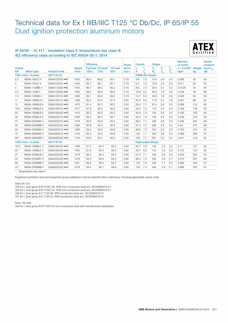
IP 65/55 - IC 411 - Insulation class F, temperature rise class BIE2 efficiency class according to IEC 60034-30-1; 2014
Technical data for Ex t IIIB/IIIC T125 °C Db/Dc, IP 65/IP 55 Dust ignition protection aluminum motors
1) Temperature rise class F
Output kW Motor type Product code
Speed r/min
Efficiency Power factor cos j
Current Torque Moment of inertiaJ = 1/4 GD2 kgm2
Weight kg
Sound pressure level LPA dB
Full load 100%
3/4 load 75%
1/2 load 50%
IN A
Is IN
TN Nm
Tl TN
Tb TN
1500 r/min = 4-poles 400 V 50 Hz CENELEC-design
2.2 M3AA 100LC 4 3GAA102530-••E 1450 86.4 86.2 84.1 0.79 4.6 7.3 14.4 2.8 3.4 0.009 25 54
3 M3AA 100LD 4 3GAA102540-••E 1445 85.7 86.1 85.1 0.79 6.3 7.0 19.8 2.4 3.0 0.011 28 63
4 M3AA 112MB 4 3GAA112320-••E 1445 86.7 86.5 85.2 0.75 8.8 7.3 26.4 3.1 3.4 0.0126 34 64
5.5 M3AA 132M 4 3GAA132300-••E 1465 89.0 89.5 88.6 0.79 10.9 6.3 36.0 1.9 2.6 0.038 48 66
7.5 M3AA 132MA 4 3GAA132310-••E 1460 89.1 89.8 89.4 0.79 14.7 6.4 49.0 1.8 2.6 0.048 59 63
11 M3AA 160MLA 4 3GAA162410-••G 1466 90.4 91.6 91.3 0.84 20.9 6.8 71.6 2.2 2.8 0.081 99 62
15 M3AA 160MLB 4 3GAA162420-••G 1470 91.4 92.3 92.2 0.83 28.5 7.1 97.4 2.6 3.0 0.099 118 62
18.5 M3AA 180MLA 4 3GAA182410-••G 1477 91.9 92.8 92.6 0.84 34.5 7.2 119 2.6 2.9 0.166 146 62
22 M3AA 180MLB 4 3GAA182420-••G 1475 92.3 93.3 93.2 0.84 40.9 7.3 142 2.6 3.0 0.195 163 62
30 M3AA 200MLA 4 3GAA202410-••G 1480 93.2 94.0 93.7 0.84 55.2 7.4 193 2.8 3.0 0.309 218 63
37 M3AA 225SMA 4 3GAA222210-••G 1479 93.4 93.9 93.4 0.84 68.0 7.1 238 2.6 2.9 0.356 240 66
45 M3AA 225SMB 4 3GAA222220-••G 1480 93.9 94.3 93.9 0.85 81.3 7.5 290 2.8 3.2 0.44 273 66
55 M3AA 250SMA 4 3GAA252210-••G 1480 94.4 94.9 94.6 0.85 98.9 7.0 354 2.6 2.9 0.765 314 67
75 M3AA 280SMA 4 3GAA282210-••G 1478 94.3 94.9 94.6 0.85 135 7.1 484 2.8 3.0 0.866 389 67
90 1) M3AA 280SMB 4 3GAA282220-••G 1478 94.6 95.4 95.2 0.84 163 7.7 581 3.2 3.4 0.941 418 67
1500 r/min = 4-poles 400 V 50 Hz High-output design
18.5 M3AA 160MLC 4 3GAA162430-••G 1469 91.4 92.4 92.2 0.84 34.7 7.6 120 3.0 3.2 0.11 127 62
22 1) M3AA 160MLD 4 3GAA162440-••G 1463 91.6 93.0 93.2 0.85 40.7 6.9 143 2.5 2.9 0.125 140 62
37 M3AA 200MLB 4 3GAA202420-••G 1479 93.4 94.4 94.4 0.85 67.2 7.1 238 2.6 2.9 0.343 234 63
55 M3AA 225SMC 4 3GAA222230-••G 1478 94.0 94.6 94.4 0.85 99.3 7.4 355 2.9 3.1 0.474 287 66
68 M3AA 250SMB 4 3GAA252220-••G 1481 94.6 95.0 94.7 0.84 123 7.9 438 3.1 3.5 0.866 350 67
75 1) M3AA 250SMB 4 3GAA252220-••G 1478 94.4 95.1 94.8 0.85 134 7.3 484 2.8 3.1 0.866 350 67
Equipment protection level and equipment group subdivison must be selected when ordering by choosing appropriate variant code;
Sizes 90-132 334 Ex t, Dust group III B T125C Db, IP6X (non-conductive dust) acc. IEC/EN60079-31335 Ex t, Dust group III B T125C Dc, IP5X (non-conductive dust) acc. IEC/EN60079-31 336 Ex t, Dust group III C T125 Db, IP6X (conductive dust) acc. IEC/EN60079-31337 Ex t, Dust group III C T125 Dc, IP6X (conductive dust) acc. IEC/EN60079-31 Sizes 160-280340 Ex t, Dust group III B T125C Dc (non-conductive dust) with manufacturers declaration
ABB Motors and Generators | 9AKK104006 EN 02-2016 241
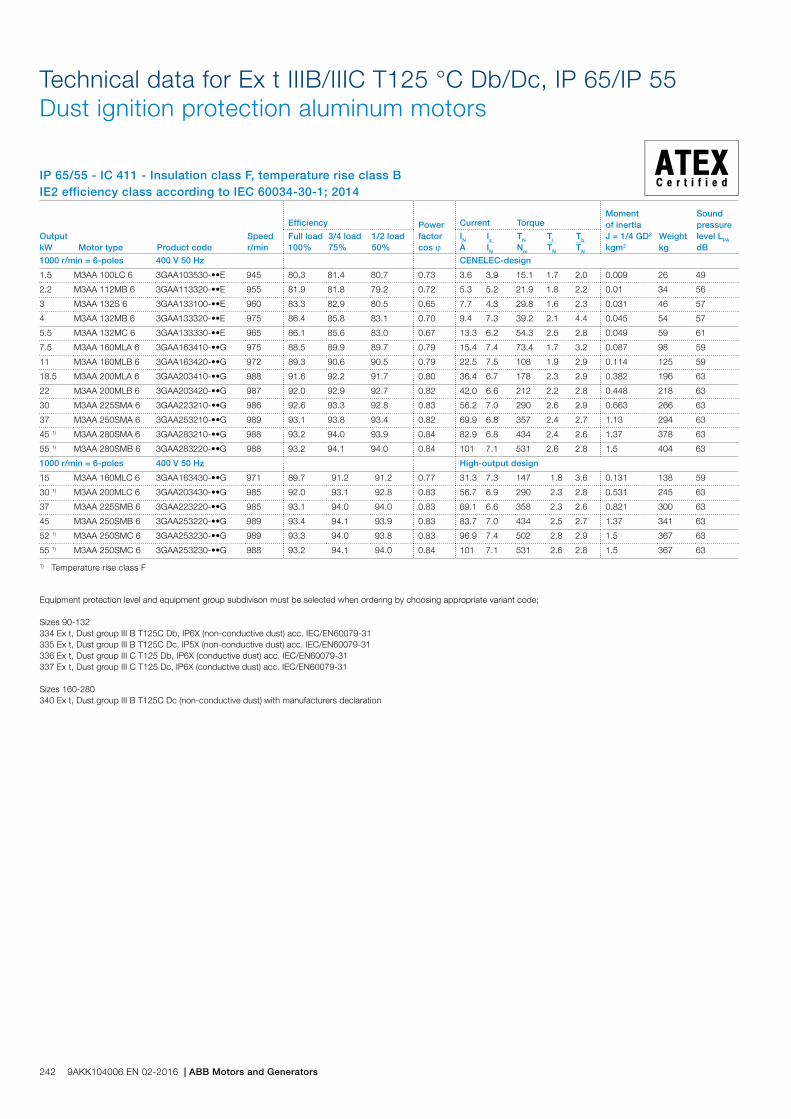
IP 65/55 - IC 411 - Insulation class F, temperature rise class BIE2 efficiency class according to IEC 60034-30-1; 2014
Technical data for Ex t IIIB/IIIC T125 °C Db/Dc, IP 65/IP 55 Dust ignition protection aluminum motors
Output kW Motor type Product code
Speed r/min
Efficiency Power factor cos j
Current Torque Moment of inertiaJ = 1/4 GD2 kgm2
Weight kg
Sound pressure level LPA dB
Full load 100%
3/4 load 75%
1/2 load 50%
IN A
Is IN
TN Nm
Tl TN
Tb TN
1000 r/min = 6-poles 400 V 50 Hz CENELEC-design
1.5 M3AA 100LC 6 3GAA103530-••E 945 80.3 81.4 80.7 0.73 3.6 3.9 15.1 1.7 2.0 0.009 26 49
2.2 M3AA 112MB 6 3GAA113320-••E 955 81.9 81.8 79.2 0.72 5.3 5.2 21.9 1.8 2.2 0.01 34 56
3 M3AA 132S 6 3GAA133100-••E 960 83.3 82.9 80.5 0.65 7.7 4.3 29.8 1.6 2.3 0.031 46 57
4 M3AA 132MB 6 3GAA133320-••E 975 86.4 85.8 83.1 0.70 9.4 7.3 39.2 2.1 4.4 0.045 54 57
5.5 M3AA 132MC 6 3GAA133330-••E 965 86.1 85.6 83.0 0.67 13.3 6.2 54.3 2.5 2.8 0.049 59 61
7.5 M3AA 160MLA 6 3GAA163410-••G 975 88.5 89.9 89.7 0.79 15.4 7.4 73.4 1.7 3.2 0.087 98 59
11 M3AA 160MLB 6 3GAA163420-••G 972 89.3 90.6 90.5 0.79 22.5 7.5 108 1.9 2.9 0.114 125 59
18.5 M3AA 200MLA 6 3GAA203410-••G 988 91.6 92.2 91.7 0.80 36.4 6.7 178 2.3 2.9 0.382 196 63
22 M3AA 200MLB 6 3GAA203420-••G 987 92.0 92.9 92.7 0.82 42.0 6.6 212 2.2 2.8 0.448 218 63
30 M3AA 225SMA 6 3GAA223210-••G 986 92.6 93.3 92.8 0.83 56.2 7.0 290 2.6 2.9 0.663 266 63
37 M3AA 250SMA 6 3GAA253210-••G 989 93.1 93.8 93.4 0.82 69.9 6.8 357 2.4 2.7 1.13 294 63
45 1) M3AA 280SMA 6 3GAA283210-••G 988 93.2 94.0 93.9 0.84 82.9 6.8 434 2.4 2.6 1.37 378 63
55 1) M3AA 280SMB 6 3GAA283220-••G 988 93.2 94.1 94.0 0.84 101 7.1 531 2.6 2.8 1.5 404 63
1000 r/min = 6-poles 400 V 50 Hz High-output design
15 M3AA 160MLC 6 3GAA163430-••G 971 89.7 91.2 91.2 0.77 31.3 7.3 147 1.8 3.6 0.131 138 59
30 1) M3AA 200MLC 6 3GAA203430-••G 985 92.0 93.1 92.8 0.83 56.7 6.9 290 2.3 2.8 0.531 245 63
37 M3AA 225SMB 6 3GAA223220-••G 985 93.1 94.0 94.0 0.83 69.1 6.6 358 2.3 2.6 0.821 300 63
45 M3AA 250SMB 6 3GAA253220-••G 989 93.4 94.1 93.9 0.83 83.7 7.0 434 2.5 2.7 1.37 341 63
52 1) M3AA 250SMC 6 3GAA253230-••G 989 93.3 94.0 93.8 0.83 96.9 7.4 502 2.8 2.9 1.5 367 63
55 1) M3AA 250SMC 6 3GAA253230-••G 988 93.2 94.1 94.0 0.84 101 7.1 531 2.6 2.8 1.5 367 63
1) Temperature rise class F
Equipment protection level and equipment group subdivison must be selected when ordering by choosing appropriate variant code;
Sizes 90-132334 Ex t, Dust group III B T125C Db, IP6X (non-conductive dust) acc. IEC/EN60079-31335 Ex t, Dust group III B T125C Dc, IP5X (non-conductive dust) acc. IEC/EN60079-31336 Ex t, Dust group III C T125 Db, IP6X (conductive dust) acc. IEC/EN60079-31337 Ex t, Dust group III C T125 Dc, IP6X (conductive dust) acc. IEC/EN60079-31
Sizes 160-280340 Ex t, Dust group III B T125C Dc (non-conductive dust) with manufacturers declaration
242 9AKK104006 EN 02-2016 | ABB Motors and Generators
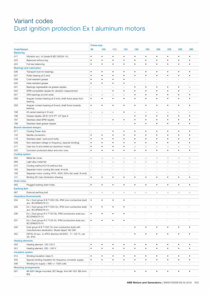
Variant codesDust ignition protection Ex t aluminum motors
Code/Variant
Frame size
90 100 112 132 160 180 200 225 250 280Balancing
417 Vibration acc. to Grade B (IEC 60034-14). • • • • • • • • • •
423 Balanced without key. • • • • • • • • • •
424 Full-key balancing • • • • • • • • • •
Bearings and Lubrication
036 Transport lock for bearings. • • • • • • • • • •
037 Roller bearing at D-end. • • • • • • • • • •
039 Cold-resistant grease • • • • - - - - - -
040 Heat-resistant grease • • • • - - - - - -
041 Bearings regreasable via grease nipples. - - - - • • • • • ○
043 SPM compatible nipples for vibration measurement - - • • • • • • • ○
057 2RS bearings at both ends. ○ ○ ○ ○ • • • • • •
058 Angular contact bearing at D-end, shaft force away from bearing.
• • • • • • • • • •
059 Angular contact bearing at N-end, shaft force towards bearing.
• • • • • • • • • •
188 63-series bearing in D-end ○ ○ ○ • ○ ○ ○ ○ ○ ○
796 Grease nipples JIS B 1575 PT 1/8 Type A - - - - • • • • • •
797 Stainless steel SPM nipples - - • • • • • • • •
798 Stainless steel grease nipples - - - - • • • • • •
Branch standard designs
071 Cooling Tower duty - - • • • • • • • •
142 Manilla connection. • • • • • • • • • •
178 Stainless steel / acid proof bolts. • • • • • • • • • •
209 Non-standard voltage or frequency, (special winding). • • • • • • • • • •
217 Cast iron D-end shield (on aluminum motor). • • • • ○ ○ ○ ○ ○ ○
425 Corrosion protected stator and rotor core. • • • • • • • • • •
Cooling system
053 Metal fan cover. ○ ○ ○ ○ ○ ○ ○ ○ ○ ○
068 Light alloy metal fan ○ ○ ○ ○ ○ ○ ○ ○ ○ ○
075 Cooling method IC418 (without fan). - - - - - - - - - -
183 Separate motor cooling (fan axial, N-end). - - - - - - - - - -
189 Separate motor cooling, IP44, 400V, 50Hz (fan axial, N-end). - - - - - - - - - -
141 Binding 2D main dimension drawing. • • • • • • • • • •
Drain holes
065 Plugged existing drain holes. • • • • • • • • • •
Earthing Bolt
067 External earthing bolt. ○ ○ ○ ○ ○ ○ ○ ○ ○ ○
Hazardous Environments
334 Ex t, Dust group III B T125C Db, IP6X (non-conductive dust) acc. IEC/EN60079-31.
• • • • - - - - - -
335 Ex t, Dust group III B T125C Dc, IP5X (non-conductive dust) acc. IEC/EN60079-31.
• • • • - - - - - -
336 Ex t, Dust group III C T125 Db, IP6X (conductive dust) acc. IEC/EN60079-31.
• • • • - - - - - -
337 Ex t, Dust group III C T125 Dc, IP6X (conductive dust) acc. IEC/EN60079-31.
• • • • - - - - - -
340 Dust group III B T125C Dc (non-conductive dust) with manufacturers declaration. Musta täppä 160-280
- - - - • • • • • •
452 DIP/Ex tD acc. to ATEX directive 94/9/EC , T= 125 ºC, cat. 3D, IP55
- - - - • • • • • •
Heating elements
450 Heating element, 100-120 V • • • • • • • • • •
451 Heating element, 200 - 240 V • • • • • • • • • •
Insulation system
014 Winding insulation class H. • • • • • • • • • •
405 Special winding insulation for frequency converter supply. • • • • • • • • • •
406 Winding for supply > 690 <= 1000 volts - - - - - - - - - -
Mounting arrangements
007 IM 3001 flange mounted, IEC flange, from IM 1001 (B5 from B3).
- - - - • • • • • •
ABB Motors and Generators | 9AKK104006 EN 02-2016 243

Code/Variant
Frame size
90 100 112 132 160 180 200 225 250 280008 IM 2101 foot/flange mounted, IEC flange, from IM 1001 (B34
from B3).• • • • • - - - - -
009 IM 2001 foot/flange mounted, IEC flange, from IM 1001 (B35 from B3).
• • • • • • • • • •
047 IM 3601 flange mounted, IEC flange, from IM 3001 (B14 from B5).
• • • • • - - - - -
048 IM 3001 flange mounted, IEC flange, from IM 3601 (B5 from B14).
• • • • - - - - - -
066 Modified for specified mounting position differing from IM B3 (1001), IM B5 (3001), B14 (3601), IM B35 (2001), IM B34 (2101)
• • • • • • • • • •
080 (IM 3001) Flange mounted, DIN A-flange. • • - - - - - - - -
090 (IM 2101) foot/flange mounted, DIN C-flange, from IM 1001 (B34 from B3).
• • - - - - - - - -
091 (IM 2001) foot/flange mounted, DIN A-flange, from IM 1001 (B35 from B3).
• • - - - - - - - -
093 IM 3601 flange mounted, IEC flange, from IM 1001 (B14 from B3).
• • • - - - - - - -
200 Flange ring holder. • • • • - - - - - -
218 Flange ring FT 85. • - - - - - - - - -
219 Flange ring FT 100. • - - - - - - - - -
220 Flange ring FF 100. • - - - - - - - - -
223 Flange ring FF 115. • - - - - - - - - -
224 Flange ring FT 115. • - - - - - - - - -
226 Flange ring FF 130. • • • - - - - - - -
227 Flange ring FT 130. • • • - - - - - - -
229 Flange FT 130. - • • - - - - - - -
233 Flange ring FF 165. • • • - - - - - - -
234 Flange ring FT 165. • • • - - - - - - -
235 Flange FF 165. • - - - - - - - - -
236 Flange FT 165. - - - • - - - - - -
243 Flange ring FF 215. - - • • - - - - - -
244 Flange ring FT 215. - • • • - - - - - -
245 Flange FF 215. - • • - - - - - - -
253 Flange ring FF 265. - - - • - - - - - -
254 Flange ring FT 265. - - - • - - - - - -
255 Flange FF 265. - - - • - - - - - -
260 Flange FT 115. • - - - - - - - - -
306 IM 1001 foot mounted, from IM 3601 (B3 from B14). • • • • - - - - - -
307 IM 2101 foot/flange mounted, IEC flange, from IM 3601 (B34 from B14).
• • • • - - - - - -
308 IM 2001 foot/flange mounted, IEC flange, from IM 3601 (B35 from B14).
• • • • - - - - - -
309 IM 1001 foot mounted, from IM 3001 (B3 from B5). • • • • - - - - - -
310 IM 2101 foot/flange mounted, IEC flange, from IM 3001 (B34 from B5).
• • • • - - - - - -
311 IM 2001 foot/flange mounted, IEC flange, from IM 3001 (B35 from B5).
• • • • - - - - - -
312 IM 1001 foot mounted, from IM 2101 (B3 from B34). • • • • - - - - - -
313 IM 3601 flange mounted, IEC flange, from IM 2101 (B14 from B34).
• • • - - - - - - -
314 IM 3001 flange mounted, IEC flange, from IM 2101 (B5 from B34).
• • • - - - - - - -
315 IM 2001 foot/flange mounted, IEC flange, from IM 2101 (B35 from B34).
• • • • - - - - - -
316 IM 1001 foot mounted, from IM 2001 (B3 from B35). • • • • - - - - - -
317 IM 3601 flange mounted, IEC flange, from IM 2001 (B14 from B35).
• • • - - - - - - -
319 IM 2101 foot/flange mounted, IEC flange, from IM 2001 (B34 from B35).
• • • • - - - - - -
Painting
114 Special paint color, standard grade • • • • • • • • • •
Protection
005 Protective roof, vertical motor, shaft down. • • • • • • • • • •
072 Radial seal at D-end. Not possible for 2-pole , 280 and 315 frames
• • • • • • • • • •
158 Degree of protection IP65. • • • • • • • • • •
211 Weather protected, IP xx W • • • • • • • • • •
403 Degree of protection IP56. • • • • • • • • • •
244 9AKK104006 EN 02-2016 | ABB Motors and Generators

Code/Variant
Frame size
90 100 112 132 160 180 200 225 250 280404 Degree of protection IP56, without fan and fan cover. - - - - - - - - - -
784 Gamma-seal at D-end. ○ ○ ○ ○ • • • • • •
Rating & instruction plates
002 Restamping voltage, frequency and output, continuous duty. • • • • • • • • • •
004 Additional text on std rating plate (max 12 digits on free text line).
• • • • • • • • • •
095 Restamping output (maintained voltage, frequency), intermittent duty.
• • • • • • • • • •
098 Stainless rating plate. • • • • • • • • • •
135 Mounting of additional identification plate, stainless. • • • • • • • • • -
138 Mounting of additional identification plate, aluminium. • • • • • • • • • •
139 Additional identification plate delivered loose. • • • • • • • • • •
159 Additional plate with text „Made in ....“ • • • • • • • • • •
160 Additional rating plate affixed. • • • • • • • • • •
161 Additional rating plate delivered loose. • • • • • • • • • •
163 Frequency converter rating plate. Rating data according to quotation.
• • • • • • • • • •
198 Aluminum rating plate. ○ ○ ○ • ○ ○ ○ ○ ○ ○
332 Baldor Catalogue # • • • • • • • • • •
333 Not for use in the USA • • • • • • • • • •
Shaft & rotor
069 Two shaft extensions according to catalog drawings. • • • • • • • • • •
070 Special shaft extension at D-End, standard shaft material • • • • - - - - - -
131 Motor delivered with half key (key not exceeding shaft diameter)
• • • • • • • • • •
156 Cylindrical shaft extension, N-end, without key-way. • • • • - - - - - -
165 Shaft extension with open keyway • • • • • • • • • •
410 Shaft material stainless steel • • - - - - - - - -
591 Special shaft extension according to customer specification. • • • • • • • • • •
600 Special shaft extension at N-end, standard shaft material. • • • • - - - - - -
Standards and Regulations
010 Fulfilling CSA Safety Certificate. • • • • • • • • • •
242 Fulfilling CSA Energy Efficiency Verification IE2 (code 010 included)
- - - - • • • • • •
408 Fulfilling EISA Subtype II efficiency requirements, CC031A. - - - - • • • • • •
543 Australian MEPS • • • • • • • • • -
Stator winding temperature sensors
435 PTC - thermistors (3 in series), 130 ºC, in stator winding • • • • • • • • • •
436 PTC - thermistors (3 in series), 150 ºC, in stator winding • • • • ○ ○ ○ ○ ○ ○
437 PTC - thermistors (3 in series), 170 ºC, in stator winding • • • • • • • • • •
439 PTC - thermistors (2x3 in series), 150 ºC, in stator winding • • • • • • • • • •
440 PTC - thermistors (3 in series, 110ºC & 3 in series, 130ºC), in stator winding.
• • • • - - - - - -
441 PTC - thermistors (3 in series, 130 ºC & 3 in series, 150 ºC), in stator winding
• • • • • • • • • •
442 PTC - thermistors (3 in series, 150 ºC & 3 in series, 170 ºC), in stator winding
• • • • • • • • • •
Terminal box
015 Motor supplied in D connection. • • • • • • • • • •
017 Motor supplied in Y connection. • • - - • • • • • •
021 Terminal box LHS (seen from D-end). - - - - - - • • • •
136 Extended cable connection, standard terminal box. • • • • - - - - - -
137 Extended cable connection, low terminal box, „Flying leads“. • • • • - - - - - -
180 Terminal box RHS (seen from D-end). - - - - - - • • • •
230 Standard metal cable gland. • • • • • • • • • •
467 Lower than standard terminal box and rubber extended cable. Cable length 2 m
- - • • • • • • • •
729 Aluminum non-drilled flange for cable glands - - - - - - • • • •
731 Two standard metal cable glands. - • • • • • • • • •
739 Prepared for metric cable glands according to DIN 42925, draft aug. 1999.
- - • • - - - - - -
Testing
140 Test confirmation. - - - - • • • • • •
145 Type test report from a catalogue motor, 400V 50Hz. • • • • • • • • • •
146 Type test with report for one motor from specific delivery batch.
• • • • • • • • • •
147 Type test with report for motor from specific delivery batch, customer witnessed.
• • • • • • • • • •
ABB Motors and Generators | 9AKK104006 EN 02-2016 245
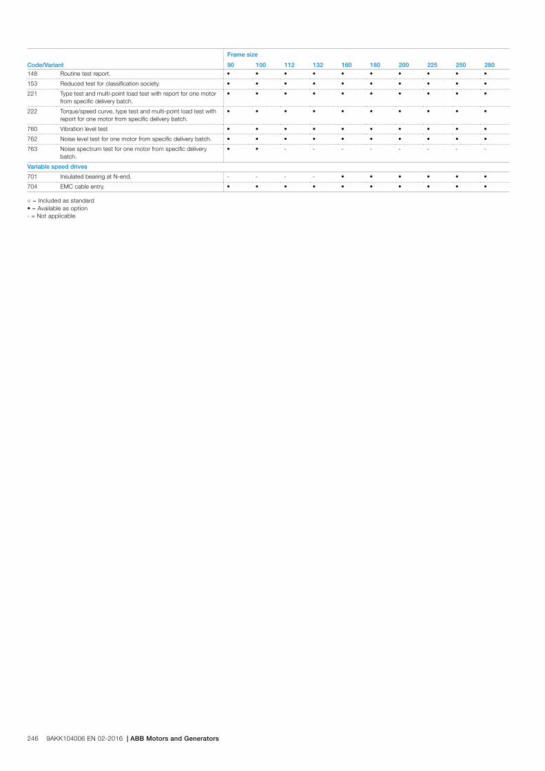
Code/Variant
Frame size
90 100 112 132 160 180 200 225 250 280148 Routine test report. • • • • • • • • • •
153 Reduced test for classification society. • • • • • • • • • •
221 Type test and multi-point load test with report for one motor from specific delivery batch.
• • • • • • • • • •
222 Torque/speed curve, type test and multi-point load test with report for one motor from specific delivery batch.
• • • • • • • • • •
760 Vibration level test • • • • • • • • • •
762 Noise level test for one motor from specific delivery batch. • • • • • • • • • •
763 Noise spectrum test for one motor from specific delivery batch.
• • - - - - - - - -
Variable speed drives
701 Insulated bearing at N-end. - - - - • • • • • •
704 EMC cable entry. • • • • • • • • • •
○ = Included as standard• = Available as option- = Not applicable
246 9AKK104006 EN 02-2016 | ABB Motors and Generators
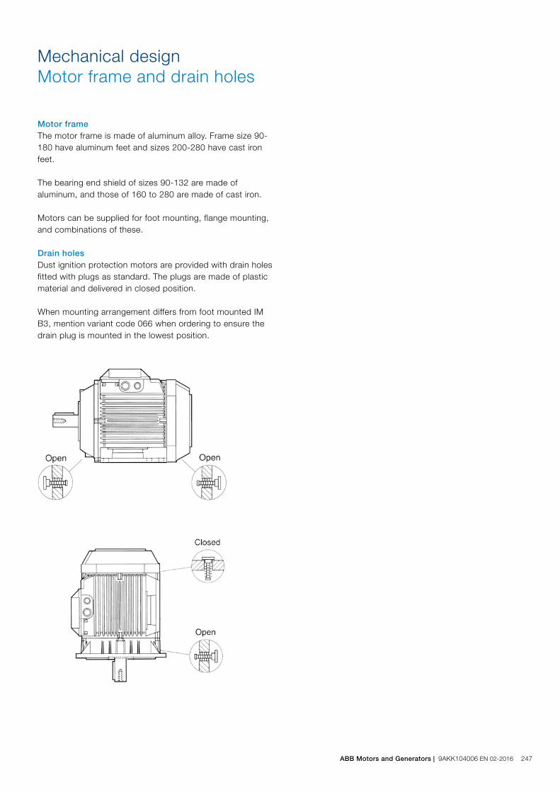
Motor frameThe motor frame is made of aluminum alloy. Frame size 90-180 have aluminum feet and sizes 200-280 have cast iron feet.
The bearing end shield of sizes 90-132 are made of aluminum, and those of 160 to 280 are made of cast iron.
Motors can be supplied for foot mounting, flange mounting, and combinations of these.
Drain holesDust ignition protection motors are provided with drain holes fitted with plugs as standard. The plugs are made of plastic material and delivered in closed position.
When mounting arrangement differs from foot mounted IM B3, mention variant code 066 when ordering to ensure the drain plug is mounted in the lowest position.
Mechanical designMotor frame and drain holes
ABB Motors and Generators | 9AKK104006 EN 02-2016 247

Bearings
ABB’s alumimum dust ignition protrection motors are as standard fitted with single-row ball bearings according to the table below.
Standard design: Deep groove ball bearings
Motor size
Foot and flange mounted motor
D-end N-end
90 6205-2RSH/C3 6204-2RSH/C3
100 6306-2RS1/C3 6205-2RSH/C3
112 6306-2RS1/C3 6205-2RSH/C3
132 6208-2RS1/C3 6206-2RS1/C3
160 6309-2Z/C3 6209-2Z/C3
180 6310-2Z/C3 6209-2Z/C3
200 6312-2Z/C3 6210-2Z/C3
225 6313-2Z/C3 6212-2Z/C3
250 6315-2Z/C3 6213-2Z/C3
280 2-pole 6315/C3 6213/C3
280 4-8 pole 6316/C3 6213/C3
Axially-locked bearingsAll motors with deep groove ball bearings are equipped as standard with an axially locked bearing at the D-end. For sizes 90-132 is the locking done by a spring washer at N-end pushing the rotor towards D-end.
Bearing sealsMotors in sizes 90-132 are provided with gamma seals at both D and N-end, motors in sizes 160-280 have V-rings at both ends. The sizes 90-132 have in addition to the shaft seals 2RS type bearings with rubber seals for improved protection.
Bearing life and lubricationThe nominal life L10h of a bearing is defined according to ISO 281 as the number of operating hours achieved or exceeded by 90 % of identical bearings in a large test series under specified conditions. 50 % of bearings achieve at least five times this lifetime. The life time is dependent on various factors such as bearing load, motor speed, operating temperature and the purity of the grease. The permissible radial and axial loading for different motor sizes is shown in the tables on following pages.
The tables are valid for 50Hz.
LubricationMotors in size 90-250 are delivered with greased for life shielded bearings as standard, as an option are also regreasable bearings with grease nipples available for sizes 160-250. Motors of size 280 are provided with regreasable bearings as standard.
248 9AKK104006 EN 02-2016 | ABB Motors and Generators

Radial forces
Pulley diameterWhen the desired bearing life has been determined, the minimum permissible pulley diameter can be calculated with FR as follows:
D =1.9 • 107 • K • P
n • FR
Where:
D: pulley diameter, mm
P: power requirement, kW
n: motor speed, r/min.
K: belt tension factor, dependent on belt type and type of duty. A common value for V-belts is 2.5
FR: permissible radial force, refer to tables below.
Permissible loading on the shaftThe following table shows permissible radial forces on the shaft in Newtons, assuming zero axial force, a 25 °C ambient temperature, and normal conditions. The values are given for a calculated bearing life L10h of 40 000 hours per motor size.
These calculated values further assume mounting position IM B3 (foot-mounted), with force directed sideways. In some cases, the strength of the shaft together with flame path dimensions affects permissible forces
FR = FX0 -
X (FX0 - FXmax)E
Where:
E: length of the shaft extension in the standard version
Permissible loads of simultaneous radial and axial forces can be supplied on request.
If the radial force is applied between points X0 and Xmax, the permissible force FR can be calculated with the following formula:
Permissible radial forces, motor sizes 90-132
Motor size Poles
Lengthof shaftextensionE (mm)
Ball bearingsBasic design with deep groove ball bearings
25000 hours 40000 hours
FX0 (N) FXmax (N) FX0 (N) FXmax (N)
90 2-8 50 1010 810 1010 810
100 2-8 60 2280 1800 2280 1800
112 2-8 60 2280 1800 2280 1800
132 2-8 80 2120 1610 2120 1610
ABB Motors and Generators | 9AKK104006 EN 02-2016 249
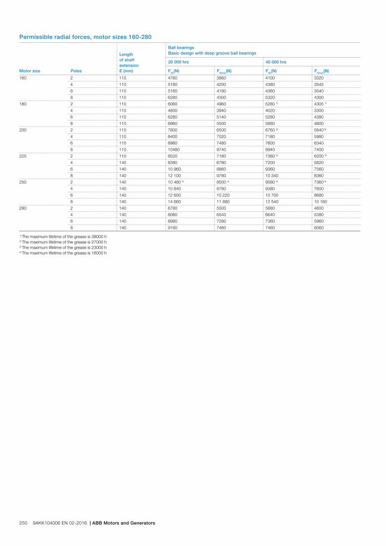
Permissible radial forces, motor sizes 160-280
Motor size Poles
Lengthof shaftextensionE (mm)
Ball bearingsBasic design with deep groove ball bearings
20 000 hrs 40 000 hrs
FX0(N) FXmax(N) FX0(N) FXmax(N)
160 2 110 4760 3860 4100 3320
4 110 5180 4200 4380 3545
6 110 5160 4180 4360 3540
8 110 6280 4300 5320 4300
180 2 110 6060 4960 5280 1) 4305 1)
4 110 4800 3940 4020 3300
6 110 6280 5140 5280 4380
8 110 6960 5500 5880 4800
200 2 110 7800 6500 6760 2) 5640 2)
4 110 8400 7020 7180 5980
6 110 8960 7480 7600 6340
8 110 10480 8740 8940 7400
225 2 110 8520 7180 7360 3) 6200 3)
4 140 8380 6780 7200 5820
6 140 10 960 8860 9360 7560
8 140 12 100 9780 10 340 8360
250 2 140 10 480 4) 8500 4) 9080 4) 7360 4)
4 140 10 840 8780 9380 7600
6 140 12 600 10 220 10 700 8680
8 140 14 660 11 880 12 540 10 160
280 2 140 6780 5500 5680 4600
4 140 8060 6540 6640 5380
6 140 8980 7280 7360 5960
8 140 9180 7460 7460 6060
1) The maximum lifetime of the grease is 38000 h2) The maximum lifetime of the grease is 27000 h3) The maximum lifetime of the grease is 23000 h4) The maximum lifetime of the grease is 16000 h
250 9AKK104006 EN 02-2016 | ABB Motors and Generators
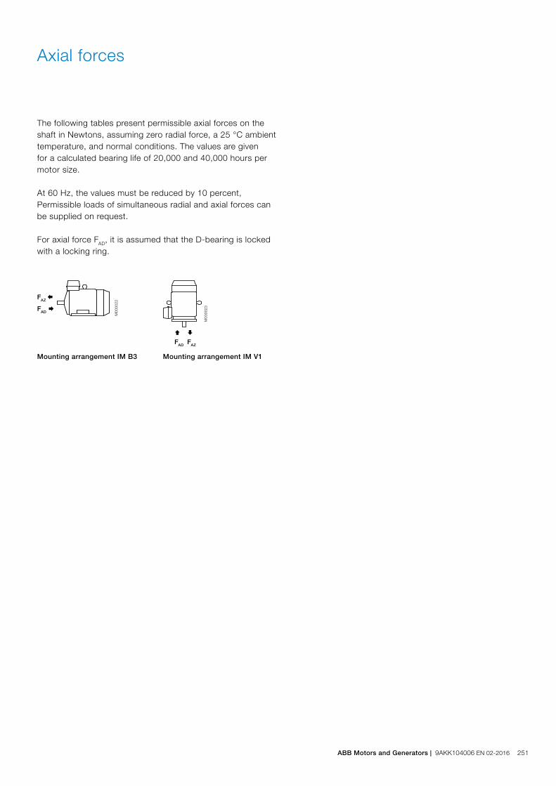
The following tables present permissible axial forces on the shaft in Newtons, assuming zero radial force, a 25 °C ambient temperature, and normal conditions. The values are given for a calculated bearing life of 20,000 and 40,000 hours per motor size.
At 60 Hz, the values must be reduced by 10 percent, Permissible loads of simultaneous radial and axial forces can be supplied on request.
For axial force FAD, it is assumed that the D-bearing is locked with a locking ring.
Axial forces
Ç
FAD
M00
0023
È
FAZ
FAD Æ
M00
0022
FAZ Å
Mounting arrangement IM B3 Mounting arrangement IM V1
ABB Motors and Generators | 9AKK104006 EN 02-2016 251

Permissible axial forces, motor sizes 90-280
Motor size Poles
Mounting arrangement IM B3, deep groove ball bearings Mounting arrangement IM V1, deep groove ball bearings
20 000 hours 40 000 hours 20 000 hours 40 000 hours
FAD (N) FAZ (N) FAD (N) FAZ (N) FAD (N) FAZ (N) FAD (N) FAZ (N)
90 2 885 485 720 320 945 450 775 280
4 1170 650 945 425 1245 600 1020 375
6 1270 870 1005 605 1360 815 1095 550
8 1410 1010 1110 710 1485 960 1185 660
100 2 1620 1120 1280 780 1710 1060 1370 715
4 2065 1565 1615 1115 2180 1485 1735 1035
6 2390 1890 1860 1360 2510 1815 1980 1285
8 2660 2160 2065 1565 2780 2080 2185 1485
112 M, MB 2 1615 1115 1275 775 1725 1040 1385 700
4 2060 1560 1610 1110 2210 1460 1110 1010
6 2385 1885 1860 1360 2540 1785 2010 1260
8 2655 2155 2060 1560 2790 2055 2195 1475
132 M, MA 4 2245 1645 1760 1160 2460 1505 1970 1015
6 2595 1980 2025 1425 2815 1850 2245 1280
8 2875 2270 2240 1640 3130 2115 2490 1470
132 MC 6 2580 1980 2010 1410 2885 1780 2315 1210
132 MBA 4 2235 1635 1750 1150 2495 1465 2010 980
132 S 6 2600 2000 2030 1435 2780 1885 2210 1315
8 2885 2285 2245 1645 3100 2145 2460 1505
132 SB 2 1760 1160 1400 800 1910 1075 1540 705
132 SBB, SC 2 1760 1160 1395 795 1945 1045 1575 670
132 SMB, SMC
2 2210 1610 1740 1140 2435 1470 1950 985
4 2840 2240 2205 1605 3150 2035 2515 1400
132 SMD 4 2830 2200 2230 1595 3195 1995 2560 1355
132 SME 2 2210 1610 1730 1130 2490 1425 2005 940
160 2 4160 4160 3425 3425 4560 3810 3860 3110
4 4740 4740 3920 3920 5260 4310 4440 3490
6 4840 4840 4000 4000 5400 4420 4540 3560
8 5980 5980 4920 4920 6560 5580 5460 4480
180 2 5480 5480 4600 1) 4600 1) 5920 5115 5060 1) 4255 1)
4 4360 4360 3540 3540 5080 3860 4240 3020
6 5980 5980 4940 4630 6000 5445 5600 4385
8 6000 6620 5460 5460 6000 6120 6000 4900
200 2 5000 6880 5000 2) 5700 2) 5000 6350 5000 2) 5230 2)
4 5000 7660 5000 6340 5000 6950 5000 5650
6 5000 8300 5000 6880 5000 7505 5000 6025
8 5000 9880 5000 8160 5000 9215 5000 7435
225 2 5000 7380 5000 3) 6120 3) 5000 6770 5000 3) 5490 3)
4 5000 7600 5000 6220 5000 6795 5000 5475
6 5000 10140 5000 8420 5000 9270 5000 7490
8 5000 11 420 5000 9460 5000 10 595 5000 8535
250 2 6000 4) 9020 4) 6000 4) 7500 4) 6000 4) 8335 4) 6000 4) 6755 4)
4 6000 9800 6000 8040 6000 8820 6000 7120
6 6000 11520 6000 9520 6000 10 275 6000 8235
8 6000 13 700 6000 11 380 6000 12 645 6000 10 205
280 2 5260 5260 4220 4220 6400 4400 5420 3420
4 6500 6500 5160 5160 7920 5400 6640 4120
6 7500 7500 6040 6040 8500 6180 7840 4640
8 7740 7740 6180 6180 8500 6435 7980 4775
1) The maximum lifetime of the grease is 38 000 h2) The maximum lifetime of the grease is 27 000 h3) The maximum lifetime of the grease is 23 000 h4) The maximum lifetime of the grease is 16 000 h
252 9AKK104006 EN 02-2016 | ABB Motors and Generators

Protection and mountingThe degree of protection for the standard terminal box is IP 55. It complies with the requirements of the protection method ‘t’ dust ignition protection and prevents all ignition sources such as sparks, excessive over heating etc. All terminal box seals are of uninterrupted type fulfilling the requirements for Ex t motors. By default, terminal boxes are mounted on top of the motor at D-end.
TurnabilityThe terminal box of motors in size 90-180 are integrated with the frame which means that the box itself cannot be rotated. There are however cable entries both on RHS and LHS to allow cabling from either side. Motors in size 200-280 have a terminal box made of deep drawn steel mounted on top of the stator, the box itself cannot be rotated but there are two openings with detachable gland plates, one on RHS and another on LHS of the box allowing cable entry from both sides.
Cable entriesTerminal box is provided as standard with plugged holes for cable glands, no cable glands are included as standard, the knockout entry holes and cable flange holes are closed with Ex t approved blanking plugs.
Terminal box
Cable type and terminationsTerminations are suitable for copper cables. Cables are connected to terminals by cable lugs, the lugs are not included in the delivery.
Earthing boltsThe motors are as standard provided with at least one earthing bolt inside the terminal box and another on the frame. The earthing bolt on the frame is located on top close to the terminal box.
ABB Motors and Generators | 9AKK104006 EN 02-2016 253
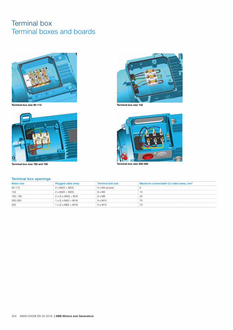
Terminal boxTerminal boxes and boards
Terminal box size 90-112 Terminal box size 132
Terminal box size 160 and 180 Terminal box size 200-280
Terminal box openingsMotor size Plugged cable entry Terminal bolt size Maximum connectable Cu-cable earea, mm2
90-112 2 x (M25 + M20) 6 x M4 (screw) 6
132 2 x (M25 + M20) 6 x M5 10
160, 180 2 x (2 x M40) + M16 6 x M6 35
200-250 1 x (2 x M40 + M16) 6 x M10 70
280 1 x (2 x M63 + M16) 6 x M10 70
254 9AKK104006 EN 02-2016 | ABB Motors and Generators
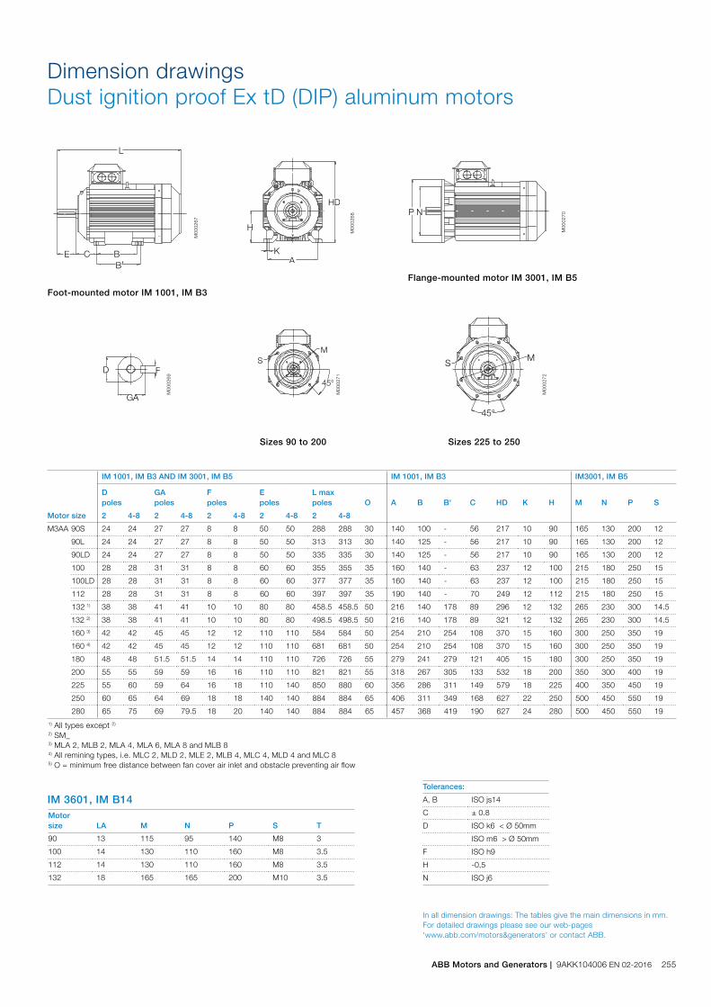
IM 3601, IM B14 Motor size LA M N P S T
90 13 115 95 140 M8 3
100 14 130 110 160 M8 3.5
112 14 130 110 160 M8 3.5
132 18 165 165 200 M10 3.5
In all dimension drawings: The tables give the main dimensions in mm. For detailed drawings please see our web-pages ‘www.abb.com/motors&generators’ or contact ABB.
Motor size
IM 1001, IM B3 AND IM 3001, IM B5 IM 1001, IM B3 IM3001, IM B5
Dpoles
GApoles
Fpoles
Epoles
L maxpoles O A B B' C HD K H M N P S
2 4-8 2 4-8 2 4-8 2 4-8 2 4-8
M3AA 90S 24 24 27 27 8 8 50 50 288 288 30 140 100 - 56 217 10 90 165 130 200 12
90L 24 24 27 27 8 8 50 50 313 313 30 140 125 - 56 217 10 90 165 130 200 12
90LD 24 24 27 27 8 8 50 50 335 335 30 140 125 - 56 217 10 90 165 130 200 12
100 28 28 31 31 8 8 60 60 355 355 35 160 140 - 63 237 12 100 215 180 250 15
100LD 28 28 31 31 8 8 60 60 377 377 35 160 140 - 63 237 12 100 215 180 250 15
112 28 28 31 31 8 8 60 60 397 397 35 190 140 - 70 249 12 112 215 180 250 15
132 1) 38 38 41 41 10 10 80 80 458.5 458.5 50 216 140 178 89 296 12 132 265 230 300 14.5
132 2) 38 38 41 41 10 10 80 80 498.5 498.5 50 216 140 178 89 321 12 132 265 230 300 14.5
160 3) 42 42 45 45 12 12 110 110 584 584 50 254 210 254 108 370 15 160 300 250 350 19
160 4) 42 42 45 45 12 12 110 110 681 681 50 254 210 254 108 370 15 160 300 250 350 19
180 48 48 51.5 51.5 14 14 110 110 726 726 55 279 241 279 121 405 15 180 300 250 350 19
200 55 55 59 59 16 16 110 110 821 821 55 318 267 305 133 532 18 200 350 300 400 19
225 55 60 59 64 16 18 110 140 850 880 60 356 286 311 149 579 18 225 400 350 450 19
250 60 65 64 69 18 18 140 140 884 884 65 406 311 349 168 627 22 250 500 450 550 19
280 65 75 69 79.5 18 20 140 140 884 884 65 457 368 419 190 627 24 280 500 450 550 19
1) All types except 2) 2) SM_3) MLA 2, MLB 2, MLA 4, MLA 6, MLA 8 and MLB 84) All remining types, i.e. MLC 2, MLD 2, MLE 2, MLB 4, MLC 4, MLD 4 and MLC 85) O = minimum free distance between fan cover air inlet and obstacle preventing air flow
Tolerances:
A, B ISO js14
C ± 0.8
D ISO k6 < Ø 50mm
ISO m6 > Ø 50mm
F ISO h9
H -0,5
N ISO j6
L
C BB’
E
H
KA
HD
GA
FD
P N
45°
SM
MS
45°
Foot-mounted motor IM 1001, IM B3
Sizes 90 to 200
M00
0267
M00
0268
M00
0270
M00
0269
M00
0271
M00
0272
Flange-mounted motor IM 3001, IM B5
Sizes 225 to 250
Dimension drawingsDust ignition proof Ex tD (DIP) aluminum motors
ABB Motors and Generators | 9AKK104006 EN 02-2016 255
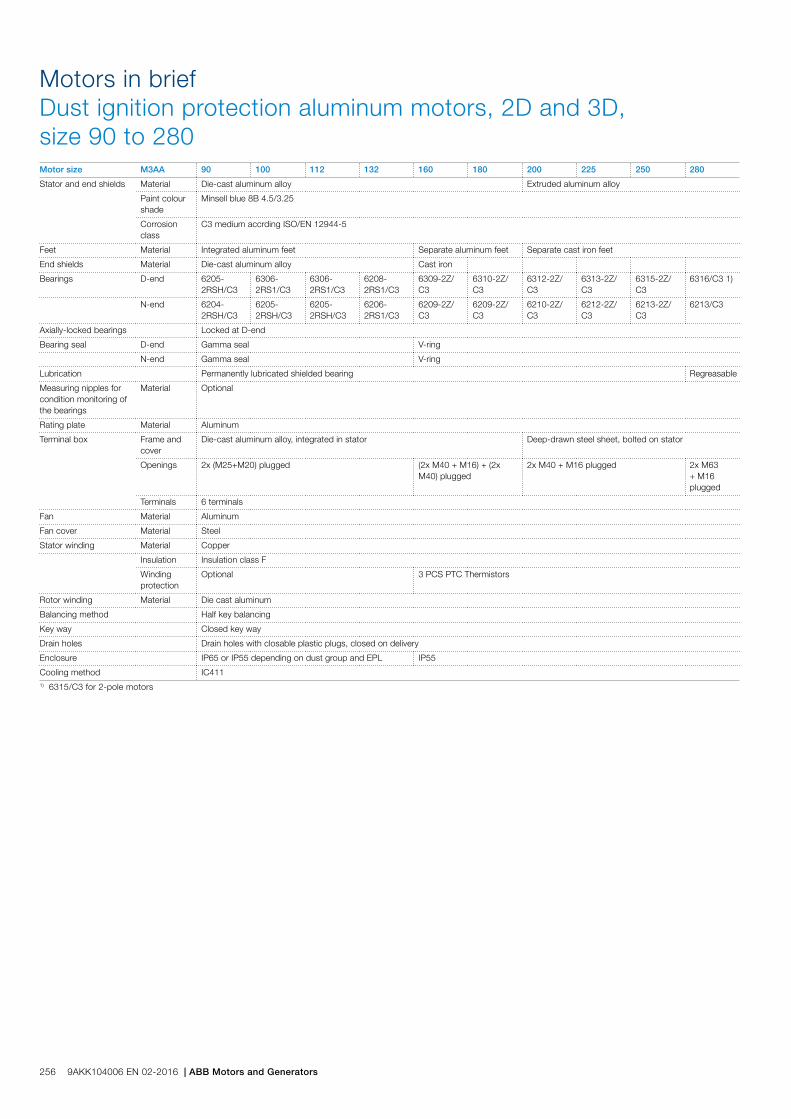
Motors in briefDust ignition protection aluminum motors, 2D and 3D, size 90 to 280Motor size M3AA 90 100 112 132 160 180 200 225 250 280
Stator and end shields Material Die-cast aluminum alloy Extruded aluminum alloy
Paint colour shade
Minsell blue 8B 4.5/3.25
Corrosion class
C3 medium accrding ISO/EN 12944-5
Feet Material Integrated aluminum feet Separate aluminum feet Separate cast iron feet
End shields Material Die-cast aluminum alloy Cast iron
Bearings D-end 6205-2RSH/C3
6306-2RS1/C3
6306-2RS1/C3
6208-2RS1/C3
6309-2Z/C3
6310-2Z/C3
6312-2Z/C3
6313-2Z/C3
6315-2Z/C3
6316/C3 1)
N-end 6204-2RSH/C3
6205-2RSH/C3
6205-2RSH/C3
6206-2RS1/C3
6209-2Z/C3
6209-2Z/C3
6210-2Z/C3
6212-2Z/C3
6213-2Z/C3
6213/C3
Axially-locked bearings Locked at D-end
Bearing seal D-end Gamma seal V-ring
N-end Gamma seal V-ring
Lubrication Permanently lubricated shielded bearing Regreasable
Measuring nipples for condition monitoring of the bearings
Material Optional
Rating plate Material Aluminum
Terminal box Frame and cover
Die-cast aluminum alloy, integrated in stator Deep-drawn steel sheet, bolted on stator
Openings 2x (M25+M20) plugged (2x M40 + M16) + (2x M40) plugged
2x M40 + M16 plugged 2x M63 + M16 plugged
Terminals 6 terminals
Fan Material Aluminum
Fan cover Material Steel
Stator winding Material Copper
Insulation Insulation class F
Winding protection
Optional 3 PCS PTC Thermistors
Rotor winding Material Die cast aluminum
Balancing method Half key balancing
Key way Closed key way
Drain holes Drain holes with closable plastic plugs, closed on delivery
Enclosure IP65 or IP55 depending on dust group and EPL IP55
Cooling method IC4111) 6315/C3 for 2-pole motors
256 9AKK104006 EN 02-2016 | ABB Motors and Generators
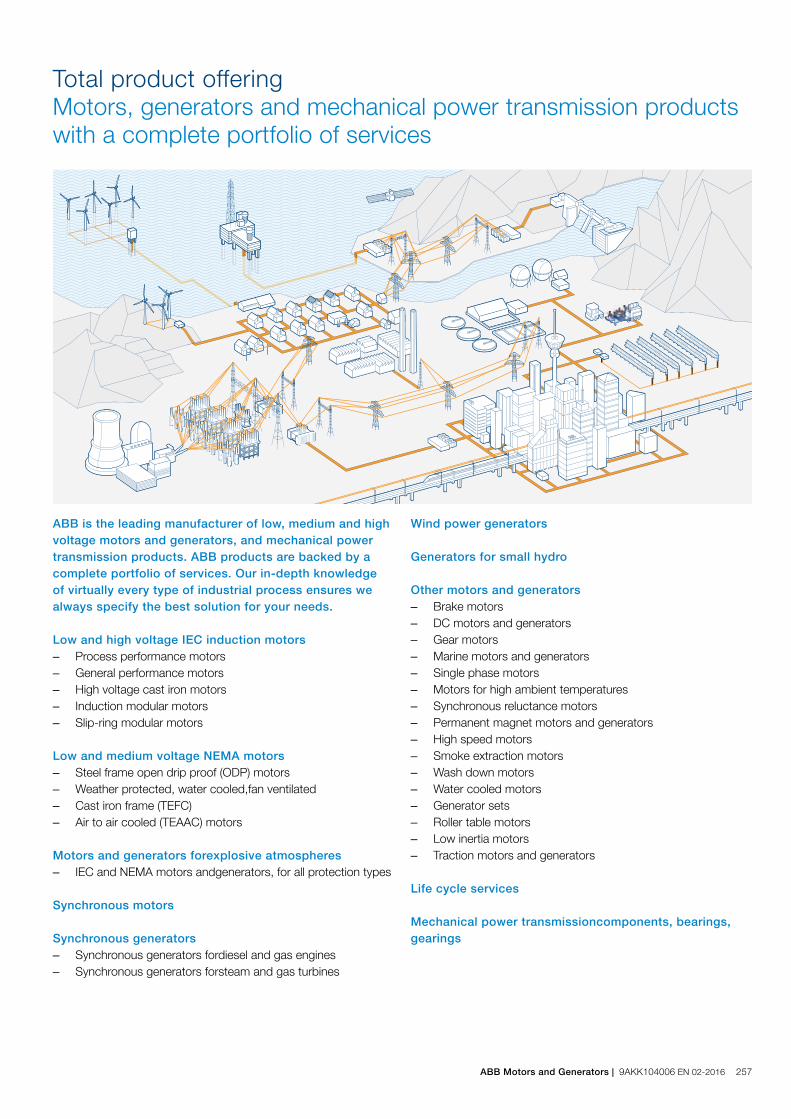
Total product offeringMotors, generators and mechanical power transmission products with a complete portfolio of services
Wind power generators Generators for small hydro Other motors and generators – Brake motors – DC motors and generators – Gear motors – Marine motors and generators – Single phase motors – Motors for high ambient temperatures – Synchronous reluctance motors – Permanent magnet motors and generators – High speed motors – Smoke extraction motors – Wash down motors – Water cooled motors – Generator sets – Roller table motors – Low inertia motors – Traction motors and generators
Life cycle services Mechanical power transmissioncomponents, bearings, gearings
ABB is the leading manufacturer of low, medium and high voltage motors and generators, and mechanical power transmission products. ABB products are backed by a complete portfolio of services. Our in-depth knowledge of virtually every type of industrial process ensures we always specify the best solution for your needs. Low and high voltage IEC induction motors – Process performance motors – General performance motors – High voltage cast iron motors – Induction modular motors – Slip-ring modular motors
Low and medium voltage NEMA motors – Steel frame open drip proof (ODP) motors – Weather protected, water cooled,fan ventilated – Cast iron frame (TEFC) – Air to air cooled (TEAAC) motors
Motors and generators forexplosive atmospheres – IEC and NEMA motors andgenerators, for all protection types
Synchronous motors Synchronous generators – Synchronous generators fordiesel and gas engines – Synchronous generators forsteam and gas turbines
ABB Motors and Generators | 9AKK104006 EN 02-2016 257
Spare partsSpare parts and support are offered throughout the life cycle of ABB products. In addition to individual spares, tailored spare part packages are also available. Repair and refurbishmentSupport for all ABB motors and generators and other brands is provided by ABB’s global service organization. Specialist teams can also deliver emergency support. Migration and upgradesLife cycle audits determine the optimum upgrades and migra-tion paths. Upgrades range from individual components to direct replacement motors and generators. TrainingProduct and service training courses take a practical approach. The training ranges from standard courses to specially tailored programs to suit customer requirements. Specialized supportSpecialized support is offered through ABB’s global service orga-nization. Local units provide major and minor repairs as well as overhauls and reconditioning. Service contractsService contracts are tailored to the customer’s needs. The contracts combine ABB’s entire service portfolio and 120 years of experience to deploy the optimal service practices.
ABB offers a complete portfolio of services to ensure trouble-free operation and long product lifetimes. These services cover the entire life cycle. Local support is pro-vided through a global network of ABB service centers and certified partners. Pre-purchaseABB’s front-end sales organization can help customers to quickly and efficiently select, configure and optimize the right motor or generator for their application. Installation and commissioningProfessional installation and commissioning by ABB’s certified engineers represent an investment in availability and reliability over the entire life cycle. Engineering and consultingABB’s experts provide energy efficiency and reliability appraisals, advanced condition and performance assessments and technical studies. Condition monitoring and diagnosisUnique services collect and analyze data to provide early warn-ings of problems before failures can occur. All critical areas of the equipment are covered. Maintenance and field servicesABB offers life cycle management plans and preventive main-tenance products. The recommended four-level maintenance program covers the entire product lifetime.
Life cycle services and supportFrom pre-purchase to migration and upgrades
258 9AKK104006 EN 02-2016 | ABB Motors and Generators

ABB Motors and Generators | 9AKK104006 EN 02-2016 259
Contact us
www.abb.com/motors&generators We reserve the right to make technical changes or modify
the contents of this document without prior notice. With
regard to purchase orders, the agreed particulars shall
prevail. ABB does not accept any responsibil ity what so
ever for potential errors or possible lack of information in
this document.
We reserve all rights in this document and in the subject
matter and il lustrations contained herein. Any reproduc-
tion, disclosure to third parties or uti l ization of its contents
– in whole or in parts – is forbidden without prior written
consent of ABB.
© Copyright 2016 ABB.
All rights reserved.
9AK
K10
4006
EN
02-
2016
Related Documents